US8941423B2 - Method for operating a circuit including a timing calibration function - Google Patents
Method for operating a circuit including a timing calibration functionDownload PDFInfo
- Publication number
- US8941423B2 US8941423B2US14/205,254US201414205254AUS8941423B2US 8941423 B2US8941423 B2US 8941423B2US 201414205254 AUS201414205254 AUS 201414205254AUS 8941423 B2US8941423 B2US 8941423B2
- Authority
- US
- United States
- Prior art keywords
- path
- delay
- calibration
- mission
- paths
- Prior art date
- Legal status (The legal status is an assumption and is not a legal conclusion. Google has not performed a legal analysis and makes no representation as to the accuracy of the status listed.)
- Active
Links
Images


Classifications
- G—PHYSICS
- G06—COMPUTING OR CALCULATING; COUNTING
- G06F—ELECTRIC DIGITAL DATA PROCESSING
- G06F13/00—Interconnection of, or transfer of information or other signals between, memories, input/output devices or central processing units
- G06F13/14—Handling requests for interconnection or transfer
- G06F13/36—Handling requests for interconnection or transfer for access to common bus or bus system
- G06F13/362—Handling requests for interconnection or transfer for access to common bus or bus system with centralised access control
- G06F13/3625—Handling requests for interconnection or transfer for access to common bus or bus system with centralised access control using a time dependent access
- G—PHYSICS
- G06—COMPUTING OR CALCULATING; COUNTING
- G06F—ELECTRIC DIGITAL DATA PROCESSING
- G06F13/00—Interconnection of, or transfer of information or other signals between, memories, input/output devices or central processing units
- G06F13/14—Handling requests for interconnection or transfer
- G06F13/16—Handling requests for interconnection or transfer for access to memory bus
- G06F13/1668—Details of memory controller
- G06F13/1689—Synchronisation and timing concerns
- G—PHYSICS
- G06—COMPUTING OR CALCULATING; COUNTING
- G06F—ELECTRIC DIGITAL DATA PROCESSING
- G06F13/00—Interconnection of, or transfer of information or other signals between, memories, input/output devices or central processing units
- G06F13/38—Information transfer, e.g. on bus
- G06F13/42—Bus transfer protocol, e.g. handshake; Synchronisation
- G06F13/4247—Bus transfer protocol, e.g. handshake; Synchronisation on a daisy chain bus
- G06F13/4256—Bus transfer protocol, e.g. handshake; Synchronisation on a daisy chain bus using a clocked protocol
- G—PHYSICS
- G11—INFORMATION STORAGE
- G11C—STATIC STORES
- G11C29/00—Checking stores for correct operation ; Subsequent repair; Testing stores during standby or offline operation
- G11C29/02—Detection or location of defective auxiliary circuits, e.g. defective refresh counters
- G11C29/022—Detection or location of defective auxiliary circuits, e.g. defective refresh counters in I/O circuitry
- G—PHYSICS
- G11—INFORMATION STORAGE
- G11C—STATIC STORES
- G11C29/00—Checking stores for correct operation ; Subsequent repair; Testing stores during standby or offline operation
- G11C29/02—Detection or location of defective auxiliary circuits, e.g. defective refresh counters
- G11C29/023—Detection or location of defective auxiliary circuits, e.g. defective refresh counters in clock generator or timing circuitry
- G—PHYSICS
- G11—INFORMATION STORAGE
- G11C—STATIC STORES
- G11C29/00—Checking stores for correct operation ; Subsequent repair; Testing stores during standby or offline operation
- G11C29/02—Detection or location of defective auxiliary circuits, e.g. defective refresh counters
- G11C29/028—Detection or location of defective auxiliary circuits, e.g. defective refresh counters with adaption or trimming of parameters
- H—ELECTRICITY
- H03—ELECTRONIC CIRCUITRY
- H03K—PULSE TECHNIQUE
- H03K5/00—Manipulating of pulses not covered by one of the other main groups of this subclass
- H03K5/13—Arrangements having a single output and transforming input signals into pulses delivered at desired time intervals
- H03K5/133—Arrangements having a single output and transforming input signals into pulses delivered at desired time intervals using a chain of active delay devices
- H—ELECTRICITY
- H03—ELECTRONIC CIRCUITRY
- H03K—PULSE TECHNIQUE
- H03K5/00—Manipulating of pulses not covered by one of the other main groups of this subclass
- H03K5/13—Arrangements having a single output and transforming input signals into pulses delivered at desired time intervals
- H03K5/14—Arrangements having a single output and transforming input signals into pulses delivered at desired time intervals by the use of delay lines
- H—ELECTRICITY
- H03—ELECTRONIC CIRCUITRY
- H03L—AUTOMATIC CONTROL, STARTING, SYNCHRONISATION OR STABILISATION OF GENERATORS OF ELECTRONIC OSCILLATIONS OR PULSES
- H03L7/00—Automatic control of frequency or phase; Synchronisation
- H03L7/06—Automatic control of frequency or phase; Synchronisation using a reference signal applied to a frequency- or phase-locked loop
- H03L7/08—Details of the phase-locked loop
- H03L7/081—Details of the phase-locked loop provided with an additional controlled phase shifter
- H03L7/0812—Details of the phase-locked loop provided with an additional controlled phase shifter and where no voltage or current controlled oscillator is used
- H—ELECTRICITY
- H03—ELECTRONIC CIRCUITRY
- H03L—AUTOMATIC CONTROL, STARTING, SYNCHRONISATION OR STABILISATION OF GENERATORS OF ELECTRONIC OSCILLATIONS OR PULSES
- H03L7/00—Automatic control of frequency or phase; Synchronisation
- H03L7/06—Automatic control of frequency or phase; Synchronisation using a reference signal applied to a frequency- or phase-locked loop
- H03L7/08—Details of the phase-locked loop
- H03L7/10—Details of the phase-locked loop for assuring initial synchronisation or for broadening the capture range
- G—PHYSICS
- G11—INFORMATION STORAGE
- G11C—STATIC STORES
- G11C8/00—Arrangements for selecting an address in a digital store
- G11C8/18—Address timing or clocking circuits; Address control signal generation or management, e.g. for row address strobe [RAS] or column address strobe [CAS] signals
- H—ELECTRICITY
- H03—ELECTRONIC CIRCUITRY
- H03K—PULSE TECHNIQUE
- H03K5/00—Manipulating of pulses not covered by one of the other main groups of this subclass
- H03K2005/00013—Delay, i.e. output pulse is delayed after input pulse and pulse length of output pulse is dependent on pulse length of input pulse
- H03K2005/00019—Variable delay
Definitions
- the present inventionrelates generally to interface circuits, typically implemented on integrated circuits such as Processor chips, memory controller chips, and SOC (System On Chip) integrated circuits where such interfaces are required.
- integrated circuitssuch as Processor chips, memory controller chips, and SOC (System On Chip) integrated circuits where such interfaces are required.
- SOCSystem On Chip
- One common example of such an interfacewould receive data read from dynamic memory chips that are located externally to a device containing the receiving interface.
- One application where such a continuously adaptive calibration or training mechanism for data interface timing calibration is especially usefulis to compensate for variable system-level delays in dynamic memory interfaces where DQ data bits can develop a skew problem with respect to the DQS strobe used to sample them, or where the optimal DQS strobe timing over all data bits varies during the functional operation of the system.
- the timing interface between the Phy and internal core clock domains in a dynamic memory based controller systemthe timing relationship between an internal capture clock and data coming from the Phy can also drift due to system-level delays.
- jittercan develop between data bits and strobes, or between signals in different clock domains, and it would also be useful to resolve jitter issues while performing a continuous timing calibration function.
- a mission data pathis established where a data bit is sampled by a strobe.
- a similar reference data pathis established for calibration purposes only. At an initialization time both paths are calibrated and a delta value between them is established.
- the calibration pathcontinuously performs calibration operations to determine if its optimal delay has changed by more than a threshold value. If so, the new delay setting for the reference path is used to change the delay setting for the mission path after adjustment by the delta value. Since the determination of calibration is performed solely on the reference path, and the transfer of delay parameters to the mission path is almost instantaneous, signal traffic on the mission path is not interrupted in order for even frequent re-calibrations to be performed.
- Circuits and methodsare also disclosed for performing multiple parallel calibrations for the reference path to speed up the training process. Where multiple parallel calibrations are implemented, the continuous adaptive training function according to the invention enables a mission data path to be recalibrated more frequently in applications where delays may change rapidly during system operation.
- the principles described hereincan be utilized to adjust any timing relationship where one signal is used to sample another signal.
- the signal being sampledmay be programmably delayed according to the invention, or a strobe signal used for sampling may instead be programmably delayed.
- jittermay be evident on either a strobe signal or a signal being sampled by the strobe signal, and circuits and methods are included for providing minimum numbers of delay increments for delay measurements such that false measurements due to jitter are avoided during a calibration process.
- effortsare made to equalize the timing relationship between mission and reference data paths such that any timing delta between them is minimized.
- FIG. 1shows exemplary and non-limiting embodiments for generalized circuit descriptions describing different aspects of the invention.
- FIG. 2shows an exemplary overall flowchart for continuous adaptive training according to the invention.
- FIG. 3shows an exemplary flowchart for calibration sweeps during continuous adaptive training calibration according to the invention.
- FIG. 4shows an exemplary timing diagram in accordance with the flowchart of FIG. 3 including provision for jitter detection and avoidance.
- FIG. 5shows a circuit diagram for a system implementation that incorporates an SCL (Self-Configuring Logic) circuit implementation as described in U.S. Pat. No. 7,975,164, and indicating timing areas where a continuous adaptive training functionality according to the invention may be applied.
- SCLSelf-Configuring Logic
- FIG. 6shows an exemplary flowchart for an embodiment of the invention when applied to the SCL application of FIG. 5 .
- FIG. 7shows an exemplary and non-limiting embodiment for an implementation of the invention where a plurality of DLLs are utilized in parallel to reduce the time required for reference path re-calibration during operation of the invention.
- FIG. 8shows an exemplary timing diagram for the embodiment of FIG. 7 including provision for jitter detection and avoidance.
- Circuits and methods for implementing a continuously adaptive timing calibration training function in an integrated circuit interfaceare disclosed.
- a mission data pathis established where a data bit is sampled by a strobe.
- a similar reference data pathis established for calibration purposes only. At an initialization time both paths are calibrated and a delta value between them is established.
- the calibration pathcontinuously performs calibration operations to determine if its optimal delay has changed by more than a threshold value. If so, the new delay setting for the reference path is used to change the delay setting for the mission path after adjustment by the delta value.
- Circuits and methodsare also disclosed for performing multiple parallel calibrations for the reference path to speed up the training process.
- Timing calibration according to the inventionis able to be run dynamically and continuously
- Re-calibrationis performed in nanoseconds and for most system configurations—especially those including memory system interfaces—there are always opportunities to perform an instantaneous transfer of delay line (DLL) settings without affecting proper operation. For example, it is usually acceptable to transfer delay parameters during a memory write cycle to a timing circuit supporting memory read operations. A full re-initializing of both reference and mission paths takes longer but is still fast enough to run during longer periods such as during memory refresh operations.
- DLLdelay line
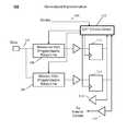
- FIG. 1shows a generalized implementation for one exemplary and non-limiting embodiment of the invention.
- a data signal 102is sampled by a strobe signal 104 .
- data signal 102feeds two delay line (DLL) paths—a mission path 106 and a reference path 108 .
- DLLdelay line
- the outputs of these delay linesare sampled in flip-flops 112 and 114 respectively, and the outputs of these flip-flops are available to CAT (Continuous Adaptive Training) control circuit 110 as well as other internal circuits by way of buffer 116 .
- CATContinuous Adaptive Training
- buffer 118has been added as a load on the output of flip-flop 112 even though it is not necessary since the output of flip-flop 112 only drives CAT control circuit 110 .
- FIG. 1shows data bit 102 being delayed through the reference and mission paths, and alternate implementation of a similar function can be constructed according to the invention by delaying strobe signal 104 through separate reference and mission data path DLLs, and utilizing the resultant delayed strobes to sample data bit 102 .
- FIG. 2shows a flowchart 200 describing the function of a circuit constructed according to an exemplary embodiment of the invention.
- initial calibrationsare performed for both the mission DLL in the mission data path and the reference DLL in the reference data path. Since the initial calibration requires a calibration operation on the mission data path, this is one operation where traffic on the mission data path is interrupted, and is therefore best performed during an initial power-on calibration of a system containing the invention, or alternately performed during time periods such as memory refresh operations where the mission data path is not utilized for a duration wherein such an initial calibration can be performed.
- a sweepis performed on each data path whereby data is captured at each increment of delay line delay from a starting point until an endpoint is reached.
- a detection conditionis reached during the sweep that indicates the sweep process should terminate.
- a conditionis detecting a transition on the data bit value being sampled.
- Such transitioncould be a 0-to-1 transition or alternatively a 1-to-0 transition depending upon the application.
- Initial calibration of the reference data pathis shown as delay setting R 0 . Specific details of performing such a calibration sweep are shown in FIG. 3 .
- a DLL Delta ( ⁇ ) valuehas been established that is equal to the value (M 0 ⁇ R 0 ).
- step 204function of the mission path is initiated according to normal system operation utilizing delay setting M 0 .
- the reference data pathis again calibrated and a new delay setting for the reference DLL is determined to be R 1 . Note that subsequent recalibration of the reference path has no effect on normal system operation utilizing the mission data path.
- step 208the absolute value of (R 1 ⁇ R 0 ) is computed and compared with a change threshold value (T C ). If the absolute value of (R 1 ⁇ R 0 ) is less than T C , then it is determined that any drift in system timing since the previous calibration is small enough that no adjustment to the calibration of the mission path is necessary.
- a new DLL delay setting value M 1is computed, and then per step 212 is applied to the mission path.
- FIG. 3shows a flowchart 300 describing a calibration sweep for either the reference DLL or the mission DLL.
- the DLL being calibratedis set for example to a minimum delay as the starting point for the sweep.
- the DLL delayis incremented and then the sampled data bit is captured 306 by a delayed sample strobe (for an exemplary implementation where the sample strobe is delayed by the reference and mission DLLs). Note that in an alternate embodiment the captured data bit may be delayed instead of delaying the sample strobe.
- a transition on the captured data bitis detected which may be either a 0-to-1 transition or alternately a 1-to-0 transition. If per step 308 no transition is detected the flow returns to step 304 where the DLL is incremented again. When a transition is detected, the flow proceeds to step 310 where the DLL value is recorded and the sweep ends.
- a timing diagram 400 for the process of FIG. 3is shown in FIG. 4 .
- data bit 402is sampled by a strobe 404 which is swept 410 from starting delay 406 until end delay 408 is reached upon detection of falling edge 414 of data bit 402 .
- the transition causing the end of the sweepmay instead be rising edge 412 .
- any jitter 416 occurring on either the strobe or the data bitmay cause an incorrect determination of the condition for ending the sweep. For instance in the diagram of FIG.
- the inventionincludes the requirement for any detected transitions to be separated from other detected transitions by at least a jitter threshold margin of delay.
- a jitter threshold marginmay be set to any number of DLL delay increments according to the requirements of a specific application.
- One application for the inventionincludes timing calibration for a DRAM controller circuit as described in U.S. Pat. No. 7,975,164. As described in circuit diagram 500 of FIG. 5 , that patent describes a controller circuit that includes a function 502 entitled Self-configuring Logic which enables signals to be transferred from the Phy to the core clock domain of a circuit receiving data from a DDRAM.
- One application for a CAT function according to the inventionis calibration of the delay for DLL 504 controlling the Capture_Clk signal.
- Another application for a CAT function according to the inventionis calibration of the delay for DLL 506 which delays the DQS strobe in the Phy.
- Flowchart 600 of FIG. 6describes the process for calibration of the delay for DLL 504 controlling the Capture_Clk signal in the circuit of FIG. 5 .
- initial sweep calibrationsare performed for a mission DLL and a reference DLL where start and end points are determined.
- a midpoint of each calibration sweepis utilized as a timing calibration delay value as opposed to the endpoint of a sweep.
- midpointsare established for calibration sweeps of both reference and mission paths.
- a Delta ( ⁇ ) valueis established between the midpoint delay of the reference data path and the midpoint delay of the mission data path.
- a new midpoint delay valueis established for the reference data path without disturbing operation of the mission data path.
- the new midpoint delay value MidiRefis compared 610 with the previous midpoint delay value (Mid 0 Ref) for the reference path, and if the absolute value of the difference between them is greater than a change threshold value (Tc), then the mission DLL is updated with new value MidiMis at the next opportunity, and again without disturbing functional operation of the mission data path.
- Tcchange threshold value
- any new value for the mission DLL data pathis adjusted with respect to a revised reference DLL value by the Delta ( ⁇ ) value between them established during the initial calibration of step 602 . Note that the application described with respect to FIGS.
- the delay value corresponding to the end point of a calibration sweepis not chosen as the delay timing value for the mission path.
- Any timing valuemay be determined for implementation in the mission path based on transitions detected during a delay calibration sweep, and based on delays corresponding to those transitions an optimal timing delay can be determined for a specific application.
- a falling edge transitionmay be detected followed by the detection of a rising edge, and then an optimal timing calibration point is calculated to be half-way between the two detected transitions.
- circuit diagram 700 of FIG. 7where a plurality of delay lines are utilized in parallel to speed up calibration of the reference path of a CAT function according to the invention.
- data bit 702is shown driving a plurality of delay lines 708 - 714 with the results being captured in flip-flop's according to a strobe signal 704 and controlled by CAT control circuit 706 .
- the strobe signal 704could be delayed in a plurality of delay lines instead of delaying data bit 702 .
- Each of delay lines 708 - 714is responsible for analyzing only a portion of a calibration sweep with delay line 708 handling a first portion and delay line 714 handling the last portion.
- Delay lines 710 and 712handle intermediate portions of the sweep. Note that physical portions of delay lines 708 , 710 , and 712 have been grayed-out, and marked as 716 , 718 and 720 respectively. The grayed-out areas indicate physical portions of a delay line which need not be implemented since those delay increments are not required during operation and can therefore be depopulated. Only the portions of a delay line shown as not grayed out are utilized due to the fact that each delay line is only responsible for a portion of a calibration sweep.
- FIG. 7specifically shows four DLLs operating in parallel and as a result the calibration time for the reference path is reduced by a factor of four.
- different numbers of multiple DLLsmay be included within the spirit of the embodiment of FIG. 7 .
- eight DLLsmay be used in parallel to reduce the calibration time for the reference path by a factor of eight.
- any number of DLLsmay be chosen for this implementation according to the needs of the system.
- a delay sweep of 256 delay incrementsone could implement a circuit with 256 DLLs in parallel.
- additional DLLsdiminishes accordingly, however additional circuitry is included using more silicon real estate. As such, a designer may make an appropriate trade-off between calibration time and silicon consumption for any given system implementation.
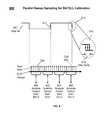
- FIG. 8A calibration sweep for the multiple DLL implementation of FIG. 7 is shown in FIG. 8 .
- data bit 802is being sampled by strobe 804 which is delayed and swept 810 from start delay increment 806 through an end delay at increment 808 .
- Transitions 812 and 814 of data bit 802are possible determination points for ending a sweep. In this example falling edge 814 has been chosen as the determination condition for ending the sweep.
- sweep 810is divided into sections 820 - 826 . Delay increments encompassed by section 820 of sweep 810 correspond to DLL 0 708 of FIG. 7 .
- Delay increments encompassed by section 822 of sweep 810correspond to DLL 1 710 of FIG. 7 .
- Delay increments encompassed by section 824 of sweep 810correspond to DLL 2 712 of FIG. 7 .
- Delay increments encompassed by section 826 of sweep 810correspond to DLL 3 714 of FIG. 7 .
- DLL 0is only responsible for analyzing the first 25% of a delay sweep, it is not necessary to include the circuitry for the other 75% 716 of that delay line, which can then be depopulated to save silicon real estate.
- DLL 3is responsible for the last 25% of the delay line, and thus requires all of the preceding 75%. DLL 3 is therefore not depopulated.
- any jitter 816 occurring on either the strobe or the data bitmay cause an incorrect determination of the condition for ending the sweep.
- the inventionincludes the requirement for any detected transitions to be separated from other detected transitions by at least a jitter threshold margin of delay.
- a jitter threshold marginmay be set to any number of DLL delay increments according to the requirements of a specific application.
- the implementationmay include the use of a computer system having a processor and a memory under the control of the processor, the memory storing instructions adapted to enable the processor to carry out operations as described hereinabove.
- the implementationmay be realized, in a concrete manner, as a computer program product that includes a non-transient and tangible computer readable medium holding instructions adapted to enable a computer system to perform the operations as described above.
Landscapes
- Engineering & Computer Science (AREA)
- Theoretical Computer Science (AREA)
- Physics & Mathematics (AREA)
- General Engineering & Computer Science (AREA)
- General Physics & Mathematics (AREA)
- Nonlinear Science (AREA)
- Microelectronics & Electronic Packaging (AREA)
- Synchronisation In Digital Transmission Systems (AREA)
- Dram (AREA)
- Pulse Circuits (AREA)
- Information Transfer Systems (AREA)
Abstract
Description
Claims (23)
Priority Applications (10)
| Application Number | Priority Date | Filing Date | Title |
|---|---|---|---|
| US14/205,254US8941423B2 (en) | 2013-03-12 | 2014-03-11 | Method for operating a circuit including a timing calibration function |
| PCT/US2014/024818WO2014165214A2 (en) | 2013-03-12 | 2014-03-12 | Continuous adaptive training for data interface timing calibration |
| US14/850,792US9425778B2 (en) | 2013-03-12 | 2015-09-10 | Continuous adaptive data capture optimization for interface circuits |
| US15/237,473US9898433B2 (en) | 2013-03-12 | 2016-08-15 | Continuous adaptive data capture optimization for interface circuits |
| US15/853,568US20180121382A1 (en) | 2013-03-12 | 2017-12-22 | Continuous adaptive data capture optimization for interface circuits |
| US16/254,436US20190286591A1 (en) | 2013-03-12 | 2019-01-22 | Continuous adaptive data capture optimization for interface circuits |
| US17/074,403US11334509B2 (en) | 2013-03-12 | 2020-10-19 | Continuous adaptive data capture optimization for interface circuits |
| US17/724,221US11714769B2 (en) | 2013-03-12 | 2022-04-19 | Continuous adaptive data capture optimization for interface circuits |
| US18/209,083US12019573B2 (en) | 2013-03-12 | 2023-06-13 | Continuous adaptive data capture optimization for interface circuits |
| US18/665,365US20240303209A1 (en) | 2013-03-12 | 2024-05-15 | Continuous adaptive data capture optimization for interface circuits |
Applications Claiming Priority (2)
| Application Number | Priority Date | Filing Date | Title |
|---|---|---|---|
| US201361777648P | 2013-03-12 | 2013-03-12 | |
| US14/205,254US8941423B2 (en) | 2013-03-12 | 2014-03-11 | Method for operating a circuit including a timing calibration function |
Related Parent Applications (3)
| Application Number | Title | Priority Date | Filing Date |
|---|---|---|---|
| US14/205,208ContinuationUS8947140B2 (en) | 2013-03-12 | 2014-03-11 | Continuous adaptive training for data interface timing calibration |
| US14/205,225ContinuationUS8941422B2 (en) | 2013-03-12 | 2014-03-11 | Method for operating a data interface circuit where a calibration controller controls both a mission path and a reference path |
| US14/850,792ContinuationUS9425778B2 (en) | 2013-03-12 | 2015-09-10 | Continuous adaptive data capture optimization for interface circuits |
Related Child Applications (3)
| Application Number | Title | Priority Date | Filing Date |
|---|---|---|---|
| US14/205,225ContinuationUS8941422B2 (en) | 2013-03-12 | 2014-03-11 | Method for operating a data interface circuit where a calibration controller controls both a mission path and a reference path |
| US14/205,239ContinuationUS9100027B2 (en) | 2013-03-12 | 2014-03-11 | Data interface circuit for capturing received data bits including continuous calibration |
| US14/273,416ContinuationUS9300443B2 (en) | 2013-03-12 | 2014-05-08 | Methods for dynamically adaptive bit-leveling by incremental sampling, jitter detection, and exception handling |
Publications (2)
| Publication Number | Publication Date |
|---|---|
| US20140266349A1 US20140266349A1 (en) | 2014-09-18 |
| US8941423B2true US8941423B2 (en) | 2015-01-27 |
Family
ID=51524852
Family Applications (8)
| Application Number | Title | Priority Date | Filing Date |
|---|---|---|---|
| US14/205,254ActiveUS8941423B2 (en) | 2013-03-12 | 2014-03-11 | Method for operating a circuit including a timing calibration function |
| US14/205,208ActiveUS8947140B2 (en) | 2013-03-12 | 2014-03-11 | Continuous adaptive training for data interface timing calibration |
| US14/205,239Active2034-04-19US9100027B2 (en) | 2013-03-12 | 2014-03-11 | Data interface circuit for capturing received data bits including continuous calibration |
| US14/205,225ActiveUS8941422B2 (en) | 2013-03-12 | 2014-03-11 | Method for operating a data interface circuit where a calibration controller controls both a mission path and a reference path |
| US14/850,792ActiveUS9425778B2 (en) | 2013-03-12 | 2015-09-10 | Continuous adaptive data capture optimization for interface circuits |
| US15/237,473ActiveUS9898433B2 (en) | 2013-03-12 | 2016-08-15 | Continuous adaptive data capture optimization for interface circuits |
| US15/853,568AbandonedUS20180121382A1 (en) | 2013-03-12 | 2017-12-22 | Continuous adaptive data capture optimization for interface circuits |
| US16/254,436AbandonedUS20190286591A1 (en) | 2013-03-12 | 2019-01-22 | Continuous adaptive data capture optimization for interface circuits |
Family Applications After (7)
| Application Number | Title | Priority Date | Filing Date |
|---|---|---|---|
| US14/205,208ActiveUS8947140B2 (en) | 2013-03-12 | 2014-03-11 | Continuous adaptive training for data interface timing calibration |
| US14/205,239Active2034-04-19US9100027B2 (en) | 2013-03-12 | 2014-03-11 | Data interface circuit for capturing received data bits including continuous calibration |
| US14/205,225ActiveUS8941422B2 (en) | 2013-03-12 | 2014-03-11 | Method for operating a data interface circuit where a calibration controller controls both a mission path and a reference path |
| US14/850,792ActiveUS9425778B2 (en) | 2013-03-12 | 2015-09-10 | Continuous adaptive data capture optimization for interface circuits |
| US15/237,473ActiveUS9898433B2 (en) | 2013-03-12 | 2016-08-15 | Continuous adaptive data capture optimization for interface circuits |
| US15/853,568AbandonedUS20180121382A1 (en) | 2013-03-12 | 2017-12-22 | Continuous adaptive data capture optimization for interface circuits |
| US16/254,436AbandonedUS20190286591A1 (en) | 2013-03-12 | 2019-01-22 | Continuous adaptive data capture optimization for interface circuits |
Country Status (2)
| Country | Link |
|---|---|
| US (8) | US8941423B2 (en) |
| WO (1) | WO2014165214A2 (en) |
Cited By (2)
| Publication number | Priority date | Publication date | Assignee | Title |
|---|---|---|---|---|
| US20180366168A1 (en)* | 2016-01-25 | 2018-12-20 | Aisin Aw Co., Ltd. | Memory controller |
| US20240104038A1 (en)* | 2013-03-12 | 2024-03-28 | Uniquify, Inc. | Continuous adaptive data capture optimization for interface circuits |
Families Citing this family (15)
| Publication number | Priority date | Publication date | Assignee | Title |
|---|---|---|---|---|
| US9431091B2 (en)* | 2008-06-06 | 2016-08-30 | Uniquify, Inc. | Multiple gating modes and half-frequency dynamic calibration for DDR memory controllers |
| US8941423B2 (en)* | 2013-03-12 | 2015-01-27 | Uniquify, Incorporated | Method for operating a circuit including a timing calibration function |
| US9454421B2 (en)* | 2013-10-15 | 2016-09-27 | Cypress Semiconductor Corporation | Method for providing read data flow control or error reporting using a read data strobe |
| US9928890B2 (en) | 2016-08-29 | 2018-03-27 | Apple Inc. | System and method for calibrating memory using credit-based segmentation control |
| KR102719623B1 (en)* | 2017-01-13 | 2024-10-18 | 삼성전자주식회사 | Memory system perporming training operation |
| US10833664B2 (en)* | 2017-08-14 | 2020-11-10 | Apple Inc. | Supply tracking delay element in multiple power domain designs |
| US10242723B1 (en)* | 2017-12-19 | 2019-03-26 | Apple Inc. | Method and apparatus for background memory subsystem calibration |
| FR3079374B1 (en)* | 2018-03-21 | 2020-04-17 | Stmicroelectronics (Rousset) Sas | METHOD FOR MANAGING THE OPERATION OF A PHASE LOCKED LOOP, AND CORRESPONDING INTEGRATED CIRCUIT |
| KR102478044B1 (en)* | 2018-05-18 | 2022-12-16 | 에스케이하이닉스 주식회사 | Semiconductor system |
| US11226752B2 (en) | 2019-03-05 | 2022-01-18 | Apple Inc. | Filtering memory calibration |
| US10936222B2 (en) | 2019-06-19 | 2021-03-02 | International Business Machines Corporation | Hardware abstraction in software or firmware for hardware calibration |
| JP7309658B2 (en)* | 2020-05-22 | 2023-07-18 | ルネサスエレクトロニクス株式会社 | semiconductor equipment |
| US11804825B1 (en) | 2022-05-31 | 2023-10-31 | Keysight Technologies, Inc. | System and method of compensating for voltage and temperature variations in communication link |
| US11955160B2 (en)* | 2022-06-22 | 2024-04-09 | Micron Technolgy, Inc. | Asynchronous signal to command timing calibration for testing accuracy |
| CN116055927B (en)* | 2023-04-03 | 2023-06-02 | 深圳市紫光同创电子有限公司 | Data double oversampling method, system, device and storage medium |
Citations (7)
| Publication number | Priority date | Publication date | Assignee | Title |
|---|---|---|---|---|
| US6434081B1 (en)* | 2000-05-12 | 2002-08-13 | Micron Technology, Inc. | Calibration technique for memory devices |
| US7042296B2 (en)* | 2003-09-25 | 2006-05-09 | Lsi Logic Corporation | Digital programmable delay scheme to continuously calibrate and track delay over process, voltage and temperature |
| US7509223B2 (en)* | 2006-04-21 | 2009-03-24 | Altera Corporation | Read-side calibration for data interface |
| US20100271094A1 (en)* | 2009-04-27 | 2010-10-28 | Mosys, Inc. | Signal Alignment System |
| US20120187993A1 (en)* | 2008-11-11 | 2012-07-26 | Yusuke Kanno | Semiconductor Integrated Circuit and Control Method for Clock Signal Synchronization |
| US20130257497A1 (en)* | 2012-04-02 | 2013-10-03 | Avago Technologies Enterprise IP (Singapore) Pte. Ltd. | Phase-locked loop calibration system and method |
| US20140181568A1 (en)* | 2012-12-24 | 2014-06-26 | Arm Limited | Interface for controlling the phase alignment of clock signals for a recipient device |
Family Cites Families (55)
| Publication number | Priority date | Publication date | Assignee | Title |
|---|---|---|---|---|
| US5157530A (en) | 1990-01-18 | 1992-10-20 | International Business Machines Corporation | Optical fiber system |
| US5333154A (en)* | 1992-03-02 | 1994-07-26 | Tektronix, Inc. | Digital data generation system including programmable dominance latch |
| US6510503B2 (en) | 1998-07-27 | 2003-01-21 | Mosaid Technologies Incorporated | High bandwidth memory interface |
| AU2001253448A1 (en)* | 2000-04-11 | 2001-10-23 | Parthus Technologies Plc | Method and apparatus for multi-lane communication channel with deskewing capability |
| US6782459B1 (en) | 2000-08-14 | 2004-08-24 | Rambus, Inc. | Method and apparatus for controlling a read valid window of a synchronous memory device |
| US6691214B1 (en) | 2000-08-29 | 2004-02-10 | Micron Technology, Inc. | DDR II write data capture calibration |
| US7278069B2 (en)* | 2000-10-31 | 2007-10-02 | Igor Anatolievich Abrosimov | Data transmission apparatus for high-speed transmission of digital data and method for automatic skew calibration |
| US6442102B1 (en) | 2001-04-04 | 2002-08-27 | International Business Machines Corporation | Method and apparatus for implementing high speed DDR SDRAM read interface with reduced ACLV effects |
| JP4067787B2 (en) | 2001-07-05 | 2008-03-26 | 富士通株式会社 | Parallel signal transmission device |
| JP2003050738A (en) | 2001-08-03 | 2003-02-21 | Elpida Memory Inc | Calibration method and memory system |
| US6907552B2 (en)* | 2001-08-29 | 2005-06-14 | Tricn Inc. | Relative dynamic skew compensation of parallel data lines |
| US7076678B2 (en) | 2002-02-11 | 2006-07-11 | Micron Technology, Inc. | Method and apparatus for data transfer |
| US6788124B1 (en) | 2002-10-31 | 2004-09-07 | Xilinx, Inc. | Method and apparatus for reducing jitter in a delay line and a trim unit |
| US7036053B2 (en) | 2002-12-19 | 2006-04-25 | Intel Corporation | Two dimensional data eye centering for source synchronous data transfers |
| US7154493B2 (en)* | 2003-03-13 | 2006-12-26 | Microsoft Corporation | Monitor interconnect compensation by signal calibration |
| US7209531B1 (en) | 2003-03-26 | 2007-04-24 | Cavium Networks, Inc. | Apparatus and method for data deskew |
| US7240249B2 (en) | 2003-06-26 | 2007-07-03 | International Business Machines Corporation | Circuit for bit skew suppression in high speed multichannel data transmission |
| US7123051B1 (en) | 2004-06-21 | 2006-10-17 | Altera Corporation | Soft core control of dedicated memory interface hardware in a programmable logic device |
| US7171321B2 (en) | 2004-08-20 | 2007-01-30 | Rambus Inc. | Individual data line strobe-offset control in memory systems |
| US7366862B2 (en) | 2004-11-12 | 2008-04-29 | Lsi Logic Corporation | Method and apparatus for self-adjusting input delay in DDR-based memory systems |
| US7543172B2 (en) | 2004-12-21 | 2009-06-02 | Rambus Inc. | Strobe masking in a signaling system having multiple clock domains |
| US7215584B2 (en) | 2005-07-01 | 2007-05-08 | Lsi Logic Corporation | Method and/or apparatus for training DQS strobe gating |
| JP4718933B2 (en) | 2005-08-24 | 2011-07-06 | 富士通株式会社 | Parallel signal skew adjustment circuit and skew adjustment method |
| US8121237B2 (en) | 2006-03-16 | 2012-02-21 | Rambus Inc. | Signaling system with adaptive timing calibration |
| US7698589B2 (en) | 2006-03-21 | 2010-04-13 | Mediatek Inc. | Memory controller and device with data strobe calibration |
| US7755402B1 (en) | 2006-04-28 | 2010-07-13 | Nvidia | Calibration of separate delay effects for multiple data strobe signals |
| US7647467B1 (en) | 2006-05-25 | 2010-01-12 | Nvidia Corporation | Tuning DRAM I/O parameters on the fly |
| US7685393B2 (en) | 2006-06-30 | 2010-03-23 | Mosaid Technologies Incorporated | Synchronous memory read data capture |
| JP5013768B2 (en) | 2006-08-03 | 2012-08-29 | ルネサスエレクトロニクス株式会社 | Interface circuit |
| US8122275B2 (en) | 2006-08-24 | 2012-02-21 | Altera Corporation | Write-leveling implementation in programmable logic devices |
| US7405984B2 (en) | 2006-09-19 | 2008-07-29 | Lsi Corporation | System and method for providing programmable delay read data strobe gating with voltage and temperature compensation |
| US7571396B2 (en) | 2006-09-19 | 2009-08-04 | Lsi Logic Corporation | System and method for providing swap path voltage and temperature compensation |
| US7818528B2 (en) | 2006-09-19 | 2010-10-19 | Lsi Corporation | System and method for asynchronous clock regeneration |
| US7454303B2 (en) | 2006-12-21 | 2008-11-18 | Lsi Logic Corporation | System and method for compensating for PVT variation effects on the delay line of a clock signal |
| US20080276133A1 (en) | 2007-05-02 | 2008-11-06 | Andrew Hadley | Software-Controlled Dynamic DDR Calibration |
| US8108738B2 (en) | 2007-06-26 | 2012-01-31 | International Business Machines Corporation | Data eye monitor method and apparatus |
| US7979228B2 (en)* | 2007-07-20 | 2011-07-12 | The Regents Of The University Of Michigan | High resolution time measurement in a FPGA |
| US20090168563A1 (en) | 2007-12-31 | 2009-07-02 | Yueming Jiang | Apparatus, system, and method for bitwise deskewing |
| US7924637B2 (en) | 2008-03-31 | 2011-04-12 | Advanced Micro Devices, Inc. | Method for training dynamic random access memory (DRAM) controller timing delays |
| US7975164B2 (en)* | 2008-06-06 | 2011-07-05 | Uniquify, Incorporated | DDR memory controller |
| US8661285B2 (en) | 2008-06-06 | 2014-02-25 | Uniquify, Incorporated | Dynamically calibrated DDR memory controller |
| US8139430B2 (en) | 2008-07-01 | 2012-03-20 | International Business Machines Corporation | Power-on initialization and test for a cascade interconnect memory system |
| JP2012515377A (en)* | 2009-01-12 | 2012-07-05 | ラムバス・インコーポレーテッド | Clock transfer low power signaling system |
| US8742791B1 (en) | 2009-01-31 | 2014-06-03 | Xilinx, Inc. | Method and apparatus for preamble detection for a control signal |
| TWI410982B (en) | 2009-03-18 | 2013-10-01 | Mstar Semiconductor Inc | Method and circuit of calibrating data strobe signal in memory controller |
| JP5407551B2 (en) | 2009-05-22 | 2014-02-05 | 富士通セミコンダクター株式会社 | Timing adjustment circuit and timing adjustment method |
| US7957218B2 (en) | 2009-06-11 | 2011-06-07 | Freescale Semiconductor, Inc. | Memory controller with skew control and method |
| US7965212B1 (en) | 2010-02-12 | 2011-06-21 | Bae Systems Information And Electronic Systems Integration Inc. | DAC circuit using summing junction delay compensation |
| US8300464B2 (en) | 2010-04-13 | 2012-10-30 | Freescale Semiconductor, Inc. | Method and circuit for calibrating data capture in a memory controller |
| US8385144B2 (en) | 2011-02-25 | 2013-02-26 | Lsi Corporation | Utilizing two algorithms to determine a delay value for training DDR3 memory |
| JP2012203515A (en) | 2011-03-24 | 2012-10-22 | Toshiba Corp | Semiconductor device |
| WO2012145117A2 (en) | 2011-04-22 | 2012-10-26 | Rambus Inc. | Memory components and controllers that calibrate multiphase synchronous timing references |
| US8588014B1 (en) | 2011-05-31 | 2013-11-19 | Altera Corporation | Methods for memory interface calibration |
| US8497704B2 (en)* | 2011-07-18 | 2013-07-30 | Lsi Corporation | Methods and structure for source synchronous circuit in a system synchronous platform |
| US8941423B2 (en)* | 2013-03-12 | 2015-01-27 | Uniquify, Incorporated | Method for operating a circuit including a timing calibration function |
- 2014
- 2014-03-11USUS14/205,254patent/US8941423B2/enactiveActive
- 2014-03-11USUS14/205,208patent/US8947140B2/enactiveActive
- 2014-03-11USUS14/205,239patent/US9100027B2/enactiveActive
- 2014-03-11USUS14/205,225patent/US8941422B2/enactiveActive
- 2014-03-12WOPCT/US2014/024818patent/WO2014165214A2/enactiveApplication Filing
- 2015
- 2015-09-10USUS14/850,792patent/US9425778B2/enactiveActive
- 2016
- 2016-08-15USUS15/237,473patent/US9898433B2/enactiveActive
- 2017
- 2017-12-22USUS15/853,568patent/US20180121382A1/ennot_activeAbandoned
- 2019
- 2019-01-22USUS16/254,436patent/US20190286591A1/ennot_activeAbandoned
Patent Citations (7)
| Publication number | Priority date | Publication date | Assignee | Title |
|---|---|---|---|---|
| US6434081B1 (en)* | 2000-05-12 | 2002-08-13 | Micron Technology, Inc. | Calibration technique for memory devices |
| US7042296B2 (en)* | 2003-09-25 | 2006-05-09 | Lsi Logic Corporation | Digital programmable delay scheme to continuously calibrate and track delay over process, voltage and temperature |
| US7509223B2 (en)* | 2006-04-21 | 2009-03-24 | Altera Corporation | Read-side calibration for data interface |
| US20120187993A1 (en)* | 2008-11-11 | 2012-07-26 | Yusuke Kanno | Semiconductor Integrated Circuit and Control Method for Clock Signal Synchronization |
| US20100271094A1 (en)* | 2009-04-27 | 2010-10-28 | Mosys, Inc. | Signal Alignment System |
| US20130257497A1 (en)* | 2012-04-02 | 2013-10-03 | Avago Technologies Enterprise IP (Singapore) Pte. Ltd. | Phase-locked loop calibration system and method |
| US20140181568A1 (en)* | 2012-12-24 | 2014-06-26 | Arm Limited | Interface for controlling the phase alignment of clock signals for a recipient device |
Cited By (4)
| Publication number | Priority date | Publication date | Assignee | Title |
|---|---|---|---|---|
| US20240104038A1 (en)* | 2013-03-12 | 2024-03-28 | Uniquify, Inc. | Continuous adaptive data capture optimization for interface circuits |
| US12019573B2 (en)* | 2013-03-12 | 2024-06-25 | Uniquify, Inc. | Continuous adaptive data capture optimization for interface circuits |
| US20180366168A1 (en)* | 2016-01-25 | 2018-12-20 | Aisin Aw Co., Ltd. | Memory controller |
| US10438637B2 (en)* | 2016-01-25 | 2019-10-08 | Aisin A W Co., Ltd. | Memory controller |
Also Published As
| Publication number | Publication date |
|---|---|
| US20170075837A1 (en) | 2017-03-16 |
| US20140266347A1 (en) | 2014-09-18 |
| US20180121382A1 (en) | 2018-05-03 |
| US8941422B2 (en) | 2015-01-27 |
| US9898433B2 (en) | 2018-02-20 |
| US20190286591A1 (en) | 2019-09-19 |
| WO2014165214A3 (en) | 2014-11-27 |
| US9425778B2 (en) | 2016-08-23 |
| US20140281198A1 (en) | 2014-09-18 |
| US20140266348A1 (en) | 2014-09-18 |
| US9100027B2 (en) | 2015-08-04 |
| US8947140B2 (en) | 2015-02-03 |
| WO2014165214A2 (en) | 2014-10-09 |
| US20160006423A1 (en) | 2016-01-07 |
| US20140266349A1 (en) | 2014-09-18 |
Similar Documents
| Publication | Publication Date | Title |
|---|---|---|
| US8941423B2 (en) | Method for operating a circuit including a timing calibration function | |
| US9514420B2 (en) | Strobe gating adaption and training in a memory controller | |
| KR100840800B1 (en) | Test device, phase adjustment method, and memory controller | |
| US7161854B2 (en) | Jitter and skew suppressing delay control apparatus | |
| US8824224B2 (en) | Frequency-agile strobe window generation | |
| US9368172B2 (en) | Read strobe gating mechanism | |
| US20240303209A1 (en) | Continuous adaptive data capture optimization for interface circuits | |
| US9058898B1 (en) | Apparatus for reducing read latency by adjusting clock and read control signals timings to a memory device | |
| US9892771B2 (en) | Memory controller with dynamic core-transfer latency | |
| US7796465B2 (en) | Write leveling of memory units designed to receive access requests in a sequential chained topology | |
| KR100891301B1 (en) | Semiconductor memory device that can transmit data at high speed | |
| US9584309B2 (en) | Circuit for dynamically adaptive bit-leveling by incremental sampling, jitter detection, and exception handling | |
| US8345492B2 (en) | Memory controller for detecting read latency, memory system and test system having the same | |
| US10902896B2 (en) | Memory circuit and method thereof | |
| KR20250117172A (en) | Memory controller performing training and Operating method thereof |
Legal Events
| Date | Code | Title | Description |
|---|---|---|---|
| AS | Assignment | Owner name:UNIQUIFY, INCORPORATED, CALIFORNIA Free format text:ASSIGNMENT OF ASSIGNORS INTEREST;ASSIGNORS:IYER, VENKAT;LEE, JUNG;JOSHI, PRASHANT;REEL/FRAME:033613/0057 Effective date:20140826 | |
| STCF | Information on status: patent grant | Free format text:PATENTED CASE | |
| FEPP | Fee payment procedure | Free format text:ENTITY STATUS SET TO UNDISCOUNTED (ORIGINAL EVENT CODE: BIG.) | |
| AS | Assignment | Owner name:UNIQUIFY, INC., CALIFORNIA Free format text:RELEASE BY SECURED PARTY;ASSIGNOR:MONTAGE CAPITAL II, L.P.;REEL/FRAME:043927/0747 Effective date:20171020 | |
| FEPP | Fee payment procedure | Free format text:ENTITY STATUS SET TO SMALL (ORIGINAL EVENT CODE: SMAL) | |
| MAFP | Maintenance fee payment | Free format text:PAYMENT OF MAINTENANCE FEE, 4TH YR, SMALL ENTITY (ORIGINAL EVENT CODE: M2551) Year of fee payment:4 | |
| AS | Assignment | Owner name:UNIQUIFY IP COMPANY, LLC, CALIFORNIA Free format text:ASSIGNMENT OF ASSIGNORS INTEREST;ASSIGNOR:UNIQUIFY, INC.;REEL/FRAME:046813/0080 Effective date:20170417 | |
| FEPP | Fee payment procedure | Free format text:ENTITY STATUS SET TO UNDISCOUNTED (ORIGINAL EVENT CODE: BIG.); ENTITY STATUS OF PATENT OWNER: LARGE ENTITY | |
| AS | Assignment | Owner name:UNIQUIFY IP COMPANY, LLC, CALIFORNIA Free format text:ASSIGNMENT OF ASSIGNORS INTEREST;ASSIGNOR:UNIQUIFY, INC.;REEL/FRAME:048143/0427 Effective date:20170412 | |
| AS | Assignment | Owner name:UNIQUIFY IP COMPANY, LLC, CALIFORNIA Free format text:CORRECTIVE ASSIGNMENT TO CORRECT THE INVENTOR'S EXECUTION DATE PREVIOUSLY RECORDED AT REEL: 046813 FRAME: 0080. ASSIGNOR(S) HEREBY CONFIRMS THE ASSIGNMENT;ASSIGNOR:UNIQUIFY INC;REEL/FRAME:048193/0693 Effective date:20170412 | |
| AS | Assignment | Owner name:UNIQUIFY, INC., CALIFORNIA Free format text:CERTIFICATE OF MERGER;ASSIGNOR:UNIQUIFY IP COMPANY, LLC;REEL/FRAME:057326/0887 Effective date:20210630 Owner name:UNIQUIFY, INC., CALIFORNIA Free format text:MERGER;ASSIGNOR:UNIQUIFY IP COMPANY, LLC;REEL/FRAME:056725/0939 Effective date:20210630 Owner name:NEWLIGHT CAPITAL LLC, AS SERVICER, CALIFORNIA Free format text:SHORT FORM INTELLECTUAL PROPERTY SECURITY AGREEMENT;ASSIGNOR:UNIQUIFY, INC.;REEL/FRAME:056728/0317 Effective date:20210630 Owner name:NEWLIGHT CAPITAL LLC, AS SERVICER, CALIFORNIA Free format text:SHORT FORM INTELLECTUAL PROPERTY SECURITY AGREEMENT;ASSIGNOR:UNIQUIFY, INC.;REEL/FRAME:056729/0519 Effective date:20210630 | |
| AS | Assignment | Owner name:UNIQUIFY, INC., CALIFORNIA Free format text:CORRECTIVE ASSIGNMENT TO CORRECT THE THE RECEIVING PARTY NAME PREVIOUSLY RECORDED AT REEL: 033613 FRAME: 0057. ASSIGNOR(S) HEREBY CONFIRMS THE ASSIGNMENT;ASSIGNORS:IYER, VENKAT;LEE, JUNG;JOSHI, PRASHANT;REEL/FRAME:056784/0516 Effective date:20140826 | |
| MAFP | Maintenance fee payment | Free format text:PAYMENT OF MAINTENANCE FEE, 8TH YEAR, LARGE ENTITY (ORIGINAL EVENT CODE: M1552); ENTITY STATUS OF PATENT OWNER: LARGE ENTITY Year of fee payment:8 | |
| FEPP | Fee payment procedure | Free format text:ENTITY STATUS SET TO SMALL (ORIGINAL EVENT CODE: SMAL); ENTITY STATUS OF PATENT OWNER: SMALL ENTITY | |
| AS | Assignment | Owner name:GALLAGHER IP SOLUTIONS LLC, NEW JERSEY Free format text:SECURITY INTEREST;ASSIGNOR:NEWLIGHT CAPITAL, LLC;REEL/FRAME:068201/0194 Effective date:20240731 | |
| FEPP | Fee payment procedure | Free format text:ENTITY STATUS SET TO UNDISCOUNTED (ORIGINAL EVENT CODE: BIG.); ENTITY STATUS OF PATENT OWNER: LARGE ENTITY |