US8941025B2 - Plume shroud for laminar plasma guns - Google Patents
Plume shroud for laminar plasma gunsDownload PDFInfo
- Publication number
- US8941025B2 US8941025B2US13/575,240US201113575240AUS8941025B2US 8941025 B2US8941025 B2US 8941025B2US 201113575240 AUS201113575240 AUS 201113575240AUS 8941025 B2US8941025 B2US 8941025B2
- Authority
- US
- United States
- Prior art keywords
- shroud
- plume
- plasma gun
- mounting
- shield
- Prior art date
- Legal status (The legal status is an assumption and is not a legal conclusion. Google has not performed a legal analysis and makes no representation as to the accuracy of the status listed.)
- Expired - Fee Related
Links
Images


Classifications
- B—PERFORMING OPERATIONS; TRANSPORTING
- B23—MACHINE TOOLS; METAL-WORKING NOT OTHERWISE PROVIDED FOR
- B23K—SOLDERING OR UNSOLDERING; WELDING; CLADDING OR PLATING BY SOLDERING OR WELDING; CUTTING BY APPLYING HEAT LOCALLY, e.g. FLAME CUTTING; WORKING BY LASER BEAM
- B23K10/00—Welding or cutting by means of a plasma
- B23K10/02—Plasma welding
- B23K10/027—Welding for purposes other than joining, e.g. build-up welding
- B—PERFORMING OPERATIONS; TRANSPORTING
- B23—MACHINE TOOLS; METAL-WORKING NOT OTHERWISE PROVIDED FOR
- B23K—SOLDERING OR UNSOLDERING; WELDING; CLADDING OR PLATING BY SOLDERING OR WELDING; CUTTING BY APPLYING HEAT LOCALLY, e.g. FLAME CUTTING; WORKING BY LASER BEAM
- B23K9/00—Arc welding or cutting
- B23K9/32—Accessories
- H—ELECTRICITY
- H05—ELECTRIC TECHNIQUES NOT OTHERWISE PROVIDED FOR
- H05H—PLASMA TECHNIQUE; PRODUCTION OF ACCELERATED ELECTRICALLY-CHARGED PARTICLES OR OF NEUTRONS; PRODUCTION OR ACCELERATION OF NEUTRAL MOLECULAR OR ATOMIC BEAMS
- H05H1/00—Generating plasma; Handling plasma
- H05H1/24—Generating plasma
- H05H1/26—Plasma torches
- H05H1/32—Plasma torches using an arc
- H05H1/34—Details, e.g. electrodes, nozzles
- H05H1/3457—Nozzle protection devices
- H05H2001/3457—
- Y—GENERAL TAGGING OF NEW TECHNOLOGICAL DEVELOPMENTS; GENERAL TAGGING OF CROSS-SECTIONAL TECHNOLOGIES SPANNING OVER SEVERAL SECTIONS OF THE IPC; TECHNICAL SUBJECTS COVERED BY FORMER USPC CROSS-REFERENCE ART COLLECTIONS [XRACs] AND DIGESTS
- Y10—TECHNICAL SUBJECTS COVERED BY FORMER USPC
- Y10T—TECHNICAL SUBJECTS COVERED BY FORMER US CLASSIFICATION
- Y10T137/00—Fluid handling
- Y10T137/6851—With casing, support, protector or static constructional installations
- Y10T137/7043—Guards and shields
- Y—GENERAL TAGGING OF NEW TECHNOLOGICAL DEVELOPMENTS; GENERAL TAGGING OF CROSS-SECTIONAL TECHNOLOGIES SPANNING OVER SEVERAL SECTIONS OF THE IPC; TECHNICAL SUBJECTS COVERED BY FORMER USPC CROSS-REFERENCE ART COLLECTIONS [XRACs] AND DIGESTS
- Y10—TECHNICAL SUBJECTS COVERED BY FORMER USPC
- Y10T—TECHNICAL SUBJECTS COVERED BY FORMER US CLASSIFICATION
- Y10T156/00—Adhesive bonding and miscellaneous chemical manufacture
- Y10T156/18—Surface bonding means and/or assembly means with handle or handgrip
- Y—GENERAL TAGGING OF NEW TECHNOLOGICAL DEVELOPMENTS; GENERAL TAGGING OF CROSS-SECTIONAL TECHNOLOGIES SPANNING OVER SEVERAL SECTIONS OF THE IPC; TECHNICAL SUBJECTS COVERED BY FORMER USPC CROSS-REFERENCE ART COLLECTIONS [XRACs] AND DIGESTS
- Y10—TECHNICAL SUBJECTS COVERED BY FORMER USPC
- Y10T—TECHNICAL SUBJECTS COVERED BY FORMER US CLASSIFICATION
- Y10T29/00—Metal working
- Y10T29/49—Method of mechanical manufacture
- Y10T29/49826—Assembling or joining
Definitions
- Plasma sprayis perhaps the most flexible of all of the thermal spray processes as it can develop sufficient energy to melt any material.
- Plasma spray gunsuse powder as the coating feedstock, and the number of coating materials that can be used in the plasma spray process is almost unlimited.
- a plasma spray guna high frequency arc is ignited between an anode (nozzle) and a cathode (electrode).
- Process gasesgenerally mixtures of argon, nitrogen, hydrogen and helium, flowing between the anode and the cathode is ionized to become a plume of hot plasma gas, reaching temperatures of 6,600° C. to 16,600° C. (12,000° F. to 30,000° F.).
- the coating feedstock materialis injected into the gas plume, it is melted and propelled towards a target substrate.
- the plasma plumes produced by atmospheric thermal spray guns that are laminarare sensitive to the surrounding environment. These plumes can be easily disrupted by air currents. As the thermal spray gun is moved or traversed over a substrate, air currents impinge upon the plume. Compounding this is the need to have a forced flow of air through a spray booth during operation of the plasma gun. Disturbing the plasma plume can cause several undesirable effects.
- the plumecan be shifted in a direction relative to powder injection resulting in poor energy transfer to the powder particles and subsequent poor coating results.
- the laminar tube of the plumecan collapse and result in increased interaction with the environment.
- Laminar plumesare considered very effective for spraying as the energy is contained within the laminar tube and thus transfers more heat energy to the powder particles.
- the arc positioncan be affected resulting in damage to the cathode, anode, and/or the surrounding components from misplaced arc energy.
- a plume shield shroudcomprising a substantially tubular or cylindrical member having an axial length, a plume entry end, and a plume exit end, wherein said shroud is adapted to be mounted to a plasma gun.
- the substantially cylindrical membercomprises a perforated metal member.
- the substantially tubular or cylindrical membercomprises at least one of a side opening adapted to receive therein a member of the plasma gun and a side opening allowing powder to be injected into a gas plume.
- the substantially tubular or cylindrical membercomprises a mounting member for mounting the shroud to the plasma gun.
- the substantially tubular or cylindrical membercomprises a mounting member for mounting the shroud to a mounting assembly.
- the mounting assemblyis structured and arranged to mount said shroud to the plasma gun.
- the plume shroudfurther comprises a mounting assembly for mounting the shroud to the plasma gun.
- the plume shroudfurther comprises a mounting assembly for movably mounting the shroud to the plasma gun.
- the shroudis at least one of movably mounted to the plasma gun, pivotally mounted to the plasma gun, and removably mounted to the plasma gun.
- the axial lengthis at least one of greater than a diameter of the substantially cylindrical member and sized to shield a gas plume starting approximately at a point where the gas plume leaves the plasma gun to a predetermined distance past a location of powder injection into the gas plume.
- a plasma gun plume shield shroudcomprising a member sized and configured to substantially surround at least a portion of a gas plume, wherein the member is sized and configured to prevent at least partial disruption of the gas plume by an air current.
- the memberis at least one of a substantially cylindrical member and a perforated metal member.
- the membercomprises at least one of a side opening adapted to receive therein a member of a plasma gun and a side opening allowing powder to be injected into the gas plume.
- the membercomprises at least one of a mounting member for mounting the shroud to a plasma gun and a mounting member for mounting the shroud to a mounting assembly.
- the shroudfurther comprises a mounting assembly structured and arranged to mount said shroud to a plasma gun.
- the shroudis at least one of movably mounted to a plasma gun, pivotally mounted to a plasma gun, and removably attached to a plasma gun.
- a method of protecting, confining or shielding a gas plume of a plasma guncomprising mounting a gas plume shroud in an area of the gas plume, wherein the shroud sized and configured to substantially surround at least a portion of the gas plume.
- the gas plume shroudis at least one of a substantially cylindrical member and a perforated metal member.
- the gas plume shroudcomprises a side opening adapted to receive therein a portion of the plasma gun.
- the mountingcomprises at least one of movably mounting the gas plume shroud to the plasma gun, removably movably mounting the gas plume shroud to the plasma gun, and pivotally mounting the gas plume shroud to the plasma gun.
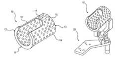
- FIG. 1is a perspective view of an embodiment of the plume shield shroud
- FIG. 2is a side planar view of the shroud shown in FIG. 1 ;
- FIG. 3is a first end view of the shroud shown in FIG. 1 ;
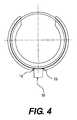
- FIG. 4is a second end view of the shroud shown in FIG. 1 ;
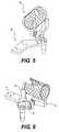
- FIG. 5is a top rear side perspective view of the plume shield shroud mounted to a mounting assembly
- FIG. 6is a top front side perspective view of the plume shield shroud and mounting assembly of FIG. 5 ;
- FIG. 7is a top and right side perspective view of a plume shield shroud and mounting assembly attached to a plasma gun.
- Laminar plasma plumeshave existed for some time in low pressure and reactor chambers, however the problems with ambient gas was not encountered in these situations.
- One aspect of the inventionrelates to a shroud for the laminar plasma plume.
- This shroudminimizes any potential forced interaction with air currents.
- the air currentsmight be caused, for example, by exhaust flow or gun motion.
- the shroudshields the plume starting approximately at the point the plume leaves the gun body to a predetermined distance past the location of powder injection into the plume. In a preferred embodiment, this distance is approximately one third the spray distance. In another embodiment, this distance is one half the spray distance. In still another embodiment, this distance is approximately one third to approximately one half the spray distance.
- the shroudis arranged as generally cylindrical.
- the length of the generally cylindrical shroudis similar to the lengths discussed above as the length of the shroud.
- the diameter of the generally cylindrical shroudis suitable to protect the plume. In an embodiment, the diameter of the generally cylindrical shroud is approximately 7 cm to approximately 10 cm.
- the shroudis made of any suitable material.
- the shroudis made of a metal, more preferably a high temperature metal that can withstand the heat of the plasma plume. Non-limiting examples of such materials are described below.
- the shroudis made of an open frame or perforated metal. This allows the plume to be viewed through the shroud.
- the shroudmay have approximately one third to one half of the surface area open with holes.
- the holes or openingsmay range from approximately 15 mm to approximately 50 mm in diameter. Larger holes may also be used but with reduced effectiveness. Use of a metal or wire mesh may also be used.
- the shroudhas a thermal barrier material or coating applied to the inside facing surface, i.e., the surface surrounding the gas plume. This thermal barrier contains the radiated heat and improves the thermal efficiency of the process.
- the shroudis mountable on a plasma gun. Additionally, the shroud, when mounted on a plasma gun, may also be pivotal and/or rotatable to allow full view of the plume or plume area when the gun is not in motion. This allows, for example, the taking of diagnostic measurements that would otherwise be blocked or interfered with by the shroud.
- the shroudmay use a two-layer shroud.
- an outer layer having a finer inner mesh inner layermay be used for additional resistance to penetration by air currents.
- an outer layer of the shroudis a perforated member and an inner layer of the shroud is a metal or wire mesh.
- an outer layer of the shroudis a wire or metal mesh and an inner layer of the shroud is a perforated member.
- both the outer and inner layers of the shroudare a perforated member.
- both the outer and inner layers of the shroudare a metal or wire mesh.
- FIGS. 1-4show non-limiting aspects of the invention
- FIGS. 5 and 6show a non-limiting mounting assembly 20 to which the shroud 10 can be mounted
- FIG. 7shows a non-limiting way in which the assembly 10 / 20 can be mounted to a plasma gun 30 .
- FIGS. 1-4show details of the plume shield shroud 10 in accordance with the invention.
- the shroud 10has a first end 11 and a second end 13 .
- the first end 11is open and includes a shroud ring member 12 secured thereto.
- the ring 12is secured to the first end 11 via welding. Other joining techniques may also be utilized.
- the ring 12has an annular portion whose inner edge 12 b is sized to be smaller than an inside diameter of a main section 14 of the shroud 10 and a circumferential portion 12 a sized and configured to receive therein or slide over the first end 11 .
- the section or main body 14is made of an open frame or a perforated metal. In accordance with a non-limiting embodiment, the outside diameter of the generally cylindrical body 14 is between approximately 7 cm and approximately 10 cm.
- the body 14is a tubular member and can be made of any suitable material.
- the body 14is made of a metal and more preferably a high temperature metal that can withstand the heat of a plasma plume.
- the body 14 materialmay be or include any of the following materials; steel; stainless steel; copper; inconel; high temperature nickel, chromium and/or cobalt based alloys; other metal families and alloys that can withstand tempts of up to 1500 degrees C. or more. Ceramics may also be used, for example, aluminum oxide.
- the body 14utilizes or includes a thermal barrier material or coating applied to the inside facing surface, i.e., the surface surrounding the gas plume.
- the body 14is perforated with the perforations 15 being of any size and/or shape.
- the holes or openings 15may range from approximately 15 mm to approximately 50 mm in diameter.
- the shapemay be, for example, circular, partially circular, polygons, partially polygonal, irregular in shape, as well as any shape that includes curved or linear sections or mixtures thereof. Additionally, artistic designs may be incorporated in the perforations and/or may result from their particular arrangement.
- the void to solid ratio of the body 14may be between about 5% and about 90%.
- the body 14is formed of a bent perforated sheet metal member which is bent into a generally tubular shape and which includes a main opening 16 which is sized and configured to receive therein a portion of the plasma gun such as a powder injection member.
- the opening 16allows the shroud 10 to pivot into and out of the gas plume shielding position shown in FIG. 7 .
- a seam 17(which can be connected by, e.g., welding) is utilized to join ends of the bent member so that section or body 14 retains its tubular shape.
- the shroud 10includes a mounting bar 18 which is fixed or secured to the body 14 via connections 19 .
- the connections 19are formed by welding.
- Member 18(as well as member 12 ) can be made of the same or similar materials as those used in making the body 14 .
- shroud 10While a cylindrical shape of the shroud 10 is preferred, other tubular shapes may be used, for example, generally oval in cross section, square or rectangular in cross section, as well as having triangular cross section, n-sided polygonal cross section, irregular cross section, a clover leaf cross section, and the like.
- the body 14may also be a weave of metal strands or metal fibers (not shown).
- a woven shroud 10may have a predetermined void to solid ratio of between about 5% to about 75%. This mesh may be regular or irregular or combinations thereof.
- the mounting assembly 20includes a mounting plate 21 which includes plural mounting openings and which can be mounted to a plasma gun 30 using, e.g., fasteners such as screw fasteners. Other mechanisms may also be utilized whether they allow for a non-removable mounting or a removable mounting.
- the mounting assembly 20also includes a mounting member 23 which includes plural mounting openings and which can be connected to the mounting bar 18 using, e.g., fasteners such as screw fasteners. Other mechanisms may also be utilized whether they allow for a non-removable mounting or a removable mounting.
- the mounting assembly 20additionally includes a pivoting shaft 22 which connects the mounting member 23 to a lever 24 which can be moved by a user from a use position, i.e., shown in FIG. 7 , to a downward position wherein the shroud 10 no longer surrounds the gas plume (not shown) or a gas plume area.
- a pivoting shaft 22which connects the mounting member 23 to a lever 24 which can be moved by a user from a use position, i.e., shown in FIG. 7 , to a downward position wherein the shroud 10 no longer surrounds the gas plume (not shown) or a gas plume area.
- an arrangementis utilized to non-movably retain the shroud 10 in each of these two positions.
- Such an arrangementcan include the spring shown in FIGS. 5 and 6 .
- members 21 - 24can be made of the same or similar materials as those used in making the member 18 .
- FIG. 7illustrates an embodiment for mounting the mounting assembly 20 , and thereby the shroud 10 , to a plasma gun 30 .
- the mounting assembly 20is secured to a bottom surface of the plasma gun 30 so that the shroud 10 can assume the use position shown in FIG. 7 when a central axis of the shroud 10 is oriented generally parallel to the bottom surface. In this position, a majority of the gas plume (not shown) is confined within the shroud 10 .
- the lever 24see FIGS.
Landscapes
- Engineering & Computer Science (AREA)
- Physics & Mathematics (AREA)
- Plasma & Fusion (AREA)
- Mechanical Engineering (AREA)
- Spectroscopy & Molecular Physics (AREA)
- Plasma Technology (AREA)
- Arc Welding In General (AREA)
- Coating By Spraying Or Casting (AREA)
Abstract
Description
Claims (19)
Priority Applications (1)
| Application Number | Priority Date | Filing Date | Title |
|---|---|---|---|
| US13/575,240US8941025B2 (en) | 2010-01-26 | 2011-01-25 | Plume shroud for laminar plasma guns |
Applications Claiming Priority (4)
| Application Number | Priority Date | Filing Date | Title |
|---|---|---|---|
| US29836610P | 2010-01-26 | 2010-01-26 | |
| US61298366 | 2010-01-26 | ||
| US13/575,240US8941025B2 (en) | 2010-01-26 | 2011-01-25 | Plume shroud for laminar plasma guns |
| PCT/US2011/022449WO2011094224A1 (en) | 2010-01-26 | 2011-01-25 | Plume shroud for laminar plasma guns |
Publications (2)
| Publication Number | Publication Date |
|---|---|
| US20120298217A1 US20120298217A1 (en) | 2012-11-29 |
| US8941025B2true US8941025B2 (en) | 2015-01-27 |
Family
ID=44319723
Family Applications (1)
| Application Number | Title | Priority Date | Filing Date |
|---|---|---|---|
| US13/575,240Expired - Fee RelatedUS8941025B2 (en) | 2010-01-26 | 2011-01-25 | Plume shroud for laminar plasma guns |
Country Status (5)
| Country | Link |
|---|---|
| US (1) | US8941025B2 (en) |
| EP (1) | EP2528706A4 (en) |
| JP (1) | JP5841070B2 (en) |
| CA (1) | CA2785781A1 (en) |
| WO (1) | WO2011094224A1 (en) |
Families Citing this family (4)
| Publication number | Priority date | Publication date | Assignee | Title |
|---|---|---|---|---|
| DE102012107282A1 (en) | 2012-01-17 | 2013-07-18 | Reinhausen Plasma Gmbh | DEVICE AND METHOD FOR PLASMA TREATMENT OF SURFACES |
| CN105689872B (en)* | 2015-12-16 | 2018-04-20 | 中国人民解放军第五七一九工厂 | Thin-wall annular part surface wear restorative procedure and its auxiliary device |
| USD824966S1 (en) | 2016-10-14 | 2018-08-07 | Oerlikon Metco (Us) Inc. | Powder injector |
| USD823906S1 (en) | 2017-04-13 | 2018-07-24 | Oerlikon Metco (Us) Inc. | Powder injector |
Citations (35)
| Publication number | Priority date | Publication date | Assignee | Title |
|---|---|---|---|---|
| US3217133A (en)* | 1962-02-14 | 1965-11-09 | Saint Gobain | Plasma torch |
| US3235705A (en)* | 1963-07-19 | 1966-02-15 | Air Reduction | Vertical welding |
| US3312810A (en)* | 1964-03-17 | 1967-04-04 | Omark Industries Inc | Automatic stud feeder |
| US3888422A (en) | 1974-02-08 | 1975-06-10 | Dayco Corp | Air gun |
| US4415795A (en)* | 1981-05-12 | 1983-11-15 | Union Carbide Canada Limited | Torch support and height sensor apparatus for shape cutting machines |
| US4707585A (en)* | 1986-03-17 | 1987-11-17 | Cincinnati Milacron Inc. | Laser wrist with sealed beam pathway |
| US4714513A (en)* | 1984-04-09 | 1987-12-22 | Mcalister Roy E | Apparatus for fushion welding plastic pipe joints |
| US4714860A (en)* | 1985-01-30 | 1987-12-22 | Brown Ian G | Ion beam generating apparatus |
| US4780591A (en)* | 1986-06-13 | 1988-10-25 | The Perkin-Elmer Corporation | Plasma gun with adjustable cathode |
| US4869936A (en)* | 1987-12-28 | 1989-09-26 | Amoco Corporation | Apparatus and process for producing high density thermal spray coatings |
| US5084603A (en)* | 1990-04-12 | 1992-01-28 | Societe Nationale D'etude Et De Construction De Moteurs D'aviation (S.N.E.C.M.) | Articulated protective shield for a welding head |
| US5285967A (en)* | 1992-12-28 | 1994-02-15 | The Weidman Company, Inc. | High velocity thermal spray gun for spraying plastic coatings |
| US5403399A (en)* | 1987-04-03 | 1995-04-04 | Fujitsu Limited | Method and apparatus for vapor deposition of diamond |
| US5519183A (en)* | 1993-09-29 | 1996-05-21 | Plasma-Technik Ag | Plasma spray gun head |
| US5579983A (en)* | 1994-08-19 | 1996-12-03 | Hitachi Zosen Corporation | Welding apparatus |
| US5624586A (en)* | 1995-01-04 | 1997-04-29 | Hypertherm, Inc. | Alignment device and method for a plasma arc torch system |
| US6149112A (en)* | 1997-03-28 | 2000-11-21 | Thieltges; Gary P. | Motion stable camera support system |
| US20030052095A1 (en)* | 2001-09-19 | 2003-03-20 | Hypertherm, Inc. | Plasma process and apparatus for cutting a cable |
| US6706993B1 (en)* | 2002-12-19 | 2004-03-16 | Ford Motor Company | Small bore PTWA thermal spraygun |
| US20040195213A1 (en)* | 2003-04-07 | 2004-10-07 | Angel Jeffrey R. | Pinch weld gun with swivel shunt connection |
| US6811812B2 (en)* | 2002-04-05 | 2004-11-02 | Delphi Technologies, Inc. | Low pressure powder injection method and system for a kinetic spray process |
| US20050048218A1 (en)* | 2003-08-29 | 2005-03-03 | Weidman Larry G. | Process for coating substrates with polymeric compositions |
| US20060289404A1 (en) | 2005-04-29 | 2006-12-28 | Sulzer Metco (Us), Inc. | Interchangeable plasma nozzle interface |
| US20070138147A1 (en)* | 2005-12-21 | 2007-06-21 | Sulzer Metco (Us), Inc. | Hybrid plasma-cold spray method and apparatus |
| US20070284340A1 (en)* | 2006-06-09 | 2007-12-13 | Morten Jorgensen | Vortex generator for plasma treatment |
| US7375301B1 (en)* | 2006-10-23 | 2008-05-20 | Majed Noujaim | Modular anode support member for plasma spray gun |
| US20090039059A1 (en)* | 2007-08-06 | 2009-02-12 | Hypertherm, Inc. | Articulated Thermal Processing Torch |
| US20090071944A1 (en)* | 2007-09-19 | 2009-03-19 | Murray Houlton Forlong | Torch spacing apparatus |
| US7557324B2 (en)* | 2002-09-18 | 2009-07-07 | Volvo Aero Corporation | Backstream-preventing thermal spraying device |
| US20090314202A1 (en)* | 2004-10-29 | 2009-12-24 | Zajchowski Paul H | Method and apparatus for microplasma spray coating a portion of a turbine vane in a gas turbine engine |
| US7644872B2 (en)* | 2006-03-23 | 2010-01-12 | United Technologies Corporation | Powder port blow-off for thermal spray processes |
| US20100096368A1 (en)* | 2005-07-14 | 2010-04-22 | Blankenship Donn R | Deposition apparatus and methods |
| US20100200549A1 (en)* | 2004-11-04 | 2010-08-12 | United Technologies Corporation | Microplasma Spray Apparatus and Method for Coating Articles Using Same |
| US8162239B2 (en)* | 2007-05-21 | 2012-04-24 | Thomas Francis Hursen | Air gun safety nozzle |
| US20120220138A1 (en)* | 2009-09-18 | 2012-08-30 | Otb Silar B.V. | Thin film deposition apparatus and method for the same |
Family Cites Families (2)
| Publication number | Priority date | Publication date | Assignee | Title |
|---|---|---|---|---|
| DE4228064A1 (en)* | 1992-08-24 | 1994-03-03 | Plasma Technik Ag | Plasma spray gun |
| US5637242A (en)* | 1994-08-04 | 1997-06-10 | Electro-Plasma, Inc. | High velocity, high pressure plasma gun |
- 2011
- 2011-01-25WOPCT/US2011/022449patent/WO2011094224A1/enactiveApplication Filing
- 2011-01-25EPEP11737524.6Apatent/EP2528706A4/ennot_activeWithdrawn
- 2011-01-25JPJP2012551237Apatent/JP5841070B2/ennot_activeExpired - Fee Related
- 2011-01-25CACA2785781Apatent/CA2785781A1/ennot_activeAbandoned
- 2011-01-25USUS13/575,240patent/US8941025B2/ennot_activeExpired - Fee Related
Patent Citations (37)
| Publication number | Priority date | Publication date | Assignee | Title |
|---|---|---|---|---|
| US3217133A (en)* | 1962-02-14 | 1965-11-09 | Saint Gobain | Plasma torch |
| US3235705A (en)* | 1963-07-19 | 1966-02-15 | Air Reduction | Vertical welding |
| US3312810A (en)* | 1964-03-17 | 1967-04-04 | Omark Industries Inc | Automatic stud feeder |
| US3888422A (en) | 1974-02-08 | 1975-06-10 | Dayco Corp | Air gun |
| US4415795A (en)* | 1981-05-12 | 1983-11-15 | Union Carbide Canada Limited | Torch support and height sensor apparatus for shape cutting machines |
| US4714513A (en)* | 1984-04-09 | 1987-12-22 | Mcalister Roy E | Apparatus for fushion welding plastic pipe joints |
| US4714860A (en)* | 1985-01-30 | 1987-12-22 | Brown Ian G | Ion beam generating apparatus |
| US4707585A (en)* | 1986-03-17 | 1987-11-17 | Cincinnati Milacron Inc. | Laser wrist with sealed beam pathway |
| US4780591A (en)* | 1986-06-13 | 1988-10-25 | The Perkin-Elmer Corporation | Plasma gun with adjustable cathode |
| US5403399A (en)* | 1987-04-03 | 1995-04-04 | Fujitsu Limited | Method and apparatus for vapor deposition of diamond |
| US4869936A (en)* | 1987-12-28 | 1989-09-26 | Amoco Corporation | Apparatus and process for producing high density thermal spray coatings |
| US5019429A (en)* | 1987-12-28 | 1991-05-28 | Amoco Corporation | High density thermal spray coating and process |
| US5084603A (en)* | 1990-04-12 | 1992-01-28 | Societe Nationale D'etude Et De Construction De Moteurs D'aviation (S.N.E.C.M.) | Articulated protective shield for a welding head |
| US5285967A (en)* | 1992-12-28 | 1994-02-15 | The Weidman Company, Inc. | High velocity thermal spray gun for spraying plastic coatings |
| US5519183A (en)* | 1993-09-29 | 1996-05-21 | Plasma-Technik Ag | Plasma spray gun head |
| US5579983A (en)* | 1994-08-19 | 1996-12-03 | Hitachi Zosen Corporation | Welding apparatus |
| US5624586A (en)* | 1995-01-04 | 1997-04-29 | Hypertherm, Inc. | Alignment device and method for a plasma arc torch system |
| US6149112A (en)* | 1997-03-28 | 2000-11-21 | Thieltges; Gary P. | Motion stable camera support system |
| US20030052095A1 (en)* | 2001-09-19 | 2003-03-20 | Hypertherm, Inc. | Plasma process and apparatus for cutting a cable |
| US6811812B2 (en)* | 2002-04-05 | 2004-11-02 | Delphi Technologies, Inc. | Low pressure powder injection method and system for a kinetic spray process |
| US7557324B2 (en)* | 2002-09-18 | 2009-07-07 | Volvo Aero Corporation | Backstream-preventing thermal spraying device |
| US6706993B1 (en)* | 2002-12-19 | 2004-03-16 | Ford Motor Company | Small bore PTWA thermal spraygun |
| US20040195213A1 (en)* | 2003-04-07 | 2004-10-07 | Angel Jeffrey R. | Pinch weld gun with swivel shunt connection |
| US20050048218A1 (en)* | 2003-08-29 | 2005-03-03 | Weidman Larry G. | Process for coating substrates with polymeric compositions |
| US20090314202A1 (en)* | 2004-10-29 | 2009-12-24 | Zajchowski Paul H | Method and apparatus for microplasma spray coating a portion of a turbine vane in a gas turbine engine |
| US20100200549A1 (en)* | 2004-11-04 | 2010-08-12 | United Technologies Corporation | Microplasma Spray Apparatus and Method for Coating Articles Using Same |
| US20060289404A1 (en) | 2005-04-29 | 2006-12-28 | Sulzer Metco (Us), Inc. | Interchangeable plasma nozzle interface |
| US20100096368A1 (en)* | 2005-07-14 | 2010-04-22 | Blankenship Donn R | Deposition apparatus and methods |
| US7582846B2 (en)* | 2005-12-21 | 2009-09-01 | Sulzer Metco (Us), Inc. | Hybrid plasma-cold spray method and apparatus |
| US20070138147A1 (en)* | 2005-12-21 | 2007-06-21 | Sulzer Metco (Us), Inc. | Hybrid plasma-cold spray method and apparatus |
| US7644872B2 (en)* | 2006-03-23 | 2010-01-12 | United Technologies Corporation | Powder port blow-off for thermal spray processes |
| US20070284340A1 (en)* | 2006-06-09 | 2007-12-13 | Morten Jorgensen | Vortex generator for plasma treatment |
| US7375301B1 (en)* | 2006-10-23 | 2008-05-20 | Majed Noujaim | Modular anode support member for plasma spray gun |
| US8162239B2 (en)* | 2007-05-21 | 2012-04-24 | Thomas Francis Hursen | Air gun safety nozzle |
| US20090039059A1 (en)* | 2007-08-06 | 2009-02-12 | Hypertherm, Inc. | Articulated Thermal Processing Torch |
| US20090071944A1 (en)* | 2007-09-19 | 2009-03-19 | Murray Houlton Forlong | Torch spacing apparatus |
| US20120220138A1 (en)* | 2009-09-18 | 2012-08-30 | Otb Silar B.V. | Thin film deposition apparatus and method for the same |
Also Published As
| Publication number | Publication date |
|---|---|
| US20120298217A1 (en) | 2012-11-29 |
| JP2013518393A (en) | 2013-05-20 |
| CA2785781A1 (en) | 2011-08-04 |
| EP2528706A4 (en) | 2017-08-02 |
| EP2528706A1 (en) | 2012-12-05 |
| JP5841070B2 (en) | 2016-01-06 |
| WO2011094224A1 (en) | 2011-08-04 |
Similar Documents
| Publication | Publication Date | Title |
|---|---|---|
| US8941025B2 (en) | Plume shroud for laminar plasma guns | |
| Li et al. | Effect of sprayed powder particle size on the oxidation behavior of MCrAlY materials during high velocity oxygen-fuel deposition | |
| JP4744692B2 (en) | Electrode having electron-emitting insert structure and manufacturing method thereof, and plasma arc torch having electrode having electron-emitting insert structure | |
| US20050199739A1 (en) | Method of forming metal coating with hvof spray gun and thermal spray apparatus | |
| CA2205681A1 (en) | Thermal spray gun with inner passage liner and component for such gun | |
| CN108890088A (en) | A kind of titanium alloy component vertical angle seam welding device | |
| JP2008043869A (en) | Thermal spraying device for forming supercooled liquid phase metal film | |
| JP2018507316A (en) | Plasma gun nozzle corrosion prevention and gun nozzle corrosion prevention method | |
| JP2003183805A (en) | Method of forming metal film by HVOF spray gun and spraying apparatus | |
| JP5865049B2 (en) | Apparatus and method for circuit protection | |
| KR101939850B1 (en) | A Torch Structure for MIG Welding Apparatus | |
| US9338873B1 (en) | Mesh screen assembly and shield cup for a gas shielded electric arc torch | |
| JP5565390B2 (en) | Method for manufacturing gas sensor element | |
| CN206405580U (en) | A kind of welding drags gas shield cover with tail | |
| CN109175633A (en) | A kind of welding protective device of titanium alloy component welding ring-shaped fillet weld | |
| JP2007136446A (en) | Plasma spray device and its electrode | |
| DE4339345C2 (en) | Process for applying a hard material layer by means of plasma spraying | |
| JP4685080B2 (en) | Arc welding torch | |
| CN107052544A (en) | Welding drags gas shield cover with tail | |
| JP4774510B2 (en) | Plasma deposition equipment | |
| US20160013021A1 (en) | Gas cooled plasma spraying device | |
| JPH11197841A (en) | Torch for narrow beveling welding, and narrow beveling welding method | |
| CN206405579U (en) | Welding drags gas shield cover with tail | |
| US5149932A (en) | Arc/gas electrode | |
| Castillon et al. | Analysis of Gas Metal Arc Welding (GMAW) regime transition in Ar-CO2/O2 shielding gases |
Legal Events
| Date | Code | Title | Description |
|---|---|---|---|
| AS | Assignment | Owner name:SULZER METCO (US) INC., NEW YORK Free format text:ASSIGNMENT OF ASSIGNORS INTEREST;ASSIGNORS:MCCULLOUGH, RICHARD;SPAULDING, MARK;SAVILL, ROBERT F., JR.;AND OTHERS;REEL/FRAME:026301/0034 Effective date:20110419 | |
| AS | Assignment | Owner name:SULZER METCO (US) INC., NEW YORK Free format text:ASSIGNMENT OF ASSIGNORS INTEREST;ASSIGNORS:MCCULLOUGH, RICHARD;SPAULDING, MARK;SAVILL, ROBERT F., JR;AND OTHERS;REEL/FRAME:028699/0337 Effective date:20110419 | |
| FEPP | Fee payment procedure | Free format text:PAYOR NUMBER ASSIGNED (ORIGINAL EVENT CODE: ASPN); ENTITY STATUS OF PATENT OWNER: LARGE ENTITY | |
| AS | Assignment | Owner name:OERLIKON METCO (US) INC., NEW YORK Free format text:CHANGE OF NAME;ASSIGNOR:SULZER METCO (US) INC.;REEL/FRAME:034628/0889 Effective date:20140630 | |
| STCF | Information on status: patent grant | Free format text:PATENTED CASE | |
| MAFP | Maintenance fee payment | Free format text:PAYMENT OF MAINTENANCE FEE, 4TH YEAR, LARGE ENTITY (ORIGINAL EVENT CODE: M1551) Year of fee payment:4 | |
| FEPP | Fee payment procedure | Free format text:MAINTENANCE FEE REMINDER MAILED (ORIGINAL EVENT CODE: REM.); ENTITY STATUS OF PATENT OWNER: LARGE ENTITY | |
| LAPS | Lapse for failure to pay maintenance fees | Free format text:PATENT EXPIRED FOR FAILURE TO PAY MAINTENANCE FEES (ORIGINAL EVENT CODE: EXP.); ENTITY STATUS OF PATENT OWNER: LARGE ENTITY | |
| STCH | Information on status: patent discontinuation | Free format text:PATENT EXPIRED DUE TO NONPAYMENT OF MAINTENANCE FEES UNDER 37 CFR 1.362 | |
| FP | Lapsed due to failure to pay maintenance fee | Effective date:20230127 |