US8940219B2 - Ophthalmic device formed by additive fabrication and method thereof - Google Patents
Ophthalmic device formed by additive fabrication and method thereofDownload PDFInfo
- Publication number
- US8940219B2 US8940219B2US12/341,067US34106708AUS8940219B2US 8940219 B2US8940219 B2US 8940219B2US 34106708 AUS34106708 AUS 34106708AUS 8940219 B2US8940219 B2US 8940219B2
- Authority
- US
- United States
- Prior art keywords
- lamina
- ophthalmic device
- droplets
- depositing
- microns
- Prior art date
- Legal status (The legal status is an assumption and is not a legal conclusion. Google has not performed a legal analysis and makes no representation as to the accuracy of the status listed.)
- Active, expires
Links
- 238000000034methodMethods0.000titleclaimsabstractdescription44
- 238000004519manufacturing processMethods0.000titleclaimsabstractdescription29
- 239000000654additiveSubstances0.000titleclaimsabstractdescription18
- 230000000996additive effectEffects0.000titleclaimsabstractdescription18
- 230000003287optical effectEffects0.000claimsabstractdescription33
- 238000000151depositionMethods0.000claimsabstractdescription26
- 230000004936stimulating effectEffects0.000claimsabstractdescription8
- 239000000463materialSubstances0.000claimsdescription28
- 230000002195synergetic effectEffects0.000claimsdescription17
- 230000000638stimulationEffects0.000claimsdescription10
- 239000000203mixtureSubstances0.000claimsdescription7
- 239000007788liquidSubstances0.000claimsdescription4
- 230000005855radiationEffects0.000claimsdescription4
- 125000004469siloxy groupChemical group[SiH3]O*0.000claims1
- 230000003746surface roughnessEffects0.000abstractdescription15
- 125000003118aryl groupChemical group0.000description15
- KPUWHANPEXNPJT-UHFFFAOYSA-NdisiloxaneChemical class[SiH3]O[SiH3]KPUWHANPEXNPJT-UHFFFAOYSA-N0.000description7
- 239000011230binding agentSubstances0.000description6
- 239000000126substanceSubstances0.000description6
- 238000010304firingMethods0.000description5
- 239000011344liquid materialSubstances0.000description5
- 230000015572biosynthetic processEffects0.000description4
- 239000011236particulate materialSubstances0.000description4
- 229920001296polysiloxanePolymers0.000description4
- 239000002243precursorSubstances0.000description4
- 238000011960computer-aided designMethods0.000description3
- 230000008021depositionEffects0.000description3
- 229920000642polymerPolymers0.000description3
- -1polysiloxanePolymers0.000description3
- CURLTUGMZLYLDI-UHFFFAOYSA-NCarbon dioxideChemical compoundO=C=OCURLTUGMZLYLDI-UHFFFAOYSA-N0.000description2
- 230000001133accelerationEffects0.000description2
- 238000009825accumulationMethods0.000description2
- 230000008901benefitEffects0.000description2
- 238000010586diagramMethods0.000description2
- 230000009969flowable effectEffects0.000description2
- 238000012986modificationMethods0.000description2
- 230000004048modificationEffects0.000description2
- 239000000178monomerSubstances0.000description2
- 125000001181organosilyl groupChemical group[SiH3]*0.000description2
- 238000012876topographyMethods0.000description2
- VAYTZRYEBVHVLE-UHFFFAOYSA-N1,3-dioxol-2-oneChemical compoundO=C1OC=CO1VAYTZRYEBVHVLE-UHFFFAOYSA-N0.000description1
- 241000209140TriticumSpecies0.000description1
- 235000021307TriticumNutrition0.000description1
- 238000000137annealingMethods0.000description1
- 229910002092carbon dioxideInorganic materials0.000description1
- 239000001569carbon dioxideSubstances0.000description1
- 239000002537cosmeticSubstances0.000description1
- 238000011161developmentMethods0.000description1
- 230000005670electromagnetic radiationEffects0.000description1
- 239000000017hydrogelSubstances0.000description1
- 239000002245particleSubstances0.000description1
- 229920000734polysilsesquioxane polymerPolymers0.000description1
- 239000000843powderSubstances0.000description1
- 239000012254powdered materialSubstances0.000description1
- 238000011160researchMethods0.000description1
- 230000001225therapeutic effectEffects0.000description1
- 229920001169thermoplasticPolymers0.000description1
- 239000004416thermosoftening plasticSubstances0.000description1
- 238000013519translationMethods0.000description1
Images


Classifications
- G—PHYSICS
- G02—OPTICS
- G02C—SPECTACLES; SUNGLASSES OR GOGGLES INSOFAR AS THEY HAVE THE SAME FEATURES AS SPECTACLES; CONTACT LENSES
- G02C7/00—Optical parts
- G02C7/02—Lenses; Lens systems ; Methods of designing lenses
- G02C7/04—Contact lenses for the eyes
- G—PHYSICS
- G02—OPTICS
- G02C—SPECTACLES; SUNGLASSES OR GOGGLES INSOFAR AS THEY HAVE THE SAME FEATURES AS SPECTACLES; CONTACT LENSES
- G02C7/00—Optical parts
- G02C7/02—Lenses; Lens systems ; Methods of designing lenses
- G02C7/04—Contact lenses for the eyes
- G02C7/049—Contact lenses having special fitting or structural features achieved by special materials or material structures
- B—PERFORMING OPERATIONS; TRANSPORTING
- B29—WORKING OF PLASTICS; WORKING OF SUBSTANCES IN A PLASTIC STATE IN GENERAL
- B29D—PRODUCING PARTICULAR ARTICLES FROM PLASTICS OR FROM SUBSTANCES IN A PLASTIC STATE
- B29D11/00—Producing optical elements, e.g. lenses or prisms
- B29D11/00009—Production of simple or compound lenses
- B29D11/00038—Production of contact lenses
- B—PERFORMING OPERATIONS; TRANSPORTING
- B29—WORKING OF PLASTICS; WORKING OF SUBSTANCES IN A PLASTIC STATE IN GENERAL
- B29D—PRODUCING PARTICULAR ARTICLES FROM PLASTICS OR FROM SUBSTANCES IN A PLASTIC STATE
- B29D11/00—Producing optical elements, e.g. lenses or prisms
- B29D11/0073—Optical laminates
- G—PHYSICS
- G02—OPTICS
- G02C—SPECTACLES; SUNGLASSES OR GOGGLES INSOFAR AS THEY HAVE THE SAME FEATURES AS SPECTACLES; CONTACT LENSES
- G02C7/00—Optical parts
- G02C7/02—Lenses; Lens systems ; Methods of designing lenses
- G02C7/022—Ophthalmic lenses having special refractive features achieved by special materials or material structures
- A—HUMAN NECESSITIES
- A61—MEDICAL OR VETERINARY SCIENCE; HYGIENE
- A61F—FILTERS IMPLANTABLE INTO BLOOD VESSELS; PROSTHESES; DEVICES PROVIDING PATENCY TO, OR PREVENTING COLLAPSING OF, TUBULAR STRUCTURES OF THE BODY, e.g. STENTS; ORTHOPAEDIC, NURSING OR CONTRACEPTIVE DEVICES; FOMENTATION; TREATMENT OR PROTECTION OF EYES OR EARS; BANDAGES, DRESSINGS OR ABSORBENT PADS; FIRST-AID KITS
- A61F2/00—Filters implantable into blood vessels; Prostheses, i.e. artificial substitutes or replacements for parts of the body; Appliances for connecting them with the body; Devices providing patency to, or preventing collapsing of, tubular structures of the body, e.g. stents
- A61F2/02—Prostheses implantable into the body
- A61F2/14—Eye parts, e.g. lenses or corneal implants; Artificial eyes
- A61F2/16—Intraocular lenses
- A—HUMAN NECESSITIES
- A61—MEDICAL OR VETERINARY SCIENCE; HYGIENE
- A61F—FILTERS IMPLANTABLE INTO BLOOD VESSELS; PROSTHESES; DEVICES PROVIDING PATENCY TO, OR PREVENTING COLLAPSING OF, TUBULAR STRUCTURES OF THE BODY, e.g. STENTS; ORTHOPAEDIC, NURSING OR CONTRACEPTIVE DEVICES; FOMENTATION; TREATMENT OR PROTECTION OF EYES OR EARS; BANDAGES, DRESSINGS OR ABSORBENT PADS; FIRST-AID KITS
- A61F2240/00—Manufacturing or designing of prostheses classified in groups A61F2/00 - A61F2/26 or A61F2/82 or A61F9/00 or A61F11/00 or subgroups thereof
- A61F2240/001—Designing or manufacturing processes
- B—PERFORMING OPERATIONS; TRANSPORTING
- B33—ADDITIVE MANUFACTURING TECHNOLOGY
- B33Y—ADDITIVE MANUFACTURING, i.e. MANUFACTURING OF THREE-DIMENSIONAL [3-D] OBJECTS BY ADDITIVE DEPOSITION, ADDITIVE AGGLOMERATION OR ADDITIVE LAYERING, e.g. BY 3-D PRINTING, STEREOLITHOGRAPHY OR SELECTIVE LASER SINTERING
- B33Y10/00—Processes of additive manufacturing
- B—PERFORMING OPERATIONS; TRANSPORTING
- B33—ADDITIVE MANUFACTURING TECHNOLOGY
- B33Y—ADDITIVE MANUFACTURING, i.e. MANUFACTURING OF THREE-DIMENSIONAL [3-D] OBJECTS BY ADDITIVE DEPOSITION, ADDITIVE AGGLOMERATION OR ADDITIVE LAYERING, e.g. BY 3-D PRINTING, STEREOLITHOGRAPHY OR SELECTIVE LASER SINTERING
- B33Y80/00—Products made by additive manufacturing
- G—PHYSICS
- G02—OPTICS
- G02C—SPECTACLES; SUNGLASSES OR GOGGLES INSOFAR AS THEY HAVE THE SAME FEATURES AS SPECTACLES; CONTACT LENSES
- G02C2202/00—Generic optical aspects applicable to one or more of the subgroups of G02C7/00
- G02C2202/16—Laminated or compound lenses
Definitions
- This inventionrelates to the formation of three dimensional objects using additive fabrication techniques. More specifically, the invention relates to an ophthalmic device which is formed by additive fabrication and a method of making the same.
- RP&Mrapid prototyping and manufacturing
- a first known technique for making three dimensional objectsis by applying successive layers of unsolidified, fluid-like material to a working surface. The layers are then selectively solidified according to cross-sectional computer data representing the object.
- These solidified layers, or laminaeare typically formed of a photo polymer liquid material and solidified via visible or ultraviolet electromagnetic radiation from a laser. More specifically, his technique involves applying liquid material to areas which will, and which will not, be part of the finished three dimensional object. The radiation is then used to solidify only those areas that are part of the three dimensional object. Often referred to as stereolithography, this technique is known and disclosed in several patents and patent applications, for example, U.S. Pat. No. 4,575,330 to Hull. Similarly, layers of a powered material can be selectively solidified by depositing a chemical binder material thereon.
- a third technique used for RP&Mis laminated object manufacturing.
- three dimensional objectsare formed by stacking sheets of material together wherein each sheet is adhered to another. The stacked sheets are then selectively cut in a particular order to form the desired three dimensional object, according to computer data representing the cross-sectional slices of the three dimensional object.
- Ophthalmic devicesrequire a surface variation or roughness in the optical surface that is less than approximately 10 microns and typically less than two microns and preferably less than one micron.
- ophthalmic deviceusing additive formation techniques, wherein the ophthalmic device has a surface variation or roughness on the order of less than 10 microns and in select configurations less than two microns and in certain configurations less than one micron (submicron).
- the present disclosurebroadly comprises an ophthalmic device having an optical surface formed by additive fabrication, wherein the optical surface has a surface roughness of less than 10 microns, and in select configurations less than 2 microns, and preferably less than one micron.
- the present disclosurefurther comprises a method of making an ophthalmic device having an optical surface by depositing on a stage in a first relative position a first lamina of particulates having a size less than 10 microns and in select configurations less than 2 microns and in certain configurations less than one micron, and synergistically stimulating the first lamina of particulates to form a first solidified layer, a portion of the layer forming a portion of the optical surface.
- the present disclosurealso comprises a method of forming an ophthalmic device comprising depositing by additive fabrication a plurality of bonded laminae to define an optical surface, the lamina having a thickness of less than 10 microns, and in select configurations less than 2 microns and in certain configurations less than one micron.
- An object of the disclosureis to provide an ophthalmic device having an optical surface with surface roughness less than 10 microns, and in select configurations less than 2 microns and in certain configurations less than one micron, the optical surface formed by additive fabrication.
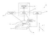
- FIG. 1is a schematic diagram of main functional components of an additive fabrication apparatus
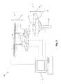
- FIG. 2is a perspective view of the main functional components of the additive fabrication apparatus
- FIG. 3is a flow chart diagram illustrating the build-up of the ophthalmic device of FIG. 1 .
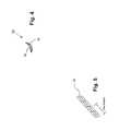
- FIG. 4is a perspective view of laminae of an ophthalmic device.
- FIG. 5is a partial cross-sectional view of an ophthalmic device.
- FIGS. 1 and 2depict a schematic representation of an additive fabrication apparatus 10 for use in making ophthalmic devices 12 .
- the additive fabrication apparatus 10includes cross-sectional computer data 14 of a three-dimensional object which is transferred to a computer system comprising a machine controller 16 .
- the cross-sectional computer data 14can be created in a typical computer aided design (CAD) system, wherein a user creates an ophthalmic device which can be saved as a data file containing coordinate information corresponding to cross-sectional slices of the ophthalmic device 12 .
- CADcomputer aided design
- Such method and apparatus for slicing a three-dimensional objectis described in U.S. Pat. No. 5,854,748 to Snead et al., which is hereby incorporated by reference.
- This data file of the ophthalmic device 12is formed into coded binary information that is transferred to a machine controller 16 .
- the machine controller 16communicates with a dispensing head 18 and a stage 20 arranged to support the ophthalmic device 12 being formed.
- the dispensing head 18is connected to a dispensing head positioner 22 , wherein the dispensing head 18 is selectively moveable in the X- and Y-axes by commands from the machine controller 16 .
- the dispensing head 18is also selectively moveable in the Z-axis. More preferably, the dispensing head 18 is moveable in any direction according to instructions received from the machine controller 16 .
- the dispensing head 18undergoes back and forth movements and accelerations, similar to commercial print head configurations used in typical three-dimensional modeling systems.
- the dispensing head 18may be any suitable ejection head having an ejection nozzle 24 for emitting small mass particulates or droplets of particulate material.
- the dispensing head 18ejects droplets that are less than 10 microns and in select configurations less than two microns and certain configurations less than one micron (submicron) in size.
- the dispensing head 18comprises an array of dispensing pins 26 arranged in the nozzle 24 which dispense a plurality of particulates according to the instructions received from the machine controller 16 .
- Each dispensing pin 26is individually controllable such that particulates may be dispensed from some, but not all of the pins 26 , according to the machine controller 16 instructions. Any suitable number of dispensing pins 26 may be utilized. Further, the pins 26 may be configured according to any preferred arrangement.
- the dispensing head 18can be configured similar to the droplet dispenser disclosed in U.S. Pat. No. 6,808,683 to Gilbert, which is hereby incorporated by reference.
- the nozzle 24may include orifices 28 capable of dispensing micron or submicron sized particulates as discussed in more detail below, wherein any optimal number of orifices 28 can be selected and arranged in a desired configuration.
- the particulatesare a chemical binder which adhere material in a powdered form.
- the refractive index of each materialshould be approximately the same, and more preferably identical.
- the dispensing head 18 utilizing orifices 28 capable of dispensing micron or submicron sized particulatespreferably includes an orifice plate 32 mounted on the dispensing portion of the dispensing head 18 .
- Each orifice 28is preferably equipped with a piezoelectric element that causes a pressure wave to propagate through the material when an electronic firing pulse is supplied to the element. The pressure wave causes the particulate material to be released from the orifice 28 .
- the machine controller 16determines the rate and timing of the firing pulse applied to each individual orifice 28 .
- the particulates dispensed from the dispensing head 18need to be accurately placed in a desired location so that the particulate layers, or laminae, can be built-up vertically.
- the desired locationis determined from the computer data providing a data map or pixel locations that identify the desired location.
- the dispensing head 18must be directed to a predetermined dispensing position by the dispensing head positioner 22 .
- the stage 20 for supporting the ophthalmic device 12can be directed to a predetermined stage position by a stage positioner 30 , wherein the stage position is related to the predetermined dispensing position at the particular time of firing of the material through the ejection nozzle 24 .
- the stage 20connected to the stage positioner 30 , is selectively moveable in the X and Y-axes by commands from the machine controller 16 . That is, in an embodiment of the invention, the stage 20 is moveable, horizontally and perpendicularly to the ground. In an embodiment of the invention, the stage 20 is also selectively moveable in the Z-axis. Although the stage 20 is preferably moveable along at least the Y-axis, movement of the stage 20 is not required at all since the dispensing head 18 can be moveable in all directions in a relative manner to the stage 20 .
- the machine controller 16selectively moves the stage 20 with micron or submicron motion control.
- Obtaining micron or submicron positioning of a stage in a high resolution systemis well known in the art and can be performed by commercially available or custom developed systems such as the DynamYX and the Mat350 submicron positioning systems of Kensington Laboratories of Richmond, Calif., the nano resolution linear stages of ALIO Industries of Wheat Ridge, Colo., the motion controllers and the NanoStepper of Baldor Electric Company of Fort Smith, Ark, the multi-axes, sub-micron positioner described in U.S. Pat. No. 6,888,289 to Heilig et al. which is hereby incorporated by reference, and the motion controllers of Galil Motion Control, Inc.
- raster scanningis used to position the dispensing head 18 having either pins 26 or orifices 28 at the desired firing locations. That is, the printing process for each lamina is accomplished by a series of relative movements between the dispensing head 18 and the desired firing locations. Printing typically occurs as the dispensing head 18 relatively moves in a main scanning direction. This is followed by a typically smaller increment of movement in a secondary scanning direction while no dispensing occurs, which in turn is followed by a reverse scan in the main scanning direction in which dispensing again occurs. The process of altering main scans and secondary scans occurs repeatedly until the laminae are completely deposited.
- Alternative embodimentsmay perform small secondary scanning movements while main scanning occurs. Because of the typically large difference in net scanning speed along the main and secondary directions, such an alternative still results in deposition along scanning lines which are nearly parallel to the main scanning direction and perpendicular to the secondary scanning direction. Further alternative preferred embodiments may utilize vector scanning techniques or a combination of vector scanning and raster scanning techniques.
- the additive fabrication apparatus 10further includes a synergistic stimulator 34 that causes the particulates dispensed from the dispensing head 22 to selectively harden.
- the synergistic stimulator 34is a ultra-violet (UV) laser which is capable of curing a liquid material.
- the synergistic stimulator 34can be infrared (IR) radiation from a carbon dioxide laser, which can selectively harden a sinterable powered.
- the synergistic stimulator 34can be a chemical binder which can adhere particulate powder upon selective application of the chemical binder.
- the additive fabrication apparatus 10builds an ophthalmic device 12 lamina-by-lamina to form an ophthalmic device 12 having an optical surface 36 shown in FIG. 4 , wherein the lamina have a thickness less than 10 microns and in select configurations less than two microns and certain configurations less than one micron (submicron) in size.
- Ophthalmic deviceis meant to include, but is not limited to, a device suitable for placement in the eye, for example, an intraocular lens (IOL) or a corrective, therapeutic or cosmetic contact lens.
- IOLintraocular lens
- a desired number of laminaeis determined (step 102 ) based on information obtained from the CAD data (step 100 ).
- the stage 20 and/or the dispensing head 18are directed to move by the machine controller 16 (step 104 ) and a lamina is dispensed (step 106 ).
- the nozzle 24is arranged in a predetermined position in relation to the stage 20 .
- the last-built laminais positioned proximate to the nozzle 24 allowing the next to-be-built lamina to be placed in a registered manner with the first lamina.
- the nozzle 24undergoes back and forth movements and accelerations until a new lamina is deposited on the last-built lamina.
- the particulatesare ejected therefrom.
- a sacrificial material 38can be used to support the laminae during the printing process. That is, to prevent the laminae from collapsing during formation, a wax-like material can be simultaneously or contemporaneously ejected from some of the orifices 28 or pins 26 of the nozzle 24 .
- the synergistic stimulator 34selectively hardens the lamina (step 108 ).
- UV radiationis used to cure the lamina.
- the synergistic stimulator 34can be a chemical binder ejected from the dispensing head 18 to adhere a powdered material.
- the machine controller 16determines whether the desired laminae number has been reached upon completion of the lamina deposit (step 110 ).
- next laminais formed in a registered manner with respect to the last-built lamina, wherein the dispensing head 18 and/or stage 20 are translated to align the dispensing head 18 with respect to the last-built lamina.
- This process of lamina depositing and synergistic stimulationis repeated until the desired number of laminae has been completed (step 112 ).
- the sacrificial material 38forms a working surface on which to build object lamina and even successive support lamina. Further, the sacrificial material 38 is easily removable from the optical surface 36 it supports. Also, when removed, only a minimal amount of damage to the optical surface 36 is incurred, which can be corrected by heat annealing as described in more detail below.
- vertical accumulation of the sacrificial material 38is important and, as such, it is desirable to have sacrificial material 38 built-up at approximately the same rate as the ophthalmic device 12 . Specifically, it is preferred that the vertical accumulation of the sacrificial material 38 accumulates at least as fast as the laminae defining the optical surface 36 .
- an additional optional stepcan be taken to assist in forming the desired micron or submicron optical surface roughness. That is, the ophthalmic device 12 can be heat annealed, thereby providing a resultant optical surface 36 having a surface roughness of one micron or less than one micron. This step is particularly useful when the optical surface 36 is damaged during the removal of sacrificial material 38 .
- the surface roughness of the ophthalmic deviceis a measure of amplitude of surface variations based on the vertical deviations of the roughness profile from a mean line.
- Rais the arithmetic average of the absolute values.
- the surface roughnesscan be defined as having an Ra of less than 10 microns and in select configurations less than two microns and certain configurations less than one micron (submicron).
- the surface roughnesscan be defined in terms of RMS (root mean square) as less than 10 microns and in select configurations less than two microns and certain configurations less than one micron (submicron).
- Surface finish, surface roughnessis usually specified based on the ASME Y14.36M-1996 standard.
Landscapes
- Health & Medical Sciences (AREA)
- Ophthalmology & Optometry (AREA)
- Engineering & Computer Science (AREA)
- Physics & Mathematics (AREA)
- General Health & Medical Sciences (AREA)
- Optics & Photonics (AREA)
- General Physics & Mathematics (AREA)
- Mechanical Engineering (AREA)
- Manufacturing & Machinery (AREA)
- Vascular Medicine (AREA)
- Animal Behavior & Ethology (AREA)
- Life Sciences & Earth Sciences (AREA)
- Public Health (AREA)
- Veterinary Medicine (AREA)
- Heart & Thoracic Surgery (AREA)
- Biomedical Technology (AREA)
- Transplantation (AREA)
- Oral & Maxillofacial Surgery (AREA)
- Cardiology (AREA)
Abstract
Description
Claims (19)
Priority Applications (5)
| Application Number | Priority Date | Filing Date | Title |
|---|---|---|---|
| US12/341,067US8940219B2 (en) | 2007-12-31 | 2008-12-22 | Ophthalmic device formed by additive fabrication and method thereof |
| US14/578,887US10139651B2 (en) | 2007-12-31 | 2014-12-22 | Ophthalmic device formed by additive fabrication and method thereof |
| US16/109,160US11287672B2 (en) | 2007-12-31 | 2018-08-22 | Ophthalmic device formed by additive fabrication and method thereof |
| US17/552,063US12135469B2 (en) | 2007-12-31 | 2021-12-15 | Ophthalmic device formed by additive fabrication and method thereof |
| US18/931,369US20250053027A1 (en) | 2007-12-31 | 2024-10-30 | Ophthalmic device formed by additive fabrication and method thereof |
Applications Claiming Priority (2)
| Application Number | Priority Date | Filing Date | Title |
|---|---|---|---|
| US1800907P | 2007-12-31 | 2007-12-31 | |
| US12/341,067US8940219B2 (en) | 2007-12-31 | 2008-12-22 | Ophthalmic device formed by additive fabrication and method thereof |
Related Child Applications (1)
| Application Number | Title | Priority Date | Filing Date |
|---|---|---|---|
| US14/578,887ContinuationUS10139651B2 (en) | 2007-12-31 | 2014-12-22 | Ophthalmic device formed by additive fabrication and method thereof |
Publications (2)
| Publication Number | Publication Date |
|---|---|
| US20090326651A1 US20090326651A1 (en) | 2009-12-31 |
| US8940219B2true US8940219B2 (en) | 2015-01-27 |
Family
ID=41448380
Family Applications (5)
| Application Number | Title | Priority Date | Filing Date |
|---|---|---|---|
| US12/341,067Active2032-02-26US8940219B2 (en) | 2007-12-31 | 2008-12-22 | Ophthalmic device formed by additive fabrication and method thereof |
| US14/578,887ActiveUS10139651B2 (en) | 2007-12-31 | 2014-12-22 | Ophthalmic device formed by additive fabrication and method thereof |
| US16/109,160Active2029-12-29US11287672B2 (en) | 2007-12-31 | 2018-08-22 | Ophthalmic device formed by additive fabrication and method thereof |
| US17/552,063ActiveUS12135469B2 (en) | 2007-12-31 | 2021-12-15 | Ophthalmic device formed by additive fabrication and method thereof |
| US18/931,369PendingUS20250053027A1 (en) | 2007-12-31 | 2024-10-30 | Ophthalmic device formed by additive fabrication and method thereof |
Family Applications After (4)
| Application Number | Title | Priority Date | Filing Date |
|---|---|---|---|
| US14/578,887ActiveUS10139651B2 (en) | 2007-12-31 | 2014-12-22 | Ophthalmic device formed by additive fabrication and method thereof |
| US16/109,160Active2029-12-29US11287672B2 (en) | 2007-12-31 | 2018-08-22 | Ophthalmic device formed by additive fabrication and method thereof |
| US17/552,063ActiveUS12135469B2 (en) | 2007-12-31 | 2021-12-15 | Ophthalmic device formed by additive fabrication and method thereof |
| US18/931,369PendingUS20250053027A1 (en) | 2007-12-31 | 2024-10-30 | Ophthalmic device formed by additive fabrication and method thereof |
Country Status (1)
| Country | Link |
|---|---|
| US (5) | US8940219B2 (en) |
Cited By (3)
| Publication number | Priority date | Publication date | Assignee | Title |
|---|---|---|---|---|
| US9910296B2 (en) | 2015-11-11 | 2018-03-06 | Onefocus Vision, Inc. | Accommodating lens with cavity |
| US20190143585A1 (en)* | 2017-11-13 | 2019-05-16 | General Electric Company | Additively manufactured vertical wall from slurry |
| US11982880B2 (en) | 2016-11-11 | 2024-05-14 | Onefocus Vision, Inc. | Accommodating cavity lens shaped with photocleavable insert |
Families Citing this family (9)
| Publication number | Priority date | Publication date | Assignee | Title |
|---|---|---|---|---|
| GB2487055B (en)* | 2011-01-05 | 2017-08-02 | The Manchester Metropolitan Univ | Artificial eyes and manufacture thereof |
| JP6002954B2 (en)* | 2012-01-20 | 2016-10-05 | 兵神装備株式会社 | 3D structure modeling equipment |
| WO2015197495A1 (en)* | 2014-06-27 | 2015-12-30 | Koninklijke Philips N.V. | Printing device and method for 3d printing |
| US20180001581A1 (en)* | 2015-01-14 | 2018-01-04 | Jayant K. Patel | Compositions, systems and methods for patient specific ophthalmic device |
| WO2018145114A1 (en) | 2017-02-06 | 2018-08-09 | Optimedica Corporation | Additive manufacturing inside the human eye |
| EP3473418B1 (en)* | 2017-10-19 | 2023-12-06 | Essilor International | Method for manufacturing an ophthalmic lens |
| IL275971B2 (en)* | 2018-01-11 | 2025-04-01 | E Vision Smart Optics Inc | Three-dimensional (3d) printing of electro-active lenses |
| US12285909B2 (en) | 2018-03-09 | 2025-04-29 | Northwestern University | High-throughput 3D printing of customized aspheric imaging lenses |
| CN110039806A (en)* | 2019-04-23 | 2019-07-23 | 首都医科大学附属北京同仁医院 | A kind of high-accuracy 3D printing method of personalized eye eyeglass |
Citations (33)
| Publication number | Priority date | Publication date | Assignee | Title |
|---|---|---|---|---|
| US4242381A (en)* | 1979-04-18 | 1980-12-30 | General Electric Company | Method of providing a polycarbonate article with a uniform and durable silica filled organopolysiloxane coating |
| US4575330A (en) | 1984-08-08 | 1986-03-11 | Uvp, Inc. | Apparatus for production of three-dimensional objects by stereolithography |
| US5204055A (en) | 1989-12-08 | 1993-04-20 | Massachusetts Institute Of Technology | Three-dimensional printing techniques |
| US5316791A (en)* | 1993-01-21 | 1994-05-31 | Sdc Coatings Inc. | Process for improving impact resistance of coated plastic substrates |
| US5362427A (en) | 1993-05-10 | 1994-11-08 | Mitchell Jr Porter H | Method and apparatus for manufacturing an article using a support structure for supporting an article during manufacture therefor |
| US5386500A (en) | 1987-06-02 | 1995-01-31 | Cubital Ltd. | Three dimensional modeling apparatus |
| US5387380A (en)* | 1989-12-08 | 1995-02-07 | Massachusetts Institute Of Technology | Three-dimensional printing techniques |
| US5398193A (en) | 1993-08-20 | 1995-03-14 | Deangelis; Alfredo O. | Method of three-dimensional rapid prototyping through controlled layerwise deposition/extraction and apparatus therefor |
| US5510066A (en) | 1992-08-14 | 1996-04-23 | Guild Associates, Inc. | Method for free-formation of a free-standing, three-dimensional body |
| US5854748A (en) | 1988-04-18 | 1998-12-29 | 3D Systems, Inc. | Boolean layer comparison slice |
| US6136252A (en) | 1995-09-27 | 2000-10-24 | 3D Systems, Inc. | Apparatus for electro-chemical deposition with thermal anneal chamber |
| US6406658B1 (en) | 1999-02-08 | 2002-06-18 | 3D Systems, Inc. | Stereolithographic method and apparatus for production of three dimensional objects using multiple beams of different diameters |
| US6508971B2 (en) | 1995-09-27 | 2003-01-21 | 3D Systems, Inc. | Selective deposition modeling method and apparatus for forming three-dimensional objects and supports |
| US20040046287A1 (en)* | 2002-09-06 | 2004-03-11 | Andino Rafael Victor | Method for making opthalmic devices |
| US6808683B2 (en) | 2001-09-25 | 2004-10-26 | Cytonome, Inc. | Droplet dispensing system |
| US6864342B2 (en) | 2001-11-02 | 2005-03-08 | Bausch & Lomb Incorporated | High refractive index aromatic-based prepolymers |
| US6864341B2 (en) | 2001-11-02 | 2005-03-08 | Bausch & Lomb Incorporated | High refractive index aromatic-based prepolymer precursors |
| US6881809B2 (en) | 2001-11-02 | 2005-04-19 | Bausch & Lomb Incorporated | High refractive index aromatic-based silyl monomers |
| US6881808B2 (en) | 2001-11-02 | 2005-04-19 | Bausch & Lomb Incorporated | High refractive index aromatic-based siloxane difunctional macromonomers |
| US6888289B2 (en) | 2002-07-16 | 2005-05-03 | Baldor Electric Company | Multi-axes, sub-micron positioner |
| US6891010B2 (en) | 2001-10-29 | 2005-05-10 | Bausch & Lomb Incorporated | Silicone hydrogels based on vinyl carbonate endcapped fluorinated side chain polysiloxanes |
| US6906162B2 (en) | 2001-11-02 | 2005-06-14 | Bausch & Lomb Incorporated | High refractive index aromatic-based siloxane monofunctional macromonomers |
| US6908978B2 (en) | 2001-11-02 | 2005-06-21 | Bausch & Lomb Incorporated | High refractive index polymeric siloxysilane compositions |
| US6911173B2 (en)* | 2001-08-30 | 2005-06-28 | Micron Technology, Inc. | Methods for stereolithographic processing of components and assemblies |
| US6956087B2 (en) | 2002-12-13 | 2005-10-18 | Bausch & Lomb Incorporated | High refractive index polysiloxane prepolymers |
| US7169874B2 (en) | 2001-11-02 | 2007-01-30 | Bausch & Lomb Incorporated | High refractive index polymeric siloxysilane compositions |
| US7176268B2 (en) | 2003-12-05 | 2007-02-13 | Bausch & Lomb Incorporated | Prepolymers for improved surface modification of contact lenses |
| US7198639B2 (en) | 2002-09-13 | 2007-04-03 | Bausch & Lomb Incorporated | Polysilsesquioxane containing polymeric compositions |
| US7209797B2 (en) | 2002-01-03 | 2007-04-24 | Objet Geometries Ltd. | System and method for accurate printing of three dimensional models utilizing adjustment parameters |
| US20070103639A1 (en) | 2003-07-11 | 2007-05-10 | Koninklijke Philips Electronics N.V. | Method of manufacturing a mould for producing an optical surface, a method of producing a contact lens and a device for use with these methods |
| US7229594B2 (en) | 2000-04-03 | 2007-06-12 | Parabol Technologies S.A. | Device for dispensing accurately-controlled small doses of liquid |
| US7279538B2 (en) | 2005-04-01 | 2007-10-09 | Bausch & Lomb Incorporated | Aromatic-based polysiloxane prepolymers and ophthalmic devices produced therefrom |
| US7297160B2 (en) | 2005-06-15 | 2007-11-20 | Bausch & Lomb Incorporated | High refractive-index, hydrophilic, arylsiloxy-containing macromonomers and polymers, and ophthalmic devices comprising such polymers |
Family Cites Families (21)
| Publication number | Priority date | Publication date | Assignee | Title |
|---|---|---|---|---|
| US3986997A (en)* | 1974-06-25 | 1976-10-19 | Dow Corning Corporation | Pigment-free coating compositions |
| EP0458734B1 (en) | 1990-04-24 | 1993-12-01 | Ciba-Geigy Ag | Process for the production of contact lenses |
| JP3724893B2 (en) | 1996-09-25 | 2005-12-07 | ナブテスコ株式会社 | Optical three-dimensional molding resin composition |
| US6196685B1 (en) | 1999-04-02 | 2001-03-06 | Johnson & Johnson Vision Care, Inc. | Method of designing and fitting multifocal lenses taking into account material properties of the lenses |
| AU5871500A (en)* | 1999-06-11 | 2001-01-02 | Sydney Hyman | Image making medium |
| AU782256B2 (en) | 1999-11-01 | 2005-07-14 | Praful Doshi | Tinted lenses and methods of manufacture |
| AU2002220570A1 (en) | 2000-09-28 | 2002-04-08 | Novartis Pharma Gmbh | Fenestrated lens for increased tear flow and method for making the same |
| US6811805B2 (en)* | 2001-05-30 | 2004-11-02 | Novatis Ag | Method for applying a coating |
| US7632540B2 (en) | 2003-07-01 | 2009-12-15 | Transitions Optical, Inc. | Alignment facilities for optical dyes |
| US7256921B2 (en)* | 2003-07-01 | 2007-08-14 | Transitions Optical, Inc. | Polarizing, photochromic devices and methods of making the same |
| US20050074616A1 (en) | 2003-10-02 | 2005-04-07 | John Harchanko | Lithographic method for forming mold inserts and molds |
| US7188950B2 (en) | 2003-11-14 | 2007-03-13 | Ophthonix, Inc. | Eyeglass dispensing method |
| EP1855622B1 (en) | 2005-02-01 | 2020-10-14 | Timothy P. Friel | Fabrication method of an ocular prosthesis |
| DE102005033746A1 (en) | 2005-07-15 | 2007-01-25 | Schott Ag | Compact lens for e.g. cell phone camera, has diffractive optical element imaging incident light, and refractive optical element provided as compound lens with lens elements having two indices of refraction, respectively |
| US20070141114A1 (en)* | 2005-12-15 | 2007-06-21 | Essilor International Compagnie Generale D'optique | Article coated with an ultra high hydrophobic film and process for obtaining same |
| DE102006012225A1 (en) | 2006-03-16 | 2007-09-20 | Fraunhofer-Gesellschaft zur Förderung der angewandten Forschung e.V. | Optical element, process for its preparation and apparatus for carrying out the process |
| WO2008033481A2 (en) | 2006-09-13 | 2008-03-20 | Praful Doshi | Tinted lenses and methods of manufacture |
| US7735998B2 (en)* | 2006-10-25 | 2010-06-15 | Volk Donald A | Multi-layered multifocal lens with blended refractive index |
| US20080273073A1 (en) | 2007-05-01 | 2008-11-06 | Gentex Optics, Inc. | System and method for application of ink formulations onto ophthalmic lenses |
| US8317505B2 (en) | 2007-08-21 | 2012-11-27 | Johnson & Johnson Vision Care, Inc. | Apparatus for formation of an ophthalmic lens precursor and lens |
| US7802883B2 (en) | 2007-12-20 | 2010-09-28 | Johnson & Johnson Vision Care, Inc. | Cosmetic contact lenses having a sparkle effect |
- 2008
- 2008-12-22USUS12/341,067patent/US8940219B2/enactiveActive
- 2014
- 2014-12-22USUS14/578,887patent/US10139651B2/enactiveActive
- 2018
- 2018-08-22USUS16/109,160patent/US11287672B2/enactiveActive
- 2021
- 2021-12-15USUS17/552,063patent/US12135469B2/enactiveActive
- 2024
- 2024-10-30USUS18/931,369patent/US20250053027A1/enactivePending
Patent Citations (48)
| Publication number | Priority date | Publication date | Assignee | Title |
|---|---|---|---|---|
| US4242381A (en)* | 1979-04-18 | 1980-12-30 | General Electric Company | Method of providing a polycarbonate article with a uniform and durable silica filled organopolysiloxane coating |
| US4575330A (en) | 1984-08-08 | 1986-03-11 | Uvp, Inc. | Apparatus for production of three-dimensional objects by stereolithography |
| US4575330B1 (en) | 1984-08-08 | 1989-12-19 | ||
| US5386500A (en) | 1987-06-02 | 1995-01-31 | Cubital Ltd. | Three dimensional modeling apparatus |
| US5854748A (en) | 1988-04-18 | 1998-12-29 | 3D Systems, Inc. | Boolean layer comparison slice |
| US5204055A (en) | 1989-12-08 | 1993-04-20 | Massachusetts Institute Of Technology | Three-dimensional printing techniques |
| US5387380A (en)* | 1989-12-08 | 1995-02-07 | Massachusetts Institute Of Technology | Three-dimensional printing techniques |
| US5510066A (en) | 1992-08-14 | 1996-04-23 | Guild Associates, Inc. | Method for free-formation of a free-standing, three-dimensional body |
| US5316791A (en)* | 1993-01-21 | 1994-05-31 | Sdc Coatings Inc. | Process for improving impact resistance of coated plastic substrates |
| US5362427A (en) | 1993-05-10 | 1994-11-08 | Mitchell Jr Porter H | Method and apparatus for manufacturing an article using a support structure for supporting an article during manufacture therefor |
| US5398193A (en) | 1993-08-20 | 1995-03-14 | Deangelis; Alfredo O. | Method of three-dimensional rapid prototyping through controlled layerwise deposition/extraction and apparatus therefor |
| US5398193B1 (en) | 1993-08-20 | 1997-09-16 | Alfredo O Deangelis | Method of three-dimensional rapid prototyping through controlled layerwise deposition/extraction and apparatus therefor |
| US6136252A (en) | 1995-09-27 | 2000-10-24 | 3D Systems, Inc. | Apparatus for electro-chemical deposition with thermal anneal chamber |
| US6508971B2 (en) | 1995-09-27 | 2003-01-21 | 3D Systems, Inc. | Selective deposition modeling method and apparatus for forming three-dimensional objects and supports |
| US6406658B1 (en) | 1999-02-08 | 2002-06-18 | 3D Systems, Inc. | Stereolithographic method and apparatus for production of three dimensional objects using multiple beams of different diameters |
| US7229594B2 (en) | 2000-04-03 | 2007-06-12 | Parabol Technologies S.A. | Device for dispensing accurately-controlled small doses of liquid |
| US6911173B2 (en)* | 2001-08-30 | 2005-06-28 | Micron Technology, Inc. | Methods for stereolithographic processing of components and assemblies |
| US6808683B2 (en) | 2001-09-25 | 2004-10-26 | Cytonome, Inc. | Droplet dispensing system |
| US6891010B2 (en) | 2001-10-29 | 2005-05-10 | Bausch & Lomb Incorporated | Silicone hydrogels based on vinyl carbonate endcapped fluorinated side chain polysiloxanes |
| US6908978B2 (en) | 2001-11-02 | 2005-06-21 | Bausch & Lomb Incorporated | High refractive index polymeric siloxysilane compositions |
| US7005494B2 (en) | 2001-11-02 | 2006-02-28 | Bausch & Lomb Incorporated | High refractive index aromatic-based siloxane monofunctional macromonomers |
| US6881808B2 (en) | 2001-11-02 | 2005-04-19 | Bausch & Lomb Incorporated | High refractive index aromatic-based siloxane difunctional macromonomers |
| US6881809B2 (en) | 2001-11-02 | 2005-04-19 | Bausch & Lomb Incorporated | High refractive index aromatic-based silyl monomers |
| US6906162B2 (en) | 2001-11-02 | 2005-06-14 | Bausch & Lomb Incorporated | High refractive index aromatic-based siloxane monofunctional macromonomers |
| US6864341B2 (en) | 2001-11-02 | 2005-03-08 | Bausch & Lomb Incorporated | High refractive index aromatic-based prepolymer precursors |
| US6864342B2 (en) | 2001-11-02 | 2005-03-08 | Bausch & Lomb Incorporated | High refractive index aromatic-based prepolymers |
| US6951914B2 (en) | 2001-11-02 | 2005-10-04 | Bausch & Lomb Incorporated | High refractive index aromatic-based prepolymer precursors |
| US7169874B2 (en) | 2001-11-02 | 2007-01-30 | Bausch & Lomb Incorporated | High refractive index polymeric siloxysilane compositions |
| US6989430B2 (en) | 2001-11-02 | 2006-01-24 | Bausch & Lomb Incorporated | High refractive index aromatic-based siloxane monofunctional macromonomers |
| US6992162B2 (en) | 2001-11-02 | 2006-01-31 | Bausch & Lomb Incorporated | High refractive index aromatic-based siloxane monofunctional macromonomers |
| US7138440B2 (en) | 2001-11-02 | 2006-11-21 | Bausch & Lomb Incorporated | High refractive index polymeric siloxysilane compositions |
| US7009023B2 (en) | 2001-11-02 | 2006-03-07 | Bausch & Lomb Incorporated | High refractive index aromatic-based siloxane difunctional macromonomers |
| US7009024B2 (en) | 2001-11-02 | 2006-03-07 | Bausch & Lomb Incorporated | High refractive index aromatic-based siloxane difunctional macromonomers |
| US7091299B2 (en) | 2001-11-02 | 2006-08-15 | Bausch & Lomb Incorporated | High refractive index polymeric siloxysilane compositions |
| US7101949B2 (en) | 2001-11-02 | 2006-09-05 | Bausch & Lomb Incorporated | High refractive index polymeric siloxysilane compositions |
| US7132494B2 (en) | 2001-11-02 | 2006-11-07 | Bausch & Lomb Incorporated | High refractive index aromatic-based silyl monomers |
| US7132492B2 (en) | 2001-11-02 | 2006-11-07 | Bausch & Lomb Incorporated | High refractive index aromatic-based prepolymer precursors |
| US7132493B2 (en) | 2001-11-02 | 2006-11-07 | Bausch & Lomb Incorporated | High refractive index aromatic-based prepolymer precursors |
| US7209797B2 (en) | 2002-01-03 | 2007-04-24 | Objet Geometries Ltd. | System and method for accurate printing of three dimensional models utilizing adjustment parameters |
| US6888289B2 (en) | 2002-07-16 | 2005-05-03 | Baldor Electric Company | Multi-axes, sub-micron positioner |
| US7235195B2 (en)* | 2002-09-06 | 2007-06-26 | Novartis Ag | Method for making opthalmic devices |
| US20040046287A1 (en)* | 2002-09-06 | 2004-03-11 | Andino Rafael Victor | Method for making opthalmic devices |
| US7198639B2 (en) | 2002-09-13 | 2007-04-03 | Bausch & Lomb Incorporated | Polysilsesquioxane containing polymeric compositions |
| US6956087B2 (en) | 2002-12-13 | 2005-10-18 | Bausch & Lomb Incorporated | High refractive index polysiloxane prepolymers |
| US20070103639A1 (en) | 2003-07-11 | 2007-05-10 | Koninklijke Philips Electronics N.V. | Method of manufacturing a mould for producing an optical surface, a method of producing a contact lens and a device for use with these methods |
| US7176268B2 (en) | 2003-12-05 | 2007-02-13 | Bausch & Lomb Incorporated | Prepolymers for improved surface modification of contact lenses |
| US7279538B2 (en) | 2005-04-01 | 2007-10-09 | Bausch & Lomb Incorporated | Aromatic-based polysiloxane prepolymers and ophthalmic devices produced therefrom |
| US7297160B2 (en) | 2005-06-15 | 2007-11-20 | Bausch & Lomb Incorporated | High refractive-index, hydrophilic, arylsiloxy-containing macromonomers and polymers, and ophthalmic devices comprising such polymers |
Non-Patent Citations (19)
| Title |
|---|
| 3D Systems Corporation News Release: FineLine Prototyping New Viper(TM) Pro SLA® System Exceeds Expectations Aug. 16, 2006. |
| 3D Systems Corporation News Release: FineLine Prototyping New Viper™ Pro SLA® System Exceeds Expectations Aug. 16, 2006. |
| Carnegie Mellon University: Spotlight News (Dec. 11, 2006) (www.mbic.cmu.edu/home.html). |
| Castle Island's Worldwide Guide to Rapid Prototyping: Rapid Prototyping Equipment, Software and Materials Printing the Future (http://home.att.net/~castleisland/rp-int1.htm) (Jan. 2, 2007). |
| Castle Island's Worldwide Guide to Rapid Prototyping: Rapid Prototyping Equipment, Software and Materials Printing the Future (http://home.att.net/˜castleisland/rp—int1.htm) (Jan. 2, 2007). |
| Castle Island'S Worldwide Guide to Rapid Prototyping: Three Dimensional Printing, http:home.att.net/castleisland/3dp.htm (Dec. 13, 2007). |
| DSM Somos®: Somos® 9420 EP White (dated Sep. 2006) (3 pages). |
| EOS GmbH (Dec. 2005): EOS Technology Overview. |
| James C. Wyant: Chapter 1-Basic Wavefront Aberration Theory for Optical Metrology Copyright© 1992 by Academic Press, Inc.). |
| James C. Wyant: Chapter 1—Basic Wavefront Aberration Theory for Optical Metrology Copyright© 1992 by Academic Press, Inc.). |
| Rev. Sci. Instrum.: Characterization of a sub-micron liquid spray for laser-plasma x-ray generation Issue Date: Nov. 1998; vol. 69, Issue 11, pp. 3780-3788. |
| RP Tempering(TM) Technology News: Nano-Composite Technology Newsletter-vol. 3 (May 2006). |
| RP Tempering™ Technology News: Nano-Composite Technology Newsletter—vol. 3 (May 2006). |
| Steinbeis-Transferzentrum Technische Beratung an Der Fachhochschule Mannheim: Expert Opinion of Prof. Dr.-Ing. Klaus-Jürgen Peschges: Stereolithography-Fused Deposition Modeling (Mannheim 1999). |
| Steinbeis-Transferzentrum Technische Beratung an Der Fachhochschule Mannheim: Expert Opinion of Prof. Dr.-Ing. Klaus-Jürgen Peschges: Stereolithography—Fused Deposition Modeling (Mannheim 1999). |
| The POM Group, Inc. (© The POM Group, Inc., 2002): POM Tooling Capabilities Brochure. |
| Z Corporation (© 2006 Z Corporation): ZScanner 700 Technical Specs. |
| Zernike Polynoimials: 6 pages (http://grus.berkeley.edu/~jrg/Aberrations/node11.html) (Dec. 4, 2006). |
| Zernike Polynoimials: 6 pages (http://grus.berkeley.edu/˜jrg/Aberrations/node11.html) (Dec. 4, 2006). |
Cited By (5)
| Publication number | Priority date | Publication date | Assignee | Title |
|---|---|---|---|---|
| US9910296B2 (en) | 2015-11-11 | 2018-03-06 | Onefocus Vision, Inc. | Accommodating lens with cavity |
| US10761348B2 (en) | 2015-11-11 | 2020-09-01 | Onefocus Vision, Inc. | Accommodating lens with cavity |
| US12174463B2 (en) | 2015-11-11 | 2024-12-24 | Onefocus Vision, Inc. | Accommodating lens with cavity |
| US11982880B2 (en) | 2016-11-11 | 2024-05-14 | Onefocus Vision, Inc. | Accommodating cavity lens shaped with photocleavable insert |
| US20190143585A1 (en)* | 2017-11-13 | 2019-05-16 | General Electric Company | Additively manufactured vertical wall from slurry |
Also Published As
| Publication number | Publication date |
|---|---|
| US20150138499A1 (en) | 2015-05-21 |
| US20090326651A1 (en) | 2009-12-31 |
| US20220128839A1 (en) | 2022-04-28 |
| US10139651B2 (en) | 2018-11-27 |
| US20180364499A1 (en) | 2018-12-20 |
| US11287672B2 (en) | 2022-03-29 |
| US20250053027A1 (en) | 2025-02-13 |
| US12135469B2 (en) | 2024-11-05 |
Similar Documents
| Publication | Publication Date | Title |
|---|---|---|
| US12135469B2 (en) | Ophthalmic device formed by additive fabrication and method thereof | |
| JP6456353B2 (en) | 3D printing using spiral stacking | |
| JP4015339B2 (en) | Method and apparatus for forming a three-dimensional object with less distortion by stereolithography | |
| US6471800B2 (en) | Layer-additive method and apparatus for freeform fabrication of 3-D objects | |
| JP6384826B2 (en) | Three-dimensional additive manufacturing apparatus, three-dimensional additive manufacturing method, and three-dimensional additive manufacturing program | |
| KR102217758B1 (en) | Method and system for additive manufacturing of peelable sacrificial structures | |
| JP6351075B2 (en) | Three-dimensional printing method | |
| JP7289304B2 (en) | 3D printing for pre-defined surface quality | |
| JP3803223B2 (en) | Stereolithography method and apparatus for three-dimensional object shaping using recoating parameters for layers | |
| TWI779796B (en) | Additive manufacturing of polishing pads on a conveyor | |
| US20180194070A1 (en) | 3d printing using preformed reuseable support structure | |
| CN105563823B (en) | Three-dimensional printing device and three-dimensional printing method | |
| JP2016155257A (en) | Modeling data creation device, program, modeling device | |
| IL281777A (en) | Method and system for supplement production with redundant structure for easy disposal | |
| JPH06246837A (en) | Stereolithography method and stereolithography apparatus | |
| Mondal | Calibration of the nozzles of 3D print heads | |
| HK40027103A (en) | Method and system for additive manufacturing of peelable sacrificial structure |
Legal Events
| Date | Code | Title | Description |
|---|---|---|---|
| AS | Assignment | Owner name:CITIBANK N.A., AS ADMINISTRATIVE AGENT, DELAWARE Free format text:SECURITY AGREEMENT;ASSIGNORS:BAUSCH & LOMB INCORPORATED;EYEONICS, INC.;REEL/FRAME:028728/0645 Effective date:20120518 | |
| AS | Assignment | Owner name:WP PRISM INC. (N/K/A BAUSCH & LOMB HOLDINGS INC.), NEW YORK Free format text:RELEASE OF SECURITY INTEREST;ASSIGNOR:CITIBANK N.A., AS ADMINISTRATIVE AGENT;REEL/FRAME:030995/0444 Effective date:20130805 Owner name:BAUSCH & LOMB INCORPORATED, NEW YORK Free format text:RELEASE OF SECURITY INTEREST;ASSIGNOR:CITIBANK N.A., AS ADMINISTRATIVE AGENT;REEL/FRAME:030995/0444 Effective date:20130805 Owner name:WP PRISM INC. (N/K/A BAUSCH & LOMB HOLDINGS INC.), Free format text:RELEASE OF SECURITY INTEREST;ASSIGNOR:CITIBANK N.A., AS ADMINISTRATIVE AGENT;REEL/FRAME:030995/0444 Effective date:20130805 Owner name:ISTA PHARMACEUTICALS, NEW YORK Free format text:RELEASE OF SECURITY INTEREST;ASSIGNOR:CITIBANK N.A., AS ADMINISTRATIVE AGENT;REEL/FRAME:030995/0444 Effective date:20130805 | |
| AS | Assignment | Owner name:GOLDMAN SACHS LENDING PARTNERS LLC, AS COLLATERAL AGENT, NEW YORK Free format text:SECURITY AGREEMENT;ASSIGNOR:BAUSCH & LOMB INCORPORATED;REEL/FRAME:031156/0508 Effective date:20130830 Owner name:GOLDMAN SACHS LENDING PARTNERS LLC, AS COLLATERAL Free format text:SECURITY AGREEMENT;ASSIGNOR:BAUSCH & LOMB INCORPORATED;REEL/FRAME:031156/0508 Effective date:20130830 | |
| AS | Assignment | Owner name:MARTZ, DAVID, NEW YORK Free format text:ASSIGNMENT OF ASSIGNORS INTEREST;ASSIGNOR:BAUSCH & LOMB INCORPORATED;REEL/FRAME:034143/0981 Effective date:20141107 Owner name:SPOOR, RONALD D., NEW YORK Free format text:ASSIGNMENT OF ASSIGNORS INTEREST;ASSIGNOR:BAUSCH & LOMB INCORPORATED;REEL/FRAME:034143/0981 Effective date:20141107 Owner name:POLITI, NORBERT, NEW YORK Free format text:ASSIGNMENT OF ASSIGNORS INTEREST;ASSIGNOR:BAUSCH & LOMB INCORPORATED;REEL/FRAME:034143/0981 Effective date:20141107 | |
| STCF | Information on status: patent grant | Free format text:PATENTED CASE | |
| AS | Assignment | Owner name:BARCLAYS BANK PLC, AS SUCCESSOR AGENT, NEW YORK Free format text:NOTICE OF SUCCESSION OF AGENCY;ASSIGNOR:GOLDMAN SACHS LENDING PARTNERS, LLC;REEL/FRAME:034749/0689 Effective date:20150108 | |
| AS | Assignment | Owner name:BAUSCH & LOMB INCORPORATED, NEW YORK Free format text:RELEASE BY SECURED PARTY;ASSIGNOR:BARCLAYS BANK PLC;REEL/FRAME:037022/0569 Effective date:20151103 | |
| AS | Assignment | Owner name:ADDITIVE OPHTHALMIC OPTICS, LLC, NEW YORK Free format text:ASSIGNMENT OF ASSIGNORS INTEREST;ASSIGNORS:SPOOR, RONALD;MARTZ, DAVID;POLITI, NORBERT;REEL/FRAME:040708/0774 Effective date:20161206 | |
| MAFP | Maintenance fee payment | Free format text:PAYMENT OF MAINTENANCE FEE, 4TH YR, SMALL ENTITY (ORIGINAL EVENT CODE: M2551) Year of fee payment:4 | |
| MAFP | Maintenance fee payment | Free format text:PAYMENT OF MAINTENANCE FEE, 8TH YR, SMALL ENTITY (ORIGINAL EVENT CODE: M2552); ENTITY STATUS OF PATENT OWNER: SMALL ENTITY Year of fee payment:8 | |
| AS | Assignment | Owner name:1530065 B.C. LTD., CANADA Free format text:RELEASE BY SECURED PARTY;ASSIGNOR:BARCLAYS BANK PLC, AS COLLATERAL AGENT;REEL/FRAME:070778/0199 Effective date:20250408 Owner name:1261229 B.C. LTD., CANADA Free format text:RELEASE BY SECURED PARTY;ASSIGNOR:BARCLAYS BANK PLC, AS COLLATERAL AGENT;REEL/FRAME:070778/0199 Effective date:20250408 Owner name:VRX HOLDCO LLC, NEW JERSEY Free format text:RELEASE BY SECURED PARTY;ASSIGNOR:BARCLAYS BANK PLC, AS COLLATERAL AGENT;REEL/FRAME:070778/0199 Effective date:20250408 Owner name:V-BAC HOLDING CORP., CANADA Free format text:RELEASE BY SECURED PARTY;ASSIGNOR:BARCLAYS BANK PLC, AS COLLATERAL AGENT;REEL/FRAME:070778/0199 Effective date:20250408 Owner name:SOLTA MEDICAL DUTCH HOLDINGS B.V., NETHERLANDS Free format text:RELEASE BY SECURED PARTY;ASSIGNOR:BARCLAYS BANK PLC, AS COLLATERAL AGENT;REEL/FRAME:070778/0199 Effective date:20250408 Owner name:PRZEDSIEBIORSTWO FARMACEUTYCZNE JELFA SPOLKA AKCYJNA (A/K/A PRZEDSIEBIORSTWO FARMACEUTYCZNE JELFA S.A.), POLAND Free format text:RELEASE BY SECURED PARTY;ASSIGNOR:BARCLAYS BANK PLC, AS COLLATERAL AGENT;REEL/FRAME:070778/0199 Effective date:20250408 Owner name:ORAPHARMA, INC., NEW JERSEY Free format text:RELEASE BY SECURED PARTY;ASSIGNOR:BARCLAYS BANK PLC, AS COLLATERAL AGENT;REEL/FRAME:070778/0199 Effective date:20250408 Owner name:ICN POLFA RZESZOW SPOLKA AKCYJNA (A/K/A ICN POLFA RZESZOW S.A.), POLAND Free format text:RELEASE BY SECURED PARTY;ASSIGNOR:BARCLAYS BANK PLC, AS COLLATERAL AGENT;REEL/FRAME:070778/0199 Effective date:20250408 Owner name:BAUSCH HEALTH, CANADA INC. / SANTE BAUSCH, CANADA INC., CANADA Free format text:RELEASE BY SECURED PARTY;ASSIGNOR:BARCLAYS BANK PLC, AS COLLATERAL AGENT;REEL/FRAME:070778/0199 Effective date:20250408 Owner name:BAUSCH HEALTH US, LLC, NEW JERSEY Free format text:RELEASE BY SECURED PARTY;ASSIGNOR:BARCLAYS BANK PLC, AS COLLATERAL AGENT;REEL/FRAME:070778/0199 Effective date:20250408 Owner name:BAUSCH HEALTH POLAND SPOLKA Z OGRANICZONA ODPOWIEDZIALNOSCIA (F/K/A VALEANT PHARMA POLAND SPOLKA Z OGRANICZONA ODPOWIEDZIALNOSCIA), POLAND Free format text:RELEASE BY SECURED PARTY;ASSIGNOR:BARCLAYS BANK PLC, AS COLLATERAL AGENT;REEL/FRAME:070778/0199 Effective date:20250408 Owner name:BAUSCH HEALTH MAGYARORSZAG KFT (A/K/A BAUSCH HEALTH HUNGARY LLC), HUNGARY Free format text:RELEASE BY SECURED PARTY;ASSIGNOR:BARCLAYS BANK PLC, AS COLLATERAL AGENT;REEL/FRAME:070778/0199 Effective date:20250408 Owner name:BAUSCH HEALTH HOLDCO LIMITED, IRELAND Free format text:RELEASE BY SECURED PARTY;ASSIGNOR:BARCLAYS BANK PLC, AS COLLATERAL AGENT;REEL/FRAME:070778/0199 Effective date:20250408 Owner name:BAUSCH HEALTH COMPANIES INC., CANADA Free format text:RELEASE BY SECURED PARTY;ASSIGNOR:BARCLAYS BANK PLC, AS COLLATERAL AGENT;REEL/FRAME:070778/0199 Effective date:20250408 Owner name:BAUSCH HEALTH AMERICAS, INC., NEW JERSEY Free format text:RELEASE BY SECURED PARTY;ASSIGNOR:BARCLAYS BANK PLC, AS COLLATERAL AGENT;REEL/FRAME:070778/0199 Effective date:20250408 Owner name:BAUSCH+LOMB OPS B.V., NETHERLANDS Free format text:RELEASE BY SECURED PARTY;ASSIGNOR:BARCLAYS BANK PLC, AS COLLATERAL AGENT;REEL/FRAME:070778/0199 Effective date:20250408 Owner name:BAUSCH & LOMB MEXICO, S.A. DE C.V., MEXICO Free format text:RELEASE BY SECURED PARTY;ASSIGNOR:BARCLAYS BANK PLC, AS COLLATERAL AGENT;REEL/FRAME:070778/0199 Effective date:20250408 Owner name:SOLTA MEDICAL IRELAND LIMITED, IRELAND Free format text:RELEASE BY SECURED PARTY;ASSIGNOR:BARCLAYS BANK PLC, AS COLLATERAL AGENT;REEL/FRAME:070778/0199 Effective date:20250408 Owner name:HUMAX PHARMACEUTICAL S.A., COLOMBIA Free format text:RELEASE BY SECURED PARTY;ASSIGNOR:BARCLAYS BANK PLC, AS COLLATERAL AGENT;REEL/FRAME:070778/0199 Effective date:20250408 Owner name:MEDICIS PHARMACEUTICAL CORPORATION, NEW JERSEY Free format text:RELEASE BY SECURED PARTY;ASSIGNOR:BARCLAYS BANK PLC, AS COLLATERAL AGENT;REEL/FRAME:070778/0199 Effective date:20250408 Owner name:SANTARUS, INC., NEW JERSEY Free format text:RELEASE BY SECURED PARTY;ASSIGNOR:BARCLAYS BANK PLC, AS COLLATERAL AGENT;REEL/FRAME:070778/0199 Effective date:20250408 Owner name:SALIX PHARMACEUTICALS, LTD, NEW JERSEY Free format text:RELEASE BY SECURED PARTY;ASSIGNOR:BARCLAYS BANK PLC, AS COLLATERAL AGENT;REEL/FRAME:070778/0199 Effective date:20250408 Owner name:SALIX PHARMACEUTICALS, INC., NEW JERSEY Free format text:RELEASE BY SECURED PARTY;ASSIGNOR:BARCLAYS BANK PLC, AS COLLATERAL AGENT;REEL/FRAME:070778/0199 Effective date:20250408 Owner name:BAUSCH HEALTH IRELAND LIMITED (F/K/A/ VALEANT PHARMACEUTICALS IRELAND LIMITED), IRELAND Free format text:RELEASE BY SECURED PARTY;ASSIGNOR:BARCLAYS BANK PLC, AS COLLATERAL AGENT;REEL/FRAME:070778/0199 Effective date:20250408 Owner name:PRECISION DERMATOLOGY, INC., NEW JERSEY Free format text:RELEASE BY SECURED PARTY;ASSIGNOR:BARCLAYS BANK PLC, AS COLLATERAL AGENT;REEL/FRAME:070778/0199 Effective date:20250408 Owner name:SOLTA MEDICAL, INC., NEW JERSEY Free format text:RELEASE BY SECURED PARTY;ASSIGNOR:BARCLAYS BANK PLC, AS COLLATERAL AGENT;REEL/FRAME:070778/0199 Effective date:20250408 |