US8939287B2 - Storage device - Google Patents
Storage deviceDownload PDFInfo
- Publication number
- US8939287B2 US8939287B2US13/881,003US201113881003AUS8939287B2US 8939287 B2US8939287 B2US 8939287B2US 201113881003 AUS201113881003 AUS 201113881003AUS 8939287 B2US8939287 B2US 8939287B2
- Authority
- US
- United States
- Prior art keywords
- storage device
- container portion
- securing means
- closure
- closure portion
- Prior art date
- Legal status (The legal status is an assumption and is not a legal conclusion. Google has not performed a legal analysis and makes no representation as to the accuracy of the status listed.)
- Active
Links
- 238000003860storageMethods0.000titleclaimsabstractdescription81
- 239000012530fluidSubstances0.000claimsabstractdescription13
- 238000004140cleaningMethods0.000claimsdescription16
- 238000004659sterilization and disinfectionMethods0.000claimsdescription12
- 238000000638solvent extractionMethods0.000claimsdescription8
- 239000000463materialSubstances0.000claimsdescription5
- 229920003023plasticPolymers0.000claimsdescription3
- 239000004033plasticSubstances0.000claimsdescription3
- 230000001954sterilising effectEffects0.000claimsdescription3
- 238000000034methodMethods0.000description7
- 238000011109contaminationMethods0.000description6
- 238000012958reprocessingMethods0.000description6
- 230000000717retained effectEffects0.000description4
- 238000012864cross contaminationMethods0.000description3
- XLYOFNOQVPJJNP-UHFFFAOYSA-NwaterSubstancesOXLYOFNOQVPJJNP-UHFFFAOYSA-N0.000description3
- 208000020406Creutzfeldt Jacob diseaseDiseases0.000description2
- 208000003407Creutzfeldt-Jakob SyndromeDiseases0.000description2
- 208000010859Creutzfeldt-Jakob diseaseDiseases0.000description2
- 238000001574biopsyMethods0.000description2
- 238000001839endoscopyMethods0.000description2
- 208000015181infectious diseaseDiseases0.000description2
- 206010011409Cross infectionDiseases0.000description1
- 241001465754MetazoaSpecies0.000description1
- 206010029803Nosocomial infectionDiseases0.000description1
- 238000005452bendingMethods0.000description1
- 208000005881bovine spongiform encephalopathyDiseases0.000description1
- 238000005202decontaminationMethods0.000description1
- 230000003588decontaminative effectEffects0.000description1
- 238000011010flushing procedureMethods0.000description1
- 230000002496gastric effectEffects0.000description1
- 230000002458infectious effectEffects0.000description1
- 238000003780insertionMethods0.000description1
- 230000037431insertionEffects0.000description1
- 239000007788liquidSubstances0.000description1
- 238000005192partitionMethods0.000description1
- 238000012545processingMethods0.000description1
- 230000001681protective effectEffects0.000description1
- 239000012487rinsing solutionSubstances0.000description1
- 238000007789sealingMethods0.000description1
- 238000000926separation methodMethods0.000description1
- 239000000243solutionSubstances0.000description1
- 239000000126substanceSubstances0.000description1
- 238000001356surgical procedureMethods0.000description1
- 201000008827tuberculosisDiseases0.000description1
Images


Classifications
- A—HUMAN NECESSITIES
- A61—MEDICAL OR VETERINARY SCIENCE; HYGIENE
- A61B—DIAGNOSIS; SURGERY; IDENTIFICATION
- A61B50/00—Containers, covers, furniture or holders specially adapted for surgical or diagnostic appliances or instruments, e.g. sterile covers
- A61B50/30—Containers specially adapted for packaging, protecting, dispensing, collecting or disposing of surgical or diagnostic appliances or instruments
- A61B19/026—
- A—HUMAN NECESSITIES
- A61—MEDICAL OR VETERINARY SCIENCE; HYGIENE
- A61B—DIAGNOSIS; SURGERY; IDENTIFICATION
- A61B50/00—Containers, covers, furniture or holders specially adapted for surgical or diagnostic appliances or instruments, e.g. sterile covers
- A61B50/30—Containers specially adapted for packaging, protecting, dispensing, collecting or disposing of surgical or diagnostic appliances or instruments
- A61B50/33—Trays
- A—HUMAN NECESSITIES
- A61—MEDICAL OR VETERINARY SCIENCE; HYGIENE
- A61L—METHODS OR APPARATUS FOR STERILISING MATERIALS OR OBJECTS IN GENERAL; DISINFECTION, STERILISATION OR DEODORISATION OF AIR; CHEMICAL ASPECTS OF BANDAGES, DRESSINGS, ABSORBENT PADS OR SURGICAL ARTICLES; MATERIALS FOR BANDAGES, DRESSINGS, ABSORBENT PADS OR SURGICAL ARTICLES
- A61L2/00—Methods or apparatus for disinfecting or sterilising materials or objects other than foodstuffs or contact lenses; Accessories therefor
- A61L2/26—Accessories or devices or components used for biocidal treatment
- A—HUMAN NECESSITIES
- A61—MEDICAL OR VETERINARY SCIENCE; HYGIENE
- A61B—DIAGNOSIS; SURGERY; IDENTIFICATION
- A61B1/00—Instruments for performing medical examinations of the interior of cavities or tubes of the body by visual or photographical inspection, e.g. endoscopes; Illuminating arrangements therefor
- A61B1/00131—Accessories for endoscopes
- A61B1/0014—Fastening element for attaching accessories to the outside of an endoscope, e.g. clips, clamps or bands
- A61B19/0287—
- A—HUMAN NECESSITIES
- A61—MEDICAL OR VETERINARY SCIENCE; HYGIENE
- A61B—DIAGNOSIS; SURGERY; IDENTIFICATION
- A61B50/00—Containers, covers, furniture or holders specially adapted for surgical or diagnostic appliances or instruments, e.g. sterile covers
- A61B50/30—Containers specially adapted for packaging, protecting, dispensing, collecting or disposing of surgical or diagnostic appliances or instruments
- A61B50/36—Containers specially adapted for packaging, protecting, dispensing, collecting or disposing of surgical or diagnostic appliances or instruments for collecting or disposing of used articles
- A61B19/0256—
- A61B2019/0202—
- A61B2019/0211—
- A61B2019/0245—
- A—HUMAN NECESSITIES
- A61—MEDICAL OR VETERINARY SCIENCE; HYGIENE
- A61B—DIAGNOSIS; SURGERY; IDENTIFICATION
- A61B50/00—Containers, covers, furniture or holders specially adapted for surgical or diagnostic appliances or instruments, e.g. sterile covers
- A61B2050/005—Containers, covers, furniture or holders specially adapted for surgical or diagnostic appliances or instruments, e.g. sterile covers with a lid or cover
- A61B2050/0058—Containers, covers, furniture or holders specially adapted for surgical or diagnostic appliances or instruments, e.g. sterile covers with a lid or cover closable by translation
- A—HUMAN NECESSITIES
- A61—MEDICAL OR VETERINARY SCIENCE; HYGIENE
- A61B—DIAGNOSIS; SURGERY; IDENTIFICATION
- A61B50/00—Containers, covers, furniture or holders specially adapted for surgical or diagnostic appliances or instruments, e.g. sterile covers
- A61B2050/005—Containers, covers, furniture or holders specially adapted for surgical or diagnostic appliances or instruments, e.g. sterile covers with a lid or cover
- A61B2050/0089—Containers, covers, furniture or holders specially adapted for surgical or diagnostic appliances or instruments, e.g. sterile covers with a lid or cover having permanent closure means
- A—HUMAN NECESSITIES
- A61—MEDICAL OR VETERINARY SCIENCE; HYGIENE
- A61B—DIAGNOSIS; SURGERY; IDENTIFICATION
- A61B50/00—Containers, covers, furniture or holders specially adapted for surgical or diagnostic appliances or instruments, e.g. sterile covers
- A61B50/20—Holders specially adapted for surgical or diagnostic appliances or instruments
- A—HUMAN NECESSITIES
- A61—MEDICAL OR VETERINARY SCIENCE; HYGIENE
- A61L—METHODS OR APPARATUS FOR STERILISING MATERIALS OR OBJECTS IN GENERAL; DISINFECTION, STERILISATION OR DEODORISATION OF AIR; CHEMICAL ASPECTS OF BANDAGES, DRESSINGS, ABSORBENT PADS OR SURGICAL ARTICLES; MATERIALS FOR BANDAGES, DRESSINGS, ABSORBENT PADS OR SURGICAL ARTICLES
- A61L2202/00—Aspects relating to methods or apparatus for disinfecting or sterilising materials or objects
- A61L2202/10—Apparatus features
- A61L2202/18—Aseptic storing means
- A61L2202/182—Rigid packaging means
- A—HUMAN NECESSITIES
- A61—MEDICAL OR VETERINARY SCIENCE; HYGIENE
- A61L—METHODS OR APPARATUS FOR STERILISING MATERIALS OR OBJECTS IN GENERAL; DISINFECTION, STERILISATION OR DEODORISATION OF AIR; CHEMICAL ASPECTS OF BANDAGES, DRESSINGS, ABSORBENT PADS OR SURGICAL ARTICLES; MATERIALS FOR BANDAGES, DRESSINGS, ABSORBENT PADS OR SURGICAL ARTICLES
- A61L2202/00—Aspects relating to methods or apparatus for disinfecting or sterilising materials or objects
- A61L2202/20—Targets to be treated
- A61L2202/24—Medical instruments, e.g. endoscopes, catheters, sharps
Definitions
- the present inventionrelates to a device for storage of medical equipment.
- the present inventionrelates to a single-use storage device for components of a piece of medical equipment that retains the components with the piece of medical equipment. More particularly the storage device may be used to store endoscope valves, with the parent flexible endoscope.
- Flexible medical endoscopesare used for the internal examination of various parts of the human or animal body. They are produced in diameters ranging from 0.02 to 0.6 inches (0.5 to 15 mm) and with lengths of 12 to 120 inches (300 to 3000 mm). The majority of endoscopes have internal channels, down which air, water or accessories may be directed so as to facilitate examinations, or to carry out surgical procedures. Each of these channels typically includes one or more valves used to restrict and/or direct the flow of fluids or air, or allow the passage of instruments through the endoscope.
- the valvestypically include a suction valve, an air/water valve, a biopsy valve and a cleaning valve.
- endoscopesDue to the invasive nature of many of the procedures for which flexible medical endoscopes are used, it is necessary that the endoscopes and all the detachable parts and components such as the valves are thoroughly cleaned and disinfected prior to and after each use. Typically endoscopes undergo a manual cleaning procedure before undergoing disinfection and sterilisation procedures.
- the room in which the cleaning and disinfection of the endoscopes are carried outshould be in fairly close proximity to the operating theatre or procedure room where the endoscope will be used, to avoid or minimise contamination between these areas. Furthermore, to reduce the possibility of cross-contamination and to allow accurate records to be kept regarding use of the endoscopes and the cleaning and sterilising procedures, all detachable parts of an endoscope should be kept with the parent scope for their entire service life.
- ESGEEuropean Society for Gastrointestinal Endoscopy
- valves and other detachable componentsmust be fully removed from the endoscope, but should be kept with their unique parent endoscope. For example valves cannot be kept plugged into their endoscope ports but must remain with the endoscope.
- Existing methods of keeping endoscope valves with their parent endoscopevary between different countries and, notwithstanding the above guidance, these existing methods are generally considered unsatisfactory when based on such criteria as:
- a single-use storage device for medical equipmentcomprising:
- the present inventionprovides a single use storage device that allows valves and other components to be kept with a parent endoscope or other piece of medical equipment during storage, cleaning and sterilisation.
- the storage devicemay be used in hospitals for the storage of flexible medical endoscope valves together with their parent endoscope to ensure that they remain a unique set, before, during and after being processed in an automated reprocessing machine or by manual endoscope reprocessing.
- the storage devicefurther comprises a connecting portion joining the container portion to the closure portion.
- This connecting portionwill typically be arranged such that there is a distinct separation of the container portion and closure portion.
- the devicecomprises a flexible connecting portion joining the container portion to the closure portion.
- the connection portionis arranged such that, when the closure portion is engaged with the container portion the connection portion forms a loop.
- the connection portioncomprises a flexible strap which may be bent or looped around an object, such as an endoscope, when the storage device is closed so that the storage device is retained with the object.
- connection portionincludes one or more protrusions on a first surface. These are provided so that contact between the connection portion and the object to which the storage device is attached is minimised.
- a strap connecting the container portion to the closure portionmay include raised projections to minimise the contact of the strap with a parent endoscope umbilical (light-guide) cable around which the strap is looped.
- the deviceTo enable a sufficient flow of fluid through the device it is desirable to include a plurality of apertures in both the container portion and the closure portion.
- the apertureswill comprise holes through the base and/or walls of the container portion and closure portion.
- a first part of the securing meansis provided in the container portion and a second part of the securing means in provided in the closure portion.
- the securing meanscomprises an opening the container portion and a protrusion in the closure portion, and wherein a part of the protrusion is passed through the opening to secure the closure portion to the container portion.
- the securing meansmay comprise more than one opening and more than one protrusion.
- the storage deviceis designed to be used only once, to minimise contamination of medical equipment for example, it is preferable to design the securing means so that disabling the securing means includes breaking a part of the securing means.
- the closure portionincludes a handle portion. The handle portion is arranged to enable a user to grip the handle to separate the closure portion from the container portion, thereby disabling or breaking the securing means.
- the container portionmay include a partitioning member, which divides at least a part of the volume of the container portion into discrete regions.
- the closure portionis a lid.
- the container portionmay comprise a tray compartment.
- the closure portionis preferably in the form of a sleeve, and the tray compartment is receivable within the sleeve.
- the tray compartment and sleeveare substantially rectangular in shape and are arranged such that the tray compartment is received completely within the sleeve to form a substantially rectangular box, or cage.
- a first part of the securing meansis provided on the tray compartment and a second part of the securing means is provided on the sleeve.
- the first and second parts of the securing meanscomprise a plurality of semi-dome protrusions arranged such that when the tray compartment is engaged with the sleeve, flat surfaces of the protrusions interlock to prevent disengagement of the tray compartment from the sleeve.
- the container portion and closure portionare formed from a plastics material.
- the material from which the storage device is madeshould, ideally, be resistant to all modern cleaning chemicals.
- the storage devicecomprises further apertures or grooves that enable chains, ties or similar to pass outside of the device so that, for example, instruction cards or labels that are connected to the valves via the chains or ties can be kept outside the device.
- FIG. 1shows an orthogonal view of a storage device including a tray compartment and sleeve, according to a first embodiment of the present invention, before engagement of the tray compartment with the sleeve;
- FIG. 2shows an underside view of the tray compartment and sleeve of FIG. 1 , having projections arranged to interlock;
- FIG. 3shows the device of FIGS. 1 and 2 with the tray compartment retained within the sleeve following insertion, with a strap attaching the device around a parent endoscope umbilical cable;
- FIG. 4is a view of a storage device according to a second preferred embodiment of the present invention, the storage device shown in an open configuration before use;
- FIG. 5is a perspective view from the top of the storage device of FIG. 4 in a closed configuration
- FIG. 6is a perspective view from underneath the storage device of FIG. 5 ;
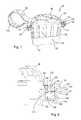
- FIG. 7is a cross-sectional view through the storage device of FIG. 5 in a partially open configuration, before securing means are engaged;
- FIG. 8is a detailed view of the securing means of FIG. 7 ;
- FIG. 9is a cross-sectional view through the storage device of FIG. 5 in a fully closed configuration, with the securing means engaged;
- FIG. 10is a detailed view of the securing means of FIG. 9 ;
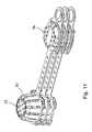
- FIG. 11is a view of three storage devices of FIG. 4 , showing the devices stacked for storage and transportation.
- the storage device of the present inventionis required to have a number of key properties.
- the devicemust be resistant to the cleaning and sterilisation fluids to which it will be exposed, and must be generally tough and durable.
- the storage devicemust protect its contents from damage and as such should be substantially rigid and robust.
- the devicewhile containing the valves or other components, must permit fluids to flow into and out of the device quickly and easily.
- FIGS. 1 and 3A first embodiment of the storage device 20 is illustrated in FIGS. 1 and 3 .
- the storage device 20comprises a tray compartment 1 and a sleeve 5 .
- the tray compartment 1is defined by a substantially rectangular base 2 and surrounding side walls 3 and end walls 4 upstanding therefrom on each side.
- Each wall 3 , 4is, preferably, curved at each end and at the bottom thereof, such that each side wall 3 merges imperceptibly with an adjacent end wall 4 , and with the base 2 .
- the tray compartment 1is required to be large enough to accommodate various flexible medical endoscope valves of different sizes without undue stress being applied to the valves, yet must at the same time be small enough to fit into a standard automated endoscope reprocessing (AER) machine.
- endoscope valvesinclude suction, air/water, biopsy and A/W cleaning valves.
- the side walls 3 along the length of the baseideally have an external length of about 100 mm, whilst the end walls 4 ideally have an external length of about 70 mm.
- the depth of the tray compartment 1is ideally about 50 mm.
- a sleeve 5receives the tray compartment 1 through an open end.
- the sleeve 5may be closed at the other end, or if it is open, then an end of the tray compartment 1 will act to close it.
- the sleeve 5has internal dimensions which correspond to the external dimensions of the tray compartment 1 to ensure a close fit once assembled together.
- the sleeve 5might have an internal length of about 105 mm, an internal width of about 75 mm and an internal depth of about 55 mm, although these dimensions may vary depending on the thickness of the material that the tray compartment is constructed from.
- a strap 13connects the tray compartment 1 to the sleeve 5 , a first end of the strap 13 being attached to a corner of the tray compartment 1 and a second end of the strap 13 being attached to a corner of the sleeve 5 .
- FIG. 2shows an underside view of FIG. 1 , wherein the base of the sleeve 5 has a detachable portion 9 in the form of a tear-off disassembly strip, which can be removed from the sleeve 5 when sufficient force is applied.
- the detachable portion 9is, ideally, defined by a perforated edge and, preferably, has a tab 10 extending from one side to facilitate detachment.
- the underside 6 of the tray compartment 1contains a number of struts 7 which extend across the width of the tray compartment 1 .
- Each strut 7has a number of moulded protrusions 8 provided on it that are arranged to engage with a corresponding number of moulded protrusions 12 provided on a corresponding number of struts 11 on the sleeve 5 when the tray compartment 1 is inserted into the sleeve 5 .
- the protrusions 8 , 12are, preferably, formed as semi-domes and arranged such that, when the tray compartment 1 is inserted into the sleeve 5 , the rounded parts of each semi-dome protrusion 8 , 12 pass over each other.
- the struts 11 on the sleeve 5are arranged on the detachable portion 9 of the sleeve 5 , which allows the tray compartment 1 to be released by removing the detachable portion 9 and hence the struts 11 with the protrusions 12 from the sleeve 5 . Removal of the detachable portion 9 renders the device unusable for a second time because there are no longer any sleeve protrusions 12 for the tray compartment protrusions 8 to interlock with, thus ensuring the single-use nature of the device.
- FIG. 3shows the sleeve 5 with the tray compartment 1 fully inserted and retained therein. Furthermore, it can be seen that the strap 13 is arranged such that when the tray compartment 1 is fully inserted inside the sleeve 5 , the strap 13 can be passed around an endoscope umbilical (light-guide) cable 14 when the tray compartment 1 is being inserted into the sleeve 5 to form a loop that encompasses the endoscope cable 14 so as to ensure that the assembled device remains with the parent endoscope until the detachable portion 9 is detached from the base of the sleeve 5 , preferably by means of applying a sufficient force to the tab 10 .
- endoscope umbilical (light-guide) cable 14when the tray compartment 1 is being inserted into the sleeve 5 to form a loop that encompasses the endoscope cable 14 so as to ensure that the assembled device remains with the parent endoscope until the detachable portion 9 is detached from the base of the sleeve 5 , preferably by means
- the strap 13has to be long enough to enable the valve tray 1 to be inserted into the sleeve 5 and will therefore ideally be about 15 cm long.
- the strap 13has moulded raised projections 15 on both sides to minimise contact between the strap 13 and endoscope cable 14 during a reprocessing procedure.
- Both the tray compartment 1 and the sleeve 5have a plurality of apertures 17 throughout their structures to allow flow of cleaning, disinfection and rinsing solutions during the automated endoscope reprocessing cycle.
- a used endoscopeWhen a used endoscope is to be to be cleaned, by placing it into an automated endoscope reprocessor, for example, its valves are removed from the positions on the endoscope and placed in the tray compartment 1 .
- valveswill have a chain, or similar, attached with a plastic instruction card on it.
- a groove 16is provided in a side wall 3 of the tray compartment 1 that is exposed at an end of the sleeve to allow the chain to pass outside of the tray compartment 1 before it is inserted into the sleeve 5 , to keep any instruction card outside of the tray compartment 1 , where they can be easily accessed.
- the devicewill ensure that the endoscope valves stay with their parent endoscope during reprocessing of the endoscope and subsequent storage until the endoscope is ready to be used again.
- retrieval of the endoscope valvescan be facilitated by removing the detachable portion 9 , thereby allowing the tray compartment 1 to be removed from the sleeve 5 .
- the used tray compartment 1 and sleeve 5are then discarded and new ones used when the endoscope is next reprocessed.
- the present inventionhas been developed particularly for use in keeping valves as a unique set with flexible medical endoscopes and hence is described herein with particular reference to that use. Nevertheless, it will be appreciated that the present invention may also find use in the safe storage of other medical equipment and/or any other situation where it is important that instrument detachable parts be kept together with the parent item using a single-use product.
- the protrusions 8 , 12may be provided along one or both sides of the tray compartment 1 and sleeve 5 , respectively, in which case the detachable portion 9 could be provided on the side(s) of the sleeve 5 to remove the sleeve protrusions 12 .
- the detachable portion 9may not be arranged to remove the protrusions 12 from the sleeve 5 , but could instead be provided on the top of the sleeve 5 , such that its removal will allow the tray compartment 1 to be accessed whilst leaving the securing portions 8 . 12 interlocked, thereby ensuring that the device can only be used once.
- one of the plurality of protrusions 8 , 12could be substituted by a corresponding number of holes, or slots, provided in the respective struts 7 , 11 , whereby the semi-dome protrusions can pass into and out of the holes or slots when the tray compartment 1 is being inserted into the sleeve 5 , but the flat sides of the protrusions will lock against the flat sides of the holes or slots if any attempt is made to retract the tray compartment 1 from the sleeve 5 .
- the plurality of strutscould be arranged in a similar semi-dome fashion the length of the strut, such that the flat sides of corresponding struts 7 , 11 will interlock.
- the protrusionscould also be staggered on corresponding struts 7 , 11 so that there is no interference between protrusions 8 , 12 that are not intended to interlock when the tray compartment 1 is being inserted into the sleeve 5 .
- Another alternative arrangementmight be to substitute the sleeve 5 for a lid, which can be arranged to engage with and close the tray compartment 1 using snap-fit securing components, or similar, that are single-use such that disengagement of the lid would only be possible by disabling the securing components used to secure it to the tray compartment 1 , or by accessing the tray compartment 1 from above using a detachable portion 9 .
- the lidmay be in the shape of an open box, with sides that extend down from the lid sides, such that when the lid is placed over the tray compartment 1 , the sides extend down and over the side walls 3 of the tray compartment 1 .
- the protrusions 8 , 12 , holes/slots, or similar, and detachable portion 9 to remove themcould be provided on the side walls 3 of the tray compartment and lid sides, respectively.
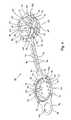
- FIGS. 4 to 11A second preferred embodiment of the present invention is illustrated in FIGS. 4 to 11 .
- a storage device 30comprises a first, container portion 32 and a second, lid portion 34 .
- a connecting portion or strap 36connects the container portion 32 to the lid portion 34 .
- the lid portion 34engages with the container portion 32 to form an enclosure that surrounds one or more pieces of medical equipment placed within the container portion 32 .
- the container portion 32comprises a generally circular base 38 and a side wall 40 that extends from the periphery of the base 38 to a top edge 42 of the container portion 32 , thereby defining an interior space 44 and an opening 46 of the container portion 32 .
- a flange or rim 48extends outwards from the top edge 42 around the complete periphery of the edge 42 .
- an outer edge 50 of the rim 48is generally square-shaped thereby defining four corner regions 52 of the rim 48 .
- Regions of the side wall 40 terminating at the corner regions 52 of the rim 48are of a greater height than regions of the side wall 40 between the corner regions 52 . In this way, the corner regions 52 of the rim 48 are raised compared to side regions 54 of the rim 48 , between the corner regions 52 , and, as such, four dips or recesses 56 are created in the rim 48 between the corner regions 52 .
- a plurality of holes 58are formed in the base 38 of the container portion 32 , and preferably the holes 58 are spaced evenly over the full area of the base 38 .
- the side wall 40comprises a plurality of elongate apertures 60 that extend from proximate the base 38 to proximate the top edge 42 and which are spaced evenly around the side wall 40 .
- the container portion 32further includes partitioning members 62 that extend across the base 38 of the container portion 32 to divide the base 38 into distinct areas.
- the partitioning members 62comprise walls 62 that extend from a central point 64 out to the side wall 40 of the container portion 32 .
- the container portion 32may not include partitioning members, or may include less than or more than four partitioning members.
- the partitioning membersmay be of any suitable form and may divide the base of the container portion into uneven or irregularly sized areas.
- the base 38 of the container portion 32includes a ridge 65 extending from the underside, or exterior, surface of the container portion 32 .
- the device 30may be stood on the ridge 65 so that fluid is still able to drain from the holes 58 in the base 38 .
- the lid portion 34comprises a generally circular central section 66 and a side wall 68 extending around the central section 66 , thereby defining a recessed space 67 in the underside 69 of the lid 34 .
- a rim 70extends outwards from a top edge 72 of the side wall 68 .
- An outer edge 74 of the rim 70is generally square-shaped thereby defining four corner regions 76 of the rim 70 .
- the dimensions of the lid portion 34correspond to the dimensions of the container portion 32 , and in particular the dimensions of the rim 70 are substantially the same as the dimensions of the rim 48 .
- a plurality of holes 78are formed in the central section 66 of the lid portion 34 , and a plurality of elongate apertures 80 are formed in the side wall 68 extending from the central section 66 to the top edge 72 .
- the strap 36is connected at a first end 82 to the rim 48 of the container portion 32 and at a second end 84 to the rim 70 of the lid portion 34 .
- the width of the strap 36is substantially less than a width of the container portion 32 , and in this example, the strap 36 extends from a side region 54 of the rim 48 to a first side region 77 of the rim 70 .
- the strap 36is flexible, and in this embodiment, the thickness of the strap 36 is the same as the thickness of both the rims 48 , 70 , and a first side 86 of the strap 36 is integral or flush with a top surface 88 of the rim 48 and an underside surface 69 of the rim 70 .
- the strap 36comprises a plurality of holes 92 spaced along the length of the strap 36 .
- a plurality of ribs 94extend across the width of the strap 36 on the first side 86 of the strap 36 and each one of the plurality of ribs 94 is located between two holes 92 .
- the ribs 94do not extend across the full width of the strap in this example, but in other embodiments the ribs may extend for the full width of the strap and there may be fewer or more ribs than holes.
- a handle portion or grip portion 96extends from a second side region 77 of the rim 70 , opposite to the first side region 77 .
- the handle portion 96comprises a tab 98 formed from a planar sheet having the same thickness as the rim 70 .
- the tab 98includes a centrally positioned hole 100 , through which a user of the device may place one or more fingers as will be described below.
- the device 30further comprises securing means 122 , the first part 123 of the securing means 122 being located on the container portion 32 and a second part 124 of the securing means 122 being located on the lid portion 34 , as shown most clearly in FIGS. 7-10 .
- the first part 123 of the securing means 122comprises a cavity 126 formed in the rim 48 .
- the cavity 126has an opening 128 in the top surface 88 of the rim 48 , for receiving the second part 124 of the securing means 122 .
- the cavity 126is substantially enclosed, and in particular, a base 130 of the cavity 126 is formed by a part of the undesired surface 132 of the rim 48 .
- the second part 124 of the securing means 122comprises a locking member 134 projecting substantially perpendicularly from the underside surface 90 of the rim 70 .
- the locking member 134comprises a stem portion 136 and a head portion 138 .
- the head portion 138comprises two arms or barbs 140 that extend outwards and rearwards from the distal end 142 of the locking member 134 . In this way, the barbs 140 extend back towards the underside surface 90 on the rim 70 .
- the distance between the ends 144 of the barbs 140is greater than the width of the opening 128 of the first part 123 of the securing means 122 , such that deflection of the barbs 140 is required to insert the locking member 134 into the cavity 126 .
- FIGS. 9 and 10show the storage device 30 in a closed configuration in which the first and second parts 123 , 124 of the securing means 122 are fully engaged.
- the head portion 138 of the locking member 134is fully received within the cavity 126 .
- the ends 144 of the barbs 140are located behind part of the top surface 88 of the rim 48 surrounding the opening 128 . In this way, once the first and second parts 123 , 124 of the securing means 122 have been fully engaged it is not possible to withdraw the locking member 134 from the cavity 126 due to the presence of the barbs 140 .
- the storage device 30comprises four securing means 122 , one of the securing means 122 being located in each corner region 52 , 76 of the rims 48 , 70 .
- the storage device 30may also comprise additional engaging means 146 to aid in the alignment and sealing of the lid portion 34 with the container portion 32 .
- the engaging means 146comprises a recess 148 formed in the rim 48 of the container portion 32 and a protrusion 150 extending from the rim 70 of the lid portion 34 .
- the recess 148 and the protrusion 150are arranged such that the protrusion 150 is received within the recess 148 when the lid portion 34 is aligned with and secured over the container portion 32 .
- the engaging means 146comprises four recesses 148 located adjacent to the cavities 126 in the corner regions 52 of the rim 48 and four protrusions 150 located adjacent to the locking members 134 in each of the four corner regions 76 of the rim 70 .
- this viewshows the device 30 in an open configuration before use.
- a user of the device 30places the required valves or other components (not shown) into the interior space 44 of the container portion 32 .
- the required valves or other componentsmay be placed in the container portion 32 , one in each of the areas bounded by the partitioning walls 62 .
- the device 30is then closed by bending the strap 36 around the parent endoscope and placing the lid 34 over the opening 46 of the container portion 32 , as shown in FIG. 5 .
- the rims 48 , 70are aligned using the engaging means 146 and are pressed together so that the locking members 134 are pushed through the openings 128 .
- the resilient barbs 140 of the head portion 138 of each locking member 134deforms slightly as it is pushed through the respective opening 128 .
- the barbs 140then return to their original shape once through the opening 128 such that the head portion 138 of the locking member 134 is retained within the cavity 126 .
- the top surfaces 88 of the corner regions 52 of the rim 48are in contact with the underside surface 69 of the corner regions 76 of the rim 70 .
- the recesses 56mean that the lower side regions 54 of the rim 48 are not in contact with the respective side regions 77 of the rim 70 and, as such, the recesses 56 form additional openings 57 between the interior space 44 of the container portion 32 and the surroundings.
- valveswill typically have an instruction or record card attached to them by means of a chain or similar.
- the chains or other attachment meansmay be laid within the recess 56 , so that, when the device 30 is closed, the chains or similar pass out of the container portion 32 through the openings 57 so that the instruction or record cards remain on the outside of the device 30 for ease of access at all times.
- the strap 36is wrapped around a portion of the parent endoscope as the device 30 is closed. In this way, the portion of the parent endoscope is contained within a closed loop 152 of the strap 36 .
- the ribs 94 on the strap 36are located on the inner surface of the loop 152 and act to minimise the contact of the strap 36 with the parent endoscope.
- the plurality of holes and apertures 56 , 60 , 78 , 80 both in the container portion 32 and the lid portion 34allow fluid to flow into and out of the interior space 44 of the device 30 .
- the number of holes and apertures 56 , 60 , 78 , 80should not be too great, such that the rigidity and robustness of the container portion 32 and lid portion 34 are affected, thereby compromising the protective nature of the storage device 30 .
- a userWhen a user wishes to remove the valves or components from the container portion 32 , he or she grips the container portion 32 of the device 30 and pulls the handle portion 96 of the lid portion 34 . Preferably the user inserts one or more fingers through the hole 100 in the tab 98 in order to apply sufficient force to pull the lid portion 34 away from the container portion 32 .
- the force the user applies to the lid portion 34breaks the slender stem portions 136 of each of the locking members 134 .
- the lid portion 34can then be pulled away from the container portion 32 , the strap 36 can be unwrapped from the parent endoscope, and the valves or components removed from the container portion 32 .
- the head portions 138 of the locking members 134remain within the cavities 126 when the device 30 is opened.
- FIG. 11shows three storage devices 30 stacked for the purposes of transportation and storage.
- the design of the storage device 30means that the container portions 32 and lid portions 34 of the devices 30 nest together such that each storage device 30 only takes up a minimal amount of space.
- the storage device 30 of the present inventiontherefore, overcomes many of the problems associated with current storage devices.
- the present inventionprovides a single use storage device that allows valves and other components to be kept with a parent endoscope or other piece of medical equipment during storage, cleaning and sterilisation.
Landscapes
- Health & Medical Sciences (AREA)
- Life Sciences & Earth Sciences (AREA)
- Surgery (AREA)
- Animal Behavior & Ethology (AREA)
- General Health & Medical Sciences (AREA)
- Public Health (AREA)
- Veterinary Medicine (AREA)
- Biomedical Technology (AREA)
- Nuclear Medicine, Radiotherapy & Molecular Imaging (AREA)
- Engineering & Computer Science (AREA)
- Heart & Thoracic Surgery (AREA)
- Medical Informatics (AREA)
- Molecular Biology (AREA)
- Epidemiology (AREA)
- Physics & Mathematics (AREA)
- Biophysics (AREA)
- Optics & Photonics (AREA)
- Pathology (AREA)
- Radiology & Medical Imaging (AREA)
- Endoscopes (AREA)
- Instruments For Viewing The Inside Of Hollow Bodies (AREA)
Abstract
Description
- the protection of the endoscope valves before, during and after the processing of the endoscope and valves, either manually or in an automated endoscope reprocessor (AER), against accidental damage or contamination;
- the protection of the staff, patients, and workplace against contamination and possible infection. The risk of contamination deriving from a used and potentially unclean set of endoscope valves due to either the use of non-dedicated cages to store the valves which have a small mesh thus not allowing disinfection solution through, or the use of non-dedicated material bags to store the valves which soak up liquid and can themselves potentially become a biohazard; and
- the protection of unused endoscopes against the potential for cross-contamination from contact with used endoscope valves carrying infectious matter.
- a container portion, for holding one or more pieces of medical equipment;
- a closure portion, designed to engage with the container portion to form an enclosure around said medical equipment;
- a plurality of apertures permitting fluid flow through the storage device; and
- securing means to secure the closure portion to the container portion, the securing means arranged such that once the closure portion has been secured to the container portion using the securing means the closure portion and container portion cannot be separated without permanently disabling the securing means.
Claims (17)
Applications Claiming Priority (5)
| Application Number | Priority Date | Filing Date | Title |
|---|---|---|---|
| GB1018179.0AGB2475948B (en) | 2010-10-27 | 2010-10-27 | Single-use storage device for an endoscope |
| GB1018179.0 | 2010-10-27 | ||
| GB1109522.1 | 2011-06-07 | ||
| GB1109522.1AGB2485011B (en) | 2010-10-27 | 2011-06-07 | Storage device |
| PCT/GB2011/051324WO2012056206A1 (en) | 2010-10-27 | 2011-07-14 | Storage device |
Publications (2)
| Publication Number | Publication Date |
|---|---|
| US20130220855A1 US20130220855A1 (en) | 2013-08-29 |
| US8939287B2true US8939287B2 (en) | 2015-01-27 |
Family
ID=43365629
Family Applications (1)
| Application Number | Title | Priority Date | Filing Date |
|---|---|---|---|
| US13/881,003ActiveUS8939287B2 (en) | 2010-10-27 | 2011-07-14 | Storage device |
Country Status (7)
| Country | Link |
|---|---|
| US (1) | US8939287B2 (en) |
| EP (1) | EP2632497B1 (en) |
| DK (1) | DK2632497T3 (en) |
| ES (1) | ES2625508T3 (en) |
| GB (2) | GB2475948B (en) |
| PT (1) | PT2632497T (en) |
| WO (1) | WO2012056206A1 (en) |
Cited By (25)
| Publication number | Priority date | Publication date | Assignee | Title |
|---|---|---|---|---|
| US20170172345A1 (en)* | 2015-12-22 | 2017-06-22 | Tuesday Morning Partners, Ltd. | Cookware lid with basting projections |
| US20170252118A1 (en)* | 2016-03-04 | 2017-09-07 | Medline Industries, Inc. | Scanner Cover and Corresponding Systems |
| US20170283129A1 (en)* | 2016-03-30 | 2017-10-05 | 9065-3395 Quebec Inc. | Container and lid assembly |
| US20180194516A1 (en)* | 2014-06-19 | 2018-07-12 | Mastronardi Produce Ltd. | Container apparatus |
| US10172669B2 (en) | 2009-10-09 | 2019-01-08 | Ethicon Llc | Surgical instrument comprising an energy trigger lockout |
| US10314638B2 (en) | 2015-04-07 | 2019-06-11 | Ethicon Llc | Articulating radio frequency (RF) tissue seal with articulating state sensing |
| US10603117B2 (en) | 2017-06-28 | 2020-03-31 | Ethicon Llc | Articulation state detection mechanisms |
| US10751117B2 (en) | 2016-09-23 | 2020-08-25 | Ethicon Llc | Electrosurgical instrument with fluid diverter |
| US10751109B2 (en) | 2014-12-22 | 2020-08-25 | Ethicon Llc | High power battery powered RF amplifier topology |
| US10779876B2 (en) | 2011-10-24 | 2020-09-22 | Ethicon Llc | Battery powered surgical instrument |
| US10799284B2 (en) | 2017-03-15 | 2020-10-13 | Ethicon Llc | Electrosurgical instrument with textured jaws |
| US10856934B2 (en) | 2016-04-29 | 2020-12-08 | Ethicon Llc | Electrosurgical instrument with electrically conductive gap setting and tissue engaging members |
| US10959771B2 (en) | 2015-10-16 | 2021-03-30 | Ethicon Llc | Suction and irrigation sealing grasper |
| US10959806B2 (en) | 2015-12-30 | 2021-03-30 | Ethicon Llc | Energized medical device with reusable handle |
| US10987156B2 (en) | 2016-04-29 | 2021-04-27 | Ethicon Llc | Electrosurgical instrument with electrically conductive gap setting member and electrically insulative tissue engaging members |
| US11033323B2 (en) | 2017-09-29 | 2021-06-15 | Cilag Gmbh International | Systems and methods for managing fluid and suction in electrosurgical systems |
| US11033325B2 (en) | 2017-02-16 | 2021-06-15 | Cilag Gmbh International | Electrosurgical instrument with telescoping suction port and debris cleaner |
| US11090103B2 (en) | 2010-05-21 | 2021-08-17 | Cilag Gmbh International | Medical device |
| US11484358B2 (en) | 2017-09-29 | 2022-11-01 | Cilag Gmbh International | Flexible electrosurgical instrument |
| US11490951B2 (en) | 2017-09-29 | 2022-11-08 | Cilag Gmbh International | Saline contact with electrodes |
| US11497546B2 (en) | 2017-03-31 | 2022-11-15 | Cilag Gmbh International | Area ratios of patterned coatings on RF electrodes to reduce sticking |
| US11696811B2 (en) | 2019-12-24 | 2023-07-11 | Boston Scientific Scimed, Inc. | Medical device transportation systems |
| US11883213B2 (en) | 2018-12-26 | 2024-01-30 | Boston Scientific Scimed, Inc. | Medical device containment and transportation systems and methods |
| US11911191B2 (en) | 2019-12-24 | 2024-02-27 | Boston Scientific Scimed, Inc. | Medical device transportation systems |
| US11957342B2 (en) | 2021-11-01 | 2024-04-16 | Cilag Gmbh International | Devices, systems, and methods for detecting tissue and foreign objects during a surgical operation |
Families Citing this family (13)
| Publication number | Priority date | Publication date | Assignee | Title |
|---|---|---|---|---|
| GB2475948B (en)* | 2010-10-27 | 2012-02-08 | Inov8 Medical Solutions Ltd | Single-use storage device for an endoscope |
| GB2485818B (en)* | 2010-11-25 | 2013-03-27 | Medicart Int Ltd | Container for medical accessory processing |
| US20130253256A1 (en)* | 2012-03-20 | 2013-09-26 | David B. Griffith | Apparatuses, systems, and methods for use and transport of magnetic medical devices with transport fixtures or safety cages |
| HUE045989T2 (en)* | 2012-12-14 | 2020-01-28 | Novartis Ag | Container for accommodating an ophthalmic lens during a lens treatment process |
| GB2513643B (en)* | 2013-05-02 | 2017-03-22 | Cantel (Uk) Ltd | Medical accessory holder |
| GB2520714B (en)* | 2013-11-28 | 2016-03-16 | Keymed Medicals & Ind Equip | An endoscope valve container |
| AU2014100602A4 (en)* | 2014-05-20 | 2014-07-10 | Multisteps Pty Ltd | A Produce Container |
| US11478320B2 (en)* | 2015-08-06 | 2022-10-25 | Jacobs Emerging Technologies, Llc | Medical device holder |
| MY190676A (en) | 2015-09-25 | 2022-05-10 | Novartis Ag | Container for accommodating an ophthalmic lens during a lens treatment process |
| CA3006694A1 (en) | 2015-12-24 | 2017-06-29 | Cantel (Uk) Limited | Medical accessory holder |
| NL2017723B1 (en) | 2016-11-04 | 2018-05-23 | Wassenburg Medical B V | Tip protector device |
| CN110366488B (en)* | 2017-04-03 | 2021-06-22 | 爱尔康公司 | Carrier for carrying ophthalmic lenses during treatment thereof in a bath |
| US20210371150A1 (en)* | 2020-05-29 | 2021-12-02 | Alcon Inc. | Carrier for carrying an ophthalmic lens during its treatment in a bath |
Citations (37)
| Publication number | Priority date | Publication date | Assignee | Title |
|---|---|---|---|---|
| US3485416A (en)* | 1967-12-01 | 1969-12-23 | Seymour F Fohrman | Combination salt and pepper shaker |
| US4331257A (en) | 1980-12-18 | 1982-05-25 | Aesculap-Werke Aktiengesellschaft Vormals Jetter & Scheerer | Closure for a container having additional securing means |
| US4418819A (en)* | 1982-09-30 | 1983-12-06 | Shapiro Richard N | Dual container apparatus |
| US4658955A (en)* | 1984-05-26 | 1987-04-21 | Eichner Organisation Kg | Mailer for recording media |
| US4782977A (en)* | 1987-12-16 | 1988-11-08 | Evergreen Industries, Inc. | Tamper resistant container |
| US5031768A (en) | 1990-04-09 | 1991-07-16 | Ultradent Products, Inc. | Instrument tray and disposable receptacle having alternative locking means |
| US5044512A (en)* | 1990-12-12 | 1991-09-03 | Giancaspro Joseph C | Bottle apparatus |
| US5096114A (en) | 1990-03-30 | 1992-03-17 | Corrugated Container Corporation | Disposable container for hazardous waste products |
| GB2261359A (en) | 1991-08-22 | 1993-05-19 | Paul Bone | Container suitable for disposal of hospital waste |
| US5235795A (en) | 1990-05-09 | 1993-08-17 | Deroyal Industries, Inc. | System for the delivery, storage and disposal of medical supplies |
| US5285918A (en)* | 1992-12-10 | 1994-02-15 | Alpha Enterprises, Inc. | Videocassette shipping container |
| US5294413A (en)* | 1991-07-17 | 1994-03-15 | Hu-Friedy Mfg. Co., Inc. | Sterilization and storage cassette |
| US5312011A (en)* | 1992-08-13 | 1994-05-17 | Ultradent Products, Inc. | Stackable container system |
| US5465901A (en)* | 1994-12-01 | 1995-11-14 | Paine, Jr.; Derrick | Basket for produce |
| US5482067A (en) | 1995-02-15 | 1996-01-09 | Wittrock; Paul | Instrument cleaning cassette with guided double hinge |
| US5588853A (en)* | 1995-05-17 | 1996-12-31 | Hubbell Incorporated | Closure cap with gasket for electrical connector housing |
| US5979690A (en)* | 1997-11-19 | 1999-11-09 | Berry Plastic Corporation | Reclosable rectangular container assembly with tamper indicator |
| US6227399B1 (en)* | 1999-11-23 | 2001-05-08 | Bunzl Plastics Inc. | Tamper-evident fastening assembly |
| US20020162838A1 (en)* | 2001-05-01 | 2002-11-07 | Leaphart C. Mark | Sock washing device |
| US20030052133A1 (en)* | 2001-09-14 | 2003-03-20 | Hayes Thomas J. | Containers |
| US20030080571A1 (en) | 2000-03-23 | 2003-05-01 | Medin Corporation | Tamper-proof seal and method for using same |
| US20030198714A1 (en)* | 1996-01-24 | 2003-10-23 | Anthony Cadiente | Method and apparatus for packing and bi-directional cooling of produce |
| US6699331B1 (en)* | 1998-08-20 | 2004-03-02 | Novapharm Research (Australia) Pty Ltd | Endoscope cleaning device |
| US20040112896A1 (en)* | 2002-12-11 | 2004-06-17 | Christopher Lewis | Container with rotating hinged lid |
| WO2005053597A2 (en) | 2003-11-26 | 2005-06-16 | Hu-Friedy Mfg. Co., Inc. | Configurable cassettes |
| US20060076309A1 (en)* | 2004-10-12 | 2006-04-13 | Joel Delman | Mother's milk container closure and attachment assembly |
| US20060266666A1 (en) | 2005-05-24 | 2006-11-30 | Bettenhausen Todd E | Modular container for the storage, organization, protection, sterilization and delivery of medical instruments and implants |
| US20060289549A1 (en)* | 2005-06-24 | 2006-12-28 | Terry Vovan | Edge-tearing tamper-evident container |
| US20070045317A1 (en)* | 2005-08-31 | 2007-03-01 | Rosender Adam K | Tamper evident thermoformed containers |
| US20070138180A1 (en)* | 2005-12-21 | 2007-06-21 | Terry Vovan | Enhanced tamper evident bowl with blocked tab |
| US20070212277A1 (en)* | 2006-03-07 | 2007-09-13 | Riley Edward D | Medical instrument container system |
| US20070272688A1 (en)* | 2003-10-22 | 2007-11-29 | Eugenio Longo | Reclosable Rigid Container Assembly |
| US20080116095A1 (en)* | 2006-03-07 | 2008-05-22 | Riley Edward D | Medical Instrument Container System |
| US20100127010A1 (en)* | 2008-11-25 | 2010-05-27 | Philip Raymond Short | Nestable produce container |
| US20100158751A1 (en) | 2008-12-24 | 2010-06-24 | Steven Scott Friderich | Single use sterilization container |
| DE202010005089U1 (en) | 2010-04-15 | 2010-07-01 | Nopa Instruments Medizintechnik Gmbh | Sterile containers for medical purposes |
| GB2475948A (en) | 2010-10-27 | 2011-06-08 | Inov8 Medical Solutions Ltd | Single use device for storing endoscope valves |
Family Cites Families (2)
| Publication number | Priority date | Publication date | Assignee | Title |
|---|---|---|---|---|
| US8623289B2 (en)* | 2008-12-24 | 2014-01-07 | Kimberly-Clark Worldwide Inc. | Single use sterilization container |
| GB2485818B (en)* | 2010-11-25 | 2013-03-27 | Medicart Int Ltd | Container for medical accessory processing |
- 2010
- 2010-10-27GBGB1018179.0Apatent/GB2475948B/enactiveActive
- 2011
- 2011-06-07GBGB1109522.1Apatent/GB2485011B/enactiveActive
- 2011-07-14WOPCT/GB2011/051324patent/WO2012056206A1/enactiveApplication Filing
- 2011-07-14EPEP11749883.2Apatent/EP2632497B1/enactiveActive
- 2011-07-14ESES11749883.2Tpatent/ES2625508T3/enactiveActive
- 2011-07-14DKDK11749883.2Tpatent/DK2632497T3/enactive
- 2011-07-14PTPT117498832Tpatent/PT2632497T/enunknown
- 2011-07-14USUS13/881,003patent/US8939287B2/enactiveActive
Patent Citations (45)
| Publication number | Priority date | Publication date | Assignee | Title |
|---|---|---|---|---|
| US3485416A (en)* | 1967-12-01 | 1969-12-23 | Seymour F Fohrman | Combination salt and pepper shaker |
| US4331257A (en) | 1980-12-18 | 1982-05-25 | Aesculap-Werke Aktiengesellschaft Vormals Jetter & Scheerer | Closure for a container having additional securing means |
| US4418819A (en)* | 1982-09-30 | 1983-12-06 | Shapiro Richard N | Dual container apparatus |
| US4658955A (en)* | 1984-05-26 | 1987-04-21 | Eichner Organisation Kg | Mailer for recording media |
| US4782977A (en)* | 1987-12-16 | 1988-11-08 | Evergreen Industries, Inc. | Tamper resistant container |
| US5096114A (en) | 1990-03-30 | 1992-03-17 | Corrugated Container Corporation | Disposable container for hazardous waste products |
| US5031768A (en) | 1990-04-09 | 1991-07-16 | Ultradent Products, Inc. | Instrument tray and disposable receptacle having alternative locking means |
| US5235795A (en) | 1990-05-09 | 1993-08-17 | Deroyal Industries, Inc. | System for the delivery, storage and disposal of medical supplies |
| US5044512A (en)* | 1990-12-12 | 1991-09-03 | Giancaspro Joseph C | Bottle apparatus |
| US5294413A (en)* | 1991-07-17 | 1994-03-15 | Hu-Friedy Mfg. Co., Inc. | Sterilization and storage cassette |
| GB2261359A (en) | 1991-08-22 | 1993-05-19 | Paul Bone | Container suitable for disposal of hospital waste |
| US5312011A (en)* | 1992-08-13 | 1994-05-17 | Ultradent Products, Inc. | Stackable container system |
| US5285918A (en)* | 1992-12-10 | 1994-02-15 | Alpha Enterprises, Inc. | Videocassette shipping container |
| US5465901A (en)* | 1994-12-01 | 1995-11-14 | Paine, Jr.; Derrick | Basket for produce |
| US5482067A (en) | 1995-02-15 | 1996-01-09 | Wittrock; Paul | Instrument cleaning cassette with guided double hinge |
| US5588853A (en)* | 1995-05-17 | 1996-12-31 | Hubbell Incorporated | Closure cap with gasket for electrical connector housing |
| US7100788B2 (en)* | 1996-01-24 | 2006-09-05 | Sambrailo Packaging, Inc. | Method and apparatus for packing and bi-directional cooling of produce |
| US20030198714A1 (en)* | 1996-01-24 | 2003-10-23 | Anthony Cadiente | Method and apparatus for packing and bi-directional cooling of produce |
| US5979690A (en)* | 1997-11-19 | 1999-11-09 | Berry Plastic Corporation | Reclosable rectangular container assembly with tamper indicator |
| US6699331B1 (en)* | 1998-08-20 | 2004-03-02 | Novapharm Research (Australia) Pty Ltd | Endoscope cleaning device |
| US6227399B1 (en)* | 1999-11-23 | 2001-05-08 | Bunzl Plastics Inc. | Tamper-evident fastening assembly |
| US20030080571A1 (en) | 2000-03-23 | 2003-05-01 | Medin Corporation | Tamper-proof seal and method for using same |
| US20050139599A1 (en) | 2000-03-23 | 2005-06-30 | Medin Corporation | Tamper-proof seal and method for using same |
| US20020162838A1 (en)* | 2001-05-01 | 2002-11-07 | Leaphart C. Mark | Sock washing device |
| US20030052133A1 (en)* | 2001-09-14 | 2003-03-20 | Hayes Thomas J. | Containers |
| US6845878B2 (en)* | 2001-09-14 | 2005-01-25 | Pactiv Corporation | Containers |
| WO2004018305A2 (en) | 2002-08-23 | 2004-03-04 | Medin Corporation | Tamper-proof seal and method for using same |
| US20040112896A1 (en)* | 2002-12-11 | 2004-06-17 | Christopher Lewis | Container with rotating hinged lid |
| US20070272688A1 (en)* | 2003-10-22 | 2007-11-29 | Eugenio Longo | Reclosable Rigid Container Assembly |
| WO2005053597A2 (en) | 2003-11-26 | 2005-06-16 | Hu-Friedy Mfg. Co., Inc. | Configurable cassettes |
| US20050161355A1 (en) | 2003-11-26 | 2005-07-28 | Hu-Friedy Mfg. Co., Inc. | Configurable cassettes |
| US20060076309A1 (en)* | 2004-10-12 | 2006-04-13 | Joel Delman | Mother's milk container closure and attachment assembly |
| US20070144926A1 (en) | 2005-05-24 | 2007-06-28 | Bettenhausen Todd E | Modular container for the storage, organization, protection, sterilization and delivery of medical instruments and implants |
| US20060266666A1 (en) | 2005-05-24 | 2006-11-30 | Bettenhausen Todd E | Modular container for the storage, organization, protection, sterilization and delivery of medical instruments and implants |
| WO2006127230A2 (en) | 2005-05-24 | 2006-11-30 | Containmed, Inc. | Container for medical instruments and implants |
| US20060289549A1 (en)* | 2005-06-24 | 2006-12-28 | Terry Vovan | Edge-tearing tamper-evident container |
| US20070045317A1 (en)* | 2005-08-31 | 2007-03-01 | Rosender Adam K | Tamper evident thermoformed containers |
| US20070138180A1 (en)* | 2005-12-21 | 2007-06-21 | Terry Vovan | Enhanced tamper evident bowl with blocked tab |
| US20070212277A1 (en)* | 2006-03-07 | 2007-09-13 | Riley Edward D | Medical instrument container system |
| US20080116095A1 (en)* | 2006-03-07 | 2008-05-22 | Riley Edward D | Medical Instrument Container System |
| US20100127010A1 (en)* | 2008-11-25 | 2010-05-27 | Philip Raymond Short | Nestable produce container |
| US8328039B2 (en)* | 2008-11-25 | 2012-12-11 | Vortex Packaging Niagara, Inc. | Nestable produce container |
| US20100158751A1 (en) | 2008-12-24 | 2010-06-24 | Steven Scott Friderich | Single use sterilization container |
| DE202010005089U1 (en) | 2010-04-15 | 2010-07-01 | Nopa Instruments Medizintechnik Gmbh | Sterile containers for medical purposes |
| GB2475948A (en) | 2010-10-27 | 2011-06-08 | Inov8 Medical Solutions Ltd | Single use device for storing endoscope valves |
Non-Patent Citations (8)
| Title |
|---|
| Abstracts from ESGENA Conference 2007, 11th Meeting of the European Society of Gastroenterology and Endoscopy Nurses and Associates, Oct. 27-29, 2007, 53 pages. |
| Decontamination of Endoscopes, Medical Devices Agency, MDA DB2002(05), Jul. 2002, 55 pages. |
| GB Search Report bearing a mailing date of Jan. 19, 2011, 1 page. |
| GB Search Report bearing a mailing date of Sep. 26, 2011, 1 page. |
| NHS Decontamination Standards for Flexible Endoscopes, National Endoscopy Programme, www.grs.nhs.uk, Mar. 2008, 14 pages. |
| Partners for Endoscopy, www.plemedical.co.uk, Feb. 2009, 3 pages. |
| Ruhof Endo-Bag Data Sheet and Article, www.rahol.co.uk. Sep. 15, 2011, 2 pages. |
| The Report of an Independent Review of Endoscope Decontamination in Northern Ireland, Departement of Health, Ref: 296/2004, Mar. 2005, 52 pages. |
Cited By (35)
| Publication number | Priority date | Publication date | Assignee | Title |
|---|---|---|---|---|
| US10172669B2 (en) | 2009-10-09 | 2019-01-08 | Ethicon Llc | Surgical instrument comprising an energy trigger lockout |
| US11090103B2 (en) | 2010-05-21 | 2021-08-17 | Cilag Gmbh International | Medical device |
| US10779876B2 (en) | 2011-10-24 | 2020-09-22 | Ethicon Llc | Battery powered surgical instrument |
| US10611517B2 (en)* | 2014-06-19 | 2020-04-07 | Mastronardi Produce Ltd. | Ventilated container apparatus |
| US11345510B2 (en) | 2014-06-19 | 2022-05-31 | Mastronardi Produce Ltd. | Ventilated container apparatus |
| US20180194516A1 (en)* | 2014-06-19 | 2018-07-12 | Mastronardi Produce Ltd. | Container apparatus |
| US10751109B2 (en) | 2014-12-22 | 2020-08-25 | Ethicon Llc | High power battery powered RF amplifier topology |
| US10314638B2 (en) | 2015-04-07 | 2019-06-11 | Ethicon Llc | Articulating radio frequency (RF) tissue seal with articulating state sensing |
| US10959771B2 (en) | 2015-10-16 | 2021-03-30 | Ethicon Llc | Suction and irrigation sealing grasper |
| US10264921B2 (en)* | 2015-12-22 | 2019-04-23 | Tuesday Morning Partners, Ltd. | Cookware lid with basting projections |
| US20170172345A1 (en)* | 2015-12-22 | 2017-06-22 | Tuesday Morning Partners, Ltd. | Cookware lid with basting projections |
| US11382459B2 (en) | 2015-12-22 | 2022-07-12 | Tuesday Morning Partners, Ltd. | Cookware lid with basting projections |
| US10959806B2 (en) | 2015-12-30 | 2021-03-30 | Ethicon Llc | Energized medical device with reusable handle |
| US11759278B2 (en) | 2016-03-04 | 2023-09-19 | Medline Industries, Lp | Scanner cover and corresponding systems |
| US20170252118A1 (en)* | 2016-03-04 | 2017-09-07 | Medline Industries, Inc. | Scanner Cover and Corresponding Systems |
| US10172681B2 (en)* | 2016-03-04 | 2019-01-08 | Medline Industries, Inc. | Scanner cover and corresponding systems |
| US20170283129A1 (en)* | 2016-03-30 | 2017-10-05 | 9065-3395 Quebec Inc. | Container and lid assembly |
| US10856934B2 (en) | 2016-04-29 | 2020-12-08 | Ethicon Llc | Electrosurgical instrument with electrically conductive gap setting and tissue engaging members |
| US10987156B2 (en) | 2016-04-29 | 2021-04-27 | Ethicon Llc | Electrosurgical instrument with electrically conductive gap setting member and electrically insulative tissue engaging members |
| US12295644B2 (en) | 2016-09-23 | 2025-05-13 | Cilag Gmbh International | Electrosurgical instrument with fluid diverter |
| US10751117B2 (en) | 2016-09-23 | 2020-08-25 | Ethicon Llc | Electrosurgical instrument with fluid diverter |
| US11839422B2 (en) | 2016-09-23 | 2023-12-12 | Cilag Gmbh International | Electrosurgical instrument with fluid diverter |
| US11033325B2 (en) | 2017-02-16 | 2021-06-15 | Cilag Gmbh International | Electrosurgical instrument with telescoping suction port and debris cleaner |
| US10799284B2 (en) | 2017-03-15 | 2020-10-13 | Ethicon Llc | Electrosurgical instrument with textured jaws |
| US12023087B2 (en) | 2017-03-15 | 2024-07-02 | Cilag Gmbh International | Electrosurgical instrument with textured jaws |
| US11497546B2 (en) | 2017-03-31 | 2022-11-15 | Cilag Gmbh International | Area ratios of patterned coatings on RF electrodes to reduce sticking |
| US10603117B2 (en) | 2017-06-28 | 2020-03-31 | Ethicon Llc | Articulation state detection mechanisms |
| US11490951B2 (en) | 2017-09-29 | 2022-11-08 | Cilag Gmbh International | Saline contact with electrodes |
| US11484358B2 (en) | 2017-09-29 | 2022-11-01 | Cilag Gmbh International | Flexible electrosurgical instrument |
| US11033323B2 (en) | 2017-09-29 | 2021-06-15 | Cilag Gmbh International | Systems and methods for managing fluid and suction in electrosurgical systems |
| US12390264B2 (en) | 2017-09-29 | 2025-08-19 | Cilag Gmbh International | Systems and methods for managing fluid and suction in electrosurgical systems |
| US11883213B2 (en) | 2018-12-26 | 2024-01-30 | Boston Scientific Scimed, Inc. | Medical device containment and transportation systems and methods |
| US11696811B2 (en) | 2019-12-24 | 2023-07-11 | Boston Scientific Scimed, Inc. | Medical device transportation systems |
| US11911191B2 (en) | 2019-12-24 | 2024-02-27 | Boston Scientific Scimed, Inc. | Medical device transportation systems |
| US11957342B2 (en) | 2021-11-01 | 2024-04-16 | Cilag Gmbh International | Devices, systems, and methods for detecting tissue and foreign objects during a surgical operation |
Also Published As
| Publication number | Publication date |
|---|---|
| US20130220855A1 (en) | 2013-08-29 |
| WO2012056206A1 (en) | 2012-05-03 |
| GB201018179D0 (en) | 2010-12-08 |
| AU2011322288A1 (en) | 2013-06-13 |
| GB2485011A (en) | 2012-05-02 |
| GB2485011B (en) | 2017-06-28 |
| DK2632497T3 (en) | 2017-06-06 |
| ES2625508T3 (en) | 2017-07-19 |
| PT2632497T (en) | 2017-05-18 |
| EP2632497A1 (en) | 2013-09-04 |
| EP2632497B1 (en) | 2017-03-15 |
| GB2475948B (en) | 2012-02-08 |
| GB201109522D0 (en) | 2011-07-20 |
| GB2475948A (en) | 2011-06-08 |
Similar Documents
| Publication | Publication Date | Title |
|---|---|---|
| US8939287B2 (en) | Storage device | |
| US10405938B2 (en) | Storage kit and assembly | |
| RU2649526C2 (en) | Storage device | |
| US10668176B2 (en) | Sterilization tray | |
| US20050082188A1 (en) | Surgical or medical instrument holder | |
| US8501109B2 (en) | Disinfection system | |
| AU2011322288B2 (en) | Storage device | |
| RU2664949C2 (en) | Transportation of medical instruments | |
| HK1230549A1 (en) | Transportation of medical instruments | |
| HK1230549B (en) | Transportation of medical instruments |
Legal Events
| Date | Code | Title | Description |
|---|---|---|---|
| AS | Assignment | Owner name:INOV8 MEDICAL SOLUTIONS LIMITED, UNITED KINGDOM Free format text:ASSIGNMENT OF ASSIGNORS INTEREST;ASSIGNOR:MARKOVITCH, DANIEL ANDREW;REEL/FRAME:030435/0833 Effective date:20130429 | |
| STCF | Information on status: patent grant | Free format text:PATENTED CASE | |
| AS | Assignment | Owner name:MEDICAL INNOVATIONS LIMITED, UNITED KINGDOM Free format text:ASSIGNMENT OF ASSIGNORS INTEREST;ASSIGNOR:INOV8 MEDICAL SOLUTIONS LIMITED;REEL/FRAME:035369/0135 Effective date:20150304 | |
| FEPP | Fee payment procedure | Free format text:PAT HOLDER NO LONGER CLAIMS SMALL ENTITY STATUS, ENTITY STATUS SET TO UNDISCOUNTED (ORIGINAL EVENT CODE: STOL); ENTITY STATUS OF PATENT OWNER: LARGE ENTITY | |
| AS | Assignment | Owner name:CANTEL (UK) LIMITED, UNITED KINGDOM Free format text:CHANGE OF NAME;ASSIGNOR:MEDICAL INNOVATIONS LIMITED;REEL/FRAME:038706/0535 Effective date:20160503 | |
| MAFP | Maintenance fee payment | Free format text:PAYMENT OF MAINTENANCE FEE, 4TH YEAR, LARGE ENTITY (ORIGINAL EVENT CODE: M1551) Year of fee payment:4 | |
| MAFP | Maintenance fee payment | Free format text:PAYMENT OF MAINTENANCE FEE, 8TH YEAR, LARGE ENTITY (ORIGINAL EVENT CODE: M1552); ENTITY STATUS OF PATENT OWNER: LARGE ENTITY Year of fee payment:8 | |
| AS | Assignment | Owner name:STERIS SOLUTIONS LIMITED, UNITED KINGDOM Free format text:ASSIGNMENT OF ASSIGNORS INTEREST;ASSIGNOR:CANTEL (UK) LIMITED;REEL/FRAME:065516/0525 Effective date:20231020 |