US8938753B2 - Configurable computer system - Google Patents
Configurable computer systemDownload PDFInfo
- Publication number
- US8938753B2 US8938753B2US12/910,333US91033310AUS8938753B2US 8938753 B2US8938753 B2US 8938753B2US 91033310 AUS91033310 AUS 91033310AUS 8938753 B2US8938753 B2US 8938753B2
- Authority
- US
- United States
- Prior art keywords
- base station
- remote control
- user interface
- content
- mode
- Prior art date
- Legal status (The legal status is an assumption and is not a legal conclusion. Google has not performed a legal analysis and makes no representation as to the accuracy of the status listed.)
- Active, expires
Links
Images


Classifications
- H—ELECTRICITY
- H04—ELECTRIC COMMUNICATION TECHNIQUE
- H04N—PICTORIAL COMMUNICATION, e.g. TELEVISION
- H04N21/00—Selective content distribution, e.g. interactive television or video on demand [VOD]
- H04N21/40—Client devices specifically adapted for the reception of or interaction with content, e.g. set-top-box [STB]; Operations thereof
- H04N21/41—Structure of client; Structure of client peripherals
- H04N21/414—Specialised client platforms, e.g. receiver in car or embedded in a mobile appliance
- H04N21/4143—Specialised client platforms, e.g. receiver in car or embedded in a mobile appliance embedded in a Personal Computer [PC]
- H—ELECTRICITY
- H04—ELECTRIC COMMUNICATION TECHNIQUE
- H04N—PICTORIAL COMMUNICATION, e.g. TELEVISION
- H04N21/00—Selective content distribution, e.g. interactive television or video on demand [VOD]
- H04N21/40—Client devices specifically adapted for the reception of or interaction with content, e.g. set-top-box [STB]; Operations thereof
- H04N21/41—Structure of client; Structure of client peripherals
- H04N21/422—Input-only peripherals, i.e. input devices connected to specially adapted client devices, e.g. global positioning system [GPS]
- H04N21/42204—User interfaces specially adapted for controlling a client device through a remote control device; Remote control devices therefor
- H04N21/42206—User interfaces specially adapted for controlling a client device through a remote control device; Remote control devices therefor characterized by hardware details
- H04N21/4221—Dedicated function buttons, e.g. for the control of an EPG, subtitles, aspect ratio, picture-in-picture or teletext
- H—ELECTRICITY
- H04—ELECTRIC COMMUNICATION TECHNIQUE
- H04N—PICTORIAL COMMUNICATION, e.g. TELEVISION
- H04N21/00—Selective content distribution, e.g. interactive television or video on demand [VOD]
- H04N21/40—Client devices specifically adapted for the reception of or interaction with content, e.g. set-top-box [STB]; Operations thereof
- H04N21/47—End-user applications
- H04N21/478—Supplemental services, e.g. displaying phone caller identification, shopping application
- H—ELECTRICITY
- H04—ELECTRIC COMMUNICATION TECHNIQUE
- H04N—PICTORIAL COMMUNICATION, e.g. TELEVISION
- H04N21/00—Selective content distribution, e.g. interactive television or video on demand [VOD]
- H04N21/40—Client devices specifically adapted for the reception of or interaction with content, e.g. set-top-box [STB]; Operations thereof
- H04N21/41—Structure of client; Structure of client peripherals
- H04N21/422—Input-only peripherals, i.e. input devices connected to specially adapted client devices, e.g. global positioning system [GPS]
- H04N21/42204—User interfaces specially adapted for controlling a client device through a remote control device; Remote control devices therefor
- H04N21/42206—User interfaces specially adapted for controlling a client device through a remote control device; Remote control devices therefor characterized by hardware details
- H04N21/42212—Specific keyboard arrangements
- H04N21/42213—Specific keyboard arrangements for facilitating data entry
- H04N21/42214—Specific keyboard arrangements for facilitating data entry using alphanumerical characters
- H—ELECTRICITY
- H04—ELECTRIC COMMUNICATION TECHNIQUE
- H04N—PICTORIAL COMMUNICATION, e.g. TELEVISION
- H04N21/00—Selective content distribution, e.g. interactive television or video on demand [VOD]
- H04N21/40—Client devices specifically adapted for the reception of or interaction with content, e.g. set-top-box [STB]; Operations thereof
- H04N21/41—Structure of client; Structure of client peripherals
- H04N21/422—Input-only peripherals, i.e. input devices connected to specially adapted client devices, e.g. global positioning system [GPS]
- H04N21/42204—User interfaces specially adapted for controlling a client device through a remote control device; Remote control devices therefor
- H04N21/42206—User interfaces specially adapted for controlling a client device through a remote control device; Remote control devices therefor characterized by hardware details
- H04N21/42224—Touch pad or touch panel provided on the remote control
Definitions
- aspects of the present inventionrelate generally to computer systems that are connected to a television and used for viewing television signal information and Internet information.
- common integrated media outletsmay include mobile television (e.g., access to a television broadcast signal through a mobile device such as a mobile phone) and mobile Internet (e.g., access to the Internet through a mobile device such as a mobile phone).
- mobile televisione.g., access to a television broadcast signal through a mobile device such as a mobile phone
- mobile Internete.g., access to the Internet through a mobile device such as a mobile phone
- an external displaye.g., a television, LCD or projector
- an external displaye.g., a television, LCD or projector
- S-VideoSeparate Video
- HDMIHigh Definition Multimedia Interface
- aspects in accord with the present inventionare directed to computer systems that are connected to an external display device, such as a television, and used for viewing television signal information and Internet information.
- an external display devicesuch as a television
- a computer systemis connected to an external display device, such as a television
- an external display devicesuch as a television
- certain compatibility problemsmay arise.
- the external display deviceis configured to display one type of signal (e.g., television broadcast signals) and is not configured to display output display signals from the computer system.
- the signals sent by the computer systemare configured to be displayed on a computer screen or monitor viewed from a relatively short distance from the screen and not on an external display device viewed from a greater distance.
- an additional problem with connecting a computer system to an external display device, such as a televisionis that the controls of the computer system may not be configured adequately to interact efficiently with the display shown on the external display device.
- the present inventionprovides a computer system capable of being coupled to an external display device, such as a television, that provides efficient control of the computer system through the external display device, and reduces problems with external display device/computer system compatibility, as discussed above.
- an external display devicesuch as a television
- the present inventionfeatures a method of optimizing output display signals from a computer system.
- the methodmay comprise acts of providing an interface in the computer system adapted to be connected to an external display device, and providing a controller in the computer system adapted to transmit output display signals to the external display device, wherein the output display signals are configured to generate a user interface displayed on the external display device, receive, from the external display device, external display device identification information, determine, in response to receiving the external display device identification information, whether the external display device was previously connected to the computer system, and in response to determining that the external display device was previously connected to the computer system, automatically configure a layout of the user interface to display within a previously defined display area of the external display device and automatically compensate the layout of the user interface for a previously defined overscan region of the external display device.
- the controlleris further adapted to automatically initiate, in response to determining that the external display device was not previously connected to the computer system, an overscan wizard displayed on the external display device, and permit a user, upon initiating the overscan wizard, to define an appropriate boundary of the display area of the external display device.
- the controlleris further adapted to automatically adjust, in response to the user defining the appropriate boundaries of the display area, a layout of the user interface to fit entirely within the appropriate boundary of the display area of the external display device.
- the controlleris further adapted to receive display capability information related to the external display device, and automatically configure the layout of the user interface in response to receiving the display capability information.
- the controlleris further adapted to automatically configure the user interface to display within a zoomed in display area of the external display device.
- the controlleris further adapted to automatically enlarge a cursor configured to be displayed within the display area of the external display device.
- the present inventionfeatures a computer system.
- the computer systemmay comprise a base station configured to be coupled to an external network and to communicate with the external network, an external display device coupled to the base station and configured to receive output display signals from the base station, and a user interface displayed on the external display device and generated in response to the output display signals from the base station, wherein the base station is configured to receive an external display device identification signal from the external display device, determine whether the base station has been coupled to the external display device before, and in response to a determination that the base station has not been coupled to the external display device before, automatically initiating an overscan wizard displayed on the external display device to permit a user to define an acceptable display boundary of the external display device.
- the base stationin response to a determination that the base station has been coupled to the external display device before, the base station automatically configures the user interface to display within a pre-defined display boundary associated with the previously connected external display device.
- the user interfaceincludes zoomed in information.
- the external display deviceis a television.
- the base stationis configured to be coupled to the television via an HDMI connection.
- the user interfaceincludes an enlarged cursor, operable by a user to interact with the user interface.
- the user interfaceincludes header information, wherein the header information is configured to be hidden when not selected by the cursor.
- the user interfaceincludes at least one system information message, wherein in response to the at least one system information message being displayed, the cursor is configured to automatically focus on the system message.
- the user interfaceincludes an enlarged first text field and a second text field, wherein the enlarged first text field is configured to mirror the second text field and to be displayed when a user enters text into the second text field.
- the present inventionfeatures a computer system.
- the computer systemmay comprise a base station configured to be coupled to an external network and to communicate with the external network, an external display device coupled to the base station and configured to receive output display signals from the base station, a user interface displayed on the external display device and generated in response to the output display signals from the base station, and a means for optimizing the user interface to be adequately displayed on the external display device.
- the means for optimizingincludes a means for automatically configuring the user interface based on display capability information sent from the external display device to the base station.
- the means for optimizingincludes a means for determining an overscan region of the external display device and in response, compensating the external display device.
- the computer systemfurther comprises a means for determining that the external display device has previously been coupled to the base station and a means for automatically configuring the user interface based on display capability information of the previously connected external display device.
- the present inventionfeatures a non-transitory computer-readable medium comprising computer-executable instructions that, when executed on a processor, perform a method for optimizing output display signals from a computer system, the method comprising acts of providing an interface in the computer system adapted to be connected to an external display device, and providing a controller in the computer system adapted to transmit output display signals to the external display device, wherein the output display signals are configured to generate a user interface displayed on the external display device, receive, from the external display device, external display device identification information, determine, in response to receiving the external display device identification information, whether the external display device was previously connected to the computer system, and in response to determining that the external display device was previously connected to the computer system, automatically configure a layout of the user interface to display within a previously defined display area of the external display device and automatically compensate the layout of the user interface for a previously defined overscan region of the external display device.
- the present inventionfeatures a remote control for operating a computer system.
- the remote controlmay comprise a housing comprising a first housing portion and a second housing portion, wherein the first housing portion is coupled to the second housing portion and is configurable in at least two positions in relation to the second housing portion, a touchpad coupled to the first housing portion, a keypad coupled to the second housing portion, a processor located within the housing and operatively coupled to both the touchpad and the keypad, the processor being configured to receive control signals from the touch pad and the keypad, and an RF transmitter coupled to the processor and configured to transmit signals from the processor to the computer system, wherein, in a first configuration of the remote control, the first housing portion is configured to be manipulated to a first position in relation to the second housing portion and the remote control is configured to operate in a first mode of operation, and wherein, in a second configuration of the remote control, the first housing portion is configured to be manipulated to a second position in relation to the second housing portion, and wherein the remote control is configured to operate in a second
- the first housing portionis slideably coupled to the second housing portion, wherein, in the first configuration, the first housing portion is configured to be slid to the first position in relation to the second housing portion, and wherein, in the second configuration, the first housing portion is configured to be slid to the second position in relation to the second housing portion.
- the first housing portionis configured to be slid to the first position so as to limit access to the keypad.
- the first housing portionis configured to be slid to the second position so as to provide access to the keypad and the touchpad.
- the touchpadis configured to provide a first set of control signals to the processor in response to the remote control being operated in the first mode of operation, and wherein the touchpad is configured to provide a second set of control signals to the processor in response to the remote control being operated in the second mode of operation.
- the touchpadincludes a depressible switch.
- the remote controlfurther comprises a mechanical flag coupled to the first housing portion, the second housing portion and the processor, wherein the mechanical flag is configured to send a configuration signal to the processor indicating whether the remote control is in the first or second configuration and wherein the RF transmitter is configured to transmit the configuration signal to the computer system.
- the remote controlfurther comprises a motion sensor coupled to the processor, wherein the motion sensor is configured to provide motion signals to the processor indicating any movement of the remote control, and wherein the RF transmitter is configured to transmit the motion signals to the computer system.
- the motion sensoris an accelerometer
- the remote controlfurther comprises a microphone coupled to the processor, wherein the microphone is configured to receive external audio signals and to provide the external audio signals to the processor, and wherein the RF transmitter is configured to transmit the external audio signals to the computer system.
- the remote controlfurther comprises a power module coupled to the processor, wherein the power module is configured to provide power to the processor, wherein the power module is configured to provide a power signal to the processor indicating an amount of available power remaining stored in the power module and wherein the RF transmitter is configured to transmit the power signal to the computer system.
- the keypadincludes at least one dedicated button, wherein the at least one dedicated button is configured to send a dedicated signal to the processor, the dedicated signal being configured to automatically initiate a pre-defined function of the computer system, and wherein the RF transmitter is configured to transmit the dedicated signal to the computer system,
- the present inventionfeatures a method for operating a remote control configured to communicate with a computer system.
- the methodmay comprise acts of pairing the remote control with the computer system, manipulating the remote control to one of a plurality of configurations, transmitting a configuration status bit, indicating the current configuration of the remote control, to the computer system in response to the act of manipulating, and operating the remote control in one of a plurality of modes in response to the act of manipulating.
- the act of pairingcomprises transmitting an initial pairing request signal from the remote control to the computer system, requesting, by the computer system in response to the initial pairing request, that the remote control resend a pairing request at a reduced signal strength, transmitting a reduced strength pairing request signal from the remote control to the computer system, determining whether the computer system receives the reduced strength pairing request, and in response to the computer system receiving the reduced strength pairing request, exchanging communication information between the remote control and the computer system.
- the act of manipulatingcomprises selectively sliding a first portion of the remote control to either a first or second position
- the act of operatingcomprises operating the remote control in a first mode in response to the first portion of the remote control being slid to the first position and operating the remote control in a second mode in response to the first portion of the remote control being slid to the second position
- the methodfurther comprises acts of supplying the remote control with power from a power module, determining an amount of power stored in the power module, and transmitting a power status bit to the computer system, the power status bit indicating the amount of power stored in the power module.
- the methodfurther comprises acts of transmitting a firmware status bit, from the remote control to the computer system, wherein the firmware status bit indicates a status of firmware stored on the remote control, determining, in response to the firmware status bit, whether the firmware of the remote control requires updating, determining, in response to the power status bit, whether the amount of power stored in the power module is adequate to power a firmware update, and in response to the firmware status bit indicating that a firmware update is required and in response to the power status bit indicating that the power stored in the power module is adequate, initiating a firmware update.
- the act of initiating a firmware updatecomprises, transmitting a firmware update status bit, from the remote control to the computer system, indicating that a firmware update is in progress, receiving updated firmware from the computer system, updating the firmware of the remote control, and operating the remote control from protected memory, located within the remote control, until receiving an indication from the computer system that the firmware update has been successfully completed.
- the present inventionfeatures a remote control for operating a computer system, the remote control comprising a housing, a touchpad coupled to the housing, a keypad coupled to the housing, a processor within the housing coupled to the touchpad and the keypad and configured to receive control signals from the touch pad and the keypad, an RF transmitter coupled to the processor and configured to transmit control signals from the processor to the computer system, and means for manipulating the remote control into a plurality of configurations, the current configuration of the remote control determining an operational mode of the remote control.
- the present inventionfeatures a non-transitory computer-readable medium comprising computer-executable instructions that, when executed on a processor, perform a method for operating a remote control configured to communicate with a computer system, the method comprising acts of pairing the remote control with the computer system, manipulating the remote control to one of a plurality of configurations, transmitting a configuration status bit, indicating the current configuration of the remote control, to the computer system in response to the act of manipulating, and operating the remote control in one of a plurality of modes in response to the act of manipulating.
- the present inventionfeatures a computer system.
- the computer systemmay comprise a base station having a communication interface adapted to communicate with an external network, an external display device coupled to the base station and configured to receive output display signals from the base station, a user interface displayed on the external display device and generated in response to the output display signals, wherein the user interface is selectively configurable in one of a plurality of modes of content, and a remote control configured to communicate with the base station and to permit a user to interact with the user interface displayed by the external display device, wherein the remote control is selectively operable in at least two configurations and wherein the selectively operable remote is configured to permit a user to select for display on the external display device one of the plurality of modes of content of the user interface based on the selected configuration of the remote control.
- the remote controlis configured to communicate wirelessly with the base station.
- the remote controlincludes a Radio Frequency (RF) transmitter configured to communicate with the base station.
- RFRadio Frequency
- the remote controlcomprises a first portion, and a second portion slideably coupled to the first portion, wherein the first portion is configured to be manipulated into a first position, relative to the second portion, in a first configuration of the remote control, and wherein the first portion is configured to be manipulated into a second position, relative to the second portion, in a second configuration of the remote control.
- the user interfaceis configured to display a first mode of content in response to the first portion being manipulated into the first position, and wherein the user interface is configured to display a second mode of content in response to the first portion being manipulated into the second position.
- the user interfaceis configured to display a streamlined mode of content in response to the first portion being manipulated into the second position.
- the external display deviceis a television.
- the base stationis connected to the television via a High Definition Multimedia Interface (HDMI) connection.
- HDMIHigh Definition Multimedia Interface
- the base stationis configured to receive television identification information from the television via the HDMI connection.
- the base stationis configured to receive display capability information from the television via the HDMI connection.
- the present inventionfeatures a non-transitory computer-readable medium comprising computer-executable instructions that, when executed on a processor, perform a method for controlling a computer system, the computer system comprising a base station coupled to an external network and an external display device coupled to the base station, the method comprising acts of communicating with the external network via the base station, transmitting output display signals from the base station to the external display device in response to the act of communicating, generating a user interface on the external display device in response to the output display signals, interacting with the user interface through a remote control, manipulating the remote control into a first configuration, and configuring the user interface into a first mode of content in response to the act of manipulating the remote control into a first configuration.
- the present inventionfeatures a method of controlling a computer system, the computer system comprising a base station coupled to an external network and an external display device coupled to the base station, wherein the method comprises acts of communicating with the external network via the base station, transmitting output display signals from the base station to the external display device in response to the act of communicating, generating a user interface on the external display device in response to the output display signals, interacting with the user interface through a remote control, manipulating the remote control into a first configuration, and configuring the user interface into a first mode of content in response to the act of manipulating the remote control into a first configuration.
- the methodfurther comprises acts of manipulating the remote control into a second configuration and configuring the user interface into a second mode of content in response to the act of manipulating the remote control into a second configuration.
- the act of configuring the user interface into a first mode of contentincludes configuring the user interface into a streamlined mode of content.
- the methodfurther comprises connecting the base station to the external display device, receiving, from the external display device, display capability information, and configuring the user interface in response to the act of receiving.
- the act of manipulating the remote control into a first configurationincludes sliding a portion of the remote control into a first position and wherein the act of manipulating the remote control into a second configuration includes sliding the portion of the remote control into a second position.
- the present inventionfeatures a computer system.
- the computer systemmay comprise a base station configured to be coupled to an external network and to send and receive signals from the external network, an external display device coupled to the base station and configured to receive output display signals from the base station, a user interface displayed on the external display device and generated in response to the output display signals, wherein the user interface is selectively configurable in one of a plurality of modes of content, and a means for communicating with and controlling the base station, wherein the means permits a user to select for display on the external display device one of the plurality of modes of content of the user interface.
- the means for communicating with and controlling the base stationincludes a means for communicating wirelessly with the base station.
- the computer systemfurther comprises a means for receiving display capability information from the external display device.
- the present inventionfeatures a computer system.
- the computer systemmay comprise a base station having a first communication interface adapted to communicate with an external network and a second communication interface adapted to be coupled to an external display device, wherein the second communication interface is further adapted to transmit output display signals to the external display device, wherein the output display signals are configure to generate a user interface for display on the external display device, and wherein the user interface is selectively configurable in one of a plurality of modes of content, and a remote control configured to communicate with the base station and to permit a user to interact with the user interface displayed by the external display device, wherein the remote control is selectively operable in at least two configurations and wherein the selectively operable remote is configured to permit a user to select for display on the external display device one of the plurality of modes of content of the user interface based on the selected configuration of the remote control.
- FIG. 1is a block diagram of a computer system in accordance with aspects of at least one embodiment of the present invention
- FIG. 2is a block diagram of a base station in accordance with aspects of at least one embodiment of the present invention
- FIG. 3is an external schematic diagram of a base station in accordance with aspects of at least one embodiment of the present invention.
- FIG. 4is a block diagram of an architecture of the base station, including a map user interface, in accordance with aspects of at least one embodiment of the present invention
- FIG. 5is a screen shot illustrating one example of a mode of content in accordance with aspects of at least one embodiment of the present invention
- FIG. 6is a diagram illustrating a “dashboard” type mode of content in accordance with aspects of at least one embodiment of the present invention.
- FIG. 7is a block diagram of a remote control in accordance with aspects of at least one embodiment of the present invention.
- FIG. 8is an external schematic diagram of a remote control in “passive mode” in accordance with aspects of at least one embodiment of the present invention.
- FIG. 9is an external schematic diagram of a remote control in “active” mode in accordance with aspects of at least one embodiment of the present invention.
- FIG. 10is a screen shot of an overscan wizard in accordance with aspects of at least one embodiment of the present invention.
- FIG. 11is a flow diagram illustrating one example process of an overscan wizard in accordance with aspects of at least one embodiment of the present invention.
- FIG. 12is a diagram illustrating a user interface in accordance with aspects of at least one embodiment of the present invention.
- FIG. 13is a diagram illustrating a user interface illustrating a text overlay in accordance with aspects of at least one embodiment of the present invention.
- FIG. 14is a diagram illustrating a user interface illustrating a URL box in accordance with aspects of at least one embodiment of the present invention.
- FIG. 15is a diagram illustrating a user interface illustrating a search box in accordance with aspects of at least one embodiment of the present invention.
- a computer systemmay be connected to an external display, such as a television.
- an external displaysuch as a television.
- the external display deviceis configured to display one type of signal (e.g., television broadcast signals) and is not configured to display output display signals from a computer system.
- overscanFor example, many televisions designed for displaying broadcast video content use a technique called “overscan” to crop the edges of the picture region, which historically contain artifacts not meant to be seen by the viewer. If connected to a computer system, a television using the overscan technique may crop the edges of the picture region of the computer system display and lose information meant to be displayed at the edges of the picture region of the computer system.
- HDHigh Definition
- many High Definition (HD) televisionshave an HD standard aspect ratio of 16:9 (e.g., either 1280 ⁇ 720 or 1920 ⁇ 1080), and this ratio is oftentimes different than that of the computer screen or monitor of the computer system coupled to the television (e.g., a typical computer screen or monitor may have a resolution of 1280 ⁇ 800).
- a television with a resolution of 1280 ⁇ 720, coupled to a computer system configured to display on a screen with a resolution of 1280 ⁇ 800may not be able to display all of the information intended by the computer system.
- the signals sent by the computer systemare configured to be displayed on a computer screen or monitor viewed from a relatively short distance from the screen.
- computer signalsare not typically configured to be displayed on an external display device, such as a television, that is viewed from a greater distance.
- the size of the information (e.g., text, images, cursor etc.) sent by the computer system to the external display deviceare intended to be displayed on a relatively small computer screen or monitor and viewed by a user from a distance relatively close to the screen.
- the information sent by the computermay appear small and be difficult to read, making interaction with the computer system potentially more complicated.
- typical controls of a computer systeme.g., a keyboard mouse, trackball etc.
- a useris sitting in front of the computer system (e.g., at the hard surface of a desk).
- these same controlsmay be inadequate when a user is attempting to interact with the computer system while viewing the television from a distance, as the user may not be sitting at a desk or even have a hard surface in front of them.
- the present inventionprovides a computer system capable of being coupled to an external display device, such as a television, that provides efficient use of the computer system through the external display device, and reduces problems with external display device/computer system compatibility, as discussed above.
- an external display devicesuch as a television
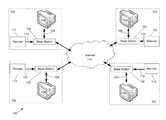
- FIG. 1illustrates a block diagram of a system 100 according to at least one embodiment of the present invention.
- the system 100includes a plurality of hosts 102 .
- Each host 102includes an external display device 104 , such as a television, LCD screen or projector screen, capable of displaying video signals.
- Each external display device 104is connected to a base station 106 .
- the external display device 104 and the base station 106are connected via an HDMI connection; however, it is to be appreciated that the external display device 104 and the base station 106 may be connected via any other type of video connection (e.g., an S-Video or component video connection).
- Each base station 106is coupled to an external network 110 .
- each base station 106may be coupled to the Internet via an IP based Ethernet connection. Also, according to another embodiment, each base station 106 may be coupled to a cloud of a cloud network via the Internet. The operation of the base station 106 will be discussed in greater detail below.
- Each host 102also includes a remote control 112 capable of controlling the operation of the base station 106 .
- the remote control 112is configured to communicate with the base station 106 via Radio Frequency (RF) wireless signals 114 (e.g., a Bluetooth wireless connection); however, it is to be appreciated that the remote control 112 may be configured to communicate with the base station 106 over any type of communication method (e.g., over an infrared connection or even a hardwired connection). The operation of the remote control 112 will be discussed in greater detail below.
- RFRadio Frequency
- FIG. 2illustrates a block diagram 200 of the base station 106 according to at least one embodiment of the present invention.
- base station 106includes a housing 202 .
- the base station 106includes a controller 204 configured to manage the operation of the base station 106 .
- Coupled to the controller 204are a Network Interface Card (NIC) 206 , an RF bi-directional transmitter 208 and data storage 210 .
- NICNetwork Interface Card
- an antenna(not shown) is also coupled to the RF bi-directional transmitter 208 .
- the base station 106may also include a camera 212 , coupled to the controller 204 and protruding from the base station 106 .
- the base station 106may also include a plurality of connections or interfaces.
- base station 106may include an Ethernet connection 214 coupled to the NIC and configured to be coupled to a network 110 (e.g., the Internet), a display output connection 216 (e.g., an HDMI connection) coupled to the controller 204 and configured to provide output display signals to an external display device 104 (e.g., a television, projector, LCD screen etc.), and a power connection 218 coupled to the controller 204 and configured to be connected to a power supply (not shown) (e.g., a utility system).
- Base station 106may include other interface types.
- the NIC 206is configured to be coupled to a network (e.g., to the Internet via the Ethernet connection 214 ) and to send/receive signals from the network.
- the RF bi-directional transmitter 208may be configured (via the antenna) to transmit RF signals to, and receive wireless RF signals from, an external device (e.g., from the remote control 112 ).
- the RF bi-directional transmitteris a half-duplex transmitter in that the transmitter can both transmit and receive signals, but not at the same time.
- the RF signals transmitted and received by the RF bi-directional transmitter 208may be short-range Bluetooth RF signals operating at 2.4 GHz; however, it is to be appreciated that the RF signals transmitted and received by the bi-directional transmitter 208 may be any other type of RF signal (e.g., Wi-Fi signals).
- the camera 212is a digital camera configured to capture video images (e.g., of a user operating the base station 116 ).
- the base station 106may include a controller 204 configured to manage the operation of the base station 106 . Using data stored in associated memory, the controller 204 performs one or more instructions that may result in manipulated data, and the controller 204 monitors and controls operation of the base station 106 .
- the controller 204may include one or more processors or other types of controllers.
- the controller 204is a commercially available, general purpose processor.
- the controller 204performs a portion of the functions disclosed herein on a general purpose processor and performs another portion using an application-specific integrated circuit (ASIC) tailored to perform particular operations.
- ASICapplication-specific integrated circuit
- the data storage 210may include a computer readable and writeable nonvolatile storage medium in which instructions are stored that define a program to be executed by the controller 204 .
- the data storage 210also may include information that is recorded, on or in, the medium, and this information may be processed by the program. More specifically, the information may be stored in one or more data structures specifically configured to conserve storage space or increase data exchange performance.
- the instructionsmay be persistently stored as encoded signals, and the instructions may cause a processor to perform any of the functions described herein.
- the mediummay, for example, be optical disk, magnetic disk or flash memory, among others.
- the controller 204may cause data to be read from the nonvolatile recording medium into another memory (not shown) that allows for faster access to the information by the controller 204 than does the storage medium included in the data storage 210 .
- the memorymay be located in the data storage 210 or somewhere else.
- the controller 204may manipulate the data within the memory, and then copy the data to the medium associated with the data storage 210 after processing is completed.
- a variety of componentsmay manage data movement between the medium and the memory, and the invention is not limited thereto.
- the computer-readable mediummay be non-transitory in that the computer-executable instructions may be stored permanently or semi-permanently on the medium.
- FIG. 3illustrates an external schematic diagram 300 of the base station 106 according to at least one embodiment of the present invention.
- the base station 106comprises a housing 314 .
- FIG. 3illustrates views of a front side 302 , top side 304 , bottom side 306 , left hand side 308 , right hand side 310 , and back side 312 of the base station 106 .
- a plurality of input/output connections 322are provided on the back side 312 of the base station 106 .
- the plurality of input/output connections 322includes at least one Universal Serial Bus (USB) connection, an Ethernet connection, a power connection, a sound input connection, a sound output connection, a microphone input connection and a Video Graphics Array (VGA) connection.
- USBUniversal Serial Bus
- VGAVideo Graphics Array
- the left side 308 , right side 310 and back side 312include ventilation holes 316 configured to prevent overheating of the base station 106 .
- the bottom side 306 of the base station 106may also include ventilation holes (not shown).
- the bottom side 306includes a plurality of legs 318 configured to support the base station 106 when the base station 106 is placed on a hard surface.
- the front side 302 of the base stationincludes a power button 320 coupled to the processor 204 and configured to selectively power on and off the base station 106 .
- the front side 302 of the base stationincludes an indicator light (not shown) coupled to the processor 203 and configured to indicate the operational status of the base station 106 .
- the base station 106is configured to be coupled to an external display device 104 such as a television 104 , via a video display output 216 and coupled to an external network 110 (e.g., the Internet), via an Ethernet network connection 214 .
- the video display output 216includes an HDMI connection.
- the base station 106is also configured to be coupled to a power source (e.g., utility power) via the power connection 218 .
- the base station 106is intended to be placed adjacent to the television 104 (e.g., on top of the television 104 ); however, it is to be appreciated that the base station 106 may be located anywhere as long as its connections to the Internet 110 and the television 104 are maintained and the base station 106 is able to communicate with the remote control 112 .
- the base station 106may be operated by a user to perform typical computer related tasks such as retrieve email, watch online video content, chat, browse the web, etc.
- the base station 106may be configured and operated to provide a system and method for user interaction as described in U.S. patent application Ser. No. 12/416,479 entitled “SYSTEM AND METHOD FOR STREAMLINING USER INTERACTION WITH ELECTRONIC CONTENT,” filed on Apr. 1, 2009, which is herein incorporated by reference in its entirety.
- the base station 106may accept electronic content (e.g., email, video, websites, text, audio, etc.) over the Internet 110 (via the Ethernet connection 214 ), present the electronic content to a user through a graphical user display (displayed on the television 104 via the display output 216 ), and permit the user to interact with the electronic content using at least one I/O device (e.g., the remote 112 ).
- the base station 106may also be configured to organize the graphical user display into a map based user interface and enable the map based user interface to permit interaction with electronic content through the at least one I/O device.
- the map based user interfaceprovides a clear overview of the entire computing environment and searching capability within the environment that may be accessed using the at least one I/O device.
- the base station 106is also configured to display the mapped online digital content as a streamlined representation.
- the streamlined representationis a hierarchical representation that reduces the number of items to select amongst at any stage of navigation, thereby facilitating user access with the at least one I/O device.
- the streamlined representationcomprises at least one card associated with the mapped online digital content.
- the at least one cardis configured to render selectable options customized to the at least one I/O device.
- the streamlined representationcomprises a plurality of cards. Through the use of the I/O device, cards and the graphical user display, a user may be able to operate the base station 106 and interact with content displayed on the television 104 .
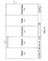
- the user interface “home” screen 470displays a plurality of modes of content 472 .
- the home screen 470contains five modes of content 472 ; however, it is to be appreciated that the home screen may include more or fewer than five modes of content and that the modes of content may differ from the examples discussed below.
- the modes of content 472 accessible via the home screen 470may include “media” 472 a , “connect” 472 b , “web” 472 c , “applications” 472 d , and “channels” 472 e.
- information, programs, features and applicationsmay be grouped into the various modes of content 472 .
- the usermay access the content organized within that mode.
- the media mode 472 amay provide access to a media player to play, view, search and organize media such as music, video, photos, etc.
- the connect mode 472 bmay provide access to features such as, for example, email, voice-over-IP, instant messaging, etc., and the web mode 472 c may provide access to Internet browsing and searching.
- the application mode 472 dmay provide access to, for example, computer applications or programs, such as word processor, spreadsheet, calculator, etc. In one example, these applications or programs may be provided as web-based services rather than programs or applications residing on the base station 106 .
- the channels mode 472 emay provide access to different functionality of the base station 106 , with the different functions or features defined as different channels.
- a channelmay include an alarm clock channel in which the base station 106 is configured to display a clock on the television 104 and can be programmed to activate an alarm, e.g., a sound, piece of music, etc., at a predetermined time.
- an alarm clock channelin which the base station 106 is configured to display a clock on the television 104 and can be programmed to activate an alarm, e.g., a sound, piece of music, etc., at a predetermined time.
- Another example of a channelmay include a “photo frame” channel in which the base station may be configured to display a pre-selected image or set of images, etc. on the television 104 .
- Another example of a channelis a “television” channel, in which the base station 106 is configured to stream Internet television.
- a usermay configure particular Internet television channels (e.g., a news channel, a movie channel, a home and garden channel, etc.) into sub-channels within the channels mode of content 472 ( e ).
- Some or all of the modes of content 472may access, retrieve and/or store information on the Internet.
- some or all of the modes of content 472may access, retrieve and/or store information in a cloud network 474 via the Internet.
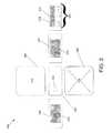
- the different modes of content 472may be displayed as a series of bars across the display screen 510 , as illustrated in FIG. 5 .
- the modes of contentmay be displayed in other configurations, including, for example, a “desktop” and icon configuration, a “dashboard” type display 610 , as illustrated in FIG. 6 , or another configuration, as would be recognized by those skilled in the art.
- each hostmay include an I/O device, such as a remote control 112 , which allows a user to easily and efficiently control various features and functions of the base station 106 and to manipulate content displayed on the television 104 .
- a remote control 112which allows a user to easily and efficiently control various features and functions of the base station 106 and to manipulate content displayed on the television 104 . It is to be appreciated that by providing a base station 106 coupled to a television 104 and a remote control 112 capable of sending information to the base station and operating the base station, certain aspects of the present invention reduce some of the problems discussed above with regards to the use of a computer system connected to a television.
- the useris able to more easily control the base station from a distance (e.g., while the user is located on the other side of a room away from the television) without requiring the use of more typical controls (e.g., a keyboard or mouse) coupled to the base station 106 and/or located adjacent to the base station 106 .
- more typical controlse.g., a keyboard or mouse
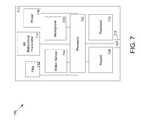
- FIG. 7illustrates a block diagram 700 of the remote control 112 according to at least one embodiment of the present invention.
- the remote control 112includes a processor 702 configured to manage the operation of the remote control 112 . Coupled to the controller are a motion sensor 704 , a microphone 706 , a keypad 708 , a touchpad 710 , a flag 712 , an RF bi-directional transmitter 714 , a power module 716 and a Light Emitting Diode (LED) 718 .
- the remote control 112also includes an antenna (not shown) coupled to the RF bi-directional transmitter 714 .
- the RF bi-directional transmitter 714 and the antennaare located with the processor 702 .
- the RF bi-directional transmitteris a half-duplex transmitter in that the transmitter can transmit and receive signals, but not at the same time.
- the RF bi-directional transmitter 714is configured (via the antenna) to transmit RF signals to, and receive signals from, an external device such as the base station 106 .
- the RF signals received and sent by the remote control 112are Bluetooth RF signals at a frequency of 2.4 GHz; however, it is to be appreciated that the RF signals transmitted and received by the remote control 112 may be any other type of RF signal (e.g., Wi-Fi signals).
- the RF signals sent by the RF bi-directional transmitter 714 to the base station 106include status information pertaining to the operation of the remote control 112 .
- the RF bi-directional transmitter 714periodically broadcasts status bits to the base station 106 to inform the base station 106 of the status of certain operating parameters of the remote control 112 .
- RF signals (including status bits) sent by the RF bi-directional transmitter 714may include signals representing the power remaining in the power module 716 , signals representing the configuration of the remote control 112 generated by the flag 712 , signals representing the firmware status of the remote control 112 and signals representing the pairing status of the remote control 112 .
- the remote control 112may be configured to broadcast any number and any type of status bits.
- RF signals sent by the remote control 112may also be intended to control the operation of the base station 106 .
- RF signals sent by the RF bi-directional transmitter 714may include audio signals generated by the microphone 706 , signals representing the motion or orientation of the remote control 112 generated by the motion sensor 704 , and input signals generated by either the touchpad 710 or keypad 708 in response to operation by a user.
- the motion sensor 704is any type of sensor capable of monitoring the motion or orientation of the remoter controller 112 .
- the motion sensor 704is a 3-axis accelerometer configured to detect motion of the remote control 112 .
- the motion sensor 304is a gyroscope configured to detect the orientation of the remote control 112 .
- the motion sensor 704monitors the motion/orientation of the remote control and, upon sensing a change in the motion or orientation of the remote control 112 , sends an interrupt signal, via the processor 702 and RF bi-directional transmitter 714 to the base station 106 .
- the controller 204(via the RF bi-directional transmitter 208 ) of the base station 106 receives the interrupt signal from the remote control 112 and sends an acknowledgment signal to the remote control 112 (via the RF bi-directional transmitter 208 ).
- the remoter control 112Upon receiving (via the RF bi-directional transmitter 714 ) the acknowledgement signal from the base station 106 , the remoter control 112 sends signals to the base station 106 indicating change in motion or orientation of the remote control 112 .
- the base station 106listens for and receives (via the RF bi-directional transmitter 208 ) the signals from the remote control 112 indicating the change in motion or orientation of the remote control 112 .
- the signals indicating the change in motion or orientation of the remote control 112are passed to the controller 204 , and the controller 204 may be configured to use the motion signals in a variety of ways.
- a change in motion or orientation monitored by the motion sensor 704 of the remote control 112is used to transition the remote control 112 from a standby to a powered state.
- the remote control 112may be configured to enter a standby mode to save power. In the standby mode, power to certain components of the remote control 112 may be limited.
- powermay still be provided to the motion sensor 704 , and the motion sensor 704 may continue to monitor the motion and/or orientation of the remote control 112 , even in standby mode.
- the motion sensor 704may communicate with the processor 702 to power up (wake-up) the remote control 112 .
- the remote control 112may be configured to respond in any number of ways to a change in motion or orientation sensed by the motion sensor 704 .
- motion signals received by the base station 106 from the motion sensor 704may be used to interact with the user interface provided by the base station 106 to the television 104 .
- a specific motion of the remote control 112sensed by the motion sensor 704 , may correlate to specific action in a game being played on the base station 106 by a user.
- a turn of the remote control 112 rightsensed by the motion sensor 704 and communicated to the base station 106
- a turn of the remote control 112 leftsensed by the motion sensor 704 and communicated to the base station 106 , may correlate to a figure in the game moving left.
- a specific motion of the remote control 112may correlate to a specific behavior of a curser in the user interface displayed on the television 104 by the base station 106 .
- a turn of the remote control 112 rightsensed by the motion sensor 704 and communicated to the base station 106
- a turn of the remote control 112 leftsensed by the motion sensor 704 and communicated to the base station 106
- a specific motion of the remote control 112may indicate to the base station 106 that the user is making a selection with the cursor. For example, a vigorous shake of the remote control 112 may indicate to the base station 106 that the user is selecting whatever the cursor is currently pointed at.
- the remote control 112may be able to sense different degrees of changing movement or orientation of the remote control 112 and the base station 106 may be configured to perform different actions in response to the different degrees. For example, in one embodiment, when the remote control 112 is turned to the right at a first degree, the cursor displayed on the television 104 , by the base station 106 , may move to the right at a first speed. When the remote control 112 is turned to the right at a second degree, which is greater than the first degree, the cursor displayed on the television 104 , by the base station 106 , may move to the right at a second speed, greater than the first speed. It is to be appreciated that the base station 106 may be configured to respond in any number of ways to the motion signals communicated from the motion sensor 704 of the remote control 112 to the base station 106 .
- the microphone 706may be any type of circuit capable of receiving audio signals from a user and transmitting the audio signals to the base station 106 via the processor 702 and the RF bi-directional transmitter 714 .
- the microphone 706may be configured to communicate with the base station 106 using a selective repeat ARQ (Automatic Repeat-reQuest) protocol; however, it is to be appreciated that the microphone may be configured to communicate to the base station 106 over any protocol.
- the audio signals transmitted by the microphone to the base station 106may be encoded by a CODEC into 8 bit packets and transmitted at 24 kHz; however, it is to be appreciated that the audio signals may be encoded and transmitted differently.
- the microphone 706receives audio signals from a user.
- the audio signalsare encoded into audio signal packets and each audio signal packet is labeled with a sequence number.
- the microphone 706via the processor 702 and RF bi-directional transmitter 714 sends an interrupt signal to the base station 106 .
- the controller 204via the RF bi-directional transmitter 208 ) receives the interrupt signal and the controller sends (via the RF bi-directional transmitter 208 ) an acknowledgment signal back to the remote control 112 .
- the remoter control 112Upon receiving (via the RF bi-directional transmitter 714 ) the acknowledgement signal from the base station 106 , the remoter control 112 sends encoded audio signals to the base station 106 .
- the base station 106listens for and receives (via the RF bi-directional transmitter 208 ) the encoded audio signals from the remote control 112 . Because each audio signal packet is sequentially numbered, the base station 106 is able to determine if any audio signal packets have been dropped.
- the base station 106sends (via the RF bi-directional transmitter 208 ) additional acknowledgment signals to the remote control 112 . Included in the additional acknowledgment signals are indications of what packets were dropped and need to be resent.
- the processor 702(via the RF bi-directional transmitter 714 ) receives the acknowledgment signals and resends the previously dropped packets along with current audio signal packets to the base station 106 .
- the internal clocks of the remote control 112 and the base station 106may be synchronized (e.g., to 24 kHz) so minimize the loss of data between the remote control 112 and the base station 106 .
- the base station 106may perform a variety of tasks with the received audio signals.
- the audio signals received by the base station 106may be used in a video-chat session in correlation with the camera 212 .
- the audio signals received by the base station 106may be used in a teleconference session.
- the audio signals received by the base station 106may be used to interact with the user interface displayed on the television 104 by the base station 106 . For example, when a user says a specific command, the corresponding audio signals transmitted to the base station 106 , may result in a specific action being taken in the user interface.
- the base station 106may be configured to respond in any number of ways to the audio signals communicated from the microphone 706 of the remote control 112 to the base station 106 .
- a specific sound or even any sound at all, received by the remote control 112 and transmitted to the base station 106may be used to transition the remote control 112 from a standby to a powered state.
- the remote control 112may be configured to enter a standby mode to save power. In the standby mode, power to certain components of the remote control 112 may be limited. However, power may still be provided to the microphone 706 , and the microphone 706 may continue to monitor for audio signals from the user, even in standby mode.
- the microphone 706may communicate with the processor 702 to power up (wake-up) the remote control. Additionally, it is to be appreciated that the remote control 112 may be configured to respond in any number of ways to different sounds sensed by the microphone 706 .
- the present inventionreduces some of the problems discussed above with regards to the use of the computer system connected to a television. For example, because the microphone 706 is actually located within the remote control 112 and not at the computer system itself, a user operating the base station 106 from a distance with the remote control 112 can have the microphone immediately accessible to him and does not need to address issues relating to the microphone receiving audio signals from a distance.
- the power module 716includes at least one battery (not shown).
- the batteryis rechargeable.
- a signal from the power moduleis sent to the processor 702 indicating the amount of available power stored on the battery.
- the processor 702sends signals to certain unused components of the remote control 112 to power down the unused components. For example, if the microphone 706 is not being used, the processor 702 may power down the microphone 706 .
- the processor 702Upon receiving an indication that operation of the microphone 706 is desired (e.g., a signal from the base station 106 indicating that an application using the microphone, such as a video-chat session, has been initialized), the processor 702 sends a signal to the microphone 706 to power up the microphone.
- an indication that operation of the microphone 706 is desirede.g., a signal from the base station 106 indicating that an application using the microphone, such as a video-chat session, has been initialized
- the processor 702Upon receiving an indication that operation of the microphone 706 is desired (e.g., a signal from the base station 106 indicating that an application using the microphone, such as a video-chat session, has been initialized), the processor 702 sends a signal to the microphone 706 to power up the microphone.
- the processor 702may send signals to the components of the remote control 112 to power down the remote control 112 into a standby mode and reduce power consumption. In one embodiment, even in the standby mode, certain components may remain powered. In this way, a user may utilize one of the remaining powered components to power up or wake-up the remote control 112 .
- the touchpad 710 and/or keypad 708may remain powered in standby mode. If a user presses either the touchpad 710 or keypad 708 , the remote control 112 will be powered up. In another example, the microphone 706 remains powered in standby mode.
- the remote control 112will be powered up.
- the motion sensor 704may remain powered in standby mode. If a user moves the remote control 112 in a certain way (e.g., a slight shake), the remote control 112 will be powered up.
- standbye.g.,
- the controller 204sends an acknowledgment signal to the remote control 112 and the controller 204 is able to determine whether the remote control 112 is capable of performing certain functions. For example, if the power status bit, received the controller 204 (via the RF bi-direction transmitter 208 ) indicates that the power available in the power module 716 is below a required threshold, the controller 204 knows not to attempt to activate certain functions of the remote control 112 (e.g., firmware updates as discussed in greater detail below). However, if the power status bit indicates that the power available in the power module 716 is above the required threshold, the controller 204 is free to activate all functions of the remote control 112 .
- the power status bitindicates that the power available in the power module 716 is above the required threshold
- the present inventionprovides a remote control 112 that is generally reliable and can be used consistently to operate the base station 106 , without requiring the frequent replacement or recharging or batteries and/or a fixed hardwired power line to the remote control 112 which would hinder the motion/use of the remote control 112 by the user.
- the LED 718may be any type light emitting circuitry. In one embodiment, the LED is operated by the processor 702 . According to one embodiment, the LED 718 is configured to show a solid light when the remote control 112 is powered on. According to another embodiment, the LED 718 is configured to flash when the remote control 112 is either successfully sending to or receiving information from the base station 106 . For example, in one embodiment, the LED 718 flashes when an acknowledgment signal is successfully received from the base station 106 . According to another embodiment, the LED 718 is able to flash more than one color. For example, in one embodiment, the LED 718 will flash green when then the remote control 112 is in a powered up state and will flash purple when the remote control 112 is in a standby state. It is to be appreciated that the LED 718 may be configured in any way to represent any number of different events
- the remote control 112may include a second LED (not shown).
- the first LED 718 and the second LEDmay be configured to signal different events.
- the first LED 718is configured to flash when a signal is sent to the base station 106 and the second LED is configured to flash when a signal is successfully received from the base station 106 .
- the remote 112may include any number of LEDs that are configured to identify any number of events.
- the keypad 708comprises a plurality of keys (not shown) configured in a plurality of rows and columns.
- the plurality of keysincludes keys associated with text letters and numbers.
- the plurality of keysincludes keys associated with functions of the base station 106 .
- the plurality of keysincludes keys associated with the user interface displayed on the television 104 by the base station 106 .
- the keypad 708may also include pairs of keys that when pressed individually perform one function, but when pressed together, perform an entirely different function.
- each key of the keypad 708is coupled to an Inter-Integrated Circuit (I2C) (not shown).
- I2CInter-Integrated Circuit
- the I2Cis coupled to an I/O expander (not shown) which is coupled to the processor 702 .
- the I2Cis responsible for scanning the rows and columns of keys of the keypad 708 to monitor whether any of the keys have been pressed.
- the I2Csends a signal to the processor 702 , through the I/O expander. The signal received by the processor 702 indicates which key has been pressed.
- the processorsends a signal to the base station, via the RF bi-directional transmitter 714 , indicating which key has been pressed.
- the controller 204 of the base station 106receives the signal, via the RF bi-directional transmitter 208 and sends an acknowledgment signal, via the RF bi-directional transmitter 208 to the processor 702 of the remote control 112 .
- the controller 204may perform a variety of tasks.
- the controller 204may enter the text into the user interface being displayed on the television. For example, if the user is using the user interface as a word processor, the controller 204 will enter the text associated with the pressed key into the word processor document currently displayed. In another example, if the user is using the user interface as a search engine, the base station 106 will enter the text associated with the pressed key into the search box currently displayed.
- the controller 204may initiate the function associated with the pressed key. For example, if a user presses a key associated with a specific application, the controller 204 will open the specific application associated with the pressed key.
- the controller 204may initiate the operation associated with the pressed key. For example, if a user presses a “Back” key while using the user interface as a web browser, the controller 204 will display the previously displayed web page. In another example, if a user presses a search key while using the user interface as a web browser, the controller 204 will open a search box. It is to be appreciated that the keypad 708 may include any number and type of keys and the keys may be defined to perform any number of functions.
- the touchpad 710includes a capacitive or conductive flat surface that is capable of translating the motion and position of a user's fingers to signals useable by the user interface of the base station 106 .
- the signalsare passed to the processor 702 and the processor transmits the touchpad signals to the base station 106 via the RF bi-directional transmitter 714 .
- the controller 204 of the base station 106receives the touchpad signals via the RF bi-directional transmitter 208 and sends an acknowledgement signal via the RF bi-directional transmitter 208 to the remote control 112 . Once the controller 204 has received the touchpad signals, the controller 204 configures the user interface of the base station 106 based on the touchpad signals.
- the touchpadalso includes a depressible switch located beneath the flat surface.
- the depressible switchis located in such a position that when a user presses on the flat surface of the touchpad, the depressible switch is activated.
- a switch signalis passed to the processor 702 and the processor transmits the switch signal to the base station 106 via the RF bi-directional transmitter 714 .
- the controller 204 of the base station 106receives the switch signal via the RF bi-directional transmitter 208 and sends an acknowledgement signal via the RF bi-directional transmitter 208 to the remote control 112 . Once the controller 204 has received the switch signal, the controller 204 configures the user interface of the base station 106 based on the switch signal.
- the touchpad 710 of the remote control 112may allow a user to control, adjust and/or select various functionality of the base station 106 .
- the touchpad 710may be used to provide “hardware navigation” through information, such as menus, icons, etc., of the user interface displayed on the television 104 .
- the touchpadmay sequentially highlight different ones of the modes of content 472 .
- the highlightingmay be achieved by changing the color of the selected mode, and/or by providing a visual indicator, such as a colored bar 576 .
- a highlighted mode 472may be selected by pressing the touchpad 710 , thereby bringing up a new “page” or screen on the user interface corresponding to the selected mode.
- the touchpad 710may similarly be used to select particular functions, features, icons or applications within that mode.
- the touchpad 710is capable of being operated by two fingers (e.g., two finger navigation) of a user.
- the touchpad 710is configured to operate with double down or double up navigation.
- double down or double up navigationmeans that if a user swipes the touchpad in a certain direction and then continues to press in the same direction, or makes another movement in the same direction, the touchpad may automatically begin to scroll in the swiped direction.
- a powered remote control 112 that is currently unpaired with a base station 112transmits, via the RF bi-directional transmitter 714 , periodic pairing requests on a predefined control channel.
- the pairing requestsmay include information about the remote control 112 , such as address information and/or status bits indicating that the remote control would like to be paired with a base station 106 .
- a base station 112 within the transmission range of the remote control 112receives the pairing request from the remote control 112 , via the RF bi-directional transmitter 208 .
- the controller 204 of the base stationtransmits a signal back to the remote control 112 , via the RF bi-directional transmitter 208 , requesting that the remote control 112 reduce the power level of its transmitted pairing signal.
- the controller 204requests that the remote control reduce the power of its pairing signal by 18 dB; however, it is to be appreciated that the power reduction request may be defined differently.
- the processor 702 of the remote controlreduces the power of the pairing signals. If the base station 106 no longer is able to receive the pairing signals from the remote control 112 , the base station 106 determines that the remote control 112 is out of its range and it may continue to listen for pairing signals from other remote controls 112 . According to one embodiment, if a pairing process has failed, the base station 106 may display a message on the television 104 indicating as such.
- the base station 106determines that the remote control 112 is close enough to pair with and the remote control 112 and base station 106 may exchange additional information regarding how the two will communicate in the future. Once a remote control 112 and base station 112 are paired, the base station 112 may display a message on the television 104 indicating as such.
- the signal strength of the pairing signalsmay be so low that it requires the remote control 112 to actually be placed adjacent to (e.g., within 6 inches), or even on top of, the base station 106 , for the base station 106 to receive the pairing signals. This may insure that the remote control 112 is within range of the base station 106 .
- a remote control 112 and a base stationmay immediately provide the remote control 112 with information on how to communicate with the base station 106 .
- Such an embodimentwould ensure that remote controls 112 often used with a particular base station 106 (e.g., in someone's home), would not need to go through the whole pairing process every time a user wanted to use the base station 106 .
- multiple remote controls 112may be paired with a base station 106 at any given time. For example, this may be beneficial when multiple users are utilizing the base station 106 to play a game.
- the base station 106is able to associate received signals with corresponding remote controls 112 .
- the last remote control 112 to send a successful signal to the base station 106is the remote configured to currently control the base station 106 .
- the remote control 112is able to receive over the air firmware updates from the base station 106 .
- the base station 106is configured to periodically receive software updates over the Internet. Included within the software updates may be updated firmware for the remote control 112 .
- the remote control 112is configured to periodically, or on demand, transmit firmware status bits to the base station 106 . In one embodiment, the firmware status bits indicate whether the firmware of the remote control 112 should be updated.
- the base station 106may display a message to the user, via the television, asking the user whether he would like to update the firmware of the remote control 112 . If the user indicates that he would like to update the firmware, the remote control enters a boot loader mode. According to one embodiment, prior to entering boot loader mode, the base station 106 may also check the power status bits received from the remote control 112 (discussed earlier), to confirm that the remote control has enough power in the power module 716 to complete the firmware update.
- a remote control 112begins to transmit a boot loader mode status bit which indicates that the remote control 112 is in boot loader mode.
- the base station 106transmits the firmware update to the remote control 112 . If the update is transmitted in whole, and the remote control 112 determines that there were not any issues with the updating, the remote control 112 exits boot loader mode, operates and boots the remote control 112 from the updated firmware and updates the corresponding status bit accordingly.
- the base station 106displays a message to the user, indicating as such.
- the remote control 112if the firmware update is interrupted (e.g., because the base station 106 is turned off, because the remote control 112 loses power, because the connection between the remote control 112 and the base station 106 is lost, or for any other reason) the remote control 112 will remain in boot loader mode. In one embodiment, while operating in boot loader mode, the remote control 112 boots and operates from protected memory. In this way, even if the firmware update process is interrupted (and therefore the firmware is incomplete or corrupted), use of the remote control 112 may still remain possible through the use of the protected memory.
- the remote control 112after an incomplete firmware update, the remote control 112 will remain in boot loader mode and the boot load status bit indicates as such.
- any base station 106(not only the base station 106 by which the firmware update was started) that the remote control 112 is paired with, may receive the boot loader mode status bit, sense that the remote control 112 is still in boot loader mode, and attempt to finalize the firmware update. For example, if a user attempts to update the firmware of his remote control 112 at home, but the update fails for one reason or another, the user may bring his remote control 112 to another base station 112 , pair the remote with the base station (via the process discussed above) and continue the firmware update process.
- the remote control 112is able to be operated in multiple configurations.
- the flag 712transmits signals indicative of which configuration the remote control 112 is in.
- the flag 712is a mechanical flag that is able to be physically configured in at least two positions.
- the remote control 112transmits (via the RF bi-directional transmitter 714 ) periodically, or as requested, the flag status bit to the base station 106 .
- the controller 204 of the base station 106receives the flag status bit (via the RF bi-directional transmitter), sends an acknowledgment signal to the remote control 112 and configures the user interface of the base station based on the status of the flag 712 .
- FIGS. 8-9Illustrated in FIGS. 8-9 is a remote control 112 capable of operating in dual modes according to one embodiment of the present invention.
- FIG. 8illustrates an external schematic diagram of the remote control 112 according to one embodiment of the present invention.
- FIG. 8illustrates a top side 802 , a bottom side 804 , a left side 806 , a right side 808 , a front side 810 and a back side 812 of the remote control 112 .
- the remote control 112includes a housing comprised of a first portion 814 and a second portion 816 .
- the remote control 112also includes a battery compartment 818 configured to be detachably coupled to the second portion 816 of the housing.
- the battery compartment 818may include a power module 716 as discussed above.
- the battery compartment 818also includes a switch 822 configured to release the battery compartment from the second portion 816 when pressed.
- the front side 810 of the remote controlincludes a touchpad 820 configured to operate as the touchpad 710 discussed above.
- the bottom side 804may also include an LED indicator 824 configured to operate as the LED 718 discussed above.
- the bottom side 804may also include a microphone hole 826 .
- the microphone hole 826may be configured to provide external access to the microphone 706 (as discussed above), allowing the microphone 706 to receive audio signals from a user.
- the right side 808 of the remote control 112may include a set of volume control buttons.
- the volume control buttonsmay include a volume up button 828 , a volume down button 830 , and/or a volume mute button 832 configured to control the volume of audio signals output by the base station 106 .
- the first portion 814 of the remote control 112is slideably connected to the second portion 816 and is able to be moved to two different positions relative to the second portion 816 , configuring the remote control 112 in two different ways.
- the first portion 814 of the remote control 112is slid into a first position directly over the second portion 816 , covering up a keypad (not shown). It is to be appreciated that when the first portion is slid into a first position, only the touchpad 820 is accessible by a user and a keypad (not shown) is not accessible by a user.
- a flage.g., flag 712
- the base station 106receives a signal that the remote control 112 is in a first configuration, the remote control 112 and the base station 106 enter a passive (or closed) mode.
- the remote control 112in the passive mode, is intended to be used by a user to interact with the base station 106 on a limited basis.
- a usermay only desire to view content displayed on the television 104 , and may not desire to actually interact with the content.
- a user who wishes to view online video content on the television 104may only need to select the content and then proceed to view the content.
- the users required interaction with the baste station 106would be limited to the act of selecting the content.
- the remote control 112in the passive mode, is configured so that only the touchpad 820 is accessible by a user.
- a usermay operate the touchpad 820 (as discussed above with relation to touchpad 710 ) to scroll through information of the user interface (e.g., menus, icons, applications etc.)
- information of the user interfacee.g., menus, icons, applications etc.
- the usermay depress the touchpad 820 (as discussed above) to select the desired content. For example, by swiping a finger across the touchpad 820 , a user may scroll through applications displayed on the user interface until a desired Internet television channel is highlighted.
- the Internet television channelis selected and opened and the user may view the content provided by the channel.
- the user interface displayed by the base station 106 on the television 104may also change in response to an indication that the remote control 112 is in passive mode.
- the user interfacein response to the remote control 112 being in passive mode, the user interface may enter a streamlined mode of content.
- a streamlined mode of contentonly pre-determined default information, not requiring the use of any controls other than the touchpad 820 , may be displayed.
- the user interfaceupon the remote control 112 entering passive mode, the user interface may be configured to only display scrollable and selectable information and may eliminate text based or cursor based information (e.g., URL boxes, search boxes etc, text boxes etc.).
- the user interfacemay be configured to only display available TV Internet channels. By swiping a finger across the touchpad 820 , a user may be able to automatically scroll through the available channels (absent a cursor) and select a desired channel by depressing the touchpad 820 . Additionally, it is to be appreciated that the user interface may be configured in any way to make interaction with the user interface in passive mode more simple and efficient.
- certain componentssuch as the microphone 706 , the motion sensor 704 , the RF bi-directional transmitter 714 , the power module 716 and the LED 718 will remain powered and operate as discussed above with relation to FIG. 7 .
- the first portion 814 of the remote control 112is slid into a second position offset from the second portion 816 , revealing a keypad 902 . It is to be appreciated that when the first portion is slid into a second position, both the touchpad 820 and the keypad 902 are accessible by a user.
- a flage.g., flag 712
- the base station 106receives a signal that the remote control 112 is in a second configuration, the remote control 112 and the base station 106 enter an active (or open) mode.
- the remote control 112in the active mode, is intended to be used to interact fully with the user interface of the base station 106 in a full mode of content.
- a usermay operate the touchpad 820 (as discussed above) to scroll through information of the user interface (e.g., menus, icons, applications etc.) and may also use the touchpad 820 to move a cursor.
- the touchpad 820When a desired item of information is highlighted, the user may depress the touchpad 820 (as discussed above) to select the desired content.
- a usermay also operate the keypad 902 (as discussed above in relation to keypad 708 ) to interact with the user interface.
- a usermay utilize the touchpad 820 to move a cursor over specific information, or scroll through information, displayed by the user interface.
- the usermay select the desired information by depressing the touchpad 820 and then interact with the information by using the keypad 902 .
- a user wishing to browse the webmay use the touchpad 820 to move a cursor over an icon representing a web browser.
- the usermay select the icon by depressing the touchpad 820 , upon which a URL text box is displayed by the user interface.
- the keypad 902the user may enter the desired destination URL and submit the URL by again depressing the touchpad 820 .
- the keypad 902may include a plurality of dedicated web buttons, located at the top of the keypad 902 , and configured to mimic the operation of a typical web browser header.
- the keypad 902includes a back dedicated web button 904 , a forward dedicated web button 906 , a search dedicated web button 908 and a URL dedicated web button 910 .
- the keypad 902may include any number and type of dedicated web buttons and the dedicated web buttons may be configured in any variety of ways.
- the forward 906 and back 904 dedicated web buttonsare configured to navigate forward and backward through the history of the current web session respectively.
- the search 908 and URL 910 dedicated web buttonsprovide a way for a user to enter a search or a URL, respectively, with the push of a single button.
- the search 908 and URL 910 dedicated web buttonsmay perform different functions depending on the information that is already, or has been, displayed in the user interface.
- a press of the URL button 910will result in a URL box 1402 being revealed.
- the URL box 1402may be enlarged so that it is relatively easy for a user, operating the base station 106 from a distance, to see characters that have just been typed and so that it is relatively easy for a user to detect any typographical errors.
- the cursor 1403 of the user interface 1400will focus on the URL box 1402 (in preparation for input by the user via the keypad 902 ) and the URL of the page currently being viewed will be selected.
- the URL box 1402may provide selectable suggestions 1404 (e.g., auto-complete suggestions from previously entered URLs) on what URL the user is intending to input.
- selectable suggestions 1404e.g., auto-complete suggestions from previously entered URLs
- a usermay scroll through the suggestions using the touchpad 820 and select a suggestion by depressing the touchpad 820 .
- a press of the search button 908will result in a search box 1502 being revealed.
- the search box 1502may be enlarged so that it is relatively easy for a user, operating the base station 106 from a distance, to see characters that have just been typed and so that it is relatively easy for a user to detect any typographical errors.
- the cursor 1503 of the user interface 1400will focus on the search box 1502 (in preparation for input by the user via the keypad 902 ). If a previous search has been performed within the current web session, the previous query is retained within the search box and is automatically selected.
- the search box 1502may provide selectable suggestions 1504 on what text the user is intending to search. A user may scroll through the suggestions using the touchpad 820 and select a suggestion by depressing the touchpad 820 . According to one embodiment, a user may exit the URL 1402 or search box 1502 by pressing the URL 910 or search 908 button again, respectively (assuming no edits have been made to the box), pressing an escape key on the keypad 902 , or using the touchpad 820 to select an area outside of the box.
- a press of the URL button 910will dismiss the URL box 1402 without taking action. If the user interface 1400 is already displaying a web browser, a URL box 1402 is already displayed and the URL box 1402 has been edited, a press of the URL button 910 will load the new URL and dismiss the URL box 1402 .
- a URL box 1402is already displayed and the search button 908 is pressed, the currently displayed URL box 1402 will change to a search box 1502 , any previously entered text or selections will be retained, and any applicable suggestions will be shown.
- a search box 1502is already displayed and the search box 1502 has not been edited, a press of the search button 908 will dismiss the search box 1502 without taking action. If the user interface 1400 is already displaying a web browser, a search box 1502 is already displayed and the search box 1502 has been edited, a press of the search button 908 will perform the search and dismiss the search box 1502 .
- a search box 1502is already displayed and the URL button 910 is pressed, the currently displayed search box 1502 will change to a URL box 1402 , any previously entered text or selections will be retained, and any applicable suggestions will be shown.
- a new web browser cardwill be opened, the user interface 1400 will zoom in on and focus in on a new URL box 1402 and the cursor 1403 of the user interface 1400 will focus on the new URL box 1402 (in preparation for input by the user via the keypad 902 ).
- the user interface 1400is already displaying a plurality of cards and the search button 908 is pressed, an empty card search box 1502 is opened and the cursor 1503 of the user interface 1400 will focus on the new card search box 1502 (in preparation for input by the user via the keypad 902 ).
- the user interface 1400if the user interface 1400 is already focused in on a single card and the URL button 910 is pressed, the user interface 1400 will zoom out to display the plurality of available cards, a new web browser card will be opened, the user interface 1400 will zoom in on and focus in on a new URL box 1402 and the cursor 1403 of the user interface 1400 will focus on the new URL box 1402 (in preparation for input by the user via the keypad 902 ).
- the user interface 1400if the user interface 1400 is focused on a single card and the search button 908 is pressed, the user interface 1400 will zoom out and display the plurality of available cards, an empty card search box 1502 will be opened and the cursor 1503 of the user interface 1400 will focus on the new card search box 1502 (in preparation for input by the user via the keypad 902 ).
- the present inventionprovides a simple and efficient means of navigating web content displayed on a television 104 .
- a usercan avoid the tedious process of moving a cursor to a specific location to select an icon and can instead, just press a dedicated button.
- the user interface 1400also provides an auto search function. If neither a URL box 1402 or search box 1502 is currently displayed on the user interface 1400 and a user begins to enter text (e.g., through the keypad 708 ), a search box 1502 will automatically be opened, the cursor 1503 will focus on the search box 1502 , and the text being entered by the user is input into the search box 1502 . According to one embodiment, if the user interface recognizes the text entered by a user generally as Internet formatted (e.g., .com, urls, ftp, http, etc.), the user interface will perform an Internet URL search for the entered text.
- Internet formattede.g., .com, urls, ftp, http, etc.
- the user interfacewill search the user interface (e.g., applications, icons, cards, history, etc.) for the entered text.
- the user interfacewill perform a web search for the entered text.
- the remote control 112is easily configurable to switch seamlessly between the active and passive modes to provide easy and efficient operation of the base station 106 while coupled to a television. For example, a user may easily scroll through content utilizing the touchpad 820 in a passive mode and, as a result of not finding what she is looking for, slide open the remote control 112 into active mode to perform a search using the dedicated search button 908 and keypad 902 .
- the base station 106may also be able to inform a user when operation in a different mode may be preferred or even required. For example, while in passive mode, if a user selects information in the user interface requiring further interaction by the user (e.g., through the keypad 708 ), the user interface may display a message to the user indicating that the user must configure the remote control in active mode to proceed.
- another mobile devicemay be configured to act as a proxy for the remote control.
- the mobile deviceis configured to be operated substantially the same as the remote control 112 .
- the touch screen of a mobile phonemay be operated as the touchpad 710 and the keypad of a mobile phone may be operated as the keypad 708 .
- the accelerometer of the mobile phonemay be utilized as the motion sensor 704 and the microphone may be utilized as the microphone 706 .
- the mobile phonecommunicates to the base station through Wi-Fi.
- the base station 106may also be configurable to operate as a dual mode base station 106 .
- the base station 106may be configured to provide different functionality based on the physical configuration of the base station 106 .
- the base station 106may be a computer system configurable to operate in a “laptop” mode (in which the base station 106 has a conventional laptop appearance utilizing conventional laptop controls such as a keyboard, touchpad etc) or an “easel” mode (in which the base station 106 and its display component (not shown) stand vertically forming an inverted “V.”), as described in U.S.
- a remote control 112may be configured to control the operational configuration of the base station 106 .
- a remote control 112may be configured to interact with and operate the user interface of a dual mode base station 106 , as discussed above.
- the base station 106may be configured to operate in a laptop or easel mode depending on the configuration of the remote control 112 .
- the dual mode base station 106is coupled to a television 104 and the first portion 814 of the remote control 112 is slid into a first position (as illustrated in FIG.
- the base station 106operates in easel mode and may be substantially controlled by operation of the touchpad 820 .
- the base station 106when the dual mode base station 106 is coupled to a television 104 and the first portion 814 of the remote control 112 is slid into a second position (as illustrated in FIG. 9 ), the base station 106 operates in laptop mode and may be substantially controlled by operation of the touchpad 820 and keypad 902 .
- a dual mode base station 106may also be operated by controls on the base station 106 itself, absent input from the remote control 112 .
- the dual mode base station 106is coupled to a television 104 and is physically configured in laptop mode, the operation of the base station 106 , and the interaction with the user interface of the base station 106 , may be performed with the controls on the base station 106 (e.g., a touchpad, keyboard, etc.).
- the operation of the base station 106may be performed through interaction with the base station's 106 display component (e.g., a touch screen or touchpad) (not shown).
- the base station's 106 display componente.g., a touch screen or touchpad
- a usermay utilize both a remote control 112 and the controls on the base station 106 itself to operate a dual mode base station 106 .
- the dual-mode base station 106may respond to the last signals (in time) it receives successfully. For example, if a user physically flips the dual mode base station 106 into easel mode, the touchpad 820 of the remote control 112 may be used to interact with and control the dual mode base station 106 as if the first portion 814 of the remote control 112 was in a first position (as illustrated in FIG. 8 ), regardless of the actual configuration of the remote control 112 .
- the touchpad 820 and keypad 902 of the remote control 112may be used to interact with the dual mode base station 106 in laptop mode, regardless of the actual physical configuration of the dual mode base station 106 .
- the display signals sent by the base station 106 to the external display device 104may be configured, in a TV mode, to make interaction with the base station 106 more easy.
- signals intended to be displayed on a conventional computer screenmay not transition well to being displayed on a television 104 (especially when the television 104 is intended to be viewed from a distance).
- the signals sent by the base station 106 to the television 104may be modified.
- the base station 106may operate in TV mode regardless of the configuration of remote control 112 or base station 106 .
- the base station 106may operate in TV mode whether the remote control 112 is in an open or closed figuration or whether the base station 106 is in a laptop or easel mode configuration.
- overscanto crop the edges of the picture region, which historically contain artifacts not intended to be seen by the viewer.
- televisionsmay have an overscan region of up to 7.5% per side. While some televisions provide a way to turn overscan off when viewing content from a computer source, others do not.
- the base station 106may perform overscan correction.
- the base station 106enters TV mode. In TV mode, the base station 106 receives television identification information from the television 104 .
- the base station 106receives television identification information through Extended Display Identification Data (EDID).
- EDIDis a data structure which may include such information as the manufacturer's name, the television's serial number, the product type of the television, the timings supported by the television, display size of the television, pixel mapping data etc.
- the base station 106determines if it has been connected to that specific television 104 before. If the base station 106 has not been connected to the specific television 104 before, the base station 106 initiates an overscan wizard and the user interface of the base station 104 displays the overscan wizard (on the television 104 ).
- FIG. 10illustrates a screen shot 1000 of the overscan wizard interface 1001 displayed on the television 104 by the base station 106 upon activation of the overscan wizard.
- the overscan wizard interface 1001includes a top edge 1002 , a right edge 1004 , a bottom edge 1006 , and a left edge 1008 .
- the overscan wizard interface 1001also includes a first portion 1010 and a second portion 1012 .
- the second portion 1012is 15% of the entire interface 1001 ; however, it is to be appreciated that the second portion 1012 may begin as any portion of the interface 1001 .
- the overscan wizardasks a user to identify the location of each edge of their television screen.
- the overscan correction wizardprompts the user to identify each edge 1002 , 1004 , 1006 , 1008 , one at a time, beginning with the top edge 1002 and moving clockwise; however, it is to be appreciated that the overscan correction wizard may start with any edge and may progress in any order.
- the overscan wizard interface 1001prompts the user (e.g., with text 1014 , diagrams, sound etc.) to move the first portion 1010 of the interface 1001 to the appropriate edge of the screen as indicated by a large arrow 1016 , thus eliminating the second portion 1012 of the interface 1001 .
- the usermay use the keypad 708 of the remote control 112 to move the first portion 1010 .
- the usermay utilize the touchpad 710 to move the first portion 1010 .
- a usermay use the controls on the base station 106 itself (e.g., touch screen, touch pad, keyboard) to move the first portion 1010 .
- the arrow 1016flashes briefly and the first portion 1010 slides in the indicated direction, covering up more of the second portion 1012 .
- the first portion 1010moves in intervals of 1.25% of the interface 1001 (or 9 pixels vertically or 16 pixels horizontally).
- a continuous control movemente.g., a key held down or a double up/down movement
- a usermay then finesse the position of the first portion with discrete control movements as needed.
- the usermay advance the overscan wizard by pressing an enter key (e.g., on the keypad 708 ), depressing the touchpad 710 , or using the touchpad 710 to control a cursor to select the “next” button 1018 .
- an option to return to a previous stepe.g., edge
- each edge settingis stored in an account associated with the user.
- the edge settingsare also associated with a unique identifier for the television 104 on which the overscan wizard was performed. Storing the edge settings with an associated television identifier may allow the base station 106 to automatically recall the edge settings the next time the base station is connected to the same television 104 .
- a usermay not need to use the overscan wizard each time they connect to the same television 104 .
- a usermay also define other display settings such as contrast and brightness.
- the additional display settingsmay also be stored and associated with a specific television 104 , to be recalled by the base station 106 when the base station 106 is reconnected to the specific television 104 and applied by display drivers and/or a rendering engine operated by the controller 204 of the base station 106 .
- the overscan edge settingsare communicated to the display drivers and/or rendering engine of the base station 106 .
- the display drivers and/or rendering enginemay ensure that all information displayed by the base station 106 is maintained within the available screen area determined by the overscan wizard.
- FIG. 11illustrates a flow chart 1100 of the overscan wizard in TV mode according to one embodiment of the present invention.
- a base station 106is connected to a television 104 .
- the base station 106 and television 104are connected via an HDMI connection.
- the base station 106receives television identification information from the television 104 and compares the identification information to identification information of different televisions it has been connected to before. A determination is made whether the television 104 currently connected to the base station 106 has been connected to the base station 106 before.
- the base stationretrieves from memory (e.g., from local memory or from a network cloud) previously stored overscan setting information associated with the television 104 and the user, and adjusts the display configuration of the base station 106 .
- the overscan wizardexits.
- the overscan wizardinitiates.
- the userconfigures the overscan wizard to the top edge of the screen, as discussed above. From block 1108 , the user may choose to store the top edge overscan setting and move on to block 1110 or he may choose to go back to the start of the overscan wizard, at block 1106 .
- the userUpon accepting the top edge overscan setting, at block 1110 , the user configures the overscan wizard to the right edge of the screen, as discussed above. From block 1110 , the user may choose to store the right edge overscan setting and move on to block 1112 or he may choose to go back to the top edge configuration screen, at block 1108 .
- the userUpon accepting the right edge overscan setting, at block 1112 , the user configures the overscan wizard to the bottom edge of the screen, as discussed above. From block 1112 , the user may choose to store the bottom edge overscan setting and move on to block 1114 or he may choose to go back to the right edge configuration screen, at block 1110 .
- the userUpon accepting the bottom edge overscan setting, at block 1112 , the user configures the overscan wizard to the left edge of the screen, as discussed above. From block 1114 , the user may choose to store the left edge overscan setting and move on to block 1116 or he may choose to go back to the bottom edge configuration screen, at block 1112 . At block 1116 , the overscan wizard exits. It is to be appreciated that blocks 1108 to 1114 may be configured in any order
- each piece of informatione.g., cards, channels, applications, icons etc.
- each piece of informationdisplayed by the base station 106 , is configured with a flexible layout allowing it to be adjusted as needed to maximize the available screen area.
- the display drivers and/or rendering engine of the base station 106rearrange the information of the user interface (e.g., cards, icons, applications, channels etc.) displayed on the television 104 to ensure that pixel waste is limited and that no content or controls extend beyond the edges of the screen, interfering with the intended interaction.
- the user interfacee.g., cards, icons, applications, channels etc.
- each piece of information displayed on the user interface of the base station 106is defined with a pixel specification.
- each pixel specificationincludes a combination of springs and struts to indicate how a certain piece of information may be modified and/or scaled.
- the springs and strutsmay define the relationship between the piece of information, other pieces of information and the user interface.
- the display drivers and/or rendering engineBased on the available information (e.g., overscan information, display settings of the television etc.) about the display capabilities of the television 104 and the pixel specifications of the information intended to be displayed on the television 104 , in TV mode the display drivers and/or rendering engine modify and arrange the desired information so that the pieces of information are adequately displayed on the available display area of the television 104 .
- available informatione.g., overscan information, display settings of the television etc.
- the display drivers and/or rendering engine of the base station 106may also specifically manipulate components of the user interface.
- the base station 106when the base station 106 is coupled to the television 104 , header portions of the user interface, are hidden, so that the user interface may take advantage of every available pixel on the television 104 for desired content.
- a header portion 1202is typically located at the top edge 1203 of the user interface 1200 and may include operational information related to the content displayed on the user interface (e.g., search tools (not shown), system messages 1206 , navigation buttons 1208 etc.).
- the header portion 1202is hidden until its use is required. For example, in one embodiment, when the header portion 1202 is hidden, a user who requires the use of the header portion 1202 may move the cursor 1204 to the top edge 1203 of the screen (e.g., at the topmost row of pixels). Once the cursor 1204 is at the top edge 1203 of the screen, a thin bar (not shown) appears across the topmost row of pixels, indicating the presence of a hidden header portion 1202 . In one embodiment, if the user maintains the cursor 1204 at the top edge 1203 of the screen for a predetermined period of time, the header portion 1202 appears.
- movement of the cursor 1204in addition to maintaining the cursor 1204 at the top of the screen, in order for the header portion 1202 to reappear, movement of the cursor 1204 must remain below a minimum threshold.
- movement of the cursor 1204is calculated as a linear moving average of the last quarter of a second.
- the minimum threshold speedis 80 pixels per second.
- the movement of the cursor 1204may be calculated in any way and the minimum threshold may be defined as any amount of time.
- a usermay activate the header portion 1202 by clicking on the thin bar at the top of the screen (e.g., with the touchpad 710 ).
- the header portion 1202slides into the user interface 1200 , pushing the rest of the displayed information downward and causing the information at the bottom of the user interface 1200 to move off of the screen.
- the header portion 1202slides over the displayed information at the top edge 1203 and does not displace any of the other information.
- once the header portion 1202 is activatedit remains visible while it is being used. For example, the header portion 1202 remains visible when a text field (e.g., of a search or URL box) is active, when a drop down menu within the header portion 1202 is currently open, or when a system message 1206 , requiring action by the user, is displayed.
- a text fielde.g., of a search or URL box
- the header portion 1202slides off screen
- the base station 106may hide the cursor 1204 as the user operates the user interface of the base station mainly through use of the touchpad 710 (e.g., by automatic scrolling).
- a usermay still have a need for the use of the cursor 1204 (e.g., when making a selection in active or laptop mode).
- a usermay operate a touchpad (e.g., of the remote control 112 or the base station 106 itself) to manipulate a cursor 1204 in order to interface with the user interface of the base station 106 .
- the base station 106may also be configured to modify a cursor 1204 when the base station 106 is coupled to the television 104 and is configured in active or laptop mode.
- a cursor 1204 operated by a user to interface with a base station 106may be modified to be more easily operated by a user operating the base station 106 from a distance (via a television 104 ).
- the display drivers and/or rendering engine of the base station 106may also constrain a cursor 1204 to the same available display output. In this way, the cursor may be prevented from becoming lost beyond the edge of the television screen and information near the television screen edges (e.g., header buttons and scrollbars) may be more easily used.
- cursorsare traditionally small. However, while this may be adequate when a user is operating the computer system from a short distance directly in front of a computer screen, the small cursor may be difficult to follow when a user is operating the computer system from a distance (e.g., from the other side of a room). Therefore, according to at least one embodiment of the present invention, once the base station 106 is coupled to a television 104 , the display drivers and/or rendering engine of the base station 106 may increase the size of cursor 1204 . For example, in one embodiment, the cursor 1204 is increased by 50%; however, it is to be appreciated that the cursor 1204 may be increased by any amount.
- the display drivers and/or rendering engine of the base station 106hide the cursor 1204 after a period of inactivity.
- the cursor 1204is hidden after a 10 second period of inactivity; however, it is to be appreciated that the period of inactivity may be defined as any amount of time.
- the display drivers and/or rendering engine of the base station 106may highlight the cursor 1204 briefly upon the cursor 1204 being initially moved. For example, according to one embodiment, when the cursor 1204 is first moved, an animated wave-like effect, emanating from the cursor 1204 , may be displayed, indicating to the user the position of the cursor 1204 . It is to be appreciated that any highlighting effect may be used to signal the position of the cursor 1204 .
- certain messages 1206 from the base station 106may be displayed on the television 104 .
- these messages 1206may require action by the user.
- a message 1206e.g., via a dialogue bubble
- a message 1206may appear on the screen informing the user that the remote control 112 firmware requires updating, that another user is requesting a video chat, or even that the battery power of the remote control 112 is running low.
- a hidden cursor 1204is configured to automatically jump (warp) to the location of any messages 1206 from the base station 106 displayed on the television 104 .
- the hidden cursor 1204not only will the hidden cursor 1204 jump to the location of the message 1206 , but the cursor 1204 will be located in such a position that a single operation by the user will dismiss the message 1206 .
- content being viewed by the useris interrupted by a message 1206 from the base station 106 informing the user that a friend has shared their photo set and inquiring whether the user wishes to view the set now or look at it later.
- the hidden cursor 1204automatically positions itself at the location of the message 1206 , the cursor 1204 is highlighted (as discussed above), and the cursor 1204 is automatically positioned over a button 1210 , which when pressed, indicates to the base station 106 that the user wishes to view the photo set.
- a simple operatione.g., pressing on the touchpad 710 or pressing an “Enter” key on the keypad 708
- the usercan respond affirmatively to the message and quickly dismiss the message 1206 .
- a usermay press a different key (e.g., an “Escape” key on the keypad 708 ) to respond negatively to the message and also quickly dismiss the message 1206 .
- only hidden cursors 1204will automatically jump to messages 1206 from the base station 106 , so as not to interfere with a non-hidden cursor 1204 currently being used by the user.
- all cursors 1204may be configured to automatically jump to the location of a system message 1206 .
- Inputting text to the base station 106 from a distance (via the remote control 112 )can be difficult without adequate feedback.
- a remote control 112instead of a conventional standard size keyboard, to enter text into the user interface from a distance, a user may need to continuously change their gaze by looking up at the screen and then down at the remote control 112 while typing, in order to ensure the accurate input of the text. This may be a time intensive, inefficient and even frustrating process
- the display drivers and/or rendering engine of the base station 106are configured to display large and immediate feedback for as much text input as possible, thereby making it relatively easy to see the characters that have just been typed and making it possible to more easily confirm typographical errors.
- a text field 1302 in the user interface 1300is selected by a user and the user begins to enter text
- an overlay 1304containing recently typed characters 1306 appears.
- the overlay 1304is transient, appearing immediately when a character is typed, and disappearing again after a predetermined period of time without any additional input or upon movement of the cursor (not shown).
- the overlay 1304disappears after two seconds without any additional input; however, it is to be appreciated that the overly 1304 may be configured to disappear after any amount of time without additional input.
- the overlay 1304even when the overlay 1304 disappears (e.g., because of inactivity), the text previously entered into the overlay 1304 will not clear and will continue to be displayed when the overlay 1304 is again displayed.
- the overlay 1304will only clear when whitespace is entered by the user, or when any other form of input alters the position of the cursor. As a result, until a space or other input clears the overlay 1304 , a “backspace” key of the keypad 708 may be used to make corrections as needed.
- the overlay 1304appears in the lower middle area of the user interface 1300 , where it is least likely to obscure the selected text field 1302 and where it is relatively easy to view by a user glancing up from the remote control 112 .
- the overlay 1304grows as necessary.
- the overlay 1304will display an ellipsis at the beginning should the input exceed the width of the screen.
- any characters entered into the overlay 1304are mirrored within the text field 1302 .
- the characters entered into the overlay 1304are mirrored instantly into within the text field 1302 .
- the overlay 1304may be utilized in TV mode whenever a user wishes to enter text into a text field 1302 .
- cursors, text, search and URL boxesmay all be enlarged by the display drivers and/or rendering engine of the base station 106 to improve their ease of use while the base station 106 is being operated from a distance.
- the display drivers and/or rendering engine of the base station 106may also zoom into the entire layout of a desired page. For example, in order to take advantage of all the available pixels available on a television 104 , the display drivers and/or rendering engine of the base station 106 zooms pages, using full page zoom, to fit the width of the screen.
- pagesare zoomed as much as possible without requiring horizontal page scrolling, up to a maximum of 150% of their native size.
- the display drivers and/or rendering enginemay be configured to zoom into the pages at any level.
- zooming into the pageincreases the size of the text on the page, so that it is readable at a distance.
- zooming into the pagealso increases the relative size of any links on the page, making the links easier to read and easier to navigate when using the touchpad 710 of the remote control 112 .
- the usermay still be able to manually control the level of zoom displayed in the user interface (e.g., via shortcut keys on the keypad 708 or actual controls displays in the user interface).
- the base station 106may receive information about the television 104 .
- the information sent from the televisionmay also be used to adjust settings in the base station 105 .
- the base station 106when the base station 106 is connected to the television 104 (via an HDMI connection), the base station 106 enters TV mode.
- the base stationmay receive display capabilities from the television (e.g., overscan area, pixel settings, refresh rate, brightness and contrast settings etc.) and configure the video output display signals sent from the base station 106 to the television 104 based on the display capabilities. For example, in one embodiment, if the television 104 sends overscan information to the base station 106 , the base station 106 can configure the layout of the user interface without running the overscan wizard.
- the base station 106can configure the layout of the user interface to best utilize all of the available pixels. It is to be appreciated that the base station 106 may receive any type of display information from the television 104 and may adjust its display settings to provide the best display possible on the television 104 .
- the base station 106may also receive content type display information over the network 110 associated with the type of content that is currently being displayed on the television 104 .
- the content type display information received by the base station 106may indicated what the user is currently viewing.
- the display drivers and/or rendering engine of the base stationmay adjust the display settings of the base station 106 accordingly.
- the display drivers and/or rendering engine of the base station 106may adjust the brightness and contrast settings of the base station 106 along with the layout of the user interface to provide the most efficient and best quality video signals possible to the television 104 .
- the user interface of the base station 106may be configured in any way in response to any type of content type display information.
- the base station 106may also receive content subject matter display information over the network 110 associated with the subject matter of the content that is currently being displayed on the television 194 .
- the display drivers, rendering engine and controller 204 of the base stationpresent related material to the user.
- the base station 106may receive information over the network 110 that the user is currently viewing sports related material in the web browser.
- the base station 106may display additional sports related content or sports related advertising that the user may be interested in.
- the base station 106may receive information that the user is currently viewing a certain television program (e.g., either through online video or other broadcast means such as cable or satellite television). In response, the base station 106 may display additional content or advertisements related to the television program.
- the base station 106may provide audio feedback for certain actions taken by the user and/or the base station 106 . This helps the user to better appreciate their interaction with the base station. For example, in one embodiment, the base station 106 plays a sound when a new system message 1206 is displayed, when the cursor 1204 is highlighted, or when a new text box is opened. However, it is to be appreciated that the base station 106 may be configured to play any defined sound for any action. Through the sounds, the user may quickly be able to determine what action the base station 106 has just taken and/or what actions the user must perform.
- the present inventionprovides a computer system capable of being coupled to an external display device that provides efficient use of the computer system through a remote control and reduces the problems with external display device/computer system compatibility through display signal modification.
Landscapes
- Engineering & Computer Science (AREA)
- Multimedia (AREA)
- Signal Processing (AREA)
- Human Computer Interaction (AREA)
- General Engineering & Computer Science (AREA)
- Two-Way Televisions, Distribution Of Moving Picture Or The Like (AREA)
- Mobile Radio Communication Systems (AREA)
Abstract
Description
Claims (18)
Priority Applications (2)
| Application Number | Priority Date | Filing Date | Title |
|---|---|---|---|
| US12/910,333US8938753B2 (en) | 2010-05-12 | 2010-10-22 | Configurable computer system |
| PCT/US2011/057316WO2012054850A2 (en) | 2010-10-22 | 2011-10-21 | Configurable computer system |
Applications Claiming Priority (2)
| Application Number | Priority Date | Filing Date | Title |
|---|---|---|---|
| US29/361,526USD654908S1 (en) | 2010-05-12 | 2010-05-12 | Slideably openable remote control device for a computer or other electronic device |
| US12/910,333US8938753B2 (en) | 2010-05-12 | 2010-10-22 | Configurable computer system |
Related Parent Applications (1)
| Application Number | Title | Priority Date | Filing Date |
|---|---|---|---|
| US29/361,526Continuation-In-PartUSD654908S1 (en) | 2010-05-12 | 2010-05-12 | Slideably openable remote control device for a computer or other electronic device |
Publications (2)
| Publication Number | Publication Date |
|---|---|
| US20110283314A1 US20110283314A1 (en) | 2011-11-17 |
| US8938753B2true US8938753B2 (en) | 2015-01-20 |
Family
ID=45975917
Family Applications (1)
| Application Number | Title | Priority Date | Filing Date |
|---|---|---|---|
| US12/910,333Active2031-03-03US8938753B2 (en) | 2010-05-12 | 2010-10-22 | Configurable computer system |
Country Status (2)
| Country | Link |
|---|---|
| US (1) | US8938753B2 (en) |
| WO (1) | WO2012054850A2 (en) |
Cited By (3)
| Publication number | Priority date | Publication date | Assignee | Title |
|---|---|---|---|---|
| USD731533S1 (en)* | 2013-01-05 | 2015-06-09 | Samsung Electronics Co., Ltd. | Display screen or portion thereof with graphical user interface |
| USD732070S1 (en)* | 2013-01-04 | 2015-06-16 | Samsung Electronics Co., Ltd. | Display screen or portion thereof with graphical user interface |
| US11672934B2 (en) | 2020-05-12 | 2023-06-13 | Covidien Lp | Remote ventilator adjustment |
Families Citing this family (19)
| Publication number | Priority date | Publication date | Assignee | Title |
|---|---|---|---|---|
| US20120081299A1 (en)* | 2010-10-04 | 2012-04-05 | Verizon Patent And Licensing Inc. | Method and apparatus for providing remote control via a touchable display |
| US11265510B2 (en) | 2010-10-22 | 2022-03-01 | Litl Llc | Video integration |
| US8760488B2 (en) | 2010-10-22 | 2014-06-24 | Litl Llc | Video integration |
| JP2013106315A (en)* | 2011-11-16 | 2013-05-30 | Toshiba Corp | Information terminal, home appliances, information processing method, and information processing program |
| EP2613227B1 (en)* | 2012-01-06 | 2020-04-29 | Samsung Electronics Co., Ltd | Input apparatus and control method thereof |
| JP2013242357A (en)* | 2012-05-18 | 2013-12-05 | Ricoh Co Ltd | Information processing apparatus, information processing method, and program |
| JP5905783B2 (en)* | 2012-06-28 | 2016-04-20 | シャープ株式会社 | Image display system |
| CN103793302A (en)* | 2012-10-31 | 2014-05-14 | 英业达科技有限公司 | Debugging device |
| US10572267B2 (en)* | 2012-11-09 | 2020-02-25 | Insyde Software Corp. | Bios user interface control using mobile device |
| JP2015019238A (en)* | 2013-07-10 | 2015-01-29 | 船井電機株式会社 | Electronic apparatus system |
| WO2015100340A1 (en)* | 2013-12-26 | 2015-07-02 | Tandem Diabetes Care, Inc. | Safety processor for wireless control of a drug delivery device |
| EP4250313A3 (en) | 2013-12-26 | 2023-11-22 | Tandem Diabetes Care, Inc. | Integration of infusion pump with remote electronic device |
| KR102215072B1 (en)* | 2014-01-03 | 2021-02-10 | 삼성전자주식회사 | Display apparatus and Method for controlling display apparatus thereof |
| JP6608579B2 (en)* | 2014-04-03 | 2019-11-20 | 株式会社ミツトヨ | Measuring instrument |
| US9514639B2 (en)* | 2014-06-20 | 2016-12-06 | Ray Enterprises Inc. | Universal remote control user interface for discrete control of multiple devices |
| USD772913S1 (en)* | 2015-05-21 | 2016-11-29 | Layer3 TV, Inc. | Display screen or portion thereof with graphical user interface |
| KR102355624B1 (en)* | 2015-09-11 | 2022-01-26 | 엘지전자 주식회사 | Mobile terminal and method for controlling the same |
| GB201516978D0 (en)* | 2015-09-25 | 2015-11-11 | Mclaren Applied Technologies Ltd | Device control |
| CN118819333A (en)* | 2021-05-24 | 2024-10-22 | 合肥元顿传感科技有限公司 | Screen display control method |
Citations (271)
| Publication number | Priority date | Publication date | Assignee | Title |
|---|---|---|---|---|
| US3468576A (en) | 1968-02-27 | 1969-09-23 | Ford Motor Co | Magnetic latch |
| US4709342A (en) | 1983-08-03 | 1987-11-24 | Hitachi, Ltd. | Tactile sensing apparatus |
| US4939514A (en) | 1987-12-22 | 1990-07-03 | Seiko Instruments, Inc. | Foldable data collecting and processing device |
| USD333636S (en) | 1991-12-12 | 1993-03-02 | Issa Darrell E | Transmitter for a vehicle alarm |
| US5200913A (en) | 1990-05-04 | 1993-04-06 | Grid Systems, Inc. | Combination laptop and pad computer |
| US5231381A (en) | 1989-10-02 | 1993-07-27 | U.S. Philips Corp. | Data processing system with a touch screen and a digitizing tablet, both integrated in an input device |
| US5268817A (en) | 1990-04-27 | 1993-12-07 | Kabushiki Kaisha Toshiba | Portable computer with keyboard and having display with coordinate input tablet rotatably mounted to face either toward or away from keyboard when closed over keyboard |
| US5278362A (en) | 1991-12-26 | 1994-01-11 | Nihon Kaiheiki Industrial Company, Ltd. | Push-button switch with display device |
| US5319386A (en) | 1992-08-04 | 1994-06-07 | Gunn Gary J | Ideographic character selection method and apparatus |
| US5383735A (en) | 1993-07-23 | 1995-01-24 | Smith Corona Corporation | Miniature keyboard with sliding keys |
| US5515345A (en) | 1994-08-23 | 1996-05-07 | Jeane K. Barreira | Control unit for automobile audio system |
| US5541372A (en) | 1992-06-15 | 1996-07-30 | U.S. Philips Corporation | Force activated touch screen measuring deformation of the front panel |
| US5666113A (en) | 1991-07-31 | 1997-09-09 | Microtouch Systems, Inc. | System for using a touchpad input device for cursor control and keyboard emulation |
| US5673066A (en) | 1992-04-21 | 1997-09-30 | Alps Electric Co., Ltd. | Coordinate input device |
| US5712760A (en) | 1996-01-26 | 1998-01-27 | Texas Instruments Incorporated | Compact foldable keyboard |
| USD391927S (en) | 1997-05-13 | 1998-03-10 | Digital Equipment Corporation | Notebook personal computer |
| USD392944S (en) | 1996-09-30 | 1998-03-31 | Issa Darrell E | Remote control transmitter |
| USD395868S (en) | 1997-01-23 | 1998-07-07 | Kabushiki Kaisha Toshiba | Electronic computer |
| US5790371A (en) | 1994-07-08 | 1998-08-04 | Siemens Aktiengesellschaft | Modular and extendible electronic working surface |
| US5793355A (en) | 1997-03-03 | 1998-08-11 | Compaq Computer Corporation | Portable computer with interchangeable pointing device modules |
| US5796575A (en) | 1992-12-21 | 1998-08-18 | Hewlett-Packard Company | Portable computer with hinged cover having a window |
| USD399526S (en) | 1997-12-24 | 1998-10-13 | Brady Wilson C | Electronic book |
| US5825352A (en) | 1996-01-04 | 1998-10-20 | Logitech, Inc. | Multiple fingers contact sensing method for emulating mouse buttons and mouse operations on a touch sensor pad |
| US5841631A (en) | 1996-06-14 | 1998-11-24 | Texas Instruments Incorporated | Latch block control for media bay module |
| US5847698A (en) | 1996-09-17 | 1998-12-08 | Dataventures, Inc. | Electronic book device |
| US5854625A (en) | 1996-11-06 | 1998-12-29 | Synaptics, Incorporated | Force sensing touchpad |
| US5900848A (en) | 1996-05-17 | 1999-05-04 | Sharp Kabushiki Kaisha | Information processing apparatus |
| US5949643A (en) | 1996-11-18 | 1999-09-07 | Batio; Jeffry | Portable computer having split keyboard and pivotal display screen halves |
| USD416003S (en) | 1997-08-27 | 1999-11-02 | Vadem | Notebook computer housing |
| US5987704A (en) | 1998-04-15 | 1999-11-23 | Apple Computer, Inc. | Dual axis hinge apparatus with braking mechanism |
| US6005767A (en) | 1997-11-14 | 1999-12-21 | Vadem | Portable computer having articulated display |
| US6011592A (en) | 1997-03-31 | 2000-01-04 | Compaq Computer Corporation | Computer convergence device controller for managing various display characteristics |
| US6034672A (en) | 1992-01-17 | 2000-03-07 | Sextant Avionique | Device for multimode management of a cursor on the screen of a display device |
| US6055478A (en)* | 1997-10-30 | 2000-04-25 | Sony Corporation | Integrated vehicle navigation, communications and entertainment system |
| US6067224A (en) | 1997-10-03 | 2000-05-23 | Fujitsu Limited | Portable information processing apparatus with an improved acoustic effect |
| US6067081A (en) | 1996-09-18 | 2000-05-23 | Vdo Adolf Schindling Ag | Method for producing tactile markings on an input surface and system for carrying out of the method |
| US6067074A (en) | 1986-08-27 | 2000-05-23 | Texas Instruments Incorporated | Keyboard with flexible display and prompt capability |
| KR20000036647A (en) | 2000-03-24 | 2000-07-05 | 유우영 | Method for searching using image |
| US6118435A (en) | 1997-04-10 | 2000-09-12 | Idec Izumi Corporation | Display unit with touch panel |
| US6118449A (en) | 1997-06-25 | 2000-09-12 | Comet Systems, Inc. | Server system and method for modifying a cursor image |
| US6222507B1 (en) | 1997-11-19 | 2001-04-24 | Nec Corporation | Compact personal computer having a plurality of display panels |
| US6223393B1 (en) | 1999-07-09 | 2001-05-01 | International Business Machines Corporation | Redundant hinge element for a notebook computer |
| DE19952486A1 (en) | 1999-10-29 | 2001-05-03 | Joachim Schweizer | Presentation device has lap-top, main and second screens, controller that rotates image on main screen by 180 degrees when main screen is pivoted by 220 degrees |
| TW434606B (en) | 1999-02-11 | 2001-05-16 | Mitac Int Corp | Touch pad apparatus capable of moving in parallel and up/down and having a touch pad button switch installed at the bottom side |
| US6243080B1 (en) | 1998-07-14 | 2001-06-05 | Ericsson Inc. | Touch-sensitive panel with selector |
| US6262885B1 (en) | 1998-11-19 | 2001-07-17 | International Business Machines Corp. | Portable computing device having a display movable thereabout |
| US6266236B1 (en) | 1997-08-27 | 2001-07-24 | Vadem | Apparatus and method for connecting and articulating display in a portable computer having multiple display orientations |
| US6275376B1 (en) | 1998-10-16 | 2001-08-14 | Samsung Electronics Co., Ltd. | Portable computer display tilt/swivel mechanism and method |
| US6295038B1 (en) | 1998-04-16 | 2001-09-25 | Carlton S. Rebeske | Laptop computer |
| US6302612B1 (en) | 1998-03-16 | 2001-10-16 | International Business Machines Corporation | Pivotally extensible display device |
| US6323846B1 (en) | 1998-01-26 | 2001-11-27 | University Of Delaware | Method and apparatus for integrating manual input |
| US6327482B1 (en) | 1998-05-28 | 2001-12-04 | Nec Corporation | Mobile radio apparatus with auxiliary display screen |
| EP0588210B1 (en) | 1992-09-08 | 2001-12-12 | Hitachi, Ltd. | Portable radio telephone set |
| USD452238S1 (en) | 1999-12-27 | 2001-12-18 | Kabushiki Kaisha Toshiba | Electronic computer |
| US20020005818A1 (en) | 2000-06-27 | 2002-01-17 | Bruzzone Raul Alberto | Portable processing device comprising a plurality of screen modules of which at least one folding screen module folds over a main screen module |
| US6343006B1 (en) | 1998-11-20 | 2002-01-29 | Jerry Moscovitch | Computer display screen system and adjustable screen mount, and swinging screens therefor |
| US20020021258A1 (en) | 2000-03-29 | 2002-02-21 | Eric Koenig | Multi-task interactive wireless telecommunications device |
| US6377444B1 (en) | 1999-11-30 | 2002-04-23 | Ingersoll-Rand Company | Hinged housings for electronic devices |
| WO2002035461A1 (en) | 2000-10-27 | 2002-05-02 | Elo Touchsystems, Inc. | Dual sensor touchscreen utilizing projective-capacitive and force touch sensors |
| US6388655B1 (en) | 1999-11-08 | 2002-05-14 | Wing-Keung Leung | Method of touch control of an input device and such a device |
| US6429846B2 (en) | 1998-06-23 | 2002-08-06 | Immersion Corporation | Haptic feedback for touchpads and other touch controls |
| USD462069S1 (en) | 2001-04-27 | 2002-08-27 | Webemage Corp. | Remote control |
| USD463797S1 (en) | 2001-07-23 | 2002-10-01 | Apple Computer, Inc. | Computing device |
| US6464195B1 (en) | 1997-12-04 | 2002-10-15 | Raymond Hildebrandt | Ergonomic mounting for computer screen displays |
| US6504530B1 (en) | 1999-09-07 | 2003-01-07 | Elo Touchsystems, Inc. | Touch confirming touchscreen utilizing plural touch sensors |
| US6510049B2 (en) | 2000-01-06 | 2003-01-21 | Rosen Products Llc | Adjustable display monitor unit |
| US20030048595A1 (en) | 2001-09-10 | 2003-03-13 | Omniwin Corp. | Collapsible keyboard |
| US20030109232A1 (en) | 2001-12-08 | 2003-06-12 | Samsung Electronics Co., Ltd. | Camera lens mounting device of folder type telephone |
| USD476326S1 (en) | 2002-01-09 | 2003-06-24 | Sharp Kabushiki Kaisha | Computer |
| USD479708S1 (en) | 2002-04-03 | 2003-09-16 | Shih-Ming Hwang | Remote control |
| US6628267B2 (en) | 1998-03-27 | 2003-09-30 | International Business Machines Corporation | Flexibly interfaceable portable computing device |
| US6639584B1 (en) | 1999-07-06 | 2003-10-28 | Chuang Li | Methods and apparatus for controlling a portable electronic device using a touchpad |
| US6642909B1 (en) | 2000-08-07 | 2003-11-04 | Anthony R. Oliva | Personal electronic book providing keypad and readable and writable CD drives |
| US20030206394A1 (en) | 2000-12-16 | 2003-11-06 | Kamran Ossia | Multi-mode handheld computer and remote control |
| US6661426B1 (en) | 1999-09-25 | 2003-12-09 | Koninklijke Philips Electronics N.V. | User interface generation |
| US6659516B2 (en) | 2001-01-05 | 2003-12-09 | Apple Computer, Inc. | Locking system for a portable computer |
| US6665175B1 (en) | 2002-02-04 | 2003-12-16 | Deboer Carrie | Computer having a monitor that has multiple degrees of freedom with respect to the base of the computer |
| US20040001049A1 (en) | 2002-06-27 | 2004-01-01 | Oakley Nicholas W. | Multiple mode display apparatus |
| US6697055B1 (en) | 1995-11-16 | 2004-02-24 | Edward Bullister | Multifunctional portable computing device with special housing |
| US20040041800A1 (en) | 2002-09-04 | 2004-03-04 | Daniels John James | Thin, lightweight, flexible, bright, wireless display |
| US6721881B1 (en) | 2000-09-29 | 2004-04-13 | Dell Products L.P. | System and method for determining if a display device configuration has changed by comparing a current indicator with a previously saved indicator |
| USD491177S1 (en) | 2002-12-31 | 2004-06-08 | Apple Computer, Inc. | Computing device |
| USD491936S1 (en) | 2002-11-12 | 2004-06-22 | Aplux Communications Ltd. | Tablet personal computer |
| US20040125086A1 (en) | 2002-12-30 | 2004-07-01 | Hagermoser Edward S. | Touch input device having removable overlay |
| US6771494B2 (en) | 2001-12-17 | 2004-08-03 | Toshiba America Information Systems, Inc. | Portable computer usable in laptop and tablet configurations |
| USD494162S1 (en) | 2003-08-19 | 2004-08-10 | Kabushiki Kaisha Toshiba | Electronic computer |
| USD495674S1 (en) | 2003-07-04 | 2004-09-07 | Lg Electronics Inc. | Mobile phone |
| US6788527B2 (en) | 2002-05-31 | 2004-09-07 | Hewlett-Packard Development Company, L.P. | Tablet computer keyboard and system and method incorporating same |
| USD495694S1 (en) | 2003-06-11 | 2004-09-07 | Michael J. Chase | Edge terminal device |
| US20040196268A1 (en) | 2003-04-07 | 2004-10-07 | Darfon Electronics Corp. | Input module and operating method thereof |
| US20040203535A1 (en) | 2003-04-14 | 2004-10-14 | Samsung Electronics Co., Ltd. | Mobile phone having a rotational camera lens housing |
| US6819304B2 (en) | 2001-10-11 | 2004-11-16 | International Business Machines Corporation | Adjustable display device with display adjustment function and method therefor |
| US20040228076A1 (en) | 2003-05-13 | 2004-11-18 | Clapper Edward O. | Sliding screen emerging keyboard |
| US6829140B2 (en) | 2001-12-17 | 2004-12-07 | Toshiba America Information Services, Inc. | Portable computer usable in laptop and tablet configurations |
| WO2004107146A2 (en) | 2003-05-30 | 2004-12-09 | Therefore Limited | A data input method for a computing device |
| US20050018396A1 (en) | 2003-06-30 | 2005-01-27 | Kabushiki Kaisha Toshiba | Electronic apparatus including optical guide that guides light from light-emitting diode to outside of housing |
| US6859219B1 (en) | 1999-10-08 | 2005-02-22 | Gateway, Inc. | Method and apparatus having multiple display devices |
| US20050041378A1 (en) | 2003-08-21 | 2005-02-24 | Tomohiro Hamada | Electronic apparatus having a housing |
| US20050063145A1 (en) | 2003-09-18 | 2005-03-24 | Homer Steven S. | Computer system with rotatable display |
| USD504128S1 (en) | 2004-04-26 | 2005-04-19 | Acer Incorporated | Notebook computer |
| US20050122315A1 (en) | 2001-11-16 | 2005-06-09 | Martin Chalk | Communications device and supporting network |
| US6940494B2 (en) | 2002-08-02 | 2005-09-06 | Hitachi, Ltd. | Display unit with touch panel and information processing method |
| US20050210399A1 (en) | 2004-03-18 | 2005-09-22 | Microsoft Corporation | Method and system for improved viewing and navigation of content |
| US6963485B2 (en) | 2002-10-02 | 2005-11-08 | Samsung Electronics Co., Ltd. | Portable computer |
| US20050257400A1 (en) | 1998-11-06 | 2005-11-24 | Microsoft Corporation | Navigating a resource browser session |
| USD512997S1 (en) | 2004-05-10 | 2005-12-20 | Lg Electronics, Inc. | Laptop computer |
| US20050282596A1 (en) | 2004-06-21 | 2005-12-22 | Samsung Electronics Co., Ltd. | Triple-axis rotation folder-type portable apparatus |
| USD513509S1 (en) | 2004-02-13 | 2006-01-10 | Sharp Kabushiki Kaisha | Personal computer |
| US20060033722A1 (en) | 2004-08-13 | 2006-02-16 | Yen-Chang Chiu | Structure and mechanism for power-saving of a capacitive touchpad |
| USD516552S1 (en) | 2004-12-02 | 2006-03-07 | Sony Corporation | Computer |
| USD518042S1 (en) | 2004-08-18 | 2006-03-28 | Fujitsu Limited | Personal computer |
| US20060075276A1 (en) | 2004-09-30 | 2006-04-06 | Mukesh Kataria | Self-monitoring and updating of firmware over a network |
| US20060080710A1 (en) | 2004-09-20 | 2006-04-13 | Carthern Taylor C | (Internet multimedia) Taylor made TV channel navigation system |
| US20060109256A1 (en) | 2004-10-08 | 2006-05-25 | Immersion Corporation, A Delaware Corporation | Haptic feedback for button and scrolling action simulation in touch input devices |
| US7061472B1 (en) | 1999-05-28 | 2006-06-13 | Jopet Gmbh & Co. Kg | Presentation device |
| USD523429S1 (en) | 2004-05-28 | 2006-06-20 | Acer, Inc. | Notebook personal computer |
| US7072179B1 (en) | 2004-09-10 | 2006-07-04 | Micro Industries Corporation | Fanless computer with integrated display |
| US20060181517A1 (en) | 2005-02-11 | 2006-08-17 | Apple Computer, Inc. | Display actuator |
| USD528541S1 (en) | 2005-08-04 | 2006-09-19 | Acer, Inc. | Portable computer |
| USD528993S1 (en) | 2005-09-09 | 2006-09-26 | Hannspree, Inc. | Remote control |
| US20060232559A1 (en) | 2005-04-19 | 2006-10-19 | Yung-Lieh Chien | Capacitive touchpad with physical key function |
| USD531157S1 (en) | 2005-03-16 | 2006-10-31 | Lg Electronics Inc. | Mobile phone |
| US20060264243A1 (en) | 2005-05-17 | 2006-11-23 | Nokia Corporation | Display changing in a portable electronic device |
| US20060268500A1 (en) | 2005-05-31 | 2006-11-30 | Microsoft Corporation | Notebook computers configured to provide enhanced display features for a user |
| US20060274050A1 (en) | 2005-06-06 | 2006-12-07 | Jia-Yih Lii | Touchpad supporting two-side operation |
| US20060284858A1 (en) | 2005-06-08 | 2006-12-21 | Junichi Rekimoto | Input device, information processing apparatus, information processing method, and program |
| USD534147S1 (en) | 2003-12-02 | 2006-12-26 | Idt Communication Technology Limited | Phone |
| USD534531S1 (en) | 2005-06-24 | 2007-01-02 | Sony Corporation | Computer |
| USD535292S1 (en) | 2005-06-24 | 2007-01-16 | Hon Hai Precision Industry Co. Ltd | Notebook computer |
| US20070013674A1 (en) | 2005-07-12 | 2007-01-18 | Woolley Richard D | Rectangular sensor grid that provides functionality as a rectangular touchpad sensor and a circular scrolling region |
| US20070070044A1 (en) | 2005-09-23 | 2007-03-29 | Elan Microelectronics Corp. | Key touchpad module |
| US20070075983A1 (en) | 2005-10-04 | 2007-04-05 | Yen-Chang Chiu | Method for gesture detection on a touchpad |
| US20070103451A1 (en) | 2005-11-09 | 2007-05-10 | Diehl Ako Stiftung & Co. Kg | Capacitive touch switch |
| US20070119698A1 (en) | 2005-11-28 | 2007-05-31 | Synaptics Incorporated | Methods and systems for implementing modal changes in a device in response to proximity and force indications |
| USD544846S1 (en) | 2006-07-01 | 2007-06-19 | Marquee, Inc. | Remote control unit |
| US20070137988A1 (en)* | 2005-12-02 | 2007-06-21 | Microsoft Corporation | Computer control of audio/video switching |
| US20070138806A1 (en) | 2005-12-13 | 2007-06-21 | Apple Computer, Inc. | Magnetic latching mechanism |
| US20070137901A1 (en) | 2005-12-16 | 2007-06-21 | E-Lead Electronic Co., Ltd. | Micro-keyboard simulator |
| US7239508B2 (en) | 2004-07-23 | 2007-07-03 | Lenovo (Singapore) Pte Ltd. | Computer laptop flip and lift apparatus |
| US20070174869A1 (en) | 2001-10-11 | 2007-07-26 | Jeong Hyun Kim | Remote control method having gui function, and system using the same |
| US7250207B1 (en) | 2003-10-09 | 2007-07-31 | Ohio Table Pad Company | Table pad coupling system |
| US20070182663A1 (en) | 2004-06-01 | 2007-08-09 | Biech Grant S | Portable, folding and separable multi-display computing system |
| US20070186015A1 (en)* | 2006-02-08 | 2007-08-09 | Taft Frederick D | Custom edid content generation system and method |
| US7274353B2 (en) | 2003-04-02 | 2007-09-25 | Elan Microelectronics Corporation | Capacitive touchpad integrated with key and handwriting functions |
| TW200736976A (en) | 2006-03-23 | 2007-10-01 | Media System Co Ltd D | Touch key module |
| US20070247446A1 (en) | 2006-04-25 | 2007-10-25 | Timothy James Orsley | Linear positioning input device |
| TW200741525A (en) | 2007-07-27 | 2007-11-01 | E Lead Electronic Co Ltd | Method for controlling appearance and disappearance of screen keyboard |
| TW200741508A (en) | 2007-07-11 | 2007-11-01 | E Lead Electronic Co Ltd | Touch key structure |
| US20070262968A1 (en) | 2006-05-10 | 2007-11-15 | Alps Electric Co., Ltd. | Input device |
| US20070268270A1 (en) | 2006-05-16 | 2007-11-22 | Alps Electric Co., Ltd. | Touch operation input device |
| US20070268261A1 (en) | 2006-05-17 | 2007-11-22 | Erik Lipson | Handheld electronic device with data entry and/or navigation controls on the reverse side of the display |
| US20070276525A1 (en) | 2002-02-25 | 2007-11-29 | Apple Inc. | Touch pad for handheld device |
| US20070273671A1 (en) | 2003-08-18 | 2007-11-29 | Zadesky Stephen P | Movable touch pad with added functionality |
| US7312791B2 (en) | 2002-08-28 | 2007-12-25 | Hitachi, Ltd. | Display unit with touch panel |
| USD563935S1 (en) | 2006-09-29 | 2008-03-11 | Samsung Electronics Co., Ltd. | Portable phone |
| US20080062625A1 (en) | 1999-10-18 | 2008-03-13 | Jeffrey Batio | Portable computer for dual, rotatable screens |
| US20080062144A1 (en) | 2000-01-19 | 2008-03-13 | Immersion Corporation | Haptic interface for touch screen embodiments |
| US20080088596A1 (en) | 2006-10-11 | 2008-04-17 | Apple Inc. | Gimballed scroll wheel |
| US20080088597A1 (en) | 2006-10-11 | 2008-04-17 | Apple Inc. | Sensor configurations in a user input device |
| US20080088600A1 (en) | 2006-10-11 | 2008-04-17 | Apple Inc. | Method and apparatus for implementing multiple push buttons in a user input device |
| US20080174449A1 (en) | 2007-01-22 | 2008-07-24 | Infineon Technologies Ag | Programmable remote control unit and method |
| US20080202824A1 (en) | 2007-02-13 | 2008-08-28 | Harald Philipp | Tilting Touch Control Panel |
| US7428142B1 (en) | 2004-08-25 | 2008-09-23 | Apple Inc. | Lid-closed detector |
| US20080239168A1 (en) | 2007-03-16 | 2008-10-02 | Henty David L | Ergonomic lay flat folding remote control with keyboard |
| US7436395B2 (en) | 2004-02-17 | 2008-10-14 | Elan Microelectronics Corporation | Simplified capacitive touchpad and method thereof |
| TWM343208U (en) | 2008-03-26 | 2008-10-21 | Darfon Electronics Corp | Touch control apparatus and information processing apparatus |
| USD580392S1 (en) | 2008-01-29 | 2008-11-11 | Samsung Electronics Co., Ltd. | Cellular phone |
| US20080284738A1 (en) | 2007-05-15 | 2008-11-20 | Synaptics Incorporated | Proximity sensor and method for indicating a display orientation change |
| USD581371S1 (en) | 2008-03-11 | 2008-11-25 | Simon Nicholas Richmond | Heated apparel controller |
| US20080291074A1 (en) | 2007-05-22 | 2008-11-27 | Owlink Technology, Inc. | Universal Remote Control Device |
| US20080303799A1 (en) | 2007-06-07 | 2008-12-11 | Carsten Schwesig | Information Processing Apparatus, Information Processing Method, and Computer Program |
| US7469381B2 (en) | 2007-01-07 | 2008-12-23 | Apple Inc. | List scrolling and document translation, scaling, and rotation on a touch-screen display |
| US20090046069A1 (en) | 2007-08-13 | 2009-02-19 | Research In Motion Limited | Portable electronic device and method of controlling same |
| US20090046070A1 (en) | 2007-08-13 | 2009-02-19 | Research In Motion Limited | Tactile touchscreen for electronic device |
| US20090046071A1 (en) | 2007-08-13 | 2009-02-19 | Research In Motion Limited | Tactile touchscreen for electronic device |
| US20090046068A1 (en) | 2007-08-13 | 2009-02-19 | Research In Motion Limited | Tactile touchscreen for electronic device |
| TW200910150A (en) | 2007-08-13 | 2009-03-01 | Research In Motion Ltd | Portable electronic device and method of controlling same |
| TW200910173A (en) | 2007-08-13 | 2009-03-01 | Research In Motion Ltd | Tactile touchscreen for electronic device |
| TW200912716A (en) | 2007-08-13 | 2009-03-16 | Research In Motion Ltd | Tactile touchscreen for electronic device |
| TW200913644A (en) | 2007-08-13 | 2009-03-16 | Research In Motion Ltd | Tactile touchscreen for electronic device |
| US7511702B2 (en) | 2006-03-30 | 2009-03-31 | Apple Inc. | Force and location sensitive display |
| US7515140B2 (en) | 2004-02-13 | 2009-04-07 | Atmel Corporation | Capacitive sensor |
| USD590368S1 (en) | 2008-05-13 | 2009-04-14 | Kyocera Corporation | Mobile phone |
| US7522946B2 (en) | 2004-05-19 | 2009-04-21 | Samsung Electronics Co., Ltd. | Hinge apparatus for mobile communication terminals |
| TWM355425U (en) | 2008-12-16 | 2009-04-21 | Darfon Electronics Corp | Scroll bar control device |
| US20090109332A1 (en) | 2007-10-29 | 2009-04-30 | Yen-Liang Lin | System and method for converting digital image signals |
| USD592649S1 (en) | 2006-09-13 | 2009-05-19 | Audiovox Electronics Corporation | Housing for an electronic device |
| US20090128501A1 (en) | 2007-11-16 | 2009-05-21 | Research In Motion Limited | Tactile touch screen for electronic device |
| USD593091S1 (en) | 2008-05-13 | 2009-05-26 | Yves Behar | Digital display device |
| USD593086S1 (en) | 2008-07-15 | 2009-05-26 | Yves Behar | Computer device |
| USD593085S1 (en) | 2008-03-12 | 2009-05-26 | Yves Behar | Computer |
| US7538686B2 (en) | 2006-05-24 | 2009-05-26 | Elan Microelectronics Corporation | Remote controller with a communication function |
| US7538760B2 (en) | 2006-03-30 | 2009-05-26 | Apple Inc. | Force imaging input device and system |
| US20090135145A1 (en) | 2007-11-23 | 2009-05-28 | Research In Motion Limited | Tactile touch screen for electronic device |
| TW200923753A (en) | 2007-11-21 | 2009-06-01 | E Lead Electronic Co Ltd | Control method of graph/text interface |
| TW200923754A (en) | 2007-11-21 | 2009-06-01 | E Lead Electronic Co Ltd | Graphic-text interface remote control device |
| TW200923736A (en) | 2007-11-22 | 2009-06-01 | Darfon Electronics Corp | Input apparatus and operating method of electronic device using the same |
| US20090149223A1 (en) | 2007-12-05 | 2009-06-11 | Friedman Jon D | Mobile Communications Device having Moveable Housings |
| TW200925962A (en) | 2007-11-23 | 2009-06-16 | Research In Motion Ltd | Tactile touch screen for electronic device |
| TW200925960A (en) | 2007-11-02 | 2009-06-16 | Research In Motion Ltd | Electronic device and tactile touch screen |
| USD594875S1 (en) | 2008-06-06 | 2009-06-23 | Sandisk Corporation | Media player |
| US7554614B2 (en) | 2006-12-08 | 2009-06-30 | Panasonic Corporation | Remote control system |
| TW200928922A (en) | 2007-11-16 | 2009-07-01 | Research In Motion Ltd | Tactile touch screen for electronic device |
| TW200928905A (en) | 2007-12-26 | 2009-07-01 | E Lead Electronic Co Ltd | A method for controlling touch pad cursor |
| TW200931302A (en) | 2008-01-04 | 2009-07-16 | Primax Electronics Ltd | A touchpad device with button function |
| US20090185081A1 (en) | 2008-01-18 | 2009-07-23 | Sony Corporation | Remote control apparatus and communication system |
| USD599328S1 (en) | 2007-02-08 | 2009-09-01 | Hewlett-Packard Development Company, L.P. | Remote control for digital entertainment content |
| US20090219260A1 (en) | 2000-10-24 | 2009-09-03 | Nokia Corporation | Touchpad |
| US20090225052A1 (en) | 2008-03-06 | 2009-09-10 | Darfon Electronics Corp. | Input device |
| TW200939092A (en) | 2008-03-14 | 2009-09-16 | Darfon Electronics Corp | Touch control apparatus applied to information processing apparatus |
| TW200939091A (en) | 2008-03-14 | 2009-09-16 | Darfon Electronics Corp | Touch device and data processing system |
| US20090244402A1 (en)* | 2006-06-29 | 2009-10-01 | Rye David J | Favorite channel remote |
| US20090244832A1 (en) | 2008-04-01 | 2009-10-01 | Yves Behar | Portable computer with multiple display configurations |
| US20090244011A1 (en) | 2008-03-31 | 2009-10-01 | Leung Kwok Ching | Handheld Electronic Communication Device Transitionable Between Compact And Expanded Configurations |
| TWM366715U (en) | 2009-05-27 | 2009-10-11 | Sunrex Technology Corp | Combination device of touch panel and keyboard |
| TW200943150A (en) | 2008-03-27 | 2009-10-16 | Research In Motion Ltd | Electronic device and tactile touch screen display |
| USD602903S1 (en) | 2009-02-18 | 2009-10-27 | Nokia Corporation | Handset |
| US7610069B2 (en) | 2004-12-22 | 2009-10-27 | Lg Electronics, Inc. | Side sliding type mobile terminal |
| US20090275366A1 (en) | 2008-05-05 | 2009-11-05 | Schilling Donald L | Personal portable communication devices with deployable display systems for three dimensional visual representations and/or privacy and methods of use |
| USD603827S1 (en) | 2009-02-18 | 2009-11-10 | Nokia Corporation | Handset |
| TW200947283A (en) | 2008-05-14 | 2009-11-16 | Darfon Electronics Corp | Input module of electronic device and input method thereof |
| US20090300511A1 (en) | 2008-04-01 | 2009-12-03 | Yves Behar | System and method for streamlining user interaction with electronic content |
| USD605635S1 (en) | 2009-04-06 | 2009-12-08 | Aquent, Llc | Remote control device |
| US20090303676A1 (en) | 2008-04-01 | 2009-12-10 | Yves Behar | System and method for streamlining user interaction with electronic content |
| USD606539S1 (en) | 2008-06-13 | 2009-12-22 | Inventec Corporation | Pocket pc |
| USD606520S1 (en) | 2009-07-28 | 2009-12-22 | Vizio, Inc. | Television remote control |
| US20090322790A1 (en) | 2008-04-01 | 2009-12-31 | Yves Behar | System and method for streamlining user interaction with electronic content |
| US7643014B2 (en) | 2005-10-06 | 2010-01-05 | Elan Microelectronics Corporation | Resistive touch screen measurement system |
| TW201003472A (en) | 2008-07-02 | 2010-01-16 | E Lead Electronic Co Ltd | Automatic switching method for cursor controller and keyboard of pressing type touch-control board |
| TWM374101U (en) | 2009-10-05 | 2010-02-11 | Quanta Comp Inc | Touchpad module assembly structure |
| US20100052870A1 (en) | 2008-09-03 | 2010-03-04 | Apple Inc. | Intelligent infrared remote pairing |
| US20100053854A1 (en) | 2006-02-09 | 2010-03-04 | Nissha Printing Co., Ltd. | Electronic Apparatus with Protective Panel |
| TW201011610A (en) | 2008-09-08 | 2010-03-16 | Zeroplus Technology Co Ltd | Touch-to-control input apparatus and its method |
| USD612359S1 (en) | 2009-06-19 | 2010-03-23 | Nokia Corporation | Handset |
| US7688313B2 (en) | 2005-04-19 | 2010-03-30 | Elan Microelectronics Corporation | Touch-sense apparatus available for one-dimensional and two-dimensional modes and control method therefor |
| US20100079403A1 (en) | 2008-09-29 | 2010-04-01 | Stephen Brian Lynch | Clickable and Tactile Buttons for a Touch Surface |
| TWM377644U (en) | 2009-09-30 | 2010-04-01 | Quanta Comp Inc | Touchpad module assembly structure |
| US20100079404A1 (en) | 2008-09-30 | 2010-04-01 | Apple Inc. | Movable Track Pad with Added Functionality |
| USD613262S1 (en) | 2009-07-08 | 2010-04-06 | Motorola, Inc. | Communication device |
| USD613271S1 (en) | 2008-11-26 | 2010-04-06 | Glide Tv, Inc. | Remote control user interface with thin curved profile |
| US20100090968A1 (en) | 2006-09-29 | 2010-04-15 | Jae Kyung Lee | Method of generating key code in coordinate recognition device and video device controller using the same |
| US20100097357A1 (en) | 2008-10-22 | 2010-04-22 | Asustek Computer Inc. | Computer and method for controlling external display device |
| US20100099394A1 (en) | 2008-10-17 | 2010-04-22 | Sony Ericsson Mobile Communications Ab | Method of unlocking a mobile electronic device |
| US20100103129A1 (en) | 2008-10-24 | 2010-04-29 | Compal Electronics, Inc. | Electronic device having touch module |
| US20100103127A1 (en) | 2007-02-23 | 2010-04-29 | Taeun Park | Virtual Keyboard Input System Using Pointing Apparatus In Digital Device |
| US20100105441A1 (en) | 2008-10-23 | 2010-04-29 | Chad Aron Voss | Display Size of Representations of Content |
| TW201017488A (en) | 2008-10-21 | 2010-05-01 | Altek Corp | Pressure detection module, and touch panel with pressure detection module |
| US7710397B2 (en) | 2005-06-03 | 2010-05-04 | Apple Inc. | Mouse with improved input mechanisms using touch sensors |
| US20100128002A1 (en) | 2008-11-26 | 2010-05-27 | William Stacy | Touch-sensitive display method and apparatus |
| USD616875S1 (en) | 2009-06-19 | 2010-06-01 | Nokia Corporation | Handset |
| US20100137033A1 (en) | 2008-11-28 | 2010-06-03 | Elan Microelectronics Corp. | Illuminated Touch Sensitive Surface Module |
| US20100149127A1 (en) | 2008-12-17 | 2010-06-17 | Apple Inc. | Integrated contact switch and touch sensor elements |
| US20100149432A1 (en) | 2008-12-16 | 2010-06-17 | Verizon Data Services Llc | Interactive remote control |
| USD618228S1 (en) | 2009-06-19 | 2010-06-22 | Nokia Corporation | Handset front cover |
| US20100156814A1 (en) | 2008-12-23 | 2010-06-24 | Research In Motion Limited | Portable electronic device including tactile touch-sensitive input device and method of controlling same |
| USD618647S1 (en) | 2008-10-23 | 2010-06-29 | Microsoft Corporation | Handset |
| US7746325B2 (en) | 2002-05-06 | 2010-06-29 | 3M Innovative Properties Company | Method for improving positioned accuracy for a determined touch input |
| US20100172080A1 (en) | 2007-06-14 | 2010-07-08 | Nokia Corporation | Screen assembly |
| US20100174993A1 (en) | 2008-04-01 | 2010-07-08 | Robert Sanford Havoc Pennington | Method and apparatus for managing digital media content |
| US7755607B2 (en) | 2002-01-28 | 2010-07-13 | Sony Corporation | Mobile apparatus having tactile feedback function |
| US7760190B2 (en) | 2004-05-25 | 2010-07-20 | Elan Mircoelectronics Corporation | Remote controller with touchpad for receiving handwritten input functions |
| US7768503B2 (en) | 2004-05-20 | 2010-08-03 | Elan Microelectronics Corporation | Capacitive touchpad integrated with a graphical input function |
| US20100225813A1 (en) | 2009-03-03 | 2010-09-09 | Hitachi Consumer Electronics Co., Ltd. | Television receiver |
| USD624041S1 (en) | 2009-10-26 | 2010-09-21 | Chi Mei Communication Systems, Inc. | Mobile phone |
| US20100245667A1 (en) | 2009-03-24 | 2010-09-30 | Sony Corporation | Non-standalone tv pc |
| US7848703B1 (en) | 2004-12-30 | 2010-12-07 | Cypress Semiconductor Corporation | Method and apparatus for binding wireless devices |
| USD628984S1 (en) | 2010-08-09 | 2010-12-14 | Echostar Technologies L.L.C. | Communication device with keyboard |
| USD628985S1 (en) | 2010-08-09 | 2010-12-14 | Echostar Technologies L.L.C. | Entertainment device sliding remote control |
| US20110025696A1 (en) | 2009-07-29 | 2011-02-03 | Nvidia Corporation | Method and system for dynamically adding and removing display modes coordinated across multiple graphcis processing units |
| USD633887S1 (en) | 2009-12-17 | 2011-03-08 | Chi Mei Communication Systems, Inc. | Mobile phone |
| USD654908S1 (en) | 2010-05-12 | 2012-02-28 | Litl Llc | Slideably openable remote control device for a computer or other electronic device |
- 2010
- 2010-10-22USUS12/910,333patent/US8938753B2/enactiveActive
- 2011
- 2011-10-21WOPCT/US2011/057316patent/WO2012054850A2/enactiveApplication Filing
Patent Citations (303)
| Publication number | Priority date | Publication date | Assignee | Title |
|---|---|---|---|---|
| US3468576A (en) | 1968-02-27 | 1969-09-23 | Ford Motor Co | Magnetic latch |
| US4709342A (en) | 1983-08-03 | 1987-11-24 | Hitachi, Ltd. | Tactile sensing apparatus |
| US6067074A (en) | 1986-08-27 | 2000-05-23 | Texas Instruments Incorporated | Keyboard with flexible display and prompt capability |
| US4939514A (en) | 1987-12-22 | 1990-07-03 | Seiko Instruments, Inc. | Foldable data collecting and processing device |
| US5231381A (en) | 1989-10-02 | 1993-07-27 | U.S. Philips Corp. | Data processing system with a touch screen and a digitizing tablet, both integrated in an input device |
| US5268817A (en) | 1990-04-27 | 1993-12-07 | Kabushiki Kaisha Toshiba | Portable computer with keyboard and having display with coordinate input tablet rotatably mounted to face either toward or away from keyboard when closed over keyboard |
| US5200913A (en) | 1990-05-04 | 1993-04-06 | Grid Systems, Inc. | Combination laptop and pad computer |
| US5666113A (en) | 1991-07-31 | 1997-09-09 | Microtouch Systems, Inc. | System for using a touchpad input device for cursor control and keyboard emulation |
| USD333636S (en) | 1991-12-12 | 1993-03-02 | Issa Darrell E | Transmitter for a vehicle alarm |
| US5278362A (en) | 1991-12-26 | 1994-01-11 | Nihon Kaiheiki Industrial Company, Ltd. | Push-button switch with display device |
| US6034672A (en) | 1992-01-17 | 2000-03-07 | Sextant Avionique | Device for multimode management of a cursor on the screen of a display device |
| US6124845A (en) | 1992-04-21 | 2000-09-26 | Alps Electric Co., Ltd. | Coordinate input device |
| US5673066A (en) | 1992-04-21 | 1997-09-30 | Alps Electric Co., Ltd. | Coordinate input device |
| US5541372A (en) | 1992-06-15 | 1996-07-30 | U.S. Philips Corporation | Force activated touch screen measuring deformation of the front panel |
| US5319386A (en) | 1992-08-04 | 1994-06-07 | Gunn Gary J | Ideographic character selection method and apparatus |
| US20050221865A1 (en) | 1992-09-08 | 2005-10-06 | Takanori Nishiyama | Portable radio telephone set |
| EP0588210B1 (en) | 1992-09-08 | 2001-12-12 | Hitachi, Ltd. | Portable radio telephone set |
| US5796575A (en) | 1992-12-21 | 1998-08-18 | Hewlett-Packard Company | Portable computer with hinged cover having a window |
| US5383735A (en) | 1993-07-23 | 1995-01-24 | Smith Corona Corporation | Miniature keyboard with sliding keys |
| US5790371A (en) | 1994-07-08 | 1998-08-04 | Siemens Aktiengesellschaft | Modular and extendible electronic working surface |
| US5515345A (en) | 1994-08-23 | 1996-05-07 | Jeane K. Barreira | Control unit for automobile audio system |
| US6697055B1 (en) | 1995-11-16 | 2004-02-24 | Edward Bullister | Multifunctional portable computing device with special housing |
| US5825352A (en) | 1996-01-04 | 1998-10-20 | Logitech, Inc. | Multiple fingers contact sensing method for emulating mouse buttons and mouse operations on a touch sensor pad |
| US5712760A (en) | 1996-01-26 | 1998-01-27 | Texas Instruments Incorporated | Compact foldable keyboard |
| US5900848A (en) | 1996-05-17 | 1999-05-04 | Sharp Kabushiki Kaisha | Information processing apparatus |
| US5841631A (en) | 1996-06-14 | 1998-11-24 | Texas Instruments Incorporated | Latch block control for media bay module |
| US5847698A (en) | 1996-09-17 | 1998-12-08 | Dataventures, Inc. | Electronic book device |
| US6067081A (en) | 1996-09-18 | 2000-05-23 | Vdo Adolf Schindling Ag | Method for producing tactile markings on an input surface and system for carrying out of the method |
| USD392944S (en) | 1996-09-30 | 1998-03-31 | Issa Darrell E | Remote control transmitter |
| US5854625A (en) | 1996-11-06 | 1998-12-29 | Synaptics, Incorporated | Force sensing touchpad |
| US5949643A (en) | 1996-11-18 | 1999-09-07 | Batio; Jeffry | Portable computer having split keyboard and pivotal display screen halves |
| USD395868S (en) | 1997-01-23 | 1998-07-07 | Kabushiki Kaisha Toshiba | Electronic computer |
| US5793355A (en) | 1997-03-03 | 1998-08-11 | Compaq Computer Corporation | Portable computer with interchangeable pointing device modules |
| US6011592A (en) | 1997-03-31 | 2000-01-04 | Compaq Computer Corporation | Computer convergence device controller for managing various display characteristics |
| US6118435A (en) | 1997-04-10 | 2000-09-12 | Idec Izumi Corporation | Display unit with touch panel |
| USD391927S (en) | 1997-05-13 | 1998-03-10 | Digital Equipment Corporation | Notebook personal computer |
| US6118449A (en) | 1997-06-25 | 2000-09-12 | Comet Systems, Inc. | Server system and method for modifying a cursor image |
| US6266236B1 (en) | 1997-08-27 | 2001-07-24 | Vadem | Apparatus and method for connecting and articulating display in a portable computer having multiple display orientations |
| USD416003S (en) | 1997-08-27 | 1999-11-02 | Vadem | Notebook computer housing |
| US6067224A (en) | 1997-10-03 | 2000-05-23 | Fujitsu Limited | Portable information processing apparatus with an improved acoustic effect |
| US6055478A (en)* | 1997-10-30 | 2000-04-25 | Sony Corporation | Integrated vehicle navigation, communications and entertainment system |
| US6005767A (en) | 1997-11-14 | 1999-12-21 | Vadem | Portable computer having articulated display |
| US6222507B1 (en) | 1997-11-19 | 2001-04-24 | Nec Corporation | Compact personal computer having a plurality of display panels |
| US6464195B1 (en) | 1997-12-04 | 2002-10-15 | Raymond Hildebrandt | Ergonomic mounting for computer screen displays |
| USD399526S (en) | 1997-12-24 | 1998-10-13 | Brady Wilson C | Electronic book |
| US20080042987A1 (en) | 1998-01-26 | 2008-02-21 | Apple Inc. | Touch sensing through hand dissection |
| US6323846B1 (en) | 1998-01-26 | 2001-11-27 | University Of Delaware | Method and apparatus for integrating manual input |
| US6302612B1 (en) | 1998-03-16 | 2001-10-16 | International Business Machines Corporation | Pivotally extensible display device |
| US6628267B2 (en) | 1998-03-27 | 2003-09-30 | International Business Machines Corporation | Flexibly interfaceable portable computing device |
| US5987704A (en) | 1998-04-15 | 1999-11-23 | Apple Computer, Inc. | Dual axis hinge apparatus with braking mechanism |
| US6295038B1 (en) | 1998-04-16 | 2001-09-25 | Carlton S. Rebeske | Laptop computer |
| US6327482B1 (en) | 1998-05-28 | 2001-12-04 | Nec Corporation | Mobile radio apparatus with auxiliary display screen |
| US20070040815A1 (en) | 1998-06-23 | 2007-02-22 | Immersion Corporation | Haptic feedback for touchpads and other touch controls |
| US20080068350A1 (en) | 1998-06-23 | 2008-03-20 | Immersion Corporation | Haptic feedback for touchpads and other touch controls |
| US7592999B2 (en) | 1998-06-23 | 2009-09-22 | Immersion Corporation | Haptic feedback for touchpads and other touch controls |
| US20080068351A1 (en) | 1998-06-23 | 2008-03-20 | Immersion Corporation | Haptic feedback for touchpads and other touch control |
| US20070013677A1 (en) | 1998-06-23 | 2007-01-18 | Immersion Corporation | Haptic feedback for touchpads and other touch controls |
| US20060119589A1 (en) | 1998-06-23 | 2006-06-08 | Immersion Corporation | Haptic feedback for touchpads and other touch controls |
| US7728820B2 (en) | 1998-06-23 | 2010-06-01 | Immersion Corporation | Haptic feedback for touchpads and other touch controls |
| US20080068348A1 (en) | 1998-06-23 | 2008-03-20 | Immersion Corporation | Haptic feedback for touchpads and other touch controls |
| US6429846B2 (en) | 1998-06-23 | 2002-08-06 | Immersion Corporation | Haptic feedback for touchpads and other touch controls |
| US20080068349A1 (en) | 1998-06-23 | 2008-03-20 | Immersion Corporation | Haptic feedback for touchpads and other touch controls |
| US7602384B2 (en) | 1998-06-23 | 2009-10-13 | Immersion Corporation | Haptic feedback touchpad |
| US7148875B2 (en) | 1998-06-23 | 2006-12-12 | Immersion Corporation | Haptic feedback for touchpads and other touch controls |
| US20070229478A1 (en) | 1998-06-23 | 2007-10-04 | Immersion Corporation | Haptic feedback for touchpads and other touch controls |
| US6243080B1 (en) | 1998-07-14 | 2001-06-05 | Ericsson Inc. | Touch-sensitive panel with selector |
| US6275376B1 (en) | 1998-10-16 | 2001-08-14 | Samsung Electronics Co., Ltd. | Portable computer display tilt/swivel mechanism and method |
| US20050257400A1 (en) | 1998-11-06 | 2005-11-24 | Microsoft Corporation | Navigating a resource browser session |
| US6262885B1 (en) | 1998-11-19 | 2001-07-17 | International Business Machines Corp. | Portable computing device having a display movable thereabout |
| US20060126284A1 (en) | 1998-11-20 | 2006-06-15 | Jerry Moscovitch | Computer display screen system and adjustable screen mount, and swinging screens therefor |
| US6343006B1 (en) | 1998-11-20 | 2002-01-29 | Jerry Moscovitch | Computer display screen system and adjustable screen mount, and swinging screens therefor |
| US20050146845A1 (en) | 1998-11-20 | 2005-07-07 | Jerry Moscovitch | Computer display screen system and adjustable screen mount, and swinging screens therefor |
| TW434606B (en) | 1999-02-11 | 2001-05-16 | Mitac Int Corp | Touch pad apparatus capable of moving in parallel and up/down and having a touch pad button switch installed at the bottom side |
| US7061472B1 (en) | 1999-05-28 | 2006-06-13 | Jopet Gmbh & Co. Kg | Presentation device |
| US6639584B1 (en) | 1999-07-06 | 2003-10-28 | Chuang Li | Methods and apparatus for controlling a portable electronic device using a touchpad |
| US6223393B1 (en) | 1999-07-09 | 2001-05-01 | International Business Machines Corporation | Redundant hinge element for a notebook computer |
| US6504530B1 (en) | 1999-09-07 | 2003-01-07 | Elo Touchsystems, Inc. | Touch confirming touchscreen utilizing plural touch sensors |
| US6661426B1 (en) | 1999-09-25 | 2003-12-09 | Koninklijke Philips Electronics N.V. | User interface generation |
| US6859219B1 (en) | 1999-10-08 | 2005-02-22 | Gateway, Inc. | Method and apparatus having multiple display devices |
| US20080062625A1 (en) | 1999-10-18 | 2008-03-13 | Jeffrey Batio | Portable computer for dual, rotatable screens |
| DE19952486A1 (en) | 1999-10-29 | 2001-05-03 | Joachim Schweizer | Presentation device has lap-top, main and second screens, controller that rotates image on main screen by 180 degrees when main screen is pivoted by 220 degrees |
| US6388655B1 (en) | 1999-11-08 | 2002-05-14 | Wing-Keung Leung | Method of touch control of an input device and such a device |
| US6377444B1 (en) | 1999-11-30 | 2002-04-23 | Ingersoll-Rand Company | Hinged housings for electronic devices |
| USD452238S1 (en) | 1999-12-27 | 2001-12-18 | Kabushiki Kaisha Toshiba | Electronic computer |
| US6510049B2 (en) | 2000-01-06 | 2003-01-21 | Rosen Products Llc | Adjustable display monitor unit |
| US20080062144A1 (en) | 2000-01-19 | 2008-03-13 | Immersion Corporation | Haptic interface for touch screen embodiments |
| KR20000036647A (en) | 2000-03-24 | 2000-07-05 | 유우영 | Method for searching using image |
| US7138962B2 (en) | 2000-03-29 | 2006-11-21 | Eric Koenig | Multi-task interactive wireless telecommunications device |
| US20020021258A1 (en) | 2000-03-29 | 2002-02-21 | Eric Koenig | Multi-task interactive wireless telecommunications device |
| US20020005818A1 (en) | 2000-06-27 | 2002-01-17 | Bruzzone Raul Alberto | Portable processing device comprising a plurality of screen modules of which at least one folding screen module folds over a main screen module |
| US6642909B1 (en) | 2000-08-07 | 2003-11-04 | Anthony R. Oliva | Personal electronic book providing keypad and readable and writable CD drives |
| US6721881B1 (en) | 2000-09-29 | 2004-04-13 | Dell Products L.P. | System and method for determining if a display device configuration has changed by comparing a current indicator with a previously saved indicator |
| US20090219260A1 (en) | 2000-10-24 | 2009-09-03 | Nokia Corporation | Touchpad |
| WO2002035461A1 (en) | 2000-10-27 | 2002-05-02 | Elo Touchsystems, Inc. | Dual sensor touchscreen utilizing projective-capacitive and force touch sensors |
| US20030206394A1 (en) | 2000-12-16 | 2003-11-06 | Kamran Ossia | Multi-mode handheld computer and remote control |
| US6659516B2 (en) | 2001-01-05 | 2003-12-09 | Apple Computer, Inc. | Locking system for a portable computer |
| USD462069S1 (en) | 2001-04-27 | 2002-08-27 | Webemage Corp. | Remote control |
| USD463797S1 (en) | 2001-07-23 | 2002-10-01 | Apple Computer, Inc. | Computing device |
| US20030048595A1 (en) | 2001-09-10 | 2003-03-13 | Omniwin Corp. | Collapsible keyboard |
| US6819304B2 (en) | 2001-10-11 | 2004-11-16 | International Business Machines Corporation | Adjustable display device with display adjustment function and method therefor |
| US20070174869A1 (en) | 2001-10-11 | 2007-07-26 | Jeong Hyun Kim | Remote control method having gui function, and system using the same |
| US20050122315A1 (en) | 2001-11-16 | 2005-06-09 | Martin Chalk | Communications device and supporting network |
| US20030109232A1 (en) | 2001-12-08 | 2003-06-12 | Samsung Electronics Co., Ltd. | Camera lens mounting device of folder type telephone |
| US6829140B2 (en) | 2001-12-17 | 2004-12-07 | Toshiba America Information Services, Inc. | Portable computer usable in laptop and tablet configurations |
| US6771494B2 (en) | 2001-12-17 | 2004-08-03 | Toshiba America Information Systems, Inc. | Portable computer usable in laptop and tablet configurations |
| USD476326S1 (en) | 2002-01-09 | 2003-06-24 | Sharp Kabushiki Kaisha | Computer |
| US7755607B2 (en) | 2002-01-28 | 2010-07-13 | Sony Corporation | Mobile apparatus having tactile feedback function |
| US6665175B1 (en) | 2002-02-04 | 2003-12-16 | Deboer Carrie | Computer having a monitor that has multiple degrees of freedom with respect to the base of the computer |
| US20070276525A1 (en) | 2002-02-25 | 2007-11-29 | Apple Inc. | Touch pad for handheld device |
| USD479708S1 (en) | 2002-04-03 | 2003-09-16 | Shih-Ming Hwang | Remote control |
| US7746325B2 (en) | 2002-05-06 | 2010-06-29 | 3M Innovative Properties Company | Method for improving positioned accuracy for a determined touch input |
| US6788527B2 (en) | 2002-05-31 | 2004-09-07 | Hewlett-Packard Development Company, L.P. | Tablet computer keyboard and system and method incorporating same |
| US6944012B2 (en) | 2002-05-31 | 2005-09-13 | Hewlett-Packard Development Company, L.P. | Tablet computer keyboard and system and method incorporating same |
| US20040001049A1 (en) | 2002-06-27 | 2004-01-01 | Oakley Nicholas W. | Multiple mode display apparatus |
| US6940494B2 (en) | 2002-08-02 | 2005-09-06 | Hitachi, Ltd. | Display unit with touch panel and information processing method |
| US7245293B2 (en) | 2002-08-02 | 2007-07-17 | Hitachi, Ltd. | Display unit with touch panel and information processing method |
| US7312791B2 (en) | 2002-08-28 | 2007-12-25 | Hitachi, Ltd. | Display unit with touch panel |
| US20040041800A1 (en) | 2002-09-04 | 2004-03-04 | Daniels John James | Thin, lightweight, flexible, bright, wireless display |
| US6963485B2 (en) | 2002-10-02 | 2005-11-08 | Samsung Electronics Co., Ltd. | Portable computer |
| USD491936S1 (en) | 2002-11-12 | 2004-06-22 | Aplux Communications Ltd. | Tablet personal computer |
| US20040125086A1 (en) | 2002-12-30 | 2004-07-01 | Hagermoser Edward S. | Touch input device having removable overlay |
| USD491177S1 (en) | 2002-12-31 | 2004-06-08 | Apple Computer, Inc. | Computing device |
| US7274353B2 (en) | 2003-04-02 | 2007-09-25 | Elan Microelectronics Corporation | Capacitive touchpad integrated with key and handwriting functions |
| US20040196268A1 (en) | 2003-04-07 | 2004-10-07 | Darfon Electronics Corp. | Input module and operating method thereof |
| US20040203535A1 (en) | 2003-04-14 | 2004-10-14 | Samsung Electronics Co., Ltd. | Mobile phone having a rotational camera lens housing |
| US20040228076A1 (en) | 2003-05-13 | 2004-11-18 | Clapper Edward O. | Sliding screen emerging keyboard |
| WO2004107146A2 (en) | 2003-05-30 | 2004-12-09 | Therefore Limited | A data input method for a computing device |
| USD495694S1 (en) | 2003-06-11 | 2004-09-07 | Michael J. Chase | Edge terminal device |
| US20050018396A1 (en) | 2003-06-30 | 2005-01-27 | Kabushiki Kaisha Toshiba | Electronic apparatus including optical guide that guides light from light-emitting diode to outside of housing |
| USD495674S1 (en) | 2003-07-04 | 2004-09-07 | Lg Electronics Inc. | Mobile phone |
| US7499040B2 (en) | 2003-08-18 | 2009-03-03 | Apple Inc. | Movable touch pad with added functionality |
| US20070273671A1 (en) | 2003-08-18 | 2007-11-29 | Zadesky Stephen P | Movable touch pad with added functionality |
| US20060250377A1 (en) | 2003-08-18 | 2006-11-09 | Apple Computer, Inc. | Actuating user interface for media player |
| USD494162S1 (en) | 2003-08-19 | 2004-08-10 | Kabushiki Kaisha Toshiba | Electronic computer |
| US20050041378A1 (en) | 2003-08-21 | 2005-02-24 | Tomohiro Hamada | Electronic apparatus having a housing |
| US20050063145A1 (en) | 2003-09-18 | 2005-03-24 | Homer Steven S. | Computer system with rotatable display |
| US7250207B1 (en) | 2003-10-09 | 2007-07-31 | Ohio Table Pad Company | Table pad coupling system |
| USD534147S1 (en) | 2003-12-02 | 2006-12-26 | Idt Communication Technology Limited | Phone |
| US7515140B2 (en) | 2004-02-13 | 2009-04-07 | Atmel Corporation | Capacitive sensor |
| USD513509S1 (en) | 2004-02-13 | 2006-01-10 | Sharp Kabushiki Kaisha | Personal computer |
| US7436395B2 (en) | 2004-02-17 | 2008-10-14 | Elan Microelectronics Corporation | Simplified capacitive touchpad and method thereof |
| US20050210399A1 (en) | 2004-03-18 | 2005-09-22 | Microsoft Corporation | Method and system for improved viewing and navigation of content |
| USD517541S1 (en) | 2004-04-26 | 2006-03-21 | Acer Incorporated | Notebook computer |
| USD504128S1 (en) | 2004-04-26 | 2005-04-19 | Acer Incorporated | Notebook computer |
| USD512997S1 (en) | 2004-05-10 | 2005-12-20 | Lg Electronics, Inc. | Laptop computer |
| US7522946B2 (en) | 2004-05-19 | 2009-04-21 | Samsung Electronics Co., Ltd. | Hinge apparatus for mobile communication terminals |
| US7768503B2 (en) | 2004-05-20 | 2010-08-03 | Elan Microelectronics Corporation | Capacitive touchpad integrated with a graphical input function |
| US7760190B2 (en) | 2004-05-25 | 2010-07-20 | Elan Mircoelectronics Corporation | Remote controller with touchpad for receiving handwritten input functions |
| USD523429S1 (en) | 2004-05-28 | 2006-06-20 | Acer, Inc. | Notebook personal computer |
| US20070182663A1 (en) | 2004-06-01 | 2007-08-09 | Biech Grant S | Portable, folding and separable multi-display computing system |
| US20050282596A1 (en) | 2004-06-21 | 2005-12-22 | Samsung Electronics Co., Ltd. | Triple-axis rotation folder-type portable apparatus |
| US7239508B2 (en) | 2004-07-23 | 2007-07-03 | Lenovo (Singapore) Pte Ltd. | Computer laptop flip and lift apparatus |
| US20060033722A1 (en) | 2004-08-13 | 2006-02-16 | Yen-Chang Chiu | Structure and mechanism for power-saving of a capacitive touchpad |
| USD518042S1 (en) | 2004-08-18 | 2006-03-28 | Fujitsu Limited | Personal computer |
| US7428142B1 (en) | 2004-08-25 | 2008-09-23 | Apple Inc. | Lid-closed detector |
| US7072179B1 (en) | 2004-09-10 | 2006-07-04 | Micro Industries Corporation | Fanless computer with integrated display |
| US20060080710A1 (en) | 2004-09-20 | 2006-04-13 | Carthern Taylor C | (Internet multimedia) Taylor made TV channel navigation system |
| US20060075276A1 (en) | 2004-09-30 | 2006-04-06 | Mukesh Kataria | Self-monitoring and updating of firmware over a network |
| US20060109256A1 (en) | 2004-10-08 | 2006-05-25 | Immersion Corporation, A Delaware Corporation | Haptic feedback for button and scrolling action simulation in touch input devices |
| US20060119586A1 (en) | 2004-10-08 | 2006-06-08 | Immersion Corporation, A Delaware Corporation | Haptic feedback for button and scrolling action simulation in touch input devices |
| USD516552S1 (en) | 2004-12-02 | 2006-03-07 | Sony Corporation | Computer |
| US7610069B2 (en) | 2004-12-22 | 2009-10-27 | Lg Electronics, Inc. | Side sliding type mobile terminal |
| US7848703B1 (en) | 2004-12-30 | 2010-12-07 | Cypress Semiconductor Corporation | Method and apparatus for binding wireless devices |
| US20060181517A1 (en) | 2005-02-11 | 2006-08-17 | Apple Computer, Inc. | Display actuator |
| USD531157S1 (en) | 2005-03-16 | 2006-10-31 | Lg Electronics Inc. | Mobile phone |
| US20060232559A1 (en) | 2005-04-19 | 2006-10-19 | Yung-Lieh Chien | Capacitive touchpad with physical key function |
| US7688313B2 (en) | 2005-04-19 | 2010-03-30 | Elan Microelectronics Corporation | Touch-sense apparatus available for one-dimensional and two-dimensional modes and control method therefor |
| US20060264243A1 (en) | 2005-05-17 | 2006-11-23 | Nokia Corporation | Display changing in a portable electronic device |
| US20060268500A1 (en) | 2005-05-31 | 2006-11-30 | Microsoft Corporation | Notebook computers configured to provide enhanced display features for a user |
| US7710397B2 (en) | 2005-06-03 | 2010-05-04 | Apple Inc. | Mouse with improved input mechanisms using touch sensors |
| US20060274050A1 (en) | 2005-06-06 | 2006-12-07 | Jia-Yih Lii | Touchpad supporting two-side operation |
| US20060284858A1 (en) | 2005-06-08 | 2006-12-21 | Junichi Rekimoto | Input device, information processing apparatus, information processing method, and program |
| USD535292S1 (en) | 2005-06-24 | 2007-01-16 | Hon Hai Precision Industry Co. Ltd | Notebook computer |
| USD534531S1 (en) | 2005-06-24 | 2007-01-02 | Sony Corporation | Computer |
| US20070013674A1 (en) | 2005-07-12 | 2007-01-18 | Woolley Richard D | Rectangular sensor grid that provides functionality as a rectangular touchpad sensor and a circular scrolling region |
| USD528541S1 (en) | 2005-08-04 | 2006-09-19 | Acer, Inc. | Portable computer |
| USD528993S1 (en) | 2005-09-09 | 2006-09-26 | Hannspree, Inc. | Remote control |
| US20070070044A1 (en) | 2005-09-23 | 2007-03-29 | Elan Microelectronics Corp. | Key touchpad module |
| US20070075983A1 (en) | 2005-10-04 | 2007-04-05 | Yen-Chang Chiu | Method for gesture detection on a touchpad |
| US7643014B2 (en) | 2005-10-06 | 2010-01-05 | Elan Microelectronics Corporation | Resistive touch screen measurement system |
| US20070103451A1 (en) | 2005-11-09 | 2007-05-10 | Diehl Ako Stiftung & Co. Kg | Capacitive touch switch |
| US20070119698A1 (en) | 2005-11-28 | 2007-05-31 | Synaptics Incorporated | Methods and systems for implementing modal changes in a device in response to proximity and force indications |
| US20070137988A1 (en)* | 2005-12-02 | 2007-06-21 | Microsoft Corporation | Computer control of audio/video switching |
| US20070138806A1 (en) | 2005-12-13 | 2007-06-21 | Apple Computer, Inc. | Magnetic latching mechanism |
| US20070137901A1 (en) | 2005-12-16 | 2007-06-21 | E-Lead Electronic Co., Ltd. | Micro-keyboard simulator |
| US20070186015A1 (en)* | 2006-02-08 | 2007-08-09 | Taft Frederick D | Custom edid content generation system and method |
| US20100053854A1 (en) | 2006-02-09 | 2010-03-04 | Nissha Printing Co., Ltd. | Electronic Apparatus with Protective Panel |
| TW200736976A (en) | 2006-03-23 | 2007-10-01 | Media System Co Ltd D | Touch key module |
| US7538760B2 (en) | 2006-03-30 | 2009-05-26 | Apple Inc. | Force imaging input device and system |
| US7511702B2 (en) | 2006-03-30 | 2009-03-31 | Apple Inc. | Force and location sensitive display |
| US20070247446A1 (en) | 2006-04-25 | 2007-10-25 | Timothy James Orsley | Linear positioning input device |
| US20070262968A1 (en) | 2006-05-10 | 2007-11-15 | Alps Electric Co., Ltd. | Input device |
| US20070268270A1 (en) | 2006-05-16 | 2007-11-22 | Alps Electric Co., Ltd. | Touch operation input device |
| US20070268261A1 (en) | 2006-05-17 | 2007-11-22 | Erik Lipson | Handheld electronic device with data entry and/or navigation controls on the reverse side of the display |
| US7538686B2 (en) | 2006-05-24 | 2009-05-26 | Elan Microelectronics Corporation | Remote controller with a communication function |
| US20090244402A1 (en)* | 2006-06-29 | 2009-10-01 | Rye David J | Favorite channel remote |
| USD544846S1 (en) | 2006-07-01 | 2007-06-19 | Marquee, Inc. | Remote control unit |
| USD592649S1 (en) | 2006-09-13 | 2009-05-19 | Audiovox Electronics Corporation | Housing for an electronic device |
| US20100090968A1 (en) | 2006-09-29 | 2010-04-15 | Jae Kyung Lee | Method of generating key code in coordinate recognition device and video device controller using the same |
| USD563935S1 (en) | 2006-09-29 | 2008-03-11 | Samsung Electronics Co., Ltd. | Portable phone |
| US20080088597A1 (en) | 2006-10-11 | 2008-04-17 | Apple Inc. | Sensor configurations in a user input device |
| US20080088600A1 (en) | 2006-10-11 | 2008-04-17 | Apple Inc. | Method and apparatus for implementing multiple push buttons in a user input device |
| US20080088596A1 (en) | 2006-10-11 | 2008-04-17 | Apple Inc. | Gimballed scroll wheel |
| US7554614B2 (en) | 2006-12-08 | 2009-06-30 | Panasonic Corporation | Remote control system |
| US7469381B2 (en) | 2007-01-07 | 2008-12-23 | Apple Inc. | List scrolling and document translation, scaling, and rotation on a touch-screen display |
| US20080174449A1 (en) | 2007-01-22 | 2008-07-24 | Infineon Technologies Ag | Programmable remote control unit and method |
| USD599328S1 (en) | 2007-02-08 | 2009-09-01 | Hewlett-Packard Development Company, L.P. | Remote control for digital entertainment content |
| US20080202824A1 (en) | 2007-02-13 | 2008-08-28 | Harald Philipp | Tilting Touch Control Panel |
| US20100103127A1 (en) | 2007-02-23 | 2010-04-29 | Taeun Park | Virtual Keyboard Input System Using Pointing Apparatus In Digital Device |
| US20080239168A1 (en) | 2007-03-16 | 2008-10-02 | Henty David L | Ergonomic lay flat folding remote control with keyboard |
| US20080284738A1 (en) | 2007-05-15 | 2008-11-20 | Synaptics Incorporated | Proximity sensor and method for indicating a display orientation change |
| US20080291074A1 (en) | 2007-05-22 | 2008-11-27 | Owlink Technology, Inc. | Universal Remote Control Device |
| US20080303799A1 (en) | 2007-06-07 | 2008-12-11 | Carsten Schwesig | Information Processing Apparatus, Information Processing Method, and Computer Program |
| US20100172080A1 (en) | 2007-06-14 | 2010-07-08 | Nokia Corporation | Screen assembly |
| TW200741508A (en) | 2007-07-11 | 2007-11-01 | E Lead Electronic Co Ltd | Touch key structure |
| TW200741525A (en) | 2007-07-27 | 2007-11-01 | E Lead Electronic Co Ltd | Method for controlling appearance and disappearance of screen keyboard |
| US20090046068A1 (en) | 2007-08-13 | 2009-02-19 | Research In Motion Limited | Tactile touchscreen for electronic device |
| TW200913644A (en) | 2007-08-13 | 2009-03-16 | Research In Motion Ltd | Tactile touchscreen for electronic device |
| TW200912716A (en) | 2007-08-13 | 2009-03-16 | Research In Motion Ltd | Tactile touchscreen for electronic device |
| TW200910173A (en) | 2007-08-13 | 2009-03-01 | Research In Motion Ltd | Tactile touchscreen for electronic device |
| TW200910150A (en) | 2007-08-13 | 2009-03-01 | Research In Motion Ltd | Portable electronic device and method of controlling same |
| US20090046071A1 (en) | 2007-08-13 | 2009-02-19 | Research In Motion Limited | Tactile touchscreen for electronic device |
| US20090046070A1 (en) | 2007-08-13 | 2009-02-19 | Research In Motion Limited | Tactile touchscreen for electronic device |
| US20090046069A1 (en) | 2007-08-13 | 2009-02-19 | Research In Motion Limited | Portable electronic device and method of controlling same |
| US20090109332A1 (en) | 2007-10-29 | 2009-04-30 | Yen-Liang Lin | System and method for converting digital image signals |
| TW200925960A (en) | 2007-11-02 | 2009-06-16 | Research In Motion Ltd | Electronic device and tactile touch screen |
| US20090128501A1 (en) | 2007-11-16 | 2009-05-21 | Research In Motion Limited | Tactile touch screen for electronic device |
| TW200928922A (en) | 2007-11-16 | 2009-07-01 | Research In Motion Ltd | Tactile touch screen for electronic device |
| TW200923753A (en) | 2007-11-21 | 2009-06-01 | E Lead Electronic Co Ltd | Control method of graph/text interface |
| TW200923754A (en) | 2007-11-21 | 2009-06-01 | E Lead Electronic Co Ltd | Graphic-text interface remote control device |
| TW200923736A (en) | 2007-11-22 | 2009-06-01 | Darfon Electronics Corp | Input apparatus and operating method of electronic device using the same |
| TW200925962A (en) | 2007-11-23 | 2009-06-16 | Research In Motion Ltd | Tactile touch screen for electronic device |
| US20090135145A1 (en) | 2007-11-23 | 2009-05-28 | Research In Motion Limited | Tactile touch screen for electronic device |
| US20090149223A1 (en) | 2007-12-05 | 2009-06-11 | Friedman Jon D | Mobile Communications Device having Moveable Housings |
| TW200928905A (en) | 2007-12-26 | 2009-07-01 | E Lead Electronic Co Ltd | A method for controlling touch pad cursor |
| TW200931302A (en) | 2008-01-04 | 2009-07-16 | Primax Electronics Ltd | A touchpad device with button function |
| US20090185081A1 (en) | 2008-01-18 | 2009-07-23 | Sony Corporation | Remote control apparatus and communication system |
| USD580392S1 (en) | 2008-01-29 | 2008-11-11 | Samsung Electronics Co., Ltd. | Cellular phone |
| US20090225052A1 (en) | 2008-03-06 | 2009-09-10 | Darfon Electronics Corp. | Input device |
| TW200939086A (en) | 2008-03-06 | 2009-09-16 | Darfon Electronics Corp | Input device |
| USD581371S1 (en) | 2008-03-11 | 2008-11-25 | Simon Nicholas Richmond | Heated apparel controller |
| USD593085S1 (en) | 2008-03-12 | 2009-05-26 | Yves Behar | Computer |
| TW200939091A (en) | 2008-03-14 | 2009-09-16 | Darfon Electronics Corp | Touch device and data processing system |
| TW200939092A (en) | 2008-03-14 | 2009-09-16 | Darfon Electronics Corp | Touch control apparatus applied to information processing apparatus |
| TWM343208U (en) | 2008-03-26 | 2008-10-21 | Darfon Electronics Corp | Touch control apparatus and information processing apparatus |
| TW200943150A (en) | 2008-03-27 | 2009-10-16 | Research In Motion Ltd | Electronic device and tactile touch screen display |
| US20090244011A1 (en) | 2008-03-31 | 2009-10-01 | Leung Kwok Ching | Handheld Electronic Communication Device Transitionable Between Compact And Expanded Configurations |
| US20100174993A1 (en) | 2008-04-01 | 2010-07-08 | Robert Sanford Havoc Pennington | Method and apparatus for managing digital media content |
| US20090300511A1 (en) | 2008-04-01 | 2009-12-03 | Yves Behar | System and method for streamlining user interaction with electronic content |
| WO2009146070A1 (en) | 2008-04-01 | 2009-12-03 | Aquent, Llc | System and method for streamlining user interaction with electronic content |
| US20090244012A1 (en) | 2008-04-01 | 2009-10-01 | Yves Behar | Portable computer with multiple display configurations |
| US20090303676A1 (en) | 2008-04-01 | 2009-12-10 | Yves Behar | System and method for streamlining user interaction with electronic content |
| WO2009123931A1 (en) | 2008-04-01 | 2009-10-08 | Aquent. Llc | Portable computer with multiple display configurations |
| US20090322790A1 (en) | 2008-04-01 | 2009-12-31 | Yves Behar | System and method for streamlining user interaction with electronic content |
| US20090244832A1 (en) | 2008-04-01 | 2009-10-01 | Yves Behar | Portable computer with multiple display configurations |
| US20090275366A1 (en) | 2008-05-05 | 2009-11-05 | Schilling Donald L | Personal portable communication devices with deployable display systems for three dimensional visual representations and/or privacy and methods of use |
| USD593091S1 (en) | 2008-05-13 | 2009-05-26 | Yves Behar | Digital display device |
| USD590368S1 (en) | 2008-05-13 | 2009-04-14 | Kyocera Corporation | Mobile phone |
| TW200947283A (en) | 2008-05-14 | 2009-11-16 | Darfon Electronics Corp | Input module of electronic device and input method thereof |
| USD594875S1 (en) | 2008-06-06 | 2009-06-23 | Sandisk Corporation | Media player |
| USD606539S1 (en) | 2008-06-13 | 2009-12-22 | Inventec Corporation | Pocket pc |
| TW201003472A (en) | 2008-07-02 | 2010-01-16 | E Lead Electronic Co Ltd | Automatic switching method for cursor controller and keyboard of pressing type touch-control board |
| USD593086S1 (en) | 2008-07-15 | 2009-05-26 | Yves Behar | Computer device |
| US20100052870A1 (en) | 2008-09-03 | 2010-03-04 | Apple Inc. | Intelligent infrared remote pairing |
| TW201011610A (en) | 2008-09-08 | 2010-03-16 | Zeroplus Technology Co Ltd | Touch-to-control input apparatus and its method |
| US20100079403A1 (en) | 2008-09-29 | 2010-04-01 | Stephen Brian Lynch | Clickable and Tactile Buttons for a Touch Surface |
| US20100079404A1 (en) | 2008-09-30 | 2010-04-01 | Apple Inc. | Movable Track Pad with Added Functionality |
| US20100099394A1 (en) | 2008-10-17 | 2010-04-22 | Sony Ericsson Mobile Communications Ab | Method of unlocking a mobile electronic device |
| TW201017488A (en) | 2008-10-21 | 2010-05-01 | Altek Corp | Pressure detection module, and touch panel with pressure detection module |
| US20100097357A1 (en) | 2008-10-22 | 2010-04-22 | Asustek Computer Inc. | Computer and method for controlling external display device |
| US20100105441A1 (en) | 2008-10-23 | 2010-04-29 | Chad Aron Voss | Display Size of Representations of Content |
| USD629379S1 (en) | 2008-10-23 | 2010-12-21 | Microsoft Corporation | Handset |
| USD618647S1 (en) | 2008-10-23 | 2010-06-29 | Microsoft Corporation | Handset |
| US20100103128A1 (en) | 2008-10-24 | 2010-04-29 | Compal Electronics, Inc. | Electronic device and touch control method thereof |
| US20100103611A1 (en) | 2008-10-24 | 2010-04-29 | Compal Electronics, Inc. | Electronic device |
| US20100103129A1 (en) | 2008-10-24 | 2010-04-29 | Compal Electronics, Inc. | Electronic device having touch module |
| USD613271S1 (en) | 2008-11-26 | 2010-04-06 | Glide Tv, Inc. | Remote control user interface with thin curved profile |
| US20100128002A1 (en) | 2008-11-26 | 2010-05-27 | William Stacy | Touch-sensitive display method and apparatus |
| US20100137033A1 (en) | 2008-11-28 | 2010-06-03 | Elan Microelectronics Corp. | Illuminated Touch Sensitive Surface Module |
| US20100149432A1 (en) | 2008-12-16 | 2010-06-17 | Verizon Data Services Llc | Interactive remote control |
| TWM355425U (en) | 2008-12-16 | 2009-04-21 | Darfon Electronics Corp | Scroll bar control device |
| US20100149127A1 (en) | 2008-12-17 | 2010-06-17 | Apple Inc. | Integrated contact switch and touch sensor elements |
| US20100156814A1 (en) | 2008-12-23 | 2010-06-24 | Research In Motion Limited | Portable electronic device including tactile touch-sensitive input device and method of controlling same |
| USD603827S1 (en) | 2009-02-18 | 2009-11-10 | Nokia Corporation | Handset |
| USD602903S1 (en) | 2009-02-18 | 2009-10-27 | Nokia Corporation | Handset |
| US20100225813A1 (en) | 2009-03-03 | 2010-09-09 | Hitachi Consumer Electronics Co., Ltd. | Television receiver |
| US20100245667A1 (en) | 2009-03-24 | 2010-09-30 | Sony Corporation | Non-standalone tv pc |
| USD605635S1 (en) | 2009-04-06 | 2009-12-08 | Aquent, Llc | Remote control device |
| TWM366715U (en) | 2009-05-27 | 2009-10-11 | Sunrex Technology Corp | Combination device of touch panel and keyboard |
| USD616875S1 (en) | 2009-06-19 | 2010-06-01 | Nokia Corporation | Handset |
| USD612359S1 (en) | 2009-06-19 | 2010-03-23 | Nokia Corporation | Handset |
| USD618228S1 (en) | 2009-06-19 | 2010-06-22 | Nokia Corporation | Handset front cover |
| USD630201S1 (en) | 2009-06-19 | 2011-01-04 | Nokia Corporation | Combination handset front cover and set of keys |
| USD613262S1 (en) | 2009-07-08 | 2010-04-06 | Motorola, Inc. | Communication device |
| USD606520S1 (en) | 2009-07-28 | 2009-12-22 | Vizio, Inc. | Television remote control |
| US20110025696A1 (en) | 2009-07-29 | 2011-02-03 | Nvidia Corporation | Method and system for dynamically adding and removing display modes coordinated across multiple graphcis processing units |
| TWM377644U (en) | 2009-09-30 | 2010-04-01 | Quanta Comp Inc | Touchpad module assembly structure |
| TWM374101U (en) | 2009-10-05 | 2010-02-11 | Quanta Comp Inc | Touchpad module assembly structure |
| USD624041S1 (en) | 2009-10-26 | 2010-09-21 | Chi Mei Communication Systems, Inc. | Mobile phone |
| USD633887S1 (en) | 2009-12-17 | 2011-03-08 | Chi Mei Communication Systems, Inc. | Mobile phone |
| USD654908S1 (en) | 2010-05-12 | 2012-02-28 | Litl Llc | Slideably openable remote control device for a computer or other electronic device |
| USD628985S1 (en) | 2010-08-09 | 2010-12-14 | Echostar Technologies L.L.C. | Entertainment device sliding remote control |
| USD628984S1 (en) | 2010-08-09 | 2010-12-14 | Echostar Technologies L.L.C. | Communication device with keyboard |
Non-Patent Citations (8)
| Title |
|---|
| http://laptop.org/en/laptop/start/ebook.shtml accessed on Sep. 29, 2008. |
| International Search Report for PCT/US2011/057308 mailed Mar. 8, 2012. |
| International Search Report for PCT/US2011/057313 mailed Mar. 6, 2012. |
| Notification of Transmittal of the International Search Report and the Written Opinion of the International Searching Authority, or the Declaration, International Application No. PCT/US2011/057316. |
| Office Action dated Apr. 4, 2011. |
| Office Action dated Aug. 19, 2014, U.S. Appl. No. 12/910,329. |
| Office Action dated Jan. 31, 2011. |
| Office Action dated Jul. 9, 2010. |
Cited By (4)
| Publication number | Priority date | Publication date | Assignee | Title |
|---|---|---|---|---|
| USD732070S1 (en)* | 2013-01-04 | 2015-06-16 | Samsung Electronics Co., Ltd. | Display screen or portion thereof with graphical user interface |
| USD731533S1 (en)* | 2013-01-05 | 2015-06-09 | Samsung Electronics Co., Ltd. | Display screen or portion thereof with graphical user interface |
| US11672934B2 (en) | 2020-05-12 | 2023-06-13 | Covidien Lp | Remote ventilator adjustment |
| US12144925B2 (en) | 2020-05-12 | 2024-11-19 | Covidien Lp | Remote ventilator adjustment |
Also Published As
| Publication number | Publication date |
|---|---|
| WO2012054850A3 (en) | 2014-04-10 |
| US20110283314A1 (en) | 2011-11-17 |
| WO2012054850A2 (en) | 2012-04-26 |
Similar Documents
| Publication | Publication Date | Title |
|---|---|---|
| US8938753B2 (en) | Configurable computer system | |
| US9436219B2 (en) | Remote control to operate computer system | |
| CN111698557B (en) | User interface display method and display equipment | |
| US20110279354A1 (en) | Computer with tv mode | |
| US10708534B2 (en) | Terminal executing mirror application of a peripheral device | |
| US9176651B2 (en) | Pushing a user interface to a remote device | |
| JP5547216B2 (en) | Electronic device and display control method | |
| KR101984590B1 (en) | Display device and controlling method thereof | |
| US9001044B2 (en) | Method for inputting user command and video apparatus employing the same | |
| US20090254861A1 (en) | Dual display content companion | |
| US20100302059A1 (en) | Graphical user interface and device for controlling it | |
| EP2613544A1 (en) | Switching a user input operation menu mode on an electronic apparatus controlling an external apparatus in accordance with a state of the external apparatus | |
| CN110087117A (en) | A kind of video broadcasting method and terminal | |
| EP2373003A1 (en) | Remote controller and control method thereof, display device and control method thereof, display system and control method thereof | |
| CN111464840B (en) | Display device and method for adjusting screen brightness of display device | |
| JP2006018645A (en) | Display apparatus | |
| KR20160057740A (en) | Display apparatus and control method thereof | |
| US20090237368A1 (en) | User input apparatus for controlling image display device and method of controlling the image display device by using the user input apparatus | |
| CN116248944A (en) | Display equipment and menu display method | |
| KR102053823B1 (en) | Display apparatus, remote controller and control method thereof | |
| JP2013149299A (en) | Electronic apparatus and display control method | |
| AU2022201740B2 (en) | Display device and operating method thereof | |
| CN113630633A (en) | Display device and interaction control method | |
| KR20130066984A (en) | Image display apparatus and method for operating the same | |
| HK1171828A (en) | Audio/visual device graphical user interface |
Legal Events
| Date | Code | Title | Description |
|---|---|---|---|
| AS | Assignment | Owner name:LITL LLC, MASSACHUSETTS Free format text:ASSIGNMENT OF ASSIGNORS INTEREST;ASSIGNORS:TANG, AARON;PENNINGTON, ROBERT SANFORD HAVOC;CHUANG, JOHN;AND OTHERS;SIGNING DATES FROM 20110331 TO 20111018;REEL/FRAME:027085/0796 | |
| AS | Assignment | Owner name:LITL LLC, MASSACHUSETTS Free format text:ASSIGNMENT OF ASSIGNORS INTEREST;ASSIGNORS:TANG, AARON;PENNINGTON, ROBERT SANFORD HAVOC;CHUANG, JOHN;AND OTHERS;SIGNING DATES FROM 20110331 TO 20111018;REEL/FRAME:027229/0037 | |
| STCF | Information on status: patent grant | Free format text:PATENTED CASE | |
| AS | Assignment | Owner name:CRYSTAL FINANCIAL LLC, MASSACHUSETTS Free format text:SECURITY INTEREST;ASSIGNORS:AQUENT LLC;LITL LLC;SCOUT EXCHANGE LLC;REEL/FRAME:035497/0904 Effective date:20150424 | |
| AS | Assignment | Owner name:WELLS FARGO CAPITAL FINANCE, LLC, MASSACHUSETTS Free format text:AMENDMENT NO. 1 TO PATENT SECURITY AGREEMENT;ASSIGNOR:LITL LLC;REEL/FRAME:036015/0940 Effective date:20150617 | |
| AS | Assignment | Owner name:SCOUT EXCHANGE LLC, MASSACHUSETTS Free format text:TERMINATION AND RELEASE OF SECURITY INTEREST IN PATENT RIGHTS AT REEL/FRAME: 035497/0904;ASSIGNOR:CRYSTAL FINANCIAL LLC;REEL/FRAME:046364/0443 Effective date:20180612 Owner name:AQUENT LLC, MASSACHUSETTS Free format text:TERMINATION AND RELEASE OF SECURITY INTEREST IN PATENT RIGHTS AT REEL/FRAME: 035497/0904;ASSIGNOR:CRYSTAL FINANCIAL LLC;REEL/FRAME:046364/0443 Effective date:20180612 Owner name:LITL LLC, MASSACHUSETTS Free format text:TERMINATION AND RELEASE OF SECURITY INTEREST IN PATENT RIGHTS AT REEL/FRAME: 035497/0904;ASSIGNOR:CRYSTAL FINANCIAL LLC;REEL/FRAME:046364/0443 Effective date:20180612 | |
| MAFP | Maintenance fee payment | Free format text:PAYMENT OF MAINTENANCE FEE, 4TH YEAR, LARGE ENTITY (ORIGINAL EVENT CODE: M1551) Year of fee payment:4 | |
| AS | Assignment | Owner name:LITL LLC, MASSACHUSETTS Free format text:NUNC PRO TUNC ASSIGNMENT;ASSIGNOR:AQUENT LLC;REEL/FRAME:052736/0891 Effective date:20200521 | |
| FEPP | Fee payment procedure | Free format text:7.5 YR SURCHARGE - LATE PMT W/IN 6 MO, LARGE ENTITY (ORIGINAL EVENT CODE: M1555); ENTITY STATUS OF PATENT OWNER: LARGE ENTITY | |
| MAFP | Maintenance fee payment | Free format text:PAYMENT OF MAINTENANCE FEE, 8TH YEAR, LARGE ENTITY (ORIGINAL EVENT CODE: M1552); ENTITY STATUS OF PATENT OWNER: LARGE ENTITY Year of fee payment:8 |