US8937594B2 - 3D pointing devices with orientation compensation and improved usability - Google Patents
3D pointing devices with orientation compensation and improved usabilityDownload PDFInfo
- Publication number
- US8937594B2 US8937594B2US14/090,050US201314090050AUS8937594B2US 8937594 B2US8937594 B2US 8937594B2US 201314090050 AUS201314090050 AUS 201314090050AUS 8937594 B2US8937594 B2US 8937594B2
- Authority
- US
- United States
- Prior art keywords
- pointing device
- rotational
- handheld pointing
- tilt
- frame
- Prior art date
- Legal status (The legal status is an assumption and is not a legal conclusion. Google has not performed a legal analysis and makes no representation as to the accuracy of the status listed.)
- Expired - Lifetime
Links
Images


Classifications
- G—PHYSICS
- G06—COMPUTING OR CALCULATING; COUNTING
- G06F—ELECTRIC DIGITAL DATA PROCESSING
- G06F3/00—Input arrangements for transferring data to be processed into a form capable of being handled by the computer; Output arrangements for transferring data from processing unit to output unit, e.g. interface arrangements
- G06F3/01—Input arrangements or combined input and output arrangements for interaction between user and computer
- G06F3/017—Gesture based interaction, e.g. based on a set of recognized hand gestures
- G—PHYSICS
- G06—COMPUTING OR CALCULATING; COUNTING
- G06F—ELECTRIC DIGITAL DATA PROCESSING
- G06F3/00—Input arrangements for transferring data to be processed into a form capable of being handled by the computer; Output arrangements for transferring data from processing unit to output unit, e.g. interface arrangements
- G06F3/01—Input arrangements or combined input and output arrangements for interaction between user and computer
- G06F3/03—Arrangements for converting the position or the displacement of a member into a coded form
- G06F3/033—Pointing devices displaced or positioned by the user, e.g. mice, trackballs, pens or joysticks; Accessories therefor
- G06F3/038—Control and interface arrangements therefor, e.g. drivers or device-embedded control circuitry
- G06F3/0383—Signal control means within the pointing device
- G—PHYSICS
- G06—COMPUTING OR CALCULATING; COUNTING
- G06F—ELECTRIC DIGITAL DATA PROCESSING
- G06F3/00—Input arrangements for transferring data to be processed into a form capable of being handled by the computer; Output arrangements for transferring data from processing unit to output unit, e.g. interface arrangements
- G06F3/01—Input arrangements or combined input and output arrangements for interaction between user and computer
- G06F3/03—Arrangements for converting the position or the displacement of a member into a coded form
- G06F3/033—Pointing devices displaced or positioned by the user, e.g. mice, trackballs, pens or joysticks; Accessories therefor
- G06F3/0346—Pointing devices displaced or positioned by the user, e.g. mice, trackballs, pens or joysticks; Accessories therefor with detection of the device orientation or free movement in a 3D space, e.g. 3D mice, 6-DOF [six degrees of freedom] pointers using gyroscopes, accelerometers or tilt-sensors
- H—ELECTRICITY
- H04—ELECTRIC COMMUNICATION TECHNIQUE
- H04N—PICTORIAL COMMUNICATION, e.g. TELEVISION
- H04N21/00—Selective content distribution, e.g. interactive television or video on demand [VOD]
- H04N21/40—Client devices specifically adapted for the reception of or interaction with content, e.g. set-top-box [STB]; Operations thereof
- H04N21/41—Structure of client; Structure of client peripherals
- H04N21/422—Input-only peripherals, i.e. input devices connected to specially adapted client devices, e.g. global positioning system [GPS]
- H04N21/42204—User interfaces specially adapted for controlling a client device through a remote control device; Remote control devices therefor
- H04N21/42206—User interfaces specially adapted for controlling a client device through a remote control device; Remote control devices therefor characterized by hardware details
- H04N21/42222—Additional components integrated in the remote control device, e.g. timer, speaker, sensors for detecting position, direction or movement of the remote control, microphone or battery charging device
- H04N2005/4432—
- H—ELECTRICITY
- H04—ELECTRIC COMMUNICATION TECHNIQUE
- H04N—PICTORIAL COMMUNICATION, e.g. TELEVISION
- H04N21/00—Selective content distribution, e.g. interactive television or video on demand [VOD]
- H04N21/40—Client devices specifically adapted for the reception of or interaction with content, e.g. set-top-box [STB]; Operations thereof
- H04N21/41—Structure of client; Structure of client peripherals
- H04N21/422—Input-only peripherals, i.e. input devices connected to specially adapted client devices, e.g. global positioning system [GPS]
- H04N21/42204—User interfaces specially adapted for controlling a client device through a remote control device; Remote control devices therefor
- H04N5/4403—
Definitions
- the present inventionrelates generally to handheld, pointing devices and, more specifically to three-dimensional (hereinafter “3D”) pointing devices and techniques for tilt compensation and improved usability associated therewith.
- 3Dthree-dimensional
- the televisionwas tuned to the desired channel by adjusting a tuner knob and the viewer watched the selected program. Later, remote control devices were introduced that permitted viewers to tune the television from a distance. This addition to the user-television interface created the phenomenon known as “channel surfing” whereby a viewer could rapidly view short segments being broadcast on a number of channels to quickly learn what programs were available at any given time.
- Printed guidesare still the most prevalent mechanism for conveying programming information.
- the multiple button remote control with up and down arrowsis still the most prevalent channel/content selection mechanism.
- the reaction of those who design and implement the TV user interface to the increase in available media contenthas been a straightforward extension of the existing selection procedures and interface objects.
- the number of rows in the printed guideshas been increased to accommodate more channels.
- the number of buttons on the remote control deviceshas been increased to support additional functionality and content handling, e.g., as shown in FIG. 1 .
- the user interface bottleneck problemis being exacerbated by the aggregation of technologies. Consumers are reacting positively to having the option of buying integrated systems rather than a number of segregable components.
- An example of this trendis the combination television/VCR/DVD in which three previously independent components are frequently sold today as an integrated unit. This trend is likely to continue, potentially with an end result that most if not all of the communication devices currently found in the household will be packaged together as an integrated unit, e.g., a television/VCR/DVD/internet access/radio/stereo unit. Even those who continue to buy separate components will likely desire seamless control of, and interworking between, the separate components. With this increased aggregation comes the potential for more complexity in the user interface.
- buttons on these universal remote unitswas typically more than the number of buttons on either the TV remote unit or VCR remote unit individually. This added number of buttons and functionality makes it very difficult to control anything but the simplest aspects of a TV or VCR without hunting for exactly the right button on the remote. Many times, these universal remotes do not provide enough buttons to access many levels of control or features unique to certain TVs. In these cases, the original device remote unit is still needed, and the original hassle of handling multiple remotes remains due to user interface issues arising from the complexity of aggregation. Some remote units have addressed this problem by adding “soft” buttons that can be programmed with the expert commands.
- buttonssometimes have accompanying LCD displays to indicate their action. These too have the flaw that they are difficult to use without looking away from the TV to the remote control. Yet another flaw in these remote units is the use of modes in an attempt to reduce the number of buttons.
- modeda special button exists to select whether the remote should communicate with the TV, DVD player, cable set-top box, VCR, etc. This causes many usability issues including sending commands to the wrong device, forcing the user to look at the remote to make sure that it is in the right mode, and it does not provide any simplification to the integration of multiple devices.
- the most advanced of these universal remote unitsprovide some integration by allowing the user to program sequences of commands to multiple devices into the remote. This is such a difficult task that many users hire professional installers to program their universal remote units.
- 3D pointing devicesare used in this specification to refer to the ability of an input device to move in three (or more) dimensions in the air in front of, e.g., a display screen, and the corresponding ability of the user interface to translate those motions directly into user interface commands, e.g., movement of a cursor on the display screen.
- 3D pointingdiffers from, e.g., conventional computer mouse pointing techniques which use a surface, e.g., a desk surface or mousepad, as a proxy surface from which relative movement of the mouse is translated into cursor movement on the computer display screen.
- a 3D pointing devicecan be found in U.S. Pat. No. 5,440,326.
- the '326 patentdescribes, among other things, a vertical gyroscope adapted for use as a pointing device for controlling the position of a cursor on the display of a computer.
- a motor at the core of the gyroscopeis suspended by two pairs of orthogonal gimbals from a hand-held controller device and nominally oriented with its spin axis vertical by a pendulous device.
- Electro-optical shaft angle encoderssense the orientation of a hand-held controller device as it is manipulated by a user and the resulting electrical output is converted into a format usable by a computer to control the movement of a cursor on the screen of the computer display.
- 3D pointerscreate additional challenges. For example, since there is generally no proxy surface on which a 3D pointing device rests, the orientation of the handheld control device may vary considerably from user to user or even use to use. If a 3D pointing device is used to, for example, control the movement of a cursor displayed on a screen, then some mapping is performed between the detected movement of the handheld device and the movement of the cursor on the screen.
- body framerefers to a set of axes associated with the body of the object being moved as described in more detail below.
- body framerefers to a set of axes associated with the body of the object being moved as described in more detail below.
- Using the body frame of reference to perform the mappinghas certain drawbacks. For example, it requires the user to hold the device in a certain orientation in order to obtain the cursor movement he or she desires. For example, if the user holds the device on its side and moves the device left to right, the cursor will move vertically, not horizontally, on the screen.
- the present inventiondescribes methods and devices for processing the data received from sensor(s) in a manner which addresses these and other problems associated with conventional 3D pointing devices.
- Systems and methods according to the present inventiondescribe 3D pointing devices which enhance usability by transforming sensed motion data from a first frame of reference (e.g., the body of the 3D pointing device) into a second frame of reference (e.g., a user's frame of reference).
- a first frame of referencee.g., the body of the 3D pointing device
- a second frame of referencee.g., a user's frame of reference
- a handheld, pointing deviceincludes a first rotational sensor for determining rotation of the pointing device about a first axis and generating a first rotational output associated therewith, a second rotational sensor for determining rotation of the pointing device about a second axis and generating a second rotational output associated therewith, an accelerometer for determining an acceleration of the pointing device and outputting an acceleration output associated therewith and a processing unit for receiving the first and second rotational outputs and the acceleration output and for: (a) converting the first and second rotational outputs and the acceleration output from a body frame of reference associated with the handheld pointing device into a user's frame of reference in order to remove the effects of tilt associated with the manner in which a user is holding the handheld, pointing device; and (b) determining data associated with x and y coordinates which are in turn associated with movement of a screen cursor, the data based on the converted first and second rotational outputs and the converted acceleration output, wherein the step of
- a method for using a 3D pointing deviceincludes the steps of detecting movement of the 3D pointing device and compensating the detected movement by transforming the detected movement from a body frame of reference associated with the 3D pointing device into an inertial frame of reference.
- a 3D, handheld deviceincludes at least one sensor for detecting movement of the 3D pointing device and a processing unit for compensating the detected movement by transforming the detected movement from a body frame of reference associated with the 3D pointing device into an inertial frame of reference.
- FIG. 1depicts a conventional remote control unit for an entertainment system
- FIG. 2depicts an exemplary media system in which exemplary embodiments of the present invention can be implemented
- FIG. 3shows a 3D pointing device according to an exemplary embodiment of the present invention
- FIG. 4illustrates a cutaway view of the 3D pointing device in FIG. 3 including two rotational sensors and one accelerometer;
- FIG. 5is a block diagram illustrating processing of data associated with 3D pointing devices according to an exemplary embodiment of the present invention
- FIGS. 6( a )- 6 ( d )illustrate the effects of tilt
- FIG. 7depicts a hardware architecture of a 3D pointing device according to an exemplary embodiment of the present invention.
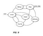
- FIG. 8is a state diagram depicting a stationary detection mechanism according to an exemplary embodiment of the present invention.
- FIG. 9is a block diagram illustrating transformation of sensed motion data from a first frame of reference into a second frame of reference according to an exemplary embodiment of the present invention.
- FIG. 10graphically illustrates the transformation of sensed motion data from a first frame of reference into a second frame of reference according to an exemplary embodiment of the present invention.
- an exemplary aggregated media system 200 in which the present invention can be implementedwill first be described with respect to FIG. 2 .
- I/Oinput/output
- the I/O bus 210represents any of a number of different of mechanisms and techniques for routing signals between the media system components.
- the I/O bus 210may include an appropriate number of independent audio “patch” cables that route audio signals, coaxial cables that route video signals, two-wire serial lines or infrared or radio frequency transceivers that route control signals, optical fiber or any other routing mechanisms that route other types of signals.
- the media system 200includes a television/monitor 212 , a video cassette recorder (VCR) 214 , digital video disk (DVD) recorder/playback device 216 , audio/video tuner 218 and compact disk player 220 coupled to the I/O bus 210 .
- the VCR 214 , DVD 216 and compact disk player 220may be single disk or single cassette devices, or alternatively may be multiple disk or multiple cassette devices. They may be independent units or integrated together.
- the media system 200includes a microphone/speaker system 222 , video camera 224 and a wireless I/O control device 226 .
- the wireless I/O control device 226is a 3D pointing device according to one of the exemplary embodiments described below.
- the wireless I/O control device 226can communicate with the entertainment system 200 using, e.g., an IR or RF transmitter or transceiver.
- the I/O control devicecan be connected to the entertainment system 200 via a wire.
- the entertainment system 200also includes a system controller 228 .
- the system controller 228operates to store and display entertainment system data available from a plurality of entertainment system data sources and to control a wide variety of features associated with each of the system components.
- system controller 228is coupled, either directly or indirectly, to each of the system components, as necessary, through I/O bus 210 .
- system controller 228in addition to or in place of I/O bus 210 , system controller 228 is configured with a wireless communication transmitter (or transceiver), which is capable of communicating with the system components via IR signals or RF signals. Regardless of the control medium, the system controller 228 is configured to control the media components of the media system 200 via a graphical user interface described below.
- media system 200may be configured to receive media items from various media sources and service providers.
- media system 200receives media input from and, optionally, sends information to, any or all of the following sources: cable broadcast 230 , satellite broadcast 232 (e.g., via a satellite dish), very high frequency (VHF) or ultra high frequency (UHF) radio frequency communication of the broadcast television networks 234 (e.g., via an aerial antenna), telephone network 236 and cable modem 238 (or another source of Internet content).
- VHFvery high frequency
- UHFultra high frequency
- remote devices in accordance with the present inventioncan be used in conjunction with other systems, for example computer systems including, e.g., a display, a processor and a memory system or with various other systems and applications.
- remote deviceswhich operate as 3D pointers are of particular interest for the present specification. Such devices enable the translation of movement, e.g., gestures, into commands to a user interface.
- An exemplary 3D pointing device 400is depicted in FIG. 3 .
- user movement of the 3D pointingcan be defined, for example, in terms of a combination of x-axis attitude (roll), y-axis elevation (pitch) and/or z-axis heading (yaw) motion of the 3D pointing device 400 .
- some exemplary embodiments of the present inventioncan also measure linear movement of the 3D pointing device 400 along the x, y, and z axes to generate cursor movement or other user interface commands.
- the 3D pointing device 400includes two buttons 402 and 404 as well as a scroll wheel 406 , although other exemplary embodiments will include other physical configurations. According to exemplary embodiments of the present invention, it is anticipated that 3D pointing devices 400 will be held by a user in front of a display 408 and that motion of the 3D pointing device 400 will be translated by the 3D pointing device into output which is usable to interact with the information displayed on display 408 , e.g., to move the cursor 410 on the display 408 .
- rotation of the 3D pointing device 400 about the y-axiscan be sensed by the 3D pointing device 400 and translated into an output usable by the system to move cursor 410 along the y 2 axis of the display 408 .
- rotation of the 3D pointing device 408 about the z-axiscan be sensed by the 3D pointing device 400 and translated into an output usable by the system to move cursor 410 along the x 2 axis of the display 408 .
- the output of 3D pointing device 400can be used to interact with the display 408 in a number of ways other than (or in addition to) cursor movement, for example it can control cursor fading, volume or media transport (play, pause, fast-forward and rewind).
- Input commandsmay include operations in addition to cursor movement, for example, a zoom in or zoom out on a particular region of a display. A cursor may or may not be visible.
- rotation of the 3D pointing device 400 sensed about the x-axis of 3D pointing device 400can be used in addition to, or as an alternative to, y-axis and/or z-axis rotation to provide input to a user interface.
- two rotational sensors 502 and 504 and one accelerometer 506can be employed as sensors in 3D pointing device 400 as shown in FIG. 4 .
- the rotational sensors 502 and 504can, for example, be implemented using ADXRS150 or ADXRS401 sensors made by Analog Devices. It will be appreciated by those skilled in the art that other types of rotational sensors can be employed as rotational sensors 502 and 504 and that the ADXRS150 and ADXRS401 are purely used as an illustrative example.
- the ADXRS150 rotational sensorsuse MEMS technology to provide a resonating mass which is attached to a frame so that it can resonate only along one direction.
- the resonating massis displaced when the body to which the sensor is affixed is rotated around the sensor's sensing axis. This displacement can be measured using the Coriolis acceleration effect to determine an angular velocity associated with rotation along the sensing axis. If the rotational sensors 502 and 504 have a single sensing axis (as for example the ADXRS150s), then they can be mounted in the 3D pointing device 400 such that their sensing axes are aligned with the rotations to be measured.
- rotational sensor 504is mounted such that its sensing axis is parallel to the y-axis and that rotational sensor 502 is mounted such that its sensing axis is parallel to the z-axis as shown in FIG. 4 .
- aligning the sensing axes of the rotational sensors 502 and 504 parallel to the desired measurement axesis not required since exemplary embodiments of the present invention also provide techniques for compensating for offset between axes.
- One challenge faced in implementing exemplary 3D pointing devices 400 in accordance with the present inventionis to employ components, e.g., rotational sensors 502 and 504 , which are not too costly, while at the same time providing a high degree of correlation between movement of the 3D pointing device 400 , a user's expectation regarding how the user interface will react to that particular movement of the 3D pointing device and actual user interface performance in response to that movement. For example, if the 3D pointing device 400 is not moving, the user will likely expect that the cursor ought not to be drifting across the screen.
- componentse.g., rotational sensors 502 and 504
- various measurements and calculationsare performed by the handheld device 400 which are used to adjust the outputs of one or more of the sensors 502 , 504 and 506 and/or as part of the input used by a processor to determine an appropriate output for the user interface based on the outputs of the sensors 502 , 504 and 506 .
- a process model 600 which describes the general operation of 3D pointing devices according to exemplary embodiments of the present inventionis illustrated in FIG. 5 .
- the rotational sensors 502 and 504 , as well as the accelerometer 506produce analog signals which are sampled periodically, e.g., 200 samples/second.
- a set of these inputsshall be referred to using the notation (x, y, z, ⁇ y, ⁇ z), wherein x, y, z are the sampled output values of the exemplary three-axis accelerometer 506 which are associated with acceleration of the 3D pointing device in the x-axis, y-axis and z-axis directions, respectively, ⁇ y is a the sampled output value from rotational sensor 502 associated with the rotation of the 3D pointing device about the y-axis and ⁇ z is the sampled output value from rotational sensor 504 associated with rotation of the 3D pointing device 400 about the z-axis.
- the output from the accelerometer 506is provided and, if the accelerometer 506 provides analog output, then the output is sampled and digitized by an A/D converter (not shown) to generate sampled accelerometer output 602 .
- the sampled output valuesare converted from raw units to units of acceleration, e.g., gravities (g), as indicated by conversion function 604 .
- the acceleration calibration block 606provides the values used for the conversion function 604 .
- This calibration of the accelerometer output 602can include, for example, compensation for one or more of scale, offset and axis misalignment error associated with the accelerometer 506 .
- the exemplary accelerometer 506has an exemplary full range of +/ ⁇ 2 g.
- Sensor offset, Prefers to the sensor output, M, for an accelerometer measurement of 0 g.
- Scalerefers to the conversion factor between the sampled unit value and g.
- the actual scale of any given accelerometer sensormay deviate from these nominal scale values due to, e.g., manufacturing variances. Accordingly the scale factor in the equations above will be proportional to this deviation.
- Accelerometer 506 scale and offset deviationscan be measured by, for example, applying 1 g of force along one an axis and measuring the result, R1. Then a ⁇ 1 g force is applied resulting in measurement R2.
- readings generated by accelerometer 506may also suffer from cross-axes effects.
- Cross-axes effectsinclude non-aligned axes, e.g., wherein one or more of the sensing axes of the accelerometer 506 as it is mounted in the 3D pointing device 400 are not aligned with the corresponding axis in the inertial frame of reference, or mechanical errors associated with the machining of the accelerometer 506 itself, e.g., wherein even though the axes are properly aligned, a purely y-axis acceleration force may result in a sensor reading along the z-axis of the accelerometer 506 . Both of these effects can also be measured and added to the calibration performed by function 606 .
- the accelerometer 506serves several purposes in exemplary 3D pointing devices according to exemplary embodiments of the present invention. For example, if rotational sensors 502 and 504 are implemented using the exemplary Coriolis effect rotational sensors described above, then the output of the rotational sensors 502 and 504 will vary based on the linear acceleration experienced by each rotational sensor. Thus, one exemplary use of the accelerometer 506 is to compensate for fluctuations in the readings generated by the rotational sensors 502 and 504 which are caused by variances in linear acceleration. This can be accomplished by multiplying the converted accelerometer readings by a gain matrix 610 and subtracting (or adding) the results from (or to) the corresponding sampled rotational sensor data 612 .
- linear acceleration compensation for the sampled rotational data ⁇ z from rotational sensor 504can be provided at block 614 .
- the gain matrices, Cvary between rotational sensors due to manufacturing differences. C may be computed using the average value for many rotational sensors, or it may be custom computed for each rotational sensor.
- the sampled rotational data 612is then converted from a sampled unit value into a value associated with a rate of angular rotation, e.g., radians/s, at function 616 .
- This conversion stepcan also include calibration provided by function 618 to compensate the sampled rotational data for, e.g., scale and offset.
- Equation (5)may be implemented as a matrix equation in which case all variables are vectors except for scale. In matrix equation form, scale corrects for axis misalignment and rotational offset factors. Each of these variables is discussed in more detail below.
- the offset values offset(T) and dOffsetcan be determined in a number of different ways.
- the sensor 502should output its offset value.
- the offsetcan be highly affected by temperature, so this offset value will likely vary.
- Offset temperature calibrationmay be performed at the factory, in which case the value(s) for offset(T) can be preprogrammed into the handheld device 400 or, alternatively, offset temperature calibration may also be learned dynamically during the lifetime of the device.
- an input from a temperature sensor 619is used in rotation calibration function 618 to compute the current value for offset(T).
- the offset(T) parameterremoves the majority of offset bias from the sensor readings.
- the stationary detection function 608determines when the handheld is most likely stationary and when the offset should be recomputed. Exemplary techniques for implementing stationary detection function 608 , as well as other uses therefore, are described below.
- dOffset computationemploys calibrated sensor outputs which are low-pass filtered.
- the stationary output detection function 608provides an indication to rotation calibration function 618 to trigger computation of, for example, the mean of the low-pass filter output.
- the stationary output detection function 608can also control when the newly computed mean is factored into the existing value for dOffset.
- a multitude of different techniquescan be used for computing the new value for dOffset from the existing value of dOffset and the new mean including, but not limited to, simple averaging, low-pass filtering and Kalman filtering.
- numerous variations for offset compensation of the rotational sensors 502 and 504can be employed.
- the offset(T) functioncan have a constant value (e.g., invariant with temperature), more than two offset compensation values can be used and/or only a single offset value can be computed/used for offset compensation.
- the inputs from the rotational sensors 502 and 504can be further processed to rotate those inputs into an inertial frame of reference, i.e., to compensate for tilt associated with the manner in which the user is holding the 3D pointing device 400 , at function 620 .
- Tilt correctionis another significant aspect of some exemplary embodiments of the present invention as it is intended to compensate for differences in usage patterns of 3D pointing devices according to the present invention. More specifically, tilt correction according to exemplary embodiments of the present invention is intended to compensate for the fact that users will hold pointing devices in their hands at different x-axis rotational positions, but that the sensing axes of the rotational sensors 502 and 504 in the 3D pointing devices 400 are fixed.
- cursor translation across display 408is substantially insensitive to the way in which the user grips the 3D pointing device 400 , e.g., rotating the 3D pointing device 400 back and forth in a manner generally corresponding to the horizontal dimension (x 2 -axis) of the display 508 should result in cursor translation along the x 2 -axis, while rotating the 3D pointing device up and down in a manner generally corresponding to the vertical dimension (y 2 -axis) of the display 508 should result in cursor translation along the y 2 -axis, regardless of the orientation in which the user is holding the 3D pointing device 400 .
- the useris holding 3D pointing device 400 in an exemplary inertial frame of reference, which can be defined as having an x-axis rotational value of 0 degrees, e.g., the inertial frame of reference can that in which the 3D device has its bottom substantially parallel to a floor of a room in which, e.g., a television is located.
- the inertial frame of referencecan, purely as an example, correspond to the orientation illustrated in FIG. 6( a ) or it can be defined as any other orientation.
- Rotation of the 3D pointing device 400 in either the y-axis or z-axis directionswill be sensed by rotational sensors 502 and 504 , respectively.
- rotational sensors 502 and 504For example, rotation of the 3D pointing device 400 around the z-axis by an amount ⁇ z as shown in FIG. 6( b ) will result in a corresponding cursor translation ⁇ x 2 in the x 2 axis dimension across the display 408 (i.e., the distance between the dotted version of cursor 410 and the undotted version).
- the information provided by the sensors 502 and 504would not (absent tilt compensation) provide an accurate representation of the user's intended interface actions.
- FIG. 6( c )consider a situation wherein the user holds the 3D pointing device 400 with an x-axis rotation of 45 degrees relative to the exemplary inertial frame of reference as illustrated in FIG. 6( a ). Assuming the same z-axis rotation ⁇ z is imparted to the 3D pointing device 400 by a user as in the example of FIG.
- the cursor 410will instead be translated in both the x 2 -axis direction and the y 2 -axis direction as shown in FIG. 6( d ).
- the sensing axis of the rotational sensor 504is also oriented between the y-axis and the z-axis (although in a different quadrant).
- tilt compensationIn order to provide an interface which is transparent to the user in terms of how the 3D pointing device 400 is held, tilt compensation according to exemplary embodiments of the present invention translates the readings output from rotational sensors 502 and 504 back into the inertial frame of reference as part of processing the readings from these sensors into information indicative of rotational motion of the 3D pointing device 400 .
- thiscan be accomplished by determining the tilt of the 3D pointing device 400 using the inputs y and z received from accelerometer 506 at function 622 . More specifically, after the acceleration data is converted and calibrated as described above, it can be low pass filtered at LPF 624 to provide an average acceleration (gravity) value to the tilt determination function 622 . Then, tilt ⁇ can be calculated in function 622 as:
- ⁇tan - 1 ⁇ ( y z ) ( 7 )
- the value ⁇can be numerically computed as atan 2(y,z) to prevent division by zero and give the correct sign.
- function 620can perform the rotation R of the converted/calibrated inputs ⁇ y and ⁇ z using the equation:
- Tilt compensationas described in this exemplary embodiment is a subset of a more general technique for translating sensor readings from the body frame of reference into a user's frame of reference according to another exemplary embodiment of the present invention which is described below.
- post-processingcan be performed at blocks 626 and 628 .
- Exemplary post-processingcan include compensation for various factors such as human tremor.
- tremormay be removed using several different methods, one way to remove tremor is by using hysteresis.
- the angular velocity produced by rotation function 620is integrated to produce an angular position.
- Hysteresis of a calibrated magnitudeis then applied to the angular position.
- the derivativeis taken of the output of the hysteresis block to again yield an angular velocity.
- the resulting outputis then scaled at function 628 (e.g., based on the sampling period) and used to generate a result within the interface, e.g., movement of a cursor 410 on a display 408 .
- FIG. 7illustrates an exemplary hardware architecture.
- a processor 800communicates with other elements of the 3D pointing device including a scroll wheel 802 , JTAG 804 , LEDs 806 , switch matrix 808 , IR photodetector 810 , rotational sensors 812 , accelerometer 814 and transceiver 816 .
- the scroll wheel 802is an optional input component which enables a user to provide input to the interface by rotating the scroll wheel 802 clockwise or counterclockwise.
- JTAG 804provides the programming and debugging interface to the processor.
- LEDs 806provide visual feedback to a user, for example, when a button is pressed.
- Switch matrix 808receives inputs, e.g., indications that a button on the 3D pointing device 400 has been depressed or released, that are then passed on to processor 800 .
- the optional IR photodetector 810can be provided to enable the exemplary 3D pointing device to learn IR codes from other remote controls.
- Rotational sensors 812provide readings to processor 800 regarding, e.g., the y-axis and z-axis rotation of the 3D pointing device as described above.
- Accelerometer 814provides readings to processor 800 regarding the linear acceleration of the 3D pointing device 400 which can be used as described above, e.g., to perform tilt compensation and to compensate for errors which linear acceleration introduces into the rotational readings generated by rotational sensors 812 .
- Transceiver 816is used to communicate information to and from 3D pointing device 400 , e.g., to the system controller 228 or to a processor associated with a computer.
- the transceiver 816can be a wireless transceiver, e.g., operating in accordance with the Bluetooth standards for short-range wireless communication or an infrared transceiver.
- 3D pointing device 400can communicate with systems via a wireline connection.
- the 3D pointing device 400includes two rotational sensors 502 and 504 , as well as an accelerometer 506 .
- a 3D pointing devicecan alternatively include just one rotational sensor, e.g., for measuring angular velocity in the z-axis direction, and an accelerometer.
- similar functionality to that described abovecan be provided by using the accelerometer to determine the angular velocity along the axis which is not sensed by the rotational sensor.
- rotational velocity around the y-axiscan be computed using data generated by the accelerometer and calculating:
- parasitic acceleration effectsthat are not measured by a rotational sensor should also be removed. These effects include actual linear acceleration, acceleration measured due to rotational velocity and rotational acceleration, and acceleration due to human tremor.
- Stationary detection function 608can operate to determine whether the 3D pointing device 400 is, for example, either stationary or active (moving). This categorization can be performed in a number of different ways.
- One way, according to an exemplary embodiment of the present invention,is to compute the variance of the sampled input data of all inputs (x, y, z, ⁇ y, ⁇ z) over a predetermined window, e.g., every quarter of a second. This variance is then compared with a threshold to classify the 3D pointing device as either stationary or active.
- Another stationary detection techniqueinvolves transforming the inputs into the frequency domain by, e.g., performing a Fast Fourier Transform (FFT) on the input data. Then, the data can be analyzed using, e.g., peak detection methods, to determine if the 3D pointing device 400 is either stationary or active. Additionally, a third category can be distinguished, specifically the case where a user is holding the 3D pointing device 400 but is not moving it (also referred to herein as the “stable” state. This third category can be distinguished from stationary (not held) and active by detecting the small movement of the 3D pointing device 400 introduced by a user's hand tremor when the 3D pointing device 400 is being held by a user.
- FFTFast Fourier Transform
- Peak detectioncan also be used by stationary detection function 608 to make this determination. Peaks within the range of human tremor frequencies, e.g., nominally 8-12 Hz, will typically exceed the noise floor of the device (experienced when the device is stationary and not held) by approximately 20 dB.
- the variances in the frequency domainwere sensed within a particular frequency range, however the actual frequency range to be monitored and used to characterize the status of the 3D pointing device 400 may vary.
- the nominal tremor frequency rangemay shift based on e.g., the ergonomics and weight of the 3D pointing device 400 , e.g., from 8-12 Hz to 4-7 Hz.
- stationary detection mechanism 608can include a state machine.
- An exemplary state machineis shown in FIG. 8 .
- the ACTIVE stateis, in this example, the default state during which the 3D pointing device 400 is moving and being used to, e.g., provide inputs to a user interface.
- the 3D pointing device 400can enter the ACTIVE state on power-up of the device as indicated by the reset input. If the 3D pointing device 400 stops moving, it may then enter the INACTIVE state.
- condition active ⁇ inactivecan, in an exemplary 3D pointing device 400 , occur when mean and/or standard deviation values from both the rotational sensor(s) and the accelerometer fall below first predetermined threshold values for a first predetermined time period.
- State transitionscan be determined by a number of different conditions based upon the interpreted sensor outputs.
- Exemplary condition metricsinclude the variance of the interpreted signals over a time window, the threshold between a reference value and the interpreted signal over a time window, the threshold between a reference value and the filtered interpreted signal over a time window, and the threshold between a reference value and the interpreted signal from a start time can be used to determine state transitions. All, or any combination, of these condition metrics can be used to trigger state transitions. Alternatively, other metrics can also be used.
- a transition from the INACTIVE state to the ACTIVE stateoccurs either when (1) a mean value of sensor output(s) over a time window is greater than predetermined threshold(s) or (2) a variance of values of sensor output(s) over a time window is greater than predetermined threshold(s) or (3) an instantaneous delta between sensor values is greater than a predetermined threshold.
- the INACTIVE stateenables the stationary detection mechanism 608 to distinguish between brief pauses during which the 3D pointing device 400 is still being used, e.g., on the order of a tenth of a second, and an actual transition to either a stable or stationary condition. This protects against the functions which are performed during the STABLE and STATIONARY states, described below, from inadvertently being performed when the 3D pointing device is being used.
- the 3D pointing device 400will transition back to the ACTIVE state when condition inactive ⁇ active occurs, e.g., if the 3D pointing device 400 starts moving again such that the measured outputs from the rotational sensor(s) and the accelerometer exceeds the first threshold before a second predetermined time period in the INACTIVE state elapses.
- the 3D pointing device 400will transition to either the STABLE state or the STATIONARY state after the second predetermined time period elapses.
- the STABLE statereflects the characterization of the 3D pointing device 400 as being held by a person but being substantially unmoving
- the STATIONARY statereflects a characterization of the 3D pointing device as not being held by a person.
- an exemplary state machine according to the present inventioncan provide for a transition to the STABLE state after the second predetermined time period has elapsed if minimal movement associated with hand tremor is present or, otherwise, transition to the STATIONARY state.
- the STABLE and STATIONARY statesdefine times during which the 3D pointing device 400 can perform various functions. For example, since the STABLE state is intended to reflect times when the user is holding the 3D pointing device 400 but is not moving it, the device can record the movement of the 3D pointing device 400 when it is in the STABLE state e.g., by storing outputs from the rotational sensor(s) and/or the accelerometer while in this state. These stored measurements can be used to determine a tremor pattern associated with a particular user or users as described below. Likewise, when in the STATIONARY state, the 3D pointing device 400 can take readings from the rotational sensors and/or the accelerometer for use in compensating for offset as described above.
- the device 400can transition to the SLEEP state. While in the sleep state, the device can enter a power down mode wherein power consumption of the 3D pointing device is reduced and, e.g., the sampling rate of the rotational sensors and/or the accelerometer is also reduced.
- the SLEEP statecan also be entered via an external command so that the user or another device can command the 3D pointing device 400 to enter the SLEEP state.
- the devicecan transition from the SLEEP state to the WAKEUP state.
- the WAKEUP stateprovides an opportunity for the device to confirm that a transition to the ACTIVE state is justified, e.g., that the 3D pointing device 400 was not inadvertently jostled.
- the conditions for state transitionsmay be symmetrical or may differ.
- the threshold associated with the condition active ⁇ inactivemay be the same as (or different from) the threshold(s) associated with the condition inactive ⁇ active .
- Thisenables 3D pointing devices according to the present invention to more accurately capture user input.
- exemplary embodiments which include a state machine implementationallow, among other things, for the threshold for transition into a stationary condition to be different than the threshold for the transition out of a stationary condition.
- Entering or leaving a statecan be used to trigger other device functions as well.
- the user interfacecan be powered up based on a transition from any state to the ACTIVE state.
- the 3D pointing device and/or the user interfacecan be turned off (or enter a sleep mode) when the 3D pointing device transitions from ACTIVE or STABLE to STATIONARY or INACTIVE.
- the cursor 410can be displayed or removed from the screen based on the transition from or to the stationary state of the 3D pointing device 400 .
- exemplary embodiments of the present inventionprocess movement data received from sensor(s) in the 3D pointing device to convert this data from the frame of reference of the 3D pointing device's body into another frame of reference, e.g., the user's frame of reference.
- the user's frame of referencemight be a coordinate system associated with the television screen.
- translation of the data from the body frame of reference into another frame of referenceimproves the usability of the handheld device by resulting in an operation that is from the user's perspective rather than the device's perspective.
- the cursorwill move in the left to right direction regardless of the orientation of the 3D pointing device.
- the handheld systemsenses motion using one or more sensors 901 , e.g., rotational sensor(s), gyroscopes(s), accelerometer(s), magnetometer(s), optical sensor(s), camera(s) or any combination thereof.
- the sensorsare then interpreted in block 902 to produce an estimate of the motion that occurred.
- the processing block 903then translates the measured motion from the natural (body) reference frame of the device into the reference frame of the user.
- the movementis then mapped 904 into meaningful actions that are interpreted at block 905 forwarded to the system to produce a meaningful response, such as moving an on-screen cursor.
- Block 903converts detected movement into the reference frame of the user instead of the reference frame of the device.
- Orientationmay be represented by many different mathematically similar methods including Euler angles, a direction cosine matrix (DCM), or a unit quaternion.
- Positionis generally represented as an offset from the coordinate system origin in a consistent unit including but not limited to meters, centimeters, feet, inches, and miles.
- a 3D pointing devicemeasures inertial forces including acceleration and rotational velocity. These forces are measured relative to the body of the device by sensors mounted therein. In order to convert the measured data into the user frame of reference, the device estimates both its position and its orientation.
- the user frame of referenceis stationary and has fixed orientation, although those skilled in the art will appreciate that this technique in accordance with the present invention can be readily extended to the cases where the user's frame of reference is non-stationary by either directly transforming to the time-varying frame or by first converting to a stationary frame and then converting to the moving frame.
- Rotaterepresents the quaternion rotation operator such that Rotate(A, Q) is equal to Q*A Q where Q* is the quaternion conjugate and the vector A is a quaternion with the complex component equal to A and the real component equal to 0;
- Puis the position in the user frame of reference
- Pbis the position in the device frame of reference
- Pu′is the derivative of the position in the user frame of reference which is the velocity in the user frame of reference;
- Wuis the angular velocity of the device in body angles in the user frame of reference
- Wbis the angular velocity of the device in body angles in the body frame of the device
- Pdeltais the difference between the origin of the user frame of reference and the body frame of reference in the user frame of reference coordinate system
- Qis the normalized rotation quaternion that represents the rotation from the body frame to the user frame. Since the rotation quaternion to rotate from the user frame to the body frame is Q*, we could replace Q with R* where R is the rotation from the user frame to the body frame.
- Qcan be represented in a number of equivalent forms including Euler angles and the direction cosine matrix (DCM), and the above equations may vary slightly in their equivalent forms based upon different representations of Q.
- FIG. 10graphically illustrates the transformation from a body frame of reference to a user's frame of reference.
- the deviceestimates Q in an implementation dependent manner to perform this transformation.
- One exemplary implementation described aboveinvolves compensating for tilt (i.e., variations in x-axis roll of the 3D pointing device based on the manner in which it is held by a user).
- the orientationis computed by first estimating the acceleration component due to gravity in the body frame, Ab.
- Pu′, Pu′′, Wu, and Wu′′are all 0.
- Pb′′ and Wbare measured.
- sensorscould be employed as long as they measure motion with respect to the body of the device.
- exemplary sensorsinclude accelerometers, rotational sensors, gyroscopes, magnetometers and cameras.
- the user framedoes not need to be stationary. For example, if the user's frame of reference is selected to be the user's forearm, then the device would only respond to wrist and finger movement.
- frame of reference transformationscan also be used to address other challenges in handheld device implementations.
- a sensorsuch as an accelerometer
- R⁇ ⁇ ⁇ ⁇ ⁇ ⁇ ⁇ ⁇ ⁇ ⁇ ⁇ ⁇ ⁇ ⁇ ⁇ ⁇ ⁇ ⁇ ⁇ ⁇ ⁇ ⁇ ⁇ ⁇ ⁇ ⁇ ⁇ ⁇ ⁇ ⁇ ⁇ ⁇ ⁇ ⁇ ⁇ ⁇ ⁇ ⁇ ⁇ ⁇ ⁇ ⁇ ⁇ ⁇ ⁇ ⁇ ⁇ ⁇ ⁇ ⁇ ⁇ ⁇ ⁇ ⁇ ⁇ ⁇ Rotate[Ag, Q]. Note that many numerical methods exist including recursive least squares and Kalman filtering that may perform minimization to compute Rx.
- the present inventiondescribes various techniques for mapping sensed motion of a handheld device from one frame of reference (e.g., a body frame of reference) to another frame of reference (e.g., a user's frame of reference). These mappings can be independent from other mappings associated with the use of the handheld device, e.g., the mapping of sensed motion to cursor movement or can be combined therewith. Moreover, transformations according to the present invention can be performed to transform the sensed motion in all three dimensions, for translational motion and rotational motion or any subset thereof, from the perspective of either the input side of the motion equation or the output side.
- the selection of the frame of reference into which the sensed motion is mapped or transformedcan be made in a number of different ways.
- the second frame of referencebeing a user's frame of reference associated with the tilt of the device, however many other variations are possible.
- the usermay select his or her desired frame of reference, which setting can be stored in the handheld as one of a plurality of user preferences and used to perform the transformation.
- the second frame of referencecan be selected based on any number of techniques.
- the second frame of referencecan be selected based upon an explicit command (e.g., button or user interface selection) or automatically through user recognition determined by device use patterns, tremor, and other biometrics.
- mapping or transformation according to the present inventioncan alternatively or additionally be performed on, for example, position or acceleration data and can be for translational motion, rotational motion or both. Also the order of processing is not critical. For example, if the handheld device is being used to output gesture commands, the mapping can be performed first and then the gesture determined or the gesture can be determined first and then the mapping can be performed.
Landscapes
- Engineering & Computer Science (AREA)
- General Engineering & Computer Science (AREA)
- Theoretical Computer Science (AREA)
- Human Computer Interaction (AREA)
- Physics & Mathematics (AREA)
- General Physics & Mathematics (AREA)
- Multimedia (AREA)
- Signal Processing (AREA)
- Position Input By Displaying (AREA)
Abstract
Description
A=S*((M−P).*G(T)) (1)
wherein M is a 3×1 column vector composed of the sampled output values (x, y, z), P is a 3×1 column vector of sensor offsets, and S is a 3×3 matrix that contains both scale, axis misalignment, and sensor rotation compensation. G(T) is a gain factor that is a function of temperature. The “*” operator represents matrix multiplication and the “.*” operator represents element multiplication. The
s=(R1−R2)/2 (2)
p=(R1+R2)/2 (3)
In this simple case, P is the column vector of the p for each axis, and S is the diagonal matrix of the 1/s for each axis.
αy′=αy−C*A (4)
wherein C is the 1×3 row vector of rotational sensor susceptibility to linear acceleration along each axis given in units/g and A is the calibrated linear acceleration. Similarly, linear acceleration compensation for the sampled rotational data αz from
αrad/s=(α′−offset(T))*scale+dOffset (5)
wherein α′ refers to the value being converted/calibrated, offset(T) refers to an offset value associated with temperature, scale refers to the conversion factor between the sampled unit value and rad/s, and dOffset refers to a dynamic offset value. Equation (5) may be implemented as a matrix equation in which case all variables are vectors except for scale. In matrix equation form, scale corrects for axis misalignment and rotational offset factors. Each of these variables is discussed in more detail below.
The value θ can be numerically computed as atan 2(y,z) to prevent division by zero and give the correct sign. Then, function620 can perform the rotation R of the converted/calibrated inputs αy and αz using the equation:
to rotate the converted/calibrated inputs αy and αz to compensate for the tilt θ. Tilt compensation as described in this exemplary embodiment is a subset of a more general technique for translating sensor readings from the body frame of reference into a user's frame of reference according to another exemplary embodiment of the present invention which is described below.
In addition, the parasitic acceleration effects that are not measured by a rotational sensor should also be removed. These effects include actual linear acceleration, acceleration measured due to rotational velocity and rotational acceleration, and acceleration due to human tremor.
Pu=Rotate(Pb,Q)+Pdelta
Pu′=Rotate(Pb′,Q)
Pu″=Rotate(Pb″,Q)
Wu=Rotate(Wb,Q)
Wu′=Rotate(Wb′,Q)
where:
V=∥Ab∥×∥Ag∥(cross product of unit vectors)
qV=∥V∥
α=sin−1|V|
Q=Quaternion[qV,α]=[qV*sin(α/2), cos(α/2)]
Position is then computed as the double integral of the acceleration in the user frame. The acceleration in the user frame is the acceleration of the body frame rotated into the user frame by Q above. Normally, the origin is assumed to be zero when the device is first activated, but the origin may be reset during normal operation either manually or automatically.
WbAngle=|Wb∥*period
QDELTA=Quaternion[Wb,WbAngle]=[∥Wb∥*sin(WbAngle/2), cos(WbAngle/2)]
QNEXT=Q0**QDELTA
Abody=Aaccelerometer+ω′×R+ω×(ω×R)
where R is the vector from the accelerometer to the target location, ω is the angular velocity of the body frame of reference and ω′ is the angular acceleration of the body frame of reference. If the body frame of the device is constructed such that it lies at R from the accelerometer, then it should have zero angular acceleration effects and may be more easily used to compute the device movement in the user frame. This compensates for intentional or unintentional misalignment between the accelerometer and the center of the body frame of reference. In addition, the estimate of the gravity vector becomes much simpler since there are fewer forces acting at the center of rotation. Then,
Auser=Rotate(Abody,Q)
where Q is the rotation from the body frame of reference to the accelerometer frame of reference.
Claims (18)
Priority Applications (4)
| Application Number | Priority Date | Filing Date | Title |
|---|---|---|---|
| US14/090,050US8937594B2 (en) | 2004-04-30 | 2013-11-26 | 3D pointing devices with orientation compensation and improved usability |
| US14/563,314US9298282B2 (en) | 2004-04-30 | 2014-12-08 | 3D pointing devices with orientation compensation and improved usability |
| US15/015,745US9946356B2 (en) | 2004-04-30 | 2016-02-04 | 3D pointing devices with orientation compensation and improved usability |
| US15/941,034US10782792B2 (en) | 2004-04-30 | 2018-03-30 | 3D pointing devices with orientation compensation and improved usability |
Applications Claiming Priority (9)
| Application Number | Priority Date | Filing Date | Title |
|---|---|---|---|
| US56644404P | 2004-04-30 | 2004-04-30 | |
| US61257104P | 2004-09-23 | 2004-09-23 | |
| US64141005P | 2005-01-05 | 2005-01-05 | |
| US11/119,719US7158118B2 (en) | 2004-04-30 | 2005-05-02 | 3D pointing devices with orientation compensation and improved usability |
| US11/640,677US7262760B2 (en) | 2004-04-30 | 2006-12-18 | 3D pointing devices with orientation compensation and improved usability |
| US11/820,517US7414611B2 (en) | 2004-04-30 | 2007-06-20 | 3D pointing devices with orientation compensation and improved usability |
| US12/188,595US8072424B2 (en) | 2004-04-30 | 2008-08-08 | 3D pointing devices with orientation compensation and improved usability |
| US13/304,854US8629836B2 (en) | 2004-04-30 | 2011-11-28 | 3D pointing devices with orientation compensation and improved usability |
| US14/090,050US8937594B2 (en) | 2004-04-30 | 2013-11-26 | 3D pointing devices with orientation compensation and improved usability |
Related Parent Applications (1)
| Application Number | Title | Priority Date | Filing Date |
|---|---|---|---|
| US13/304,854ContinuationUS8629836B2 (en) | 2004-04-30 | 2011-11-28 | 3D pointing devices with orientation compensation and improved usability |
Related Child Applications (1)
| Application Number | Title | Priority Date | Filing Date |
|---|---|---|---|
| US14/563,314ContinuationUS9298282B2 (en) | 2004-04-30 | 2014-12-08 | 3D pointing devices with orientation compensation and improved usability |
Publications (2)
| Publication Number | Publication Date |
|---|---|
| US20140078059A1 US20140078059A1 (en) | 2014-03-20 |
| US8937594B2true US8937594B2 (en) | 2015-01-20 |
Family
ID=38660774
Family Applications (5)
| Application Number | Title | Priority Date | Filing Date |
|---|---|---|---|
| US13/304,854Expired - LifetimeUS8629836B2 (en) | 2004-04-30 | 2011-11-28 | 3D pointing devices with orientation compensation and improved usability |
| US14/090,050Expired - LifetimeUS8937594B2 (en) | 2004-04-30 | 2013-11-26 | 3D pointing devices with orientation compensation and improved usability |
| US14/563,314Expired - LifetimeUS9298282B2 (en) | 2004-04-30 | 2014-12-08 | 3D pointing devices with orientation compensation and improved usability |
| US15/015,745Expired - LifetimeUS9946356B2 (en) | 2004-04-30 | 2016-02-04 | 3D pointing devices with orientation compensation and improved usability |
| US15/941,034Expired - LifetimeUS10782792B2 (en) | 2004-04-30 | 2018-03-30 | 3D pointing devices with orientation compensation and improved usability |
Family Applications Before (1)
| Application Number | Title | Priority Date | Filing Date |
|---|---|---|---|
| US13/304,854Expired - LifetimeUS8629836B2 (en) | 2004-04-30 | 2011-11-28 | 3D pointing devices with orientation compensation and improved usability |
Family Applications After (3)
| Application Number | Title | Priority Date | Filing Date |
|---|---|---|---|
| US14/563,314Expired - LifetimeUS9298282B2 (en) | 2004-04-30 | 2014-12-08 | 3D pointing devices with orientation compensation and improved usability |
| US15/015,745Expired - LifetimeUS9946356B2 (en) | 2004-04-30 | 2016-02-04 | 3D pointing devices with orientation compensation and improved usability |
| US15/941,034Expired - LifetimeUS10782792B2 (en) | 2004-04-30 | 2018-03-30 | 3D pointing devices with orientation compensation and improved usability |
Country Status (1)
| Country | Link |
|---|---|
| US (5) | US8629836B2 (en) |
Cited By (5)
| Publication number | Priority date | Publication date | Assignee | Title |
|---|---|---|---|---|
| US20150091800A1 (en)* | 2004-04-30 | 2015-04-02 | Hillcrest Laboratories, Inc. | 3d pointing devices with orientation compensation and improved usability |
| US9575570B2 (en) | 2004-04-30 | 2017-02-21 | Hillcrest Laboratories, Inc. | 3D pointing devices and methods |
| US10159897B2 (en) | 2004-11-23 | 2018-12-25 | Idhl Holdings, Inc. | Semantic gaming and application transformation |
| US12123654B2 (en) | 2010-05-04 | 2024-10-22 | Fractal Heatsink Technologies LLC | System and method for maintaining efficiency of a fractal heat sink |
| US12251201B2 (en) | 2019-08-16 | 2025-03-18 | Poltorak Technologies Llc | Device and method for medical diagnostics |
Families Citing this family (19)
| Publication number | Priority date | Publication date | Assignee | Title |
|---|---|---|---|---|
| US9128981B1 (en) | 2008-07-29 | 2015-09-08 | James L. Geer | Phone assisted ‘photographic memory’ |
| US8775454B2 (en) | 2008-07-29 | 2014-07-08 | James L. Geer | Phone assisted ‘photographic memory’ |
| US9081810B1 (en)* | 2011-04-29 | 2015-07-14 | Google Inc. | Remote device control using gestures on a touch sensitive device |
| US9483117B2 (en)* | 2013-04-08 | 2016-11-01 | Nokia Technologies Oy | Apparatus, method and computer program for controlling a near-eye display |
| WO2014179449A1 (en)* | 2013-05-01 | 2014-11-06 | Hillcrest Laboratories, Inc. | Mapped variable smoothing evolution method and device |
| US9582078B1 (en)* | 2013-06-28 | 2017-02-28 | Maxim Integrated Products, Inc. | Integrated touchless joystick-type controller |
| CN104252228B (en)* | 2013-06-28 | 2019-08-23 | 三星电子株式会社 | Display device and the method for controlling display device |
| EP3054693B1 (en) | 2013-10-02 | 2019-12-25 | Samsung Electronics Co., Ltd | Image display apparatus and pointing method for same |
| CN105808182B (en) | 2015-01-15 | 2019-09-17 | 财团法人工业技术研究院 | Display control method and system, advertisement breach judging device and video and audio processing device |
| CN107532907A (en) | 2015-03-13 | 2018-01-02 | 桑男 | Posture detection equipment |
| US9607428B2 (en) | 2015-06-30 | 2017-03-28 | Ariadne's Thread (Usa), Inc. | Variable resolution virtual reality display system |
| US10089790B2 (en) | 2015-06-30 | 2018-10-02 | Ariadne's Thread (Usa), Inc. | Predictive virtual reality display system with post rendering correction |
| US9588593B2 (en) | 2015-06-30 | 2017-03-07 | Ariadne's Thread (Usa), Inc. | Virtual reality system with control command gestures |
| US9588598B2 (en)* | 2015-06-30 | 2017-03-07 | Ariadne's Thread (Usa), Inc. | Efficient orientation estimation system using magnetic, angular rate, and gravity sensors |
| US10118696B1 (en) | 2016-03-31 | 2018-11-06 | Steven M. Hoffberg | Steerable rotating projectile |
| US10788934B2 (en) | 2017-05-14 | 2020-09-29 | Microsoft Technology Licensing, Llc | Input adjustment |
| US11262854B2 (en)* | 2017-09-25 | 2022-03-01 | Hewlett-Packard Development Company, L.P. | Sensing movement of a hand-held controller |
| US11712637B1 (en) | 2018-03-23 | 2023-08-01 | Steven M. Hoffberg | Steerable disk or ball |
| US10955941B2 (en) | 2019-03-26 | 2021-03-23 | Atlantic Health System, Inc. | Multimodal input device and system for wireless record keeping in a multi-user environment |
Citations (236)
| Publication number | Priority date | Publication date | Assignee | Title |
|---|---|---|---|---|
| GB591019A (en) | 1945-04-13 | 1947-08-05 | Charles Stanley Hudson | Improvements in or relating to remote indicating compasses |
| US3474241A (en) | 1966-10-06 | 1969-10-21 | Jack Kuipers | Coordinate transformer |
| US3660648A (en) | 1969-10-15 | 1972-05-02 | Northrop Corp | Angular rate coordinate transformer |
| US3931747A (en) | 1974-02-06 | 1976-01-13 | Sperry Rand Corporation | Gyroscopic stable reference device |
| US4038876A (en) | 1976-03-04 | 1977-08-02 | Systron Donner Corporation | Acceleration error compensated attitude sensing and control apparatus and method |
| US4402250A (en) | 1979-06-29 | 1983-09-06 | Hollandse Signaalapparaten B.V. | Automatic correction of aiming in firing at moving targets |
| US4558313A (en) | 1981-12-31 | 1985-12-10 | International Business Machines Corporation | Indicator to data processing interface |
| US4558604A (en) | 1981-02-02 | 1985-12-17 | Teldix Gmbh | Directional gyro |
| US4578674A (en) | 1983-04-20 | 1986-03-25 | International Business Machines Corporation | Method and apparatus for wireless cursor position control |
| US4617634A (en) | 1983-06-28 | 1986-10-14 | Mitsubishi Denki Kabushiki Kaisha | Artificial satellite attitude control system |
| US4623930A (en) | 1983-12-29 | 1986-11-18 | Matsushita Electric Industrial Co., Ltd. | Camera apparatus |
| US4686772A (en) | 1986-05-23 | 1987-08-18 | Elbit Computers Ltd. | Electronic magnetic compass system |
| US4718078A (en) | 1985-08-19 | 1988-01-05 | Siemens Aktiengesellschaft | System for controlling motion of a robot |
| US4787051A (en) | 1986-05-16 | 1988-11-22 | Tektronix, Inc. | Inertial mouse system |
| US4839838A (en) | 1987-03-30 | 1989-06-13 | Labiche Mitchell | Spatial input apparatus |
| US4906907A (en) | 1987-03-30 | 1990-03-06 | Hitachi, Ltd. | Robot system |
| US4961369A (en) | 1983-01-21 | 1990-10-09 | The Secretary Of State For Defence In Her Britannic Majesty's Government Of The United Kingdom Of Great Britain And Northern Ireland | Gun laying |
| US5045843A (en) | 1988-12-06 | 1991-09-03 | Selectech, Ltd. | Optical pointing device |
| JPH03204844A (en) | 1989-04-11 | 1991-09-06 | W R Grace & Co | Recovery of glycine and glauber's salt from waste crystal liquid |
| JPH0359619B2 (en) | 1986-08-06 | 1991-09-11 | Kazuo Hashimoto | |
| US5060175A (en) | 1989-02-13 | 1991-10-22 | Hughes Aircraft Company | Measurement and control system for scanning sensors |
| US5128671A (en) | 1990-04-12 | 1992-07-07 | Ltv Aerospace And Defense Company | Control device having multiple degrees of freedom |
| US5138154A (en) | 1990-04-04 | 1992-08-11 | Gyration Inc. | Shaft angle encoder with rotating off-axis interference pattern |
| US5181181A (en) | 1990-09-27 | 1993-01-19 | Triton Technologies, Inc. | Computer apparatus input device for three-dimensional information |
| US5280744A (en) | 1992-01-27 | 1994-01-25 | Alliedsignal Inc. | Method for aiming towed field artillery pieces |
| US5327161A (en) | 1989-08-09 | 1994-07-05 | Microtouch Systems, Inc. | System and method for emulating a mouse input device with a touchpad input device |
| US5329276A (en) | 1990-12-19 | 1994-07-12 | Kabushiki Kaisha Yaskawa Denki | Multidimensional signal input device |
| US5331563A (en) | 1991-12-10 | 1994-07-19 | Pioneer Electronic Corporation | Navigation device and direction detection method therefor |
| NL9300171A (en) | 1993-01-28 | 1994-08-16 | Josephus Godefridus Wilhelmus | Computer mouse based on a system of acceleration sensors disposed therein |
| US5359348A (en) | 1992-05-21 | 1994-10-25 | Selectech, Ltd. | Pointing device having improved automatic gain control and information reporting |
| US5369889A (en) | 1986-07-07 | 1994-12-06 | Honeywell Inc. | Single gyro northfinder |
| US5373857A (en) | 1993-06-18 | 1994-12-20 | Forte Technologies, Inc. | Head tracking apparatus |
| US5383363A (en) | 1993-02-10 | 1995-01-24 | Ford Motor Company | Inertial measurement unit providing linear and angular outputs using only fixed linear accelerometer sensors |
| US5393974A (en) | 1993-03-06 | 1995-02-28 | Jee; Sung N. | Method and apparatus for detecting the motion variation of a projectile |
| US5396265A (en) | 1990-09-17 | 1995-03-07 | Massachusetts Institute Of Technology | Three-dimensional tactile computer input device |
| US5404307A (en) | 1991-12-19 | 1995-04-04 | Pioneer Electronic Corporation | Navigation apparatus with detected angular speed correction |
| US5412421A (en) | 1992-04-30 | 1995-05-02 | Westinghouse Electric Corporation | Motion compensated sensor |
| JPH07146123A (en) | 1993-11-25 | 1995-06-06 | Alps Electric Co Ltd | Inclination detection apparatus and input apparatus using same |
| JPH0728591Y2 (en) | 1989-09-20 | 1995-06-28 | 三洋電機株式会社 | Video tape recorder |
| US5430435A (en) | 1992-11-13 | 1995-07-04 | Rhys Resources | Adjustable athletic training system |
| JPH07200142A (en) | 1993-12-27 | 1995-08-04 | Alps Electric Co Ltd | Device and method for position detection |
| US5440326A (en) | 1990-03-21 | 1995-08-08 | Gyration, Inc. | Gyroscopic pointer |
| US5453758A (en) | 1992-07-31 | 1995-09-26 | Sony Corporation | Input apparatus |
| US5459489A (en) | 1991-12-05 | 1995-10-17 | Tv Interactive Data Corporation | Hand held electronic remote control device |
| JPH07302148A (en) | 1994-05-02 | 1995-11-14 | Wacom Co Ltd | Information input device |
| JPH07318332A (en) | 1994-05-26 | 1995-12-08 | Alps Electric Co Ltd | Angle detection apparatus and input device using it |
| US5481957A (en) | 1992-07-06 | 1996-01-09 | Alliedsignal Inc. | Aiming and pointing system for ground based weapons equipment |
| US5484355A (en) | 1993-10-01 | 1996-01-16 | Smith & Nephew Roylan, Inc. | System for therapeutic exercise and evaluation |
| US5485171A (en) | 1991-10-04 | 1996-01-16 | Micromed Systems, Inc. | Hand held computer input apparatus and method |
| JPH0834569A (en) | 1994-07-25 | 1996-02-06 | Sogo Keibi Hosho Co Ltd | System for controlling nonstop of elevator |
| JPH0834569B2 (en) | 1990-04-19 | 1996-03-29 | 松下電器産業株式会社 | Digital signal processing imaging device |
| US5506605A (en) | 1992-07-27 | 1996-04-09 | Paley; W. Bradford | Three-dimensional mouse with tactile feedback |
| JPH0895704A (en) | 1994-09-28 | 1996-04-12 | Alps Electric Co Ltd | Spatial coordinate detecting device |
| WO1996011435A1 (en) | 1994-10-07 | 1996-04-18 | Synaptics, Incorporated | Object position detector with edge motion feature and gesture recognition |
| JPH08106352A (en) | 1994-10-05 | 1996-04-23 | Alps Electric Co Ltd | Spatial coordinate detecting device |
| JPH08114415A (en) | 1994-10-13 | 1996-05-07 | Alps Electric Co Ltd | Space coordinate detector |
| JPH08122070A (en) | 1994-10-24 | 1996-05-17 | Alps Electric Co Ltd | Inclination detection device and input device using it |
| US5525764A (en) | 1994-06-09 | 1996-06-11 | Junkins; John L. | Laser scanning graphic input system |
| JPH08152959A (en) | 1994-11-30 | 1996-06-11 | Alps Electric Co Ltd | Remote coordinate indicating device |
| US5546309A (en) | 1993-10-20 | 1996-08-13 | The Charles Stark Draper Laboratory, Inc. | Apparatus and method for autonomous satellite attitude sensing |
| JPH08211993A (en) | 1995-01-31 | 1996-08-20 | Alps Electric Co Ltd | Inclination detector |
| US5554980A (en) | 1993-03-12 | 1996-09-10 | Mitsubishi Denki Kabushiki Kaisha | Remote control system |
| US5573011A (en) | 1994-04-08 | 1996-11-12 | Felsing; Gary W. | System for quantifying neurological function |
| US5574479A (en) | 1994-01-07 | 1996-11-12 | Selectech, Ltd. | Optical system for determining the roll orientation of a remote unit relative to a base unit |
| JPH08314625A (en) | 1995-05-03 | 1996-11-29 | Mitsubishi Electric Res Lab Inc | Apparatus and system for control of computer |
| JPH08335136A (en) | 1995-06-08 | 1996-12-17 | Canon Inc | Coordinate detection device and method |
| US5587558A (en) | 1992-01-24 | 1996-12-24 | Seiko Instruments Inc. | Coordinate detecting apparatus having acceleration detectors |
| US5598187A (en) | 1993-05-13 | 1997-01-28 | Kabushiki Kaisha Toshiba | Spatial motion pattern input system and input method |
| US5615132A (en) | 1994-01-21 | 1997-03-25 | Crossbow Technology, Inc. | Method and apparatus for determining position and orientation of a moveable object using accelerometers |
| US5627565A (en) | 1994-05-26 | 1997-05-06 | Alps Electric Co., Ltd. | Space coordinates detecting device and input apparatus using same |
| GB2307133A (en) | 1995-11-13 | 1997-05-14 | Secr Defence | Video camera image stabilisation system |
| US5638092A (en) | 1994-12-20 | 1997-06-10 | Eng; Tommy K. | Cursor control system |
| US5644082A (en) | 1994-06-30 | 1997-07-01 | Matsushita Electric Industrial Co., Ltd. | Vehicle rotational-angle calculating apparatus |
| US5645077A (en) | 1994-06-16 | 1997-07-08 | Massachusetts Institute Of Technology | Inertial orientation tracker apparatus having automatic drift compensation for tracking human head and other similarly sized body |
| DE19701374A1 (en) | 1996-01-17 | 1997-07-24 | Lg Electronics Inc | Hand held wireless three dimensional cursor control, remote control for computer systems, television, robots, computer peripherals |
| DE19701344A1 (en) | 1996-01-17 | 1997-07-24 | Lg Electronics Inc | Hand held wireless three dimensional input unit for computer systems |
| US5661502A (en) | 1996-02-16 | 1997-08-26 | Ast Research, Inc. | Self-adjusting digital filter for smoothing computer mouse movement |
| JPH09230997A (en) | 1996-02-20 | 1997-09-05 | Ricoh Co Ltd | Pen-type input device |
| JPH09274534A (en) | 1996-04-04 | 1997-10-21 | Ricoh Co Ltd | Pen-type input device |
| JPH09319510A (en) | 1996-05-27 | 1997-12-12 | Ricoh Co Ltd | Pen-type input device |
| US5698784A (en) | 1996-01-24 | 1997-12-16 | Gyration, Inc. | Vibratory rate gyroscope and methods of assembly and operation |
| US5703623A (en) | 1996-01-24 | 1997-12-30 | Hall; Malcolm G. | Smart orientation sensing circuit for remote control |
| US5714698A (en) | 1994-02-03 | 1998-02-03 | Canon Kabushiki Kaisha | Gesture input method and apparatus |
| US5736923A (en) | 1995-07-11 | 1998-04-07 | Union Switch & Signal Inc. | Apparatus and method for sensing motionlessness in a vehicle |
| US5740471A (en) | 1991-03-06 | 1998-04-14 | Nikon Corporation | Camera shake compensation device |
| US5745226A (en) | 1996-11-04 | 1998-04-28 | Litton Systems, Inc. | Passive optical velocity measurement device and method |
| US5757362A (en) | 1995-01-05 | 1998-05-26 | International Business Machines Corporation | Recursive digital filter using fixed point arithmetic |
| DE19648487C1 (en) | 1996-11-12 | 1998-06-10 | Primax Electronics Ltd | Computer mouse with additional display window controls |
| US5771406A (en) | 1993-12-10 | 1998-06-23 | Nikon Corporation | Camera with a shift optical system responsive to an external device |
| GB2316482B (en) | 1993-11-25 | 1998-07-01 | Alps Electric Co Ltd | Inclination detection apparatus and input apparatus |
| GB2284478B (en) | 1993-11-25 | 1998-07-01 | Alps Electric Co Ltd | Inclination detection apparatus and input apparatus |
| GB2319374B (en) | 1994-11-30 | 1998-07-01 | Alps Electric Co Ltd | Remote coordinate designating device |
| US5786805A (en) | 1996-12-27 | 1998-07-28 | Barry; Edwin Franklin | Method and apparatus for improving object selection on a computer display by providing cursor control with a sticky property |
| US5794081A (en) | 1994-03-03 | 1998-08-11 | Olympus Optical Co., Ltd. | Camera capable of detecting camera shake and compensating image blur due to camera shake |
| US5796354A (en) | 1997-02-07 | 1998-08-18 | Reality Quest Corp. | Hand-attachable controller with direction sensing |
| JPH10240434A (en) | 1997-02-27 | 1998-09-11 | Matsushita Electric Ind Co Ltd | Command menu selection method |
| JPH10275048A (en) | 1997-03-28 | 1998-10-13 | Ricoh Co Ltd | Pen-type input device |
| US5822713A (en) | 1993-04-05 | 1998-10-13 | Contraves Usa | Guided fire control system |
| DE19814254A1 (en) | 1997-03-31 | 1998-10-15 | Microsoft Corp | Query-based electronic program guide |
| US5825350A (en) | 1996-03-13 | 1998-10-20 | Gyration, Inc. | Electronic pointing apparatus and method |
| US5828987A (en) | 1995-08-28 | 1998-10-27 | Data Tec Co., Ltd. | Movement detecting device |
| US5835077A (en) | 1995-01-13 | 1998-11-10 | Remec, Inc., | Computer control device |
| US5835156A (en) | 1996-08-14 | 1998-11-10 | Samsung Electroncis, Ltd. | Television graphical user interface employing remote random access pointing device |
| US5870079A (en) | 1996-11-12 | 1999-02-09 | Legaltech, Inc. | Computer input device and controller therefor |
| RU2126161C1 (en) | 1994-06-27 | 1999-02-10 | Коновалов Сергей Феодосьевич | Compensation accelerometer |
| RU2125853C1 (en) | 1987-04-29 | 1999-02-10 | Др.Хельмут Хуберти | Device for checking of load on parts of body |
| JPH1145150A (en) | 1997-07-25 | 1999-02-16 | Ricoh Co Ltd | Pen-type input device |
| US5878286A (en) | 1996-09-10 | 1999-03-02 | Nikon Corporation | Motion detection device for a photographic apparatus |
| US5881321A (en) | 1997-05-09 | 1999-03-09 | Cammotion, Inc.. | Camera motion sensing system |
| US5880722A (en) | 1997-11-12 | 1999-03-09 | Futuretel, Inc. | Video cursor with zoom in the user interface of a video editor |
| JPH1185387A (en) | 1997-09-12 | 1999-03-30 | Ricoh Co Ltd | Posture input device, pen-type input device having posture input function, and pen-type input system having the pen-type input device |
| EP0919906A2 (en) | 1997-11-27 | 1999-06-02 | Matsushita Electric Industrial Co., Ltd. | Control method |
| US5912612A (en) | 1997-10-14 | 1999-06-15 | Devolpi; Dean R. | Multi-speed multi-direction analog pointing device |
| US5953683A (en) | 1997-10-09 | 1999-09-14 | Ascension Technology Corporation | Sourceless orientation sensor |
| US5955988A (en) | 1996-08-14 | 1999-09-21 | Samsung Electronics Co., Ltd. | Graphical user interface for establishing installation location for satellite based television system |
| RU2141738C1 (en) | 1994-10-26 | 1999-11-20 | Телефонактиеболагет Лм Эрикссон | Method and device for detection and estimation of movement of mobile sets |
| US6002394A (en) | 1995-10-02 | 1999-12-14 | Starsight Telecast, Inc. | Systems and methods for linking television viewers with advertisers and broadcasters |
| US6016144A (en) | 1996-08-14 | 2000-01-18 | Samsung Electronics Co., Ltd. | Multi-layered television graphical user interface |
| DE19937307A1 (en) | 1998-08-10 | 2000-02-17 | Deutsch Zentr Luft & Raumfahrt | Method for technical control operations using control wheel, where pressure and turning actions are converted into translational and rotational movements of objects being controlled with wheel |
| US6028594A (en) | 1996-06-04 | 2000-02-22 | Alps Electric Co., Ltd. | Coordinate input device depending on input speeds |
| JP2000056897A (en) | 1998-08-11 | 2000-02-25 | Toshiba Corp | Computer system |
| US6043807A (en) | 1997-09-23 | 2000-03-28 | At&T Corp. | Mouse for positioning a cursor on a computer display and having a removable pen-type input device |
| US6047132A (en) | 1998-03-04 | 2000-04-04 | Nikon Corporation | Camera system and interchangeable lens to compensate for image blur when photographing at close range |
| US6049823A (en) | 1995-10-04 | 2000-04-11 | Hwang; Ivan Chung-Shung | Multi server, interactive, video-on-demand television system utilizing a direct-access-on-demand workgroup |
| US6069594A (en) | 1991-07-29 | 2000-05-30 | Logitech, Inc. | Computer input device with multiple switches using single line |
| US6072467A (en) | 1996-05-03 | 2000-06-06 | Mitsubishi Electric Information Technology Center America, Inc. (Ita) | Continuously variable control of animated on-screen characters |
| US6084577A (en) | 1996-02-20 | 2000-07-04 | Ricoh Company, Ltd. | Pen-shaped handwriting input apparatus using accelerometers and gyroscopes and an associated operational device for determining pen movement |
| US6104969A (en) | 1998-12-30 | 2000-08-15 | Honeywell International Inc. | Methods and apparatus for operating an input device in a turbulent environment |
| US6115028A (en) | 1996-08-22 | 2000-09-05 | Silicon Graphics, Inc. | Three dimensional input system using tilt |
| JP2000270237A (en) | 1999-03-15 | 2000-09-29 | Nippon Hoso Kyokai <Nhk> | Selection device for image display device |
| JP2000308756A (en) | 1999-04-27 | 2000-11-07 | Taito Corp | Input controller of game device |
| US6163021A (en) | 1998-12-15 | 2000-12-19 | Rockwell Collins, Inc. | Navigation system for spinning projectiles |
| US6164808A (en) | 1996-02-09 | 2000-12-26 | Murata Mfg. Co., Ltd. | Three-dimensional data input device |
| US6188392B1 (en) | 1997-06-30 | 2001-02-13 | Intel Corporation | Electronic pen device |
| US6191774B1 (en) | 1995-11-17 | 2001-02-20 | Immersion Corporation | Mouse interface for providing force feedback |
| US6198470B1 (en) | 1998-12-28 | 2001-03-06 | Uri Agam | Computer input device |
| US6208936B1 (en) | 1999-06-18 | 2001-03-27 | Rockwell Collins, Inc. | Utilization of a magnetic sensor to compensate a MEMS-IMU/GPS and de-spin strapdown on rolling missiles |
| JP2001159951A (en) | 1999-12-02 | 2001-06-12 | Nec Corp | Information processor and method for processing information |
| JP2001175412A (en) | 1999-12-15 | 2001-06-29 | Shigekazu Koshiba | Remote controller for electronic equipment with multi- axial integral acceleration detector |
| US6282467B1 (en) | 1997-10-14 | 2001-08-28 | The Boeing Company | Three-axis inertial attitude determination for spinning spacecraft |
| WO2001078055A1 (en) | 2000-04-05 | 2001-10-18 | Feinstein David Y | View navigation and magnification of a hand-held device with a display |
| DE10029173A1 (en) | 2000-06-19 | 2002-01-03 | Deutsch Zentr Luft & Raumfahrt | Method and arrangement for commanding control operations for kinematic movements of an object using a hand-operated input device |
| JP2002062981A (en) | 2000-08-16 | 2002-02-28 | Nippon Hoso Kyokai <Nhk> | Display screen indicating device |
| JP2002082773A (en) | 2001-08-22 | 2002-03-22 | Sony Corp | Input device and its method |
| JP2002091692A (en) | 2000-09-12 | 2002-03-29 | Seiko Instruments Inc | Pointing system |
| US6369794B1 (en) | 1998-09-09 | 2002-04-09 | Matsushita Electric Industrial Co., Ltd. | Operation indication outputting device for giving operation indication according to type of user's action |
| US6400996B1 (en) | 1999-02-01 | 2002-06-04 | Steven M. Hoffberg | Adaptive pattern recognition based control system and method |
| US6404416B1 (en) | 1994-06-09 | 2002-06-11 | Corporation For National Research Initiatives | Unconstrained pointing interface for natural human interaction with a display-based computer system |
| JP2002215327A (en) | 2001-01-18 | 2002-08-02 | Nec Eng Ltd | Mouse control mechanism |
| US20020118123A1 (en) | 2001-02-27 | 2002-08-29 | Kim Sung-Cheol | Space keyboard system using force feedback and method of inputting information therefor |
| US20020126026A1 (en) | 2001-03-09 | 2002-09-12 | Samsung Electronics Co., Ltd. | Information input system using bio feedback and method thereof |
| US20020140745A1 (en) | 2001-01-24 | 2002-10-03 | Ellenby Thomas William | Pointing systems for addressing objects |
| US6466199B2 (en) | 1998-07-23 | 2002-10-15 | Alps Electric Co., Ltd. | Method for moving a pointing cursor |
| JP2002312117A (en) | 2001-04-17 | 2002-10-25 | Japan Aviation Electronics Industry Ltd | Cylindrical image spherical image control device |
| US6473713B1 (en) | 1999-09-20 | 2002-10-29 | American Gnc Corporation | Processing method for motion measurement |
| US20020158843A1 (en) | 2001-04-26 | 2002-10-31 | International Business Machines Corporation | Method and adapter for performing assistive motion data processing and/or button data processing external to a computer |
| US6492981B1 (en) | 1997-12-23 | 2002-12-10 | Ricoh Company, Ltd. | Calibration of a system for tracking a writing instrument with multiple sensors |
| US6496779B1 (en) | 2000-03-30 | 2002-12-17 | Rockwell Collins | Inertial measurement unit with magnetometer for detecting stationarity |
| US6515669B1 (en) | 1998-10-23 | 2003-02-04 | Olympus Optical Co., Ltd. | Operation input device applied to three-dimensional input device |
| US6529161B2 (en) | 2001-02-08 | 2003-03-04 | Mitsubishi Denki Kabushiki Kaisha | Antenna control method and antenna controller |
| US6544126B2 (en) | 2000-04-25 | 2003-04-08 | Nintendo Co., Ltd. | Portable game machine with download capability |
| DE10241392A1 (en) | 2001-10-26 | 2003-05-15 | Agilent Technologies Inc | Optical sensor device for sensing relative movement, includes movable motion sensor with two arrays of photo detectors, and multiple lenses that direct far-field images onto arrays of photo detectors |
| US20030107551A1 (en) | 2001-12-10 | 2003-06-12 | Dunker Garrett Storm | Tilt input device |
| WO2003048909A2 (en) | 2001-12-04 | 2003-06-12 | Applied Neural Computing, L.L.C. | Validating the identity of a user using a pointing device |
| US6583781B1 (en) | 2000-10-17 | 2003-06-24 | International Business Machines Corporation | Methods, systems and computer program products for controlling events associated with user interface elements by capturing user intent based on pointer movements |
| US6590536B1 (en) | 2000-08-18 | 2003-07-08 | Charles A. Walton | Body motion detecting system with correction for tilt of accelerometers and remote measurement of body position |
| US20030159051A1 (en) | 2000-03-27 | 2003-08-21 | Wilhelm Hollnagel | Method for generating electronic signatures |
| US20030193572A1 (en) | 2002-02-07 | 2003-10-16 | Andrew Wilson | System and process for selecting objects in a ubiquitous computing environment |
| DE10219198A1 (en) | 2002-04-29 | 2003-11-06 | Univ Leipzig | Cursor movement control device comprises a device that is moved in space so that sensors, such as acceleration sensors, detect the movement which is converted into a command signal that is transmitted to a computer or similar |
| US6672962B1 (en) | 1998-05-13 | 2004-01-06 | Kabushiki Kaisha Sega Enterprises | Gun-shaped controller and game device |
| JP2004062774A (en) | 2002-07-31 | 2004-02-26 | Sharp Corp | Display device for presentation |
| US20040036650A1 (en) | 2002-08-26 | 2004-02-26 | Morgan Kenneth S. | Remote velocity sensor slaved to an integrated GPS/INS |
| US20040070564A1 (en) | 2002-10-15 | 2004-04-15 | Dawson Thomas P. | Method and system for controlling a display device |
| US6724368B2 (en) | 2001-12-14 | 2004-04-20 | Koninklijke Philips Electronics N.V. | Remote control system and method for a television receiver |
| JP2004126756A (en) | 2002-09-30 | 2004-04-22 | Pentel Corp | Adjustment value setting method for coordinate input device |
| US20040078194A1 (en) | 1997-06-10 | 2004-04-22 | Coding Technologies Sweden Ab | Source coding enhancement using spectral-band replication |
| US6727887B1 (en) | 1995-01-05 | 2004-04-27 | International Business Machines Corporation | Wireless pointing device for remote cursor control |
| US20040095317A1 (en) | 2002-11-20 | 2004-05-20 | Jingxi Zhang | Method and apparatus of universal remote pointing control for home entertainment system and computer |
| US6744420B2 (en) | 2000-06-01 | 2004-06-01 | Olympus Optical Co., Ltd. | Operation input apparatus using sensor attachable to operator's hand |
| US6753849B1 (en) | 1999-10-27 | 2004-06-22 | Ken Curran & Associates | Universal remote TV mouse |
| US6757446B1 (en) | 2000-11-27 | 2004-06-29 | Microsoft Corporation | System and process for image-based relativistic rendering |
| US20040193413A1 (en) | 2003-03-25 | 2004-09-30 | Wilson Andrew D. | Architecture for controlling a computer using hand gestures |
| US20040189620A1 (en) | 2003-03-19 | 2004-09-30 | Samsung Electronics Co., Ltd. | Magnetic sensor-based pen-shaped input system and a handwriting trajectory recovery method therefor |
| US20040204240A1 (en) | 2000-02-22 | 2004-10-14 | Barney Jonathan A. | Magical wand and interactive play experience |
| US20040227725A1 (en) | 2002-10-14 | 2004-11-18 | Stmicroelectronics S.R.L. | User controlled device for sending control signals to an electric appliance, in particular user controlled pointing device such as mouse of joystick, with 3D-motion detection |
| US20040229693A1 (en) | 2003-05-13 | 2004-11-18 | Clifton Lind | Multiple video display gaming machine and gaming system |
| US20040239626A1 (en) | 2001-08-13 | 2004-12-02 | Noguera Gritsko Perez | Tilt-based pointing for hand-held devices |
| US20040268393A1 (en) | 2003-05-08 | 2004-12-30 | Hunleth Frank A. | Control framework with a zoomable graphical user interface for organizing, selecting and launching media items |
| US20050008148A1 (en) | 2003-04-02 | 2005-01-13 | Dov Jacobson | Mouse performance identification |
| US20050033200A1 (en) | 2003-08-05 | 2005-02-10 | Soehren Wayne A. | Human motion identification and measurement system and method |
| US6871413B1 (en) | 1997-12-15 | 2005-03-29 | Microstrain, Inc. | Miniaturized inclinometer for angle measurement with accurate measurement indicator |
| US6897854B2 (en) | 2001-04-12 | 2005-05-24 | Samsung Electronics Co., Ltd. | Electronic pen input device and coordinate detecting method therefor |
| US20050160813A1 (en) | 2004-01-27 | 2005-07-28 | Nobuyuki Imai | Clock generating device, vibration type gyro sensor, navigation device, imaging device, and electronic apparatus |
| US20050174324A1 (en) | 2003-10-23 | 2005-08-11 | Hillcrest Communications, Inc. | User interface devices and methods employing accelerometers |
| US6929548B2 (en) | 2002-04-23 | 2005-08-16 | Xiaoling Wang | Apparatus and a method for more realistic shooting video games on computers or similar devices |
| US20050212767A1 (en) | 2004-03-23 | 2005-09-29 | Marvit David L | Context dependent gesture response |
| US20050213840A1 (en) | 2003-10-17 | 2005-09-29 | Mei Chen | Method for image stabilization by adaptive filtering |
| US20050222802A1 (en) | 2002-08-27 | 2005-10-06 | Yasuhiro Tamura | Mobile terminal apparatus |
| US20050222784A1 (en) | 2004-04-01 | 2005-10-06 | Blue Line Innovations Inc. | System and method for reading power meters |
| US20050243061A1 (en) | 2004-04-30 | 2005-11-03 | Hillcrest Communications, Inc. | Methods and devices for identifying users based on tremor |
| US20050243062A1 (en) | 2004-04-30 | 2005-11-03 | Hillcrest Communications, Inc. | Free space pointing devices with tilt compensation and improved usability |
| US20050253806A1 (en) | 2004-04-30 | 2005-11-17 | Hillcrest Communications, Inc. | Free space pointing devices and methods |
| US6975959B2 (en) | 2002-12-03 | 2005-12-13 | Robert Bosch Gmbh | Orientation and navigation for a mobile device using inertial sensors |
| US6984208B2 (en) | 2002-08-01 | 2006-01-10 | The Hong Kong Polytechnic University | Method and apparatus for sensing body gesture, posture and movement |
| US6990639B2 (en) | 2002-02-07 | 2006-01-24 | Microsoft Corporation | System and process for controlling electronic components in a ubiquitous computing environment using multimodal integration |
| US20060028446A1 (en) | 2004-04-30 | 2006-02-09 | Hillcrest Communications, Inc. | Methods and devices for removing unintentional movement in free space pointing devices |
| US6998966B2 (en) | 2003-11-26 | 2006-02-14 | Nokia Corporation | Mobile communication device having a functional cover for controlling sound applications by motion |
| JP2006113019A (en) | 2004-10-18 | 2006-04-27 | Alps Electric Co Ltd | Triaxial type electronic compass, and azimuth detecting method using same |
| US7038661B2 (en) | 2003-06-13 | 2006-05-02 | Microsoft Corporation | Pointing device and cursor for use in intelligent computing environments |
| US20060092133A1 (en) | 2004-11-02 | 2006-05-04 | Pierre A. Touma | 3D mouse and game controller based on spherical coordinates system and system for use |
| US20060125789A1 (en) | 2002-12-23 | 2006-06-15 | Jiawen Tu | Contactless input device |
| US20060150734A1 (en) | 2002-12-10 | 2006-07-13 | Koninklijke Philips Electronics N.V. | Activity monitoring |
| US7098891B1 (en) | 1992-09-18 | 2006-08-29 | Pryor Timothy R | Method for providing human input to a computer |
| US20060262116A1 (en) | 2005-05-19 | 2006-11-23 | Hillcrest Laboratories, Inc. | Global navigation objects in user interfaces |
| US7155974B2 (en) | 2003-10-20 | 2007-01-02 | Honda Motor Co., Ltd. | Inertia sensor unit |
| WO2007007227A2 (en) | 2005-07-11 | 2007-01-18 | Philips Intellectual Property & Standards Gmbh | Method of controlling a control point position on a command area and method for control of a device |
| US7166832B2 (en) | 2004-07-09 | 2007-01-23 | Funai Electric Co., Ltd. | Self-running robot |
| US7173604B2 (en) | 2004-03-23 | 2007-02-06 | Fujitsu Limited | Gesture identification of controlled devices |
| US20070035518A1 (en) | 2005-07-01 | 2007-02-15 | Hillcrest Laboratories, Inc. | 3D pointing devices |
| US7188045B1 (en) | 2006-03-09 | 2007-03-06 | Dean A. Cirielli | Three-dimensional position and motion telemetry input |
| US20070066394A1 (en) | 2005-09-15 | 2007-03-22 | Nintendo Co., Ltd. | Video game system with wireless modular handheld controller |
| US7194816B2 (en) | 2004-07-15 | 2007-03-27 | C&N Inc. | Mobile terminal apparatus |
| US20070072680A1 (en) | 2005-08-24 | 2007-03-29 | Nintendo Co., Ltd. | Game controller and game system |
| JP2007086013A (en) | 2005-09-26 | 2007-04-05 | Japan Electronic Materials Corp | Probe card manufacturing method |
| US20080016962A1 (en) | 2006-07-24 | 2008-01-24 | Honeywell International Inc, | Medical use angular rate sensor |
| US20080024435A1 (en) | 2006-07-25 | 2008-01-31 | Nintendo Co., Ltd. | Information processing device and storage medium storing information processing program |
| US7353134B2 (en) | 2006-03-09 | 2008-04-01 | Dean A. Cirielli | Three-dimensional position and motion telemetry input |
| US20080108870A1 (en) | 2006-11-06 | 2008-05-08 | Wiita Bruce E | Apparatus and method for stabilizing an image from an endoscopic camera |
| US7383517B2 (en) | 2004-04-21 | 2008-06-03 | Microsoft Corporation | System and method for acquiring a target with intelligent pointer movement |
| US20080134784A1 (en) | 2006-12-12 | 2008-06-12 | Industrial Technology Research Institute | Inertial input apparatus with six-axial detection ability and the operating method thereof |
| US7409292B2 (en) | 2006-05-26 | 2008-08-05 | Honeywell International Inc. | Method and system for degimbalization of vehicle navigation data |
| US7421343B2 (en) | 2005-10-27 | 2008-09-02 | Honeywell International Inc. | Systems and methods for reducing vibration-induced errors in inertial sensors |
| US20090002203A1 (en) | 2005-02-25 | 2009-01-01 | Kenji Kataoka | Mobile Device |
| US7487045B1 (en) | 2005-03-10 | 2009-02-03 | William Vieira | Projected score area calculator and method of use |
| US7843425B2 (en) | 2005-12-16 | 2010-11-30 | Industrial Technology Research Institute | Motion recognition system and method for controlling electronic devices |
| US8629836B2 (en)* | 2004-04-30 | 2014-01-14 | Hillcrest Laboratories, Inc. | 3D pointing devices with orientation compensation and improved usability |
Family Cites Families (156)
| Publication number | Priority date | Publication date | Assignee | Title |
|---|---|---|---|---|
| US2878286A (en) | 1945-06-09 | 1959-03-17 | Du Pont | Process for preparing symmetrical hexachlorodiphenyl urea |
| JPS517482B2 (en) | 1971-12-17 | 1976-03-08 | ||
| GB2146776B (en) | 1983-09-16 | 1986-07-30 | Ferranti Plc | Accelerometer systems |
| US4745402A (en) | 1987-02-19 | 1988-05-17 | Rca Licensing Corporation | Input device for a display system using phase-encoded signals |
| US5005551A (en) | 1989-02-03 | 1991-04-09 | Mcnelley Jerald R | In-line fuel heater |
| JPH0359619A (en) | 1989-07-28 | 1991-03-14 | Nippon Telegr & Teleph Corp <Ntt> | Optical amplifier |
| DE3930581A1 (en) | 1989-09-13 | 1991-03-21 | Asea Brown Boveri | Work station for process control personnel - has display fields with windows accessed by mouse selection |
| JPH03206552A (en) | 1989-10-17 | 1991-09-09 | Sharp Corp | Display processing system |
| JP2881881B2 (en) | 1989-12-22 | 1999-04-12 | 日新電機株式会社 | Electronic shower |
| JP2612949B2 (en) | 1990-02-01 | 1997-05-21 | 信越化学工業株式会社 | Manufacturing method of optical fiber preform base material |
| JP2867564B2 (en) | 1990-03-13 | 1999-03-08 | オムロン株式会社 | Printing equipment |
| JPH03273531A (en) | 1990-03-23 | 1991-12-04 | Seiko Epson Corp | lens actuator |
| US5341466A (en) | 1991-05-09 | 1994-08-23 | New York University | Fractal computer user centerface with zooming capability |
| US5701424A (en) | 1992-07-06 | 1997-12-23 | Microsoft Corporation | Palladian menus and methods relating thereto |
| JP2790965B2 (en) | 1992-08-19 | 1998-08-27 | 富士通株式会社 | Optical pointing system |
| US5706448A (en) | 1992-12-18 | 1998-01-06 | International Business Machines Corporation | Method and system for manipulating data through a graphic user interface within a data processing system |
| US5524196A (en) | 1992-12-18 | 1996-06-04 | International Business Machines Corporation | Method and system for manipulating data through a graphic user interface within a data processing system |
| DE69418908T2 (en) | 1993-01-26 | 2000-01-20 | Sun Microsystems Inc | Method and device for viewing information in a computer database |
| JPH0728591A (en) | 1993-05-13 | 1995-01-31 | Toshiba Corp | Spatial operation mouse system and spatial movement pattern input method |
| JPH0744315A (en) | 1993-05-21 | 1995-02-14 | Sony Corp | Input device |
| US5524195A (en) | 1993-05-24 | 1996-06-04 | Sun Microsystems, Inc. | Graphical user interface for interactive television with an animated agent |
| JPH07271546A (en) | 1994-03-31 | 1995-10-20 | Olympus Optical Co Ltd | Image display control method |
| US5741182A (en) | 1994-06-17 | 1998-04-21 | Sports Sciences, Inc. | Sensing spatial movement |
| US5617515A (en) | 1994-07-11 | 1997-04-01 | Dynetics, Inc. | Method and apparatus for controlling and programming a robot or other moveable object |
| JPH0836459A (en) | 1994-07-22 | 1996-02-06 | Fujitsu Ltd | pointing device |
| US5619249A (en) | 1994-09-14 | 1997-04-08 | Time Warner Entertainment Company, L.P. | Telecasting service for providing video programs on demand with an interactive interface for facilitating viewer selection of video programs |
| US5671342A (en) | 1994-11-30 | 1997-09-23 | Intel Corporation | Method and apparatus for displaying information relating to a story and a story indicator in a computer system |
| JP3809198B2 (en) | 1995-03-23 | 2006-08-16 | キヤノン株式会社 | Hierarchical data display method and browser system |
| US7336279B1 (en) | 1994-12-16 | 2008-02-26 | Canon Kabushiki Kaisha | Intuitive hierarchical time-series data display method and system |
| JPH08194841A (en) | 1995-01-17 | 1996-07-30 | Hitachi Ltd | Finite element area division method |
| JP2675988B2 (en) | 1995-02-27 | 1997-11-12 | コクヨ株式会社 | Moving furniture |
| JP3548268B2 (en) | 1995-03-27 | 2004-07-28 | オリンパス株式会社 | Camera shake prediction device |
| JP3397506B2 (en) | 1995-04-03 | 2003-04-14 | キヤノン株式会社 | Electron emitting element, electron source, display panel, and method of manufacturing image forming apparatus |
| JPH0944311A (en) | 1995-08-01 | 1997-02-14 | Alpine Electron Inc | Pointer positioning method for pointing device |
| US5748189A (en) | 1995-09-19 | 1998-05-05 | Sony Corp | Method and apparatus for sharing input devices amongst plural independent graphic display devices |
| TW355774B (en) | 1995-10-12 | 1999-04-11 | Konami Co Ltd | TV game device, its loading support method and control method |
| JP3176541B2 (en) | 1995-10-16 | 2001-06-18 | シャープ株式会社 | Information retrieval device and information retrieval method |
| JPH09123497A (en) | 1995-11-06 | 1997-05-13 | Riso Kagaku Corp | Image forming apparatus and image forming method |
| US5724265A (en) | 1995-12-12 | 1998-03-03 | Hutchings; Lawrence J. | System and method for measuring movement of objects |
| US5692956A (en) | 1996-02-09 | 1997-12-02 | Mattel, Inc. | Combination computer mouse and game play control |
| JPH09251350A (en) | 1996-03-18 | 1997-09-22 | Matsushita Electric Ind Co Ltd | Menu selection device |
| US5796395A (en) | 1996-04-02 | 1998-08-18 | Wegener Internet Projects Bv | System for publishing and searching interests of individuals |
| JPH09282085A (en) | 1996-04-15 | 1997-10-31 | Mitsumi Electric Co Ltd | Position information input device |
| JPH09322089A (en) | 1996-05-27 | 1997-12-12 | Fujitsu Ltd | Broadcast program transmitting device, information transmitting device, device having document creating function, and terminal device |
| KR100188659B1 (en) | 1996-06-28 | 1999-06-01 | 윤종용 | Broadcast program guide display device and method of broadcast weak recording system |
| WO1998006219A1 (en) | 1996-08-06 | 1998-02-12 | Starsight Telecast, Incorporated | Electronic program guide with interactive areas |
| US6181333B1 (en) | 1996-08-14 | 2001-01-30 | Samsung Electronics Co., Ltd. | Television graphical user interface having channel and program sorting capabilities |
| US6057831A (en) | 1996-08-14 | 2000-05-02 | Samsung Electronics Co., Ltd. | TV graphical user interface having cursor position indicator |
| US6191781B1 (en) | 1996-08-14 | 2001-02-20 | Samsung Electronics, Ltd. | Television graphical user interface that combines electronic program guide with graphical channel changer |
| US6411308B1 (en) | 1996-08-14 | 2002-06-25 | Samsung Electronics Co., Ltd. | Television graphical user interface having variable channel control bars |
| US6195089B1 (en) | 1996-08-14 | 2001-02-27 | Samsung Electronics Co., Ltd. | Television graphical user interface having variable channel changer icons |
| US5978043A (en) | 1996-08-14 | 1999-11-02 | Samsung Electronics Co., Ltd. | TV graphical user interface that provides customized lists of programming |
| US5940072A (en) | 1996-08-15 | 1999-08-17 | Samsung Information Systems America | Graphics decompression using system ROM indexing in TV set top box |
| US5790121A (en) | 1996-09-06 | 1998-08-04 | Sklar; Peter | Clustering user interface |
| JPH1093936A (en) | 1996-09-18 | 1998-04-10 | Toshiba Corp | Broadcast transmitting device, broadcast receiving device and recording reservation device |
| ATE227868T1 (en) | 1996-10-15 | 2002-11-15 | Swisscom Ag | METHOD FOR VERIFYING A SPEAKER |
| US6144366A (en) | 1996-10-18 | 2000-11-07 | Kabushiki Kaisha Toshiba | Method and apparatus for generating information input using reflected light image of target object |
| US5889506A (en) | 1996-10-25 | 1999-03-30 | Matsushita Electric Industrial Co., Ltd. | Video user's environment |
| US6037933A (en) | 1996-11-13 | 2000-03-14 | Samsung Electronics Co., Ltd. | TV graphical user interface for providing user access to preset time periods of TV program information |
| US6154723A (en) | 1996-12-06 | 2000-11-28 | The Board Of Trustees Of The University Of Illinois | Virtual reality 3D interface system for data creation, viewing and editing |
| US6005565A (en) | 1997-03-25 | 1999-12-21 | Sony Corporation | Integrated search of electronic program guide, internet and other information resources |
| US5982369A (en) | 1997-04-21 | 1999-11-09 | Sony Corporation | Method for displaying on a screen of a computer system images representing search results |
| US6005551A (en) | 1997-04-25 | 1999-12-21 | Microsoft Corporation | Offline force effect rendering |
| JP3776206B2 (en) | 1997-05-07 | 2006-05-17 | 株式会社リコー | Pen-type input device |
| US6397387B1 (en) | 1997-06-02 | 2002-05-28 | Sony Corporation | Client and server system |
| KR100317632B1 (en) | 1997-07-21 | 2002-02-19 | 윤종용 | Menu selection control method |
| US6175362B1 (en) | 1997-07-21 | 2001-01-16 | Samsung Electronics Co., Ltd. | TV graphical user interface providing selection among various lists of TV channels |
| US6680694B1 (en) | 1997-08-19 | 2004-01-20 | Siemens Vdo Automotive Corporation | Vehicle information system |
| US6005578A (en) | 1997-09-25 | 1999-12-21 | Mindsphere, Inc. | Method and apparatus for visual navigation of information objects |
| JPH11146299A (en) | 1997-11-11 | 1999-05-28 | Hitachi Ltd | Data television broadcast display device and method |
| US6092076A (en) | 1998-03-24 | 2000-07-18 | Navigation Technologies Corporation | Method and system for map display in a navigation application |
| US6154199A (en) | 1998-04-15 | 2000-11-28 | Butler; Craig L. | Hand positioned mouse |
| US6268849B1 (en) | 1998-06-30 | 2001-07-31 | United Video Properties, Inc. | Internet television program guide system with embedded real-time data |
| JP2000029598A (en) | 1998-07-13 | 2000-01-28 | Matsushita Electric Ind Co Ltd | DISPLAY CONTROL DEVICE, DISPLAY CONTROL METHOD, AND COMPUTER-READABLE RECORDING MEDIUM RECORDING DISPLAY CONTROL PROGRAM |
| US6369837B1 (en) | 1998-07-17 | 2002-04-09 | International Business Machines Corporation | GUI selector control |
| USH2106H1 (en) | 1998-09-24 | 2004-07-06 | Opuswave Networks, Inc. | Method and apparatus for multiple access communication |
| JP3646582B2 (en) | 1998-09-28 | 2005-05-11 | 富士通株式会社 | Electronic information display method, electronic information browsing apparatus, and electronic information browsing program storage medium |
| US6295646B1 (en) | 1998-09-30 | 2001-09-25 | Intel Corporation | Method and apparatus for displaying video data and corresponding entertainment data for multiple entertainment selection sources |
| JP3645720B2 (en) | 1998-10-02 | 2005-05-11 | 松下電器産業株式会社 | EPG information display method and program recording medium |
| KR100301016B1 (en) | 1998-10-27 | 2001-09-06 | 윤종용 | Method for selecting on-screen menu and apparatus thereof |
| KR20000027424A (en) | 1998-10-28 | 2000-05-15 | 윤종용 | Method for controlling program guide displaying title of broadcasted program |
| US6452609B1 (en) | 1998-11-06 | 2002-09-17 | Supertuner.Com | Web application for accessing media streams |
| US6978472B1 (en) | 1998-11-30 | 2005-12-20 | Sony Corporation | Information providing device and method |
| JP3059619U (en) | 1998-12-04 | 1999-07-13 | 株式会社谷口松雄堂 | Holder for hanging |
| ES2432053T3 (en) | 1998-12-07 | 2013-11-29 | Zymogenetics, Inc. | ZVEGF3 growth factor counterpart |
| US20030158699A1 (en) | 1998-12-09 | 2003-08-21 | Christopher P. Townsend | Orientation sensor |
| AU777641B2 (en) | 1998-12-17 | 2004-10-28 | Nec Tokin Corporation | Orientation angle detector |
| US6429813B2 (en) | 1999-01-14 | 2002-08-06 | Navigation Technologies Corp. | Method and system for providing end-user preferences with a navigation system |
| US6330856B1 (en) | 1999-01-28 | 2001-12-18 | Innovative Product Achievements, Inc. | Garment dispensing and receiving apparatus |
| JP2000242383A (en) | 1999-02-19 | 2000-09-08 | Nec Corp | Screen display enlargement control unit |
| US6614420B1 (en) | 1999-02-22 | 2003-09-02 | Microsoft Corporation | Dual axis articulated electronic input device |
| US6799649B2 (en) | 1999-03-15 | 2004-10-05 | Deka Products Limited Partnership | Control of a balancing personal vehicle |
| US6426761B1 (en) | 1999-04-23 | 2002-07-30 | Internation Business Machines Corporation | Information presentation system for a graphical user interface |
| US6737591B1 (en) | 1999-05-25 | 2004-05-18 | Silverbrook Research Pty Ltd | Orientation sensing device |
| JP2001008384A (en) | 1999-06-21 | 2001-01-12 | Toshiba Corp | System screen display device and recording medium |
| KR20010011596A (en) | 1999-07-29 | 2001-02-15 | 윤종용 | Method for controlling diplay of an electric program guide picture |
| JP2001050767A (en) | 1999-08-06 | 2001-02-23 | Aisin Aw Co Ltd | Navigation device and memory medium |
| JP4352518B2 (en) | 1999-08-06 | 2009-10-28 | ソニー株式会社 | Information processing apparatus and method, and recording medium |
| US6349257B1 (en) | 1999-09-15 | 2002-02-19 | International Business Machines Corporation | System for personalized mobile navigation information |
| US6611530B1 (en) | 1999-09-21 | 2003-08-26 | Hewlett-Packard Development Company, L.P. | Video communication using multiple streams |
| JP2001100908A (en) | 1999-09-28 | 2001-04-13 | Fujitsu Ltd | Pen tip locus generation method, pen-type input device, and pen mounting unit |
| RU2168201C1 (en) | 1999-11-03 | 2001-05-27 | Супрун Антон Евгеньевич | Computer data input device |
| US6844871B1 (en) | 1999-11-05 | 2005-01-18 | Microsoft Corporation | Method and apparatus for computer input using six degrees of freedom |
| GB9930850D0 (en) | 1999-12-24 | 2000-02-16 | Koninkl Philips Electronics Nv | 3D environment labelling |
| EP1860642A3 (en) | 2000-01-11 | 2008-06-11 | Yamaha Corporation | Apparatus and method for detecting performer´s motion to interactively control performance of music or the like |
| US6421067B1 (en) | 2000-01-16 | 2002-07-16 | Isurftv | Electronic programming guide |
| US6766456B1 (en) | 2000-02-23 | 2004-07-20 | Micron Technology, Inc. | Method and system for authenticating a user of a computer system |
| US7061469B2 (en) | 2000-02-24 | 2006-06-13 | Innalabs Technologies, Inc. | Method of data input into a computer |
| US20020112237A1 (en) | 2000-04-10 | 2002-08-15 | Kelts Brett R. | System and method for providing an interactive display interface for information objects |
| JP4325075B2 (en) | 2000-04-21 | 2009-09-02 | ソニー株式会社 | Data object management device |
| US7289102B2 (en) | 2000-07-17 | 2007-10-30 | Microsoft Corporation | Method and apparatus using multiple sensors in a device with a display |
| US20020015064A1 (en) | 2000-08-07 | 2002-02-07 | Robotham John S. | Gesture-based user interface to multi-level and multi-modal sets of bit-maps |
| TW530998U (en) | 2000-08-14 | 2003-05-01 | Jr-Feng Chen | Computer input devive with two elastic fulcrums for 6 degrees of freedom data input |
| JP2002074322A (en) | 2000-08-31 | 2002-03-15 | Sony Corp | Information processor, method for processing information and data recording medium |
| US6613000B1 (en) | 2000-09-30 | 2003-09-02 | The Regents Of The University Of California | Method and apparatus for mass-delivered movement rehabilitation |
| US6873931B1 (en) | 2000-10-10 | 2005-03-29 | Csi Technology, Inc. | Accelerometer based angular position sensor |
| US6385542B1 (en) | 2000-10-18 | 2002-05-07 | Magellan Dis, Inc. | Multiple configurations for a vehicle navigation system |
| JP2002207703A (en) | 2001-01-11 | 2002-07-26 | Sony Corp | Electronic equipment |
| US6561993B2 (en) | 2001-02-26 | 2003-05-13 | International Business Machines Corporation | Device driver system for minimizing adverse tremor effects during use of pointing devices |
| JP2002259335A (en) | 2001-03-01 | 2002-09-13 | Konica Corp | Information recognition system, digital image pickup device, store printer, portable telephone set, information processor, information recognizing method and information recording medium |
| US6819344B2 (en) | 2001-03-12 | 2004-11-16 | Microsoft Corporation | Visualization of multi-dimensional data having an unbounded dimension |
| US6977645B2 (en) | 2001-03-16 | 2005-12-20 | Agilent Technologies, Inc. | Portable electronic device with mouse-like capabilities |
| KR20020076592A (en) | 2001-03-29 | 2002-10-11 | 엘지전자 주식회사 | Intelligence pointing apparatus and method for mouse |
| US6557350B2 (en) | 2001-05-17 | 2003-05-06 | General Electric Company | Method and apparatus for cooling gas turbine engine igniter tubes |
| JP4643061B2 (en) | 2001-06-20 | 2011-03-02 | ヤマハ発動機株式会社 | Drive control device for brushless DC motor |
| KR20030009577A (en) | 2001-06-27 | 2003-02-05 | (주)이에스비컨 | Three-dimensional input device using a gyroscope |
| US20030046694A1 (en) | 2001-08-29 | 2003-03-06 | Digeo, Inc. | System and method for displaying option representations with multiple levels of specificity |
| US7093201B2 (en) | 2001-09-06 | 2006-08-15 | Danger, Inc. | Loop menu navigation apparatus and method |
| US6661410B2 (en) | 2001-09-07 | 2003-12-09 | Microsoft Corporation | Capacitive sensing and data input device power management |
| DE10149389C1 (en) | 2001-09-27 | 2003-02-27 | Thieme Gmbh & Co Kg | Screen printing machine upper part has bearing angles for screen printing pattern adjusted along carrier rails for exact retention of latter |
| US20030172283A1 (en) | 2001-10-25 | 2003-09-11 | O'hara Sean M. | Biometric characteristic-enabled remote control device |
| KR200276592Y1 (en) | 2002-02-22 | 2002-05-24 | 오성훈 | Cutter for cutting round wire |
| US20030210230A1 (en) | 2002-05-09 | 2003-11-13 | Waters Richard C. | Invisible beam pointer system |
| US7456823B2 (en) | 2002-06-14 | 2008-11-25 | Sony Corporation | User interface apparatus and portable information apparatus |
| AU2003251675A1 (en) | 2002-07-11 | 2004-02-02 | International Business Machines Corporation | A peripheral device for a data processing system |
| US6954867B2 (en) | 2002-07-26 | 2005-10-11 | Microsoft Corporation | Capacitive sensing employing a repeatable offset charge |
| JP2004086511A (en) | 2002-08-27 | 2004-03-18 | Innotech Corp | Electronic device and pointer moving method |
| US20040123320A1 (en) | 2002-12-23 | 2004-06-24 | Mike Daily | Method and system for providing an interactive guide for multimedia selection |
| US20040125073A1 (en) | 2002-12-30 | 2004-07-01 | Scott Potter | Portable electronic apparatus and method employing motion sensor for function control |
| US20040176991A1 (en) | 2003-03-05 | 2004-09-09 | Mckennan Carol | System, method and apparatus using biometrics to communicate dissatisfaction via stress level |
| US7557805B2 (en) | 2003-04-01 | 2009-07-07 | Battelle Memorial Institute | Dynamic visualization of data streams |
| US20040221243A1 (en) | 2003-04-30 | 2004-11-04 | Twerdahl Timothy D | Radial menu interface for handheld computing device |
| US8601396B2 (en) | 2003-05-08 | 2013-12-03 | Hillcrest Laboratories, Inc. | Systems and methods for node tracking and notification in a control framework including a zoomable graphical user interface |
| US20050037843A1 (en) | 2003-08-11 | 2005-02-17 | William Wells | Three-dimensional image display for a gaming apparatus |
| US20050041014A1 (en) | 2003-08-22 | 2005-02-24 | Benjamin Slotznick | Using cursor immobility to suppress selection errors |
| CA2546737A1 (en) | 2003-10-24 | 2005-05-06 | The Regents Of The University Of California | Method for the production of bioactive substances from the novel actinomycete taxon mar2 ("marinophilus") |
| US7398477B2 (en) | 2003-10-31 | 2008-07-08 | International Business Machines Corporation | Spiral scrollbar |
| US20050176505A1 (en) | 2004-02-09 | 2005-08-11 | Stanley Mark J. | Method and apparatus for providing computer pointing device input to a video game console |
| US7280096B2 (en) | 2004-03-23 | 2007-10-09 | Fujitsu Limited | Motion sensor engagement for a handheld device |
| US7365735B2 (en) | 2004-03-23 | 2008-04-29 | Fujitsu Limited | Translation controlled cursor |
| US20060061545A1 (en) | 2004-04-02 | 2006-03-23 | Media Lab Europe Limited ( In Voluntary Liquidation). | Motion-activated control with haptic feedback |
| KR100994774B1 (en) | 2004-04-29 | 2010-11-16 | 삼성전자주식회사 | Keystroke Devices and Methods |
| US7382352B2 (en) | 2004-06-14 | 2008-06-03 | Siemens Aktiengesellschaft | Optical joystick for hand-held communication device |
| US8169953B2 (en) | 2005-05-17 | 2012-05-01 | Qualcomm Incorporated | Method and apparatus for wireless multi-carrier communications |
| KR101580259B1 (en) | 2008-12-11 | 2015-12-28 | 삼성전자주식회사 | GUI providing method and electronic device using the same |
| JP3204844U (en) | 2016-04-08 | 2016-06-16 | 衡一生技有限公司Top One Biotech Co.Ltd | Nutrition and Function Improvement (NUFIT) System |
- 2011
- 2011-11-28USUS13/304,854patent/US8629836B2/ennot_activeExpired - Lifetime
- 2013
- 2013-11-26USUS14/090,050patent/US8937594B2/ennot_activeExpired - Lifetime
- 2014
- 2014-12-08USUS14/563,314patent/US9298282B2/ennot_activeExpired - Lifetime
- 2016
- 2016-02-04USUS15/015,745patent/US9946356B2/ennot_activeExpired - Lifetime
- 2018
- 2018-03-30USUS15/941,034patent/US10782792B2/ennot_activeExpired - Lifetime
Patent Citations (260)
| Publication number | Priority date | Publication date | Assignee | Title |
|---|---|---|---|---|
| GB591019A (en) | 1945-04-13 | 1947-08-05 | Charles Stanley Hudson | Improvements in or relating to remote indicating compasses |
| US3474241A (en) | 1966-10-06 | 1969-10-21 | Jack Kuipers | Coordinate transformer |
| US3660648A (en) | 1969-10-15 | 1972-05-02 | Northrop Corp | Angular rate coordinate transformer |
| US3931747A (en) | 1974-02-06 | 1976-01-13 | Sperry Rand Corporation | Gyroscopic stable reference device |
| US4038876A (en) | 1976-03-04 | 1977-08-02 | Systron Donner Corporation | Acceleration error compensated attitude sensing and control apparatus and method |
| US4402250A (en) | 1979-06-29 | 1983-09-06 | Hollandse Signaalapparaten B.V. | Automatic correction of aiming in firing at moving targets |
| US4558604A (en) | 1981-02-02 | 1985-12-17 | Teldix Gmbh | Directional gyro |
| US4558313A (en) | 1981-12-31 | 1985-12-10 | International Business Machines Corporation | Indicator to data processing interface |
| US4961369A (en) | 1983-01-21 | 1990-10-09 | The Secretary Of State For Defence In Her Britannic Majesty's Government Of The United Kingdom Of Great Britain And Northern Ireland | Gun laying |
| US4578674A (en) | 1983-04-20 | 1986-03-25 | International Business Machines Corporation | Method and apparatus for wireless cursor position control |
| US4617634A (en) | 1983-06-28 | 1986-10-14 | Mitsubishi Denki Kabushiki Kaisha | Artificial satellite attitude control system |
| US4623930A (en) | 1983-12-29 | 1986-11-18 | Matsushita Electric Industrial Co., Ltd. | Camera apparatus |
| US5062696A (en) | 1983-12-29 | 1991-11-05 | Matsushita Electric Industrial Co., Ltd. | Camera apparatus |
| US4718078A (en) | 1985-08-19 | 1988-01-05 | Siemens Aktiengesellschaft | System for controlling motion of a robot |
| US4787051A (en) | 1986-05-16 | 1988-11-22 | Tektronix, Inc. | Inertial mouse system |
| US4686772A (en) | 1986-05-23 | 1987-08-18 | Elbit Computers Ltd. | Electronic magnetic compass system |
| US5369889A (en) | 1986-07-07 | 1994-12-06 | Honeywell Inc. | Single gyro northfinder |
| JPH0359619B2 (en) | 1986-08-06 | 1991-09-11 | Kazuo Hashimoto | |
| US4839838A (en) | 1987-03-30 | 1989-06-13 | Labiche Mitchell | Spatial input apparatus |
| US4906907A (en) | 1987-03-30 | 1990-03-06 | Hitachi, Ltd. | Robot system |
| RU2125853C1 (en) | 1987-04-29 | 1999-02-10 | Др.Хельмут Хуберти | Device for checking of load on parts of body |
| US5045843A (en) | 1988-12-06 | 1991-09-03 | Selectech, Ltd. | Optical pointing device |
| US5045843B1 (en) | 1988-12-06 | 1996-07-16 | Selectech Ltd | Optical pointing device |
| US5060175A (en) | 1989-02-13 | 1991-10-22 | Hughes Aircraft Company | Measurement and control system for scanning sensors |
| JPH03204844A (en) | 1989-04-11 | 1991-09-06 | W R Grace & Co | Recovery of glycine and glauber's salt from waste crystal liquid |
| US5327161A (en) | 1989-08-09 | 1994-07-05 | Microtouch Systems, Inc. | System and method for emulating a mouse input device with a touchpad input device |
| JPH0728591Y2 (en) | 1989-09-20 | 1995-06-28 | 三洋電機株式会社 | Video tape recorder |
| US5898421A (en) | 1990-03-21 | 1999-04-27 | Gyration, Inc. | Gyroscopic pointer and method |
| US5440326A (en) | 1990-03-21 | 1995-08-08 | Gyration, Inc. | Gyroscopic pointer |
| US5138154A (en) | 1990-04-04 | 1992-08-11 | Gyration Inc. | Shaft angle encoder with rotating off-axis interference pattern |
| US5128671A (en) | 1990-04-12 | 1992-07-07 | Ltv Aerospace And Defense Company | Control device having multiple degrees of freedom |
| JPH0834569B2 (en) | 1990-04-19 | 1996-03-29 | 松下電器産業株式会社 | Digital signal processing imaging device |
| US5396265A (en) | 1990-09-17 | 1995-03-07 | Massachusetts Institute Of Technology | Three-dimensional tactile computer input device |
| US5181181A (en) | 1990-09-27 | 1993-01-19 | Triton Technologies, Inc. | Computer apparatus input device for three-dimensional information |
| US5329276A (en) | 1990-12-19 | 1994-07-12 | Kabushiki Kaisha Yaskawa Denki | Multidimensional signal input device |
| US5740471A (en) | 1991-03-06 | 1998-04-14 | Nikon Corporation | Camera shake compensation device |
| US6069594A (en) | 1991-07-29 | 2000-05-30 | Logitech, Inc. | Computer input device with multiple switches using single line |
| US5485171A (en) | 1991-10-04 | 1996-01-16 | Micromed Systems, Inc. | Hand held computer input apparatus and method |
| US5640152A (en) | 1991-10-04 | 1997-06-17 | Copper; John M. | Hand held computer input apparatus and method |
| US5459489A (en) | 1991-12-05 | 1995-10-17 | Tv Interactive Data Corporation | Hand held electronic remote control device |
| US5331563A (en) | 1991-12-10 | 1994-07-19 | Pioneer Electronic Corporation | Navigation device and direction detection method therefor |
| US5404307A (en) | 1991-12-19 | 1995-04-04 | Pioneer Electronic Corporation | Navigation apparatus with detected angular speed correction |
| US5587558A (en) | 1992-01-24 | 1996-12-24 | Seiko Instruments Inc. | Coordinate detecting apparatus having acceleration detectors |
| US5280744A (en) | 1992-01-27 | 1994-01-25 | Alliedsignal Inc. | Method for aiming towed field artillery pieces |
| US5412421A (en) | 1992-04-30 | 1995-05-02 | Westinghouse Electric Corporation | Motion compensated sensor |
| US5359348A (en) | 1992-05-21 | 1994-10-25 | Selectech, Ltd. | Pointing device having improved automatic gain control and information reporting |
| US5481957A (en) | 1992-07-06 | 1996-01-09 | Alliedsignal Inc. | Aiming and pointing system for ground based weapons equipment |
| US5506605A (en) | 1992-07-27 | 1996-04-09 | Paley; W. Bradford | Three-dimensional mouse with tactile feedback |
| US5453758A (en) | 1992-07-31 | 1995-09-26 | Sony Corporation | Input apparatus |
| US7098891B1 (en) | 1992-09-18 | 2006-08-29 | Pryor Timothy R | Method for providing human input to a computer |
| US5430435A (en) | 1992-11-13 | 1995-07-04 | Rhys Resources | Adjustable athletic training system |
| NL9300171A (en) | 1993-01-28 | 1994-08-16 | Josephus Godefridus Wilhelmus | Computer mouse based on a system of acceleration sensors disposed therein |
| US5383363A (en) | 1993-02-10 | 1995-01-24 | Ford Motor Company | Inertial measurement unit providing linear and angular outputs using only fixed linear accelerometer sensors |
| US5393974A (en) | 1993-03-06 | 1995-02-28 | Jee; Sung N. | Method and apparatus for detecting the motion variation of a projectile |
| US5554980A (en) | 1993-03-12 | 1996-09-10 | Mitsubishi Denki Kabushiki Kaisha | Remote control system |
| US5822713A (en) | 1993-04-05 | 1998-10-13 | Contraves Usa | Guided fire control system |
| US5598187A (en) | 1993-05-13 | 1997-01-28 | Kabushiki Kaisha Toshiba | Spatial motion pattern input system and input method |
| US5373857A (en) | 1993-06-18 | 1994-12-20 | Forte Technologies, Inc. | Head tracking apparatus |
| US5484355A (en) | 1993-10-01 | 1996-01-16 | Smith & Nephew Roylan, Inc. | System for therapeutic exercise and evaluation |
| US5546309A (en) | 1993-10-20 | 1996-08-13 | The Charles Stark Draper Laboratory, Inc. | Apparatus and method for autonomous satellite attitude sensing |
| JPH07146123A (en) | 1993-11-25 | 1995-06-06 | Alps Electric Co Ltd | Inclination detection apparatus and input apparatus using same |
| GB2284478B (en) | 1993-11-25 | 1998-07-01 | Alps Electric Co Ltd | Inclination detection apparatus and input apparatus |
| GB2316482B (en) | 1993-11-25 | 1998-07-01 | Alps Electric Co Ltd | Inclination detection apparatus and input apparatus |
| US5771406A (en) | 1993-12-10 | 1998-06-23 | Nikon Corporation | Camera with a shift optical system responsive to an external device |
| JPH07200142A (en) | 1993-12-27 | 1995-08-04 | Alps Electric Co Ltd | Device and method for position detection |
| US5574479A (en) | 1994-01-07 | 1996-11-12 | Selectech, Ltd. | Optical system for determining the roll orientation of a remote unit relative to a base unit |
| US5819206A (en) | 1994-01-21 | 1998-10-06 | Crossbow Technology, Inc. | Method and apparatus for determining position and orientation of a moveable object using accelerometers |
| US5615132A (en) | 1994-01-21 | 1997-03-25 | Crossbow Technology, Inc. | Method and apparatus for determining position and orientation of a moveable object using accelerometers |
| US5714698A (en) | 1994-02-03 | 1998-02-03 | Canon Kabushiki Kaisha | Gesture input method and apparatus |
| US5794081A (en) | 1994-03-03 | 1998-08-11 | Olympus Optical Co., Ltd. | Camera capable of detecting camera shake and compensating image blur due to camera shake |
| US5573011A (en) | 1994-04-08 | 1996-11-12 | Felsing; Gary W. | System for quantifying neurological function |
| JPH07302148A (en) | 1994-05-02 | 1995-11-14 | Wacom Co Ltd | Information input device |
| JP3262677B2 (en) | 1994-05-02 | 2002-03-04 | 株式会社ワコム | Information input device |
| US5627565A (en) | 1994-05-26 | 1997-05-06 | Alps Electric Co., Ltd. | Space coordinates detecting device and input apparatus using same |
| JPH07318332A (en) | 1994-05-26 | 1995-12-08 | Alps Electric Co Ltd | Angle detection apparatus and input device using it |
| US5525764A (en) | 1994-06-09 | 1996-06-11 | Junkins; John L. | Laser scanning graphic input system |
| US6404416B1 (en) | 1994-06-09 | 2002-06-11 | Corporation For National Research Initiatives | Unconstrained pointing interface for natural human interaction with a display-based computer system |
| US5807284A (en) | 1994-06-16 | 1998-09-15 | Massachusetts Institute Of Technology | Inertial orientation tracker apparatus method having automatic drift compensation for tracking human head and other similarly sized body |
| US5645077A (en) | 1994-06-16 | 1997-07-08 | Massachusetts Institute Of Technology | Inertial orientation tracker apparatus having automatic drift compensation for tracking human head and other similarly sized body |
| RU2126161C1 (en) | 1994-06-27 | 1999-02-10 | Коновалов Сергей Феодосьевич | Compensation accelerometer |
| US5644082A (en) | 1994-06-30 | 1997-07-01 | Matsushita Electric Industrial Co., Ltd. | Vehicle rotational-angle calculating apparatus |
| JPH0834569A (en) | 1994-07-25 | 1996-02-06 | Sogo Keibi Hosho Co Ltd | System for controlling nonstop of elevator |
| JPH0895704A (en) | 1994-09-28 | 1996-04-12 | Alps Electric Co Ltd | Spatial coordinate detecting device |
| JPH08106352A (en) | 1994-10-05 | 1996-04-23 | Alps Electric Co Ltd | Spatial coordinate detecting device |
| WO1996011435A1 (en) | 1994-10-07 | 1996-04-18 | Synaptics, Incorporated | Object position detector with edge motion feature and gesture recognition |
| JPH08114415A (en) | 1994-10-13 | 1996-05-07 | Alps Electric Co Ltd | Space coordinate detector |
| JPH08122070A (en) | 1994-10-24 | 1996-05-17 | Alps Electric Co Ltd | Inclination detection device and input device using it |
| RU2141738C1 (en) | 1994-10-26 | 1999-11-20 | Телефонактиеболагет Лм Эрикссон | Method and device for detection and estimation of movement of mobile sets |
| JPH08152959A (en) | 1994-11-30 | 1996-06-11 | Alps Electric Co Ltd | Remote coordinate indicating device |
| GB2319374B (en) | 1994-11-30 | 1998-07-01 | Alps Electric Co Ltd | Remote coordinate designating device |
| US5638092A (en) | 1994-12-20 | 1997-06-10 | Eng; Tommy K. | Cursor control system |
| US5757362A (en) | 1995-01-05 | 1998-05-26 | International Business Machines Corporation | Recursive digital filter using fixed point arithmetic |
| US6727887B1 (en) | 1995-01-05 | 2004-04-27 | International Business Machines Corporation | Wireless pointing device for remote cursor control |
| US5835077A (en) | 1995-01-13 | 1998-11-10 | Remec, Inc., | Computer control device |
| JPH08211993A (en) | 1995-01-31 | 1996-08-20 | Alps Electric Co Ltd | Inclination detector |
| JPH08314625A (en) | 1995-05-03 | 1996-11-29 | Mitsubishi Electric Res Lab Inc | Apparatus and system for control of computer |
| US5757360A (en) | 1995-05-03 | 1998-05-26 | Mitsubishi Electric Information Technology Center America, Inc. | Hand held computer control device |
| JPH08335136A (en) | 1995-06-08 | 1996-12-17 | Canon Inc | Coordinate detection device and method |
| US5736923A (en) | 1995-07-11 | 1998-04-07 | Union Switch & Signal Inc. | Apparatus and method for sensing motionlessness in a vehicle |
| US5828987A (en) | 1995-08-28 | 1998-10-27 | Data Tec Co., Ltd. | Movement detecting device |
| US6002394A (en) | 1995-10-02 | 1999-12-14 | Starsight Telecast, Inc. | Systems and methods for linking television viewers with advertisers and broadcasters |
| US6049823A (en) | 1995-10-04 | 2000-04-11 | Hwang; Ivan Chung-Shung | Multi server, interactive, video-on-demand television system utilizing a direct-access-on-demand workgroup |
| GB2307133A (en) | 1995-11-13 | 1997-05-14 | Secr Defence | Video camera image stabilisation system |
| US6191774B1 (en) | 1995-11-17 | 2001-02-20 | Immersion Corporation | Mouse interface for providing force feedback |
| DE19701374A1 (en) | 1996-01-17 | 1997-07-24 | Lg Electronics Inc | Hand held wireless three dimensional cursor control, remote control for computer systems, television, robots, computer peripherals |
| DE19701344A1 (en) | 1996-01-17 | 1997-07-24 | Lg Electronics Inc | Hand held wireless three dimensional input unit for computer systems |
| US5698784A (en) | 1996-01-24 | 1997-12-16 | Gyration, Inc. | Vibratory rate gyroscope and methods of assembly and operation |
| US5703623A (en) | 1996-01-24 | 1997-12-30 | Hall; Malcolm G. | Smart orientation sensing circuit for remote control |
| US6466831B1 (en) | 1996-02-09 | 2002-10-15 | Murata Mpg. Co. Ltd. | Three-dimensional data input device |
| US6164808A (en) | 1996-02-09 | 2000-12-26 | Murata Mfg. Co., Ltd. | Three-dimensional data input device |
| US5661502A (en) | 1996-02-16 | 1997-08-26 | Ast Research, Inc. | Self-adjusting digital filter for smoothing computer mouse movement |
| US6084577A (en) | 1996-02-20 | 2000-07-04 | Ricoh Company, Ltd. | Pen-shaped handwriting input apparatus using accelerometers and gyroscopes and an associated operational device for determining pen movement |
| JPH09230997A (en) | 1996-02-20 | 1997-09-05 | Ricoh Co Ltd | Pen-type input device |
| US5825350A (en) | 1996-03-13 | 1998-10-20 | Gyration, Inc. | Electronic pointing apparatus and method |
| JPH09274534A (en) | 1996-04-04 | 1997-10-21 | Ricoh Co Ltd | Pen-type input device |
| US6072467A (en) | 1996-05-03 | 2000-06-06 | Mitsubishi Electric Information Technology Center America, Inc. (Ita) | Continuously variable control of animated on-screen characters |
| JPH09319510A (en) | 1996-05-27 | 1997-12-12 | Ricoh Co Ltd | Pen-type input device |
| US6028594A (en) | 1996-06-04 | 2000-02-22 | Alps Electric Co., Ltd. | Coordinate input device depending on input speeds |
| US5955988A (en) | 1996-08-14 | 1999-09-21 | Samsung Electronics Co., Ltd. | Graphical user interface for establishing installation location for satellite based television system |
| US5835156A (en) | 1996-08-14 | 1998-11-10 | Samsung Electroncis, Ltd. | Television graphical user interface employing remote random access pointing device |
| US6016144A (en) | 1996-08-14 | 2000-01-18 | Samsung Electronics Co., Ltd. | Multi-layered television graphical user interface |
| US6115028A (en) | 1996-08-22 | 2000-09-05 | Silicon Graphics, Inc. | Three dimensional input system using tilt |
| US5878286A (en) | 1996-09-10 | 1999-03-02 | Nikon Corporation | Motion detection device for a photographic apparatus |
| US5745226A (en) | 1996-11-04 | 1998-04-28 | Litton Systems, Inc. | Passive optical velocity measurement device and method |
| US5870079A (en) | 1996-11-12 | 1999-02-09 | Legaltech, Inc. | Computer input device and controller therefor |
| DE19648487C1 (en) | 1996-11-12 | 1998-06-10 | Primax Electronics Ltd | Computer mouse with additional display window controls |
| US5786805A (en) | 1996-12-27 | 1998-07-28 | Barry; Edwin Franklin | Method and apparatus for improving object selection on a computer display by providing cursor control with a sticky property |
| US5796354A (en) | 1997-02-07 | 1998-08-18 | Reality Quest Corp. | Hand-attachable controller with direction sensing |
| JPH10240434A (en) | 1997-02-27 | 1998-09-11 | Matsushita Electric Ind Co Ltd | Command menu selection method |
| JPH10275048A (en) | 1997-03-28 | 1998-10-13 | Ricoh Co Ltd | Pen-type input device |
| DE19814254A1 (en) | 1997-03-31 | 1998-10-15 | Microsoft Corp | Query-based electronic program guide |
| US5881321A (en) | 1997-05-09 | 1999-03-09 | Cammotion, Inc.. | Camera motion sensing system |
| US20040078194A1 (en) | 1997-06-10 | 2004-04-22 | Coding Technologies Sweden Ab | Source coding enhancement using spectral-band replication |
| US6188392B1 (en) | 1997-06-30 | 2001-02-13 | Intel Corporation | Electronic pen device |
| JPH1145150A (en) | 1997-07-25 | 1999-02-16 | Ricoh Co Ltd | Pen-type input device |
| JPH1185387A (en) | 1997-09-12 | 1999-03-30 | Ricoh Co Ltd | Posture input device, pen-type input device having posture input function, and pen-type input system having the pen-type input device |
| US6043807A (en) | 1997-09-23 | 2000-03-28 | At&T Corp. | Mouse for positioning a cursor on a computer display and having a removable pen-type input device |
| US5953683A (en) | 1997-10-09 | 1999-09-14 | Ascension Technology Corporation | Sourceless orientation sensor |
| US6282467B1 (en) | 1997-10-14 | 2001-08-28 | The Boeing Company | Three-axis inertial attitude determination for spinning spacecraft |
| US5912612A (en) | 1997-10-14 | 1999-06-15 | Devolpi; Dean R. | Multi-speed multi-direction analog pointing device |
| US5880722A (en) | 1997-11-12 | 1999-03-09 | Futuretel, Inc. | Video cursor with zoom in the user interface of a video editor |
| EP0919906A2 (en) | 1997-11-27 | 1999-06-02 | Matsushita Electric Industrial Co., Ltd. | Control method |
| US6871413B1 (en) | 1997-12-15 | 2005-03-29 | Microstrain, Inc. | Miniaturized inclinometer for angle measurement with accurate measurement indicator |
| US6492981B1 (en) | 1997-12-23 | 2002-12-10 | Ricoh Company, Ltd. | Calibration of a system for tracking a writing instrument with multiple sensors |
| US6047132A (en) | 1998-03-04 | 2000-04-04 | Nikon Corporation | Camera system and interchangeable lens to compensate for image blur when photographing at close range |
| US6672962B1 (en) | 1998-05-13 | 2004-01-06 | Kabushiki Kaisha Sega Enterprises | Gun-shaped controller and game device |
| US6466199B2 (en) | 1998-07-23 | 2002-10-15 | Alps Electric Co., Ltd. | Method for moving a pointing cursor |
| DE19937307A1 (en) | 1998-08-10 | 2000-02-17 | Deutsch Zentr Luft & Raumfahrt | Method for technical control operations using control wheel, where pressure and turning actions are converted into translational and rotational movements of objects being controlled with wheel |
| JP2000056897A (en) | 1998-08-11 | 2000-02-25 | Toshiba Corp | Computer system |
| US6369794B1 (en) | 1998-09-09 | 2002-04-09 | Matsushita Electric Industrial Co., Ltd. | Operation indication outputting device for giving operation indication according to type of user's action |
| US6515669B1 (en) | 1998-10-23 | 2003-02-04 | Olympus Optical Co., Ltd. | Operation input device applied to three-dimensional input device |
| US6163021A (en) | 1998-12-15 | 2000-12-19 | Rockwell Collins, Inc. | Navigation system for spinning projectiles |
| US6198470B1 (en) | 1998-12-28 | 2001-03-06 | Uri Agam | Computer input device |
| US6104969A (en) | 1998-12-30 | 2000-08-15 | Honeywell International Inc. | Methods and apparatus for operating an input device in a turbulent environment |
| US6400996B1 (en) | 1999-02-01 | 2002-06-04 | Steven M. Hoffberg | Adaptive pattern recognition based control system and method |
| JP2000270237A (en) | 1999-03-15 | 2000-09-29 | Nippon Hoso Kyokai <Nhk> | Selection device for image display device |
| JP2000308756A (en) | 1999-04-27 | 2000-11-07 | Taito Corp | Input controller of game device |
| US6208936B1 (en) | 1999-06-18 | 2001-03-27 | Rockwell Collins, Inc. | Utilization of a magnetic sensor to compensate a MEMS-IMU/GPS and de-spin strapdown on rolling missiles |
| US6473713B1 (en) | 1999-09-20 | 2002-10-29 | American Gnc Corporation | Processing method for motion measurement |
| US6753849B1 (en) | 1999-10-27 | 2004-06-22 | Ken Curran & Associates | Universal remote TV mouse |
| US6466198B1 (en) | 1999-11-05 | 2002-10-15 | Innoventions, Inc. | View navigation and magnification of a hand-held device with a display |
| JP2001159951A (en) | 1999-12-02 | 2001-06-12 | Nec Corp | Information processor and method for processing information |
| JP2001175412A (en) | 1999-12-15 | 2001-06-29 | Shigekazu Koshiba | Remote controller for electronic equipment with multi- axial integral acceleration detector |
| US20040204240A1 (en) | 2000-02-22 | 2004-10-14 | Barney Jonathan A. | Magical wand and interactive play experience |
| US20030159051A1 (en) | 2000-03-27 | 2003-08-21 | Wilhelm Hollnagel | Method for generating electronic signatures |
| US6496779B1 (en) | 2000-03-30 | 2002-12-17 | Rockwell Collins | Inertial measurement unit with magnetometer for detecting stationarity |
| US6933923B2 (en) | 2000-04-05 | 2005-08-23 | David Y. Feinstein | View navigation and magnification of a hand-held device with a display |
| WO2001078055A1 (en) | 2000-04-05 | 2001-10-18 | Feinstein David Y | View navigation and magnification of a hand-held device with a display |
| US6544126B2 (en) | 2000-04-25 | 2003-04-08 | Nintendo Co., Ltd. | Portable game machine with download capability |
| US6744420B2 (en) | 2000-06-01 | 2004-06-01 | Olympus Optical Co., Ltd. | Operation input apparatus using sensor attachable to operator's hand |
| DE10029173A1 (en) | 2000-06-19 | 2002-01-03 | Deutsch Zentr Luft & Raumfahrt | Method and arrangement for commanding control operations for kinematic movements of an object using a hand-operated input device |
| JP2002062981A (en) | 2000-08-16 | 2002-02-28 | Nippon Hoso Kyokai <Nhk> | Display screen indicating device |
| US6590536B1 (en) | 2000-08-18 | 2003-07-08 | Charles A. Walton | Body motion detecting system with correction for tilt of accelerometers and remote measurement of body position |
| JP2002091692A (en) | 2000-09-12 | 2002-03-29 | Seiko Instruments Inc | Pointing system |
| US6583781B1 (en) | 2000-10-17 | 2003-06-24 | International Business Machines Corporation | Methods, systems and computer program products for controlling events associated with user interface elements by capturing user intent based on pointer movements |
| US6757446B1 (en) | 2000-11-27 | 2004-06-29 | Microsoft Corporation | System and process for image-based relativistic rendering |
| JP2002215327A (en) | 2001-01-18 | 2002-08-02 | Nec Eng Ltd | Mouse control mechanism |
| US20020140745A1 (en) | 2001-01-24 | 2002-10-03 | Ellenby Thomas William | Pointing systems for addressing objects |
| US6529161B2 (en) | 2001-02-08 | 2003-03-04 | Mitsubishi Denki Kabushiki Kaisha | Antenna control method and antenna controller |
| US20020118123A1 (en) | 2001-02-27 | 2002-08-29 | Kim Sung-Cheol | Space keyboard system using force feedback and method of inputting information therefor |
| US20020126026A1 (en) | 2001-03-09 | 2002-09-12 | Samsung Electronics Co., Ltd. | Information input system using bio feedback and method thereof |
| US6897854B2 (en) | 2001-04-12 | 2005-05-24 | Samsung Electronics Co., Ltd. | Electronic pen input device and coordinate detecting method therefor |
| JP2002312117A (en) | 2001-04-17 | 2002-10-25 | Japan Aviation Electronics Industry Ltd | Cylindrical image spherical image control device |
| US6650313B2 (en) | 2001-04-26 | 2003-11-18 | International Business Machines Corporation | Method and adapter for performing assistive motion data processing and/or button data processing external to a computer |
| US20020158843A1 (en) | 2001-04-26 | 2002-10-31 | International Business Machines Corporation | Method and adapter for performing assistive motion data processing and/or button data processing external to a computer |
| US20040239626A1 (en) | 2001-08-13 | 2004-12-02 | Noguera Gritsko Perez | Tilt-based pointing for hand-held devices |
| JP2002082773A (en) | 2001-08-22 | 2002-03-22 | Sony Corp | Input device and its method |
| DE10241392A1 (en) | 2001-10-26 | 2003-05-15 | Agilent Technologies Inc | Optical sensor device for sensing relative movement, includes movable motion sensor with two arrays of photo detectors, and multiple lenses that direct far-field images onto arrays of photo detectors |
| WO2003048909A2 (en) | 2001-12-04 | 2003-06-12 | Applied Neural Computing, L.L.C. | Validating the identity of a user using a pointing device |
| US20030107551A1 (en) | 2001-12-10 | 2003-06-12 | Dunker Garrett Storm | Tilt input device |
| US6724368B2 (en) | 2001-12-14 | 2004-04-20 | Koninklijke Philips Electronics N.V. | Remote control system and method for a television receiver |
| US6982697B2 (en) | 2002-02-07 | 2006-01-03 | Microsoft Corporation | System and process for selecting objects in a ubiquitous computing environment |
| US6990639B2 (en) | 2002-02-07 | 2006-01-24 | Microsoft Corporation | System and process for controlling electronic components in a ubiquitous computing environment using multimodal integration |
| US20030193572A1 (en) | 2002-02-07 | 2003-10-16 | Andrew Wilson | System and process for selecting objects in a ubiquitous computing environment |
| US6929548B2 (en) | 2002-04-23 | 2005-08-16 | Xiaoling Wang | Apparatus and a method for more realistic shooting video games on computers or similar devices |
| DE10219198A1 (en) | 2002-04-29 | 2003-11-06 | Univ Leipzig | Cursor movement control device comprises a device that is moved in space so that sensors, such as acceleration sensors, detect the movement which is converted into a command signal that is transmitted to a computer or similar |
| JP2004062774A (en) | 2002-07-31 | 2004-02-26 | Sharp Corp | Display device for presentation |
| US6984208B2 (en) | 2002-08-01 | 2006-01-10 | The Hong Kong Polytechnic University | Method and apparatus for sensing body gesture, posture and movement |
| US20040036650A1 (en) | 2002-08-26 | 2004-02-26 | Morgan Kenneth S. | Remote velocity sensor slaved to an integrated GPS/INS |
| US20050222802A1 (en) | 2002-08-27 | 2005-10-06 | Yasuhiro Tamura | Mobile terminal apparatus |
| JP2004126756A (en) | 2002-09-30 | 2004-04-22 | Pentel Corp | Adjustment value setting method for coordinate input device |
| US20040227725A1 (en) | 2002-10-14 | 2004-11-18 | Stmicroelectronics S.R.L. | User controlled device for sending control signals to an electric appliance, in particular user controlled pointing device such as mouse of joystick, with 3D-motion detection |
| US20040070564A1 (en) | 2002-10-15 | 2004-04-15 | Dawson Thomas P. | Method and system for controlling a display device |
| US20040095317A1 (en) | 2002-11-20 | 2004-05-20 | Jingxi Zhang | Method and apparatus of universal remote pointing control for home entertainment system and computer |
| US6975959B2 (en) | 2002-12-03 | 2005-12-13 | Robert Bosch Gmbh | Orientation and navigation for a mobile device using inertial sensors |
| US20060150734A1 (en) | 2002-12-10 | 2006-07-13 | Koninklijke Philips Electronics N.V. | Activity monitoring |
| US20060125789A1 (en) | 2002-12-23 | 2006-06-15 | Jiawen Tu | Contactless input device |
| US20040189620A1 (en) | 2003-03-19 | 2004-09-30 | Samsung Electronics Co., Ltd. | Magnetic sensor-based pen-shaped input system and a handwriting trajectory recovery method therefor |
| US20040193413A1 (en) | 2003-03-25 | 2004-09-30 | Wilson Andrew D. | Architecture for controlling a computer using hand gestures |
| US20050008148A1 (en) | 2003-04-02 | 2005-01-13 | Dov Jacobson | Mouse performance identification |
| US20050125826A1 (en) | 2003-05-08 | 2005-06-09 | Hunleth Frank A. | Control framework with a zoomable graphical user interface for organizing selecting and launching media items |
| US20040268393A1 (en) | 2003-05-08 | 2004-12-30 | Hunleth Frank A. | Control framework with a zoomable graphical user interface for organizing, selecting and launching media items |
| US20040229693A1 (en) | 2003-05-13 | 2004-11-18 | Clifton Lind | Multiple video display gaming machine and gaming system |
| US7038661B2 (en) | 2003-06-13 | 2006-05-02 | Microsoft Corporation | Pointing device and cursor for use in intelligent computing environments |
| US20050033200A1 (en) | 2003-08-05 | 2005-02-10 | Soehren Wayne A. | Human motion identification and measurement system and method |
| US20050213840A1 (en) | 2003-10-17 | 2005-09-29 | Mei Chen | Method for image stabilization by adaptive filtering |
| US7254279B2 (en) | 2003-10-17 | 2007-08-07 | Hewlett-Packard Development Company, L.P. | Method for image stabilization by adaptive filtering |
| US7155974B2 (en) | 2003-10-20 | 2007-01-02 | Honda Motor Co., Ltd. | Inertia sensor unit |
| US20050174324A1 (en) | 2003-10-23 | 2005-08-11 | Hillcrest Communications, Inc. | User interface devices and methods employing accelerometers |
| US6998966B2 (en) | 2003-11-26 | 2006-02-14 | Nokia Corporation | Mobile communication device having a functional cover for controlling sound applications by motion |
| US20050160813A1 (en) | 2004-01-27 | 2005-07-28 | Nobuyuki Imai | Clock generating device, vibration type gyro sensor, navigation device, imaging device, and electronic apparatus |
| US7173604B2 (en) | 2004-03-23 | 2007-02-06 | Fujitsu Limited | Gesture identification of controlled devices |
| US20050212767A1 (en) | 2004-03-23 | 2005-09-29 | Marvit David L | Context dependent gesture response |
| WO2005099166A2 (en) | 2004-04-01 | 2005-10-20 | Dov Jacobson | Mouse performance identification |
| US20050222784A1 (en) | 2004-04-01 | 2005-10-06 | Blue Line Innovations Inc. | System and method for reading power meters |
| US7383517B2 (en) | 2004-04-21 | 2008-06-03 | Microsoft Corporation | System and method for acquiring a target with intelligent pointer movement |
| US7236156B2 (en) | 2004-04-30 | 2007-06-26 | Hillcrest Laboratories, Inc. | Methods and devices for identifying users based on tremor |
| US7414611B2 (en)* | 2004-04-30 | 2008-08-19 | Hillcrest Laboratories, Inc. | 3D pointing devices with orientation compensation and improved usability |
| US8629836B2 (en)* | 2004-04-30 | 2014-01-14 | Hillcrest Laboratories, Inc. | 3D pointing devices with orientation compensation and improved usability |
| US8072424B2 (en)* | 2004-04-30 | 2011-12-06 | Hillcrest Laboratories, Inc. | 3D pointing devices with orientation compensation and improved usability |
| US7158118B2 (en)* | 2004-04-30 | 2007-01-02 | Hillcrest Laboratories, Inc. | 3D pointing devices with orientation compensation and improved usability |
| US7535456B2 (en) | 2004-04-30 | 2009-05-19 | Hillcrest Laboratories, Inc. | Methods and devices for removing unintentional movement in 3D pointing devices |
| US20050243061A1 (en) | 2004-04-30 | 2005-11-03 | Hillcrest Communications, Inc. | Methods and devices for identifying users based on tremor |
| US20050243062A1 (en) | 2004-04-30 | 2005-11-03 | Hillcrest Communications, Inc. | Free space pointing devices with tilt compensation and improved usability |
| US20050253806A1 (en) | 2004-04-30 | 2005-11-17 | Hillcrest Communications, Inc. | Free space pointing devices and methods |
| US7262760B2 (en)* | 2004-04-30 | 2007-08-28 | Hillcrest Laboratories, Inc. | 3D pointing devices with orientation compensation and improved usability |
| US7239301B2 (en) | 2004-04-30 | 2007-07-03 | Hillcrest Laboratories, Inc. | 3D pointing devices and methods |
| US20060028446A1 (en) | 2004-04-30 | 2006-02-09 | Hillcrest Communications, Inc. | Methods and devices for removing unintentional movement in free space pointing devices |
| US7166832B2 (en) | 2004-07-09 | 2007-01-23 | Funai Electric Co., Ltd. | Self-running robot |
| US7194816B2 (en) | 2004-07-15 | 2007-03-27 | C&N Inc. | Mobile terminal apparatus |
| JP2006113019A (en) | 2004-10-18 | 2006-04-27 | Alps Electric Co Ltd | Triaxial type electronic compass, and azimuth detecting method using same |
| US20060092133A1 (en) | 2004-11-02 | 2006-05-04 | Pierre A. Touma | 3D mouse and game controller based on spherical coordinates system and system for use |
| US8106795B2 (en) | 2005-02-25 | 2012-01-31 | Nec Corporation | Mobile device |
| US20090002203A1 (en) | 2005-02-25 | 2009-01-01 | Kenji Kataoka | Mobile Device |
| US7487045B1 (en) | 2005-03-10 | 2009-02-03 | William Vieira | Projected score area calculator and method of use |
| US20060262116A1 (en) | 2005-05-19 | 2006-11-23 | Hillcrest Laboratories, Inc. | Global navigation objects in user interfaces |
| US20070035518A1 (en) | 2005-07-01 | 2007-02-15 | Hillcrest Laboratories, Inc. | 3D pointing devices |
| WO2007007227A2 (en) | 2005-07-11 | 2007-01-18 | Philips Intellectual Property & Standards Gmbh | Method of controlling a control point position on a command area and method for control of a device |
| US20070072680A1 (en) | 2005-08-24 | 2007-03-29 | Nintendo Co., Ltd. | Game controller and game system |
| US20070066394A1 (en) | 2005-09-15 | 2007-03-22 | Nintendo Co., Ltd. | Video game system with wireless modular handheld controller |
| JP2007086013A (en) | 2005-09-26 | 2007-04-05 | Japan Electronic Materials Corp | Probe card manufacturing method |
| US7421343B2 (en) | 2005-10-27 | 2008-09-02 | Honeywell International Inc. | Systems and methods for reducing vibration-induced errors in inertial sensors |
| US7843425B2 (en) | 2005-12-16 | 2010-11-30 | Industrial Technology Research Institute | Motion recognition system and method for controlling electronic devices |
| US7353134B2 (en) | 2006-03-09 | 2008-04-01 | Dean A. Cirielli | Three-dimensional position and motion telemetry input |
| US7188045B1 (en) | 2006-03-09 | 2007-03-06 | Dean A. Cirielli | Three-dimensional position and motion telemetry input |
| US7409292B2 (en) | 2006-05-26 | 2008-08-05 | Honeywell International Inc. | Method and system for degimbalization of vehicle navigation data |
| US20080016962A1 (en) | 2006-07-24 | 2008-01-24 | Honeywell International Inc, | Medical use angular rate sensor |
| US20080024435A1 (en) | 2006-07-25 | 2008-01-31 | Nintendo Co., Ltd. | Information processing device and storage medium storing information processing program |
| US20080108870A1 (en) | 2006-11-06 | 2008-05-08 | Wiita Bruce E | Apparatus and method for stabilizing an image from an endoscopic camera |
| US20080134784A1 (en) | 2006-12-12 | 2008-06-12 | Industrial Technology Research Institute | Inertial input apparatus with six-axial detection ability and the operating method thereof |
Non-Patent Citations (184)
| Title |
|---|
| Analog Devices ADXL330, "Small, Low Power, 3-Axis±3g iMEMS® Accelerometer," 2006, 16 pgs. |
| Analog Devices ADXL50, "Monolithic Accelerometer With Signal Conditioning," 1996, 16 pgs. |
| Analog Devices, Inc., "ADXL202/ADXL210 Product Specification," 1999, Norwood, MA, USA. |
| Analog Devices, Inc., Analog Devices Low-Cost +/−2g Dual Axis Accelerometer with Duty Cycle Output (ADXL202E), data sheet, 2000. |
| Analog Devices, Inc., Analog Devices Low-Cost +/-2g Dual Axis Accelerometer with Duty Cycle Output (ADXL202E), data sheet, 2000. |
| Ang, W.T., et al., "Design and Implementation of Active Error Canceling in Hand-Held Microsurgical Instrument," Proceedings of the 2001 IEEE/RSJ International Conference on Intelligent Robots and Systems, vol. 2, Oct. 2001, pp. 1106-1111. |
| Ang, W.T., et al., "Design of All-Accelerometer Inertial Measurement Unit for Tremor Sensing in Hand Held Microsurgical Instrument," Proceedings of the 2003 IEEE International Conference on Robotics & Automation, Sep. 2003, pp. 1781-1786. |
| Ang, W.T., et al., "Physical Model of a MEMS Accelerometer for Low-g Motion Tracking Applications," Proceedings of the 2004 IEEE International Conference on Robotics & Automation, Apr. 2004, pp. 1345-1351. |
| Ang, Wei Tech, et al., "Design of All-Accelerometer Inertial Measurement Unit for Tremor Sensing in Hand-Held Microsurgical Instrument," Jan. 1, 2003, Institute for Software Research, School of Computer Science, Paper 520 Pittsburgh, PA, USA. |
| Answer of Nintendo Co., Ltd. and Nintendo of America Inc. to the Complaint of Hillcrest Laboratories, Inc., Under Section 337 of the Tariff Act of 1930, as Amended; United States International Trade Commission Investigation No. 337-TA-658; Oct. 20, 2008; 32 pgs. |
| Appendices A, B and C from U.S. Patent No. 6,069,594 to Barnes et al., pp. 1-104, May 30, 2000. |
| Bachmann, E. R., "Inertial and Magnetic Tracking of Limb Segment Orientation for Inserting Humans into Synthetic Environments," Dissertation, Naval Postgraduate School, Monterey, California, Dec. 2000, pp. 1-178. |
| Bachmann, E. R., et al. "Design and Implementation of MARG Sensors for 3-DOF Orientation Measurement of Rigid Bodies," IEEE International Conference on Robotics and Automation, ICRA '03, Sep. 2003, vol. 1, pp. 1171-1178. |
| Bachmann, E. R., et al., "Orientation Tracking for Humans and Robots Using Inertial Sensors," IEEE International Symposium on Computational Intelligence in Robotics and Automation, CIRA '99 Proceedings, 1999, pp. 187-194. |
| Baerveldt, A-J, et al., "A Low-Cost and Low-Weight Attitude Estimation System for an Autonomous Helicopter," 1997 IEEE International Conference on Intelligent Engineering Systems, INES '97 Proceedings, Sep. 1997, pp. 391-395. |
| Barshan B., et al., "Inertial Navigational Systems for Mobile Robots," IEEE Transactions on Robotics and Automation, vol. 11, No. 3, Jun. 1995, pp. 328-342. |
| Bibi, F., et al., "Modeling and Simulation of Bias Uncertainty of Gyroscope for Improved Navigation," 2nd International Bhurban Conference on Applied Sciences and Technology, Bhurban, Pakistan, Jun. 16-21, 2003, pp. 1-9. |
| Blomster, J., "Orientation Estimation Combining Vision and Gyro Measurements," KTH Electrical Engineering, Master's Degree Project, Stockholm, Sweden, Apr. 6, 2006, pp. 1-44. |
| Bowman, D. A., et al., "3D User Interfaces," User Interfaces Theory and Practice, Mar. 2004, pp. 1-182. |
| Card, S. K., et al., "The Design Space of Input Devices," CHI '90 Proceedings, Apr. 1990, pp. 117-124. |
| Caruso, M. J., et al; "Vehicle Detection and Compass Applications Using AMR Magnetic Sensors;" Proceedings Sensors Expo Baltimore; May 4-6, 1999; 14 pgs. |
| Choukroun, D., "Novel Methods for Attitude Determination Using Vector Observations," Research Thesis, Senate of the Technion-Israel Institute of Technology, May 2003, pp. 1-290. |
| Choukroun, D., et al., "A Novel Quaternion Kalman Filter," TAE No. 930, Faculty of Aerospace Engineering, Technion-Israel Institute of Technology, Jan. 2004, pp. 1-53. |
| Ciciora, W., et al., "Modern Cable Television Technology; Video, Voice, and Data Communications," Morgan Kaufmann Publishers, Inc., 1999, Chapters 1, 7, 8, and 18-20, 193 pgs. |
| Clarendon Press Oxford, "The New Shorter Oxford English Dictionary on Historical Principles," vol. 1, A-M, 1993, pp. 286, 371, 372, 374, 2266-2268, 2371, 2542-2543, 1076. |
| Commission Investigative Staff's List of Admitted Exhibits (Public and Confidential); United States International Trade Commission Investigation No. 337-TA-658; Jul. 21, 2009; 6 pgs. |
| Commission Investigative Staff's Rebuttal Exhibit List; United States International Trade Commission Investigation No. 337-TA-658; Apr. 29, 2009; 3 pgs. |
| Commission Investigative Staff's Response to Motion by Donald S. Odell to Quash Subpoena Duces Tecum and Ad Testificandum; United States International Trade Commission Investigation No. 337-TA-658; Feb. 13, 2009; 7 pgs. |
| Commission Investigative Staff's Response to Motion of Nintendo Co., Ltd. and Nintendo of America Inc. for Leave to File Second Amended Answer to Complaint of Hillcrest Labaratories, Inc.; United States International Trade Commission Investigation No. 337-TA-658; Mar. 30, 2009; 5 pgs. |
| Commission Investigative Staff's Response to Respondent Nintendo's Motion for Summary Determination of Unpatentability of the '118, '760, and '611 Patents Under 35 U.S.C. § 101; United States International Trade Commission Investigation No. 337-TA-658; Mar. 4, 2009; 14 pgs. |
| Complainant's Combined List of Confidential and Public Exhibits Admitted or Rejected During the Evidentiary Hearing; United States International Trade Commission Investigation No. 337-TA-658; May 21, 2009; 15 pgs. |
| Complainant's List of Confidential Exhibits Admitted or Rejected During the Evidentiary Hearing; United States International Trade Commission Investigation No. 337-TA-658; May 21, 2009; 10 pgs. |
| Complainant's List of Public Exhibits Admitted or Rejected During the Evidentiary Hearing; United States International Trade Commission Investigation No. 337-TA-658; May 21, 2009; 9 pgs. |
| Day 1 Final Hearing Transcript; United States International Trade Commission Investigation No. 337-TA-658; May 11, 2009; 151 pgs. |
| Day 2 Final Hearing Transcript; United States International Trade Commission Investigation No. 337-TA-658; May 12, 2009; 309 pgs. |
| Day 3 Final Hearing Transcript; United States International Trade Commission Investigation No. 337-TA-658; May 13, 2009; 384 pgs. |
| Day 4 Final Hearing Transcript; United States International Trade Commission Investigation No. 337-TA-658; May 14, 2009; 578 pgs. |
| Day 5 Final Hearing Transcript; United States International Trade Commission Investigation No. 337-TA-658; May 15, 2009; 525 pgs. |
| Demonstratives submitted in United States International Trade Commission Investigation No. 337-TA-658; 2009; 30 pp. |
| Digalakis, V., et al., "ML Estimation of a Stochastic Linear System with the EM Algorithm and Its Application to Speech Recognition," IEEE Transactions on Speech and Audio Processing, vol. 1, No. 4, Oct. 1993, pp. 431-442. |
| Dogancay, K., "Bias Compensation for the Bearings-Only Pseudolinear Target Track Estimator," IEEE Transactions on Signal Processing, vol. 54, No. 1, Jan. 2006, pp. -59-68. |
| Eibele et al., "Orientation as an additional User Interface in Mixed Reality Environments,1.," Workshop Erweiterte und Virtuelle Realitat, pp. 79-90, 2004. |
| European Patent Office Communication for European Application No. 09 769 324.6 dated Apr. 28, 2011 comprising Third Party Observation dated Apr. 14, 2011. |
| European Patent Office Communication for European Application No. 09 769 324.6 dated Sep. 11, 2012. |
| European Search Report issued in corresponding European Application No. EP 10011316, dated Nov. 30, 2010. |
| Ex Parte Application for Issuance of Subpoena Duces Tecum and Ad Testificandum to Christopher Roller; United States International Trade Commission Investigation No. 337-TA-658; Sep. 18, 2008; 25 pp. |
| Feltens, J., "Vector methods to compute azimuth, elevation, ellipsoidal normal, and the Cartesian (X, Y, Z) to geodetic (ø, lambda, h) transformation," Journal of Geodesy; Berlin, DE, vol. 82, No. 8, Dec. 8, 2007, pp. 483-504, XP01962014. |
| Feltens, J., "Vector methods to compute azimuth, elevation, ellipsoidal normal, and the Cartesian (X, Y, Z) to geodetic (ø, λ, h) transformation," Journal of Geodesy; Berlin, DE, vol. 82, No. 8, Dec. 8, 2007, pp. 483-504, XP01962014. |
| Flaherty, N., "Silicon Springs to Its Sensors," Electronics Times, Mar. 2, 1998, 2 pp. |
| Foley, J. D., et al., "Second Edition Computer Graphics Principles and Practice," Addison-Wesley Publishing Company, Nov. 1992, Chapters 1, 5, 7, Appendix, pp. 159. |
| Foxlin, E., "Inertial Head-Tracker Sensor Fusion by a Complementary Separate-Bias Kalman Filter," Proceedings of the IEEE 1996 Virtual Reality Annual International Symposium, 1996, pp. 185-194, 267. |
| Foxlin, E., "Pedestrian Tracking with Shoe-Mounted Inertial Sensors," Computer Graphics and Applications, IEEE, vol. 25, No. 6, 2005, pp. 38-46. |
| Foxlin, E., et al., "Chapter 7. Motion Tracking Requirements and Technologies," Handbook of Virtual Environment Technology, 2002, 54 pp. |
| Gebre-Egziabher, D., et al., "A Gryo-Free Quaternion-Based Attitude Determination System Suitable for Implementation Using Low Cost Sensors," Position Location and Navigation Symposium, IEEE, 2000, pp. 185-192. |
| Geen, J., et al., "New iMEMS Angular-Rate-Sensing Gyroscope," Analog Dialogue, 37-03 (2003), pp. 1-4. |
| Gripton, A., "The Application and Future Development of a MEMS SiVS for Commercial and Military Inertial Products," Position Location and Navigational Symposium, IEEE, 2002, pp. 28-35. |
| Hamilton, W., "Lectures on Quaternions," Hodges and Smith, 1853, Entire Book, electronic. |
| Haykin, S., et al., "Adaptive Tracking of Linear Time-Variant Systems by Extended RLS Algorithms," IEEE Transactions on Signal Processing, vol. 45, No. 5, May 1997, pp. 1118-1128. |
| Hogue, A., "Marvin: A Mobile Automatic Realtime Visual and INertial Tracking System," Graduate Program in Computer Science York University, May 2003, 228 pp. |
| Honeywell, Inc., Caruso, Michael J., "Applications of Magnetoresistive Sensors in Navigation Systems," SAE Technical Paper Series #970602, International Congress & Exposition, Feb. 24-27, 1997, Detroit, Michigan, USA. |
| Hong, S., et al., "Observability of Error States in GPS/INS Integration," IEEE Transactions on Vehicular Technology, vol. 54, No. 2, Mar. 2005, pp. 731-743. |
| IBM, "Dictionary of Computing Information Processing, Personal Computing, Telecommunications, Office Systems, IBM-Specific Terms," 8th Edition, Mar. 1987, p. 475. |
| IEEE Standards, "802.16 IEEE Stand for Local and Metropolitan Area Networks, Part 16: Air Interface for Fixed Broadband Wireless Access Systems," IEEE Std. 802.16-2004, Oct. 1, 2004, pp. 1-857. |
| Illinois State University, Friedberg, Stephen H., et al., "Linear Algebra, 4th Ed.," 2003, Pearson Education, Inc., Prentice Hall, Upper Saddle River, NJ, USA. |
| International Preliminary Report on Patentability Chapter 1 PCT/EP2009/057978, issued on Jan. 5, 2011. |
| International Search Report for International application No. PCT/US05/15051, mailed Feb. 19, 2008. |
| International Search Report for International Application No. PCT/US05/15096, mailed May 15, 2006. |
| International Search Report for International application No. PCT/US05/42558, mailed Nov. 30, 2006. |
| International Search Report issued in corresponding International application No. PCT/US05/15068 mailed Jun. 14, 2006. |
| International Search Report issued in International application No. PCT/US04/35369, mailed May 11, 2006. |
| International Standard, "Information Technology—Vocabulary—Part 13: Computer Graphics," 2nd Edition, 1996; total 50 pp. |
| Jakubowski, J., et al., "Higher Order Statistics and Neural Network for Tremor Recognition," IEEE Transactions on Biomedical Engineering, vol. 49, No. 2, Feb. 2002, pp. 152-159. |
| Jakubowski, J., et al., "Increasing Effectiveness of Human Hand Tremor Separation Process by Using Higher-Order Statistics," Measurement Science Review, vol. 1, No. 1, 2001, pp. 43-43. |
| James D. Richards III's Response to Respondent's Motion to Certify to the Commission a Request for Judical Enforcement of a Subpoena Duces Tecum and Ad Testificandum Directed to James D. Richards III; United States International Trade Commission Investigation No. 337-TA-658; Mar. 20, 2009; 22 pp. |
| Japanese Notice of Allowance mailed Nov. 17, 2014 for related application No. JP 2012-126909. |
| Joint Stipulation Regarding Technology At Issue; United States International Trade Commission Investigation No. 337-TA-658; May 11, 2008; 3 pp. |
| Joint Stipulation Regarding the Technology in Issue; United States International Trade Commission Investigation No. 337-TA-658; Feb. 23, 2009; 4 pp. |
| Jurman, D., et al., "Calibration and data fusion solution for the miniature attitude and heading reference system," Sensors and Actuators, Lausanne, CH, vol. 138, No. 2, Aug. 15, 2007, pp. 411-420, XP022200001. |
| Karin J. Norton's Letter Re 2/18 and 20/2009 Motion; United States International Trade Commission Investigation No. 337-TA-658; Feb. 24, 2009; 141 pp. |
| Karush, W., Ph.D., "Webster's New World Dictionary of Mathematics," MacMillan, 1989, 7 pp. |
| Kevin B. Collins' Letter Withdrawing Feb. 17, 2009 Motion; United States International Trade Commission Investigation No. 337-TA-658; Feb. 20, 2009; 2 pp. |
| Kraft, E., "A Quaternion-based Unscented Kalman Filter for Orientation Tracking," Proceedings of the Sixth International Conference on Information Fusion, vol. 1. 2003, pp. 47-54. |
| La Scala, B. F., et al., "Design of an Extended Kalman Filter Frequency Tracker," IEEE Transactions on Signal Processing, vol. 44, No. 3, Mar. 1996, pp. 739-742. |
| Leavitt, J., et al., "High Bandwidth Tilt Measurement Using Low-Cost Sensors," IEEE/ASME Transactions on Mechatronics, vol. 11, No. 3, Jun. 2006, pp. 320-327. |
| Lexisnexis, "Analog Devices Announces Two Design Wins for Versatile Micromachined Sensors," Feb. 25, 1999, 2 pp. |
| Lexisnexis, "Analog Devices Partners With Caveo Technology to Develop Next-Generation Security Technology for Laptop Computers," Aug. 17, 2000, 2 pp. |
| Liu, C., et al., "Enhanced Fisher Linear Discrimination Models for Face Recognition," Proc. 14th International Conference on Pattern Recognition, Queensland, Australia, Aug. 17-20, 1998, pp. 1-5. |
| Lobo, J., et al., "Vision and Inertial Sensor Cooperation Using Gravity as a Vertical Reference," IEEE Transactions on Pattern Analysis and Machine Intelligence, vol. 25, No. 12, Dec. 2003, pp. 1597-1608. |
| Mahony R., et al., "Complementary Filter Design on the Special Orthogonal Group SO(3)," 44th IEEE Conference on Decision and Control, and 2005 European Control Conference, CDC-ECC '05, Dec. 2005, pp. 1477-1484. |
| Mathematical Relationship Between Equations in U.S. Appl. No. 12/147,811 and U.S. Appl. No. 12/188,595. |
| McGraw-Hill, "Dictionary of Scientific and Technical Terms Fifth Edition," 1994, pp. 11, 12, 592, 1299, 1551, 1409, 2125. |
| Meyer, K., et al., "A Survey of Position Trackers," Communication Technology and Cognition Group, University of North Carolina; 1991, 67 pp. |
| Morrison, G., "ADI Debuts Accelerometer," Electronic News, Mar. 16, 1998, 2 pp. |
| Motion by Donald S. Odell to Quash Subpoena Duces Tecum and Ad Testificandum; United States International Trade Commission Investigation No. 337-TA-658; Feb. 6, 2009; 12 pp. |
| Motion by James D. Richards III to Quash Subpoena Duces Tecum and Ad Testificandum; United States International Trade Commission Investigation No. 337-TA-658; Jan. 21, 2009; 7 pp. |
| Motion of Nintendo Co., Ltd. and Nintendo of America Inc. for Leave to File Amended Answer to Complaint of Hillcrest Laboratories, Inc.; United States International Trade Commission Investigation No. 337-TA-658; Nov. 25, 2008; 36 pp. |
| Motion of Nintendo Co., Ltd. and Nintendo of America Inc. for Summary Determination of Unpatentability of the '118, '760, and'611 Patents Under 35 U.S.C. § 101; United States International Trade Commission Investigation No. 337-TA-658; Feb. 18, 2009; 134 pp. |
| Motion of Nintendo Co., Ltd. and Nintendo of America Inc. for Summary Determination of Unpatentability of the '118, '760, and'611 Patents Under 35 U.S.C. § 101; United States International Trade Commission Investigation No. 337-TA-658; Feb. 20, 2009; 34 pp. |
| Navarrete, P., et al., "Eigenspace-based Recognition of Faces: Comparisons and a New Approach," Image Analysis and Processing, 2001, pp. 1-6. |
| Nintendo Co., Ltd., Presentation slides submitted in International Trade Commission Investigation No. 337-TA-658, 2009; 211 pp. |
| Nishiyama, K., "A Nonlinear Filter for Estimating a Sinusoidal Signal and its Parameters in White Noise: On the Case of a Single Sinusoid," IEEE Transactions on Signal Processing, vol. 45, No. 4, Apr. 1997, pp. 970-981. |
| Nishiyama, K., "Robust Estimation of a Single Complex Sinusoid in White Noise—H∞ Filtering Approach," IEEE Transactions on Signal Processing, vol. 47, No. 10, Oct. 1999, pp. 2853-2856. |
| Notice of Preliminary Rejection (Office Action) issued in corresponding Korean Patent Application No. 10-2006-7025233 on Jun. 24, 2009. |
| Notice of Reasons for Rejection (Office Action) issued in corresponding Japanese Patent Application No. 2007-511071 on Jun. 9, 2009. |
| O'Driscoll, G., "The Essential guide to Digital Set-top Boxes and Interactive TV," Prentice Hall PTR, Apr. 2000, Chapters 1, 2, 3, 6, 9, 10, 12; 141 pp. |
| Office Action for Chinese Application No. 200580021163.7, mailed Jan. 25, 2008. |
| Office Action issued in corresponding Japanese application No. 2007-511065, mailed Oct. 11, 2011. |
| Order No. 13: Initial Determination Terminating the Investigation as to Certain Claims; United States International Trade Commission Investigation No. 337-TA-658; Feb. 23, 2009; 4 pp. |
| Order No. 14: Relating to Third-Party James D. Richards III's Motion No. 658-18 for Sanctions and for a New Protective Order and His Motion No. 658-13 to Quash Subpoena Duces Tecum and Ad Testificandum and Ordering Richards to Comply With Said Subpoena; United States International Trade Commission Investigation No. 337-TA-658; Feb. 27, 2009; 20 pp. |
| Order No. 19: Initial Determination Requesting Judicial Enforcement of Subpoena; United States International Trade Commission Investigation No. 337-TA-658; Mar. 23, 2009; 12 pp. |
| Order No. 25: Denying Respondent Nintendo's Motion for Summary Determination of Unpatentability of the '760, and '611, Patents Under 35 U.S.C. § 101; United States International Trade Commission Investigation No. 337-TA-658; Mar. 26, 2009; 12 pp. |
| Order No. 30: Denying Respondent's Motion to Stay; United States International Trade Commission Investigation No. 337-TA-658; Apr. 2, 2009; 10 pp. |
| Order No. 31: Granting Nintendo's Motion No. 658-37 to File Second Amended Answer to Complaint; United States International Trade Commission Investigation No. 337-TA-658; Apr. 2, 2009; 9 pp. |
| Order No. 37: Requiring Submissions From Complainant, Respondents and the Staff; United States International Trade Commission Investigation No. 337-TA-658; Apr. 23, 2009; 21 pp. |
| Order No. 39: Granting Complainant's Motion to Submit Riviere Supplemental Report; United States International Trade Commission Investigation No. 337-TA-658; Apr. 27, 2009; 3 pp. |
| Pancrotov, C. et al., "Why Computer Architecture Matters," Computing in Science and Engineering, IEEE Service Center, Los Alamitos, CA, US, vol. 10, No. 3, May 1, 2008, pp. 59-63, XP011207385. |
| Park, H.W., et al., "Covariance Analysis of Strapdown INS Considering Gyrocompass Characteristics," IEEE Transactions on Aerospace and Electronic Systems, vol. 31, No. 1, Jan. 1995, pp. 320-328. |
| Park, S., et al., "Examples of Estimation Filters from Recent Aircraft Projects at MIT," Nov. 2004, pp. 1-15. |
| Pique, M. E., "Semantics of Interactive Rotations," Interactive 3D Graphics, Oct. 23-24, 1986, pp. 259-269. |
| Planetmath.org, "Your Logo Here," Apr. 25, 2009, 3 pp. |
| Preliminary Conference; United States International Trade Commission Investigation No. 337-TA-658; Oct. 23, 2008; 114 pp. |
| Private Parties' Combined List of Confidential and Public Joint Exhibits Admitted or Rejected During the Evidentiary Hearing; United States International Trade Commission Investigation No. 337-TA-658; May 21, 2009; 9 pp. |
| Private Parties' List of Confidential Joint Exhibits Admitted or Rejected During the Evidentiary Hearing; United States International Trade Commission Investigation No. 337-TA-658; May 21, 2009; 7 pp. |
| Private Parties' List of Public Joint Exhibits Admitted or Rejected During the Evidentiary Hearing; United States International Trade Commission Investigation No. 337-TA-658; May 21, 2009; 7 pp. |
| Proposed Conclusions of Law of Respondents Nintendo Co., Ltd and Nintendo of America Inc.; United States International Trade Commission Investigation No. 337-TA-658; Jun. 3, 2009; 7 pp. |
| Raethjen, J., et al., "Tremor Analysis in Two Normal Cohorts," Clinical Neurophysiology 115, 2004, pp. 2151-2156. |
| Request for Inter Partes Reexamination of U.S. Patent No. 7,158,118, filed with U.S. Patent and Trademark Office on Jul. 13, 2012. |
| Respondents Nintendo Co., Ltd and Nintendo of America Inc.'s Unopposed Motion for Leave to File Supplemental Notice of Prior Art; United States International Trade Commission Investigation No. 337-TA-658; Feb. 6, 2009; 10 pp. |
| Respondents Nintendo Co., Ltd. and Nintendo of America Inc.'s Combined List of Confidential and Public Exhibits Admitted or Rejected During the Evidentiary Hearing; United States International Trade Commission Investigation No. 337-TA-658; May 21, 2009; 20 pp. |
| Respondents Nintendo Co., Ltd. and Nintendo of America Inc.'s Corrected Responses to Complainant Hillcrest Laboratories, Inc.'s Fourth Set of Interrogatories; United States International Trade Commission Investigation No. 337-TA-658; Feb. 18, 2009; 22 pp. |
| Respondents Nintendo Co., Ltd. and Nintendo of America Inc.'s List of Confidential Exhibits Admitted or Rejected During the Evidentiary Hearing; United States International Trade Commission Investigation No. 337-TA-658; May 21, 2009; 11 pp. |
| Respondents Nintendo Co., Ltd. and Nintendo of America Inc.'s List of Public Exhibits Admitted or Rejected During the Evidentiary Hearing; United States International Trade Commission Investigation No. 337-TA-658; May 21, 2009; 13 pp. |
| Respondents Nintendo Co., Ltd. and Nintendo of America Inc.'s Responses to Complainant Hillcrest Laboratories, Inc.'s Fourth Set of Interrogatories; United States International Trade Commission Investigation No. 337-TA-658; Feb. 17, 2009; 23 pp. |
| Respondents Nintendo Co., Ltd. and Nintendo of America Inc.'s Second Motion for Leave to Submit Supplemental Notice of Prior Art; United States International Trade Commission Investigation No. 337-TA-658; Feb. 24, 2009; 12 pp. |
| Respondents Nintendo Co., Ltd. and Nintendo of America Inc.'s Third Motion for Leave to Submit Supplemental Notice of Prior Art; United States International Trade Commission Investigation No. 337-TA-658; Mar. 17, 2009; 14 pp. |
| Rivastava, H. O., "Interactive TV Technology and Markets," 2002, Chapters 1, 2, 3, 7; 210 pgs. |
| Riviere, C.N., et al., "Adaptive Canceling of physiological Tremor for Improved Precision in Microsurgery," IEEE Transactions on Biomedical Engineering, vol. 45, No. 7, Jul. 1998, pp. 839-846. |
| Riviere, C.N., et al., "Toward Active Tremor Canceling in Handheld Microsurgical Instruments," IEEE Transactions on Robotics and Automation, vol. 19, No. 5, Oct. 2003, pp. 793-800. |
| Roumeliotis, S.I., et al., "Circumventing Dynamic Modeling: Evaluation of the Error-State Kalman Filter Applied to Mobile Robot Localization," 1999 IEEE International Conference Proceedings on Robotics and Automation, vol. 2, 1999, pp. 1656-1663. |
| Sawada, K., et al., "A Wearable Attitude—Measurement System Using a Fiberoptic Gyroscope," Presence, vol. 11, No. 2, Apr. 2002, pp. 109-118. |
| Sayed, A. H., "A Framework for State-Space Estimation with Uncertain Models," IEEE Transactions on Automatic Control, vol. 46, No. 7, Jul. 2001, pp. 998-1013. |
| Siggraph, Presentation slides submitted in United States International Trade Commission Investigation No. 337-TA-658; 2009; 103 pgs. |
| Simon et al., "The Yo-Yo: A Handheld Device Combining Elastic and Isotonic Input," Human-Computer Interaction-Interact '03, pp. 303-310, 2003. |
| ST, "MEMS Accelerometers," Apr. 29, 2009, pp. 2508-2511. |
| Stmicroelectronics LIS3L02AL, "Mems Inertial Sensor: 3-axis—+/−2g Ultracompact Linear Accelerometer," Sep. 2005, 17 pgs. |
| Stmicroelectronics LIS3L02ALE, "Mems Inertial Sensor: 3-axis—+/−2g Ultracompact Linear Accelerometer," Feb. 2006, 14 pgs. |
| Strachan, S., et al., "Muscle Tremor as an Input Mechanism," UIST '04, XP002473042, Oct. 24-27, 2004, pp. 1-2. |
| Supplemental European Search Report for Application No. EP 04 79 6360, mailed Apr. 2, 2008. |
| Supplemental European Search Report for Application No. EP 05 74 4089, mailed Mar. 6, 2008. |
| Supplemental European Search Report for Application No. EP 05 76 1047, mailed Apr. 2, 2008. |
| Supplemental European Search Report for Application No. EP 05757855, mailed Apr. 10, 2008. |
| Tech Infobase, "ADI Advances Tilt/Motion Sensing and System Hardware Monitoring.," Oct. 1, 2000, 9 pgs. |
| Telephone Conference; United States International Trade Commission Investigation No. 337-TA-658; Mar. 9, 2009; 61 pgs. |
| Timmer, J., "Modeling Noisy Time Series: Physiological Tremor," International Journal of Bifurcation and Chaos, vol. 8, No. 7, 1998, pp. 1505-1516. |
| Timmer, J., et al., "Characteristics of Hand Tremor Time Series," Biological Cybernetics, vol. 70, 1993, pp. 75-80. |
| Timmer, J., et al., "Cross-Spectral Analysis of Physiological Tremor and Muscle Activity: I Theory and application to Unsychronized Electromyogram," Biological Cybernetics, vol. 78, 1998, pp. 349-357. |
| Timmer, J., et al., "Cross-Spectral Analysis of Physiological Tremor and Muscle Activity: II Application to Sychronized Electromyogram," Biological Cybernetics, vol. 78, 1998, pp. 359-368. |
| Timmer, J., et al., "Cross-Spectral Analysis of Tremor Time Series," International Journal of Bifurcation and Chaos, vol. 10, No. 1, Mar. 2000, pp. 2595-2610. |
| Timmer, J., et al., "Pathological Tremors: Deterministic Chaos or Nonlinear Stochastic Oscillators?" Chaos, vol. 10, No. 1, Mar. 2000, pp. 278-288. |
| Titterton, D. H., et al., "Strapdown Inertial Navigation Technology," IEE Radar, Sonar, Navigation and Avionics Series 5, 1997, Chapters 1, 2, 3, and 10; 52 pgs. |
| U.S. Appl. No. 60/355,368, filed Feb. 7, 2002. |
| U.S. Appl. No. 60/641,410 filed Jan. 5, 2005. |
| Utility U.S. Appl. No. 11/285,702, filed Nov. 23, 2005; 232 pp.—File History. |
| Vane, E. T., et al., "The Marketplace: Part II," Programming for TV, Radio, and Cable, 1994, pp. 29-46. |
| Vogel, D., et al., "Distant Freehand Pointing and Clicking on Very Large, High Resolution Displays," UIST '05, Department of Computer Science University of Toronto, Oct. 23-27, 2005, pp. 33-42. |
| Website: "Freiburg Center for Data Analysis and Modeling—Publications," http://www.fdm.uni-freiburg.de/cms/puplications/publications/, retrieved Aug. 17, 2007, pp. 1-11. |
| Website: A. Beuter, Publications, University of Quebec at Montreal, http://www.er.uqam.ca/nobel/r11040/publicat.htm, retrieved Aug. 17, 2007, pp. 1-7. |
| Website: A. H. Sayed, "UCLA Adaptive Systems Laboratory-Home Page," UCLA, http://asl.ee.ucla.edu/index.php?option-com-frontpage&Itemid=1, retrieved Aug. 17, 2007, p. 1. |
| Website: C. Riviere, Robotics Institute, http://www.ri.cmu.edu/people/riviere—cameron.html, retrieved Aug. 17, 2007, pp. 1-4. |
| Website: J. Timmer, "Data Analysis and Modeling of Dynamic Processes in the Life Sciences," Freiburg Center for Data Analysis and Modeling, http://webber.physik.uni-freiburg.de/˜jeti/, retrieved Aug. 17, 2007, pp. 1-2. |
| Website: R. Murray-Smith, Hamilton Institute, http://www.dcs.gla.ac.uk/˜rod/, retrieved Aug. 17, 2007, pp. 1-5. |
| Website: Z. Jian, et al., "Adaptive Noise Cancellation," Rice University, http://www.ece.rice.edu/˜klwang/elec434/elec434.htm, retrieved Aug. 17, 2007, pp. 1-6. |
| Welch, G.F., "SCAAT: Incremental Tracking with Incomplete Information," Department of Computer Science, UNC-Chapel Hill, TR96-051, Oct. 1996, pp. 1-207. |
| Widrow, B., et al., "Fundamental Relations Between the LMS Algorithm and the DFT," IEEE Transactions on Circuits and Systems, vol. 34, No. CAS-7, Jul. 1987, pp. 814-820. |
| Wikipedia, "List of trigonometric identities," Dec. 28, 2007, Retrieved from the Internet: URL:http://en.wikipedia.org/w/index.php?title=List-of-trigonometric-identities&oldid=180536783 [retrieved on Aug. 23, 2012], pp. 1-14. |
| Wilson, A. D., et al., "Demonstration of the XWand Interface for Intelligent Spaces," Microsoft Research, 2002, 2 pgs. |
| Wilson, A., "XWand: UI for Intelligent Environments," http://research.microsoft.com/en-us/um/people/awilson/wand/default.htm, Apr. 26, 2004, 5 pgs. |
| Wilson, A., et al., "XWand: UI for Intelligent Spaces," CHI 2003, Apr. 5-10, 2003, 8 pgs. |
| Wilson, D., et al., "Gesture Recognition Using the XWand," Apr. 2004, 10 pgs. |
| Written Opinion for International application No. PCT/US05/15051, mailed Feb. 19, 2008. |
| Written Opinion for International application No. PCT/US05/42558, mailed Nov. 30, 2006. |
| Written Opinion issued in corresponding International application No. PCT/US05/15068, mailed Jun. 14, 2006. |
| Written Opinion issued in International application No. PCT/US04/35369, mailed May 11, 2006. |
| Written Opinion issued in International Application No. PCT/US05/15096, mailed May 15, 2006. |
Cited By (11)
| Publication number | Priority date | Publication date | Assignee | Title |
|---|---|---|---|---|
| US20150091800A1 (en)* | 2004-04-30 | 2015-04-02 | Hillcrest Laboratories, Inc. | 3d pointing devices with orientation compensation and improved usability |
| US9298282B2 (en)* | 2004-04-30 | 2016-03-29 | Hillcrest Laboratories, Inc. | 3D pointing devices with orientation compensation and improved usability |
| US9575570B2 (en) | 2004-04-30 | 2017-02-21 | Hillcrest Laboratories, Inc. | 3D pointing devices and methods |
| US9946356B2 (en) | 2004-04-30 | 2018-04-17 | Interdigital Patent Holdings, Inc. | 3D pointing devices with orientation compensation and improved usability |
| US10514776B2 (en) | 2004-04-30 | 2019-12-24 | Idhl Holdings, Inc. | 3D pointing devices and methods |
| US10782792B2 (en) | 2004-04-30 | 2020-09-22 | Idhl Holdings, Inc. | 3D pointing devices with orientation compensation and improved usability |
| US11157091B2 (en) | 2004-04-30 | 2021-10-26 | Idhl Holdings, Inc. | 3D pointing devices and methods |
| US10159897B2 (en) | 2004-11-23 | 2018-12-25 | Idhl Holdings, Inc. | Semantic gaming and application transformation |
| US11154776B2 (en) | 2004-11-23 | 2021-10-26 | Idhl Holdings, Inc. | Semantic gaming and application transformation |
| US12123654B2 (en) | 2010-05-04 | 2024-10-22 | Fractal Heatsink Technologies LLC | System and method for maintaining efficiency of a fractal heat sink |
| US12251201B2 (en) | 2019-08-16 | 2025-03-18 | Poltorak Technologies Llc | Device and method for medical diagnostics |
Also Published As
| Publication number | Publication date |
|---|---|
| US20150091800A1 (en) | 2015-04-02 |
| US9946356B2 (en) | 2018-04-17 |
| US20120075183A1 (en) | 2012-03-29 |
| US10782792B2 (en) | 2020-09-22 |
| US20140078059A1 (en) | 2014-03-20 |
| US9298282B2 (en) | 2016-03-29 |
| US20180224946A1 (en) | 2018-08-09 |
| US8629836B2 (en) | 2014-01-14 |
| US20160154470A1 (en) | 2016-06-02 |
Similar Documents
| Publication | Publication Date | Title |
|---|---|---|
| US10782792B2 (en) | 3D pointing devices with orientation compensation and improved usability | |
| US7158118B2 (en) | 3D pointing devices with orientation compensation and improved usability | |
| EP2337016B1 (en) | Free space pointing devices with tilt compensation and improved usability | |
| US7489299B2 (en) | User interface devices and methods employing accelerometers | |
| US8237657B2 (en) | Methods and devices for removing unintentional movement in 3D pointing devices | |
| US20070113207A1 (en) | Methods and systems for gesture classification in 3D pointing devices | |
| CN101256456B (en) | There is free space localization method and the device of the availability of slope compensation and improvement | |
| JP2007535776A5 (en) | ||
| KR20070017400A (en) | 3D pointing device with tilt compensation and improved usability |
Legal Events
| Date | Code | Title | Description |
|---|---|---|---|
| STCF | Information on status: patent grant | Free format text:PATENTED CASE | |
| AS | Assignment | Owner name:MULTIPLIER CAPITAL, LP, MARYLAND Free format text:SECURITY AGREEMENT;ASSIGNOR:HILLCREST LABORATORIES, INC.;REEL/FRAME:037963/0405 Effective date:20141002 | |
| AS | Assignment | Owner name:IDHL HOLDINGS, INC., DELAWARE Free format text:ASSIGNMENT OF ASSIGNORS INTEREST;ASSIGNOR:HILLCREST LABORATORIES, INC.;REEL/FRAME:042603/0021 Effective date:20161222 Owner name:HILLCREST LABORATORIES, INC., MARYLAND Free format text:RELEASE BY SECURED PARTY;ASSIGNOR:MULTIPLIER CAPITAL, LP;REEL/FRAME:042603/0133 Effective date:20161205 | |
| AS | Assignment | Owner name:HILLCREST LABORATORIES, INC., DELAWARE Free format text:CORRECTIVE ASSIGNMENT TO CORRECT THE RE-RECORD RELEASE OF SECURITY INTEREST PREVIOUSLY RECORDED AT REEL: 042603 FRAME: 0133. ASSIGNOR(S) HEREBY CONFIRMS THE ASSIGNMENT;ASSIGNOR:MULTIPLIER CAPITAL, LP;REEL/FRAME:044720/0410 Effective date:20170606 | |
| RF | Reissue application filed | Effective date:20180219 | |
| MAFP | Maintenance fee payment | Free format text:PAYMENT OF MAINTENANCE FEE, 4TH YEAR, LARGE ENTITY (ORIGINAL EVENT CODE: M1551) Year of fee payment:4 | |
| MAFP | Maintenance fee payment | Free format text:PAYMENT OF MAINTENANCE FEE, 8TH YEAR, LARGE ENTITY (ORIGINAL EVENT CODE: M1552); ENTITY STATUS OF PATENT OWNER: LARGE ENTITY Year of fee payment:8 | |
| AS | Assignment | Owner name:DRNC HOLDINGS, INC., DELAWARE Free format text:ASSIGNMENT OF ASSIGNORS INTEREST;ASSIGNOR:IDHL HOLDINGS, INC.;REEL/FRAME:063327/0188 Effective date:20221104 |