US8936626B1 - Bi-cortical screw fixation - Google Patents
Bi-cortical screw fixationDownload PDFInfo
- Publication number
- US8936626B1 US8936626B1US13/771,076US201313771076AUS8936626B1US 8936626 B1US8936626 B1US 8936626B1US 201313771076 AUS201313771076 AUS 201313771076AUS 8936626 B1US8936626 B1US 8936626B1
- Authority
- US
- United States
- Prior art keywords
- dilator
- bone
- probe
- pedicle
- tap
- Prior art date
- Legal status (The legal status is an assumption and is not a legal conclusion. Google has not performed a legal analysis and makes no representation as to the accuracy of the status listed.)
- Active
Links
- 210000000988bone and boneAnatomy0.000claimsabstractdescription103
- 230000001054cortical effectEffects0.000claimsabstractdescription47
- 238000000034methodMethods0.000claimsabstractdescription38
- 210000004872soft tissueAnatomy0.000claimsabstractdescription8
- 239000000523sampleSubstances0.000claimsdescription71
- 238000003780insertionMethods0.000claimsdescription15
- 230000037431insertionEffects0.000claimsdescription15
- 230000000007visual effectEffects0.000claimsdescription9
- 238000010079rubber tappingMethods0.000claimsdescription7
- 238000012544monitoring processMethods0.000claimsdescription6
- 238000005259measurementMethods0.000abstractdescription5
- 208000027418Wounds and injuryDiseases0.000abstractdescription2
- 230000006378damageEffects0.000abstractdescription2
- 239000007943implantSubstances0.000abstractdescription2
- 208000014674injuryDiseases0.000abstractdescription2
- 210000001519tissueAnatomy0.000description7
- 230000007246mechanismEffects0.000description4
- 230000006641stabilisationEffects0.000description4
- 238000011105stabilizationMethods0.000description4
- 230000000638stimulationEffects0.000description4
- 230000007704transitionEffects0.000description4
- XAGFODPZIPBFFR-UHFFFAOYSA-NaluminiumChemical compound[Al]XAGFODPZIPBFFR-UHFFFAOYSA-N0.000description3
- 230000033001locomotionEffects0.000description3
- 239000000463materialSubstances0.000description3
- 229920000642polymerPolymers0.000description3
- 238000001356surgical procedureMethods0.000description3
- 229910000838Al alloyInorganic materials0.000description2
- 229920003295Radel®Polymers0.000description2
- 229910001069Ti alloyInorganic materials0.000description2
- RTAQQCXQSZGOHL-UHFFFAOYSA-NTitaniumChemical compound[Ti]RTAQQCXQSZGOHL-UHFFFAOYSA-N0.000description2
- 230000004913activationEffects0.000description2
- 230000000295complement effectEffects0.000description2
- 238000011161developmentMethods0.000description2
- 230000018109developmental processEffects0.000description2
- 238000002594fluoroscopyMethods0.000description2
- 230000002452interceptive effectEffects0.000description2
- 210000004705lumbosacral regionAnatomy0.000description2
- 230000035515penetrationEffects0.000description2
- 229910001256stainless steel alloyInorganic materials0.000description2
- 239000010936titaniumSubstances0.000description2
- 230000036346tooth eruptionEffects0.000description2
- 229920000049Carbon (fiber)Polymers0.000description1
- -1RadelChemical compound0.000description1
- 229910052782aluminiumInorganic materials0.000description1
- 210000003484anatomyAnatomy0.000description1
- 230000003466anti-cipated effectEffects0.000description1
- 238000005452bendingMethods0.000description1
- 230000008901benefitEffects0.000description1
- 239000004917carbon fiberSubstances0.000description1
- 230000008859changeEffects0.000description1
- 238000005520cutting processMethods0.000description1
- 230000000881depressing effectEffects0.000description1
- 238000002513implantationMethods0.000description1
- 238000004519manufacturing processMethods0.000description1
- 230000013011matingEffects0.000description1
- VNWKTOKETHGBQD-UHFFFAOYSA-NmethaneChemical compoundCVNWKTOKETHGBQD-UHFFFAOYSA-N0.000description1
- 238000002324minimally invasive surgeryMethods0.000description1
- 238000012986modificationMethods0.000description1
- 230000004048modificationEffects0.000description1
- 230000036403neuro physiologyEffects0.000description1
- 238000002360preparation methodMethods0.000description1
- 238000004513sizingMethods0.000description1
- 229910001220stainless steelInorganic materials0.000description1
- 239000010935stainless steelSubstances0.000description1
Images


Classifications
- A—HUMAN NECESSITIES
- A61—MEDICAL OR VETERINARY SCIENCE; HYGIENE
- A61B—DIAGNOSIS; SURGERY; IDENTIFICATION
- A61B17/00—Surgical instruments, devices or methods
- A61B17/16—Instruments for performing osteoclasis; Drills or chisels for bones; Trepans
- A61B17/1613—Component parts
- A61B17/1615—Drill bits, i.e. rotating tools extending from a handpiece to contact the worked material
- A16B17/7076—
- A—HUMAN NECESSITIES
- A61—MEDICAL OR VETERINARY SCIENCE; HYGIENE
- A61B—DIAGNOSIS; SURGERY; IDENTIFICATION
- A61B17/00—Surgical instruments, devices or methods
- A61B17/16—Instruments for performing osteoclasis; Drills or chisels for bones; Trepans
- A61B17/1655—Instruments for performing osteoclasis; Drills or chisels for bones; Trepans for tapping
- A—HUMAN NECESSITIES
- A61—MEDICAL OR VETERINARY SCIENCE; HYGIENE
- A61B—DIAGNOSIS; SURGERY; IDENTIFICATION
- A61B17/00—Surgical instruments, devices or methods
- A61B17/16—Instruments for performing osteoclasis; Drills or chisels for bones; Trepans
- A61B17/17—Guides or aligning means for drills, mills, pins or wires
- A61B17/1739—Guides or aligning means for drills, mills, pins or wires specially adapted for particular parts of the body
- A61B17/1757—Guides or aligning means for drills, mills, pins or wires specially adapted for particular parts of the body for the spine
- A—HUMAN NECESSITIES
- A61—MEDICAL OR VETERINARY SCIENCE; HYGIENE
- A61B—DIAGNOSIS; SURGERY; IDENTIFICATION
- A61B17/00—Surgical instruments, devices or methods
- A61B17/56—Surgical instruments or methods for treatment of bones or joints; Devices specially adapted therefor
- A61B17/58—Surgical instruments or methods for treatment of bones or joints; Devices specially adapted therefor for osteosynthesis, e.g. bone plates, screws or setting implements
- A61B17/68—Internal fixation devices, including fasteners and spinal fixators, even if a part thereof projects from the skin
- A61B17/70—Spinal positioners or stabilisers, e.g. stabilisers comprising fluid filler in an implant
- A61B17/7074—Tools specially adapted for spinal fixation operations other than for bone removal or filler handling
- A61B17/7092—Tools specially adapted for spinal fixation operations other than for bone removal or filler handling for checking pedicle hole has correct depth or has an intact wall
- A—HUMAN NECESSITIES
- A61—MEDICAL OR VETERINARY SCIENCE; HYGIENE
- A61B—DIAGNOSIS; SURGERY; IDENTIFICATION
- A61B90/00—Instruments, implements or accessories specially adapted for surgery or diagnosis and not covered by any of the groups A61B1/00 - A61B50/00, e.g. for luxation treatment or for protecting wound edges
- A61B90/03—Automatic limiting or abutting means, e.g. for safety
- A61B2090/033—Abutting means, stops, e.g. abutting on tissue or skin
- A61B2090/034—Abutting means, stops, e.g. abutting on tissue or skin abutting on parts of the device itself
- A—HUMAN NECESSITIES
- A61—MEDICAL OR VETERINARY SCIENCE; HYGIENE
- A61B—DIAGNOSIS; SURGERY; IDENTIFICATION
- A61B90/00—Instruments, implements or accessories specially adapted for surgery or diagnosis and not covered by any of the groups A61B1/00 - A61B50/00, e.g. for luxation treatment or for protecting wound edges
- A61B90/06—Measuring instruments not otherwise provided for
- A61B2090/062—Measuring instruments not otherwise provided for penetration depth
Definitions
- This applicationdescribes surgical instruments and methods for performing bi-cortical pedicle fixation.
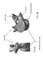
- Bonesconsist of cancellous bone covered by a thin layer of cortical bone as illustrated in FIG. 1 .
- Cancellous boneis a sponge-like bone structure which is less dense, softer, and weaker when compared to cortical bone.
- Bone screwsare utilized in surgery typically to stabilize and fix bone segments or to use as an anchor site within the bone. Most commonly, the screws are advanced through the outer cortical wall and anchored into the cancellous bone within.
- bi-cortical fixationcan be used to achieve greater purchase, as the screw is fixed within the stronger cortical bone at two separate points, the proximal and distal ends of the screw. Doing so increases the screw's pull out strength, which may be desirable at higher load levels, such as in the lower lumbar and sacrum of the spine.
- bi-cortical pedicle screw fixationIn the human vertebrae for example, the goal of bi-cortical pedicle screw fixation is to reach and thread the lead end of the screw into the anterior cortical wall. If the tip of the screw or associated instrumentation is advanced too far beyond the anterior cortical wall, the vital tissues that reside adjacent the anterior wall of the vertebrae, the great vessels for example, may be put at risk. Even with utilization of intraoperative fluoroscopy, safely gauging a screw's position can be difficult. As illustrated in FIG.
- the curvature of the anterior cortical wall of the vertebral bodymay cause difficulty correctly determining the position of a screw from a lateral view, such that in the lateral fluoroscope image the distal end of the screw may appear to be contained within the vertebra since the final depth of the distal end may be less than the vertebral depth at the anterior most portion ( FIG. 2A ).
- the actual screw position, FIG. 2Bis such that the distal end of the screw protrudes beyond the anterior cortical wall but at a position where the depth of the wall is less than the greatest depth near the center.
- the method of bi-cortical screw fixationutilizes a system of instruments with implants to achieve safe and repeatable bi-cortical fixation of screws.
- the methodmay be used for bi-cortical fixation in most bone segments and is well suited for use when securing pedicle screws in a vertebral body.
- a methodis described for use in the sacrum.
- the methodbegins by placement of a K-wire through the posterior cortical wall of a vertebral pedicle, via a Jamsheedi needle.
- One or more dilatorsare then inserted over the K-wire to dilate the tissues adjacent the K-wire.
- the dilatorsinclude a first, second, and third dilator of increasingly larger diameter. The dilators are advanced until their lead end contacts the bone surface of the pedicle.
- a contour probe with reference scalemay be advanced through the outer (e.g. third) dilator (after removal of the first and second dilators) to the pedicle.
- This instrumentwill assist the surgeon in measuring the magnitude of surface irregularity at the pedicle. The surgeon can then determine if there is a need for use of a bone reamer to create a flat pedicle surface and to gauge the depth of reaming desired. If needed, a cannulated bone reamer is guided down the K-wire and rotated sufficiently against the bone to the predetermined depth therein creating a uniform bone surface at the pedicle site.
- the resulting flat pedicle surface situated perpendicular to the guide wireserves as a level seat for the distal end of the second dilator, increasing the accuracy (if necessary) with which an exposed proximal end of the dilator can be used as reliable reference point to measure the depth of the vertebra later in the technique.
- bone shavingsmay be removed by suction or other instruments.
- the second dilatoris reinserted into the third dilator and advanced until seated against the bone or newly created uniform bone surface.
- a cannulated blunt-tip probeis advanced over the guide wire and down the second dilator into the cortical wall pilot hole created by the Jamsheedi needle.
- the probeincludes a blunted tip suitable to burrow through the cancellous bone within the vertebral body, extending the pilot hole and establishing a desired trajectory through the vertebra. While the blunt-tip probe effectively traverses through the softer cancellous bone, the probe is ineffective at puncturing the denser cortical bone. Thus, when the probe tip arrives at the anterior cortical wall, the probe experiences a hard stop and further advancement of the probe is inhibited.
- reference markers near the proximal end of the probeare consulted (relative to the end of the dilator) to determine the depth to the anterior cortical wall, which can be later used to determine the desired tap depth and screw length.
- the third dilatoris preferably fixed in position in alignment with the pilot hole trajectory. Fixing of the dilator may be achieved by attachment of a fixing arm to a fixator portion on the third dilator.
- the fixing armmay take several forms such as an A-arm attached to the operating table or other fixed device. Fixedly aligning the dilator with the pilot hole trajectory advantageously allows the K-wire to be removed during the subsequent tapping and screw insertion steps.
- a tapis advanced through the second dilator which ensures alignment with the previously prepared pilot hole (by virtue of being constrained within the third dilator, which has a fixed trajectory; the second dilator is also fixed).
- the desired tap depth to penetrate and tap the cortical wall without extending too far beyond the cortical wallcan be determined, allowing for controlled piercing of the cortical wall.
- An adjustable safety stop on the tapis used to control the depth to which the tap can be received through the second dilator and thus also, the depth the tap can advance through the vertebra.
- the desired size pedicle screwmay be chosen based on the determined depth of the vertebra.
- the pedicle screwis attached to the screw inserter then advanced down the third dilator (the second dilator having been removed) and under rotation advanced through the bone until reaching the desired bi-cortical position.
- the screw insertermay also include reference markings and/or adjustable depth stop as still an additional feature for controlling screw depth.
- Reference markings on the instrumentsmay be in a variety of forms, including numbers reflective of relative distances or depths, hash marks, grooves, ridges, color codes, or other visual or tactile indicator capable of providing measurement or sizing feedback to the user.
- the reference markingsmay represent a specified depth, or direct the user to a particular screw size or instrument choice.
- FIG. 1is a cross-sectional view along a median sagittal plane of a human vertebra.
- FIG. 2Ais a lateral view representative of a false negative indication of cortical wall breach that is possible on a lateral fluoroscopic image.
- FIG. 2Bis a perspective view of the vertebra and screw of FIG. 2A , illustrating the actual position of the pedicle screw extending beyond anterior cortical wall.
- FIG. 3is a front perspective view of an example embodiment of a first dilator with a K-wire.
- FIG. 4is a front perspective view of an example embodiment of a second dilator concentrically positioned over the first dilator and K-wire of FIG. 3 .
- FIG. 5is a front perspective view of the nose of the first dilator of FIG. 3 .
- FIG. 6is a top perspective view of an example embodiment of a third dilator.
- FIG. 7is a bottom perspective view of a the third dilator of FIG. 6 .
- FIG. 8is a front perspective close up view of an example embodiment of a fixator used in a third dilator.
- FIG. 9is a top perspective view of the third dilator of FIG. 6 .
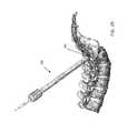
- FIG. 10is a front perspective view of an example embodiment of a blunt-tip probe.
- FIG. 11is a front perspective close up view of the blunt tip of the probe illustrated in FIG. 10 .
- FIG. 12is a front perspective view of an example embodiment of a bone tap with safety stop.
- FIG. 13is a close up view of a distal portion of the tap of FIG. 12 with the safety stop mechanism.
- FIG. 14is a front perspective close up view of the tap tip of FIG. 12 .
- FIG. 15is a front perspective view of an example embodiment of a tap's safety stop assembly.
- FIG. 16is a front perspective view of a release used within a safety stop.
- FIG. 17is a front perspective view of an example embodiment of a bone reamer.
- FIG. 18is a front perspective view of an example embodiment of a pedicle contour probe.
- FIG. 19is a front perspective close up view of the tip of the probe in FIG. 18 .
- FIG. 20is a front perspective view of a pedicle screw.
- FIG. 21is a front perspective view of a pedicle screw with associated insertion instruments used in minimally invasive procedures.
- FIG. 22is a cross-sectional sagittal plane view through the pedicles of the lumbar spine illustrating proper placement of a guidewire, according to one example method for achieving bi-cortical screw fixation using the instruments of FIGS. 3-21 .
- FIG. 23is a cross-sectional sagittal plane view through the pedicles of the lumbar spine illustrating placement of an first dilator, a second dilator, and a third dilator against the bone segment, according to the example method.
- FIG. 24is a cross-sectional sagittal plane view through the pedicles illustrating insertion of the reamer, according to the example method referenced in FIG. 23 .
- FIG. 25is a lateral view of a blunt tip probe creating a pilot hole in the vertebrae, according to the example method referenced in FIG. 23 .
- FIG. 26is a cross-sectional sagittal plane view through the pedicles of FIG. 25 illustrating the blunt tip probe creating a pilot hole in the vertebrae.
- FIG. 27is a lateral view of a tap creating thread in the pilot hole in the vertebrae, according to the example method referenced in FIG. 23 .
- FIG. 28is a cross-sectional sagittal plane view through the pedicles of FIG. 27 illustrating the tap creating thread in the pilot hole in the vertebrae.
- FIG. 29is a lateral view of the spine illustrating a pedicle screw with attached insertion instruments advanced into the pedicle, according to the example method referenced in FIG. 23 .
- FIGS. 3-21illustrate various example embodiments of instruments used during the later described method.
- FIG. 3illustrates a first dilator advanced to the target pedicle (e.g. the S1 pedicle) over a K-wire (the K-wire having been positioned in the pedicle using a jamsheedi needle, not shown).
- a plurality of dilatorsare used to dilate the tissues surrounding the K-wire to provide access to the pedicle.
- the K-wiredefines an elongated axis ‘A’ that serves as a surgical guide path through the body to the entry point on the pedicle.
- the dilator having the smallest outer diameteris the first dilator 101 comprising an elongated tube body 106 of sufficient length to extend from the surface of the bone to a distance above the skin.
- An outer surface 107 of dilator 101resides on the exterior of the dilator body 106 . This surface 107 , preferably smooth, slides along the soft tissues of the body while radially stretching them to provide passage of the first dilator 101 down to the bone segment.
- the nose 104 portionAt the distal or lead end 103 portion of the first dilator 101 is the nose 104 portion.
- the nose 104is preferred to be of a rounded cone or bullet shape. As the first dilator 101 is advanced, the surface of the leading smaller diameter portion of the nose 104 begins to gradually dilate the surrounding tissues to the full diameter of the nose 104 .
- an aperture 105Central to the nose is an aperture 105 that extends the length of the first dilator 101 and defines an inner elongated wall 110 of the dilator 101 as illustrated in FIG. 5 .
- the aperture 105is of a diameter slightly larger than the K-wire 100 such that the first dilator 101 can freely slide down the wire 100 without permitting ingress of tissue between the dilator and K-wire.
- the aperture 105 diametermay increase in diameter as it moves along the body 106 towards the proximal end 108 portion to prevent binding between the K-wire and the inner walls 110 of the aperture 105 .
- distal stop surface 111At the distal end of the nose 104 , is distal stop surface 111 that abuts against the bone when fully advanced down surgical path A.
- a grip portion 109may be included on or inscribed into surface 107 at the proximal end 108 of elongated body 106 .
- the grip portion 109may take a variety of forms to improve the surgeon's grasp on the dilator 101 as the dilator is directed toward the bone segment.
- the grip 109is in the form of a knurled surface but alternatively may be in the form of a polymer sleeve pulled over a recessed area of the elongated body 106 .
- proximal stop surface 112At the proximal end is proximal stop surface 112 .
- FIG. 4illustrates a second dilator 150 of the plurality of dilators, an intermediate dilator placed concentrically over the first dilator 101 and K-wire/guidewire 100 .
- the second dilator 150 in this preferred embodimentis a replica of the first dilator 101 but varies dimensionally in diameter and length.
- the inner elongated wall 110 of the second dilator 150is sized slightly larger in diameter than outer diameter of body 106 of the first dilator 101 wherein the second dilator 150 will glide over the first dilator 101 .
- the body 106 of second dilator 150comprises an outer diameter slightly smaller than the inner wall 110 of the third dilator 200 illustrated in FIGS.
- third dilator 200can freely glide over second dilator 150 .
- gaps between inner and outer dilator surfacesare sufficient to pass one dilator over the other, these gaps are minimized to prevent soft tissue from embedding within the gaps as increasingly larger dilators are advanced down the surgical axis.
- the length of second dilator 150is preferably sized wherein when stop surface 111 abuts against bone, grip portion 109 is fully exposed above the patient's skin as well as above the entire proximal end of third dilator 200 .
- the length of first dilator 101exceeds both the second dilator 150 and third dilator 200 wherein when first dilator 101 stop surface 111 abuts against bone, first dilator 101 grip portion 109 is fully exposed above proximal end 108 of second dilator 150 .
- FIGS. 6 , 7 , 8 & 9illustrate views of a preferred embodiment of the third dilator 200 (e.g. the final dilator according to the example embodiments described herein).
- the third dilator 200comprises an elongated body 106 with an inner elongated wall 110 defining a central aperture 220 .
- This central aperture 220is of sufficient diameter to slide over surface 107 of second dilator 150 as described previously and in addition is sufficient to provide passage for pedicle screw 151 and screw insertion instruments 153 such as those seen in FIGS. 20 & 21 .
- An outer surface 107resides on the elongated body 106 of the third dilator 200 .
- the body 106terminates at proximal screw face 224 on the proximal end 108 .
- the third dilator 200comprises one or more fixator portions 201 .
- the fixator 201is an extension of the proximal dilator body 106 in the form of a fixation boss 202 .
- the boss 202comprises a top surface 204 , a bottom surface 205 , and a side wall 208 .
- An inner wall 203defines an aperture 207 extending through the top 204 and bottom surfaces 205 .
- the aperture 207may comprise threads 206 and is configured to house a fixator lock 209 portion ( FIG. 8 ).
- the fixator lock 209comprises an elongate body 212 to be received in aperture 207 .
- the outer surface of elongate body 212has threads complementing those threads 206 in aperture 207 for a threaded engagement.
- fixator lock 209may utilize a press fit when non-threaded.
- An inner wall 213defines a central threaded aperture through body 212 .
- a fixator face 210is illustrated here in the form of radially spaced inclined teeth 211 .
- a stop 214in the form of a ridge abuts the fixator lock top surface 204 when fully seated into aperture 207 .
- a notch 215partially houses interference locking pin 216 along with bore 218 in top surface 204 by press fit. The pin 216 , when pressed into position prevents derotation and thus loosening of fixator lock 209 once seated in fixation boss 202 .
- the fixator lock 209is the site for attachment of a fixation apparatus such as an A-arm which on one end is clamped to the surgical table or other immovable apparatus.
- the free end of the A-armcomprises a locking fixator with locking features complementing the fixator lock 209 described herein.
- the free end of an A-armmay comprise a threaded fastener for advancing in the threaded inner wall 213 , along with a post for housing within stabilization bore 219 , and fixator face complementary to fixator face 210 . Tightening of said fastener draws the A-arm tight to the fixator lock therein securely fixing the fixator lock 209 to the A-arm.
- a plurality of fixators 201 with various size fixator locks 209are included.
- fixator lock 209is formed as a separate part of third dilator 200
- the body 106 of dilator 200may be manufactured from an anodized aluminum or a polymer like Radel, whereas the fixator lock 209 of FIG. 8 may be a stainless steel.
- the fixator portion 201 of third dilator 200may take many other forms suitable for fixing the dilator 200 in a predetermined position during surgery.
- fixator face 210may be machined into top surface 204 along with stabilization bore 219 and threaded inner wall 213 wherein the A-arm clamps directly to the fixator face 210 integral with fixation boss 202 .
- fixator 201As an alternate form of fixator 201 (not shown), one or more elongated channels integral to outer dilator surface 107 and parallel with axis E may be utilized to house fixation pins that thread or penetrate directly into the bone therein holding third dilator tight to the bone surface.
- the fixator 201may be in the form of a post extending outward radially about axis E from surface 107 at the proximal end 108 of third dilator 200 .
- the fixator 201may be in the form of dilator surface 107 at the proximal end 108 of third dilator 200 .
- the free-end of the A-armmay comprise a circumferential clamp configured to encircle the outer circumference of the tube.
- the third dilatormay be provided with a handle that me be used by the surgeon or assistant to hold the third dilator in the desired position.
- the third dilator 200has an outside taper 221 to improve movement through tissue that thins into scalloped teeth 222 at distal end 103 .
- the teeth 222may be sharpened 223 . These teeth 222 lodge into bone when third dilator 200 is fully advanced into the surgical site and serve as yet another means to fix the dilator 200 . It is not necessary that teeth 222 all reside in the same plane since the pedicle bone surface may not necessarily be flat. Therefore the teeth 222 may be profiled to best fit the contour of the pedicle bone surface.
- the example embodiment of the third dilatorincludes a flat (unsloped) distal tip with teeth serrations
- an alternative optionmay include sloped end (with or without teeth serrations) that would approximate the slope of the sacrum adjacent the S1 pedicle.
- the dilatorsmay be manufactured of materials such as polymers (e.g. Radel), carbon fiber, aluminum, titanium, or stainless steel alloys.
- the instruments used hereinare preferably manufactured from aluminum, titanium or stainless steel alloys. Other materials having suitable performance characteristics may also be used.
- FIGS. 10 and 11Illustrated in FIGS. 10 and 11 is a preferred embodiment of a blunt tip probe 300 configured to slide within inner cannula wall 110 of second dilator 150 .
- the probe 300comprises an elongated body 301 with central cannula 302 along axis B extending the entire length of body 301 .
- the cannula 302defines an inner wall 303 of said elongated body 301 .
- a blunt tip 304 illustrated in FIG. 11having a bulbous end 305 .
- Blunt tip 304may include one or more external serrations 306 to assist with pilot hole extension when the instrument is advanced through cancellous bone.
- distal surface 308utilized to push through cancellous bone during pilot hole extension.
- Probe 300is configured to slide within inner elongated walls 110 of second dilator 150 .
- the probe arm 309 portionis a distal end portion 103 of body 301 that narrows for a length of D which is sufficient to span from the outer surface of the pedicle to the anterior side of the anterior cortical wall for pilot hole extension through the cancellous bone.
- Proximal to the probe arm 309may be a diameter transition 310 wherein the diameter of outer surface 311 of body 301 increases to a diameter just less than inner cannula diameter of the inner elongated wall 110 of second dilator 150 .
- This diameter transition 310may be in different forms such as a fillet as illustrated in FIG. 10 , a chamfer, or a step.
- the combination of the narrow probe arm 309 with blunt tip 305 and the thicker body 301permits the probe to advance through cancellous bone to extend the pilot started by the Jamsheedi with enough rigidity to withstand bending (as opposed to typical ball tip probes), such that length measurements taken from the probe are not skewed, while lacking the ability under normal insertion forces to penetrate through cortical bone.
- probe reference 312On outer surface 311 is probe reference 312 , illustrated in FIG. 10 as a series of black circumferential etched lines but may take other forms.
- probe reference 312may be in the form of grooves, hash marks, or depressions, and may be color coded or marked with alpha-numeric characters.
- the reference marks 312are tied to the length of the second dilator and are indicative of the length to which the distal end of the probe advances beyond the distal end of the second dilator 150 .
- the distance the distal end of the probe 300 extends beyond the distal end of the second dilator 150corresponds to the depth of the vertebra from the outer wall of the pedicle to the inner surface of the anterior cortical wall.
- Probe 300may also comprise a neuromonitoring connection 313 configured for attachment of neuromonitoring accessory (e.g. stimulation clip, not shown) for monitoring pedicle integrity (e.g. detecting breaches of the pedicle wall) during advancement of the probe through the pedicle.
- neuromonitoring accessorye.g. stimulation clip, not shown
- pedicle integritye.g. detecting breaches of the pedicle wall
- connector 313is in the form of a conductive circumferential body 301 for attachment of a stimulation clip.
- Connector 313is typically located near proximal end 108 to avoid interfering with the surgical entry site.
- Body 301comprises one or more torque faces 315 for transmitting torque from the handle through body 301 , one or more lock faces 314 for temporary locking of the handle to body 301 , and an axial face 318 to transmit axial forces from the handle down body 301 .
- body 301may extend proximally and be formed into the shape of a handle or be configured to accept a handle thereon such as in the form of a rubber grip.
- Bone tap 400configured to slide within inner cannula wall 110 of second dilator 150 .
- Bone tap 400comprises an elongated body 401 with central cannula 402 along axis F extending the entire length of body 401 .
- the cannula 402defines an inner wall 403 of said elongated body 401 .
- tap shaft 404shown in FIG. 12 and that further comprises fluted 409 tap tip 439 with radial cutting teeth 407 formed by tap thread 408 and cutting face 405 that includes one or more forward cutting teeth 406 to assist with penetration of the anterior cortical wall.
- Bone tap 400is configured to slide within inner elongated walls 110 of second dilator 150 .
- the tap arm 410 portionis a distal end portion 103 of body 401 that narrows for a length D as introduced earlier. Length D is sufficient in length to span from the outer surface of the pedicle to the anterior side of the anterior cortical wall for taping threads along pilot hole.
- Proximal to the tap arm 410may be a diameter transition 419 wherein the diameter of outer surface 411 of body 401 increases to a diameter just less than inner cannula diameter created by the inner elongated wall 110 of second dilator 150 .
- this diameter transition 419may be in the form of a fillet as illustrated in FIG. 12 , a chamfer, or a step.
- tap reference 412illustrated in FIG. 13 as a series of hash lines but may take other forms.
- tap reference 412may be in the form of grooves, circumferential etched lines, or depressions, and may be color coded or marked with alpha-numeric characters suitable for determining the depth of the instrument with respect to anatomical structures of the patient or to other instruments.
- Tap 400also includes a safety stop 421 also illustrated in FIGS. 13 , 15 and 16 .
- Safety stop 421adjusts along depth ladder 422 corresponding to the tap reference 412 .
- depth ladder 422comprises a generally rectangular cross-section with a plurality of depth notches 423 on lateral sides of the rectangle configured to serve as incremental stop positions engaging safety stop 421 .
- safety stop 421comprises a housing 426 with radial surface 427 and a pair of opposing side surfaces 424 . Centered along axis K, ladder bore 425 with profile complementing depth ladder 422 extends through opposing side surfaces 424 .
- release bore 428extends through radial surface 427 to house release 429 .
- Release 429 in this embodimenthas a generally a square shaped ring body 430 with an exposed activation surface 431 , a pair of opposing legs 432 , and a bottom strut 433 .
- spring surface 434On the backside of bottom strut 433 is spring surface 434 .
- Within ring body 430resides ring bore 435 of a generally rectangular shape. Extending from inside the legs 432 and bottom strut 433 are cogs 436 .
- Each cog 436has opposing side surface 437 and top surface 438 .
- release 429is housed in release bore 428 .
- a biasing element(not shown), preferably in the form of a spring and situated within release bore 428 and behind spring surface 434 , biases release 429 outward causing cogs 436 to move towards central axis K for engagement of depth notches 423 therein causing safety stop 421 to lock in desired position along depth ladder 422 .
- Side surface 424serves as a stop against proximal stop surface 112 of second dilator 150 wherein tap is limited to a depth predetermined by the user. Accordingly, the depth stop can be set based on the measured depth of the vertebra such that the distal end may be advanced into but not through the anterior cortical wall.
- the safety stop 421may take on a variety of forms.
- itmay be in the form of a resilient ring that expands upon force of the user, adjusted to a new position, then contracts back around a complementary depth ladder recess.
- stop 421may be in the form of a threaded nut translating up and down a threaded depth ladder.
- the buttonis in the shape of a ball detent mechanism, in which this mechanism contains ball bearings that lock into mating grooves on the instrument shaft. Ball detent mechanisms are a popular choice in similar designs.
- Tap 400may also comprise a neuromonitoring connection 413 configured for attachment of a neuromonitoring accessory (e.g. stimulation clip, not shown) for monitoring pedicle integrity (e.g. detecting breaches of the pedicle wall) during advancement of the tap through the pedicle.
- a neuromonitoring accessorye.g. stimulation clip, not shown
- pedicle integritye.g. detecting breaches of the pedicle wall
- connector 413is in the form of a conductive circumferential body for attachment of a stimulation clip.
- Connector 413is typically located near proximal end 108 to avoid interfering with the surgical entry site.
- Body 401comprises one or more torque faces 415 for transmitting torque from the handle through body 401 , one or more lock faces 414 for temporary locking of the handle to body 401 , and at least one axial face 418 to transmit axial forces from the handle down body 401 .
- body 401may extend proximally and be formed into the shape of a handle or be configured to accept a handle thereon such as in the form of a rubber grip.
- Reamer 500comprises an elongate body 501 with outer surface 511 .
- a central cannula 502sufficient to house a guide wire, defines an inner wall of the cannula.
- reamer head 504configured at the preferred trajectory for removing uneven or angled bone at the surface of the pedicle when driven under rotation against a bone surface.
- Reamer head 504comprises a distal face 505 to abut against the bone surface, one or more axial reamer blades 506 for shaving the surface of the bone, a radial bone channel 507 to house bone chips as they are cut, and axial channel 508 as a path for bone chips to move into chip pocket 509 .
- the instrumentis a handle portion 510 configured for grasping by the user.
- the handlemay include a grip 512 here shown in the form of axial grooves or knurling in body 501 .
- FIGS. 18-19illustrate a preferred embodiment of a contour probe 600 .
- Contour probe 600may be utilized to map irregularities of the pedicle surface if desired. This information may be used to determine whether reaming is desirable, the depth of reaming required, and bone to yoke 152 spacing that may be necessary for proper polyaxial motion of the pedicle screw yoke.
- Contour probe 600comprises an elongate body 601 with an outer surface 602 of body 601 . Central to body 601 , an elongated cannula 605 , sufficient to receive a K-wire, defines an inner wall 606 of the cannula.
- a handle portion 607may include a grip 608 here shown in the form of radial grooves or knurling in body 601 to improve grip of the instrument.
- a grip 608here shown in the form of radial grooves or knurling in body 601 to improve grip of the instrument.
- the tip 609laterally offset from axis P.
- the tip 609comprises an elongated tip arm 610 and is preferably rounded at contact surface 611 .
- a medial surface 612resides on the inside of tip arm 610 .
- the elongate body 602is configured with a diameter to pass through the inner elongated walls 110 of second dilator 150 or may alternatively be configured with larger outer surface 602 diameter when used within third dilator 200 .
- contour reference 613illustrated in FIG.
- the height of the proximal end of the probe relative to the second dilatoradjusts as the tip 609 is rotated around the pedicle. If the height variation is substantial the surgeon may optionally choose to use reamer 500 prior to inserting the blunt probe 300 , or prior to assessing the depth of the vertebra from the blunt tip probe prior to tapping.
- the following exemplary steps of a procedure using the instruments described aboveprovides an example method for safely and reproducibly achieving bi-cortical screw fixation at the S1 vertebral body. While described with relation to the fixation at the S1 body, the same method may be used other vertebral levels as well.
- the methodis two-fold beginning with determining the distance from the top most surface of the pedicle to the inner surface of the anterior cortical wall and in using this information to safely pierce the anterior cortex (anterior cortical wall) without extending the tap or screw anteriorly beyond the cortex further than necessary.
- methodsare described for maintaining guide at a stable and consistent trajectory such that tapping and screw insertion may be performed without advancement over a K-wire (which can be inadvertently advanced through the anterior cortical during such steps).
- the methodbegins with placement of a guidewire (K-wire) in a predetermined location in the sacral (S1) pedicle 700 ( FIG. 22 ).
- the K-wire 100acts to guide instruments and establish the screw trajectory to this location.
- the skinmay be incised over the pedicle at the desired entry point (e.g. approximately 1 cm lateral to the pedicle).
- a Jamsheedi needle(not shown) is inserted into the vertebra at the predetermined location. The stylet of the Jamsheedi is removed followed by insertion of the K-wire 100 though the remaining Jamsheedi cannula.
- the K-wire 100is inserted a distance one half the depth of the vertebrae or a distance to assure it is firmly seated within the bone without the K-wire 100 tip piercing beyond the distal cortical bone wall.
- their positionmay be monitored by intra-operative fluoroscopy and neurophysiology monitoring equipment.
- At least one, and preferably a series of sequential dilatorsare used to dilate down to the pedicle over the K-wire 100 .
- the surgeongrasps the first dilator 101 and directs aperture 105 over the loose end of K-wire 100 .
- the surgeonadvances the first dilator 101 down the surgical path stretching through the soft tissues surrounding the K-wire 100 until first dilator stop surface 111 abuts the bone.
- Inner elongated wall 110 of second dilator 150is then directed over outer surface 107 of first dilator 101 , again stretching through the surrounding soft tissue until stop surface 111 of second dilator 150 abuts the targeted S1 pedicle.
- the central aperture 220 of third dilator 200is then advanced down over second dilator surface 107 therein fully stretching surrounding soft tissue out of its path until teeth 222 contact the S1 pedicle bone surface.
- contour probe 600may be utilized to map the pedicle surface for irregularities. This is performed by removing the second dilator 150 and first dilator 101 away from the surgical site. Elongated cannula 605 of contour probe 600 is then advanced over K-wire 100 until contact surface 611 abuts the bone. At the anticipated screw trajectory, the user then monitors depth changes in reference 613 compared to proximal screw face 224 of third dilator 200 as contour probe 600 is rotated over the surface of the pedicle. Small to no reference change indicates little surface height variation whereas large reference changes indicate large changes in surface height.
- the surgeonmay choose to level the pedicle surface using a bone reamer 500 to create a flat bone surface before reinsertion of second dilator 150 in later steps ( FIG. 24 ).
- Utilizing the bone reamercreates a flat bone surface against which the second dilator sits to facilitate depth measurement with the blunt tip probe 300 .
- the useradvances central cannula 502 of bone reamer 500 over K-wire 100 until distal face 505 abuts the bone surface and places rotational and axial force through handle 510 toward the vertebrae causing reamer blades 506 to cut the bone and resulting in a level surface.
- the bone reamer 500is then removed. Bone chips may be removed from the site by hand instruments or suction.
- Second dilator 150is then reinserted down central aperture 220 of third dilator 200 until contacting pedicle bone surface.
- the pilot hole initially created by the Jamsheedi needle through the posterior cortical wall of the pedicleis extended through the cancellous bone to the inner surface of the anterior cortical wall ( FIG. 25 ).
- neuromonitoringmay be performed to ensure the pilot hole extends distally through the pedicle and does not breach the pedicle wall.
- Central cannula 302 of blunt-tip probe 300is advanced over K-wire 100 into the pilot hole created by the jamsheedi.
- the surgeonusing grip portion 317 , continues with controlled advancement of probe 300 through the softer cancellous bone until a harder stop is felt through the instrument indicating abutment of distal surface 308 with the inner surface of the anterior cortical wall.
- a depth readingis noted from probe reference 312 in view of proximal stop surface 112 of second dilator 150 .
- the references on the probeare calibrated wherein the user can directly read a depth ‘Y’ from the reference where the reference aligns with the proximal stop surface 112 indicating the depth of the distal surface 308 of probe 300 beyond the distal stop surface 111 of the second dilator 150 , which corresponds to the depth of the vertebra from posterior pedicle wall to inner surface of the anterior cortical wall.
- third dilator 200is concentrically aligned to this path, by virtue of the second dilator 150 being aligned with the probe, and fixed in place by attachment of fixator lock 209 of third dilator 200 to an articulating arm (A-arm) or compatible handle.
- the articulating arm(not shown) locks against fixator face 210 with screw fixation through stabilization bore 219 and threading into inner wall 213 ( FIGS. 6-9 ).
- the surgeonmay choose to drive or tap proximal screw face 224 of third dilator 200 to seat teeth 222 in pedicle bone as illustrated in FIG. 23 .
- the hole trajectoryis defined therein providing for concentric alignment of the pilot hole, tap, and screw placement. K-wire 100 and blunt tip probe 300 are no longer necessary and are removed.
- Bone tap 400is utilized to tap the pilot hole in the bone in preparation of screw 151 insertion. Tap 400 is also used to provide a controlled method of piercing the anterior cortical wall. As discussed earlier, tap reference 412 and probe reference 312 may be calibrated to provide the same depth reading on each instrument when at identical bone depths while also indicating the depth of penetration into the bone. Bone tap 400 features optional safety stop 421 . In this embodiment, the safety stop is adjustable in 2.5 mm increments.
- depth ‘Y’is recalled. Assuming for example, the anterior cortical wall to be 2.5 mm thick, 2.5 mm is added to depth reading ‘Y’ for sum ‘Q’. Sum Q represents the tap depth required to pierce the anterior cortical wall. Distal facing side surface 424 of safety stop 421 is aligned with the tap reference 412 value equal to sum Q by depressing activation surface 431 and sliding safety stop 421 along depth ladder 422 . For example: If the second blunt-tip probe reference 312 reading is 45 mm, then distal facing side surface 424 is aligned with reading 47.5 mm. This step provides controlled piercing of the anterior cortical wall without the tap over extending anteriorly.
- Neuromonitoringmay again be performed during tapping to ensure the tap does not breach the pedicle wall.
- Tap shaft 404 of bone tap 400is led to pilot hole through the second dilator, along the trajectory fixed via the third dilator, and advanced with rotation causing tap thread 408 to tap pilot hole.
- distal facing side surface 424abuts proximal stop surface 112 of second dilator 150 , the pilot hole is threaded to the desired depth. Rotation of tap can now be reversed and tap 400 removed from surgical path, followed by the second dilator.
- the surgeonwill then choose an appropriate screw length for bi-cortical purchase.
- the surgeonmay choose a screw 151 length to compensate for any amount of spacing she may desire between yoke 152 and the pedicle bone surface for full poly-axial motion of the yoke 152 .
- the surgeonmay also choose a slightly longer screw to assure threads have full purchase in the anterior cortical wall yet have minimal protrusion.
- Pedicle screw 151 with attached insertion instruments 153is now centered then advanced down screw path trajectory defined by central aperture 220 of fixed third dilator 200 and pre-threaded pilot hole. Because the screw length is selected based on the predetermined vertebra depth, monitoring insertion depth of the inserter is not necessary. However, the screw insertion instruments may also have an inserter reference 154 similar to that seen on other instruments. Because the second dilator 150 is removed and cannot be utilized as a depth reference, however, the reference on the screw inserter may be made to account for the difference in length between the second dilator and the third dilator. The above described steps may be completed for positioning of each pedicle screw to be implanted and the fixation construct may be completed with rod placement and construct locking.
Landscapes
- Health & Medical Sciences (AREA)
- Surgery (AREA)
- Orthopedic Medicine & Surgery (AREA)
- Life Sciences & Earth Sciences (AREA)
- Heart & Thoracic Surgery (AREA)
- Veterinary Medicine (AREA)
- Engineering & Computer Science (AREA)
- Biomedical Technology (AREA)
- Nuclear Medicine, Radiotherapy & Molecular Imaging (AREA)
- Medical Informatics (AREA)
- Molecular Biology (AREA)
- Animal Behavior & Ethology (AREA)
- General Health & Medical Sciences (AREA)
- Public Health (AREA)
- Neurology (AREA)
- Dentistry (AREA)
- Oral & Maxillofacial Surgery (AREA)
- Surgical Instruments (AREA)
Abstract
Description
Claims (10)
Priority Applications (1)
| Application Number | Priority Date | Filing Date | Title |
|---|---|---|---|
| US13/771,076US8936626B1 (en) | 2012-02-17 | 2013-02-19 | Bi-cortical screw fixation |
Applications Claiming Priority (2)
| Application Number | Priority Date | Filing Date | Title |
|---|---|---|---|
| US201261600576P | 2012-02-17 | 2012-02-17 | |
| US13/771,076US8936626B1 (en) | 2012-02-17 | 2013-02-19 | Bi-cortical screw fixation |
Publications (1)
| Publication Number | Publication Date |
|---|---|
| US8936626B1true US8936626B1 (en) | 2015-01-20 |
Family
ID=52301648
Family Applications (1)
| Application Number | Title | Priority Date | Filing Date |
|---|---|---|---|
| US13/771,076ActiveUS8936626B1 (en) | 2012-02-17 | 2013-02-19 | Bi-cortical screw fixation |
Country Status (1)
| Country | Link |
|---|---|
| US (1) | US8936626B1 (en) |
Cited By (22)
| Publication number | Priority date | Publication date | Assignee | Title |
|---|---|---|---|---|
| US20140046445A1 (en)* | 2012-08-10 | 2014-02-13 | William A. Brennan | Spinal stabilization system and method |
| US20150282855A1 (en)* | 2014-04-04 | 2015-10-08 | K2M, Inc. | Screw insertion instrument |
| US9277928B2 (en) | 2013-03-11 | 2016-03-08 | Interventional Spine, Inc. | Method and apparatus for minimally invasive insertion of intervertebral implants |
| US9486149B2 (en) | 2011-03-10 | 2016-11-08 | Interventional Spine, Inc. | Method and apparatus for minimally invasive insertion of intervertebral implants |
| US9492194B2 (en) | 2011-03-10 | 2016-11-15 | Interventional Spine, Inc. | Method and apparatus for minimally invasive insertion of intervertebral implants |
| WO2017127502A1 (en)* | 2016-01-19 | 2017-07-27 | K2M, Inc. | Tissue dilation system and methods of use |
| US20170311932A1 (en)* | 2016-04-29 | 2017-11-02 | Devicor Medical Products, Inc. | Depth stop device for use with biopsy targeting assembly |
| US9993353B2 (en) | 2013-03-14 | 2018-06-12 | DePuy Synthes Products, Inc. | Method and apparatus for minimally invasive insertion of intervertebral implants |
| US10321833B2 (en) | 2016-10-05 | 2019-06-18 | Innovative Surgical Solutions. | Neural locating method |
| EP3517058A1 (en)* | 2018-01-30 | 2019-07-31 | Tornier | Surgical bone preparation instrument and assembly comprising such an instrument |
| US10376208B2 (en) | 2013-09-20 | 2019-08-13 | Innovative Surgical Solutions, Llc | Nerve mapping system |
| US10376209B2 (en) | 2013-09-20 | 2019-08-13 | Innovative Surgical Solutions, Llc | Neural locating method |
| US10449002B2 (en) | 2013-09-20 | 2019-10-22 | Innovative Surgical Solutions, Llc | Method of mapping a nerve |
| US10478097B2 (en) | 2013-08-13 | 2019-11-19 | Innovative Surgical Solutions | Neural event detection |
| US10478096B2 (en) | 2013-08-13 | 2019-11-19 | Innovative Surgical Solutions. | Neural event detection |
| US10792053B2 (en)* | 2017-10-31 | 2020-10-06 | Sicage Llc | Press system for setting a surgical device |
| US10870002B2 (en) | 2018-10-12 | 2020-12-22 | DePuy Synthes Products, Inc. | Neuromuscular sensing device with multi-sensor array |
| US10869616B2 (en) | 2018-06-01 | 2020-12-22 | DePuy Synthes Products, Inc. | Neural event detection |
| CN112656456A (en)* | 2021-01-04 | 2021-04-16 | 苏州市立普医疗科技有限公司 | Buoy for puncture needle |
| US11399777B2 (en) | 2019-09-27 | 2022-08-02 | DePuy Synthes Products, Inc. | Intraoperative neural monitoring system and method |
| US20230112058A1 (en)* | 2021-10-08 | 2023-04-13 | Nuvasive, Inc. | Assemblies, systems, and methods for a neuromonitoring drill bit |
| US20240261009A1 (en)* | 2021-06-22 | 2024-08-08 | Smith & Nephew, Inc. | Self-countersinking bone fastener and method for countersinking a bone fastener used in connection with an orthopedic implant |
Citations (87)
| Publication number | Priority date | Publication date | Assignee | Title |
|---|---|---|---|---|
| US4655216A (en) | 1985-07-23 | 1987-04-07 | Alfred Tischer | Combination instrument for laparoscopical tube sterilization |
| US5720751A (en) | 1996-11-27 | 1998-02-24 | Jackson; Roger P. | Tools for use in seating spinal rods in open ended implants |
| US6139549A (en) | 1996-04-09 | 2000-10-31 | Waldemar Link (Gmbh & Co.) | Spinal fixing device |
| US6183472B1 (en) | 1998-04-09 | 2001-02-06 | Howmedica Gmbh | Pedicle screw and an assembly aid therefor |
| US6235028B1 (en) | 2000-02-14 | 2001-05-22 | Sdgi Holdings, Inc. | Surgical guide rod |
| US20010021853A1 (en) | 2000-03-10 | 2001-09-13 | Richard Wolf Gmbh | Surgical instrument for applying implants |
| US6299616B1 (en) | 1998-11-07 | 2001-10-09 | Aesculap Ag & Co. Kg | Endoscopic insertion apparatus |
| US20020026195A1 (en) | 2000-04-07 | 2002-02-28 | Kyphon Inc. | Insertion devices and method of use |
| US6379364B1 (en) | 2000-04-28 | 2002-04-30 | Synthes (Usa) | Dual drill guide for a locking bone plate |
| US6440133B1 (en) | 2001-07-03 | 2002-08-27 | Sdgi Holdings, Inc. | Rod reducer instruments and methods |
| US6511484B2 (en) | 2001-06-29 | 2003-01-28 | Depuy Acromed, Inc. | Tool and system for aligning and applying fastener to implanted anchor |
| US6530929B1 (en) | 1999-10-20 | 2003-03-11 | Sdgi Holdings, Inc. | Instruments for stabilization of bony structures |
| US6547795B2 (en) | 2001-08-13 | 2003-04-15 | Depuy Acromed, Inc. | Surgical guide system for stabilization of the spine |
| US20030199872A1 (en) | 2002-04-17 | 2003-10-23 | Stryker Spine | Rod persuader |
| US20030208203A1 (en) | 2002-05-06 | 2003-11-06 | Roy Lim | Minimally invasive instruments and methods for inserting implants |
| US6648888B1 (en) | 2002-09-06 | 2003-11-18 | Endius Incorporated | Surgical instrument for moving a vertebra |
| US20030229354A1 (en) | 2002-06-07 | 2003-12-11 | Reinhold Schmieding | Method and system for intraoperatively revising the length of fracture fixation screws |
| US20040138662A1 (en) | 2002-10-30 | 2004-07-15 | Landry Michael E. | Spinal stabilization systems and methods |
| US20040147937A1 (en) | 2003-01-24 | 2004-07-29 | Depuy Spine, Inc. | Spinal rod approximators |
| US20050065517A1 (en) | 2003-09-24 | 2005-03-24 | Chin Kingsley Richard | Methods and devices for improving percutaneous access in minimally invasive surgeries |
| US20050085813A1 (en) | 2003-10-21 | 2005-04-21 | Innovative Spinal Technologies | System and method for stabilizing of internal structures |
| US20050131421A1 (en) | 2003-12-16 | 2005-06-16 | Anderson David G. | Methods and devices for minimally invasive spinal fixation element placement |
| US20050131422A1 (en) | 2003-12-16 | 2005-06-16 | Anderson David G. | Methods and devices for spinal fixation element placement |
| US20050131419A1 (en) | 2003-12-16 | 2005-06-16 | Mccord David | Pivoting implant holder |
| US20050131420A1 (en) | 2003-12-16 | 2005-06-16 | Techiera Richard C. | Pivoting implant holder |
| US20050131408A1 (en) | 2003-12-16 | 2005-06-16 | Sicvol Christopher W. | Percutaneous access devices and bone anchor assemblies |
| US6929606B2 (en) | 2001-01-29 | 2005-08-16 | Depuy Spine, Inc. | Retractor and method for spinal pedicle screw placement |
| US20050192589A1 (en) | 2004-02-06 | 2005-09-01 | Douglas Raymond | Devices and methods for inserting a spinal fixation element |
| US20050192570A1 (en) | 2004-02-27 | 2005-09-01 | Jackson Roger P. | Orthopedic implant rod reduction tool set and method |
| US20050192579A1 (en) | 2004-02-27 | 2005-09-01 | Jackson Roger P. | Orthopedic implant rod reduction tool set and method |
| US20050215999A1 (en) | 2004-03-19 | 2005-09-29 | Depuy Spine, Inc. | Spinal fixation element and methods |
| US6951538B2 (en) | 2001-01-29 | 2005-10-04 | Depuy Spine, Inc. | Retractor and method for spinal pedicle screw placement |
| US20050228380A1 (en) | 2004-04-09 | 2005-10-13 | Depuy Spine Inc. | Instruments and methods for minimally invasive spine surgery |
| US20050228400A1 (en) | 2004-03-31 | 2005-10-13 | Chao Nam T | Instrument for inserting, adjusting and removing pedicle screws and other orthopedic implants |
| US20050245928A1 (en) | 2004-05-03 | 2005-11-03 | Innovative Spinal Technologies | System and method for displacement of bony structures |
| US20050251139A1 (en) | 2004-05-07 | 2005-11-10 | Roh Jeffrey S | Systems and methods that facilitate minimally invasive spine surgery |
| US20060003624A1 (en) | 2004-06-14 | 2006-01-05 | Dow Richard M | Interposer structure and method |
| US20060036255A1 (en) | 2004-08-13 | 2006-02-16 | Pond John D Jr | System and method for positioning a connecting member adjacent the spinal column in minimally invasive procedures |
| US20060036244A1 (en) | 2003-10-21 | 2006-02-16 | Innovative Spinal Technologies | Implant assembly and method for use in an internal structure stabilization system |
| US20060069391A1 (en) | 2004-02-27 | 2006-03-30 | Jackson Roger P | Spinal fixation tool attachment structure |
| US20060074418A1 (en) | 2004-09-24 | 2006-04-06 | Jackson Roger P | Spinal fixation tool set and method for rod reduction and fastener insertion |
| US20060079909A1 (en) | 2003-12-17 | 2006-04-13 | Runco Thomas J | Instruments and methods for bone anchor engagement and spinal rod reduction |
| US20060079894A1 (en) | 2003-10-21 | 2006-04-13 | Innovative Spinal Technologies | Connector transfer tool for internal structure stabilization systems |
| US20060089651A1 (en) | 2004-10-26 | 2006-04-27 | Trudeau Jeffrey L | Apparatus and method for anchoring a surgical rod |
| US20060095035A1 (en) | 2004-11-03 | 2006-05-04 | Jones Robert J | Instruments and methods for reduction of vertebral bodies |
| US20060106394A1 (en) | 2004-11-16 | 2006-05-18 | Innovative Spinal Technologies, Inc. | Off-axis anchor guidance system |
| US20060111712A1 (en) | 2004-11-23 | 2006-05-25 | Jackson Roger P | Spinal fixation tool set and method |
| US20060111715A1 (en) | 2004-02-27 | 2006-05-25 | Jackson Roger P | Dynamic stabilization assemblies, tool set and method |
| US20060122597A1 (en) | 2004-12-02 | 2006-06-08 | Jones Robert J | Instruments and methods for adjusting separation distance of vertebral bodies with a minimally invasive spinal stabilization procedure |
| US20060200132A1 (en) | 2005-03-04 | 2006-09-07 | Chao Nam T | Instruments and methods for manipulating a vertebra |
| US20060247658A1 (en) | 2005-04-28 | 2006-11-02 | Pond John D Jr | Instrument and method for guiding surgical implants and instruments during surgery |
| US20060264934A1 (en) | 2005-05-18 | 2006-11-23 | Medicinelodge, Inc. | System and method for orthopedic implant configuration |
| US20060281838A1 (en) | 2005-06-08 | 2006-12-14 | Thomas Steinhausler | Non-provisional patent application |
| US20060293693A1 (en) | 2005-06-08 | 2006-12-28 | Innovative Spine, Llc | Sleeve assembly for spinal stabilization system and methods of use |
| US20070049931A1 (en) | 2005-08-26 | 2007-03-01 | Sdgi Holdings, Inc. | Instruments for minimally invasive stabilization of bony structures |
| US20070167949A1 (en) | 2004-10-20 | 2007-07-19 | Moti Altarac | Screw systems and methods for use in stabilization of bone structures |
| US20070233155A1 (en) | 2005-12-07 | 2007-10-04 | Lovell John R | Device and method for holding and inserting one or more components of a pedicle screw assembly |
| US20080005787A1 (en) | 2006-06-28 | 2008-01-03 | Siemens Medical Solutions Usa, Inc. | Software Distribution and License Management System |
| US20080024937A1 (en) | 2006-07-31 | 2008-01-31 | Hitachi Global Storage Technologies | CPP read sensor having constrained current paths made of lithographically-defined conductive vias with surrounding oxidized metal sublayers |
| US20080051787A1 (en) | 2006-08-22 | 2008-02-28 | Neuropro Technologies, Inc. | Percutaneous system for dynamic spinal stabilization |
| US20080077138A1 (en) | 2006-09-26 | 2008-03-27 | Cohen Dan S | Percutaneous instrument assembly |
| US20080073323A1 (en) | 1999-12-20 | 2008-03-27 | Full Robert J | Adhesive microstructure and method of forming same |
| US20080077135A1 (en) | 2006-09-26 | 2008-03-27 | Depuy Spine, Inc. | Minimally invasive bone anchor extensions |
| US20080091213A1 (en) | 2004-02-27 | 2008-04-17 | Jackson Roger P | Tool system for dynamic spinal implants |
| US20080132904A1 (en) | 2006-12-05 | 2008-06-05 | Usher John A | Screw insertion guide tube with window |
| US20080140132A1 (en) | 2006-12-07 | 2008-06-12 | Mi4Spine, Llc | Pedicle screw and rod system for minimally invasive spinal fusion surgery |
| US20080172062A1 (en) | 2007-01-12 | 2008-07-17 | Depuy Spine, Inc. | Bone anchor manipulation device |
| US20080275456A1 (en) | 2007-05-02 | 2008-11-06 | Zimmer Spine, Inc. | Installation systems for spinal stabilization system and related methods |
| US20080288005A1 (en) | 2004-02-27 | 2008-11-20 | Jackson Roger P | Orthopedic implant rod reduction tool set and method |
| US20080312703A1 (en) | 2007-06-12 | 2008-12-18 | Zimmer Spine, Inc. | Instrumentation and associated techniques for minimally invasive vertebral rod installation |
| US20080319477A1 (en) | 2007-06-21 | 2008-12-25 | Justis Jeff R | Anchor extenders for minimally invasive surgical procedures |
| US7481813B1 (en) | 2004-11-19 | 2009-01-27 | Alphatec Spine, Inc. | Securing device and corresponding methods thereof for bone fixation systems |
| US20090048601A1 (en) | 2007-08-15 | 2009-02-19 | Forton Charles R | Mis crosslink apparatus and methods for spinal implant |
| US20090082666A1 (en) | 2006-08-04 | 2009-03-26 | Wyatt Drake Geist | Magnetic targeting system for facilitating navigation |
| US20090131755A1 (en) | 2007-10-08 | 2009-05-21 | Patrick Michel White | Retractor for minimally invasive surgery |
| US20090143828A1 (en) | 2007-10-04 | 2009-06-04 | Shawn Stad | Methods and Devices For Minimally Invasive Spinal Connection Element Delivery |
| US20090171391A1 (en) | 2007-10-23 | 2009-07-02 | Alphatec Spine, Inc. | Systems and methods for spinal fixation |
| US20090216234A1 (en) | 2006-11-03 | 2009-08-27 | Innovative Spine | Spinal Access Systems and Methods |
| US7657308B2 (en) | 2003-08-05 | 2010-02-02 | Nuvasive, Inc. | System and methods for performing dynamic pedicle integrity assessments |
| US20100036495A1 (en) | 2008-08-07 | 2010-02-11 | PX Spine Corporation | Device and method for treating spine |
| US7664544B2 (en) | 2002-10-30 | 2010-02-16 | Nuvasive, Inc. | System and methods for performing percutaneous pedicle integrity assessments |
| US20100331883A1 (en) | 2004-10-15 | 2010-12-30 | Schmitz Gregory P | Access and tissue modification systems and methods |
| US7942826B1 (en) | 2005-06-06 | 2011-05-17 | Nuvasive, Inc. | Insulated pedicle access system and related methods |
| US20110230965A1 (en) | 2010-03-22 | 2011-09-22 | Gerald Schell | Percutaneous arthrodesis method and system |
| US20120022597A1 (en)* | 2005-02-23 | 2012-01-26 | Gephart Matthew P | Minimally Invasive Surgical System |
| US20120265250A1 (en) | 2011-03-18 | 2012-10-18 | Raed M. Ali, M.D., Inc. | Transpedicular access to intervertebral spaces and related spinal fusion systems and methods |
| US20130072986A1 (en)* | 2011-09-21 | 2013-03-21 | James C. Robinson | Fenestrated bone screws and methods of bone fastening and stabilization |
- 2013
- 2013-02-19USUS13/771,076patent/US8936626B1/enactiveActive
Patent Citations (102)
| Publication number | Priority date | Publication date | Assignee | Title |
|---|---|---|---|---|
| US4655216A (en) | 1985-07-23 | 1987-04-07 | Alfred Tischer | Combination instrument for laparoscopical tube sterilization |
| US6139549A (en) | 1996-04-09 | 2000-10-31 | Waldemar Link (Gmbh & Co.) | Spinal fixing device |
| US5720751A (en) | 1996-11-27 | 1998-02-24 | Jackson; Roger P. | Tools for use in seating spinal rods in open ended implants |
| US6183472B1 (en) | 1998-04-09 | 2001-02-06 | Howmedica Gmbh | Pedicle screw and an assembly aid therefor |
| US6299616B1 (en) | 1998-11-07 | 2001-10-09 | Aesculap Ag & Co. Kg | Endoscopic insertion apparatus |
| US7008422B2 (en) | 1999-10-20 | 2006-03-07 | Sdgi Holdings, Inc. | Instruments and methods for stabilization of bony structures |
| US20050021031A1 (en) | 1999-10-20 | 2005-01-27 | Foley Kevin T. | Instruments and methods for stabilization of bony structures |
| US7188626B2 (en) | 1999-10-20 | 2007-03-13 | Warsaw Orthopedic, Inc. | Instruments and methods for stabilization of bony structures |
| US7011660B2 (en) | 1999-10-20 | 2006-03-14 | Sdgi Holdings, Inc. | Instruments and methods for stabilization of bony structures |
| US6530929B1 (en) | 1999-10-20 | 2003-03-11 | Sdgi Holdings, Inc. | Instruments for stabilization of bony structures |
| US20080073323A1 (en) | 1999-12-20 | 2008-03-27 | Full Robert J | Adhesive microstructure and method of forming same |
| US6235028B1 (en) | 2000-02-14 | 2001-05-22 | Sdgi Holdings, Inc. | Surgical guide rod |
| US20010021853A1 (en) | 2000-03-10 | 2001-09-13 | Richard Wolf Gmbh | Surgical instrument for applying implants |
| US20020026195A1 (en) | 2000-04-07 | 2002-02-28 | Kyphon Inc. | Insertion devices and method of use |
| US6379364B1 (en) | 2000-04-28 | 2002-04-30 | Synthes (Usa) | Dual drill guide for a locking bone plate |
| US6951538B2 (en) | 2001-01-29 | 2005-10-04 | Depuy Spine, Inc. | Retractor and method for spinal pedicle screw placement |
| US6929606B2 (en) | 2001-01-29 | 2005-08-16 | Depuy Spine, Inc. | Retractor and method for spinal pedicle screw placement |
| US6511484B2 (en) | 2001-06-29 | 2003-01-28 | Depuy Acromed, Inc. | Tool and system for aligning and applying fastener to implanted anchor |
| US6440133B1 (en) | 2001-07-03 | 2002-08-27 | Sdgi Holdings, Inc. | Rod reducer instruments and methods |
| US6547795B2 (en) | 2001-08-13 | 2003-04-15 | Depuy Acromed, Inc. | Surgical guide system for stabilization of the spine |
| US20030199872A1 (en) | 2002-04-17 | 2003-10-23 | Stryker Spine | Rod persuader |
| US20030208203A1 (en) | 2002-05-06 | 2003-11-06 | Roy Lim | Minimally invasive instruments and methods for inserting implants |
| US20030229354A1 (en) | 2002-06-07 | 2003-12-11 | Reinhold Schmieding | Method and system for intraoperatively revising the length of fracture fixation screws |
| US6648888B1 (en) | 2002-09-06 | 2003-11-18 | Endius Incorporated | Surgical instrument for moving a vertebra |
| US20060142761A1 (en) | 2002-10-30 | 2006-06-29 | Landry Michael E | Spinal stabilization systems and methods |
| US7664544B2 (en) | 2002-10-30 | 2010-02-16 | Nuvasive, Inc. | System and methods for performing percutaneous pedicle integrity assessments |
| US20040172022A1 (en) | 2002-10-30 | 2004-09-02 | Landry Michael E. | Bone fastener assembly for a spinal stabilization system |
| US20060084993A1 (en) | 2002-10-30 | 2006-04-20 | Landry Michael E | Spinal stabilization systems and methods |
| US20040143265A1 (en) | 2002-10-30 | 2004-07-22 | Landry Michael E. | Spinal stabilization systems and methods using minimally invasive surgical procedures |
| US20040138662A1 (en) | 2002-10-30 | 2004-07-15 | Landry Michael E. | Spinal stabilization systems and methods |
| US20040147937A1 (en) | 2003-01-24 | 2004-07-29 | Depuy Spine, Inc. | Spinal rod approximators |
| US7657308B2 (en) | 2003-08-05 | 2010-02-02 | Nuvasive, Inc. | System and methods for performing dynamic pedicle integrity assessments |
| US20050065517A1 (en) | 2003-09-24 | 2005-03-24 | Chin Kingsley Richard | Methods and devices for improving percutaneous access in minimally invasive surgeries |
| US20060079894A1 (en) | 2003-10-21 | 2006-04-13 | Innovative Spinal Technologies | Connector transfer tool for internal structure stabilization systems |
| US20060106380A1 (en) | 2003-10-21 | 2006-05-18 | Innovative Spinal Technologies | Extension for use with stabilization systems for internal structures |
| US20060036244A1 (en) | 2003-10-21 | 2006-02-16 | Innovative Spinal Technologies | Implant assembly and method for use in an internal structure stabilization system |
| US20050085813A1 (en) | 2003-10-21 | 2005-04-21 | Innovative Spinal Technologies | System and method for stabilizing of internal structures |
| US7179261B2 (en) | 2003-12-16 | 2007-02-20 | Depuy Spine, Inc. | Percutaneous access devices and bone anchor assemblies |
| US20050131421A1 (en) | 2003-12-16 | 2005-06-16 | Anderson David G. | Methods and devices for minimally invasive spinal fixation element placement |
| US20050131422A1 (en) | 2003-12-16 | 2005-06-16 | Anderson David G. | Methods and devices for spinal fixation element placement |
| US20050131419A1 (en) | 2003-12-16 | 2005-06-16 | Mccord David | Pivoting implant holder |
| US20070167954A1 (en) | 2003-12-16 | 2007-07-19 | Christopher Sicvol | Percutaneous Access Devices And Bone Anchor Assemblies |
| US20050131420A1 (en) | 2003-12-16 | 2005-06-16 | Techiera Richard C. | Pivoting implant holder |
| US20050131408A1 (en) | 2003-12-16 | 2005-06-16 | Sicvol Christopher W. | Percutaneous access devices and bone anchor assemblies |
| US20050154389A1 (en) | 2003-12-16 | 2005-07-14 | Depuy Spine, Inc. | Methods and devices for minimally invasive spinal fixation element placement |
| US20060079909A1 (en) | 2003-12-17 | 2006-04-13 | Runco Thomas J | Instruments and methods for bone anchor engagement and spinal rod reduction |
| US20050192589A1 (en) | 2004-02-06 | 2005-09-01 | Douglas Raymond | Devices and methods for inserting a spinal fixation element |
| US20060111715A1 (en) | 2004-02-27 | 2006-05-25 | Jackson Roger P | Dynamic stabilization assemblies, tool set and method |
| US20080091213A1 (en) | 2004-02-27 | 2008-04-17 | Jackson Roger P | Tool system for dynamic spinal implants |
| US20060069391A1 (en) | 2004-02-27 | 2006-03-30 | Jackson Roger P | Spinal fixation tool attachment structure |
| US20050192570A1 (en) | 2004-02-27 | 2005-09-01 | Jackson Roger P. | Orthopedic implant rod reduction tool set and method |
| US20050192579A1 (en) | 2004-02-27 | 2005-09-01 | Jackson Roger P. | Orthopedic implant rod reduction tool set and method |
| US20080288005A1 (en) | 2004-02-27 | 2008-11-20 | Jackson Roger P | Orthopedic implant rod reduction tool set and method |
| US20100004696A1 (en) | 2004-02-27 | 2010-01-07 | Jackson Roger P | Orthopedic implant rod reduction tool set and method |
| US20050215999A1 (en) | 2004-03-19 | 2005-09-29 | Depuy Spine, Inc. | Spinal fixation element and methods |
| US20050228400A1 (en) | 2004-03-31 | 2005-10-13 | Chao Nam T | Instrument for inserting, adjusting and removing pedicle screws and other orthopedic implants |
| US20050228380A1 (en) | 2004-04-09 | 2005-10-13 | Depuy Spine Inc. | Instruments and methods for minimally invasive spine surgery |
| US20050245928A1 (en) | 2004-05-03 | 2005-11-03 | Innovative Spinal Technologies | System and method for displacement of bony structures |
| US20050251139A1 (en) | 2004-05-07 | 2005-11-10 | Roh Jeffrey S | Systems and methods that facilitate minimally invasive spine surgery |
| US20090254131A1 (en)* | 2004-05-07 | 2009-10-08 | Jeffrey S. Roh | Systems and methods that facilitate minimally invasive spine surgery |
| US20060003624A1 (en) | 2004-06-14 | 2006-01-05 | Dow Richard M | Interposer structure and method |
| US20060036255A1 (en) | 2004-08-13 | 2006-02-16 | Pond John D Jr | System and method for positioning a connecting member adjacent the spinal column in minimally invasive procedures |
| US20060074418A1 (en) | 2004-09-24 | 2006-04-06 | Jackson Roger P | Spinal fixation tool set and method for rod reduction and fastener insertion |
| US20100331883A1 (en) | 2004-10-15 | 2010-12-30 | Schmitz Gregory P | Access and tissue modification systems and methods |
| US20070167949A1 (en) | 2004-10-20 | 2007-07-19 | Moti Altarac | Screw systems and methods for use in stabilization of bone structures |
| US20060089651A1 (en) | 2004-10-26 | 2006-04-27 | Trudeau Jeffrey L | Apparatus and method for anchoring a surgical rod |
| US20060095035A1 (en) | 2004-11-03 | 2006-05-04 | Jones Robert J | Instruments and methods for reduction of vertebral bodies |
| US20060106394A1 (en) | 2004-11-16 | 2006-05-18 | Innovative Spinal Technologies, Inc. | Off-axis anchor guidance system |
| US7481813B1 (en) | 2004-11-19 | 2009-01-27 | Alphatec Spine, Inc. | Securing device and corresponding methods thereof for bone fixation systems |
| US20060111712A1 (en) | 2004-11-23 | 2006-05-25 | Jackson Roger P | Spinal fixation tool set and method |
| US20060122597A1 (en) | 2004-12-02 | 2006-06-08 | Jones Robert J | Instruments and methods for adjusting separation distance of vertebral bodies with a minimally invasive spinal stabilization procedure |
| US20120022597A1 (en)* | 2005-02-23 | 2012-01-26 | Gephart Matthew P | Minimally Invasive Surgical System |
| US20060200132A1 (en) | 2005-03-04 | 2006-09-07 | Chao Nam T | Instruments and methods for manipulating a vertebra |
| US20060247658A1 (en) | 2005-04-28 | 2006-11-02 | Pond John D Jr | Instrument and method for guiding surgical implants and instruments during surgery |
| US20060264934A1 (en) | 2005-05-18 | 2006-11-23 | Medicinelodge, Inc. | System and method for orthopedic implant configuration |
| US7942826B1 (en) | 2005-06-06 | 2011-05-17 | Nuvasive, Inc. | Insulated pedicle access system and related methods |
| US20060281838A1 (en) | 2005-06-08 | 2006-12-14 | Thomas Steinhausler | Non-provisional patent application |
| US20060293693A1 (en) | 2005-06-08 | 2006-12-28 | Innovative Spine, Llc | Sleeve assembly for spinal stabilization system and methods of use |
| US20070049931A1 (en) | 2005-08-26 | 2007-03-01 | Sdgi Holdings, Inc. | Instruments for minimally invasive stabilization of bony structures |
| US20070233155A1 (en) | 2005-12-07 | 2007-10-04 | Lovell John R | Device and method for holding and inserting one or more components of a pedicle screw assembly |
| US20080005787A1 (en) | 2006-06-28 | 2008-01-03 | Siemens Medical Solutions Usa, Inc. | Software Distribution and License Management System |
| US20080024937A1 (en) | 2006-07-31 | 2008-01-31 | Hitachi Global Storage Technologies | CPP read sensor having constrained current paths made of lithographically-defined conductive vias with surrounding oxidized metal sublayers |
| US20090082666A1 (en) | 2006-08-04 | 2009-03-26 | Wyatt Drake Geist | Magnetic targeting system for facilitating navigation |
| US20090099572A1 (en) | 2006-08-04 | 2009-04-16 | Wyatt Drake Geist | Magnetic Targeting System And Method Of Using The Same |
| US20080051787A1 (en) | 2006-08-22 | 2008-02-28 | Neuropro Technologies, Inc. | Percutaneous system for dynamic spinal stabilization |
| US20080077135A1 (en) | 2006-09-26 | 2008-03-27 | Depuy Spine, Inc. | Minimally invasive bone anchor extensions |
| US20080077138A1 (en) | 2006-09-26 | 2008-03-27 | Cohen Dan S | Percutaneous instrument assembly |
| US20090216234A1 (en) | 2006-11-03 | 2009-08-27 | Innovative Spine | Spinal Access Systems and Methods |
| US20080132904A1 (en) | 2006-12-05 | 2008-06-05 | Usher John A | Screw insertion guide tube with window |
| US20080140132A1 (en) | 2006-12-07 | 2008-06-12 | Mi4Spine, Llc | Pedicle screw and rod system for minimally invasive spinal fusion surgery |
| US20080172062A1 (en) | 2007-01-12 | 2008-07-17 | Depuy Spine, Inc. | Bone anchor manipulation device |
| US20080275456A1 (en) | 2007-05-02 | 2008-11-06 | Zimmer Spine, Inc. | Installation systems for spinal stabilization system and related methods |
| US20080312703A1 (en) | 2007-06-12 | 2008-12-18 | Zimmer Spine, Inc. | Instrumentation and associated techniques for minimally invasive vertebral rod installation |
| US20080319477A1 (en) | 2007-06-21 | 2008-12-25 | Justis Jeff R | Anchor extenders for minimally invasive surgical procedures |
| US20090048601A1 (en) | 2007-08-15 | 2009-02-19 | Forton Charles R | Mis crosslink apparatus and methods for spinal implant |
| US20090143828A1 (en) | 2007-10-04 | 2009-06-04 | Shawn Stad | Methods and Devices For Minimally Invasive Spinal Connection Element Delivery |
| US20090131755A1 (en) | 2007-10-08 | 2009-05-21 | Patrick Michel White | Retractor for minimally invasive surgery |
| US20090171391A1 (en) | 2007-10-23 | 2009-07-02 | Alphatec Spine, Inc. | Systems and methods for spinal fixation |
| US20100036495A1 (en) | 2008-08-07 | 2010-02-11 | PX Spine Corporation | Device and method for treating spine |
| US20110230965A1 (en) | 2010-03-22 | 2011-09-22 | Gerald Schell | Percutaneous arthrodesis method and system |
| US20120265250A1 (en) | 2011-03-18 | 2012-10-18 | Raed M. Ali, M.D., Inc. | Transpedicular access to intervertebral spaces and related spinal fusion systems and methods |
| US20130072986A1 (en)* | 2011-09-21 | 2013-03-21 | James C. Robinson | Fenestrated bone screws and methods of bone fastening and stabilization |
Cited By (60)
| Publication number | Priority date | Publication date | Assignee | Title |
|---|---|---|---|---|
| US10729462B2 (en) | 2011-03-10 | 2020-08-04 | DePuy Synthes Products, Inc. | Method and apparatus for minimally invasive insertion of intervertebral implants |
| US11547443B2 (en) | 2011-03-10 | 2023-01-10 | DePuy Synthes Products, Inc. | Method and apparatus for minimally invasive insertion of intervertebral implants |
| US10743914B2 (en) | 2011-03-10 | 2020-08-18 | DePuy Snythes Products, Inc. | Method and apparatus for minimally invasive insertion of intervertebral implants |
| US11547442B2 (en) | 2011-03-10 | 2023-01-10 | DePuy Synthes Products, Inc. | Method and apparatus for minimally invasive insertion of intervertebral implants |
| US9486149B2 (en) | 2011-03-10 | 2016-11-08 | Interventional Spine, Inc. | Method and apparatus for minimally invasive insertion of intervertebral implants |
| US9492194B2 (en) | 2011-03-10 | 2016-11-15 | Interventional Spine, Inc. | Method and apparatus for minimally invasive insertion of intervertebral implants |
| US11484418B2 (en) | 2011-03-10 | 2022-11-01 | DePuy Synthes Products, Inc. | Method and apparatus for minimally invasive insertion of intervertebral implants |
| US11484419B2 (en) | 2011-03-10 | 2022-11-01 | DePuy Synthes Products, Inc. | Method and apparatus for minimally invasive insertion of intervertebral implants |
| US11484420B2 (en) | 2011-03-10 | 2022-11-01 | DePuy Synthes Products, Inc. | Method and apparatus for minimally invasive insertion of intervertebral implants |
| US10744004B2 (en) | 2011-03-10 | 2020-08-18 | DePuy Synthes Products, Inc. | Method and apparatus for minimally invasive insertion of intervertebral implants |
| US10743915B2 (en) | 2011-03-10 | 2020-08-18 | DePuy Synthes Products, Inc. | Method and apparatus for minimally invasive insertion of intervertebral implants |
| US10111759B2 (en) | 2011-03-10 | 2018-10-30 | DePuy Synthes Products, Inc. | Method and apparatus for minimally invasive insertion of intervertebral implants |
| US10182842B2 (en) | 2011-03-10 | 2019-01-22 | DePuy Synthes Products, Inc. | Method and apparatus for minimally invasive insertion of intervertebral implants |
| US10743913B2 (en) | 2011-03-10 | 2020-08-18 | DePuy Synthes Products, Inc. | Method and apparatus for minimally invasive insertion of intervertebral implants |
| US10736661B2 (en) | 2011-03-10 | 2020-08-11 | DePuy Synthes Products, Inc. | Method and apparatus for minimally invasive insertion of intervertebral implants |
| US20140046445A1 (en)* | 2012-08-10 | 2014-02-13 | William A. Brennan | Spinal stabilization system and method |
| US9259246B2 (en)* | 2012-08-10 | 2016-02-16 | William A. Brennan | Spinal stabilization system and method |
| US10918495B2 (en) | 2013-03-11 | 2021-02-16 | DePuy Synthes Products, Inc. | Method and apparatus for minimally invasive insertion of intervertebral implants |
| US10898342B2 (en) | 2013-03-11 | 2021-01-26 | DePuy Synthes Products, Inc. | Method and apparatus for minimally invasive insertion of intervertebral implants |
| US11759329B2 (en) | 2013-03-11 | 2023-09-19 | DePuy Synthes Products, Inc. | Method and apparatus for minimally invasive insertion of intervertebral implants |
| US9855058B2 (en) | 2013-03-11 | 2018-01-02 | DePuy Synthes Products, Inc. | Method and apparatus for minimally invasive insertion of intervertebral implants |
| US10898341B2 (en) | 2013-03-11 | 2021-01-26 | DePuy Synthes Products, Inc. | Method and apparatus for minimally invasive insertion of intervertebral implants |
| US12004960B2 (en) | 2013-03-11 | 2024-06-11 | DePuy Synthes Products, Inc. | Method and apparatus for minimally invasive insertion of intervertebral implants |
| US10813772B2 (en) | 2013-03-11 | 2020-10-27 | DePuy Synthes Products, Inc. | Method and apparatus for minimally invasive insertion of intervertebral implants |
| US9277928B2 (en) | 2013-03-11 | 2016-03-08 | Interventional Spine, Inc. | Method and apparatus for minimally invasive insertion of intervertebral implants |
| US9993353B2 (en) | 2013-03-14 | 2018-06-12 | DePuy Synthes Products, Inc. | Method and apparatus for minimally invasive insertion of intervertebral implants |
| US12285342B2 (en) | 2013-03-14 | 2025-04-29 | DePuy Synthes Products, Inc. | Method and apparatus for minimally invasive insertion of intervertebral implants |
| US10537443B2 (en) | 2013-03-14 | 2020-01-21 | DePuy Synthes Products, Inc. | Method and apparatus for minimally invasive insertion of intervertebral implants |
| US11590002B2 (en) | 2013-03-14 | 2023-02-28 | DePuy Synthes Products, Inc. | Method and apparatus for minimally invasive insertion of intervertebral implants |
| US10478097B2 (en) | 2013-08-13 | 2019-11-19 | Innovative Surgical Solutions | Neural event detection |
| US10478096B2 (en) | 2013-08-13 | 2019-11-19 | Innovative Surgical Solutions. | Neural event detection |
| US10376208B2 (en) | 2013-09-20 | 2019-08-13 | Innovative Surgical Solutions, Llc | Nerve mapping system |
| US10449002B2 (en) | 2013-09-20 | 2019-10-22 | Innovative Surgical Solutions, Llc | Method of mapping a nerve |
| US10376209B2 (en) | 2013-09-20 | 2019-08-13 | Innovative Surgical Solutions, Llc | Neural locating method |
| US9526553B2 (en)* | 2014-04-04 | 2016-12-27 | K2M, Inc. | Screw insertion instrument |
| US20150282855A1 (en)* | 2014-04-04 | 2015-10-08 | K2M, Inc. | Screw insertion instrument |
| US20210244399A1 (en)* | 2016-01-19 | 2021-08-12 | K2M, Inc. | Tissue Dilation System And Methods Of Use |
| US10925592B2 (en)* | 2016-01-19 | 2021-02-23 | K2M, Inc. | Tissue dilation system and methods of use |
| US11647998B2 (en)* | 2016-01-19 | 2023-05-16 | K2M, Inc. | Tissue dilation system and methods of use |
| WO2017127502A1 (en)* | 2016-01-19 | 2017-07-27 | K2M, Inc. | Tissue dilation system and methods of use |
| US20170311932A1 (en)* | 2016-04-29 | 2017-11-02 | Devicor Medical Products, Inc. | Depth stop device for use with biopsy targeting assembly |
| US10321833B2 (en) | 2016-10-05 | 2019-06-18 | Innovative Surgical Solutions. | Neural locating method |
| US11311222B2 (en) | 2016-10-05 | 2022-04-26 | Innovative Surgical Solutions | Neural locating system |
| US12109042B2 (en) | 2016-10-05 | 2024-10-08 | Innovative Surgical Solutions, Llc | Neural locating system and method |
| US10792053B2 (en)* | 2017-10-31 | 2020-10-06 | Sicage Llc | Press system for setting a surgical device |
| EP3517058A1 (en)* | 2018-01-30 | 2019-07-31 | Tornier | Surgical bone preparation instrument and assembly comprising such an instrument |
| US11234717B2 (en) | 2018-01-30 | 2022-02-01 | Tornier | Surgical bone preparation instrument and assembly comprising such an instrument |
| CN110090061A (en)* | 2018-01-30 | 2019-08-06 | 东尼尔公司 | Surgery bone prepares instrument and the component including this instrument |
| US12137921B2 (en) | 2018-01-30 | 2024-11-12 | Tornier | Surgical bone preparation instrument and assembly comprising such an instrument |
| US10869616B2 (en) | 2018-06-01 | 2020-12-22 | DePuy Synthes Products, Inc. | Neural event detection |
| US12090320B2 (en) | 2018-10-12 | 2024-09-17 | DePuy Synthes Products, Inc. | Neuromuscular sensing device with multi-sensor array |
| US10870002B2 (en) | 2018-10-12 | 2020-12-22 | DePuy Synthes Products, Inc. | Neuromuscular sensing device with multi-sensor array |
| US12303301B2 (en) | 2019-09-27 | 2025-05-20 | DePuy Synthes Products, Inc. | Intraoperative neural monitoring system and method |
| US11399777B2 (en) | 2019-09-27 | 2022-08-02 | DePuy Synthes Products, Inc. | Intraoperative neural monitoring system and method |
| CN112656456A (en)* | 2021-01-04 | 2021-04-16 | 苏州市立普医疗科技有限公司 | Buoy for puncture needle |
| US20240261009A1 (en)* | 2021-06-22 | 2024-08-08 | Smith & Nephew, Inc. | Self-countersinking bone fastener and method for countersinking a bone fastener used in connection with an orthopedic implant |
| US20240188967A1 (en)* | 2021-10-08 | 2024-06-13 | Nuvasive, Inc. | Assemblies, systems, and methods for a neuromonitoring drill bit |
| US12201307B2 (en)* | 2021-10-08 | 2025-01-21 | Nuvasive, Inc. | Assemblies, systems, and methods for a neuromonitoring drill bit |
| US11931052B2 (en)* | 2021-10-08 | 2024-03-19 | Nuvasive, Inc. | Assemblies, systems, and methods for a neuromonitoring drill bit |
| US20230112058A1 (en)* | 2021-10-08 | 2023-04-13 | Nuvasive, Inc. | Assemblies, systems, and methods for a neuromonitoring drill bit |
Similar Documents
| Publication | Publication Date | Title |
|---|---|---|
| US8936626B1 (en) | Bi-cortical screw fixation | |
| US11737794B2 (en) | Spinal stabilization systems with quick-connect sleeve assemblies for use in surgical procedures | |
| EP2187825B1 (en) | Spinal crosslink apparatus for minimally invasive surgery | |
| US6855105B2 (en) | Endoscopic pedicle probe | |
| US6547795B2 (en) | Surgical guide system for stabilization of the spine | |
| EP0984840B1 (en) | Drilling guide and measuring instrumentation | |
| US20060079903A1 (en) | Minimally invasive pedicle screw and guide support | |
| CN107645937B (en) | Kirschner wire adapter assembly | |
| US7887548B2 (en) | Screw insertion guide tube with window | |
| US20090005787A1 (en) | Device and system for implanting polyaxial bone fasteners | |
| US20100087823A1 (en) | Pedicle preparation device to assist implantation of pedicle screws | |
| US9999444B2 (en) | Depth controlled Jamshidi needle | |
| US10357314B2 (en) | Instrumentation and method for repair of a bone fracture | |
| US20140171955A1 (en) | Pedicle Depth Measuring Apparatus | |
| EP2879587B1 (en) | Depth controlled jamshidi needle | |
| JP2013528074A (en) | Minimally invasive spinal surgery instrument and use thereof | |
| US20250114107A1 (en) | Intramedullary nail aiming systems and methods |
Legal Events
| Date | Code | Title | Description |
|---|---|---|---|
| AS | Assignment | Owner name:NUVASIVE, INC., CALIFORNIA Free format text:ASSIGNMENT OF ASSIGNORS INTEREST;ASSIGNORS:TOHMEH, ANTOINE G.;OLEA, FERNANDO;SIGNING DATES FROM 20140117 TO 20140429;REEL/FRAME:033128/0136 | |
| STCF | Information on status: patent grant | Free format text:PATENTED CASE | |
| AS | Assignment | Owner name:BANK OF AMERICA, N.A., AS ADMINISTRATIVE AGENT, CALIFORNIA Free format text:NOTICE OF GRANT OF SECURITY INTEREST IN PATENTS;ASSIGNORS:NUVASIVE, INC.;IMPULSE MONITORING, INC.;REEL/FRAME:040634/0404 Effective date:20160208 Owner name:BANK OF AMERICA, N.A., AS ADMINISTRATIVE AGENT, CA Free format text:NOTICE OF GRANT OF SECURITY INTEREST IN PATENTS;ASSIGNORS:NUVASIVE, INC.;IMPULSE MONITORING, INC.;REEL/FRAME:040634/0404 Effective date:20160208 | |
| AS | Assignment | Owner name:BANK OF AMERICA, N.A., AS ADMINISTRATIVE AGENT, TE Free format text:NOTICE OF GRANT OF SECURITY INTEREST IN PATENTS;ASSIGNORS:NUVASIVE, INC.;BIOTRONIC NATIONAL, LLC;NUVASIVE CLINICAL SERVICES MONITORING, INC.;AND OTHERS;REEL/FRAME:042490/0236 Effective date:20170425 Owner name:BANK OF AMERICA, N.A., AS ADMINISTRATIVE AGENT, TEXAS Free format text:NOTICE OF GRANT OF SECURITY INTEREST IN PATENTS;ASSIGNORS:NUVASIVE, INC.;BIOTRONIC NATIONAL, LLC;NUVASIVE CLINICAL SERVICES MONITORING, INC.;AND OTHERS;REEL/FRAME:042490/0236 Effective date:20170425 | |
| MAFP | Maintenance fee payment | Free format text:PAYMENT OF MAINTENANCE FEE, 4TH YEAR, LARGE ENTITY (ORIGINAL EVENT CODE: M1551) Year of fee payment:4 | |
| AS | Assignment | Owner name:BANK OF AMERICA, N.A., AS ADMINISTRATIVE AGENT, NORTH CAROLINA Free format text:SECURITY INTEREST;ASSIGNORS:NUVASIVE, INC.;NUVASIVE CLINICAL SERVICES MONITORING, INC.;NUVASIVE CLINICAL SERVICES, INC.;AND OTHERS;REEL/FRAME:052918/0595 Effective date:20200224 | |
| MAFP | Maintenance fee payment | Free format text:PAYMENT OF MAINTENANCE FEE, 8TH YEAR, LARGE ENTITY (ORIGINAL EVENT CODE: M1552); ENTITY STATUS OF PATENT OWNER: LARGE ENTITY Year of fee payment:8 |