US8936609B2 - Apparatus and method for manipulating or retracting tissue and anatomical structure - Google Patents
Apparatus and method for manipulating or retracting tissue and anatomical structureDownload PDFInfo
- Publication number
- US8936609B2 US8936609B2US13/843,842US201313843842AUS8936609B2US 8936609 B2US8936609 B2US 8936609B2US 201313843842 AUS201313843842 AUS 201313843842AUS 8936609 B2US8936609 B2US 8936609B2
- Authority
- US
- United States
- Prior art keywords
- connector
- assembly
- anchor
- anchoring member
- anchoring
- Prior art date
- Legal status (The legal status is an assumption and is not a legal conclusion. Google has not performed a legal analysis and makes no representation as to the accuracy of the status listed.)
- Expired - Lifetime
Links
Images


Classifications
- A—HUMAN NECESSITIES
- A61—MEDICAL OR VETERINARY SCIENCE; HYGIENE
- A61B—DIAGNOSIS; SURGERY; IDENTIFICATION
- A61B17/00—Surgical instruments, devices or methods
- A61B17/04—Surgical instruments, devices or methods for suturing wounds; Holders or packages for needles or suture materials
- A61B17/0401—Suture anchors, buttons or pledgets, i.e. means for attaching sutures to bone, cartilage or soft tissue; Instruments for applying or removing suture anchors
- A—HUMAN NECESSITIES
- A61—MEDICAL OR VETERINARY SCIENCE; HYGIENE
- A61B—DIAGNOSIS; SURGERY; IDENTIFICATION
- A61B17/00—Surgical instruments, devices or methods
- A61B17/04—Surgical instruments, devices or methods for suturing wounds; Holders or packages for needles or suture materials
- A61B17/0469—Suturing instruments for use in minimally invasive surgery, e.g. endoscopic surgery
- A—HUMAN NECESSITIES
- A61—MEDICAL OR VETERINARY SCIENCE; HYGIENE
- A61B—DIAGNOSIS; SURGERY; IDENTIFICATION
- A61B17/00—Surgical instruments, devices or methods
- A61B17/04—Surgical instruments, devices or methods for suturing wounds; Holders or packages for needles or suture materials
- A61B17/0482—Needle or suture guides
- A—HUMAN NECESSITIES
- A61—MEDICAL OR VETERINARY SCIENCE; HYGIENE
- A61B—DIAGNOSIS; SURGERY; IDENTIFICATION
- A61B17/00—Surgical instruments, devices or methods
- A61B17/04—Surgical instruments, devices or methods for suturing wounds; Holders or packages for needles or suture materials
- A61B17/0487—Suture clamps, clips or locks, e.g. for replacing suture knots; Instruments for applying or removing suture clamps, clips or locks
- A—HUMAN NECESSITIES
- A61—MEDICAL OR VETERINARY SCIENCE; HYGIENE
- A61B—DIAGNOSIS; SURGERY; IDENTIFICATION
- A61B17/00—Surgical instruments, devices or methods
- A61B17/04—Surgical instruments, devices or methods for suturing wounds; Holders or packages for needles or suture materials
- A61B17/06—Needles ; Sutures; Needle-suture combinations; Holders or packages for needles or suture materials
- A61B17/062—Needle manipulators
- A61B17/0625—Needle manipulators the needle being specially adapted to interact with the manipulator, e.g. being ridged to snap fit in a hole of the manipulator
- A—HUMAN NECESSITIES
- A61—MEDICAL OR VETERINARY SCIENCE; HYGIENE
- A61B—DIAGNOSIS; SURGERY; IDENTIFICATION
- A61B17/00—Surgical instruments, devices or methods
- A61B17/10—Surgical instruments, devices or methods for applying or removing wound clamps, e.g. containing only one clamp or staple; Wound clamp magazines
- A—HUMAN NECESSITIES
- A61—MEDICAL OR VETERINARY SCIENCE; HYGIENE
- A61B—DIAGNOSIS; SURGERY; IDENTIFICATION
- A61B17/00—Surgical instruments, devices or methods
- A61B17/42—Gynaecological or obstetrical instruments or methods
- A—HUMAN NECESSITIES
- A61—MEDICAL OR VETERINARY SCIENCE; HYGIENE
- A61F—FILTERS IMPLANTABLE INTO BLOOD VESSELS; PROSTHESES; DEVICES PROVIDING PATENCY TO, OR PREVENTING COLLAPSING OF, TUBULAR STRUCTURES OF THE BODY, e.g. STENTS; ORTHOPAEDIC, NURSING OR CONTRACEPTIVE DEVICES; FOMENTATION; TREATMENT OR PROTECTION OF EYES OR EARS; BANDAGES, DRESSINGS OR ABSORBENT PADS; FIRST-AID KITS
- A61F2/00—Filters implantable into blood vessels; Prostheses, i.e. artificial substitutes or replacements for parts of the body; Appliances for connecting them with the body; Devices providing patency to, or preventing collapsing of, tubular structures of the body, e.g. stents
- A61F2/0004—Closure means for urethra or rectum, i.e. anti-incontinence devices or support slings against pelvic prolapse
- A61F2/0022—Closure means for urethra or rectum, i.e. anti-incontinence devices or support slings against pelvic prolapse placed deep in the body opening
- A—HUMAN NECESSITIES
- A61—MEDICAL OR VETERINARY SCIENCE; HYGIENE
- A61F—FILTERS IMPLANTABLE INTO BLOOD VESSELS; PROSTHESES; DEVICES PROVIDING PATENCY TO, OR PREVENTING COLLAPSING OF, TUBULAR STRUCTURES OF THE BODY, e.g. STENTS; ORTHOPAEDIC, NURSING OR CONTRACEPTIVE DEVICES; FOMENTATION; TREATMENT OR PROTECTION OF EYES OR EARS; BANDAGES, DRESSINGS OR ABSORBENT PADS; FIRST-AID KITS
- A61F2/00—Filters implantable into blood vessels; Prostheses, i.e. artificial substitutes or replacements for parts of the body; Appliances for connecting them with the body; Devices providing patency to, or preventing collapsing of, tubular structures of the body, e.g. stents
- A61F2/0004—Closure means for urethra or rectum, i.e. anti-incontinence devices or support slings against pelvic prolapse
- A61F2/0031—Closure means for urethra or rectum, i.e. anti-incontinence devices or support slings against pelvic prolapse for constricting the lumen; Support slings for the urethra
- A61F2/0036—Closure means for urethra or rectum, i.e. anti-incontinence devices or support slings against pelvic prolapse for constricting the lumen; Support slings for the urethra implantable
- A61F2/0045—Support slings
- A—HUMAN NECESSITIES
- A61—MEDICAL OR VETERINARY SCIENCE; HYGIENE
- A61F—FILTERS IMPLANTABLE INTO BLOOD VESSELS; PROSTHESES; DEVICES PROVIDING PATENCY TO, OR PREVENTING COLLAPSING OF, TUBULAR STRUCTURES OF THE BODY, e.g. STENTS; ORTHOPAEDIC, NURSING OR CONTRACEPTIVE DEVICES; FOMENTATION; TREATMENT OR PROTECTION OF EYES OR EARS; BANDAGES, DRESSINGS OR ABSORBENT PADS; FIRST-AID KITS
- A61F2/00—Filters implantable into blood vessels; Prostheses, i.e. artificial substitutes or replacements for parts of the body; Appliances for connecting them with the body; Devices providing patency to, or preventing collapsing of, tubular structures of the body, e.g. stents
- A61F2/0063—Implantable repair or support meshes, e.g. hernia meshes
- A—HUMAN NECESSITIES
- A61—MEDICAL OR VETERINARY SCIENCE; HYGIENE
- A61B—DIAGNOSIS; SURGERY; IDENTIFICATION
- A61B17/00—Surgical instruments, devices or methods
- A61B17/00234—Surgical instruments, devices or methods for minimally invasive surgery
- A—HUMAN NECESSITIES
- A61—MEDICAL OR VETERINARY SCIENCE; HYGIENE
- A61B—DIAGNOSIS; SURGERY; IDENTIFICATION
- A61B17/00—Surgical instruments, devices or methods
- A61B17/02—Surgical instruments, devices or methods for holding wounds open, e.g. retractors; Tractors
- A61B17/0218—Surgical instruments, devices or methods for holding wounds open, e.g. retractors; Tractors for minimally invasive surgery
- A—HUMAN NECESSITIES
- A61—MEDICAL OR VETERINARY SCIENCE; HYGIENE
- A61B—DIAGNOSIS; SURGERY; IDENTIFICATION
- A61B17/00—Surgical instruments, devices or methods
- A61B17/04—Surgical instruments, devices or methods for suturing wounds; Holders or packages for needles or suture materials
- A61B17/0467—Instruments for cutting sutures
- A—HUMAN NECESSITIES
- A61—MEDICAL OR VETERINARY SCIENCE; HYGIENE
- A61B—DIAGNOSIS; SURGERY; IDENTIFICATION
- A61B17/00—Surgical instruments, devices or methods
- A61B17/32—Surgical cutting instruments
- A—HUMAN NECESSITIES
- A61—MEDICAL OR VETERINARY SCIENCE; HYGIENE
- A61B—DIAGNOSIS; SURGERY; IDENTIFICATION
- A61B17/00—Surgical instruments, devices or methods
- A61B17/34—Trocars; Puncturing needles
- A61B17/3468—Trocars; Puncturing needles for implanting or removing devices, e.g. prostheses, implants, seeds, wires
- A—HUMAN NECESSITIES
- A61—MEDICAL OR VETERINARY SCIENCE; HYGIENE
- A61B—DIAGNOSIS; SURGERY; IDENTIFICATION
- A61B17/00—Surgical instruments, devices or methods
- A61B17/34—Trocars; Puncturing needles
- A61B17/3478—Endoscopic needles, e.g. for infusion
- A—HUMAN NECESSITIES
- A61—MEDICAL OR VETERINARY SCIENCE; HYGIENE
- A61B—DIAGNOSIS; SURGERY; IDENTIFICATION
- A61B17/00—Surgical instruments, devices or methods
- A61B2017/00017—Electrical control of surgical instruments
- A61B2017/00022—Sensing or detecting at the treatment site
- A—HUMAN NECESSITIES
- A61—MEDICAL OR VETERINARY SCIENCE; HYGIENE
- A61B—DIAGNOSIS; SURGERY; IDENTIFICATION
- A61B17/00—Surgical instruments, devices or methods
- A61B17/00234—Surgical instruments, devices or methods for minimally invasive surgery
- A61B2017/00238—Type of minimally invasive operation
- A61B2017/00274—Prostate operation, e.g. prostatectomy, turp, bhp treatment
- A—HUMAN NECESSITIES
- A61—MEDICAL OR VETERINARY SCIENCE; HYGIENE
- A61B—DIAGNOSIS; SURGERY; IDENTIFICATION
- A61B17/00—Surgical instruments, devices or methods
- A61B2017/0046—Surgical instruments, devices or methods with a releasable handle; with handle and operating part separable
- A—HUMAN NECESSITIES
- A61—MEDICAL OR VETERINARY SCIENCE; HYGIENE
- A61B—DIAGNOSIS; SURGERY; IDENTIFICATION
- A61B17/00—Surgical instruments, devices or methods
- A61B2017/00743—Type of operation; Specification of treatment sites
- A61B2017/00792—Plastic surgery
- A—HUMAN NECESSITIES
- A61—MEDICAL OR VETERINARY SCIENCE; HYGIENE
- A61B—DIAGNOSIS; SURGERY; IDENTIFICATION
- A61B17/00—Surgical instruments, devices or methods
- A61B2017/00743—Type of operation; Specification of treatment sites
- A61B2017/00796—Breast surgery
- A—HUMAN NECESSITIES
- A61—MEDICAL OR VETERINARY SCIENCE; HYGIENE
- A61B—DIAGNOSIS; SURGERY; IDENTIFICATION
- A61B17/00—Surgical instruments, devices or methods
- A61B2017/00743—Type of operation; Specification of treatment sites
- A61B2017/00805—Treatment of female stress urinary incontinence
- A—HUMAN NECESSITIES
- A61—MEDICAL OR VETERINARY SCIENCE; HYGIENE
- A61B—DIAGNOSIS; SURGERY; IDENTIFICATION
- A61B17/00—Surgical instruments, devices or methods
- A61B17/04—Surgical instruments, devices or methods for suturing wounds; Holders or packages for needles or suture materials
- A61B17/0401—Suture anchors, buttons or pledgets, i.e. means for attaching sutures to bone, cartilage or soft tissue; Instruments for applying or removing suture anchors
- A61B2017/0404—Buttons
- A—HUMAN NECESSITIES
- A61—MEDICAL OR VETERINARY SCIENCE; HYGIENE
- A61B—DIAGNOSIS; SURGERY; IDENTIFICATION
- A61B17/00—Surgical instruments, devices or methods
- A61B17/04—Surgical instruments, devices or methods for suturing wounds; Holders or packages for needles or suture materials
- A61B17/0401—Suture anchors, buttons or pledgets, i.e. means for attaching sutures to bone, cartilage or soft tissue; Instruments for applying or removing suture anchors
- A61B2017/0409—Instruments for applying suture anchors
- A—HUMAN NECESSITIES
- A61—MEDICAL OR VETERINARY SCIENCE; HYGIENE
- A61B—DIAGNOSIS; SURGERY; IDENTIFICATION
- A61B17/00—Surgical instruments, devices or methods
- A61B17/04—Surgical instruments, devices or methods for suturing wounds; Holders or packages for needles or suture materials
- A61B17/0401—Suture anchors, buttons or pledgets, i.e. means for attaching sutures to bone, cartilage or soft tissue; Instruments for applying or removing suture anchors
- A61B2017/0417—T-fasteners
- A—HUMAN NECESSITIES
- A61—MEDICAL OR VETERINARY SCIENCE; HYGIENE
- A61B—DIAGNOSIS; SURGERY; IDENTIFICATION
- A61B17/00—Surgical instruments, devices or methods
- A61B17/04—Surgical instruments, devices or methods for suturing wounds; Holders or packages for needles or suture materials
- A61B17/0401—Suture anchors, buttons or pledgets, i.e. means for attaching sutures to bone, cartilage or soft tissue; Instruments for applying or removing suture anchors
- A61B2017/0419—H-fasteners
- A—HUMAN NECESSITIES
- A61—MEDICAL OR VETERINARY SCIENCE; HYGIENE
- A61B—DIAGNOSIS; SURGERY; IDENTIFICATION
- A61B17/00—Surgical instruments, devices or methods
- A61B17/04—Surgical instruments, devices or methods for suturing wounds; Holders or packages for needles or suture materials
- A61B17/0401—Suture anchors, buttons or pledgets, i.e. means for attaching sutures to bone, cartilage or soft tissue; Instruments for applying or removing suture anchors
- A61B2017/0446—Means for attaching and blocking the suture in the suture anchor
- A61B2017/0448—Additional elements on or within the anchor
- A61B2017/045—Additional elements on or within the anchor snug fit within the anchor
- A—HUMAN NECESSITIES
- A61—MEDICAL OR VETERINARY SCIENCE; HYGIENE
- A61B—DIAGNOSIS; SURGERY; IDENTIFICATION
- A61B17/00—Surgical instruments, devices or methods
- A61B17/04—Surgical instruments, devices or methods for suturing wounds; Holders or packages for needles or suture materials
- A61B17/0401—Suture anchors, buttons or pledgets, i.e. means for attaching sutures to bone, cartilage or soft tissue; Instruments for applying or removing suture anchors
- A61B2017/0446—Means for attaching and blocking the suture in the suture anchor
- A61B2017/0454—Means for attaching and blocking the suture in the suture anchor the anchor being crimped or clamped on the suture
- A—HUMAN NECESSITIES
- A61—MEDICAL OR VETERINARY SCIENCE; HYGIENE
- A61B—DIAGNOSIS; SURGERY; IDENTIFICATION
- A61B17/00—Surgical instruments, devices or methods
- A61B17/04—Surgical instruments, devices or methods for suturing wounds; Holders or packages for needles or suture materials
- A61B17/0401—Suture anchors, buttons or pledgets, i.e. means for attaching sutures to bone, cartilage or soft tissue; Instruments for applying or removing suture anchors
- A61B2017/0464—Suture anchors, buttons or pledgets, i.e. means for attaching sutures to bone, cartilage or soft tissue; Instruments for applying or removing suture anchors for soft tissue
- A—HUMAN NECESSITIES
- A61—MEDICAL OR VETERINARY SCIENCE; HYGIENE
- A61B—DIAGNOSIS; SURGERY; IDENTIFICATION
- A61B17/00—Surgical instruments, devices or methods
- A61B17/04—Surgical instruments, devices or methods for suturing wounds; Holders or packages for needles or suture materials
- A61B17/0487—Suture clamps, clips or locks, e.g. for replacing suture knots; Instruments for applying or removing suture clamps, clips or locks
- A61B2017/0488—Instruments for applying suture clamps, clips or locks
- A—HUMAN NECESSITIES
- A61—MEDICAL OR VETERINARY SCIENCE; HYGIENE
- A61B—DIAGNOSIS; SURGERY; IDENTIFICATION
- A61B17/00—Surgical instruments, devices or methods
- A61B17/04—Surgical instruments, devices or methods for suturing wounds; Holders or packages for needles or suture materials
- A61B17/06—Needles ; Sutures; Needle-suture combinations; Holders or packages for needles or suture materials
- A61B2017/06052—Needle-suture combinations in which a suture is extending inside a hollow tubular needle, e.g. over the entire length of the needle
- A—HUMAN NECESSITIES
- A61—MEDICAL OR VETERINARY SCIENCE; HYGIENE
- A61B—DIAGNOSIS; SURGERY; IDENTIFICATION
- A61B17/00—Surgical instruments, devices or methods
- A61B17/04—Surgical instruments, devices or methods for suturing wounds; Holders or packages for needles or suture materials
- A61B17/06—Needles ; Sutures; Needle-suture combinations; Holders or packages for needles or suture materials
- A61B17/06166—Sutures
- A61B2017/06176—Sutures with protrusions, e.g. barbs
- A—HUMAN NECESSITIES
- A61—MEDICAL OR VETERINARY SCIENCE; HYGIENE
- A61B—DIAGNOSIS; SURGERY; IDENTIFICATION
- A61B17/00—Surgical instruments, devices or methods
- A61B17/068—Surgical staplers, e.g. containing multiple staples or clamps
- A61B2017/0688—Packages or dispensers for surgical staplers
- A—HUMAN NECESSITIES
- A61—MEDICAL OR VETERINARY SCIENCE; HYGIENE
- A61B—DIAGNOSIS; SURGERY; IDENTIFICATION
- A61B18/00—Surgical instruments, devices or methods for transferring non-mechanical forms of energy to or from the body
- A61B2018/00315—Surgical instruments, devices or methods for transferring non-mechanical forms of energy to or from the body for treatment of particular body parts
- A61B2018/00547—Prostate
Definitions
- the present inventionrelates generally to medical devices and methods, and more particularly to integrated systems and associated methods for manipulating or retracting tissues and anatomical or other structures within the body of human or animal subjects for the purpose of treating diseases or disorders and/or for cosmetic or reconstructive or other purposes.
- Such proceduresare often carried out for the purpose of treating or palliating the effects of diseases or disorders (e.g., hyperplasic conditions, hypertrophic conditions, neoplasias, prolapses, herniations, stenoses, constrictions, compressions, transpositions, congenital malformations, etc.) and/or for cosmetic purposes (e.g., face lifts, breast lifts, brow lifts, etc.) and/or for research and development purposes (e.g., to create animal models that mimic various pathological conditions).
- diseases or disorderse.g., hyperplasic conditions, hypertrophic conditions, neoplasias, prolapses, herniations, stenoses, constrictions, compressions, transpositions, congenital malformations, etc.
- cosmetic purposese.g., face lifts, breast lifts, brow lifts, etc.
- research and development purposese.g., to create animal models that mimic various pathological conditions.
- BPHBenign Prostatic Hyperplasia
- the prostate glandenlarges throughout a man's life.
- the prostatic capsule around the prostate glandmay prevent the prostate gland from enlarging further. This causes the inner region of the prostate gland to squeeze the urethra. This pressure on the urethra increases resistance to urine flow through the region of the urethra enclosed by the prostate.
- the urinary bladderhas to exert more pressure to force urine through the increased resistance of the urethra.
- Chronic over-exertioncauses the muscular walls of the urinary bladder to remodel and become stiffer. This combination of increased urethral resistance to urine flow and stiffness and hypertrophy of urinary bladder walls leads to a variety of lower urinary tract symptoms (LUTS) that may severely reduce the patient's quality of life.
- LUTSlower urinary tract symptoms
- LUTSmay also be present in patients with prostate cancer, prostate infections, and chronic use of certain medications (e.g. ephedrine, pseudoephedrine, phenylpropanolamine, antihistamines such as diphenhydramine, chlorpheniramine etc.) that cause urinary retention especially in men with prostate enlargement.
- certain medicationse.g. ephedrine, pseudoephedrine, phenylpropanolamine, antihistamines such as diphenhydramine, chlorpheniramine etc.
- BPHis rarely life threatening, it can lead to numerous clinical conditions including urinary retention, renal insufficiency, recurrent urinary tract infection, incontinence, hematuria, and bladder stones.
- Medications for treating BPH symptomsinclude phytotherapy and prescription medications.
- plant productssuch as Saw Palmetto, African Pygeum, Serenoa Repens (sago palm) and South African star grass are administered to the patient.
- Prescription medicationsare prescribed as first line therapy in patients with symptoms that are interfering with their daily activities.
- Two main classes of prescription medicationsare alpha-1a-adrenergic receptors blockers and 5-alpha-reductase inhibitors.
- Alpha-1a-adrenergic receptors blockersblock that activity of alpha-1a-adrenergic receptors that are responsible for causing constriction of smooth muscle cells in the prostate. Thus, blocking the activity of alpha-1a-adrenergic receptors causes prostatic smooth muscle relaxation.
- 5-alpha-reductase inhibitorsblock the conversion of testosterone to dihydrotestosterone.
- Dihydrotestosteronecauses growth of epithelial cells in the prostate gland.
- 5-alpha-reductase inhibitorscause regression of epithelial cells in the prostate gland and hence reduce the volume of the prostate gland which in turn reduces the severity of the symptoms.
- Surgical procedures for treating BPH symptomsinclude Transurethal Resection of Prostate (TURP), Transurethral Electrovaporization of Prostate (TVP), Transurethral Incision of the Prostate (TUIP), Laser Prostatectomy and Open Prostatectomy.
- TURPTransurethal Resection of Prostate
- TVPTransurethral Electrovaporization of Prostate
- TUIPTransurethral Incision of the Prostate
- Laser ProstatectomyOpen Prostatectomy.
- Transurethal Resection of Prostateis the most commonly practiced surgical procedure implemented for the treatment of BPH.
- prostatic urethral obstructionis reduced by removing most of the prostatic urethra and a sizeable volume of the surrounding prostate gland. This is carried out under general or spinal anesthesia.
- a urologistvisualizes the urethra by inserting a resectoscope, that houses an optical lens in communication with a video camera, into the urethra such that the distal region of the resectoscope is in the region of the urethra surrounded by the prostate gland.
- the distal region of the resectoscopeconsists of an electric cutting loop that can cut prostatic tissue when an electric current is applied to the device.
- An electric return padis placed on the patient to close the cutting circuit.
- the electric cutting loopis used to scrape away tissue from the inside of the prostate gland.
- the tissue that is scraped awayis flushed out of the urinary system using an irrigation fluid.
- the loopis also used to cauterize transected vessels during the operation.
- TVPTransurethral Electrovaporization of the Prostate
- a part of prostatic tissue squeezing the urethrais desiccated or vaporized. This is carried out under general or spinal anesthesia.
- a resectoscopeis inserted transurethrally such that the distal region of the resectoscope is in the region of the urethra surrounded by the prostate gland.
- the distal region of the resectoscopeconsists of a rollerball or a grooved roller electrode.
- a controlled amount of electric currentis passed through the electrode.
- the surrounding tissueis rapidly heated up and vaporized to create a vaporized space.
- the region of urethra that is blocked by the surrounding prostate glandis opened up.
- TUIPTransurethral Incision of the Prostate
- the resistance to urine flowis reduced by making one or more incisions in the prostate gland in the region where the urethra meets the urinary bladder.
- This procedureis performed under general or spinal anesthesia.
- one or more incisionsare made in the muscle of the bladder neck, which is the region where the urethra meets the urinary bladder.
- the incisionsare in most cases are deep enough to cut the surrounding prostate gland tissue including the prostatic capsule. This releases any compression on the bladder neck and causes the bladder neck to spring apart.
- the incisionscan be made using a resectoscope, laser beam etc.
- VLAPVisual Laser Ablation of the Prostate
- HoLEPHolmium Laser Resection/Enucleation of the Prostate
- VLAPa neodymium:yttrium-aluminum-garnet (Nd:YAG) laser is used to ablate tissue by causing coagulation necrosis. The procedure is performed under visual guidance.
- Nd:YAGneodymium:yttrium-aluminum-garnet
- HoLEPa holmium:Yttrium-aluminum-garnet laser is used for direct contact ablation of tissue. Both these techniques are used to remove tissue obstructing the urethral passage to reduce the severity of BPH symptoms.
- PVPPhotoselective Vaporization of the Prostate
- laser energyis used to vaporize prostatic tissue to relieve obstruction to urine flow in the urethra.
- the type of laser usedis the Potassium-Titanyl-Phosphate (KTP) laser.
- KTPPotassium-Titanyl-Phosphate
- the wavelength of this laseris highly absorbed by oxyhemoglobin. This laser vaporizes cellular water and hence is used to remove tissue that is obstructing the urethra.
- Open ProstatectomyAnother example of a surgical procedure for treating BPH symptoms is Open Prostatectomy.
- the prostate glandis surgically removed by an open surgery. This is done under general anesthesia.
- the prostate glandis removed through an incision in the lower abdomen or the perineum.
- the procedureis used mostly in patients that have a large (greater than approximately 100 grams) prostate gland.
- Minimally invasive procedures for treating BPH symptomsinclude Transurethral Microwave Thermotherapy (TUMT), Transurethral Needle Ablation (TUNA), Interstitial Laser Coagulation (ILC), and Prostatic Stents.
- TUMTTransurethral Microwave Thermotherapy
- TUNATransurethral Needle Ablation
- ILCInterstitial Laser Coagulation
- Prostatic Stentsinclude Transurethral Microwave Thermotherapy (TUMT), Transurethral Needle Ablation (TUNA), Interstitial Laser Coagulation (ILC), and Prostatic Stents.
- microwave energyis used to generate heat that destroys hyperplastic prostate tissue.
- This procedureis performed under local anesthesia.
- a microwave antennais inserted in the urethra.
- a rectal thermosensing unitis inserted into the rectum to measure rectal temperature. Rectal temperature measurements are used to prevent overheating of the anatomical region.
- the microwave antennais then used to deliver microwaves to lateral lobes of the prostate gland. The microwaves are absorbed as they pass through prostate tissue. This generates heat which in turn destroys the prostate tissue.
- the destruction of prostate tissuereduces the degree of squeezing of the urethra by the prostate gland thus reducing the severity of BPH symptoms.
- TUNATransurethral Needle Ablation
- heat induced coagulation necrosis of prostate tissue regionscauses the prostate gland to shrink. It is performed using local anesthetic and intravenous or oral sedation.
- a delivery catheteris inserted into the urethra.
- the delivery cathetercomprises two radiofrequency needles that emerge at an angle of 90 degrees from the delivery catheter.
- the two radiofrequency needlesare aligned at an angle of 40 degrees to each other so that they penetrate the lateral lobes of the prostate.
- a radiofrequency currentis delivered through the radiofrequency needles to heat the tissue of the lateral lobes to 70-100 degree Celsius at a radiofrequency power of approximately 456 KHz for approximately 4 minutes per lesion. This creates coagulation defects in the lateral lobes. The coagulation defects cause shrinkage of prostatic tissue which in turn reduces the degree of squeezing of the urethra by the prostate gland thus reducing the severity of BPH symptoms.
- ILCInterstitial Laser Coagulation
- laser induced necrosis of prostate tissue regionscauses the prostate gland to shrink. It is performed using regional anesthesia, spinal or epidural anesthesia or local anesthesia (periprostatic block).
- a cystoscope sheathis inserted into the urethra and the region of the urethra surrounded by the prostate gland is inspected.
- a laser fiberis inserted into the urethra.
- the laser fiberhas a sharp distal tip to facilitate the penetration of the laser scope into prostatic tissue.
- the distal tip of the laser fiberhas a distal-diffusing region that distributes laser energy 360° along the terminal 3 mm of the laser fiber.
- the distal tipis inserted into the middle lobe of the prostate gland and laser energy is delivered through the distal tip for a desired time. This heats the middle lobe and causes laser induced necrosis of the tissue around the distal tip. Thereafter, the distal tip is withdrawn from the middle lobe. The same procedure of inserting the distal tip into a lobe and delivering laser energy is repeated with the lateral lobes. This causes tissue necrosis in several regions of the prostate gland which in turn causes the prostate gland to shrink. Shrinkage of the prostate gland reduces the degree of squeezing of the urethra by the prostate thus reducing the severity of BPH symptoms.
- Prostatic StentsAnother example of a minimally invasive procedure for treating BPH symptoms is implanting Prostatic Stents.
- the region of urethra surrounded by the prostateis mechanically supported to reduce the constriction caused by an enlarged prostate.
- Prostatic stentsare flexible devices that are expanded after their insertion in the urethra. They mechanically support the urethra by pushing the obstructing prostatic tissue away from the urethra. This reduces the constriction of the urethra and improves urine flow past the prostate gland thereby reducing the severity of BPH symptoms.
- Surgical treatments of BPHcarry a risk of complications including erectile dysfunction; retrograde ejaculation; urinary incontinence; complications related to anesthesia; damage to the penis or urethra, need for a repeat surgery etc.
- TURPwhich is the gold standard in treatment of BPH, carries a high risk of complications.
- Adverse events associated with this procedureare reported to include retrograde ejaculation (65% of patients), post-operative irritation (15%), erectile dysfunction (10%), need for transfusion (8%), bladder neck constriction (7%), infection (6%), significant hematuria (6%), acute urinary retention (5%), need for secondary procedure (5%), and incontinence (3%)
- Typical recovery from TURPinvolves several days of inpatient hospital treatment with an indwelling urethral catheter, followed by several weeks in which obstructive symptoms are relieved but there is pain or discomfort during micturition.
- the reduction in the symptom score after minimally invasive proceduresis not as large as the reduction in symptom score after TURP. Up to 25% of patients who receive these minimally invasive procedures ultimately undergo a TURP within 2 years.
- the improvement in the symptom scoregenerally does not occur immediately after the procedure. For example, it takes an average of one month for a patient to notice improvement in symptoms after TUMT and 1.5 months to notice improvement after ILC. In fact, symptoms are typically worse for these therapies that heat or cook tissue, because of the swelling and necrosis that occurs in the initial weeks following the procedures. Prostatic stents often offer more immediate relief from obstruction but are now rarely used because of high adverse effect rates.
- Stentshave the risk of migration from the original implant site (up to 12.5% of patients), encrustation (up to 27.5%), incontinence (up to 3%), and recurrent pain and discomfort. In published studies, these adverse effects necessitated 8% to 47% of stents to be explanted. Overgrowth of tissue through the stent and complex stent geometries have made their removal quite difficult and invasive.
- catheterizationis indicated because the therapy actually causes obstruction during a period of time post operatively, and in other cases it is indicated because of post-operative bleeding and potentially occlusive clot formation.
- drug therapiesare easy to administer, the results are suboptimal, take significant time to take effect, and often entail undesired side effects.
- UIurinary incontinence
- the severity of UIvaries and, in severe cases, the disorder can be totally debilitating, keeping the patient largely homebound. It is usually associated with a cystocele, which results from sagging of the neck of the urinary bladder into or even outside the vagina
- the treatments for UIinclude behavioral therapy, muscle strengthening exercises (e.g., Kegel exercises), drug therapy, electrical stimulation of the pelvic nerves, use of intravaginal devices and surgery.
- an incisionis typically made in the abdominal wall a few inches below the navel and a network of sutures are placed to support the bladder neck.
- the suturesare anchored to the pubic bone and to other structures within the pelvis, essentially forming a cradle which supports the urinary bladder.
- sling proceduresIn sling procedures, an incision is typically made in the wall of the vagina and a sling is crafted of either natural tissue or synthetic (man-made) material to support the bladder neck. Both ends of the sling may be attached to the pubic bone or tied in front of the abdomen just above the pubic bone. In some sling procedures a synthetic tape is used to form the sling and the ends of the synthetic tape are not tied but rather pulled up above the pubic bone.
- these proceduresare performed by creating incisions through the skin, dissecting to a plane beneath muscles and fascia, freeing the muscles, fascia and overlying skin from underlying structures (e.g., bone or other muscles), lifting or repositioning the freed muscles, fascia and overlying skin and then attaching the repositioned tissues to underlying or nearby structures (e.g., bone, periostium, other muscles) to hold the repositioned tissues in their new (e.g., lifted) position. In some cases excess skin may also be removed during the procedure.
- underlying structurese.g., bone or other muscles
- suture suspension liftshave been developed where one end of a standard or modified suture thread is attached to muscle and the other end is anchored to bone, periostium or another structure to lift and reposition the tissues as desired.
- Some of these suture suspension techniqueshave been performed through cannulas or needles inserted though relatively small incisions of puncture wounds.
- Aptos threadsmay be inserted through a hollow trocar and used to lift tissues of the face in a procedure that is performed commercially under the name FeatherliftTM (KMI, Inc. 2550 West Rowland Anaheim, Calif. 92804).
- Contour ThreadsTMSurgical Specialties Corporation, 100 Dennis Drive Reading, Pa. 19606
- the present inventionaddresses these and other needs.
- the present inventionis directed towards an apparatus and method for deploying an anchoring assembly within a patient's body.
- the anchoring assemblycan be configured to accomplish retracting, lifting, compressing, supporting or repositioning tissue within the body of a human or animal subject.
- the apparatus configured to deploy the anchoring assembly as well as the anchoring assembly itselfare configured to complement and cooperate with body anatomy.
- the anchoring assemblymay be coated or imbedded with therapeutic or diagnostic substances or such substances can be introduced into or near an interventional site by the anchor deployment device or other structure.
- the present inventionincludes an integrated anchor delivery device that is capable of deploying at an interventional site an anchoring assembly including a first anchoring member attached by a connector to a second anchoring member.
- the anchor delivery devicefurther includes an extendable and retractable needle assembly as well as structure to accomplish the deployment of the first anchoring member longitudinally through the needle assembly.
- the anchor delivery deviceadditionally includes structure to attach the second anchoring member to the connector as well as cut the connector to a desired length.
- structure of the anchoring assemblyis designed to invaginate within or complement tissue anatomy to thereby facilitate healing and minimize infection risk.
- the anchor delivery deviceincludes structure to form desired angles between an extended position of the needle assembly relative to the device.
- a distal end portion of the anchor delivery devicebe configured to facilitate the testing of the effectiveness of positioning of an anchoring assembly.
- the distal end portionis configured in a manner to mimic the effect a second anchoring member will have prior to its implantation.
- the anchor delivery deviceincludes a handle assembly with a plurality of actuators or triggers attached thereto.
- a first actuatoris associated with a body of the handle assembly and is operatively attached to the needle assembly and structure that advances the first anchoring member.
- a second actuator attached to the handle assemblyis operatively associated with structure that accomplishes assembling first and second parts of the second anchoring member to each other and to the connector member.
- the handle assemblyis equipped with a third actuator that is configured in one contemplated embodiment, to effect the cutting of the anchoring assembly to a desired length and deployment of the structure at an interventional site.
- the anchor delivery deviceincludes a generally elongate tubular housing assembly member extending distally from a handle assembly including a plurality of actuators.
- the proximal end of the handle assemblyis equipped with mounting structure configured to receive a telescope or other endoscopic viewing instrument.
- a bore sized to receive the telescopeextends distally through a body of the handle assembly and continues through an outer tubular cover member forming the generally elongate member.
- Housed within the tubular housing assemblyare a telescope tube having an interior defining a distal section of the bore sized to receive the telescope, an upper tubular member assembly sized to receive a plurality of first components of the second anchor member and a needle housing configured to receive the needle assembly.
- the generally elongate tubular housingincludes a terminal end portion defined by a nose assembly which retains a plurality of second components of the second anchoring members.
- the first anchor memberincludes a body having a generally tubular portion from which a first partial cylinder portion extends proximally. Attached to a midpoint of the body is a spring in the form of a second partial cylinder portion that is complementary to the first partial cylinder portion. Extending from the opposite end of the spring is a generally tubular collar. In a compressed configuration, the first anchor member defines a generally straight member and when unconstrained, the first anchor member forms a T-structure with the body defining the cross-member of the T-structure.
- the first part of the second anchoring memberis embodied in a pin having a first distal end equipped with a pair of spaced arms and a second proximal end including grooves facilitating pushability.
- the arms of the first distal endare designed to receive the connector structure and to be placed into locking engagement with the second part of the second anchoring member.
- the second parthas a generally tubular configuration and an internal bore sized to receive the first component.
- the present inventionalso contemplates a number of alternative designs for the first and second anchoring members and connectors as well as structures for advancing and deploying the anchoring members and cutting the connector. Additionally, it is contemplated that various embodiments can incorporate one or more sensors into the deployment device to facilitate proper positioning of the device and anchor deployment.
- the inventionmay be used to facilitate volitional or non-volitional flow of a body fluid through a body lumen, modify the size or shape of a body lumen or cavity, treat prostate enlargement, treat urinary incontinence, support or maintain positioning of a tissue, organ or graft, perform a cosmetic lifting or repositioning procedure, form anastomotic connections, and/or treat various other disorders where a natural or pathologic tissue or organ is pressing on or interfering with an adjacent anatomical structure.
- the inventionhas a myriad of other potential surgical, therapeutic, cosmetic or reconstructive applications, such as where a tissue, organ, graft or other material requires retracting, lifting, repositioning, compression or support.
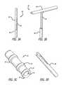
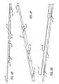
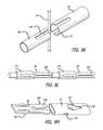
- FIG. 1is an elevation view, depicting an integrated anchor deployment device
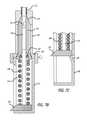
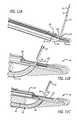
- FIG. 2Ais a cross-sectional view, depicting a distal end portion of the device of FIG. 1 ;
- FIG. 2Bis a cross-sectional view, depicting the implantation of anchoring assemblies at an interventional site
- FIG. 2Cis an enlarged view, depicting one anchoring component of the assemblies shown in FIG. 2B ;
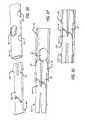
- FIG. 2Dis a partial perspective view, depicting an elongate tube assembly of the device of FIG. 1 without the outer sheath and detached from the nose assembly and handle assembly;
- FIG. 2Eis a cross-sectional view, depicting a portion of a handle assembly of the device of FIG. 1 ;
- FIG. 2Fis a cross-sectional view, depicting further details of the device of FIG. 2C in addition to a cross-sectional view of a portion of the tubular housing assembly;
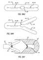
- FIG. 3Ais a perspective view, depicting a first anchoring member of an anchoring assembly of the present invention shown in a substantially straight configuration
- FIG. 3Bis a perspective view, depicting the first member of FIG. 3A in a deployed or flipped configuration
- FIG. 3Cis a perspective view, depicting a first component of a second anchoring member of an anchoring assembly of the present invention
- FIG. 3Dis a perspective view, depicting a second component of a second anchoring member of an anchoring assembly of the present invention.
- FIG. 3Eis a perspective view, depicting a connector component with a plurality of first anchoring members of the anchoring assembly disposed thereon;
- FIG. 3Fis a perspective view, depicting an assembled anchoring assembly
- FIG. 3Gis a perspective view, depicting a coined connector
- FIG. 3His a perspective view, depicting a connector equipped with raised portions
- FIG. 3Iis a perspective view, depicting a connector equipped with crimped components
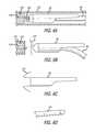
- FIG. 4Ais a perspective view, depicting an alternate embodiment of a distal component of an anchoring assembly
- FIG. 4Bis a perspective view, depicting the distal component of FIG. 4A in a flipped configuration
- FIG. 4Cis a perspective view, depicting another alternate embodiment of a distal component of an anchoring assembly
- FIG. 4Dis a perspective view, depicting the distal component of FIG. 4C in a flipped configuration
- FIG. 4Eis a perspective view, depicting yet another alternate embodiment of a distal component of an anchoring assembly
- FIG. 4Fis a perspective view, depicting the distal component of FIG. 4E in a flipped configuration
- FIG. 4Gis a perspective view, depicting a distal component of an anchoring assembly with a first embodiment of a tail section;
- FIG. 4His a perspective view, depicting a distal component of an anchoring assembly with a second embodiment of a tail section;
- FIG. 4Iis a perspective view, depicting a distal component of an anchoring assembly with a third embodiment of a tail section;
- FIG. 4Jis a perspective view, depicting yet another embodiment of a distal component
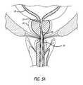
- FIG. 5Ais a cross-sectional view, depicting a first step of treating a prostate gland using the present invention
- FIG. 5Bis a cross-sectional view, depicting a portion of the anchor deployment device of FIG. 1 with the first actuator pivoted toward the handle assembly;
- FIG. 5Cis a cross-sectional view, depicting further internal mechanisms of the handle for accomplishing the advancement of the needle assembly
- FIG. 5Dis a perspective view, depicting the distal end portion of the anchor deployment device and the lateral advancement of a needle assembly
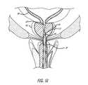
- FIG. 5Eis a cross-sectional view, depicting a second step of treating a prostate gland using the present invention.
- FIG. 5Fis a perspective view, depicting the partial retraction of the needle assembly
- FIG. 5Gis a cross-sectional view, depicting the assembly of FIG. 5D ;
- FIG. 5His a perspective view, depicting the complete retraction of the needle assembly
- FIGS. I and Jare cross-sectional views, depicting further steps of a method of treating a prostate gland using the present invention.
- FIG. 5Kis an enlarged perspective view, depicting one embodiment of a feeding mechanism for the distal component
- FIG. 6Ais an elevation view, depicting one alternative approach for controlling the advancement and deployment of an anchor component
- FIG. 6Bis an elevation view, depicting a first configuration of the anchor of FIG. 6A after release from the advancement substructure.
- FIG. 6Cis an elevation view, depicting a second configuration of the anchor of FIG. 6A after release from the advancement substructure.
- FIG. 6Dis a perspective view, depicting an alternate embodiment of a pusher device
- FIG. 6Eis a perspective view, depicting a needle and pusher assembly configured for side loading of an anchor component
- FIG. 6Fis a perspective view, depicting an alternate embodiment of a pusher assembly
- FIG. 6Gis a perspective view, depicting the pusher assembly of FIG. 6F and a complementary needle assembly
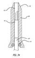
- FIG. 7Ais a cross-sectional view, depicting an anchor loaded in a protective cover
- FIG. 7Bis a cross-sectional view, depicting a pusher cartridge in a loaded position
- FIG. 7Cis a cross-sectional view, depicting the cartridge of FIG. 7A in an anchor deployed position
- FIG. 7Dis an elevation view, depicting an anchor cartridge assembly
- FIG. 7Eis a perspective view, depicting a needle assembly equipped with a sensor
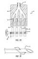
- FIG. 8Ais a cross-sectional view, depicting the pivoting of the second actuator with respect to the handle
- FIG. 8Bis an isometric view, depicting internal components operatively associated with the second actuator and with other components of the anchor deployment device removed;
- FIG. 8Cis a partial cross-sectional view, depicting a distal end portion of the integrated anchor deployment device of FIG. 8A ;
- FIG. 8Dis a partial cross-sectional view, depicting the deployment device of FIG. 8C with a second component of the second anchoring member being advanced toward a first component of the second anchoring member;
- FIG. 8Eis a perspective view, depicting the deployment device of FIG. 8B with the second component completely advanced into locking engagement with the first component;
- FIG. 9Ais an enlarged perspective view, depicting a first step in joining the first and second components of the second anchoring member
- FIG. 9Bis an enlarged perspective view, depicting a second step in joining the first and second components of the second anchoring member
- FIG. 9Cis an enlarged perspective view, depicting a third step in joining the first and second components of the second anchoring member
- FIG. 9Dis an enlarged perspective view, depicting a first step in an alternate approach in joining the first and second components of the second anchoring member
- FIG. 9Eis an enlarged perspective view, depicting a second step in the alternate approach in joining the first and second components of the second anchoring member
- FIG. 9Fis an enlarged perspective view, depicting a third step in the alternate approach in joining the first and second components of the second anchoring member;
- FIG. 9Gis a perspective view, depicting another alternate embodiment of the first and second components of the second anchoring member
- FIG. 9His a cross-sectional view, depicting an interior of the assembly shown in FIG. 9G ;
- FIG. 9Iis a perspective view, depicting yet another alternative embodiment of the first and second components of the second anchoring member
- FIG. 9Jis a perspective view, depicting yet another embodiment of the second anchoring member.
- FIG. 9Kis a perspective view, depicting a further embodiment of the second anchoring member
- FIG. 9Lis a perspective view, depicting yet a further embodiment of the second anchoring member.
- FIG. 9Mis a perspective view, depicting another embodiment of the second anchoring member.
- FIG. 9Nis a perspective view, depicting another embodiment of the second anchoring member.
- FIG. 9Ois a perspective view, depicting another embodiment of the second anchoring member.
- FIG. 9Pis a perspective view, depicting the embodiment of FIG. 9O in an assembled form
- FIG. 9Qis a perspective view, depicting another embodiment of the second anchoring member.
- FIG. 9Ris a perspective view, depicting the embodiment of FIG. 9Q in an assembled form
- FIG. 9Sis a perspective view, depicting another embodiment of the second anchoring member.
- FIG. 9Tis a perspective view, depicting another embodiment of the second anchoring member.
- FIG. 9Uis a perspective view, depicting the embodiment of FIG. 9T in an assembled form
- FIG. 9Vis a perspective view, depicting another embodiment of the second anchoring member.
- FIG. 9Wis a perspective view, depicting the embodiment of FIG. 9V in an assembled form
- FIG. 9Xis a perspective view, depicting another embodiment of the second anchoring member.
- FIG. 9Yis a perspective view, depicting another embodiment of the second anchoring member.
- FIG. 9Zis a perspective view, depicting another embodiment of the second anchoring member.
- FIG. 9 AAis a perspective view, depicting another embodiment of the second anchoring member
- FIG. 9 ABis a perspective view, depicting another embodiment of the second anchoring member
- FIG. 9 ACis a perspective view, depicting the embodiment of FIG. 9 AC in a compressed form
- FIG. 9 ADis a perspective view, depicting another embodiment of the second anchoring member.
- FIG. 9 AEis a perspective view, depicting the embodiment of FIG. 9 AD in a compressed form
- FIG. 9 AFis a perspective view, depicting another embodiment of the second anchoring member
- FIG. 9 AGis a perspective view, depicting another embodiment of the second anchoring member.
- FIG. 9 AHis a perspective view, depicting the embodiment of FIG. 9 AG in an open configuration
- FIG. 9 AIis a perspective view, depicting another embodiment of the second anchoring member in combination with a forming anvil
- FIG. 9 AJis a perspective view, depicting another embodiment of the second anchoring member in combination with a forming anvil;
- FIG. 9 AKis a perspective view, depicting another embodiment of the second anchoring member
- FIG. 9 ALis a perspective view, depicting another embodiment of the second anchoring member
- FIG. 9 AMis a perspective view, depicting the embodiment of FIG. 9 AL in an open configuration
- FIG. 9 ANis a perspective view, depicting another embodiment of the second anchoring member shown in its flattened configuration
- FIG. 9 AOis a perspective view, depicting another embodiment of the second anchoring member shown in its flattened configuration
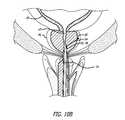
- FIGS. 10A-Bare cross-sectional views, depicting yet further steps involved in treating a prostate gland using the present invention.
- FIG. 11Ais a cross-sectional view, depicting a first step in an alternative approach to anchor assembly and deployment;
- FIG. 11Bis a cross-sectional view, depicting a second step in an alternative approach to anchor assembly and deployment;
- FIG. 11Cis a cross-sectional view, depicting a third step in an alternative approach to anchor assembly and deployment;
- FIG. 12Ais a perspective view, depicting structure configured to align components of the anchoring assembly
- FIG. 12Bis a cross-sectional view, depicting the structure of FIG. 12A ;
- FIG. 13Ais a partial cross-sectional view, depicting a first step in an alternative approach to implanting an integrated anchor assembly
- FIG. 13Bis a partial cross-sectional view, depicting a second step in an alternative approach to implanting the integrated anchor assembly of FIG. 13A ;
- FIG. 13Cis a perspective view, depicting a third step in an alternative approach to implanting the integrated anchor assembly of FIG. 13A ;
- FIG. 13Dis a perspective view, depicting yet another embodiment of an integrated anchor
- FIG. 13Eis an elevation view, depicting the anchor of FIG. 13D in a flipped configuration
- FIG. 13Fis an elevation view, depicting the anchor of FIG. 13D in a flat configuration.
- the present inventionis embodied in a device configured to deliver anchor assemblies within a patient's body.
- the present inventioncan be employed for various medical purposes including but not limited to retracting, lifting, compressing, supporting or repositioning tissues, organs, anatomical structures, grafts or other material found within a patient's body. Such tissue manipulation is intended to facilitate the treatment of diseases or disorders.
- the disclosed inventionhas applications in cosmetic or reconstruction purposes or in areas relating the development or research of medical treatments.
- one portion of an anchor assemblyis positioned and implanted against a first section of anatomy.
- a second portion of the anchor assemblyis then positioned and implanted adjacent a second section of anatomy for the purpose of retracting, lifting, compressing, supporting or repositioning the second section of anatomy with respect to the first section of anatomy.
- both a first and second portion of the anchor assemblycan be configured to accomplish the desired retracting, lifting, compressing, supporting or repositioning of anatomy due to tension supplied thereto via a connector assembly affixed to the first and second portions of the anchor assembly.
- an integrated anchor delivery device 20is configured to include structure that is capable of both gaining access to an interventional site as well as assembling and implanting an anchoring device within a patient's body.
- the devicefurther includes structure configured to receive a conventional remote viewing device so that the steps being performed at the interventional site can be observed.
- the integrated anchor delivery device 20includes a handle assembly 22 and a tubular housing assembly 24 extending from the handle assembly 22 .
- the handle assembly 22is sized and shaped to fit comfortably within an operator's hand and can be formed from conventional materials.
- the proximal end of the delivery device 20includes a mount 26 for receiving an endoscope or telescope 28 or other imaging device.
- the mount 26includes an internal bore (not shown) sized and shaped to receive the telescope 28 .
- the telescope 28is intended to provide the operator with the ability to view the operation of the delivery device 20 at an interventional site.
- the handle assembly 22 of the delivery device 20also includes a plurality of activators or triggers associated with the handle assembly 22 .
- the body 30includes a first or upper portion 32 extending generally perpendicularly with respect to a second or lower portion 34 .
- the second portionis intended to be sized and shaped to fit within the palm of an operator's hand.
- Pivotably affixed to the second portion 34is a first actuator 36 .
- the first actuator 36includes a hooped portion sized and shaped to receive one or more fingers of the operator's hand.
- the hooped portionextends from an arm which is pivotably connected to the handle 22 , the arm and hooped portion defining an acute angle with respect to the second portion 34 of the handle assembly 22 when inactivated.
- the first actuator 36is operatively associated with a needle assembly and structure configured to advance and place a first component of an anchoring assembly at an interventional site.
- a second trigger or actuator 38is pivotably connected adjacent the first body portion 32 .
- the second actuator 38defines a generally finger-like projection and is positioned longitudinally distally from the body 30 with respect to the first actuator 36 .
- the second actuator 38also defines an acute angle respecting the second portion 34 of the handle assembly 22 and is sized and shaped to comfortably receive one or more fingers of the operator.
- the second actuator 38is configured to accomplish the assembly of an anchoring device by attaching a second anchor component to a connector affixed to the first anchor component.
- a third trigger or actuator 40is connected and configured to pivotably rotate with respect to a top side of upper body portion 30 .
- the third actuator 40defines a relatively straight member with a rounded substructure formed at its free terminal end. In this way, the third actuator 40 is easily manipulated by a free digit of the operator's hand.
- the third actuator 40rotates from a forward position where it forms an acute angle with the tubular housing assembly 24 to a rearward position where the member defines an obtuse angle with respect to the tubular housing assembly 24 .
- the third actuator 40is intended to retract portions of the tubular housing assembly 24 as well as accomplish cutting the connector of the anchoring assembly and deploying the anchoring assembly at an interventional site.
- the tubular housing assembly 24extends from the handle assembly 22 .
- the tubular housing assembly 24is mounted to a front face of the upper portion 32 of the handle assembly 22 and extends parallel to a longitudinal axis of the upper portion 32 .
- the tubular housing assembly 24includes a mount 42 from which an outer sheath 44 extends in a distal direction.
- the mount 42includes one or more conventional stop cock assemblies 46 which provide fluid communication with an interior of the tubular housing assembly.
- One stop cock assembly 46is intended to provide the anchor delivery device 20 with a continuous flow irrigation.
- Another stop cock 46is contemplated to be used to accomplish a suction function through the device. Either of these assemblies can further be employed to deliver therapeutic or diagnostic substances to the interventional site.
- substances that cause the prostate to decrease in sizesuch as 5-alpha-reductase inhibitors can be introduced at the treatment site.
- Other substances but not limited thereto, which may be introduced at the siteinclude various phytochemicals, alpha-1a-adrenergic receptor blocking agents, smooth muscle relaxants and other agents that inhibit the conversion of testosterone to dihydrotestosterone.
- a terminal end portion 48 of the tubular housing assembly 24 of the anchor deployment device 20includes a nose assembly 50 shaped to provide an atraumatic surface as well as one which facilitates desired positioning of components of an anchoring assembly (See FIG. 2A ). That is, by including structure that can mimic the ultimate position of a proximally oriented component of an anchoring assembly, an operator can test the effect of the anchoring assembly prior to implantation. Once the operator confirms that the subject anchoring component will be positioned as desired, the implantation of the anchor is then undertaken and accomplished.
- the anchoring assembly 51(See FIGS. 2B and C) of the present invention accomplishes desired tissue manipulation or retraction as well as cooperates with the target anatomy to provide an atraumatic support structure.
- the shape and contour of the anchoring assembly 51can be configured so that the assembly invaginates within target tissue, such as within natural folds formed in the urethra by the opening of the urethra lumen by the anchoring assembly.
- target tissuesuch as within natural folds formed in the urethra by the opening of the urethra lumen by the anchoring assembly.
- wispy or pillowy tissue in the areacollapses around the anchor structure.
- the natural tissuecan grow over the anchor assembly 51 and new cell growth occurs over time in the areas shown in FIG. 2C .
- Such cooperation with target tissuefacilitates healing and avoids unwanted side effects such as calcification at the interventional site.
- Manners in which healing can be promotedcan include employing abrasive materials, textured sutures, biologics and drugs.
- the terminal end portion 48( FIG. 2A ) includes a plurality of spring biased, vertically stacked ring anchor components 52 strategically positioned with respect to telescoping structure of the tubular housing assembly for the purpose of assembling an anchoring device.
- the stacked anchor component 52is one of two parts which form a second anchor component.
- a leaf spring 54is placed in apposition with the anchor component 52 that is at the bottom of the stack of components.
- Internal molded walls and bosses of the nose assembly 48form a space to both receive the stacked anchor components 52 as well as provide an area to retain the leaf spring 54 and provide a base structure against which force supplied by the leaf spring can be generated and transmitted to the anchor components 52 .
- FIG. 2Aterminal end portions of an upper tubular member 56 , a needle housing 58 and a telescope housing 60 are positioned within the nose assembly.
- FIG. 2Done can better see the internal components forming the tubular housing assembly.
- the outer sheath 44is not depicted in FIG. 2A and the internal components of the tubular housing assembly are shown separate from the nose assembly and handle assembly.
- the upper tubular member 56 , the needle housing 58 and telescope housing 60extend longitudinally.
- the outer sheath(not shown in FIG. 2A ) covers a substantial length of each of the upper tubular member 56 , needle housing 58 and telescope housing 60 .
- Each of these structuresalso include internal bores, the upper tubular member 56 sized to slideably receive a pusher assembly (described in more detail below) and the needle housing 58 sized to slideably receive a needle assembly 58 (also described in more detail below).
- the telescope housing 60is sized to receive a conventional telescope (not shown), which in one approach, fills the entire space provided by the internal bore of the housing 60 .
- a cross-sectional view of a portion of the tubular housing assembly attached to the handle assembly 22 (with the nose assembly removed)is shown in FIG. 2F .
- the handle assembly 22houses a needle assembly advancement and retraction subassembly 66 that interacts with the movement of the first actuator.
- the first actuatorincludes a projection 68 extending through the housing assembly 22 and is placed in operative association with the advancement and retraction subassembly 66 .
- the needle assembly advancement and retraction subassembly 66includes an outer collar 70 configured about an inner collar 72 . Configured between the outer collar 70 and an internal front surface 74 of the handle assembly 22 is a first compressor spring 75 . Placed within the outer collar 68 and between the inner collar 72 and an internal front surface 76 is a second compression spring 77 . Additionally, attached to the outer collar 70 is a lock assembly 78 which rotates between locked and unlocked positions.
- the compression springs 75 , 76assume expanded configurations (See FIGS. 2E and F). Also, the lock assembly 78 is in a disengaged or unlocked configuration. It is at this stage that the needle assembly (described below) is in its retracted state and housed completely within the needle housing 58 .
- FIGS. 3A and 3BOne preferred embodiment of a first or distal component 82 is shown in FIGS. 3A and 3B .
- the first componentforms a generally T-configuration ( FIG. 3B ).
- the first componentdefines a substantially straight member ( FIG. 3A ).
- the componentcan be formed from a number of materials and manufactured using various conventional approaches, it is contemplated that the component 82 be cut from a nitinol tube using a laser. Using a superelastic material such as nitinol provides the component 82 with the resiliency to transform between a flipped T-configuration and a straight configuration.
- the first component 82includes a first portion 84 which at one end defines a cylindrical structure and at the other a partial cylindrical structure. When unconstrained, this first portion 84 forms a T-bar or top of the first component 82 .
- a complementary partial cylindrical structureforms a mid-section or second portion 86 of the first component 82 and operates as a spring to accomplish the flipping of the first portion 84 between constrained and unconstrained configurations. When the component is in its constrained, straight form, the second portion is positioned adjacent the first portion 84 .
- a third portion 88is also cylindrical in shape and extends from the second portion 86 away from the first portion 84 of the first anchor component 82 . The third portion 88 slides freely with respect to a connector, the connector being attached to the first portion 84 and a second anchor component as will be described below.
- FIG. 3COne part of the second anchoring component 52 is best seen in FIG. 3C (previously depicted as stacked anchor components in FIG. 2A ).
- This componentis generally cylindrical in form and includes integrally formed rings 90 spaced along an outer surface of the device, such spacing can be varied as necessary for a particular purpose.
- the devicefurther includes a internal bore 92 which extends the entire length thereof.
- a proximal end 93 of this part of the second anchoring component 52includes an opening to the internal bore 92 .
- the opening to the bore 92is surrounded by a first ring 90 and is sized to receive in a locking arrangement the connector which will attach the first anchor 82 to the second anchor component 52 .
- Additional rings 90are spaced longitudinally along an outside surface of the component.
- a second part 98 of the second anchoring component 52can be sized and shaped to both engage a connector and to lockingly engage the first part.
- the second partis generally cylindrical and includes a pair of spaced arms, the outer profile being sized to fit within the internal bore 92 of the first part.
- the connector 94can be formed from any material which provides the desired holding force between first and second components.
- the connectoris formed from conventional suture material for example monofilament polyester.
- the connector 94is monofilament polyethylene terephthalate (PET).
- PETpolyethylene terephthalate
- the suture materialembodies desirable flexibility as well as tensile strength.
- the monofilament PET size 2-0is preferred because of high tensile strength when tensioned and high column strength to push the series of parts 82 through and out the needle.
- the monofilamenthelps reduce or eliminate the possibility of infection.
- first anchor components 82can be affixed along a length of the connector 94 .
- various approachescan be employed to attach a first anchor component 82 to the connector.
- the componentscan be affixed by an adhesive or can include tabs or other structure which is deformed into a locking arrangement with the connector 94 .
- the anchor component 82can simply be crimped directly to the connector 94 or the connector itself can include structure which is complementary to that of the component to accomplish affixation. It may be advantageous to employ an assembly capable of handling a connector equipped with a plurality of anchor components spaced along the connector since such a system has the ability to assemble and deliver multiple anchor assemblies without needing to reload.
- FIG. 3FOne embodiment of a completely assembled anchoring assembly 92 is depicted in FIG. 3F .
- the assemblyincludes a single first anchor component 82 .
- the completed anchor assemblyis formed from components which are held together magnetically.
- the first anchor component 82 and the second anchor component 52 , 98can be held in place through magnetism and without the need of a connector.
- either both or one of the anchor componentscan be a magnet.
- the second anchor componentembodies the first part 52 which can be deployed from the stacked group of such members housed within the terminal end portion 48 of the tubular housing assembly 24 (See FIG. 2A ), as well as the second part 98 which, by operation of the anchor delivery device 20 (described below), lockingly engages the first part 52 .
- a completed anchor assembly 96can be employed to manipulate tissue and other structure found within a patient's body for various purposes.
- the first anchoring component 82is initially positioned in an apposition with a first body structure, such as the outer surface of the prostate capsule, and the second anchoring component assembly ( 52 , 98 ) is placed against a second body structure, such as the inner surface of the urethra, the connector 94 holding the desired spacing between the two body structures to accomplish the desired manipulation.
- all components of the anchor assembly 96 or selected portions thereofmay be coated or embedded with therapeutic or diagnostic substances (e.g. drugs or therapeutic agents).
- therapeutic or diagnostic substancese.g. drugs or therapeutic agents.
- the anchor assembly 96can be coated or imbedded with substances such as 5-alpha-reductase which cause the prostate to decrease in size.
- substances contemplatedinclude but are not limited to phytochemicals generally, alpha-1a-adrenergic receptor blocking agents, smooth muscle relaxants, and agents that inhibit the conversion of testosterone to dihydrotestosterone.
- the connector 95can for example, be coated with a polymer matrix or gel coating which retains the therapeutic or diagnostic substance and facilitates accomplishing the timed release thereof.
- bacteriostatic coatingscan be applied to various portions of the anchoring assemblies described herein. Such coatings can have various thicknesses or a specific thickness such that it along with the connector itself matches the profile of a cylindrical portion of an anchor member affixed to the connector.
- the co-delivery of a therapeutic or diagnostic gel or other substances through the implant deployment device or another medical device (i.e. catheter), and moreover an anchor assembly including the sameis contemplated.
- the deployment deviceincludes a reservoir holding the gel substance and through which an anchoring device can be advance to pick up a desired quantity of therapeutic or diagnostic gel substance.
- the connector 94can have associated therewith various structures which facilitate the attachment of anchoring structures. Although intended for the first anchor component 82 , such structure can also be used for the second anchor component 52 , 98 . In one approach ( FIG. 3G ), the connector 94 is coined 100 in a manner that provides structure to which an anchor member can form a locking engagement. As shown in FIG. 3H , structure facilitating a locking engagement with anchor structure also can also be in the form of a ball-chain 102 . Furthermore, a connector 94 can be equipped with crimped metal or other structures 104 for this purpose.
- FIGS. 4A-4Ivarious alternatives of first anchor components 82 are presented.
- those depicted in FIGS. 4A-Ieach include a structure which flips to assume an angled or generally lateral configuration when the component is unconstrained. In a constrained configuration, these components define a generally cylindrical profile (as shown in FIG. 4A ).
- each of the various alternative embodimentscan be formed from conventional materials.
- the componentscan be formed by laser cutting a nitinol tube.
- EDMelectrospray diffraction
- the connector shown in FIG. 4Aincludes a proximally oriented collar 106 which is intended to be slid along a connector as the second portion flips or rotates.
- a spring member 86defines a bar arm which forms a bridge between the collar 106 and a second portion 108 which flips or rotates with respect to the collar 106 when the device is unconstrained as shown in FIG. 4B .
- the spring member 86forms a bridge between the collar 106 and a second portion 108 which includes a pair of members which in a constrained configuration extend in opposite directions along the connector 94 and when unconstrained, form a T-bar structure.
- FIGS. 4C and 4Dthe spring member 86 forms a bridge between the collar 106 and a second portion 108 which includes a pair of members which in a constrained configuration extend in opposite directions along the connector 94 and when unconstrained, form a T-bar structure.
- the anchoring component 82can include a pair of collars 106 configured between which are first and second springs 86 . Attached to each spring 86 is a second portion 108 , each of which assume angled or lateral positions to thereby form an overall cross-like structure when unconstrained. Like the other embodiments, the component defines a generally straight, cylindrical structure when constrained.
- FIGS. 4G-Idepict further embodiments of structures that can be employed as first anchoring components 82 or alternatively, can be used solely as structures for advancing the anchoring assembly sub-components within the anchor delivery device or a patient's body.
- Each of these depicted structuresinclude various forms of tails 110 which can be employed to advance the anchor components 82 through direct engagement with a terminal end of a pusher assembly (not shown) or for registering within slots formed in a pusher assembly. These tails also help to flip, turn or angle the component 82 relative to connector 94 .
- One embodiment of the tail( FIG. 4G ) is a simple extension of a partial cylindrical member which is bent away from the connector 94 . Another approach ( FIG.
- FIG. 4Hinvolves a long tail 110 which is folded against the connector 94 and yet another approach ( FIG. 4I ) involves a tail 110 that rather than folded against the connector includes a narrowed section which is bent away from the connector and terminates to assume a beaver tail-like shape.
- the first anchoring componentincludes a full tube portion 107 connected to a half tube portion 109 by a coiled portion 111 .
- the devicecan further include suture attachment points formed along the full tube portion 109 .
- the coiled portion 111provides flexibility in multiple planes and thus facilitates pushing the device through bends or angles formed in the deployment device employed to deliver the first anchoring component 82 .
- the telescope deviceis employed to view the positioning of the device 20 at the interventional site, for example, the tubular housing assembly 24 of the device is inserted into the penis of a patient and advanced until the distal end 48 is adjacent an interventional site in the urethra (UT) adjacent the bladder (UB; See FIG. 5A ).
- UTurethra
- Uurethra
- the present inventionalso contemplates steps for sizing the anatomy.
- the present inventionalso involves the placement of an ultrasonic or other device in the patient's body, such as in the rectum, to measure the necessary depth of insertion of the anchor deployment device within the patient's body.
- This informationcan be used to set or create a depth stop for the needle assembly so that the operator can readily determine whether desired sections of the patient's anatomy have been accessed.
- the first actuator 36 of the delivery device 20See FIG. 1
- the handle assembly 22is then caused to be pivoted towards the handle assembly 22 . Doing so causes the needle assembly 112 to be advanced distally and then laterally through a terminal end of the needle housing 58 .
- the lock assembly 78retains the needle in the advanced configuration (See FIGS. 5C and D).
- the lock assembly 78can be configured to automatically unlock or to require manipulation to disengage from a locking position.
- the needle assembly 112is advanced through the prostate gland to a first implant position (See FIG. 5E ).
- first forked member 113is translatable longitudinally either by hand or through action of a trigger or activator.
- FIG. 5Dthe first forked member 113 is shown retracted to more easily represent other system components, but in use, at this stage of deployment, the member 113 is contemplated to be in an advanced position into engagement with slot 115 .
- second forked member 119is shown in a truncated form, in that at this stage of deployment the terminal end of the member 119 extends beyond the vertical stack of second anchor components 52 , thereby holding the stack in a staged configuration.
- the present inventionalso contemplates a single member replacing the forked members 113 , 119 depicted, such a part of member 56 which can have portions which provide the function accomplish by the terminal ends of the members 113 , 119 .
- the needle assembly 112has a generally tubular shape and terminates with a sharp point 114 .
- a lumen extending the length of the needle assembly 112is sized to receive both components of the anchoring assembly as well as structure for advancing the assembly through and out of the terminal end 114 .
- the needle assembly 112is intended to be formed from resilient material such as nitinol or other materials or polymeric substances.
- the needle housing 58includes a distal section angled such that the needle projects at angles approaching or at 90 degrees with respect to a longitudinal axis of the tubular housing assembly 24 .
- the actuatoris further manipulated to release the lock assembly 78 as well as to cause the internal compression springs to retract the needle assembly.
- the position of the first actuator 36will return to the open position (See FIGS. 1 , 2 E and 2 F).
- the result of this actionis depicted in FIGS. 5F , G, H, I and J. (Again, note that member 113 and 119 are shown in retracted or truncated forms in FIGS.
- the advancing structureis in the form of a pusher assembly 116 .
- the pusher 116can assume a generally cylindrical tube formed form a metallic or polymeric material which is sized and shaped to directly engage the first anchoring component 82 .
- the pusher 116could define a solid elongate member of polygonal or circular cross-section. Also, it can be configured to directly engage the connector 94 directly or other structure formed on the connector 94 (See FIGS. 3G-I ).
- the pushercan be sized to surround the first anchor member 82 and to engage a tail (See FIGS. 4G-I ) for example, of the anchor member once the pusher is pulled proximally with respect to the anchor member.
- a tailSee FIGS. 4G-I
- the pusher 116initially surrounds the anchor member (or other structure formed directly on the connector 94 )
- the tailis held in compression, only to be released to extend laterally from the connector when the pusher is moved proximally.
- the pusher assembly 116can both be withdrawn when desired and advance the anchor member 82 and connector structure 94 when necessary.
- the tailcan be held in compression by the internal surface of the needle (not shown).
- the complete withdrawal of the pusher 116 and needle assembly 112exposes the full length of connector anchoring structure for use in ultimately manipulating anatomical structures.
- Such complete withdrawalinvolves both the pusher 116 and needle assembly to be housed completely within the needle housing 58 .
- the delivery devicecan be equipped with a pusher member 116 in combination with a pull wire 118 .
- the pusher member 116 in this approachremains proximal an anchor member 82 to be advanced along the delivery device.
- Such anchor members 82can be placed in a position distal the pusher, for example, by being released from a cartridge configured distal to the pusher position or the delivery device can be a single use apparatus.
- the anchor member 82can include a proximal portion characterized by a pair of elastically or plastically deformable arms 120 which in a first configuration are held to the pull wire 118 and in a second configuration, are released from the pull wire 118 . Accordingly, the pusher member 116 is advanced with respect to the pull wires 118 to cause the arms 120 to become disengaged from the pull wire.
- the arms 120are plastically deformable whereas the arms 120 of the anchor member 82 of FIG. 6C are elastically deformable.
- the elastically deformable arms 120can be formed from resilient material such as nitinol.
- the plastically deformable arms 120on the other hand can be made from less resilient material.
- FIGS. 6D-GFurther alternative embodiments of pusher members 116 are shown in FIGS. 6D-G .
- a pusher member 118 having a D-shaped cross-sectional profileis contemplated for certain uses. Such a profile enables the pusher member 116 to be placed along side the anchor component 82 and connector 94 assembly, a distal portion of the D-shaped configuration engaging complementary structure on the connector assembly.
- a pusher assembly 116which includes a side opening 122 in communication with a lumen extending through the pusher 116 (See FIG. 6E ). Threaded through the side opening 122 is a distal portion of the anchor component 82 and connector 94 assembly. In this arrangement, the distal-most anchor component 82 is placed against the terminal end of the pusher member 116 to accomplish advancement of the anchor component 82 and connector 116 assembly as the pusher 116 is extended distally.
- the pusher member 116includes a terminal end 123 configured with a D-shaped profile suited to engage and advance an anchor/connector assembly 94 .
- a proximal section of the pusher 116is equipped with a plurality of spaced detents or cavities 124 sized and shaped to receive anchor components 82 or other structure formed on the connector 94 .
- the pusher member 116is configured to reside longitudinally adjacent the anchor/connector assembly 82 , 94 . Advancement of the anchor/connector assembly 82 , 94 is accomplished through an engagement between certain of the anchor/connector assemblies 82 , 94 and the cavities 124 .
- a first stepthe anchor member 82 is loaded within an anchor protection cover 126 ( FIG. 7A ).
- a pusher member 116is configured proximal to the connector 94 of the first anchor member 82 to accomplish advancement of the first anchor member 82 into and through the needle assembly 112 (See FIGS. 7B and C).
- This subassemblyis insertable within a delivery device bay 128 .
- a distal portion 130 of an interior of the delivery device bayis equipped with a conical taper configured to receive a distal complementary portion of the anchor protection cover 126 thereby accomplishing the centering of anchor member within the delivery bay 128 .
- An internal lumenextends the length of the protection cover 126 and the cover 126 includes a ring seal 132 placed within a proximal end thereof. The ring seal 132 functions to hold the cover 126 on a pusher member 116 .
- the delivery device bay 128can further include a bayonet lock mount 134 that couples a spring loaded cartridge 136 to the delivery device bay 128 .
- a compression spring 138housed within the cartridge is a compression spring 138 configured about the pusher member 116 .
- the spring cartridge 138can also include a lock-out structure 140 which operates to limit the tension placed on the anchor member 82 and connector 94 until the needle 112 is withdrawn sufficiently from the interventional site to avoid damage from the needle 112 inadvertently engaging the anchor/connector assembly 82 , 94 .
- the pusher 116includes a proximal end configured with an anchor deployment tab 142 that engages the lock-out structure 140 , prohibiting the compression spring 138 from applying tension to the anchor/connector assembly 82 , 94 before the needle assembly 112 is clear of the interventional site.
- the anchor delivery devicecan be fashioned with a multi-shooter anchor cartridge assembly 144 .
- a manifold 146including four entries which feed into a lumen extending into a needle assembly 112 , each entry configured to receive one anchor/connector assembly 82 , 94 .
- Proximal sections of the connector 94are configured into spools 148 which are driven by a torsional spring drive shaft 150 .
- the drive shaft 150is in turn, configured with complementary teeth structures 154 formed on each spool.
- the assemblyfurther includes structure (not shown) adapted to cause lateral movement in the driveshaft 150 so that its teeth 152 indexes from spool to spool 148 to thereby turn the spools 148 and advance the anchor members 82 within the needle assembly 112 .
- structure(not shown) adapted to cause lateral movement in the driveshaft 150 so that its teeth 152 indexes from spool to spool 148 to thereby turn the spools 148 and advance the anchor members 82 within the needle assembly 112 .
- the anchor delivery devicecan include the ability to detect forces being applied thereby or other environmental conditions.
- sensors 156can be placed along the needle assembly 112 . In this way, an operator can detect for example, whether the needle has breached the target anatomical structure at the interventional site and the extent to which such breaching has occurred.
- Other sensors which can detect particular environmental featurescan also be employed such as blood or other chemical or constituent sensors.
- one or more pressure sensors or sensors providing feedback on the state of deployment of the anchor assembly during delivery or after implantationare contemplated. For example, tension or depth feedback can be monitored by these sensors. Further, such sensors can be incorporated into the anchor assembly itself, other structure of the deployment device or in the anatomy.
- FIG. 8Bwhich depicts internal components of the integrated anchor assembly associated with the second actuator (other structure being removed for better understanding), as the second actuator 36 is depressed, it engages a lever assembly 120 including a slotted portion 122 to drive a rack assembly 124 distally.
- the slotted portion 122 of the lever assembly 120provides the lever with the ability to both rotate with respect to a mount 126 of the rack assembly 124 as well as advance the mount 126 as well as the rest of the rack assembly 124 distally.
- Various pawls 130are provided to releasably lock the rack assembly 124 in desired stages of advancement. It is to be recognized, however, that various other approaches to manually locking or unlocking structure for advancing components of the second anchor assembly are contemplated.
- the rack assembly 124is in turn, connected to a telescoping pusher member which is configured to engage a second part o the second or proximal anchor assembly.
- depressing the second actuator 38causes a pusher 157 to advance a second part 98 of the second or proximal anchor member to be advanced towards and into locking engagement with the first part 52 of the second anchor member.
- the second part 98captures the connector structure 94 and retains it in a locking engagement between the first 52 and second 98 parts.
- the connector 94is severed to thereby accomplish the formation of the complete anchoring assembly (See FIG. 3E ).
- the severingcan be effected by the advancement of the telescoping pusher member via the depression of the second actuator 38 .
- the severing actionis operatively associated with the actuation of the third actuator 40 .
- the second actuator 38is released, automatically or manually, to permit the re-staging of both the first 52 and second 98 parts of the second anchoring member. That is, in one contemplated approach, members 113 and 119 are withdrawn to allow the release and deployment of the second anchoring member 52 , 98 and then advanced again after the desired staging of component 52 .
- the present inventionalso contemplates a myriad of alternative embodiments of the proximal or second anchoring member.
- the second anchoring memberis comprised of a first part 52 which is placed into a locking engagement with a second part 98 .
- the first 52 and second parts 98are affixed to the connector 94 .
- the first and second partscan be formed of any conventional materials such as metals or polymeric materials.
- the second anchoring memberincludes a generally tubular first part 52 including a slightly flared mouth configured to receive both a portion of the connector 94 and a second part 98 .
- the second partincludes a pair of spaced arms 158 which capture the connector and facilitates advancing the connector within the mouth of the first part. It is contemplated that the arms 158 are spaced to an extent greater than an interior of the tubular first part 52 so that in combination with the area occupied by the connector 94 , a locking engagement between the first and second parts is accomplished upon the full insertion of the second part 98 within the first part 52 . Thereafter, excess connector 94 length can be cut away to form a complete second anchoring assembly.
- the second part 98includes a spike-like terminal end portion 160 which can be configured to engage the connector 94 and insert it within an interior of a tubular first part 52 .
- the spike-like terminal end portion 160defines a tapered structure, a section with an enlarging dimension of which is sized and shaped to lockingly engage with the interior of the first part 52 .
- the completed assemblyis characterized by a portion of the connector 94 retained between the first 52 and second parts 98 .
- the connector 94is arranged to be threaded through a pair of oppositely arranged apertures 162 formed in a generally tubular first part 52 .
- the first part 52further includes a mouth equipped with a plurality of proximally oriented, radially spaced arms 164 .
- the second part 98also defines a generally tubular structure, one having a section with a smaller outer profile than an interior of the first part 52 .
- the second part 98further includes a pair of distally oriented projections 166 as well as a back end equipped with a gear-like collar 168 .
- the second part 98is inserted within the first part 52 so that the projections 166 are configured on opposite sides of the connector.
- the collar 168is then used to rotate the second part 98 with respect to the first part until the connector 94 defines an S-shaped portion within an interior of the first part.
- the second part 98is thereafter fully inserted into the first part, the gear-like collar being configured to register between the radially spaced arms 164 of the first part 52 to thereby lock the two parts to each other.
- these structures of the first 52 and second 98 partscan be reversed in that the first part 52 can assume the structure of the described second part and vice versa.
- FIGS. 9I and Jtake a similar approach to that shown in FIGS. 9G and H. That is, each take advantage of a locking engagement resulting from the rotation of one part of the second anchoring member with respect to the other.
- each of these embodimentsinclude a first part 52 with pair of apertures 162 through which a connector 94 is threaded.
- the assembly depicted in FIG. 9Iincludes a first part 52 configured with internal threads 168 which are complementary to external threads 170 formed on a second part 98 .
- the complementary threaded portionsforming the locking engagement between the two parts.
- 9Jtakes advantage of a second part 98 including arms 166 which are bent radially outwardly and the bent portion being sized to facilitate a locking arrangement with an interior of the first part 52 .
- This particular approachis also characterized by the first 52 and second 98 parts having rounded terminal ends which provide an atraumatic surface which can be desirable in certain situations.
- the structures of the first and second partscan be reversed if desired as can those of the following approaches.
- FIG. 9Kanother approach involves a first part 52 including a pair of proximally oriented projections 172 which can be formed by splitting longitudinally the mouth to the generally tubular first part 52 .
- the connector 94is captured between the distally oriented spaced projections 166 of the second part 98 and the proximally oriented projections 172 of the first part 52 as the second part 98 is inserted within the first part 52 .
- the second part 98is pre-loaded with a lock ring 174 , which is oriented about the second part 98 at a proximal end portion thereof.
- a lock ring 174is then advanced over the second part 98 to accomplish a locking arrangement.
- the first part 52can also define a generally tubular member having an oval cross-sectional profile. Such a structure is depicted in FIGS. 9M and N. Further, one of the oppositely oriented apertures 162 formed in the first part 52 can further include a slotted-portion 172 sized to receive a portion of a connector after the first part 52 is placed in a locking arrangement with the second part 98 .
- the first part 52further includes a pair of openings 178 configured on opposite lateral sides of the device.
- the second part 98defines a relatively flat member, the distally oriented arms 166 of which include projections 180 having a ramped portion.
- both embodiments of the second part 98further include a second pair of projections 182 formed at proximal end portions of the respective devices.
- the first projections 180act to compress the arms together then are advanced past the lateral apertures 178 of the first part 52 and are configured beyond a distal end (not shown) of the first part 52 .
- the second pair of projections 182register within the lateral openings 178 formed in the first part 52 , thus forming a locking engagement.
- the first part 52can also be formed form a member having a deformable, enlarged mid-section 184 (See FIGS. 9O and P).
- the enlarged mid-section 184can be formed by longitudinally cutting a portion of the first part 52 and separating the material forming this portion to define the opening 162 which is as before, intended to receive a portion of the connector.
- the second part 98 in the form of a generally tubular sleeveis advanced over the first part 52 , the mid-section 184 is compressed, such compression effecting a locking engagement between the first and second parts.
- the second part 98can also include laterally spaced tabs 180 which slide within an interior of a generally tubular first part 52 .
- the spaced areas 166capture a portion of the connector 94 .
- the laterally spaced tabslock in place outside a proximal end of the first part 52 .
- the portion of the connector 94 captured by the arms 166is compressed and held in place between the first 52 and second parts 98 .
- FIGS. 9S-Ufurther approaches to accomplishing a locking arrangement between first 52 and second 98 parts are presented.
- the embodiment of FIG. 9Sis characterized by a first part having a generally oval cross-sectional profile and including both the first lateral apertures 178 as well as a pair of oppositely oriented, second lateral apertures 186 .
- the second partis a generally flat member characterized by a proximal end configured with a stop in the form of a T-bar 184 .
- the tabs 180 formed on the second partfirst register within the first lateral openings 178 .
- the second partis further inserted within the first part 52 to capture the connector which is threaded through the apertures 162 formed in the first part 52 .
- Yet further advancement of the second part 98configure the detents 180 within the second lateral openings 186 of the first part 52 .
- the proximal stop 188is at this time placed in apposition with a proximal end of the first part.
- the generally flat second part 98includes both the first 180 and second 182 tab structures.
- the first tabs 180initially register within lateral openings 178 of the first part 52 , which can act as a staging for subsequent advancement and capture of a connector.
- the first tabs 180are held within an interior of the first part 52 and the second tabs 182 register within the lateral openings 178 of the first part 52 .
- the first part 52can also assume a pin-like structure with spaced arms 190 .
- the second part 98can define a generally tubular structure including distally oriented arms 166 . Insertion of the first part 52 within the second part 98 causes the spaced arms 190 of the first part 52 to compress about a portion of a connector to form a locking arrangement. It is to be recognized that this approach to a locking arrangement can be modified in principle, in that, as stated above, the structures of the first 52 and second 98 parts can be reversed.
- the second part 98can assume a generally tubular structure including a cutting projection 192 (See FIG. 9X ) arranged to engage a connector 94 upon insertion of the first part 52 within the second part 98 .
- a cutting projection 192See FIG. 9X
- the structures of the first 52 and second 98 partscan be reversed to also take advantage of this approach.
- the second anchoring componentcan be formed of a single integral locking member 194 .
- Certain of these members 194are intended to be formed of plastically deformable material so that it can first assume a generally open configuration and then be deformed to define a closed position in a locking arrangement about a connector member.
- these members 194can be formed of resilient material and be first held open and then allowed to self-collapse about a connector.
- the integral member 194is generally V-shaped and includes a pair of diverging arms 198 which can be arranged into locking contact with a connector 194 .
- Another locking member 194FIG.
- the locking member 194 of FIG. 9 AAis also generally V-shaped and further includes a pair of diverging arms 196 , one of which includes bosses 198 designed to mate with recesses 200 .
- a center section of one arm 196is bent to provide space to receive a connector.
- FIGS. 9 AB-ACthere is shown a plastically deformable locking member 194 that is configured with a collapsible aperture 202 .
- the aperture 202is formed by walls defining a generally hour glass shape. Applying a longitudinal compression force to the locking member 194 causes the aperture 202 to collapse about and lock with a portion of a connector 94 , the walls deforming inwardly and engaging the connector 94 .
- the locking member 194can also be embodied in a device including a mid-section characterized by helically arranged members 204 (See FIGS. 9 AD-AE).
- the opening 202 defined by the helical member 204is sized to receive a connector member.
- This devicecan either be formed of plastically or elastically deformable materials such that collapsing the opening 202 about a connector can be accomplished through the application of a force to the locking member 194 or by removing a compression force from the member.
- the locking member 194can be embodied in a member including diverging arms 196 projecting from a cylindrical base 204 .
- One armincludes a boss or raised portion 198 sized to fit within a recess 200 .
- a mid-section of the devicefurther includes a generally circular space 206 defined by semi-circular cutouts formed in the opposing arms 196 . This space is sized to lockingly engage a connector when the arms 196 are in a closed configuration.
- the locking member 194 of FIGS. 9 AG-AHalso includes this circular space 206 defined by semi-circular cutouts formed in the diverging opposing arms 196 as well as the locking projections 198 .
- the arms 196 and the locking member 194extend proximally beyond the circular space 206 .
- This portion of the arms 196also include a complementary projection 198 and recess 200 arrangement.
- the locking member 194can be deformed about a connector 94 employing an anvil 210 .
- anvil custom designed for the various approachescan be employed to deform the previous disclosed embodiments of other members.
- angled surfaces within an interior of the anviloperate to close the arms 196 of the locking member 194 .
- Narrowed portions 212 of the locking memberfacilitate such closing of the arms about a portion of the connector 94 .
- a cutting blade 216severs the connector 94 to length as desired.
- FIGS. 9 AJ-Kfurther embodiments of a second anchoring member including a first part 52 and a second part 98 are presented.
- the second part 98includes arms 196 which are biased to an open configuration. Using an anvil 210 housing a first part 52 in the interior cavity 214 , the second part 98 is caused to be inserted and held within the first part 52 .
- the arms 196 of the second part 98are relatively long compared to those of a second embodiment (FIG. 9 AK).
- a generally tubular first part 52retains the arms 196 in a closed position in locking engagement about the connector 94 .
- a pair of arms 196begin at a proximal end of the device in a spaced arrangement. As the arms extend distally, they cross at mid-point 218 beyond which a distal portion of the arms are adjacently arranged in apposition.
- One or both arms 196can include a recess providing a space to allow the arms 196 to cross at the mid-point 218 . Applying a force to the proximal, spaced portion of the arms 196 causes the distal portion of the arms 196 to open. When opened, the arms 196 can be configured to receive a connector. A closing force between the distal portion of the arms 196 of the locking member 194 accomplish locking the structure on a connector.
- the first part 52 of the second anchoring membercan also be configured from a flat sheet of material into which a pattern is cut to form various slots and tabs (See FIGS. 9 AN-AO).
- These first parts 52can be formed of material which is capable of self-forming from the flat configuration into a generally tubular configuration when unconstrained. For example, material such as nitinol which has memory properties can be used to form such structure.
- a first contemplated flat pattern(See FIG. 9 AN) includes a central five sided aperture 222 on either side of which are configured slots 224 cut in from lateral side edges of the structure. In a second pattern (FIG. 9 AO), the lateral slots 222 are replaced with cutouts which define tabs 226 .
- a next step in the context of prostate treatmentinvolves positioning the proximal anchor assembly 52 , for example, within a desired section of the urethra (UT) of the patient (See FIG. 10A ). Prior to doing so, the patient can be monitored to determine whether there has been any evidence of improvement through the placement of the anchor. One such symptom is whether there has been any urination. After so checking, the proximal anchor assembly 52 can be implanted. The patient is the again checked for evidence of improvement (i.e., flow improvement, visual appearance, opening of the urethra, urination, etc.). Next, the connector 94 is severed and the integrated anchor delivery device is withdrawn (See FIG. 10B ) and ultimately removed from the patient's body.
- evidence of improvementi.e., flow improvement, visual appearance, opening of the urethra, urination, etc.
- the present inventioncontemplates both pushing directly on anchor portions of an anchoring assembly as well as pushing directly upon the connector of the anchor assembly.
- the distal or first anchoring componentis advanced and deployed through a needle assembly and at least one component of the proximal or second anchoring component is advanced and deployed through a generally tubular potion of the anchor deployment device.
- both a single anchor assembly or multiple anchor assembliescan be delivered and deployed at an intervention site by the deployment device. Consequently, in the context of prostate treatment, the present invention accomplishes the compression of both the urethra and prostate gland, the delivering of an implant at the interventional site, applying tension between ends of the implant, and the invagination of the implant within natural tissue.
- drug deliveryis both contemplated and described as a further remedy in BPH in treatment.
- FIGS. 11A-CAn alternate embodiment of a distal portion of an anchor delivery device is shown in FIGS. 11A-C .
- FIG. 11Adepicts the device in a stage of operation where the needle assembly 112 has been extended through the needle housing 60 and configured to project laterally from a distal end portion 48 of the device and is in the process of being withdrawn over the connector 94 and first anchor member 82 assembly.
- FIG. 11Bshows the position of the pusher assembly 116 once the needle assembly has been fully retracted within the needle housing 58 .
- a retractable cover 228 shown in its advanced positionincludes a side aperture 230 through which the needle 112 and pusher 116 assemblies can be advanced to thereby place the connector 94 in a position for engagement by first and second 98 parts of the second anchoring member.
- a sliding arm 232is provided and placed into engagement with the cover.
- the sliding arm 232is operatively associated with an actuator (not shown) pivotably attached to a device handle.
- the connector 94is severed and equipped at its proximal end with one embodiment of a second anchoring member assembly.
- the delivery devicecan be equipped with an alignment tube 234 including inwardly directed tabs 236 sized and shaped to be received into complementary recesses formed in second parts 98 of a second or proximal anchoring assembly.
- Such tabs 230not only provide structure for advancing the second parts 98 but it also ensures proper rotational alignment of the second part 98 as they are advanced to receive a portion of the connector and to lockingly engage with a first part of the second anchoring assembly.
- an integrated anchor 240 including a plurality of anchors 82 attached to each other by a connector 94can also be used to manipulate anatomical structures.
- a needle assembly 112is utilized in a sewing motion to place various portions of the integrated anchor 240 on opposite sides of anatomical structures to accomplish the desired manipulation at an interventional site.
- the integrated anchor 240can also be cut from a pattern ( FIG. 13F ) to form a device which can assume a generally straight tubular configuration ( FIG. 13D ) for delivery to an interventional site.
- the devicecan be permitted to deform a generally H-shape ( FIG. 13E ), a first portion 252 being placed in apposition with a first anatomical structure and a second portion 254 configured against a second anatomical structure.
- a mid-section of the devicecan include a spring-like structure 256 which is particularly suited for applying a tension to the first 252 and second 254 portions.
- one or more componentssuch as distal anchor, proximal anchor, connector, of the one or more anchoring devices disclosed herein may be designed to be completely or partially biodegradable or biofragmentable.
- the devices and methods disclosed hereinmay be used to treat a variety of pathologies in a variety of tubular organs or organs comprising a cavity or a wall.
- organsinclude, but are not limited to urethra, bowel, stomach, esophagus, trachea, bronchii, bronchial passageways, veins (e.g. for treating varicose veins or valvular insufficiency), arteries, lymphatic vessels, ureters, bladder, cardiac atria or ventricles, uterus, fallopian tubes, etc.
Landscapes
- Health & Medical Sciences (AREA)
- Life Sciences & Earth Sciences (AREA)
- Surgery (AREA)
- Veterinary Medicine (AREA)
- Animal Behavior & Ethology (AREA)
- Public Health (AREA)
- General Health & Medical Sciences (AREA)
- Engineering & Computer Science (AREA)
- Biomedical Technology (AREA)
- Heart & Thoracic Surgery (AREA)
- Molecular Biology (AREA)
- Nuclear Medicine, Radiotherapy & Molecular Imaging (AREA)
- Medical Informatics (AREA)
- Cardiology (AREA)
- Vascular Medicine (AREA)
- Transplantation (AREA)
- Oral & Maxillofacial Surgery (AREA)
- Urology & Nephrology (AREA)
- Pregnancy & Childbirth (AREA)
- Rheumatology (AREA)
- Gynecology & Obstetrics (AREA)
- Reproductive Health (AREA)
- Surgical Instruments (AREA)
Abstract
Description
Claims (14)
Priority Applications (2)
| Application Number | Priority Date | Filing Date | Title |
|---|---|---|---|
| US13/843,842US8936609B2 (en) | 2005-05-20 | 2013-03-15 | Apparatus and method for manipulating or retracting tissue and anatomical structure |
| US14/663,420US10299780B2 (en) | 2005-05-20 | 2015-03-19 | Apparatus and method for manipulating or retracting tissue and anatomical structure |
Applications Claiming Priority (6)
| Application Number | Priority Date | Filing Date | Title |
|---|---|---|---|
| US11/134,870US7758594B2 (en) | 2005-05-20 | 2005-05-20 | Devices, systems and methods for treating benign prostatic hyperplasia and other conditions |
| US11/318,246US7645286B2 (en) | 2005-05-20 | 2005-12-22 | Devices, systems and methods for retracting, lifting, compressing, supporting or repositioning tissues or anatomical structures |
| US11/492,690US7896891B2 (en) | 2005-05-20 | 2006-07-24 | Apparatus and method for manipulating or retracting tissue and anatomical structure |
| US13/037,097US8394110B2 (en) | 2005-05-20 | 2011-02-28 | Apparatus and method for manipulating or retracting tissue and anatomical structure |
| US13/762,657US8715298B2 (en) | 2005-05-20 | 2013-02-08 | Apparatus and method for manipulating or retracting tissue and anatomical structure |
| US13/843,842US8936609B2 (en) | 2005-05-20 | 2013-03-15 | Apparatus and method for manipulating or retracting tissue and anatomical structure |
Related Parent Applications (1)
| Application Number | Title | Priority Date | Filing Date |
|---|---|---|---|
| US13/762,657ContinuationUS8715298B2 (en) | 2005-05-20 | 2013-02-08 | Apparatus and method for manipulating or retracting tissue and anatomical structure |
Related Child Applications (1)
| Application Number | Title | Priority Date | Filing Date |
|---|---|---|---|
| US201414586385AContinuation | 2005-05-20 | 2014-12-30 |
Publications (2)
| Publication Number | Publication Date |
|---|---|
| US20130261383A1 US20130261383A1 (en) | 2013-10-03 |
| US8936609B2true US8936609B2 (en) | 2015-01-20 |
Family
ID=38982230
Family Applications (11)
| Application Number | Title | Priority Date | Filing Date |
|---|---|---|---|
| US11/492,690Active2028-02-15US7896891B2 (en) | 2005-05-20 | 2006-07-24 | Apparatus and method for manipulating or retracting tissue and anatomical structure |
| US11/833,359PendingUS20080021485A1 (en) | 2005-05-20 | 2007-08-03 | Apparatus and method for manipulating or retracting tissue and anatomical structure |
| US11/833,340PendingUS20080039872A1 (en) | 2005-05-20 | 2007-08-03 | Apparatus and method for manipulating or retracting tissue and anatomical structure |
| US11/833,350Active2026-06-27US7780682B2 (en) | 2005-05-20 | 2007-08-03 | Apparatus and method for manipulating or retracting tissue and anatomical structure |
| US11/833,310PendingUS20080039833A1 (en) | 2005-05-20 | 2007-08-03 | Apparatus and method for maniuplating or retracting tissue and anatomical structure |
| US11/833,299Active2026-12-24US8007503B2 (en) | 2005-05-20 | 2007-08-03 | Apparatus and method for manipulating or retracting tissue and anatomical structure |
| US11/833,331PendingUS20080039875A1 (en) | 2005-05-20 | 2007-08-03 | Apparatus and method for manipulating or retracting tissue and anatomical structure |
| US12/986,890Expired - LifetimeUS8211118B2 (en) | 2005-05-20 | 2011-01-07 | Apparatus and method for manipulating or retracting tissue and anatomical structure |
| US13/037,097Expired - LifetimeUS8394110B2 (en) | 2005-05-20 | 2011-02-28 | Apparatus and method for manipulating or retracting tissue and anatomical structure |
| US13/762,657Expired - LifetimeUS8715298B2 (en) | 2005-05-20 | 2013-02-08 | Apparatus and method for manipulating or retracting tissue and anatomical structure |
| US13/843,842Expired - LifetimeUS8936609B2 (en) | 2005-05-20 | 2013-03-15 | Apparatus and method for manipulating or retracting tissue and anatomical structure |
Family Applications Before (10)
| Application Number | Title | Priority Date | Filing Date |
|---|---|---|---|
| US11/492,690Active2028-02-15US7896891B2 (en) | 2005-05-20 | 2006-07-24 | Apparatus and method for manipulating or retracting tissue and anatomical structure |
| US11/833,359PendingUS20080021485A1 (en) | 2005-05-20 | 2007-08-03 | Apparatus and method for manipulating or retracting tissue and anatomical structure |
| US11/833,340PendingUS20080039872A1 (en) | 2005-05-20 | 2007-08-03 | Apparatus and method for manipulating or retracting tissue and anatomical structure |
| US11/833,350Active2026-06-27US7780682B2 (en) | 2005-05-20 | 2007-08-03 | Apparatus and method for manipulating or retracting tissue and anatomical structure |
| US11/833,310PendingUS20080039833A1 (en) | 2005-05-20 | 2007-08-03 | Apparatus and method for maniuplating or retracting tissue and anatomical structure |
| US11/833,299Active2026-12-24US8007503B2 (en) | 2005-05-20 | 2007-08-03 | Apparatus and method for manipulating or retracting tissue and anatomical structure |
| US11/833,331PendingUS20080039875A1 (en) | 2005-05-20 | 2007-08-03 | Apparatus and method for manipulating or retracting tissue and anatomical structure |
| US12/986,890Expired - LifetimeUS8211118B2 (en) | 2005-05-20 | 2011-01-07 | Apparatus and method for manipulating or retracting tissue and anatomical structure |
| US13/037,097Expired - LifetimeUS8394110B2 (en) | 2005-05-20 | 2011-02-28 | Apparatus and method for manipulating or retracting tissue and anatomical structure |
| US13/762,657Expired - LifetimeUS8715298B2 (en) | 2005-05-20 | 2013-02-08 | Apparatus and method for manipulating or retracting tissue and anatomical structure |
Country Status (3)
| Country | Link |
|---|---|
| US (11) | US7896891B2 (en) |
| EP (1) | EP2049023B1 (en) |
| WO (1) | WO2008014191A2 (en) |
Cited By (5)
| Publication number | Priority date | Publication date | Assignee | Title |
|---|---|---|---|---|
| US10213303B2 (en) | 2015-02-02 | 2019-02-26 | On-X Life Technologies, Inc. | Rapid deployment artificial chordae Tendinae system |
| US10653409B2 (en) | 2015-12-04 | 2020-05-19 | Crossroads Extremity Systems, Llc | Devices and methods for anchoring tissue |
| WO2021168057A1 (en) | 2020-02-21 | 2021-08-26 | Neotract, Inc. | Apparatus for preventing device deployment failure |
| US11103350B2 (en) | 2016-06-01 | 2021-08-31 | On-X Life Technologies, Inc. | Pull-through chordae tendineae system |
| WO2022031455A1 (en) | 2020-08-03 | 2022-02-10 | Teleflex Life Sciences Limited | Handle and cartridge system for medical interventions |
Families Citing this family (173)
| Publication number | Priority date | Publication date | Assignee | Title |
|---|---|---|---|---|
| ES2435094T3 (en) | 2000-05-19 | 2013-12-18 | C.R. Bard, Inc. | Device and method of tissue capture and suturing |
| DE10105592A1 (en) | 2001-02-06 | 2002-08-08 | Achim Goepferich | Placeholder for drug release in the frontal sinus |
| CA2477220C (en) | 2002-03-14 | 2007-11-06 | Jeffrey E. Yeung | Suture anchor and approximating device |
| US8317816B2 (en) | 2002-09-30 | 2012-11-27 | Acclarent, Inc. | Balloon catheters and methods for treating paranasal sinuses |
| US8074655B2 (en) | 2004-02-26 | 2011-12-13 | Linguaflex, Inc. | Methods and devices for treating sleep apnea and snoring |
| US10524954B2 (en)* | 2004-02-26 | 2020-01-07 | Linguaflex, Inc. | Methods and devices for treating sleep apnea and snoring |
| NZ550020A (en)* | 2004-02-26 | 2011-02-25 | Linguaflex Llc | A tissue retractor for treatment of a breathing disorder comprising a shaft, a retractor, and an anchor |
| US9101384B2 (en) | 2004-04-21 | 2015-08-11 | Acclarent, Inc. | Devices, systems and methods for diagnosing and treating sinusitis and other disorders of the ears, Nose and/or throat |
| US8747389B2 (en) | 2004-04-21 | 2014-06-10 | Acclarent, Inc. | Systems for treating disorders of the ear, nose and throat |
| US7654997B2 (en) | 2004-04-21 | 2010-02-02 | Acclarent, Inc. | Devices, systems and methods for diagnosing and treating sinusitus and other disorders of the ears, nose and/or throat |
| US7462175B2 (en) | 2004-04-21 | 2008-12-09 | Acclarent, Inc. | Devices, systems and methods for treating disorders of the ear, nose and throat |
| US20070208252A1 (en) | 2004-04-21 | 2007-09-06 | Acclarent, Inc. | Systems and methods for performing image guided procedures within the ear, nose, throat and paranasal sinuses |
| US20070167682A1 (en) | 2004-04-21 | 2007-07-19 | Acclarent, Inc. | Endoscopic methods and devices for transnasal procedures |
| US7410480B2 (en) | 2004-04-21 | 2008-08-12 | Acclarent, Inc. | Devices and methods for delivering therapeutic substances for the treatment of sinusitis and other disorders |
| US7419497B2 (en) | 2004-04-21 | 2008-09-02 | Acclarent, Inc. | Methods for treating ethmoid disease |
| US8702626B1 (en) | 2004-04-21 | 2014-04-22 | Acclarent, Inc. | Guidewires for performing image guided procedures |
| US9089258B2 (en) | 2004-04-21 | 2015-07-28 | Acclarent, Inc. | Endoscopic methods and devices for transnasal procedures |
| US8764729B2 (en) | 2004-04-21 | 2014-07-01 | Acclarent, Inc. | Frontal sinus spacer |
| US9399121B2 (en) | 2004-04-21 | 2016-07-26 | Acclarent, Inc. | Systems and methods for transnasal dilation of passageways in the ear, nose or throat |
| US10188413B1 (en) | 2004-04-21 | 2019-01-29 | Acclarent, Inc. | Deflectable guide catheters and related methods |
| US8146400B2 (en) | 2004-04-21 | 2012-04-03 | Acclarent, Inc. | Endoscopic methods and devices for transnasal procedures |
| US8894614B2 (en) | 2004-04-21 | 2014-11-25 | Acclarent, Inc. | Devices, systems and methods useable for treating frontal sinusitis |
| US9351750B2 (en) | 2004-04-21 | 2016-05-31 | Acclarent, Inc. | Devices and methods for treating maxillary sinus disease |
| US7803150B2 (en) | 2004-04-21 | 2010-09-28 | Acclarent, Inc. | Devices, systems and methods useable for treating sinusitis |
| US7559925B2 (en) | 2006-09-15 | 2009-07-14 | Acclarent Inc. | Methods and devices for facilitating visualization in a surgical environment |
| US7361168B2 (en) | 2004-04-21 | 2008-04-22 | Acclarent, Inc. | Implantable device and methods for delivering drugs and other substances to treat sinusitis and other disorders |
| US9554691B2 (en) | 2004-04-21 | 2017-01-31 | Acclarent, Inc. | Endoscopic methods and devices for transnasal procedures |
| US20190314620A1 (en) | 2004-04-21 | 2019-10-17 | Acclarent, Inc. | Apparatus and methods for dilating and modifying ostia of paranasal sinuses and other intranasal or paranasal structures |
| US8932276B1 (en) | 2004-04-21 | 2015-01-13 | Acclarent, Inc. | Shapeable guide catheters and related methods |
| US8864787B2 (en) | 2004-04-21 | 2014-10-21 | Acclarent, Inc. | Ethmoidotomy system and implantable spacer devices having therapeutic substance delivery capability for treatment of paranasal sinusitis |
| US20060063973A1 (en) | 2004-04-21 | 2006-03-23 | Acclarent, Inc. | Methods and apparatus for treating disorders of the ear, nose and throat |
| US20060004323A1 (en) | 2004-04-21 | 2006-01-05 | Exploramed Nc1, Inc. | Apparatus and methods for dilating and modifying ostia of paranasal sinuses and other intranasal or paranasal structures |
| US8172857B2 (en)* | 2004-08-27 | 2012-05-08 | Davol, Inc. | Endoscopic tissue apposition device and method of use |
| US7261710B2 (en)* | 2004-10-13 | 2007-08-28 | Medtronic, Inc. | Transurethral needle ablation system |
| JP5030797B2 (en) | 2005-02-07 | 2012-09-19 | アイビー スポーツ メディシン、エルエルシー | System and method for fully internal suture fixation of implant placement and soft tissue repair |
| US8128640B2 (en) | 2005-02-07 | 2012-03-06 | Ivy Sports Medicine LLC | System and method for all-inside suture fixation for implant attachment and soft tissue repair |
| ATE531346T1 (en)* | 2005-02-24 | 2011-11-15 | Morphogeny Llc | CONNECTED, SLIDING AND MATCHABLE ROTATABLE COMPONENTS |
| US7645286B2 (en) | 2005-05-20 | 2010-01-12 | Neotract, Inc. | Devices, systems and methods for retracting, lifting, compressing, supporting or repositioning tissues or anatomical structures |
| US9549739B2 (en) | 2005-05-20 | 2017-01-24 | Neotract, Inc. | Devices, systems and methods for treating benign prostatic hyperplasia and other conditions |
| US8945152B2 (en) | 2005-05-20 | 2015-02-03 | Neotract, Inc. | Multi-actuating trigger anchor delivery system |
| US9504461B2 (en) | 2005-05-20 | 2016-11-29 | Neotract, Inc. | Anchor delivery system |
| US8603106B2 (en) | 2005-05-20 | 2013-12-10 | Neotract, Inc. | Integrated handle assembly for anchor delivery system |
| US8157815B2 (en) | 2005-05-20 | 2012-04-17 | Neotract, Inc. | Integrated handle assembly for anchor delivery system |
| US8668705B2 (en) | 2005-05-20 | 2014-03-11 | Neotract, Inc. | Latching anchor device |
| US8529584B2 (en) | 2005-05-20 | 2013-09-10 | Neotract, Inc. | Median lobe band implant apparatus and method |
| US8216254B2 (en) | 2005-05-20 | 2012-07-10 | Neotract, Inc. | Anchor delivery system with replaceable cartridge |
| US9149266B2 (en)* | 2005-05-20 | 2015-10-06 | Neotract, Inc. | Deforming anchor device |
| US9364212B2 (en) | 2005-05-20 | 2016-06-14 | Neotract, Inc. | Suture anchoring devices and methods for use |
| US8394113B2 (en) | 2005-05-20 | 2013-03-12 | Neotract, Inc. | Coiled anchor device |
| US8834492B2 (en) | 2005-05-20 | 2014-09-16 | Neotract, Inc. | Continuous indentation lateral lobe apparatus and method |
| US8491606B2 (en) | 2005-05-20 | 2013-07-23 | Neotract, Inc. | Median lobe retraction apparatus and method |
| US10195014B2 (en) | 2005-05-20 | 2019-02-05 | Neotract, Inc. | Devices, systems and methods for treating benign prostatic hyperplasia and other conditions |
| US10925587B2 (en) | 2005-05-20 | 2021-02-23 | Neotract, Inc. | Anchor delivery system |
| US8425535B2 (en) | 2005-05-20 | 2013-04-23 | Neotract, Inc. | Multi-actuating trigger anchor delivery system |
| US8333776B2 (en) | 2005-05-20 | 2012-12-18 | Neotract, Inc. | Anchor delivery system |
| US7758594B2 (en) | 2005-05-20 | 2010-07-20 | Neotract, Inc. | Devices, systems and methods for treating benign prostatic hyperplasia and other conditions |
| US7909836B2 (en) | 2005-05-20 | 2011-03-22 | Neotract, Inc. | Multi-actuating trigger anchor delivery system |
| US7896891B2 (en) | 2005-05-20 | 2011-03-01 | Neotract, Inc. | Apparatus and method for manipulating or retracting tissue and anatomical structure |
| US8628542B2 (en) | 2005-05-20 | 2014-01-14 | Neotract, Inc. | Median lobe destruction apparatus and method |
| US8951225B2 (en) | 2005-06-10 | 2015-02-10 | Acclarent, Inc. | Catheters with non-removable guide members useable for treatment of sinusitis |
| US8114113B2 (en) | 2005-09-23 | 2012-02-14 | Acclarent, Inc. | Multi-conduit balloon catheter |
| US8550743B2 (en)* | 2005-09-30 | 2013-10-08 | Medtronic, Inc. | Sliding lock device |
| EP2015681B1 (en) | 2006-05-03 | 2018-03-28 | Datascope Corp. | Tissue closure device |
| US8190389B2 (en) | 2006-05-17 | 2012-05-29 | Acclarent, Inc. | Adapter for attaching electromagnetic image guidance components to a medical device |
| US9820688B2 (en) | 2006-09-15 | 2017-11-21 | Acclarent, Inc. | Sinus illumination lightwire device |
| US8048069B2 (en) | 2006-09-29 | 2011-11-01 | Medtronic, Inc. | User interface for ablation therapy |
| US8961551B2 (en) | 2006-12-22 | 2015-02-24 | The Spectranetics Corporation | Retractable separating systems and methods |
| US9028520B2 (en) | 2006-12-22 | 2015-05-12 | The Spectranetics Corporation | Tissue separating systems and methods |
| US8439687B1 (en) | 2006-12-29 | 2013-05-14 | Acclarent, Inc. | Apparatus and method for simulated insertion and positioning of guidewares and other interventional devices |
| US8118757B2 (en) | 2007-04-30 | 2012-02-21 | Acclarent, Inc. | Methods and devices for ostium measurement |
| US8814856B2 (en)* | 2007-04-30 | 2014-08-26 | Medtronic, Inc. | Extension and retraction mechanism for a hand-held device |
| US8485199B2 (en) | 2007-05-08 | 2013-07-16 | Acclarent, Inc. | Methods and devices for protecting nasal turbinate during surgery |
| US8758366B2 (en)* | 2007-07-09 | 2014-06-24 | Neotract, Inc. | Multi-actuating trigger anchor delivery system |
| US20100082046A1 (en)* | 2007-07-18 | 2010-04-01 | Harris Jason L | Device For Deploying A Fastener For Use in a Gastric Volume Reduction Procedure |
| US20090082806A1 (en)* | 2007-09-24 | 2009-03-26 | Hs West Investments, Llc | Meniscal repair system |
| US8231658B2 (en)* | 2007-11-14 | 2012-07-31 | Boston Scientific Scimed, Inc. | Introducer device with locking adaptor |
| US10206821B2 (en) | 2007-12-20 | 2019-02-19 | Acclarent, Inc. | Eustachian tube dilation balloon with ventilation path |
| US8182432B2 (en) | 2008-03-10 | 2012-05-22 | Acclarent, Inc. | Corewire design and construction for medical devices |
| US8272383B2 (en) | 2008-05-06 | 2012-09-25 | Nxthera, Inc. | Systems and methods for male sterilization |
| US20100023024A1 (en)* | 2008-07-25 | 2010-01-28 | Zeiner Mark S | Reloadable laparoscopic fastener deploying device with disposable cartridge for use in a gastric volume reduction procedure |
| US20100023022A1 (en)* | 2008-07-25 | 2010-01-28 | Zeiner Mark S | Reloadable laparoscopic fastener deploying device with disposable cartridge use in a gastric volume reduction procedure |
| WO2010014825A1 (en) | 2008-07-30 | 2010-02-04 | Neotract, Inc. | Slotted anchor device |
| RU2500337C2 (en) | 2008-07-30 | 2013-12-10 | Аккларент, Инк. | Device and methods of identifying orifice of paranasal sinus |
| US8007469B2 (en)* | 2008-07-30 | 2011-08-30 | Medtronic, Inc. | Medical instrument inserter |
| US8257312B2 (en)* | 2008-07-30 | 2012-09-04 | Medtronic, Inc. | Integrated slitter for medical instrument inserter |
| BRPI0919195A2 (en) | 2008-09-18 | 2019-09-24 | Acclarent Inc | Methods and Apparatus for the Treatment of Ear, Nose, and Throat Disorders |
| US9561068B2 (en) | 2008-10-06 | 2017-02-07 | Virender K. Sharma | Method and apparatus for tissue ablation |
| US9700365B2 (en)* | 2008-10-06 | 2017-07-11 | Santa Anna Tech Llc | Method and apparatus for the ablation of gastrointestinal tissue |
| US9561066B2 (en) | 2008-10-06 | 2017-02-07 | Virender K. Sharma | Method and apparatus for tissue ablation |
| US10064697B2 (en) | 2008-10-06 | 2018-09-04 | Santa Anna Tech Llc | Vapor based ablation system for treating various indications |
| US10695126B2 (en) | 2008-10-06 | 2020-06-30 | Santa Anna Tech Llc | Catheter with a double balloon structure to generate and apply a heated ablative zone to tissue |
| EP2344093B1 (en) | 2008-10-16 | 2021-03-31 | Linguaflex, Inc. | Devices for treating sleep apnea |
| CN102271595A (en) | 2008-11-06 | 2011-12-07 | 恩克斯特拉公司 | Systems and methods for treatment of bph |
| JP2012508068A (en) | 2008-11-06 | 2012-04-05 | エヌエックスセラ インコーポレイテッド | System and method for treatment of prostate tissue |
| CN105434039B (en) | 2008-11-06 | 2019-01-15 | 恩克斯特拉公司 | System and method for treating prostata tissue |
| US20100179416A1 (en)* | 2009-01-14 | 2010-07-15 | Michael Hoey | Medical Systems and Methods |
| US8388611B2 (en)* | 2009-01-14 | 2013-03-05 | Nxthera, Inc. | Systems and methods for treatment of prostatic tissue |
| EP2400920A4 (en) | 2009-02-25 | 2013-07-17 | Mis Solutions Inc | Apparatus and method for intra-abdominally moving a first internal organ to a position away from a second internal organ and then holding the first internal organ in the position without manual input |
| US20100241155A1 (en) | 2009-03-20 | 2010-09-23 | Acclarent, Inc. | Guide system with suction |
| US8435290B2 (en) | 2009-03-31 | 2013-05-07 | Acclarent, Inc. | System and method for treatment of non-ventilating middle ear by providing a gas pathway through the nasopharynx |
| US7978742B1 (en) | 2010-03-24 | 2011-07-12 | Corning Incorporated | Methods for operating diode lasers |
| US9833277B2 (en)* | 2009-04-27 | 2017-12-05 | Nxthera, Inc. | Systems and methods for prostate treatment |
| US8236011B2 (en)* | 2009-10-06 | 2012-08-07 | Ethicon Endo-Surgery, Inc. | Method for deploying fasteners for use in a gastric volume reduction procedure |
| EP2549963B1 (en) | 2010-03-25 | 2023-08-23 | Boston Scientific Scimed, Inc. | Systems for prostate treatment |
| EP2372208B1 (en)* | 2010-03-25 | 2013-05-29 | Tenaris Connections Limited | Threaded joint with elastomeric seal flange |
| US9855031B2 (en) | 2010-04-13 | 2018-01-02 | Neosurgical Limited | Suture delivery system |
| GB2486497B (en) | 2010-12-17 | 2013-06-19 | Neosurgical Ltd | Laparoscopic trocar system |
| EP3305209B1 (en) | 2010-06-09 | 2025-01-08 | C.R. Bard Inc. | Instruments for delivering transfascial sutures and transfascial suture assemblies. |
| CN102510788B (en)* | 2010-06-14 | 2014-12-24 | 三菱电机株式会社 | Laser processing device and laser processing method |
| US9155492B2 (en) | 2010-09-24 | 2015-10-13 | Acclarent, Inc. | Sinus illumination lightwire device |
| US9737289B2 (en)* | 2010-10-29 | 2017-08-22 | Vectec S.A. | Single use, disposable, tissue suspender device |
| US9161749B2 (en) | 2011-04-14 | 2015-10-20 | Neotract, Inc. | Method and apparatus for treating sexual dysfunction |
| EP2734148B1 (en) | 2011-07-22 | 2019-06-05 | Boston Scientific Scimed, Inc. | Pelvic implant system |
| US9414903B2 (en)* | 2011-07-22 | 2016-08-16 | Astora Women's Health, Llc | Pelvic implant system and method |
| US20140194681A1 (en) | 2011-08-25 | 2014-07-10 | Mis Solutions, Inc. | Apparatus and method for intra-abdominally moving a first internal organ to a position away from a second internal organ and then holding the first internal organ in the position without manual input |
| CN103917200B (en) | 2011-09-13 | 2016-03-30 | 恩克斯特拉公司 | Systems and methods for prostate treatment |
| US9039721B2 (en) | 2011-11-07 | 2015-05-26 | C.R. Bard, Inc. | Instruments for delivering transfascial sutures and methods of transfascial suturing |
| US10292801B2 (en) | 2012-03-29 | 2019-05-21 | Neotract, Inc. | System for delivering anchors for treating incontinence |
| EP2833815B1 (en) | 2012-04-03 | 2020-11-11 | Boston Scientific Scimed, Inc. | Induction coil vapor generator |
| US10052092B2 (en) | 2012-05-31 | 2018-08-21 | Biomet Sports Medicine, Llc | Suture anchor reload |
| US9198689B2 (en) | 2012-06-20 | 2015-12-01 | Cook Medical Technologies Llc | Medical device |
| US10130353B2 (en) | 2012-06-29 | 2018-11-20 | Neotract, Inc. | Flexible system for delivering an anchor |
| AU2013280369B2 (en) | 2012-06-29 | 2017-03-09 | FreeHold Surgical, LLC | Apparatus and method for delivering surgical tissue connectors into an abdominal cavity and removing the surgical tissue connectors from the abdominal cavity |
| US9413896B2 (en) | 2012-09-14 | 2016-08-09 | The Spectranetics Corporation | Tissue slitting methods and systems |
| US9498356B2 (en) | 2012-12-19 | 2016-11-22 | Cook Medical Technologies, LLC | Flexible stent and delivery system |
| EP3964151A3 (en) | 2013-01-17 | 2022-03-30 | Virender K. Sharma | Apparatus for tissue ablation |
| US9289203B2 (en) | 2013-03-11 | 2016-03-22 | Biomet Sports Medicine, Llc | Method and apparatus to reload suture anchors |
| US9883885B2 (en) | 2013-03-13 | 2018-02-06 | The Spectranetics Corporation | System and method of ablative cutting and pulsed vacuum aspiration |
| US9456872B2 (en) | 2013-03-13 | 2016-10-04 | The Spectranetics Corporation | Laser ablation catheter |
| US9283040B2 (en) | 2013-03-13 | 2016-03-15 | The Spectranetics Corporation | Device and method of ablative cutting with helical tip |
| US10383691B2 (en) | 2013-03-13 | 2019-08-20 | The Spectranetics Corporation | Last catheter with helical internal lumen |
| US9291663B2 (en) | 2013-03-13 | 2016-03-22 | The Spectranetics Corporation | Alarm for lead insulation abnormality |
| US10835279B2 (en) | 2013-03-14 | 2020-11-17 | Spectranetics Llc | Distal end supported tissue slitting apparatus |
| BR112015022358A2 (en) | 2013-03-14 | 2017-07-18 | Nxthera Inc | method for treating abnormal prostate tissue, and, method for treating prostate cancer, and, prostate cancer therapy system |
| US9980743B2 (en) | 2013-03-15 | 2018-05-29 | The Spectranetics Corporation | Medical device for removing an implanted object using laser cut hypotubes |
| WO2014151814A1 (en) | 2013-03-15 | 2014-09-25 | The Spectranetics Corporation | Surgical instrument for removing an implanted object |
| US9629684B2 (en) | 2013-03-15 | 2017-04-25 | Acclarent, Inc. | Apparatus and method for treatment of ethmoid sinusitis |
| US10448999B2 (en) | 2013-03-15 | 2019-10-22 | The Spectranetics Corporation | Surgical instrument for removing an implanted object |
| US9433437B2 (en) | 2013-03-15 | 2016-09-06 | Acclarent, Inc. | Apparatus and method for treatment of ethmoid sinusitis |
| US20140275756A1 (en)* | 2013-03-15 | 2014-09-18 | Neotract, Inc. | Devices, Systems and Methods for Treating Benign Prostatic Hyperplasia and Other Conditions |
| US9918737B2 (en) | 2013-03-15 | 2018-03-20 | The Spectranetics Corporation | Medical device for removing an implanted object |
| US10842532B2 (en) | 2013-03-15 | 2020-11-24 | Spectranetics Llc | Medical device for removing an implanted object |
| US9668765B2 (en) | 2013-03-15 | 2017-06-06 | The Spectranetics Corporation | Retractable blade for lead removal device |
| WO2015077356A1 (en) | 2013-11-19 | 2015-05-28 | Wheeler William K | Fastener applicator with interlock |
| US9968395B2 (en) | 2013-12-10 | 2018-05-15 | Nxthera, Inc. | Systems and methods for treating the prostate |
| US10194970B2 (en) | 2013-12-10 | 2019-02-05 | Nxthera, Inc. | Vapor ablation systems and methods |
| US12053203B2 (en) | 2014-03-03 | 2024-08-06 | Spectranetics, Llc | Multiple configuration surgical cutting device |
| EP3113701B1 (en) | 2014-03-03 | 2020-07-22 | The Spectranetics Corporation | Multiple configuration surgical cutting device |
| US10405924B2 (en) | 2014-05-30 | 2019-09-10 | The Spectranetics Corporation | System and method of ablative cutting and vacuum aspiration through primary orifice and auxiliary side port |
| CN110623696A (en)* | 2014-06-15 | 2019-12-31 | 安奇拉医疗有限公司 | Apparatus and method for suturing tissue |
| US9763814B2 (en) | 2014-10-24 | 2017-09-19 | Cook Medical Technologies Llc | Elongate medical device |
| US10342593B2 (en) | 2015-01-29 | 2019-07-09 | Nxthera, Inc. | Vapor ablation systems and methods |
| USD765243S1 (en) | 2015-02-20 | 2016-08-30 | The Spectranetics Corporation | Medical device handle |
| USD770616S1 (en) | 2015-02-20 | 2016-11-01 | The Spectranetics Corporation | Medical device handle |
| CA2982372A1 (en) | 2015-05-13 | 2016-11-17 | Nxthera, Inc. | Systems and methods for treating the bladder with condensable vapor |
| JP6953679B2 (en) | 2016-03-30 | 2021-10-27 | ソニーグループ株式会社 | Sample sorting kit, sample sorting device |
| US12364537B2 (en) | 2016-05-02 | 2025-07-22 | Santa Anna Tech Llc | Catheter with a double balloon structure to generate and apply a heated ablative zone to tissue |
| US11331140B2 (en) | 2016-05-19 | 2022-05-17 | Aqua Heart, Inc. | Heated vapor ablation systems and methods for treating cardiac conditions |
| US10932769B2 (en) | 2016-05-26 | 2021-03-02 | Ivy Sports Medicine, Llc | System and method for all-inside suture fixation for implant attachment and soft tissue repair |
| WO2018087769A1 (en) | 2016-11-13 | 2018-05-17 | Anchora Medical Ltd. | Minimally-invasive tissue suturing device |
| US12016583B2 (en) | 2016-12-13 | 2024-06-25 | Linguaflex, Inc. | Tongue retractor |
| JP7129980B2 (en) | 2016-12-21 | 2022-09-02 | ボストン サイエンティフィック サイムド,インコーポレイテッド | Steam cautery system and method |
| WO2018129466A1 (en) | 2017-01-06 | 2018-07-12 | Nxthera, Inc. | Transperineal vapor ablation systems and methods |
| EP3544522B1 (en) | 2017-03-20 | 2021-09-01 | Boston Scientific Scimed, Inc. | Tissue retraction device and delivery system |
| ES2953556T3 (en) | 2017-12-23 | 2023-11-14 | Teleflex Life Sciences Ltd | Expandable Tissue Docking Apparatus |
| EP3764918B1 (en) | 2018-03-14 | 2023-08-23 | Boston Scientific Scimed, Inc. | Tissue retraction device and delivery system |
| JP7348199B2 (en) | 2018-03-28 | 2023-09-20 | データスコープ コーポレイション | Device for atrial appendage exclusion |
| EP3801324B1 (en) | 2018-06-01 | 2025-05-28 | Aqua Medical, Inc. | Vapor generation and delivery systems |
| WO2020096827A1 (en) | 2018-11-07 | 2020-05-14 | Neotract, Inc. | System for delivery of a fiducial marker |
| US12070204B2 (en)* | 2019-06-11 | 2024-08-27 | Boston Scientific Scimed, Inc. | Apparatus, device, and method for increasing force distribution at suture-tissue interface |
| EP4017384A1 (en) | 2019-08-22 | 2022-06-29 | Edwards Lifesciences Corporation | Puncture needles |
| CR20220218A (en) | 2019-11-14 | 2022-08-22 | Edwards Lifesciences Corp | Transcatheter medical implant delivery |
| WO2022159550A1 (en)* | 2021-01-21 | 2022-07-28 | Neochord, Inc. | Minimally invasive heart valve repair in a beating heart |
Citations (338)
| Publication number | Priority date | Publication date | Assignee | Title |
|---|---|---|---|---|
| US659422A (en) | 1900-06-12 | 1900-10-09 | George W Shidler | Surgical instrument. |
| US780392A (en) | 1903-09-14 | 1905-01-17 | Brown Straw Binder Company | Straw-bundle tie. |
| US789467A (en) | 1903-06-12 | 1905-05-09 | Stillman A West | Method of tying knots. |
| US2579192A (en) | 1950-08-15 | 1951-12-18 | George H Sciaroni | Suturing instrument |
| US2646298A (en) | 1952-07-15 | 1953-07-21 | Joseph C Leary | Method of knot tying |
| US2697624A (en) | 1951-11-03 | 1954-12-21 | John A Thomas | Portable knot tying device |
| US2734299A (en) | 1956-02-14 | Igudolph | ||
| US2825592A (en) | 1954-01-06 | 1958-03-04 | Semple James Mckenzie | Portable knot tying device for smooth filaments |
| US3326586A (en) | 1965-07-09 | 1967-06-20 | Robert M Frost | Snell knot tying tool |
| US3470834A (en) | 1968-03-08 | 1969-10-07 | Dennison Mfg Co | Fastener attaching device |
| US3521918A (en) | 1968-08-14 | 1970-07-28 | Richard L Hammond | Fishline knotting fixture and cutter |
| US3664345A (en) | 1970-07-06 | 1972-05-23 | Clyde Harwell Dabbs | Surgical buttons |
| US3713680A (en) | 1971-02-09 | 1973-01-30 | S Pagano | Knot typing device for barrel knots |
| US3716058A (en) | 1970-07-17 | 1973-02-13 | Atlanta Res Inst | Barbed suture |
| US3756638A (en) | 1972-02-22 | 1973-09-04 | L Stockberger | Knot tyer |
| US3873140A (en) | 1973-10-15 | 1975-03-25 | Moodus Sports Products | Fish hook holder and knot tying device |
| US3875648A (en) | 1973-04-04 | 1975-04-08 | Dennison Mfg Co | Fastener attachment apparatus and method |
| US3931667A (en) | 1974-05-08 | 1976-01-13 | Dennison Manufacturing Company | Interlocking attachment device |
| US3976079A (en) | 1974-08-01 | 1976-08-24 | Samuels Peter B | Securing devices for sutures |
| US4006747A (en) | 1975-04-23 | 1977-02-08 | Ethicon, Inc. | Surgical method |
| US4210148A (en) | 1978-11-03 | 1980-07-01 | Stivala Oscar G | Retention suture system |
| US4235238A (en) | 1978-05-11 | 1980-11-25 | Olympus Optical Co., Ltd. | Apparatus for suturing coeliac tissues |
| SU825094A1 (en) | 1976-12-25 | 1981-04-30 | Lovenetskij Petr S | Dilator of prostate |
| US4291698A (en) | 1978-12-09 | 1981-09-29 | Intermedicat Gmbh | Button for surgical applications |
| JPS5836559B2 (en) | 1975-12-22 | 1983-08-10 | ソニー株式会社 | 4 Channel stereo adjustment |
| US4409974A (en) | 1981-06-29 | 1983-10-18 | Freedland Jeffrey A | Bone-fixating surgical implant device |
| US4493323A (en) | 1982-12-13 | 1985-01-15 | University Of Iowa Research Foundation | Suturing device and method for using same |
| US4513746A (en) | 1981-10-09 | 1985-04-30 | United States Surgical Corp. | Instrument for applying plastic-like surgical fastening devices |
| US4621640A (en) | 1984-01-09 | 1986-11-11 | Mulhollan James S | Mechanical needle carrier and method for its use |
| WO1987001270A1 (en) | 1985-09-06 | 1987-03-12 | Acufex Microsurgical Inc. | Surgical fastener |
| US4657461A (en) | 1984-10-26 | 1987-04-14 | Smith Gareth J | Anchoring bolt |
| US4705040A (en) | 1985-11-18 | 1987-11-10 | Medi-Tech, Incorporated | Percutaneous fixation of hollow organs |
| US4714281A (en) | 1987-01-02 | 1987-12-22 | Peck Richard M | Device and method for tying a twisted clinch knot |
| US4738255A (en) | 1986-04-07 | 1988-04-19 | Biotron Labs, Inc. | Suture anchor system |
| US4741330A (en) | 1983-05-19 | 1988-05-03 | Hayhurst John O | Method and apparatus for anchoring and manipulating cartilage |
| US4744364A (en) | 1987-02-17 | 1988-05-17 | Intravascular Surgical Instruments, Inc. | Device for sealing percutaneous puncture in a vessel |
| US4750492A (en) | 1985-02-27 | 1988-06-14 | Richards Medical Company | Absorbable suture apparatus, method and installer |
| US4762128A (en) | 1986-12-09 | 1988-08-09 | Advanced Surgical Intervention, Inc. | Method and apparatus for treating hypertrophy of the prostate gland |
| US4823794A (en) | 1982-07-12 | 1989-04-25 | Pierce William S | Surgical pledget |
| US4899743A (en) | 1987-12-15 | 1990-02-13 | Mitek Surgical Products, Inc. | Suture anchor installation tool |
| US4926860A (en) | 1988-02-05 | 1990-05-22 | Flexmedics Corporation | ARthroscopic instrumentation and method |
| US4946468A (en) | 1989-06-06 | 1990-08-07 | Mitek Surgical Products, Inc. | Suture anchor and suture anchor installation tool |
| US4955913A (en) | 1985-03-28 | 1990-09-11 | Robinson Walter C | Surgical tie |
| US4968315A (en) | 1987-12-15 | 1990-11-06 | Mitek Surgical Products, Inc. | Suture anchor and suture anchor installation tool |
| US5002550A (en) | 1989-06-06 | 1991-03-26 | Mitek Surgical Products, Inc. | Suture anchor installation tool |
| US5041129A (en) | 1990-07-02 | 1991-08-20 | Acufex Microsurgical, Inc. | Slotted suture anchor and method of anchoring a suture |
| US5046513A (en) | 1987-05-18 | 1991-09-10 | Mitek Surgical Products, Inc. | Method for anchoring suture to bone |
| US5053046A (en) | 1988-08-22 | 1991-10-01 | Woodrow W. Janese | Dural sealing needle and method of use |
| EP0246836B1 (en) | 1986-05-19 | 1991-12-18 | Cook Incorporated | Visceral anchor |
| US5080660A (en) | 1990-05-11 | 1992-01-14 | Applied Urology, Inc. | Electrosurgical electrode |
| US5100421A (en) | 1991-02-05 | 1992-03-31 | Cyprus Endosurgical Tools, Inc. | Christoudias curved needle suture assembly |
| WO1992010142A1 (en) | 1990-12-10 | 1992-06-25 | Howmedica Inc. | A device and method for interstitial laser energy delivery |
| US5129912A (en) | 1991-01-07 | 1992-07-14 | Laparomed Corporation | Device and method for applying suture |
| WO1993004727A1 (en) | 1991-08-30 | 1993-03-18 | American Medical Systems | Balloon-catheter |
| US5203787A (en) | 1990-11-19 | 1993-04-20 | Biomet, Inc. | Suture retaining arrangement |
| US5207672A (en) | 1989-05-03 | 1993-05-04 | Intra-Sonix, Inc. | Instrument and method for intraluminally relieving stenosis |
| US5217486A (en) | 1992-02-18 | 1993-06-08 | Mitek Surgical Products, Inc. | Suture anchor and installation tool |
| US5217470A (en) | 1991-04-29 | 1993-06-08 | Weston Peter V | Apparatuses and methods for formation and use of a slipknot as a surgical suture knot |
| US5234454A (en) | 1991-08-05 | 1993-08-10 | Akron City Hospital | Percutaneous intragastric balloon catheter and method for controlling body weight therewith |
| US5236445A (en) | 1990-07-02 | 1993-08-17 | American Cyanamid Company | Expandable bone anchor and method of anchoring a suture to a bone |
| WO1993015664A1 (en) | 1992-02-06 | 1993-08-19 | American Medical Systems, Inc. | Apparatus and method for interstitial treatment |
| US5258015A (en) | 1991-05-03 | 1993-11-02 | American Cyanamid Company | Locking filament caps |
| US5267960A (en) | 1990-03-19 | 1993-12-07 | Omnitron International Inc. | Tissue engaging catheter for a radioactive source wire |
| US5269809A (en) | 1990-07-02 | 1993-12-14 | American Cyanamid Company | Locking mechanism for use with a slotted suture anchor |
| US5322501A (en) | 1992-10-02 | 1994-06-21 | Mahmud Durrani Ayaz | Continent urethral stent for treating and preventing urethral stricture after surgery |
| US5330488A (en) | 1993-03-23 | 1994-07-19 | Goldrath Milton H | Verres needle suturing kit |
| US5334200A (en) | 1993-03-02 | 1994-08-02 | Lanny L. Johnson | Suture knot making device and method for use |
| US5336240A (en) | 1991-03-04 | 1994-08-09 | Liebscherkunststofftechnik | Bone-dowel assembly for anchoring a suture |
| US5354271A (en) | 1993-08-05 | 1994-10-11 | Voda Jan K | Vascular sheath |
| US5364408A (en) | 1992-09-04 | 1994-11-15 | Laurus Medical Corporation | Endoscopic suture system |
| US5366490A (en) | 1992-08-12 | 1994-11-22 | Vidamed, Inc. | Medical probe device and method |
| US5368599A (en) | 1992-10-08 | 1994-11-29 | United States Surgical Corporation | Surgical fastening apparatus with suture array |
| US5370646A (en) | 1992-11-16 | 1994-12-06 | Reese; H. William | Bone clamp and installation tool |
| US5380334A (en) | 1993-02-17 | 1995-01-10 | Smith & Nephew Dyonics, Inc. | Soft tissue anchors and systems for implantation |
| EP0632999A1 (en) | 1993-07-01 | 1995-01-11 | United States Surgical Corporation | Soft tissue repair system and method |
| US5391182A (en) | 1993-08-03 | 1995-02-21 | Origin Medsystems, Inc. | Apparatus and method for closing puncture wounds |
| US5403348A (en) | 1993-05-14 | 1995-04-04 | Bonutti; Peter M. | Suture anchor |
| US5405352A (en) | 1991-04-09 | 1995-04-11 | Weston; Peter V. | Suture knot, method for its formation and use, and knot forming apparatus |
| US5411520A (en) | 1991-11-08 | 1995-05-02 | Kensey Nash Corporation | Hemostatic vessel puncture closure system utilizing a plug located within the puncture tract spaced from the vessel, and method of use |
| US5417691A (en) | 1982-05-20 | 1995-05-23 | Hayhurst; John O. | Apparatus and method for manipulating and anchoring tissue |
| US5435805A (en) | 1992-08-12 | 1995-07-25 | Vidamed, Inc. | Medical probe device with optical viewing capability |
| US5470337A (en) | 1994-05-17 | 1995-11-28 | Moss; Gerald | Surgical fastener |
| US5472446A (en) | 1993-06-02 | 1995-12-05 | De La Torre; Roger A. | Surgical instrument for tying a knot in a length of suture at a remote location |
| US5480406A (en) | 1994-10-07 | 1996-01-02 | United States Surgical Corporation | Method of employing surgical suturing apparatus to tie knots |
| US5499994A (en) | 1993-07-30 | 1996-03-19 | American Medical Systems, Inc. | Dilation device for the urethra |
| US5501690A (en) | 1994-09-02 | 1996-03-26 | Ethicon Endo-Surgery | Suturing device |
| US5507754A (en) | 1993-08-20 | 1996-04-16 | United States Surgical Corporation | Apparatus and method for applying and adjusting an anchoring device |
| RU2062121C1 (en) | 1989-10-13 | 1996-06-20 | Давыдов Владимир Александрович | Dilating device |
| US5531763A (en) | 1994-10-07 | 1996-07-02 | United States Surgical Corporation | Suture cinching apparatus |
| US5540704A (en) | 1992-09-04 | 1996-07-30 | Laurus Medical Corporation | Endoscopic suture system |
| US5545171A (en) | 1994-09-22 | 1996-08-13 | Vidamed, Inc. | Anastomosis catheter |
| US5545178A (en) | 1994-04-29 | 1996-08-13 | Kensey Nash Corporation | System for closing a percutaneous puncture formed by a trocar to prevent tissue at the puncture from herniating |
| US5550172A (en) | 1995-02-07 | 1996-08-27 | Ethicon, Inc. | Utilization of biocompatible adhesive/sealant materials for securing surgical devices |
| US5554162A (en) | 1994-12-02 | 1996-09-10 | Delange; Gregory S. | Method and device for surgically joining luminal structures |
| US5562689A (en)* | 1993-08-20 | 1996-10-08 | United States Surgical Corporation | Apparatus and method for applying and adjusting an anchoring device |
| US5569305A (en) | 1993-05-14 | 1996-10-29 | Bonutti; Peter M. | Apparatus for anchoring a suture |
| US5571104A (en) | 1993-06-10 | 1996-11-05 | Mitek Surgical Products, Inc. | Surgical anchor and method for using the same |
| US5573540A (en) | 1994-07-18 | 1996-11-12 | Yoon; Inbae | Apparatus and method for suturing an opening in anatomical tissue |
| US5578044A (en) | 1992-09-04 | 1996-11-26 | Laurus Medical Corporation | Endoscopic suture system |
| US5591177A (en) | 1993-12-09 | 1997-01-07 | Lehrer; Theodor | Apparatus and method of extracorporeally applying and locking laparoscopic suture and loop ligatures |
| US5593421A (en) | 1995-06-06 | 1997-01-14 | Bauer; William | Suture element delivery device and method |
| US5611515A (en) | 1991-12-03 | 1997-03-18 | Boston Scientic Corporation | Bladder neck suspension procedure |
| US5626614A (en) | 1995-12-22 | 1997-05-06 | Applied Medical Resources Corporation | T-anchor suturing device and method for using same |
| US5630824A (en) | 1994-06-01 | 1997-05-20 | Innovasive Devices, Inc. | Suture attachment device |
| US5647836A (en) | 1995-09-28 | 1997-07-15 | Blake, Iii; Joseph W. | Method and means for treating female urinary incontinence |
| US5665109A (en) | 1994-12-29 | 1997-09-09 | Yoon; Inbae | Methods and apparatus for suturing tissue |
| US5667486A (en) | 1993-04-27 | 1997-09-16 | Ams Medinvent, S.A. | Prostatic stent |
| US5669917A (en) | 1994-02-24 | 1997-09-23 | Lasersurge, Inc. | Surgical crimping device and method of use |
| US5690677A (en) | 1994-02-17 | 1997-11-25 | Arthrex, Inc. | Method for installing a suture anchor through a cannulated tissue-shifting guide |
| US5697950A (en) | 1996-02-07 | 1997-12-16 | Linvatec Corporation | Pre-loaded suture anchor |
| US5707394A (en) | 1996-02-07 | 1998-01-13 | Bristol-Myers Squibb Company | Pre-loaded suture anchor with rigid extension |
| US5716368A (en) | 1993-06-02 | 1998-02-10 | General Surgical Innovations, Inc. | Knotmaker with curved elongate member used in tying a ligature |
| US5718717A (en) | 1996-08-19 | 1998-02-17 | Bonutti; Peter M. | Suture anchor |
| US5725556A (en) | 1995-12-15 | 1998-03-10 | M & R Medical, Inc. | Suture locking apparatus |
| US5741276A (en) | 1996-03-28 | 1998-04-21 | Innovative Surgical Instruments | Apparatus for facilitating the performance of surgical procedures such as the placement of sutures, ligatures and the like |
| US5746753A (en) | 1996-05-13 | 1998-05-05 | Boston Scientific Corporation | Needle grasping apparatus |
| US5752963A (en) | 1996-08-19 | 1998-05-19 | Bristol-Myers Squibb Company | Suture anchor driver |
| RU2112571C1 (en) | 1995-04-11 | 1998-06-10 | Педдер Валерий Викторович | Method for treatment of chronic prostatitis and device for its realization (variants) |
| US5782864A (en) | 1997-04-03 | 1998-07-21 | Mitek Surgical Products, Inc. | Knotless suture system and method |
| US5782862A (en) | 1996-07-01 | 1998-07-21 | Bonutti; Peter M. | Suture anchor inserter assembly and method |
| US5800445A (en) | 1995-10-20 | 1998-09-01 | United States Surgical Corporation | Tissue tagging device |
| US5807403A (en) | 1992-11-13 | 1998-09-15 | Technion Research And Development Foundation, Ltd. | Medical anchor device with suture thread and method for implantation into bone |
| FR2750031B1 (en) | 1996-06-19 | 1998-09-18 | Martin Jean Jacques | BONE ANCHORING DEVICE FOR SUTURE WIRE AND INSTRUMENT FOR THE IMPLEMENTATION OF THIS DEVICE |
| US5810848A (en) | 1996-08-21 | 1998-09-22 | Hayhurst; John O. | Suturing system |
| US5814072A (en) | 1996-11-15 | 1998-09-29 | Bonutti; Peter M. | Method and apparatus for use in anchoring a suture |
| US5830221A (en) | 1996-09-20 | 1998-11-03 | United States Surgical Corporation | Coil fastener applier |
| US5830179A (en) | 1996-04-09 | 1998-11-03 | Endocare, Inc. | Urological stent therapy system and method |
| US5846254A (en) | 1997-04-08 | 1998-12-08 | Ethicon Endo-Surgery, Inc. | Surgical instrument for forming a knot |
| US5845645A (en) | 1993-05-14 | 1998-12-08 | Bonutti; Peter M. | Method of anchoring a suture |
| US5861002A (en) | 1991-10-18 | 1999-01-19 | Desai; Ashvin H. | Endoscopic surgical instrument |
| US5868762A (en) | 1997-09-25 | 1999-02-09 | Sub-Q, Inc. | Percutaneous hemostatic suturing device and method |
| US5873891A (en) | 1994-12-14 | 1999-02-23 | Influence Medical Technologies, Ltd. | Staple and thread assembly particularly for use in power-driven staplers for medical suturing |
| US5879357A (en) | 1995-10-20 | 1999-03-09 | United States Surgical Corporation | Apparatus for marking tissue location |
| RU2128012C1 (en) | 1998-03-11 | 1999-03-27 | Оспанов Орал Базарбаевич | Compression anastomosis apparatus |
| US5899911A (en) | 1993-08-25 | 1999-05-04 | Inlet Medical, Inc. | Method of using needle-point suture passer to retract and reinforce ligaments |
| US5899921A (en) | 1997-07-25 | 1999-05-04 | Innovasive Devices, Inc. | Connector device and method for surgically joining and securing flexible tissue repair members |
| US5904696A (en) | 1994-01-13 | 1999-05-18 | Ethicon, Inc. | Spiral surgical tack |
| US5904679A (en) | 1989-01-18 | 1999-05-18 | Applied Medical Resources Corporation | Catheter with electrosurgical cutter |
| US5908428A (en) | 1997-05-27 | 1999-06-01 | United States Surgical Corporation | Stitching devices for heart valve replacement surgery |
| US5919202A (en) | 1989-12-05 | 1999-07-06 | Yoon; Inbae | Surgical instrument with jaws and movable internal needle and method for use thereof |
| US5919198A (en) | 1997-04-17 | 1999-07-06 | Ethicon Endo-Surgery, Inc. | Disposable cartridge with drivers |
| US5921986A (en) | 1998-02-06 | 1999-07-13 | Bonutti; Peter M. | Bone suture |
| US5928252A (en) | 1997-01-21 | 1999-07-27 | Regen Biologics, Inc. | Device and method for driving a needle and meniscal repair |
| US5931844A (en) | 1998-03-31 | 1999-08-03 | Smith & Nephew, Inc. | Surgical drive tool |
| US5944739A (en) | 1998-03-12 | 1999-08-31 | Surgical Dynamics, Inc. | Suture anchor installation system |
| US5948002A (en) | 1996-11-15 | 1999-09-07 | Bonutti; Peter M. | Apparatus and method for use in positioning a suture anchor |
| US5948001A (en) | 1996-10-03 | 1999-09-07 | United States Surgical Corporation | System for suture anchor placement |
| US5954057A (en) | 1997-02-12 | 1999-09-21 | Li Medical Technologies, Inc. | Soft tissue suspension clip, clip assembly, emplacement tool and method |
| US5954747A (en) | 1997-11-20 | 1999-09-21 | Clark; Ron | Meniscus repair anchor system |
| US5964732A (en) | 1997-02-07 | 1999-10-12 | Abbeymoor Medical, Inc. | Urethral apparatus with position indicator and methods of use thereof |
| US5971447A (en) | 1998-04-15 | 1999-10-26 | Steck, Iii; William F | Fisherman's knot tying device |
| US6011525A (en) | 1997-07-04 | 2000-01-04 | Piole; Philippe | Variable helical antenna |
| US6010514A (en) | 1998-03-17 | 2000-01-04 | Burney; Bryan T. | Suturing assembly and method of use |
| US6030393A (en) | 1998-09-15 | 2000-02-29 | Corlew; Earvin L. | Needle and procedure for relieving urinary incontinence |
| US6048351A (en) | 1992-09-04 | 2000-04-11 | Scimed Life Systems, Inc. | Transvaginal suturing system |
| US6053908A (en) | 1999-01-07 | 2000-04-25 | Design Standards Corporation | Ratchet assembly for surgical instrument |
| US6056722A (en) | 1997-09-18 | 2000-05-02 | Iowa-India Investments Company Limited Of Douglas | Delivery mechanism for balloons, drugs, stents and other physical/mechanical agents and methods of use |
| US6056772A (en) | 1993-02-04 | 2000-05-02 | Bonutti; Peter M. | Method and apparatus for positioning a suture anchor |
| US6068648A (en) | 1998-01-26 | 2000-05-30 | Orthodyne, Inc. | Tissue anchoring system and method |
| US6080167A (en) | 1998-04-28 | 2000-06-27 | Lyell; Mark S. | Anastomotic instrument |
| US6086608A (en) | 1996-02-22 | 2000-07-11 | Smith & Nephew, Inc. | Suture collet |
| US6110183A (en) | 1998-12-22 | 2000-08-29 | Cook Incorporated | Suture anchor device |
| US6117161A (en) | 1995-06-06 | 2000-09-12 | Li Medical Tecnologies, Inc. | Fastener and fastening method, particularly for fastening sutures to bone |
| US6120539A (en) | 1997-05-01 | 2000-09-19 | C. R. Bard Inc. | Prosthetic repair fabric |
| US6139555A (en) | 1996-04-19 | 2000-10-31 | Applied Medical Resources Corporation | Grasping clip applier |
| US6143006A (en) | 1998-04-18 | 2000-11-07 | Chan; Kwan-Ho | Apparatus and method for tying and tensioning knots |
| US6152935A (en) | 1996-12-11 | 2000-11-28 | Ethicon, Inc. | Meniscal repair device having integral spring member |
| US6159234A (en) | 1997-08-01 | 2000-12-12 | Peter M. Bonutti | Method and apparatus for securing a suture |
| US6200329B1 (en) | 1998-08-31 | 2001-03-13 | Smith & Nephew, Inc. | Suture collet |
| US6206895B1 (en) | 1999-07-13 | 2001-03-27 | Scion Cardio-Vascular, Inc. | Suture with toggle and delivery system |
| US6228096B1 (en) | 1999-03-31 | 2001-05-08 | Sam R. Marchand | Instrument and method for manipulating an operating member coupled to suture material while maintaining tension on the suture material |
| US6258124B1 (en) | 1999-05-10 | 2001-07-10 | C. R. Bard, Inc. | Prosthetic repair fabric |
| US6261302B1 (en) | 1998-06-26 | 2001-07-17 | Ethicon Endo-Surgery, Inc. | Applier for implantable surgical marker |
| US6280460B1 (en) | 1998-02-13 | 2001-08-28 | Heartport, Inc. | Devices and methods for performing vascular anastomosis |
| US6290711B1 (en) | 1999-08-13 | 2001-09-18 | Innovasive Devices, Inc. | Connector device and method for surgically joining and securing flexible tissue repair members |
| US6322112B1 (en) | 2000-09-14 | 2001-11-27 | Franklin R. Duncan | Knot tying methods and apparatus |
| US6332889B1 (en) | 1998-08-27 | 2001-12-25 | Onux Medical, Inc. | Surgical suturing instrument and method of use |
| US6398795B1 (en) | 2000-11-30 | 2002-06-04 | Scimed Life Systems, Inc. | Stapling and cutting in resectioning for full thickness resection devices |
| US20020095154A1 (en) | 2000-04-04 | 2002-07-18 | Atkinson Robert E. | Devices and methods for the treatment of spinal disorders |
| US6425900B1 (en) | 2000-10-19 | 2002-07-30 | Ethicon Endo-Surgery | Method for attaching hernia mesh |
| US6436107B1 (en) | 1996-02-20 | 2002-08-20 | Computer Motion, Inc. | Method and apparatus for performing minimally invasive surgical procedures |
| US20020128684A1 (en) | 2001-02-12 | 2002-09-12 | Opus Medical, Inc. | Method and apparatus for attaching connective tissues to bone using a knotless suture anchoring device |
| US6461355B2 (en) | 1999-05-27 | 2002-10-08 | Ams Research Corporation | Insulated electrode and method of assembly |
| US20020161382A1 (en) | 2001-03-29 | 2002-10-31 | Neisz Johann J. | Implant inserted without bone anchors |
| US6482235B1 (en) | 1999-08-18 | 2002-11-19 | Intrinsic Orthopedics, Inc. | Devices and methods of vertebral disc augmentation |
| US6488691B1 (en) | 1998-06-24 | 2002-12-03 | Brendan J. Carroll | Laparascopic incision closure device |
| US6491707B2 (en) | 1997-06-28 | 2002-12-10 | Transvascular, Inc. | Transluminal methods and devices for closing, forming attachments to, and/or forming anastomotic junctions in, luminal anatomical structures |
| US6494888B1 (en) | 1999-06-22 | 2002-12-17 | Ndo Surgical, Inc. | Tissue reconfiguration |
| US20020193809A1 (en) | 2001-06-14 | 2002-12-19 | Meade John C. | Apparatus and method for surgical suturing with thread management |
| US6506196B1 (en) | 1999-06-22 | 2003-01-14 | Ndo Surgical, Inc. | Device and method for correction of a painful body defect |
| US6506190B1 (en) | 1998-05-21 | 2003-01-14 | Christopher J. Walshe | Tissue anchor system |
| WO2002030335A3 (en) | 2000-10-06 | 2003-01-16 | Myocor Inc | Endovascular splinting devices |
| US6517569B2 (en) | 1998-09-14 | 2003-02-11 | Endocare, Inc. | Insertion device for stents and methods for use |
| US6527794B1 (en) | 1999-08-10 | 2003-03-04 | Ethicon, Inc. | Self-locking suture anchor |
| US6527702B2 (en) | 2000-02-01 | 2003-03-04 | Abbeymoor Medical, Inc. | Urinary flow control device and method |
| US6530932B1 (en) | 2000-08-30 | 2003-03-11 | Ethicon Endo-Surgery, Inc. | Anastomosis device having improved tissue presentation |
| US6533796B1 (en) | 2000-10-11 | 2003-03-18 | Lsi Solutions, Inc. | Loader for surgical suturing instrument |
| US6547725B1 (en) | 1998-08-10 | 2003-04-15 | Coroneo, Inc. | Surgical suture and associated anchoring mechanism for tissue retraction |
| US6551333B2 (en) | 2000-10-19 | 2003-04-22 | Ethicon Endo-Surgery, Inc. | Method for attaching hernia mesh |
| US6551328B2 (en) | 1997-11-03 | 2003-04-22 | Symbiosis Corporation | Surgical instrument for invagination and fundoplication |
| US6565578B1 (en) | 1995-09-06 | 2003-05-20 | Wilson-Cook Medical Inc. | Channel mounted activating mechanism for an endoscopic ligator |
| US6572626B1 (en) | 2000-10-19 | 2003-06-03 | Ethicon Endo-Surgery, Inc. | Surgical instrument having a fastener delivery mechanism |
| US6572653B1 (en) | 2001-12-07 | 2003-06-03 | Rush E. Simonson | Vertebral implant adapted for posterior insertion |
| US20030109769A1 (en) | 2000-10-20 | 2003-06-12 | Lowery Guy Russell | Brachytherapy seed deployment system |
| US6592609B1 (en) | 1999-08-09 | 2003-07-15 | Bonutti 2003 Trust-A | Method and apparatus for securing tissue |
| US6596013B2 (en) | 2001-09-20 | 2003-07-22 | Scimed Life Systems, Inc. | Method and apparatus for treating septal defects |
| WO2003077772A1 (en) | 2002-03-14 | 2003-09-25 | Yeung Jeffrey E | Suture anchor and approximating device |
| US6626919B1 (en) | 1997-12-29 | 2003-09-30 | Lee L. Swanstrom | Method and apparatus for attaching or locking an implant to an anatomic vessel or hollow organ wall |
| US6626913B1 (en) | 1999-03-03 | 2003-09-30 | Smith & Nephew, Inc. | Methods, systems, and instruments for inserting prosthetic implants |
| US6626916B1 (en) | 1998-12-31 | 2003-09-30 | Teresa T. Yeung | Tissue fastening devices and methods for sustained holding strength |
| US6629534B1 (en) | 1999-04-09 | 2003-10-07 | Evalve, Inc. | Methods and apparatus for cardiac valve repair |
| US20030191497A1 (en) | 2002-04-05 | 2003-10-09 | Cook Incorporated | Sliding suture anchor |
| US20030204195A1 (en) | 2002-04-24 | 2003-10-30 | Michael Keane | Device for inserting surgical implants |
| US6641592B1 (en) | 1999-11-19 | 2003-11-04 | Lsi Solutions, Inc. | System for wound closure |
| WO2003039334A3 (en) | 2001-10-18 | 2003-11-13 | Abbeymoor Medical Inc | Endourethral device & method |
| US6656182B1 (en) | 1982-05-20 | 2003-12-02 | John O. Hayhurst | Tissue manipulation |
| US6663639B1 (en) | 1999-06-22 | 2003-12-16 | Ndo Surgical, Inc. | Methods and devices for tissue reconfiguration |
| US6663589B1 (en) | 2000-06-20 | 2003-12-16 | Haim Halevy | Catheter system |
| US20030236535A1 (en) | 2002-05-08 | 2003-12-25 | Olympus Optical Co., Ltd. | Apparatus for ligating/suturing living tissues and system for resecting/suturing living tissues |
| RU2221501C2 (en) | 2002-02-28 | 2004-01-20 | Оспанов Орал Базарбаевич | Method for laparoscopic performance of compression anastomosis |
| US20040030217A1 (en) | 2001-02-02 | 2004-02-12 | Yeung Jeffrey E | Urethral muscle controlled micro-invasive sphincteric closure device |
| WO2004017845A1 (en) | 2002-08-23 | 2004-03-04 | Kvinno Centre Pty Ltd | Anchoring device and its implementation |
| US20040043052A1 (en) | 2002-05-24 | 2004-03-04 | Angiotech Pharmaceuticals, Inc. | Compositions and methods for coating medical implants |
| US6706047B2 (en) | 2000-02-15 | 2004-03-16 | Eva Corporation | Suture support assembly |
| US6709493B2 (en) | 2001-03-26 | 2004-03-23 | Gore Enterprise Holdings, Inc. | Device for reducing the presence of moisture within an enclosure containing a heat source |
| US6715804B2 (en) | 2002-07-05 | 2004-04-06 | Daniel James Beers | Fisherman's knot tier |
| US6719709B2 (en) | 2000-08-31 | 2004-04-13 | Abbeymoor Medical, Inc. | Diagnostic urethral assembly and method |
| US20040078046A1 (en) | 2002-10-16 | 2004-04-22 | Barzell Winston E. | Suturing system and method |
| US6736854B2 (en) | 2002-05-10 | 2004-05-18 | C. R. Bard, Inc. | Prosthetic repair fabric with erosion resistant edge |
| US6736823B2 (en) | 2002-05-10 | 2004-05-18 | C.R. Bard, Inc. | Prosthetic repair fabric |
| US6740098B2 (en) | 1998-05-11 | 2004-05-25 | Surgical Connections, Inc. | Surgical stabilizer devices and methods |
| WO2004019787A3 (en) | 2002-08-29 | 2004-06-17 | Boston Scient Ltd | Tissue fasteners and related deployment systems and methods |
| US6767037B2 (en) | 2001-09-27 | 2004-07-27 | Depuy Mitek, Inc. | Sliding and locking surgical knot |
| US20040147958A1 (en) | 2002-12-11 | 2004-07-29 | Usgi Medical | Apparatus and methods for forming and securing gastrointestinal tissue folds |
| US6773438B1 (en) | 2000-10-19 | 2004-08-10 | Ethicon Endo-Surgery | Surgical instrument having a rotary lockout mechanism |
| US6790213B2 (en) | 2002-01-07 | 2004-09-14 | C.R. Bard, Inc. | Implantable prosthesis |
| US20040193191A1 (en) | 2003-02-06 | 2004-09-30 | Guided Delivery Systems, Inc. | Devices and methods for heart valve repair |
| US20040193194A1 (en) | 1999-06-22 | 2004-09-30 | Ndo Surgical, Inc., A Massachusetts Corporation | Tissue reconfiguration |
| US6802846B2 (en) | 2001-02-12 | 2004-10-12 | Ams Research Corporation | Foreign body retrieval device and method |
| US6821291B2 (en) | 2001-06-01 | 2004-11-23 | Ams Research Corporation | Retrievable stent and method of use thereof |
| US6821282B2 (en) | 2000-11-27 | 2004-11-23 | Scimed Life Systems, Inc. | Full thickness resection device control handle |
| US20040243178A1 (en) | 2003-06-02 | 2004-12-02 | Linvatec Corporation | Push-in suture anchor, insertion tool, and method for inserting a push-in suture anchor |
| US20040243180A1 (en) | 2001-09-28 | 2004-12-02 | Donnelly Lisa M. | Absorbable bone anchor |
| WO2004103189A1 (en) | 2003-05-16 | 2004-12-02 | C.R. Bard, Inc. | Single intubation, multi-stitch endoscopic suturing system |
| US20040243227A1 (en) | 2002-06-13 | 2004-12-02 | Guided Delivery Systems, Inc. | Delivery devices and methods for heart valve repair |
| US6835200B2 (en) | 1999-06-22 | 2004-12-28 | Ndo Surgical. Inc. | Method and devices for tissue reconfiguration |
| WO2004030569A3 (en) | 2002-10-01 | 2004-12-29 | Ample Medical Inc | Devices, systems, and methods for reshaping a heart valve annulus |
| US20050055087A1 (en) | 2003-09-04 | 2005-03-10 | Guided Delivery Systems, Inc. | Devices and methods for cardiac annulus stabilization and treatment |
| EP1082941B1 (en) | 1999-09-10 | 2005-03-23 | Zimmer Technology, Inc. | Tissue repair device |
| US20050065550A1 (en) | 2003-02-06 | 2005-03-24 | Guided Delivery Systems, Inc. | Delivery devices and methods for heart valve repair |
| US20050107811A1 (en) | 2002-06-13 | 2005-05-19 | Guided Delivery Systems, Inc. | Delivery devices and methods for heart valve repair |
| US6905475B2 (en) | 2001-10-12 | 2005-06-14 | Ams Reseach Corporation | Method of injecting a drug and echogenic bubbles into prostate tissue |
| US6908473B2 (en) | 2000-04-14 | 2005-06-21 | Jeffry B. Skiba | Tissue anchoring devices, biological vessel suspending devices and systems and methods utilizing same |
| US20050154401A1 (en) | 2004-01-08 | 2005-07-14 | Scimed Life Systems, Inc. | Suturing device for implantable device |
| US20050165272A1 (en) | 2003-12-01 | 2005-07-28 | Yuta Okada | Endoscope system |
| US6926732B2 (en) | 2001-06-01 | 2005-08-09 | Ams Research Corporation | Stent delivery device and method |
| US20050177181A1 (en) | 2002-11-01 | 2005-08-11 | Jonathan Kagan | Devices and methods for treating morbid obesity |
| US20050203550A1 (en) | 2004-03-11 | 2005-09-15 | Laufer Michael D. | Surgical fastener |
| US20050203344A1 (en) | 2002-03-02 | 2005-09-15 | Tyco Healthcare Group Lp | Endoscopic organ retraction system and method of using the same |
| US20050216040A1 (en) | 2004-03-23 | 2005-09-29 | Michael Gertner | Devices and methods to treat a patient |
| US20050216078A1 (en) | 2002-06-13 | 2005-09-29 | Guided Delivery Systems, Inc. | Delivery devices and methods for heart valve repair |
| US20050267405A1 (en) | 2004-05-26 | 2005-12-01 | Shah Tilak M | Gastro-occlusive device |
| US20050273138A1 (en) | 2003-12-19 | 2005-12-08 | Guided Delivery Systems, Inc. | Devices and methods for anchoring tissue |
| US6986775B2 (en) | 2002-06-13 | 2006-01-17 | Guided Delivery Systems, Inc. | Devices and methods for heart valve repair |
| US6991647B2 (en) | 1999-06-03 | 2006-01-31 | Ams Research Corporation | Bioresorbable stent |
| US20060025750A1 (en) | 2002-06-13 | 2006-02-02 | Guided Delivery Systems, Inc. | Delivery devices and methods for heart valve repair |
| US20060025819A1 (en) | 2004-05-14 | 2006-02-02 | Nobis Rudolph H | T-type suture anchoring devices and methods of using same |
| US6997940B2 (en) | 1998-02-06 | 2006-02-14 | Bonutti Ip, Llc | Bone suture assembly |
| US7011688B2 (en) | 2002-05-10 | 2006-03-14 | C.R. Bard, Inc. | Prosthetic repair fabric |
| US20060058817A1 (en) | 2002-06-13 | 2006-03-16 | Guided Delivery Systems, Inc. | Delivery devices and methods for heart valve repair |
| US7015253B2 (en) | 2001-07-10 | 2006-03-21 | American Medical Systems, Inc. | Regimen for treating prostate tissue and surgical kit for use in the regimen |
| EP1016377B1 (en) | 1998-12-30 | 2006-04-26 | Ethicon Inc. | Suture locking device |
| US20060089646A1 (en) | 2004-10-26 | 2006-04-27 | Bonutti Peter M | Devices and methods for stabilizing tissue and implants |
| US7048698B2 (en) | 2001-06-22 | 2006-05-23 | Abbeymoor Medical, Inc. | Urethral profiling device and methodology |
| US7048747B2 (en) | 1999-09-14 | 2006-05-23 | Abbott Laboratories | Device and method for performing end-to-side anastomosis |
| US7060077B2 (en) | 1992-09-04 | 2006-06-13 | Boston Scientific Scimed, Inc. | Suturing instruments and methods of use |
| US20060167477A1 (en) | 2001-11-20 | 2006-07-27 | Arcia Rovil P | Device and method for performing end-to-side anastomosis |
| US7083638B2 (en) | 2001-02-12 | 2006-08-01 | Arthrocare Corporation | Method and apparatus for attaching connective tissues to bone using a knotless suture anchoring device |
| US7087073B2 (en) | 2000-05-03 | 2006-08-08 | Marctec, Llc | Method of securing body tissue |
| US7089064B2 (en) | 1998-05-08 | 2006-08-08 | Ams Research Corporation | Therapeutic prostatic thermotherapy |
| US7090690B2 (en) | 2002-11-19 | 2006-08-15 | Arthrocare Corporation | Devices and methods for repairing soft tissue |
| US7105004B2 (en) | 2002-10-21 | 2006-09-12 | Start Llc | One-hand locking and releasing handheld medical instrument |
| US7108655B2 (en) | 2001-01-23 | 2006-09-19 | Abbeymoor Medical, Inc. | Endourethral device and method |
| US20060265042A1 (en) | 2005-05-20 | 2006-11-23 | Exploramed Nc2, Inc. | Devices, systems and methods for retracting, lifting, compressing, supporting or repositioning tissues or anatomical structures |
| US7141038B2 (en) | 2000-08-07 | 2006-11-28 | Abbeymoor Medical, Inc. | Endourethral device and method |
| US20060282081A1 (en) | 2004-04-16 | 2006-12-14 | Fanton Gary S | Apparatus and method for securing tissue to bone with a suture |
| EP1006909B1 (en) | 1997-04-11 | 2007-01-24 | Medtronic Vidamed, Inc. | Transurethral needle ablation device with replaceable stylet cartridge |
| US7179225B2 (en) | 2003-08-26 | 2007-02-20 | Shluzas Alan E | Access systems and methods for minimally invasive surgery |
| US20070049929A1 (en) | 2005-05-20 | 2007-03-01 | Catanese Joseph Iii | Apparatus and method for manipulating or retracting tissue and anatomical structure |
| US20070049970A1 (en) | 2005-09-01 | 2007-03-01 | Ovalis Inc. | Suture-based systems and methods for treating septal defects |
| US20070060931A1 (en) | 2005-09-14 | 2007-03-15 | Rhaphis Medical, Inc. | Suturing Device, System, and Method |
| US20070088362A1 (en) | 2004-10-26 | 2007-04-19 | Bonutti,Ip, Llc | Apparatus and methods for surgery |
| US20070112385A1 (en) | 2005-11-15 | 2007-05-17 | Conlon Sean P | Expandable suture anchor |
| US7226558B2 (en) | 2000-11-22 | 2007-06-05 | Bard Peripheral Vascular, Inc. | Method of making an expanded polytetrafluoroethylene structure |
| WO2007064906A2 (en) | 2005-12-01 | 2007-06-07 | Ndo Surgical, Inc. | Devices and methods for endoluminal gastric restriction and tissue manipulation |
| US7232448B2 (en) | 2004-06-17 | 2007-06-19 | Ethicon, Inc. - Usa | Minimally invasive stitching device |
| US20070142846A1 (en) | 2005-05-20 | 2007-06-21 | Neotract, Inc. | Integrated handle assembly for anchor delivery system |
| US7288063B2 (en) | 2002-07-23 | 2007-10-30 | Sherwood Services Ag | IVS obturator instrument and procedure |
| US20070260259A1 (en) | 2006-03-22 | 2007-11-08 | Fanton Gary S | Bone anchor installer and method of use |
| US7303108B2 (en) | 2003-09-29 | 2007-12-04 | Ethicon Endo-Surgery, Inc. | Surgical stapling instrument incorporating a multi-stroke firing mechanism with a flexible rack |
| US20080009888A1 (en) | 2006-07-07 | 2008-01-10 | Usgi Medical, Inc. | Low profile tissue anchors, tissue anchor systems, and methods for their delivery and use |
| WO2007053516A3 (en) | 2005-10-28 | 2008-01-10 | Halkey Roberts Corp | Tapered anchor for tendon graft |
| US20080021445A1 (en) | 2004-10-13 | 2008-01-24 | Medtronic, Inc. | Transurethral needle ablation system |
| US7322974B2 (en) | 2004-08-10 | 2008-01-29 | Medtronic, Inc. | TUNA device with integrated saline reservoir |
| US7326221B2 (en) | 2004-04-07 | 2008-02-05 | Olympus Corporation | Ligature and suture device for medical application, and ligaturing and suturing method for medical application |
| US20080045978A1 (en) | 2000-10-19 | 2008-02-21 | Kuhns Jesse J | Method For Delivering a Plurality of Fasteners |
| US7334822B1 (en) | 2004-05-20 | 2008-02-26 | Hines Jr Robert S | Bimini twist knot tying device |
| US7340300B2 (en) | 2003-04-25 | 2008-03-04 | Medtronic, Inc. | Neurostimulation delivery during transurethral prostate treatment |
| US20080058710A1 (en) | 2006-08-15 | 2008-03-06 | Wilk Peter J | Surgical kit, closure device, and associated method |
| US20080065120A1 (en) | 2005-10-31 | 2008-03-13 | Zannis Anthony D | Surgical instrument, kit and method for creating mattress-type stitches |
| US20080082113A1 (en) | 2006-10-03 | 2008-04-03 | Alure Medical, Inc. | Minimally invasive tissue support |
| WO2008043044A2 (en) | 2006-10-04 | 2008-04-10 | Ndo Surgical, Inc. | Devices and methods for endoluminal gastric restriction tissue manipulation, and drug delivery |
| US20080086172A1 (en) | 2006-10-05 | 2008-04-10 | Martin David T | Suture anchor |
| US20080091220A1 (en) | 2006-10-13 | 2008-04-17 | Chu Michael S H | Placing multiple sutures |
| EP1670361B1 (en) | 2003-09-11 | 2008-04-23 | Abbott Laboratories | Articulating suturing device with cutting blade |
| US20080119874A1 (en) | 2002-10-07 | 2008-05-22 | Michael Merves | Instrument handle for storing suture and needles |
| US20080154378A1 (en) | 2006-12-22 | 2008-06-26 | Warsaw Orthopedic, Inc. | Bone implant having engineered surfaces |
| US7399304B2 (en) | 2000-03-03 | 2008-07-15 | C.R. Bard, Inc. | Endoscopic tissue apposition device with multiple suction ports |
| US7402166B2 (en) | 2002-02-15 | 2008-07-22 | A&P Feigl Family Limited Partnership | Devices and methods for positioning sutures |
| US20080195145A1 (en) | 2007-02-13 | 2008-08-14 | Bonutti Peter M | Tissue fixation system and method |
| US7417175B2 (en) | 2001-05-09 | 2008-08-26 | Taiho Pharmaceuticals Co., Ltd. | Interstitial prostatism model animal |
| US20080208220A1 (en) | 2007-02-27 | 2008-08-28 | Olympus Medical Systems Corporation | Suture instrument |
| EP1331886B1 (en) | 2000-11-02 | 2008-12-17 | Smith & Nephew, Inc. | Closure device for tissue repair |
| WO2009009617A1 (en) | 2007-07-09 | 2009-01-15 | Neotract, Inc. | Multi-actuating trigger anchor delivery system |
| US7481771B2 (en) | 2002-01-22 | 2009-01-27 | Cardiomems, Inc. | Implantable wireless sensor for pressure measurement within the heart |
| US7553317B2 (en) | 2004-05-07 | 2009-06-30 | Ethicon Endo-Surgery, Inc. | Instrument for effecting anastomosis of respective tissues defining two body lumens |
| US7608108B2 (en) | 2005-04-29 | 2009-10-27 | Jmea Corporation | Tissue repair system |
| US20100010631A1 (en) | 2006-05-19 | 2010-01-14 | John Fritz Otte | Method and articles for treatment of stress urinary incontinence |
| WO2010011832A1 (en) | 2008-07-25 | 2010-01-28 | Ethicon Endo-Surgery, Inc. | Fastener deploying device with sisposable cartridge for gastric volume reduction |
| US7658311B2 (en) | 2007-06-22 | 2010-02-09 | Ethicon Endo-Surgery, Inc. | Surgical stapling instrument with a geared return mechanism |
| EP1884198B1 (en) | 2006-08-04 | 2010-03-10 | DePuy Mitek, Inc. | Suture anchor system with tension relief mechanism |
| US20100114162A1 (en) | 1999-12-02 | 2010-05-06 | Smith & Nephew, Inc. | Methods for Tissue Repair |
| US7727248B2 (en) | 2001-06-25 | 2010-06-01 | Ethicon Endo-Surgery, Inc. | Surgical clip |
| US20100286679A1 (en) | 2009-04-27 | 2010-11-11 | Michael Hoey | Systems and Methods for Prostate Treatment |
| US20100286106A1 (en) | 2008-03-10 | 2010-11-11 | Yigal Gat | Methods and apparatus for treating the prostate |
| EP1884199B1 (en) | 2006-08-04 | 2011-01-26 | DePuy Mitek, Inc. | Suture anchor with lock and alignment mechanism |
| EP1852071B1 (en) | 2006-05-02 | 2012-12-12 | Ethicon Endo-Surgery, Inc. | Suture tensioning device |
| DE10159470B4 (en) | 2001-12-04 | 2012-12-13 | Ovesco Endoscopy Gmbh | Surgical instrument with anchor device at the head end |
Family Cites Families (8)
| Publication number | Priority date | Publication date | Assignee | Title |
|---|---|---|---|---|
| US606047A (en)* | 1898-06-21 | Axle-nut wrench | ||
| SE445884B (en)* | 1982-04-30 | 1986-07-28 | Medinvent Sa | DEVICE FOR IMPLANTATION OF A RODFORM PROTECTION |
| US5019032A (en)* | 1990-04-03 | 1991-05-28 | Robertson Jack R | Refined suspension procedure with implement for treating female stress incontinence |
| US5690649A (en) | 1995-12-05 | 1997-11-25 | Li Medical Technologies, Inc. | Anchor and anchor installation tool and method |
| DE50102646D1 (en)* | 2001-03-02 | 2004-07-22 | Infineon Technologies Ag | METHOD FOR STORING A QUANTITY OF DATA IN A TARGET STORAGE AREA AND STORAGE SYSTEM |
| US6594422B2 (en)* | 2001-05-02 | 2003-07-15 | Motorola, Inc. | Opto-coupling device structure and method therefor |
| US6709213B2 (en)* | 2001-10-09 | 2004-03-23 | Ray Bailey | Adapter for hanger bolts |
| JP4338440B2 (en) | 2003-05-22 | 2009-10-07 | Hoya株式会社 | Magnetic guidance means guidance system for endoscope |
- 2006
- 2006-07-24USUS11/492,690patent/US7896891B2/enactiveActive
- 2007
- 2007-07-20WOPCT/US2007/074019patent/WO2008014191A2/enactiveApplication Filing
- 2007-07-20EPEP07840462.1Apatent/EP2049023B1/ennot_activeCeased
- 2007-08-03USUS11/833,359patent/US20080021485A1/enactivePending
- 2007-08-03USUS11/833,340patent/US20080039872A1/enactivePending
- 2007-08-03USUS11/833,350patent/US7780682B2/enactiveActive
- 2007-08-03USUS11/833,310patent/US20080039833A1/enactivePending
- 2007-08-03USUS11/833,299patent/US8007503B2/enactiveActive
- 2007-08-03USUS11/833,331patent/US20080039875A1/enactivePending
- 2011
- 2011-01-07USUS12/986,890patent/US8211118B2/ennot_activeExpired - Lifetime
- 2011-02-28USUS13/037,097patent/US8394110B2/ennot_activeExpired - Lifetime
- 2013
- 2013-02-08USUS13/762,657patent/US8715298B2/ennot_activeExpired - Lifetime
- 2013-03-15USUS13/843,842patent/US8936609B2/ennot_activeExpired - Lifetime
Patent Citations (392)
| Publication number | Priority date | Publication date | Assignee | Title |
|---|---|---|---|---|
| US2734299A (en) | 1956-02-14 | Igudolph | ||
| US659422A (en) | 1900-06-12 | 1900-10-09 | George W Shidler | Surgical instrument. |
| US789467A (en) | 1903-06-12 | 1905-05-09 | Stillman A West | Method of tying knots. |
| US780392A (en) | 1903-09-14 | 1905-01-17 | Brown Straw Binder Company | Straw-bundle tie. |
| US2579192A (en) | 1950-08-15 | 1951-12-18 | George H Sciaroni | Suturing instrument |
| US2697624A (en) | 1951-11-03 | 1954-12-21 | John A Thomas | Portable knot tying device |
| US2646298A (en) | 1952-07-15 | 1953-07-21 | Joseph C Leary | Method of knot tying |
| US2825592A (en) | 1954-01-06 | 1958-03-04 | Semple James Mckenzie | Portable knot tying device for smooth filaments |
| US3326586A (en) | 1965-07-09 | 1967-06-20 | Robert M Frost | Snell knot tying tool |
| US3470834A (en) | 1968-03-08 | 1969-10-07 | Dennison Mfg Co | Fastener attaching device |
| US3521918A (en) | 1968-08-14 | 1970-07-28 | Richard L Hammond | Fishline knotting fixture and cutter |
| US3664345A (en) | 1970-07-06 | 1972-05-23 | Clyde Harwell Dabbs | Surgical buttons |
| US3716058A (en) | 1970-07-17 | 1973-02-13 | Atlanta Res Inst | Barbed suture |
| US3713680A (en) | 1971-02-09 | 1973-01-30 | S Pagano | Knot typing device for barrel knots |
| US3756638A (en) | 1972-02-22 | 1973-09-04 | L Stockberger | Knot tyer |
| US3875648A (en) | 1973-04-04 | 1975-04-08 | Dennison Mfg Co | Fastener attachment apparatus and method |
| US3873140A (en) | 1973-10-15 | 1975-03-25 | Moodus Sports Products | Fish hook holder and knot tying device |
| US3931667A (en) | 1974-05-08 | 1976-01-13 | Dennison Manufacturing Company | Interlocking attachment device |
| US3976079A (en) | 1974-08-01 | 1976-08-24 | Samuels Peter B | Securing devices for sutures |
| US4006747A (en) | 1975-04-23 | 1977-02-08 | Ethicon, Inc. | Surgical method |
| JPS5836559B2 (en) | 1975-12-22 | 1983-08-10 | ソニー株式会社 | 4 Channel stereo adjustment |
| SU825094A1 (en) | 1976-12-25 | 1981-04-30 | Lovenetskij Petr S | Dilator of prostate |
| US4235238A (en) | 1978-05-11 | 1980-11-25 | Olympus Optical Co., Ltd. | Apparatus for suturing coeliac tissues |
| US4210148A (en) | 1978-11-03 | 1980-07-01 | Stivala Oscar G | Retention suture system |
| US4291698A (en) | 1978-12-09 | 1981-09-29 | Intermedicat Gmbh | Button for surgical applications |
| US4409974A (en) | 1981-06-29 | 1983-10-18 | Freedland Jeffrey A | Bone-fixating surgical implant device |
| US4513746A (en) | 1981-10-09 | 1985-04-30 | United States Surgical Corp. | Instrument for applying plastic-like surgical fastening devices |
| US5417691A (en) | 1982-05-20 | 1995-05-23 | Hayhurst; John O. | Apparatus and method for manipulating and anchoring tissue |
| US6656182B1 (en) | 1982-05-20 | 2003-12-02 | John O. Hayhurst | Tissue manipulation |
| US4823794A (en) | 1982-07-12 | 1989-04-25 | Pierce William S | Surgical pledget |
| US4493323A (en) | 1982-12-13 | 1985-01-15 | University Of Iowa Research Foundation | Suturing device and method for using same |
| US4741330A (en) | 1983-05-19 | 1988-05-03 | Hayhurst John O | Method and apparatus for anchoring and manipulating cartilage |
| US4621640A (en) | 1984-01-09 | 1986-11-11 | Mulhollan James S | Mechanical needle carrier and method for its use |
| US4657461A (en) | 1984-10-26 | 1987-04-14 | Smith Gareth J | Anchoring bolt |
| US4750492A (en) | 1985-02-27 | 1988-06-14 | Richards Medical Company | Absorbable suture apparatus, method and installer |
| US4955913A (en) | 1985-03-28 | 1990-09-11 | Robinson Walter C | Surgical tie |
| US4669473A (en) | 1985-09-06 | 1987-06-02 | Acufex Microsurgical, Inc. | Surgical fastener |
| WO1987001270A1 (en) | 1985-09-06 | 1987-03-12 | Acufex Microsurgical Inc. | Surgical fastener |
| US4705040A (en) | 1985-11-18 | 1987-11-10 | Medi-Tech, Incorporated | Percutaneous fixation of hollow organs |
| US4738255A (en) | 1986-04-07 | 1988-04-19 | Biotron Labs, Inc. | Suture anchor system |
| US5123914A (en) | 1986-05-19 | 1992-06-23 | Cook Incorporated | Visceral anchor for visceral wall mobilization |
| EP0246836B1 (en) | 1986-05-19 | 1991-12-18 | Cook Incorporated | Visceral anchor |
| US4762128A (en) | 1986-12-09 | 1988-08-09 | Advanced Surgical Intervention, Inc. | Method and apparatus for treating hypertrophy of the prostate gland |
| US4714281A (en) | 1987-01-02 | 1987-12-22 | Peck Richard M | Device and method for tying a twisted clinch knot |
| US4744364A (en) | 1987-02-17 | 1988-05-17 | Intravascular Surgical Instruments, Inc. | Device for sealing percutaneous puncture in a vessel |
| US5192303A (en) | 1987-05-18 | 1993-03-09 | Mitek Surgical Products, Inc. | Suture anchor |
| US5725557A (en) | 1987-05-18 | 1998-03-10 | Mitek Surgical Products, Inc. | Suture anchor |
| US5358511A (en) | 1987-05-18 | 1994-10-25 | Mitek Surgical Products, Inc. | Suture anchor |
| US5046513A (en) | 1987-05-18 | 1991-09-10 | Mitek Surgical Products, Inc. | Method for anchoring suture to bone |
| US5554171A (en) | 1987-05-18 | 1996-09-10 | Mitek Surgical Products, Inc. | Suture anchor |
| US4968315A (en) | 1987-12-15 | 1990-11-06 | Mitek Surgical Products, Inc. | Suture anchor and suture anchor installation tool |
| US4899743A (en) | 1987-12-15 | 1990-02-13 | Mitek Surgical Products, Inc. | Suture anchor installation tool |
| US4926860A (en) | 1988-02-05 | 1990-05-22 | Flexmedics Corporation | ARthroscopic instrumentation and method |
| US5053046A (en) | 1988-08-22 | 1991-10-01 | Woodrow W. Janese | Dural sealing needle and method of use |
| US5904679A (en) | 1989-01-18 | 1999-05-18 | Applied Medical Resources Corporation | Catheter with electrosurgical cutter |
| US5207672A (en) | 1989-05-03 | 1993-05-04 | Intra-Sonix, Inc. | Instrument and method for intraluminally relieving stenosis |
| US5002550A (en) | 1989-06-06 | 1991-03-26 | Mitek Surgical Products, Inc. | Suture anchor installation tool |
| US4946468A (en) | 1989-06-06 | 1990-08-07 | Mitek Surgical Products, Inc. | Suture anchor and suture anchor installation tool |
| RU2062121C1 (en) | 1989-10-13 | 1996-06-20 | Давыдов Владимир Александрович | Dilating device |
| US5919202A (en) | 1989-12-05 | 1999-07-06 | Yoon; Inbae | Surgical instrument with jaws and movable internal needle and method for use thereof |
| US5267960A (en) | 1990-03-19 | 1993-12-07 | Omnitron International Inc. | Tissue engaging catheter for a radioactive source wire |
| US5080660A (en) | 1990-05-11 | 1992-01-14 | Applied Urology, Inc. | Electrosurgical electrode |
| US5041129A (en) | 1990-07-02 | 1991-08-20 | Acufex Microsurgical, Inc. | Slotted suture anchor and method of anchoring a suture |
| EP0464480B1 (en) | 1990-07-02 | 1995-03-29 | American Cyanamid Company | Improved slotted suture anchor |
| US5269809A (en) | 1990-07-02 | 1993-12-14 | American Cyanamid Company | Locking mechanism for use with a slotted suture anchor |
| US5236445A (en) | 1990-07-02 | 1993-08-17 | American Cyanamid Company | Expandable bone anchor and method of anchoring a suture to a bone |
| US5203787A (en) | 1990-11-19 | 1993-04-20 | Biomet, Inc. | Suture retaining arrangement |
| WO1992010142A1 (en) | 1990-12-10 | 1992-06-25 | Howmedica Inc. | A device and method for interstitial laser energy delivery |
| US5129912B1 (en) | 1991-01-07 | 1999-11-09 | Urohealth Systems Inc | Device and method for applying suture |
| US5129912B2 (en) | 1991-01-07 | 2000-01-11 | Urohealth Systems Inc | Device and method for applying suture |
| US5129912A (en) | 1991-01-07 | 1992-07-14 | Laparomed Corporation | Device and method for applying suture |
| US5100421A (en) | 1991-02-05 | 1992-03-31 | Cyprus Endosurgical Tools, Inc. | Christoudias curved needle suture assembly |
| US5336240A (en) | 1991-03-04 | 1994-08-09 | Liebscherkunststofftechnik | Bone-dowel assembly for anchoring a suture |
| US5405352A (en) | 1991-04-09 | 1995-04-11 | Weston; Peter V. | Suture knot, method for its formation and use, and knot forming apparatus |
| US5217470A (en) | 1991-04-29 | 1993-06-08 | Weston Peter V | Apparatuses and methods for formation and use of a slipknot as a surgical suture knot |
| US5258015A (en) | 1991-05-03 | 1993-11-02 | American Cyanamid Company | Locking filament caps |
| US5234454A (en) | 1991-08-05 | 1993-08-10 | Akron City Hospital | Percutaneous intragastric balloon catheter and method for controlling body weight therewith |
| WO1993004727A1 (en) | 1991-08-30 | 1993-03-18 | American Medical Systems | Balloon-catheter |
| US5861002A (en) | 1991-10-18 | 1999-01-19 | Desai; Ashvin H. | Endoscopic surgical instrument |
| US5411520A (en) | 1991-11-08 | 1995-05-02 | Kensey Nash Corporation | Hemostatic vessel puncture closure system utilizing a plug located within the puncture tract spaced from the vessel, and method of use |
| US5611515A (en) | 1991-12-03 | 1997-03-18 | Boston Scientic Corporation | Bladder neck suspension procedure |
| WO1993015664A1 (en) | 1992-02-06 | 1993-08-19 | American Medical Systems, Inc. | Apparatus and method for interstitial treatment |
| US5217486A (en) | 1992-02-18 | 1993-06-08 | Mitek Surgical Products, Inc. | Suture anchor and installation tool |
| US5536240A (en) | 1992-08-12 | 1996-07-16 | Vidamed, Inc. | Medical probe device and method |
| US5749846A (en) | 1992-08-12 | 1998-05-12 | Vidamed, Inc. | Medical probe device with optical viewing capability |
| US5366490A (en) | 1992-08-12 | 1994-11-22 | Vidamed, Inc. | Medical probe device and method |
| US5435805A (en) | 1992-08-12 | 1995-07-25 | Vidamed, Inc. | Medical probe device with optical viewing capability |
| US6048351A (en) | 1992-09-04 | 2000-04-11 | Scimed Life Systems, Inc. | Transvaginal suturing system |
| US5540704A (en) | 1992-09-04 | 1996-07-30 | Laurus Medical Corporation | Endoscopic suture system |
| US7060077B2 (en) | 1992-09-04 | 2006-06-13 | Boston Scientific Scimed, Inc. | Suturing instruments and methods of use |
| US5364408A (en) | 1992-09-04 | 1994-11-15 | Laurus Medical Corporation | Endoscopic suture system |
| US5578044A (en) | 1992-09-04 | 1996-11-26 | Laurus Medical Corporation | Endoscopic suture system |
| US5322501A (en) | 1992-10-02 | 1994-06-21 | Mahmud Durrani Ayaz | Continent urethral stent for treating and preventing urethral stricture after surgery |
| US5368599A (en) | 1992-10-08 | 1994-11-29 | United States Surgical Corporation | Surgical fastening apparatus with suture array |
| US5807403A (en) | 1992-11-13 | 1998-09-15 | Technion Research And Development Foundation, Ltd. | Medical anchor device with suture thread and method for implantation into bone |
| US5370646A (en) | 1992-11-16 | 1994-12-06 | Reese; H. William | Bone clamp and installation tool |
| US6056772A (en) | 1993-02-04 | 2000-05-02 | Bonutti; Peter M. | Method and apparatus for positioning a suture anchor |
| US5380334A (en) | 1993-02-17 | 1995-01-10 | Smith & Nephew Dyonics, Inc. | Soft tissue anchors and systems for implantation |
| US5334200A (en) | 1993-03-02 | 1994-08-02 | Lanny L. Johnson | Suture knot making device and method for use |
| US5330488A (en) | 1993-03-23 | 1994-07-19 | Goldrath Milton H | Verres needle suturing kit |
| US5667486A (en) | 1993-04-27 | 1997-09-16 | Ams Medinvent, S.A. | Prostatic stent |
| USRE36974E (en) | 1993-05-14 | 2000-11-28 | Bonutti; Peter M. | Suture anchor |
| US5845645A (en) | 1993-05-14 | 1998-12-08 | Bonutti; Peter M. | Method of anchoring a suture |
| US5569305A (en) | 1993-05-14 | 1996-10-29 | Bonutti; Peter M. | Apparatus for anchoring a suture |
| US6500195B2 (en) | 1993-05-14 | 2002-12-31 | Peter M. Bonutti | Method and apparatus for anchoring a suture |
| US5403348A (en) | 1993-05-14 | 1995-04-04 | Bonutti; Peter M. | Suture anchor |
| US5522846A (en) | 1993-05-14 | 1996-06-04 | Bonutti; Peter M. | Suture anchor |
| US5733306A (en) | 1993-05-14 | 1998-03-31 | Bonutti; Peter M. | Method and apparatus for anchoring a suture |
| US5472446A (en) | 1993-06-02 | 1995-12-05 | De La Torre; Roger A. | Surgical instrument for tying a knot in a length of suture at a remote location |
| US5716368A (en) | 1993-06-02 | 1998-02-10 | General Surgical Innovations, Inc. | Knotmaker with curved elongate member used in tying a ligature |
| US5571104A (en) | 1993-06-10 | 1996-11-05 | Mitek Surgical Products, Inc. | Surgical anchor and method for using the same |
| EP0632999A1 (en) | 1993-07-01 | 1995-01-11 | United States Surgical Corporation | Soft tissue repair system and method |
| US5499994A (en) | 1993-07-30 | 1996-03-19 | American Medical Systems, Inc. | Dilation device for the urethra |
| US5391182A (en) | 1993-08-03 | 1995-02-21 | Origin Medsystems, Inc. | Apparatus and method for closing puncture wounds |
| US5354271A (en) | 1993-08-05 | 1994-10-11 | Voda Jan K | Vascular sheath |
| US5562689A (en)* | 1993-08-20 | 1996-10-08 | United States Surgical Corporation | Apparatus and method for applying and adjusting an anchoring device |
| US5507754A (en) | 1993-08-20 | 1996-04-16 | United States Surgical Corporation | Apparatus and method for applying and adjusting an anchoring device |
| US5899911A (en) | 1993-08-25 | 1999-05-04 | Inlet Medical, Inc. | Method of using needle-point suture passer to retract and reinforce ligaments |
| US5591177A (en) | 1993-12-09 | 1997-01-07 | Lehrer; Theodor | Apparatus and method of extracorporeally applying and locking laparoscopic suture and loop ligatures |
| US5904696A (en) | 1994-01-13 | 1999-05-18 | Ethicon, Inc. | Spiral surgical tack |
| US6036701A (en) | 1994-01-13 | 2000-03-14 | Ethicon, Inc. | Spiral surgical tack |
| US5690677A (en) | 1994-02-17 | 1997-11-25 | Arthrex, Inc. | Method for installing a suture anchor through a cannulated tissue-shifting guide |
| US5669917A (en) | 1994-02-24 | 1997-09-23 | Lasersurge, Inc. | Surgical crimping device and method of use |
| US5545178A (en) | 1994-04-29 | 1996-08-13 | Kensey Nash Corporation | System for closing a percutaneous puncture formed by a trocar to prevent tissue at the puncture from herniating |
| US5470337A (en) | 1994-05-17 | 1995-11-28 | Moss; Gerald | Surgical fastener |
| US5630824A (en) | 1994-06-01 | 1997-05-20 | Innovasive Devices, Inc. | Suture attachment device |
| US5573540A (en) | 1994-07-18 | 1996-11-12 | Yoon; Inbae | Apparatus and method for suturing an opening in anatomical tissue |
| US5501690A (en) | 1994-09-02 | 1996-03-26 | Ethicon Endo-Surgery | Suturing device |
| US5545171A (en) | 1994-09-22 | 1996-08-13 | Vidamed, Inc. | Anastomosis catheter |
| US5531763A (en) | 1994-10-07 | 1996-07-02 | United States Surgical Corporation | Suture cinching apparatus |
| US5480406A (en) | 1994-10-07 | 1996-01-02 | United States Surgical Corporation | Method of employing surgical suturing apparatus to tie knots |
| US5554162A (en) | 1994-12-02 | 1996-09-10 | Delange; Gregory S. | Method and device for surgically joining luminal structures |
| US5873891A (en) | 1994-12-14 | 1999-02-23 | Influence Medical Technologies, Ltd. | Staple and thread assembly particularly for use in power-driven staplers for medical suturing |
| US5665109A (en) | 1994-12-29 | 1997-09-09 | Yoon; Inbae | Methods and apparatus for suturing tissue |
| US5550172A (en) | 1995-02-07 | 1996-08-27 | Ethicon, Inc. | Utilization of biocompatible adhesive/sealant materials for securing surgical devices |
| RU2112571C1 (en) | 1995-04-11 | 1998-06-10 | Педдер Валерий Викторович | Method for treatment of chronic prostatitis and device for its realization (variants) |
| US5593421A (en) | 1995-06-06 | 1997-01-14 | Bauer; William | Suture element delivery device and method |
| US6117161A (en) | 1995-06-06 | 2000-09-12 | Li Medical Tecnologies, Inc. | Fastener and fastening method, particularly for fastening sutures to bone |
| US6565578B1 (en) | 1995-09-06 | 2003-05-20 | Wilson-Cook Medical Inc. | Channel mounted activating mechanism for an endoscopic ligator |
| US5647836A (en) | 1995-09-28 | 1997-07-15 | Blake, Iii; Joseph W. | Method and means for treating female urinary incontinence |
| US5800445A (en) | 1995-10-20 | 1998-09-01 | United States Surgical Corporation | Tissue tagging device |
| US5879357A (en) | 1995-10-20 | 1999-03-09 | United States Surgical Corporation | Apparatus for marking tissue location |
| US5725556A (en) | 1995-12-15 | 1998-03-10 | M & R Medical, Inc. | Suture locking apparatus |
| US5626614A (en) | 1995-12-22 | 1997-05-06 | Applied Medical Resources Corporation | T-anchor suturing device and method for using same |
| US5707394A (en) | 1996-02-07 | 1998-01-13 | Bristol-Myers Squibb Company | Pre-loaded suture anchor with rigid extension |
| US5697950A (en) | 1996-02-07 | 1997-12-16 | Linvatec Corporation | Pre-loaded suture anchor |
| US6436107B1 (en) | 1996-02-20 | 2002-08-20 | Computer Motion, Inc. | Method and apparatus for performing minimally invasive surgical procedures |
| US6086608A (en) | 1996-02-22 | 2000-07-11 | Smith & Nephew, Inc. | Suture collet |
| US5741276A (en) | 1996-03-28 | 1998-04-21 | Innovative Surgical Instruments | Apparatus for facilitating the performance of surgical procedures such as the placement of sutures, ligatures and the like |
| US5830179A (en) | 1996-04-09 | 1998-11-03 | Endocare, Inc. | Urological stent therapy system and method |
| US6139555A (en) | 1996-04-19 | 2000-10-31 | Applied Medical Resources Corporation | Grasping clip applier |
| US5746753A (en) | 1996-05-13 | 1998-05-05 | Boston Scientific Corporation | Needle grasping apparatus |
| FR2750031B1 (en) | 1996-06-19 | 1998-09-18 | Martin Jean Jacques | BONE ANCHORING DEVICE FOR SUTURE WIRE AND INSTRUMENT FOR THE IMPLEMENTATION OF THIS DEVICE |
| US5897574A (en) | 1996-07-01 | 1999-04-27 | Bonutti; Peter M. | Suture anchor inserter assembly and method |
| US5782862A (en) | 1996-07-01 | 1998-07-21 | Bonutti; Peter M. | Suture anchor inserter assembly and method |
| US5718717A (en) | 1996-08-19 | 1998-02-17 | Bonutti; Peter M. | Suture anchor |
| US5752963A (en) | 1996-08-19 | 1998-05-19 | Bristol-Myers Squibb Company | Suture anchor driver |
| US6572635B1 (en) | 1996-08-19 | 2003-06-03 | Bonutti 2003 Trust-A | Suture anchor |
| US5810848A (en) | 1996-08-21 | 1998-09-22 | Hayhurst; John O. | Suturing system |
| US5830221A (en) | 1996-09-20 | 1998-11-03 | United States Surgical Corporation | Coil fastener applier |
| US5948001A (en) | 1996-10-03 | 1999-09-07 | United States Surgical Corporation | System for suture anchor placement |
| US6428562B2 (en) | 1996-11-15 | 2002-08-06 | Peter M. Bonutti | Apparatus and method for use in positioning an anchor |
| US6033430A (en) | 1996-11-15 | 2000-03-07 | Bonutti; Peter M. | Apparatus and method for use in positioning a suture anchor |
| US5948002A (en) | 1996-11-15 | 1999-09-07 | Bonutti; Peter M. | Apparatus and method for use in positioning a suture anchor |
| US6312448B1 (en) | 1996-11-15 | 2001-11-06 | Peter M. Bonutti | Apparatus and method for use in positioning an anchor |
| US5814072A (en) | 1996-11-15 | 1998-09-29 | Bonutti; Peter M. | Method and apparatus for use in anchoring a suture |
| US6156044A (en) | 1996-12-11 | 2000-12-05 | Ethicon, Inc. | Meniscal repair device |
| US6152935A (en) | 1996-12-11 | 2000-11-28 | Ethicon, Inc. | Meniscal repair device having integral spring member |
| US5928252A (en) | 1997-01-21 | 1999-07-27 | Regen Biologics, Inc. | Device and method for driving a needle and meniscal repair |
| US5964732A (en) | 1997-02-07 | 1999-10-12 | Abbeymoor Medical, Inc. | Urethral apparatus with position indicator and methods of use thereof |
| US5954057A (en) | 1997-02-12 | 1999-09-21 | Li Medical Technologies, Inc. | Soft tissue suspension clip, clip assembly, emplacement tool and method |
| US5782864A (en) | 1997-04-03 | 1998-07-21 | Mitek Surgical Products, Inc. | Knotless suture system and method |
| US5846254A (en) | 1997-04-08 | 1998-12-08 | Ethicon Endo-Surgery, Inc. | Surgical instrument for forming a knot |
| EP1006909B1 (en) | 1997-04-11 | 2007-01-24 | Medtronic Vidamed, Inc. | Transurethral needle ablation device with replaceable stylet cartridge |
| US5919198A (en) | 1997-04-17 | 1999-07-06 | Ethicon Endo-Surgery, Inc. | Disposable cartridge with drivers |
| US6270530B1 (en) | 1997-05-01 | 2001-08-07 | C.R. Bard, Inc. | Prosthetic repair fabric |
| US6120539A (en) | 1997-05-01 | 2000-09-19 | C. R. Bard Inc. | Prosthetic repair fabric |
| US5908428A (en) | 1997-05-27 | 1999-06-01 | United States Surgical Corporation | Stitching devices for heart valve replacement surgery |
| US6491707B2 (en) | 1997-06-28 | 2002-12-10 | Transvascular, Inc. | Transluminal methods and devices for closing, forming attachments to, and/or forming anastomotic junctions in, luminal anatomical structures |
| US6011525A (en) | 1997-07-04 | 2000-01-04 | Piole; Philippe | Variable helical antenna |
| US5899921A (en) | 1997-07-25 | 1999-05-04 | Innovasive Devices, Inc. | Connector device and method for surgically joining and securing flexible tissue repair members |
| US6569187B1 (en) | 1997-08-01 | 2003-05-27 | Peter M. Bonutti | Method and apparatus for securing a suture |
| US6159234A (en) | 1997-08-01 | 2000-12-12 | Peter M. Bonutti | Method and apparatus for securing a suture |
| US6056722A (en) | 1997-09-18 | 2000-05-02 | Iowa-India Investments Company Limited Of Douglas | Delivery mechanism for balloons, drugs, stents and other physical/mechanical agents and methods of use |
| US5868762A (en) | 1997-09-25 | 1999-02-09 | Sub-Q, Inc. | Percutaneous hemostatic suturing device and method |
| US6551328B2 (en) | 1997-11-03 | 2003-04-22 | Symbiosis Corporation | Surgical instrument for invagination and fundoplication |
| US5954747A (en) | 1997-11-20 | 1999-09-21 | Clark; Ron | Meniscus repair anchor system |
| US6626919B1 (en) | 1997-12-29 | 2003-09-30 | Lee L. Swanstrom | Method and apparatus for attaching or locking an implant to an anatomic vessel or hollow organ wall |
| US6068648A (en) | 1998-01-26 | 2000-05-30 | Orthodyne, Inc. | Tissue anchoring system and method |
| US6997940B2 (en) | 1998-02-06 | 2006-02-14 | Bonutti Ip, Llc | Bone suture assembly |
| US5921986A (en) | 1998-02-06 | 1999-07-13 | Bonutti; Peter M. | Bone suture |
| US6117160A (en) | 1998-02-06 | 2000-09-12 | Bonutti; Peter M. | Bone suture |
| US6280460B1 (en) | 1998-02-13 | 2001-08-28 | Heartport, Inc. | Devices and methods for performing vascular anastomosis |
| RU2128012C1 (en) | 1998-03-11 | 1999-03-27 | Оспанов Орал Базарбаевич | Compression anastomosis apparatus |
| US5944739A (en) | 1998-03-12 | 1999-08-31 | Surgical Dynamics, Inc. | Suture anchor installation system |
| US6010514A (en) | 1998-03-17 | 2000-01-04 | Burney; Bryan T. | Suturing assembly and method of use |
| US5931844A (en) | 1998-03-31 | 1999-08-03 | Smith & Nephew, Inc. | Surgical drive tool |
| US5971447A (en) | 1998-04-15 | 1999-10-26 | Steck, Iii; William F | Fisherman's knot tying device |
| US6143006A (en) | 1998-04-18 | 2000-11-07 | Chan; Kwan-Ho | Apparatus and method for tying and tensioning knots |
| US6080167A (en) | 1998-04-28 | 2000-06-27 | Lyell; Mark S. | Anastomotic instrument |
| US7093601B2 (en) | 1998-05-08 | 2006-08-22 | Ams Research Corporation | Therapeutic prostatic thermotherapy |
| US7089064B2 (en) | 1998-05-08 | 2006-08-08 | Ams Research Corporation | Therapeutic prostatic thermotherapy |
| US6740098B2 (en) | 1998-05-11 | 2004-05-25 | Surgical Connections, Inc. | Surgical stabilizer devices and methods |
| US6506190B1 (en) | 1998-05-21 | 2003-01-14 | Christopher J. Walshe | Tissue anchor system |
| US6488691B1 (en) | 1998-06-24 | 2002-12-03 | Brendan J. Carroll | Laparascopic incision closure device |
| US6261302B1 (en) | 1998-06-26 | 2001-07-17 | Ethicon Endo-Surgery, Inc. | Applier for implantable surgical marker |
| US6547725B1 (en) | 1998-08-10 | 2003-04-15 | Coroneo, Inc. | Surgical suture and associated anchoring mechanism for tissue retraction |
| US6332889B1 (en) | 1998-08-27 | 2001-12-25 | Onux Medical, Inc. | Surgical suturing instrument and method of use |
| US6200329B1 (en) | 1998-08-31 | 2001-03-13 | Smith & Nephew, Inc. | Suture collet |
| US6517569B2 (en) | 1998-09-14 | 2003-02-11 | Endocare, Inc. | Insertion device for stents and methods for use |
| US6030393A (en) | 1998-09-15 | 2000-02-29 | Corlew; Earvin L. | Needle and procedure for relieving urinary incontinence |
| US6110183A (en) | 1998-12-22 | 2000-08-29 | Cook Incorporated | Suture anchor device |
| EP1016377B1 (en) | 1998-12-30 | 2006-04-26 | Ethicon Inc. | Suture locking device |
| US20080091237A1 (en) | 1998-12-30 | 2008-04-17 | Schwartz Herbert E | Suture locking device |
| US6626916B1 (en) | 1998-12-31 | 2003-09-30 | Teresa T. Yeung | Tissue fastening devices and methods for sustained holding strength |
| US6053908A (en) | 1999-01-07 | 2000-04-25 | Design Standards Corporation | Ratchet assembly for surgical instrument |
| US6626913B1 (en) | 1999-03-03 | 2003-09-30 | Smith & Nephew, Inc. | Methods, systems, and instruments for inserting prosthetic implants |
| US6228096B1 (en) | 1999-03-31 | 2001-05-08 | Sam R. Marchand | Instrument and method for manipulating an operating member coupled to suture material while maintaining tension on the suture material |
| US6629534B1 (en) | 1999-04-09 | 2003-10-07 | Evalve, Inc. | Methods and apparatus for cardiac valve repair |
| US6258124B1 (en) | 1999-05-10 | 2001-07-10 | C. R. Bard, Inc. | Prosthetic repair fabric |
| US6461355B2 (en) | 1999-05-27 | 2002-10-08 | Ams Research Corporation | Insulated electrode and method of assembly |
| US6991647B2 (en) | 1999-06-03 | 2006-01-31 | Ams Research Corporation | Bioresorbable stent |
| US6835200B2 (en) | 1999-06-22 | 2004-12-28 | Ndo Surgical. Inc. | Method and devices for tissue reconfiguration |
| US6663639B1 (en) | 1999-06-22 | 2003-12-16 | Ndo Surgical, Inc. | Methods and devices for tissue reconfiguration |
| US6773441B1 (en) | 1999-06-22 | 2004-08-10 | Ndo Surgical, Inc. | Methods and devices for tissue reconfiguration |
| US20040193194A1 (en) | 1999-06-22 | 2004-09-30 | Ndo Surgical, Inc., A Massachusetts Corporation | Tissue reconfiguration |
| US20040194790A1 (en) | 1999-06-22 | 2004-10-07 | Ndo Surgical, Inc. | Tissue reconfiguration |
| US6821285B2 (en) | 1999-06-22 | 2004-11-23 | Ndo Surgical, Inc. | Tissue reconfiguration |
| US6506196B1 (en) | 1999-06-22 | 2003-01-14 | Ndo Surgical, Inc. | Device and method for correction of a painful body defect |
| US7153314B2 (en) | 1999-06-22 | 2006-12-26 | Ndo Surgical | Tissue reconfiguration |
| US6494888B1 (en) | 1999-06-22 | 2002-12-17 | Ndo Surgical, Inc. | Tissue reconfiguration |
| US20060025789A1 (en) | 1999-06-22 | 2006-02-02 | Ndo Surgical, Inc., A Massachusetts Corporation | Methods and devices for tissue reconfiguration |
| US6319263B1 (en) | 1999-07-13 | 2001-11-20 | Scion Cardio-Vascular, Inc. | Suture with toggle and delivery system |
| US20010044639A1 (en) | 1999-07-13 | 2001-11-22 | Levinson Melvin E. | Suture with toggle and delivery system |
| US6730112B2 (en) | 1999-07-13 | 2004-05-04 | Scion Cardio-Vascular, Inc. | Suture with toggle and delivery system |
| US6206895B1 (en) | 1999-07-13 | 2001-03-27 | Scion Cardio-Vascular, Inc. | Suture with toggle and delivery system |
| US6592609B1 (en) | 1999-08-09 | 2003-07-15 | Bonutti 2003 Trust-A | Method and apparatus for securing tissue |
| US6660023B2 (en) | 1999-08-10 | 2003-12-09 | Ethicon, Inc. | Self-locking suture anchor |
| US6527794B1 (en) | 1999-08-10 | 2003-03-04 | Ethicon, Inc. | Self-locking suture anchor |
| US7081126B2 (en) | 1999-08-10 | 2006-07-25 | Ethicon, Inc. | Self-locking suture anchor |
| US6290711B1 (en) | 1999-08-13 | 2001-09-18 | Innovasive Devices, Inc. | Connector device and method for surgically joining and securing flexible tissue repair members |
| US6482235B1 (en) | 1999-08-18 | 2002-11-19 | Intrinsic Orthopedics, Inc. | Devices and methods of vertebral disc augmentation |
| EP1082941B1 (en) | 1999-09-10 | 2005-03-23 | Zimmer Technology, Inc. | Tissue repair device |
| US7048747B2 (en) | 1999-09-14 | 2006-05-23 | Abbott Laboratories | Device and method for performing end-to-side anastomosis |
| US6641592B1 (en) | 1999-11-19 | 2003-11-04 | Lsi Solutions, Inc. | System for wound closure |
| US20100114162A1 (en) | 1999-12-02 | 2010-05-06 | Smith & Nephew, Inc. | Methods for Tissue Repair |
| US7001327B2 (en) | 2000-02-01 | 2006-02-21 | Abbeymoor Medical, Inc. | Urinary flow control device and method |
| US6527702B2 (en) | 2000-02-01 | 2003-03-04 | Abbeymoor Medical, Inc. | Urinary flow control device and method |
| US6706047B2 (en) | 2000-02-15 | 2004-03-16 | Eva Corporation | Suture support assembly |
| US7399304B2 (en) | 2000-03-03 | 2008-07-15 | C.R. Bard, Inc. | Endoscopic tissue apposition device with multiple suction ports |
| US20020095154A1 (en) | 2000-04-04 | 2002-07-18 | Atkinson Robert E. | Devices and methods for the treatment of spinal disorders |
| US6908473B2 (en) | 2000-04-14 | 2005-06-21 | Jeffry B. Skiba | Tissue anchoring devices, biological vessel suspending devices and systems and methods utilizing same |
| US7087073B2 (en) | 2000-05-03 | 2006-08-08 | Marctec, Llc | Method of securing body tissue |
| US6663589B1 (en) | 2000-06-20 | 2003-12-16 | Haim Halevy | Catheter system |
| US7141038B2 (en) | 2000-08-07 | 2006-11-28 | Abbeymoor Medical, Inc. | Endourethral device and method |
| US6530932B1 (en) | 2000-08-30 | 2003-03-11 | Ethicon Endo-Surgery, Inc. | Anastomosis device having improved tissue presentation |
| US6719709B2 (en) | 2000-08-31 | 2004-04-13 | Abbeymoor Medical, Inc. | Diagnostic urethral assembly and method |
| US6322112B1 (en) | 2000-09-14 | 2001-11-27 | Franklin R. Duncan | Knot tying methods and apparatus |
| WO2002030335A3 (en) | 2000-10-06 | 2003-01-16 | Myocor Inc | Endovascular splinting devices |
| US6533796B1 (en) | 2000-10-11 | 2003-03-18 | Lsi Solutions, Inc. | Loader for surgical suturing instrument |
| US20080045978A1 (en) | 2000-10-19 | 2008-02-21 | Kuhns Jesse J | Method For Delivering a Plurality of Fasteners |
| US6551333B2 (en) | 2000-10-19 | 2003-04-22 | Ethicon Endo-Surgery, Inc. | Method for attaching hernia mesh |
| US6572626B1 (en) | 2000-10-19 | 2003-06-03 | Ethicon Endo-Surgery, Inc. | Surgical instrument having a fastener delivery mechanism |
| US6773438B1 (en) | 2000-10-19 | 2004-08-10 | Ethicon Endo-Surgery | Surgical instrument having a rotary lockout mechanism |
| US6425900B1 (en) | 2000-10-19 | 2002-07-30 | Ethicon Endo-Surgery | Method for attaching hernia mesh |
| US20030109769A1 (en) | 2000-10-20 | 2003-06-12 | Lowery Guy Russell | Brachytherapy seed deployment system |
| EP1331886B1 (en) | 2000-11-02 | 2008-12-17 | Smith & Nephew, Inc. | Closure device for tissue repair |
| US7226558B2 (en) | 2000-11-22 | 2007-06-05 | Bard Peripheral Vascular, Inc. | Method of making an expanded polytetrafluoroethylene structure |
| US6821282B2 (en) | 2000-11-27 | 2004-11-23 | Scimed Life Systems, Inc. | Full thickness resection device control handle |
| US6398795B1 (en) | 2000-11-30 | 2002-06-04 | Scimed Life Systems, Inc. | Stapling and cutting in resectioning for full thickness resection devices |
| US7108655B2 (en) | 2001-01-23 | 2006-09-19 | Abbeymoor Medical, Inc. | Endourethral device and method |
| US20040030217A1 (en) | 2001-02-02 | 2004-02-12 | Yeung Jeffrey E | Urethral muscle controlled micro-invasive sphincteric closure device |
| US20020128684A1 (en) | 2001-02-12 | 2002-09-12 | Opus Medical, Inc. | Method and apparatus for attaching connective tissues to bone using a knotless suture anchoring device |
| US20040260345A1 (en) | 2001-02-12 | 2004-12-23 | Opus Medical, Inc. | Method and apparatus for attaching connective tissues to bone using a knotless suture anchoring device |
| US6802846B2 (en) | 2001-02-12 | 2004-10-12 | Ams Research Corporation | Foreign body retrieval device and method |
| US7083638B2 (en) | 2001-02-12 | 2006-08-01 | Arthrocare Corporation | Method and apparatus for attaching connective tissues to bone using a knotless suture anchoring device |
| US6770076B2 (en) | 2001-02-12 | 2004-08-03 | Opus Medical, Inc. | Method and apparatus for attaching connective tissues to bone using a knotless suture anchoring device |
| US20040243179A1 (en) | 2001-02-12 | 2004-12-02 | Opus Medical, Inc. | Method and apparatus for attaching connective tissues to bone using a knotless suture anchoring device |
| US6709493B2 (en) | 2001-03-26 | 2004-03-23 | Gore Enterprise Holdings, Inc. | Device for reducing the presence of moisture within an enclosure containing a heat source |
| US20020161382A1 (en) | 2001-03-29 | 2002-10-31 | Neisz Johann J. | Implant inserted without bone anchors |
| US7417175B2 (en) | 2001-05-09 | 2008-08-26 | Taiho Pharmaceuticals Co., Ltd. | Interstitial prostatism model animal |
| US6821291B2 (en) | 2001-06-01 | 2004-11-23 | Ams Research Corporation | Retrievable stent and method of use thereof |
| US6926732B2 (en) | 2001-06-01 | 2005-08-09 | Ams Research Corporation | Stent delivery device and method |
| US20020193809A1 (en) | 2001-06-14 | 2002-12-19 | Meade John C. | Apparatus and method for surgical suturing with thread management |
| US7048698B2 (en) | 2001-06-22 | 2006-05-23 | Abbeymoor Medical, Inc. | Urethral profiling device and methodology |
| US7727248B2 (en) | 2001-06-25 | 2010-06-01 | Ethicon Endo-Surgery, Inc. | Surgical clip |
| US7015253B2 (en) | 2001-07-10 | 2006-03-21 | American Medical Systems, Inc. | Regimen for treating prostate tissue and surgical kit for use in the regimen |
| US6596013B2 (en) | 2001-09-20 | 2003-07-22 | Scimed Life Systems, Inc. | Method and apparatus for treating septal defects |
| US6767037B2 (en) | 2001-09-27 | 2004-07-27 | Depuy Mitek, Inc. | Sliding and locking surgical knot |
| US20040243180A1 (en) | 2001-09-28 | 2004-12-02 | Donnelly Lisa M. | Absorbable bone anchor |
| US6905475B2 (en) | 2001-10-12 | 2005-06-14 | Ams Reseach Corporation | Method of injecting a drug and echogenic bubbles into prostate tissue |
| WO2003039334A3 (en) | 2001-10-18 | 2003-11-13 | Abbeymoor Medical Inc | Endourethral device & method |
| US6991596B2 (en) | 2001-10-18 | 2006-01-31 | Abbeymoor Medical, Inc. | Endourethral device and method |
| US20060167477A1 (en) | 2001-11-20 | 2006-07-27 | Arcia Rovil P | Device and method for performing end-to-side anastomosis |
| DE10159470B4 (en) | 2001-12-04 | 2012-12-13 | Ovesco Endoscopy Gmbh | Surgical instrument with anchor device at the head end |
| US6572653B1 (en) | 2001-12-07 | 2003-06-03 | Rush E. Simonson | Vertebral implant adapted for posterior insertion |
| US6790213B2 (en) | 2002-01-07 | 2004-09-14 | C.R. Bard, Inc. | Implantable prosthesis |
| US7481771B2 (en) | 2002-01-22 | 2009-01-27 | Cardiomems, Inc. | Implantable wireless sensor for pressure measurement within the heart |
| US7402166B2 (en) | 2002-02-15 | 2008-07-22 | A&P Feigl Family Limited Partnership | Devices and methods for positioning sutures |
| RU2221501C2 (en) | 2002-02-28 | 2004-01-20 | Оспанов Орал Базарбаевич | Method for laparoscopic performance of compression anastomosis |
| US20050203344A1 (en) | 2002-03-02 | 2005-09-15 | Tyco Healthcare Group Lp | Endoscopic organ retraction system and method of using the same |
| US20060030884A1 (en) | 2002-03-14 | 2006-02-09 | Yeung Jeffrey E | Suture anchor and approximating device |
| WO2003077772A1 (en) | 2002-03-14 | 2003-09-25 | Yeung Jeffrey E | Suture anchor and approximating device |
| US6699263B2 (en) | 2002-04-05 | 2004-03-02 | Cook Incorporated | Sliding suture anchor |
| US20030191497A1 (en) | 2002-04-05 | 2003-10-09 | Cook Incorporated | Sliding suture anchor |
| US6951565B2 (en) | 2002-04-24 | 2005-10-04 | Linvatec Biomaterials Ltd. | Device for inserting surgical implants |
| US20030204195A1 (en) | 2002-04-24 | 2003-10-30 | Michael Keane | Device for inserting surgical implants |
| US20030236535A1 (en) | 2002-05-08 | 2003-12-25 | Olympus Optical Co., Ltd. | Apparatus for ligating/suturing living tissues and system for resecting/suturing living tissues |
| US7011688B2 (en) | 2002-05-10 | 2006-03-14 | C.R. Bard, Inc. | Prosthetic repair fabric |
| US6736823B2 (en) | 2002-05-10 | 2004-05-18 | C.R. Bard, Inc. | Prosthetic repair fabric |
| US6736854B2 (en) | 2002-05-10 | 2004-05-18 | C. R. Bard, Inc. | Prosthetic repair fabric with erosion resistant edge |
| US20040043052A1 (en) | 2002-05-24 | 2004-03-04 | Angiotech Pharmaceuticals, Inc. | Compositions and methods for coating medical implants |
| US20050107812A1 (en) | 2002-06-13 | 2005-05-19 | Guided Delivery Systems, Inc. | Delivery devices and methods for heart valve repair |
| US20060025750A1 (en) | 2002-06-13 | 2006-02-02 | Guided Delivery Systems, Inc. | Delivery devices and methods for heart valve repair |
| US20060058817A1 (en) | 2002-06-13 | 2006-03-16 | Guided Delivery Systems, Inc. | Delivery devices and methods for heart valve repair |
| US6986775B2 (en) | 2002-06-13 | 2006-01-17 | Guided Delivery Systems, Inc. | Devices and methods for heart valve repair |
| US20040243227A1 (en) | 2002-06-13 | 2004-12-02 | Guided Delivery Systems, Inc. | Delivery devices and methods for heart valve repair |
| US20050216078A1 (en) | 2002-06-13 | 2005-09-29 | Guided Delivery Systems, Inc. | Delivery devices and methods for heart valve repair |
| US20050107811A1 (en) | 2002-06-13 | 2005-05-19 | Guided Delivery Systems, Inc. | Delivery devices and methods for heart valve repair |
| US6715804B2 (en) | 2002-07-05 | 2004-04-06 | Daniel James Beers | Fisherman's knot tier |
| US7288063B2 (en) | 2002-07-23 | 2007-10-30 | Sherwood Services Ag | IVS obturator instrument and procedure |
| WO2004017845A1 (en) | 2002-08-23 | 2004-03-04 | Kvinno Centre Pty Ltd | Anchoring device and its implementation |
| WO2004019787A3 (en) | 2002-08-29 | 2004-06-17 | Boston Scient Ltd | Tissue fasteners and related deployment systems and methods |
| WO2004030569A3 (en) | 2002-10-01 | 2004-12-29 | Ample Medical Inc | Devices, systems, and methods for reshaping a heart valve annulus |
| US20080119874A1 (en) | 2002-10-07 | 2008-05-22 | Michael Merves | Instrument handle for storing suture and needles |
| US20040078046A1 (en) | 2002-10-16 | 2004-04-22 | Barzell Winston E. | Suturing system and method |
| US7105004B2 (en) | 2002-10-21 | 2006-09-12 | Start Llc | One-hand locking and releasing handheld medical instrument |
| US20050177181A1 (en) | 2002-11-01 | 2005-08-11 | Jonathan Kagan | Devices and methods for treating morbid obesity |
| US7090690B2 (en) | 2002-11-19 | 2006-08-15 | Arthrocare Corporation | Devices and methods for repairing soft tissue |
| US20040147958A1 (en) | 2002-12-11 | 2004-07-29 | Usgi Medical | Apparatus and methods for forming and securing gastrointestinal tissue folds |
| US7416554B2 (en) | 2002-12-11 | 2008-08-26 | Usgi Medical Inc | Apparatus and methods for forming and securing gastrointestinal tissue folds |
| US20050065550A1 (en) | 2003-02-06 | 2005-03-24 | Guided Delivery Systems, Inc. | Delivery devices and methods for heart valve repair |
| US20040193191A1 (en) | 2003-02-06 | 2004-09-30 | Guided Delivery Systems, Inc. | Devices and methods for heart valve repair |
| US7340300B2 (en) | 2003-04-25 | 2008-03-04 | Medtronic, Inc. | Neurostimulation delivery during transurethral prostate treatment |
| WO2004103189A1 (en) | 2003-05-16 | 2004-12-02 | C.R. Bard, Inc. | Single intubation, multi-stitch endoscopic suturing system |
| US7320701B2 (en) | 2003-06-02 | 2008-01-22 | Linvatec Corporation | Push-in suture anchor, insertion tool, and method for inserting a push-in suture anchor |
| US20040243178A1 (en) | 2003-06-02 | 2004-12-02 | Linvatec Corporation | Push-in suture anchor, insertion tool, and method for inserting a push-in suture anchor |
| US7179225B2 (en) | 2003-08-26 | 2007-02-20 | Shluzas Alan E | Access systems and methods for minimally invasive surgery |
| US20050055087A1 (en) | 2003-09-04 | 2005-03-10 | Guided Delivery Systems, Inc. | Devices and methods for cardiac annulus stabilization and treatment |
| US20060025784A1 (en) | 2003-09-04 | 2006-02-02 | Guided Delivery Systems, Inc. | Delivery devices and methods for heart valve repair |
| EP1670361B1 (en) | 2003-09-11 | 2008-04-23 | Abbott Laboratories | Articulating suturing device with cutting blade |
| US7303108B2 (en) | 2003-09-29 | 2007-12-04 | Ethicon Endo-Surgery, Inc. | Surgical stapling instrument incorporating a multi-stroke firing mechanism with a flexible rack |
| US20050165272A1 (en) | 2003-12-01 | 2005-07-28 | Yuta Okada | Endoscope system |
| US20050273138A1 (en) | 2003-12-19 | 2005-12-08 | Guided Delivery Systems, Inc. | Devices and methods for anchoring tissue |
| US20050154401A1 (en) | 2004-01-08 | 2005-07-14 | Scimed Life Systems, Inc. | Suturing device for implantable device |
| US20050203550A1 (en) | 2004-03-11 | 2005-09-15 | Laufer Michael D. | Surgical fastener |
| US20070173888A1 (en) | 2004-03-23 | 2007-07-26 | Michael Gertner | Methods and devices for percutaneously modifying organs to treat patients |
| US20050216040A1 (en) | 2004-03-23 | 2005-09-29 | Michael Gertner | Devices and methods to treat a patient |
| US7326221B2 (en) | 2004-04-07 | 2008-02-05 | Olympus Corporation | Ligature and suture device for medical application, and ligaturing and suturing method for medical application |
| US20060282081A1 (en) | 2004-04-16 | 2006-12-14 | Fanton Gary S | Apparatus and method for securing tissue to bone with a suture |
| US7553317B2 (en) | 2004-05-07 | 2009-06-30 | Ethicon Endo-Surgery, Inc. | Instrument for effecting anastomosis of respective tissues defining two body lumens |
| US20060025819A1 (en) | 2004-05-14 | 2006-02-02 | Nobis Rudolph H | T-type suture anchoring devices and methods of using same |
| US7334822B1 (en) | 2004-05-20 | 2008-02-26 | Hines Jr Robert S | Bimini twist knot tying device |
| US20050267405A1 (en) | 2004-05-26 | 2005-12-01 | Shah Tilak M | Gastro-occlusive device |
| US7232448B2 (en) | 2004-06-17 | 2007-06-19 | Ethicon, Inc. - Usa | Minimally invasive stitching device |
| US7322974B2 (en) | 2004-08-10 | 2008-01-29 | Medtronic, Inc. | TUNA device with integrated saline reservoir |
| US20080021445A1 (en) | 2004-10-13 | 2008-01-24 | Medtronic, Inc. | Transurethral needle ablation system |
| US20070088362A1 (en) | 2004-10-26 | 2007-04-19 | Bonutti,Ip, Llc | Apparatus and methods for surgery |
| US20060089646A1 (en) | 2004-10-26 | 2006-04-27 | Bonutti Peter M | Devices and methods for stabilizing tissue and implants |
| US7608108B2 (en) | 2005-04-29 | 2009-10-27 | Jmea Corporation | Tissue repair system |
| US20070142846A1 (en) | 2005-05-20 | 2007-06-21 | Neotract, Inc. | Integrated handle assembly for anchor delivery system |
| US20070049929A1 (en) | 2005-05-20 | 2007-03-01 | Catanese Joseph Iii | Apparatus and method for manipulating or retracting tissue and anatomical structure |
| US20080039894A1 (en) | 2005-05-20 | 2008-02-14 | Neotract, Inc. | Devices, systems and methods for retracting, lifting, compressing, supporting or repositioning tissues or anatomical structures |
| US20060265042A1 (en) | 2005-05-20 | 2006-11-23 | Exploramed Nc2, Inc. | Devices, systems and methods for retracting, lifting, compressing, supporting or repositioning tissues or anatomical structures |
| US20080033488A1 (en) | 2005-05-20 | 2008-02-07 | Neotract, Inc. | Devices, systems and methods for retracting, lifting, compressing, supporting or repositioning tissues or anatomical structures |
| US20070049970A1 (en) | 2005-09-01 | 2007-03-01 | Ovalis Inc. | Suture-based systems and methods for treating septal defects |
| US20070060931A1 (en) | 2005-09-14 | 2007-03-15 | Rhaphis Medical, Inc. | Suturing Device, System, and Method |
| WO2007053516A3 (en) | 2005-10-28 | 2008-01-10 | Halkey Roberts Corp | Tapered anchor for tendon graft |
| US20080065120A1 (en) | 2005-10-31 | 2008-03-13 | Zannis Anthony D | Surgical instrument, kit and method for creating mattress-type stitches |
| US20070112385A1 (en) | 2005-11-15 | 2007-05-17 | Conlon Sean P | Expandable suture anchor |
| WO2007064906A2 (en) | 2005-12-01 | 2007-06-07 | Ndo Surgical, Inc. | Devices and methods for endoluminal gastric restriction and tissue manipulation |
| US20070260259A1 (en) | 2006-03-22 | 2007-11-08 | Fanton Gary S | Bone anchor installer and method of use |
| EP1852071B1 (en) | 2006-05-02 | 2012-12-12 | Ethicon Endo-Surgery, Inc. | Suture tensioning device |
| US20100010631A1 (en) | 2006-05-19 | 2010-01-14 | John Fritz Otte | Method and articles for treatment of stress urinary incontinence |
| WO2008006084A3 (en) | 2006-07-07 | 2008-12-04 | Usgi Medical Inc | Low profile tissue anchors, tissue anchor systems, and methods for their delivery and use |
| US20080009888A1 (en) | 2006-07-07 | 2008-01-10 | Usgi Medical, Inc. | Low profile tissue anchors, tissue anchor systems, and methods for their delivery and use |
| EP1884199B1 (en) | 2006-08-04 | 2011-01-26 | DePuy Mitek, Inc. | Suture anchor with lock and alignment mechanism |
| EP1884198B1 (en) | 2006-08-04 | 2010-03-10 | DePuy Mitek, Inc. | Suture anchor system with tension relief mechanism |
| US20080058710A1 (en) | 2006-08-15 | 2008-03-06 | Wilk Peter J | Surgical kit, closure device, and associated method |
| US20080082113A1 (en) | 2006-10-03 | 2008-04-03 | Alure Medical, Inc. | Minimally invasive tissue support |
| WO2008043044A2 (en) | 2006-10-04 | 2008-04-10 | Ndo Surgical, Inc. | Devices and methods for endoluminal gastric restriction tissue manipulation, and drug delivery |
| US7674275B2 (en) | 2006-10-05 | 2010-03-09 | Ethicon Endo-Surgery, Inc. | Suture anchor |
| US20080086172A1 (en) | 2006-10-05 | 2008-04-10 | Martin David T | Suture anchor |
| US20080091220A1 (en) | 2006-10-13 | 2008-04-17 | Chu Michael S H | Placing multiple sutures |
| US20080154378A1 (en) | 2006-12-22 | 2008-06-26 | Warsaw Orthopedic, Inc. | Bone implant having engineered surfaces |
| US20080195145A1 (en) | 2007-02-13 | 2008-08-14 | Bonutti Peter M | Tissue fixation system and method |
| US20080208220A1 (en) | 2007-02-27 | 2008-08-28 | Olympus Medical Systems Corporation | Suture instrument |
| US7658311B2 (en) | 2007-06-22 | 2010-02-09 | Ethicon Endo-Surgery, Inc. | Surgical stapling instrument with a geared return mechanism |
| WO2009009617A1 (en) | 2007-07-09 | 2009-01-15 | Neotract, Inc. | Multi-actuating trigger anchor delivery system |
| US20100286106A1 (en) | 2008-03-10 | 2010-11-11 | Yigal Gat | Methods and apparatus for treating the prostate |
| WO2010011832A1 (en) | 2008-07-25 | 2010-01-28 | Ethicon Endo-Surgery, Inc. | Fastener deploying device with sisposable cartridge for gastric volume reduction |
| US20100286679A1 (en) | 2009-04-27 | 2010-11-11 | Michael Hoey | Systems and Methods for Prostate Treatment |
Non-Patent Citations (19)
| Title |
|---|
| Borzhievski, et al., "Tactics of the Surgical Treatment of Patients With Prostatic Adenoma and Acute Urinary Retention", Urologia Nefrol (Mosk), Jan.-Feb. 1987, (1):39-43. |
| Daito Takashi, "Low-Invasive Treatment for BPH", Medico vol. 34, No. 10, p. 366-369. |
| Klaus Hofner, et al., "Operative Therapie des benignen Prostatasyndroms", Medizin, Dtsch Arztebl 2007; 104(36):A 2424-9. |
| Koyanagi Tomohiko, et al., "Surgery View of 21st Century", Urological Surgery, vol. 84, No. 1, p. 47-53. |
| O. Reich, et al. "Benignes Prostatasyndrom (BPS)", Der Urologe A Issue vol. 45, No. 6, Jun. 2006, p. 769-782. |
| O.A. Bacharova, et al., "The Effect of Rhodiolae Rosea Extract on Incidence Rate of Superficial Bladder Carcinoma Relapses", Kozin 1995. |
| Ohashi Teruhisa, "Urinary Dysfunction by Lower Urinary Tract Obstraction in Male", Pharma Medica vol. 8, No. 8, p. 35-39. |
| Osamu Miyake, "Medical Examination and Treatment for BPH", Pharma Med vol. 22, No. 3, 2004, p. 97-103. |
| P. Schauer et al., "New applications for endoscopy: the emerging field of endoluminal and transgastric bariatric surgery," Surgical Endoscopy, Received Apr. 24, 2006/Accepted Jun. 7, 2006. |
| R. Hubmann, "Geschichte der transurethralen Prostataeingriffe", Geschichte der Medizin, Urologe [B] 2000 40:152-160. |
| Richard Berges et al., "Alternative Minimalinvasive Therapien Beim Benignen Prostatasyndrom", Medizin, Jg. 104, Heft 37, Sep. 14, 2007. |
| Rudolf Hartung, et al., "Instrumentelle Therapie der benignen Prostatahyperplasie", Medizin, Deutsches Arzteblatt 97, Heft 15, Apr. 14, 2000. |
| S. Kruck, et al., "Aktuelle Therapiemoglichkeiten des Benignen Prostata-Syndroms", J Urol Urogynakol 2009; 16 (1): 19-22. |
| Sharp, Howard T., M.D., et al., "Instruments and Methods-The 4-S Modification of the Roeder Knot: How to Tie It", Obstetrics & Gynecology, p. 1004-1006, vol. 90, No. 6, Dec. 1997. |
| Sharp, Howard T., M.D., et al., "Instruments and Methods—The 4-S Modification of the Roeder Knot: How to Tie It", Obstetrics & Gynecology, p. 1004-1006, vol. 90, No. 6, Dec. 1997. |
| Trapeznikov et al., "New Technologies in the Treatment of Benign Prostatic Hyperplasia", Urologia Nefrol (Mosk) Jul.-Aug. 1996, (4):41-47. |
| U. Jonas, et al., "Benigne Prostatahyperplasie", Der Urologe 2006-[Sonderheft] 45:134-144. |
| U. Jonas, et al., "Benigne Prostatahyperplasie", Der Urologe 2006—[Sonderheft] 45:134-144. |
| Yeung, Jeff, "Treating Urinary Stress Incontinence Without Incision With Endoscopic Suture Anchor and Approximating Device," Aleeva Medical, Inc., 2007. |
Cited By (13)
| Publication number | Priority date | Publication date | Assignee | Title |
|---|---|---|---|---|
| US10213303B2 (en) | 2015-02-02 | 2019-02-26 | On-X Life Technologies, Inc. | Rapid deployment artificial chordae Tendinae system |
| US10653409B2 (en) | 2015-12-04 | 2020-05-19 | Crossroads Extremity Systems, Llc | Devices and methods for anchoring tissue |
| US11806005B2 (en) | 2015-12-04 | 2023-11-07 | Crossroads Extremity Systems, Llc | Devices and methods for anchoring tissue |
| US12193935B2 (en) | 2016-06-01 | 2025-01-14 | On-X Life Technologies, Inc. | Pull-through chordae tendineae system |
| US11103350B2 (en) | 2016-06-01 | 2021-08-31 | On-X Life Technologies, Inc. | Pull-through chordae tendineae system |
| US11701197B2 (en) | 2020-02-21 | 2023-07-18 | Teleflex Life Sciences Limited | Apparatus for preventing device deployment failure |
| WO2021168057A1 (en) | 2020-02-21 | 2021-08-26 | Neotract, Inc. | Apparatus for preventing device deployment failure |
| US12213842B2 (en) | 2020-02-21 | 2025-02-04 | Teleflex Life Sciences Llc | Apparatus for preventing device deployment failure |
| US11298115B2 (en) | 2020-08-03 | 2022-04-12 | Teleflex Life Sciences Limited | Handle and cartridge system for medical interventions |
| US11801041B2 (en) | 2020-08-03 | 2023-10-31 | Teleflex Life Sciences Limited | Handle and cartridge system for medical interventions |
| WO2022031455A1 (en) | 2020-08-03 | 2022-02-10 | Teleflex Life Sciences Limited | Handle and cartridge system for medical interventions |
| EP4275619A2 (en) | 2020-08-03 | 2023-11-15 | Teleflex Life Sciences Limited | Handle and cartridge system for medical interventions |
| US12167842B2 (en) | 2020-08-03 | 2024-12-17 | Teleflex Life Sciences Llc | Handle and cartridge system for medical interventions |
Also Published As
| Publication number | Publication date |
|---|---|
| US20080039875A1 (en) | 2008-02-14 |
| US20080039872A1 (en) | 2008-02-14 |
| US20080039833A1 (en) | 2008-02-14 |
| US20110144425A1 (en) | 2011-06-16 |
| US20130261383A1 (en) | 2013-10-03 |
| US8007503B2 (en) | 2011-08-30 |
| US20130204079A1 (en) | 2013-08-08 |
| US8715298B2 (en) | 2014-05-06 |
| US8394110B2 (en) | 2013-03-12 |
| US20070049929A1 (en) | 2007-03-01 |
| US7780682B2 (en) | 2010-08-24 |
| US20080021484A1 (en) | 2008-01-24 |
| EP2049023A4 (en) | 2012-06-27 |
| US20110152607A1 (en) | 2011-06-23 |
| US8211118B2 (en) | 2012-07-03 |
| US7896891B2 (en) | 2011-03-01 |
| WO2008014191A3 (en) | 2008-10-30 |
| EP2049023A2 (en) | 2009-04-22 |
| WO2008014191A2 (en) | 2008-01-31 |
| US20080021485A1 (en) | 2008-01-24 |
| US20080039876A1 (en) | 2008-02-14 |
| EP2049023B1 (en) | 2014-12-24 |
Similar Documents
| Publication | Publication Date | Title |
|---|---|---|
| US10299780B2 (en) | Apparatus and method for manipulating or retracting tissue and anatomical structure | |
| US8936609B2 (en) | Apparatus and method for manipulating or retracting tissue and anatomical structure | |
| US7905889B2 (en) | Integrated handle assembly for anchor delivery system | |
| US8888799B2 (en) | Coiled anchor device | |
| US9320511B2 (en) | Multi-actuating trigger anchor delivery system | |
| US7909836B2 (en) | Multi-actuating trigger anchor delivery system | |
| US20150142017A1 (en) | Multi-actuating trigger anchor delivery system | |
| US20090018553A1 (en) | Multi-actuating trigger anchor delivery system | |
| EP2111167B1 (en) | Integrated handle assembly for anchor delivery system | |
| HK40007247A (en) | Integrated handle assembly for anchor delivery system |
Legal Events
| Date | Code | Title | Description |
|---|---|---|---|
| AS | Assignment | Owner name:NEOTRACT, INC., CALIFORNIA Free format text:ASSIGNMENT OF ASSIGNORS INTEREST;ASSIGNORS:CATANESE, JOSEPH, III;LAMSON, THEODORE C.;MAKOWER, JOSHUA;AND OTHERS;SIGNING DATES FROM 20060901 TO 20060927;REEL/FRAME:030645/0980 | |
| AS | Assignment | Owner name:CAPITAL ROYALTY PARTNERS II L.P., TEXAS Free format text:SHORT-FORM PATENT SECURITY AGREEMENT;ASSIGNOR:NEOTRACT, INC.;REEL/FRAME:032525/0104 Effective date:20140324 Owner name:PARALLEL INVESTMENT OPPORTUNITIES PARTNERS II L.P. Free format text:SHORT-FORM PATENT SECURITY AGREEMENT;ASSIGNOR:NEOTRACT, INC.;REEL/FRAME:032525/0104 Effective date:20140324 Owner name:CAPITAL ROYALTY PARTNERS II - PARALLEL FUND "A" L. Free format text:SHORT-FORM PATENT SECURITY AGREEMENT;ASSIGNOR:NEOTRACT, INC.;REEL/FRAME:032525/0104 Effective date:20140324 | |
| STCF | Information on status: patent grant | Free format text:PATENTED CASE | |
| AS | Assignment | Owner name:NEOTRACT, INC., CALIFORNIA Free format text:RELEASE BY SECURED PARTY;ASSIGNORS:CAPITAL ROYALTY PARTNERS II L.P.;CAPITAL ROYALTY PARTNERS II - PARALLEL FUND "A" L.P.;PARALLEL INVESTMENT OPPORTUNITIES PARTNERS II L.P.;REEL/FRAME:044114/0608 Effective date:20171002 | |
| FEPP | Fee payment procedure | Free format text:ENTITY STATUS SET TO UNDISCOUNTED (ORIGINAL EVENT CODE: BIG.) | |
| MAFP | Maintenance fee payment | Free format text:PAYMENT OF MAINTENANCE FEE, 4TH YEAR, LARGE ENTITY (ORIGINAL EVENT CODE: M1551) Year of fee payment:4 | |
| AS | Assignment | Owner name:JPMORGAN CHASE BANK, N.A., AS ADMINISTRATIVE AGENT Free format text:SECURITY INTEREST;ASSIGNOR:NEOTRACT, INC.;REEL/FRAME:050619/0780 Effective date:20190925 Owner name:JPMORGAN CHASE BANK, N.A., AS ADMINISTRATIVE AGENT, ILLINOIS Free format text:SECURITY INTEREST;ASSIGNOR:NEOTRACT, INC.;REEL/FRAME:050619/0780 Effective date:20190925 | |
| AS | Assignment | Owner name:TELEFLEX LIFE SCIENCES LIMITED, MALTA Free format text:ASSIGNMENT OF ASSIGNORS INTEREST;ASSIGNOR:NEOTRACT, INC.;REEL/FRAME:058592/0907 Effective date:20211210 | |
| AS | Assignment | Owner name:TELEFLEX LIFE SCIENCES LIMITED, MALTA Free format text:ASSIGNMENT OF ASSIGNORS INTEREST;ASSIGNOR:NEOTRACT, INC.;REEL/FRAME:058917/0381 Effective date:20211210 | |
| MAFP | Maintenance fee payment | Free format text:PAYMENT OF MAINTENANCE FEE, 8TH YEAR, LARGE ENTITY (ORIGINAL EVENT CODE: M1552); ENTITY STATUS OF PATENT OWNER: LARGE ENTITY Year of fee payment:8 | |
| AS | Assignment | Owner name:TELEFLEX LIFE SCIENCES LLC, DELAWARE Free format text:MERGER;ASSIGNOR:TELEFLEX LIFE SCIENCES III LLC;REEL/FRAME:066305/0802 Effective date:20231212 Owner name:TELEFLEX LIFE SCIENCES III LLC, DELAWARE Free format text:ASSIGNMENT OF ASSIGNORS INTEREST;ASSIGNOR:TELEFLEX LIFE SCIENCES LIMITED;REEL/FRAME:066305/0073 Effective date:20231211 | |
| AS | Assignment | Owner name:TELEFLEX LIFE SCIENCES III LLC, DELAWARE Free format text:ASSIGNMENT OF ASSIGNORS INTEREST;ASSIGNOR:TELEFLEX LIFE SCIENCES LIMITED;REEL/FRAME:066617/0582 Effective date:20231211 Owner name:TELEFLEX LIFE SCIENCES LLC, DELAWARE Free format text:MERGER;ASSIGNOR:TELEFLEX LIFE SCIENCES III LLC;REEL/FRAME:066621/0980 Effective date:20231212 |