US8936599B2 - Translational instrumentation for spondylolisthesis and scoliosis reduction - Google Patents
Translational instrumentation for spondylolisthesis and scoliosis reductionDownload PDFInfo
- Publication number
- US8936599B2 US8936599B2US13/287,811US201113287811AUS8936599B2US 8936599 B2US8936599 B2US 8936599B2US 201113287811 AUS201113287811 AUS 201113287811AUS 8936599 B2US8936599 B2US 8936599B2
- Authority
- US
- United States
- Prior art keywords
- spreader
- proximal
- distal
- section
- distraction
- Prior art date
- Legal status (The legal status is an assumption and is not a legal conclusion. Google has not performed a legal analysis and makes no representation as to the accuracy of the status listed.)
- Expired - Fee Related, expires
Links
Images


Classifications
- A—HUMAN NECESSITIES
- A61—MEDICAL OR VETERINARY SCIENCE; HYGIENE
- A61B—DIAGNOSIS; SURGERY; IDENTIFICATION
- A61B17/00—Surgical instruments, devices or methods
- A61B17/02—Surgical instruments, devices or methods for holding wounds open, e.g. retractors; Tractors
- A61B17/025—Joint distractors
- A—HUMAN NECESSITIES
- A61—MEDICAL OR VETERINARY SCIENCE; HYGIENE
- A61B—DIAGNOSIS; SURGERY; IDENTIFICATION
- A61B17/00—Surgical instruments, devices or methods
- A61B17/56—Surgical instruments or methods for treatment of bones or joints; Devices specially adapted therefor
- A61B17/58—Surgical instruments or methods for treatment of bones or joints; Devices specially adapted therefor for osteosynthesis, e.g. bone plates, screws or setting implements
- A61B17/68—Internal fixation devices, including fasteners and spinal fixators, even if a part thereof projects from the skin
- A61B17/70—Spinal positioners or stabilisers, e.g. stabilisers comprising fluid filler in an implant
- A61B17/7074—Tools specially adapted for spinal fixation operations other than for bone removal or filler handling
- A61B17/7076—Tools specially adapted for spinal fixation operations other than for bone removal or filler handling for driving, positioning or assembling spinal clamps or bone anchors specially adapted for spinal fixation
- A61B17/7077—Tools specially adapted for spinal fixation operations other than for bone removal or filler handling for driving, positioning or assembling spinal clamps or bone anchors specially adapted for spinal fixation for moving bone anchors attached to vertebrae, thereby displacing the vertebrae
- A—HUMAN NECESSITIES
- A61—MEDICAL OR VETERINARY SCIENCE; HYGIENE
- A61B—DIAGNOSIS; SURGERY; IDENTIFICATION
- A61B17/00—Surgical instruments, devices or methods
- A61B17/02—Surgical instruments, devices or methods for holding wounds open, e.g. retractors; Tractors
- A61B17/025—Joint distractors
- A61B2017/0256—Joint distractors for the spine
Definitions
- the present inventionrelates to instruments and methods of treating spinal conditions, and more particularly to instruments and methods for treating spondylolisthesis, scoliosis, and the like.
- Spondylolisthesisis a spinal disorder that arises from two separate conditions. The first involves a lytic defect in the pars interarticularis, otherwise known as a spondylolysis.
- the lytic conditionmost commonly occurs where the lumbar spine meets the sacrum, e.g., at L5-S1.
- the second conditioninvolves a slippage of the vertebra related to degenerated disc disease and facet arthrosis.
- the degenerative conditionusually involves L4-5 segments.
- spondylolisthesiscan occur at any level in the lumbar and less commonly in the cervical spine. Treatment of spondylolisthesis often involves a fusion of the two vertebra involved. Motion sparing technologies, such as total disc replacements, are also used to treat milder cases of degenerative spondylolisthesis.
- Spondylolisthesis treatment optionsroutinely include spinal fusion procedures. These can be performed with a combined anterior and posterior approach.
- the anterior approachis performed via a direct anterior transperitoneal or retroperitoneal approach or lateral approach. This surgery allows direct removal of the majority of the disc, and placement of structural grafts in the disc space.
- Graft materialsinclude autogenous bone from the iliac crest, allograft, and bone morphogenic protein.
- the discectomy procedureallows a mobility of the motion segment and enhances fusion rates. This is because anterior grafts are placed under compression as compared to posterior fusion masses, which are under tension. The broad surface area between the endplates allow for higher fusion rates.
- the distraction of the collapsed disc space of the listhetic segmentallows a mild reduction of the listhesis. This reduction is enhanced by impacting a lordotically shaped graft within the intervertebral space.
- motion sparing technologieshave been used for this problem.
- Posterior reduction techniques using pedicle screw and rod systemshave a significant risk of nerve root traction injuries. None of the traditional instruments, including instruments used in anterior approaches, allow for a combination of both distraction of the disc space and correction of listhesis.
- the subject inventionis directed to a new and useful instrument for spinal procedures, such as for treating spondylolisthesis, scoliosis, and the like.
- the instrumentincludes a distraction mechanism having a proximal end and an opposed distal end.
- the distal endincludes opposed first and second end members.
- a first vertebral endplate spreaderincludes a proximal spreader section mounted to the first end member of the distraction mechanism.
- the first spreaderalso includes a distal spreader section operatively connected to the proximal spreader section for lateral movement relative to the proximal spreader section.
- the distal spreader sectionis configured and adapted to engage a vertebra.
- a second vertebral endplate spreaderis mounted to the second end member of the distraction mechanism.
- the second spreaderis configured and adapted to engage a vertebra.
- the distraction mechanismis configured and adapted to distract the spreaders apart and to retract the spreaders together along a distraction axis responsive to action imparted on the proximal end of the distraction mechanism.
- the distal spreader section of the first spreaderis configured to move relative to the second spreader in a lateral direction relative to the distraction axis for correction of vertebral alignment.
- a pair of guidesis provided engaged with the proximal and distal spreader sections to maintain a parallel relationship between the proximal and distal spreader sections during relative lateral travel of the proximal and distal spreader sections.
- the guidescan be mounted to the distal spreader section and can be slideably engaged to the proximal spreader section.
- the instrumentcan include a linear actuator engaged with the proximal and distal spreader sections to actuate relative lateral travel of the proximal and distal spreader sections.
- the linear actuatorcan include a threaded screw engaged to threads in the proximal spreader section.
- the threaded screwcan be rotatably engaged with the distal spreader section so rotation of the threaded screw adjusts separation of the proximal and distal spreader sections for relative lateral travel thereof
- At least one of the proximal and distal spreader sectionscan include a bone screw passage for accommodating a bone screw to engage the distal spreader section to a vertebra. It is also contemplated that the distal spreader section of the first spreader and the second spreader each include at least one tong for engaging opposed vertebral endplates for distraction of opposed vertebrae.
- the inventionalso provides a method of correcting vertebral alignment.
- the methodincludes engaging a distal spreader section of a first vertebral endplate spreader to a first vertebra and engaging a second vertebral endplate spreader to a second vertebra proximate to the first vertebra.
- the methodincludes a step of distracting the first and second spreaders apart along a distraction axis to distract the first and second vertebrae from one another.
- the methodalso includes translating the distal spreader section of the first spreader relative to the second spreader laterally relative to the distraction axis for correction of alignment of the first and second vertebrae.
- the steps of engaging the first and second spreaders to the vertebraecan include approaching the vertebrae with the spreaders from an anterior approach. From such an anterior approach, the step of translating can include moving the superior of the two vertebrae in a posterior direction to correct a listhesis condition of the vertebrae. It is also contemplated that the step of translating can include moving the superior of the two vertebrae in an anterior direction to correct a retrolisthesis condition of the vertebrae.
- the steps of engaging the first and second spreaders to the vertebraecan include approaching the vertebrae with the spreaders from a lateral approach. From a lateral approach, the step of translating can include moving the two vertebrae relative to one another in a lateral direction to correct a lateral slippage condition of the vertebrae related to scoliosis.
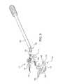
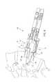
- FIG. 1is a side elevation view of an exemplary embodiment of an instrument constructed in accordance with the present invention, showing the vertebral endplate spreaders mounted to the distal end of a hand operable mechanism for manipulating the spreaders between distracted and retracted positions, and also showing the driver tool for actuating lateral movement of the distal sections of the upper and lower spreaders;
- FIG. 2is a plan view of the instrument of FIG. 1 without the driver, showing the engagement of the spreaders to the hand operable mechanism;
- FIG. 3is an exploded perspective view of the spreaders and driver of FIG. 1 , showing the tongs for engaging upper and lower vertebrae;
- FIG. 4is an exploded perspective view of the upper and lower spreaders of FIG. 3 , showing the separate proximal and distal sections of the each spreader as viewed from above;
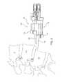
- FIG. 5is a side elevation view of the instrument of FIG. 1 , showing the instrument being introduced from an anterior approach to a listhetic pair of lumbar vertebrae;
- FIG. 6is a side elevation view of the instrument of FIG. 1 , showing the tongs of the instrument being positioned between the listhetic vertebrae;
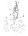
- FIG. 7is a side elevation view of the instrument of FIG. 1 , showing the upper and lower spreaders of the instrument mounted to the respective vertebrae;
- FIG. 8is a side elevation view of the instrument of FIG. 1 , showing the upper and lower spreaders of the instrument distracting the listhetic vertebrae;
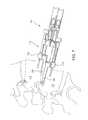
- FIG. 9is a side elevation view of the instrument of FIG. 1 , showing the upper and lower spreaders laterally translated relative to one another for correction of the listhesis.
- FIG. 1a partial view of an exemplary embodiment of an instrument in accordance with the invention is shown in FIG. 1 and is designated generally by reference character 100 .
- FIGS. 2-9Other embodiments of instruments in accordance with the invention, or aspects thereof, are provided in FIGS. 2-9 , as will be described.
- the system of the inventioncan be used to treat spondylolisthesis, scoliosis, and the like.
- Instrument 100includes a distraction mechanism 102 having a proximal end 104 and an opposed distal end 106 .
- Distal end 106includes opposed first and second end members 108 and 110 , respectively.
- a first vertebral endplate spreader 112includes a proximal spreader section 114 .
- Proximal spreader section 114is mounted to first end member 108 of distraction mechanism 102 by mounting pin 122 shown in FIG. 2 .
- First spreader 112also includes a distal spreader section 116 operatively connected to proximal spreader section 114 for lateral movement relative to proximal spreader section 114 .
- a second vertebral endplate spreader 118is mounted to second end member 110 of distraction mechanism 102 by mounting pin 124 , which is identified in FIG. 1 .
- the first and second spreaders 112 and 118are each configured to engage a respective vertebra for correction of vertebral alignment as will be described in greater detail below.
- Distraction mechanism 102is configured and adapted to distract the spreaders 112 and 118 apart from one another and to retract the spreaders 112 and 118 together along a distraction axis A responsive to action imparted on proximal end 104 of distraction mechanism 102 . For example, if a user squeezes the handles of proximal end 104 , spreaders 112 and 118 will be distracted apart from one another, and if a user allows the handles of proximal end 104 to move apart, for example by action of spring 120 , spreaders 112 and 118 will be retracted towards one another.
- spreaders 112 and 118can also move laterally with respect to one another, i.e., in a lateral direction relative to distraction axis A. This lateral movement is made possible by the fact that the spreaders 112 and 118 are each split into proximal and distal sections 114 and 116 to vary the offset as needed by the preexisting listhesis.
- Driver 126is used to turn actuator screws 128 to actuate the displacement of distal spreader sections 116 relative to proximal spreader sections 114 .
- FIG. 4shows parts of spreaders 112 and 118 separated and in the orientation of the procedures described below with reference to FIGS. 5-9 .
- a pair of guides 130is provided for each spreader 112 and 118 , engaged with the proximal and distal spreader sections 114 and 116 to maintain a parallel relationship between the proximal and distal spreader sections 114 and 116 during relative lateral travel thereof.
- Guides 130are rigidly mounted in bores 132 of distal spreader sections 116 and are slideably engaged in bores 134 of proximal spreader sections 114 .
- a linear actuatoris provided in each spreader 112 and 118 in the form of actuator screw 128 , the threads of which engage with corresponding threads in bore 138 of the respective proximal spreader section 114 .
- Each actuator screw 128is rotatably engaged to a respective distal spreader section 116 , with actuator pins 140 mounted in bores 142 and engaged with groove 144 of each respective actuator screw 128 . Rotation of actuator screw 128 adjusts separation of the proximal and distal spreader sections 114 and 116 for relative lateral travel thereof.
- Each distal spreader section 116includes two bone screw bores 146 to provide passages for bone screws to affix each distal spreader section 112 to a respective vertebra.
- Proximal spreader sections 114includes bone screw grooves 148 to provide passage for bone screws and any suitable driver device for affixing distal spreader sections 112 to respective vertebra.
- Each of the distal spreader sections 116includes a pair of tongs 150 for engaging opposed vertebral endplates for distraction of opposed vertebrae, as described in greater detail below.
- FIG. 5schematically shows instrument 100 approaching listhetic vertebrae L4 and L5 from an anterior approach.
- the upper or first spreader 112has its distal spreader section 116 with corresponding tongs 150 in a retracted position.
- the lower or second spreader 118has its distal spreader section 116 and corresponding tongs in an advanced position.
- the relative positions of the upper and lower distal spreader sections 116corresponds to the offset in alignment of the L4 and L5 vertebrae. As indicated in FIG.
- tongs 150 of distal spreader section 116 of first spreader 112are engaged to the listhetic endplate of the L4 vertebra, i.e., the superior or cephalad of the two listhetic vertebrae, and prongs 150 of second spreader 118 are engaged to the adjacent endplate of the L5 vertebra, i.e., the inferior or caudal vertebra.
- FIG. 7shows bone screws affixing the first and second spreaders 112 and 118 to the respective vertebrae prior to distraction.
- spreaders 112 and 118can be affixed with bone screws before or after distraction without departing from the spirit and scope of the invention.
- bone screw affixationmay be omitted for one or both of the spreaders 112 and 118 , for example if the forces engaging the respective prongs 150 to the vertebrae provide sufficient fixation without bone screws. Having both spreaders 112 and 118 secured with screws to the respective vertebrae provides extra stability.
- the proximal end 104 of distraction mechanism 102can be actuated to distract the vertebrae along distraction axis A as indicated by the heavy arrows in FIG. 8 .
- a corpectomy, discectomy, or the likecan be performed as needed.
- driver 126is engaged with actuator screw 128 up upper spreader 112 and turned to spread the upper proximal and distal spreader sections 114 and 116 apart.
- the actuator screw 128 on lower spreader 118can also be turned to move the lower distal spreader section 116 in the opposite direction. This action translates the distal spreader sections 116 relative to the proximal spreader sections 114 laterally with respect to distraction axis A for correction of alignment of the L4 and L5 vertebrae.
- the action of driver 126 and distal spreader sections 116are indicted by the heavy arrows of FIG. 9 .
- Universal joint 152accommodates a range of angles of approach for driver 126 for ease of application.
- Driver 126is depicted with a female hex head, which those skilled in the art will readily appreciate is exemplary, as any suitable driver/head type or linear actuator type can be used without departing from the spirit and scope of the invention.
- an interbody graft or motion sparing devicecan be placed through the enhanced slot between the superior and inferior distractor tongs 150 .
- the surgeoncan check by direct visualization or intra-operative x-rays as to the vertebral alignment and placement of the interbody graft(s) or motion sparing device. If a fusion is performed, instrument 100 is then removed, including the anterior screws. Supplemental anterior plate fixation can then be applied using the holes previously made in the vertebrae to affix the spreaders 112 and 118 .
- the bores 134 in spreader 112 and corresponding bores 134 in spreader 118are spaced apart to allow for a corresponding anterior plating system after the reduction has been performed.
- Instrument 100will thus allow a correction of vertebral alignment related to spondylolisthesis.
- the systems and methods described hereincan also be applied for a retrolisthesis, which is a much less common spinal condition.
- the lateral motion of distal spreader sections 116is reversed to be anterior rather than posterior.
- a smaller version of instrument 100can be used for other applications where smaller size is needed, for example in use on the cervical spine.
- first spreader 112may be referred to as the upper, superior, or cephalad spreader
- second spreader 118may be referred to as the lower, inferior, or caudal spreader.
- each of the spreaders 112 and 118is shown and described as split into proximal and distal sections 116 and 114 for lateral movement, it is also possible to use only one split spreader with another spreader that is not split without departing from the spirit and scope of the invention. If both spreaders are split as described above, additional lateral travel is possible compared to embodiments having only one spreader that is split.
- scoliosisthere are several forms of scoliosis. These include congenital, idiopathic, and degenerative forms. Deformity of the spine involves a lateral or coronal curvature of the spine. In the lumbar spine, especially in degenerative scoliosis, there is often a lateral slippage of one vertebra relative to another.
- the instrumentation described above to reduce an anterior spondylolisthesiscan be used in a lateral approach on the convexity of the curve to reduce the scoliosis and at the same time allow intervertebral distraction.
- An instrument adapted from instrument 100 for treating scoliosis or similar applicationscan be of a smaller diameter and can have one prong on each of the spreaders instead of the two prongs 150 shown and described above.
- the methods and instruments described hereinadvantageously allow for both distraction and relative lateral repositioning of vertebrae. Additional advantages include allowing for disc space distraction which enhances foraminal height. This increased foraminal height reduces the potential for nerve root entrapment during a reduction of the listhesis.
Landscapes
- Health & Medical Sciences (AREA)
- Life Sciences & Earth Sciences (AREA)
- Neurology (AREA)
- Orthopedic Medicine & Surgery (AREA)
- Surgery (AREA)
- Heart & Thoracic Surgery (AREA)
- Engineering & Computer Science (AREA)
- Biomedical Technology (AREA)
- Nuclear Medicine, Radiotherapy & Molecular Imaging (AREA)
- Medical Informatics (AREA)
- Molecular Biology (AREA)
- Animal Behavior & Ethology (AREA)
- General Health & Medical Sciences (AREA)
- Public Health (AREA)
- Veterinary Medicine (AREA)
- Prostheses (AREA)
- Surgical Instruments (AREA)
Abstract
Description
Claims (14)
Priority Applications (6)
| Application Number | Priority Date | Filing Date | Title |
|---|---|---|---|
| US13/287,811US8936599B2 (en) | 2011-11-02 | 2011-11-02 | Translational instrumentation for spondylolisthesis and scoliosis reduction |
| US14/569,218US20150164494A1 (en) | 2011-11-02 | 2014-12-12 | Translational instrumentation for spondylolisthesis and scoliosis reduction |
| US15/362,165US10166048B2 (en) | 2011-11-02 | 2016-11-28 | Translational instrumentation for spondylolisthesis and scoliosis reduction |
| US16/237,385US10898238B2 (en) | 2011-11-02 | 2018-12-31 | Translational instrumentation for spondylolisthesis and scoliosis reduction |
| US17/157,927US20210220024A1 (en) | 2011-11-02 | 2021-01-25 | Translational instrumentation for spondylolisthesis and scoliosis reduction |
| US18/645,652US20240268870A1 (en) | 2011-11-02 | 2024-04-25 | Translational instrumentation for spondylolisthesis and scoliosis reduction |
Applications Claiming Priority (1)
| Application Number | Priority Date | Filing Date | Title |
|---|---|---|---|
| US13/287,811US8936599B2 (en) | 2011-11-02 | 2011-11-02 | Translational instrumentation for spondylolisthesis and scoliosis reduction |
Related Child Applications (1)
| Application Number | Title | Priority Date | Filing Date |
|---|---|---|---|
| US14/569,218DivisionUS20150164494A1 (en) | 2011-11-02 | 2014-12-12 | Translational instrumentation for spondylolisthesis and scoliosis reduction |
Publications (2)
| Publication Number | Publication Date |
|---|---|
| US20130110113A1 US20130110113A1 (en) | 2013-05-02 |
| US8936599B2true US8936599B2 (en) | 2015-01-20 |
Family
ID=48173139
Family Applications (2)
| Application Number | Title | Priority Date | Filing Date |
|---|---|---|---|
| US13/287,811Expired - Fee RelatedUS8936599B2 (en) | 2011-11-02 | 2011-11-02 | Translational instrumentation for spondylolisthesis and scoliosis reduction |
| US14/569,218AbandonedUS20150164494A1 (en) | 2011-11-02 | 2014-12-12 | Translational instrumentation for spondylolisthesis and scoliosis reduction |
Family Applications After (1)
| Application Number | Title | Priority Date | Filing Date |
|---|---|---|---|
| US14/569,218AbandonedUS20150164494A1 (en) | 2011-11-02 | 2014-12-12 | Translational instrumentation for spondylolisthesis and scoliosis reduction |
Country Status (1)
| Country | Link |
|---|---|
| US (2) | US8936599B2 (en) |
Cited By (4)
| Publication number | Priority date | Publication date | Assignee | Title |
|---|---|---|---|---|
| US20140228958A1 (en)* | 2013-02-14 | 2014-08-14 | Marcin Niemiec | Devices and Methods for Correcting Vertebral Misalignment |
| US10123829B1 (en) | 2015-06-15 | 2018-11-13 | Nuvasive, Inc. | Reduction instruments and methods |
| US10537317B2 (en)* | 2015-10-12 | 2020-01-21 | Spine Ortho Center, P.A. | Anterior cervical distractor system and technique |
| US11529173B1 (en)* | 2021-11-12 | 2022-12-20 | Spinal Simplicity, Llc | Reduction system for spondylolisthesis |
Families Citing this family (19)
| Publication number | Priority date | Publication date | Assignee | Title |
|---|---|---|---|---|
| US10709482B2 (en)* | 2012-05-30 | 2020-07-14 | Globus Medical, Inc. | Laminoplasty system |
| EP2722021B1 (en)* | 2012-10-20 | 2017-12-13 | K2M, Inc. | Lateral distractor |
| US9744050B1 (en) | 2013-12-06 | 2017-08-29 | Stryker European Holdings I, Llc | Compression and distraction system for percutaneous posterior spinal fusion |
| US10159579B1 (en) | 2013-12-06 | 2018-12-25 | Stryker European Holdings I, Llc | Tubular instruments for percutaneous posterior spinal fusion systems and methods |
| US9408716B1 (en) | 2013-12-06 | 2016-08-09 | Stryker European Holdings I, Llc | Percutaneous posterior spinal fusion implant construction and method |
| CA2874390C (en) | 2013-12-13 | 2018-03-06 | Stryker European Holdings I, Llc | Tissue retraction and vertebral displacement devices, systems, and methods for posterior spinal fusion |
| US10905566B2 (en)* | 2018-02-05 | 2021-02-02 | Spineology Inc. | Percutaneous posterior implant slide |
| DE102018102695A1 (en)* | 2018-02-07 | 2019-08-08 | Olympus Winter & Ibe Gmbh | Laryngeal Pharyngoscope Retractor System and its Base Frame |
| CN108670327A (en)* | 2018-05-24 | 2018-10-19 | 山西大医院(山西医学科学院) | A kind of lane device applied to operation on vertebra |
| CN109498077B (en)* | 2018-11-14 | 2021-02-26 | 华北水利水电大学 | Lumbar spondylolisthesis repositor |
| GB201818850D0 (en) | 2018-11-19 | 2019-01-02 | Axis Spine Tech Ltd | Intervertebral devices |
| GB201902002D0 (en) | 2019-02-13 | 2019-04-03 | Axis Spine Tech Ltd | Intervertebral devices |
| GB201818847D0 (en) | 2018-11-19 | 2019-01-02 | Axis Spine Tech Ltd | Intervertebral devices |
| GB201818849D0 (en) | 2018-11-19 | 2019-01-02 | Axis Spine Tech Ltd | Intervertebral devices |
| GB202000890D0 (en) | 2020-01-21 | 2020-03-04 | Axis Spine Tech Ltd | Intervertebral devices |
| GB201910668D0 (en) | 2019-07-25 | 2019-09-11 | Axis Spine Tech Ltd | Assemblies for and methods of determing height and angle of an intervertebral device |
| GB201910640D0 (en) | 2019-07-25 | 2019-09-11 | Axis Spine Tech Ltd | Insertions instruments |
| CN111436987A (en)* | 2020-05-12 | 2020-07-24 | 中国医科大学附属第一医院 | Cervical vertebra dislocation struts pressurization restorer |
| CN118750140B (en)* | 2024-06-04 | 2025-02-21 | 苏州市康力骨科器械有限公司 | Orthopedic operation baffle |
Citations (12)
| Publication number | Priority date | Publication date | Assignee | Title |
|---|---|---|---|---|
| US4957495A (en)* | 1987-04-01 | 1990-09-18 | Patrick Kluger | Device for setting the spinal column |
| US5601556A (en)* | 1994-03-18 | 1997-02-11 | Pisharodi; Madhavan | Apparatus for spondylolisthesis reduction |
| US6168601B1 (en)* | 1999-05-14 | 2001-01-02 | Giuseppe Martini | Lock reduction device and method |
| US6558392B1 (en)* | 1999-05-14 | 2003-05-06 | Giuseppe Martini | Lock reduction device and method |
| US20050245928A1 (en)* | 2004-05-03 | 2005-11-03 | Innovative Spinal Technologies | System and method for displacement of bony structures |
| US20070191856A1 (en)* | 2006-01-31 | 2007-08-16 | Sdgi Holdings, Inc. | Adjustable height spinal distractor |
| US7744649B2 (en) | 2007-06-25 | 2010-06-29 | Moore Mark R | Spondylolisthesis correction apparatus and method |
| US20100249792A1 (en)* | 2002-05-21 | 2010-09-30 | Bonvallet Todd C | Instruments and techniques for separating bony structures |
| US7811288B2 (en) | 2004-12-02 | 2010-10-12 | Zimmer Spine, Inc. | Instruments and methods for adjusting separation distance of vertebral bodies with a minimally invasive spinal stabilization procedure |
| US20100274252A1 (en)* | 2009-04-23 | 2010-10-28 | The Johns Hopkins University | Vertebral body reduction instrument and methods related thereto |
| US7988700B2 (en) | 2002-06-24 | 2011-08-02 | Zimmer Spine, Inc. | Surgical instrument for moving vertebrae |
| US8007517B2 (en) | 2004-10-25 | 2011-08-30 | Lanx, Inc. | Interspinous distraction devices and associated methods of insertion |
- 2011
- 2011-11-02USUS13/287,811patent/US8936599B2/ennot_activeExpired - Fee Related
- 2014
- 2014-12-12USUS14/569,218patent/US20150164494A1/ennot_activeAbandoned
Patent Citations (12)
| Publication number | Priority date | Publication date | Assignee | Title |
|---|---|---|---|---|
| US4957495A (en)* | 1987-04-01 | 1990-09-18 | Patrick Kluger | Device for setting the spinal column |
| US5601556A (en)* | 1994-03-18 | 1997-02-11 | Pisharodi; Madhavan | Apparatus for spondylolisthesis reduction |
| US6168601B1 (en)* | 1999-05-14 | 2001-01-02 | Giuseppe Martini | Lock reduction device and method |
| US6558392B1 (en)* | 1999-05-14 | 2003-05-06 | Giuseppe Martini | Lock reduction device and method |
| US20100249792A1 (en)* | 2002-05-21 | 2010-09-30 | Bonvallet Todd C | Instruments and techniques for separating bony structures |
| US7988700B2 (en) | 2002-06-24 | 2011-08-02 | Zimmer Spine, Inc. | Surgical instrument for moving vertebrae |
| US20050245928A1 (en)* | 2004-05-03 | 2005-11-03 | Innovative Spinal Technologies | System and method for displacement of bony structures |
| US8007517B2 (en) | 2004-10-25 | 2011-08-30 | Lanx, Inc. | Interspinous distraction devices and associated methods of insertion |
| US7811288B2 (en) | 2004-12-02 | 2010-10-12 | Zimmer Spine, Inc. | Instruments and methods for adjusting separation distance of vertebral bodies with a minimally invasive spinal stabilization procedure |
| US20070191856A1 (en)* | 2006-01-31 | 2007-08-16 | Sdgi Holdings, Inc. | Adjustable height spinal distractor |
| US7744649B2 (en) | 2007-06-25 | 2010-06-29 | Moore Mark R | Spondylolisthesis correction apparatus and method |
| US20100274252A1 (en)* | 2009-04-23 | 2010-10-28 | The Johns Hopkins University | Vertebral body reduction instrument and methods related thereto |
Cited By (8)
| Publication number | Priority date | Publication date | Assignee | Title |
|---|---|---|---|---|
| US20140228958A1 (en)* | 2013-02-14 | 2014-08-14 | Marcin Niemiec | Devices and Methods for Correcting Vertebral Misalignment |
| US9585765B2 (en)* | 2013-02-14 | 2017-03-07 | Globus Medical, Inc | Devices and methods for correcting vertebral misalignment |
| US10123829B1 (en) | 2015-06-15 | 2018-11-13 | Nuvasive, Inc. | Reduction instruments and methods |
| US10743921B2 (en) | 2015-06-15 | 2020-08-18 | Nuvasive, Inc. | Reduction instruments and methods |
| US11690657B2 (en) | 2015-06-15 | 2023-07-04 | Nuvasive, Inc. | Reduction instruments and methods |
| US12262929B2 (en) | 2015-06-15 | 2025-04-01 | Nuvasive, Inc. | Reduction instruments and methods |
| US10537317B2 (en)* | 2015-10-12 | 2020-01-21 | Spine Ortho Center, P.A. | Anterior cervical distractor system and technique |
| US11529173B1 (en)* | 2021-11-12 | 2022-12-20 | Spinal Simplicity, Llc | Reduction system for spondylolisthesis |
Also Published As
| Publication number | Publication date |
|---|---|
| US20130110113A1 (en) | 2013-05-02 |
| US20150164494A1 (en) | 2015-06-18 |
Similar Documents
| Publication | Publication Date | Title |
|---|---|---|
| US8936599B2 (en) | Translational instrumentation for spondylolisthesis and scoliosis reduction | |
| US20240268870A1 (en) | Translational instrumentation for spondylolisthesis and scoliosis reduction | |
| US11426292B2 (en) | Spinal implant system and method | |
| US9480502B2 (en) | Expansion interspinous fixation device and method | |
| US8496661B2 (en) | System and method for micro-invasive transfacet lumbar interbody fusion | |
| US10258388B2 (en) | Device and method for treatment of spondylotic disease | |
| EP2667807B1 (en) | Instruments for adjusting relative positioning of bones or bony tissues | |
| US20180064555A1 (en) | Expandable interbody implant | |
| US9211195B2 (en) | Expandable interbody implant and method | |
| AU2016288596A1 (en) | Expandable implant | |
| AU2006304821A1 (en) | Method and instruments to treat spondylolisthesis by an anterior minimally invasive approach of the spine | |
| EP2722022B1 (en) | Insertion device for use with an expandable cage | |
| MX2012005333A (en) | Facet distraction device, facet joint implant, and associated methods. | |
| WO2007123979A2 (en) | Cervical plate system | |
| WO2012009038A1 (en) | Devices, systems, and methods for inter-transverse process dynamic stabilization | |
| US11517356B2 (en) | Spinal plate bender | |
| US12433580B1 (en) | Adjustable angle cervical spine distractor | |
| LENKE | TLIF in Pediatric Deformity | |
| Elston et al. | Lumbosacral Instrumentation |
Legal Events
| Date | Code | Title | Description |
|---|---|---|---|
| AS | Assignment | Owner name:TENZIN LLC, MASSACHUSETTS Free format text:ASSIGNMENT OF ASSIGNORS INTEREST;ASSIGNOR:GLAZER, PAUL;REEL/FRAME:028870/0748 Effective date:20120807 | |
| STCF | Information on status: patent grant | Free format text:PATENTED CASE | |
| FEPP | Fee payment procedure | Free format text:MAINTENANCE FEE REMINDER MAILED (ORIGINAL EVENT CODE: REM.); ENTITY STATUS OF PATENT OWNER: SMALL ENTITY | |
| FEPP | Fee payment procedure | Free format text:SURCHARGE FOR LATE PAYMENT, SMALL ENTITY (ORIGINAL EVENT CODE: M2554); ENTITY STATUS OF PATENT OWNER: SMALL ENTITY | |
| MAFP | Maintenance fee payment | Free format text:PAYMENT OF MAINTENANCE FEE, 4TH YR, SMALL ENTITY (ORIGINAL EVENT CODE: M2551); ENTITY STATUS OF PATENT OWNER: SMALL ENTITY Year of fee payment:4 | |
| AS | Assignment | Owner name:ALPHATEC SPINE, INC., CALIFORNIA Free format text:ASSIGNMENT OF ASSIGNORS INTEREST;ASSIGNOR:TENZIN LLC;REEL/FRAME:058972/0301 Effective date:20211209 | |
| FEPP | Fee payment procedure | Free format text:MAINTENANCE FEE REMINDER MAILED (ORIGINAL EVENT CODE: REM.); ENTITY STATUS OF PATENT OWNER: SMALL ENTITY | |
| AS | Assignment | Owner name:MIDCAP FUNDING IV TRUST, MARYLAND Free format text:SECURITY INTEREST;ASSIGNORS:ALPHATEC SPINE, INC.;SAFEOP SURGICAL, INC.;REEL/FRAME:062310/0001 Effective date:20230106 | |
| AS | Assignment | Owner name:WILMINGTON TRUST, NATIONAL ASSOCIATION, DELAWARE Free format text:SECURITY INTEREST;ASSIGNORS:ALPHATEC SPINE, INC.;SAFEOP SURGICAL, INC.;REEL/FRAME:062681/0020 Effective date:20230106 | |
| LAPS | Lapse for failure to pay maintenance fees | Free format text:PATENT EXPIRED FOR FAILURE TO PAY MAINTENANCE FEES (ORIGINAL EVENT CODE: EXP.); ENTITY STATUS OF PATENT OWNER: SMALL ENTITY | |
| STCH | Information on status: patent discontinuation | Free format text:PATENT EXPIRED DUE TO NONPAYMENT OF MAINTENANCE FEES UNDER 37 CFR 1.362 | |
| FP | Lapsed due to failure to pay maintenance fee | Effective date:20230120 |