US8936592B2 - Laser tissue ablation system - Google Patents
Laser tissue ablation systemDownload PDFInfo
- Publication number
- US8936592B2 US8936592B2US13/152,825US201113152825AUS8936592B2US 8936592 B2US8936592 B2US 8936592B2US 201113152825 AUS201113152825 AUS 201113152825AUS 8936592 B2US8936592 B2US 8936592B2
- Authority
- US
- United States
- Prior art keywords
- balloon
- laser
- fiber
- shaft
- distal end
- Prior art date
- Legal status (The legal status is an assumption and is not a legal conclusion. Google has not performed a legal analysis and makes no representation as to the accuracy of the status listed.)
- Expired - Fee Related, expires
Links
Images


Classifications
- A—HUMAN NECESSITIES
- A61—MEDICAL OR VETERINARY SCIENCE; HYGIENE
- A61B—DIAGNOSIS; SURGERY; IDENTIFICATION
- A61B18/00—Surgical instruments, devices or methods for transferring non-mechanical forms of energy to or from the body
- A61B18/18—Surgical instruments, devices or methods for transferring non-mechanical forms of energy to or from the body by applying electromagnetic radiation, e.g. microwaves
- A61B18/20—Surgical instruments, devices or methods for transferring non-mechanical forms of energy to or from the body by applying electromagnetic radiation, e.g. microwaves using laser
- A61B18/22—Surgical instruments, devices or methods for transferring non-mechanical forms of energy to or from the body by applying electromagnetic radiation, e.g. microwaves using laser the beam being directed along or through a flexible conduit, e.g. an optical fibre; Couplings or hand-pieces therefor
- A61B18/24—Surgical instruments, devices or methods for transferring non-mechanical forms of energy to or from the body by applying electromagnetic radiation, e.g. microwaves using laser the beam being directed along or through a flexible conduit, e.g. an optical fibre; Couplings or hand-pieces therefor with a catheter
- A—HUMAN NECESSITIES
- A61—MEDICAL OR VETERINARY SCIENCE; HYGIENE
- A61B—DIAGNOSIS; SURGERY; IDENTIFICATION
- A61B18/00—Surgical instruments, devices or methods for transferring non-mechanical forms of energy to or from the body
- A61B18/18—Surgical instruments, devices or methods for transferring non-mechanical forms of energy to or from the body by applying electromagnetic radiation, e.g. microwaves
- A61B18/20—Surgical instruments, devices or methods for transferring non-mechanical forms of energy to or from the body by applying electromagnetic radiation, e.g. microwaves using laser
- A61B18/22—Surgical instruments, devices or methods for transferring non-mechanical forms of energy to or from the body by applying electromagnetic radiation, e.g. microwaves using laser the beam being directed along or through a flexible conduit, e.g. an optical fibre; Couplings or hand-pieces therefor
- A—HUMAN NECESSITIES
- A61—MEDICAL OR VETERINARY SCIENCE; HYGIENE
- A61B—DIAGNOSIS; SURGERY; IDENTIFICATION
- A61B17/00—Surgical instruments, devices or methods
- A61B17/42—Gynaecological or obstetrical instruments or methods
- A61B2017/4216—Operations on uterus, e.g. endometrium
- A—HUMAN NECESSITIES
- A61—MEDICAL OR VETERINARY SCIENCE; HYGIENE
- A61B—DIAGNOSIS; SURGERY; IDENTIFICATION
- A61B18/00—Surgical instruments, devices or methods for transferring non-mechanical forms of energy to or from the body
- A61B2018/00053—Mechanical features of the instrument of device
- A61B2018/00184—Moving parts
- A61B2018/00196—Moving parts reciprocating lengthwise
- A—HUMAN NECESSITIES
- A61—MEDICAL OR VETERINARY SCIENCE; HYGIENE
- A61B—DIAGNOSIS; SURGERY; IDENTIFICATION
- A61B18/00—Surgical instruments, devices or methods for transferring non-mechanical forms of energy to or from the body
- A61B2018/00053—Mechanical features of the instrument of device
- A61B2018/00184—Moving parts
- A61B2018/00202—Moving parts rotating
- A—HUMAN NECESSITIES
- A61—MEDICAL OR VETERINARY SCIENCE; HYGIENE
- A61B—DIAGNOSIS; SURGERY; IDENTIFICATION
- A61B18/00—Surgical instruments, devices or methods for transferring non-mechanical forms of energy to or from the body
- A61B2018/00053—Mechanical features of the instrument of device
- A61B2018/00214—Expandable means emitting energy, e.g. by elements carried thereon
- A61B2018/0022—Balloons
- A61B2018/00226—Balloons extending from a surface, i.e. Blisters
- A—HUMAN NECESSITIES
- A61—MEDICAL OR VETERINARY SCIENCE; HYGIENE
- A61B—DIAGNOSIS; SURGERY; IDENTIFICATION
- A61B18/00—Surgical instruments, devices or methods for transferring non-mechanical forms of energy to or from the body
- A61B2018/00315—Surgical instruments, devices or methods for transferring non-mechanical forms of energy to or from the body for treatment of particular body parts
- A61B2018/00559—Female reproductive organs
- A—HUMAN NECESSITIES
- A61—MEDICAL OR VETERINARY SCIENCE; HYGIENE
- A61B—DIAGNOSIS; SURGERY; IDENTIFICATION
- A61B18/00—Surgical instruments, devices or methods for transferring non-mechanical forms of energy to or from the body
- A61B2018/00571—Surgical instruments, devices or methods for transferring non-mechanical forms of energy to or from the body for achieving a particular surgical effect
- A61B2018/00577—Ablation
- A—HUMAN NECESSITIES
- A61—MEDICAL OR VETERINARY SCIENCE; HYGIENE
- A61B—DIAGNOSIS; SURGERY; IDENTIFICATION
- A61B18/00—Surgical instruments, devices or methods for transferring non-mechanical forms of energy to or from the body
- A61B2018/00982—Surgical instruments, devices or methods for transferring non-mechanical forms of energy to or from the body combined with or comprising means for visual or photographic inspections inside the body, e.g. endoscopes
- A61B2018/0196—
- A—HUMAN NECESSITIES
- A61—MEDICAL OR VETERINARY SCIENCE; HYGIENE
- A61B—DIAGNOSIS; SURGERY; IDENTIFICATION
- A61B18/00—Surgical instruments, devices or methods for transferring non-mechanical forms of energy to or from the body
- A61B18/18—Surgical instruments, devices or methods for transferring non-mechanical forms of energy to or from the body by applying electromagnetic radiation, e.g. microwaves
- A61B18/1815—Surgical instruments, devices or methods for transferring non-mechanical forms of energy to or from the body by applying electromagnetic radiation, e.g. microwaves using microwaves
- A61B2018/1861—Surgical instruments, devices or methods for transferring non-mechanical forms of energy to or from the body by applying electromagnetic radiation, e.g. microwaves using microwaves with an instrument inserted into a body lumen or cavity, e.g. a catheter
- A—HUMAN NECESSITIES
- A61—MEDICAL OR VETERINARY SCIENCE; HYGIENE
- A61B—DIAGNOSIS; SURGERY; IDENTIFICATION
- A61B18/00—Surgical instruments, devices or methods for transferring non-mechanical forms of energy to or from the body
- A61B18/18—Surgical instruments, devices or methods for transferring non-mechanical forms of energy to or from the body by applying electromagnetic radiation, e.g. microwaves
- A61B18/20—Surgical instruments, devices or methods for transferring non-mechanical forms of energy to or from the body by applying electromagnetic radiation, e.g. microwaves using laser
- A61B18/22—Surgical instruments, devices or methods for transferring non-mechanical forms of energy to or from the body by applying electromagnetic radiation, e.g. microwaves using laser the beam being directed along or through a flexible conduit, e.g. an optical fibre; Couplings or hand-pieces therefor
- A61B2018/2244—Features of optical fibre cables, e.g. claddings
- A—HUMAN NECESSITIES
- A61—MEDICAL OR VETERINARY SCIENCE; HYGIENE
- A61B—DIAGNOSIS; SURGERY; IDENTIFICATION
- A61B18/00—Surgical instruments, devices or methods for transferring non-mechanical forms of energy to or from the body
- A61B18/18—Surgical instruments, devices or methods for transferring non-mechanical forms of energy to or from the body by applying electromagnetic radiation, e.g. microwaves
- A61B18/20—Surgical instruments, devices or methods for transferring non-mechanical forms of energy to or from the body by applying electromagnetic radiation, e.g. microwaves using laser
- A61B18/22—Surgical instruments, devices or methods for transferring non-mechanical forms of energy to or from the body by applying electromagnetic radiation, e.g. microwaves using laser the beam being directed along or through a flexible conduit, e.g. an optical fibre; Couplings or hand-pieces therefor
- A61B2018/2255—Optical elements at the distal end of probe tips
- A61B2018/2261—Optical elements at the distal end of probe tips with scattering, diffusion or dispersion of light
- A61B2019/5217—
- A—HUMAN NECESSITIES
- A61—MEDICAL OR VETERINARY SCIENCE; HYGIENE
- A61B—DIAGNOSIS; SURGERY; IDENTIFICATION
- A61B90/00—Instruments, implements or accessories specially adapted for surgery or diagnosis and not covered by any of the groups A61B1/00 - A61B50/00, e.g. for luxation treatment or for protecting wound edges
- A61B90/36—Image-producing devices or illumination devices not otherwise provided for
- A61B90/361—Image-producing devices, e.g. surgical cameras
- A61B2090/3614—Image-producing devices, e.g. surgical cameras using optical fibre
Definitions
- Pelvic conditionsinclude diseases of the uterus, such as uterine fibroids and menorrhagia.
- Uterine fibroidsare non-cancerous tumors of the uterus that typically appear on the endometrium layer (i.e., uterine wall) of the uterus.
- Menorrhagiais a medical condition involving excessive and difficult to control bleeding of the endometrial layer of the uterus. These conditions have been treated through hysterectomy. However, alternative, less radical approaches are also being used.
- endometrial ablationwhich induces necrosis of the endometrial layer and a portion of the myometrial layer.
- treatmentscan include freezing and heating the endometrial layer, or cauterizing the endometrial layer using a laser.
- the laser ablation systemcomprises a shaft, a balloon, a laser fiber and a viewing fiber.
- the shafthas a proximal end and a distal end.
- the balloonis attached to the distal end of the shaft, a portion of which is within the balloon.
- the laser fiberhas a distal end comprising a light dispenser that is configured to deliver laser light through the balloon.
- the viewing fiberis configured to image an interior balloon.
- the laser ablation systemcomprises a shaft, a balloon and a laser fiber.
- the shafthas a proximal end and a distal end.
- the balloonis attached to the distal end of the shaft, which is within the balloon.
- the balloonincludes an inflated state, in which the balloon is shaped to conform to a cavity of a patient.
- the laser fiberhas a distal end comprising light dispenser that is configured to deliver laser light through the balloon.
- a laser ablation systemcomprising a shaft, a balloon and a laser fiber.
- the shafthas a proximal end and a distal end.
- the balloonis attached to the distal end of the shaft, which is within the balloon.
- the balloonincludes an inflated state, in which the balloon is shaped to conform to a uterine cavity of a patient.
- the laser fiberhas a distal end comprising a light dispenser that is configured to deliver laser light through the balloon. Also in the method, the distal end of the shaft is fed into the uterus of a patient with the balloon in a deflated state.
- the balloonis inflated with a gas or fluid to the inflated state, in which the balloon substantially conforms to the uterine cavity of the patient and engages the uterine walls.
- Laser lightis then transmitted through the laser fiber and, the light dispenser and the balloon.
- the tissue of the uterine wallsis ablated responsive to the transmission of the laser light.
- FIG. 1is a simplified diagram of a laser tissue ablation system formed in accordance with embodiments of the invention.
- FIG. 2is a cross-sectional view illustrating the attachment of a distal end of a shaft to a balloon, in accordance with an exemplary embodiment.
- FIGS. 3 and 4are simplified diagrams of inflated balloons in accordance with embodiments of the invention.
- FIG. 5is a cross-sectional view depicting pelvic anatomy of a female patient and a distal end of the applicator formed in accordance with embodiments of the invention.
- FIG. 6is an isometric view of a balloon in accordance with embodiments of the invention.
- FIGS. 7 and 8are side cross-sectional views of a distal end of an applicator illustrating fluid or gas flow in accordance with embodiments of the invention.
- FIGS. 9 and 10are side views of light dispensers in accordance with embodiments of the invention.
- FIGS. 11 and 12are side views of the distal end of the applicator illustrating laser fiber positioning components in accordance with embodiments of the invention.
- FIG. 13is a simplified diagram of the applicator including a handheld unit in accordance with embodiments of the invention.
- FIGS. 14-16respectively show isometric assembled, isometric exploded and magnified isometric views of the applicator with a handheld unit formed in accordance with exemplary embodiments of the invention.
- Embodiments of the present inventionare directed to a laser tissue ablation system designed to perform tissue ablation and/or other laser treatments on a patient. While particular embodiments of the invention will be described as useful in treating menorrhagia through endometrial ablation of the uterine wall of a patient, those skilled in the art understand that the system of a present invention may be adapted to perform ablation treatments of other tissue of a patient, such as that of the anal cavity, the bladder, the vagina, the esophagus, the trachea, the urethra, the ureter, the prostate gland, the kidney, intestinal growths or abnormal tissues of the intestine (e.g., hemorrhoids, polyps, etc.) and cancerous tissues.
- tissue of a patientsuch as that of the anal cavity, the bladder, the vagina, the esophagus, the trachea, the urethra, the ureter, the prostate gland, the kidney, intestinal growths or abnormal tissues of the intestin
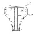
- FIG. 1is a simplified diagram of a laser tissue ablation system 100 formed in accordance with embodiments of the invention.
- One embodiment of the system 100includes an applicator 102 that is formed in accordance with the embodiments described below.
- the applicator 102comprises a shaft 104 having a proximal end 106 and a distal end 108 .
- One embodiment of the shaft 104is formed of a rigid and substantially transparent material, such as, for example, acrylic, PET, silicone, polyurethane, polycarbonate, glass or other suitable material.
- the applicator 102includes a balloon 110 that is attached to the shaft 104 proximate the distal end 108 .
- the balloon 110comprises a proximal end 112 and a distal end 114 .
- the proximal end 112is attached to the shaft 104 by a sleeve 116 that is formed, for example out of Teflon®, which seals an opening of the balloon 110 to the shaft 104 .
- the distal end 108 of the shaft 104is attached to the distal end 114 of the balloon 110 .
- the shaft 104has a longitudinal axis 117 .
- the distal end 108 of the shaft 104is secured to the distal end 114 of the balloon 110 along longitudinal axis 117 .
- the longitudinal axis 117is aligned with a central axis 118 of the balloon 110 .
- the balloonis symmetric about the longitudinal or central axis 117 when inflated.
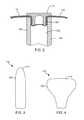
- FIG. 2is a cross-sectional view illustrating an exemplary means of attaching the shaft 104 to the balloon 110 using a cap 119 .
- the cap 119comprises a cylindrical portion 120 that is received within a bore 122 of the shaft 104 .
- the distal end 114 of the balloon 110is captured between the surfaces of the cylindrical portion 120 of the cap 119 and the shaft 104 .
- frictional resistanceprevents the cap 119 from becoming dislodged from the bore 122 of the shaft 104 .
- a biocompatible adhesivemay also be used to secure the cap 119 to the distal end 108 of the shaft 104 .
- Other techniquesmay also be used to secure the balloon 110 to the distal end 108 of the shaft 104 .
- the balloon 110has deflated and inflated states.
- the deflated state 124 of the balloon 110is preferably sufficiently compact to allow the distal end 108 of the shaft 104 and the attached balloon 110 to be inserted into the desired cavity of the patient, such as the uterus or vagina, to locate the balloon 110 proximate the tissue targeted for treatment.
- the deflated state of the balloon 110is approximately 4-6 mm or less in diameter measured radially from the central axis 118 of the balloon 110 .
- the balloon 110When in the inflated state, the balloon 110 substantially conforms to the cavity in which it is placed.
- the balloon 110is be formed of a suitable biocompatible material.
- the balloon 110is formed of a distensible material, such as silicone, PET, polyurethane, rubber or other suitable material.
- the distensible materialcan stretch responsive to inflating the balloon 110 from a deflated state 124 (illustrated in phantom in FIG. 1 ) to an inflated state 126 (solid line), as shown in FIG. 1 , due to an increase in the pressure of the interior 128 of the balloon 110 .
- the distensible materialallows the balloon 110 to further conform to the cavity of the patient in which it is placed in response to pressure exerted on the balloon 110 from the walls of the cavity.
- the balloon 110is formed of minimally distensible material, such as polyurethane, or other suitable material.
- the balloon 110includes an Inhibizone coating, such as that described in U.S. Pat. No. 5,756,145, which is incorporated herein by reference in its entirety.
- FIGS. 3 and 4are simplified diagrams of the balloon 110 in the inflated state 126 , in accordance with embodiments of the invention.
- the inflated state 126 of the balloon 110has a cylindrical shape with a rounded distal end 114 , as illustrated in FIGS. 1 and 3 .
- the inflated state 126 of the balloon 110has a predefined non-cylindrical or spherical shape when viewed in a plane aligned with the central axis of the balloon 117 . Rather, the inflated state 126 of the balloon has a shape that conforms to the interior cavity of the patient where the tissue targeted for ablation is located.
- One exemplary embodimentis illustrated in the simplified side view of FIG. 4 , in which the inflated state 126 of the balloon 110 is shaped to conform to the uterus of a patient.
- the balloon 110can take on other cavity-conforming shapes, such as the vagina, the anal cavity, esophagus, trachea, bladder and any other cavity within the body.
- the predefined inflated shape 126 of the balloon 110will drive the tissue of the cavity into conformity with the balloon 110 .
- the inflated state 126 of the balloonwill generally conform to the cavity of the patient.
- the balloon 110may only minimally deflect the walls of the cavity when the balloon is inflated. Further, the balloon 110 will also deform in response to engagement with the walls of the cavity.
- the pre-defined shape of the inflated state 126 of the balloonprevents the balloon from applying significant pressures to the walls of the cavity of the patient.
- the balloon 110applies less than 10 psi to the walls of the cavity of the patient in which it is inflated.
- the balloon 110 having a pre-defined inflated shapecan significantly reduce the pressure on the walls of the cavity of the patient in which the balloon 110 is inflated. This can reduce patient intraoperative and post operative pain.
- FIG. 5is a cross-sectional view of a female patient depicting the vagina 132 , the cervix 134 and the uterus 136 .
- the distal end 108 of the shaft 104 and a balloon 110are inserted through the cervix 134 and into the uterus 136 when the balloon 110 is in the deflated state 124 .
- the balloon 110is then expanded to the inflated state 126 (shown), in which the balloon 110 substantially conforms to the shape of the uterine wall 138 .
- the balloon 110preferably engages the uterine wall 138 while applying minimal pressure. In one embodiment, the balloon 110 applies less than 10 psi to the uterine wall 138 when in the inflated state 126 .
- the balloon 110includes markings 139 , as shown in FIG. 6 .
- the markings 139can be viewed from within the interior 128 to determine whether the balloon 110 is properly inflated and/or positioned within the cavity of the patient.
- the markings 139comprise one or more visible lines extending longitudinally (i.e., lines 139 A), and/or circumferentially (i.e., lines 139 B) around the balloon 110 .
- the markings 139comprise a grid pattern.
- the balloon 110seals the distal end 108 of the shaft 104 .
- a seal 142such as an o-ring, or other suitable seal, seals the proximal end 106 of the shaft 104 .
- the balloon 110is inflated using a simple saline solution.
- the balloon 110may be inflated with fluid or gas.
- the shaft 104includes a port 140 , as shown in FIG. 1 , through which the fluid or gas may be received.
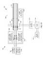
- the system 100comprises a pump 144 that drives a fluid or gas from a supply 146 through the port 140 and into the interior 128 of the balloon 110 to drive the balloon 110 to its inflated state 126 .
- the pump 144can take on many different forms.
- the supply 146is in the form of a pressurized gas, in which case, the pump 144 may represent a valve that controls the flow of the gas from the supply 146 .
- the pump 144drives a fluid from the supply 146 through the port 140 and into the interior 128 of the balloon 110 to inflate the balloon 110 .
- Embodiments of the pump 144include a syringe, a diaphragm pump, gear pump, or other suitable pump.
- gas or fluidenters the shaft 104 through the port 140 , shown in FIG. 1 .
- the shaft 104includes a fluid path 149 that fluidically couples the port 140 to openings 148 in the shaft 104 to the interior 128 of the balloon 110 , as shown in FIG. 7 .
- the gas or fluid entering the port 140flows through the fluid path 149 , through the openings 148 and into the interior 128 of the balloon 110 as shown in FIGS. 1 and 7 .
- the fluid or gas within the interior cavity 128 of the balloon 110may be discharged back through the openings 148 of the shaft 104 and out the port 140 .
- the fluid or gas within the interior cavity 128 of the balloon 110may be discharged through one or more openings 150 to a fluid path 152 that is connected to a dedicated drain port 154 ( FIG. 1 ).
- the balloon 110comprises an interior balloon 110 A and an exterior balloon 110 B, as shown in the simplified side-cross sectional view of FIG. 8 .
- either the interior balloon 110 A or the exterior balloon 110 Bis formed of a non-distensible material, while the other balloon 110 A or 110 B is formed of a distensible material.
- the interior balloon 110 Ais formed of a substantially non-distensible or minimally distensible material and has a predefined shaped in accordance with embodiments described above.
- a biocompatible lubricantis located between the interior balloon 110 A and the exterior balloon 110 B.
- the fluid or gas driven through the port 140is fed between the interior balloon 110 A and the exterior balloon 110 B, as represented by the arrows in FIG. 8 .
- the fluidis discharged through the fluid path 152 and out the drain port 154 .
- the flow of fluid between the balloons 110 A and 110 Bcan be used to control the temperature of the tissue that is in contact with the balloon 110 B.
- One embodiment of the system 100includes a conventional laser source 160 that can be attached to a waveguide 162 , such as an optical fiber (hereinafter “laser fiber”), that can be received within the shaft 104 .
- the laser source 160can be a conventional laser generating system.
- the laser source 160is configured to generate laser light or a laser 164 having a desired wavelength for performing surgical procedures, such as tissue ablation.
- the laser source 160is configured to produce an Nd:YAG laser operating at approximately 532 nanometers or 1064 nanometer wavelengths.
- the laser source 160may be a solid state laser based on a potassium-titanyl-phosphate (KTP) crystal, a lithium triborate (LBO) laser, a beta barium borate (BBO), a holmium laser and a thulium laser, or other type of laser source used to perform tissue ablation or other laser treatment.
- KTPpotassium-titanyl-phosphate
- LBOlithium triborate
- BBObeta barium borate
- Exemplary laser sources 160are described in U.S. Pat. No. 6,986,764 (Davenport), which is incorporated herein by reference in its entirety.
- the laser 164 generated by the laser source 160travels through the laser fiber 162 and is discharged through a light dispenser 166 at a distal end 168 .
- the dispensed laser light 164is transmitted through the shaft 104 and the balloon 110 and onto the targeted tissue of the patient, such as the uterine wall 138 shown in FIG. 5 .
- the light dispenser 166is configured to discharge the laser light 164 in a desired manner, such as along the axial and/or radial directions of the laser fiber 162 , to one side of the laser fiber 162 , in a diffuse pattern around the dispenser 166 , and/or other desired manner.
- Exemplary light dispensers 166such as side-fire optical caps, are disclosed in U.S. Pat. No. 5,428,699 (Pon), U.S. Pat. No. 5,269,777 (Doiron et al.), U.S. Pat. No. 5,530,780 (Ohsawa), and U.S. Pat. No. 5,807,390 (Fuller et al.).
- the light dispenser 166comprises an etched section 170 of the laser fiber 162 , as shown in FIG. 9 , to dispense the laser light 164 in a diffuse pattern.
- portions of the etched section 170are tapered to direct the diffused laser light in a desired manner, such as axially.
- the etchingcan be made using an appropriate laser, such as a CO 2 laser, to roughen the exterior surface of the laser fiber 162 .
- a cap 172encloses the dispenser 166 , as shown in FIG. 9 .
- the etching pattern of the section 170is customized to include portions that transmit more light energy than other portions to customize the laser energy dispersion pattern output from the dispenser 166 . That is, the etched section 170 may comprise different patterns in different portions of the section 170 to provide different levels of laser light transmission through the different portions of the section 170 . This allows the targeted tissue to receive similar intensity levels of the dispensed laser light 164 even though the targeted tissue is not located a uniform distance from the dispenser 166 .
- light transmission through the balloon 110is non-uniform.
- light transmission through the balloonvaries along the central axis 118 of the balloon 110 . That is, portions of the balloon 110 at different locations along the axis 118 (e.g., portions in a plane that is perpendicular to the axis 118 ) have a degree of laser transparency that is different from other portions of the balloon along the axis 118 . This allows for the control of the transmission of the laser light 164 through the balloon 110 and, therefore, the amount of laser energy that is delivered to the targeted tissue.
- the material forming the balloonprovides a predefined pattern of laser transparency variation along the axis 118 , such as, for example, by varying a thickness of the balloon 110 .
- printing or a coating of material on of the balloon 110defines the desired pattern of laser transparency though the balloon 110 .
- the printing or coatingdefines the pattern of laser transparency by applying the printing or coating to select portions of the balloon 110 , applying the printing or coating in a varying pattern on the balloon 110 , and/or applying the printing or coating in a varying thickness on the balloon 110 .
- Embodiments of the coatingmay comprise titanium dioxide (TiO 2 ), Tampapur Ink, and/or parylene.
- the coated or printed materialis reflective.
- FIG. 10illustrates a simplified diagram of a light dispenser 166 in accordance with another embodiment of the invention.
- the light dispenser 166comprises a plurality of glass beads 174 within the balloon 110 .
- the laser lightis discharged through the distal end 168 of the laser fiber 162 and interacts with the glass beads 174 to disperse the laser light 164 around the surface of the balloon 110 .
- the distal end 108 of the shaft 104is configured to transmit the laser light 164 discharged through the dispenser 166 of the laser fiber 162 at varying degrees of efficiency. That is, sections of the shaft 104 are configured to be more transparent to the laser light 164 than other sections of the shaft 104 .
- This pattern of laser transparency of the shaftmay be formed in various ways. In one embodiment, the interior or exterior wall of the shaft 104 is coated as described above with regard to the balloon 110 . Alternatively, the pattern may be formed on the shaft 104 by etching the pattern on the shaft 104 , applying a particulate to the shaft 104 that blocks the laser light 164 , tinting the shaft 104 , or other suitable technique for creating the desired pattern of laser transparency through the shaft 104 . As discussed above with regard to the dispenser 166 illustrated in FIG. 9 , the control of the transmission of the laser light 164 through the shaft 104 provides control over the amount of laser energy that is delivered to the targeted tissue.
- One embodiment of the system 100includes one or more laser fiber positioning components 180 represented schematically in FIG. 1 .
- the positioning components 180are configured to move the laser fiber 162 axially along the longitudinal axis of the laser fiber, as indicated by arrow 176 in FIG. 1 , relative to the shaft 104 and/or the balloon 110 .
- This axial movement of the distal end 168 laser fiber 162causes the laser fiber 162 to generally move along the longitudinal axis 117 of the shaft 104 and along the central axis 118 of the balloon 110 relative to the balloon 110 and the shaft 104 .
- the distal end 168 of the laser fiber 162may be moved axially by the one or more components 180 to withdraw the distal end 168 and the dispenser 166 of the laser fiber 162 from within the interior 128 of the balloon 110 .
- the components 180may also move the distal end 168 and the dispenser 166 of the laser fiber 162 into the interior 128 of the balloon 110 .
- the dispenser 166 of the laser fiber 162may be positioned in the desired location relative to the balloon 110 and the shaft 104 using the one or more laser fiber positioning components 180 .
- the laser fiber positioning components 180are configured to rotate the laser fiber 162 about its longitudinal axis and, thus, rotate (i.e., move angularly) the dispenser 166 about the longitudinal axis. This may be useful when the dispenser 166 is configured to output the laser light 164 radially out a side of the dispenser 166 over a range of less than 360 degrees. With such a configuration, the dispenser 166 can be made to output the laser light 164 to the tissue surrounding the dispenser 166 by rotating the dispenser 360 degrees using the positioning components 180 .
- the one or more positioning components 180are configured to move the distal end 168 of the laser fiber 162 in an arc relative to the balloon 110 .
- FIGS. 11 and 12illustrate exemplary components 180 for moving the distal end of the laser fiber 162 in an arc.
- the components 180comprise at least two balloons 182 and 184 that may be inflated and deflated through the pumping of a gas or fluid through suitable conduit (not shown) coupled to the balloons 182 and 184 .
- the distal end 168 of the laser fiber 162is not covered by the shaft 104 .
- Movement of the distal end 168 of the laser fiber 162 along an arc in the direction indicated by arrow 186is accomplished by deflating the balloon 184 and inflating the balloon 182 , as shown in FIG. 11 .
- the distal end 168 of the laser fiber 162may be moved in an arc in the direction indicated by arrow 188 by deflating the balloon 182 and inflating the balloon 184 , as shown in FIG. 12 .
- Additional balloonsmay be used in a similar manner to displace the distal end 168 of the laser fiber 162 along an arc in the desired direction.
- One embodiment of the system 100includes a viewing system 200 that is configured to provide the physician with a view from the interior 128 of the balloon 110 .
- One embodiment of the viewing system 200comprises a viewing fiber 202 that is received within the shaft 104 , as shown in FIG. 1 .
- the distal end 204comprises an imaging component 206 , such as a charge coupled device (CCD) that is configured to image the interior 128 of the balloon 110 through the shaft 104 .
- the imaging component 206may be a conventional device that includes the necessary electronics to deliver the image data down the viewing fiber 202 to a suitable viewing console 208 through one or more wires (not shown).
- a capsule or other protective meanscan protect the imaging component 206 from the environment within the interior 128 of the balloon 110 .
- the viewing system 200includes one or more viewing fiber positioning components 210 that are configured to adjust the position and/or orientation of the imaging component 206 to image the desired portion of the balloon 110 or the targeted tissue of the patient.
- the positioning components 210are configured to move the viewing fiber 202 axially along the longitudinal axis of the viewing fiber, as indicated by arrow 211 in FIG. 1 relative to the shaft 104 and/or the balloon 110 . Accordingly, the distal end 204 of the viewing fiber 202 may be moved axially by the one or more components 210 to withdraw the imaging component 206 from within the interior 128 of the balloon 110 .
- the imaging component 206can be moved from this withdrawn position into the interior 128 of the balloon 110 and positioned in a desired location relative to the balloon 110 and the shaft 104 .
- the viewing fiber positioning components 210are configured to rotate the viewing fiber 202 about its longitudinal axis and, thus, rotate the imaging component 206 about the longitudinal axis of the viewing fiber 202 . This allows the imaging component 206 to image a full 360° around the longitudinal axis of the viewing fiber 202 .
- Exemplary positioning components for the laser fiber 162 and the components 210 for the viewing fiber 202include components that facilitate the hand feeding of the fibers 162 and 202 , and components that drive the feeding of the laser fiber 162 and the viewing fiber 202 , such as rollers that are rotated by hand or driven by a motor, or other suitable mechanism for feeding the laser fiber 162 and the viewing fiber 202 in their axial directions.
- the components 180 and 210are configured to rotate the laser fiber 162 and the viewing fiber 202 , respectively, and include components that facilitate the rotation of the fibers by hand, mechanisms that are driven by hand or by a motor that engage the fibers and rotate the fibers about their longitudinal axis, or other components that can be used to rotate the fibers.
- Another embodiment of the system 100includes one or more sensors 212 ( FIG. 1 ) that are configured to sense a parameter of the system 100 and/or the patient.
- One embodiment of the sensorsincludes a temperature sensor, such as a thermal couple, that is configured to sense the temperature of the balloon 110 and/or the tissue of the patient.
- the temperature sensoris located between the balloons 110 A and 110 B.
- the sensors 212include a pressure sensor configured to detect a pressure of the interior 128 of the balloon 110 .
- the system 100includes a sensor in the form of a flow meter 213 ( FIG.
- Signals from the one or more sensors 212are fed via wires or other conventional means to a controller 214 that can use the information received from the sensors 212 to control components of the system 100 , such as the pump 144 .
- the applicator 102comprises a handheld unit 220 , an exemplary embodiment of which is illustrated in FIG. 13 .
- the handheld unit 220is generally configured to support components of the applicator 102 described above.
- the unit 220is configured to support the proximal end 106 of the shaft 104 .
- the unit 220is configured to support the laser fiber 162 .
- the handheld unit 220is configured to support the viewing fiber 202 , the one or more laser fiber positioning components 180 and/or the one or more viewing fiber positioning components 210 described above.
- the handheld unit 220is configured to receive tubing 250 used to pump fluid or gas through the shaft 104 and into the balloon 110 .
- the handheld unit 220allows the laser fiber 162 to pass through the body of the unit 220 for attachment to the laser system 160 . Similarly, the handheld unit 220 allows for the viewing fiber 202 to pass through the body of the unit 220 for coupling to the viewing system 208 .
- the handheld unit 220supports a laser actuator 222 that is configured to trigger the laser system 160 to deliver laser energy down the laser fiber 162 to the distal end 168 .
- Embodiments of the laser actuator 222include a button, a finger trigger, or other suitable mechanism.
- One embodiment of the laser actuator 222 that is not supported by the handheld unit 220is a foot-activated switch.
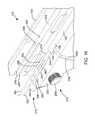
- FIGS. 14-16respectively show isometric assembled, isometric exploded and magnified isometric views of the applicator 102 with a handheld unit 220 formed in accordance with exemplary embodiments of the invention.
- the handheld unit 220comprises a pistol grip 230 and a support member 232 that extends transversely to the pistol grip 230 .
- the support 232comprises a hinged cover 234 having a closed position ( FIG. 14 ) and an opened position ( FIG. 15 ).
- a bore 236is formed in the support 232 and/or the cover 234 and is sized to receive the shaft 104 , as shown in FIG. 16 .
- the shaft 104is securely held within the bore 236 when the cover 234 is in the closed position such that inadvertent movement of the shaft 104 in the longitudinal direction during normal handling of the applicator 102 is prevented.
- the support 232 and/or the cover 234includes a shoulder portion 238 at a proximal end 240 of the bore 236 that prevents the shaft 104 from sliding toward the rear 242 of the support 232 along the longitudinal axis.
- the support 232 and/or the cover 234comprise a channel 244 that is configured to receive the laser fiber 162 , as best shown in FIG. 16 .
- the channel 244extends to the shoulder portion 238 where it receives the laser fiber 162 where it exits the shaft 104 .
- the channel 244extends from the shoulder 238 out the rear end of the support 232 where it can be coupled to the laser system 160 in a conventional manner.
- FIG. 16Another embodiment of the handheld unit 220 comprises a channel 246 formed in the support 232 and/or the cover 234 , as best shown in FIG. 16 .
- the channel 246extends from the shoulder portion 238 out the rear end 242 of the support 232 .
- the channel 246is configured to receive the viewing fiber 220 as it exits the proximal end 106 of the shaft 104 and allows the viewing fiber 202 to extend out the rear end 242 of the support member 232 where it can be connected to the viewing system 208 .
- the handheld unit 220includes a channel 248 configured to receive conduit 250 that is coupled to the fluid input port 140 , as shown in FIG. 16 .
- the channel 248extends through the support 232 and the pistol grip 230 .
- the exposed end of the conduit 250may be coupled to the flow meter 213 or pump 144 using conventional means.
- the handheld unit 220includes the one or more laser fiber positioning components 180 .
- the laser fiber positioning components 180comprise a thumb wheel 252 that is coupled to a roller 252 through a gear, axle, or other suitable arrangement, as shown in FIG. 15 .
- the roller 252engages the laser fiber 162 through a slot 256 in the support 232 , as shown in FIG. 16 .
- One embodiment of the roller 252comprises an exterior surface that comprises rubber or other suitable material that provides sufficient frictional resistance with the exterior of the laser fiber 162 to grip the laser fiber 162 and inhibit sliding contact between the roller 254 and the laser fiber 162 .
- Rotation of the thumb wheel 252rotates the roller 254 , which drives the longitudinal movement of the laser fiber 162 in either the forward or rearward direction relative to the handheld unit 220 and the shaft 104 .
- the roller 254drives the longitudinal movement of the laser fiber 162 in either the forward or rearward direction relative to the handheld unit 220 and the shaft 104 .
- One embodiment of the one or more viewing fiber positioning components 210includes a thumb wheel 258 and a roller 260 that operate similarly to the thumb wheel 252 and roller 254 described above to move the viewing fiber 202 in the longitudinal direction relative to the handheld unit 220 , the shaft 104 and the balloon 110 .
- the thumb wheel 258is coupled to the roller 260 through a suitable arrangement, such as a gear.
- the roller 260is exposed to engage the viewing fiber 202 through a slot 262 in the support 232 .
- the roller 260comprises an exterior surface that is formed of a material (e.g., rubber) that generates sufficient frictional resistance with the viewing fiber 202 to inhibit sliding contact between the roller 260 and the viewing fiber 202 as the roller 260 is rotated.
- Rotation of the thumb wheel 258causes the roller 260 to rotate, which drives the viewing fiber in the longitudinal direction relative to the handheld unit 220 , the shaft 104 and the balloon 110 .
- the longitudinal position of the distal end 204 of the viewing fiber 202can be positioned as desired relative to the balloon 110 using the thumb wheel 258 .
- the handheld unit 220comprises one or more viewing fiber positioning components 210 that are configured to rotate the viewing fiber 202 about its longitudinal axis.
- One embodiment of the components 210comprise a rotatable member 264 , such as a thumb wheel, and a roller 266 .
- the rotatable member 264is coupled to the roller 266 through an axle, gear, or other suitable arrangement, such that rotation of the member 264 causes the roller 266 to rotate.
- the axes of rotation of the member 264 and the roller 266are parallel to the longitudinal axis of the viewing fiber 202 and the channel 246 .
- the roller 266engages the viewing fiber 202 through a slot 268 .
- the exterior surface of the roller 266is formed of a material (e.g., rubber) that produces sufficient frictional resistance with the viewing fiber 202 to inhibit sliding contact with the viewing fiber 202 as the roller 266 rotates.
- the rotation of the member 264causes the roller 266 to rotate, which drives the rotation of the viewing fiber 202 about its longitudinal axis. This allows the distal end 204 of the viewing fiber 202 to be rotated as desired within the balloon 110 .
- One embodiment of the one or more laser fiber positioning components 180includes components that are similar to the rotatable member 264 and the roller 266 that can be used to rotate the laser fiber 162 about its longitudinal axis.
- the handheld unit 220includes the laser actuator 222 in the form of a trigger 270 that is mounted to the support 232 .
- actuation of the trigger 270directs the laser system 160 to transmit laser light through the laser fiber 162 for discharge through the dispenser 166 .
- the shaft 104 , the balloon 110 , the laser fiber 162 , the viewing fiber 202 , the tubing 250 , and/or the port 140form a disposable group of components.
- one or more of these componentsare provided as a kit in sterilized packaging.
- one or more of these componentscome pre-assembled.
- a disposable assemblymay comprise the shaft 104 , the balloon 110 , the laser fiber 162 and the tubing, as shown in FIG. 15 , that is ready for installation within the handheld unit 220 .
- One or more of the other components described above, such as the seal 142may also be included the disposable assembly.
- Additional embodiments of the inventioninclude methods of ablating tissue of a patient, or performing another laser treatment, using the system 100 .
- the system 100 formed in accordance with one or more embodiments described aboveis provided and the system is prepared for the ablation operation. This may involve the providing of the disposable assembly described above in, for example, sterilized packaging. The disposable assembly is then installed in the handheld unit 202 .
- the laser fiber 162is connected to the laser system 160 .
- the viewing fiber 202(if present) is connected to the viewing console 208 .
- the tubing 250is fluidically coupled to the pump 144 .
- connectionsare made between the one or more sensors 212 and the controller 214 .
- a coatingsuch as an adjuvant, is applied to the exterior surface of the balloon 110 , which is placed in contact with the target tissue when the balloon 110 is inflated within the cavity of the patient.
- the adjuvantis designed to enhance laser tissue ablation by absorbing the wavelength of laser light that will be applied to the tissue.
- Embodiments of the coatingare described in U.S. patent application Ser. No. 12/468,668 filed May 19, 2009 entitled “ADJUVANT ENHANCED ABLATION,” which is incorporated herein by reference in its entirety.
- the balloon 110is placed in the deflated state 124 and the distal end 108 of the shaft 104 is fed into the cavity of the patent, such as the uterus, where the target tissue is located.
- the cavityis visually inspected using the viewing fiber 202 .
- the balloon 110is inflated within the cavity by pumping either fluid or gas through the tubing 250 and the port 140 , such as using the pump 144 .
- the inflated state 126 of the balloonengages the interior wall of the cavity, such as illustrated in FIG. 5 .
- the cavity and the inflated balloon 110are inspected using the viewing fiber 202 . This involves moving the distal end 204 of the viewing fiber 202 axially and/or angularly using the one or more viewing fiber positioning components 210 .
- the markings 139 on the balloonare imaged or viewed using the viewing fiber 202 .
- the markingsindicate whether the balloon 110 is properly inflated and/or positioned within the cavity of the patient.
- the balloon 110is deflated, repositioned and inflated again until the markings 139 indicate that the balloon 110 is fully inflated and/or in the desired position within the cavity.
- the laser fiber 162is positioned as desired relative to the shaft 104 and the balloon 110 using the one or more laser fiber positioning components 180 . This may involve moving the distal end 168 axially, angularly, or along an arc.
- the laser system 160is activated to transmit laser light 164 through the laser fiber 162 and out the dispenser 166 to ablate the targeted tissue. In one embodiment, this activation of the laser system is responsive to the actuation of the laser actuator 222 . In one embodiment, the targeted tissues are inspected using the viewing fiber 202 .
- the dispenser 166 , the distal end 108 of the shaft 104 , and/or the balloon 110are configured to provide substantially uniform transmission of the laser light 164 .
- the dispenser 166 , the distal end 108 of the shaft 104 , and/or the balloon 110are configured to provide non-uniform transmission of the laser light to control the exposure of the target tissue to the laser light.
- a coatingis applied to the shaft 104 and/or the interior of the balloon 110 to control the transmission of the laser light therethrough.
- the distal end 168 of the laser fiber 162is moved along an arc and/or axially to another position relative to the shaft 104 and the balloon 110 to target other tissue within the cavity of the patient.
- a flow of fluid or gasis circulated through the balloon 110 .
- the flow of fluid or gasis regulated responsive to a temperature signal from a temperature sensor 212 .
- the balloon 110is returned to its deflated state 124 and the balloon 110 , the shaft 104 , the laser fiber 162 and other components of the system (e.g., the viewing fiber 202 ) are removed from the cavity.
- the disposable componentscan then be detached from the laser system 160 , the pump 144 and the viewing console 208 , removed from the applicator 102 and discarded.
Landscapes
- Health & Medical Sciences (AREA)
- Surgery (AREA)
- Physics & Mathematics (AREA)
- Life Sciences & Earth Sciences (AREA)
- Engineering & Computer Science (AREA)
- Medical Informatics (AREA)
- Nuclear Medicine, Radiotherapy & Molecular Imaging (AREA)
- Electromagnetism (AREA)
- Optics & Photonics (AREA)
- Biomedical Technology (AREA)
- Heart & Thoracic Surgery (AREA)
- Otolaryngology (AREA)
- Molecular Biology (AREA)
- Animal Behavior & Ethology (AREA)
- General Health & Medical Sciences (AREA)
- Public Health (AREA)
- Veterinary Medicine (AREA)
- Laser Surgery Devices (AREA)
Abstract
Description
Claims (12)
Priority Applications (4)
| Application Number | Priority Date | Filing Date | Title |
|---|---|---|---|
| US13/152,825US8936592B2 (en) | 2010-06-03 | 2011-06-03 | Laser tissue ablation system |
| US13/330,038US8876804B2 (en) | 2010-12-17 | 2011-12-19 | Ablation device |
| US14/521,831US9433467B2 (en) | 2010-06-03 | 2014-10-23 | Laser tissue ablation system |
| US15/209,120US10105184B2 (en) | 2010-06-03 | 2016-07-13 | Laser tissue ablation system |
Applications Claiming Priority (2)
| Application Number | Priority Date | Filing Date | Title |
|---|---|---|---|
| US35112710P | 2010-06-03 | 2010-06-03 | |
| US13/152,825US8936592B2 (en) | 2010-06-03 | 2011-06-03 | Laser tissue ablation system |
Related Child Applications (2)
| Application Number | Title | Priority Date | Filing Date |
|---|---|---|---|
| US13/330,038Continuation-In-PartUS8876804B2 (en) | 2010-12-17 | 2011-12-19 | Ablation device |
| US14/521,831ContinuationUS9433467B2 (en) | 2010-06-03 | 2014-10-23 | Laser tissue ablation system |
Publications (2)
| Publication Number | Publication Date |
|---|---|
| US20110301584A1 US20110301584A1 (en) | 2011-12-08 |
| US8936592B2true US8936592B2 (en) | 2015-01-20 |
Family
ID=45065026
Family Applications (3)
| Application Number | Title | Priority Date | Filing Date |
|---|---|---|---|
| US13/152,825Expired - Fee RelatedUS8936592B2 (en) | 2010-06-03 | 2011-06-03 | Laser tissue ablation system |
| US14/521,831ActiveUS9433467B2 (en) | 2010-06-03 | 2014-10-23 | Laser tissue ablation system |
| US15/209,120Active2031-06-26US10105184B2 (en) | 2010-06-03 | 2016-07-13 | Laser tissue ablation system |
Family Applications After (2)
| Application Number | Title | Priority Date | Filing Date |
|---|---|---|---|
| US14/521,831ActiveUS9433467B2 (en) | 2010-06-03 | 2014-10-23 | Laser tissue ablation system |
| US15/209,120Active2031-06-26US10105184B2 (en) | 2010-06-03 | 2016-07-13 | Laser tissue ablation system |
Country Status (1)
| Country | Link |
|---|---|
| US (3) | US8936592B2 (en) |
Cited By (10)
| Publication number | Priority date | Publication date | Assignee | Title |
|---|---|---|---|---|
| US9433467B2 (en) | 2010-06-03 | 2016-09-06 | Boston Scientific Scimed, Inc. | Laser tissue ablation system |
| US10687894B2 (en)* | 2010-12-29 | 2020-06-23 | Biolitec Unternehmensbeteiligungs Ii Ag | Vaginal remodeling/rejuvenation device and method |
| US11013558B2 (en) | 2018-02-27 | 2021-05-25 | H. Christopher Redkey | Method and apparatus for endo fistula laser therapy |
| US11160597B2 (en) | 2010-11-09 | 2021-11-02 | Aegea Medical Inc. | Positioning method and apparatus for delivering vapor to the uterus |
| US11207118B2 (en) | 2007-07-06 | 2021-12-28 | Tsunami Medtech, Llc | Medical system and method of use |
| US11213338B2 (en) | 2007-08-23 | 2022-01-04 | Aegea Medical Inc. | Uterine therapy device and method |
| US11219479B2 (en) | 2014-05-22 | 2022-01-11 | Aegea Medical Inc. | Integrity testing method and apparatus for delivering vapor to the uterus |
| US11331037B2 (en) | 2016-02-19 | 2022-05-17 | Aegea Medical Inc. | Methods and apparatus for determining the integrity of a bodily cavity |
| US11497089B2 (en) | 2017-06-20 | 2022-11-08 | Aegea Medical Inc. | Induction coil assembly for uterine ablation and method |
| US11849991B2 (en) | 2011-10-07 | 2023-12-26 | Aegea Medical Inc. | Integrity testing method and apparatus for delivering vapor to the uterus |
Families Citing this family (32)
| Publication number | Priority date | Publication date | Assignee | Title |
|---|---|---|---|---|
| US6420975B1 (en) | 1999-08-25 | 2002-07-16 | Donnelly Corporation | Interior rearview mirror sound processing system |
| EP2403424A4 (en)* | 2009-03-05 | 2013-11-06 | Cynosure Inc | Thermal surgery safety apparatus and method |
| IT1405000B1 (en)* | 2010-02-04 | 2013-12-16 | El En Spa | DEVICE FOR THE TREATMENT OF THE VAGINAL CHANNEL AND ITS APPARATUS |
| US8876804B2 (en) | 2010-12-17 | 2014-11-04 | Ams Research Corporation | Ablation device |
| US9220887B2 (en) | 2011-06-09 | 2015-12-29 | Astora Women's Health LLC | Electrode lead including a deployable tissue anchor |
| US9750503B2 (en)* | 2013-07-11 | 2017-09-05 | Covidien Lp | Methods and devices for performing a surgical anastomosis |
| CN103462688B (en)* | 2013-08-29 | 2016-02-03 | 珠海市司迈科技有限公司 | Laser fiber sheath and use the operator of this laser fiber sheath |
| EP3203922B1 (en) | 2014-10-07 | 2018-04-18 | Hologic, Inc. | Endometrial lining tissue treatment device |
| US11826097B2 (en) | 2015-11-18 | 2023-11-28 | Cyclone Biosciences, Llc | Forming radial emissions from optical fibers |
| US10092356B2 (en)* | 2015-11-18 | 2018-10-09 | InnovaQuartz LLC | Radial emissions from optical fibers |
| US11344365B2 (en) | 2016-01-05 | 2022-05-31 | Cardiofocus, Inc. | Ablation system with automated sweeping ablation energy element |
| CN109561929A (en)* | 2016-06-06 | 2019-04-02 | 纽乌罗有限公司 | Device for far field bipolar ablation |
| EP4186450B1 (en)* | 2016-12-09 | 2025-01-22 | St. Jude Medical, Cardiology Division, Inc. | Pulmonary vein isolation balloon catheter |
| EP3740147B1 (en) | 2018-01-15 | 2024-03-27 | Cardiofocus, Inc. | Ablation system with automated ablation energy element |
| US10912612B2 (en) | 2018-01-17 | 2021-02-09 | Gyrus Acmi, Inc. | System and device for treating body tissue |
| US10765883B2 (en) | 2018-06-26 | 2020-09-08 | Zlasers Ltd. | Vaginal tightening and treatment of wrinkles |
| JP2020089480A (en)* | 2018-12-04 | 2020-06-11 | 住友電気工業株式会社 | Catheter device, catheter device control method, catheter device control program, and balloon catheter |
| AU2019458295B2 (en) | 2019-07-24 | 2025-02-27 | Medlogical Innovations Pty Ltd | System with cooling fluid for interstitial laser therapy |
| JP2022543429A (en) | 2019-08-05 | 2022-10-12 | ジャイラス エーシーエムアイ インク ディー/ビー/エー オリンパス サージカル テクノロジーズ アメリカ | fiber optic assembly |
| CN114630634B (en) | 2019-08-05 | 2025-09-12 | 捷锐士阿希迈公司(以奥林巴斯美国外科技术名义) | Endoscopic laser energy delivery system and method of use |
| US11819195B2 (en) | 2019-08-05 | 2023-11-21 | Gyrus Acmi, Inc. | Signal coordinated delivery of laser therapy |
| CN119655873A (en) | 2019-08-05 | 2025-03-21 | 捷锐士阿希迈公司(以奥林巴斯美国外科技术名义) | Medical laser system and method for operating a medical laser system |
| US11523865B2 (en) | 2019-08-05 | 2022-12-13 | Gyrus Acmi, Inc. | Target identification with optical feedback signal splitter |
| CN114401661A (en) | 2019-08-05 | 2022-04-26 | 捷锐士阿希迈公司(以奥林巴斯美国外科技术名义) | Endoscopic laser system with laser interlock |
| US12279812B2 (en) | 2019-08-05 | 2025-04-22 | Gyrus Acmi, Inc. | Laser fiber varying lateral position and intensity |
| US11957410B2 (en) | 2019-08-05 | 2024-04-16 | Gyrus Acmi, Inc. | Laser fiber-to-target distance control |
| WO2021026161A1 (en) | 2019-08-05 | 2021-02-11 | Gyrus Acmi, Inc., D.B.A. Olympus Surgical Technologies America | Laser control using a spectrometer |
| US12036418B2 (en)* | 2019-12-31 | 2024-07-16 | Gyrus Acmi, Inc. | Surgical devices for treating body tissue and diagnosing patients |
| US12357382B2 (en) | 2020-07-21 | 2025-07-15 | Gyrus Acmi, Inc. | Laser treatment using acoustic feedback |
| US11882994B2 (en) | 2020-07-24 | 2024-01-30 | Gyrus Acmi, Inc. | Systems and methods for image reconstruction and endoscopic tracking |
| DE112021004135T5 (en) | 2020-08-05 | 2023-05-17 | Gyrus Acmi, Inc. D/B/A Olympus Surgical Technologies America | IDENTIFICATION OF THE COMPOSITION OF AN ANATOMIC TARGET |
| CN116056621A (en) | 2020-08-05 | 2023-05-02 | 捷锐士阿希迈公司(以奥林巴斯美国外科技术名义) | Depth and contour detection of anatomical targets |
Citations (62)
| Publication number | Priority date | Publication date | Assignee | Title |
|---|---|---|---|---|
| US4998930A (en)* | 1988-08-03 | 1991-03-12 | Phototherapeutic Systems | Intracavity laser phototherapy method |
| US5061265A (en) | 1989-06-20 | 1991-10-29 | University Of Florida | Laser treatment apparatus and method |
| US5074632A (en) | 1990-03-07 | 1991-12-24 | Health Research, Inc. | Fiber optic diffusers and methods for manufacture of the same |
| US5102402A (en) | 1991-01-04 | 1992-04-07 | Medtronic, Inc. | Releasable coatings on balloon catheters |
| US5125925A (en) | 1988-08-03 | 1992-06-30 | Photoradiation Systems | Intracavity laser catheter with sensing fiber |
| US5269777A (en) | 1990-11-01 | 1993-12-14 | Pdt Systems, Inc. | Diffusion tip for optical fibers |
| US5409483A (en) | 1993-01-22 | 1995-04-25 | Jeffrey H. Reese | Direct visualization surgical probe |
| US5411016A (en) | 1994-02-22 | 1995-05-02 | Scimed Life Systems, Inc. | Intravascular balloon catheter for use in combination with an angioscope |
| US5428699A (en) | 1993-07-02 | 1995-06-27 | Laserscope | Probe having optical fiber for laterally directing laser beam |
| US5431647A (en) | 1994-07-13 | 1995-07-11 | Pioneer Optics Company | Fiberoptic cylindrical diffuser |
| US5458595A (en) | 1993-12-16 | 1995-10-17 | The Regents Of The University Of California | Vaginal speculum for photodynamic therapy and method of using the same |
| US5530780A (en) | 1993-12-20 | 1996-06-25 | Lederle (Japan), Ltd. | Fiber optic laser conducting and diffusion device |
| US5533508A (en) | 1991-10-31 | 1996-07-09 | Pdt Systems, Inc. | Vivo dosimeter for photodynamic therapy |
| US5569240A (en) | 1990-06-08 | 1996-10-29 | Kelsey, Inc. | Apparatus for interstitial laser therapy |
| US5593405A (en) | 1994-07-16 | 1997-01-14 | Osypka; Peter | Fiber optic endoscope |
| US5645562A (en) | 1995-03-13 | 1997-07-08 | Cordis Corporation | Balloon catheter with light conductor |
| US5695583A (en) | 1994-03-25 | 1997-12-09 | Novartis Corporation | Light diffuser and process for the manufacturing of a light diffuser |
| US5728092A (en) | 1996-03-07 | 1998-03-17 | Miravant Systems, Inc. | Light delivery catheter |
| US5730700A (en) | 1992-05-14 | 1998-03-24 | The United States Of America As Represented By The Department Of Health And Human Service | Method for measuring incident light in a body cavity |
| US5733277A (en) | 1994-06-22 | 1998-03-31 | Pallarito; Allan L. | Optical fibre and laser for removal of arterial or vascular obstructions |
| US5807390A (en) | 1992-04-24 | 1998-09-15 | Surgical Laser Technologies, Inc. | Light energy emitting probe with light-affecting inclusions distributed throughout |
| US5824005A (en) | 1995-08-22 | 1998-10-20 | Board Of Regents, The University Of Texas System | Maneuverable electrophysiology catheter for percutaneous or intraoperative ablation of cardiac arrhythmias |
| US5854422A (en) | 1996-07-10 | 1998-12-29 | K-Line Industries, Inc. | Ultrasonic detector |
| US5876426A (en) | 1996-06-13 | 1999-03-02 | Scimed Life Systems, Inc. | System and method of providing a blood-free interface for intravascular light delivery |
| US5891082A (en) | 1995-03-15 | 1999-04-06 | Cordis Corporation | Ballon catheter with light-conductive basic body |
| US5891136A (en) | 1996-01-19 | 1999-04-06 | Ep Technologies, Inc. | Expandable-collapsible mesh electrode structures |
| US5911720A (en) | 1996-11-26 | 1999-06-15 | Ep Technologies, Inc. | Ablation catheter with segmented tip |
| US5947958A (en) | 1995-09-14 | 1999-09-07 | Conceptus, Inc. | Radiation-transmitting sheath and methods for its use |
| US5997571A (en) | 1997-12-17 | 1999-12-07 | Cardiofocus, Inc. | Non-occluding phototherapy probe stabilizers |
| US6013053A (en) | 1996-05-17 | 2000-01-11 | Qlt Photo Therapeutics Inc. | Balloon catheter for photodynamic therapy |
| US6027524A (en) | 1997-07-07 | 2000-02-22 | Petit; Michael G. | Implantable illuminator for photodynamic therapy of the breast and method |
| US6096030A (en) | 1997-09-23 | 2000-08-01 | Pharmacyclics, Inc. | Light delivery catheter and PDT treatment method |
| US6146409A (en) | 1996-05-20 | 2000-11-14 | Bergein F. Overholt | Therapeutic methods and devices for irradiating columnar environments |
| US6270492B1 (en) | 1994-09-09 | 2001-08-07 | Cardiofocus, Inc. | Phototherapeutic apparatus with diffusive tip assembly |
| US6391052B2 (en) | 1994-04-29 | 2002-05-21 | Scimed Life Systems, Inc. | Stent with collagen |
| US6398778B1 (en) | 1999-06-18 | 2002-06-04 | Photonics Research Ontario | Optical fiber diffuser |
| US6423055B1 (en) | 1999-07-14 | 2002-07-23 | Cardiofocus, Inc. | Phototherapeutic wave guide apparatus |
| US6482197B2 (en) | 1998-01-07 | 2002-11-19 | Vasca, Inc. | Methods and apparatus for inhibiting infection of subcutaneously implanted devices |
| US20020193850A1 (en)* | 1993-09-29 | 2002-12-19 | Selman Steven H. | Use of photodynamic therapy to treat prostatic tissue |
| US6522806B1 (en) | 2001-02-16 | 2003-02-18 | Ethicon Endo-Surgury, Inc. | Optical fiber including a diffuser portion and continuous sleeve for the transmission of light |
| US6524274B1 (en) | 1990-12-28 | 2003-02-25 | Scimed Life Systems, Inc. | Triggered release hydrogel drug delivery system |
| US6572609B1 (en) | 1999-07-14 | 2003-06-03 | Cardiofocus, Inc. | Phototherapeutic waveguide apparatus |
| US6616653B2 (en) | 2000-04-14 | 2003-09-09 | American Medical Systems, Inc. | Method and apparatus for coagulation of superficial blood vessels in bladder and proximal urethra |
| US6708056B2 (en) | 2000-04-25 | 2004-03-16 | Impres Medical, Inc. | Method and apparatus for creating intrauterine adhesions |
| US6706004B2 (en) | 2001-05-31 | 2004-03-16 | Infraredx, Inc. | Balloon catheter |
| US20040082859A1 (en)* | 2002-07-01 | 2004-04-29 | Alan Schaer | Method and apparatus employing ultrasound energy to treat body sphincters |
| US20040133254A1 (en) | 2003-01-07 | 2004-07-08 | Fred Sterzer | Inflatable balloon catheter structural designs and methods for treating diseased tissue of a patient |
| US6796972B1 (en) | 2000-07-14 | 2004-09-28 | Edwards Lifesciences Llc | Catheter anchoring balloon structure with irrigation |
| US6829411B2 (en) | 2000-09-01 | 2004-12-07 | Syntec, Inc. | Wide angle light diffusing optical fiber tip |
| US6899706B2 (en) | 2002-01-09 | 2005-05-31 | Inolase 2002 Ltd. | Isotopic laser for the oral cavity and use of the same |
| US20050255039A1 (en) | 1998-06-26 | 2005-11-17 | Pro Surg, Inc., A California Corporation | Gel injection treatment of breast, fibroids & endometrial ablation |
| US6986764B2 (en) | 2000-12-15 | 2006-01-17 | Laserscope | Method and system for photoselective vaporization of the prostate, and other tissue |
| US7112195B2 (en) | 2003-04-21 | 2006-09-26 | Cynosure, Inc. | Esophageal lesion treatment method |
| US7131963B1 (en) | 2002-06-27 | 2006-11-07 | Advanced Cardiovascular Systems, Inc. | Catheters and methods of using catheters |
| US7135034B2 (en) | 2003-11-14 | 2006-11-14 | Lumerx, Inc. | Flexible array |
| US20070032783A1 (en)* | 2004-03-23 | 2007-02-08 | Cryocath Technologies Inc. | Method and apparatus for inflating and deflating balloon catheters |
| US20070282403A1 (en)* | 2006-02-01 | 2007-12-06 | The General Hospital Corporation | Methods and systems for providing electromagnetic radiation to at least one portion of a sample using conformal laser therapy procedures |
| US20080039828A1 (en) | 2006-08-10 | 2008-02-14 | Jimenez Jose W | Laser Tissue Vaporization |
| US20090138000A1 (en)* | 2003-12-22 | 2009-05-28 | Vancelette David W | Cryosurgical devices and methods for endometrial ablation |
| US20100298757A1 (en) | 2009-05-19 | 2010-11-25 | Ams Research Corporation | Adjuvant enhanced ablation |
| US7905874B2 (en) | 2004-04-16 | 2011-03-15 | Kyphon Sarl | Spinal diagnostic methods and apparatus |
| US20120157981A1 (en) | 2010-12-17 | 2012-06-21 | Evans Douglas L | Ablation device |
Family Cites Families (28)
| Publication number | Priority date | Publication date | Assignee | Title |
|---|---|---|---|---|
| US4976710A (en)* | 1987-01-28 | 1990-12-11 | Mackin Robert A | Working well balloon method |
| US5437660A (en)* | 1991-12-30 | 1995-08-01 | Trimedyne, Inc. | Tissue ablation and a lateral-lasing fiber optic device therefor |
| US5344419A (en)* | 1993-04-23 | 1994-09-06 | Wayne State University | Apparatus and method for making a diffusing tip in a balloon catheter system |
| US5415654A (en) | 1993-10-05 | 1995-05-16 | S.L.T. Japan Co., Ltd. | Laser balloon catheter apparatus |
| US5756145A (en) | 1995-11-08 | 1998-05-26 | Baylor College Of Medicine | Durable, Resilient and effective antimicrobial coating for medical devices and method of coating therefor |
| US5729092A (en) | 1996-08-22 | 1998-03-17 | Thomson Consumer Electronics, Inc. | CRT focus mask degaussing arrangement responsive to a breakdown event |
| US6500174B1 (en)* | 1997-07-08 | 2002-12-31 | Atrionix, Inc. | Circumferential ablation device assembly and methods of use and manufacture providing an ablative circumferential band along an expandable member |
| US6837885B2 (en) | 1998-05-22 | 2005-01-04 | Scimed Life Systems, Inc. | Surgical probe for supporting inflatable therapeutic devices in contact with tissue in or around body orifices and within tumors |
| US6379347B1 (en) | 1998-05-28 | 2002-04-30 | Terumo Kabushiki Kaisha | Energy irradiation apparatus |
| US6471692B1 (en)* | 1998-06-24 | 2002-10-29 | Laser Industries Ltd. | System and method for manipulating movement of an energy emitting device within a body cavity |
| US6398779B1 (en) | 1998-10-23 | 2002-06-04 | Sherwood Services Ag | Vessel sealing system |
| US6432102B2 (en)* | 1999-03-15 | 2002-08-13 | Cryovascular Systems, Inc. | Cryosurgical fluid supply |
| US6648879B2 (en)* | 1999-02-24 | 2003-11-18 | Cryovascular Systems, Inc. | Safety cryotherapy catheter |
| US6514245B1 (en)* | 1999-03-15 | 2003-02-04 | Cryovascular Systems, Inc. | Safety cryotherapy catheter |
| AU2001233098A1 (en)* | 2000-01-27 | 2001-08-07 | Sterilis, Inc. | Cavity enlarger method and apparatus |
| US6602246B1 (en)* | 2000-08-18 | 2003-08-05 | Cryovascular Systems, Inc. | Cryotherapy method for detecting and treating vulnerable plaque |
| US6955174B2 (en)* | 2000-08-18 | 2005-10-18 | Uryovascular Systems, Inc. | Cryotherapy method for detecting and treating vulnerable plaque |
| US6517531B2 (en)* | 2001-04-27 | 2003-02-11 | Scimed Life Systems, Inc. | Medical suction device |
| US6786900B2 (en)* | 2001-08-13 | 2004-09-07 | Cryovascular Systems, Inc. | Cryotherapy methods for treating vessel dissections and side branch occlusion |
| EP1513440A2 (en)* | 2002-05-30 | 2005-03-16 | The Board of Trustees of The Leland Stanford Junior University | Apparatus and method for coronary sinus access |
| US6953458B2 (en)* | 2002-12-20 | 2005-10-11 | Trimedyne, Inc. | Device and method for delivery of long wavelength laser energy to a tissue site |
| US20050203496A1 (en)* | 2004-03-12 | 2005-09-15 | Ritchie Paul G. | Medical apparatus and method useful for thermal treatment of a lumen |
| US7559925B2 (en)* | 2006-09-15 | 2009-07-14 | Acclarent Inc. | Methods and devices for facilitating visualization in a surgical environment |
| US8190238B2 (en)* | 2005-12-09 | 2012-05-29 | Hansen Medical, Inc. | Robotic catheter system and methods |
| US20080281317A1 (en)* | 2007-05-10 | 2008-11-13 | Fred Gobel | Endometrial Ablation catheter |
| US8241273B2 (en)* | 2009-01-09 | 2012-08-14 | Ncontact Surgical, Inc. | Method and devices for coagulation of tissue |
| US8876807B2 (en) | 2009-01-19 | 2014-11-04 | W. L. Gore & Associates, Inc. | Forced deployment sequence |
| US8936592B2 (en) | 2010-06-03 | 2015-01-20 | Ams Research Corporation | Laser tissue ablation system |
- 2011
- 2011-06-03USUS13/152,825patent/US8936592B2/ennot_activeExpired - Fee Related
- 2014
- 2014-10-23USUS14/521,831patent/US9433467B2/enactiveActive
- 2016
- 2016-07-13USUS15/209,120patent/US10105184B2/enactiveActive
Patent Citations (70)
| Publication number | Priority date | Publication date | Assignee | Title |
|---|---|---|---|---|
| US5125925A (en) | 1988-08-03 | 1992-06-30 | Photoradiation Systems | Intracavity laser catheter with sensing fiber |
| US4998930A (en)* | 1988-08-03 | 1991-03-12 | Phototherapeutic Systems | Intracavity laser phototherapy method |
| US5061265A (en) | 1989-06-20 | 1991-10-29 | University Of Florida | Laser treatment apparatus and method |
| US5074632A (en) | 1990-03-07 | 1991-12-24 | Health Research, Inc. | Fiber optic diffusers and methods for manufacture of the same |
| US5569240A (en) | 1990-06-08 | 1996-10-29 | Kelsey, Inc. | Apparatus for interstitial laser therapy |
| US5269777A (en) | 1990-11-01 | 1993-12-14 | Pdt Systems, Inc. | Diffusion tip for optical fibers |
| US6524274B1 (en) | 1990-12-28 | 2003-02-25 | Scimed Life Systems, Inc. | Triggered release hydrogel drug delivery system |
| US5102402A (en) | 1991-01-04 | 1992-04-07 | Medtronic, Inc. | Releasable coatings on balloon catheters |
| US5533508A (en) | 1991-10-31 | 1996-07-09 | Pdt Systems, Inc. | Vivo dosimeter for photodynamic therapy |
| US5807390A (en) | 1992-04-24 | 1998-09-15 | Surgical Laser Technologies, Inc. | Light energy emitting probe with light-affecting inclusions distributed throughout |
| US5730700A (en) | 1992-05-14 | 1998-03-24 | The United States Of America As Represented By The Department Of Health And Human Service | Method for measuring incident light in a body cavity |
| US5409483A (en) | 1993-01-22 | 1995-04-25 | Jeffrey H. Reese | Direct visualization surgical probe |
| US5428699A (en) | 1993-07-02 | 1995-06-27 | Laserscope | Probe having optical fiber for laterally directing laser beam |
| US20020193850A1 (en)* | 1993-09-29 | 2002-12-19 | Selman Steven H. | Use of photodynamic therapy to treat prostatic tissue |
| US5458595A (en) | 1993-12-16 | 1995-10-17 | The Regents Of The University Of California | Vaginal speculum for photodynamic therapy and method of using the same |
| US5530780A (en) | 1993-12-20 | 1996-06-25 | Lederle (Japan), Ltd. | Fiber optic laser conducting and diffusion device |
| US7169140B1 (en) | 1994-02-22 | 2007-01-30 | Boston Scientific Scimed, Inc. | Methods of using an intravascular balloon catheter in combination with an angioscope |
| US5411016A (en) | 1994-02-22 | 1995-05-02 | Scimed Life Systems, Inc. | Intravascular balloon catheter for use in combination with an angioscope |
| US5695583A (en) | 1994-03-25 | 1997-12-09 | Novartis Corporation | Light diffuser and process for the manufacturing of a light diffuser |
| US6391052B2 (en) | 1994-04-29 | 2002-05-21 | Scimed Life Systems, Inc. | Stent with collagen |
| US5733277A (en) | 1994-06-22 | 1998-03-31 | Pallarito; Allan L. | Optical fibre and laser for removal of arterial or vascular obstructions |
| US5431647A (en) | 1994-07-13 | 1995-07-11 | Pioneer Optics Company | Fiberoptic cylindrical diffuser |
| US5593405A (en) | 1994-07-16 | 1997-01-14 | Osypka; Peter | Fiber optic endoscope |
| US6270492B1 (en) | 1994-09-09 | 2001-08-07 | Cardiofocus, Inc. | Phototherapeutic apparatus with diffusive tip assembly |
| US5645562A (en) | 1995-03-13 | 1997-07-08 | Cordis Corporation | Balloon catheter with light conductor |
| US5891082A (en) | 1995-03-15 | 1999-04-06 | Cordis Corporation | Ballon catheter with light-conductive basic body |
| US5824005A (en) | 1995-08-22 | 1998-10-20 | Board Of Regents, The University Of Texas System | Maneuverable electrophysiology catheter for percutaneous or intraoperative ablation of cardiac arrhythmias |
| US5947958A (en) | 1995-09-14 | 1999-09-07 | Conceptus, Inc. | Radiation-transmitting sheath and methods for its use |
| US5891136A (en) | 1996-01-19 | 1999-04-06 | Ep Technologies, Inc. | Expandable-collapsible mesh electrode structures |
| US5728092A (en) | 1996-03-07 | 1998-03-17 | Miravant Systems, Inc. | Light delivery catheter |
| US6013053A (en) | 1996-05-17 | 2000-01-11 | Qlt Photo Therapeutics Inc. | Balloon catheter for photodynamic therapy |
| US6086558A (en) | 1996-05-17 | 2000-07-11 | Qlt Phototherapeutics, Inc. | Balloon catheter for photodynamic therapy |
| US6146409A (en) | 1996-05-20 | 2000-11-14 | Bergein F. Overholt | Therapeutic methods and devices for irradiating columnar environments |
| US5876426A (en) | 1996-06-13 | 1999-03-02 | Scimed Life Systems, Inc. | System and method of providing a blood-free interface for intravascular light delivery |
| US5854422A (en) | 1996-07-10 | 1998-12-29 | K-Line Industries, Inc. | Ultrasonic detector |
| US5911720A (en) | 1996-11-26 | 1999-06-15 | Ep Technologies, Inc. | Ablation catheter with segmented tip |
| US6027524A (en) | 1997-07-07 | 2000-02-22 | Petit; Michael G. | Implantable illuminator for photodynamic therapy of the breast and method |
| US6096030A (en) | 1997-09-23 | 2000-08-01 | Pharmacyclics, Inc. | Light delivery catheter and PDT treatment method |
| US5997571A (en) | 1997-12-17 | 1999-12-07 | Cardiofocus, Inc. | Non-occluding phototherapy probe stabilizers |
| US6482197B2 (en) | 1998-01-07 | 2002-11-19 | Vasca, Inc. | Methods and apparatus for inhibiting infection of subcutaneously implanted devices |
| US20050255039A1 (en) | 1998-06-26 | 2005-11-17 | Pro Surg, Inc., A California Corporation | Gel injection treatment of breast, fibroids & endometrial ablation |
| US6398778B1 (en) | 1999-06-18 | 2002-06-04 | Photonics Research Ontario | Optical fiber diffuser |
| US7207984B2 (en) | 1999-07-14 | 2007-04-24 | Cardiofocus, Inc. | Methods for projection of energy |
| US6572609B1 (en) | 1999-07-14 | 2003-06-03 | Cardiofocus, Inc. | Phototherapeutic waveguide apparatus |
| US6953457B2 (en) | 1999-07-14 | 2005-10-11 | Cardiofocus, Inc. | Phototherapeutic wave guide apparatus |
| US6626900B1 (en) | 1999-07-14 | 2003-09-30 | Cardiofocus, Inc. | Intralumenal contact sensor |
| US6423055B1 (en) | 1999-07-14 | 2002-07-23 | Cardiofocus, Inc. | Phototherapeutic wave guide apparatus |
| US7357796B2 (en) | 1999-07-14 | 2008-04-15 | Cardiofocus Corporation | Phototherapeutic wave guide apparatus |
| US6616653B2 (en) | 2000-04-14 | 2003-09-09 | American Medical Systems, Inc. | Method and apparatus for coagulation of superficial blood vessels in bladder and proximal urethra |
| US6708056B2 (en) | 2000-04-25 | 2004-03-16 | Impres Medical, Inc. | Method and apparatus for creating intrauterine adhesions |
| US6796972B1 (en) | 2000-07-14 | 2004-09-28 | Edwards Lifesciences Llc | Catheter anchoring balloon structure with irrigation |
| US6829411B2 (en) | 2000-09-01 | 2004-12-07 | Syntec, Inc. | Wide angle light diffusing optical fiber tip |
| US6986764B2 (en) | 2000-12-15 | 2006-01-17 | Laserscope | Method and system for photoselective vaporization of the prostate, and other tissue |
| US6522806B1 (en) | 2001-02-16 | 2003-02-18 | Ethicon Endo-Surgury, Inc. | Optical fiber including a diffuser portion and continuous sleeve for the transmission of light |
| US6706004B2 (en) | 2001-05-31 | 2004-03-16 | Infraredx, Inc. | Balloon catheter |
| US6899706B2 (en) | 2002-01-09 | 2005-05-31 | Inolase 2002 Ltd. | Isotopic laser for the oral cavity and use of the same |
| US7131963B1 (en) | 2002-06-27 | 2006-11-07 | Advanced Cardiovascular Systems, Inc. | Catheters and methods of using catheters |
| US20040082859A1 (en)* | 2002-07-01 | 2004-04-29 | Alan Schaer | Method and apparatus employing ultrasound energy to treat body sphincters |
| US20040133254A1 (en) | 2003-01-07 | 2004-07-08 | Fred Sterzer | Inflatable balloon catheter structural designs and methods for treating diseased tissue of a patient |
| US7112195B2 (en) | 2003-04-21 | 2006-09-26 | Cynosure, Inc. | Esophageal lesion treatment method |
| US7135034B2 (en) | 2003-11-14 | 2006-11-14 | Lumerx, Inc. | Flexible array |
| US7261730B2 (en) | 2003-11-14 | 2007-08-28 | Lumerx, Inc. | Phototherapy device and system |
| US7449026B2 (en) | 2003-11-14 | 2008-11-11 | Lumerx, Inc. | Intra-cavity catheters and methods of use |
| US20090138000A1 (en)* | 2003-12-22 | 2009-05-28 | Vancelette David W | Cryosurgical devices and methods for endometrial ablation |
| US20070032783A1 (en)* | 2004-03-23 | 2007-02-08 | Cryocath Technologies Inc. | Method and apparatus for inflating and deflating balloon catheters |
| US7905874B2 (en) | 2004-04-16 | 2011-03-15 | Kyphon Sarl | Spinal diagnostic methods and apparatus |
| US20070282403A1 (en)* | 2006-02-01 | 2007-12-06 | The General Hospital Corporation | Methods and systems for providing electromagnetic radiation to at least one portion of a sample using conformal laser therapy procedures |
| US20080039828A1 (en) | 2006-08-10 | 2008-02-14 | Jimenez Jose W | Laser Tissue Vaporization |
| US20100298757A1 (en) | 2009-05-19 | 2010-11-25 | Ams Research Corporation | Adjuvant enhanced ablation |
| US20120157981A1 (en) | 2010-12-17 | 2012-06-21 | Evans Douglas L | Ablation device |
Non-Patent Citations (4)
| Title |
|---|
| Non-Final Office Action from related U.S. Appl. No. 13/330,038, mailed Feb. 27, 2014. |
| Office Action from related U.S. Appl. No. 13/330,038, mailed Aug. 12, 2013. |
| Office Action from related U.S. Appl. No. 13/330,038, mailed Nov. 8, 2013. |
| Pietrafitta, Joseph J., MD, "Laser Therapy of Cancer of the Gastrointestinal and Biliary Tracts", Seminars in Surgical Oncology 5:17-29, 1989. |
Cited By (16)
| Publication number | Priority date | Publication date | Assignee | Title |
|---|---|---|---|---|
| US11207118B2 (en) | 2007-07-06 | 2021-12-28 | Tsunami Medtech, Llc | Medical system and method of use |
| US11213338B2 (en) | 2007-08-23 | 2022-01-04 | Aegea Medical Inc. | Uterine therapy device and method |
| US9433467B2 (en) | 2010-06-03 | 2016-09-06 | Boston Scientific Scimed, Inc. | Laser tissue ablation system |
| US10105184B2 (en) | 2010-06-03 | 2018-10-23 | Boston Scientific Scimed, Inc. | Laser tissue ablation system |
| US12279802B2 (en) | 2010-11-09 | 2025-04-22 | Coopersurgical, Inc. | Positioning method and apparatus for delivering vapor to the uterus |
| US11160597B2 (en) | 2010-11-09 | 2021-11-02 | Aegea Medical Inc. | Positioning method and apparatus for delivering vapor to the uterus |
| US10687894B2 (en)* | 2010-12-29 | 2020-06-23 | Biolitec Unternehmensbeteiligungs Ii Ag | Vaginal remodeling/rejuvenation device and method |
| US11849991B2 (en) | 2011-10-07 | 2023-12-26 | Aegea Medical Inc. | Integrity testing method and apparatus for delivering vapor to the uterus |
| US11219479B2 (en) | 2014-05-22 | 2022-01-11 | Aegea Medical Inc. | Integrity testing method and apparatus for delivering vapor to the uterus |
| US11331037B2 (en) | 2016-02-19 | 2022-05-17 | Aegea Medical Inc. | Methods and apparatus for determining the integrity of a bodily cavity |
| US12011283B2 (en) | 2016-02-19 | 2024-06-18 | Aegea Medical Inc. | Methods and apparatus for determining the integrity of a bodily cavity |
| US11497089B2 (en) | 2017-06-20 | 2022-11-08 | Aegea Medical Inc. | Induction coil assembly for uterine ablation and method |
| US11576236B2 (en) | 2017-06-20 | 2023-02-07 | Aegea Medical Inc. | Induction coil assembly for uterine ablation and method |
| US11950348B2 (en) | 2017-06-20 | 2024-04-02 | Aegea Medical Inc. | Induction coil assembly for uterine ablation and method |
| US20210259772A1 (en)* | 2018-02-27 | 2021-08-26 | H. Christopher Redkey | Apparatus for endo fistula laser therapy |
| US11013558B2 (en) | 2018-02-27 | 2021-05-25 | H. Christopher Redkey | Method and apparatus for endo fistula laser therapy |
Also Published As
| Publication number | Publication date |
|---|---|
| US20170007326A1 (en) | 2017-01-12 |
| US9433467B2 (en) | 2016-09-06 |
| US20110301584A1 (en) | 2011-12-08 |
| US10105184B2 (en) | 2018-10-23 |
| US20150045779A1 (en) | 2015-02-12 |
Similar Documents
| Publication | Publication Date | Title |
|---|---|---|
| US10105184B2 (en) | Laser tissue ablation system | |
| US20250160923A1 (en) | Systems and methods for prostate treatment | |
| US7112195B2 (en) | Esophageal lesion treatment method | |
| AU2017204568B2 (en) | Systems and methods for prostate treatment | |
| EP3630026B1 (en) | Illuminated infusion cannula | |
| CA2690560C (en) | Flexible infrared delivery apparatus and method | |
| US5947958A (en) | Radiation-transmitting sheath and methods for its use | |
| US8696653B2 (en) | Cardiac ablation system with pulsed aiming light | |
| EP1555928B1 (en) | Medical device sheath apparatus and method of making the same | |
| JP4810623B2 (en) | Medical system | |
| US20110082450A1 (en) | Cardiac ablation system with inflatable member having multiple inflation settings | |
| US8876804B2 (en) | Ablation device | |
| BRPI0708937A2 (en) | medical laser device and its use | |
| US10349977B2 (en) | Resector balloon catheter with multi-port hub | |
| US9737195B2 (en) | Handheld resector balloon system | |
| CN115515470A (en) | Hemostatic methods and devices | |
| US20210128240A1 (en) | System and device for treating body tissue | |
| CN218248144U (en) | Cylindrical fiber optic balloon catheter device for precise photodynamic therapy of biliary tract tumors | |
| US9724069B2 (en) | Tissue resection under image guidance/control | |
| JP6842399B2 (en) | Laser chips, laser treatment tools, laser treatment equipment, and laser treatment systems | |
| KR102840613B1 (en) | Apparatus for laser treatment | |
| CN114870273A (en) | Cylindrical fiber optic balloon catheter device for precise photodynamic therapy of biliary tract tumors |
Legal Events
| Date | Code | Title | Description |
|---|---|---|---|
| AS | Assignment | Owner name:AMS RESEARCH CORPORATION, MINNESOTA Free format text:ASSIGNMENT OF ASSIGNORS INTEREST;ASSIGNORS:BECK, MICHAEL T.;KOULLICK, EDOUARD A.;LUND, ROBERT E.;AND OTHERS;SIGNING DATES FROM 20110708 TO 20110812;REEL/FRAME:027102/0358 | |
| AS | Assignment | Owner name:DEUTSCHE BANK AG NEW YORK BRANCH, AS COLLATERAL AGENT, NEW YORK Free format text:GRANT OF SECURITY INTEREST IN PATENTS;ASSIGNORS:ENDO PHARMACEUTICALS SOLUTIONS, INC.;ENDO PHARMACEUTICALS, INC.;AMS RESEARCH CORPORATION;AND OTHERS;REEL/FRAME:032491/0440 Effective date:20140228 Owner name:DEUTSCHE BANK AG NEW YORK BRANCH, AS COLLATERAL AG Free format text:GRANT OF SECURITY INTEREST IN PATENTS;ASSIGNORS:ENDO PHARMACEUTICALS SOLUTIONS, INC.;ENDO PHARMACEUTICALS, INC.;AMS RESEARCH CORPORATION;AND OTHERS;REEL/FRAME:032491/0440 Effective date:20140228 | |
| STCF | Information on status: patent grant | Free format text:PATENTED CASE | |
| AS | Assignment | Owner name:LASERSCOPE, CALIFORNIA Free format text:RELEASE BY SECURED PARTY;ASSIGNOR:DEUTSCHE BANK AG NEW YORK BRANCH;REEL/FRAME:036285/0146 Effective date:20150803 Owner name:AMS RESEARCH, LLC, MINNESOTA Free format text:RELEASE BY SECURED PARTY;ASSIGNOR:DEUTSCHE BANK AG NEW YORK BRANCH;REEL/FRAME:036285/0146 Effective date:20150803 Owner name:AMERICAN MEDICAL SYSTEMS, LLC, MINNESOTA Free format text:RELEASE BY SECURED PARTY;ASSIGNOR:DEUTSCHE BANK AG NEW YORK BRANCH;REEL/FRAME:036285/0146 Effective date:20150803 | |
| CC | Certificate of correction | ||
| AS | Assignment | Owner name:BOSTON SCIENTIFIC SCIMED, INC., MINNESOTA Free format text:ASSIGNMENT OF ASSIGNORS INTEREST;ASSIGNOR:AMERICAN MEDICAL SYSTEMS, LLC;REEL/FRAME:037902/0200 Effective date:20151210 Owner name:BOSTON SCIENTIFIC SCIMED, INC., MINNESOTA Free format text:ASSIGNMENT OF ASSIGNORS INTEREST;ASSIGNOR:AMS RESEARCH, LLC;REEL/FRAME:037902/0162 Effective date:20151210 | |
| MAFP | Maintenance fee payment | Free format text:PAYMENT OF MAINTENANCE FEE, 4TH YEAR, LARGE ENTITY (ORIGINAL EVENT CODE: M1551) Year of fee payment:4 | |
| FEPP | Fee payment procedure | Free format text:MAINTENANCE FEE REMINDER MAILED (ORIGINAL EVENT CODE: REM.); ENTITY STATUS OF PATENT OWNER: LARGE ENTITY | |
| LAPS | Lapse for failure to pay maintenance fees | Free format text:PATENT EXPIRED FOR FAILURE TO PAY MAINTENANCE FEES (ORIGINAL EVENT CODE: EXP.); ENTITY STATUS OF PATENT OWNER: LARGE ENTITY | |
| STCH | Information on status: patent discontinuation | Free format text:PATENT EXPIRED DUE TO NONPAYMENT OF MAINTENANCE FEES UNDER 37 CFR 1.362 | |
| FP | Lapsed due to failure to pay maintenance fee | Effective date:20230120 |