US8935435B2 - System and method for controlling bus-networked devices via an open field bus - Google Patents
System and method for controlling bus-networked devices via an open field busDownload PDFInfo
- Publication number
- US8935435B2 US8935435B2US12/665,438US66543807AUS8935435B2US 8935435 B2US8935435 B2US 8935435B2US 66543807 AUS66543807 AUS 66543807AUS 8935435 B2US8935435 B2US 8935435B2
- Authority
- US
- United States
- Prior art keywords
- bus
- gateway
- subscribers
- application
- subscriber
- Prior art date
- Legal status (The legal status is an assumption and is not a legal conclusion. Google has not performed a legal analysis and makes no representation as to the accuracy of the status listed.)
- Active, expires
Links
Images


Classifications
- G—PHYSICS
- G06—COMPUTING OR CALCULATING; COUNTING
- G06F—ELECTRIC DIGITAL DATA PROCESSING
- G06F13/00—Interconnection of, or transfer of information or other signals between, memories, input/output devices or central processing units
- G06F13/38—Information transfer, e.g. on bus
- G06F13/40—Bus structure
- G06F13/4063—Device-to-bus coupling
- G06F13/4068—Electrical coupling
- G06F13/4081—Live connection to bus, e.g. hot-plugging
- G—PHYSICS
- G06—COMPUTING OR CALCULATING; COUNTING
- G06F—ELECTRIC DIGITAL DATA PROCESSING
- G06F1/00—Details not covered by groups G06F3/00 - G06F13/00 and G06F21/00
- G06F1/26—Power supply means, e.g. regulation thereof
- G—PHYSICS
- G06—COMPUTING OR CALCULATING; COUNTING
- G06F—ELECTRIC DIGITAL DATA PROCESSING
- G06F1/00—Details not covered by groups G06F3/00 - G06F13/00 and G06F21/00
- G06F1/26—Power supply means, e.g. regulation thereof
- G06F1/266—Arrangements to supply power to external peripherals either directly from the computer or under computer control, e.g. supply of power through the communication port, computer controlled power-strips
- G—PHYSICS
- G06—COMPUTING OR CALCULATING; COUNTING
- G06F—ELECTRIC DIGITAL DATA PROCESSING
- G06F13/00—Interconnection of, or transfer of information or other signals between, memories, input/output devices or central processing units
- G06F13/14—Handling requests for interconnection or transfer
- G06F13/20—Handling requests for interconnection or transfer for access to input/output bus
- G—PHYSICS
- G06—COMPUTING OR CALCULATING; COUNTING
- G06F—ELECTRIC DIGITAL DATA PROCESSING
- G06F13/00—Interconnection of, or transfer of information or other signals between, memories, input/output devices or central processing units
- G06F13/38—Information transfer, e.g. on bus
- G06F13/40—Bus structure
- G06F13/4004—Coupling between buses
- G06F13/4022—Coupling between buses using switching circuits, e.g. switching matrix, connection or expansion network
- G—PHYSICS
- G06—COMPUTING OR CALCULATING; COUNTING
- G06F—ELECTRIC DIGITAL DATA PROCESSING
- G06F13/00—Interconnection of, or transfer of information or other signals between, memories, input/output devices or central processing units
- G06F13/38—Information transfer, e.g. on bus
- G06F13/42—Bus transfer protocol, e.g. handshake; Synchronisation
- G06F13/4282—Bus transfer protocol, e.g. handshake; Synchronisation on a serial bus, e.g. I2C bus, SPI bus
- H—ELECTRICITY
- H04—ELECTRIC COMMUNICATION TECHNIQUE
- H04L—TRANSMISSION OF DIGITAL INFORMATION, e.g. TELEGRAPHIC COMMUNICATION
- H04L12/00—Data switching networks
- H04L12/28—Data switching networks characterised by path configuration, e.g. LAN [Local Area Networks] or WAN [Wide Area Networks]
- H04L12/40—Bus networks
- H04L12/40006—Architecture of a communication node
- H04L12/40013—Details regarding a bus controller
- H—ELECTRICITY
- H04—ELECTRIC COMMUNICATION TECHNIQUE
- H04L—TRANSMISSION OF DIGITAL INFORMATION, e.g. TELEGRAPHIC COMMUNICATION
- H04L12/00—Data switching networks
- H04L12/28—Data switching networks characterised by path configuration, e.g. LAN [Local Area Networks] or WAN [Wide Area Networks]
- H04L12/40—Bus networks
- H04L12/40006—Architecture of a communication node
- H04L12/40045—Details regarding the feeding of energy to the node from the bus
- H—ELECTRICITY
- H04—ELECTRIC COMMUNICATION TECHNIQUE
- H04L—TRANSMISSION OF DIGITAL INFORMATION, e.g. TELEGRAPHIC COMMUNICATION
- H04L12/00—Data switching networks
- H04L12/28—Data switching networks characterised by path configuration, e.g. LAN [Local Area Networks] or WAN [Wide Area Networks]
- H04L12/40—Bus networks
- H04L2012/40208—Bus networks characterized by the use of a particular bus standard
- H04L2012/40234—Local Interconnect Network LIN
- H—ELECTRICITY
- H04—ELECTRIC COMMUNICATION TECHNIQUE
- H04L—TRANSMISSION OF DIGITAL INFORMATION, e.g. TELEGRAPHIC COMMUNICATION
- H04L12/00—Data switching networks
- H04L12/28—Data switching networks characterised by path configuration, e.g. LAN [Local Area Networks] or WAN [Wide Area Networks]
- H04L12/40—Bus networks
- H04L2012/4026—Bus for use in automation systems
- H—ELECTRICITY
- H04—ELECTRIC COMMUNICATION TECHNIQUE
- H04L—TRANSMISSION OF DIGITAL INFORMATION, e.g. TELEGRAPHIC COMMUNICATION
- H04L43/00—Arrangements for monitoring or testing data switching networks
- H04L43/08—Monitoring or testing based on specific metrics, e.g. QoS, energy consumption or environmental parameters
- H04L43/0805—Monitoring or testing based on specific metrics, e.g. QoS, energy consumption or environmental parameters by checking availability
- H04L43/0817—Monitoring or testing based on specific metrics, e.g. QoS, energy consumption or environmental parameters by checking availability by checking functioning
Definitions
- the present inventionrelates to a system and a method for controlling bus-networked devices with a gateway via an open field bus.
- the subject mattercomprises, in particular, the data-technical networking, the subscriber configuration of the devices and the electric supply of the devices with power.
- Typical devicesare industrial switching devices such as contactors, motor starters, power switches and measuring sensors as well as similar devices.
- the above-mentioned industrial switching devices and othersare normally operated or monitored centrally by means of a control system, for instance, by means of a programmable logic controller (PLC).
- the switching devicesare connected to the control unit (e.g. the PLC) via the control wiring lines.
- this control unitcomprises the lines that can turn the switching device, here preferably a contactor, on and off, and that, at the same time, provide the requisite power for operating the switching device and it comprises lines that return the signals from the switching device to the control unit for monitoring purposes.
- Examples of signals for monitoring a switching device, here especially a motor starterare the status of the contactor switching position (ON/OFF) or the status of the motor circuit breaker (ON/tripped).
- the devicesmay be interconnected between a bus and other components of a system.
- European patent application EP 0 779 640 A2describes, for instance, the use of bus-compatible amplifier modules for drive assemblies of electric switching devices.
- the electromagnetic or electronic amplifier assemblyis connected via an interface circuit to bus connectors and, on the one hand, to feed current connectors and, on the other hand, to drive connectors.
- the interface circuitis configured to be bidirectional or unidirectional.
- switching meansare provided for signals that are to be taken over from the bus for setting parameters of the amplifier module and/or of the switching device as well as switching means for picking up signals that are to be transmitted to the bus about the states of the amplifier module and/or of the switching device.
- European patent application EP 0 637 784 A1describes a module that is provided with a bus coupler which, on the one hand, is connected to a contact system for the electric and mechanical connection to the bus and, on the other hand, to an electronic evaluation unit for the programmed processing of measured signals or state information as well as for issuing switch-off commands, whereby the measured signals or state information are fed via the bus.
- the moduleitself can construct switch-off commands by processing the measured signals and then relaying them to the tripping system for a circuit breaker.
- German patent application DE 101 47 442 A1describes a method and a device as well as a control unit for monitoring a bus system having at least three subscribers, whereby one subscriber is configured as the superordinated subscriber and it initiates every data transmission to the bus system.
- a second subscriberis configured as an element of a locking system of a lockable interior of a vehicle, while a third subscriber is configured so as to be outside of the lockable interior of a vehicle.
- the first subscribermonitors the data transmission in such a way that, in at least one operating state of the vehicle and/or the bus system, the first subscriber initiates measures to prevent the transmission of data in the case of every data transmission to the bus system that was not initiated by said subscriber itself.
- a LIN bus systemis employed as the bus system.
- German patent application DE 101 47 446 A1also describes a method and a device for monitoring a bus system having at least two subscribers, of which at least one is configured as an authorized subscriber, and it monitors the data transmission to the bus system, whereby, an identifier is transmitted with every data transmission to the bus system, and this identifier can be unambiguously associated with a subscriber. If the data transmission is initiated by an entity other than an authorized subscriber, the execution of the data to be transmitted is prevented.
- a LIN bus systemis employed here as well.
- German patent application DE 197 56 918 A1describes a communication control device in which a master station transmits a batch transmission frame to a plurality of slave stations, and individual response frames are transmitted from the slave stations to the master station.
- DE 689 20 028 T2describes a method and a device that allows multiple access with cyclical reservation in a communication system, whereby access is provided to the transmission medium in the communication network with a unidirectional bus structure in a folded-bus configuration or in a double-bus configuration and a plurality of stations that are connected between the buses.
- the networkcomprises two unidirectional, opposite transmission buses and a plurality of stations, each of which is connected to the two buses.
- German patent application DE 34 24 866 A1describes a method and an arrangement for the transmission of data, whereby the latter is transmitted in a time-division multiplex in digital form in a bus system.
- the bus systemconsists of a central control unit, several equivalent subscribing stations subordinated to the control unit, and at least one data bus line that connects all of the subscribers.
- An embodiment of the present inventionprovides a system for controlling bus-networked devices.
- the systemincludes a gateway, an open field bus electrically connected to the gateway, a first power supply unit electrically connected to the gateway and configured to supply primary power for the gateway and a plurality of bus subscribers, an auxiliary power supply unit configured to supply auxiliary power for the plurality of bus subscribers independent of bus functionality, and a pluggable connection cable configured to electrically connect the gateway to the plurality of bus subscribers and configured to transmit the primary and the auxiliary power and at least one of control information and status information between the gateway and the plurality of bus subscribers.
- FIG. 1illustrates three typical hardware components of a system by way of an example
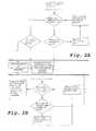
- FIG. 2is a flowchart to depict the system test and the taking over of a new target configuration of the connected devices on the application bus;
- FIGS. 3A and 3Bare block diagrams of the application bus system
- FIG. 4A to 4Cillustrate three configurations of bus subscribers
- FIG. 5is a system consisting of a gateway, bus subscribers and a power module.
- the gatewaydoes not expect a bus subscriber in the initial target configuration, and a configuration mode is started in the gateway for purposes of taking over at least one bus subscriber and for generating a new target configuration with the at least one bus subscriber.
- the switching devicehas at least one control input for querying an upstream switching device as a bus subscriber and/or for querying a gateway ( 20 ), and said switching device also has a control output for selecting a downstream switching device as another bus subscriber.
- an embodiment of the inventionrelates to a system with which actuators as bus subscribers, preferably industrial switching devices such as, for example, power switches or combinations of motor circuit breakers and contactors, are data-technically networked via an application bus system, here preferably via a LIN bus, with the aim of controlling and monitoring the connected industrial switching devices.
- the systemhas at least one gateway that is installed between an open field bus and actuators.
- the single pluggable connection lineconnects the individual bus subscribers or actuators among each other and to the gateway. It serves to transmit data, namely, control and/or status data, and to transmit power to supply the bus subscribers and, if applicable, other components of the system.
- the gatewayis arranged between the open field bus and the connection line, and it has connection devices for connecting with the field bus as well as for connecting the mains voltage and the connection line. Numerous functions that will be elaborated upon below can be carried out via the gateway.
- control wiring to the industrial switching devicesis replaced by a pluggable and easily installed line connection system.
- Complicated and error-prone installations of the control wiringare eliminated and the use of cable conduits needed for laying the lines as well as the installation of the conduits are dispensed with.
- Such wiringcomprises the control lines, here preferably for a contactor, the line for switching the contactor on and off, and the status lines, here, for instance, for querying the switching position of the contactor or the status of a motor circuit breaker (ON/tripped).
- Such devicescan be, for example, industrial switching devices such as power switches, electronic motor-protection relays or frequency converters.
- the system for controlling bus-networked devices with a gateway via an open field buscan have the following features, either individually or in combination with each other.
- a bus controlleris provided here for monitoring the gateway.
- the gatewayitself advantageously has at least one interface to the open field bus, at least one interface to an application bus for controlling and querying at least one actuator or bus subscriber located on the application bus and at least one data output for the communication with at least one bus subscriber. It has also proven to be advantageous for the gateway to have at least one memory unit for permanently storing a bus configuration that can be written by a bus controller and for storing the present bus configuration of the application bus.
- the gatewaycomprises at least a first feed bushing to provide primary supply voltage and at least a second feed bushing to provide auxiliary voltage that can be conducted or that is conducted to the bus subscribers.
- the gatewaycan also be connectable or connected to at least one control line to address the first bus subscriber.
- the gatewayhas also proven to be advantageous for the gateway to have at least one status display to show the operating states of bus subscribers and of the bus communication, and/or the at least one bus subscriber has at least one display to show its own operating status. As a result, it is possible to visually check the proper operation of the system at all times.
- the gatewayadvantageously has at least one actuation element for starting a bus configuration of the bus subscribers connected via the application bus.
- the gatewaychecks via an application bus how many bus subscribers are connected to the application bus, whereby the bus subscribers are advantageously numbered consecutively.
- each bus subscribercan store its specific identification number, and/or the gateway can store the identification numbers in a non-volatile manner.
- this configurationcan be stored or is stored in the gateway ( 20 ) as the target configuration, and control data and/or status data can be exchanged or is exchanged between the gateway and the bus subscribers.
- the at least one bus subscriber or actuatorAs far as the at least one bus subscriber or actuator is concerned, it has proven to be advantageous for it to have at least one control input for querying an upstream bus subscriber and/or the gateway, and it has a control output for selecting a downstream bus subscriber. Moreover, it can encompass at least one control and programming unit for implementing the bus communication and the functionality of the actuator application.
- the at least one bus subscribercan have a device for connection to the mains voltage. Moreover, it advantageously has at least one device to loop through the data stream and/or the auxiliary voltage to a downstream bus subscriber or actuator and/or to relay the auxiliary voltage to an actuator application.
- the at least one bus subscriberhas at least one device to carry out actuator actions and/or at least one device to report actuator actions and/or actuator positions on the application bus, so that communication about the actuator positions and actuator actions is possible via the application bus.
- the at least one bus subscriberadvantageously also has at least one device to write an identification number via the gateway. This makes it possible to check the number of bus subscribers connected to the application bus.
- the bus subscribersare advantageously numbered consecutively.
- Each individual bus subscriberstores the specific identification number in a non-volatile manner, that is to say, the specific identification number is once again available when the system is switched back on after having been switched off and is not lost because the system was switched off. All of the identification numbers are advantageously likewise stored in the gateway in a non-volatile manner.
- the application buscan be a LIN bus with which the control and/or status data and the handling of the configuration of the application bus can be handled or is handled via a protocol which, in particular, consists of LIN data frames with data lengths of 1 to 8 bytes. Fundamentally, a different structure with, for example, other data lengths is also possible.
- a possible application bus configurationcan be permanently written in the gateway. It is likewise possible for the bus controller to overwrite an application bus configuration that has been written.
- At least one actuatorcan be an electric switching device.
- an actuatorcan especially be a combination of motor circuit breakers and contactors.
- a plug-in modulecan have, on the one hand, the actuator properties and, on the one hand, at least one mechanical display to show actuator positions and/or at least one display for its own operating status.
- the actuator positions that can be added to the actuatorsin other words, especially switching devices, can be displayed by the plug-in module.
- a plug-in modulethat can also have appropriate plug-in connectors to connect the connection line.
- the plug-in modulecan have at least one digital input for the connection of a potential-free switching contact. This is also suitable, for instance, for an auxiliary switch to query the position of the motor circuit breaker in a combination of motor circuit breakers and contactors.
- the plug-in modulecan advantageously have at least one circuit interruptor for the actuator.
- a circuit interruptorcan be employed, for example, to electrically lock a reversing starter.
- a plug-in moduleWhen a plug-in module is arranged on a combination of motor circuit breakers and contactors, it can advantageously switch the auxiliary voltage to the contactor coil.
- the above-mentioned other features of such a plug-in modulecan also be advantageously provided, precisely in the case of such a combination of motor circuit breakers and contactors.
- the systemcan also be configured in such a way that a power module is interconnected in the series of bus subscribers or between them, said power module looping through the data stream to the next bus subscriber and/or not looping through the auxiliary voltage.
- the interconnection of a power moduleinterrupts the “linear” power supply from one bus subscriber to another.
- the data connection and the primary voltage between the bus subscriber located upstream from the power module and the bus subscriber located downstream from the power moduleis looped through.
- an external voltage sourceis thus provided that supplies the power module with an auxiliary voltage that is transferred to the next bus subscriber.
- the power moduleadvantageously has at least one display to show the presence of the external auxiliary voltage.
- At least one bus subscriber or actuatorhas a mechanical display to show actuator positions so that these can also be read off without current and problem-free.
- At least one sensorcan be arranged in the series of bus subscribers for purposes of detecting physical quantities.
- a configuration modeadvantageously runs once the actuation element has been actuated.
- FIG. 1Ashows a gateway 20
- FIG. 1Cshows a bus subscriber in the form of a plug-in module 40 on a combination of motor circuit breakers and contactors
- FIG. 1Bshows a power module 50 , also referred to as PM, as typical hardware components of a system by way of an example.
- the gateway 20has an interface to a superordinated control system, for instance, to an open field bus 2 (see FIG. 3A ) such as a Profibus DP, Device Net or CANopen or the like, by means of which it is networked in data-technical terms to the superordinated field bus system.
- the bus subscribers N 1 to Nn that are networked on an application bus 10 and that are used as industrial switching devicesare controlled by the gateway 20 via a flat ribbon cable 8 that is likewise shown in FIG. 3A .
- the gateway 20has a first feed device 24 for the connection of a power supply unit 14 for its own electronics and for the electronics of the bus subscribers, as well as a second feed device 25 for the connection of a power supply unit 16 of the bus subscribers.
- the power supply unit 16is auxiliary voltage for the actuator actions of the bus subscribers, whereby here, for example, the voltage or current is supplied to the combinations of motor circuit breakers and contactors.
- the gateway 20has at least one light-emitting diode 28 that serves to display the status of operating states of the gateway and of the bus communication.
- the gateway 20also has a configuration button 27 that serves to start the automatic bus configuration of the bus subscribers; in the gateway 20 , there is at least one memory module that is employed to permanently store the bus configuration.
- the plug-in module 40 shown in FIG. 1Cwhich is also referred to as SM, is used for a combination of motor circuit breakers and contactors, said module being mechanically and electrically adapted to the contactor.
- the plug-in module 40has two pin contacts 49 that serve to establish the electric connection to a contactor coil. This plug-in module takes over the control wiring. This is how the contactor coil is electrically actuated and the contactor switching position is electrically queried. There is also the possibility to query an electrically potential-free contact insofar as or to the extent that such a contact is present.
- the plug-in module 40also has a switching position display 46 that mechanically—visible to the operator—displays the switching position.
- the plug-in module 40also comprises the following features:
- Such a circuit interruptor 45 for the actuatorcan be used, for example, to electrically lock a reversing starter.
- the application bus 10is operated by means of the above-mentioned multiwire flat ribbon cable 8 —six-wire in this case (see FIGS. 3A and 3B ).
- the line 8extends or is laid from one bus subscriber to the next via connection plugs.
- the plug-in module 40For each bus subscriber Nx, there are two sockets 41 , 42 in the plug-in module 40 that serve to plug in the flat ribbon cable 8 on the bus input side and on the bus output side. Due to the linear arrangement of the subscribers, the last bus subscriber Nn does not have a plugged-in flat ribbon cable 8 on the output side as a connection line; the output side (socket 42 ) of the bus subscriber remains “empty”.
- Each bus subscriberhas a status display 28 , 48 , 58 that serves to display the device status, preferably visually as an LED.
- the plug-in module 40 and the power module 50 of each bus subscriber Nxhas a two-pole terminal 44 , 45 , 54 , 55 to which a potential-free contact can be connected, for instance, for an auxiliary switch in order to query the position of the motor circuit breaker.
- FIG. 5shows additional details of the system.
- Three lines L 1 , L 2 , L 3 of the mains connection and the load Mare shown on the first bus subscriber N 1 , which is configured here by way of an example as a combination of motor circuit breakers and contactors.
- a motor circuit breakeris shown in the upper half of the bus subscribers designated here as N 1 , N 2 , N 3 to Nn, while the plug-in module 40 with its sockets 41 , 42 and 43 plugged onto a contactor and the mechanical display 48 for the contact position of the contactor are shown in the lower half.
- the depiction according to FIG. 5can be understood as an application bus 10 having n subscribers into which the power module 50 shown in FIG. 5 can optionally be inserted. A more detailed explanation of the power module 50 will follow below.
- FIG. 2Ashows a flowchart depicting a system test
- FIG. 2Bshows a flowchart for taking over a new target configuration. The flowcharts of the two figures make a transition to each other.
- the gatewaychecks whether a subscriber can be reached on the bus. If this question is answered with “yes”, it is subsequently queried whether the subscriber is expected at the gateway. If this question can likewise be answered with “yes”, the subscriber is configured by the gateway in a subsequent step. Then the gateway selects the next subscriber via the configured subscriber. Subsequently, the gateway once again checks whether a subscriber can be reached on the bus and the query loop is thus closed. If this question is answered with “no” already at the beginning or at this point in time, the next question is asked as to whether a subscriber is expected by the gateway.
- the actual configurationis the same as the target configuration and the actual configuration is not the same as the target configuration.
- the systemis ready for operation and the status is shown with the continuous lit status LED 28 ′′.
- the status LED 28 ′′blinks, as a result of which the operator is prompted to actuate the configuration button 27 .
- the present configurationis taken over as the target configuration and the system goes on to the final checking ( FIG. 2B ).
- each individual subscriberis queried by the gateway and the parameters that might be present in the gateway are stored.
- a checkis also carried out as to whether the maximum permissible number of subscribers on the application bus has not been exceeded. Should this be the case, the gateway once again goes into error status since the target configuration is not the same as the actual configuration. If this is not the case, the subscriber data is read out and stored in the gateway. Via the subscribers that have been reached, the gateway selects the next subscriber and checks for this one as well whether it can be reached. Once all of the subscribers have been detected, the gateway and the subscribers go into the normal operating state in which the control data or status data is exchanged between the gateway and the subscribers. This configuration is permanently stored in the gateway as the new target configuration.
- the power module (PM) 50can optionally be interconnected in the linear series of subscribers ( FIG. 3B ). This is also schematically shown again in FIG. 5 .
- the interconnection of a power moduleinterrupts the “linear” power supply from one subscriber to the next.
- the data connection and the primary voltage 14 between the bus subscribers N 1 , N 2 , N 3 located upstream from the power module and the bus subscriber Nn located downstream from the power moduleis looped through.
- the power module PM 50installed in the bus multiconductor, a new feed is implemented for the subsequent bus subscribers (group G) in the bus series; for this purpose, the power module is connected to a power supply unit 16 ′, for instance, 24 volt DC.
- the drawing in FIG. 3Bshows the power supply unit 16 ′ coming from below (relative to the drawing page) and, in FIG. 5 , coming from above (relative to the drawing page).
- This power supply unitcan be, for instance, a contactor supply for a group of bus subscribers that are supposed to function as their own emergency-OFF group.
- the power modulehas screwed terminals or sockets 54 , 55 for the power feed 16 ′.
- the power modulelike the other bus subscribers—has two sockets 51 , 52 , one of which being the input and the other being the output for the connection plug system.
- the power moduleis provided with a status display 58 , especially for visual display via an LED showing whether the feed voltage 16 ′ is being applied to the group G of the bus subscribers that are downstream from the power module.
- connection line 8transfers control data or status data on the one hand, and the requisite power for the switching devices on the other hand.
- the use of the above-mentioned power modulesmakes it possible to form groups of bus subscribers, as a result of which a separate power supply and power monitoring of such a group can be achieved.
- the group formationcan be utilized, for example, to set up a certain segment or a certain circuit in which the switching devices form a separate emergency-OFF group, in that these can be monitored and connected or disconnected.
- the power modulescan be optionally employed.
- FIGS. 4A to 4CThe function and mode of operation of the system are depicted on the basis of FIGS. 4A to 4C .
- a while circle with the designation 28 ′′ and 48 ′′is a lit LED, while a black circle without any further designation is an unlit LED 28 , 48 , and a circle with rays around it with the designation 28 ′ and 48 ′ is a blinking LED.
- the gateway 20is the central element for the connection to the system of the open field bus 2 .
- the bus subscribers N 1 to Nxare supplied with power, controlled and monitored by the gateway, which also transmits control and status data of all connected bus subscribers to the superordinated field bus 2 .
- the gatewayis firstly connected to the power supply unit 14 for its own electronics and secondly to the power supply unit 16 , which supplies the bus subscribers.
- the auxiliary voltage 16 for bus subscribersfor instance, voltage to the contactor coils
- can be switched off independently of the bus functionalitye.g. emergency-OFF system.
- the bus subscriberssuch as, for instance, combinations of motor circuit breakers and contactors, can be connected to plug-in modules consecutively. If the primary voltage 14 is being switched on for the first time after the system has been set up, then the gateway 20 checks the connected bus subscribers N 1 to Nx on the application bus system, as already explained above in conjunction with FIGS. 2A and 2B . In the initial situation, an arrangement without bus subscribers is provided as the target configuration. This situation is then updated after the individual bus subscribers have been integrated, as already described above.
- n bus subscribersare wired in an initial target configuration, that is to say, without bus subscribers.
- the gateway 20at first expects no bus subscribers on the basis of the target configuration. This is why, due to the configuration error, the gateway goes into error status and this is visually displayed on the gateway 20 by a blinking LED 28 ′ (top right in the corner of the gateway 20 shown in FIG. 4A ).
- the control LED on the first bus subscriber N 1which is directly connected to the gateway via the connection line 8 , is likewise blinking (LED 48 ′) since this was not expected by the gateway. All of the other status or control LEDs 48 of the other bus subscribers N 2 to Nx are not lit, in other words, they are switched off.
- the configuration button 27is pushed in order to take over the connected bus subscribers at the gateway 20 as the target configuration.
- the gatewayconsecutively checks how many bus subscribers (N 1 to Nx) are connected to the application bus 10 .
- the bus subscribersare numbered consecutively.
- Each individual bus subscriberstores the specific identification number in a non-volatile manner, that is to say, the specific identification number is once again available when the system is switched on again after having been switched off and this number is not lost as a result of the system having been switched off. All identification numbers are likewise stored in a non-volatile manner in the gateway. After this procedure, all of the connected bus subscribers are configured.
- the LED 28 ′′ on the gateway and the LEDs 48 ′′ on the bus subscribersare all statically switched on and lit.
- FIG. 4Balso depicts the situation in which, upstream from the gateway, the system is electrically switched off and once again switched on in terms of the primary voltage 14 .
- the gatewaychecks all of the connected bus subscribers consecutively and compares them one step at a time with the internally stored target configuration. In the described situation, the target situation matches the connected subscriber configuration (actual situation), since it is unchanged. Thus the system remains ready for operation.
- the individual bus subscriberscan now be actuated and monitored by means of the bus controller of the superordinated open field bus 2 . If the structure of the connected devices changes, for example, if devices are expanded or removed, this is detected by the gateway on the basis of the diverging target-actual configuration and indicated by the status LED 28 .
- FIG. 4Cshows an example of an existing configuration of a gateway 20 and n bus subscribers N 1 to Nx that is ready for operation after having been configured. If this structure is augmented by one or more bus subscribers (Nin), this results in the following scenario after the system is switched on: the gateway status LED 28 ′ is blinking because the previous target configuration (n bus subscribers) deviates from the actual configuration (n+1 bus subscribers). Moreover, the LED 48 ′ of the first added (also in case of several added) bus subscribers Nin is also blinking because this or these bus subscriber(s) was/were not expected by the gateway. In this manner, the user can very easily recognize on the basis of the blinking LEDs where the deviation of the actual configuration is present. By simply pushing the configuration button 27 , the new configuration is automatically taken over by the gateway. After the automatic bus configuration has run, one would have now the same situation for n+x bus subscribers as was shown in FIG. 4B for n subscribers.
- FIG. 5shows the use of at least one power module 50 to form a group G of bus subscribers.
- the bus subscribershere the plug-in module on the combination of motor circuit breakers and contactors—located downstream from the power module are cut off from the auxiliary power supply unit 16 for the subscriber application, this is done by the power module, and auxiliary voltage 16 ′ is newly fed to the subscriber application.
- the application bus 10is looped through data-technically and in terms of the primary power supply unit 14 for the electronics of the bus subscriber at a ratio of 1:1 in the power module.
- the auxiliary voltage 16 ′ fed into the power moduleis switched off, the bus subscribers, for instance, contactors, are current-free downstream from the power module.
- the electronics of the bus subscriberscontinue to be supplied with power and therefore continue to transmit to the gateway the current actuator status, for instance, contact status of the motor starter.
- the use of the power moduleshas an advantageous effect in that independent groups of combinations of motor circuit breakers and contactors can be formed, e.g. an emergency-OFF switching circuit that can be separately switched off.
- the use of power modulescan take place at any desired place in the connection plug system.
- Several power modulescan also be built into the connection plug system, so that several independent groups of bus subscribers are formed.
Landscapes
- Engineering & Computer Science (AREA)
- Theoretical Computer Science (AREA)
- General Engineering & Computer Science (AREA)
- Physics & Mathematics (AREA)
- General Physics & Mathematics (AREA)
- Computer Hardware Design (AREA)
- Computer Networks & Wireless Communication (AREA)
- Signal Processing (AREA)
- Mathematical Physics (AREA)
- Small-Scale Networks (AREA)
- Remote Monitoring And Control Of Power-Distribution Networks (AREA)
Abstract
Description
- 2 open field bus
- 8 connection line (for example, 6-wire flat ribbon line)
- 10 application bus (LIN bus)
- N1 to Nn-x bus subscribers (actuator, motor starter, power switch
- 14,14′ primary voltage (24 volt DC)
- 16,16′ auxiliary voltage (24 volt DC)
- 20 gateway
- 22 socket of the gateway
- 23 sockets for the open field bus
- 24 primary voltage feed (screw-in terminals)
- 25 auxiliary voltage feed (screw-in terminals)
- 27 configuration button
- 28 status LED
- 40 SM plug-in module
- 41,42 socket for connection plug on flat ribbon cable
- 44,45 socket for power supply unit
- 46 mechanical display
- 48 control LED
- 49 pins for arrangement on contactor in a motor starter
- 50 power module PM
- 51,52 sockets for connection plugs on flat ribbon cable
- 54,55 socket for power supply unit
- 58 control LED
- L1, L2, L3 mains connection for bus subscribers (actuator)
- M load (motor) on main voltage
Claims (35)
Applications Claiming Priority (1)
| Application Number | Priority Date | Filing Date | Title |
|---|---|---|---|
| PCT/EP2007/006017WO2009006916A1 (en) | 2007-07-06 | 2007-07-06 | System and method for controlling bus-networked devices via an open field bus |
Related Parent Applications (1)
| Application Number | Title | Priority Date | Filing Date |
|---|---|---|---|
| PCT/EP2007/006017A-371-Of-InternationalWO2009006916A1 (en) | 2007-07-06 | 2007-07-06 | System and method for controlling bus-networked devices via an open field bus |
Related Child Applications (1)
| Application Number | Title | Priority Date | Filing Date |
|---|---|---|---|
| US14/555,607ContinuationUS9164934B2 (en) | 2007-07-06 | 2014-11-27 | System and method for controlling bus-networked devices via an open field bus |
Publications (2)
| Publication Number | Publication Date |
|---|---|
| US20110119507A1 US20110119507A1 (en) | 2011-05-19 |
| US8935435B2true US8935435B2 (en) | 2015-01-13 |
Family
ID=39205117
Family Applications (4)
| Application Number | Title | Priority Date | Filing Date |
|---|---|---|---|
| US12/665,438Active2031-02-28US8935435B2 (en) | 2007-07-06 | 2007-07-06 | System and method for controlling bus-networked devices via an open field bus |
| US14/555,607ActiveUS9164934B2 (en) | 2007-07-06 | 2014-11-27 | System and method for controlling bus-networked devices via an open field bus |
| US14/819,458Active2028-07-19US10599604B2 (en) | 2007-07-06 | 2015-08-06 | System and method for controlling bus-networked devices via an open field bus |
| US16/788,327ActiveUS11182327B2 (en) | 2007-07-06 | 2020-02-12 | System and method for controlling bus-networked devices via an open field bus |
Family Applications After (3)
| Application Number | Title | Priority Date | Filing Date |
|---|---|---|---|
| US14/555,607ActiveUS9164934B2 (en) | 2007-07-06 | 2014-11-27 | System and method for controlling bus-networked devices via an open field bus |
| US14/819,458Active2028-07-19US10599604B2 (en) | 2007-07-06 | 2015-08-06 | System and method for controlling bus-networked devices via an open field bus |
| US16/788,327ActiveUS11182327B2 (en) | 2007-07-06 | 2020-02-12 | System and method for controlling bus-networked devices via an open field bus |
Country Status (6)
| Country | Link |
|---|---|
| US (4) | US8935435B2 (en) |
| EP (1) | EP2165472A1 (en) |
| JP (1) | JP5431314B2 (en) |
| CN (1) | CN101690019B (en) |
| CA (1) | CA2691731C (en) |
| WO (1) | WO2009006916A1 (en) |
Cited By (6)
| Publication number | Priority date | Publication date | Assignee | Title |
|---|---|---|---|---|
| US20130275784A1 (en)* | 2010-10-27 | 2013-10-17 | Volkswagen Ag | Network and method for operating a network |
| US9725078B2 (en)* | 2011-12-19 | 2017-08-08 | Goldhofer Aktiengesellschaft | Cabling device and electronic brake system for a modular heavy goods vehicle and for a heavy goods vehicle |
| EP3206106A1 (en)* | 2016-02-09 | 2017-08-16 | Nxp B.V. | Power-domain assignment |
| US11183800B2 (en) | 2018-08-29 | 2021-11-23 | Leviton Manufacturing Co., Inc. | Pin and sleeve device with indication |
| US11411767B2 (en) | 2017-05-24 | 2022-08-09 | Wago Verwaltungsgesellschaft Mbh | Module unit for connecting a data bus subscriber |
| US11682889B2 (en) | 2019-01-07 | 2023-06-20 | Leviton Manufacturing Co., Inc. | Electrical device with built-in sensors and/or communications |
Families Citing this family (23)
| Publication number | Priority date | Publication date | Assignee | Title |
|---|---|---|---|---|
| US8935435B2 (en)* | 2007-07-06 | 2015-01-13 | Eaton Electrical Ip Gmbh & Co. Kg | System and method for controlling bus-networked devices via an open field bus |
| US8904074B2 (en)* | 2007-12-31 | 2014-12-02 | Schneider Electric USA, Inc. | Method and apparatus for distributing configuration files in a distributed control system |
| JP5875098B2 (en) | 2011-06-30 | 2016-03-02 | 矢崎総業株式会社 | Wire harness structure and electronic device control system |
| FR2996938B1 (en)* | 2012-10-17 | 2015-11-13 | Eurocopter France | ARCHITECTURE FOR COMMUNICATING AND DISTRIBUTING ELECTRICAL POWER OF AN AIRCRAFT, AND AIRCRAFT |
| US10058031B1 (en) | 2015-02-28 | 2018-08-28 | Hydro-Gear Limited Partnership | Lawn tractor with electronic drive and control system |
| US9980434B1 (en) | 2015-02-28 | 2018-05-29 | Hydro-Gear Limited Partnership | Network for placing a plurality of lawnmower components in operative communication |
| US10409274B1 (en) | 2016-07-06 | 2019-09-10 | National Technology & Engineering Solutions Of Sandia, Llc | Control system backplane monitoring with FPGA |
| FR3053828B1 (en)* | 2016-07-08 | 2019-10-25 | Schneider Electric Industries Sas | INTERCONNECTION MODULE OF A CIRCUIT BREAKER AND A CONTACTOR FOR AN ELECTRICAL ASSEMBLY |
| DE102016223795A1 (en) | 2016-11-30 | 2018-05-30 | Siemens Aktiengesellschaft | Command and message system for automation technology |
| DE102017206769B4 (en) | 2017-04-21 | 2024-12-24 | Festo Se & Co. Kg | gateway module and module arrangement |
| DE102017109862B4 (en)* | 2017-05-08 | 2023-09-07 | Webasto SE | Programmable plug |
| DE102017208836A1 (en) | 2017-05-24 | 2018-11-29 | Wago Verwaltungsgesellschaft Mbh | Status signal output |
| WO2019124275A1 (en)* | 2017-12-21 | 2019-06-27 | 村田機械株式会社 | Method for controlling communication system, communication system, and relay device |
| JP6856048B2 (en)* | 2018-04-03 | 2021-04-07 | オムロン株式会社 | Control system and control method |
| JP2020025397A (en)* | 2018-08-07 | 2020-02-13 | オムロン株式会社 | State acquisition method for power unit, and state acquisition device for power unit |
| CN108984458B (en)* | 2018-08-09 | 2021-10-29 | 哈尔滨诺信工大测控技术有限公司 | Self-defined serial open type bus |
| DE102018133657A1 (en) | 2018-12-28 | 2020-07-02 | Beckhoff Automation Gmbh | BASIC MODULE AND FUNCTIONAL MODULE FOR A CONTROL CABINET SYSTEM AND CONTROL CABINET SYSTEM |
| DE102018133647A1 (en) | 2018-12-28 | 2020-07-02 | Beckhoff Automation Gmbh | Control cabinet system consisting of basic module and function modules as well as function module |
| DE102018133646A1 (en) | 2018-12-28 | 2020-07-02 | Beckhoff Automation Gmbh | Basic module and function module for a control cabinet system |
| EP3700138B1 (en)* | 2019-02-22 | 2023-08-02 | Volvo Car Corporation | Monitoring lin nodes |
| DE102019106082B4 (en) | 2019-03-11 | 2021-06-24 | Beckhoff Automation Gmbh | CABINET SYSTEM WITH SEAL INSERT |
| US11589195B2 (en) | 2020-08-20 | 2023-02-21 | Ip Co, Llc | Asset tracking systems and methods |
| CN118400221B (en)* | 2024-05-30 | 2024-10-15 | 中国矿业大学 | Low-delay LIN bus control circuit and control method |
Citations (69)
| Publication number | Priority date | Publication date | Assignee | Title |
|---|---|---|---|---|
| DE3424866A1 (en) | 1984-07-06 | 1986-01-16 | Messerschmitt-Bölkow-Blohm GmbH, 8012 Ottobrunn | METHOD AND ARRANGEMENT FOR TRANSMITTING DATA, IN PARTICULAR IN AN AIRPLANE |
| EP0393293A1 (en) | 1989-04-21 | 1990-10-24 | International Business Machines Corporation | Method and apparatus for cyclic reservation multiple access in a communications system |
| DE3915456A1 (en) | 1989-05-11 | 1990-11-15 | Herion Werke Kg | Two wire system for selective grouped load control - has microprocessor for digitised control of senser and receiver modules operating on multi-bit signals for enhanced reliability |
| SU1732366A1 (en) | 1990-07-02 | 1992-05-07 | Научно-производственное объединение "Дальняя связь" | Device for telemetry and supervisory indication |
| PL159060B1 (en) | 1989-01-09 | 1992-11-30 | Method for the remote control of the energy switch in dangerous mine areas and a system for the remote control of the energy switch in dangerous mine areas | |
| PL295090A2 (en) | 1992-06-29 | 1993-04-05 | B P Kolejowych | Method of automatically controlling operation of a railway contact system in particular individual substations belonging to that system |
| EP0637784A1 (en) | 1993-08-05 | 1995-02-08 | Siemens Aktiengesellschaft | Module with bus connector |
| US5422808A (en)* | 1993-04-20 | 1995-06-06 | Anthony T. Catanese, Jr. | Method and apparatus for fail-safe control of at least one electro-mechanical or electro-hydraulic component |
| RU2037190C1 (en) | 1991-04-03 | 1995-06-09 | Институт кибернетики им.В.М.Глушкова АН Украины | Multichannel system for recording physical quantities |
| EP0779640A2 (en) | 1995-12-12 | 1997-06-18 | Moeller GmbH | Amplifier module with bus interface, for control arrangement of switching devices |
| EP0788043A2 (en) | 1996-01-30 | 1997-08-06 | Weidmüller Interface GmbH & Co. | Method and fieldbus system for serial data transmission in object oriented applications |
| DE19606747A1 (en) | 1996-02-23 | 1997-08-28 | Scharco Elektronik Gmbh & Co K | Display and position equipment industrial controller e.g. for compressor |
| DE19756918A1 (en) | 1997-06-25 | 1999-01-07 | Mitsubishi Electric Corp | Communications control unit especially for master-slave network |
| US5978593A (en)* | 1996-09-05 | 1999-11-02 | Ge Fanuc Automation North America, Inc. | Programmable logic controller computer system with micro field processor and programmable bus interface unit |
| US6095867A (en)* | 1998-09-21 | 2000-08-01 | Rockwell Technologies, Llc | Method and apparatus for transmitting power and data signals via a network connector system including integral power capacitors |
| JP2000267982A (en) | 1999-03-16 | 2000-09-29 | Fuji Xerox Co Ltd | Information processor |
| PL180146B1 (en) | 1996-02-05 | 2000-12-29 | Daimlerchrysler Rail Systems S | Power supply system for railway traffic control devices, especially computer devices |
| DE19931999A1 (en) | 1999-07-09 | 2001-01-18 | Leuze Electronic Gmbh & Co | BCL addressing |
| DE19935192A1 (en) | 1999-07-27 | 2001-02-22 | Moeller Gmbh | Addressing participants in a bus system |
| US6256544B1 (en)* | 1996-08-13 | 2001-07-03 | Duerr Systems Gmbh | Apparatus and method for controlling functional units in a manufacturing installation |
| JP2002077214A (en) | 2000-08-24 | 2002-03-15 | Mitsubishi Electric Corp | Multiplex transmission equipment for mobile |
| US20020042857A1 (en)* | 2000-10-05 | 2002-04-11 | Jones Nicolas D.L. | Industrial multi-port data connector system |
| GB2372872A (en) | 2001-03-03 | 2002-09-04 | John Eric Dowell | Computer hard drive rack |
| US6522515B1 (en)* | 1999-01-08 | 2003-02-18 | Littelfuse, Inc. | Data and power connector port |
| DE10147446A1 (en) | 2001-09-26 | 2003-04-17 | Bosch Gmbh Robert | Method and device for monitoring a bus system and bus system |
| DE10147442A1 (en) | 2001-09-26 | 2003-04-17 | Bosch Gmbh Robert | Method and device and control unit for monitoring a bus system |
| EP1315355A2 (en) | 2001-11-27 | 2003-05-28 | Eaton Corporation | Translator apparatus for two communication networks |
| US20030099229A1 (en) | 2000-02-18 | 2003-05-29 | Albert Tretter | Electrical device |
| JP2003218904A (en) | 2002-01-24 | 2003-07-31 | Auto Network Gijutsu Kenkyusho:Kk | In-vehicle communication system |
| RU2214000C2 (en) | 1999-08-27 | 2003-10-10 | Джоб Лиценз Гмбх & Ко. Кг | Method and device for automatic assignment of alarm addresses in emergency warning units |
| US6640140B1 (en)* | 2000-10-10 | 2003-10-28 | Schneider Automation Inc. | PLC executive with integrated web server |
| JP2004088208A (en) | 2002-08-23 | 2004-03-18 | Sony Corp | Data transmission system and method therefor |
| US20040059844A1 (en)* | 2002-09-20 | 2004-03-25 | Woodhead Industries, Inc. | Network active I/O module with removable memory unit |
| WO2004028083A1 (en) | 2002-09-23 | 2004-04-01 | Huawei Technologies Co., Ltd. | A scheduling method for polling device data |
| US20040160990A1 (en)* | 2002-09-25 | 2004-08-19 | Oleg Logvinov | Method and system for timing controlled signal transmission in a point to multipoint power line communications system |
| WO2005001699A2 (en) | 2003-06-26 | 2005-01-06 | Endress + Hauser Process Solutions Ag | Field bus distribution unit |
| RU43709U1 (en) | 2004-09-24 | 2005-01-27 | Кучерявый Андрей Евгеньевич | INSTITUTIONAL AUTOMATIC TELEPHONE STATION ON THE BASIS OF A COMMUTATION SYSTEM WITH PACKAGE SWITCHING |
| US6881903B2 (en)* | 2001-04-20 | 2005-04-19 | Siemens Aktiengesellschaft | Multi conductor arrangement for transferring energy and/or data |
| DE10358231A1 (en) | 2003-12-12 | 2005-07-07 | Abb Patent Gmbh | Device for connecting field appliances via bus system to supervisory control system e.g. for supervisory control system, has field bus connection module with bus circuit for connection to supervisory system |
| US20050201306A1 (en) | 2004-03-15 | 2005-09-15 | Engel Glenn R. | Method and system for supplying power to multiple devices using power-transmitting network connections |
| US6970772B2 (en)* | 2002-04-15 | 2005-11-29 | Wabco Gmbh & Co. Ohg | Method and system for exchanging data in a vehicle train via a PLC data bus |
| EP1618943A1 (en) | 2004-07-20 | 2006-01-25 | Esa Electronic Engineering S.r.L. | Valve control system for dust collector units |
| US20060058847A1 (en) | 2004-08-31 | 2006-03-16 | Watlow Electric Manufacturing Company | Distributed diagnostic operations system |
| JP2006511172A (en) | 2002-12-20 | 2006-03-30 | ダイムラークライスラー・アクチェンゲゼルシャフト | Automatic address assignment method in bus system |
| US20060067209A1 (en) | 2004-07-29 | 2006-03-30 | Modius, Inc. | Universal configurable device gateway |
| US20060077917A1 (en) | 2004-10-07 | 2006-04-13 | Honeywell International Inc. | Architecture and method for enabling use of wireless devices in industrial control |
| US7046166B2 (en)* | 2003-04-29 | 2006-05-16 | Rockwell Scientific Licensing, Llc | Modular wireless integrated network sensor (WINS) node with a dual bus architecture |
| CN1780247A (en) | 2004-11-26 | 2006-05-31 | 浙江中科正方电子技术有限公司 | Vehicle body CAN bus controlling system |
| US7072407B2 (en)* | 2000-01-31 | 2006-07-04 | Brookline Flolmstead Llc | Combination power and full duplex data cable |
| US7075414B2 (en)* | 2003-05-13 | 2006-07-11 | Current Technologies, Llc | Device and method for communicating data signals through multiple power line conductors |
| US7093050B2 (en)* | 2000-12-29 | 2006-08-15 | Empir Ab | Control arrangement |
| US20060259204A1 (en) | 2005-05-10 | 2006-11-16 | Jordan Patrick D | Vehicle network with time slotted access and method |
| DE102005024559A1 (en) | 2005-05-28 | 2006-11-30 | Daimlerchrysler Ag | Sensors/actuators-databus e.g. CAN, messages assignment method for airplane, involves assigning sensor recognition and mathematical value or other recognition/value during assignment, and sending transmission function between two databuses |
| JP2007174418A (en) | 2005-12-22 | 2007-07-05 | Matsushita Electric Works Ltd | Wiring system |
| US20070198748A1 (en)* | 2006-02-01 | 2007-08-23 | Leviton Manufacturing Co., Inc. | Power line communication hub system and method |
| US7327222B2 (en)* | 2001-11-29 | 2008-02-05 | Nokia Corporation | Transmission system for transmitting data via current conducting branches |
| US20080177919A1 (en)* | 2006-09-07 | 2008-07-24 | Denso Corporation | Communication system and method for assigning addresses |
| RU2332803C2 (en) | 2005-11-17 | 2008-08-27 | Общество с ограниченной ответственностью "ХитТелеком" | Communication system |
| US7602617B2 (en)* | 2005-09-30 | 2009-10-13 | Rockwell Automation Technologies, Inc. | On-machine backplane mounted modular power and data distribution system |
| US7715176B2 (en)* | 2007-05-16 | 2010-05-11 | Perez Marcelo A | Modular power monitoring system |
| US7741958B2 (en)* | 2003-09-15 | 2010-06-22 | Rockwell Automation Technologies, Inc. | Network cable for transmitting data and power to networked devices |
| US7804427B1 (en)* | 2009-03-20 | 2010-09-28 | Honda Motor Co., Ltd. | Device and method for automatic reset of encoder |
| US7923855B2 (en)* | 2006-02-17 | 2011-04-12 | Calix, Inc. | Communication between network interface device and subscriber devices via power supply lines |
| US7945340B2 (en)* | 2005-03-14 | 2011-05-17 | Omron Corporation | Programmable controller system |
| US20110119507A1 (en)* | 2007-07-06 | 2011-05-19 | Eaton Industries Gmbh | System and method for controlling bus-networked devices via an open field bus |
| JP2011122701A (en) | 2009-12-14 | 2011-06-23 | Autonetworks Technologies Ltd | Electronic control unit, manufacturing method of automatic transmission including the electronic unit, and connector fixture used in the manufacturing method |
| US8004112B2 (en)* | 2005-09-15 | 2011-08-23 | Panasonic Corporation | Communication apparatus, communication system, image capture apparatus, video capture apparatus, and setting method thereof |
| US20110260556A1 (en)* | 2008-09-30 | 2011-10-27 | Tectonica Australia Pty Ltd. | Personal portable power distribution apparatus |
| US8149587B2 (en)* | 2007-11-13 | 2012-04-03 | Rockwell Automation Technologies, Inc. | Drive modularity |
Family Cites Families (9)
| Publication number | Priority date | Publication date | Assignee | Title |
|---|---|---|---|---|
| EP0788627B1 (en)* | 1994-10-24 | 1999-12-15 | Fisher-Rosemount Systems, Inc. | Apparatus for providing access to field devices in a distributed control system |
| US6377859B1 (en)* | 1996-10-04 | 2002-04-23 | Fisher Controls International, Inc. | Maintenance interface device for a use in a process control network |
| US6999824B2 (en)* | 1997-08-21 | 2006-02-14 | Fieldbus Foundation | System and method for implementing safety instrumented systems in a fieldbus architecture |
| US6249913B1 (en)* | 1998-10-09 | 2001-06-19 | General Dynamics Ots (Aerospace), Inc. | Aircraft data management system |
| US7590140B2 (en)* | 2004-06-08 | 2009-09-15 | Elmos Semiconductor Ag | Method for addressing the participants of a bus system |
| CN1595757A (en)* | 2004-07-06 | 2005-03-16 | 周强 | Method for optimizing power load of power consuming enterprise |
| US7489977B2 (en)* | 2005-12-20 | 2009-02-10 | Fieldbus Foundation | System and method for implementing time synchronization monitoring and detection in a safety instrumented system |
| DE102006030706B4 (en) | 2006-06-30 | 2014-01-23 | Eaton Industries Gmbh | System and method for controlling bus-networked devices via an open fieldbus |
| US20140293849A1 (en)* | 2013-03-29 | 2014-10-02 | Hewlett-Packard Development Company, L.P. | Powering a network device with converted electrical power |
- 2007
- 2007-07-06USUS12/665,438patent/US8935435B2/enactiveActive
- 2007-07-06WOPCT/EP2007/006017patent/WO2009006916A1/enactiveApplication Filing
- 2007-07-06JPJP2010513666Apatent/JP5431314B2/enactiveActive
- 2007-07-06CACA2691731Apatent/CA2691731C/enactiveActive
- 2007-07-06CNCN200780053681.6Apatent/CN101690019B/enactiveActive
- 2007-07-06EPEP07785923Apatent/EP2165472A1/ennot_activeCeased
- 2014
- 2014-11-27USUS14/555,607patent/US9164934B2/enactiveActive
- 2015
- 2015-08-06USUS14/819,458patent/US10599604B2/enactiveActive
- 2020
- 2020-02-12USUS16/788,327patent/US11182327B2/enactiveActive
Patent Citations (83)
| Publication number | Priority date | Publication date | Assignee | Title |
|---|---|---|---|---|
| US4763320A (en) | 1984-07-06 | 1988-08-09 | Messerschmitt-Bolkow-Blohm Gmbh | Method and arrangement for transmitting data, especially in an aircraft |
| DE3424866A1 (en) | 1984-07-06 | 1986-01-16 | Messerschmitt-Bölkow-Blohm GmbH, 8012 Ottobrunn | METHOD AND ARRANGEMENT FOR TRANSMITTING DATA, IN PARTICULAR IN AN AIRPLANE |
| PL159060B1 (en) | 1989-01-09 | 1992-11-30 | Method for the remote control of the energy switch in dangerous mine areas and a system for the remote control of the energy switch in dangerous mine areas | |
| EP0393293A1 (en) | 1989-04-21 | 1990-10-24 | International Business Machines Corporation | Method and apparatus for cyclic reservation multiple access in a communications system |
| DE68920028T2 (en) | 1989-04-21 | 1995-07-06 | Ibm | Method and device for multiple access with cyclical reservation in a communication system. |
| DE3915456A1 (en) | 1989-05-11 | 1990-11-15 | Herion Werke Kg | Two wire system for selective grouped load control - has microprocessor for digitised control of senser and receiver modules operating on multi-bit signals for enhanced reliability |
| SU1732366A1 (en) | 1990-07-02 | 1992-05-07 | Научно-производственное объединение "Дальняя связь" | Device for telemetry and supervisory indication |
| RU2037190C1 (en) | 1991-04-03 | 1995-06-09 | Институт кибернетики им.В.М.Глушкова АН Украины | Multichannel system for recording physical quantities |
| PL295090A2 (en) | 1992-06-29 | 1993-04-05 | B P Kolejowych | Method of automatically controlling operation of a railway contact system in particular individual substations belonging to that system |
| US5422808A (en)* | 1993-04-20 | 1995-06-06 | Anthony T. Catanese, Jr. | Method and apparatus for fail-safe control of at least one electro-mechanical or electro-hydraulic component |
| EP0637784A1 (en) | 1993-08-05 | 1995-02-08 | Siemens Aktiengesellschaft | Module with bus connector |
| EP0779640A2 (en) | 1995-12-12 | 1997-06-18 | Moeller GmbH | Amplifier module with bus interface, for control arrangement of switching devices |
| EP0788043A2 (en) | 1996-01-30 | 1997-08-06 | Weidmüller Interface GmbH & Co. | Method and fieldbus system for serial data transmission in object oriented applications |
| PL180146B1 (en) | 1996-02-05 | 2000-12-29 | Daimlerchrysler Rail Systems S | Power supply system for railway traffic control devices, especially computer devices |
| DE19606747A1 (en) | 1996-02-23 | 1997-08-28 | Scharco Elektronik Gmbh & Co K | Display and position equipment industrial controller e.g. for compressor |
| US6256544B1 (en)* | 1996-08-13 | 2001-07-03 | Duerr Systems Gmbh | Apparatus and method for controlling functional units in a manufacturing installation |
| US5978593A (en)* | 1996-09-05 | 1999-11-02 | Ge Fanuc Automation North America, Inc. | Programmable logic controller computer system with micro field processor and programmable bus interface unit |
| US6430218B1 (en) | 1997-06-25 | 2002-08-06 | Mitsubishi Denki Kabushiki Kaisha | Communication control apparatus |
| DE19756918A1 (en) | 1997-06-25 | 1999-01-07 | Mitsubishi Electric Corp | Communications control unit especially for master-slave network |
| US6095867A (en)* | 1998-09-21 | 2000-08-01 | Rockwell Technologies, Llc | Method and apparatus for transmitting power and data signals via a network connector system including integral power capacitors |
| US6522515B1 (en)* | 1999-01-08 | 2003-02-18 | Littelfuse, Inc. | Data and power connector port |
| JP2000267982A (en) | 1999-03-16 | 2000-09-29 | Fuji Xerox Co Ltd | Information processor |
| DE19931999A1 (en) | 1999-07-09 | 2001-01-18 | Leuze Electronic Gmbh & Co | BCL addressing |
| DE19935192A1 (en) | 1999-07-27 | 2001-02-22 | Moeller Gmbh | Addressing participants in a bus system |
| US6838999B1 (en) | 1999-08-27 | 2005-01-04 | Job Lizenz Gmbh & Co. Kg | Method and device for automatically allocating detector addresses in an alarm system |
| RU2214000C2 (en) | 1999-08-27 | 2003-10-10 | Джоб Лиценз Гмбх & Ко. Кг | Method and device for automatic assignment of alarm addresses in emergency warning units |
| US7072407B2 (en)* | 2000-01-31 | 2006-07-04 | Brookline Flolmstead Llc | Combination power and full duplex data cable |
| US20030099229A1 (en) | 2000-02-18 | 2003-05-29 | Albert Tretter | Electrical device |
| JP2002077214A (en) | 2000-08-24 | 2002-03-15 | Mitsubishi Electric Corp | Multiplex transmission equipment for mobile |
| US20020042857A1 (en)* | 2000-10-05 | 2002-04-11 | Jones Nicolas D.L. | Industrial multi-port data connector system |
| US6640140B1 (en)* | 2000-10-10 | 2003-10-28 | Schneider Automation Inc. | PLC executive with integrated web server |
| US7093050B2 (en)* | 2000-12-29 | 2006-08-15 | Empir Ab | Control arrangement |
| GB2372872A (en) | 2001-03-03 | 2002-09-04 | John Eric Dowell | Computer hard drive rack |
| US6881903B2 (en)* | 2001-04-20 | 2005-04-19 | Siemens Aktiengesellschaft | Multi conductor arrangement for transferring energy and/or data |
| US20040078714A1 (en) | 2001-09-26 | 2004-04-22 | Ingmar Hentsch | Method and device as well as a control unit for monitoring a bus system |
| US7269675B2 (en) | 2001-09-26 | 2007-09-11 | Robert Bosch Gmbh | Method and device for monitoring a bus system and bus system |
| DE10147446A1 (en) | 2001-09-26 | 2003-04-17 | Bosch Gmbh Robert | Method and device for monitoring a bus system and bus system |
| US20030158983A1 (en) | 2001-09-26 | 2003-08-21 | Lambros Dalakuras | Method and device for monitoring a bus system and bus system |
| US7263635B2 (en) | 2001-09-26 | 2007-08-28 | Robert Bosch Gmbh | Method and device as well as a control unit for monitoring a bus system |
| DE10147442A1 (en) | 2001-09-26 | 2003-04-17 | Bosch Gmbh Robert | Method and device and control unit for monitoring a bus system |
| EP1315355A2 (en) | 2001-11-27 | 2003-05-28 | Eaton Corporation | Translator apparatus for two communication networks |
| US20030126222A1 (en) | 2001-11-27 | 2003-07-03 | Peterson Clyde O. | Translator apparatus for two communication networks |
| US7327222B2 (en)* | 2001-11-29 | 2008-02-05 | Nokia Corporation | Transmission system for transmitting data via current conducting branches |
| JP2003218904A (en) | 2002-01-24 | 2003-07-31 | Auto Network Gijutsu Kenkyusho:Kk | In-vehicle communication system |
| US6970772B2 (en)* | 2002-04-15 | 2005-11-29 | Wabco Gmbh & Co. Ohg | Method and system for exchanging data in a vehicle train via a PLC data bus |
| JP2004088208A (en) | 2002-08-23 | 2004-03-18 | Sony Corp | Data transmission system and method therefor |
| US20040059844A1 (en)* | 2002-09-20 | 2004-03-25 | Woodhead Industries, Inc. | Network active I/O module with removable memory unit |
| WO2004028083A1 (en) | 2002-09-23 | 2004-04-01 | Huawei Technologies Co., Ltd. | A scheduling method for polling device data |
| US7433949B2 (en) | 2002-09-23 | 2008-10-07 | Huawei Technologies Co., Ltd. | Scheduling method for polling device data |
| US20040160990A1 (en)* | 2002-09-25 | 2004-08-19 | Oleg Logvinov | Method and system for timing controlled signal transmission in a point to multipoint power line communications system |
| JP2006511172A (en) | 2002-12-20 | 2006-03-30 | ダイムラークライスラー・アクチェンゲゼルシャフト | Automatic address assignment method in bus system |
| US7328286B2 (en) | 2002-12-20 | 2008-02-05 | Daimlerchrysler Ag | Automatic addressing on bus systems |
| US7046166B2 (en)* | 2003-04-29 | 2006-05-16 | Rockwell Scientific Licensing, Llc | Modular wireless integrated network sensor (WINS) node with a dual bus architecture |
| US7075414B2 (en)* | 2003-05-13 | 2006-07-11 | Current Technologies, Llc | Device and method for communicating data signals through multiple power line conductors |
| US20060282182A1 (en) | 2003-06-26 | 2006-12-14 | Endress + Hauser Process Solutions Ag | Field bus distribution unit |
| WO2005001699A2 (en) | 2003-06-26 | 2005-01-06 | Endress + Hauser Process Solutions Ag | Field bus distribution unit |
| US7741958B2 (en)* | 2003-09-15 | 2010-06-22 | Rockwell Automation Technologies, Inc. | Network cable for transmitting data and power to networked devices |
| DE10358231A1 (en) | 2003-12-12 | 2005-07-07 | Abb Patent Gmbh | Device for connecting field appliances via bus system to supervisory control system e.g. for supervisory control system, has field bus connection module with bus circuit for connection to supervisory system |
| US20050201306A1 (en) | 2004-03-15 | 2005-09-15 | Engel Glenn R. | Method and system for supplying power to multiple devices using power-transmitting network connections |
| JP2005269890A (en) | 2004-03-15 | 2005-09-29 | Agilent Technol Inc | Method and system for supplying power to multiple devices using a powered network connection |
| EP1618943A1 (en) | 2004-07-20 | 2006-01-25 | Esa Electronic Engineering S.r.L. | Valve control system for dust collector units |
| US20060067209A1 (en) | 2004-07-29 | 2006-03-30 | Modius, Inc. | Universal configurable device gateway |
| US20060058847A1 (en) | 2004-08-31 | 2006-03-16 | Watlow Electric Manufacturing Company | Distributed diagnostic operations system |
| RU43709U1 (en) | 2004-09-24 | 2005-01-27 | Кучерявый Андрей Евгеньевич | INSTITUTIONAL AUTOMATIC TELEPHONE STATION ON THE BASIS OF A COMMUTATION SYSTEM WITH PACKAGE SWITCHING |
| US20060077917A1 (en) | 2004-10-07 | 2006-04-13 | Honeywell International Inc. | Architecture and method for enabling use of wireless devices in industrial control |
| CN1780247A (en) | 2004-11-26 | 2006-05-31 | 浙江中科正方电子技术有限公司 | Vehicle body CAN bus controlling system |
| US7945340B2 (en)* | 2005-03-14 | 2011-05-17 | Omron Corporation | Programmable controller system |
| US20060259204A1 (en) | 2005-05-10 | 2006-11-16 | Jordan Patrick D | Vehicle network with time slotted access and method |
| JP2008541614A (en) | 2005-05-10 | 2008-11-20 | テミック オートモーティブ オブ ノース アメリカ インコーポレイテッド | Vehicle network and method with time slot access |
| DE102005024559A1 (en) | 2005-05-28 | 2006-11-30 | Daimlerchrysler Ag | Sensors/actuators-databus e.g. CAN, messages assignment method for airplane, involves assigning sensor recognition and mathematical value or other recognition/value during assignment, and sending transmission function between two databuses |
| US8004112B2 (en)* | 2005-09-15 | 2011-08-23 | Panasonic Corporation | Communication apparatus, communication system, image capture apparatus, video capture apparatus, and setting method thereof |
| US7602617B2 (en)* | 2005-09-30 | 2009-10-13 | Rockwell Automation Technologies, Inc. | On-machine backplane mounted modular power and data distribution system |
| RU2332803C2 (en) | 2005-11-17 | 2008-08-27 | Общество с ограниченной ответственностью "ХитТелеком" | Communication system |
| JP2007174418A (en) | 2005-12-22 | 2007-07-05 | Matsushita Electric Works Ltd | Wiring system |
| US20070198748A1 (en)* | 2006-02-01 | 2007-08-23 | Leviton Manufacturing Co., Inc. | Power line communication hub system and method |
| US7923855B2 (en)* | 2006-02-17 | 2011-04-12 | Calix, Inc. | Communication between network interface device and subscriber devices via power supply lines |
| US20080177919A1 (en)* | 2006-09-07 | 2008-07-24 | Denso Corporation | Communication system and method for assigning addresses |
| US7715176B2 (en)* | 2007-05-16 | 2010-05-11 | Perez Marcelo A | Modular power monitoring system |
| US20110119507A1 (en)* | 2007-07-06 | 2011-05-19 | Eaton Industries Gmbh | System and method for controlling bus-networked devices via an open field bus |
| US8149587B2 (en)* | 2007-11-13 | 2012-04-03 | Rockwell Automation Technologies, Inc. | Drive modularity |
| US20110260556A1 (en)* | 2008-09-30 | 2011-10-27 | Tectonica Australia Pty Ltd. | Personal portable power distribution apparatus |
| US7804427B1 (en)* | 2009-03-20 | 2010-09-28 | Honda Motor Co., Ltd. | Device and method for automatic reset of encoder |
| JP2011122701A (en) | 2009-12-14 | 2011-06-23 | Autonetworks Technologies Ltd | Electronic control unit, manufacturing method of automatic transmission including the electronic unit, and connector fixture used in the manufacturing method |
Non-Patent Citations (7)
| Title |
|---|
| Barheine: "Der LIN-Bus im Uberblick", Internet Citation, (Online) Sep. 28, 2005, XP002448123; retrieved from the Internet: URL: http://www. barheine.de/LIN-Bus.pdf; the whole document on Jun. 17, 2010. |
| International Search Report dated Jun. 25, 2008 from PCT/EP20071006017, published as WO2009/006916A1. |
| Martin Schefter, Connecting instead of Wiring, Open Automation, Ausgabe May 2006, Oct. 9, 2006, pp. 2-11. |
| Marxen, et al., "The Evolution of Automation at Moeller Enters a New Era", Automation Solutions in Machine and System Building Solutions 14, Nov., 2006, pp. 2-11. |
| Rolf Becker, "Intelligenz im Netz: Der InfoGuide für Einsteiger and Anwender", AS-Interface: Das Aktuator-Sensor-lnterface für die Automation, Dec., 2000, pp. 6-29. |
| Schmidt T: "Enhancing automotive subsystem design with LIN," Circuit Cellar Ink, circuit Cellar Inc., Vernon, CT, US, No. 127, Feb. 2001, pp. 60-62, 65, XP008004109; ISSN: 0896-8985, p. 1, col. 3, line 21-p. 2, col. 3, line 5, figures 1,3. |
| Sirius Motormanagement, Systemhandbuch Ausgabe Oct. 2005, Sections 1.1-1.7, 1.17-1.12, 6.9, 6.10, 6.14, 6.15, 7.14, 13.25-13.30, 14.2-14.5 Oct., 2005, SIMCPDEPRO. |
Cited By (8)
| Publication number | Priority date | Publication date | Assignee | Title |
|---|---|---|---|---|
| US20130275784A1 (en)* | 2010-10-27 | 2013-10-17 | Volkswagen Ag | Network and method for operating a network |
| US9442543B2 (en)* | 2010-10-27 | 2016-09-13 | Volkswagen Ag | Network and method for operating a network |
| US9725078B2 (en)* | 2011-12-19 | 2017-08-08 | Goldhofer Aktiengesellschaft | Cabling device and electronic brake system for a modular heavy goods vehicle and for a heavy goods vehicle |
| EP3206106A1 (en)* | 2016-02-09 | 2017-08-16 | Nxp B.V. | Power-domain assignment |
| US11411767B2 (en) | 2017-05-24 | 2022-08-09 | Wago Verwaltungsgesellschaft Mbh | Module unit for connecting a data bus subscriber |
| US11936497B2 (en) | 2017-05-24 | 2024-03-19 | Wago Verwaltungsgesellschaft Mbh | Module unit for connecting a data bus subscriber |
| US11183800B2 (en) | 2018-08-29 | 2021-11-23 | Leviton Manufacturing Co., Inc. | Pin and sleeve device with indication |
| US11682889B2 (en) | 2019-01-07 | 2023-06-20 | Leviton Manufacturing Co., Inc. | Electrical device with built-in sensors and/or communications |
Also Published As
| Publication number | Publication date |
|---|---|
| US20110119507A1 (en) | 2011-05-19 |
| US20150149670A1 (en) | 2015-05-28 |
| CN101690019A (en) | 2010-03-31 |
| US9164934B2 (en) | 2015-10-20 |
| CN101690019B (en) | 2014-01-08 |
| US20200183873A1 (en) | 2020-06-11 |
| US20160026595A1 (en) | 2016-01-28 |
| US11182327B2 (en) | 2021-11-23 |
| CA2691731C (en) | 2016-09-13 |
| JP5431314B2 (en) | 2014-03-05 |
| CA2691731A1 (en) | 2009-01-15 |
| WO2009006916A1 (en) | 2009-01-15 |
| JP2010532603A (en) | 2010-10-07 |
| US10599604B2 (en) | 2020-03-24 |
| EP2165472A1 (en) | 2010-03-24 |
Similar Documents
| Publication | Publication Date | Title |
|---|---|---|
| US11182327B2 (en) | System and method for controlling bus-networked devices via an open field bus | |
| GB2442304A (en) | Controlling bus-networked devices by way of a gateway connected to an open fieldbus | |
| JP4144790B2 (en) | Configurable Connectorized I/O System | |
| US10089271B2 (en) | Field bus system | |
| US7745959B2 (en) | Integrated lighting control panel with analog inputs/outputs | |
| US10430359B2 (en) | Use of an IO link for linking field devices | |
| CN102870307B (en) | current supply module | |
| JP2013061998A (en) | System for programmed control of signal input and output to and from cable conductors | |
| US8018089B2 (en) | System controller for integrated lighting control panels | |
| JP5072699B2 (en) | Control switching method with control panel update | |
| US8587910B2 (en) | Function module and coupling module for a switch device control and system for switch device control | |
| US20080125888A1 (en) | Offline configuration using USB download in an itegrated power distribution system | |
| US7960869B2 (en) | Internal intelligence for remote operated relay | |
| CN102783044B (en) | Electrical installation system | |
| US20100114391A1 (en) | System for acquisition of data and multiplication of signalling and protection contacts in equipments of substations and electric power plants and similar | |
| JP2010206837A (en) | Method and switching device for controlling device connected in bus network through opened field bus | |
| PL216668B1 (en) | S .58 | |
| US8972643B2 (en) | Field bus network adapter and field bus network subscriber with field bus connections |
Legal Events
| Date | Code | Title | Description |
|---|---|---|---|
| AS | Assignment | Owner name:MOELLER GMBH, GERMANY Free format text:ASSIGNMENT OF ASSIGNORS INTEREST;ASSIGNOR:REIDT, GEORG;REEL/FRAME:023800/0715 Effective date:20091210 | |
| AS | Assignment | Owner name:EATON INDUSTRIES GMBH, GERMANY Free format text:CHANGE OF NAME;ASSIGNOR:MOELLER GMBH;REEL/FRAME:025209/0939 Effective date:20100301 | |
| AS | Assignment | Owner name:EATON ELECTRICAL IP GMBH & CO. KG, GERMANY Free format text:ASSIGNMENT OF ASSIGNORS INTEREST;ASSIGNOR:EATON INDUSTRIES GMBH;REEL/FRAME:034124/0192 Effective date:20141103 | |
| STCF | Information on status: patent grant | Free format text:PATENTED CASE | |
| MAFP | Maintenance fee payment | Free format text:PAYMENT OF MAINTENANCE FEE, 4TH YEAR, LARGE ENTITY (ORIGINAL EVENT CODE: M1551) Year of fee payment:4 | |
| AS | Assignment | Owner name:EATON INTELLIGENT POWER LIMITED, IRELAND Free format text:ASSIGNMENT OF ASSIGNORS INTEREST;ASSIGNOR:EATON ELECTRICAL IP GMBH & CO. KG;REEL/FRAME:047635/0158 Effective date:20171231 | |
| MAFP | Maintenance fee payment | Free format text:PAYMENT OF MAINTENANCE FEE, 8TH YEAR, LARGE ENTITY (ORIGINAL EVENT CODE: M1552); ENTITY STATUS OF PATENT OWNER: LARGE ENTITY Year of fee payment:8 |