US8933770B2 - Electronic device with magnet - Google Patents
Electronic device with magnetDownload PDFInfo
- Publication number
- US8933770B2 US8933770B2US13/626,981US201213626981AUS8933770B2US 8933770 B2US8933770 B2US 8933770B2US 201213626981 AUS201213626981 AUS 201213626981AUS 8933770 B2US8933770 B2US 8933770B2
- Authority
- US
- United States
- Prior art keywords
- frame body
- magnet
- main frame
- piece
- hook
- Prior art date
- Legal status (The legal status is an assumption and is not a legal conclusion. Google has not performed a legal analysis and makes no representation as to the accuracy of the status listed.)
- Expired - Fee Related, expires
Links
Images


Classifications
- G—PHYSICS
- G06—COMPUTING OR CALCULATING; COUNTING
- G06F—ELECTRIC DIGITAL DATA PROCESSING
- G06F1/00—Details not covered by groups G06F3/00 - G06F13/00 and G06F21/00
- G06F1/16—Constructional details or arrangements
- G06F1/1613—Constructional details or arrangements for portable computers
- G06F1/1633—Constructional details or arrangements of portable computers not specific to the type of enclosures covered by groups G06F1/1615 - G06F1/1626
- G06F1/1637—Details related to the display arrangement, including those related to the mounting of the display in the housing
Definitions
- the present disclosurerelates to electronic devices, and particularly to an electronic device with a magnet.
- a notebook computerincludes a frame configured to receive a display monitor (such as LCD monitor) and a magnet for the notebook computer to hibernate when the display monitor is closed.
- a display monitorsuch as LCD monitor
- a conventional mounting way to mount the magnetis to melt the magnet on the fame under a high temperature, about 200 centigrade to 250 centigrade.
- a gauss value of the magnetmay be influenced by the high temperature so that the notebook computer cannot hibernate normally.
- FIG. 1is an exploded, isometric view of an embodiment of an electronic device.
- FIG. 2is similar to FIG. 1 , but viewed from a different aspect.
- FIG. 3is an assembled, cutaway view of a frame and a magnet of FIG. 1 .
- FIG. 4is an assembled view of the electronic device of FIG. 1 .
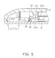
- FIG. 5is a cross-sectional view of FIG. 4 , taken along the line V-V.
- FIGS. 1-2show an electronic device in accordance with an embodiment.
- the electronic deviceincludes a cover plate 10 , a frame 30 , and a magnet 50 attached to the frame 30 .
- the electronic devicemay be a notebook computer, and the magnet 50 is configured to make the notebook computer go into stand by mode.
- the cover plate 10includes a main plate 11 .
- the main plate 11is substantially rectangular, for example.
- a positioning piece 13protrudes from the main plate 11 .
- the positioning piece 13is substantially perpendicular to the main plate 11 .
- the frame 30includes a main frame body 31 .
- the display monitoris liquid crystal display (LCD), for example.
- the main frame body 31is substantially rectangular, for example.
- a stopping piece 33is located on an outer surface of the main frame body 31 .
- the stopping piece 33is substantially perpendicular to the main frame body 31 .
- a blocking piece 35is located on the outer surface of the main frame body 31 , and one end of the blocking piece 35 is connected to one end of the stopping piece 33 .
- the blocking piece 35is substantially perpendicular to the stopping piece 33 and the main frame body 31 .
- a hook 37is located on the blocking piece 35 facing the main frame body 31 .
- the hook 37includes a resilient portion 371 and a latching portion 373 connected to the resilient portion 371 .
- the resilient portion 371extends from an edge of the stopping piece 33 and includes a limiting tab 3711 (shown in FIG. 5 ).
- the limiting tab 3711is substantially arc-shaped and protrudes towards the main frame body 31 .
- the main frame body 31 , the stopping piece 33 , and the blocking piece 35cooperatively define a receiving space 313 for receiving the magnet 50 .
- An elongated railing 39protrudes from the main frame body 31 and is located on one side of the stopping piece 33 , which faces the blocking piece 35 .
- the magnet 50includes two opposite first surfaces 51 , two opposite second surfaces 52 and two opposite third surfaces 53 .
- the magnet 50is, for example, substantially cuboid.
- the magnet 50is placed at one side of the railing 39 .
- An acting forceis applied to the hook 37 to pull the latching portion 373 away from the receiving space 313 .
- the magnet 50is pulled towards the receiving space 313 , until the magnet 50 is received in the receiving space 313 .
- the hook 37is released and the resilient portion 371 elastically rebounds to engage the latching portion 373 with the magnet 50 .
- the two first surfaces 51 of the magnet 50are engaged between the main frame body 31 and the resilient portion 371 for preventing the magnet from moving along a first direction perpendicular to the main frame body 31 .
- the two second surfaces 52 of the magnet 50are engaged between the stopping piece 33 and the limiting tab 3711 for preventing the magnet from moving along a second direction perpendicular to the first direction and the stopping piece 33 .
- the two third surfaces 53 of the magnet 50are engaged between the latching portion 373 and the blocking piece 35 for preventing the magnet 50 from moving along a third direction perpendicular to the first direction and the second direction.
- the cover plate 10is secured the frame 30 by screws for example.
- the positioning piece 13abuts the resilient portion 371 of the hook 37 from preventing the magnet 50 from disengaging from the receiving space 313 .
Landscapes
- Engineering & Computer Science (AREA)
- Computer Hardware Design (AREA)
- Theoretical Computer Science (AREA)
- Human Computer Interaction (AREA)
- Physics & Mathematics (AREA)
- General Engineering & Computer Science (AREA)
- General Physics & Mathematics (AREA)
- Casings For Electric Apparatus (AREA)
Abstract
Description
Claims (7)
Applications Claiming Priority (3)
| Application Number | Priority Date | Filing Date | Title |
|---|---|---|---|
| CN201110441192.6ACN103176519A (en) | 2011-12-26 | 2011-12-26 | Electronic device |
| CN201110441192 | 2011-12-26 | ||
| CN201110441192.6 | 2011-12-26 |
Publications (2)
| Publication Number | Publication Date |
|---|---|
| US20130163157A1 US20130163157A1 (en) | 2013-06-27 |
| US8933770B2true US8933770B2 (en) | 2015-01-13 |
Family
ID=48636467
Family Applications (1)
| Application Number | Title | Priority Date | Filing Date |
|---|---|---|---|
| US13/626,981Expired - Fee RelatedUS8933770B2 (en) | 2011-12-26 | 2012-09-26 | Electronic device with magnet |
Country Status (3)
| Country | Link |
|---|---|
| US (1) | US8933770B2 (en) |
| CN (1) | CN103176519A (en) |
| TW (1) | TW201327099A (en) |
Families Citing this family (1)
| Publication number | Priority date | Publication date | Assignee | Title |
|---|---|---|---|---|
| CN109118975B (en)* | 2018-10-15 | 2024-06-04 | 利亚德光电股份有限公司 | LED box assembly |
Citations (24)
| Publication number | Priority date | Publication date | Assignee | Title |
|---|---|---|---|---|
| US3122684A (en)* | 1961-08-10 | 1964-02-25 | Child Guidance Toys Inc | Magnetized game board configurations |
| US3598900A (en)* | 1969-06-17 | 1971-08-10 | Dracon Ind | Cover housing for telephone connectors or the like with magnetic or mechanical retaining means |
| US5301822A (en)* | 1993-02-22 | 1994-04-12 | Ullman Devices Corporation | Magnetic tool holder |
| US5367278A (en)* | 1992-09-19 | 1994-11-22 | Kabushiki Kaisha Yoshikawakun Kogyosho | Magnet holding structure |
| US5880661A (en)* | 1996-04-01 | 1999-03-09 | Emf Therapeutics, Inc. | Complex magnetic field generating device |
| US20020017793A1 (en)* | 2000-08-07 | 2002-02-14 | Georg Spiessl | Latching mechanism for the door of an electric household appliance |
| US6366440B1 (en)* | 1999-12-29 | 2002-04-02 | Compal Electronics, Inc. | Magnetic closure mechanism for a portable computer |
| US20040190239A1 (en)* | 2003-03-26 | 2004-09-30 | Shih-Lung Weng | Detachable keyboard structure |
| US6902214B2 (en)* | 2001-06-19 | 2005-06-07 | Jerry R. Smith | Electromechanical locking method and device |
| US20060087128A1 (en)* | 2003-10-15 | 2006-04-27 | Arturo Salice S.P.A. | Opening and closing latch device for furniture |
| US7277277B2 (en)* | 2004-06-28 | 2007-10-02 | Samsung Electronics Co., Ltd | Computer with a detachable main casing cover and a method of assembling same |
| US20090273906A1 (en)* | 2006-09-06 | 2009-11-05 | Peter Bohnen | Transport housing for an electronic flat module |
| US7775567B2 (en)* | 2005-12-13 | 2010-08-17 | Apple Inc. | Magnetic latching mechanism |
| US20100270817A1 (en)* | 2009-04-28 | 2010-10-28 | Hong Fu Jin Precision Industry (Shenzhen) Co., Ltd. | Collapsible device |
| US7889036B2 (en)* | 2005-03-09 | 2011-02-15 | Joachim Fiedler | Magnetic holding device |
| US8050030B2 (en)* | 2008-10-29 | 2011-11-01 | Hong Fu Jin Precision Industry (Shenzhen) Co., Ltd. | Electronic device |
| US8111120B2 (en)* | 2009-03-16 | 2012-02-07 | Asustek Computer Inc. | Electronic device |
| US8187006B2 (en)* | 2009-02-02 | 2012-05-29 | Apex Technologies, Inc | Flexible magnetic interconnects |
| US20120242093A1 (en)* | 2011-03-25 | 2012-09-27 | Chen-Yi Liang | Fixing mechanism for fixing a component |
| US20120242094A1 (en)* | 2011-03-25 | 2012-09-27 | Chen-Yi Liang | Fixing mechanism with swing operation |
| US20120268902A1 (en)* | 2011-04-22 | 2012-10-25 | Chen-Yi Liang | Fixing Mechanism and Electronic Device Having the Same |
| US20120287595A1 (en)* | 2011-05-09 | 2012-11-15 | Wistron Corporation | Electronic Device and Fixing Structure Therefor |
| US8570126B1 (en)* | 2012-09-28 | 2013-10-29 | Eaton Corporation | Contactless switch with stationary vane |
| US8587396B2 (en)* | 2011-05-09 | 2013-11-19 | Wistron Corporation | Electronic device and retaining mechanism for retaining a magnetic element of the electronic device |
- 2011
- 2011-12-26CNCN201110441192.6Apatent/CN103176519A/enactivePending
- 2011-12-28TWTW100149167Apatent/TW201327099A/enunknown
- 2012
- 2012-09-26USUS13/626,981patent/US8933770B2/ennot_activeExpired - Fee Related
Patent Citations (25)
| Publication number | Priority date | Publication date | Assignee | Title |
|---|---|---|---|---|
| US3122684A (en)* | 1961-08-10 | 1964-02-25 | Child Guidance Toys Inc | Magnetized game board configurations |
| US3598900A (en)* | 1969-06-17 | 1971-08-10 | Dracon Ind | Cover housing for telephone connectors or the like with magnetic or mechanical retaining means |
| US5367278A (en)* | 1992-09-19 | 1994-11-22 | Kabushiki Kaisha Yoshikawakun Kogyosho | Magnet holding structure |
| US5301822A (en)* | 1993-02-22 | 1994-04-12 | Ullman Devices Corporation | Magnetic tool holder |
| US5880661A (en)* | 1996-04-01 | 1999-03-09 | Emf Therapeutics, Inc. | Complex magnetic field generating device |
| US6366440B1 (en)* | 1999-12-29 | 2002-04-02 | Compal Electronics, Inc. | Magnetic closure mechanism for a portable computer |
| US20020017793A1 (en)* | 2000-08-07 | 2002-02-14 | Georg Spiessl | Latching mechanism for the door of an electric household appliance |
| US6902214B2 (en)* | 2001-06-19 | 2005-06-07 | Jerry R. Smith | Electromechanical locking method and device |
| US20040190239A1 (en)* | 2003-03-26 | 2004-09-30 | Shih-Lung Weng | Detachable keyboard structure |
| US20060087128A1 (en)* | 2003-10-15 | 2006-04-27 | Arturo Salice S.P.A. | Opening and closing latch device for furniture |
| US7277277B2 (en)* | 2004-06-28 | 2007-10-02 | Samsung Electronics Co., Ltd | Computer with a detachable main casing cover and a method of assembling same |
| US7889036B2 (en)* | 2005-03-09 | 2011-02-15 | Joachim Fiedler | Magnetic holding device |
| US7775567B2 (en)* | 2005-12-13 | 2010-08-17 | Apple Inc. | Magnetic latching mechanism |
| US20090273906A1 (en)* | 2006-09-06 | 2009-11-05 | Peter Bohnen | Transport housing for an electronic flat module |
| US8199525B2 (en)* | 2006-09-06 | 2012-06-12 | Siemens Aktiengesellschaft | Transport housing for an electronic flat module |
| US8050030B2 (en)* | 2008-10-29 | 2011-11-01 | Hong Fu Jin Precision Industry (Shenzhen) Co., Ltd. | Electronic device |
| US8187006B2 (en)* | 2009-02-02 | 2012-05-29 | Apex Technologies, Inc | Flexible magnetic interconnects |
| US8111120B2 (en)* | 2009-03-16 | 2012-02-07 | Asustek Computer Inc. | Electronic device |
| US20100270817A1 (en)* | 2009-04-28 | 2010-10-28 | Hong Fu Jin Precision Industry (Shenzhen) Co., Ltd. | Collapsible device |
| US20120242093A1 (en)* | 2011-03-25 | 2012-09-27 | Chen-Yi Liang | Fixing mechanism for fixing a component |
| US20120242094A1 (en)* | 2011-03-25 | 2012-09-27 | Chen-Yi Liang | Fixing mechanism with swing operation |
| US20120268902A1 (en)* | 2011-04-22 | 2012-10-25 | Chen-Yi Liang | Fixing Mechanism and Electronic Device Having the Same |
| US20120287595A1 (en)* | 2011-05-09 | 2012-11-15 | Wistron Corporation | Electronic Device and Fixing Structure Therefor |
| US8587396B2 (en)* | 2011-05-09 | 2013-11-19 | Wistron Corporation | Electronic device and retaining mechanism for retaining a magnetic element of the electronic device |
| US8570126B1 (en)* | 2012-09-28 | 2013-10-29 | Eaton Corporation | Contactless switch with stationary vane |
Also Published As
| Publication number | Publication date |
|---|---|
| TW201327099A (en) | 2013-07-01 |
| CN103176519A (en) | 2013-06-26 |
| US20130163157A1 (en) | 2013-06-27 |
Similar Documents
| Publication | Publication Date | Title |
|---|---|---|
| US8625258B2 (en) | Mounting apparatus for expansion card | |
| US8413945B2 (en) | Mounting apparatus for expansion card | |
| CN103000087A (en) | Display device and fixing structure for fixing display panel | |
| US8540199B2 (en) | Speaker assembly with rotary fastening mechanism | |
| US20110261285A1 (en) | Electronic device having a liquid crystal display module | |
| US8605447B2 (en) | Printed circuit board assembly | |
| US20120155008A1 (en) | Hdd mounting assembly and computer case having same | |
| US8787011B2 (en) | Mounting apparatus for expansion card | |
| US20130057804A1 (en) | Transformer | |
| US20130063677A1 (en) | Liquid crystal display | |
| US8742256B2 (en) | Electronic device enclosure | |
| US8933770B2 (en) | Electronic device with magnet | |
| US8599548B2 (en) | Mounting apparatus for PCI card bracket | |
| US9012775B2 (en) | Wire fixing structure and liquid crystal display device using the same | |
| US20110170254A1 (en) | Laptop computer display | |
| US9535463B2 (en) | Circuit board assembling structure, electronic device having the same and assembling method of electronic device | |
| US9049776B2 (en) | Latching module for housing of portable electronic device | |
| US20140085785A1 (en) | Electronic device with rubber pads | |
| US20120087083A1 (en) | Mounting apparatus for storage device | |
| US20140360952A1 (en) | Mounting apparatus for expansion cards | |
| US20140078665A1 (en) | Data storage device assembly | |
| US20120257363A1 (en) | Electronic device with fixing structure | |
| US20140140017A1 (en) | Electronic device with card bracket | |
| US20140333186A1 (en) | Mounting apparatus | |
| US20130322007A1 (en) | Data storage device assembly |
Legal Events
| Date | Code | Title | Description |
|---|---|---|---|
| AS | Assignment | Owner name:HONG FU JIN PRECISION INDUSTRY (SHENZHEN) CO., LTD Free format text:ASSIGNMENT OF ASSIGNORS INTEREST;ASSIGNORS:LIANG, WEI-KUANG;TANG, CHUN;REEL/FRAME:029033/0761 Effective date:20120925 Owner name:HON HAI PRECISION INDUSTRY CO., LTD., TAIWAN Free format text:ASSIGNMENT OF ASSIGNORS INTEREST;ASSIGNORS:LIANG, WEI-KUANG;TANG, CHUN;REEL/FRAME:029033/0761 Effective date:20120925 | |
| AS | Assignment | Owner name:SCIENBIZIP CONSULTING(SHENZHEN)CO.,LTD., CHINA Free format text:ASSIGNMENT OF ASSIGNORS INTEREST;ASSIGNORS:HONG FU JIN PRECISION INDUSTRY (SHENZHEN) CO., LTD.;HON HAI PRECISION INDUSTRY CO., LTD.;REEL/FRAME:034590/0029 Effective date:20141208 | |
| FEPP | Fee payment procedure | Free format text:MAINTENANCE FEE REMINDER MAILED (ORIGINAL EVENT CODE: REM.); ENTITY STATUS OF PATENT OWNER: SMALL ENTITY | |
| LAPS | Lapse for failure to pay maintenance fees | Free format text:PATENT EXPIRED FOR FAILURE TO PAY MAINTENANCE FEES (ORIGINAL EVENT CODE: EXP.); ENTITY STATUS OF PATENT OWNER: SMALL ENTITY | |
| STCH | Information on status: patent discontinuation | Free format text:PATENT EXPIRED DUE TO NONPAYMENT OF MAINTENANCE FEES UNDER 37 CFR 1.362 | |
| FP | Lapsed due to failure to pay maintenance fee | Effective date:20190113 |