US8932288B2 - Medical apparatus system having optical fiber load sensing capability - Google Patents
Medical apparatus system having optical fiber load sensing capabilityDownload PDFInfo
- Publication number
- US8932288B2 US8932288B2US13/096,647US201113096647AUS8932288B2US 8932288 B2US8932288 B2US 8932288B2US 201113096647 AUS201113096647 AUS 201113096647AUS 8932288 B2US8932288 B2US 8932288B2
- Authority
- US
- United States
- Prior art keywords
- distal extremity
- sensors
- catheter
- optical fiber
- distal
- Prior art date
- Legal status (The legal status is an assumption and is not a legal conclusion. Google has not performed a legal analysis and makes no representation as to the accuracy of the status listed.)
- Active, expires
Links
- 239000013307optical fiberSubstances0.000titleclaimsdescription100
- 210000000056organAnatomy0.000claimsabstractdescription34
- 239000012636effectorSubstances0.000claimsabstractdescription25
- 239000000835fiberSubstances0.000claimsabstractdescription24
- 230000002262irrigationEffects0.000claimsabstractdescription21
- 238000003973irrigationMethods0.000claimsabstractdescription21
- 238000002679ablationMethods0.000claimsabstractdescription19
- 239000012530fluidSubstances0.000claimsabstractdescription6
- 238000003745diagnosisMethods0.000claimsabstractdescription5
- 238000004891communicationMethods0.000claimsabstractdescription3
- 238000007674radiofrequency ablationMethods0.000claimsdescription5
- 238000000034methodMethods0.000abstractdescription16
- 239000011159matrix materialSubstances0.000description24
- 238000013507mappingMethods0.000description18
- 230000003287optical effectEffects0.000description13
- 239000000463materialSubstances0.000description11
- 238000005259measurementMethods0.000description10
- 238000012545processingMethods0.000description8
- 238000006243chemical reactionMethods0.000description7
- 238000010276constructionMethods0.000description7
- 230000008859changeEffects0.000description6
- 238000004519manufacturing processMethods0.000description6
- 238000003860storageMethods0.000description6
- 230000000694effectsEffects0.000description5
- 230000007613environmental effectEffects0.000description5
- 230000000737periodic effectEffects0.000description5
- 230000008602contractionEffects0.000description4
- 238000003780insertionMethods0.000description4
- 230000037431insertionEffects0.000description4
- 238000012544monitoring processMethods0.000description4
- 230000008569processEffects0.000description4
- 239000000243solutionSubstances0.000description4
- 229920000106Liquid crystal polymerPolymers0.000description3
- 239000004977Liquid-crystal polymers (LCPs)Substances0.000description3
- 239000000853adhesiveSubstances0.000description3
- 230000001070adhesive effectEffects0.000description3
- 238000005452bendingMethods0.000description3
- 230000000747cardiac effectEffects0.000description3
- 230000006835compressionEffects0.000description3
- 238000007906compressionMethods0.000description3
- 230000001419dependent effectEffects0.000description3
- 238000002001electrophysiologyMethods0.000description3
- 230000007831electrophysiologyEffects0.000description3
- 230000007246mechanismEffects0.000description3
- 230000000704physical effectEffects0.000description3
- 229920000642polymerPolymers0.000description3
- 206010072064Exposure to body fluidDiseases0.000description2
- 238000010521absorption reactionMethods0.000description2
- 230000008901benefitEffects0.000description2
- 238000004364calculation methodMethods0.000description2
- 238000001816coolingMethods0.000description2
- 238000013461designMethods0.000description2
- 239000003814drugSubstances0.000description2
- 229940079593drugDrugs0.000description2
- -1e.g.Substances0.000description2
- 238000001125extrusionMethods0.000description2
- 238000002847impedance measurementMethods0.000description2
- 238000001802infusionMethods0.000description2
- 239000007788liquidSubstances0.000description2
- 238000012986modificationMethods0.000description2
- 230000004048modificationEffects0.000description2
- 230000007935neutral effectEffects0.000description2
- 238000004806packaging method and processMethods0.000description2
- 238000002604ultrasonographyMethods0.000description2
- 230000000007visual effectEffects0.000description2
- 206010003658Atrial FibrillationDiseases0.000description1
- 208000006017Cardiac TamponadeDiseases0.000description1
- 239000004696Poly ether ether ketoneSubstances0.000description1
- 239000004698PolyethyleneSubstances0.000description1
- 239000004642PolyimideSubstances0.000description1
- FAPWRFPIFSIZLT-UHFFFAOYSA-MSodium chlorideChemical compound[Na+].[Cl-]FAPWRFPIFSIZLT-UHFFFAOYSA-M0.000description1
- RTAQQCXQSZGOHL-UHFFFAOYSA-NTitaniumChemical compound[Ti]RTAQQCXQSZGOHL-UHFFFAOYSA-N0.000description1
- JUPQTSLXMOCDHR-UHFFFAOYSA-Nbenzene-1,4-diol;bis(4-fluorophenyl)methanoneChemical compoundOC1=CC=C(O)C=C1.C1=CC(F)=CC=C1C(=O)C1=CC=C(F)C=C1JUPQTSLXMOCDHR-UHFFFAOYSA-N0.000description1
- 239000012867bioactive agentSubstances0.000description1
- 229920000249biocompatible polymerPolymers0.000description1
- 239000008280bloodSubstances0.000description1
- 210000004369bloodAnatomy0.000description1
- 210000001124body fluidAnatomy0.000description1
- 238000009529body temperature measurementMethods0.000description1
- 238000013153catheter ablationMethods0.000description1
- 238000012512characterization methodMethods0.000description1
- 239000011248coating agentSubstances0.000description1
- 238000000576coating methodMethods0.000description1
- 230000001427coherent effectEffects0.000description1
- 238000005520cutting processMethods0.000description1
- 230000008021depositionEffects0.000description1
- 230000001066destructive effectEffects0.000description1
- 229920001746electroactive polymerPolymers0.000description1
- 239000003292glueSubstances0.000description1
- 230000005484gravityEffects0.000description1
- 230000036039immunityEffects0.000description1
- 230000001939inductive effectEffects0.000description1
- 238000002347injectionMethods0.000description1
- 239000007924injectionSubstances0.000description1
- 208000014674injuryDiseases0.000description1
- 230000003993interactionEffects0.000description1
- 238000005304joiningMethods0.000description1
- 238000000608laser ablationMethods0.000description1
- 208000003173lipoprotein glomerulopathyDiseases0.000description1
- 238000002355open surgical procedureMethods0.000description1
- 230000037361pathwayEffects0.000description1
- 229920000052poly(p-xylylene)Polymers0.000description1
- 229920003223poly(pyromellitimide-1,4-diphenyl ether)Polymers0.000description1
- 229920002530polyetherether ketonePolymers0.000description1
- 229920000573polyethylenePolymers0.000description1
- 229920001721polyimidePolymers0.000description1
- 230000001681protective effectEffects0.000description1
- 230000005855radiationEffects0.000description1
- 230000009467reductionEffects0.000description1
- 230000000250revascularizationEffects0.000description1
- 239000011780sodium chlorideSubstances0.000description1
- 239000007787solidSubstances0.000description1
- 238000001356surgical procedureMethods0.000description1
- 230000001225therapeutic effectEffects0.000description1
- 238000002560therapeutic procedureMethods0.000description1
- 229910052719titaniumInorganic materials0.000description1
- 239000010936titaniumSubstances0.000description1
- 238000012876topographyMethods0.000description1
- 230000008733traumaEffects0.000description1
- 238000012800visualizationMethods0.000description1
Images


Classifications
- A—HUMAN NECESSITIES
- A61—MEDICAL OR VETERINARY SCIENCE; HYGIENE
- A61B—DIAGNOSIS; SURGERY; IDENTIFICATION
- A61B5/00—Measuring for diagnostic purposes; Identification of persons
- A61B5/0059—Measuring for diagnostic purposes; Identification of persons using light, e.g. diagnosis by transillumination, diascopy, fluorescence
- A61B5/0082—Measuring for diagnostic purposes; Identification of persons using light, e.g. diagnosis by transillumination, diascopy, fluorescence adapted for particular medical purposes
- A61B5/0084—Measuring for diagnostic purposes; Identification of persons using light, e.g. diagnosis by transillumination, diascopy, fluorescence adapted for particular medical purposes for introduction into the body, e.g. by catheters
- A—HUMAN NECESSITIES
- A61—MEDICAL OR VETERINARY SCIENCE; HYGIENE
- A61B—DIAGNOSIS; SURGERY; IDENTIFICATION
- A61B90/00—Instruments, implements or accessories specially adapted for surgery or diagnosis and not covered by any of the groups A61B1/00 - A61B50/00, e.g. for luxation treatment or for protecting wound edges
- A61B90/90—Identification means for patients or instruments, e.g. tags
- A61B90/98—Identification means for patients or instruments, e.g. tags using electromagnetic means, e.g. transponders
- A61B19/46—
- A—HUMAN NECESSITIES
- A61—MEDICAL OR VETERINARY SCIENCE; HYGIENE
- A61B—DIAGNOSIS; SURGERY; IDENTIFICATION
- A61B5/00—Measuring for diagnostic purposes; Identification of persons
- A61B5/0059—Measuring for diagnostic purposes; Identification of persons using light, e.g. diagnosis by transillumination, diascopy, fluorescence
- A61B5/0062—Arrangements for scanning
- A61B5/0066—Optical coherence imaging
- A—HUMAN NECESSITIES
- A61—MEDICAL OR VETERINARY SCIENCE; HYGIENE
- A61B—DIAGNOSIS; SURGERY; IDENTIFICATION
- A61B5/00—Measuring for diagnostic purposes; Identification of persons
- A61B5/02—Detecting, measuring or recording for evaluating the cardiovascular system, e.g. pulse, heart rate, blood pressure or blood flow
- A61B5/02007—Evaluating blood vessel condition, e.g. elasticity, compliance
- A—HUMAN NECESSITIES
- A61—MEDICAL OR VETERINARY SCIENCE; HYGIENE
- A61B—DIAGNOSIS; SURGERY; IDENTIFICATION
- A61B5/00—Measuring for diagnostic purposes; Identification of persons
- A61B5/68—Arrangements of detecting, measuring or recording means, e.g. sensors, in relation to patient
- A61B5/6846—Arrangements of detecting, measuring or recording means, e.g. sensors, in relation to patient specially adapted to be brought in contact with an internal body part, i.e. invasive
- A61B5/6847—Arrangements of detecting, measuring or recording means, e.g. sensors, in relation to patient specially adapted to be brought in contact with an internal body part, i.e. invasive mounted on an invasive device
- A61B5/6852—Catheters
- A—HUMAN NECESSITIES
- A61—MEDICAL OR VETERINARY SCIENCE; HYGIENE
- A61B—DIAGNOSIS; SURGERY; IDENTIFICATION
- A61B5/00—Measuring for diagnostic purposes; Identification of persons
- A61B5/68—Arrangements of detecting, measuring or recording means, e.g. sensors, in relation to patient
- A61B5/6846—Arrangements of detecting, measuring or recording means, e.g. sensors, in relation to patient specially adapted to be brought in contact with an internal body part, i.e. invasive
- A61B5/6885—Monitoring or controlling sensor contact pressure
- A—HUMAN NECESSITIES
- A61—MEDICAL OR VETERINARY SCIENCE; HYGIENE
- A61B—DIAGNOSIS; SURGERY; IDENTIFICATION
- A61B90/00—Instruments, implements or accessories specially adapted for surgery or diagnosis and not covered by any of the groups A61B1/00 - A61B50/00, e.g. for luxation treatment or for protecting wound edges
- A61B90/06—Measuring instruments not otherwise provided for
- A—HUMAN NECESSITIES
- A61—MEDICAL OR VETERINARY SCIENCE; HYGIENE
- A61B—DIAGNOSIS; SURGERY; IDENTIFICATION
- A61B90/00—Instruments, implements or accessories specially adapted for surgery or diagnosis and not covered by any of the groups A61B1/00 - A61B50/00, e.g. for luxation treatment or for protecting wound edges
- A61B90/90—Identification means for patients or instruments, e.g. tags
- A61B90/94—Identification means for patients or instruments, e.g. tags coded with symbols, e.g. text
- A61B90/96—Identification means for patients or instruments, e.g. tags coded with symbols, e.g. text using barcodes
- A—HUMAN NECESSITIES
- A61—MEDICAL OR VETERINARY SCIENCE; HYGIENE
- A61B—DIAGNOSIS; SURGERY; IDENTIFICATION
- A61B18/00—Surgical instruments, devices or methods for transferring non-mechanical forms of energy to or from the body
- A61B18/04—Surgical instruments, devices or methods for transferring non-mechanical forms of energy to or from the body by heating
- A61B18/12—Surgical instruments, devices or methods for transferring non-mechanical forms of energy to or from the body by heating by passing a current through the tissue to be heated, e.g. high-frequency current
- A61B18/14—Probes or electrodes therefor
- A61B18/1492—Probes or electrodes therefor having a flexible, catheter-like structure, e.g. for heart ablation
- A61B19/2203—
- A—HUMAN NECESSITIES
- A61—MEDICAL OR VETERINARY SCIENCE; HYGIENE
- A61B—DIAGNOSIS; SURGERY; IDENTIFICATION
- A61B17/00—Surgical instruments, devices or methods
- A61B2017/00017—Electrical control of surgical instruments
- A61B2017/00022—Sensing or detecting at the treatment site
- A61B2017/00039—Electric or electromagnetic phenomena other than conductivity, e.g. capacity, inductivity, Hall effect
- A61B2017/00044—Sensing electrocardiography, i.e. ECG
- A61B2017/00048—Spectral analysis
- A61B2017/00053—Mapping
- A—HUMAN NECESSITIES
- A61—MEDICAL OR VETERINARY SCIENCE; HYGIENE
- A61B—DIAGNOSIS; SURGERY; IDENTIFICATION
- A61B17/00—Surgical instruments, devices or methods
- A61B2017/00017—Electrical control of surgical instruments
- A61B2017/00022—Sensing or detecting at the treatment site
- A61B2017/00084—Temperature
- A61B2019/2211—
- A61B2019/442—
- A61B2019/448—
- A61B2019/465—
- A61B2019/547—
- A—HUMAN NECESSITIES
- A61—MEDICAL OR VETERINARY SCIENCE; HYGIENE
- A61B—DIAGNOSIS; SURGERY; IDENTIFICATION
- A61B34/00—Computer-aided surgery; Manipulators or robots specially adapted for use in surgery
- A61B34/20—Surgical navigation systems; Devices for tracking or guiding surgical instruments, e.g. for frameless stereotaxis
- A61B2034/2046—Tracking techniques
- A61B2034/2061—Tracking techniques using shape-sensors, e.g. fiber shape sensors with Bragg gratings
- A—HUMAN NECESSITIES
- A61—MEDICAL OR VETERINARY SCIENCE; HYGIENE
- A61B—DIAGNOSIS; SURGERY; IDENTIFICATION
- A61B34/00—Computer-aided surgery; Manipulators or robots specially adapted for use in surgery
- A61B34/30—Surgical robots
- A61B2034/301—Surgical robots for introducing or steering flexible instruments inserted into the body, e.g. catheters or endoscopes
- A—HUMAN NECESSITIES
- A61—MEDICAL OR VETERINARY SCIENCE; HYGIENE
- A61B—DIAGNOSIS; SURGERY; IDENTIFICATION
- A61B90/00—Instruments, implements or accessories specially adapted for surgery or diagnosis and not covered by any of the groups A61B1/00 - A61B50/00, e.g. for luxation treatment or for protecting wound edges
- A61B90/06—Measuring instruments not otherwise provided for
- A61B2090/064—Measuring instruments not otherwise provided for for measuring force, pressure or mechanical tension
- A61B2090/065—Measuring instruments not otherwise provided for for measuring force, pressure or mechanical tension for measuring contact or contact pressure
- A—HUMAN NECESSITIES
- A61—MEDICAL OR VETERINARY SCIENCE; HYGIENE
- A61B—DIAGNOSIS; SURGERY; IDENTIFICATION
- A61B90/00—Instruments, implements or accessories specially adapted for surgery or diagnosis and not covered by any of the groups A61B1/00 - A61B50/00, e.g. for luxation treatment or for protecting wound edges
- A61B90/39—Markers, e.g. radio-opaque or breast lesions markers
- A61B2090/397—Markers, e.g. radio-opaque or breast lesions markers electromagnetic other than visible, e.g. microwave
- A—HUMAN NECESSITIES
- A61—MEDICAL OR VETERINARY SCIENCE; HYGIENE
- A61B—DIAGNOSIS; SURGERY; IDENTIFICATION
- A61B2562/00—Details of sensors; Constructional details of sensor housings or probes; Accessories for sensors
- A61B2562/02—Details of sensors specially adapted for in-vivo measurements
- A61B2562/0261—Strain gauges
- A61B2562/0266—Optical strain gauges
- A—HUMAN NECESSITIES
- A61—MEDICAL OR VETERINARY SCIENCE; HYGIENE
- A61B—DIAGNOSIS; SURGERY; IDENTIFICATION
- A61B34/00—Computer-aided surgery; Manipulators or robots specially adapted for use in surgery
- A61B34/30—Surgical robots
Definitions
- the present inventionrelates to apparatus for exploring and treating an organ that permits computation of a multi-dimensional force vector resulting from contact between the distal extremity of the apparatus and the tissue of the wall of the organ.
- catheter-based diagnostic and treatment systemsFor many years, exploration and treatment of various organs or vessels has been possible using catheter-based diagnostic and treatment systems. Such catheters are introduced through a vessel leading to the cavity of the organ to be explored or treated or alternatively may be introduced directly through an incision made in the wall of the organ. In this manner, the patient avoids the trauma and extended recuperation times typically associated with open surgical procedures.
- mappingmay be performed, for example, when it is desired to selectively ablate current pathways within a heart to treat atrial fibrillation. Often, the mapping procedure is complicated by difficulties in locating the zone(s) to be treated due to periodic movement of the heart throughout the cardiac cycle.
- mapping systemsrely on manual feedback of the catheter and/or impedance measurements to determine when the catheter is properly positioned in the vessel or organ. Those systems do not measure contact forces with the vessel or organ wall or detect contact forces applied by the catheter against the organ or vessel wall that may modify the true wall location. Instead, previously known mapping methods are time-consuming, dependent upon the skill of the clinician, and cannot compensate for artifacts created by excessive contact forces.
- the cathetermay comprise any of a number of end effectors, such as RF ablation electrodes, a rotary cutting head, laser ablation system, injection needle or cryogenic fluid delivery system. Exemplary systems are described, for example, in U.S. Pat. Nos. 6,120,520, 6,102,926, 5,575,787, 5,409,000 and 5,423,807.
- the creation of a gap between the end effector of the treatment system and the tissue wallmay render the treatment ineffective, and inadequately ablate the tissue zone.
- the end effector of the cathetercontacts the tissue wall with excessive force, if may inadvertently puncture the tissue, resulting in cardiac tamponade.
- a catheter-based diagnostic or treatment systemthat permits sensing of the load applied to the distal extremity of the catheter, including periodic loads arising from movement of the organ or tissue. It further would be desirable to have a load sensing system coupled to control operation of the end effector, so that the end effector is operated, either manually or automatically, only when the contact force is detected to fall within a predetermined range.
- U.S. Pat. No. 6,695,808proposes several solutions to measure the force vector arising from contact with the tissue surface, including mechanical, capacitive, inductive and resistive pressure sensing devices.
- One drawback of such devicesis that they are relatively complex and must be sealed to prevent blood or other liquids from disturbing the measurements.
- load sensing devicesmay result in an increase in the insertion profile of the distal extremity of the catheter.
- sensors of the types described in that patentmay be subject to electromagnetic interference.
- diagnostic and treatment apparatussuch as a catheter or guide wire, that permits sensing of loads applied to a distal extremity of the apparatus, but which do not substantially increase the insertion profile of the apparatus.
- diagnostic and treatment apparatussuch as a catheter and guide wire, that permits computation of forces applied to a distal extremity of the apparatus, and which are substantially immune to electromagnetic interference.
- a diagnostic and treatment apparatussuch as catheter system, that permits computation of forces applied to a distal extremity of the catheter that is substantially immune to environmental conditions encountered during use of the catheter, such as exposure to body fluids and the presence of room-to-body temperature gradients.
- an interventional apparatussuch as a mapping catheter or guide wire
- medical apparatussuch as catheter, having at least two optical fiber sensors disposed in a distal extremity configured to deform responsive to contact forces, and processing logic programmed to compute at least a two-dimensional force vector responsive to detected changes in the optical characteristics of the optical fiber sensors.
- the apparatus of the present inventionmay be configured as a catheter or guide wire, or may be employed in other medical apparatus where knowledge of tissue contact forces is desired.
- the apparatus of the present inventioncomprises three optical fiber sensors disposed within the distal extremity so that they are not co-planar.
- the three optical fiber sensorsmay be arranged at the apices of an equilateral triangle centered on the geometric axis of the apparatus, although other configurations also may be employed.
- Use of three such optical fiber sensorsadvantageously permits the computation of a three-dimensional force vector.
- the optical fiber sensorspreferably are chosen from among a Fiber Bragg Grating (FBG), an Intrinsic Fabry-Perot Interferometer (IFPI), an Extrinsic Fabry-Perot Interferometer (EFPI), a Long Period Grating (LPG), a two, three or four arm Michelson interferometer (MI), a Brillouin scattering strain sensor, or intensity-based fiber optic strain sensor.
- FBGFiber Bragg Grating
- IFPIIntrinsic Fabry-Perot Interferometer
- EFPIExtrinsic Fabry-Perot Interferometer
- LPGLong Period Grating
- MIMichelson interferometer
- Brillouin scattering strain sensoror intensity-based fiber optic strain sensor.
- the apparatusincludes processing logic, such as programmed general purpose microprocessor or application specific integrated circuit, operatively coupled to receive an output signal from the optical fiber sensors, and to compute a two- or three-dimensional force vector from that output signal, depending upon the number of optical fiber sensors employed.
- the processing logicmay be programmed with a matrix of values associated with physical properties of an individual device, and applies those values to the detected changes in wavelength to compute the external forces applied to the distal extremity. More preferably, a force-strain conversion matrix specific for each device is determined during manufacture, and that force-strain conversion is associated with the device via an appropriate memory device, label or tag.
- two optical fiber sensorsmay be used provided that the neutral axis of the distal extremity of the apparatus is well characterized. More preferably, three optical fiber sensors are disposed within the distal extremity to allow deformations (elongation or contraction) imposed on the deformable body to be measured at three or more non-planar points.
- the optical fiber sensorsprovide ample space in the distal extremity of the apparatus to house for other diagnostic or treatment devices.
- the deviceWhen configured as a catheter or guide wire, the device has a substantially reduced insertion profile relative to previously-known systems having force-sensing capability.
- the optical nature of the sensorsensures that the possible presence of liquids does not disturb the measurements, and ensures a high degree of immunity from electromagnetic interference.
- the apparatus of the present inventionoptionally may include any of a number of previously-known end effectors disposed in the distal extremity for treating a vessel or organ, for example, an electrode to measure an electric potential (e.g., to perform an endocavity electrocardiogram), an electrode configured to ablate tissue by deposition of radiofrequency energy, an irrigation channel, and/or a three-dimensional positioning sensor.
- an electrode to measure an electric potentiale.g., to perform an endocavity electrocardiogram
- an electrodeconfigured to ablate tissue by deposition of radiofrequency energy
- an irrigation channele.g., to perform an endocavity electrocardiogram
- a three-dimensional positioning sensore.g., a three-dimensional positioning sensor.
- the load sensing system of the present inventionmay be employed to continuously monitor deflection of a distal extremity.
- the signal output by the load sensing systemmay be used to guide or control the use and operation of an end effector of a catheter either manually or automatically.
- the present inventionpermits electrical potentials of the tissue to be measured only at contact positions where the contact force applied to the distal extremity of the catheter by the tissue wall falls within a predetermined range. Such an arrangement not only offers to improve spatial registration between the mapped values and tissue location, but also makes possible the use of robotic systems capable of automating the mapping process.
- the output of the load sensing systemmay be used to control operation of a treatment end effector, for example, to position the end effector in contact with the organ wall and to energize the ablation electrode only when the contact force is detected to fall within a predetermined range.
- the distal part of at least one of the optical fibers, or an additional optical fiberextends beyond the others and is equipped with an additional FBG, LPG, IFPI, EFPI or Brillouin scattering type sensor to permit the temperature of the distal extremity to be monitored.
- a temperature sensormay be disposed in the distal extremity in close proximity to the optical fiber sensors. Temperatures measured by the temperature sensor may be used to compensate for deformations of the deformable body arising from temperature variations, which might otherwise erroneously be interpreted as force-related deformations.
- the temperature sensormay comprise any of a number of temperature sensors. More specifically, the temperature sensor comprises an additional optic fiber that is not constrained to deform in unison with the distal extremity, but instead is free to expand due to temperature variations. In a preferred embodiment, the temperature sensor comprises an additional FBG, LPG, IFPI, EFPI or Brillouin scattering type optical fiber sensor.
- the additional optical fiberalso could extend beyond the other optical fibers and include an additional FBG, LPG, IFPI, EFPI or Brillouin scattering type sensor to measure the temperature of the distal extremity.
- the distal part of the additional fiberextends beyond the other optical fibers in the distal extremity and includes a temperature sensor comprising a Michelson interferometer sensor or an intensity sensor.
- the apparatusmay comprise an electrophysiology catheter comprising an elongated portion, a distal extremity, and a proximal end.
- An irrigation tubeextends from the proximal end to the distal extremity and has a plurality of optical fibers arranged symmetrically around its circumference.
- the optical fibersinclude sensors, such as Bragg Gratings, disposed near the distal extremity.
- the irrigation tube in the vicinity of the distal extremitycomprises a flexible tube having a low thermal expansion coefficient which reduces sensor artifacts introduced by environmental effects, such a temperature fluctuations.
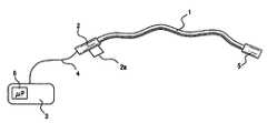
- FIG. 1is a schematic view of apparatus according to the invention
- FIG. 2is a schematic plan view of the distal extremity of FIG. 1 ;
- FIG. 3is a section according to of FIG. 2 ;
- FIG. 4is a schematic view of the side of the distal extremity showing the disposition of the Fiber Bragg Grating (FBG) or Long Period Grating (LPG) sensors;
- FBGFiber Bragg Grating
- LPGLong Period Grating
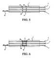
- FIG. 5is a schematic view of the side of the distal extremity showing the disposition of the Intrinsic Fabry-Perot Interferometer (IFPI) sensors;
- IFPIIntrinsic Fabry-Perot Interferometer
- FIG. 6is a schematic view of the side of the distal extremity showing the disposition of the Extrinsic Fabry-Perot Interferometer (EFPI) sensors;
- EFPIExtrinsic Fabry-Perot Interferometer
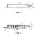
- FIG. 7is a schematic view of the side of the distal extremity showing the disposition of the Michelson interferometer sensors
- FIG. 8is a schematic view of the side of the distal extremity showing the disposition of the High Resolution Brillouin sensors
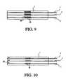
- FIG. 9is a schematic view of the side of the distal extremity showing the disposition of the reflection intensity sensors
- FIG. 10is a schematic view of the side of the distal extremity showing the disposition of the microbending intensity sensors
- FIG. 11is a perspective view of three optical fibers in contact with each other;
- FIG. 12is a perspective view of three optical fibers in contact with each other and forming an integral part
- FIG. 13is a schematic plan view of the distal extremity with the optical fibers of FIG. 6 forming an integral part of the distal extremity;
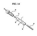
- FIG. 14is an exploded perspective view of the distal extremity of an exemplary catheter constructed in accordance with the present invention.
- FIG. 15is a schematic plan view of the distal extremity including a fourth optical fiber
- FIG. 16is a schematic view of apparatus of the present invention wherein the output of the load sensing system is utilized to control automated operation of the apparatus;
- FIG. 17is a schematic view of an alternative embodiment of apparatus of the present application.
- FIG. 18is a perspective view of a distal subassembly of the apparatus of FIG. 17 ;
- FIG. 19is a perspective view of the distal subassembly of FIG. 18 including a protective housing, which is partially cut-away;
- FIG. 20is a cross-sectional view of the distal subassembly of FIG. 19 taken along line 20 - 20 ;
- FIG. 21is a perspective view of an exemplary deflectable catheter shaft for use with the distal subassembly of FIG. 19 .
- the present inventionis directed to medical apparatus and methods for use with diagnostic and treatment systems wherein it is desired to measure contact forces between a distal extremity of the apparatus and a tissue wall of an organ or vessel.
- the load sensing capability of the present inventionmay be used intermittently to measure the contact forces at discrete points, or alternatively, used to continuously monitor contact forces to assist in manipulation and operation of the apparatus.
- Medical apparatus incorporating the present inventionillustratively may be configured as catheters or guide wires to be manually manipulated by a clinician, with the clinician using a visual or audio cue output by the load sensing system to determine, for example, optimum position for measuring an electrophysiologic value or performing treatment.
- the medical apparatusmay be robotically controlled, with the load sensing system of the present invention providing a feedback and control system.
- medical apparatus equipped with the load sensing system of the present inventionare expected to permit faster, more accurate diagnosis or treatment of a vessel of organ, with improved registration between measured values and spatial locations.
- a catheter with the inventive load sensing systemwould permit mapping of cardiac electrical potentials by providing reproducible contact forces between the distal extremity of the catheter and the tissue wall, thereby making the results of the mapping process less dependent on the skill of the individual clinician and facilitating automated procedures.
- exemplary apparatus constructed in accordance with the principles of the present inventioncomprises catheter 1 having proximal end 2 coupled to console 3 via cable 4 .
- catheter 1includes distal extremity 5 that illustratively carries any one or more of a number of end effectors known in the art for diagnosing or treating a vessel or organ. While the present invention is described in the context of a catheter system for cardiac mapping and ablation, it will be understood that medical apparatus constructed in accordance with the present invention advantageously may be used for other purposes, such as delivering drugs or bioactive agents to a vessel or organ wall or performing transmyocardial revascularization or cryo-ablation, such as described in the above-referenced patents.
- Proximal end 2preferably includes storage device 2 a, such as a memory chip, RFID tag or bar code label, which stores data that may be used in computing a multi-dimensional force vector, as described herein after.
- storage device 2 aneed not be affixed to proximal end 2 , but instead could be a separate item, e.g., packaging, individually associated with each catheter.
- Proximal end 2may be manipulated manually or automatically to cause a desired amount of articulation or flexion of distal extremity 5 using mechanisms which are per se known in the art, such as pull wires or suitably configured electroactive polymers.
- Catheter 1also may be advanced, retracted and turned manually or automatically.
- Distal extremity 5 of catheter 1comprises a deformable body having at least two optical fiber sensors that extend proximally and are coupled to console 3 via proximal end 2 and cable 4 . More preferably, catheter 1 includes three optical fiber sensors disposed therein. In addition, control signals to and from the end effector(s) in distal extremity 5 are transmitted via suitable components of cable 4 to console 3 , to a tactile component of proximal end 2 . As will be apparent, the nature of cable 4 depends on the nature of the end effectors disposed in distal extremity 5 of catheter 1 .
- Console 3comprises electronic and optical components to drive the optical fiber sensors and to interpret the output signals therefrom.
- Console 3further includes processing logic 6 , such as a programmed general purpose microprocessor or application-specific integrated circuit, which receives an output signal corresponding to wavelength changes manifested in the optical fiber sensors due to forces applied to the distal extremity of the deformable body.
- Processing logic 6computes a multi-dimensional force vector based upon that output signal and a matrix of physical characteristics of the individual deformable body, as described in detail below.
- Console 3preferably also includes means to manifest an output from the load sensing system, such as a visual display or an auditory device. Alternatively, console 3 may output a signal for display on a separate monitor.
- catheter 1preferably has at least two optical fiber sensors 7 disposed within it, so that deformation of distal extremity 5 is transferred to the sensors 7 .
- Two optical fiber sensorsmay be employed so long as the location of the neutral axis of the distal extremity is known or determined during manufacture.
- distal extremity 1includes at least three optical fiber sensors, and comprises a molded, machined or extruded material, such as typically are used in making guide wires or catheters.
- the optical fibersmay be affixed within the distal extremity using adhesive or other means as, for example, overmolding or co-extrusion.
- adhesive 8optical fibers 7 are glued into distal extremity 5 using adhesive 8 .
- catheter 1comprises a liquid crystal polymer (“LCP”) that has a small positive or even negative coefficient of thermal expansion in the direction of extrusion.
- LCPliquid crystal polymer
- a variety of liquid crystal polymersare known in the art and such materials may be coated with parylene or a metallic coating to enhance resistance to fluid absorption.
- optical fibers 7are disposed in distal extremity 5 so that the optical fiber sensors are not co-planar, i.e., are not situated in a single plane.
- the optical fibersare disposed at the apices of an equilateral triangle centered on the longitudinal axis of the catheter.
- Other configurationsare possible, so long as optical fibers experience different degrees of bending and elongation during deformation of distal extremity 5 .
- Optical fiber sensors 7may be chosen from among a Fiber Bragg Grating (FBG), a Long Period Grating (LPG), an Intrinsic Fabry-Perot Interferometer (IFPI), an Extrinsic Fabry-Perot Interferometer (EFPI), a two, three or four arm Michelson interferometer (MI), a Brillouin scattering strain sensor, or intensity-based fiber optic strain sensor.
- FBGFiber Bragg Grating
- LPGLong Period Grating
- IFPIIntrinsic Fabry-Perot Interferometer
- EFPIExtrinsic Fabry-Perot Interferometer
- MIMichelson interferometer
- MIBrillouin scattering strain sensor
- intensity-based fiber optic strain sensorintensity-based fiber optic strain sensor
- catheter 1is depicted housing three optical fibers 7 having FBG or LPG strain sensors 9 disposed in distal extremity 5 .
- An FBG sensoris an interferometer in which a stable Bragg grating is permanently impressed (e.g., photo-etched) into the core of the fiber.
- the region of periodic variation in the index of refraction of the fiber coreacts as a very narrowband reflection filter that reflects light having a predetermined Bragg wavelength. Light therefore is reflected from the FBG in a narrow spike with a center wavelength that is linearly dependent on the Bragg wavelength and the mean index of refraction of the core. Consequently, deformations that alter the grating characteristics result in a shift in the reflected Bragg wavelength.
- An LPGis similar in construction to an FBG, and comprises a single mode fiber having periodic index modulation of the refractive index of the fiber core with a much longer period than an FBG.
- Use and operation of a catheter employing LPGs rather than FBGsis similar to that described below.
- the distal extremity of catheter 1is compressed and bent due to loads imposed by contacting the tissue of the organ.
- the portions of optical fibers 7 that are situated in the distal extremityalso are deformed but in a varying degrees according to their respective positions in the distal extremity.
- the distal extremitymay be deflected by deflecting a more proximal portion of the catheter using any of a variety of previously-known catheter deflection mechanisms, such as described in U.S. Pat. No. 4,960,134 to Webster, which is incorporated herein by reference.
- the apparatuswill compute the force with which the distal extremity contacts the tissue of the organ or vessel.
- the initial calibration of the FBG sensorsi.e., the average wavelength reflected from the Bragg grating in the absence of any applied forces (referred to as the “Bragg wavelength”) is determined from grating characteristics impressed during manufacture of the optical fiber. Any deviations from the Bragg wavelength are proportionately related to an exact parameter, such as strain.
- the Bragg gratingallows the deformation (elongation or contraction) of each of optical fibers 7 to be quantified by measuring the change in wavelength of the light reflected by the Bragg grating.
- the foregoing informationtogether with known physical properties of the distal extremity of the catheter, enable processing logic 6 of console 3 to calculate the components of a multidimensional force vector with appropriate algorithms.
- the force vectorthen may be displayed or otherwise manifested, for example, as a graphic on a display screen or by varying the pitch emitted from an auditory device housed in or associated with console 3 .
- one of optical fibers 7preferably extends beyond the others and includes second FBG (or LPG) 10 for measuring the temperature of the front end of the distal extremity. Temperature changes at the front end of the distal extremity may arise, e.g., due to operation of an ablation electrode, and will cause a change in the associated Bragg wavelength.
- processing logic 6may compute the temperature at the level of the distal extremity, for example, to monitor tissue ablation progress.
- console 3comprises a laser, preferably a tunable laser diode, arranged to inject a beam of light into the optical fibers through cable 4 , and a photodetector that detects variations in the characteristics of the reflected light beam due to deformations imposed on the strain sensors and distal extremity 5 .
- console 3includes a Fiber Bragg Grating Demodulator.
- each of the optical fiber sensorshas a Bragg grating with a different wavelength, and which therefore responds in a specified range of frequency.
- a tunable laseris coupled to all of the optical fiber sensors and scans a certain frequency several times per second.
- a photodioderecords the wavelength change for each Bragg grating when the frequency of the laser centers on the grating frequency. In this manner, each of the optical fiber sensors may be interrogated as the tunable laser scans through the grating frequencies of the sensors.
- processing logic 6is programmed to compute a two- or three-dimensional force vector from the output of the Fiber Bragg Grating Demodulator. The theory underlying these computations is now described.
- the total strainmay be computed using:
- the total strainincludes a component due to thermal expansion of the distal extremity arising from the difference between the measured temperature of the distal extremity and a predetermined reference temperature.
- the elastic strainwhich is a function of the applied force, therefore may be calculated using:
- the elastic strainsare related to the internal forces experienced by the optical fiber sensors as a function of both the physical dimensions of, and the material properties of, the distal extremity:
- Equation (2.1)may be rearranged to solve for the internal forces as a function of the elastic strain.
- the elastic strain from equation (1.3)may then be substituted into the rearranged matrix system to compute the internal forces as a function of the elastic strain, as shown in Equation (2.3) below:
- storage device 2 amay comprise a memory chip associated with cable 4 in which such information is stored, or a bar code or a RFID tag located on proximal end 2 of the catheter or the packaging for the catheter.
- data specific to an individual cathetermay be uploaded to console 3 from an item of removable storage (e.g., CD) or via secure download from the manufacturer's website.
- the information specific to each cathetermay be obtained during a calibration step, conducted during manufacture of the catheter, by subjecting the distal extremity of the catheter to a series of known forces.
- F(t)is the vector of forces [F x,t , F y,t , F z,t ],
- ⁇ (t)is the vector of wavelengths [ ⁇ 1,t , ⁇ 2,t , ⁇ 3,t ] measured for the individual sensors,
- ⁇ 0is the vector of wavelengths [ ⁇ 0 1 , ⁇ 0 2 , ⁇ 0 3 ] measured for the individual sensors with zero applied force
- Kis a matrix computed when the deformable body is subjected to the series of known forces.
- the catheteris subjected to the following forces in series: (1) a purely axial force of known magnitude F′; (2) a lateral force of known magnitude F′′; and (3) a lateral force of known magnitude F′′′ applied 90 degrees to the orientation of force F′′.
- Force-to-strain conversion matrix Kthen may be stored in storage device 2 a associated with the corresponding device, as described herein above.
- the values of the force-to-conversion matrixthen may be input to console 3 when the catheter is coupled to the console using a bar code reader, input pad or direct electrical connection through cable 4 .
- matrix KOnce matrix K is provided for a given distal extremity, the normal force, transverse force and angle of application of the transverse force may be computed as described above and using Table I.
- the values for the normal force, transverse force and angle of application of the transverse force, computed as described above,may be output as numerical values to a display monitor that forms part of console 3 or which is associated with console 3 .
- a graphic including a variable size or colored arrowmay be displayed pointing at a position on the circumference of a circle to visualize the magnitude and direction of the transverse force applied to the distal extremity. By monitoring this display, the operator may continuously obtain feedback concerning the contact forces applied to the distal extremity of the catheter.
- optical fiber strain sensors 7comprise Intrinsic Fabry-Perot Interferometers (IFPI).
- IFPIIntrinsic Fabry-Perot Interferometers
- One of the optical fibersis extended and comprises a second IFPI sensor 13 for measuring the temperature of the front end of the distal extremity.
- An IFPIcomprises a single mode optical fiber having segment having reflectors 12 disposed at either end to define optical cavity 11 .
- the reflectorsmay comprise semi-reflective mirror surfaces formed in the fiber, or alternatively may comprise two FBGs.
- Light emitted from a laser diode disposed in console 3impinges upon the proximal reflector and is partially reflected back at specific wavelengths 14 .
- Light passing through the proximal reflector and impinging upon the distal reflectoris also reflected back.
- the two reflected beamsresult in constructive and destructive interferences that are detected by a photodetector disposed in console 3 .
- a variation in strain or temperaturechanges the optical length of optical cavity 11 and sensor 13 , and influences the reflection characteristics from which relative deflections of the optical fibers may be computed. This information in turn permits computation of the force vector imposed upon distal extremity 5 due to contact with the tissue of the wall of the organ or vessel.
- FIG. 6illustrates a further alternative embodiment of the distal extremity of catheter 1 and contains three Extrinsic Fabry-Perot interferometer (EFPI) sensors.
- One of the optical fibersextends beyond the others and comprises a second EFPI sensor 17 to measure the temperature of the front end of the distal extremity.
- An EFPI sensorcomprises optical cavity 11 formed by hollow capillary tube 15 and cut ends 16 of the optical fiber.
- the hollow capillary tubecontains air. Operation of the EPFI is similar to that described above for the IFPI, except that the cut ends of the fiber act as the reflectors to reflect specific wavelengths 18 . Light reflected from cut ends 16 result in two beams that constructively and destructively interfere. A variation in strain or temperature changes the length of the optical cavity and influences the reflection characteristics.
- FIG. 7illustrates a further alternative embodiment of the distal extremity of catheter 1 , wherein the distal extremity contains three optical fibers 7 that form a Michelson interferometer.
- Each optical fiber 7includes reflector 19 at its distal extremity; the fibers are coupled at their proximal ends by optical coupler 20 .
- a waveis injected into fiber 21 from a laser diode disposed in console 3 and is separated by coupler 20 into each of the optical fibers (“arms”) of the interferometer.
- the coupler 20combines the back reflected light from each arm.
- variations in the relative phases of the reflected light from the different fibersare measured to compute the strain experienced by the distal extremity of catheter 1 . Based upon the computed strain, the contact force between the distal extremity and the tissue of the organ or vessel wall may be determined.
- Brillouin sensorsuse the principle of scattering 22 that is an intrinsic phenomenon of optical fiber. This phenomenon results from the interaction between the light and the phonons (pressure wave) present in the fiber. Wave 23 is backscattered with a shift in optical frequency relative to the injected wave.
- One of the optical fibers 7extends beyond the others and comprises a second Brillouin scattering sensor 24 to measure the temperature at the front end of the distal extremity. A variation in strain or temperature changes the shift in optical frequency. Using impulsion, phase modulation or other techniques, it is possible to select different locations 26 along the fiber and to measure the state of strain at these locations.
- FIGS. 9 and 10further embodiments of the present invention are described that employ intensity-type optical fiber sensors. More specifically, FIG. 9 illustrates use of reflection intensity sensors while FIG. 10 illustrates use of microbending intensity sensors.
- reflection intensity sensorscomprise connection zones 25 within optical fibers 7 . Under the effect of a strain caused by deformation of the distal extremity, or a temperature variation, connection zones 25 modulate the amplitude of the optical wave 26 that is transmitted and/or reflected. The variation in intensity of the reflected light is measured by apparatus, which is per se known. An additional optical fiber also may be provided to perform temperature measurement.
- microbending intensity sensorscomprise connection zones 27 disposed along the length of optical fibers 7 . Connection zones 27 may be obtained by introducing microbendings in the fibers. Under the effect of a strain caused by deformation of the distal extremity, or a temperature variation, connection zones 27 modulate the amplitude of the optical wave 28 that is transmitted and/or reflected. The variation in intensity of the reflected light is measured by apparatus, which is per se known.
- the three optical fibersmay be assembled with each other to form an integral part, as depicted in FIG. 11 , or embedded with an adhesive or other suitable deformable material to form cylindrical element 29 , as depicted in FIG. 12 .
- This arrangementprovides a very small solid assembly that may in turn be affixed within a lumen of a catheter of otherwise conventional construction, as depicted in FIG. 13 , while also protecting the optical fibers from breakage.
- bundling the fibers as shown in FIGS. 11-13ensures that all three of the optical fibers are not co-planar.
- Catheter 1includes electrodes 30 , 31 and 32 and is coupled to front end 33 having irrigation ports 34 . Electrodes 30 , 31 , 32 , 33 are provided according to the function of the specific application for the catheter, for example, endocavity electrocardiogram, radiofrequency ablation, etc. Front end 33 also may be an electrode. Sensor 35 also may be provided that provides three-dimensional positioning of the distal extremity of the catheter, with sensor 35 being based upon electromagnetic, magnetic, electric, ultrasound principles.
- the distal extremity of catheter 1includes at least three fiber optic sensors 9 configured as described hereinabove.
- One of the optical fibersextends beyond the others and includes, for example, second Bragg grating 10 that serves as a temperature sensor.
- Bragg grating 10is received within front end 33 and may be used to compute temperature changes in front end 33 resulting from operation of the electrode.
- Irrigation ports 34communicate with one or more channels situated inside the catheter and may be used to deliver a cooling solution, e.g., saline, to the distal extremity of the catheter during operation of the front end electrode to lower the temperature of the front end and control the ablation of tissue.
- front end 33is illustratively described as configured for performing radiofrequency ablation, other tissue ablation or treatment end effectors could be used, such as laser, ultrasound, radiation, microwave and others.
- tissue ablation or treatment end effectorssuch as laser, ultrasound, radiation, microwave and others.
- other therapeutic meanssuch as the injector of medication, stem or other types of cells may also be situated in the head of the catheter.
- a fourth optical fiberis used to measure the temperature of the distal extremity in the vicinity of the other optical fiber strain sensors. Because the material of the distal extremity of catheter 1 may be sensitive to temperature variations, a change of temperature of the distal extremity may result in expansion or contraction of the distal extremity and the embedded optical fibers. This effect may result in computation of a false force vector. Accordingly, fourth optical fiber 7 is slidably disposed in distal extremity 1 so that it is not affected by temperature induced expansion or contraction of the distal extremity of the catheter, and thus provides a reference measurement. If the temperature of the sensor body is known, however, such as by using a fourth optical fiber, thermal expansion or compression of the distal extremity may be compensated in the computation of the force vector.
- Apparatus 40includes catheter 41 having distal extremity 42 and proximal end 43 coupled to console 45 via cable 44 . Construction and operation of components 41 - 45 is similar to that described above for the embodiment of FIG. 1 .
- apparatus 40 of FIG. 16further includes robotic control system comprising controller 46 , input and display device 47 and actuator 48 .
- Actuator 48is coupled to catheter 41 to manipulate the catheter responsive to commands generated by programmed microprocessor 46 .
- Controller 46is programmed via instructions input via input and display device 47 , and the operation of the actuator 48 may be monitored via a display portion that device 47 .
- Controller 46is coupled to console 45 to receive the output of the load sensing system of the present invention, and to use that information to control manipulation of catheter 41 and actuator 48 .
- Console 45also may receive an input from controller 46 that is used to determine when the end effector of catheter 41 is operated.
- catheter 41may comprise an electrophysiology catheter designed to map electrical potentials within a patient's heart.
- distal extremity 42may include a series of mapping and ablation electrodes as described herein above with respect to FIG. 14 .
- previously known methods of mapping electrical potentials within a patient's heartis a time consuming activity, because the clinician determines engagement of with the tissue wall by tactile feedback through the catheter shaft or using impedance measurements.
- actuator 48comprises a multi-axis tool capable of advancing and rotating the catheter within the patient's heart.
- Controller 46may be programmed to manipulate the catheter until the contact force encountered by distal extremity 42 falls within a predetermined range, as determined via monitoring by console 45 . Once the contact force is determined to fall within the predetermined range, the electrical potential may be measured and recorded. Controller 46 then may reposition the catheter as required to map other desired portions of the patient's heart.
- the contact forces applied by the distal extremitycan be controlled within desired ranges, the risk of deforming the tissue wall is reduced. Accordingly, if a three dimensional locator system also is provided in the catheter, such as described above, accurate registration of the measured values and the spatial locations of the measurement points may be obtained.
- the load sensing system of the present inventionsimilarly may be integrated into a treatment system, for example, including the ablation electrode described above with respect to FIG. 14 , in which the ablation electrode may be energized to ablate tissue only when the contact force between the distal extremity and the tissue wall exceeds a predetermined minimum value or falls within a predetermined range.
- controller 46also may provide a signal to console 45 that adjusts the articulation of the distal extremity.
- the load sensing system of the present inventionmay be configured not only to serve as part of a feedback loop to an external controller, but may itself accept an external control signal that controls operation of an end effector of the catheter.
- FIG. 17a further alternative embodiment of an ablation catheter utilizing the load sensing features of the present invention is described.
- Applicanthas observed that some polymers routinely employed in catheter construction, such as polyethylene have a relatively high coefficient of thermal expansion, and a tendency to absorb moisture when exposed to bodily fluids.
- a tube having a low thermal expansion coefficientis disposed in the distal extremity of the catheter in the vicinity of the sensor portions of the optical fibers.
- apparatus 50comprises catheter 51 having proximal end 52 coupled via cable 53 to console 54 having processor 55 .
- Apparatus 50further comprises distal extremity 56 attached to the distal end of catheter 51 and includes electrode 57 having irrigation ports 58 for cooling the tissue during an RF ablation procedure.
- Proximal end 52 , cable 53 , console 54 , and processor 55are similar in design and construction to proximal end 2 , cable 4 , console 3 and processor 6 of the embodiment of FIG. 1 , respectively, which are described in detail above.
- Apparatus 50differs mainly in the construction of distal extremity 56 , as described below.
- Subassembly 60disposed within distal extremity 56 of apparatus 50 is described.
- Subassembly 60comprises irrigation tube 61 coupled at proximal end 52 to an infusion port (not shown) and at distal end 62 to irrigation ports 58 of front end 63 .
- Front end 63preferably is metallic and acts as an ablation electrode, and includes irrigation ports 58 in fluid communication with the interior of irrigation tube 61 , so that fluid injected via the infusion port exits through irrigation ports 58 .
- subassembly 60is disposed within polymeric housing 64 , shown partially cut-away for ease of understanding.
- Optical fiber sensors 65are arranged around the circumference of irrigation tube 61 , preferably spaced 120 degrees apart. Sensors 65 are similar in design and construction to optical fiber sensors 7 of the preceding embodiments, and may be configured to measure strain in any appropriate manner, such as described above and depicted in FIGS. 4-10 . Preferably, sensors 65 are Bragg Gratings.
- irrigation tube 61preferably comprises proximal portion 66 and distal portion 67 .
- Proximal portion 66preferably comprises a polymer and more preferably comprises a thin polyimide tube, such as made from Kapton, available from DuPont, and extends from proximal end 52 to within about 1 cm of distal end 62 .
- Distal portion 67couples proximal portion 66 to front end 63 .
- Distal portion 67preferably is electrically conductive, so as to conduct electrical current to front end 63 , for example, by wire 59 coupled to the proximal end of proximal portion 66 .
- distal portion 67is formed of a material having a relatively low coefficient of thermal expansion compared to the rest of catheter 51 .
- Distal portion 67preferably also has a Young's modulus of elasticity such that, when configured as a thin tube, its axial deformation under an applied load is sufficient to obtain a force resolution with the optical fiber sensors 65 of 1 gram.
- distal portion 67comprises titanium and has a length of approximately 1 cm, whereas the length of the measurement regions of optical fibers 65 is about 4 mm.
- Housing 64preferably comprises a polymer and extends over distal portion 67 of irrigation tube 61 to enclose and protect the measurement regions of optical fiber sensors 65 .
- Housing 64is bonded to distal portion 67 , e.g., with glue or other known attachment means, so that the distal end of the housing does not contact front end 63 , but instead forms gap 68 .
- Housing 64includes central channel 69 configured to receive distal portion 67 of subassembly 60 , and may include grooves 70 on the exterior surface of the housing 64 to accept wires that electrodes on the exterior of housing 64 to proximal end 52 . Housing 64 also includes ribs 71 that prevent the housing from directly contacting optical fiber sensors 66 . Housing 64 further includes stepped diameter region 72 that facilitates joining the housing to the proximal portion of catheter 51 .
- apparatus 50may be configured to include the capability to deflect the distal extremity of catheter 51 using any of variety of well-known mechanisms, such as pull-wires. More particularly, referring to FIG. 21 , an illustrative embodiment of a deflectable catheter shaft suitable for use with subassembly 60 of FIGS. 18 and 19 is described.
- Catheter shaft 80includes handle 81 , elongated shaft 82 and deflectable region 83 .
- Shaft 82preferably comprises braided wire tube 84 embedded within biocompatible polymer 85 .
- Deflectable region 83preferably comprises flexible catheter material 86 having wire coil 87 embedded with it.
- Pull wire 88is coupled to anchor ring 89 disposed at distal end 90 of deflectable region 83 , and extends through coil spring 91 to handle 81 .
- Electrical wires 92 , irrigation tube 93 (corresponding to irrigation tube 61 in FIG. 18 ) and the optical fibers (not shown)extend from handle 81 through anchor ring 89 to the housing of the distal extremity.
- Stepped diameter region 72 of housing 64engages the distal end of catheter shaft 80 , so that housing 64 and electrode 57 are disposed distal to anchor ring 89 . In this manner, deflection of deflectable region 83 does not impact the strains computed by the optical fiber sensors used to compute contact forces between the distal extremity of the catheter and the wall of the vessel, tissue or organ.
- an ablation cathetermay employ other features discussed elsewhere in this application.
- an additional sensormay be added to apparatus 50 for measuring temperature using the above-described principles.
- optical fiber strain sensorspermits computation of a multi-dimensional force vector that arises during contact of the distal extremity of the catheter with the wall of the tissue, organ or vessel.
- precise mappingmay be obtained to permit diagnosis or treatment of tissue at an optimal applied force.
- the small size of the optical fiber strain sensors and high resolution of measurements obtained by these devicesallows highly precise measurements to be obtained even in environments that are humid and subject to electromagnetic interference.
Landscapes
- Health & Medical Sciences (AREA)
- Life Sciences & Earth Sciences (AREA)
- Surgery (AREA)
- General Health & Medical Sciences (AREA)
- Veterinary Medicine (AREA)
- Engineering & Computer Science (AREA)
- Biomedical Technology (AREA)
- Heart & Thoracic Surgery (AREA)
- Medical Informatics (AREA)
- Molecular Biology (AREA)
- Pathology (AREA)
- Animal Behavior & Ethology (AREA)
- Public Health (AREA)
- Physics & Mathematics (AREA)
- Biophysics (AREA)
- Nuclear Medicine, Radiotherapy & Molecular Imaging (AREA)
- Oral & Maxillofacial Surgery (AREA)
- Electromagnetism (AREA)
- Radiology & Medical Imaging (AREA)
- Cardiology (AREA)
- Physiology (AREA)
- Vascular Medicine (AREA)
- Media Introduction/Drainage Providing Device (AREA)
- Surgical Instruments (AREA)
- Length Measuring Devices By Optical Means (AREA)
- Force Measurement Appropriate To Specific Purposes (AREA)
Abstract
Description
Where: r—time when reference (zero) measurement is set
- t—time relative to reference time
- λi,r, i=1,4—reference wavelengths of Bragg-gratings
- λi,t, i=1,4—wavelengths of Bragg-gratings at time t
- εi,t, i=1,3—total strain values at time t
- ΔTt—Temperature change at time t
- Cε—coefficient of linearity between the wavelength and strain
- CεT—coefficient of temperature compensation of the Bragg-grating
- CT—coefficient of linearity between the wavelength and temperature
- λT—Matrix (vector) of Bragg-gratings reference wavelengths
- λt—Matrix (vector) of Bragg-gratings wavelengths at time t
- εt—Matrix (vector) of total strain and temperature changes
- C—Strain transducer and compensation matrix
Where: εeli,t, i=1,3—elastic strain values at time t
- αT—Thermal expansion coefficient of catheter material (PEEK)
- εel,t—Matrix (vector) of elastic strain at time t
- αT—Temperature reduction matrix
(1.1a)(1.2a) εel,t=αT·C·(λt−λT) (1.3)
- αT—Thermal expansion coefficient of catheter material (PEEK)


Where: xiand yi, i=1,3—coordinates of Bragg-gratings with respect to center of gravity of the catheter cross-section
- G—Geometry matrix
- δ—Matrix of flexibility
- IF,t—Matrix (vector) of internal forces at time t
Where: Fx,t—Touching external transversal force at time t, in direction of x axis (with opposite sense)
- Fy,t—Touching external transversal force at time t, in direction of y axis (with opposite sense)
- Fz,t—Touching external normal force at time t, in direction of z axis (with opposite sense, compression is positive)
- d—distance between the touching point of lateral forces and the cross-section with sensors (along z axis)
- Ft—Matrix of touching external forces at time t
- d—matrix of conversion
(2.3)(3.1a)Ft=d·S·S·G1−αT·C·(λt−λt) (3.2)
Ft=Kλ·(λt−λT)=Kλ−λt−FT (3.3)
Where: Kλ—Force transducer matrix,Kλ=d·S·G−1·αT·C (3.4)
Fr—Reference force matrix (vector), Fr=Kλ,·λT (3.5)
| TABLE I | ||||
| Fx,t | Fy,t | γt | ||
| ≧0 | ≧0 | arcsin(Fy,t/Ftran,t) | ||
| <0 | ≧0 | Π − arcsin(Fy,t/Ftran,t) | ||
| <0 | <0 | Π − arcsin(Fy,t/Ftran,t) | ||
| ≧0 | <0 | 2 * Π + arcsin(Fy,t/Ftran,t) | ||
F(t)=K(λ(t)−λ0) (4.0)
where:
K=F(λ(t)−λ0)−1 (5.0)
or:
Claims (9)
Priority Applications (4)
| Application Number | Priority Date | Filing Date | Title |
|---|---|---|---|
| US13/096,647US8932288B2 (en) | 2005-03-04 | 2011-04-28 | Medical apparatus system having optical fiber load sensing capability |
| US14/573,666US9907618B2 (en) | 2005-03-04 | 2014-12-17 | Medical apparatus system having optical fiber sensing capability |
| US15/873,676US10973606B2 (en) | 2005-03-04 | 2018-01-17 | Medical apparatus system having optical fiber load sensing capability |
| US17/193,864US11998404B2 (en) | 2005-03-04 | 2021-03-05 | Medical apparatus system having optical fiber load sensing capability |
Applications Claiming Priority (7)
| Application Number | Priority Date | Filing Date | Title |
|---|---|---|---|
| EP05004852 | 2005-03-04 | ||
| EP050048529 | 2005-03-04 | ||
| EPEP050048529 | 2005-03-04 | ||
| US70482505P | 2005-08-01 | 2005-08-01 | |
| US11/237,053US8182433B2 (en) | 2005-03-04 | 2005-09-28 | Medical apparatus system having optical fiber load sensing capability |
| US11/436,926US8075498B2 (en) | 2005-03-04 | 2006-05-15 | Medical apparatus system having optical fiber load sensing capability |
| US13/096,647US8932288B2 (en) | 2005-03-04 | 2011-04-28 | Medical apparatus system having optical fiber load sensing capability |
Related Parent Applications (1)
| Application Number | Title | Priority Date | Filing Date |
|---|---|---|---|
| US11/436,926ContinuationUS8075498B2 (en) | 2005-03-04 | 2006-05-15 | Medical apparatus system having optical fiber load sensing capability |
Related Child Applications (1)
| Application Number | Title | Priority Date | Filing Date |
|---|---|---|---|
| US14/573,666ContinuationUS9907618B2 (en) | 2005-03-04 | 2014-12-17 | Medical apparatus system having optical fiber sensing capability |
Publications (2)
| Publication Number | Publication Date |
|---|---|
| US20120179068A1 US20120179068A1 (en) | 2012-07-12 |
| US8932288B2true US8932288B2 (en) | 2015-01-13 |
Family
ID=37492415
Family Applications (6)
| Application Number | Title | Priority Date | Filing Date |
|---|---|---|---|
| US11/436,926Active2029-02-16US8075498B2 (en) | 2005-03-04 | 2006-05-15 | Medical apparatus system having optical fiber load sensing capability |
| US13/096,647Active2027-06-30US8932288B2 (en) | 2005-03-04 | 2011-04-28 | Medical apparatus system having optical fiber load sensing capability |
| US13/308,196Active2025-11-12US8961436B2 (en) | 2005-03-04 | 2011-11-30 | Medical apparatus system having optical fiber load sensing capability |
| US14/573,666Active2026-11-01US9907618B2 (en) | 2005-03-04 | 2014-12-17 | Medical apparatus system having optical fiber sensing capability |
| US15/873,676Active2027-05-27US10973606B2 (en) | 2005-03-04 | 2018-01-17 | Medical apparatus system having optical fiber load sensing capability |
| US17/193,864Active2026-09-25US11998404B2 (en) | 2005-03-04 | 2021-03-05 | Medical apparatus system having optical fiber load sensing capability |
Family Applications Before (1)
| Application Number | Title | Priority Date | Filing Date |
|---|---|---|---|
| US11/436,926Active2029-02-16US8075498B2 (en) | 2005-03-04 | 2006-05-15 | Medical apparatus system having optical fiber load sensing capability |
Family Applications After (4)
| Application Number | Title | Priority Date | Filing Date |
|---|---|---|---|
| US13/308,196Active2025-11-12US8961436B2 (en) | 2005-03-04 | 2011-11-30 | Medical apparatus system having optical fiber load sensing capability |
| US14/573,666Active2026-11-01US9907618B2 (en) | 2005-03-04 | 2014-12-17 | Medical apparatus system having optical fiber sensing capability |
| US15/873,676Active2027-05-27US10973606B2 (en) | 2005-03-04 | 2018-01-17 | Medical apparatus system having optical fiber load sensing capability |
| US17/193,864Active2026-09-25US11998404B2 (en) | 2005-03-04 | 2021-03-05 | Medical apparatus system having optical fiber load sensing capability |
Country Status (3)
| Country | Link |
|---|---|
| US (6) | US8075498B2 (en) |
| EP (2) | EP1909650B2 (en) |
| WO (1) | WO2007015139A2 (en) |
Cited By (8)
| Publication number | Priority date | Publication date | Assignee | Title |
|---|---|---|---|---|
| US20130204142A1 (en)* | 2012-02-07 | 2013-08-08 | Sensoptic Sa | Optical force sensing element and microsurgical instrument |
| US9597036B2 (en) | 2006-06-09 | 2017-03-21 | St. Jude Medical International Holding S.À R.L. | Triaxial fiber optic force sensing catheter and method of use |
| US11874187B2 (en) | 2022-04-29 | 2024-01-16 | Chelak Medical Solutions Inc. | Miniaturization of Fiber Bragg Grating interrogation for integration into implantable devices |
| US11906376B2 (en) | 2018-05-22 | 2024-02-20 | Nanyang Technological University | Force sensor for tendon-actuated mechanisms |
| US11903683B2 (en) | 2018-08-03 | 2024-02-20 | Chelak Medical Solutions Inc | Non-barometric determination of hemodynamic effects of cardiac arrhythmias using signals sensed by an implantable device |
| US12035963B2 (en) | 2018-05-30 | 2024-07-16 | Avent, Inc. | System and method for generating lesions of a certain size by controlling energy delivered and pump flow rate |
| US12144539B2 (en) | 2018-05-30 | 2024-11-19 | Avent, Inc. | Varying the length of a temperature sensing element of a radiofrequency probe based on desired lesion size |
| US12232801B2 (en) | 2018-05-30 | 2025-02-25 | Avent, Inc. | System and method for mitigating rising impedance via a pump assembly during use of cooled radiofrequency probes |
Families Citing this family (182)
| Publication number | Priority date | Publication date | Assignee | Title |
|---|---|---|---|---|
| US7713190B2 (en)* | 1998-02-24 | 2010-05-11 | Hansen Medical, Inc. | Flexible instrument |
| US6626899B2 (en) | 1999-06-25 | 2003-09-30 | Nidus Medical, Llc | Apparatus and methods for treating tissue |
| US7766894B2 (en) | 2001-02-15 | 2010-08-03 | Hansen Medical, Inc. | Coaxial catheter system |
| US8007511B2 (en) | 2003-06-06 | 2011-08-30 | Hansen Medical, Inc. | Surgical instrument design |
| US7976539B2 (en)* | 2004-03-05 | 2011-07-12 | Hansen Medical, Inc. | System and method for denaturing and fixing collagenous tissue |
| WO2005087128A1 (en) | 2004-03-05 | 2005-09-22 | Hansen Medical, Inc. | Robotic catheter system |
| US7772541B2 (en)* | 2004-07-16 | 2010-08-10 | Luna Innnovations Incorporated | Fiber optic position and/or shape sensing based on rayleigh scatter |
| US7781724B2 (en)* | 2004-07-16 | 2010-08-24 | Luna Innovations Incorporated | Fiber optic position and shape sensing device and method relating thereto |
| US8182433B2 (en) | 2005-03-04 | 2012-05-22 | Endosense Sa | Medical apparatus system having optical fiber load sensing capability |
| US8075498B2 (en) | 2005-03-04 | 2011-12-13 | Endosense Sa | Medical apparatus system having optical fiber load sensing capability |
| US8463439B2 (en) | 2009-03-31 | 2013-06-11 | Intuitive Surgical Operations, Inc. | Optic fiber connection for a force sensing instrument |
| US8496647B2 (en) | 2007-12-18 | 2013-07-30 | Intuitive Surgical Operations, Inc. | Ribbed force sensor |
| JP2009500086A (en) | 2005-07-01 | 2009-01-08 | ハンセン メディカル,インク. | Robotic guide catheter system |
| EP2363073B1 (en)* | 2005-08-01 | 2015-10-07 | St. Jude Medical Luxembourg Holding S.à.r.l. | Medical apparatus system having optical fiber load sensing capability |
| US8403925B2 (en) | 2006-12-06 | 2013-03-26 | St. Jude Medical, Atrial Fibrillation Division, Inc. | System and method for assessing lesions in tissue |
| US10362959B2 (en) | 2005-12-06 | 2019-07-30 | St. Jude Medical, Atrial Fibrillation Division, Inc. | System and method for assessing the proximity of an electrode to tissue in a body |
| US9492226B2 (en) | 2005-12-06 | 2016-11-15 | St. Jude Medical, Atrial Fibrillation Division, Inc. | Graphical user interface for real-time RF lesion depth display |
| BRPI0621017A2 (en) | 2005-12-06 | 2011-11-29 | St Jude Medical Atrial Fibrill Div | tissue ablation electrode junction evaluation |
| US8406866B2 (en)* | 2005-12-06 | 2013-03-26 | St. Jude Medical, Atrial Fibrillation Division, Inc. | System and method for assessing coupling between an electrode and tissue |
| US9962066B2 (en) | 2005-12-30 | 2018-05-08 | Intuitive Surgical Operations, Inc. | Methods and apparatus to shape flexible entry guides for minimally invasive surgery |
| US7930065B2 (en) | 2005-12-30 | 2011-04-19 | Intuitive Surgical Operations, Inc. | Robotic surgery system including position sensors using fiber bragg gratings |
| US8989528B2 (en) | 2006-02-22 | 2015-03-24 | Hansen Medical, Inc. | Optical fiber grating sensors and methods of manufacture |
| JP5631585B2 (en)* | 2006-03-22 | 2014-11-26 | コーニンクレッカ フィリップス エレクトロニクス エヌ.ヴィ. | Optical fiber equipment sensing system |
| WO2007134039A2 (en)* | 2006-05-08 | 2007-11-22 | Medeikon Corporation | Interferometric characterization of ablated tissue |
| US8048063B2 (en)* | 2006-06-09 | 2011-11-01 | Endosense Sa | Catheter having tri-axial force sensor |
| KR101477133B1 (en) | 2006-06-13 | 2014-12-29 | 인튜어티브 서지컬 인코포레이티드 | Minimally invasive surgical system |
| US7664351B2 (en)* | 2006-07-31 | 2010-02-16 | Hong Kong Polytechnic University | Method of manufacturing CO2 laser grooved long period fiber gratings |
| WO2008081720A1 (en)* | 2006-12-28 | 2008-07-10 | Sumitomo Electric Industries, Ltd. | Fluid physical quantity measuring method and control method |
| US20090036900A1 (en)* | 2007-02-02 | 2009-02-05 | Hansen Medical, Inc. | Surgery methods using a robotic instrument system |
| CN101626735A (en)* | 2007-03-07 | 2010-01-13 | 皇家飞利浦电子股份有限公司 | Positioning device for positioning an object on a surface |
| US8764742B2 (en) | 2007-04-04 | 2014-07-01 | St. Jude Medical, Atrial Fibrillation Division, Inc. | Irrigated catheter |
| US8517999B2 (en) | 2007-04-04 | 2013-08-27 | St. Jude Medical, Atrial Fibrillation Division, Inc. | Irrigated catheter with improved fluid flow |
| US8979837B2 (en)* | 2007-04-04 | 2015-03-17 | St. Jude Medical, Atrial Fibrillation Division, Inc. | Flexible tip catheter with extended fluid lumen |
| US8187267B2 (en) | 2007-05-23 | 2012-05-29 | St. Jude Medical, Atrial Fibrillation Division, Inc. | Ablation catheter with flexible tip and methods of making the same |
| WO2008131303A2 (en) | 2007-04-20 | 2008-10-30 | Hansen Medical, Inc. | Optical fiber shape sensing systems |
| US9855410B2 (en) | 2007-05-01 | 2018-01-02 | St. Jude Medical, Atrial Fibrillation Division, Inc. | Optic-based contact sensing assembly and system |
| US8577447B2 (en)* | 2007-05-01 | 2013-11-05 | St. Jude Medical, Atrial Fibrillation Division, Inc. | Optic-based contact sensing assembly and system |
| US8734440B2 (en)* | 2007-07-03 | 2014-05-27 | St. Jude Medical, Atrial Fibrillation Division, Inc. | Magnetically guided catheter |
| US8974454B2 (en) | 2009-12-31 | 2015-03-10 | St. Jude Medical, Atrial Fibrillation Division, Inc. | Kit for non-invasive electrophysiology procedures and method of its use |
| US8157789B2 (en) | 2007-05-24 | 2012-04-17 | Endosense Sa | Touch sensing catheter |
| US8622935B1 (en)* | 2007-05-25 | 2014-01-07 | Endosense Sa | Elongated surgical manipulator with body position and distal force sensing |
| US9096033B2 (en) | 2007-06-13 | 2015-08-04 | Intuitive Surgical Operations, Inc. | Surgical system instrument sterile adapter |
| EP2173426B1 (en) | 2007-07-03 | 2016-04-20 | Irvine Biomedical, Inc. | Magnetically guided catheter |
| EP2626030A3 (en) | 2007-08-14 | 2017-03-08 | Koninklijke Philips N.V. | Robotic instrument systems and methods utilizing optical fiber sensors |
| US8357152B2 (en) | 2007-10-08 | 2013-01-22 | Biosense Webster (Israel), Ltd. | Catheter with pressure sensing |
| US8535308B2 (en) | 2007-10-08 | 2013-09-17 | Biosense Webster (Israel), Ltd. | High-sensitivity pressure-sensing probe |
| US8561473B2 (en) | 2007-12-18 | 2013-10-22 | Intuitive Surgical Operations, Inc. | Force sensor temperature compensation |
| US8211102B2 (en)* | 2007-12-21 | 2012-07-03 | St. Jude Medical, Atrial Fibrillation Division, Inc. | Contact sensing flexible conductive polymer electrode |
| US9204927B2 (en) | 2009-05-13 | 2015-12-08 | St. Jude Medical, Atrial Fibrillation Division, Inc. | System and method for presenting information representative of lesion formation in tissue during an ablation procedure |
| DE102008013429B4 (en)* | 2008-03-10 | 2009-12-17 | Siemens Aktiengesellschaft | Apparatus and method for medical intervention |
| JP5397965B2 (en)* | 2008-03-19 | 2014-01-22 | センソプティック エスエイ | Optical measuring element with unitary structure |
| US8298227B2 (en)* | 2008-05-14 | 2012-10-30 | Endosense Sa | Temperature compensated strain sensing catheter |
| US8437832B2 (en) | 2008-06-06 | 2013-05-07 | Biosense Webster, Inc. | Catheter with bendable tip |
| US7815376B2 (en)* | 2008-06-30 | 2010-10-19 | Intuitive Surgical Operations, Inc. | Fixture for shape-sensing optical fiber in a kinematic chain |
| JP2010035768A (en)* | 2008-08-04 | 2010-02-18 | Olympus Medical Systems Corp | Active drive type medical apparatus |
| DE102008036290A1 (en)* | 2008-08-04 | 2010-02-11 | Olympus Medical Systems Corp. | Method for applying a force to an endoscopy capsule |
| US9101734B2 (en) | 2008-09-09 | 2015-08-11 | Biosense Webster, Inc. | Force-sensing catheter with bonded center strut |
| US9326700B2 (en) | 2008-12-23 | 2016-05-03 | Biosense Webster (Israel) Ltd. | Catheter display showing tip angle and pressure |
| US8475450B2 (en)* | 2008-12-30 | 2013-07-02 | Biosense Webster, Inc. | Dual-purpose lasso catheter with irrigation |
| US8600472B2 (en)* | 2008-12-30 | 2013-12-03 | Biosense Webster (Israel), Ltd. | Dual-purpose lasso catheter with irrigation using circumferentially arranged ring bump electrodes |
| EP2381998B1 (en) | 2008-12-31 | 2018-04-25 | St. Jude Medical, Atrial Fibrillation Division, Inc. | Optic-based contact sensing assembly and system |
| CA2754124C (en)* | 2009-03-04 | 2015-12-08 | Imricor Medical Systems, Inc. | Mri compatible medical device temperature monitoring system and method |
| US9339221B1 (en) | 2009-03-24 | 2016-05-17 | Vioptix, Inc. | Diagnosing intestinal ischemia based on oxygen saturation measurements |
| US8491574B2 (en)* | 2009-03-30 | 2013-07-23 | Intuitive Surgical Operations, Inc. | Polarization and temperature insensitive surgical instrument force transducer |
| US9254123B2 (en) | 2009-04-29 | 2016-02-09 | Hansen Medical, Inc. | Flexible and steerable elongate instruments with shape control and support elements |
| US9393068B1 (en) | 2009-05-08 | 2016-07-19 | St. Jude Medical International Holding S.À R.L. | Method for predicting the probability of steam pop in RF ablation therapy |
| CA2703347C (en) | 2009-05-08 | 2016-10-04 | Endosense Sa | Method and apparatus for controlling lesion size in catheter-based ablation treatment |
| US8926605B2 (en) | 2012-02-07 | 2015-01-06 | Advanced Cardiac Therapeutics, Inc. | Systems and methods for radiometrically measuring temperature during tissue ablation |
| US8954161B2 (en) | 2012-06-01 | 2015-02-10 | Advanced Cardiac Therapeutics, Inc. | Systems and methods for radiometrically measuring temperature and detecting tissue contact prior to and during tissue ablation |
| US9277961B2 (en) | 2009-06-12 | 2016-03-08 | Advanced Cardiac Therapeutics, Inc. | Systems and methods of radiometrically determining a hot-spot temperature of tissue being treated |
| US9226791B2 (en) | 2012-03-12 | 2016-01-05 | Advanced Cardiac Therapeutics, Inc. | Systems for temperature-controlled ablation using radiometric feedback |
| US8780339B2 (en) | 2009-07-15 | 2014-07-15 | Koninklijke Philips N.V. | Fiber shape sensing systems and methods |
| US10610085B2 (en) | 2009-10-23 | 2020-04-07 | Koninklijke Philips N.V. | Optical sensing-enabled interventional instruments for rapid distributed measurements of biophysical parameters |
| US9211403B2 (en)* | 2009-10-30 | 2015-12-15 | Advanced Bionics, Llc | Steerable stylet |
| US10688278B2 (en) | 2009-11-30 | 2020-06-23 | Biosense Webster (Israel), Ltd. | Catheter with pressure measuring tip |
| US8920415B2 (en) | 2009-12-16 | 2014-12-30 | Biosense Webster (Israel) Ltd. | Catheter with helical electrode |
| US8521462B2 (en) | 2009-12-23 | 2013-08-27 | Biosense Webster (Israel), Ltd. | Calibration system for a pressure-sensitive catheter |
| US8529476B2 (en) | 2009-12-28 | 2013-09-10 | Biosense Webster (Israel), Ltd. | Catheter with strain gauge sensor |
| US8608735B2 (en) | 2009-12-30 | 2013-12-17 | Biosense Webster (Israel) Ltd. | Catheter with arcuate end section |
| US8374670B2 (en)* | 2010-01-22 | 2013-02-12 | Biosense Webster, Inc. | Catheter having a force sensing distal tip |
| JP5515875B2 (en)* | 2010-03-08 | 2014-06-11 | セイコーエプソン株式会社 | Fall detection device, fall detection method |
| US8906013B2 (en) | 2010-04-09 | 2014-12-09 | Endosense Sa | Control handle for a contact force ablation catheter |
| US8798952B2 (en)* | 2010-06-10 | 2014-08-05 | Biosense Webster (Israel) Ltd. | Weight-based calibration system for a pressure sensitive catheter |
| US8226580B2 (en) | 2010-06-30 | 2012-07-24 | Biosense Webster (Israel), Ltd. | Pressure sensing for a multi-arm catheter |
| US8380276B2 (en) | 2010-08-16 | 2013-02-19 | Biosense Webster, Inc. | Catheter with thin film pressure sensing distal tip |
| US20120071752A1 (en) | 2010-09-17 | 2012-03-22 | Sewell Christopher M | User interface and method for operating a robotic medical system |
| US8731859B2 (en) | 2010-10-07 | 2014-05-20 | Biosense Webster (Israel) Ltd. | Calibration system for a force-sensing catheter |
| US8979772B2 (en)* | 2010-11-03 | 2015-03-17 | Biosense Webster (Israel), Ltd. | Zero-drift detection and correction in contact force measurements |
| US8532738B2 (en)* | 2010-11-04 | 2013-09-10 | Biosense Webster (Israel), Ltd. | Visualization of catheter-tissue contact by map distortion |
| US9149327B2 (en) | 2010-12-27 | 2015-10-06 | St. Jude Medical Luxembourg Holding S.À.R.L. | Prediction of atrial wall electrical reconnection based on contact force measured during RF ablation |
| EP3482708B1 (en) | 2010-12-27 | 2021-03-10 | St. Jude Medical International Holding S.à r.l. | Prediction of atrial wall electrical reconnection based on contact force measured duing rf ablation |
| US20120191079A1 (en) | 2011-01-20 | 2012-07-26 | Hansen Medical, Inc. | System and method for endoluminal and translumenal therapy |
| EP2667774A1 (en)* | 2011-01-27 | 2013-12-04 | Koninklijke Philips N.V. | Shape sensing device-specific information storage and retrieval |
| EP2491883B1 (en)* | 2011-02-24 | 2014-06-18 | VascoMed GmbH | Catheter and catheter arrangement |
| US8720276B2 (en)* | 2011-03-24 | 2014-05-13 | Medtronic, Inc. | Moment fraction computation for sensors |
| CN103607961B (en)* | 2011-04-14 | 2016-12-14 | 圣犹达医疗用品卢森堡控股有限公司 | Compact force sensor for conduit |
| US9220433B2 (en) | 2011-06-30 | 2015-12-29 | Biosense Webster (Israel), Ltd. | Catheter with variable arcuate distal section |
| US8628557B2 (en)* | 2011-07-11 | 2014-01-14 | Covidien Lp | Surgical forceps |
| US20130030363A1 (en) | 2011-07-29 | 2013-01-31 | Hansen Medical, Inc. | Systems and methods utilizing shape sensing fibers |
| US9662169B2 (en) | 2011-07-30 | 2017-05-30 | Biosense Webster (Israel) Ltd. | Catheter with flow balancing valve |
| US10791950B2 (en) | 2011-09-30 | 2020-10-06 | Biosense Webster (Israel) Ltd. | In-vivo calibration of contact force-sensing catheters using auto zero zones |
| EP2789294B1 (en)* | 2011-12-09 | 2018-05-02 | The University of Tokyo | Oral cavity sensor |
| JP6441679B2 (en) | 2011-12-09 | 2018-12-19 | メタベンション インコーポレイテッド | Therapeutic neuromodulation of the liver system |
| US9687289B2 (en) | 2012-01-04 | 2017-06-27 | Biosense Webster (Israel) Ltd. | Contact assessment based on phase measurement |
| US9289263B2 (en) | 2012-03-23 | 2016-03-22 | Vascomed Gmbh | Catheter arrangement |
| CN104411238B (en) | 2012-06-22 | 2017-07-18 | 皇家飞利浦有限公司 | cavity determination device |
| US9113904B2 (en) | 2012-07-19 | 2015-08-25 | Covidien Lp | Surgical instrument with fiber bragg grating |
| US9743920B2 (en)* | 2012-08-20 | 2017-08-29 | Terumo Puerto Rico, L.L.C. | Flexible tamping member |
| US9233225B2 (en) | 2012-11-10 | 2016-01-12 | Curvo Medical, Inc. | Coaxial bi-directional catheter |
| US9549666B2 (en) | 2012-11-10 | 2017-01-24 | Curvo Medical, Inc. | Coaxial micro-endoscope |
| US20140148673A1 (en) | 2012-11-28 | 2014-05-29 | Hansen Medical, Inc. | Method of anchoring pullwire directly articulatable region in catheter |
| US9326822B2 (en) | 2013-03-14 | 2016-05-03 | Hansen Medical, Inc. | Active drives for robotic catheter manipulators |
| US20140277334A1 (en) | 2013-03-14 | 2014-09-18 | Hansen Medical, Inc. | Active drives for robotic catheter manipulators |
| US20140276936A1 (en) | 2013-03-15 | 2014-09-18 | Hansen Medical, Inc. | Active drive mechanism for simultaneous rotation and translation |
| US9174024B1 (en) | 2013-03-15 | 2015-11-03 | St. Jude Medical Luxembourg Holdings S.À.R.L. | Steering control mechanisms for catheters |
| US9408669B2 (en) | 2013-03-15 | 2016-08-09 | Hansen Medical, Inc. | Active drive mechanism with finite range of motion |
| US9095682B2 (en) | 2013-04-30 | 2015-08-04 | St. Jude Medical Luxembourg Holding S.À.R.L. | Control handles for catheters |
| WO2014182946A2 (en)* | 2013-05-08 | 2014-11-13 | Boston Scientific Scimed, Inc. | Systems and methods for temperature monitoring and control during an ablation procedure |
| US9414812B2 (en)* | 2013-05-14 | 2016-08-16 | Acist Medical Systems, Inc. | System and method for monitoring device engagement |
| AU2014274903B2 (en) | 2013-06-05 | 2019-03-07 | Medtronic Ireland Manufacturing Unlimited Company | Modulation of targeted nerve fibers |
| US9498147B2 (en)* | 2014-01-30 | 2016-11-22 | Biosense Webster (Israel) Ltd. | Enhanced ECG chart presentation |
| US10046140B2 (en) | 2014-04-21 | 2018-08-14 | Hansen Medical, Inc. | Devices, systems, and methods for controlling active drive systems |
| US10206584B2 (en) | 2014-08-08 | 2019-02-19 | Medlumics S.L. | Optical coherence tomography probe for crossing coronary occlusions |
| EP3191800B1 (en)* | 2014-09-08 | 2021-08-18 | Koninklijke Philips N.V. | Detection of surface contact with optical shape sensing |
| WO2016081611A1 (en) | 2014-11-19 | 2016-05-26 | Advanced Cardiac Therapeutics, Inc. | High-resolution mapping of tissue with pacing |
| JP6725178B2 (en) | 2014-11-19 | 2020-07-15 | エピックス セラピューティクス,インコーポレイテッド | Ablation apparatus, systems and methods using high resolution electrode assemblies |
| JP6825789B2 (en) | 2014-11-19 | 2021-02-03 | エピックス セラピューティクス,インコーポレイテッド | Systems and methods for high resolution mapping of tissues |
| CA2969129A1 (en) | 2014-12-03 | 2016-06-09 | Metavention, Inc. | Systems and methods for modulating nerves or other tissue |
| EP3240611B1 (en)* | 2014-12-30 | 2020-09-30 | Koninklijke Philips N.V. | Patient-specific ultrasound thermal strain-to-temperature calibration |
| US10564057B2 (en) | 2015-03-23 | 2020-02-18 | Farrokh Janabi-Sharifi | Temperature invariant force and torque sensor assemblies |
| US9636164B2 (en) | 2015-03-25 | 2017-05-02 | Advanced Cardiac Therapeutics, Inc. | Contact sensing systems and methods |
| US10378883B2 (en) | 2015-05-15 | 2019-08-13 | Intuitive Surgical Operations, Inc. | Force sensing in a distal region of an instrument including single-core or multi-core optical fiber |
| CN106175922A (en)* | 2015-05-27 | 2016-12-07 | 乐普(北京)医疗器械股份有限公司 | A kind of method measuring catheter pressure stress |
| CN106264708A (en)* | 2015-05-27 | 2017-01-04 | 乐普(北京)医疗器械股份有限公司 | A kind of catheter pressure strained detection device |
| US9498300B1 (en)* | 2015-07-30 | 2016-11-22 | Novartis Ag | Communication system for surgical devices |
| DE102015216891A1 (en)* | 2015-09-03 | 2017-03-09 | Vimecon Gmbh | Ablation catheter with sensors for recording ablation success |
| CN105343984A (en)* | 2015-10-14 | 2016-02-24 | 乐普(北京)医疗器械股份有限公司 | Guide wire |
| US11445937B2 (en) | 2016-01-07 | 2022-09-20 | St. Jude Medical International Holding S.À R.L. | Medical device with multi-core fiber for optical sensing |
| CN109069840B (en) | 2016-02-04 | 2022-03-15 | 心脏起搏器股份公司 | Delivery system with force sensor for leadless cardiac devices |
| WO2017160808A1 (en) | 2016-03-15 | 2017-09-21 | Advanced Cardiac Therapeutics, Inc. | Improved devices, systems and methods for irrigated ablation |
| EP3432819B1 (en) | 2016-05-03 | 2020-10-14 | St. Jude Medical, Cardiology Division, Inc. | Lesion prediction based in part on tissue characterization |
| ITUA20163742A1 (en)* | 2016-05-24 | 2017-11-24 | Maurizio Mirabile | "PROCEDURE FOR THE CONSTRUCTION OF AN INCLINOMETRIC FIBER OPTICAL SENSOR, AND INCLINOMETRIC SENSOR SO OBTAINED" |
| US10524859B2 (en) | 2016-06-07 | 2020-01-07 | Metavention, Inc. | Therapeutic tissue modulation devices and methods |
| US10463439B2 (en) | 2016-08-26 | 2019-11-05 | Auris Health, Inc. | Steerable catheter with shaft load distributions |
| US11241559B2 (en) | 2016-08-29 | 2022-02-08 | Auris Health, Inc. | Active drive for guidewire manipulation |
| CN106768500A (en)* | 2017-01-23 | 2017-05-31 | 湖南埃普特医疗器械有限公司 | A kind of medical catheter device for pressure measurement |
| CN110809448B (en) | 2017-04-27 | 2022-11-25 | Epix疗法公司 | Determining properties of contact between catheter tip and tissue |
| CN110753526B (en) | 2017-06-19 | 2023-06-09 | 圣犹达医疗用品心脏病学部门有限公司 | Devices for high-density sensing and ablation during medical procedures |
| IT201700103200A1 (en)* | 2017-09-14 | 2019-03-14 | Scuola Superiore Di Studi Univ E Di Perfezionamento Santanna | Surveying device for the analysis of a surface |
| CN111417353A (en)* | 2017-10-10 | 2020-07-14 | 威布鲁尼克斯公司 | Surgical shape sensing fiber optic apparatus and method |
| CN108225211A (en)* | 2017-12-27 | 2018-06-29 | 北京信息科技大学 | A kind of bionical feeler of multicore bragg grating |
| CN108066881B (en)* | 2018-01-29 | 2021-01-29 | 天津大学 | Vessel intervention catheter, device, contact force detection method and detection device |
| WO2019193545A1 (en)* | 2018-04-05 | 2019-10-10 | St. Jude Medical International Holding S.À R.L | Force sensing catheter system |
| WO2019234687A2 (en) | 2018-06-07 | 2019-12-12 | St. Jude Medical, Cardiology Division, Inc. | Sensing, mapping, and therapy catheter with multiple catheterlets |
| US20210228272A1 (en) | 2018-08-07 | 2021-07-29 | St. Jude Medical International Holding S.À R.L. | Fluid gel for fiber optic gap |
| CN111345901B (en)* | 2018-12-20 | 2021-02-02 | 四川锦江电子科技有限公司 | Method for measuring stress of radio frequency ablation pressure catheter |
| CN109820516B (en)* | 2019-03-25 | 2024-02-02 | 中国人民解放军总医院 | Human motion monitoring system |
| US11357570B2 (en) | 2019-04-19 | 2022-06-14 | Lake Region Manufacturing, Inc. | Ablation catheter with fiber Bragg grating strain sensors |
| US11963798B2 (en) | 2019-11-14 | 2024-04-23 | Medtronic, Inc. | Optical force sensor with a catheter/sheath |
| CN215461207U (en) | 2020-02-28 | 2022-01-11 | 巴德阿克塞斯系统股份有限公司 | Catheter and medical instrument monitoring system |
| US11474310B2 (en) | 2020-02-28 | 2022-10-18 | Bard Access Systems, Inc. | Optical connection systems and methods thereof |
| CN113332561A (en) | 2020-03-03 | 2021-09-03 | 巴德阿克塞斯系统股份有限公司 | System and method for optical shape sensing and electrical signal conduction |
| WO2021202589A1 (en) | 2020-03-30 | 2021-10-07 | Bard Access Systems, Inc. | Optical and electrical diagnostic systems and methods thereof |
| CN112168351B (en)* | 2020-09-22 | 2022-07-12 | 哈尔滨工业大学 | A robot joint force sensing system based on FBG fiber and its optimization method |
| CN114344514A (en) | 2020-10-13 | 2022-04-15 | 巴德阿克塞斯系统股份有限公司 | Disinfection enclosure for fiber optic connectors and method thereof |
| US11585706B2 (en)* | 2020-10-14 | 2023-02-21 | Lake Region Manufacturing, Inc. | Guidewire with fiber Bragg grating strain sensors |
| EP4240460A4 (en) | 2020-11-09 | 2024-05-08 | Agile Devices, Inc. | CATHETER CONTROL DEVICES |
| WO2022104240A1 (en)* | 2020-11-16 | 2022-05-19 | Kent State University | Cholesteric liquid crystal-based uv light sensor |
| CN114518075A (en) | 2020-11-18 | 2022-05-20 | 巴德阿克塞斯系统股份有限公司 | fiber optic stylet holder |
| WO2022115624A1 (en) | 2020-11-24 | 2022-06-02 | Bard Access Systems, Inc. | Steerable fiber optic shape sensing enabled elongated medical instrument |
| US12419703B2 (en) | 2022-08-01 | 2025-09-23 | Imperative Care, Inc. | Robotic drive system for achieving supra-aortic access |
| US20230052862A1 (en) | 2021-08-12 | 2023-02-16 | Imperative Care, Inc. | Sterile packaging assembly for robotic interventional device |
| US12318149B2 (en) | 2022-03-08 | 2025-06-03 | Bard Access Systems, Inc. | Medical shape sensing devices and systems |
| US12426956B2 (en) | 2022-03-16 | 2025-09-30 | Bard Access Systems, Inc. | Medical system and method for monitoring medical device insertion and illumination patterns |
| US12089815B2 (en) | 2022-03-17 | 2024-09-17 | Bard Access Systems, Inc. | Fiber optic medical systems and devices with atraumatic tip |
| US20230320663A1 (en)* | 2022-04-11 | 2023-10-12 | Bard Access Systems, Inc. | Fiber Optic Medical Systems and Devices with Electrical Tip |
| US20240041480A1 (en) | 2022-08-02 | 2024-02-08 | Imperative Care, Inc. | Multi catheter system with integrated fluidics management |
| CN115844538B (en)* | 2022-11-10 | 2025-06-27 | 武汉理工大学 | Optical fiber intelligent flexible surgical robot |
| CN115869508A (en)* | 2022-11-17 | 2023-03-31 | 同济大学 | Flexible interventional catheter, catheter system and method of use |
| US20240181213A1 (en) | 2022-12-01 | 2024-06-06 | Imperative Care, Inc. | Drive table with shuttle |
| CN115837114A (en)* | 2022-12-05 | 2023-03-24 | 深圳市爱博医疗机器人有限公司 | Intelligent ability feedback guide wire control system and corresponding control method |
| US12377206B2 (en) | 2023-05-17 | 2025-08-05 | Imperative Care, Inc. | Fluidics control system for multi catheter stack |
Citations (165)
| Publication number | Priority date | Publication date | Assignee | Title |
|---|---|---|---|---|
| DE3020785A1 (en) | 1980-05-31 | 1981-12-10 | Erich 7993 Kressbronn Brosa | Measurement transducer for insertion in narrow tubular bodies - contains shearing force strain gauges located at points of weakness |
| US4757194A (en) | 1986-10-10 | 1988-07-12 | Oxbridge, Inc. | Methods and apparatus for sensing the mechanical application of force |
| EP0281405A3 (en) | 1987-03-06 | 1988-11-09 | THE UNITED STATES OF AMERICA as represented by the Secretary United States Department of Commerce | Oxyhydrogen catalytic thermal tip for angioplasty and the like |
| US4873989A (en) | 1984-03-08 | 1989-10-17 | Optical Technologies, Inc. | Fluid flow sensing apparatus for in vivo and industrial applications employing novel optical fiber pressure sensors |
| DE3828550A1 (en) | 1988-08-23 | 1990-03-01 | Rheinmetall Gmbh | Force measuring ring |
| US4918492A (en) | 1987-03-24 | 1990-04-17 | Electricite De France - Service National | Michaelson optical fiber interferometer and its application in particular in the measurement of temperatures |
| US4966597A (en) | 1988-11-04 | 1990-10-30 | Cosman Eric R | Thermometric cardiac tissue ablation electrode with ultra-sensitive temperature detection |
| US4983034A (en) | 1987-12-10 | 1991-01-08 | Simmonds Precision Products, Inc. | Composite integrity monitoring |
| US5014709A (en) | 1989-06-13 | 1991-05-14 | Biologic Systems Corp. | Method and apparatus for high resolution holographic imaging of biological tissue |
| US5018529A (en) | 1986-06-25 | 1991-05-28 | Radisensor Ab | Miniaturized sensor for physiological pressure measurements |
| US5065010A (en) | 1990-08-30 | 1991-11-12 | Camino Laboratories | Fiber optic measurement system having a reference conductor for controlling the energy level of the light source |
| US5086401A (en)* | 1990-05-11 | 1992-02-04 | International Business Machines Corporation | Image-directed robotic system for precise robotic surgery including redundant consistency checking |
| US5104392A (en) | 1985-03-22 | 1992-04-14 | Massachusetts Institute Of Technology | Laser spectro-optic imaging for diagnosis and treatment of diseased tissue |
| US5122137A (en) | 1990-04-27 | 1992-06-16 | Boston Scientific Corporation | Temperature controlled rf coagulation |
| US5178153A (en) | 1984-03-08 | 1993-01-12 | Einzig Robert E | Fluid flow sensing apparatus for in vivo and industrial applications employing novel differential optical fiber pressure sensors |
| US5201317A (en) | 1988-06-06 | 1993-04-13 | Sumitomo Electric Industries, Ltd. | Diagnostic and therapeutic catheter |
| US5202939A (en) | 1992-07-21 | 1993-04-13 | Institut National D'optique | Fabry-perot optical sensing device for measuring a physical parameter |
| US5279793A (en) | 1992-09-01 | 1994-01-18 | Glass Alexander J | Optical osmometer for chemical detection |
| US5289256A (en) | 1992-02-15 | 1994-02-22 | Daimler-Benz Ag | Integrated-optics expansion interferometer in an extension-metrological neutral environment |
| US5314423A (en)* | 1992-11-03 | 1994-05-24 | Seney John S | Cold electrode pain alleviating tissue treatment assembly |
| US5321501A (en) | 1991-04-29 | 1994-06-14 | Massachusetts Institute Of Technology | Method and apparatus for optical imaging with means for controlling the longitudinal range of the sample |
| US5321510A (en) | 1989-11-13 | 1994-06-14 | Texas Instruments Incorporated | Serial video processor |
| US5348019A (en) | 1992-09-18 | 1994-09-20 | The Board Of Regents Of The University Of Oklahoma | Optical fiber pressure sensing catheter |
| US5396887A (en) | 1993-09-23 | 1995-03-14 | Cardiac Pathways Corporation | Apparatus and method for detecting contact pressure |
| US5409000A (en) | 1993-09-14 | 1995-04-25 | Cardiac Pathways Corporation | Endocardial mapping and ablation system utilizing separately controlled steerable ablation catheter with ultrasonic imaging capabilities and method |
| US5423807A (en) | 1992-04-16 | 1995-06-13 | Implemed, Inc. | Cryogenic mapping and ablation catheter |
| US5446546A (en) | 1993-07-02 | 1995-08-29 | The Boeing Company | Laser interferometric single piece force transducer |
| US5575787A (en) | 1993-09-20 | 1996-11-19 | Abela Laser Systems, Inc. | Cardiac ablation catheters and method |
| US5594819A (en) | 1995-07-26 | 1997-01-14 | Electric Power Research Institute | Field-mountable fiber optic sensors for long term strain monitoring in hostile environments |
| US5633494A (en) | 1991-07-31 | 1997-05-27 | Danisch; Lee | Fiber optic bending and positioning sensor with selected curved light emission surfaces |
| US5645065A (en) | 1991-09-04 | 1997-07-08 | Navion Biomedical Corporation | Catheter depth, position and orientation location system |
| US5662108A (en) | 1992-09-23 | 1997-09-02 | Endocardial Solutions, Inc. | Electrophysiology mapping system |
| WO1997029678A3 (en) | 1996-02-15 | 1997-09-25 | Biosense Inc | Catheter calibration and usage monitoring system |
| WO1997038637A1 (en) | 1996-04-12 | 1997-10-23 | Novacept | A moisture transport system for contact electrocoagulation |
| JPH09297078A (en) | 1996-05-01 | 1997-11-18 | Atsuhiko Yamagami | Sense sensor by image-processing |
| US5688267A (en) | 1995-05-01 | 1997-11-18 | Ep Technologies, Inc. | Systems and methods for sensing multiple temperature conditions during tissue ablation |
| US5693043A (en) | 1985-03-22 | 1997-12-02 | Massachusetts Institute Of Technology | Catheter for laser angiosurgery |
| US5696863A (en) | 1982-08-06 | 1997-12-09 | Kleinerman; Marcos Y. | Distributed fiber optic temperature sensors and systems |
| WO1998019044A1 (en) | 1996-10-25 | 1998-05-07 | Geoforschungszentrum Potsdam | Anchoring device with strain measurement system |
| JPH10137200A (en) | 1996-11-15 | 1998-05-26 | Tokai Rika Co Ltd | Catheter with sensor mechanism |
| US5769847A (en) | 1994-06-27 | 1998-06-23 | Ep Technologies, Inc. | Systems and methods for controlling tissue ablation using multiple temperature sensing elements |
| US5772590A (en) | 1992-06-30 | 1998-06-30 | Cordis Webster, Inc. | Cardiovascular catheter with laterally stable basket-shaped electrode array with puller wire |
| US5782828A (en) | 1996-12-11 | 1998-07-21 | Irvine Biomedical, Inc. | Ablation catheter with multiple flexible curves |
| US5798521A (en) | 1996-02-27 | 1998-08-25 | The United States Of America As Represented By The Administrator Of The National Aeronautics And Space Administration | Apparatus and method for measuring strain in bragg gratings |
| US5807265A (en) | 1996-01-09 | 1998-09-15 | Kabushiki Kaisha Tokai Rika Denki Seisakusho | Catheter having pressure detecting ability |
| US5833688A (en) | 1997-02-24 | 1998-11-10 | Boston Scientific Corporation | Sensing temperature with plurality of catheter sensors |
| US5844927A (en) | 1995-03-20 | 1998-12-01 | Optoplan As | Optical fiber distributed feedback laser |
| WO1997032182A9 (en) | 1997-02-27 | 1998-12-10 | Method and apparatus for performing optical measurements using a fiber optic imaging guidewire, catheter or endoscope | |
| US5859717A (en) | 1997-02-14 | 1999-01-12 | Corning Oca Corporation | Multiplexing device with precision optical block |
| US5904658A (en) | 1996-08-23 | 1999-05-18 | Osteobiologics, Inc. | Hand-held materials tester |
| US5906614A (en) | 1991-11-08 | 1999-05-25 | Ep Technologies, Inc. | Tissue heating and ablation systems and methods using predicted temperature for monitoring and control |
| EP0934728A2 (en) | 1997-11-25 | 1999-08-11 | Eclipse Surgical Technologies, Inc. | Selective treatment of endocardial/myocardial boundary |
| WO1999045994A1 (en) | 1998-03-11 | 1999-09-16 | Dalia Beyar | Remote control catheterization |
| US5957961A (en)* | 1996-03-11 | 1999-09-28 | Medtronic, Inc. | Multiple sensor, temperature controlled R-F ablation system |
| US5967978A (en) | 1993-01-29 | 1999-10-19 | Cardima, Inc. | Intravascular sensing device |
| US6039743A (en) | 1996-01-11 | 2000-03-21 | Intella Interventional Systems, Inc. | Guide wire having distal extremity with adjustable support characteristic and method |
| US6056436A (en) | 1997-02-20 | 2000-05-02 | University Of Maryland | Simultaneous measurement of temperature and strain using optical sensors |
| US6063078A (en) | 1997-03-12 | 2000-05-16 | Medtronic, Inc. | Method and apparatus for tissue ablation |
| US6066130A (en) | 1988-10-24 | 2000-05-23 | The General Hospital Corporation | Delivering laser energy |
| US6088088A (en) | 1999-03-31 | 2000-07-11 | Hewlett-Packard Company | Chromatic dispersion measurement scheme having high frequency resolution |
| US6102926A (en) | 1996-12-02 | 2000-08-15 | Angiotrax, Inc. | Apparatus for percutaneously performing myocardial revascularization having means for sensing tissue parameters and methods of use |
| JP2000227367A (en) | 1999-02-04 | 2000-08-15 | Shibaura Institute Of Technology | Force sensor using optical fiber and control system using the same |
| US6113590A (en) | 1997-11-22 | 2000-09-05 | Forschungszentrum Karlsruhe Gmbh | Heart catheter with means for measuring the contact |
| US6113593A (en) | 1999-02-01 | 2000-09-05 | Tu; Lily Chen | Ablation apparatus having temperature and force sensing capabilities |
| US6120520A (en) | 1997-05-27 | 2000-09-19 | Angiotrax, Inc. | Apparatus and methods for stimulating revascularization and/or tissue growth |
| US6120476A (en) | 1997-12-01 | 2000-09-19 | Cordis Webster, Inc. | Irrigated tip catheter |
| US6129667A (en) | 1998-02-02 | 2000-10-10 | General Electric Company | Luminal diagnostics employing spectral analysis |
| US6134003A (en) | 1991-04-29 | 2000-10-17 | Massachusetts Institute Of Technology | Method and apparatus for performing optical measurements using a fiber optic imaging guidewire, catheter or endoscope |
| US6133593A (en) | 1999-07-23 | 2000-10-17 | The United States Of America As Represented By The Secretary Of The Navy | Channel design to reduce impact ionization in heterostructure field-effect transistors |
| US6173091B1 (en) | 1997-11-17 | 2001-01-09 | Northrop Grumman Corporation | Fiber optic Fabry-Perot sensor for measuring absolute strain |
| US6171275B1 (en) | 1998-12-03 | 2001-01-09 | Cordis Webster, Inc. | Irrigated split tip electrode catheter |
| US6175669B1 (en) | 1998-03-30 | 2001-01-16 | The Regents Of The Universtiy Of California | Optical coherence domain reflectometry guidewire |
| US6197023B1 (en) | 1997-04-01 | 2001-03-06 | Axel Muntermann | Apparatus and process for catheter ablation |
| US6210346B1 (en) | 1989-10-11 | 2001-04-03 | Edwards Lifesciences Corp. | Method for inserting an intracranial catheter and for monitoring intracranial pressure in a mammal |
| US6217574B1 (en) | 1998-12-03 | 2001-04-17 | Cordis Webster | System and method for measuring subsurface temperature of tissue during ablation |
| US6226542B1 (en) | 1998-07-24 | 2001-05-01 | Biosense, Inc. | Three-dimensional reconstruction of intrabody organs |
| WO2001033165A1 (en) | 1999-10-29 | 2001-05-10 | Advanced Sensor Technology, Llc | Optical fiber navigation system |
| US6246898B1 (en) | 1995-03-28 | 2001-06-12 | Sonometrics Corporation | Method for carrying out a medical procedure using a three-dimensional tracking and imaging system |
| US6256090B1 (en) | 1997-07-31 | 2001-07-03 | University Of Maryland | Method and apparatus for determining the shape of a flexible body |
| US6262822B1 (en) | 1998-05-13 | 2001-07-17 | Jds Fitel Inc. | Circuit for monitoring optical signals |
| US6266542B1 (en) | 1998-09-24 | 2001-07-24 | Ericsson Inc. | Accessory allowing hands-free operation of a cellular telephone |
| US6272371B1 (en) | 1997-01-03 | 2001-08-07 | Biosense Inc. | Bend-responsive catheter |
| US6276215B1 (en) | 1997-12-05 | 2001-08-21 | Optoplan As | Sensor for measuring strain |
| US20010021843A1 (en) | 2000-03-13 | 2001-09-13 | Siemens Aktiengesellschaft | Medical instrument for insertion into an examination subject, and medical examination/treatment device employing same |
| US6310990B1 (en) | 2000-03-16 | 2001-10-30 | Cidra Corporation | Tunable optical structure featuring feedback control |
| US6324918B1 (en) | 2000-06-05 | 2001-12-04 | Center For Tribology, Inc. | Bidirectional force sensor |
| WO2002019903A1 (en) | 2000-09-07 | 2002-03-14 | Optomed As | Fiber optic probes |
| US6370412B1 (en) | 1999-10-07 | 2002-04-09 | Massachusetts Institute Of Technology | Method and apparatus for guiding ablative therapy of abnormal biological electrical excitation |
| US20020041722A1 (en) | 2000-08-01 | 2002-04-11 | Johnson Gregg A. | Optical sensing device containing fiber bragg gratings |
| US20020041723A1 (en) | 2000-09-07 | 2002-04-11 | Erlend Ronnekleiv | Multi-parameter fiber optic probes |
| US20020057859A1 (en) | 1999-09-28 | 2002-05-16 | Walter Donald J. | System and method for measuring stress during processing of an optical fiber |
| WO2001074252A3 (en) | 2000-03-31 | 2002-05-23 | Rita Medical Systems Inc | Tissue biopsy and treatment apparatus and method |
| US6398778B1 (en) | 1999-06-18 | 2002-06-04 | Photonics Research Ontario | Optical fiber diffuser |
| US6402737B1 (en)* | 1998-03-19 | 2002-06-11 | Hitachi, Ltd. | Surgical apparatus |
| US20020072680A1 (en) | 2000-12-12 | 2002-06-13 | Schock Robert B. | Intra-aortic balloon catheter having a fiberoptic sensor |
| US6425894B1 (en) | 2000-07-12 | 2002-07-30 | Biosense Webster, Inc. | Ablation catheter with electrode temperature monitoring |
| US6451009B1 (en) | 2000-09-12 | 2002-09-17 | The Regents Of The University Of California | OCDR guided laser ablation device |
| US6458123B1 (en) | 2000-04-27 | 2002-10-01 | Biosense Webster, Inc. | Ablation catheter with positional sensor |
| US6466811B1 (en) | 1999-05-13 | 2002-10-15 | Daig Corporation | Device for the mapping of cardiac arrhyhmia foci |
| US6470286B1 (en) | 1999-06-03 | 2002-10-22 | Robert Bosch Corporation | Ultrasound transducer temperature compensation methods, apparatus and programs |
| US6471710B1 (en) | 1999-08-13 | 2002-10-29 | Advanced Sensor Technology, Llc | Probe position sensing system and method of employment of same |
| WO2002023148A9 (en) | 2000-09-15 | 2003-02-13 | Endevco Corp | Fiber optic pressure sensor |
| US6546271B1 (en) | 1999-10-01 | 2003-04-08 | Bioscience, Inc. | Vascular reconstruction |
| US6547780B1 (en) | 1985-07-31 | 2003-04-15 | Cardiofocus, Inc. | Infrared laser catheter system |
| WO2002047751A3 (en) | 2000-12-12 | 2003-05-01 | Datascope Investment Corp | Intra-aortic balloon catheter having a fiberoptic sensor |
| US6558378B2 (en) | 1998-05-05 | 2003-05-06 | Cardiac Pacemakers, Inc. | RF ablation system and method having automatic temperature control |
| US6563970B1 (en) | 1998-02-27 | 2003-05-13 | Abb Research Ltd. | Pressure sensor with fibre-integrated bragg grating, comprising an integrated temperature sensor with fibre-integrated bragg grating |
| US6572804B2 (en) | 2000-10-18 | 2003-06-03 | Borden Chemical, Inc. | Method for making building panels having low edge thickness swelling |
| US6660001B2 (en) | 2000-01-21 | 2003-12-09 | Providence Health System-Oregon | Myocardial revascularization-optical reflectance catheter and method |
| WO2004002303A1 (en) | 2002-06-26 | 2004-01-08 | Endosense S.A. | Catheterization method and system |
| US6695808B2 (en) | 2000-03-23 | 2004-02-24 | Scimed Life Systems, Inc. | Pressure sensor for therapeutic delivery device and method |
| US6701931B2 (en) | 1996-10-22 | 2004-03-09 | Epicor Medical, Inc. | Methods and devices for ablation |
| US20040082844A1 (en) | 1998-03-05 | 2004-04-29 | Vardi Gil M. | Optical-acoustic imaging device |
| US20040165810A1 (en) | 2003-02-20 | 2004-08-26 | Fuji Photo Optical Co., Ltd. | Device for detecting three-dimensional shapes of elongated flexible body |
| US20040199156A1 (en)* | 2003-04-02 | 2004-10-07 | Rioux Robert F. | Endovenous ablation mechanism with feedback control |
| US20040206365A1 (en) | 2003-03-31 | 2004-10-21 | Knowlton Edward Wells | Method for treatment of tissue |
| US20040243119A1 (en) | 1999-08-23 | 2004-12-02 | Cryocath Technologies Inc. | Endovascular cryotreatment catheter |
| US6852109B2 (en) | 2002-06-11 | 2005-02-08 | Intraluminal Therapeutics, Inc. | Radio frequency guide wire assembly with optical coherence reflectometry guidance |
| US20050062979A1 (en) | 2003-09-04 | 2005-03-24 | Yizheng Zhu | Optical fiber pressure and acceleration sensor fabricated on a fiber endface |
| US6898338B2 (en) | 2001-06-18 | 2005-05-24 | Weatherford/Lamb, Inc. | Fabry-Perot sensing element based on a large-diameter optical waveguide |
| US6915048B2 (en) | 2001-06-18 | 2005-07-05 | Cidra Corporation | Fabry-perot filter/resonator |
| WO2005059510A3 (en) | 2003-12-11 | 2005-08-18 | Univ California | Catheter-based mid-infrared reflectance and reflectance generated absorption spectroscopy |
| US6947637B2 (en) | 2001-08-09 | 2005-09-20 | Corning Incorporated | Measurement of fiber strain during processing |
| US6955675B2 (en) | 2001-03-01 | 2005-10-18 | Cardiac Pacemakers, Inc. | Ablation catheter with transducer for providing one or more of pressure, temperature and fluid flow data for use in controlling ablation therapy |
| US6986769B2 (en) | 2000-08-21 | 2006-01-17 | Biosense Webster, Inc. | Ablation catheter with cooled linear electrode |
| US20060013523A1 (en) | 2004-07-16 | 2006-01-19 | Luna Innovations Incorporated | Fiber optic position and shape sensing device and method relating thereto |
| US20060045408A1 (en) | 2004-08-27 | 2006-03-02 | Jones Martin P W | Structural member bend radius and shape sensor and measurement apparatus |
| US20060100610A1 (en) | 2004-03-05 | 2006-05-11 | Wallace Daniel T | Methods using a robotic catheter system |
| US7050662B2 (en) | 2003-11-19 | 2006-05-23 | Em Photonics, Inc. | Fiber Bragg grating compression sensor system |
| US20060133715A1 (en) | 2004-12-22 | 2006-06-22 | Claude Belleville | Fiber optic pressure sensor for catheter use |
| US20060200049A1 (en) | 2005-03-04 | 2006-09-07 | Giovanni Leo | Medical apparatus system having optical fiber load sensing capability |
| US7114938B2 (en) | 1995-11-15 | 2006-10-03 | Regents Of The University Of Minnesota | Lithographic apparatus for molding ultrafine features |
| US20060263002A1 (en) | 2005-05-18 | 2006-11-23 | The Regents Of The University Of California | Silicon fiber optic sensors |
| US20070014490A1 (en) | 2000-05-23 | 2007-01-18 | Silverbrook Research Pty Ltd | Optical force sensor |
| US7173713B2 (en) | 2004-03-04 | 2007-02-06 | Virginia Tech Intellectual Properties, Inc. | Optical fiber sensors for harsh environments |
| US20070043338A1 (en) | 2004-03-05 | 2007-02-22 | Hansen Medical, Inc | Robotic catheter system and methods |
| US20070060847A1 (en) | 2005-03-04 | 2007-03-15 | Giovanni Leo | Medical apparatus system having optical fiber load sensing capability |
| US20070065077A1 (en) | 2004-07-16 | 2007-03-22 | Luna Innovations Incorporated | Fiber Optic Position and Shape Sensing Device and Method Relating Thereto |
| US20070151391A1 (en) | 2005-12-30 | 2007-07-05 | Intultive Surgical Inc. | Modular force sensor |
| US20070156019A1 (en) | 2005-12-30 | 2007-07-05 | Larkin David Q | Robotic surgery system including position sensors using fiber bragg gratings |
| US20070151390A1 (en) | 2005-03-30 | 2007-07-05 | Blumenkranz Stephen J | Force and Torque Sensing For Surgical Instruments |
| US7241986B2 (en) | 2003-10-08 | 2007-07-10 | Mississippi State University | Fiber ringdown pressure/force sensors |
| US20070265503A1 (en) | 2006-03-22 | 2007-11-15 | Hansen Medical, Inc. | Fiber optic instrument sensing system |
| WO2007050960A3 (en) | 2005-10-27 | 2007-12-06 | St Jude Medical Atrial Fibrill | Systems and methods for electrode contact assessment |
| WO2008000246A2 (en) | 2006-06-29 | 2008-01-03 | Werthschuetzky Roland | Force sensor and method for detecting at least one force component |
| US20080009750A1 (en) | 2006-06-09 | 2008-01-10 | Endosense Sa | Catheter having tri-axial force sensor |
| WO2008003307A2 (en) | 2006-07-06 | 2008-01-10 | Werthschuetzky Roland | Force sensor for the detection of a force vector |
| WO2008045958A2 (en) | 2006-10-12 | 2008-04-17 | St. Jude Medical, Atrial Fibrillation Division, Inc. | Systems and methods for assessing tissue contact |
| US20080294144A1 (en) | 2007-05-24 | 2008-11-27 | Giovanni Leo | Touch Sensing Catheter |
| US7460964B2 (en) | 2003-09-16 | 2008-12-02 | Toudai Tlo, Ltd. | Force vector reconstruction method using optical tactile sensor |
| US7466879B2 (en) | 2003-05-22 | 2008-12-16 | Nanyang Technological University | Fiber optic force sensor for measuring shear force |
| US7491957B2 (en) | 2005-11-02 | 2009-02-17 | Minebea Co., Ltd. | Optical displacement sensor |
| US20090138007A1 (en) | 2007-10-08 | 2009-05-28 | Assaf Govari | High-sensitivity pressure-sensing probe |
| US20090177095A1 (en) | 2006-06-09 | 2009-07-09 | Nicolas Aeby | Triaxial fiber optic force sensing catheter |
| WO2009114955A1 (en) | 2008-03-19 | 2009-09-24 | Kistler Holding Ag | Optical measuring element having a single-piece structure |
| US20090287092A1 (en) | 2008-05-14 | 2009-11-19 | Giovanni Leo | Temperature compensated strain sensing catheter |
| US20090306650A1 (en) | 2008-06-06 | 2009-12-10 | Assaf Govari | Catheter with bendable tip |
| US20090306643A1 (en) | 2008-02-25 | 2009-12-10 | Carlo Pappone | Method and apparatus for delivery and detection of transmural cardiac ablation lesions |
| US20100063478A1 (en) | 2008-09-09 | 2010-03-11 | Thomas Vaino Selkee | Force-sensing catheter with bonded center strut |
| US20100087835A1 (en) | 2005-12-30 | 2010-04-08 | Blumenkranz Stephen J | Wireless force sensor on a distal portion of a surgical instrument and method |
| US20100094163A1 (en) | 2007-03-07 | 2010-04-15 | Koninklijke Philips Electronics N.V. | Medical apparatus with a sensor for detecting a force |
| US7903907B1 (en) | 2008-04-10 | 2011-03-08 | Intelligent Fiber Optic Systems, Inc. | Force and deflection sensor with shell membrane and optical gratings and method of manufacture |
| US20110087112A1 (en) | 2005-08-01 | 2011-04-14 | Giovanni Leo | Medical apparatus system having optical fiber load sensing |
| US20120265102A1 (en) | 2011-04-14 | 2012-10-18 | Giovanni Leo | Compact force sensor for catheters |
| EP2047797B1 (en) | 2007-10-08 | 2014-04-16 | Biosense Webster, Inc. | Catheter with pressure sensing |
Family Cites Families (10)
| Publication number | Priority date | Publication date | Assignee | Title |
|---|---|---|---|---|
| US2014709A (en)* | 1934-04-28 | 1935-09-17 | Stanley Works | Line level |
| US5096277A (en)* | 1982-08-06 | 1992-03-17 | Kleinerman Marcos Y | Remote measurement of physical variables with fiber optic systems |
| US4960134A (en) | 1988-11-18 | 1990-10-02 | Webster Wilton W Jr | Steerable catheter |
| US5248305A (en)* | 1989-08-04 | 1993-09-28 | Cordis Corporation | Extruded tubing and catheters having helical liquid crystal fibrils |
| US5622108A (en)* | 1996-01-30 | 1997-04-22 | Universal Screenprinting Systems, Inc. | Screen printing machine |
| EP0970657B1 (en)* | 1998-07-10 | 2004-06-09 | RSscan | Apparatus and method for measuring the pressure distribution generated by a three-dimensional object |
| US6226551B1 (en)* | 1999-05-11 | 2001-05-01 | Cardiac Pacemakers, Inc. | Wide-band evoked response sensing for capture verification |
| US7758521B2 (en)* | 1999-10-29 | 2010-07-20 | Medtronic, Inc. | Methods and systems for accessing the pericardial space |
| US7194296B2 (en)* | 2000-10-31 | 2007-03-20 | Northern Digital Inc. | Flexible instrument with optical sensors |
| CA2541312A1 (en) | 2003-10-03 | 2005-04-14 | Sabeus, Inc. | Rugged fabry-perot pressure sensor |
- 2006
- 2006-05-15USUS11/436,926patent/US8075498B2/enactiveActive
- 2006-08-01WOPCT/IB2006/002090patent/WO2007015139A2/enactiveApplication Filing
- 2006-08-01EPEP06795186.3Apatent/EP1909650B2/enactiveActive
- 2006-08-01EPEP19182069.5Apatent/EP3566656B1/enactiveActive
- 2011
- 2011-04-28USUS13/096,647patent/US8932288B2/enactiveActive
- 2011-11-30USUS13/308,196patent/US8961436B2/enactiveActive
- 2014
- 2014-12-17USUS14/573,666patent/US9907618B2/enactiveActive
- 2018
- 2018-01-17USUS15/873,676patent/US10973606B2/enactiveActive
- 2021
- 2021-03-05USUS17/193,864patent/US11998404B2/enactiveActive
Patent Citations (184)
| Publication number | Priority date | Publication date | Assignee | Title |
|---|---|---|---|---|
| DE3020785A1 (en) | 1980-05-31 | 1981-12-10 | Erich 7993 Kressbronn Brosa | Measurement transducer for insertion in narrow tubular bodies - contains shearing force strain gauges located at points of weakness |
| US5696863A (en) | 1982-08-06 | 1997-12-09 | Kleinerman; Marcos Y. | Distributed fiber optic temperature sensors and systems |
| US4873989A (en) | 1984-03-08 | 1989-10-17 | Optical Technologies, Inc. | Fluid flow sensing apparatus for in vivo and industrial applications employing novel optical fiber pressure sensors |
| US5178153A (en) | 1984-03-08 | 1993-01-12 | Einzig Robert E | Fluid flow sensing apparatus for in vivo and industrial applications employing novel differential optical fiber pressure sensors |
| US5104392A (en) | 1985-03-22 | 1992-04-14 | Massachusetts Institute Of Technology | Laser spectro-optic imaging for diagnosis and treatment of diseased tissue |
| US5693043A (en) | 1985-03-22 | 1997-12-02 | Massachusetts Institute Of Technology | Catheter for laser angiosurgery |
| US6547780B1 (en) | 1985-07-31 | 2003-04-15 | Cardiofocus, Inc. | Infrared laser catheter system |
| US5018529A (en) | 1986-06-25 | 1991-05-28 | Radisensor Ab | Miniaturized sensor for physiological pressure measurements |
| US4757194A (en) | 1986-10-10 | 1988-07-12 | Oxbridge, Inc. | Methods and apparatus for sensing the mechanical application of force |
| EP0281405A3 (en) | 1987-03-06 | 1988-11-09 | THE UNITED STATES OF AMERICA as represented by the Secretary United States Department of Commerce | Oxyhydrogen catalytic thermal tip for angioplasty and the like |
| US4918492A (en) | 1987-03-24 | 1990-04-17 | Electricite De France - Service National | Michaelson optical fiber interferometer and its application in particular in the measurement of temperatures |
| US4983034A (en) | 1987-12-10 | 1991-01-08 | Simmonds Precision Products, Inc. | Composite integrity monitoring |
| US5201317A (en) | 1988-06-06 | 1993-04-13 | Sumitomo Electric Industries, Ltd. | Diagnostic and therapeutic catheter |
| DE3828550A1 (en) | 1988-08-23 | 1990-03-01 | Rheinmetall Gmbh | Force measuring ring |
| US6066130A (en) | 1988-10-24 | 2000-05-23 | The General Hospital Corporation | Delivering laser energy |
| US4966597A (en) | 1988-11-04 | 1990-10-30 | Cosman Eric R | Thermometric cardiac tissue ablation electrode with ultra-sensitive temperature detection |
| US5014709A (en) | 1989-06-13 | 1991-05-14 | Biologic Systems Corp. | Method and apparatus for high resolution holographic imaging of biological tissue |
| US6210346B1 (en) | 1989-10-11 | 2001-04-03 | Edwards Lifesciences Corp. | Method for inserting an intracranial catheter and for monitoring intracranial pressure in a mammal |
| US5321510A (en) | 1989-11-13 | 1994-06-14 | Texas Instruments Incorporated | Serial video processor |
| US5122137A (en) | 1990-04-27 | 1992-06-16 | Boston Scientific Corporation | Temperature controlled rf coagulation |
| US5086401A (en)* | 1990-05-11 | 1992-02-04 | International Business Machines Corporation | Image-directed robotic system for precise robotic surgery including redundant consistency checking |
| US5065010A (en) | 1990-08-30 | 1991-11-12 | Camino Laboratories | Fiber optic measurement system having a reference conductor for controlling the energy level of the light source |
| US5321501A (en) | 1991-04-29 | 1994-06-14 | Massachusetts Institute Of Technology | Method and apparatus for optical imaging with means for controlling the longitudinal range of the sample |
| US6134003A (en) | 1991-04-29 | 2000-10-17 | Massachusetts Institute Of Technology | Method and apparatus for performing optical measurements using a fiber optic imaging guidewire, catheter or endoscope |
| US5633494A (en) | 1991-07-31 | 1997-05-27 | Danisch; Lee | Fiber optic bending and positioning sensor with selected curved light emission surfaces |
| US5645065A (en) | 1991-09-04 | 1997-07-08 | Navion Biomedical Corporation | Catheter depth, position and orientation location system |
| US5906614A (en) | 1991-11-08 | 1999-05-25 | Ep Technologies, Inc. | Tissue heating and ablation systems and methods using predicted temperature for monitoring and control |
| US5289256A (en) | 1992-02-15 | 1994-02-22 | Daimler-Benz Ag | Integrated-optics expansion interferometer in an extension-metrological neutral environment |
| US5423807A (en) | 1992-04-16 | 1995-06-13 | Implemed, Inc. | Cryogenic mapping and ablation catheter |
| US5772590A (en) | 1992-06-30 | 1998-06-30 | Cordis Webster, Inc. | Cardiovascular catheter with laterally stable basket-shaped electrode array with puller wire |
| US5392117A (en) | 1992-07-21 | 1995-02-21 | Institut National D'optique | Fabry-Perot optical sensing device for measuring a physical parameter |
| US5202939A (en) | 1992-07-21 | 1993-04-13 | Institut National D'optique | Fabry-perot optical sensing device for measuring a physical parameter |
| US5279793A (en) | 1992-09-01 | 1994-01-18 | Glass Alexander J | Optical osmometer for chemical detection |
| US5348019A (en) | 1992-09-18 | 1994-09-20 | The Board Of Regents Of The University Of Oklahoma | Optical fiber pressure sensing catheter |
| US5662108A (en) | 1992-09-23 | 1997-09-02 | Endocardial Solutions, Inc. | Electrophysiology mapping system |
| US5314423A (en)* | 1992-11-03 | 1994-05-24 | Seney John S | Cold electrode pain alleviating tissue treatment assembly |
| US5967978A (en) | 1993-01-29 | 1999-10-19 | Cardima, Inc. | Intravascular sensing device |
| US5446546A (en) | 1993-07-02 | 1995-08-29 | The Boeing Company | Laser interferometric single piece force transducer |
| US5409000A (en) | 1993-09-14 | 1995-04-25 | Cardiac Pathways Corporation | Endocardial mapping and ablation system utilizing separately controlled steerable ablation catheter with ultrasonic imaging capabilities and method |
| US5575787A (en) | 1993-09-20 | 1996-11-19 | Abela Laser Systems, Inc. | Cardiac ablation catheters and method |
| US5396887A (en) | 1993-09-23 | 1995-03-14 | Cardiac Pathways Corporation | Apparatus and method for detecting contact pressure |
| US5769847A (en) | 1994-06-27 | 1998-06-23 | Ep Technologies, Inc. | Systems and methods for controlling tissue ablation using multiple temperature sensing elements |
| US5844927A (en) | 1995-03-20 | 1998-12-01 | Optoplan As | Optical fiber distributed feedback laser |
| US6246898B1 (en) | 1995-03-28 | 2001-06-12 | Sonometrics Corporation | Method for carrying out a medical procedure using a three-dimensional tracking and imaging system |
| US5688267A (en) | 1995-05-01 | 1997-11-18 | Ep Technologies, Inc. | Systems and methods for sensing multiple temperature conditions during tissue ablation |
| US5594819A (en) | 1995-07-26 | 1997-01-14 | Electric Power Research Institute | Field-mountable fiber optic sensors for long term strain monitoring in hostile environments |
| US7114938B2 (en) | 1995-11-15 | 2006-10-03 | Regents Of The University Of Minnesota | Lithographic apparatus for molding ultrafine features |
| US5807265A (en) | 1996-01-09 | 1998-09-15 | Kabushiki Kaisha Tokai Rika Denki Seisakusho | Catheter having pressure detecting ability |
| US6039743A (en) | 1996-01-11 | 2000-03-21 | Intella Interventional Systems, Inc. | Guide wire having distal extremity with adjustable support characteristic and method |
| WO1997029678A3 (en) | 1996-02-15 | 1997-09-25 | Biosense Inc | Catheter calibration and usage monitoring system |
| US6266551B1 (en) | 1996-02-15 | 2001-07-24 | Biosense, Inc. | Catheter calibration and usage monitoring system |
| US5798521A (en) | 1996-02-27 | 1998-08-25 | The United States Of America As Represented By The Administrator Of The National Aeronautics And Space Administration | Apparatus and method for measuring strain in bragg gratings |
| US5957961A (en)* | 1996-03-11 | 1999-09-28 | Medtronic, Inc. | Multiple sensor, temperature controlled R-F ablation system |
| WO1997038637A1 (en) | 1996-04-12 | 1997-10-23 | Novacept | A moisture transport system for contact electrocoagulation |
| JPH09297078A (en) | 1996-05-01 | 1997-11-18 | Atsuhiko Yamagami | Sense sensor by image-processing |
| US5904658A (en) | 1996-08-23 | 1999-05-18 | Osteobiologics, Inc. | Hand-held materials tester |
| US6701931B2 (en) | 1996-10-22 | 2004-03-09 | Epicor Medical, Inc. | Methods and devices for ablation |
| WO1998019044A1 (en) | 1996-10-25 | 1998-05-07 | Geoforschungszentrum Potsdam | Anchoring device with strain measurement system |
| JPH10137200A (en) | 1996-11-15 | 1998-05-26 | Tokai Rika Co Ltd | Catheter with sensor mechanism |
| US6102926A (en) | 1996-12-02 | 2000-08-15 | Angiotrax, Inc. | Apparatus for percutaneously performing myocardial revascularization having means for sensing tissue parameters and methods of use |
| US5782828A (en) | 1996-12-11 | 1998-07-21 | Irvine Biomedical, Inc. | Ablation catheter with multiple flexible curves |
| US6272371B1 (en) | 1997-01-03 | 2001-08-07 | Biosense Inc. | Bend-responsive catheter |
| US5859717A (en) | 1997-02-14 | 1999-01-12 | Corning Oca Corporation | Multiplexing device with precision optical block |
| US6056436A (en) | 1997-02-20 | 2000-05-02 | University Of Maryland | Simultaneous measurement of temperature and strain using optical sensors |
| US5833688A (en) | 1997-02-24 | 1998-11-10 | Boston Scientific Corporation | Sensing temperature with plurality of catheter sensors |
| WO1997032182A9 (en) | 1997-02-27 | 1998-12-10 | Method and apparatus for performing optical measurements using a fiber optic imaging guidewire, catheter or endoscope | |
| US6063078A (en) | 1997-03-12 | 2000-05-16 | Medtronic, Inc. | Method and apparatus for tissue ablation |
| US6197023B1 (en) | 1997-04-01 | 2001-03-06 | Axel Muntermann | Apparatus and process for catheter ablation |
| US6120520A (en) | 1997-05-27 | 2000-09-19 | Angiotrax, Inc. | Apparatus and methods for stimulating revascularization and/or tissue growth |
| US6256090B1 (en) | 1997-07-31 | 2001-07-03 | University Of Maryland | Method and apparatus for determining the shape of a flexible body |
| US6173091B1 (en) | 1997-11-17 | 2001-01-09 | Northrop Grumman Corporation | Fiber optic Fabry-Perot sensor for measuring absolute strain |
| US6113590A (en) | 1997-11-22 | 2000-09-05 | Forschungszentrum Karlsruhe Gmbh | Heart catheter with means for measuring the contact |
| EP0934728A2 (en) | 1997-11-25 | 1999-08-11 | Eclipse Surgical Technologies, Inc. | Selective treatment of endocardial/myocardial boundary |
| US6120476A (en) | 1997-12-01 | 2000-09-19 | Cordis Webster, Inc. | Irrigated tip catheter |
| US6602242B1 (en) | 1997-12-01 | 2003-08-05 | Biosense Webster, Inc. | Irrigated tip catheter |
| US6276215B1 (en) | 1997-12-05 | 2001-08-21 | Optoplan As | Sensor for measuring strain |
| US6129667A (en) | 1998-02-02 | 2000-10-10 | General Electric Company | Luminal diagnostics employing spectral analysis |
| US6563970B1 (en) | 1998-02-27 | 2003-05-13 | Abb Research Ltd. | Pressure sensor with fibre-integrated bragg grating, comprising an integrated temperature sensor with fibre-integrated bragg grating |
| US20040082844A1 (en) | 1998-03-05 | 2004-04-29 | Vardi Gil M. | Optical-acoustic imaging device |
| WO1999045994A1 (en) | 1998-03-11 | 1999-09-16 | Dalia Beyar | Remote control catheterization |
| US6402737B1 (en)* | 1998-03-19 | 2002-06-11 | Hitachi, Ltd. | Surgical apparatus |
| US6175669B1 (en) | 1998-03-30 | 2001-01-16 | The Regents Of The Universtiy Of California | Optical coherence domain reflectometry guidewire |
| US6558378B2 (en) | 1998-05-05 | 2003-05-06 | Cardiac Pacemakers, Inc. | RF ablation system and method having automatic temperature control |
| US6262822B1 (en) | 1998-05-13 | 2001-07-17 | Jds Fitel Inc. | Circuit for monitoring optical signals |
| US6226542B1 (en) | 1998-07-24 | 2001-05-01 | Biosense, Inc. | Three-dimensional reconstruction of intrabody organs |
| US6266542B1 (en) | 1998-09-24 | 2001-07-24 | Ericsson Inc. | Accessory allowing hands-free operation of a cellular telephone |
| US6171275B1 (en) | 1998-12-03 | 2001-01-09 | Cordis Webster, Inc. | Irrigated split tip electrode catheter |
| US6217574B1 (en) | 1998-12-03 | 2001-04-17 | Cordis Webster | System and method for measuring subsurface temperature of tissue during ablation |
| US6113593A (en) | 1999-02-01 | 2000-09-05 | Tu; Lily Chen | Ablation apparatus having temperature and force sensing capabilities |
| JP2000227367A (en) | 1999-02-04 | 2000-08-15 | Shibaura Institute Of Technology | Force sensor using optical fiber and control system using the same |
| US6088088A (en) | 1999-03-31 | 2000-07-11 | Hewlett-Packard Company | Chromatic dispersion measurement scheme having high frequency resolution |
| US6466811B1 (en) | 1999-05-13 | 2002-10-15 | Daig Corporation | Device for the mapping of cardiac arrhyhmia foci |
| US6470286B1 (en) | 1999-06-03 | 2002-10-22 | Robert Bosch Corporation | Ultrasound transducer temperature compensation methods, apparatus and programs |
| US6398778B1 (en) | 1999-06-18 | 2002-06-04 | Photonics Research Ontario | Optical fiber diffuser |
| US6133593A (en) | 1999-07-23 | 2000-10-17 | The United States Of America As Represented By The Secretary Of The Navy | Channel design to reduce impact ionization in heterostructure field-effect transistors |
| US6471710B1 (en) | 1999-08-13 | 2002-10-29 | Advanced Sensor Technology, Llc | Probe position sensing system and method of employment of same |
| US20040243119A1 (en) | 1999-08-23 | 2004-12-02 | Cryocath Technologies Inc. | Endovascular cryotreatment catheter |
| US20020057859A1 (en) | 1999-09-28 | 2002-05-16 | Walter Donald J. | System and method for measuring stress during processing of an optical fiber |
| US6546271B1 (en) | 1999-10-01 | 2003-04-08 | Bioscience, Inc. | Vascular reconstruction |
| US6370412B1 (en) | 1999-10-07 | 2002-04-09 | Massachusetts Institute Of Technology | Method and apparatus for guiding ablative therapy of abnormal biological electrical excitation |
| WO2001033165A1 (en) | 1999-10-29 | 2001-05-10 | Advanced Sensor Technology, Llc | Optical fiber navigation system |
| US6660001B2 (en) | 2000-01-21 | 2003-12-09 | Providence Health System-Oregon | Myocardial revascularization-optical reflectance catheter and method |
| US20010021843A1 (en) | 2000-03-13 | 2001-09-13 | Siemens Aktiengesellschaft | Medical instrument for insertion into an examination subject, and medical examination/treatment device employing same |
| US6470205B2 (en) | 2000-03-13 | 2002-10-22 | Siemens Aktiengesellschaft | Medical instrument for insertion into an examination subject, and medical examination/treatment device employing same |
| US6310990B1 (en) | 2000-03-16 | 2001-10-30 | Cidra Corporation | Tunable optical structure featuring feedback control |
| US6695808B2 (en) | 2000-03-23 | 2004-02-24 | Scimed Life Systems, Inc. | Pressure sensor for therapeutic delivery device and method |
| US6869430B2 (en)* | 2000-03-31 | 2005-03-22 | Rita Medical Systems, Inc. | Tissue biopsy and treatment apparatus and method |
| WO2001074252A3 (en) | 2000-03-31 | 2002-05-23 | Rita Medical Systems Inc | Tissue biopsy and treatment apparatus and method |
| US6458123B1 (en) | 2000-04-27 | 2002-10-01 | Biosense Webster, Inc. | Ablation catheter with positional sensor |
| US20070014490A1 (en) | 2000-05-23 | 2007-01-18 | Silverbrook Research Pty Ltd | Optical force sensor |
| US6324918B1 (en) | 2000-06-05 | 2001-12-04 | Center For Tribology, Inc. | Bidirectional force sensor |
| US6425894B1 (en) | 2000-07-12 | 2002-07-30 | Biosense Webster, Inc. | Ablation catheter with electrode temperature monitoring |
| US20020041722A1 (en) | 2000-08-01 | 2002-04-11 | Johnson Gregg A. | Optical sensing device containing fiber bragg gratings |
| US6674928B2 (en) | 2000-08-01 | 2004-01-06 | The United States Of America As Represented By The Secretary Of The Navy | Optical sensing device containing fiber Bragg gratings |
| US6986769B2 (en) | 2000-08-21 | 2006-01-17 | Biosense Webster, Inc. | Ablation catheter with cooled linear electrode |
| US20020041723A1 (en) | 2000-09-07 | 2002-04-11 | Erlend Ronnekleiv | Multi-parameter fiber optic probes |
| WO2002019903A1 (en) | 2000-09-07 | 2002-03-14 | Optomed As | Fiber optic probes |
| WO2002019898A3 (en) | 2000-09-07 | 2002-05-16 | Optomed As | Multi-parameter fiber optic probes |
| US6451009B1 (en) | 2000-09-12 | 2002-09-17 | The Regents Of The University Of California | OCDR guided laser ablation device |
| WO2002023148A9 (en) | 2000-09-15 | 2003-02-13 | Endevco Corp | Fiber optic pressure sensor |
| US6572804B2 (en) | 2000-10-18 | 2003-06-03 | Borden Chemical, Inc. | Method for making building panels having low edge thickness swelling |
| WO2002047751A3 (en) | 2000-12-12 | 2003-05-01 | Datascope Investment Corp | Intra-aortic balloon catheter having a fiberoptic sensor |
| US20020072680A1 (en) | 2000-12-12 | 2002-06-13 | Schock Robert B. | Intra-aortic balloon catheter having a fiberoptic sensor |
| US6955675B2 (en) | 2001-03-01 | 2005-10-18 | Cardiac Pacemakers, Inc. | Ablation catheter with transducer for providing one or more of pressure, temperature and fluid flow data for use in controlling ablation therapy |
| US6898338B2 (en) | 2001-06-18 | 2005-05-24 | Weatherford/Lamb, Inc. | Fabry-Perot sensing element based on a large-diameter optical waveguide |
| US20050213870A1 (en) | 2001-06-18 | 2005-09-29 | Weatherford/Lamb, Inc. | Fabry-perot sensing element based on a large-diameter optical waveguide |
| US6915048B2 (en) | 2001-06-18 | 2005-07-05 | Cidra Corporation | Fabry-perot filter/resonator |
| US6947637B2 (en) | 2001-08-09 | 2005-09-20 | Corning Incorporated | Measurement of fiber strain during processing |
| US6852109B2 (en) | 2002-06-11 | 2005-02-08 | Intraluminal Therapeutics, Inc. | Radio frequency guide wire assembly with optical coherence reflectometry guidance |
| WO2004002303A1 (en) | 2002-06-26 | 2004-01-08 | Endosense S.A. | Catheterization method and system |
| US6868195B2 (en) | 2003-02-20 | 2005-03-15 | Fuji Photo Optical Co., Ltd. | Device for detecting three-dimensional shapes of elongated flexible body |
| JP2004251779A (en) | 2003-02-20 | 2004-09-09 | Fuji Photo Optical Co Ltd | Three-dimensional shape detector for long flexible member |
| US20040165810A1 (en) | 2003-02-20 | 2004-08-26 | Fuji Photo Optical Co., Ltd. | Device for detecting three-dimensional shapes of elongated flexible body |
| US20040206365A1 (en) | 2003-03-31 | 2004-10-21 | Knowlton Edward Wells | Method for treatment of tissue |
| US20040199156A1 (en)* | 2003-04-02 | 2004-10-07 | Rioux Robert F. | Endovenous ablation mechanism with feedback control |
| US7466879B2 (en) | 2003-05-22 | 2008-12-16 | Nanyang Technological University | Fiber optic force sensor for measuring shear force |
| US20050062979A1 (en) | 2003-09-04 | 2005-03-24 | Yizheng Zhu | Optical fiber pressure and acceleration sensor fabricated on a fiber endface |
| US7460964B2 (en) | 2003-09-16 | 2008-12-02 | Toudai Tlo, Ltd. | Force vector reconstruction method using optical tactile sensor |
| US7241986B2 (en) | 2003-10-08 | 2007-07-10 | Mississippi State University | Fiber ringdown pressure/force sensors |
| US7050662B2 (en) | 2003-11-19 | 2006-05-23 | Em Photonics, Inc. | Fiber Bragg grating compression sensor system |
| WO2005059510A3 (en) | 2003-12-11 | 2005-08-18 | Univ California | Catheter-based mid-infrared reflectance and reflectance generated absorption spectroscopy |
| US7173713B2 (en) | 2004-03-04 | 2007-02-06 | Virginia Tech Intellectual Properties, Inc. | Optical fiber sensors for harsh environments |
| US20070043338A1 (en) | 2004-03-05 | 2007-02-22 | Hansen Medical, Inc | Robotic catheter system and methods |
| US20060100610A1 (en) | 2004-03-05 | 2006-05-11 | Wallace Daniel T | Methods using a robotic catheter system |
| US20060013523A1 (en) | 2004-07-16 | 2006-01-19 | Luna Innovations Incorporated | Fiber optic position and shape sensing device and method relating thereto |
| US20070065077A1 (en) | 2004-07-16 | 2007-03-22 | Luna Innovations Incorporated | Fiber Optic Position and Shape Sensing Device and Method Relating Thereto |
| US20060045408A1 (en) | 2004-08-27 | 2006-03-02 | Jones Martin P W | Structural member bend radius and shape sensor and measurement apparatus |
| US20060133715A1 (en) | 2004-12-22 | 2006-06-22 | Claude Belleville | Fiber optic pressure sensor for catheter use |
| US20060200049A1 (en) | 2005-03-04 | 2006-09-07 | Giovanni Leo | Medical apparatus system having optical fiber load sensing capability |
| US20070060847A1 (en) | 2005-03-04 | 2007-03-15 | Giovanni Leo | Medical apparatus system having optical fiber load sensing capability |
| US20120078138A1 (en) | 2005-03-04 | 2012-03-29 | Endosense Sa | Medical apparatus system having optical fiber load sensing capability |
| US8075498B2 (en) | 2005-03-04 | 2011-12-13 | Endosense Sa | Medical apparatus system having optical fiber load sensing capability |
| WO2006092707A1 (en) | 2005-03-04 | 2006-09-08 | Endosense Sa | Medical apparatus system having optical fiber load sensing capability |
| US20070151390A1 (en) | 2005-03-30 | 2007-07-05 | Blumenkranz Stephen J | Force and Torque Sensing For Surgical Instruments |
| US20060263002A1 (en) | 2005-05-18 | 2006-11-23 | The Regents Of The University Of California | Silicon fiber optic sensors |
| WO2007015139A3 (en) | 2005-08-01 | 2007-04-12 | Endosense Sa | Medical apparatus system having optical fiber load sensing capability |
| EP1909650B1 (en) | 2005-08-01 | 2014-10-08 | St. Jude Medical GVA Sàrl | Medical apparatus system having optical fiber load sensing capability |
| US20110087112A1 (en) | 2005-08-01 | 2011-04-14 | Giovanni Leo | Medical apparatus system having optical fiber load sensing |
| WO2007050960A3 (en) | 2005-10-27 | 2007-12-06 | St Jude Medical Atrial Fibrill | Systems and methods for electrode contact assessment |
| US7491957B2 (en) | 2005-11-02 | 2009-02-17 | Minebea Co., Ltd. | Optical displacement sensor |
| US20070151391A1 (en) | 2005-12-30 | 2007-07-05 | Intultive Surgical Inc. | Modular force sensor |
| US20100087835A1 (en) | 2005-12-30 | 2010-04-08 | Blumenkranz Stephen J | Wireless force sensor on a distal portion of a surgical instrument and method |
| US20070156019A1 (en) | 2005-12-30 | 2007-07-05 | Larkin David Q | Robotic surgery system including position sensors using fiber bragg gratings |
| WO2007111737A3 (en) | 2005-12-30 | 2007-12-13 | Intuitive Surgical Inc | Force and torque sensing for surgical instruments |
| US20070265503A1 (en) | 2006-03-22 | 2007-11-15 | Hansen Medical, Inc. | Fiber optic instrument sensing system |
| US20080009750A1 (en) | 2006-06-09 | 2008-01-10 | Endosense Sa | Catheter having tri-axial force sensor |
| US20090177095A1 (en) | 2006-06-09 | 2009-07-09 | Nicolas Aeby | Triaxial fiber optic force sensing catheter |
| US8048063B2 (en) | 2006-06-09 | 2011-11-01 | Endosense Sa | Catheter having tri-axial force sensor |
| WO2008000246A2 (en) | 2006-06-29 | 2008-01-03 | Werthschuetzky Roland | Force sensor and method for detecting at least one force component |
| WO2008003307A2 (en) | 2006-07-06 | 2008-01-10 | Werthschuetzky Roland | Force sensor for the detection of a force vector |
| WO2008045958A2 (en) | 2006-10-12 | 2008-04-17 | St. Jude Medical, Atrial Fibrillation Division, Inc. | Systems and methods for assessing tissue contact |
| US20100094163A1 (en) | 2007-03-07 | 2010-04-15 | Koninklijke Philips Electronics N.V. | Medical apparatus with a sensor for detecting a force |
| US8157789B2 (en) | 2007-05-24 | 2012-04-17 | Endosense Sa | Touch sensing catheter |
| US20080294144A1 (en) | 2007-05-24 | 2008-11-27 | Giovanni Leo | Touch Sensing Catheter |
| EP2047797B1 (en) | 2007-10-08 | 2014-04-16 | Biosense Webster, Inc. | Catheter with pressure sensing |
| US20090138007A1 (en) | 2007-10-08 | 2009-05-28 | Assaf Govari | High-sensitivity pressure-sensing probe |
| US20090306643A1 (en) | 2008-02-25 | 2009-12-10 | Carlo Pappone | Method and apparatus for delivery and detection of transmural cardiac ablation lesions |
| US20100328675A1 (en) | 2008-03-19 | 2010-12-30 | Kistler Holding Ag | Optical measuring element having a single-piece structure |
| WO2009114955A1 (en) | 2008-03-19 | 2009-09-24 | Kistler Holding Ag | Optical measuring element having a single-piece structure |
| US7903907B1 (en) | 2008-04-10 | 2011-03-08 | Intelligent Fiber Optic Systems, Inc. | Force and deflection sensor with shell membrane and optical gratings and method of manufacture |
| US20090287092A1 (en) | 2008-05-14 | 2009-11-19 | Giovanni Leo | Temperature compensated strain sensing catheter |
| US20090306650A1 (en) | 2008-06-06 | 2009-12-10 | Assaf Govari | Catheter with bendable tip |
| US20100063478A1 (en) | 2008-09-09 | 2010-03-11 | Thomas Vaino Selkee | Force-sensing catheter with bonded center strut |
| US20120265102A1 (en) | 2011-04-14 | 2012-10-18 | Giovanni Leo | Compact force sensor for catheters |
Non-Patent Citations (77)
| Title |
|---|
| "Endosense achieves ISO 13485 certification" Aug. 12, 2008. |
| "Endosense unveils five groundbreaking abstracts on contact force measurement for catheter ablation" May 13, 2008. |
| "Fiber-optic strain-monitoring technology: BOTDR Brillouin Optical Time-domain Reflectometer," NTT Innovative Technology Site. Jul. 18, 2005. |
| "Intellisense Fine Force Technology," Hansen Medical (website), http://www.hansenmedical.com/products/intellisense.aspx Sep. 22, 1999. |
| "Sensei X Robotic Catheter System for Electrophysiology Procedures," MedGadget, Sep. 18, 2009. |
| "The Unique Force Sensor Ablation Catheter," www.endosense.com/site/product.htm, Mar. 2007. |
| Application and File History for U.S. Appl. No. 11/237,053, filed Sep. 28, 2005, inventor Leo et al. |
| Application and File History for U.S. Appl. No. 11/436,926, filed May 15, 2006, inventor Leo. |
| Application and File History for U.S. Appl. No. 11/450,072, filed Jun. 9, 2006, inventor Aeby. |
| Application and File History for U.S. Appl. No. 11/753,429, filed May 24, 2007, inventor Leo. |
| Application and File History for U.S. Appl. No. 11/989,902, filed Feb. 1, 2008, inventor Leo. |
| Application and File History for U.S. Appl. No. 12/152,473, filed May 14, 2008, inventor Leo. |
| Application and File History for U.S. Appl. No. 12/352,426, filed Jan. 12, 2009, inventor Aeby. |
| Application and File History for U.S. Appl. No. 13/179,076, filed Jul. 8, 2011. |
| Application and File History for U.S. Appl. No. 13/308,196, filed Nov. 30, 2011, inventors Leo et al. |
| Application and File History for U.S. Appl. No. 13/447,813, filed Apr. 16, 2012, inventors Leo et al. |
| Barb et al., "Versatile, high-speed force transducer using a laser fiode beam as an optical lever," J Appl Physiol 88: 308-314, 2000. |
| Barrett, et al., "Extrinsic Fabry-Perot interferometer for measuring the stiffness of ciliary bundles on hair cells," Trans Biomed Eng. Mar. 1999; 46(3): 331-9. |
| Brown, "Development of a Brillouin scattering based distributed fibre optic strain sensor," 2001. |
| Calkins et al., "HRS/EHRA/ECAS Expert Consensus Statement on Catheter and Surgical Ablation of Atrial Fibrillation: Recommendations for Personnel, Policy, Procedures and Follow-Up," Eurospace (2007). |
| Cappato et al., "Worldwide Survey on the Methods, Efficacy, and Safety of Catheter Ablation for Human Atrial Fibrillation," Journal of the American Heart Association, 2005. |
| Chinese Office Action for Chinese Application No. 200980125027.0 dated Oct. 10, 2013. |
| Del Villar et al., "Optimization of sensitivity in Long Period Fiber Gratings with overlay deposition," Optics Express, Jan. 10, 2005, vol. 13, No. 1. |
| Dickmann, "Experiment 03, Fabry Perot Resonator," (2003), pp. 1-19. |
| Dupont, "DuPont Zenite LCP liquid crystal polymer resin," Product and Property Guide, K-15415, May 2006. |
| Endosense launches TOCCATA clinical study Oct. 7, 2008. |
| Endosense receives CE mark for Tacticath force-sensing ablation catheter, May 4, 2009. |
| Erdimer et al., "Fiberoptic measurement of tendon forces is influenced by skin movement artifact," J Biomech. Mar. 2003; 36(3): 449-55. |
| European Office Action for European Application No. 06710474.5 dated Aug. 24, 2009. |
| European Office Action for European Application No. 06710474.5 dated Feb. 16, 2009. |
| European Office Action for European Application No. 06795186.3 dated Nov. 25, 2010. |
| European Office Action for European Application No. 06795186.3-2310 dated Oct. 18, 2012. |
| European Office Action for European Application No. 08826173.0-1265 dated Oct. 1, 2012. |
| European Office Action for European Application No. 11158967.7-1654 dated Aug. 13, 2013. |
| European Office Action for European Application No. 11158967.7-1654 dated Mar. 12, 2013. |
| European Office Action from European Application No. 06795186.3 dated Aug. 9, 2011. |
| European Office Action from European Application No. 09746251.9 dated Jan. 24, 2012. |
| European Office Action from European Application No. 11158967.7 dated Aug. 10, 2011. |
| Fearn et al., "An optical fiber transducer for single myofibril force measurement," Trans Biomed Eng. Nov. 1993; 40(11): 1127-32. |
| Fernandez et al., "Multi-component force sensor based on multiplexed Fibre Bragg grating strain sensors" Measurement Science and Technology (2001) 810-813. |
| FISO Technologies, "Technical Note, Principle of Fiber-Optic Sensors," (received prior to Feb. 20, 2007). |
| FISO, "FOS-N Strain Sensor," FISO Technologies Inc., (2006), Canada. |
| Fuster et al., "ACC/AHA/ESC 2006 Guidelines for the Management of Patients with Atrial Fibrillation," Circulation Journal of the American Heart Association, 2006, Dallas, Texas, pp. e319-e321. |
| Hansen Medical product brochure, Artisan extend Control Catheter. 2009. |
| Hansen Medical product brochure, Sensie Robotic Catheter System. 2009. |
| Hasin et al., "Miniature Force Transducer for Myocardial Stimulation and Local Tension Measurements," IEEE Transactions on Biomedical Engineering, vol. BME-26, No. 2, Feb. 1979. |
| Inaudi, "Application of optical fiber sensor in civil structural monitoring," The International Society for Optical Engineering, 2003. |
| International Preliminary Report on Patentability and Written Opinion from International Application No. PCT/IB2009/051967 date of issuance Nov. 17, 2010. |
| International Search Report (PCT/IB2009/051967), dated Mar. 16, 2010. |
| International Search Report (PCT/IB2010/000021), dated May 27, 2010. |
| IPRP and Written Opinion for International Application No. PCT/US2012/033791 dated Oct. 24, 2013. |
| Japanese Interrogatory for Japanese Application No. 2007/557615 dated Oct. 29, 2012. |
| Japanese Notification of Reasons for Rejection for Japanese Application No. 2011509074 dated May 28, 2013. |
| Komi et al., "Optic fibre as a transducer of tendomuscular forces," Eur J Appl Physiol 1996. |
| Lo, "Using in-fiber Bragg-grating sensors for measuring axial strain and temperature simultaneously on surfaces of structures," Optical Engineering, (Aug. 1998) vol. 37, Issue 8, pp. 2272-2276. |
| Luna Innovations, "EFPI Techniques for Strain and Displacement Sensing," (Aug. 1999). |
| Luna Innovations, "Fiber Optic Bragg Grating Sensor," www.lunainnovations.com/products/shape.asp, (Aug. 2005). |
| Meller, "Extrinsic Fabry-Perot Interferometer System Using Wavelength Modulated Source," (Dec. 1996). |
| Natale et al., "Venice Chart Internatinoal Consensus Document on Atrial Fibrillation Ablation," Journal of Cardiovascular Electrophysiology, vol. 18. No. 5, May 2007. |
| Notice of Reasons for Rejection (translation) from Japanese Application No. 2007-557615 mailing date: Sep. 13, 2011. |
| Notification of the First Office Action for Chinese Application No. 20068007106.8 dated May 8, 2009. |
| Notification of the First Office Action of Chinese Office Action for Chinese Application No. 200980125027.0 dated Jun. 29, 2012. |
| Notification of the Second Chinese Office Action for Chinese Application No. 200980125027.0 dated Mar. 12, 2013. English Translation is provided. |
| Paris-Seeley et al., "A compliance-independent pressure transducer for biomedical device-tissue interfaces," Biomed Instrum Technol. Nov.-Dec. 2000; 34(6): 423-31. |
| Park et al, Force Sensing Robot Fingers using Embedded Fiber Bragg Grating Sensors and Shape Deposition Manufacturing 2007 IEEE Int'l. Conf. on Robotics and Automation (Apr. 2007). |
| Peirs et al., "A micro optical force sensor for force feedback during minimally invasive robotic surgery," Sensors and Actuators A 115 (2004) 447-455. |
| Peirs et al., "Design of an Optical Force Sensor for Force Feedback during Minimally Invasive Robotic Surgery" Katholieke Universiteit Leuven. Department of Mechanical Engineering. Leuven, Belgium 2003. |
| Precision Photonics Corporation, "Basic Physics and Design of Etalons," (2003), pp. 1-5. |
| Rao, "Recent progress in applications of in-fibre Bragg grating sensors," Optics and Lasers in Engineering, vol. 31, Iss. 4, Apr. 1999. |
| Schmidt et al., "Fiber-Optic Extrinsic Fabry-Perot Interferometer Strain Sensor with <50pm displacement resolution using three-wavelength digital phase demodulation," Optics Express, Apr. 9, 2001, vol. 8, No. 8. |
| Shah et al., "Evaluation of a New Catheter Sensor for Real-Time Measurement of Tissue Contact," Heart Rhythm Society, May 2006, Boston, USA, vol. 3, Issue 5. |
| Uffelen, "Anchoring points for fibre optic strain sensors," Optical Techniques for Smart Structures and Structural Monitoring, (Feb. 1997), London, UK. |
| Written Opinion and International Preliminary Report(PCT/IB2008/002675), dated Dec. 3, 2009. |
| Written Opinion and International Searching Authority for International Application No. PCT/US2012/033791 dated Aug. 13, 2012. |
| Xiao et al., "Fiber optic pressure sensor with self-compensation capability for harsh environment applications," Optical Engineering May, 2005, vol. 44(5). |
| Yokoyama, MD, et al., "Novel Radiofrequency Ablation Catheter with Contact Force Sensor Predicts Lesion Size and Incidence of Steam Pop in Canine Model," Heart Rhythm Society, May 2007, Denver USA, vol. 4, Issue 5. |
| Zhang et al., "On SDM/WDM FBG Sensor Net for Shape Detection of Endoscope," Proceedings of the IEEE International Conference on Mechatronics & Automation, Jul. 2005. |
Cited By (13)
| Publication number | Priority date | Publication date | Assignee | Title |
|---|---|---|---|---|
| US11883131B2 (en) | 2006-06-09 | 2024-01-30 | St. Jude Medical International Holding S.À R.L. | Triaxial fiber optic force sensing catheter |
| US9597036B2 (en) | 2006-06-09 | 2017-03-21 | St. Jude Medical International Holding S.À R.L. | Triaxial fiber optic force sensing catheter and method of use |
| US10596346B2 (en) | 2006-06-09 | 2020-03-24 | St. Jude Medical International Holding S.À R.L. | Triaxial fiber optic force sensing catheter |
| US9816885B2 (en)* | 2012-02-07 | 2017-11-14 | Sensoptic, Sa | Optical force sensing element and microsurgical instrument |
| US20130204142A1 (en)* | 2012-02-07 | 2013-08-08 | Sensoptic Sa | Optical force sensing element and microsurgical instrument |
| US11906376B2 (en) | 2018-05-22 | 2024-02-20 | Nanyang Technological University | Force sensor for tendon-actuated mechanisms |
| US12035963B2 (en) | 2018-05-30 | 2024-07-16 | Avent, Inc. | System and method for generating lesions of a certain size by controlling energy delivered and pump flow rate |
| US12144539B2 (en) | 2018-05-30 | 2024-11-19 | Avent, Inc. | Varying the length of a temperature sensing element of a radiofrequency probe based on desired lesion size |
| US12232801B2 (en) | 2018-05-30 | 2025-02-25 | Avent, Inc. | System and method for mitigating rising impedance via a pump assembly during use of cooled radiofrequency probes |
| US11903683B2 (en) | 2018-08-03 | 2024-02-20 | Chelak Medical Solutions Inc | Non-barometric determination of hemodynamic effects of cardiac arrhythmias using signals sensed by an implantable device |
| US12350021B2 (en) | 2018-08-03 | 2025-07-08 | Chelak Medical Solutions Inc | Non-barometric determination of hemodynamic effects of cardiac arrhythmias using signals sensed by an implantable device |
| US11874187B2 (en) | 2022-04-29 | 2024-01-16 | Chelak Medical Solutions Inc. | Miniaturization of Fiber Bragg Grating interrogation for integration into implantable devices |
| US12241800B2 (en) | 2022-04-29 | 2025-03-04 | Chelak Medical Solutions Inc. | Miniaturization of fiber Bragg grating interrogation for integration into implantable devices |
Also Published As
| Publication number | Publication date |
|---|---|
| US8075498B2 (en) | 2011-12-13 |
| WO2007015139A3 (en) | 2007-04-12 |
| US11998404B2 (en) | 2024-06-04 |
| EP3566656B1 (en) | 2022-05-18 |
| US20150216612A1 (en) | 2015-08-06 |
| US20180206937A1 (en) | 2018-07-26 |
| EP1909650B1 (en) | 2014-10-08 |
| EP3566656A1 (en) | 2019-11-13 |
| US20120179068A1 (en) | 2012-07-12 |
| EP1909650B8 (en) | 2014-12-17 |
| EP1909650A2 (en) | 2008-04-16 |
| US20120078138A1 (en) | 2012-03-29 |
| US8961436B2 (en) | 2015-02-24 |
| WO2007015139A2 (en) | 2007-02-08 |
| EP1909650B2 (en) | 2024-02-28 |
| US20210282893A1 (en) | 2021-09-16 |
| US20070060847A1 (en) | 2007-03-15 |
| US9907618B2 (en) | 2018-03-06 |
| US10973606B2 (en) | 2021-04-13 |
Similar Documents
| Publication | Publication Date | Title |
|---|---|---|
| US11998404B2 (en) | Medical apparatus system having optical fiber load sensing capability | |
| US8894589B2 (en) | Medical apparatus system having optical fiber load sensing capability | |
| US8182433B2 (en) | Medical apparatus system having optical fiber load sensing capability | |
| JP6814315B2 (en) | Medical device with multi-core fiber for optical sensing | |
| US11883131B2 (en) | Triaxial fiber optic force sensing catheter | |
| US20120265102A1 (en) | Compact force sensor for catheters | |
| WO2009007857A2 (en) | Touch sensing catheter |
Legal Events
| Date | Code | Title | Description |
|---|---|---|---|
| AS | Assignment | Owner name:ENDOSENSE SA, SWITZERLAND Free format text:ASSIGNMENT OF ASSIGNORS INTEREST;ASSIGNORS:LEO, GIOVANNI;AEBY, NICOLAS;INAUDI, DANIELE;SIGNING DATES FROM 20110714 TO 20110802;REEL/FRAME:026740/0198 | |
| AS | Assignment | Owner name:ST. JUDE MEDICAL GVA SARL, SWITZERLAND Free format text:CHANGE OF NAME;ASSIGNOR:ENDOSENSE SA;REEL/FRAME:034035/0311 Effective date:20140109 | |
| AS | Assignment | Owner name:ST. JUDE MEDICAL LUXEMBOURG HOLDING S.A.R.L., LUXEMBOURG Free format text:ASSIGNMENT OF ASSIGNORS INTEREST;ASSIGNOR:ST. JUDE MEDICAL GVA S.A.R.L.;REEL/FRAME:034511/0947 Effective date:20140801 Owner name:ST. JUDE MEDICAL LUXEMBOURG HOLDING S.A.R.L., LUXE Free format text:ASSIGNMENT OF ASSIGNORS INTEREST;ASSIGNOR:ST. JUDE MEDICAL GVA S.A.R.L.;REEL/FRAME:034511/0947 Effective date:20140801 | |
| STCF | Information on status: patent grant | Free format text:PATENTED CASE | |
| AS | Assignment | Owner name:ST. JUDE MEDICAL INTERNATIONAL HOLDING S.A R.L., LUXEMBOURG Free format text:ASSIGNMENT OF ASSIGNORS INTEREST;ASSIGNOR:ST. JUDE MEDICAL LUXEMBOURG HOLDING S.A R.L.;REEL/FRAME:038018/0069 Effective date:20151215 Owner name:ST. JUDE MEDICAL INTERNATIONAL HOLDING S.A R.L., L Free format text:ASSIGNMENT OF ASSIGNORS INTEREST;ASSIGNOR:ST. JUDE MEDICAL LUXEMBOURG HOLDING S.A R.L.;REEL/FRAME:038018/0069 Effective date:20151215 | |
| MAFP | Maintenance fee payment | Free format text:PAYMENT OF MAINTENANCE FEE, 4TH YEAR, LARGE ENTITY (ORIGINAL EVENT CODE: M1551) Year of fee payment:4 | |
| MAFP | Maintenance fee payment | Free format text:PAYMENT OF MAINTENANCE FEE, 8TH YEAR, LARGE ENTITY (ORIGINAL EVENT CODE: M1552); ENTITY STATUS OF PATENT OWNER: LARGE ENTITY Year of fee payment:8 |