US8932286B2 - Apparatus and method for electrosurgical suction - Google Patents
Apparatus and method for electrosurgical suctionDownload PDFInfo
- Publication number
- US8932286B2 US8932286B2US13/021,515US201113021515AUS8932286B2US 8932286 B2US8932286 B2US 8932286B2US 201113021515 AUS201113021515 AUS 201113021515AUS 8932286 B2US8932286 B2US 8932286B2
- Authority
- US
- United States
- Prior art keywords
- suction
- extendable
- smoke
- suction tube
- surgical instrument
- Prior art date
- Legal status (The legal status is an assumption and is not a legal conclusion. Google has not performed a legal analysis and makes no representation as to the accuracy of the status listed.)
- Active, expires
Links
Images


Classifications
- A—HUMAN NECESSITIES
- A61—MEDICAL OR VETERINARY SCIENCE; HYGIENE
- A61B—DIAGNOSIS; SURGERY; IDENTIFICATION
- A61B18/00—Surgical instruments, devices or methods for transferring non-mechanical forms of energy to or from the body
- A61B18/04—Surgical instruments, devices or methods for transferring non-mechanical forms of energy to or from the body by heating
- A61B18/12—Surgical instruments, devices or methods for transferring non-mechanical forms of energy to or from the body by heating by passing a current through the tissue to be heated, e.g. high-frequency current
- A61B18/14—Probes or electrodes therefor
- A61B18/1402—Probes for open surgery
- A—HUMAN NECESSITIES
- A61—MEDICAL OR VETERINARY SCIENCE; HYGIENE
- A61B—DIAGNOSIS; SURGERY; IDENTIFICATION
- A61B18/00—Surgical instruments, devices or methods for transferring non-mechanical forms of energy to or from the body
- A61B18/04—Surgical instruments, devices or methods for transferring non-mechanical forms of energy to or from the body by heating
- A61B18/08—Surgical instruments, devices or methods for transferring non-mechanical forms of energy to or from the body by heating by means of electrically-heated probes
- A—HUMAN NECESSITIES
- A61—MEDICAL OR VETERINARY SCIENCE; HYGIENE
- A61B—DIAGNOSIS; SURGERY; IDENTIFICATION
- A61B18/00—Surgical instruments, devices or methods for transferring non-mechanical forms of energy to or from the body
- A61B18/18—Surgical instruments, devices or methods for transferring non-mechanical forms of energy to or from the body by applying electromagnetic radiation, e.g. microwaves
- A61B18/20—Surgical instruments, devices or methods for transferring non-mechanical forms of energy to or from the body by applying electromagnetic radiation, e.g. microwaves using laser
- A—HUMAN NECESSITIES
- A61—MEDICAL OR VETERINARY SCIENCE; HYGIENE
- A61B—DIAGNOSIS; SURGERY; IDENTIFICATION
- A61B18/00—Surgical instruments, devices or methods for transferring non-mechanical forms of energy to or from the body
- A61B2018/00571—Surgical instruments, devices or methods for transferring non-mechanical forms of energy to or from the body for achieving a particular surgical effect
- A61B2018/00595—Cauterization
- A—HUMAN NECESSITIES
- A61—MEDICAL OR VETERINARY SCIENCE; HYGIENE
- A61B—DIAGNOSIS; SURGERY; IDENTIFICATION
- A61B2218/00—Details of surgical instruments, devices or methods for transferring non-mechanical forms of energy to or from the body
- A61B2218/001—Details of surgical instruments, devices or methods for transferring non-mechanical forms of energy to or from the body having means for irrigation and/or aspiration of substances to and/or from the surgical site
- A61B2218/007—Aspiration
- A61B2218/008—Aspiration for smoke evacuation
Definitions
- the present inventionrelates to electrosurgery and, more particularly, to devices and methods for providing suction for electrosurgery.
- Electrocautery devicesmay provide many advantages over traditional scalpels.
- electrocautery devicesmay help to control bleeding by cauterizing blood vessels while cutting.
- a surgical smoke plume rising from a surgical site when electrocautery devices are in usemay comprise steam as well as volatile organic compounds (including benzene, toluene, and xylene), acrolein, phenol, cresols, hydrogen cyanide, formaldehyde, acetaldehyde, polycyclic aromatic compounds, and carbon monoxide.
- volatile organic compoundsincluding benzene, toluene, and xylene
- acroleinphenol, cresols
- hydrogen cyanideformaldehyde
- acetaldehydepolycyclic aromatic compounds
- carbon monoxidecarbon monoxide
- a suction apparatusevacuates the surgical smoke.
- the suction apparatusmay be arranged adjacent to an electrocautery electrode, which may generate smoke during operation, for evacuating smoke from a surgical site.
- the inventioncan be implemented in numerous ways, including as a method, system, device, or apparatus. Several embodiments of the invention are discussed below.
- one embodiment of the inventioncan, for example, include at least a smoke intake manifold having a smoke intake lumen, wherein the smoke intake manifold is adapted for arrangement adjacent to the surgical instrument, and wherein the smoke intake manifold has an outer perimeter; a plurality of suction intake ports arranged about the outer perimeter of the smoke intake manifold for evacuating smoke that may be generated by the surgical instrument; an extendable suction tube having proximal and distal ends; and an attachment housing fluidly coupled with the smoke intake manifold and with the proximal end of the extendable suction tube.
- one embodiment of the inventioncan, for example, include at least a smoke intake manifold having a smoke intake lumen, wherein the smoke intake manifold is adapted for arrangement proximate to the electrocautery electrode, and wherein the smoke intake manifold has an outer perimeter; a plurality of suction intake ports arranged about the outer perimeter of the smoke intake manifold for evacuating smoke that may be generated by the surgical instrument; and an extendable suction tube having proximal and distal ends.
- one embodimentcan, for example, include at least providing a suction apparatus comprising an extendable suction tube and a smoke intake manifold having a plurality of suction intake ports; activating the surgical instrument so as to generate smoke; evacuating the smoke using suction intake ports of the smoke intake manifold; and evacuating liquid using the extendable suction tube during surgical operations with the surgical instrument.
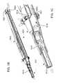
- FIG. 1Ashows a suction apparatus for use with a surgical instrument.
- FIGS. 1B and 1Care cutaway views of the suction apparatus shown in FIG. 1A .
- FIGS. 2A-2Eillustrate one-handed operation for controlled extension of the extendable suction tube of the extendable suction attachment.
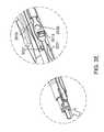
- FIGS. 3A-3Eare detailed views illustrating operation of suction control ports.
- FIGS. 4A-4Care detailed views illustrating a plurality of differently shaped suction tip extension members and a plurality of differently shaped electrocautery electrodes.
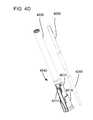
- FIGS. 4D-4Eare detailed views illustrating an electrode extender, a plurality of differently shaped suction tip extension members and a plurality of differently shaped electrocautery electrodes.
- FIG. 5Ais a detailed cutaway view of one embodiment of the smoke intake manifold of the suction apparatus.
- FIGS. 5B-5Dare end views showing controllable operation of the smoke intake manifold of the suction apparatus.
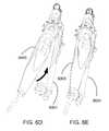
- FIGS. 6A-6Eillustrate engagement and releasable securing of the suction attachment with the surgical instrument.
- FIG. 7shows an alternative embodiment of the suction attachment.
- FIG. 8shows another alternative embodiment, wherein suction capability is made integral with the surgical instrument.
- FIG. 9is a flow diagram of a process for using a surgical instrument that may generate smoke.
- FIG. 10is a flow diagram of a process for using an electrosurgical pencil that alternatively employs one of a plurality of differently shaped electrocautery electrodes.
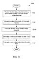
- FIG. 11is a flow diagram of another process for using a surgical instrument that may generate smoke.
- FIG. 12is a flow diagram of another process for using an electrosurgical pencil.
- a suction apparatusevacuates the surgical smoke.
- the suction apparatusmay be arranged adjacent to an electrocautery electrode, which may generate smoke during operation, for evacuating smoke from a surgical site.
- FIG. 1Ashows a suction apparatus 1001 for use with a surgical instrument 1003 that may generate smoke.
- the suction apparatus 1001may comprise an extendable suction attachment 1001 for one handed operation with the surgical instrument 1003 .
- the suction apparatus 1001e.g. extendable suction attachment 1001
- the suction apparatus 1001 and its related componentsmay be formed from one or more suitable materials, for example, comprising medical grade plastic.
- the suction apparatus 1001 (e.g. extendable suction attachment 1001 ) and its related componentsmay be formed by suitable techniques, for example, by molding.
- the surgical instrument 1003may comprise an electrosurgical pencil 1003 , which may have an electrocautery electrode 1005 , a handpiece 1007 , and at least one switch 1009 for activating the electrocautery electrode 1005 .
- the electrocautery electrode 1005may be coupled through switch 1009 and through a high voltage cable to a radio frequency generator 1010 , which is suitably selected of electrosurgery.
- the inventionis not strictly limited to use with the electrotrosurgical pencil 1003 and with the electrocautery electrode 1005 shown in the figures.
- the surgical instrumentmay be other than the electrosurgical device.
- the surgical instrumentmay be a laser surgical device or a radiosurgical device, which may generate smoke or other vaporous waste.
- the extendable suction attachment 1001may comprise an extendable suction tube 1011 having proximal and distal ends.
- the extendable suction tube 1011may have a suction tube lumen 1012 arranged for receiving the electrocautery electrode 1005 of the electrosurgical pencil 1003 .
- the suction apparatus 1001may further comprise an extension control 1013 coupled with the extendable suction tube for controlling extendable movement of the distal end of the extendable suction tube 1011 over the electrocautery electrode 1005 .
- an extension control 1013coupled with the extendable suction tube for controlling extendable movement of the distal end of the extendable suction tube 1011 over the electrocautery electrode 1005 .
- the extension control 1013may comprise a thumb control 1013 coupled with the extendable suction tube 1011 for controlling extendable movement of the distal end of the extendable suction tube 1011 over the electrocautery electrode 1005 .
- Switch 1009may comprise a finger switch 1009 disposed on an outer surface of the handpiece 1007 of the electrosurgical pencil 1003 ; and the thumb control 1013 may be arranged as shown in FIG. 1A for one handed operation of the extendable suction attachment 1001 with the finger switch 1009 of the electrosurgical pencil.
- the extendable suction attachment 1001may further comprise a smoke intake manifold 1014 having a smoke intake lumen, wherein the smoke intake manifold 1014 may be adapted for arrangement adjacent to the surgical instrument 1003 and/or the electrocautery electrode 1005 .
- the smoke intake manifold 1014may be arranged proximate to the electrocautery electrode 1005 when the electrocautery electrode 1005 is received by the suction tube lumen 1012 of the extendable suction tube 1011 .
- the surgical instrumentmay be other than the electrosurgical device 1003 shown in FIG. 1A .
- the surgical instrumentmay be the laser surgical device or the radiosurgical device. In such cases, the smoke intake manifold may be adapted for arrangement adjacent to the laser surgical device or the radiosurgical device.
- the smoke intake manifold 1014may have an outer perimeter, and a plurality of suction intake ports 1017 may be arranged about the outer perimeter of the smoke intake manifold 1014 for evacuating smoke that may be generated by the surgical instrument 1003 .
- the extendable suction attachment 1001may further comprise an attachment housing 1019 fluidly coupled with the smoke intake manifold 1014 and with the proximal end of the extendable suction tube 1011 .
- the extendable suction tube 1011may be adapted for evacuating and transporting liquid (or liquid intermixed with some smoke) during surgical operations with the surgical instrument 1003 , while the smoke intake manifold 1014 may be adapted for evacuating and transporting smoke during surgical operations.
- the suction apparatus 1001may further comprise and an isolation member disposed within the attachment housing 1019 for isolating the extendable suction tube 1011 and smoke intake manifold 1014 from fluid intercommunication within the attachment housing 1019 .
- the isolation member disposed within the attachment housing 1019may substantially isolate liquid evacuated by the extendable suction tube 1011 from smoke evacuated by the smoke intake manifold 1014 .
- the isolation member disposed within the attachment housing 1019may provide for substantially separate transport of the liquid and smoke, so that the liquid may be output at a liquid output port 1023 of the suction apparatus 1001 for collection at a liquid vacuum and reservoir 1025 , while the smoke may be output at a smoke output port 1027 of the suction apparatus 1001 for collection at a smoke vacuum and filter 1029 .
- suitable tubingmay be used for fluidly coupling the liquid output port 1023 of the suction apparatus 1001 with the liquid vacuum and reservoir 1025 , and for fluidly coupling the smoke output port 1027 of the suction apparatus 1001 with the smoke vacuum and filter 1029 . Since some smoke may be intermixed with the liquid, the liquid vacuum and reservoir 1025 may also include its own smoke filter.
- FIGS. 1B and 1Care cutaway views of the suction apparatus 1001 shown in FIG. 1A .
- FIG. 1Cshows a detailed cutaway view.
- the attachment housing 1019may be supportively coupled with the proximal end of the extendable suction tube 1011 .
- the extendable suction tube 1011may be adapted for evacuating and transporting liquid (or liquid intermixed with some smoke) during surgical operations with the surgical instrument 1003 .
- notional flat arrowheadsshow the flow of the liquid from intake at the distal end of the extendable suction tube 1011 , through the lumen 1012 of the extendable suction tube 1011 , and through a first interior chamber 1018 of the attachment housing 1019 to be output at the liquid output port 1023 of the suction apparatus 1001 .
- the smoke intake manifold 1014may be adapted for evacuating and transporting smoke during surgical operations.
- FIGS. 1B and 1Cnotional flat arrowheads show the flow of smoke from the intake manifold, through a second interior chamber 1020 of the attachment housing 1019 to be output at the smoke output port 1027 of the suction apparatus 1001 .
- the isolation member 1021is shown in FIG. 1C separating the first and second interior chambers 1018 , 1020 .
- the isolation member 1021may be disposed within the attachment housing 1019 for isolating the extendable suction tube 1011 and smoke intake manifold 1014 from fluid intercommunication within the attachment housing 1019 . As shown in FIG. 1C , the isolation member 1021 may substantially isolate liquid evacuated by the extendable suction tube 1011 from smoke evacuated by the smoke intake manifold 1014 . The isolation member 1021 may coupled with the extendable suction tube 1011 and the smoke intake manifold 1014 for substantially isolating the extendable suction tube 1011 and smoke intake manifold 1014 from fluid intercommunication.
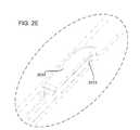
- FIGS. 2A-2Eillustrate one-handed operation for controlled extension of the extendable suction tube 2011 of the extendable suction attachment 2001 .
- an operators hand, and in particular movement of the operator's thumbis shown in dashed or phantom line.
- Extension control 2013(for example thumb control 2013 ) may be slideably coupled with the attachment housing 2019 and may be coupled with the extendable suction tube 2011 for controlling extendable movement of the distal end of the extendable suction tube 2011 over the electrocautery electrode 2005 .
- the operator's thumbmay slideably move thumb control 2013 for controlling extendable movement of the distal end of the extendable suction tube 2011 over the electrocautery electrode 2005 .
- the extendable suction attachment 2001may further comprise: a first movement limiting slot 2031 coupled with the attachment housing 2019 for limiting movement of the extendable suction tube 2011 to a preselected full extent of the distal end covering the electrocautery electrode; and an opposing movement limiting slot 2033 coupled with the attachment housing for limiting movement of the extendable suction tube 2011 to a preselected retraction extent of the distal end of the extendable suction tube 2011 , so as to expose the electrocautery electrode outside 2005 of the lumen of the extendable suction tube 2011 .
- FIG. 2Ashows movement of the extendable suction tube 2011 to a position of a preselected full extent of the distal end of the extendable suction tube 2011 covering the electrocautery electrode 2005 .
- the first movement limiting slot 2031may be coupled with the attachment housing 2019 for limiting movement of the extendable suction tube 2011 (via limiting movement of the thumb control 2013 ) to the preselected full extent of the distal end covering the electrocautery electrode 2005 .
- FIG. 2Bis a detailed cutaway view showing the first movement limiting slot 2031 limiting the movement of the extendable suction tube (via limiting movement of the thumb control 2013 ) to the preselected full extent of the distal end covering the electrocautery electrode.
- FIG. 2Cshows movement of the extendable suction tube 2011 to a position of an intermediate extent of the distal end of the extendable suction tube 2011 partially retracted and partially covering the electrocautery electrode 2005 .
- FIG. 2Dshows movement of the extendable suction tube 2011 to a position of a preselected retraction extent of the distal end of the extendable suction tube 2011 , so as to expose the electrocautery electrode 2005 outside of the lumen of the extendable suction tube 2011 .
- FIG. 2Eis a detailed cutaway view showing the opposing movement limiting slot 2033 limiting the movement of the extendable suction tube (via limiting movement of the thumb control 2013 ) to the preselected retraction extent of the distal end of the extendable suction tube, so as to expose the electrocautery electrode outside of the lumen of the extendable suction tube.
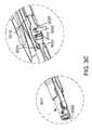
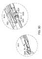
- FIGS. 3A-3Eare detailed views illustrating operation of suction control ports, which may be fluidly coupled with the proximate end of the extendable suction tube 3011 for controlling suction at the distal end of the extendable suction tube 3011 .
- a first suction control port 3035may be disposed at a location extending through the thumb control 3013 .
- a second suction control port 3037may extend through a wall of the attachment housing 3019 , wherein the second suction control port 3037 may be fluidly coupled with the proximate end of the extendable suction tube 3011 for controlling suction at the distal end of the extendable suction tube 3011 .
- the second suction control port 3037may be arranged at a location adjacent to the location of the first suction control port 3037 .
- first movement limiting slot 3031may be coupled with the attachment housing 3019 for limiting movement of the extendable suction tube 3011 to the preselected full extent of the distal end of the extendable suction tube 3011 covering the electrocautery electrode 3005 .
- first and second suction control ports 3035 , 3037may be arranged in substantial alignment as shown in FIGS. 3A-3C , when the thumb control 3013 slideably coupled with the attachment housing 3019 controls the movement of the extendable suction tube 3011 to the preselected full extent of the distal end of the suction tube 3011 covering the electrocautery electrode 3005 .
- the first suction control port 3035may be disposed at a location extending through the thumb control 3013 , and substantially sized for variable sealing of the first suction control port by an operator's thumb in one handed operation of the extended suction attachment with the electrosurgical pencil.
- the operator's thumbis drawn in dashed of phantom line.
- Full sealing by the operator's thumb in FIG. 3Ais shown corresponding to full suction at the distal end of the suction tube 3011 , wherein such full suction at the distal end of the suction tube 3011 is depicted in FIG. 3A by a notional flat arrow head.
- Partial sealing by the operator's thumb in FIG. 3Bis shown corresponding to diminished suction at the distal end of the suction tube 3011 , wherein such diminished suction at the distal end of the suction tube 3011 is depicted in FIG. 3B by a notional flat arrow head having a reduced size.
- Parasitic control suctionmay be admitted to the control ports 3035 , 3037 by the partial sealing by the operator's thumb in FIG. 3B , wherein such parasitic control suction is depicted in FIG. 3B by another notional flat arrow head having the reduced size.
- FIG. 3CNo sealing of control ports 3035 , 3037 by any operator's thumb is shown in FIG. 3C . Accordingly, substantially no suction is shown in FIG. 3C at the distal end of the suction tube 3011 , and full parasitic control suction may be admitted to the control ports 3035 , 3037 , wherein such full parasitic control suction is depicted in FIG. 3C by a full sized notional flat arrow head at the control ports 3035 , 3037 .
- FIGS. 3A-3Cwhich show that the first and second suction control ports 3035 , 3037 may be in substantial alignment when the thumb control 3013 slideably coupled with the attachment housing 3019 controls the movement of the extendable suction tube 3011 to the preselected full extent of the distal end of the suction tube 3011 covering the electrocautery electrode 3005 ; as shown in FIGS. 3D-3E variable mis-alignment the first and second control ports 3035 , 3037 may provide variable sealing of the control ports 3035 for controlling suction at the distal end of suction tube 3011 .
- FIG. 3D-3Evariable mis-alignment the first and second control ports 3035 , 3037 may provide variable sealing of the control ports 3035 for controlling suction at the distal end of suction tube 3011 .
- FIG. 3Dshows the first and second suction control ports 3035 , 3037 in substantial mis-alignment when the thumb control 3013 slideably coupled with the attachment housing 3019 controls the movement of the extendable suction tube 3011 to the position of intermediate extent of the distal end of the extendable suction tube 3011 partially retracted and partially covering the electrocautery electrode 3005 .
- Partial sealing by partial or intermediate mis-alignment of the first and second control ports 3035 , 3037 in FIG. 3Dis shown as corresponding to diminished suction at the distal end of the suction tube 3011 , wherein such diminished suction at the distal end of the suction tube 3011 is depicted in FIG. 3D by a notional flat arrow head having a reduced size.
- Some parasitic control suctionmay be admitted to the control ports 3035 , 3037 by the partial sealing by partial or intermediate mis-alignment of the first and second control ports 3035 , 3037 , wherein such parasitic control suction is depicted in FIG. 3D by another notional flat arrow head having the reduced size.
- FIG. 3Eshows movement of the extendable suction tube 3011 to the position of preselected retraction extent of the distal end of the extendable suction tube 3011 , so as to expose the electrocautery electrode 3005 outside of the lumen of the extendable suction tube 3011 .
- the second suction control portmay no longer be visible through the first suction control port 3035 .
- a substantially full sealing by the substantially full mis-alignment of the first and second control ports in FIG. 3Eis shown as corresponding to substantially full suction at the distal end of the suction tube 3011 , wherein such substantially full suction at the distal end of the suction tube 3011 is depicted in FIG. 3E by the full size notional flat arrow head.
- FIGS. 4A-4Care detailed views illustrating a plurality of differently shaped suction tip extension members and a plurality of differently shaped electrocautery electrodes.
- the suction apparatusmay be used with the electrosurgical pencil, which may alternatively employ one of the plurality of differently shaped electrocautery electrodes 4040 , 4042 .
- extendable suction tube 4043may comprise main suction tube 4011 alternatively coupled with at least one of a plurality of differently shaped suction tip extension members 4039 , 4041 , wherein each of the differently shaped suction tip extension members 4039 , 4041 is shaped for receiving a corresponding respective one of the differently shaped electrocautery electrodes 4040 , 4042 .
- Attachment housing 4019may be supportively coupled with the extendable suction tube 4043 .
- Extension control 4013may be slideably coupled with the housing 4019 and coupled with extendable suction tube 4043 for controlling extendable movement. Accordingly, extendable movement of at least one of the differently shaped suction tip extension members 4039 , 4041 may be controlled over the corresponding respective one of the differently shaped electrocautery electrodes 4040 , 4042 .
- first movement limiting slotmay be coupled with the housing for limiting movement of extendable suction tube to the preselected full extent over the electrocautery electrode.
- the opposing movement limiting slotmay be coupled with the housing for limiting movement of the extendable suction tube to the preselected retraction extent over the electrocautery electrode, so as to expose the electrocautery electrode outside of the extendable suction tube.
- first movement limiting slotmay be coupled with the housing for limiting movement of at least one of the differently shaped suction tip extension members 4039 , 4041 to a preselected full extent over the corresponding respective one of the differently shaped electrocautery electrodes 4040 , 4042 .
- Opposing movement limiting slotmay be coupled with the housing for limiting movement of at least one of the differently shaped suction tip extension members 4039 to the preselected retraction extent over the corresponding respective one of the differently shaped electrocautery electrodes 4040 , 4042 , so as to expose the corresponding respective one of the differently shaped electrocautery electrodes 4040 , 402 outside of at least one of the differently shaped suction tip extension members 4039 , 4041 .
- each of the suction tip extension members 4039 , 4041may have a respective one of a plurality of differently shaped lumens, so that each of the lumens may be shaped for receiving the corresponding respective one of the differently shaped electrocautery electrodes 4040 , 4042 .
- Each of the suction tip extension members 4039 , 4041may have a respective one of a plurality of different longitudinal dimensions L 1 , L 2 , so that each of the longitudinal dimensions L 1 , L 2 of the suction tip extension members may be selected for receiving the corresponding respective one of the differently shaped electrocautery electrodes 4040 , 4042 .
- Each of the suction tip extension members 4039 , 4041may have a respective one of a plurality of different radial dimensions R 1 , R 2 , so that each of the radial dimensions R 1 , R 2 of the suction tip extension members 4039 , 4041 may be selected for receiving the corresponding respective one of the differently shaped electrocautery electrodes 4040 , 4042 .
- a first suction tip extension member 4039may have a first longitudinal dimension L 1 selected for receiving a blade shaped electrocautery electrode 4040 having a corresponding longitudinal dimension L 1 .
- the first suction tip extension member 4039may have a first radial dimension R 1 selected for receiving the blade shaped electrocautery electrode 4040 having a corresponding radial dimension R 1 .
- a second suction tip extension member 4041may have a longitudinal dimension L 2 selected for receiving a hoop shaped electrocautery electrode 4042 having corresponding longitudinal dimension L 2 .
- the second suction tip extension member 4041may have a radial dimension R 2 selected for receiving the hoop shaped electrocautery electrode 4042 having corresponding radial dimension R 2 .
- Comparison of FIGS. 4B and 4Cillustrates movement between alternative extension and retraction positions of the extendable suction tube 4043 over the hoop shaped electrocautery electrode 4042 .
- FIGS. 4D-4Eare detailed views illustrating an electrode extender 4045 , a plurality of differently shaped suction tip extension members 4039 , 4041 and a plurality of differently shaped electrocautery electrodes 4050 , 4052 .
- the suction apparatusmay be adapted for receiving at least one electrode extender 4045 for alternatively coupling with one of the plurality of differently shaped electrocautery electrodes 4050 , 4052 .
- At least one of the suction tip extension members 4039 , 4041may be adapted for receiving at least one electrode extender 4045 for alternatively coupling with one of the plurality of differently shaped electrocautery electrodes 4050 , 4052 .
- FIG. 5Ais a detailed cutaway view of one embodiment of the smoke intake manifold of the suction apparatus.
- the smoke intake manifoldmay comprise a ring manifold 5014 , which may have a lumen 5055 extending substantially around the ring manifold 5014 .
- the ring manifold 5014may have an inner perimeter 5057 for receiving the surgical instrument, and may have an outer perimeter 5058 .
- a plurality of suction intake ports 5017may be arranged about the outer perimeter 5058 of the ring manifold 5014 for evacuating smoke that may be generated by the surgical instrument.
- notional flat arrowheadsshow smoke taken into the lumen 5055 of the ring manifold 5014 through the suction intake ports. As shown by notional flat arrowheads in FIG. 5A , the smoke may move through the lumen 5055 of the ring manifold 5014 to be collected in one of the interior chambers of the attachment housing.
- FIGS. 5B-5Dare end views showing controllable operation of the smoke intake manifold (e.g. ring manifold 5014 ) of the suction apparatus.
- the suction apparatusmay further comprise a rotatable suction control band 5061 , which may substantially encircle the suction intake ports 5017 of the outer perimeter of the ring manifold 5014 for variably sealing the suction intake ports 5017 of the ring manifold 5014 , so as to variably control suction for evacuating smoke that may be generated by the surgical instrument.
- the rotatable suction control band 5061may have a plurality of suction control ports 5063 penetrating the rotatable suction control band 5061 .
- Each of the suction control ports 5063may be arranged adjacent to a respective one of the suction intake ports 5017 for variable alignment therewith, so as to variably control suction for evacuating smoke that may be generated by the surgical instrument.
- the rotatable suction control band 5061may be rotatably positioned for substantially sealing the suction intake ports of the ring manifold 5014 .
- the plurality of suction control ports 5063may be fully mis-aligned with the suction intake ports, so that the suction intake ports are not visible.
- the rotatable suction control band 5061may be rotatably positioned for partial sealing of the suction intake ports 5017 of the ring manifold 5014 , so as to provide for partial admittance of smoke into the suction intake ports 5017 of the ring manifold 5014 .
- small flat notional arrowheadsillustrate the partial admittance of smoke.
- the plurality of suction control ports 5063may be partially aligned and may be partially mis-aligned with the suction intake ports 5017 , so that the suction intake ports 5017 are partially visible.
- the rotatable suction control band 5061may be rotatably positioned for substantially open admittance of smoke at the suction intake ports 5017 of the ring manifold 5014 .
- large flat notional arrowheadsillustrate the substantially open admittance of smoke.
- the plurality of suction control ports 5063may be fully aligned with the suction intake ports 5017 , so that the suction intake ports 5017 are fully visible.
- FIGS. 6A-6Eillustrate engagement and releasable securing of the suction attachment 6001 with the surgical instrument 6003 (e.g. electrosurgical pencil 6003 ).
- the surgical instrument 6003e.g. electrosurgical pencil 6003
- FIG. 6Aillustrates the suction attachment releasably secured to the surgical instrument 6003
- FIG. 6Bshow partial separation of the suction attachment 6001 and the surgical instrument 6003 , as the surgical instrument 6003 is lifted back and away from the suction attachment 6001 .
- FIG. 6Cshows full separation of the suction attachment 6001 from the surgical instrument 6003 .
- the suction attachment 6001may be separable from the surgical instrument 6003 .
- the suction attachmentmay be disposable.
- a first engagement member 6065may be visible. As shown in FIG. 6C , the first engagement member 6065 may be coupled at a location within a central bore of the suction attachment 6001 for receiving and releasably securing the surgical instrument.
- the first engagement member 6065may comprise an o-ring.
- the first engagement member 6065may comprise an expanded foam.
- the first engagement member 6065may comprise an adhesive tape.
- the first engagement member 6065may comprise a thermoelastic polymer gasket.
- an opposing engagement member 6067may be coupled at a distal location from first engagement member 6065 , for receiving and releasably securing the surgical instrument.
- the opposing engagement member 6067may comprise a U shaped clip.
- the opposing engagement membermay be made integral with the attachment housing of the suction attachment 6001 .
- the engagement members of the suction attachment 6001may be alternatively arrangeable with the electrosurgical pencil for ambidextrous one handed operation of the thumb control of the suction attachment 6001 and the finger switch of the surgical instrument 6003 .
- releasable securing of the suction attachment 6001 with the surgical instrument 6003 as shown in FIGS. 6 A- 6 Bmay be suitable for right handed operation
- alternative arrangementmay be employed for left handed operation.
- FIGS. 6D-6Eshow such alternative arrangement for releasable securing of the suction attachment 6001 with the surgical instrument 6003 , which may be suitable for left handed operation.
- FIG. 7shows an alternative embodiment of the suction attachment 7001 for the surgical instrument 7003 .
- the isolation memberdisposed within the attachment housing for substantially separating transport of liquid and smoke, so that the liquid may be output at the liquid output port while the smoke may be output at a smoke output port.
- a single output port 7069may be provided, instead of two ports as discussed previously herein.
- the isolation membermay be omitted.
- FIG. 8shows another alternative embodiment, wherein suction capability is made integral with the surgical instrument 8001 .
- a single output port 8069may be provided, instead of two ports as discussed previously herein.
- features of the attachment housing discussed previously hereinneed not be separate from the surgical instrument housing, and may be made integral with the surgical instrument.
- the engagement members discussed previously hereinmay be omitted.
- FIG. 9is a flow diagram of a process 900 for using a surgical instrument that may generate smoke.
- Such process 900may begin with receiving 902 the surgical instrument within an inner perimeter of a ring manifold, wherein the ring manifold has a plurality of suction intake ports disposed about an outer perimeter of the ring manifold.
- the process 900may continue with releasably securing 904 the ring manifold to the surgical instrument.
- the process 900may continue with activating 906 the surgical instrument so as to generate smoke.
- the process 900may continue with evacuating 908 the smoke using the suction intake ports of the ring manifold.
- the process 900may continue with separating 910 the ring manifold from the electrosurgical pencil.
- the ring manifoldmay be disposable and separating 910 may further comprise disposing of the ring manifold. Once the ring manifold has been separated from the surgical instrument, the process 900 may end.
- FIG. 10is a flow diagram of a process 1000 for using an electrosurgical pencil that alternatively employs one of a plurality of differently shaped electrocautery electrodes.
- the process 1000may begin with receiving 1002 one of the differently shaped electrocautery electrodes in a corresponding respective one of a plurality of differently shaped suction tip extension members of an extendable suction attachment.
- the process 1000may continue with electrically activating 1004 the electrocautery electrode.
- the process 1000may continue with moveably extending 1006 one of the plurality of differently shaped suction tip extension members.
- the process 1000may continue with separating 1008 the extendable suction attachment from the electrosurgical pencil.
- the extendable suction attachmentmay be disposable and such separating 1008 may further comprising disposing of the extendable suction attachment. Once the extendable suction attachment has been separated from the electrosurgical pencil, the process 1000 may end.
- FIG. 11is a flow diagram of another process 1100 for using a surgical instrument that may generate smoke.
- the process 1100may begin with providing 1102 a suction apparatus comprising an extendable suction tube and a smoke intake manifold having a plurality of suction ports.
- the process 1100may continue with activating 1104 the surgical instrument so as to generate smoke.
- the process 1100may continue with evacuating the smoke 1106 using suction intake ports of the smoke intake manifold.
- the processmay continue with moveably extending 1108 the extendable suction tube.
- the process 1100may continue with evacuating liquid 1110 using the extendable suction tube during surgical operations with the surgical instrument.
- FIG. 12is a flow diagram of another process 1200 for using an electrosurgical pencil.
- the process 1200may begin with receiving 1202 the electrocautery electrode within a lumen of an extendable suction tube of an extendable suction attachment.
- the process 1200may continue with releasably securing 1204 the extendable suction attachment to the electrosurgical pencil.
- the process 1200may continue with electrically activating 1206 the electrocautery electrode.
- the process 1200may continue with moveably extending 1208 the extendable suction tube of the extendable suction attachment.
- the foregoingmay comprise one handed operation of the extendable suction attachment with the electrosurgical pencil.
- the process 1200may continue with separating 1210 the extendable suction attachment from the electrosurgical pencil.
- the extendable suction attachmentmay be disposable and the separating 1210 may further comprise disposing of the extendable suction attachment.
- One advantage of the inventionmay be convenience or efficiency in evacuation of smoke and/or liquid. In turn, health of doctors and other health workers may be promoted by avoiding contact with smoke, once it is evacuated. Another advantage may be flexibility in using various differently shaped electrocautery electrodes. Another advantage may be the foregoing convenience or efficiency of evacuation when using the various differently shaped electrocautery electrodes. Another advantage may be inhibiting spread of infection by separating and disposing of disposable suction attachments.
Landscapes
- Health & Medical Sciences (AREA)
- Surgery (AREA)
- Engineering & Computer Science (AREA)
- Life Sciences & Earth Sciences (AREA)
- Biomedical Technology (AREA)
- Otolaryngology (AREA)
- Nuclear Medicine, Radiotherapy & Molecular Imaging (AREA)
- Plasma & Fusion (AREA)
- Physics & Mathematics (AREA)
- Heart & Thoracic Surgery (AREA)
- Medical Informatics (AREA)
- Molecular Biology (AREA)
- Animal Behavior & Ethology (AREA)
- General Health & Medical Sciences (AREA)
- Public Health (AREA)
- Veterinary Medicine (AREA)
- Surgical Instruments (AREA)
Abstract
Description
Claims (18)
Priority Applications (8)
| Application Number | Priority Date | Filing Date | Title |
|---|---|---|---|
| US13/021,515US8932286B2 (en) | 2011-02-04 | 2011-02-04 | Apparatus and method for electrosurgical suction |
| PCT/US2012/023673WO2012106543A1 (en) | 2011-02-04 | 2012-02-02 | Apparatus and method for electrosurgical suction |
| US14/555,392US9877773B2 (en) | 2011-02-04 | 2014-11-26 | Apparatus and method for electrosurgical suction with separate flow channels |
| US14/555,335US9763729B2 (en) | 2011-02-04 | 2014-11-26 | Apparatus and method for electrosurgical suction with suction band and replaceable tips |
| US14/561,054US9877774B2 (en) | 2011-02-04 | 2014-12-04 | Apparatus and method for electrosurgical suction with finger actuated suction control |
| US14/561,078US9867653B2 (en) | 2011-02-04 | 2014-12-04 | Apparatus and method for electrosurgical suction with dual function control |
| US15/815,789US10925660B2 (en) | 2011-02-04 | 2017-11-17 | Apparatus and method for electrosurgical suction with dual function control |
| US17/158,142US12419680B2 (en) | 2011-02-04 | 2021-01-26 | Elongated suction attachment for use with a surgical instrument that may generate smoke |
Applications Claiming Priority (1)
| Application Number | Priority Date | Filing Date | Title |
|---|---|---|---|
| US13/021,515US8932286B2 (en) | 2011-02-04 | 2011-02-04 | Apparatus and method for electrosurgical suction |
Related Child Applications (4)
| Application Number | Title | Priority Date | Filing Date |
|---|---|---|---|
| US14/555,392ContinuationUS9877773B2 (en) | 2011-02-04 | 2014-11-26 | Apparatus and method for electrosurgical suction with separate flow channels |
| US14/555,335ContinuationUS9763729B2 (en) | 2011-02-04 | 2014-11-26 | Apparatus and method for electrosurgical suction with suction band and replaceable tips |
| US14/561,078ContinuationUS9867653B2 (en) | 2011-02-04 | 2014-12-04 | Apparatus and method for electrosurgical suction with dual function control |
| US14/561,054ContinuationUS9877774B2 (en) | 2011-02-04 | 2014-12-04 | Apparatus and method for electrosurgical suction with finger actuated suction control |
Publications (2)
| Publication Number | Publication Date |
|---|---|
| US20120203165A1 US20120203165A1 (en) | 2012-08-09 |
| US8932286B2true US8932286B2 (en) | 2015-01-13 |
Family
ID=46601127
Family Applications (7)
| Application Number | Title | Priority Date | Filing Date |
|---|---|---|---|
| US13/021,515Active2033-07-12US8932286B2 (en) | 2011-02-04 | 2011-02-04 | Apparatus and method for electrosurgical suction |
| US14/555,392Active2032-01-09US9877773B2 (en) | 2011-02-04 | 2014-11-26 | Apparatus and method for electrosurgical suction with separate flow channels |
| US14/555,335Active2032-04-25US9763729B2 (en) | 2011-02-04 | 2014-11-26 | Apparatus and method for electrosurgical suction with suction band and replaceable tips |
| US14/561,054Active2032-02-10US9877774B2 (en) | 2011-02-04 | 2014-12-04 | Apparatus and method for electrosurgical suction with finger actuated suction control |
| US14/561,078Active2032-03-18US9867653B2 (en) | 2011-02-04 | 2014-12-04 | Apparatus and method for electrosurgical suction with dual function control |
| US15/815,789Active2032-10-09US10925660B2 (en) | 2011-02-04 | 2017-11-17 | Apparatus and method for electrosurgical suction with dual function control |
| US17/158,142Active2032-04-01US12419680B2 (en) | 2011-02-04 | 2021-01-26 | Elongated suction attachment for use with a surgical instrument that may generate smoke |
Family Applications After (6)
| Application Number | Title | Priority Date | Filing Date |
|---|---|---|---|
| US14/555,392Active2032-01-09US9877773B2 (en) | 2011-02-04 | 2014-11-26 | Apparatus and method for electrosurgical suction with separate flow channels |
| US14/555,335Active2032-04-25US9763729B2 (en) | 2011-02-04 | 2014-11-26 | Apparatus and method for electrosurgical suction with suction band and replaceable tips |
| US14/561,054Active2032-02-10US9877774B2 (en) | 2011-02-04 | 2014-12-04 | Apparatus and method for electrosurgical suction with finger actuated suction control |
| US14/561,078Active2032-03-18US9867653B2 (en) | 2011-02-04 | 2014-12-04 | Apparatus and method for electrosurgical suction with dual function control |
| US15/815,789Active2032-10-09US10925660B2 (en) | 2011-02-04 | 2017-11-17 | Apparatus and method for electrosurgical suction with dual function control |
| US17/158,142Active2032-04-01US12419680B2 (en) | 2011-02-04 | 2021-01-26 | Elongated suction attachment for use with a surgical instrument that may generate smoke |
Country Status (2)
| Country | Link |
|---|---|
| US (7) | US8932286B2 (en) |
| WO (1) | WO2012106543A1 (en) |
Cited By (18)
| Publication number | Priority date | Publication date | Assignee | Title |
|---|---|---|---|---|
| US9486562B2 (en) | 2014-10-24 | 2016-11-08 | Integrated Surgical, Llc | Suction device for surgical instruments |
| US20170143938A1 (en)* | 2015-11-23 | 2017-05-25 | Mivi Neuroscience, Inc. | Catheter systems for applying effective suction in remote vessels and thrombectomy procedures facilitated by catheter systems |
| US9820761B2 (en) | 2014-03-21 | 2017-11-21 | Route 92 Medical, Inc. | Rapid aspiration thrombectomy system and method |
| US10213582B2 (en) | 2013-12-23 | 2019-02-26 | Route 92 Medical, Inc. | Methods and systems for treatment of acute ischemic stroke |
| US10456555B2 (en) | 2015-02-04 | 2019-10-29 | Route 92 Medical, Inc. | Rapid aspiration thrombectomy system and method |
| US10478535B2 (en) | 2017-05-24 | 2019-11-19 | Mivi Neuroscience, Inc. | Suction catheter systems for applying effective aspiration in remote vessels, especially cerebral arteries |
| US10821212B2 (en) | 2015-07-13 | 2020-11-03 | Conmed Corporation | Surgical suction device that uses positive pressure gas |
| US10926007B2 (en) | 2015-07-13 | 2021-02-23 | Conmed Corporation | Surgical suction device that uses positive pressure gas |
| US11020133B2 (en) | 2017-01-10 | 2021-06-01 | Route 92 Medical, Inc. | Aspiration catheter systems and methods of use |
| US11065019B1 (en) | 2015-02-04 | 2021-07-20 | Route 92 Medical, Inc. | Aspiration catheter systems and methods of use |
| US11224449B2 (en) | 2015-07-24 | 2022-01-18 | Route 92 Medical, Inc. | Anchoring delivery system and methods |
| US11229770B2 (en) | 2018-05-17 | 2022-01-25 | Route 92 Medical, Inc. | Aspiration catheter systems and methods of use |
| US11234723B2 (en) | 2017-12-20 | 2022-02-01 | Mivi Neuroscience, Inc. | Suction catheter systems for applying effective aspiration in remote vessels, especially cerebral arteries |
| US11617865B2 (en) | 2020-01-24 | 2023-04-04 | Mivi Neuroscience, Inc. | Suction catheter systems with designs allowing rapid clearing of clots |
| US11871944B2 (en) | 2011-08-05 | 2024-01-16 | Route 92 Medical, Inc. | Methods and systems for treatment of acute ischemic stroke |
| US12144940B2 (en) | 2020-10-09 | 2024-11-19 | Route 92 Medical, Inc. | Aspiration catheter systems and methods of use |
| US12194247B2 (en) | 2017-01-20 | 2025-01-14 | Route 92 Medical, Inc. | Single operator intracranial medical device delivery systems and methods of use |
| US12262911B2 (en) | 2011-08-05 | 2025-04-01 | Route 92 Medical, Inc. | Methods and systems for treatment of acute ischemic stroke |
Families Citing this family (17)
| Publication number | Priority date | Publication date | Assignee | Title |
|---|---|---|---|---|
| US9737289B2 (en)* | 2010-10-29 | 2017-08-22 | Vectec S.A. | Single use, disposable, tissue suspender device |
| US20150335376A1 (en)* | 2014-05-21 | 2015-11-26 | Covidien Lp | Multipurpose electrosurgical instrument with telescoping aspiration cannula |
| USD803396S1 (en)* | 2015-12-10 | 2017-11-21 | Ethicon Llc | Handle for an endoscopic surgical instrument |
| US10420600B2 (en)* | 2016-02-02 | 2019-09-24 | Arthrex, Inc. | Ablation device with variable aspiration control system |
| US11617611B2 (en)* | 2016-06-17 | 2023-04-04 | Megadayne Medical Products, Inc. | Hand-held instrument with dual zone fluid removal |
| USD865964S1 (en) | 2017-01-05 | 2019-11-05 | Ethicon Llc | Handle for electrosurgical instrument |
| US10765472B2 (en)* | 2017-05-16 | 2020-09-08 | Megadyne Medical Products, Inc. | Electrosurgical instrument extension attachment |
| CN107999986B (en)* | 2017-12-14 | 2020-07-28 | 荣佳(惠州)医疗器械制造有限公司 | Electrotome pen welding machine and working method thereof |
| US11213341B2 (en) | 2018-08-13 | 2022-01-04 | Jgmg Bengochea, Llc | Bovie adapter for rotational control and fixation |
| USD895112S1 (en) | 2018-11-15 | 2020-09-01 | Ethicon Llc | Laparoscopic bipolar electrosurgical device |
| WO2020106993A1 (en) | 2018-11-21 | 2020-05-28 | Buffalo Filter Llc | Filtering method and apparatus |
| US10716642B1 (en)* | 2019-07-23 | 2020-07-21 | Pathy Medical, Llc | Lighting device for handheld surgical instrument with smoke evacuation system |
| CN110353801A (en)* | 2019-07-23 | 2019-10-22 | 郑州大学第三附属医院(河南省妇幼保健院) | A kind of Multifunctional electrotome and its fume removal system suitable for performing the operation |
| US20230200885A1 (en)* | 2020-06-15 | 2023-06-29 | Covidien Lp | Electrosurgical pencil with blowing and suction |
| CN112022329B (en)* | 2020-08-20 | 2021-07-23 | 温州医科大学附属第一医院 | A negative pressure suction electric knife |
| US20220117646A1 (en)* | 2020-10-16 | 2022-04-21 | Pathy Medical, Llc | Telescoping smoke evacuation device for use with handheld surgical instrument |
| EP3984482B1 (en)* | 2020-10-19 | 2025-04-23 | Erbe Elektromedizin GmbH | Device for fixing a light holding device to a surgical instrument |
Citations (70)
| Publication number | Priority date | Publication date | Assignee | Title |
|---|---|---|---|---|
| US3974833A (en) | 1973-03-19 | 1976-08-17 | Durden Iii John G | Disposable electrosurgical cautery having optional suction control feature |
| USD249549S (en) | 1976-10-22 | 1978-09-19 | Aspen Laboratories, Inc. | Electrosurgical handle |
| USD253247S (en) | 1978-03-20 | 1979-10-23 | Gill Earnest T | Electrical surgical probe |
| US4347842A (en) | 1980-02-15 | 1982-09-07 | Mark Beale | Disposable electrical surgical suction tube and instrument |
| USD270372S (en) | 1979-11-21 | 1983-08-30 | C. R. Bard, Inc. | Electro-surgical scalpel |
| US4553957A (en) | 1983-05-03 | 1985-11-19 | Alcon Laboratories, Inc. | Irrigation/aspiration handpiece |
| US4562838A (en) | 1981-01-23 | 1986-01-07 | Walker William S | Electrosurgery instrument |
| USD287879S (en) | 1984-09-10 | 1987-01-20 | Valleylab, Inc. | Electrosurgical handle |
| US4719914A (en) | 1986-12-24 | 1988-01-19 | Johnson Gerald W | Electrosurgical instrument |
| USD301739S (en) | 1986-10-15 | 1989-06-20 | Mdt Corporation | Electrosurgical pencil |
| US4919129A (en) | 1987-11-30 | 1990-04-24 | Celebration Medical Products, Inc. | Extendable electrocautery surgery apparatus and method |
| US4943290A (en) | 1987-06-23 | 1990-07-24 | Concept Inc. | Electrolyte purging electrode tip |
| US5055100A (en) | 1989-06-19 | 1991-10-08 | Eugene Olsen | Suction attachment for electrosurgical instruments or the like |
| US5071418A (en) | 1990-05-16 | 1991-12-10 | Joseph Rosenbaum | Electrocautery surgical scalpel |
| US5085657A (en) | 1983-03-14 | 1992-02-04 | Ben Simhon Haim | Electrosurgical instrument |
| US5133714A (en) | 1991-05-06 | 1992-07-28 | Kirwan Surgical Products, Inc. | Electrosurgical suction coagulator |
| USD330253S (en) | 1990-10-04 | 1992-10-13 | Birtcher Medical Systems, Inc. | Electrosurgical handpiece |
| US5154709A (en) | 1990-09-04 | 1992-10-13 | Johnson Gerald W | Vacuum hood attachment for electrosurgical instruments |
| US5181916A (en) | 1991-04-26 | 1993-01-26 | Sorenson Laboratories, Inc. | Surgical probe and smoke eliminator |
| US5192267A (en) | 1989-01-23 | 1993-03-09 | Nadiv Shapira | Vortex smoke remover for electrosurgical devices |
| US5224944A (en) | 1991-01-07 | 1993-07-06 | Elliott Martin P | Aspiration tip for a cautery handpiece |
| US5234428A (en) | 1991-06-11 | 1993-08-10 | Kaufman David I | Disposable electrocautery/cutting instrument with integral continuous smoke evacuation |
| US5242442A (en) | 1991-09-18 | 1993-09-07 | Hirschfeld Jack J | Smoke aspirating electrosurgical device |
| US5244462A (en) | 1990-03-15 | 1993-09-14 | Valleylab Inc. | Electrosurgical apparatus |
| US5246440A (en) | 1990-09-13 | 1993-09-21 | Noord Andrew J Van | Electrosurgical knife |
| US5254117A (en)* | 1992-03-17 | 1993-10-19 | Alton Dean Medical | Multi-functional endoscopic probe apparatus |
| US5269781A (en) | 1992-06-10 | 1993-12-14 | Hewell Iii Todd S | Suction-assisted electrocautery unit |
| US5318565A (en) | 1992-11-12 | 1994-06-07 | Daniel B. Kuriloff | Suction cautery dissector |
| USD351227S (en) | 1993-02-09 | 1994-10-04 | Alcon Laboratories, Inc. | Surgical handpiece shell |
| US5360427A (en) | 1992-12-18 | 1994-11-01 | Heshmat Majlessi | Retractable electro-suction device |
| US5395312A (en) | 1991-10-18 | 1995-03-07 | Desai; Ashvin | Surgical tool |
| US5413575A (en) | 1994-04-19 | 1995-05-09 | Innovative Medical Technologies, Ltd. | Multifunction electrocautery tool |
| US5431650A (en) | 1992-12-11 | 1995-07-11 | Cosmescu; Ioan | Vortex hand piece shroud for automatic smoke evacuator system for a surgical laser apparatus and method therefor |
| US5451223A (en) | 1983-03-14 | 1995-09-19 | Ben-Simhon; Haim | Electrosurgical instrument |
| US5460602A (en) | 1989-01-23 | 1995-10-24 | Shapira; Nadiv | Smoke evacuator for smoke generating devices |
| USD370731S (en) | 1995-03-07 | 1996-06-11 | Medtronic, Inc. | Electrocautery handle |
| USD373190S (en) | 1994-10-06 | 1996-08-27 | Donaldson Company, Inc. | Smoke evacuator for an electrocautery scalpel |
| USD384148S (en) | 1996-03-18 | 1997-09-23 | Donaldson Company, Inc. | Smoke evacuator for an electrocautery scalpel |
| US5674219A (en) | 1994-10-06 | 1997-10-07 | Donaldson Company, Inc. | Electrosurgical smoke evacuator |
| US5693044A (en) | 1992-12-11 | 1997-12-02 | Cosmescu; Ioan | Telescopic surgical device and method therefor |
| USD393067S (en) | 1996-08-27 | 1998-03-31 | Valleylab Inc. | Electrosurgical pencil |
| US5800431A (en) | 1996-10-11 | 1998-09-01 | Brown; Robert H. | Electrosurgical tool with suction and cautery |
| USD399314S (en) | 1996-09-25 | 1998-10-06 | Genzyme Corporation | Suction tip for an electrocautery apparatus |
| US5830214A (en) | 1994-11-08 | 1998-11-03 | Heartport, Inc. | Fluid-evacuating electrosurgical device |
| US5836909A (en) | 1996-09-13 | 1998-11-17 | Cosmescu; Ioan | Automatic fluid control system for use in open and laparoscopic laser surgery and electrosurgery and method therefor |
| USD402030S (en) | 1997-10-29 | 1998-12-01 | Megadyne Medical Products, Inc. | Electrosurgical pencil with push button actuators |
| US5951548A (en) | 1997-02-21 | 1999-09-14 | Stephen R. DeSisto | Self-evacuating electrocautery device |
| US6047700A (en)* | 1998-03-30 | 2000-04-11 | Arthrocare Corporation | Systems and methods for electrosurgical removal of calcified deposits |
| USD426883S (en) | 1999-07-22 | 2000-06-20 | Surgiform Technology, Ltd. | Cauterization smoke evacuator |
| US6099525A (en) | 1996-10-07 | 2000-08-08 | Cosmescu; Ioan | Removable shroud for receiving a pencil used in electro-surgery |
| US6117134A (en) | 1996-02-14 | 2000-09-12 | Cunningham; James Steven | Instrument for suction electrosurgery |
| USD453222S1 (en) | 2001-04-30 | 2002-01-29 | Jon C. Garito | Electrosurgical handpiece |
| US6355034B2 (en) | 1996-09-20 | 2002-03-12 | Ioan Cosmescu | Multifunctional telescopic monopolar/bipolar surgical device and method therefor |
| US6610059B1 (en)* | 2002-02-25 | 2003-08-26 | Hs West Investments Llc | Endoscopic instruments and methods for improved bubble aspiration at a surgical site |
| US6616658B2 (en) | 2001-11-08 | 2003-09-09 | Leonard Ineson | Electrosurgical pencil |
| US6840937B2 (en)* | 2001-10-18 | 2005-01-11 | Electrosurgery Associates, Llc | Electrosurgical ablator with aspiration |
| US6855143B2 (en)* | 1997-06-13 | 2005-02-15 | Arthrocare Corporation | Electrosurgical systems and methods for recanalization of occluded body lumens |
| US20050113825A1 (en) | 1996-09-20 | 2005-05-26 | Ioan Cosmescu | Multifunctional telescopic monopolar/bipolar surgical device and method therefore |
| US20050283149A1 (en)* | 2004-06-08 | 2005-12-22 | Thorne Jonathan O | Electrosurgical cutting instrument |
| US20060264928A1 (en) | 2003-11-14 | 2006-11-23 | Niels Kornerup | Length adjustable electro-surgical pencil with suction means |
| US7172592B2 (en) | 2003-09-29 | 2007-02-06 | Desisto Stephen R | Self-evacuating electrocautery device |
| US20070129722A1 (en) | 2005-12-02 | 2007-06-07 | Ioan Cosmescu | Swivel device for improved surgical smoke evacuation |
| US7241294B2 (en) | 2003-11-19 | 2007-07-10 | Sherwood Services Ag | Pistol grip electrosurgical pencil with manual aspirator/irrigator and methods of using the same |
| USD547867S1 (en) | 2006-04-17 | 2007-07-31 | Synergetics Usa, Inc. | Surgical instrument handle |
| USD547864S1 (en) | 2005-01-11 | 2007-07-31 | Karl Storz Gmbh & Co. Kg | Handle for a medical instrument |
| US7303559B2 (en) | 2003-02-19 | 2007-12-04 | Shuyou Peng | Multiplefunction surgical dissector |
| US7329253B2 (en)* | 2003-12-09 | 2008-02-12 | Rubicor Medical, Inc. | Suction sleeve and interventional devices having such a suction sleeve |
| US20090062791A1 (en) | 2007-08-30 | 2009-03-05 | Lee Alan R | Integrated smoke evacuation electrosurgical pencil and method |
| US7537594B2 (en) | 2003-05-01 | 2009-05-26 | Covidien Ag | Suction coagulator with dissecting probe |
| US20090326511A1 (en)* | 2008-05-30 | 2009-12-31 | Kalyanam Shivkumar | Method to protect the esophagus and other mediastinal structures during cardiac and thoracic interventions |
Family Cites Families (6)
| Publication number | Priority date | Publication date | Assignee | Title |
|---|---|---|---|---|
| US5063908A (en)* | 1989-06-02 | 1991-11-12 | Collins Jason H | Adapter for cervical speculum |
| US5160334A (en)* | 1991-04-30 | 1992-11-03 | Utah Medical Products, Inc. | Electrosurgical generator and suction apparatus |
| US5643304A (en)* | 1993-02-16 | 1997-07-01 | Danek Medical, Inc. | Method and apparatus for minimally invasive tissue removal |
| GB9612993D0 (en)* | 1996-06-20 | 1996-08-21 | Gyrus Medical Ltd | Electrosurgical instrument |
| US6524307B1 (en)* | 2001-10-05 | 2003-02-25 | Medtek Devices, Inc. | Smoke evacuation apparatus |
| US20030220611A1 (en)* | 2002-05-22 | 2003-11-27 | Surgimark, Inc. | Aspirator sleeve and tip |
- 2011
- 2011-02-04USUS13/021,515patent/US8932286B2/enactiveActive
- 2012
- 2012-02-02WOPCT/US2012/023673patent/WO2012106543A1/enactiveApplication Filing
- 2014
- 2014-11-26USUS14/555,392patent/US9877773B2/enactiveActive
- 2014-11-26USUS14/555,335patent/US9763729B2/enactiveActive
- 2014-12-04USUS14/561,054patent/US9877774B2/enactiveActive
- 2014-12-04USUS14/561,078patent/US9867653B2/enactiveActive
- 2017
- 2017-11-17USUS15/815,789patent/US10925660B2/enactiveActive
- 2021
- 2021-01-26USUS17/158,142patent/US12419680B2/enactiveActive
Patent Citations (74)
| Publication number | Priority date | Publication date | Assignee | Title |
|---|---|---|---|---|
| US3974833A (en) | 1973-03-19 | 1976-08-17 | Durden Iii John G | Disposable electrosurgical cautery having optional suction control feature |
| USD249549S (en) | 1976-10-22 | 1978-09-19 | Aspen Laboratories, Inc. | Electrosurgical handle |
| USD253247S (en) | 1978-03-20 | 1979-10-23 | Gill Earnest T | Electrical surgical probe |
| USD270372S (en) | 1979-11-21 | 1983-08-30 | C. R. Bard, Inc. | Electro-surgical scalpel |
| US4347842A (en) | 1980-02-15 | 1982-09-07 | Mark Beale | Disposable electrical surgical suction tube and instrument |
| US4562838A (en) | 1981-01-23 | 1986-01-07 | Walker William S | Electrosurgery instrument |
| US5085657A (en) | 1983-03-14 | 1992-02-04 | Ben Simhon Haim | Electrosurgical instrument |
| US5451223A (en) | 1983-03-14 | 1995-09-19 | Ben-Simhon; Haim | Electrosurgical instrument |
| US5451223B1 (en) | 1983-03-14 | 1998-11-03 | Ben Simhon Haim | Electrosurgical instrument |
| US4553957A (en) | 1983-05-03 | 1985-11-19 | Alcon Laboratories, Inc. | Irrigation/aspiration handpiece |
| USD287879S (en) | 1984-09-10 | 1987-01-20 | Valleylab, Inc. | Electrosurgical handle |
| USD301739S (en) | 1986-10-15 | 1989-06-20 | Mdt Corporation | Electrosurgical pencil |
| US4719914A (en) | 1986-12-24 | 1988-01-19 | Johnson Gerald W | Electrosurgical instrument |
| US4943290A (en) | 1987-06-23 | 1990-07-24 | Concept Inc. | Electrolyte purging electrode tip |
| US4919129A (en) | 1987-11-30 | 1990-04-24 | Celebration Medical Products, Inc. | Extendable electrocautery surgery apparatus and method |
| US5192267A (en) | 1989-01-23 | 1993-03-09 | Nadiv Shapira | Vortex smoke remover for electrosurgical devices |
| US5460602A (en) | 1989-01-23 | 1995-10-24 | Shapira; Nadiv | Smoke evacuator for smoke generating devices |
| US5055100A (en) | 1989-06-19 | 1991-10-08 | Eugene Olsen | Suction attachment for electrosurgical instruments or the like |
| US5244462A (en) | 1990-03-15 | 1993-09-14 | Valleylab Inc. | Electrosurgical apparatus |
| US5071418A (en) | 1990-05-16 | 1991-12-10 | Joseph Rosenbaum | Electrocautery surgical scalpel |
| US5154709A (en) | 1990-09-04 | 1992-10-13 | Johnson Gerald W | Vacuum hood attachment for electrosurgical instruments |
| US5246440A (en) | 1990-09-13 | 1993-09-21 | Noord Andrew J Van | Electrosurgical knife |
| USD330253S (en) | 1990-10-04 | 1992-10-13 | Birtcher Medical Systems, Inc. | Electrosurgical handpiece |
| US5224944A (en) | 1991-01-07 | 1993-07-06 | Elliott Martin P | Aspiration tip for a cautery handpiece |
| US5181916A (en) | 1991-04-26 | 1993-01-26 | Sorenson Laboratories, Inc. | Surgical probe and smoke eliminator |
| US5133714A (en) | 1991-05-06 | 1992-07-28 | Kirwan Surgical Products, Inc. | Electrosurgical suction coagulator |
| US5234428A (en) | 1991-06-11 | 1993-08-10 | Kaufman David I | Disposable electrocautery/cutting instrument with integral continuous smoke evacuation |
| US5242442A (en) | 1991-09-18 | 1993-09-07 | Hirschfeld Jack J | Smoke aspirating electrosurgical device |
| US5395312A (en) | 1991-10-18 | 1995-03-07 | Desai; Ashvin | Surgical tool |
| US5254117A (en)* | 1992-03-17 | 1993-10-19 | Alton Dean Medical | Multi-functional endoscopic probe apparatus |
| US5269781A (en) | 1992-06-10 | 1993-12-14 | Hewell Iii Todd S | Suction-assisted electrocautery unit |
| US5318565A (en) | 1992-11-12 | 1994-06-07 | Daniel B. Kuriloff | Suction cautery dissector |
| US6142995A (en) | 1992-12-11 | 2000-11-07 | Cosmescu; Ioan | Electro-surgical unit pencil apparatus having a removable shroud |
| US5431650A (en) | 1992-12-11 | 1995-07-11 | Cosmescu; Ioan | Vortex hand piece shroud for automatic smoke evacuator system for a surgical laser apparatus and method therefor |
| US5836944A (en) | 1992-12-11 | 1998-11-17 | Cosmescu; Ioan | Removable shroud for use with electrosurgery |
| US5693044A (en) | 1992-12-11 | 1997-12-02 | Cosmescu; Ioan | Telescopic surgical device and method therefor |
| US5360427A (en) | 1992-12-18 | 1994-11-01 | Heshmat Majlessi | Retractable electro-suction device |
| USD351227S (en) | 1993-02-09 | 1994-10-04 | Alcon Laboratories, Inc. | Surgical handpiece shell |
| US5413575A (en) | 1994-04-19 | 1995-05-09 | Innovative Medical Technologies, Ltd. | Multifunction electrocautery tool |
| US5674219A (en) | 1994-10-06 | 1997-10-07 | Donaldson Company, Inc. | Electrosurgical smoke evacuator |
| USD373190S (en) | 1994-10-06 | 1996-08-27 | Donaldson Company, Inc. | Smoke evacuator for an electrocautery scalpel |
| US5830214A (en) | 1994-11-08 | 1998-11-03 | Heartport, Inc. | Fluid-evacuating electrosurgical device |
| USD370731S (en) | 1995-03-07 | 1996-06-11 | Medtronic, Inc. | Electrocautery handle |
| US6117134A (en) | 1996-02-14 | 2000-09-12 | Cunningham; James Steven | Instrument for suction electrosurgery |
| USD384148S (en) | 1996-03-18 | 1997-09-23 | Donaldson Company, Inc. | Smoke evacuator for an electrocautery scalpel |
| USD393067S (en) | 1996-08-27 | 1998-03-31 | Valleylab Inc. | Electrosurgical pencil |
| US5836909A (en) | 1996-09-13 | 1998-11-17 | Cosmescu; Ioan | Automatic fluid control system for use in open and laparoscopic laser surgery and electrosurgery and method therefor |
| US6702812B2 (en) | 1996-09-20 | 2004-03-09 | Ioan Cosmescu | Multifunctional telescopic monopolar/bipolar surgical device and method therefor |
| US20050113825A1 (en) | 1996-09-20 | 2005-05-26 | Ioan Cosmescu | Multifunctional telescopic monopolar/bipolar surgical device and method therefore |
| US6355034B2 (en) | 1996-09-20 | 2002-03-12 | Ioan Cosmescu | Multifunctional telescopic monopolar/bipolar surgical device and method therefor |
| USD399314S (en) | 1996-09-25 | 1998-10-06 | Genzyme Corporation | Suction tip for an electrocautery apparatus |
| US6099525A (en) | 1996-10-07 | 2000-08-08 | Cosmescu; Ioan | Removable shroud for receiving a pencil used in electro-surgery |
| US5800431A (en) | 1996-10-11 | 1998-09-01 | Brown; Robert H. | Electrosurgical tool with suction and cautery |
| US5951548A (en) | 1997-02-21 | 1999-09-14 | Stephen R. DeSisto | Self-evacuating electrocautery device |
| US6855143B2 (en)* | 1997-06-13 | 2005-02-15 | Arthrocare Corporation | Electrosurgical systems and methods for recanalization of occluded body lumens |
| USD402030S (en) | 1997-10-29 | 1998-12-01 | Megadyne Medical Products, Inc. | Electrosurgical pencil with push button actuators |
| US6047700A (en)* | 1998-03-30 | 2000-04-11 | Arthrocare Corporation | Systems and methods for electrosurgical removal of calcified deposits |
| USD426883S (en) | 1999-07-22 | 2000-06-20 | Surgiform Technology, Ltd. | Cauterization smoke evacuator |
| USD453222S1 (en) | 2001-04-30 | 2002-01-29 | Jon C. Garito | Electrosurgical handpiece |
| US6840937B2 (en)* | 2001-10-18 | 2005-01-11 | Electrosurgery Associates, Llc | Electrosurgical ablator with aspiration |
| US6616658B2 (en) | 2001-11-08 | 2003-09-09 | Leonard Ineson | Electrosurgical pencil |
| US6610059B1 (en)* | 2002-02-25 | 2003-08-26 | Hs West Investments Llc | Endoscopic instruments and methods for improved bubble aspiration at a surgical site |
| US7303559B2 (en) | 2003-02-19 | 2007-12-04 | Shuyou Peng | Multiplefunction surgical dissector |
| US7537594B2 (en) | 2003-05-01 | 2009-05-26 | Covidien Ag | Suction coagulator with dissecting probe |
| US7172592B2 (en) | 2003-09-29 | 2007-02-06 | Desisto Stephen R | Self-evacuating electrocautery device |
| US20060264928A1 (en) | 2003-11-14 | 2006-11-23 | Niels Kornerup | Length adjustable electro-surgical pencil with suction means |
| US7241294B2 (en) | 2003-11-19 | 2007-07-10 | Sherwood Services Ag | Pistol grip electrosurgical pencil with manual aspirator/irrigator and methods of using the same |
| US7329253B2 (en)* | 2003-12-09 | 2008-02-12 | Rubicor Medical, Inc. | Suction sleeve and interventional devices having such a suction sleeve |
| US20050283149A1 (en)* | 2004-06-08 | 2005-12-22 | Thorne Jonathan O | Electrosurgical cutting instrument |
| USD547864S1 (en) | 2005-01-11 | 2007-07-31 | Karl Storz Gmbh & Co. Kg | Handle for a medical instrument |
| US20070129722A1 (en) | 2005-12-02 | 2007-06-07 | Ioan Cosmescu | Swivel device for improved surgical smoke evacuation |
| USD547867S1 (en) | 2006-04-17 | 2007-07-31 | Synergetics Usa, Inc. | Surgical instrument handle |
| US20090062791A1 (en) | 2007-08-30 | 2009-03-05 | Lee Alan R | Integrated smoke evacuation electrosurgical pencil and method |
| US20090326511A1 (en)* | 2008-05-30 | 2009-12-31 | Kalyanam Shivkumar | Method to protect the esophagus and other mediastinal structures during cardiac and thoracic interventions |
Non-Patent Citations (1)
| Title |
|---|
| International Search Report and Written Opinion of PCT/US2012/023673 issued Jun. 28, 2012, 8 pages. |
Cited By (58)
| Publication number | Priority date | Publication date | Assignee | Title |
|---|---|---|---|---|
| US12262911B2 (en) | 2011-08-05 | 2025-04-01 | Route 92 Medical, Inc. | Methods and systems for treatment of acute ischemic stroke |
| US12343036B2 (en) | 2011-08-05 | 2025-07-01 | Route 92 Medical, Inc. | Methods and systems for treatment of acute ischemic stroke |
| US11871944B2 (en) | 2011-08-05 | 2024-01-16 | Route 92 Medical, Inc. | Methods and systems for treatment of acute ischemic stroke |
| US11534575B2 (en) | 2013-12-23 | 2022-12-27 | Route 92 Medical, Inc. | Methods and systems for treatment of acute ischemic stroke |
| US10569049B2 (en) | 2013-12-23 | 2020-02-25 | Route 92 Medical, Inc. | Methods and systems for treatment of acute ischemic stroke |
| US12115320B2 (en) | 2013-12-23 | 2024-10-15 | Route 92 Medical, Inc. | Methods and systems for treatment of acute ischemic stroke |
| US12343480B2 (en) | 2013-12-23 | 2025-07-01 | Route 92 Medical, Inc. | Methods and systems for treatment of acute ischemic stroke |
| US11318282B2 (en) | 2013-12-23 | 2022-05-03 | Route 92 Medical, Inc. | Methods and systems for treatment of acute ischemic stroke |
| US10213582B2 (en) | 2013-12-23 | 2019-02-26 | Route 92 Medical, Inc. | Methods and systems for treatment of acute ischemic stroke |
| US10864351B2 (en) | 2013-12-23 | 2020-12-15 | Route 92 Medical, Inc. | Methods and systems for treatment of acute ischemic stroke |
| US10471233B2 (en) | 2013-12-23 | 2019-11-12 | Route 92 Medical, Inc. | Methods and systems for treatment of acute ischemic stroke |
| US9820761B2 (en) | 2014-03-21 | 2017-11-21 | Route 92 Medical, Inc. | Rapid aspiration thrombectomy system and method |
| US9750855B2 (en) | 2014-10-24 | 2017-09-05 | Conmed Corporation | Suction device for surgical instruments |
| US9486562B2 (en) | 2014-10-24 | 2016-11-08 | Integrated Surgical, Llc | Suction device for surgical instruments |
| US10034970B2 (en) | 2014-10-24 | 2018-07-31 | Conmed Corporation | Suction device for surgical instruments |
| US10022479B2 (en) | 2014-10-24 | 2018-07-17 | Conmed Corporation | Suction device for surgical instruments |
| US9867913B2 (en) | 2014-10-24 | 2018-01-16 | Conmed Corporation | Suction device for surgical instruments |
| US11305094B2 (en) | 2015-02-04 | 2022-04-19 | Route 92 Medical, Inc. | Rapid aspiration thrombectomy system and method |
| US11395903B2 (en) | 2015-02-04 | 2022-07-26 | Route 92 Medical, Inc. | Rapid aspiration thrombectomy system and method |
| US11633571B2 (en) | 2015-02-04 | 2023-04-25 | Route 92 Medical, Inc. | Rapid aspiration thrombectomy system and method |
| US10456555B2 (en) | 2015-02-04 | 2019-10-29 | Route 92 Medical, Inc. | Rapid aspiration thrombectomy system and method |
| US11793529B2 (en) | 2015-02-04 | 2023-10-24 | Route 92 Medical, Inc. | Aspiration catheter systems and methods of use |
| US11576691B2 (en) | 2015-02-04 | 2023-02-14 | Route 92 Medical, Inc. | Aspiration catheter systems and methods of use |
| US11065019B1 (en) | 2015-02-04 | 2021-07-20 | Route 92 Medical, Inc. | Aspiration catheter systems and methods of use |
| US11185664B2 (en) | 2015-02-04 | 2021-11-30 | Route 92 Medical, Inc. | Rapid aspiration thrombectomy system and method |
| US11224450B2 (en) | 2015-02-04 | 2022-01-18 | Route 92 Medical, Inc. | Aspiration catheter systems and methods of use |
| US10485952B2 (en) | 2015-02-04 | 2019-11-26 | Route 92 Medical, Inc. | Rapid aspiration thrombectomy system and method |
| US11224721B2 (en) | 2015-02-04 | 2022-01-18 | Route 92 Medical, Inc. | Rapid aspiration thrombectomy system and method |
| US11793972B2 (en) | 2015-02-04 | 2023-10-24 | Route 92 Medical, Inc. | Rapid aspiration thrombectomy system and method |
| US11806032B2 (en) | 2015-02-04 | 2023-11-07 | Route 92 Medical, Inc. | Aspiration catheter systems and methods of use |
| US11633570B2 (en) | 2015-02-04 | 2023-04-25 | Route 92 Medical, Inc. | Rapid aspiration thrombectomy system and method |
| US11383064B2 (en) | 2015-02-04 | 2022-07-12 | Route 92 Medical, Inc. | Rapid aspiration thrombectomy system and method |
| US10850012B2 (en) | 2015-07-13 | 2020-12-01 | Conmed Corporation | Surgical suction device that uses positive pressure gas |
| US10821212B2 (en) | 2015-07-13 | 2020-11-03 | Conmed Corporation | Surgical suction device that uses positive pressure gas |
| US10835648B2 (en) | 2015-07-13 | 2020-11-17 | Conmed Corporation | Surgical suction device that uses positive pressure gas |
| US10926007B2 (en) | 2015-07-13 | 2021-02-23 | Conmed Corporation | Surgical suction device that uses positive pressure gas |
| US10926008B2 (en) | 2015-07-13 | 2021-02-23 | Conmed Corporation | Surgical suction device that uses positive pressure gas |
| US10835649B2 (en) | 2015-07-13 | 2020-11-17 | Conmed Corporation | Surgical suction device that uses positive pressure gas |
| US12213688B2 (en) | 2015-07-24 | 2025-02-04 | Route 92 Medical, Inc. | Anchoring delivery system and methods |
| US11224449B2 (en) | 2015-07-24 | 2022-01-18 | Route 92 Medical, Inc. | Anchoring delivery system and methods |
| US11786699B2 (en) | 2015-11-23 | 2023-10-17 | Mivi Neuroscience, Inc. | Catheter systems for applying effective suction in remote vessels and thrombectomy procedures facilitated by catheter systems |
| US20170143938A1 (en)* | 2015-11-23 | 2017-05-25 | Mivi Neuroscience, Inc. | Catheter systems for applying effective suction in remote vessels and thrombectomy procedures facilitated by catheter systems |
| WO2017091554A1 (en)* | 2015-11-23 | 2017-06-01 | Mivi Neuroscience, Inc. | Catheter systems for applying effective suction in remote vessels and thrombectomy procedures facilitated by catheter systems |
| US10716915B2 (en)* | 2015-11-23 | 2020-07-21 | Mivi Neuroscience, Inc. | Catheter systems for applying effective suction in remote vessels and thrombectomy procedures facilitated by catheter systems |
| US11020133B2 (en) | 2017-01-10 | 2021-06-01 | Route 92 Medical, Inc. | Aspiration catheter systems and methods of use |
| US11399852B2 (en) | 2017-01-10 | 2022-08-02 | Route 92 Medical, Inc. | Aspiration catheter systems and methods of use |
| US12295595B2 (en) | 2017-01-10 | 2025-05-13 | Route 92 Medical, Inc. | Aspiration catheter systems and methods of use |
| US12194247B2 (en) | 2017-01-20 | 2025-01-14 | Route 92 Medical, Inc. | Single operator intracranial medical device delivery systems and methods of use |
| US10478535B2 (en) | 2017-05-24 | 2019-11-19 | Mivi Neuroscience, Inc. | Suction catheter systems for applying effective aspiration in remote vessels, especially cerebral arteries |
| US11771867B2 (en) | 2017-05-24 | 2023-10-03 | Mivi Neuroscience, Inc. | Suction catheter systems for applying effective aspiration in remote vessels, especially cerebral arteries |
| US12102341B2 (en) | 2017-12-20 | 2024-10-01 | Mivi Neuroscience, Inc. | Suction catheter systems for applying effective aspiration in remote vessels, especially cerebral arteries |
| US11234723B2 (en) | 2017-12-20 | 2022-02-01 | Mivi Neuroscience, Inc. | Suction catheter systems for applying effective aspiration in remote vessels, especially cerebral arteries |
| US11925770B2 (en) | 2018-05-17 | 2024-03-12 | Route 92 Medical, Inc. | Aspiration catheter systems and methods of use |
| US11229770B2 (en) | 2018-05-17 | 2022-01-25 | Route 92 Medical, Inc. | Aspiration catheter systems and methods of use |
| US11607523B2 (en) | 2018-05-17 | 2023-03-21 | Route 92 Medical, Inc. | Aspiration catheter systems and methods of use |
| US12383702B2 (en) | 2018-05-17 | 2025-08-12 | Route 92 Medical, Inc. | Aspiration catheter systems and methods of use |
| US11617865B2 (en) | 2020-01-24 | 2023-04-04 | Mivi Neuroscience, Inc. | Suction catheter systems with designs allowing rapid clearing of clots |
| US12144940B2 (en) | 2020-10-09 | 2024-11-19 | Route 92 Medical, Inc. | Aspiration catheter systems and methods of use |
Also Published As
| Publication number | Publication date |
|---|---|
| US20180153610A1 (en) | 2018-06-07 |
| US9763729B2 (en) | 2017-09-19 |
| US20210145505A1 (en) | 2021-05-20 |
| US9867653B2 (en) | 2018-01-16 |
| WO2012106543A1 (en) | 2012-08-09 |
| US20150094718A1 (en) | 2015-04-02 |
| US9877773B2 (en) | 2018-01-30 |
| US9877774B2 (en) | 2018-01-30 |
| US12419680B2 (en) | 2025-09-23 |
| US20120203165A1 (en) | 2012-08-09 |
| US20150088132A1 (en) | 2015-03-26 |
| US10925660B2 (en) | 2021-02-23 |
| US20150088134A1 (en) | 2015-03-26 |
| US20150088133A1 (en) | 2015-03-26 |
Similar Documents
| Publication | Publication Date | Title |
|---|---|---|
| US20210145505A1 (en) | Apparatus and method for electrosurgical suction with dual function control | |
| US8932292B2 (en) | Apparatus and method for electrosurgical suction | |
| US8518018B2 (en) | Apparatus and method for electrosurgical suction | |
| US8845616B2 (en) | Apparatus and method for electrosurgical suction | |
| US5300069A (en) | Electrosurgical apparatus for laparoscopic procedures and method of use | |
| US20030216730A1 (en) | Apparatus and method for resecting and removing selected body tissue from a site inside a patient | |
| AU759906B2 (en) | Multifunctional telescopic electrosurgical instrument, and method therefor | |
| EP3071130A1 (en) | Surgical instrument with active element and suction cage | |
| US20060276783A1 (en) | Multifunctional telescopic monopolar/bipolar surgical device and method thereof | |
| US20230181239A1 (en) | Surgical device and methods | |
| JPH06505654A (en) | electrosurgical device | |
| US10058375B2 (en) | Electrosurgical coagulation instrument including a suction pipe and a collapsible tip | |
| US12336751B2 (en) | Surgical device and methods | |
| US20140336634A1 (en) | Multifunctional attachment for electrocautery surgical device | |
| KR102517178B1 (en) | Biopsy kit and method of removal of a piece of target tissue | |
| US11730940B2 (en) | System, method and apparatus for providing multiple functions in a surgical procedure | |
| WO2021253184A1 (en) | Electrosurgical pencil with blowing and suction | |
| CA2707676A1 (en) | Multifunctional electrosurgical instrument, and method therefor | |
| EP3740260B1 (en) | Apparatus for flow |
Legal Events
| Date | Code | Title | Description |
|---|---|---|---|
| AS | Assignment | Owner name:DUFFIN, LAWRENCE, CALIFORNIA Free format text:ASSIGNMENT OF ASSIGNORS INTEREST;ASSIGNOR:MINSKOFF, NOAH MARK;REEL/FRAME:029784/0785 Effective date:20130127 | |
| AS | Assignment | Owner name:BREEDE, MICHAEL EDWARD, CONNECTICUT Free format text:SECURITY AGREEMENT;ASSIGNOR:TERRY, NATHAN ANDREW;REEL/FRAME:030620/0949 Effective date:20130401 | |
| AS | Assignment | Owner name:BREEDE, MICHAEL EDWARD, CONNECTICUT Free format text:ASSIGNMENT OF ASSIGNORS INTEREST;ASSIGNOR:MINSKOFF, NOAH MARK;REEL/FRAME:032091/0847 Effective date:20131001 | |
| AS | Assignment | Owner name:MINSKOFF, NOAH M., CALIFORNIA Free format text:ASSIGNMENT OF ASSIGNORS INTEREST;ASSIGNOR:DUFFIN, LAWRENCE H., III;REEL/FRAME:032237/0776 Effective date:20130930 | |
| AS | Assignment | Owner name:INTEGRATED SURGICAL LLC, CONNECTICUT Free format text:ASSIGNMENT OF ASSIGNORS INTEREST;ASSIGNOR:BREEDE, MICHAEL EDWARD;REEL/FRAME:034190/0277 Effective date:20141113 | |
| AS | Assignment | Owner name:BREEDE, MICHAEL EDWARD, CONNECTICUT Free format text:ASSIGNMENT OF ASSIGNORS INTEREST;ASSIGNOR:TERRY, NATHAN ANDREW;REEL/FRAME:034410/0742 Effective date:20140828 | |
| STCF | Information on status: patent grant | Free format text:PATENTED CASE | |
| AS | Assignment | Owner name:CONMED CORPORATION, NEW YORK Free format text:ASSIGNMENT OF ASSIGNORS INTEREST;ASSIGNOR:INTEGRATED SURGICAL LLC;REEL/FRAME:043672/0338 Effective date:20170724 | |
| AS | Assignment | Owner name:CONMED CORPORATION, NEW YORK Free format text:RELEASE BY SECURED PARTY;ASSIGNOR:INTEGRATED SURGICAL, LLC;REEL/FRAME:043933/0393 Effective date:20170719 | |
| FEPP | Fee payment procedure | Free format text:ENTITY STATUS SET TO UNDISCOUNTED (ORIGINAL EVENT CODE: BIG.) | |
| MAFP | Maintenance fee payment | Free format text:PAYMENT OF MAINTENANCE FEE, 4TH YEAR, LARGE ENTITY (ORIGINAL EVENT CODE: M1551) Year of fee payment:4 | |
| MAFP | Maintenance fee payment | Free format text:PAYMENT OF MAINTENANCE FEE, 8TH YEAR, LARGE ENTITY (ORIGINAL EVENT CODE: M1552); ENTITY STATUS OF PATENT OWNER: LARGE ENTITY Year of fee payment:8 | |
| AS | Assignment | Owner name:JPMORGAN CHASE BANK, N.A., AS ADMINISTRATIVE AGENT, ILLINOIS Free format text:SECURITY INTEREST;ASSIGNORS:CONMED CORPORATION;BIOREZ, INC.;BUFFALO FILTER LLC;AND OTHERS;REEL/FRAME:072097/0762 Effective date:20250610 |