US8932217B2 - Vital signs monitor - Google Patents
Vital signs monitorDownload PDFInfo
- Publication number
- US8932217B2 US8932217B2US11/795,301US79530106AUS8932217B2US 8932217 B2US8932217 B2US 8932217B2US 79530106 AUS79530106 AUS 79530106AUS 8932217 B2US8932217 B2US 8932217B2
- Authority
- US
- United States
- Prior art keywords
- monitoring device
- patient
- monitoring
- display
- data
- Prior art date
- Legal status (The legal status is an assumption and is not a legal conclusion. Google has not performed a legal analysis and makes no representation as to the accuracy of the status listed.)
- Active, expires
Links
Images


Classifications
- A—HUMAN NECESSITIES
- A61—MEDICAL OR VETERINARY SCIENCE; HYGIENE
- A61B—DIAGNOSIS; SURGERY; IDENTIFICATION
- A61B5/00—Measuring for diagnostic purposes; Identification of persons
- A61B5/02—Detecting, measuring or recording for evaluating the cardiovascular system, e.g. pulse, heart rate, blood pressure or blood flow
- A61B5/0205—Simultaneously evaluating both cardiovascular conditions and different types of body conditions, e.g. heart and respiratory condition
- A—HUMAN NECESSITIES
- A61—MEDICAL OR VETERINARY SCIENCE; HYGIENE
- A61B—DIAGNOSIS; SURGERY; IDENTIFICATION
- A61B5/00—Measuring for diagnostic purposes; Identification of persons
- A61B5/0002—Remote monitoring of patients using telemetry, e.g. transmission of vital signals via a communication network
- A61B5/0015—Remote monitoring of patients using telemetry, e.g. transmission of vital signals via a communication network characterised by features of the telemetry system
- A61B5/002—Monitoring the patient using a local or closed circuit, e.g. in a room or building
- A—HUMAN NECESSITIES
- A61—MEDICAL OR VETERINARY SCIENCE; HYGIENE
- A61B—DIAGNOSIS; SURGERY; IDENTIFICATION
- A61B5/00—Measuring for diagnostic purposes; Identification of persons
- A61B5/0002—Remote monitoring of patients using telemetry, e.g. transmission of vital signals via a communication network
- A61B5/0015—Remote monitoring of patients using telemetry, e.g. transmission of vital signals via a communication network characterised by features of the telemetry system
- A61B5/0022—Monitoring a patient using a global network, e.g. telephone networks, internet
- A—HUMAN NECESSITIES
- A61—MEDICAL OR VETERINARY SCIENCE; HYGIENE
- A61B—DIAGNOSIS; SURGERY; IDENTIFICATION
- A61B5/00—Measuring for diagnostic purposes; Identification of persons
- A61B5/02—Detecting, measuring or recording for evaluating the cardiovascular system, e.g. pulse, heart rate, blood pressure or blood flow
- A61B5/024—Measuring pulse rate or heart rate
- A61B5/02438—Measuring pulse rate or heart rate with portable devices, e.g. worn by the patient
- A61B5/0424—
- A—HUMAN NECESSITIES
- A61—MEDICAL OR VETERINARY SCIENCE; HYGIENE
- A61B—DIAGNOSIS; SURGERY; IDENTIFICATION
- A61B5/00—Measuring for diagnostic purposes; Identification of persons
- A61B5/145—Measuring characteristics of blood in vivo, e.g. gas concentration or pH-value ; Measuring characteristics of body fluids or tissues, e.g. interstitial fluid or cerebral tissue
- A61B5/1455—Measuring characteristics of blood in vivo, e.g. gas concentration or pH-value ; Measuring characteristics of body fluids or tissues, e.g. interstitial fluid or cerebral tissue using optical sensors, e.g. spectral photometrical oximeters
- A61B5/14551—Measuring characteristics of blood in vivo, e.g. gas concentration or pH-value ; Measuring characteristics of body fluids or tissues, e.g. interstitial fluid or cerebral tissue using optical sensors, e.g. spectral photometrical oximeters for measuring blood gases
- A—HUMAN NECESSITIES
- A61—MEDICAL OR VETERINARY SCIENCE; HYGIENE
- A61B—DIAGNOSIS; SURGERY; IDENTIFICATION
- A61B5/00—Measuring for diagnostic purposes; Identification of persons
- A61B5/24—Detecting, measuring or recording bioelectric or biomagnetic signals of the body or parts thereof
- A61B5/25—Bioelectric electrodes therefor
- A61B5/276—Protection against electrode failure
- A—HUMAN NECESSITIES
- A61—MEDICAL OR VETERINARY SCIENCE; HYGIENE
- A61B—DIAGNOSIS; SURGERY; IDENTIFICATION
- A61B5/00—Measuring for diagnostic purposes; Identification of persons
- A61B5/24—Detecting, measuring or recording bioelectric or biomagnetic signals of the body or parts thereof
- A61B5/316—Modalities, i.e. specific diagnostic methods
- A61B5/318—Heart-related electrical modalities, e.g. electrocardiography [ECG]
- A61B5/33—Heart-related electrical modalities, e.g. electrocardiography [ECG] specially adapted for cooperation with other devices
- A—HUMAN NECESSITIES
- A61—MEDICAL OR VETERINARY SCIENCE; HYGIENE
- A61B—DIAGNOSIS; SURGERY; IDENTIFICATION
- A61B5/00—Measuring for diagnostic purposes; Identification of persons
- A61B5/24—Detecting, measuring or recording bioelectric or biomagnetic signals of the body or parts thereof
- A61B5/316—Modalities, i.e. specific diagnostic methods
- A61B5/318—Heart-related electrical modalities, e.g. electrocardiography [ECG]
- A61B5/333—Recording apparatus specially adapted therefor
- A61B5/338—Recording by printing on paper
- A—HUMAN NECESSITIES
- A61—MEDICAL OR VETERINARY SCIENCE; HYGIENE
- A61B—DIAGNOSIS; SURGERY; IDENTIFICATION
- A61B5/00—Measuring for diagnostic purposes; Identification of persons
- A61B5/68—Arrangements of detecting, measuring or recording means, e.g. sensors, in relation to patient
- A61B5/6801—Arrangements of detecting, measuring or recording means, e.g. sensors, in relation to patient specially adapted to be attached to or worn on the body surface
- A61B5/6843—Monitoring or controlling sensor contact pressure
- A—HUMAN NECESSITIES
- A61—MEDICAL OR VETERINARY SCIENCE; HYGIENE
- A61B—DIAGNOSIS; SURGERY; IDENTIFICATION
- A61B5/00—Measuring for diagnostic purposes; Identification of persons
- A61B5/68—Arrangements of detecting, measuring or recording means, e.g. sensors, in relation to patient
- A61B5/6887—Arrangements of detecting, measuring or recording means, e.g. sensors, in relation to patient mounted on external non-worn devices, e.g. non-medical devices
- A—HUMAN NECESSITIES
- A61—MEDICAL OR VETERINARY SCIENCE; HYGIENE
- A61B—DIAGNOSIS; SURGERY; IDENTIFICATION
- A61B5/00—Measuring for diagnostic purposes; Identification of persons
- A61B5/72—Signal processing specially adapted for physiological signals or for diagnostic purposes
- A61B5/7271—Specific aspects of physiological measurement analysis
- A61B5/7275—Determining trends in physiological measurement data; Predicting development of a medical condition based on physiological measurements, e.g. determining a risk factor
- A—HUMAN NECESSITIES
- A61—MEDICAL OR VETERINARY SCIENCE; HYGIENE
- A61B—DIAGNOSIS; SURGERY; IDENTIFICATION
- A61B5/00—Measuring for diagnostic purposes; Identification of persons
- A61B5/74—Details of notification to user or communication with user or patient; User input means
- A61B5/742—Details of notification to user or communication with user or patient; User input means using visual displays
- A—HUMAN NECESSITIES
- A61—MEDICAL OR VETERINARY SCIENCE; HYGIENE
- A61B—DIAGNOSIS; SURGERY; IDENTIFICATION
- A61B5/00—Measuring for diagnostic purposes; Identification of persons
- A61B5/74—Details of notification to user or communication with user or patient; User input means
- A61B5/7475—User input or interface means, e.g. keyboard, pointing device, joystick
- G06F19/3406—
- G—PHYSICS
- G16—INFORMATION AND COMMUNICATION TECHNOLOGY [ICT] SPECIALLY ADAPTED FOR SPECIFIC APPLICATION FIELDS
- G16H—HEALTHCARE INFORMATICS, i.e. INFORMATION AND COMMUNICATION TECHNOLOGY [ICT] SPECIALLY ADAPTED FOR THE HANDLING OR PROCESSING OF MEDICAL OR HEALTHCARE DATA
- G16H40/00—ICT specially adapted for the management or administration of healthcare resources or facilities; ICT specially adapted for the management or operation of medical equipment or devices
- G16H40/60—ICT specially adapted for the management or administration of healthcare resources or facilities; ICT specially adapted for the management or operation of medical equipment or devices for the operation of medical equipment or devices
- G16H40/63—ICT specially adapted for the management or administration of healthcare resources or facilities; ICT specially adapted for the management or operation of medical equipment or devices for the operation of medical equipment or devices for local operation
- G—PHYSICS
- G16—INFORMATION AND COMMUNICATION TECHNOLOGY [ICT] SPECIALLY ADAPTED FOR SPECIFIC APPLICATION FIELDS
- G16H—HEALTHCARE INFORMATICS, i.e. INFORMATION AND COMMUNICATION TECHNOLOGY [ICT] SPECIALLY ADAPTED FOR THE HANDLING OR PROCESSING OF MEDICAL OR HEALTHCARE DATA
- G16H40/00—ICT specially adapted for the management or administration of healthcare resources or facilities; ICT specially adapted for the management or operation of medical equipment or devices
- G16H40/60—ICT specially adapted for the management or administration of healthcare resources or facilities; ICT specially adapted for the management or operation of medical equipment or devices for the operation of medical equipment or devices
- G16H40/67—ICT specially adapted for the management or administration of healthcare resources or facilities; ICT specially adapted for the management or operation of medical equipment or devices for the operation of medical equipment or devices for remote operation
- G—PHYSICS
- G16—INFORMATION AND COMMUNICATION TECHNOLOGY [ICT] SPECIALLY ADAPTED FOR SPECIFIC APPLICATION FIELDS
- G16Z—INFORMATION AND COMMUNICATION TECHNOLOGY [ICT] SPECIALLY ADAPTED FOR SPECIFIC APPLICATION FIELDS, NOT OTHERWISE PROVIDED FOR
- G16Z99/00—Subject matter not provided for in other main groups of this subclass
- H—ELECTRICITY
- H02—GENERATION; CONVERSION OR DISTRIBUTION OF ELECTRIC POWER
- H02J—CIRCUIT ARRANGEMENTS OR SYSTEMS FOR SUPPLYING OR DISTRIBUTING ELECTRIC POWER; SYSTEMS FOR STORING ELECTRIC ENERGY
- H02J7/00—Circuit arrangements for charging or depolarising batteries or for supplying loads from batteries
- H02J7/0042—Circuit arrangements for charging or depolarising batteries or for supplying loads from batteries characterised by the mechanical construction
- A—HUMAN NECESSITIES
- A61—MEDICAL OR VETERINARY SCIENCE; HYGIENE
- A61B—DIAGNOSIS; SURGERY; IDENTIFICATION
- A61B2560/00—Constructional details of operational features of apparatus; Accessories for medical measuring apparatus
- A61B2560/02—Operational features
- A61B2560/0266—Operational features for monitoring or limiting apparatus function
- A61B2560/0276—Determining malfunction
- A—HUMAN NECESSITIES
- A61—MEDICAL OR VETERINARY SCIENCE; HYGIENE
- A61B—DIAGNOSIS; SURGERY; IDENTIFICATION
- A61B2560/00—Constructional details of operational features of apparatus; Accessories for medical measuring apparatus
- A61B2560/04—Constructional details of apparatus
- A61B2560/0456—Apparatus provided with a docking unit
- A—HUMAN NECESSITIES
- A61—MEDICAL OR VETERINARY SCIENCE; HYGIENE
- A61B—DIAGNOSIS; SURGERY; IDENTIFICATION
- A61B5/00—Measuring for diagnostic purposes; Identification of persons
- A61B5/02—Detecting, measuring or recording for evaluating the cardiovascular system, e.g. pulse, heart rate, blood pressure or blood flow
- A61B5/021—Measuring pressure in heart or blood vessels
- A—HUMAN NECESSITIES
- A61—MEDICAL OR VETERINARY SCIENCE; HYGIENE
- A61B—DIAGNOSIS; SURGERY; IDENTIFICATION
- A61B5/00—Measuring for diagnostic purposes; Identification of persons
- A61B5/02—Detecting, measuring or recording for evaluating the cardiovascular system, e.g. pulse, heart rate, blood pressure or blood flow
- A61B5/024—Measuring pulse rate or heart rate
- A—HUMAN NECESSITIES
- A61—MEDICAL OR VETERINARY SCIENCE; HYGIENE
- A61B—DIAGNOSIS; SURGERY; IDENTIFICATION
- A61B5/00—Measuring for diagnostic purposes; Identification of persons
- A61B5/08—Measuring devices for evaluating the respiratory organs
- A61B5/0816—Measuring devices for examining respiratory frequency
- A—HUMAN NECESSITIES
- A61—MEDICAL OR VETERINARY SCIENCE; HYGIENE
- A61B—DIAGNOSIS; SURGERY; IDENTIFICATION
- A61B5/00—Measuring for diagnostic purposes; Identification of persons
- A61B5/74—Details of notification to user or communication with user or patient; User input means
- A61B5/746—Alarms related to a physiological condition, e.g. details of setting alarm thresholds or avoiding false alarms
Definitions
- the inventionrelates to the field of medical diagnostic instruments and in particular to a portable, battery powered, multi-parametric, vital signs monitoring device that can be used for both ambulatory and transport applications as well as bedside monitoring.
- the devicecan be used with an optional charging cradle that supplies power and charges the contained battery.
- the charging cradlecan additionally serve to provide an isolated data link to an interconnected portable computer allowing snapshot and trended data from the monitoring device to be printed automatically and also allowing default configuration settings to be downloaded to the monitoring device.
- the monitoring deviceis capable of use as a stand-alone unit as well as part of a bi-directional wireless communications network that includes at least one remote monitoring station.
- a number of vital signs monitoring devicesare known that are capable of measuring multiple physiologic parameters of a patient wherein various sensor output signals are transmitted either wirelessly or by means of a wired connection to at least one remote site, such as a central monitoring station.
- U.S. Pat. No. 5,319,363describes a wired version of such a device and network
- U.S. Pat. Nos. 6,544,173 and 6,544,174each describe a multi-parametric vital signs monitoring device that is linked by means of a bi-directional wireless communications network with at least one central monitoring station, usually located at a nurse's station on a hospital floor or Intensive Care Unit (ICU).
- ICUIntensive Care Unit
- any cardiac monitoring deviceit is a desirable function of any cardiac monitoring device to provide sufficient information so that a clinician can discern if an implanted cardiac pacemaker is operating properly.
- the magnitude and duration of the pulses that result at the body surfacehave reduced, making these pulses more difficult to detect.
- the observed pacer pulse amplitudeis smaller in some ECG vectors than in others. Which ECG vectors have the strongest pacer pulse signals is dependent on body surface ECG electrode placement and the location of the implanted pacemaker electrodes, and therefore the detection issues vary from patient to patient.
- pacer pulse detector in an ECG monitoring devicebe able to detect smaller amplitude, shorter duration spikes unfortunately causes the detector to trigger more often on the electrical noise spikes that often occur in the patient's vicinity.
- Faulty incandescent light dimmers, fluorescent lights, electronic power supplies, and other assembliesgenerate electromagnetic interference (EMI) and other sources of electronic noise may generate such noise spikes, these spikes occurring at a rate that is twice the frequency of the power line. If a pacer pulse detector is triggered this rapidly, it is extremely difficult for the monitoring device to calculate an accurate heart rate.
- the extent to which these noise spikes affect a pacer pulse detectoris further affected by the contact impedance of the body surface ECG electrodes—higher impedance connections make it more likely that these noise spikes will trigger the pacer pulse detector.
- an ECG vectorthat contains real pacer pulses whose amplitude is sufficiently above the detection threshold, and which also contains environmental noise spikes whose amplitudes are sufficiently below the detection threshold.
- a portable, lightweight and battery powered vital signs monitoring devicethat is capable of being used as an ambulatory or transport monitor and which is optionally patient-wearable.
- the deviceis defined by a rugged design that is intended to withstand shock, impact and/or other loads that could be present in literally any patient-related setting or application.
- the herein-described monitoring devicecan also be used in connection with a charging cradle, permitting use of same as a bedside monitor, wherein the charging cradle provides power for the monitoring device in lieu of the contained battery and provides charging for same.
- the monitoring device and cradlefurther permit mounting of same, for example, to either a bed rail and/or a fluid (IV) pole, as needed, or to a large display connected as a peripheral to the device as mounted in the cradle with the cradle having a data port permitting the pass through of data.
- the monitoring devicefurther optionally includes an integrated wireless transceiver and antenna, permitting communication bi-directionally with at least one remote station, such as a central monitoring station, over a wireless network.
- the monitoring devicecan operate to transmit patient data whether the device is connected to the charging cradle or while in use as a stand-alone unit.
- the charging cradlefurther can permit a data-link connection between the monitoring device and a portable computer (PC).
- the PCcan be equipped with configuration utility software and used in order to custom configure the monitoring device for specified usage in a hospital or facility; for example, a neonatal ward.
- the monitoring deviceis storing “snapshot” data and trended data to be manually or automatically transmitted for printing using the PC with the connected charging cradle acting as an intermediary or pass through device.
- the charging cradlepermits the monitoring device to transmit patient data in a real-time fashion, such as to a large display via the serial connection.
- the monitoring deviceis connectable to a plurality of physiologic sensor assemblies wherein multiple patient parameters can be measured, including, for example, blood pressure, SpO 2 , ECG, pulse/heart rate and respiration.
- the monitoring deviceincludes an integrated display to indicate the status of the measured physiologic parameters, as well as a user interface, including a keypad, that permits the user to selectively display various output or display modes, including both tabular and graphical data trending of at least one monitored physiologic parameter, as well as to view status of the monitoring device, including connectivity with the wireless network, available power to operate the monitoring device, and other features.
- the user interface of the monitoring devicepermits navigation using a series of embedded menus using the keypad (user interface), thereby minimizing the time required for the clinician to obtain relevant data and further permitting highly skilled as well as less skilled clinical staff to equally and effectively utilize the monitoring device.
- the devicefurther includes security features wherein the buttons of the user interface and/or the display can be locked out or disabled in order to prevent any unauthorized use and power-saving features wherein the display is automatically powered down based on a lack of activity or in which certain assemblies are made inoperative (i.e., NIBP) when a low battery condition exists.
- the wireless data transmission featurecan selectively be deactivated until the device is again in range of the network.
- the user interfaceis additionally configured to assist the user in terms of alarm management.
- upper and/or lower alarm settings or limits for specified measured parameterscan be selectively incremented by preset percentage amounts, as needed, during the occurrence of an existing alarm. Additionally, all parameters can be similarly adjusted simultaneously, as needed.
- the monitoring devicepermits continuous measurement of certain physiologic parameters, including pulse oximetry.
- the devicecan be selectively configured by the user such that the remaining physiologic parameters, such as ECG, can continue to be monitored in the usual manner while SpO 2 readings of a patient can be selectively random or spot checked by the user of the monitoring device.
- An advantage of the present inventionis that a multi-parametric monitoring device is provided that can be used in literally any patient setting, allowing the device to be used for monitoring a patient on hospital medical-surgical, telemetry and intermediate floors, hospital emergency departments, transport, emergency medical services and/or other health-care applications.
- the herein described monitoring devicecan be used for and/or between bedside, ambulatory, transport or other similar applications seamlessly.
- the herein described monitoring devicecan be custom configured to enable the device to be used in a specific facility.
- the devicecan also be temporarily configured for a current patient, wherein settings can be selectively retained for the patient or deleted along with stored data upon power down of the device, thereby facilitating use between patients.
- FIG. 1is a front view of a vital signs monitoring device in accordance with an embodiment of the present invention
- FIG. 2is a front perspective view of the vital signs monitoring device of FIG. 1 ;
- FIG. 3is a top plan view of the vital signs monitoring device of FIGS. 1 and 2 ;
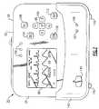
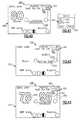
- FIG. 4is a front perspective view of a charging cradle that is used in connection with the vital signs monitoring device of FIGS. 1-3 ;
- FIG. 5is a front view of the vital signs monitoring device of FIGS. 1-3 as mounted in the charging cradle of FIG. 4 ;
- FIG. 6is a schematic block diagram of a patient monitoring system including the vital signs monitoring device of FIGS. 1-3 and the charging cradle of FIG. 4 ;
- FIG. 7is another front view of the vital signs monitoring device of FIGS. 1-3 as mounted in the charging cradle of FIGS. 4 and 5 , illustrating the user interface thereof;
- FIG. 8is a front view of the vital signs monitoring device of FIGS. 1-3 with an attached strap permitting hand-held operation thereof;
- FIG. 9is a alternative view of the vital signs monitoring device of FIGS. 1-3 using a patient-wearable harness;
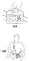
- FIG. 10depicts the vital signs monitoring device of FIGS. 1-3 , as used in a patient transport application;
- FIG. 11depicts the vital signs monitoring device of FIGS. 1-3 as mounted to a bed rail and attached to a large display;
- FIG. 12depicts the vital signs monitoring device of FIG. 11 as attached to a charging cradle and an interface housing for the large display;
- FIG. 13depicts the vital signs monitoring device of FIGS. 11 and 12 as mounted in a charging cradle and directly attached to the large display;
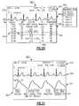
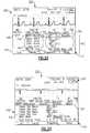
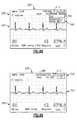
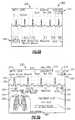
- FIG. 14illustrates two sample display screens indicative of the information that can be captured by the vital signs monitoring device of FIGS. 1-3 and displayed by the large display;
- FIG. 15illustrates an example of a display screen of the vital signs monitoring device of FIGS. 1-3 according to one display mode
- FIG. 16depicts another example of a display screen of the vital signs monitoring device according to another display mode for the vital signs monitoring device of FIGS. 1-3 ;
- FIG. 17depicts yet another exemplary display screen according to yet another display mode for the vital signs monitoring device of FIGS. 1-3 ;
- FIG. 18depicts yet another example of a display screen according to yet another display mode for the vital signs monitoring device of FIGS. 1-3 showing trended tabular data;
- FIG. 19depicts the toggling between various display modes using the vital signs monitoring device
- FIG. 20illustrates another display screen showing how the display cursor is used to highlight a displayed item to permit navigation
- FIG. 21illustrates another example of a display screen of the vital signs monitoring device of the present invention and illustrating how the SELECT button is used to select a highlighted item for navigation;
- FIG. 22is an exemplary control menu accessed through selection of the highlighted item of the display screen of FIG. 21 ;
- FIG. 23depicts another exemplary control menu for the vital signs monitoring device in accordance with the present invention.
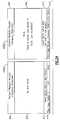
- FIG. 24depicts side by side examples of display screens presented to a user of the vital signs monitoring device upon powering up of the device, depending upon whether patient-related data and settings have been previously stored by the device;
- FIG. 25is an exemplary set-up menu for the vital signs monitoring device
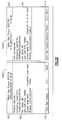
- FIG. 26is an exemplary set of information display windows for the vital signs monitoring device
- FIG. 27is a configured data display screen of the vital signs monitoring device in which patient information is being entered
- FIG. 28is another display screen depicting a patient information entry panel of the display screen of FIG. 27 ;
- FIG. 29depicts an exemplary change patient mode menu for the display screen of the vital signs monitoring device of FIGS. 1-3 ;
- FIG. 30depicts a confirmation display screen that is displayed by the vital signs monitoring device in accordance with the invention when a patient mode is changed by the user;
- FIG. 31is an exemplary display screen of the vital signs monitoring device of the present invention including a time/date control menu
- FIG. 32is an exemplary display screen of the vital signs monitoring device of the present invention including a waveform source menu
- FIG. 33is another exemplary display screen of the vital signs monitoring device depicting a different waveform source
- FIG. 34is another exemplary display screen of the vital signs monitoring device including a waveform size menu
- FIG. 35is a display screen of the vital signs monitoring device depicting an ECG set-up menu in accordance with an aspect of the present invention
- FIG. 36is another example of a function performed in the ECG set-up menu of FIG. 35 ;
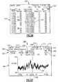
- FIG. 37is an exemplary respiration waveform as displayed by the vital signs monitoring device.
- FIG. 38depicts a portion of an exemplary display screen of the monitoring device and in particular an SpO 2 control menu
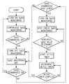
- FIG. 39is a flow chart relating to a SpO 2 spot checking feature of the vital signs monitoring device of FIGS. 1-3 ;
- FIG. 40is an exemplary display screen of the vital signs monitoring device of the present invention, including a primary vital signs display screen with the SpO 2 icon highlighted after SpO 2 has been turned off;
- FIG. 41is a drop down pulse oximeter spot check menu accessed through the window navigation of FIG. 40 ;
- FIG. 42is an exemplary display screen detailing portions of the SpO 2 spot-check feature in accordance with the present invention.
- FIG. 43is a later version of the display screen of FIG. 42 illustrating pulse oximetry data
- FIG. 44is an exemplary display screen of the vital signs monitoring device illustrating a digital manometer feature
- FIG. 45is the display screen of FIG. 44 at a later time during an NIBP reading, in progress;
- FIG. 46is the display screen of FIGS. 44 and 45 at a later time following the NIBP measurement including depicting markers/indicators for the user with respect to systolic, diastolic and mean pressure values;
- FIG. 47is an exemplary Power Off display screen of the vital signs monitoring device
- FIG. 48is an exemplary display screen of the vital signs monitoring device depicting in part, a wireless mode drop-down menu
- FIG. 49is a display screen accessed and displayed by the vital signs monitoring device when the device is disconnected from the wireless network;
- FIGS. 50-52depict examples of an exemplary display screen according to yet another display mode for the vital signs monitoring device of FIGS. 1-3 illustrating snapshots of vitals signs data captured by the device;
- FIG. 53depicts a snapshot display screen similar to FIGS. 50-52 , but further including a trends data selection menu;
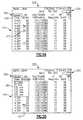
- FIGS. 54-56depict various exemplary display screens of tabular trended patient data as displayed by the vital signs monitoring device of the present invention.
- FIG. 57depicts yet another example of a display screen according to yet another display mode for the vital signs monitoring device of FIGS. 1-3 , showing trended graphical data;
- FIG. 58depicts an exemplary alarm display screen of the vital signs monitoring device of FIGS. 1-3 ;
- FIG. 59depicts an exemplary equipment alert display screen of the vital signs monitoring device of FIGS. 1-3 ;
- FIGS. 60 and 61illustrate exemplary display screens for the vital signs monitoring device, including an alarms set-up menu in which audible alarms can be enabled or disabled;
- FIG. 62illustrates examples of display screens in accordance with the present invention, including a parameter control menu wherein alarm limits can be temporarily customized for an individual patient;
- FIG. 63is a signal output indicating how electrical noise can be discriminated from pacer signals as detected by the device from a selected ECG vector.
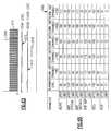
- FIGS. 64 and 65depict portions of an exemplary configuration worksheet used for configuring individual alarm limit settings to predetermined percentage amounts for the monitoring device in accordance with one version of the invention.
- the herein described patient monitoring device 20is defined by a housing 24 that receives input from a plurality of sensors, each forming part of physiologic sensor assemblies 28 , 32 and 36 , in this instance ECG, SpO 2 (pulse oximetry) and blood pressure (NIBP) assemblies.
- the housing 24includes a display 88 for vital sign numerics, waveforms and other patient data, as well as a user interface 92 , FIG. 2 , that permits operation of the monitoring device 20 .
- the display 88is provided on a front facing side of the housing 24 , as well as a plurality of adjacent actuable buttons defining the user interface 92 .
- the display 88is a quarter (QVGA) color display, the display according to this embodiment being approximately 3.5 inches (measured diagonally). More particularly and according to this embodiment, the display 88 is an LCD having a pixel count of 240 by 320.
- the herein described display 88preferably includes a backlight (not shown) to improve readability of the display under low ambient light conditions.
- the housing 24As to the profile of the herein described device 20 , the housing 24 according to this specific embodiment is approximately 5.3 inches in height, 7.5 inches in width, and 2.0 inches in depth. In spite of the lightweight design, however, the herein described monitoring device 20 is extremely durable and rugged wherein the device is equipped to handle various loads that may be encountered in a patient-related setting.
- the housing 24includes a center or intermediate rubberized bladder 26 disposed between a front housing half and a rear housing half that is disposed peripherally therebetween about the device housing 24 in order to assist in cushioning the monitoring device 20 from impact or shock loads and to retain the interior of the device from dust or other contaminants. To further assist in cushioning the monitoring device 20 , each of the corners of the housing 24 are curved to provide an effective contour.
- a battery compartment(not shown) is also formed within the housing 24 , the cover of the battery compartment being essentially flush with the rear facing side 61 of the housing such the compartment does not protrude from the overall profile of the monitoring device 20 .
- the rear facing side 61 of the housing 24further includes a set of rubberized pads or feet 58 , enabling the monitoring device 20 to be placed on a flat surface, as needed.
- each of the buttons comprising the user interface 92are elastomerized to aid in the overall durability and ruggedness of the monitoring device 20 , the buttons being positioned so as not to overly protrude from the facing surface 84 of the housing 24 and allowing the device to maintain a relatively compact profile.
- the compact profile of the device housing 24enables the monitoring device 20 to be patient wearable.
- a pair of tabs 132 , FIG. 2 , provided on opposing lateral sides of the device housing 24enable the monitoring device 20 to be secured to a patient-wearable harness 135 , such as shown in FIG. 9 , or alternatively a strap 137 can be attached to the side tabs 132 , as shown in FIG. 8 , permitting hand-held and portable operation of the monitoring device 20 .
- the strap 137can be used additionally for transport operations along with a transport belt 139 , such as shown in FIG. 10 , with respect to a gurney 138 or other transport apparatus.
- the herein described monitoring device 20can be suitably positioned upon a table or other flat surface using the rubberized pads 58 provided on the rear facing side 61 of the device housing 24 .
- the herein described monitoring device 20is extremely lightweight.
- the entire assemblage shown in FIG. 1weighs approximately two pounds.
- a plurality of physiologic sensor assembliesare tethered to the housing 24 , including an ECG sensor assembly 28 , an SpO 2 sensor assembly 32 and a non-invasive blood pressure (hereinafter NIBP) sensor assembly 36 , respectively, the sensor assemblies being shown in FIG. 1 only for the sake of clarity.
- NIBPnon-invasive blood pressure
- each tethered physiologic sensor assembly 28 , 32 , 36is now provided for the sake of completeness. More particularly and in brief, the SpO 2 sensor assembly 32 is used to noninvasively measure oxygen saturation of arteriolar hemoglobin of a peripheral measurement site of a patient, such as the wrist, a finger, a toe, forehead, earlobe or other area. Reusable or disposable sensor probes can be used.
- a finger clamp 60is shown in FIG. 1 , the clamp having a light emitter and a light detector that can be used to detect pulse/heart rate as well as blood oxygen saturation through pulse oximetry.
- the finger clamp 60is tethered by means of a cable 64 extending to a pinned connector that mates with a corresponding female connecting port 44 , FIG. 3 , that is provided on the exterior of the device housing 24 .
- the concepts relating to pulse oximetry in generalare commonly known in the field and do not form an inventive part of the present invention.
- the ECG sensor or monitoring assembly 28includes a lead wire assembly, wherein either a three-lead or a five-lead ECG can be utilized according to the present embodiment.
- the herein pictured ECG sensor assembly 28 of FIG. 1comprises a set of lead wires 68 , each having electrodes 70 at the ends thereof to permit attachment, in a conventionally known manner, to the body of a patient, the lead wire assembly comprising a harness 71 that is attached to a connection cable 72 having a connector which is matingly attachable to the connection port 40 of the device housing 24 .
- the ECG sensor assembly 28is further utilized herein with respect to a respiration channel of the herein-described monitoring device 20 in order to determine the rate or absence (apnea) of respiration effort through the determination of ac impedance between selected terminals of ECG electrodes 70 , thereby determining the respiration rate of a patient using impedance pneumography based upon movements of the chest wall using a designated reference lead wire.
- Heart rate according to the present embodimentis detected for the herein described device 20 using the ECG sensor assembly 28 .
- the ECG sensor assembly 32creates a waveform (ECG vector) for each lead and further includes a QRS detector that can be adjusted depending upon the patient mode selected.
- the ECG sensor assembly 28is further configured to determine heart/pulse rate, if selected, according to the present embodiment as well as mark pacer spikes in the resulting ECG waveforms by way of a pacer detection circuit.
- the ECG sensor assembly 28 according to the present embodimentfurther includes selectable notch filters of 50 Hz and 100 Hz, 60 Hz and 120 Hz, respectively.
- the NIBP sensor assembly 36indirectly measures arterial pressure using an inflatable cuff or sleeve 76 , which is attached to the limb (arm or leg) of a patient (not shown).
- the remaining end of a connected hose 80includes an attachment end that can be screwed into a fitted air connector fitting 48 that is provided on the top facing side of the housing 24 .
- the air connector fitting 48is connected to a pump (not shown) disposed within the monitoring device housing 24 in order to selectively inflate and deflate the cuff 76 to a specified pressure, depending on the type of patient, using the oscillometric method. Pressure changes are detected by means of circuitry in order to determine systolic, diastolic and mean arterial pressure (MAP).
- MAPmean arterial pressure
- the NIBP sensor assembly 36is capable of performing manual, automatic and a turbo mode of operation, as described in greater detail below.
- the assembly 36can also be equipped, in this embodiment, when ECG is also being monitored, with a motion artifact filter if ECG is also being monitored.
- the filter according to the present embodimentemploys a software algorithm that can be used to automatically synchronize the process of NIBP measurement to the occurrences of the R-wave of the ECG waveform, thereby increasing accuracy in cases of extreme artifact and diminished pulses.
- An example of a suitable NIBP artifact filteris described in U.S. Pat. No. 6,405,076 B1, the entire contents of which are herein incorporated by reference.
- NIBP and ECG sensor assembliesuseful for incorporation into the herein described monitoring device 20 are manufactured by Welch Allyn Inc., of Skaneateles Falls, N.Y., among others. With regard to each, the form of sensor assembly can be varied depending on the type of patient, (i.e., adult, pediatric, neonatal) by selective attachment to the connection ports 40 , 48 that are provided on the monitoring device 20 . Each of the foregoing sensor assemblies according to the present embodiment further include electrosurgery interference suppression. As noted, pulse rate can be detected from either the SpO 2 or the NIBP channels of the monitoring device 20 .
- each of the above physiologic sensor assemblies 28 , 32 , 36are internally connected electrically to a CPU 174 that is contained within the housing 24 of the monitoring device 20 .
- signal processing for each of the physiologic sensor assemblies 28 , 32 , 36is performed internally through resident processing circuitry; for example, the SpO 2 sensor assembly 32 of the present embodiment utilizes the Nellcor Puritan MP506 architecture while the NIBP sensor assembly 36 is based upon a design, such as those used presently in the Micropaq and Propaq vital signs monitors, including, for example, an NIBP Module, Part 007-0090-01, manufactured and sold by Welch Allyn, Inc. Though not shown in FIG.
- the resident circuitry for each of the sensor assemblies 28 , 32 , 36are all integrated into a single logic board wherein the ECG and respiration parameters utilize a common processor, such as a Motorola MPC 823 processor of the CPU 174 .
- a common processorsuch as a Motorola MPC 823 processor of the CPU 174 .
- the remaining physiologic parametersSpO 2 and NIBP are implemented in a more modular fashion, as shown in FIG. 6 , and utilize their own processors. It should be readily apparent, however, that the electronic packaging of the various processing elements of the physiologic sensor assemblies 28 , 32 , 36 of the monitoring device 20 can easily assume various configurations for purposes of the present invention and other versions could easily be contemplated.
- the contained battery pack 170is interconnected to the CPU 174 , the latter including a microprocessor, memory, and resident circuitry, wherein each are connected to the tethered sensor assemblies 28 , 32 , 36 in order to enable processing storage and selective display of the signals provided therefrom as well as perform power conversion between the charging circuit of an optional charging cradle 140 and the contained battery pack, including circuitry to prevent overcharging of the contained battery pack 170 (i.e., 12 volts to 5 volts), as described in greater detail below.
- the CPU 174including a microprocessor, memory, and resident circuitry, wherein each are connected to the tethered sensor assemblies 28 , 32 , 36 in order to enable processing storage and selective display of the signals provided therefrom as well as perform power conversion between the charging circuit of an optional charging cradle 140 and the contained battery pack, including circuitry to prevent overcharging of the contained battery pack 170 (i.e., 12 volts to 5 volts), as described in greater detail below.
- the CPU 174includes available volatile and non-volatile storage for patient data, in the form of Flash memory and SRAM, though other form as are also possible, the CPU 174 being further connected to the display 88 .
- the CPU 174 according to this embodimentis presented on a single logic board along with the processors for the physiologic sensor assemblies 28 , 32 , 36 .
- the CPU 174is intended to handle device-specific aspects, such as alarm limits, display generation, and enabling and disabling of certain features, wherein the physiologic sensor assemblies 28 , 32 , 36 predominantly only relate data for use by the CPU 174 .
- CPU 174controls the operation of the device 20 , including patient modes, pressures, voltages and the like, either as a factory default setting, or configured, as described below either through the user interface 92 , a remote monitoring station 184 , FIG. 6 , and/or a connected PC 192 , FIG. 6 .
- the monitoring device 20 as schematically represented in FIG. 6further optionally includes a wireless radio card/transceiver 180 , enabling bi-directional wireless communication with at least one remote monitoring station 184 , such as, for example, the Acuity Monitoring Station manufactured and sold by Welch Allyn Inc., using the radio card as inserted in an internal PCMCIA expansion slot (not shown).
- the radio card 180according to this embodiment is an IEEE 802.11 compliant radio card that connects to an antenna 182 that is also disposed within the housing 24 of the monitoring device 20 for transmission over a 2.4 GHz frequency hopping spread spectrum (FHSS) wireless local area network (WLAN) using access points 186 .
- FHSSfrequency hopping spread spectrum
- a lower or bottom facing surface 120 of the device housing 24includes a latching member 124 , FIG. 2 , as well as an electrical port 128 , FIG. 2 , each of which are used in conjunction with an optional charging cradle 140 , FIG. 4 , described in greater detail below.
- the battery pack 170is contained in the rear of the device housing 24 within a rear compartment (not shown).
- the battery pack 170provides portable power for the monitoring device 20 wherein the battery life is dependent upon certain operational modes of the device, as described below.
- the battery pack 170is rechargeable by means of charging circuitry contained within the optional charging cradle 140 , FIGS. 4 , 5 .
- the battery pack 170includes at least one rechargeable lithium-ion battery, such as those manufactured by Sanyo Corporation.
- the battery pack 170includes two rechargeable batteries.
- the monitoring device 20is capable of operation in a stand-alone mode using the contained battery 170 as a power source, the battery according to this embodiment having an average runtime of up to approximately 24 hours, depending on the usage of the device.
- the charging cradle 140permits DC power from a wall adapter 171 , shown only schematically in FIG. 6 , or other source to be supplied to the contained rechargeable battery pack 170 through charging circuitry contained in the cradle and power conversion circuitry contained in the monitoring device.
- the use of the optional charging cradle 140permits the monitoring device 20 to be operated regardless of the status of the contained battery (i.e., charged or uncharged), therefore enabling use of the monitoring device 20 as a stand-alone or networked bedside monitor. That is, the foregoing operation can permit both the internal display of patient data as well as wireless transmission of stored patient data to the central monitoring station 184 .
- the charging cradle 140is defined by an open-topped receptacle 144 having a molded or otherwise defined internal cavity that is sized to receive the lower half of the monitoring device 20 .
- the receptacle 144is designed to allow operation of the monitoring device 20 via the user interface 92 , as shown in the attached view of FIG. 5 , when the device is attached thereto.
- a monitor release button 148is provided on a front facing side 152 of the receptacle 144 . The monitoring device 20 is engaged by aligning the bottom facing surface 120 , FIG.
- a pinned electrical connector 160 adjacent the latching element 156mates with the corresponding electrical connector 128 , FIG. 2 , provided on the bottom facing side 120 , FIG. 2 , of the device housing 24 , FIG. 2 , and thereby provides electrical connection between the monitoring device 20 and the charging cradle 140 , as schematically shown in FIG. 6 .
- a rear engagement portion 164 of the charging cradle 140includes a curved hanging bracket 166 , permitting the charging cradle and attached monitoring device 20 to be attached to a bedrail, as shown, for example, in FIG. 11 .
- the hanging bracket 166can further include at least one other mount (not shown) that permits attachment to separate apparatus, such as a fluid-IV pole (not shown).
- the hanging bracket 166can include both attachment modes (bedrail, IV pole).
- the hanging bracket 166is separably removable by way of threaded fasteners (not shown) or other means from the rear engagement portion 164 to permit other attachment arrangements, such as those discussed below with reference to FIGS. 11-13 .
- the bottom surface of the charging cradle 140further includes a plurality of support feet 149 , FIG. 5 .
- the support feet 149are provided at each corner of the bottom surface in order to permit placement onto a flat surface, such as a table 203 , FIG. 12 .
- a pair of indicators 167 , 168are provided on the front facing side 152 of the charging cradle 140 wherein according to this embodiment indicator 167 is a status indicator and indicator 168 is a power indicator.
- the power indicator 168in this instance, a green LED, indicates that power is connected to the charging cradle 140 .
- the status indicator 167in this instance, a multi-colored LED, is used to indicate the charging status of the monitoring device 20 . For example and if the monitoring device 20 is in the charging cradle 140 and power is properly connected to the charging cradle from the wall adapter 171 , FIG. 6 , the status indicator 167 will be illuminated (e.g., either green or yellow) or will be off.
- the status indicator 167When the status indicator 167 is green, charging is proceeding normally. The status indicator 167 is turned off when the battery pack 170 reaches full charge. When the status indicator 167 is yellow, the indicator indicates that a fault has occurred and the battery pack 170 is not charging properly. Such faults may occur, for example, as those caused by a severe discharge of the battery 170 , a cradle logic fault, incorrect seating of the monitoring device 20 within the charging cradle 140 , improper engagement of the connectors or other similar anomaly.
- the power indicator 168may be illuminated (e.g., green), indicating power is capable of being delivered to the monitoring device 20 in spite of the fact that a charging fault (yellow) has occurred.
- the cradleattempts to charge the contained battery pack 170 . If the battery pack 170 is fully charged when the monitoring device 20 is inserted into the charging cradle 140 , the status indicator 167 turns green momentarily and upon sensing of a full charge, the indicator is turned off. In the instance that the battery is overcharged at the device 20 , however, no power for charging the battery pack 170 will be delivered to the device.
- the herein described monitoring device 20is shipped to a user/facility with a preset factory configuration for each setting and behavior of the device. It is desirable for most facilities to reconfigure any received patient monitoring device 20 to conform the device to local protocol and adapt the device to the clinical environment to which the device will be used.
- the monitoring device 20might be used in a neonatal unit although the factory calibration/configuration is preset for adult patients.
- the usercould custom configure the monitoring device 20 upon each use to allow the device to be used for neonatal patients, as described in greater detail herein, it may be preferable to have neonatal mode installed as the default patient mode for a monitoring device.
- a PC 192can be used in conjunction with the charging cradle 140 to download a new configuration file to the monitoring device(s) 20 prior to use in a facility for service.
- the charging cradleincludes a USB data port 165 , FIG. 4 , provided on the exterior of the charging cradle 140 that provides an isolated serial data-link connection between the attached monitoring device 20 and the personal computer (PC) 192 , FIG. 6 , through a USB cable.
- the charging cradle 140serves as an intermediary or pass through to the monitoring device 20 to configure the monitoring device prior to use in a facility by creating a configuration file that includes a plurality of setting choices that can be completed, for example, by the bioengineer of the hospital, to adapt onto or to replace pre-existing factory settings initially provided with the device 20 that are stored or programmed within the CPU 174 .
- the PC 192includes utility software that enables the creation of a utility configuration worksheet into which default settings and limits can be entered. The worksheet is then converted into the new configuration file that is downloaded into the CPU 174 of the monitoring device 20 through the intermediary charging cradle 140 .
- settingscan be preset using the downloaded configuration file wherein some of these features, if not enabled, cannot be controlled by the clinician/user.
- These settingscan include, for example, the default language of the monitoring device 20 , the default patient mode of device operation, forms of display available to the user and/or their ordering, the enablement of device specific features, such as, for example, lockout of the user interface 92 and display 88 , time limits on alarms and alerts, data trending, and the enablement of alarm and alert tones. All or certain of the factory settings can be adjusted by appropriate entries provided on the configuration worksheet created at the PC 192 and communicated through the data link between the CPU 174 and the PC 192 . Therefore, this PC configuration results in a set of revised default settings and monitoring device behaviors.
- FIGS. 64 and 65A portion of an exemplary configuration worksheet is shown in FIGS. 64 and 65 with regard to one specific feature that can be enabled with regard to alarm management. Specifics relating to this feature are described in greater detail in a later section.
- the worksheet 198 shownis a paper version that is completed by a user in advance to using the configuration utility, the latter providing a PC worksheet version that provides similar entries.
- the usercompletes the paper configuration worksheet 198 , FIG. 64 , to organize the features for configuration or can directly input selections into the utility worksheet provided at the PC 192 , FIG. 6 .
- the configuration fileis created with instructions to override the factory settings when the file is downloaded to the monitoring device 20 through the serial data link provided by the charging cradle 140 .
- the PC 192also permits stored data to be printed automatically when the monitoring device 20 is activated and attached to the charging cradle 140 , also using the associated USB data port 165 , FIG. 4 .
- the PC 192is connected to a suitable peripheral printer, in this instance, a laser printer 195 , also schematically shown in FIG. 6 , wherein the monitoring device 20 and PC are programmed to automatically permit data transfer to occur.
- the data that is storedis in the form of trended data and “snapshots”, the latter term referring to numeric and waveform data covering a predetermined time period that is electively taken by a user using the snapshot button 116 .
- the charging cradle 140can alternatively serve to provide an intermediary interconnection between the herein described monitoring device 20 and a large display 200 .
- This form of interconnectionpermits all processed data in the monitoring device 20 to be transmitted in real time in order to permit viewing of the data substantially as though users were at the central monitoring station 184 , as opposed to the smaller and constricted device display 88 . That is, a series of waveforms can be displayed for viewing, for example, as shown in FIG. 14 .
- the large display 200according to this embodiment includes a VGA card and suitable attachment bracketry in the form of an interface box or housing 202 .
- FIGS. 11-13Several embodiments for interconnection of the monitoring device/charging cradle assembly to the large display 200 through the interface box 202 are illustrated in FIGS. 11-13 .
- the monitoring device 20is already attached to the charging cradle 140 in the manner described above.
- the charging cradle 140is attached to a bedrail using the hanging bracket 166 .
- a VGA cable 205is then connected from the USB data port 165 , FIG. 4 , to connectors that are provided on the interface box 202 .
- the charging cradle 140serves as an intermediary for data transfer from the patient monitoring device 20 .
- the curved bracket 166FIG. 4
- the charging cradle 140 and the monitoring device 20 /charging cradle 140can be placed on a table 203 adjacent the large display 200 , the latter being attached in each instance to a wall.
- the interface box 202is directly attached to the rear of the charging cradle 140 .
- the monitoring device 20 and charging cradle 140can be attached to the interface box 202 directly on the large display 200 through the display bracketry and bracketry that is provided on the charging cradle 140 , respectively.
- a sample data output of the large display 200is shown in FIG. 14 , this output substantially replicating that seen by the remote monitoring station 184 , FIG. 6 , and considerably an increased amount of data than is viewable on the integrated display 88 .
- the charging cradle 140can include additional features to provide a level of adaptability for a system incorporating the herein described monitoring device 20 .
- an additional physiologic parameter assemblycould be attached to the charging cradle 140 in lieu of or in addition to the monitoring device 20 wherein physiologic data could still be uploaded to the monitoring device 20 when the device is attached to the charging cradle for wireless transmission to the central monitoring station 184 , FIG. 6 .
- the charging cradle 140can be equipped with at least one physiologic sensor assembly (not shown) wherein data collected by the at least one sensor assembly can be inputted to the CPU 174 of the monitoring device 20 for display and transmission.
- the life of the battery pack 170is highly dependent on the use mode of the device. As noted above and according to this embodiment, about 24 hours of runtime is possible.
- the level of battery chargeis displayed by the monitoring device 20 according to this embodiment, as described below.
- the user interface 92includes five (5) closely arranged buttons forming a keypad.
- a center buttonreferred to throughout as a SELECT button 96
- SELECT button 96is generally used to select a highlighted item that is displayed by the device, as discussed in greater detail below, or to confirm a choice.
- buttons 100 immediately surrounding the SELECT button 96are generally used (up, down, left or right) in order to directionally guide a display cursor in order to highlight an item, for example, or to increase or decrease a selected parameter value.
- buttonsare also provided, according to this embodiment, on the front facing side 84 of the housing 24 , these buttons being used for specified or dedicated purposes, including a display button 104 , permitting the user to cycle between a plurality of varied display formats, such as those shown in FIGS. 15-19 , an alarm silence/resume button 108 permitting the user to temporarily and manually silence or resume an existing patient alert/alarm tone, an NIBP start/stop button 112 for manually starting or stopping an NIBP measurement, and finally the above referred to snapshots button 116 that automatically stores a predetermined time period of vitals-signs data in both tabular and waveform format, an exemplary snapshot display screen being shown in FIG. 50 .
- buttonsfurther include a visual representation of their function for ease of use by the clinician; for example, the directional control buttons 100 include specific directional arrow indicators, the display button 104 includes a display icon, the NIBP start/stop button 112 includes a depiction of a blood pressure cuff, the snapshots button 116 includes a camera icon and the SELECT button 96 depicts a circle thereupon. Additional details concerning the functions defined by each of the above-listed buttons, and the implementation and operation of the user interface 92 of the herein described monitoring device 20 will be described in greater detail in a succeeding section of this description.
- a series of visual status indicatorsare also provided on the front facing side 84 of the monitoring device 20 .
- Three status indicators 169are arranged in linear fashion above the display 88 at the center of the front facing side 84 of the device housing 24 , and are electrically connected to the CPU 174 , FIG. 6 .
- the visual status indicators 169are to apprise the user of the operational status of the monitoring device 20 ; that is, whether the monitoring device 20 is operating normally, confirmation of the connection of the monitoring device 20 and the proper patient being connected to a network or to a remote monitoring station 184 , FIG. 6 , and/or whether the herein monitoring device 20 is subject to an alarm and/or alert condition. It should be readily apparent that the number and location of these indicators can be suitably varied.
- each of the status indicators 169are illuminated with a specific colored light (e.g., red, yellow or amber, and green), indicating an alarm condition, an alert condition, and normal operation of the monitoring device 20 , respectively.
- a specific colored lighte.g., red, yellow or amber, and green
- an “alarm”is indicative of a patient condition, such as vital signs reading(s) that is outside of acceptable limits.
- the red indicator 169is illuminated.
- An “alert” conditionby comparison, is not as serious as an “alarm” condition and is typically indicative of a device-operational problem, such as a low or discharged battery or a detached lead.
- the yellow status indicator 169is illuminated when this type of condition is indicated.
- the status indicators 169can further either illuminate steadily or flash in order to indicate the severity of the problem. For example and according to this embodiment, this severity can be defined between an equipment alert and an alarm condition.
- the monitoring device 20further includes a speaker 161 , shown only schematically in FIG. 6 , for signifying audible tones, as needed, for example, that may be sounded during an alarm or alert condition. Additional details relating to alarm and alert management using the herein described monitoring device 20 are described in a later portion.
- Each of the tethered sensor assemblies 28 , 32 , 36provide physiologic parameter data in the form of analog signals and the like to the CPU 174 of the monitoring device 20 .
- the herein described monitoring device 20is capable of continuously monitoring each of the physiologic parameters (NIBP, pulse rate, 3 and 5 lead ECG, respiration, SpO 2 ) depending on the number and type of sensor assemblies that are connected therewith.
- each of the SpO 2 sensor assembly 32 and the blood pressure (NIBP) sensor assembly 36include their own individual processors contained within the monitoring device 20 that operate the sensor assemblies with regard to the acquisition of and processing of data (that is, each of the above sensor assemblies include appropriate algorithms and resident circuitry for processing the acquired signals).
- the ECG/respiration sensor assembly 28includes attendant circuitry within the CPU 174 .
- any or all of the sensor assembliescan include modular processors or the processing can be carried out within a single integrated logic/CPU board.
- the signals then being processedare stored into the memory of the CPU 174 for display and for wireless transmission using the contained transceiver 180 and antenna 182 to the central monitoring station 184 using the communications network, as described in the previously incorporated U.S. Pat. No. 6,544,174. Additional data, such as patient demographics, can be added for storage and display by the user, as discussed below, or may alternately be uploaded to the monitoring device 20 from a list of available patients from the remote station 184 .
- the monitoring device 20can transmit patient information, once configured with the network, for display of all stored parametric data at the remote monitoring station 184 .
- the monitoring device 20is also connectable through the USB port 165 , FIG.
- the charging cradle 140enabling operation as a bedside monitor in which serial attachment to the PC 192 through the USB port 165 enables interconnectivity to a peripheral device, such as a printer 195 , as previously described or alternatively, to the larger display 200 .
- the monitoring device 20can also transmit wirelessly to the remote monitoring station 184 using the connected radio 180 and antenna 182 .
- the versatility of the herein described monitoring device 20therefore provides a number of distinct advantages.
- the herein described monitoring device 20can be used as a transport monitor in that the device is battery powered.
- the use of the rubberized back feet or pads 58 , the rear interior loading of the battery pack 170 and general packaging and compactness of the profile of the monitoring device 20present a lightweight and extremely versatile unit that allows for both wired and wireless connectivities enabling the device to work in either a stand-alone or a networked capacity.
- the charging cradle 140FIG. 4 , permits the monitoring device 20 to be used for bedside applications by providing a source of power for the contained battery pack 170 as needed and for charging same.
- the charging cradle 140serves as an intermediary device that enables data transfer to either a large display 200 or printing to a locally connected computer 192 .
- the locally connected computer 192can also be used to selectively modify factory programmed configuration settings of a monitoring device 20 through new default settings that can be downloaded to the monitoring device 20 .
- Each display screenis defined by a stored preformatted template consisting of a number of discrete panels with each panel including a number of elements that are defined by various combinations of textual, numeric, waveform, graphical and/or other forms of data, as described herein that are obtained from the CPU 174 and generated onto display 88 .
- a self-diagnostic or operational testis initiated. If the self test is unsuccessful, at least one of the status indicators 169 of the monitoring device 20 is illuminated, depending on the error.
- a start-up display screen 400 ( a ), 400 ( b ), FIG. 24appears on the display 88 , FIG. 1 , with the display screen having user-selectable options to continue monitoring a patient (in the event patient data has been saved), start monitoring a new patient, obtain system information, or enter a demonstration mode.
- each start-up display screen 400 ( a ), 400 ( b )commonly includes a customer ID panel 404 , a notice panel 408 , a bottom message panel 412 and a context menu panel 416 , respectively, as read from the top of the display screen.
- the notice panel 408 of start-up display screen 400 ( a )indicates by way of a textual message that no data has been saved.
- monitoringcan be resumed for that patient when the monitoring device 20 is powered up again.
- the settings of the monitoring device 20are also saved into the nonvolatile memory of the CPU 174 . In this instance, a decision must be made by the user as to whether the data is to be saved and monitoring will continue with the same patient or whether the stored patient data should be deleted and a new patient monitoring mode should be initiated.
- the customer ID panel 404provides information about the facility and device that have been previously entered and stored in an information screen, such as shown in FIG. 26 , shown as 420 ( a ), 420 ( b ).
- the information screen 420 ( a ), 420 ( b )can be accessed from the Info option of the context menu panel 416 .
- Each of the information screens 420 ( a ), 420 ( b )also include a context menu panel 416 at the bottom thereof, including the same options as the start-up screens 400 ( a ), 400 ( b ), respectively.
- this informationcan be added to the memory of the device 20 , such as during the creation and downloading of the configuration file using PC 192 , FIG. 6 , as described previously.
- the context menu panels 416provide a means for navigation between various control screens of the herein-described monitoring device 20 .
- Each context menucontains a number of menu options disposed along the length of the panel 416 .
- the user interface 92 and in particular, the directional buttons 100 and the SELECT button 96are used to highlight and select a highlighted option by movement of the display cursor.
- selection of one of the context menu optionsexecutes a new mode of the monitoring device 20 or creates a new display screen, as described in greater detail below.
- the content and options available in context menusvary depending on the display screen which utilizes them. Examples of various context menus 416 that are used in the operation of the monitoring device 20 are provided in FIGS. 25 , 28 and 47 , each of which are detailed in a later portion of this description.
- the context menu panel 416indicates the following available user-selectable options; namely, a Start New Patient option, an Info option, and a Demo option.
- the Start New Patient optionpermits the user to enter a patient monitoring mode.
- the Info optionreverts the user to an information screen, such as either 420 ( a ), 420 ( b ) shown in FIG. 26 , while selection of the Demo menu option provides access to a demonstration mode for the monitoring device 20 .
- the above three (3) user-selectable optionsare provided in the context menu panel 416 of display screen 400 ( b ), as well as a Continue Patient option.
- the “patient data stored” display screen, 400 ( b ), FIG. 24is displayed.
- the userverifies that the displayed name and patient ID match that of the current patient and upon verification, and highlights the Continue Patient option in the context menu panel 416 at the bottom of the display screen 400 ( b ). If the latter option is selected through use of the directional arrow buttons 100 and pressing the SELECT button 96 , then any stored data is loaded and the monitoring device 20 is ready for monitoring, including the continued implementation of any previous custom configuration settings that are particular to the patient.
- Start New Patient option(onto which the display cursor is highlighted in the display screen 400 ( b )) is elected and the SELECT button 96 is pressed, then all previous data (and custom configuration settings) are deleted and a new patient monitoring mode is initiated.
- a first configured data display screen 430appears, as shown in FIG. 27 .
- a unique auto IDis provided in a status panel 320 , and more specifically in a device ID field 434 that is highlighted using the SELECT button 96 , accessing a Patient Information Entry screen 440 , as shown in FIG. 28 , the latter consisting of a table of alphanumeric characters 444 that can be highlighted and sequentially entered into the proper field 448 to create entries.
- the name of the new patientis then entered as well as the patient ID and the patient room number.
- this datacan be entered using the remote monitoring station 184 , FIG.
- each of the sensor assemblies 28 , 32 , 36have been suitably attached to a patient (not shown) and the monitoring device 20 and that the patient has been monitored for an extended period of time by the device.
- a number of specifically configured display screen template formatsare stored in memory of the CPU 174 and are available for viewing at the user's option, these templates including associated vital signs data in the form of either current or trended data.
- An exemplary default display screen 210FIG. 15 , for purposes of this discussion is enabled by way of the configuration settings of the monitoring device 20 , this screen being the current display screen displayed to the user during monitoring.
- the format of this particular display screen 210includes a status panel 320 , a large waveform panel 324 and a parameter panel 328 , respectively, as read from the top of the display screen.
- the displayed data that is shown in FIG. 15 as contained in the various fields of the status panel 320includes the following elements: the patient's name, if available, shown as 204 , the patient ID 208 , and the patient room number 209 .
- Each of the preceding elementswere manually added to the internal memory of the monitoring device 20 and added at start-up as previously described above with regard to FIGS. 27 and 28 by the clinician or alternatively in the case of a network-enabled monitoring device 20 , by the remote monitoring station 184 , FIG. 6 , prior to monitoring of the patient over a wireless communications link. In the former instance, this information as entered in the Patient Entry Information display screen 440 , FIG.
- the status panel 320further includes a communication status icon 212 (if the device includes a wireless transceiver 180 , FIG. 6 , and antenna 182 , FIG. 6 ) and a time display 216 , as well as a battery status indicator or icon 220 , the latter providing an indication of available battery power.
- the battery status icon 220can provide an indication as to whether the contained battery pack 170 is full, partially full indicating that the battery is not fully charged, but not fully discharged, partially full and charging, low battery wherein the battery has approximately 30 minutes of runtime remaining, low battery and charging, very low battery wherein the battery has approximately 5 minutes of run time remaining and very low battery but charging.
- an alertcan be provided by the monitoring device 20 .
- the battery status icon 220would remain after acknowledgement of the alert. Alerts and their management are discussed in a later portion of this description.
- the CPU 174is programmed to automatically disable the NIBP sensor assembly 36 upon a low battery indication being determined wherein a status message is displayed to the user if the manual NIBP start/stop button 112 is pressed. If the monitoring device 20 is charging in the charging cradle 140 and a low battery and charging indication appears via icon 220 , then the NIBP sensor assembly 36 is enabled.
- the mode (adult, neonatal, pediatric) of the patient 224as well as the mode of the device 228 (simulation, monitoring) are each applied within separate fields that are provided in the status panel 320 of the display screen 210 .
- the mode of the device 228stimulation, monitoring
- Each of the foregoingare typically based upon default settings of the herein described monitoring device 20 , unless modified by the user, as described in greater detail below.
- the depicted waveform 240is current and can originate from a number of sources.
- the panel 324further provides text identifiers relating to the specific waveform source 232 and waveform size (display scale) 236 .
- a waveform representative of an ECG vectoris represented.
- the waveform depicted, including its size and source as displayed,are also typically based upon a default setting of the monitoring device 20 , wherein each setting may be changed locally by the user or remotely by the remote monitoring station 184 , as described below.
- alarm status indicators 268are also represented in the parameter numerics panel 328 at the bottom of the display screen 210 for each listed parameter.
- These alarm indicators 268represented herein by bell icons indicate whether the upper and lower limits for each physiologic parameter are on, the upper alarm limit is on but the lower alarm limit is off, the upper limit is off but the lower limit is on, or all alarms are off through an appropriate representation of an alarm symbol, whether in blank or solid, and combinations thereof. Alarms are described in greater detail in a later portion of this description.
- FIGS. 16-19depict additional exemplary display screens that can be selectively displayed by the user in addition to the single waveform display screen 210 depicted in FIG. 15 .
- Each of these additional display screensinclude a specifically defined template format that is stored into memory for generation by the CPU 174 onto the display 88 .
- these additional user-selectable display screensinclude a dual waveform display screen 332 , shown in FIG. 16 , a large numeric display screen 336 , shown in FIG. 17 , which is similar to that shown also in FIG. 27 , and a single waveform with tabular trended data display screen 340 , as shown in FIG. 18 .
- each of the same reference numeralsare used to label similar data and symbology herein for the sake of convenience and clarity.
- the above-noted display screenspermit live monitoring of vital sign numerics, waveforms and/or trend information in various user-selectable formats as now described.
- the dual waveforms display 332 screen of FIG. 16is a variation upon the single waveform display screen 210 of FIG. 15 .
- This display screen 332provides patient and monitoring device information as well as two waveforms and available parameter numerics.
- the defined format of this display screen 332includes a status panel 320 that includes each of the elements of the single waveform display screen 210 referred to above including patient name 204 , patient ID 208 , patient room number 209 , communication status indicator 212 , time display 216 , battery status indicator 220 , patient mode indicator 224 , and display mode indicator 228 .
- Two small waveform panels 344are provided in lieu of the single panel of the display screen 210 , FIG.
- the display screenfurther including a live or current parameters numerics panel 328 , similar to that of the single waveform display screen 210 , FIG. 15 .
- Each of the waveform panels 344are smaller than that of the single waveform data display screen 210 , but contain similar information including waveform source 232 and size indicia 236 .
- the waveforms presented in the panels 344can be from two different sources or can be provided alternatively as a cascaded waveform from one source that is presented on two adjacent waveform panels. In the example shown in FIG. 16 , separate ECG and SpO 2 waveform 240 , 242 , respectively, are depicted.
- the live parameter numerics panel 328like the preceding includes a heart rate/pulse rate numeric and text identifier 244 , the most recently taken NIBP numeric 248 including the systolic/diastolic and mean (parentheses) numerics and text identifiers as well as a corresponding time stamp, a respiration numeric and text identifier 252 , and an SpO 2 numeric and text identifier 256 including a dynamic blip bar 260 showing pulse amplitude.
- Alarm icons 268in the forms of bell icons, are also provided for each of the preceding parameters in this panel 328 .
- the large numerics display screen 336 shown in FIG. 17is similar to that depicted in FIG. 27 , labeled as 430 (but without data or patient information entered).
- This display screen 336is defined by a format that includes a status panel 320 , also similar to that described for the display screens of FIGS. 15 and 16 , and a large numerics panel 352 provided in lieu of waveform panels.
- the large numerics panel 352contains the same information provided in the panel 348 discussed with regard to FIG. 16 other than that the icons and associated text identifiers are significantly larger and disposed in differently assigned fields in the display screen 336 .
- the live or current parameters panel for this display screenincludes a large HR/PR numeric element 244 as well as a text element and an alarm icon 268 , a large SpO 2 numeric element 256 along with an associated text element, alarm icon 268 and blip bar 260 , a large NIBP numeric element 248 representative of the most recent measurement as well as a text element and time stamp of measurement and alarm icon 268 and a large respiration numeric element 252 along with an associated text element and alarm icon 268 .
- the alarm icons 268these provide an indication of those alarms that are currently enabled and those alarms that are currently disabled.
- each alarm icon 268relates to the lower alarm limit and the right hand side of the icon refers to the upper alarm limit.
- a solid bellshown herein as white, indicates that the alarm is enabled while a blackened portion of the bell indicates that the alarm is disabled.
- Alarmsare provided (upper and lower limits) for each of heart rate/pulse rate, respiration, NIBP (systolic, diastolic and mean) and SpO 2 .
- NIBPdiastolic and mean
- SpO 2the lower limit of the mean NIBP is currently disabled while the remaining alarm limits are each currently enabled.
- the alarm icons 268further permit the user to access menus, as described in greater detail below, by which the alarms can be enabled or disabled, upper and lower limits can be set, and volume controls for audible tones can be adjusted.
- the herein described monitoring device 20can not only display current or recent numerics and waveforms, but is also storing data for trend analysis.
- several display formatsrelate to trended data, wherein this data can be reproduced either graphically or tabularly. Snapshot data is also stored in addition to any periodic or randomly taken measurement data and data stored by the device 20 based upon continuous monitoring.
- FIG. 18illustrates a combination waveform/tabular trend display screen 340 .
- a waveform as well as live parameter numerics and tabular list of trend dataare depicted in a generated template format on the display 88 pertaining to a monitored patient.
- the pre-defined format of this display screen 340includes a status panel 320 , similar to that described with regard to FIG.
- a single waveform panel 344including a waveform and text identifiers relating to the waveform source 232 and size 236 , respectively, similar to those described in FIG. 16 , a trends live numeric panel 356 and a trends data panel 360 , respectively.
- the trends live numerics panel 356includes a data display header 364 relating the form of data presented (tabular, graphical, or other) followed by a linear set of current heart rate, respiration and SpO 2 parameter numerics and the most recent NIBP measurement, as well as text identifiers beneath each corresponding parameter numeric and the current blip bar 260 for SpO 2 .
- a “Time” table headingis also provided beneath the data display header 364 .
- the trends data panel 360 of this display screen 340includes a tabular (in this instance) arrangement of stored numerics arranged in a table, allowing the user to navigate through a predetermined period (e.g., 24 hours) of stored trends with entries for time, heart rate/pulse rate, NIBP, respiration and pulse oximetry provided beneath each corresponding text identifier.
- trend datais listed in one minute intervals for each of time, heart rate/pulse rate, respiration, and SpO 2 , respectively, when any NIBP readings are successfully made using the NIBP start/stop button 112 or through automated mode, or when an SpO 2 spot check reading is made.
- the time interval between trend entriesis a configuration setting of the monitoring device 20 that can be selectively adjusted by the user, for example, depending on the patient.
- the exemplary display screen 340is configured to list seven (7) entries in the display panel 360 according to the present example, although this parameter can be varied.
- a twelve (12) entry tableis provided on a tabular trend data display screen 470 .
- No waveform datais provided on this screen 470 , which is defined by a status panel 320 , a trends live numerics panel 356 , similar to that shown in FIG. 18 , and a trends data panel 474 .
- up to 24 hours or other predetermined time period of trend datacan be stored into memory.
- a scrolling navigation icon 374is also provided next to the time listing in order to permit the user to access any of the stored data, as needed.
- the herein described device 20can display trended data in a graphical form.
- An exemplary graphical trend data display screen 380is shown in FIG. 57 .
- This display screen 380is defined by a format that includes a status panel 320 , as described above, a live trends numerics panel 356 , and a graphics display panel 384 with graphical trend data 294 having a time scroll 388 at the bottom thereof.
- the data shownpertains to a single parameter (in this example, heart rate), wherein the parameter data being displayed can be varied, as described in greater detail below.
- FIGS. 18 , 19 and 56user-captured snapshots are identified separately in the tabular listing of trend data with a camera icon 477 .
- a sample snapshots viewing screen 298is shown in FIG. 50 . Reviewing of snapshot data is discussed in a later portion of this description.
- the display button 104is used to cycle through the configured display formats. As shown in FIG. 19 , the display modes can be toggled between large numeric display screens, waveform/numeric display screens, and trend data display screens. According to this example, pressing the display button 104 allows the user of the monitoring device 20 to toggle between a large numerics display screen 336 , a single waveform display screen 210 , and a tabular trend display screen 470 , respectively. Depending on the configuration settings of the herein described monitoring device 20 , the display button 104 could be used to navigate between each of the display screens shown in FIGS. 15 , 17 and 18 , respectively, wherein a default version of each type of display screen can be determined.
- each and every display screen according to this embodimentincludes a single element—the current context—labeled herein as 407 , that is shown by a first colored field (e.g., blue) in order to highlight the element.
- a first colored fielde.g., blue
- pressing the SELECT button 96causes the monitoring device 20 to replace the current display screen with another display screen that is related to the current context.
- the monitoring device 20is programmed to then display a SpO 2 control menu 402 , having a specified format and shown in FIG. 22 , onto the primary display screen.
- the directional buttons 100can be used to scroll the display cursor in order to highlight the item to be selected by the user.
- a second colored fielde.g., green
- the current values of multiple parametersare identified within a given context.
- the current context of the SpO 2 monitoring menu option 403is highlighted in the primary or first color (e.g., blue), while the current settings 404 of the SpO 2 parameters according to this embodiment are highlighted in the second color (e.g., green).
- the second colore.g., green
- indicationscan be provided on a display screen to a user using various colors or are provided with separate indicators in accordance with this embodiment.
- items listed in red as shown in the display screen of FIG. 20indicate readings 396 that exceeded a given alarm limit (either an upper or a lower limit) in addition to the current context 392 , for example.
- Other examplesare provided.
- the trend tabular display screen 470 presented in FIG. 56depicts a number of readings 475 that have been compared to known limits and have been suitably identified.
- the herein described monitoring deviceincludes a set of embedded menus that are used for at least two purposes.
- certain menuse.g., context menus
- second menuspermit adjustments to be made to the monitoring device 20 .
- These adjustmentsare intended to be temporary and typically relate to the specific patient being monitored.
- device settingsare typically configured through factory default settings.
- a technique using a configuration file using the charging cradle 140 as an intermediary relative to a portable computer 192 , FIG. 6has also been discussed as an option to permit at least some of the factory settings to be overridden.
- the monitoring device 20further permits custom configuration at the user level using a variety of display menus that can be accessed through the user interface 92 .
- display menusFor purposes of explanation herein, two (2) main types of menus can be accessed, pop-up (also referred to throughout the discussion as drop-down) menus and control menus. Each of these menus will now be described with regard to the present embodiment.
- Other menusassist in navigation through and between various display screens in addition to the herein described display button 112 . These menus have been alluded to with regard to the start-up display screens, FIG. 24 , and information screens, FIG. 27 , noted above and are referred to as context menus.
- pop-up or drop down menusare provided to allow a user to temporarily make configuration settings for the herein described monitoring device 20 as well as to vary certain formats, for example, for display.
- the menusalso affect various modes of the device, among other features, as will now be described.
- the display cursoris used to highlight an item in any primary display screen 210 , 332 , such as shown in FIGS. 15 , 16 , using the directional buttons 100 of the user interface 92 and the SELECT button 96 is pressed to access a corresponding drop-down menu. As shown, for example, in FIG.
- the resulting pop-up or drop down menuappears as an overlay onto the primary display screen 590 wherein the format of each corresponding menu includes a header text and a plurality of listed menu items or options.
- there are at least ten (10) drop down menus available for the herein described monitoring device 20each of which enable certain settings of the device to be temporarily altered for a particular patient.
- a patient mode drop down menu 540is accessible by highlighting the displayed patient mode field 224 as provided on any primary vital signs display screen 210 , FIG. 15 , in the status panel 320 thereof and pressing the SELECT button 96 .
- the current or default patient mode 544in this case, an Adult mode, is highlighted and the directional arrow buttons 100 of the user interface 92 , FIG. 2 , enable the mode to be changed to pediatric mode, shown as 556 .
- all stored vital signs dataincluding any snapshot and trended data, for the patient is deleted automatically from the CPU 174 and all monitoring device settings revert to the default settings for the new patient mode that is selected.
- a confirmation screen 550when changing a patient mode, appears as an overlay on the display screen, shown herein as 554 , indicating that parameter values will be changed to default settings for the mode now selected and further indicating that all stored information will be lost if the patient mode is changed. Confirmation is then required before any new mode selection can be implemented by the user wherein confirmation changes the patient mode and removes the confirmation message panel 550 from the display screen 554 .
- the resulting display screen(not shown) then indicates pediatric in the patient mode field 224 thereof.
- the monitoring device 20includes a wireless RF radio card 180 and internal antenna 182 which when enabled, automatically establishes a wireless communications link between the monitoring device 20 and the central monitoring station 184 . While within the confines of a wireless LAN (Local Area Network), this connection is suitable within range of a suitable access point 186 .
- the communication status indicator or icon 212 located on the status panel 320 of any primary display screen 210 , such as those shown in FIG. 15is configured to provide an indication of the status of the wireless connection with the remote monitoring station 184 , which is limited, for example, given the distance between the monitoring device 20 and an access point 186 on the network.
- the monitoring device 20is not enabled for communication with the remote monitoring station 184 .
- This status indicator 212can provide certain information concerning the connection as follows according to this embodiment: If the communication status indicator 212 flashes, this is an indication that the monitoring device 20 is associated with an access point 186 , but the device is not communicating with the remote monitoring station 184 . If the communication status indicator 212 has a line appearing through it, the indicator being presented as shown in FIGS. 15-18 as an antenna symbol, then the monitoring device 20 is not communicating with an access point 186 , FIG. 6 , and is not communicating with the remote monitoring station 184 .
- the communication status indicator 212is located at the upper right hand corner of the status panel 320 in any primary display screen. Similar indications can be made using the status indicator 212 when the monitoring device 20 is communicating with a PC 192 and not with the network, and whether the monitoring device is associated with the network and is communicating with the remote monitoring station 184 .
- this selective disconnectionis highly desirable given the considerable drain to the battery resources that occur when attempting to restore communications with the remote monitoring station 184 , FIG. 6 , as the device would continue to attempt to restore communications even when the device is out of range.
- this selective disconnectionis achieved through software wherein the user highlights the communications status indicator 212 of primary display screen 210 , FIG. 15 , or any display screen having a status panel 320 using one of the directional arrow buttons 100 pressing the SELECT button 96 .
- a disconnected wireless icon popup or drop-down menu 560(if the device is enabled with a wireless transceiver 180 and antenna 182 ) is accessed by which the user is permitted to selectively toggle into and out of a disconnected wireless mode.
- the pop-up menu 560includes a set of menu options, including a disconnect option 564 which the user can elect to disconnect the monitoring device 20 from the wireless network by scrolling using the appropriate directional arrow buttons 100 and highlighting the disconnect menu option. This election is further indicated to the user by one of the status indicators 169 , FIG. 2 , provided on the front facing side 84 of the monitoring device 20 .
- the deviceprovides only local respiration, NIBP, HR/PR and SpO 2 alarms or equipment alerts.
- a Disconnect message 568is also displayed to the user next to the communication status indicator 212 on the display screen 210 , the latter having a symbol indication of disconnection, as shown in FIG. 49 .
- disconnect featureprovides an advantage in that battery/device power is conserved while the monitoring device 20 is out of range. During the time the above wireless disconnect feature is utilized, trended vital signs data continues to be stored within the memory of the CPU 174 , as per normal operation.
- the communication status indicator 212When the monitoring device 20 is again within range of the network, the communication status indicator 212 , FIG. 15 , provides a signal that the monitoring device 20 is within range and network connection can be restored by again highlighting the communication status indicator 212 to access the wireless mode menu 560 , highlighting a Reconnect menu option (not shown), and pressing the SELECT button 96 . This selection automatically causes a prompt that is displayed to the user for information concerning the patient and the network. A similar message is displayed at the remote monitoring station 184 . Reconfiguration and handshaking of the herein described monitoring device 20 with the wireless network is as described in the previously incorporated U.S. Pat. No. 6,544,174. At the time network connection is restored, all trended data stored during the time the monitoring device 20 was disconnected is transmitted to the remote monitoring station 184 , FIG. 6 , over the wireless network.
- patient data gathered by the monitoring deviceis continuously stored at the remote monitoring station 184 .
- patient informationcan be accessed and administrative functions can be performed including admitting, transferring and discharging the patient from the remote central monitoring station unit, editing the patient description (name, primary care physician), and reviewing and printing patient data, including trends and waveforms.
- FIGS. 32 , 33Other pop-up or drop-down menus are provided according to this embodiment for temporarily configuring other settings of the monitoring device 20 include a waveform source popup menu 580 , see FIGS. 32 , 33 , that provides user selections for determining which waveform is being displayed (e.g., resp, ECG including choice of vector) and for switching, for example, between a single waveform display screen 210 and a dual waveforms display screen 332 , FIG. 16 .
- This latter menu 580is accessed by the user by highlighting the waveform source field 232 on the display screen 210 and pressing the SELECT button 96 .
- the monitoring device 20further includes means for cascading a display in order to sweep a single waveform through two panels, thereby showing or presenting a waveform covering a 2 ⁇ time period (e.g., 6 seconds to 12 seconds).
- FIG. 32illustrates an example ECG waveform having a default menu option 584 , with FIG. 33 depicting a user option 588 for a respiration waveform using the menu 580 .
- a waveform size drop-down menu 600permits user selection relating to the size of displayed ECG, SpO 2 or respiration waveforms relative to any display screen 332 by highlighting the waveform size text identifier 236 , located in the waveform panel 344 and selecting a menu option 604 .
- a sample respiration waveform 608FIG. 37 , is shown that is augmented by this size menu.
- a trend display pop-up menu 640permits selection between various forms of trended data (tabular, waveform, snapshot) by highlighting the data display header 364 , FIG. 52 , in the trends live numerics panel 356 , FIG. 52 , of a trended display screen, in this instance, a snapshots display screen 590 .
- tabular screensare shown in FIGS. 54-56 and a graphical trend display screen 380 is depicted in FIG. 57 .
- a trend view interval popup menu 660is accessed by highlighting the Time heading in the data display panel 474 , the menu permitting the time intervals between trended data listed to be selectively varied by the user.
- Additional pop-up menusinclude a snapshot waveform source popup menu, a graphical source pop-up menu and a snapshot selection pop-up menu.
- Each of these embedded menusare similarly accessed by highlighting the appropriate text identifier and pressing the SELECT button 96 to affect temporary configuration setting changes for the device 20 .
- an SpO 2 spot check or random pop-up menu 620FIG. 41 , is also provided, details being provided for this latter feature in a succeeding section.
- a “control” menu for purposes of this embodimentincludes a topic name for the current context (for example, SpO 2 , in FIG. 22 ), each menu being defined by a stored formatted template comprising a first display panel having a column of parameters with one of the parameters highlighted (for example, SpO 2 Monitoring), and a column of options, with one item in the set of options being highlighted (for example, Standby, On, 100 , On, 90 , Low).
- the primary (e.g., blue) highlighted itemindicates the parameter that is currently enabled for modification, while secondary (e.g., green) highlighted items indicate each of the current settings for all parameters in the control menu.
- Each control menufurther includes a context menu at the bottom of the control panel in order to enable navigation as well as permit confirmation or cancellation of a choice/option selected by the user, such as in the instance of the start-up display screens 400 ( a ), 400 ( b ), FIG. 24 .
- the monitoring device 20 described hereinincludes at least nine (9) control menus that are accessible by the user.
- each control menucan provide customization of the configuration of the monitoring device 20 for the current patient and to confirm choices.
- each control menucan be accessed using the directional arrow buttons 100 to locate and highlight the item to be controlled and pressing the SELECT button 96 , as previously described. It will be readily apparent that the number and arrangement of these menus is exemplary and that other variations and modifications are possible within the intended ambits of the invention. Additionally, it should further be noted that each of the following controls can be similarly modified from the remote monitoring station 184 over the wireless connection with the monitoring device 20 .
- a time setup control menu 700allows the time, date and time format used by the monitoring device 20 to be locally modified by the user. More particularly and according to this embodiment, the time format (12 hour/24 hour), hour, minute, month, day, year, year and year format can be selectively adjusted by the user. The time and date can also be confirmed for correctness as the monitoring device 20 is capable of displaying time in either 12 hour (AM/PM) or 24 hour format, and displays the date in either a month/day/year, day/month/year, or other suitable format. According to this embodiment, the date does not appear in the primary display screens but does appear in both a snapshot list and associated snapshot data, details of which are described below.
- a number of parameter control menusare accessible, including an NIBP control menu, an SpO 2 control menu, a HR/PR control menu and a respiration control menu, respectively.
- Each of these parameter control menuscan be accessed by either selecting the parameter text identifier in any primary display screen such as 210 , FIG. 15 , or by selecting the alarm bell icon 268 .
- the NIBP control menupermits the setting of upper and lower alarm limits for each of the systolic, diastolic and mean pressures as well as the selection of a digital manometer, the selection of a specific NIBP mode and the time interval used when an automatic mode is enabled.
- An exemplary NIBP control menu 720is shown in FIG. 23 .
- the NIBP control menu 720is defined by three panels according to the present embodiment.
- the uppermost panel 722includes a listing of menu options that can be elected by the user.
- the second field 724includes a listing of submenu options associated with each menu option from the first panel 722 .
- the third panelis a context menu panel 416 that includes a series of navigational options.
- NIBP measurementscan be taken through a user-selected automatic mode in which blood pressure readings are taken at prescribed time intervals.
- the automatic NIBP modecan be enabled by highlighting the NIBP text identifier in the primary vital signs display screen 210 , FIG. 15 , and pressing the SELECT button 96 . The above selection accesses the NIBP control menu 720 , shown in FIG.
- NIBP Mode optionis scrolled to and the Auto menu suboption in the second panel 724 is selected using the directional control buttons 100 to highlight the desired mode and pressing the SELECT button 96 .
- An appropriate time intervalcan then be selected by highlighting the Auto Time Interval (min) suboption in the panel 724 that will provide automatic blood pressure measurements at the prescribed intervals (e.g., 3 min, 5 min, 15 min, 30 min, 60 min, etc). It should be noted that the incorrect placement or failure to place the cuff 76 on the patient will still enable automated mode, but an equipment alert will be sounded by the monitoring device 20 .
- the automatic NIBP modecan be disabled by highlighting the NIBP text identifier on the primary vital signs display screen 210 using the directional control buttons 100 , pressing the SELECT button 96 to access the NIBP control menu, FIG. 23 , and then highlighting NIBP mode from the NIBP control menu 720 and selecting the Manual menu option using the appropriate directional control buttons 100 .
- any blood pressure readingcan be taken manually after positioning the correct cuff 76 , FIG. 1 , and hose 80 , FIG. 1 , relative to the patient, screwing the hose end into the NIBP air connector fitting 48 , FIG. 3 , provided on the top facing side 52 , FIG. 3 , of the housing 24 and pressing the NIBP start/stop button 112 .
- all manual and other NIBP mode measurementsare stored as trended data by the monitoring device 20 .
- an enhanced blood pressure measurement mode(herein referred to as “Turbo” mode) in which the monitoring device 20 automatically initiates a blood pressure measurement reading in a conventional manner and then takes as many readings as is possible within a predetermined time period (e.g., 5 minutes), provided this option is enabled by way of default configuration settings such as through the downloaded configuration file.
- Turbo modeas defined herein, can be set through the user interface 92 by highlighting the NIBP text identifier in any primary vital signs display screen 210 and pressing the SELECT button 96 to access the NIBP control menu 720 , FIG. 23 , as previously described. The NIBP Mode menu option can then be highlighted with the Turbo suboption then being selected using the appropriate arrow button 100 . Selecting the NIBP start/stop button 112 or highlighting the NIBP Mode Manual menu option from the NIBP control menu 720 will restore the monitoring device 20 to a manual NIBP measurement mode.
- the patient monitoring device 20further includes a digital manometer that can be selectively displayed for the user during a blood pressure measurement procedure.
- This featureis enabled through the NIBP control menu 720 which is accessed in the manner previously described above from any of the primary vital signs display screens.
- the Manometer option listed therein in the top panel 722is highlighted using the directional arrow buttons 100 .
- Pressing the SELECT button 96causes a manometer menu 730 to appear as an overlay on the display screen 210 , as shown in FIG. 44 .
- Pressing the NIBP start/stop button 112starts the NIBP measurement cycle as previously described.
- a manometer pressure indicator bar 734 located at the bottom of the display screen 210dynamically displays the pressure reading, as shown in FIG. 45 .
- measurement numerics 742appear below the waveform grid of the display screen 210 and each of the systolic, diastolic and MAP values for the measurement are displayed as markers 738 , if valid readings are obtained for each along a defined manometer scale, as shown in FIG. 46 .
- Adjustment and enablement of the alarm limits and the remaining options on the control menu 720are selected in the same manner described above.
- the Exit menu optionif selected by the SELECT button 96 , reverts the user back to the previous primary vitals signs display screen, the Trends option changes the display screen to a trends viewer screen that causes a tabular or waveform history to be displayed, the Snapshots menu option causes a series of 21-second waveform snapshots of the current patient's vital signs to be selectively viewable, and the Setup menu option accesses the setup control menu.
- the SpO 2 control menu 402permits setting of either continuous or a random (herein also commonly referred to as a spot-check) SpO 2 measurements, the setting of alarm limits and setting of the pulse tone.
- continuous measurement of at least one physiologic parameter other than SpO 2is enabled through the CPU 174 and the tethered physiologic parameter sensor assemblies, while permitting the user, by means of the user interface 92 , to manually “spot check” SpO 2 . That is to say, SpO 2 can be periodically or randomly checked on the patient (not shown) while simultaneously maintaining continuous monitoring of at least one other physiologic parameter.
- an alertis generated each time that SpO 2 readings are interrupted, such as when the sensor is disconnected from the patient after the monitoring device 20 has begun to take SpO 2 readings.
- any number of randomly taken readingscan be taken, attaching and detaching the sensor repeatedly without generating any alarms.
- a flowchartgenerally describes the herein referred to random or spot checking monitoring feature.
- the SpO 2 monitoring function of the monitoring device 20is turned off.
- the usercan turn the continuous SpO 2 monitoring function off manually with the user interface 92 by scrolling to the primary vital signs display screen, FIG. 21 , and highlighting the SpO 2 text identifier 407 and pressing the SELECT button 96 .
- the precedingaccesses the SpO 2 control menu 402 , FIG. 22 .
- This control menu 402is defined by two panels; a first panel 746 that includes a list of menu options and suboptions and a context menu panel 416 permitting navigation out of the spot-check mode.
- Highlighting the SpO 2 Monitoring menu option 403using the left arrow button 100 to highlight the Off suboption and pressing the SELECT button 96 then turns off the continuous monitoring function and turns the spot checking feature.
- the SpO 2 monitoring functionWhen the SpO 2 monitoring function has been deactivated, it can then be reactivated by the user, either for continuous monitoring or for a one-time spot check reading.
- the pulse oximeter sensor 60FIG. 1
- the pulse oximeter sensor 60FIG. 1
- the userhighlights SpO 2 on the primary vitals sign display screen, FIG. 40 , and presses the SELECT button 96 .
- the userUpon pressing same, the user then highlights SpO 2 @ XX:XX and presses the SELECT button 96 accessing a SpO 2 drop-down menu 620 , FIG. 41 .
- This menu 620that appears as an overlay onto the display screen (not shown in this view) includes On, Off and Spot Check options.
- the On option 622permits the user to reenable the continuous SpO 2 monitoring feature.
- the Off option 624disables the continuous monitoring feature and enables spot checks.
- the Spot check option 626is highlighted in this instance, since the SpO 2 continuous monitoring function has already been disabled.
- the spot checking feature of the herein described monitoring device 20is controlled through logic contained within the monitoring device 20 that allows the SpO 2 hardware to first initiate the sensor assembly 32 , FIG. 1 , and acquire a stable SpO 2 measurement from the patient as sensed by the apparatus. According to this embodiment and referring to FIG.
- the primary vital signs displayindicates SpO 2 Spot Check with a text identifier “SEARCH” 628 displayed above a Spot Check text identifier 629 to indicate that the monitoring device 20 is waiting for pulse oximetry data from the patient.
- the SpO 2 indicatorif SpO 2 is used to determine pulse rate begins to display pulses and after approximately 30 seconds, the SEARCH text identifier 628 disappears and a pulse oximetry reading 256 appears, FIG. 43 .
- the SpO 2 subsystemis powered down automatically. The stable SpO 2 reading that has been obtained is then displayed for a predetermined period of time or until a new spot check reading of SpO 2 is acquired.
- the preceding stepsare then repeated wherein the SpO 2 sensor assembly 28 is initiated; a stable reading is acquired and then displayed for a predetermined period of time.
- any other parameters that are continuously monitored, such as ECGare unaffected by the spot-checking functionality feature.
- Each of the HR/PR and respiration control menus as well as the NIBP and pulse oximeter control menuspermit the setting of upper and lower alarm limits.
- the HR/PR control menu(not shown) further permits adjustment of volume or enablement of the heart tone, and the preferred source (either SpO 2 or ECG) for heart rate wherein the current source is also highlighted.
- the respiration control menu(not shown) also permits the selection of the reference leadwire used from the ECG monitoring assembly.
- set-up control menusare also provided to the user in order to define the behavior of the herein described monitoring device 20 .
- a typical set-up menucan be accessed according to this embodiment from any main display screen, such as those depicted in FIGS. 15-19 , by performing the steps of: highlighting the battery indicator icon 220 , HR/PR text identifier, SpO 2 text identifier, NIBP text identifier, respiration text identifier or the alarm icon 268 ; pressing the SELECT button 96 thereby accessing a parameter control menu; highlighting the setup option located in the context menu panel 416 at the bottom of the display screen 210 ; and pressing the SELECT button 96 again.
- an “alarm”warns of a patient condition, such as a vital-sign reading that is outside of acceptable limits.
- the red light status indicator 169 , FIG. 2on the front facing side 84 of the monitoring device 20 flashes and the numerics of the violating alarm limits shown on the display 88 turn red, such as depicted in FIG. 20 .
- the display cursormoves automatically to the displayed item that caused the alarm and if not suspended, an audible alarm tone also may sound.
- a sample alarm condition 850is shown in FIG. 58 in a single waveform display screen 210 .
- the heart rate for the monitored patienthas exceeded a predetermined limit, as highlighted by 854 .
- notification of the alarm conditionmay also be transmitted to the remote monitoring station. Pressing the alarm silence/resume button 112 will silence current alarm tone for a predetermined period of time (e.g., 90 seconds).
- An “alert”refers to an equipment or device condition, such as a low battery or a detached lead.
- the yellow light indicator 169 on the monitoring device 20flashes and a message describing the condition appears on the display 88 in a message panel.
- An example of an equipment alert, in this instance, the disconnection of an ECG lead,is shown by the display screen of FIG. 59 .
- Equipment alerts, according to this device embodiment,are indicated by a flashing yellow indicator 169 as well as a highlighted (e.g., yellow) alert message 306 provided conspicuously on the display screen of the monitoring device 20 and repeated sounding of an alert tone, in the instance that the alert is not acknowledged or the cause of the alert is not alleviated.
- an alert tonewill be distinguishable from an alarm tone to a user.
- the depicted equipment alertis an ECG lead failure. Therefore and in addition, a diagram 302 is illustrated with an indication (in this instance a circled X) to indicate at least one disconnected lead. Alarm and alert conditions can also be detected by the remote monitoring station 184 , FIG. 6 , via the wireless network.
- alert conditions detected by the herein described monitoring device 20include, but are not limited to, the following: ECG Faults which can include Lead failure (single, multiple), excessive offset, or detection of unplugged ECG cable; NIBP Faults that can include an air leak, kinked hose, overpressure cuff condition, weak pulses to determine systolic/diastolic pressure, no pulses detected, detection of artifact prevents valid reading, or low battery; Network Communication Faults including the detection of a network communication problem, detection in attachment to charging cradle, low battery, or no SpO 2 detected; and respiration channel faults, such as a noisy signal or lead failure. Still referring to FIG.
- ECG Faultswhich can include Lead failure (single, multiple), excessive offset, or detection of unplugged ECG cable
- NIBP Faultsthat can include an air leak, kinked hose, overpressure cuff condition, weak pulses to determine systolic/diastolic pressure, no pulse
- acknowledgement of the alert by the useris made by highlighting the acknowledge option 864 at the bottom of the display screen and pressing the SELECT button 96 , FIG. 2 . Acknowledgement will remove the message panel and revert the display 88 to the previous display screen format.
- the first techniqueis through pressing the alarm/silence button 108 , which will silence any current alarm(s) for a predetermined period of time (e.g., 90 seconds). It should be noted, that silencing the audible tone does not affect the remaining alarm or alert indicators.
- the alarm tonecan also, according to this particular device embodiment, be suspended for all parameters, thereby preventing the alarm tone from sounding if an alarm condition occurs while monitoring a patient. Suspension is done by the user through accessing an alarms suspend menu 880 that is provided in the set up controls menu 800 , as shown in FIGS. 60 , 61 . If an alarm condition occurs while the alarm tones are suspended, the monitoring device 20 presents visual alarm indicators, but does not sound an audible tone.
- the suspension period of the alarm tonecan be set during configuration of the monitoring device 20 to disable the tone for a predetermined period (i.e., 90 seconds-60 minutes).
- the monitoring device 20can be so preconfigured such that the alarm tone cannot be suspended by the user, for example, through use of the configuration file that is uploaded to replace the factory settings of the monitoring device using the PC 192 , FIG. 6 , as previously described.
- the usercan access the set-up control menu 800 by highlighting the text identifier of the parameter that is highlighted by the alarm.
- the usercan highlight the Alarms option, thereby accessing the Alarms set-up menu 880 .
- the display cursorhighlights the Off menu option wherein a message panel appears in the display screen 210 to use the directional right arrow button 100 in order to highlight the On suboption.
- a count-down timer 884appears below the line in the set-up menu 880 as well as a highlighted indicator 888 in the upper portion of the display screen 210 .
- the alarm toneis again enabled.
- the alarms set up menu 880further permits the volume of the alarm tone to be selectively adjusted by the user.
- each medical facilitydefines the patient alarm limits for adult, pediatric and neonatal patients and then configures the monitoring device 20 with those alarm limits prior to putting the monitoring device into service.
- the usercan locally or custom adjust certain configuration settings of the herein described monitoring device 20 .
- upper and lower alarm limitscan be temporarily customized for an individual patient while the monitoring device 20 is in use.
- This temporary customization featurecan be implemented by the user by highlighting any vital sign of interest from a primary vitals signs display screen and pressing the SELECT button 96 so as to access the control menu for that parameter; in this instance, NIBP, 720 .
- Upper and lower alarm limitscan then be selected by highlighting the current value and using the left and right directional arrow buttons 100 to set the new alarm limit(s), 726 , 728 .
- These new limit valuesare then stored in volatile memory of the CPU 174 , FIG.
- the monitoring device 20is further configured to permit alarm limits to be customized for a particular patient from the remote monitoring station 184 , FIG. 6 , over the bidirectional wireless network using the radio card 180 and antenna 182 to receive new limit values.
- the herein described monitoring devicecan be further configured such that the user can perform alarm management on the monitoring device 20 by permitting the user to actuate a feature provided on the user interface 92 that creates a predetermined percentage change to the alarm limits for a single parameter each time the SELECT button 96 is depressed at the time of an existing alarm.
- the initialization and initial percentage settings for each of the alarm parameter settingsis performed according to this specific embodiment as part of the configuration of the monitoring device 20 prior to use of the monitoring device 20 through the PC 192 using the configuration file to override factory configuration settings, the new settings being stored by the CPU 174 .
- a portion of a sample worksheet 198is shown in FIGS.
- the usercan temporarily silence an alarm through use of the alarm silence/resume button 108 provided on the user interface 92 . Turning the alarm off temporarily, however, in and of itself, does not change the limit. Therefore, if the patient's physiologic parameters are unchanged, the alarm will go off again momentarily depending on the default settings of the monitoring device 20 (e.g., 90 seconds).
- the usercan suspend the alarm tone for a patient for a predetermined period of time in the manner described above using the control menus 800 . This feature also does not change any alarm limits.
- the usercan temporarily change or customize any of the alarm limits individually through features provided on the user interface 92 , using the set-up control menus, as described above, such as 720 or other menu.
- this third techniquecan be accomplished by accessing the control menu for a specific parameter to highlight a specified parameter indicator (such as HR/min or NIBP, for example) and pressing the SELECT button 96 .
- the corresponding parameter control menu, FIG. 62is then displayed, permitting the user using the directional left and right cursor control buttons 100 to set appropriate alarm limits for the patient, the user then highlighting Exit to leave the menu window.
- a fourth techniqueis provided by means of the presently described vital signs monitoring device 20 in which the user can also now automatically and selectively change a parameter alarm limit by a prescribed amount. Rather than incrementally changing the alarm limits, the user can change the alarm limits by a prescribed percentage amount each time the SELECT button 96 for this option is actuated as entered using worksheet 198 , FIG. 64 , via the configuration file.
- the latter featurecan be accessed only during a current alarm(s). For example, upper and lower alarm limits for HR/PR can initially be set to alarm at an upper rate of 90 and a lower rate of 60.
- the alarm limitscan be incremented by a predetermined percentage (e.g., 5 percent, 10 percent, or other). For example, if a five percent change were configured for the herein described monitoring device 20 , the alarm limits would change to 94 (upper)/ 57 (lower) the first time the SELECT button 96 is depressed, 99 (upper)/ 54 (lower) the second time the button is depressed, and so forth.
- a predetermined percentagee.g., 5 percent, 10 percent, or other.
- NIBPsystolic pressure, diastolic pressure and mean pressure
- SpO 2 and respiration rate limitscan be similarly adjusted wherein the amount from factory (default) preset value alarm limit values can be adjusted, depending on the patient mode, for individual parameters as part of the pre-configuration routine using the PC 192 .
- a tabular listing 950is shown in FIG. 65 for appropriate percentage changes to the alarm limits according to one example.
- the ECG monitoring sensor assembly 28FIG. 1 , of the present embodiment includes a respiration circuit provided in the form of an ASIC, wherein breath signals using impedance pneumography supports measurement of respiration rate as well as central apnea.
- the herein described monitoring device 20can monitor heart signs (ECG) and respiration rate using either a 3-lead or a 5-lead ECG cable.
- ECGheart signs
- Using a 3-lead ECG cableone signal waveform for lead I, II, or III can be displayed.
- Using a 5-lead ECG cableeither one or two signal waveforms can be displayed by the monitoring device 20 for leads I, II, III, V, and if enabled in the configuration, aVR, aVL, or aVF.
- the SpO 2 or Resp waveformcan also be displayed in place of the ECG waveform.
- the appropriate ECG cableis plugged into the device housing 24 and appropriate electrode sites are selected on the body of the patient. This selection process is commonly known and does not form a significant part of the present invention. At least three (3) electrode connections are required for ECG/Resp monitoring.
- the monitoring device 20provides a graphic display 302 , FIG. 59 , of a three or five lead ECG attachment with fixed locations being indicated. The locations of the circles shown in the diagram 302 in FIG. 59 do not indicate the exact placement of the electrodes on the patient.
- the monitoring device 20is adapted to indicate whether some lead wires are not connected and to indicate an “ECG Fault” equipment alert and a chest diagram such as shown in FIG. 59 , indicating the general location of the disconnected lead or leads. If the disconnected lead(s) indicate that the waveform source (Lead) used for HR determination, then the monitoring device 20 automatically reassigns, if possible, the Lead used for heart rate (HR). If the reassignment succeeds, the monitoring device 20 then displays another equipment alert with the message “ECG Lead changed”.
- the waveform sourcecan be changed, for example, from Lead I to Lead II by highlighting the waveform source selection icon using the cursor control buttons 100 and pressing the SELECT button 96 .
- the latterwill access the waveform source menu 580 , FIG. 32 , wherein the appropriate option 584 can be highlighted.
- a second waveformcan be added (or deleted).
- the waveform sizecan also be suitably varied by the user by highlighting the current waveform scale and pressing the SELECT button 96 .
- the waveform size pop-up menu 600 , FIG. 34is accessed through the latter selection and a desired scaling factor can be highlighted.
- Respiration rateis also monitored using the ECG monitoring circuit, as noted above, based on impedance pneumography, wherein respirations can be sensed from the ECG electrodes.
- the respiration numericis displayed in the lower right corner of the display screen.
- the waveform source identifier 232FIG. 15
- the SELECT button 96is pressed in order to access the waveform source pop-up menu 580 , FIG. 33 .
- Respiration as a menu option 588is then highlighted and selected. Waveform size can be adjusted in the same manner described previously for the ECG waveforms.
- the monitoring device 20In addition to monitoring the presence of the ECG waveform, the monitoring device 20 also detects the periodic signals emanating from an implanted pacemaker device. To that end, according to the present embodiment and referring to FIG. 35 , if the patient being monitored has an implanted pacemaker device, the monitoring device 20 can indicate the occurrence of pacemaker or pacer signals by activation of the Pacer Indicator option 904 from the ECG set-up control menu 900 , FIG. 36 , if not already configured. When activated, the Pacer Indicator displays and prints vertical dashed lines to indicate pacemaker signals. If the Pacer Indicator option 904 is not enabled, the monitoring device 20 according to this embodiment continues to detect the pacemaker signals, but does not display or print the pacer markers.
- the monitoring device 20displays this signal as a waveform spike, whether the Pacer Indicator option 904 is enabled or not.
- the present ECG circuitalso detects when pacer signals/EMI pulses are occurring too frequently (outside of the periodicity of realistic pacer signals).
- the detection of these pacer signalsis commonly affected by electronic noise (such as EMI—Electromagnetic Interference) triggered, for example, from overhead lights that can hinder the ability to adequately detect a pacer signal from an implanted patient device (i.e., a pacemaker). Electrical noise from a power source can also cause an unclear or noisy waveform.
- the inventionprovides the ability to select amongst the various ECG vectors, each of which has been processed for pacer pulse detection of both polarities and feeds both the pacer pulse detector and a peak/noise floor detector. An example is shown in FIG. 63 .
- the latter detectorgenerally captures a value 908 that is representative of the peak amplitude of real pacer pulses, and also captures a second value 912 that is representative of the peak amplitude of rapidly repetitive noise spikes, as shown in FIG. 63 .
- Meansallow selection of available ECG vectors and after obtaining a peak and noise floor level signal from each, shown as 915 , 916 , respectively, then picking an optimum ECG vector to continue feeding the pacer pulse detector. If the noise floor signal is made available to the user, the user can observe how the magnitude of the noise floor signal changes while moving the monitoring device 20 about in the vicinity of a possible noise source, the latter being shown magnified as 918 .
- the reported signal levelwill generally increase as the monitoring device 20 is moved closer to the noise source and hence serves a directional aid in locating the source of electrical noise. Since it is already known at what level the noise spikes 912 would begin to trigger the pacer pulse detector, it may thus be determined whether a noise source was sufficiently large to cause false pulse detections.
- the principles described hereincan be implemented by hardware, software or a combination of hardware and software.
- the above circuitcan further be used to validate a measurement in order to assess lead wire and electrode integrity for an ECG monitoring assembly.
- This measurement capabilityprovides means for monitoring electrode performance as well as providing a means for proactively changing electrodes, as needed.
- the hardwaredrives a small current through each connected lead wire. This current is directed through the patient to a reference lead wire, also extending from the patient. As a result, each lead wire produces an offset voltage (with respect to the reference lead) based on Ohm's Law.
- each lead wire's offset voltage delta(that is, the voltage difference between each of its lead wires) can be determined, thereby providing a means for qualitatively “ranking” each of the lead wires and electrode assemblies.
- Software included within the monitoring devicecan then be utilized in order to provide an assessment of the electrodes and the lead wires based on the computed deltas, at least to determine the “qualitative state” of the electrodes, (e.g., if one lead wire has a much higher offset than the remaining leads, the most likely cause is an electrode contact issue such as a dry electrode or loss of contact with the patient).
- the “qualitative state” of the electrodese.g., if one lead wire has a much higher offset than the remaining leads, the most likely cause is an electrode contact issue such as a dry electrode or loss of contact with the patient.
- the monitoring device 20also includes a power source filter that can be enabled from the ECG set-up control menu 900 , FIG. 36 .
- the settings for the power source filtershould be applied depending on the power source in the facility.
- the power source filter option 906according to this embodiment includes settings of 60 Hz and 50 Hz.
- NIBPblood pressure
- the herein described monitoring device 20can be further equipped with the selective use of a motion artifact filter, such as the Smartcuf artifact filter manufactured by Welch Allyn, Inc., in order to increase the measurement accuracy in the presence of moderate motion artifacts or diminished pulses.
- a motion artifact filtersuch as the Smartcuf artifact filter manufactured by Welch Allyn, Inc.
- Enablement of an artifact filter featurewould include the steps of mounting each of the ECG and NIBP assemblies to the monitoring device 20 and to the patient respectively and as previously described, and then simultaneously monitoring the patient using each of the above physiologic sensor assemblies.
- the set-up control menu 800would be accessed in the manner described above from a primary vital signs display screen.
- the NIBP menu optionwould be highlighted to access the NIBP setup control menu and then a Smartcuf suboption (not shown) would be highlighted and selected.
- the blood pressure measurementcould be marked with an identifiable symbol on the display screen and on printouts.
- the motion artifact filtercould also be selectively disabled by accessing the control menu in the same manner described above, highlighting the NIBP option and disabling the Smartcuf sub-option.
- buttons of the user interface 96 and the display and/or backlight of the herein described monitoring device 20can be locked out to prevent unauthorized access or use.
- This lock out featurecan be accomplished in several different ways. According to one technique and if the feature is initially enabled using the PC configuration utility, the user can simultaneously hold down the left arrow, the right arrow and the up button simultaneously for a continuous period of time (e.g., 5 seconds). All buttons, including the Power ON/Off button 56 are locked. The buttons are automatically unlocked when an alert or an alarm condition occurs. Similarly, the display 88 and/or backlight can also be locked out by the user using a selective combination of buttons if no operator activity (e.g., no buttons are pressed) has occurred for a predetermined amount of time. The backlight lockout and the display lockout features would again be disabled immediately after an alarm or alert condition occurs.
- the remaining set up control menus that are available to the user according to this specific embodimentinclude that relating to the Demo Mode (Disabled, Low, High).
- the monitoring device 20incorporates additional control menus according to this embodiment including a Device Status Control Menu; and a Message Control Menu.
- the Device Status Control Menupermits the user to see a displayed information screen 420 ( a ), 420 ( b ), such as shown in FIG. 26 .
- the information screen 420 ( a ), 420 ( b )includes separate panels 422 , 424 including the facility name, department name, and other associated information.
- the Message Control Menuis used, for example, with regard to changing of ECG leads in the event of a lead failure, requiring the reassignment of channels.
- At the bottom of each of the control menusare context menu panels 416 , allowing the user to navigate, the context menus for the set-up control menus being identical to those of the parameter control menus.
- FIG. 22A more specific example of using a control menu is now herein described with reference to the display screen depicted in FIG. 22 .
- the down arrow button 100is used to scroll to highlight Lower Limit and the right arrow button 100 is then pressed as many times as necessary in order to increment the limit to the intended limit value; in this instance 95 .
- the herein described monitoring device 20is programmed such that the upper alarm limit cannot be decreased to a level that is lower than the lower alarm limit for the parameter. Similarly, a lower alarm limit cannot be raised to a level that is greater than or equal to the upper alarm limit.
- the down arrow button 100is pressed to scroll down to the HR/PR Tone field and the left or right arrow button is pressed as many times as is necessary in order to highlight OFF. Pressing the SELECT button or the display button 104 will exit the control menu screen and return the display to the previous vital signs display screen.
- the values that are displayed at the time the menu is exitedare the new default values for the monitoring device 20 . If a parameter is changed therefore, a decision must be made by the user prior to leaving the display screen whether or not to keep the previous setting values. If so, these parameters must be returned prior to exiting the control menu.
- buttons 100are therefore used to perform any of the following functions: highlight an item on display, selection of options from a control menu, set-up menu or displayed “pop-up” menu, and changing the values of numeric parameters.
- the display button 104in addition to cycling though the configured display formats as shown in FIG. 19 can also be used to return to a primary vital signs display screen from a control menu and for closing a “pop-up” menu.
- the SELECT button 96is used to perform the following operations: display the control menu for a primary highlighted item, return from a control menu to a primary vital signs display screen, provide access to a set up menu when setup is highlighted by the display cursor, display of tabular and graphical trends when trends is highlighted, display of snapshots when snapshot is highlighted, turn on the display or the back light if either has been turned off by a power save feature of the monitoring device 20 , and displaying a pop-up menu.
- the herein described monitoring device 20in addition to displaying current numerics and waveforms and the most recent measurements also stores a predetermined amount of patient data.
- a predetermined amount of patient dataup to 24 hours (at one-minute intervals) of trends (graphical and/or numeric) information for the patient being monitored can be stored, as well as NIBP and SpO 2 “spot checks” and “snapshots”, as taken selectively by the user in connection with the patient and accessible from the Trends option of the context menu of any control menu, as described below.
- the data from each new readingoverwrites the data from the oldest data stored.
- a snapshot requestis made by pressing the snapshot button 116 , FIG. 7 , which is provided on the front facing side 84 of the device housing 24 .
- the CPU 174Upon depression of the snapshots button 116 , the CPU 174 is programmed to provide a graphical display 298 of a default waveform (ECG, respiration) for a selected lead for a predetermined time period along with additional information, such as shown in the exemplary display screen of FIG. 50 .
- ECGECG, respiration
- This datacan be reviewed at the monitoring device 20 .
- the userhighlights any of the parameter text identifiers (HR/PR, SpO 2 , etc) and then accesses a control menu for that parameter.
- the userthen highlights the context menu panel 416 for that control menu and selects the snapshots option and confirms the selection by pressing the SELECT button 96 .
- Highlighting the Snapshots optioncauses a Snapshots display screen to be displayed, examples of which is depicted in FIG. 51-53 .
- Each of the up to twenty snapshotscan then be viewed by the user. In the example shown in FIGS. 51-53 , five (5) snapshots were taken.
- the snapshot display screen 590includes a status panel 320 at the top of the display screen, a live numerics panel 356 and a snapshot display panel 594 , respectively.
- the snapshot display panel 594displays the stored snapshot for viewing and includes controls for selecting the snapshot file, the data source, the scale of the display and scroll controls.
- a vertical lineindicates the center of the display.
- the waveform and numeric vitals signs data during the 21 secondscan be viewed by the user by highlighting time interval provided at the bottom of the display screen 590 and using the directional (left/right) cursor buttons 100 to scroll the display to the desired time.
- An exampleis shown in FIG. 52 , for five seconds after the trigger point of the snapshot as opposed to FIG. 51 , which is taken one second following the trigger point.
- the waveform source and size of the snapshotcan also be selectively changed by the user for any captured snapshot by highlighting the appropriate icon on the display screen and accessing an associated drop-down menu 580 , 600 , as shown in FIG. 32 , 33 .
- the usercan optionally switch to another type of display or can exit and return to a primary vital signs display screen by highlighting Snapshots in the upper left corner of the display screen and pressing the SELECT button 96 .
- the precedingaccesses a Trends menu 640 , FIG. 53 , wherein highlighting the appropriate option allows the user to navigate to another display screen.
- the monitoring device 20also stores trend data that is viewable in a plurality of user selectable formats.
- Trend datacan be reviewed in a manner similar to that of waveform data by highlighting any parameter icon from any primary vitals signs display screen, FIG. 53 , and pressing the SELECT button 96 .
- Highlighting Trends from the resulting pop-up menu and pressing the SELECT button 96accesses the Trends display screen 470 , an example of which is shown in FIG. 54 .
- the trends display screen 470displays tabular trend data as well as live numerics for the monitored patient, the screen having a format consisting of a status panel 320 , a trends live numerics panel 356 and trends panel 474 , respectively.
- the status panel 320is similar to that previously described with respect to FIG. 15 and the live numerics panel is similar to that depicted in FIG. 18 .
- the trends panel 474includes a tabular listing taken at one minute intervals with current vital sign readings for the monitored patient at the top of the display screen above the tabular list. As shown in this example, the reading time, HR/min, blood pressure (systolic/diastolic/mean), Respiration rate/min, and pulse oximeter (SpO 2 ) readings are provided. The user can scroll through the displayed tabular list using the directional (up/down) cursor buttons 100 .
- the listingcan include indications to show those readings that have already been captured in terms of snapshots, and any readings (if any) that are outside of permissible limits.
- the usercan selectively change the time interval for the displayed trend data by highlighting the Time text identifier 476 in the display screen 470 and accessing a view interval “pop-up” menu 660 , permitting the user to selectively change the time (e.g., 5 minutes, 15 minutes, 30 minutes, 60 minutes) as needed by highlighting same and pressing the SELECT button 96 .
- FIG. 56represents a sample display screen similar to FIG. 54 , but indicating readings that have either exceeded alarm limits or appear suspect.
- all captured snapshotsare caused to be automatically printed, if the monitoring device 20 is on for subsequent printing by the printer 195 through the USB data link with the PC 192 and the charging cradle 140 .
- the datais uploaded to the PC 192 , either manually or automatically through software loaded into the PC.
- all stored patient datais automatically printed when a powered monitoring device 20 is placed into a charging cradle 140 . If the monitoring device 20 is off when placed in the charging cradle 140 , then the autoprint feature is disabled. To enable the autoprint feature, the user must power up the monitoring device 20 and select Continue Patient in the start-up display screen 400 ( b ), FIG. 24 . Tabular trend data and snapshots stored within the monitoring device 20 are printed.
- the format of the Power-Off display screen 940includes a status panel 320 , a notice panel 408 , a short message panel 412 and a context menu panel 416 , as read from the top of the display screen. If there is an intent to monitor the same patient when the monitoring device 20 is turned on again, then it may be desired to save the stored vitals signs data and monitoring device settings. As such, two options are provided in the context menu panel 416 at the bottom of the display screen 940 —to either delete the stored data and settings and shut down or to save the stored data and shut down.
Landscapes
- Health & Medical Sciences (AREA)
- Life Sciences & Earth Sciences (AREA)
- Engineering & Computer Science (AREA)
- Biomedical Technology (AREA)
- Physics & Mathematics (AREA)
- Medical Informatics (AREA)
- Public Health (AREA)
- General Health & Medical Sciences (AREA)
- Veterinary Medicine (AREA)
- Surgery (AREA)
- Animal Behavior & Ethology (AREA)
- Heart & Thoracic Surgery (AREA)
- Pathology (AREA)
- Biophysics (AREA)
- Molecular Biology (AREA)
- Cardiology (AREA)
- Physiology (AREA)
- Computer Networks & Wireless Communication (AREA)
- General Business, Economics & Management (AREA)
- Epidemiology (AREA)
- Primary Health Care (AREA)
- Business, Economics & Management (AREA)
- Spectroscopy & Molecular Physics (AREA)
- Optics & Photonics (AREA)
- Pulmonology (AREA)
- Artificial Intelligence (AREA)
- Computer Vision & Pattern Recognition (AREA)
- Psychiatry (AREA)
- Signal Processing (AREA)
- Power Engineering (AREA)
- Measuring And Recording Apparatus For Diagnosis (AREA)
Abstract
Description
Claims (18)
Priority Applications (1)
| Application Number | Priority Date | Filing Date | Title |
|---|---|---|---|
| US11/795,301US8932217B2 (en) | 2005-01-13 | 2006-01-13 | Vital signs monitor |
Applications Claiming Priority (3)
| Application Number | Priority Date | Filing Date | Title |
|---|---|---|---|
| US64363605P | 2005-01-13 | 2005-01-13 | |
| PCT/US2006/001093WO2006076498A2 (en) | 2005-01-13 | 2006-01-13 | Vital signs monitor |
| US11/795,301US8932217B2 (en) | 2005-01-13 | 2006-01-13 | Vital signs monitor |
Related Parent Applications (1)
| Application Number | Title | Priority Date | Filing Date |
|---|---|---|---|
| PCT/US2006/001093A-371-Of-InternationalWO2006076498A2 (en) | 2005-01-13 | 2006-01-13 | Vital signs monitor |
Related Child Applications (1)
| Application Number | Title | Priority Date | Filing Date |
|---|---|---|---|
| US14/559,392DivisionUS10165950B2 (en) | 2005-01-13 | 2014-12-03 | Vital signs monitor |
Publications (2)
| Publication Number | Publication Date |
|---|---|
| US20080281168A1 US20080281168A1 (en) | 2008-11-13 |
| US8932217B2true US8932217B2 (en) | 2015-01-13 |
Family
ID=36678190
Family Applications (2)
| Application Number | Title | Priority Date | Filing Date |
|---|---|---|---|
| US11/795,301Active2030-09-09US8932217B2 (en) | 2005-01-13 | 2006-01-13 | Vital signs monitor |
| US14/559,392Active2026-03-21US10165950B2 (en) | 2005-01-13 | 2014-12-03 | Vital signs monitor |
Family Applications After (1)
| Application Number | Title | Priority Date | Filing Date |
|---|---|---|---|
| US14/559,392Active2026-03-21US10165950B2 (en) | 2005-01-13 | 2014-12-03 | Vital signs monitor |
Country Status (6)
| Country | Link |
|---|---|
| US (2) | US8932217B2 (en) |
| EP (1) | EP1850734A4 (en) |
| JP (1) | JP2008526443A (en) |
| AU (1) | AU2006204886B2 (en) |
| CA (1) | CA2594926A1 (en) |
| WO (1) | WO2006076498A2 (en) |
Cited By (20)
| Publication number | Priority date | Publication date | Assignee | Title |
|---|---|---|---|---|
| US20130214910A1 (en)* | 2012-02-16 | 2013-08-22 | Maik Bittner | Method and System for Starting up a Medical Engineering Device |
| US20140317133A1 (en)* | 2006-07-21 | 2014-10-23 | Facebook, Inc. | Collecting sensor data |
| US9167973B2 (en) | 2010-03-08 | 2015-10-27 | Pulsion Medical Systems Se | Portable sensor device and patient monitor |
| US20190104954A1 (en)* | 2017-03-08 | 2019-04-11 | Praesidium, Inc. | Home occupant detection and monitoring system |
| WO2019113332A1 (en)* | 2017-12-06 | 2019-06-13 | Praesidium, Inc. | Home occupant detection and monitoring system |
| US10490049B2 (en) | 2013-12-10 | 2019-11-26 | General Electric Company | Systems and methods for identifying patient distress |
| US10646144B2 (en) | 2015-12-07 | 2020-05-12 | Marcelo Malini Lamego | Wireless, disposable, extended use pulse oximeter apparatus and methods |
| US10659963B1 (en) | 2018-02-12 | 2020-05-19 | True Wearables, Inc. | Single use medical device apparatus and methods |
| CN112494004A (en)* | 2019-09-16 | 2021-03-16 | 深圳市理邦精密仪器股份有限公司 | Female child guardianship device and test probe thereof |
| US10989806B2 (en) | 2017-03-08 | 2021-04-27 | Praesidium, Inc. | Home occupant detection and monitoring system |
| US10987008B2 (en) | 2015-12-21 | 2021-04-27 | Koninklijke Philips N.V. | Device, method and computer program product for continuous monitoring of vital signs |
| US11298021B2 (en)* | 2017-10-19 | 2022-04-12 | Masimo Corporation | Medical monitoring system |
| US11406286B2 (en) | 2018-10-11 | 2022-08-09 | Masimo Corporation | Patient monitoring device with improved user interface |
| USD998631S1 (en) | 2018-10-11 | 2023-09-12 | Masimo Corporation | Display screen or portion thereof with a graphical user interface |
| USD998625S1 (en) | 2018-10-11 | 2023-09-12 | Masimo Corporation | Display screen or portion thereof with a graphical user interface |
| USD998630S1 (en) | 2018-10-11 | 2023-09-12 | Masimo Corporation | Display screen or portion thereof with a graphical user interface |
| USD999245S1 (en) | 2018-10-11 | 2023-09-19 | Masimo Corporation | Display screen or portion thereof with graphical user interface |
| USD999244S1 (en) | 2018-10-11 | 2023-09-19 | Masimo Corporation | Display screen or portion thereof with a graphical user interface |
| USD999246S1 (en) | 2018-10-11 | 2023-09-19 | Masimo Corporation | Display screen or portion thereof with a graphical user interface |
| USD1041511S1 (en) | 2018-10-11 | 2024-09-10 | Masimo Corporation | Display screen or portion thereof with a graphical user interface |
Families Citing this family (254)
| Publication number | Priority date | Publication date | Assignee | Title |
|---|---|---|---|---|
| US20060161071A1 (en) | 1997-01-27 | 2006-07-20 | Lynn Lawrence A | Time series objectification system and method |
| US9042952B2 (en) | 1997-01-27 | 2015-05-26 | Lawrence A. Lynn | System and method for automatic detection of a plurality of SPO2 time series pattern types |
| US8932227B2 (en) | 2000-07-28 | 2015-01-13 | Lawrence A. Lynn | System and method for CO2 and oximetry integration |
| US9521971B2 (en) | 1997-07-14 | 2016-12-20 | Lawrence A. Lynn | System and method for automatic detection of a plurality of SPO2 time series pattern types |
| US20070191697A1 (en) | 2006-02-10 | 2007-08-16 | Lynn Lawrence A | System and method for SPO2 instability detection and quantification |
| US20130237770A1 (en)* | 2012-03-08 | 2013-09-12 | Hoana Medical, Inc. | Medical vigilance coverlet |
| US9053222B2 (en) | 2002-05-17 | 2015-06-09 | Lawrence A. Lynn | Patient safety processor |
| US20060195041A1 (en) | 2002-05-17 | 2006-08-31 | Lynn Lawrence A | Centralized hospital monitoring system for automatically detecting upper airway instability and for preventing and aborting adverse drug reactions |
| US7197357B2 (en) | 2001-07-17 | 2007-03-27 | Life Sync Corporation | Wireless ECG system |
| US7933642B2 (en) | 2001-07-17 | 2011-04-26 | Rud Istvan | Wireless ECG system |
| US6850788B2 (en) | 2002-03-25 | 2005-02-01 | Masimo Corporation | Physiological measurement communications adapter |
| US7668579B2 (en) | 2006-02-10 | 2010-02-23 | Lynn Lawrence A | System and method for the detection of physiologic response to stimulation |
| US8112293B2 (en)* | 2006-03-24 | 2012-02-07 | Ipventure, Inc | Medical monitoring system |
| US7607243B2 (en)* | 2006-05-03 | 2009-10-27 | Nike, Inc. | Athletic or other performance sensing systems |
| US7941199B2 (en)* | 2006-05-15 | 2011-05-10 | Masimo Laboratories, Inc. | Sepsis monitor |
| US20160284202A1 (en)* | 2006-07-17 | 2016-09-29 | Eloquence Communications, Inc. | Method and system for advanced patient communication |
| US9361769B2 (en)* | 2006-07-17 | 2016-06-07 | Eloquence Communications, Inc. | Method and system for advanced patient communication |
| US9161696B2 (en) | 2006-09-22 | 2015-10-20 | Masimo Corporation | Modular patient monitor |
| US8840549B2 (en)* | 2006-09-22 | 2014-09-23 | Masimo Corporation | Modular patient monitor |
| JP2008119197A (en)* | 2006-11-10 | 2008-05-29 | Tokai Rika Co Ltd | Main body of situation monitoring apparatus and situation monitoring apparatus |
| JP5148891B2 (en)* | 2007-02-16 | 2013-02-20 | フクダ電子株式会社 | Biological information monitor device, alarm display method, and alarm display program |
| US20080221930A1 (en) | 2007-03-09 | 2008-09-11 | Spacelabs Medical, Inc. | Health data collection tool |
| US20080234555A1 (en)* | 2007-03-23 | 2008-09-25 | Stryker Corporation | Patient care system |
| WO2008154643A1 (en) | 2007-06-12 | 2008-12-18 | Triage Wireless, Inc. | Vital sign monitor for measuring blood pressure using optical, electrical, and pressure waveforms |
| US11607152B2 (en) | 2007-06-12 | 2023-03-21 | Sotera Wireless, Inc. | Optical sensors for use in vital sign monitoring |
| US11330988B2 (en) | 2007-06-12 | 2022-05-17 | Sotera Wireless, Inc. | Body-worn system for measuring continuous non-invasive blood pressure (cNIBP) |
| US12245852B2 (en) | 2007-06-12 | 2025-03-11 | Sotera Wireless, Inc. | Optical sensors for use in vital sign monitoring |
| US8602997B2 (en) | 2007-06-12 | 2013-12-10 | Sotera Wireless, Inc. | Body-worn system for measuring continuous non-invasive blood pressure (cNIBP) |
| CA123591S (en)* | 2007-06-19 | 2009-03-27 | Gambro Lundia Ab | Dialysis machine |
| US20090005651A1 (en)* | 2007-06-27 | 2009-01-01 | Welch Allyn, Inc. | Portable systems, devices and methods for displaying varied information depending on usage circumstances |
| US20090054736A1 (en)* | 2007-08-23 | 2009-02-26 | General Electric Company | Method and system for a patient monitoring alarm |
| US20090062664A1 (en)* | 2007-08-30 | 2009-03-05 | Fego Precision Industrial Co., Ltd. | Blood pressure measurement device |
| JP5146996B2 (en)* | 2007-10-25 | 2013-02-20 | テルモ株式会社 | Blood pressure measurement device and control method thereof |
| EP2217141B1 (en)* | 2007-11-13 | 2021-03-31 | Oridion Medical 1987 Ltd. | Medical apparatus |
| TWD128749S1 (en)* | 2007-11-13 | 2009-05-11 | 歐姆龍健康醫療事業股份有限公司 | Patient Monitoring Equipment |
| EP3493216A1 (en)* | 2007-11-13 | 2019-06-05 | Oridion Medical 1987 Ltd. | Medical system, apparatus and method |
| WO2009086456A1 (en)* | 2007-12-26 | 2009-07-09 | Nellcor Puritan Bennett Llc | Historical trend icons for physiological parameters |
| US8556821B2 (en)* | 2008-02-20 | 2013-10-15 | General Electric Company | Adaptive frequency domain filtering for improved non-invasive blood pressure estimation |
| ES2398942T3 (en)* | 2008-04-29 | 2013-03-22 | Oridion Medical 1987 Ltd. | Wireless capnography |
| WO2009144731A2 (en) | 2008-05-28 | 2009-12-03 | Oridion Medical 1987 Ltd. | Methods, apparatus and systems for monitoring co2 |
| US8203438B2 (en)* | 2008-07-29 | 2012-06-19 | Masimo Corporation | Alarm suspend system |
| DE102008036860A1 (en)* | 2008-08-07 | 2010-02-25 | Ika-Werke Gmbh & Co. Kg | Laboratory unit with a laboratory device and a remote control |
| WO2010022059A1 (en)* | 2008-08-18 | 2010-02-25 | Austin Christopher B | Vehicular battery charger, charging system, and method |
| US20100081892A1 (en)* | 2008-09-30 | 2010-04-01 | NelIcor Puritan Bennett Ireland | Systems and Methods for Combined Pulse Oximetry and Blood Pressure Measurement |
| EP2348959B1 (en)* | 2008-10-31 | 2018-09-19 | Covidien LP | System for facilitating observation of monitored physiologic data |
| EP2858002B1 (en)* | 2008-11-17 | 2020-03-18 | Medicalgorithmics Ltd. | Systems and methods for outpatient monitoring |
| KR101647048B1 (en)* | 2009-01-14 | 2016-08-09 | 삼성전자주식회사 | Method and apparatus for displaying information of living body |
| JP2010200901A (en)* | 2009-03-02 | 2010-09-16 | Nippon Koden Corp | Biological signal measuring apparatus |
| US10007758B2 (en) | 2009-03-04 | 2018-06-26 | Masimo Corporation | Medical monitoring system |
| US10032002B2 (en) | 2009-03-04 | 2018-07-24 | Masimo Corporation | Medical monitoring system |
| JP5749658B2 (en) | 2009-03-04 | 2015-07-15 | マシモ・コーポレイション | Medical monitoring system |
| US9596989B2 (en) | 2009-03-12 | 2017-03-21 | Raytheon Company | Networked symbiotic edge user infrastructure |
| US20100305412A1 (en)* | 2009-03-23 | 2010-12-02 | Darrah Mark I | Device and system for wireless monitoring of the vital signs of patients |
| US9655518B2 (en)* | 2009-03-27 | 2017-05-23 | Braemar Manufacturing, Llc | Ambulatory and centralized processing of a physiological signal |
| CA2765946A1 (en)* | 2009-04-27 | 2010-11-04 | Spacelabs Healthcare, Llc | Multiple mode, portable patient monitoring system |
| US10973414B2 (en) | 2009-05-20 | 2021-04-13 | Sotera Wireless, Inc. | Vital sign monitoring system featuring 3 accelerometers |
| US11896350B2 (en) | 2009-05-20 | 2024-02-13 | Sotera Wireless, Inc. | Cable system for generating signals for detecting motion and measuring vital signs |
| US8956293B2 (en) | 2009-05-20 | 2015-02-17 | Sotera Wireless, Inc. | Graphical ‘mapping system’ for continuously monitoring a patient's vital signs, motion, and location |
| US8282829B2 (en) | 2009-05-20 | 2012-10-09 | Baxter International Inc. | System and method for automated data collection of twenty-four hour ultrafiltration and other patient parameters using wired or wireless technology |
| CA2764498C (en) | 2009-06-05 | 2016-09-20 | Nonin Medical, Inc. | Oximetry with remote display |
| US8708905B2 (en)* | 2009-06-12 | 2014-04-29 | General Electric Company | Method, device and computer product for EEG monitoring, analysis and display |
| US9775529B2 (en) | 2009-06-17 | 2017-10-03 | Sotera Wireless, Inc. | Body-worn pulse oximeter |
| US20110208015A1 (en) | 2009-07-20 | 2011-08-25 | Masimo Corporation | Wireless patient monitoring system |
| CN202801580U (en)* | 2009-07-24 | 2013-03-20 | 韦尔奇阿林公司 | Configurable health-care equipment apparatus |
| EP3001194B1 (en)* | 2009-08-31 | 2019-04-17 | Abbott Diabetes Care, Inc. | Medical devices and methods |
| US20110172498A1 (en)* | 2009-09-14 | 2011-07-14 | Olsen Gregory A | Spot check monitor credit system |
| US8545417B2 (en) | 2009-09-14 | 2013-10-01 | Sotera Wireless, Inc. | Body-worn monitor for measuring respiration rate |
| US12121364B2 (en) | 2009-09-14 | 2024-10-22 | Sotera Wireless, Inc. | Body-worn monitor for measuring respiration rate |
| US11253169B2 (en) | 2009-09-14 | 2022-02-22 | Sotera Wireless, Inc. | Body-worn monitor for measuring respiration rate |
| US10420476B2 (en) | 2009-09-15 | 2019-09-24 | Sotera Wireless, Inc. | Body-worn vital sign monitor |
| US10806351B2 (en)* | 2009-09-15 | 2020-10-20 | Sotera Wireless, Inc. | Body-worn vital sign monitor |
| US12156743B2 (en) | 2009-09-15 | 2024-12-03 | Sotera Wireless, Inc. | Body-worn vital sign monitor |
| US8321004B2 (en) | 2009-09-15 | 2012-11-27 | Sotera Wireless, Inc. | Body-worn vital sign monitor |
| US8527038B2 (en) | 2009-09-15 | 2013-09-03 | Sotera Wireless, Inc. | Body-worn vital sign monitor |
| US20110066044A1 (en) | 2009-09-15 | 2011-03-17 | Jim Moon | Body-worn vital sign monitor |
| US8364250B2 (en) | 2009-09-15 | 2013-01-29 | Sotera Wireless, Inc. | Body-worn vital sign monitor |
| US9265429B2 (en)* | 2009-09-18 | 2016-02-23 | Welch Allyn, Inc. | Physiological parameter measuring platform device supporting multiple workflows |
| US9604020B2 (en) | 2009-10-16 | 2017-03-28 | Spacelabs Healthcare Llc | Integrated, extendable anesthesia system |
| CN102667423B (en) | 2009-10-16 | 2016-06-08 | 太空实验室健康护理有限公司 | light enhanced flow tube |
| CN102473199A (en)* | 2009-11-19 | 2012-05-23 | 雅培糖尿病护理公司 | Method and system for analyte data transmission and report generation |
| US20110131526A1 (en)* | 2009-12-01 | 2011-06-02 | Microsoft Corporation | Overlay user interface for command confirmation |
| US20110134906A1 (en)* | 2009-12-03 | 2011-06-09 | Qualcomm Incorporated | Method and apparatus for distributed processing for wireless sensors |
| US9153112B1 (en) | 2009-12-21 | 2015-10-06 | Masimo Corporation | Modular patient monitor |
| USD657368S1 (en) | 2009-12-31 | 2012-04-10 | Welch Allyn, Inc. | Patient monitoring device with graphical user interface |
| JP2011152261A (en)* | 2010-01-27 | 2011-08-11 | Nippon Koden Corp | Portable biological signal measuring/transmission system |
| SE1050086A1 (en)* | 2010-01-27 | 2011-06-28 | St Jude Medical Systems Ab | Sensor control wire device and system for intravascular measurements of a physiological variable |
| US8874180B2 (en)* | 2010-02-28 | 2014-10-28 | Covidien Lp | Ambient electromagnetic energy harvesting with wireless sensors |
| US10206570B2 (en)* | 2010-02-28 | 2019-02-19 | Covidien Lp | Adaptive wireless body networks |
| WO2011109312A2 (en) | 2010-03-01 | 2011-09-09 | Masimo Corporation | Adaptive alarm system |
| US20110224499A1 (en) | 2010-03-10 | 2011-09-15 | Sotera Wireless, Inc. | Body-worn vital sign monitor |
| EP3503115A3 (en) | 2010-03-21 | 2019-10-23 | Spacelabs Healthcare LLC | Patient monitoring system |
| US8390624B2 (en)* | 2010-03-29 | 2013-03-05 | DataDancer Medical Systems | Interrelated graphical method for displaying blood pressure data |
| US8428676B2 (en) | 2010-03-31 | 2013-04-23 | Covidien Lp | Thermoelectric energy harvesting with wireless sensors |
| US9339209B2 (en) | 2010-04-19 | 2016-05-17 | Sotera Wireless, Inc. | Body-worn monitor for measuring respiratory rate |
| US8888700B2 (en)* | 2010-04-19 | 2014-11-18 | Sotera Wireless, Inc. | Body-worn monitor for measuring respiratory rate |
| US9173593B2 (en) | 2010-04-19 | 2015-11-03 | Sotera Wireless, Inc. | Body-worn monitor for measuring respiratory rate |
| US8747330B2 (en) | 2010-04-19 | 2014-06-10 | Sotera Wireless, Inc. | Body-worn monitor for measuring respiratory rate |
| US8979765B2 (en) | 2010-04-19 | 2015-03-17 | Sotera Wireless, Inc. | Body-worn monitor for measuring respiratory rate |
| US9173594B2 (en) | 2010-04-19 | 2015-11-03 | Sotera Wireless, Inc. | Body-worn monitor for measuring respiratory rate |
| US8319401B2 (en) | 2010-04-30 | 2012-11-27 | Nellcor Puritan Bennett Llc | Air movement energy harvesting with wireless sensors |
| DK2568878T3 (en) | 2010-05-12 | 2018-10-29 | Irhythm Tech Inc | Interior features and design elements for long-term adhesion |
| JP5656456B2 (en)* | 2010-05-28 | 2015-01-21 | 富士通テン株式会社 | In-vehicle display device and display method |
| USD632397S1 (en) | 2010-07-22 | 2011-02-08 | Welch Allyn, Inc. | Portions of a patient-monitor housing |
| USD635681S1 (en) | 2010-07-22 | 2011-04-05 | Welch Allyn, Inc. | Patient-monitor housing |
| USD671222S1 (en) | 2010-07-22 | 2012-11-20 | Welch Allyn, Inc. | Module for a patient-monitor or the like |
| US20120094600A1 (en) | 2010-10-19 | 2012-04-19 | Welch Allyn, Inc. | Platform for patient monitoring |
| GB2499174B (en)* | 2010-11-19 | 2017-06-14 | Spacelabs Healthcare Llc | Self-contained patient monitor |
| GB2499763B (en) | 2010-11-19 | 2017-02-08 | Spacelabs Healthcare Llc | Configurable patient monitoring system |
| US20140159921A1 (en)* | 2010-11-19 | 2014-06-12 | Spacelabs Healthcare Llc | Configurable, Portable Patient Monitoring System |
| WO2012068567A1 (en) | 2010-11-19 | 2012-05-24 | Spacelabs Healthcare, Llc | Dual serial bus interface |
| US10722132B2 (en) | 2010-12-28 | 2020-07-28 | Sotera Wireless, Inc. | Body-worn system for continuous, noninvasive measurement of cardiac output, stroke volume, cardiac power, and blood pressure |
| US8811888B2 (en) | 2011-01-14 | 2014-08-19 | Covidien Lp | Wireless relay module for monitoring network status |
| US9495511B2 (en) | 2011-03-01 | 2016-11-15 | Covidien Lp | Remote monitoring systems and methods for medical devices |
| US8818260B2 (en) | 2011-01-14 | 2014-08-26 | Covidien, LP | Wireless relay module for remote monitoring systems |
| US8798527B2 (en) | 2011-01-14 | 2014-08-05 | Covidien Lp | Wireless relay module for remote monitoring systems |
| US9020419B2 (en) | 2011-01-14 | 2015-04-28 | Covidien, LP | Wireless relay module for remote monitoring systems having power and medical device proximity monitoring functionality |
| US8897198B2 (en) | 2011-01-14 | 2014-11-25 | Covidien Lp | Medical device wireless network architectures |
| US8694600B2 (en) | 2011-03-01 | 2014-04-08 | Covidien Lp | Remote monitoring systems for monitoring medical devices via wireless communication networks |
| US8903308B2 (en) | 2011-01-14 | 2014-12-02 | Covidien Lp | System and method for patient identification in a remote monitoring system |
| US8855550B2 (en) | 2011-01-14 | 2014-10-07 | Covidien Lp | Wireless relay module having emergency call functionality |
| US9072433B2 (en) | 2011-02-18 | 2015-07-07 | Covidien Lp | Method and apparatus for noninvasive blood pressure measurement using pulse oximetry |
| US8721557B2 (en) | 2011-02-18 | 2014-05-13 | Covidien Lp | Pattern of cuff inflation and deflation for non-invasive blood pressure measurement |
| SG10201601164SA (en) | 2011-02-18 | 2016-03-30 | Sotera Wireless Inc | Modular wrist-worn processor for patient monitoring |
| SG10201601161YA (en) | 2011-02-18 | 2016-03-30 | Sotera Wireless Inc | Optical sensor for measuring physiological properties |
| US9629566B2 (en) | 2011-03-11 | 2017-04-25 | Spacelabs Healthcare Llc | Methods and systems to determine multi-parameter managed alarm hierarchy during patient monitoring |
| WO2012135062A1 (en)* | 2011-03-25 | 2012-10-04 | Zoll Medical Corporation | Selection of optimal channel for rate determination |
| US9101335B2 (en)* | 2011-06-20 | 2015-08-11 | General Electric Company | Method, arrangement and computer program product for managing alarms in patient monitoring |
| US9943269B2 (en) | 2011-10-13 | 2018-04-17 | Masimo Corporation | System for displaying medical monitoring data |
| WO2013056160A2 (en) | 2011-10-13 | 2013-04-18 | Masimo Corporation | Medical monitoring hub |
| US8917173B2 (en) | 2011-10-19 | 2014-12-23 | Carefusion 303, Inc. | Method and system for detecting location of fixed wireless asset in a hospital environment |
| US8799634B2 (en)* | 2011-12-23 | 2014-08-05 | Blackberry Limited | Method and system for temporarily reconfiguring system settings of a computing device during execution of a software application |
| JP5963881B2 (en)* | 2012-01-19 | 2016-08-03 | コヴィディエン リミテッド パートナーシップ | Wireless relay module for remote monitoring system with power and medical device proximity monitoring function |
| US10307111B2 (en) | 2012-02-09 | 2019-06-04 | Masimo Corporation | Patient position detection system |
| US10149616B2 (en) | 2012-02-09 | 2018-12-11 | Masimo Corporation | Wireless patient monitoring device |
| USD772252S1 (en) | 2012-04-05 | 2016-11-22 | Welch Allyn, Inc. | Patient monitoring device with a graphical user interface |
| USD916713S1 (en) | 2012-04-05 | 2021-04-20 | Welch Allyn, Inc. | Display screen with graphical user interface for patient central monitoring station |
| US9235682B2 (en) | 2012-04-05 | 2016-01-12 | Welch Allyn, Inc. | Combined episodic and continuous parameter monitoring |
| US10226200B2 (en)* | 2012-04-05 | 2019-03-12 | Welch Allyn, Inc. | User interface enhancements for physiological parameter monitoring platform devices |
| US9055870B2 (en) | 2012-04-05 | 2015-06-16 | Welch Allyn, Inc. | Physiological parameter measuring platform device supporting multiple workflows |
| WO2013155503A1 (en) | 2012-04-13 | 2013-10-17 | Langer Alois A | Outpatient health emergency warning system |
| DE102012008301A1 (en)* | 2012-04-26 | 2013-10-31 | Paul Hartmann Ag | Fastening device for a negative pressure therapy device |
| EP2660743B1 (en)* | 2012-05-03 | 2022-03-02 | B. Braun Avitum AG | Method for customization of user interface of a medical apparatus for extracorporal blood treatment; medical apparatus for extracorporal blood treatment |
| CN104620245A (en)* | 2012-09-13 | 2015-05-13 | 柯惠有限合伙公司 | Docking station for enteral feeding pump |
| US9749232B2 (en) | 2012-09-20 | 2017-08-29 | Masimo Corporation | Intelligent medical network edge router |
| US8755873B2 (en)* | 2012-09-21 | 2014-06-17 | Welch Allyn, Inc. | Evaluation of the quality of electrode contact with a skin surface |
| WO2014051563A1 (en)* | 2012-09-26 | 2014-04-03 | Draeger Medical Systems, Inc. | Medical sensor cradle |
| US9351641B2 (en)* | 2012-10-04 | 2016-05-31 | Cerner Innovation, Inc. | Mobile processing device system for patient monitoring data acquisition |
| US9787568B2 (en) | 2012-11-05 | 2017-10-10 | Cercacor Laboratories, Inc. | Physiological test credit method |
| CN103169464A (en)* | 2012-12-24 | 2013-06-26 | 东莞得康医疗制品有限公司 | Portable electronic sphygmomanometer and measuring method thereof |
| KR102145450B1 (en) | 2013-01-24 | 2020-08-18 | 아이리듬 테크놀로지스, 아이엔씨 | Physiological monitoring device |
| US20140235975A1 (en)* | 2013-02-15 | 2014-08-21 | Covidien Lp | System and method for adjusting configuration parameter collection rates received from a plurality of medical devices |
| US10893837B2 (en)* | 2013-02-22 | 2021-01-19 | Cloud Dx, Inc. | Simultaneous multi-parameter physiological monitoring device with local and remote analytical capability |
| US10022053B2 (en)* | 2013-02-22 | 2018-07-17 | Cloud Dx, Inc. | Simultaneous multi-parameter physiological monitoring device with local and remote analytical capability |
| US20140255890A1 (en)* | 2013-03-07 | 2014-09-11 | Hill-Rom Services, Inc. | Patient support apparatus with physical therapy system |
| US10262382B2 (en)* | 2013-03-15 | 2019-04-16 | Airstrip Ip Holdings, Llc | Systems and methods for and displaying patient data |
| US10987026B2 (en) | 2013-05-30 | 2021-04-27 | Spacelabs Healthcare Llc | Capnography module with automatic switching between mainstream and sidestream monitoring |
| US9861290B1 (en) | 2013-06-05 | 2018-01-09 | Rittenhouse Engineering, LLC | Wireless medical sensor system |
| CN105307566B (en)* | 2013-06-18 | 2018-12-25 | 皇家飞利浦有限公司 | ECG features for type-ahead editing and automatic updates for report interpretation |
| CN105324071B (en)* | 2013-06-24 | 2020-06-30 | 皇家飞利浦有限公司 | Early confirmation of extended aperiodic measurements |
| US20160135715A1 (en)* | 2013-07-02 | 2016-05-19 | Tide Medical Oy | Method for respiratory measurement |
| USD746441S1 (en) | 2013-09-13 | 2015-12-29 | Covidien Lp | Pump |
| EP3050498A4 (en)* | 2013-09-25 | 2017-05-24 | Terumo Kabushiki Kaisha | Biological information management system and biological information management method |
| US10832818B2 (en) | 2013-10-11 | 2020-11-10 | Masimo Corporation | Alarm notification system |
| USD742918S1 (en)* | 2013-10-23 | 2015-11-10 | Visa International Service Association | Display screen or portion thereof with icon |
| US9905033B1 (en)* | 2013-12-20 | 2018-02-27 | Amazon Technologies, Inc. | Adjusting graphical characteristics for recognition interfaces |
| US9380983B2 (en)* | 2013-12-27 | 2016-07-05 | Wipro Limited | Method and system for fail-proof patient monitoring |
| US9626479B2 (en)* | 2014-01-27 | 2017-04-18 | Bernoulli Enterprise, Inc. | Systems, methods, user interfaces and analysis tools for supporting user-definable rules and smart rules and smart alerts notification engine |
| US9681816B2 (en) | 2014-02-13 | 2017-06-20 | Biotronik Se & Co. Kg | Device and method for lead failure detection |
| US20150235395A1 (en)* | 2014-02-19 | 2015-08-20 | Mckesson Financial Holdings | Method And Apparatus For Displaying One Or More Waveforms |
| US9646395B2 (en) | 2014-02-27 | 2017-05-09 | Change Healthcare Llc | Method and apparatus for comparing portions of a waveform |
| US9603536B2 (en)* | 2014-06-10 | 2017-03-28 | Koninklijke Philips N.V. | Compact technique for visualization of physiological clinical and bedside device data using fishbone representation for vitals |
| GB2528044B (en) | 2014-07-04 | 2018-08-22 | Arc Devices Ni Ltd | Non-touch optical detection of vital signs |
| WO2016027188A1 (en)* | 2014-08-22 | 2016-02-25 | Koninklijke Philips N.V. | Generation of medical monitor alarm settings |
| USD748807S1 (en)* | 2014-09-05 | 2016-02-02 | Welch Allyn, Inc. | Diagnostic device |
| USD748272S1 (en)* | 2014-09-05 | 2016-01-26 | Welch Allyn, Inc. | Diagnostic device |
| USD759254S1 (en)* | 2014-09-05 | 2016-06-14 | Welch Allyn, Inc. | Diagnostic device |
| US9700218B2 (en) | 2014-09-29 | 2017-07-11 | Covidien Lp | Systems and methods for reducing nuisance alarms in medical devices |
| US10342485B2 (en) | 2014-10-01 | 2019-07-09 | Covidien Lp | Removable base for wearable medical monitor |
| US9854973B2 (en) | 2014-10-25 | 2018-01-02 | ARC Devices, Ltd | Hand-held medical-data capture-device interoperation with electronic medical record systems |
| WO2016070128A1 (en) | 2014-10-31 | 2016-05-06 | Irhythm Technologies, Inc. | Wireless physiological monitoring device and systems |
| EP3230906A1 (en)* | 2014-12-12 | 2017-10-18 | Draeger Medical Systems, Inc. | Displaying patient physiological data |
| US10881314B2 (en)* | 2014-12-30 | 2021-01-05 | General Electric Company | Common display unit for a plurality of cableless medical sensors |
| JP6622478B2 (en)* | 2015-03-31 | 2019-12-18 | 日本光電工業株式会社 | Medical device and medical system |
| WO2016161152A1 (en)* | 2015-03-31 | 2016-10-06 | University Of Pittsburgh - Of The Commonwealth System Of Higher Education | Wearable cardiac elecrophysiology measurement devices, software, systems and methods |
| JP6461696B2 (en)* | 2015-04-20 | 2019-01-30 | 日本光電工業株式会社 | Portable medical device, program, and biological information display method |
| US10226215B2 (en) | 2015-08-28 | 2019-03-12 | Covidien Lp | Cable management feature for wearable medical monitor |
| KR102612874B1 (en) | 2015-08-31 | 2023-12-12 | 마시모 코오퍼레이션 | Wireless patient monitoring systems and methods |
| WO2017070120A1 (en)* | 2015-10-19 | 2017-04-27 | Icu Medical, Inc. | Hemodynamic monitoring system with detachable display unit |
| USD804042S1 (en) | 2015-12-10 | 2017-11-28 | Covidien Lp | Wearable medical monitor |
| USD794206S1 (en) | 2015-12-18 | 2017-08-08 | Covidien Lp | Combined strap and cradle for wearable medical monitor |
| EP3407784B1 (en)* | 2016-01-28 | 2020-03-04 | Metix Limited | Vital signs monitor/measurement apparatus |
| GB2546774A (en)* | 2016-01-28 | 2017-08-02 | Metix Ltd | Vital signs monitor |
| GB2546775A (en)* | 2016-01-28 | 2017-08-02 | Metix Ltd | Vital signs measurement apparatus |
| US10542075B2 (en)* | 2016-02-24 | 2020-01-21 | Nokia Technologies Oy | Method and apparatus for configuration for monitoring patient information |
| JP6700065B2 (en)* | 2016-02-26 | 2020-05-27 | フクダ電子株式会社 | Biological information monitoring system and biological information monitor |
| CN108601542A (en) | 2016-03-15 | 2018-09-28 | 深圳迈瑞生物医疗电子股份有限公司 | Sign parameter display method, system and processing method thereof, system and related device |
| US11064948B2 (en)* | 2016-04-02 | 2021-07-20 | Steven R. Peabody | Medical diagnostic device, system, and method of use |
| US10463253B2 (en) | 2016-05-13 | 2019-11-05 | General Electric Company | Interface for two-part wearable patient monitoring device |
| US10416865B2 (en)* | 2016-05-19 | 2019-09-17 | Welch Allyn, Inc. | Medical device with enhanced user interface controls |
| CN109414545B (en) | 2016-06-16 | 2021-07-27 | 史密斯医疗Asd公司 | Assembly and method for infusion pump system administration set |
| US10617302B2 (en) | 2016-07-07 | 2020-04-14 | Masimo Corporation | Wearable pulse oximeter and respiration monitor |
| JP7197473B2 (en) | 2016-10-13 | 2022-12-27 | マシモ・コーポレイション | System and method for patient fall detection |
| USD828547S1 (en) | 2016-11-04 | 2018-09-11 | Smiths Medical Asd, Inc. | Syringe pump |
| USD812218S1 (en) | 2016-11-04 | 2018-03-06 | Smiths Medical Asd, Inc. | Large volume pump |
| USD816696S1 (en) | 2016-11-08 | 2018-05-01 | Smiths Medical Asd, Inc. | Display screen or portion thereof with graphical user interface |
| USD816697S1 (en) | 2016-11-08 | 2018-05-01 | Smiths Medical Asd, Inc. | Display screen or portion thereof with graphical user interface |
| USD816700S1 (en) | 2016-11-29 | 2018-05-01 | Smiths Medical Asd, Inc. | Display screen or portion thereof with graphical user interface |
| USD816699S1 (en) | 2016-11-29 | 2018-05-01 | Smiths Medical Asd, Inc. | Display screen or portion thereof with graphical user interface |
| USD823456S1 (en)* | 2016-12-05 | 2018-07-17 | Smiths Medical Asd, Inc. | Control panel for infusion pump |
| JP6294947B2 (en)* | 2016-12-07 | 2018-03-14 | フクダ電子株式会社 | Biological information monitor and its carrier |
| USD828366S1 (en) | 2016-12-15 | 2018-09-11 | Smiths Medical Asd, Inc. | Display screen or portion thereof with graphical user interface |
| US10506926B2 (en) | 2017-02-18 | 2019-12-17 | Arc Devices Limited | Multi-vital sign detector in an electronic medical records system |
| US10492684B2 (en) | 2017-02-21 | 2019-12-03 | Arc Devices Limited | Multi-vital-sign smartphone system in an electronic medical records system |
| US10226632B2 (en) | 2017-02-21 | 2019-03-12 | International Business Machines Corporation | Methods and systems for controlling implantable medical devices using wearable technology |
| US11311457B2 (en)* | 2017-03-09 | 2022-04-26 | Zoll Medical Corporation | Automated detection of cardiopulmonary resuscitation chest compressions |
| WO2018201078A1 (en)* | 2017-04-28 | 2018-11-01 | Masimo Corporation | Spot check measurement system |
| WO2018208950A1 (en)* | 2017-05-09 | 2018-11-15 | Aum Cardiovascular, Inc. | Assessment of mechanical function and viability of prosthetic heart valves using novel sensing technology |
| US11141104B2 (en)* | 2017-06-22 | 2021-10-12 | General Electric Company | Infant warming system having ECG monitor and method for providing resuscitation assistance |
| CA3069538A1 (en) | 2017-07-19 | 2019-01-24 | Smiths Medical Asd, Inc. | Housing arrangements for infusion pumps |
| US10602987B2 (en) | 2017-08-10 | 2020-03-31 | Arc Devices Limited | Multi-vital-sign smartphone system in an electronic medical records system |
| US12102438B2 (en)* | 2017-08-31 | 2024-10-01 | Medicomp, Inc. | Pendant physiological signal monitor and associated systems and methods |
| CN109770890A (en)* | 2017-11-15 | 2019-05-21 | 路提科技股份有限公司 | Physiological parameter acquisition device and physiologic parameter monitoring device |
| JP6933124B2 (en)* | 2017-12-22 | 2021-09-08 | コニカミノルタ株式会社 | Monitoring system |
| US10335031B1 (en)* | 2018-04-11 | 2019-07-02 | Accenture Global Solutions Limited | Vitals monitoring system |
| WO2019204368A1 (en) | 2018-04-19 | 2019-10-24 | Masimo Corporation | Mobile patient alarm display |
| US10485431B1 (en) | 2018-05-21 | 2019-11-26 | ARC Devices Ltd. | Glucose multi-vital-sign system in an electronic medical records system |
| CN110833422A (en)* | 2018-08-16 | 2020-02-25 | 康泰医学系统(秦皇岛)股份有限公司 | Blood oxygen instrument |
| US20200075176A1 (en)* | 2018-08-28 | 2020-03-05 | Shenzhen Mindray Bio-Medical Electronics Co., Ltd. | Portable telemetry device with secondary display function |
| US11272839B2 (en) | 2018-10-12 | 2022-03-15 | Ma Simo Corporation | System for transmission of sensor data using dual communication protocol |
| EP3873330B1 (en)* | 2018-10-31 | 2024-06-26 | Northwestern University | Sensor network for measuring physiological parameters of mammal subject and applications of same |
| WO2020133427A1 (en)* | 2018-12-29 | 2020-07-02 | 深圳迈瑞生物医疗电子股份有限公司 | Monitoring method for mobile monitoring device and mobile monitoring device |
| CA3134842A1 (en) | 2019-04-17 | 2020-10-22 | Masimo Corporation | Patient monitoring systems, devices, and methods |
| CN118902469A (en) | 2019-06-26 | 2024-11-08 | 太空实验室健康护理有限公司 | Modifying monitored physiological data using data of body worn sensors |
| USD907212S1 (en)* | 2019-07-22 | 2021-01-05 | Welch Allyn, Inc. | Medical device |
| US11424025B2 (en)* | 2019-08-30 | 2022-08-23 | GE Precision Healthcare LLC | Systems and methods for medical device monitoring |
| US11490855B2 (en)* | 2019-12-27 | 2022-11-08 | Physio-Control, LLC | Methods and systems for monitoring and delivering therapy to a patient including a detachable adaptor for a monitor module |
| EP4103051A1 (en) | 2020-02-12 | 2022-12-21 | Irhythm Technologies, Inc. | Non-invasive cardiac monitor and methods of using recorded cardiac data to infer a physiological characteristic of a patient |
| US12390114B2 (en) | 2020-03-20 | 2025-08-19 | Masimo Corporation | Wearable device for monitoring health status |
| WO2021247300A1 (en) | 2020-06-01 | 2021-12-09 | Arc Devices Limited | Apparatus and methods for measuring blood pressure and other vital signs via a finger |
| USD980091S1 (en) | 2020-07-27 | 2023-03-07 | Masimo Corporation | Wearable temperature measurement device |
| USD974193S1 (en) | 2020-07-27 | 2023-01-03 | Masimo Corporation | Wearable temperature measurement device |
| US11350865B2 (en) | 2020-08-06 | 2022-06-07 | Irhythm Technologies, Inc. | Wearable device with bridge portion |
| WO2022032118A1 (en) | 2020-08-06 | 2022-02-10 | Irhythm Technologies, Inc. | Electrical components for physiological monitoring device |
| CN114246566A (en)* | 2020-09-21 | 2022-03-29 | 深圳迈瑞生物医疗电子股份有限公司 | Alarm management method, monitoring device, monitoring system and readable storage medium |
| USD1072837S1 (en) | 2020-10-27 | 2025-04-29 | Masimo Corporation | Display screen or portion thereof with graphical user interface |
| US12051501B2 (en)* | 2020-11-20 | 2024-07-30 | Carefusion 303, Inc. | Passive alarm state adjustment |
| CN114680839B (en)* | 2020-12-25 | 2025-07-18 | 深圳迈瑞生物医疗电子股份有限公司 | Monitoring device control method, monitoring device and storage medium |
| US20220346692A1 (en)* | 2021-04-29 | 2022-11-03 | Welch Allyn, Inc. | Electrocardiogram device and docking stations |
| USD1063079S1 (en) | 2021-08-06 | 2025-02-18 | Irhythm Technologies, Inc. | Physiological monitoring device |
| WO2023036272A1 (en)* | 2021-09-08 | 2023-03-16 | 深圳迈瑞生物医疗电子股份有限公司 | Monitoring method and monitoring system for postoperative rehabilitation |
| USD1000975S1 (en) | 2021-09-22 | 2023-10-10 | Masimo Corporation | Wearable temperature measurement device |
| US20240000320A1 (en)* | 2022-06-30 | 2024-01-04 | Kevin S. Merigian | Medical instrument for use in a telemedicine application to sense heart rate, lung, abdominal sounds, blood pressure, pulse, oxygen saturation, and respiratory rate evaluation |
| USD1048908S1 (en) | 2022-10-04 | 2024-10-29 | Masimo Corporation | Wearable sensor |
| DE102024111831A1 (en)* | 2023-05-18 | 2024-11-21 | Drägerwerk AG & Co. KGaA | AUTOMATIC ADJUSTMENT OF MEASUREMENT INTERVAL TIMES FOR PHYSIOLOGICAL PARAMETERS |
Citations (283)
| Publication number | Priority date | Publication date | Assignee | Title |
|---|---|---|---|---|
| US3996928A (en) | 1975-05-28 | 1976-12-14 | Marx Alvin J | Patient vital-signs automated measuring apparatus |
| US4026278A (en) | 1975-11-06 | 1977-05-31 | Marquette Electronics, Inc. | Electrode positioning and retaining belt |
| US4051522A (en) | 1975-05-05 | 1977-09-27 | Jonathan Systems | Patient monitoring system |
| US4090505A (en) | 1976-06-01 | 1978-05-23 | Marquette Electronics, Inc. | Electrocardiographic recording method and means |
| US4121574A (en) | 1977-04-11 | 1978-10-24 | Medicgraph Systems, Inc. | Method and apparatus for measuring and recording vital signs of a patient |
| US4129125A (en) | 1976-12-27 | 1978-12-12 | Camin Research Corp. | Patient monitoring system |
| US4270547A (en) | 1978-10-03 | 1981-06-02 | University Patents, Inc. | Vital signs monitoring system |
| US4276888A (en) | 1978-10-26 | 1981-07-07 | Smith Charles A | Vital function monitor |
| US4308870A (en) | 1980-06-04 | 1982-01-05 | The Kendall Company | Vital signs monitor |
| US4347851A (en) | 1980-10-21 | 1982-09-07 | Norman S. Blodgett | Vital signs monitor |
| US4383534A (en) | 1980-06-05 | 1983-05-17 | Peters Jeffrey L | Vital signs monitoring apparatus |
| US4411267A (en) | 1981-02-23 | 1983-10-25 | Heyman Arnold M | Telemetry transmitter holder |
| US4494553A (en) | 1981-04-01 | 1985-01-22 | F. William Carr | Vital signs monitor |
| US4522213A (en) | 1983-01-25 | 1985-06-11 | Dragerwerk Aktiengesellschaft | Monitoring device for medical apparatus |
| US4526176A (en) | 1981-12-22 | 1985-07-02 | Frantz Medical Development Ltd. | Long-life biomedical application device, particularly electrode, and method of transferring electrical current |
| US4583553A (en) | 1983-11-15 | 1986-04-22 | Medicomp, Inc. | Ambulatory ECG analyzer and recorder |
| US4705048A (en) | 1983-08-11 | 1987-11-10 | Vitacomm, Ltd. | Vital signs monitoring system |
| US4712562A (en) | 1985-01-08 | 1987-12-15 | Jacques J. Ohayon | Outpatient monitoring systems |
| US4715385A (en) | 1986-09-26 | 1987-12-29 | Marquette Electronics, Inc. | Patient monitoring system having transportable data module and display unit |
| US4724844A (en) | 1985-06-26 | 1988-02-16 | Stephen Rafelson | Vital sign modular unit |
| US4803625A (en) | 1986-06-30 | 1989-02-07 | Buddy Systems, Inc. | Personal health monitor |
| US4827943A (en) | 1986-09-23 | 1989-05-09 | Advanced Medical Technologies, Inc. | Portable, multi-channel, physiological data monitoring system |
| US4835372A (en) | 1985-07-19 | 1989-05-30 | Clincom Incorporated | Patient care system |
| US4852571A (en) | 1987-09-03 | 1989-08-01 | Marquette Electronics | Disposable biopotential electrode |
| US4860759A (en) | 1987-09-08 | 1989-08-29 | Criticare Systems, Inc. | Vital signs monitor |
| US4889839A (en) | 1984-12-28 | 1989-12-26 | Mobil Oil Corporation | Layered titanate containing interspathic silica catalysts |
| US4889131A (en) | 1987-12-03 | 1989-12-26 | American Health Products, Inc. | Portable belt monitor of physiological functions and sensors therefor |
| US4889132A (en) | 1986-09-26 | 1989-12-26 | The University Of North Carolina At Chapel Hill | Portable automated blood pressure monitoring apparatus and method |
| US4895161A (en) | 1986-09-26 | 1990-01-23 | Marquette Electronics | Transportable data module and display unit for patient monitoring system |
| US4909260A (en) | 1987-12-03 | 1990-03-20 | American Health Products, Inc. | Portable belt monitor of physiological functions and sensors therefor |
| US4916441A (en) | 1988-09-19 | 1990-04-10 | Clinicom Incorporated | Portable handheld terminal |
| US4951678A (en) | 1988-05-23 | 1990-08-28 | Thomas Jefferson University | Methods and apparatus for monitoring vital signs |
| US4958636A (en) | 1988-10-05 | 1990-09-25 | Criticare Systems, Inc. | Vital signs monitor pumping system |
| US4958638A (en) | 1988-06-30 | 1990-09-25 | Georgia Tech Research Corporation | Non-contact vital signs monitor |
| US4981139A (en) | 1983-08-11 | 1991-01-01 | Pfohl Robert L | Vital signs monitoring and communication system |
| US5003984A (en) | 1989-10-23 | 1991-04-02 | Fukuda Densky Co, Ltd. | Apparatus for alerting a doctor by radio to provide an alarm for a patient |
| US5010890A (en) | 1983-08-11 | 1991-04-30 | Vitacomm, Ltd. | Vital signs monitoring system |
| US5022404A (en) | 1989-10-16 | 1991-06-11 | Marquette Electronics. Inc. | Cardiac monitoring method and apparatus |
| US5025808A (en) | 1990-01-31 | 1991-06-25 | Marquette Electronics, Inc. | Cardiac monitoring method and apparatus |
| US5036869A (en) | 1989-03-30 | 1991-08-06 | Nihon Kohden Corporation | Medical wireless telemeter |
| US5038800A (en) | 1989-03-03 | 1991-08-13 | Fukuda Denshi Co., Ltd. | System for monitoring patient by using LAN |
| US5131399A (en) | 1990-08-06 | 1992-07-21 | Sciarra Michael J | Patient monitoring apparatus and method |
| USD328645S (en) | 1988-10-18 | 1992-08-11 | Hewlett-Packard Company | Patient medical monitor |
| US5140519A (en) | 1988-05-19 | 1992-08-18 | Dragerwerk Aktiengesellschaft | Method for monitoring patient data and circuit arrangement therefor |
| US5181521A (en) | 1986-03-20 | 1993-01-26 | Lemelson Jerome H | Portable electronic instrument and method |
| US5187641A (en) | 1991-10-24 | 1993-02-16 | Critikon, Inc. | Patient monitoring unit and care station |
| US5188108A (en) | 1990-02-15 | 1993-02-23 | Hewlett-Packard Company | Sensor, apparatus and method for non-invasive measurement of oxygen saturation |
| US5205294A (en) | 1991-02-19 | 1993-04-27 | Pacific Communications, Inc. | Apparatus and methodology for digital telemetry of biomedical signals |
| US5215087A (en) | 1988-09-22 | 1993-06-01 | Minnesota Mining And Manufacturing Company | Biomedical electrode construction |
| US5285792A (en) | 1992-01-10 | 1994-02-15 | Physio-Control Corporation | System for producing prioritized alarm messages in a medical instrument |
| US5309908A (en) | 1991-12-13 | 1994-05-10 | Critikon, Inc. | Blood pressure and pulse oximeter monitor |
| US5319363A (en) | 1990-08-31 | 1994-06-07 | The General Hospital Corporation | Network for portable patient monitoring devices |
| US5331549A (en) | 1992-07-30 | 1994-07-19 | Crawford Jr John M | Medical monitor system |
| US5333617A (en) | 1989-10-16 | 1994-08-02 | Marquette Electronics, Inc. | Cardiac monitoring method and apparatus |
| US5339810A (en) | 1993-05-03 | 1994-08-23 | Marquette Electronics, Inc. | Pulse oximetry sensor |
| US5343869A (en) | 1992-01-29 | 1994-09-06 | Hewlett Packard Company | Method and system for monitoring vital signs |
| US5355893A (en) | 1992-04-06 | 1994-10-18 | Mick Peter R | Vital signs monitor |
| US5361755A (en) | 1993-02-02 | 1994-11-08 | Hewlett-Packard Company | Method and apparatus for medical monitoring |
| US5375604A (en) | 1992-12-11 | 1994-12-27 | Siemens Medical Electronics, Inc. | Transportable modular patient monitor |
| US5396224A (en) | 1991-11-22 | 1995-03-07 | Hewlett-Packard Company | Telemetered patient location system and method |
| US5410471A (en) | 1992-02-24 | 1995-04-25 | Toto, Ltd. | Networked health care and monitoring system |
| USD357982S (en) | 1994-01-21 | 1995-05-02 | Spacelabs Medical, Inc. | Medical monitor |
| US5413102A (en) | 1992-05-15 | 1995-05-09 | Hewlett-Packard Company | Medical sensor |
| US5417222A (en) | 1994-01-21 | 1995-05-23 | Hewlett-Packard Company | Patient monitoring system |
| US5446548A (en) | 1993-10-08 | 1995-08-29 | Siemens Medical Systems, Inc. | Patient positioning and monitoring system |
| US5456261A (en) | 1993-12-16 | 1995-10-10 | Marquette Electronics, Inc. | Cardiac monitoring and diagnostic system |
| US5458123A (en) | 1992-12-16 | 1995-10-17 | Siemens Medical Systems, Inc. | System for monitoring patient location and data |
| US5458124A (en) | 1994-02-08 | 1995-10-17 | Stanko; Bruce E. | Electrocardiographic signal monitoring system |
| US5469844A (en) | 1990-10-26 | 1995-11-28 | Hewlett-Packard Company | Medical monitor |
| US5473536A (en) | 1994-04-04 | 1995-12-05 | Spacelabs Medical, Inc. | Method and system for customizing the display of patient physiological parameters on a medical monitor |
| US5494051A (en) | 1994-09-14 | 1996-02-27 | Cardi-Act, L.L.C. | Patient-transport apparatus |
| US5513406A (en) | 1994-04-21 | 1996-05-07 | Hill-Rom Company, Inc. | Modular hospital bed and method of patient handling |
| US5526287A (en) | 1994-07-01 | 1996-06-11 | Ada Technologies, Inc. | Portable data collection device |
| US5529073A (en) | 1992-05-21 | 1996-06-25 | Hewlett-Packard Company | Method and apparatus for recording physiologic signals |
| US5537289A (en) | 1994-03-11 | 1996-07-16 | Spacelabs Medical, Inc. | Wall-mounted medical monitoring system with removable modules |
| US5544661A (en) | 1994-01-13 | 1996-08-13 | Charles L. Davis | Real time ambulatory patient monitor |
| WO1996025877A2 (en)* | 1995-02-24 | 1996-08-29 | Brigham And Women's Hospital | Health monitoring system |
| US5553113A (en) | 1994-11-18 | 1996-09-03 | Analogic Corporation | Auxiliary data acquisition in a medical imaging system |
| US5558638A (en) | 1993-04-30 | 1996-09-24 | Healthdyne, Inc. | Patient monitor and support system |
| US5566676A (en) | 1992-12-11 | 1996-10-22 | Siemens Medical Systems, Inc. | Pressure data acquisition device for a patient monitoring system |
| US5573012A (en) | 1994-08-09 | 1996-11-12 | The Regents Of The University Of California | Body monitoring and imaging apparatus and method |
| US5579001A (en) | 1994-10-20 | 1996-11-26 | Hewlett-Packard Co. | Paging-based backchannel in a medical telemetry system |
| US5579775A (en)* | 1994-10-20 | 1996-12-03 | Hewlett-Packard Company | Dynamic control of a patient monitoring system |
| US5594786A (en) | 1990-07-27 | 1997-01-14 | Executone Information Systems, Inc. | Patient care and communication system |
| US5600108A (en) | 1994-08-29 | 1997-02-04 | Bed-Check Corporation | Docking module enclosure including connectors and power switching |
| US5614887A (en) | 1995-06-07 | 1997-03-25 | Buchbinder; Dale | Patient monitoring system and method thereof |
| US5633910A (en) | 1994-09-13 | 1997-05-27 | Cohen; Kopel H. | Outpatient monitoring system |
| US5640953A (en) | 1995-03-09 | 1997-06-24 | Siemens Medical Systems, Inc. | Portable patient monitor reconfiguration system |
| US5649535A (en) | 1995-01-25 | 1997-07-22 | Marquette Electronics, Inc. | Blood pressure measuring method and apparatus |
| US5650770A (en) | 1994-10-27 | 1997-07-22 | Schlager; Dan | Self-locating remote monitoring systems |
| US5662105A (en) | 1995-05-17 | 1997-09-02 | Spacelabs Medical, Inc. | System and method for the extractment of physiological signals |
| US5664270A (en) | 1994-07-19 | 1997-09-09 | Kinetic Concepts, Inc. | Patient interface system |
| US5666958A (en) | 1995-04-06 | 1997-09-16 | Rothenberg; Peter M. | Interface module for electrically connecting medical equipment |
| US5685314A (en) | 1992-12-11 | 1997-11-11 | Siemens Medical Systems, Inc. | Auxiliary docking station for a patient monitoring system |
| US5687717A (en) | 1996-08-06 | 1997-11-18 | Tremont Medical, Inc. | Patient monitoring system with chassis mounted or remotely operable modules and portable computer |
| US5687734A (en) | 1994-10-20 | 1997-11-18 | Hewlett-Packard Company | Flexible patient monitoring system featuring a multiport transmitter |
| US5689242A (en) | 1994-07-28 | 1997-11-18 | The General Hospital Corporation | Connecting a portable device to a network |
| US5704364A (en) | 1995-11-08 | 1998-01-06 | Instromedix, Inc. | Concurrent medical patient data and voice communication method and apparatus |
| US5715451A (en) | 1995-07-20 | 1998-02-03 | Spacelabs Medical, Inc. | Method and system for constructing formulae for processing medical data |
| US5713350A (en) | 1995-09-06 | 1998-02-03 | Fukuda Denshi Kabushiki Kaisha | Patient information analysis management system and method |
| US5724025A (en) | 1993-10-21 | 1998-03-03 | Tavori; Itzchak | Portable vital signs monitor |
| US5732074A (en) | 1996-01-16 | 1998-03-24 | Cellport Labs, Inc. | Mobile portable wireless communication system |
| USD393072S (en) | 1996-09-10 | 1998-03-31 | Hewlett-Packard Company | Portable medical monitor with display and mounted medical measuring module |
| US5740001A (en) | 1995-07-27 | 1998-04-14 | Hewlett-Packard Company | Patient monitoring module |
| US5748103A (en) | 1995-11-13 | 1998-05-05 | Vitalcom, Inc. | Two-way TDMA telemetry system with power conservation features |
| US5746697A (en)* | 1996-02-09 | 1998-05-05 | Nellcor Puritan Bennett Incorporated | Medical diagnostic apparatus with sleep mode |
| US5749907A (en) | 1997-02-18 | 1998-05-12 | Pacesetter, Inc. | System and method for identifying and displaying medical data which violate programmable alarm conditions |
| US5752917A (en) | 1996-03-19 | 1998-05-19 | Siemens Medical Systems, Inc. | Network connectivity for a portable patient monitor |
| US5785650A (en) | 1995-08-09 | 1998-07-28 | Akasaka; Noboru | Medical system for at-home patients |
| US5788644A (en)* | 1996-10-08 | 1998-08-04 | Johnson & Johnson Medical Inc. | Automatic lead switching for ECG monitor |
| US5801755A (en) | 1996-04-09 | 1998-09-01 | Echerer; Scott J. | Interactive communciation system for medical treatment of remotely located patients |
| US5822544A (en) | 1990-07-27 | 1998-10-13 | Executone Information Systems, Inc. | Patient care and communication system |
| US5819741A (en) | 1994-10-07 | 1998-10-13 | Ortivus Medical Ab | Cardiac monitoring system and method |
| US5827180A (en) | 1994-11-07 | 1998-10-27 | Lifemasters Supported Selfcare | Method and apparatus for a personal health network |
| US5832448A (en) | 1996-10-16 | 1998-11-03 | Health Hero Network | Multiple patient monitoring system for proactive health management |
| US5855550A (en) | 1996-11-13 | 1999-01-05 | Lai; Joseph | Method and system for remotely monitoring multiple medical parameters |
| US5860176A (en) | 1997-09-24 | 1999-01-19 | Norberg; William J. | Pediatric critical care transport system |
| US5867688A (en) | 1994-02-14 | 1999-02-02 | Reliable Transaction Processing, Inc. | Data acquisition and retrieval system with wireless handheld user interface |
| US5865733A (en) | 1997-02-28 | 1999-02-02 | Spacelabs Medical, Inc. | Wireless optical patient monitoring apparatus |
| US5882300A (en) | 1996-11-07 | 1999-03-16 | Spacelabs Medical, Inc. | Wireless patient monitoring apparatus using inductive coupling |
| US5902234A (en) | 1997-04-10 | 1999-05-11 | Webb; Nicholas J. | Medical communication system for ambulatory home-care patients |
| US5907291A (en) | 1997-06-05 | 1999-05-25 | Vsm Technology Inc. | Multi-patient monitoring apparatus and method |
| US5919141A (en) | 1994-11-15 | 1999-07-06 | Life Sensing Instrument Company, Inc. | Vital sign remote monitoring device |
| US5924074A (en) | 1996-09-27 | 1999-07-13 | Azron Incorporated | Electronic medical records system |
| US5931791A (en) | 1997-11-05 | 1999-08-03 | Instromedix, Inc. | Medical patient vital signs-monitoring apparatus |
| US5936539A (en) | 1996-03-19 | 1999-08-10 | Siemens Medical Systems, Inc. | Method and apparatus for automatic configuration of a network node |
| US5944659A (en) | 1995-11-13 | 1999-08-31 | Vitalcom Inc. | Architecture for TDMA medical telemetry system |
| US5947907A (en) | 1998-03-04 | 1999-09-07 | Critikon Company, Llc | Failsafe method and apparatus for a modular multi-parameter patient monitor |
| US5959611A (en) | 1995-03-06 | 1999-09-28 | Carnegie Mellon University | Portable computer system with ergonomic input device |
| US5961446A (en) | 1995-10-06 | 1999-10-05 | Tevital Incorporated | Patient terminal for home health care system |
| US5967993A (en) | 1996-08-01 | 1999-10-19 | Fukuda Denshi Kabushiki Kaisha | Vital information processing apparatus |
| US6004312A (en) | 1997-04-15 | 1999-12-21 | Paraspinal Diagnostic Corporation | Computerized EMG diagnostic system |
| US6005658A (en)* | 1997-04-18 | 1999-12-21 | Hewlett-Packard Company | Intermittent measuring of arterial oxygen saturation of hemoglobin |
| US6011989A (en) | 1997-08-05 | 2000-01-04 | Nihon Kohden Corporation | Patient monitoring apparatus |
| US6016445A (en) | 1996-04-16 | 2000-01-18 | Cardiotronics | Method and apparatus for electrode and transthoracic impedance estimation |
| US6021351A (en) | 1998-05-11 | 2000-02-01 | Cardiac Pacemakers, Inc. | Method and apparatus for assessing patient well-being |
| US6049731A (en) | 1997-08-20 | 2000-04-11 | Nihon Kohden Corporation | Patient monitoring apparatus |
| US6057758A (en) | 1998-05-20 | 2000-05-02 | Hewlett-Packard Company | Handheld clinical terminal |
| US6062902A (en) | 1998-09-28 | 2000-05-16 | Ge Marquette Medical Systems | Connector for catheter electrode |
| US6067462A (en) | 1997-04-14 | 2000-05-23 | Masimo Corporation | Signal processing apparatus and method |
| US6077082A (en) | 1998-02-02 | 2000-06-20 | Mitsubishi Electric Information Technology Center America, Inc. (Ita) | Personal patient simulation |
| US6083156A (en) | 1998-11-16 | 2000-07-04 | Ronald S. Lisiecki | Portable integrated physiological monitoring system |
| US6083171A (en) | 1995-11-02 | 2000-07-04 | Nihon Kohden Corporation | Blood pressure monitoring apparatus |
| US6093146A (en) | 1998-06-05 | 2000-07-25 | Matsushita Electric Works, Ltd. | Physiological monitoring |
| US6104941A (en) | 1998-03-26 | 2000-08-15 | Ge Marquette Medical Systems, Inc. | Physiological sensor |
| US6102856A (en) | 1997-02-12 | 2000-08-15 | Groff; Clarence P | Wearable vital sign monitoring system |
| US6106457A (en) | 1997-04-04 | 2000-08-22 | Welch Allyn, Inc. | Compact imaging instrument system |
| US6150951A (en) | 1997-12-22 | 2000-11-21 | Hewlett-Packard | Medical telemetry system with wireless and physical communication channels |
| US6157935A (en) | 1996-12-17 | 2000-12-05 | Tran; Bao Q. | Remote data access and management system |
| US6157855A (en) | 1999-04-02 | 2000-12-05 | Siemens-Elema Ab | Medical apparatus |
| US6161036A (en) | 1997-12-25 | 2000-12-12 | Nihon Kohden Corporation | Biological signal transmission apparatus |
| US6160478A (en) | 1998-10-27 | 2000-12-12 | Sarcos Lc | Wireless health monitoring system |
| US6167258A (en) | 1998-10-09 | 2000-12-26 | Cleveland Medical Devices Inc. | Programmable wireless data acquisition system |
| US6171237B1 (en) | 1998-03-30 | 2001-01-09 | Boaz Avitall | Remote health monitoring system |
| US6176826B1 (en) | 1994-09-08 | 2001-01-23 | Fujitsu Limited | Home care system, center terminal and patient terminal |
| US6185454B1 (en) | 1998-04-29 | 2001-02-06 | Medtronic, Inc. | Power consumption reduction in medical devices employing just-in-time voltage control |
| US6183417B1 (en) | 1992-12-11 | 2001-02-06 | Siemens Medical Systems, Inc. | Docking station for a patient monitoring system |
| US6185460B1 (en) | 1998-04-29 | 2001-02-06 | Medtronic, Inc. | Power consumption reduction in medical devices employing multiple digital signal processors |
| US6188407B1 (en) | 1998-03-04 | 2001-02-13 | Critikon Company, Llc | Reconfigurable user interface for modular patient monitor |
| US6198394B1 (en) | 1996-12-05 | 2001-03-06 | Stephen C. Jacobsen | System for remote monitoring of personnel |
| US6198390B1 (en) | 1994-10-27 | 2001-03-06 | Dan Schlager | Self-locating remote monitoring systems |
| US6206829B1 (en) | 1996-07-12 | 2001-03-27 | First Opinion Corporation | Computerized medical diagnostic and treatment advice system including network access |
| US6210301B1 (en) | 1997-01-22 | 2001-04-03 | Siemens Aktiengesellschaft | Patient monitoring system |
| US6223080B1 (en) | 1998-04-29 | 2001-04-24 | Medtronic, Inc. | Power consumption reduction in medical devices employing multiple digital signal processors and different supply voltages |
| US6221012B1 (en)* | 1992-12-11 | 2001-04-24 | Siemens Medical Electronics, Inc. | Transportable modular patient monitor with data acquisition modules |
| US6224549B1 (en) | 1999-04-20 | 2001-05-01 | Nicolet Biomedical, Inc. | Medical signal monitoring and display |
| US6234964B1 (en) | 1997-03-13 | 2001-05-22 | First Opinion Corporation | Disease management system and method |
| US6247674B1 (en) | 1999-09-02 | 2001-06-19 | Datascope Investment Corp. | Folding bedrail mount for a patient monitor |
| US6248064B1 (en) | 1998-05-26 | 2001-06-19 | Ineedmd.Com,Inc. | Tele-diagnostic device |
| US6252531B1 (en) | 1994-10-20 | 2001-06-26 | Analogic Corporation | Data acquisition system using delta-sigma analog-to-digital signal converters |
| US6259944B1 (en) | 1997-12-14 | 2001-07-10 | Pylon, Inc | System and method for monitoring activity |
| US6263235B1 (en) | 1998-10-23 | 2001-07-17 | Ge Marquette Hellige Gmbh | Electrocardiogram arrangement |
| US6263222B1 (en) | 1991-03-07 | 2001-07-17 | Masimo Corporation | Signal processing apparatus |
| US6267723B1 (en) | 1998-03-02 | 2001-07-31 | Nihon Kohden Corporation | Medical telemetery system, and a sensor device and a receiver for the same |
| US6267722B1 (en) | 1998-02-03 | 2001-07-31 | Adeza Biomedical Corporation | Point of care diagnostic systems |
| US6282440B1 (en) | 1999-12-31 | 2001-08-28 | Ge Marquette Medical Systems, Inc. | Method to identify electrode placement |
| US6287252B1 (en) | 1999-06-30 | 2001-09-11 | Monitrak | Patient monitor |
| US6309342B1 (en) | 1998-02-26 | 2001-10-30 | Eastman Kodak Company | Management of physiological and psychological state of an individual using images biometric analyzer |
| US6322502B1 (en) | 1996-12-30 | 2001-11-27 | Imd Soft Ltd. | Medical information system |
| US6336900B1 (en) | 1999-04-12 | 2002-01-08 | Agilent Technologies, Inc. | Home hub for reporting patient health parameters |
| US6339715B1 (en) | 1999-09-30 | 2002-01-15 | Ob Scientific | Method and apparatus for processing a physiological signal |
| US20020013518A1 (en)* | 2000-05-19 | 2002-01-31 | West Kenneth G. | Patient monitoring system |
| US6353445B1 (en) | 1998-11-25 | 2002-03-05 | Ge Medical Systems Global Technology Company, Llc | Medical imaging system with integrated service interface |
| US6352504B1 (en) | 1999-05-19 | 2002-03-05 | DRäGER MEDIZINTECHNIK GMBH | Patient monitoring device |
| US6364834B1 (en) | 1996-11-13 | 2002-04-02 | Criticare Systems, Inc. | Method and system for remotely monitoring multiple medical parameters in an integrated medical monitoring system |
| US6370423B1 (en) | 1998-10-05 | 2002-04-09 | Juan R. Guerrero | Method for analysis of biological voltage signals |
| US6377223B1 (en) | 1999-11-11 | 2002-04-23 | Ge Medical Systems Information Technologies, Inc. | Portable patient monitor with antenna integrated into handle |
| US6375614B1 (en) | 1996-06-17 | 2002-04-23 | Cybernet Systems Corporation | General-purpose medical istrumentation |
| US6389308B1 (en) | 2000-05-30 | 2002-05-14 | Vladimir Shusterman | System and device for multi-scale analysis and representation of electrocardiographic data |
| US6394952B1 (en) | 1998-02-03 | 2002-05-28 | Adeza Biomedical Corporation | Point of care diagnostic systems |
| US6398727B1 (en) | 1998-12-23 | 2002-06-04 | Baxter International Inc. | Method and apparatus for providing patient care |
| US6401138B1 (en) | 1996-10-28 | 2002-06-04 | Koninklijke Philips Electronics N.V. | Interface for patient context sharing and application switching |
| US6402691B1 (en) | 1999-09-21 | 2002-06-11 | Herschel Q. Peddicord | In-home patient monitoring system |
| US6405076B1 (en) | 1995-09-20 | 2002-06-11 | Protocol Systems, Inc. | Artifact rejector for repetitive physiologic-event-signal data |
| US6405083B1 (en) | 1998-09-30 | 2002-06-11 | Koninklijke Philips Electronics N.V. | Defibrillator with wireless communication of ECG signals |
| US20020072660A1 (en)* | 1999-03-25 | 2002-06-13 | Diab Mohamed K. | Pulse oximeter probe-off detector |
| US6406426B1 (en) | 1999-11-03 | 2002-06-18 | Criticare Systems | Medical monitoring and alert system for use with therapeutic devices |
| US6407335B1 (en) | 1999-11-19 | 2002-06-18 | Alaris Medical Systems, Inc. | Medical device interface system |
| US6409662B1 (en) | 1997-10-28 | 2002-06-25 | Alere Medical, Inc. | Patient interface system |
| US6409659B1 (en) | 1998-11-04 | 2002-06-25 | Ge Medical Systems Information Technologies, Inc. | Method and apparatus for displaying physiological patient data |
| US6412980B1 (en) | 1999-12-30 | 2002-07-02 | Ge Medical Systems Global Technology Company, Llc | Method and apparatus for configuring and monitoring a system unit in a medical diagnostic system |
| US6416471B1 (en) | 1999-04-15 | 2002-07-09 | Nexan Limited | Portable remote patient telemonitoring system |
| US6418346B1 (en) | 1999-12-14 | 2002-07-09 | Medtronic, Inc. | Apparatus and method for remote therapy and diagnosis in medical devices via interface systems |
| US6434572B2 (en) | 1998-11-25 | 2002-08-13 | Ge Medical Technology Services, Inc. | Medical diagnostic system management method and apparatus |
| USRE37852E1 (en) | 1994-03-30 | 2002-09-17 | Nihon Kohden Corporation | Blood pressure monitoring system |
| US6454708B1 (en) | 1999-04-15 | 2002-09-24 | Nexan Limited | Portable remote patient telemonitoring system using a memory card or smart card |
| US6454718B1 (en) | 1997-11-10 | 2002-09-24 | Vaughan L. Clift | Intra aural integrated vital signs monitor |
| US20020137995A1 (en)* | 2001-01-24 | 2002-09-26 | Heckel Donald W. | Detection of sensor off conditions in a pulse oximeter |
| US6471087B1 (en) | 1997-07-31 | 2002-10-29 | Larry Shusterman | Remote patient monitoring system with garment and automated medication dispenser |
| US6491647B1 (en) | 1998-09-23 | 2002-12-10 | Active Signal Technologies, Inc. | Physiological sensing device |
| US6493220B1 (en) | 1998-09-18 | 2002-12-10 | Lxe, Inc. | Mobile clinical workstation |
| US6505067B1 (en) | 2000-11-22 | 2003-01-07 | Medtronic, Inc. | System and method for deriving a virtual ECG or EGM signal |
| US6516073B1 (en) | 1999-09-02 | 2003-02-04 | Siemens Audiologische Technik Gmbh | Self-powered medical device |
| US6520073B1 (en) | 1997-03-04 | 2003-02-18 | J. S. Maskinfabrik A/S | Moisture reduction press |
| US6524240B1 (en) | 2000-11-22 | 2003-02-25 | Medwave, Inc. | Docking station for portable medical devices |
| US20030055309A1 (en) | 2001-09-18 | 2003-03-20 | Yefim Kaushansky | Docking station for a transportable device |
| US6537225B1 (en) | 1999-10-07 | 2003-03-25 | Alexander K. Mills | Device and method for noninvasive continuous determination of physiologic characteristics |
| US6539249B1 (en) | 1998-05-11 | 2003-03-25 | Cardiac Pacemakers, Inc. | Method and apparatus for assessing patient well-being |
| US6537214B1 (en) | 2001-09-13 | 2003-03-25 | Ge Medical Systems Information Technologies, Inc. | Patient monitor with configurable voice alarm |
| US6540673B2 (en) | 1998-05-26 | 2003-04-01 | Indeemd.Com, Inc. | Tele-diagnostic device |
| US6547740B2 (en) | 2000-05-16 | 2003-04-15 | Nihon Kohden Corporation | Blood pressure monitoring apparatus |
| US6551243B2 (en) | 2001-01-24 | 2003-04-22 | Siemens Medical Solutions Health Services Corporation | System and user interface for use in providing medical information and health care delivery support |
| US6551252B2 (en) | 2000-04-17 | 2003-04-22 | Vivometrics, Inc. | Systems and methods for ambulatory monitoring of physiological signs |
| US6556630B1 (en) | 1999-12-29 | 2003-04-29 | Ge Medical Systems Information Technologies | Dual band telemetry system |
| US6558321B1 (en) | 1997-03-04 | 2003-05-06 | Dexcom, Inc. | Systems and methods for remote monitoring and modulation of medical devices |
| US6572545B2 (en) | 2000-09-22 | 2003-06-03 | Knobbe, Lim & Buckingham | Method and apparatus for real-time control of physiological parameters |
| US6577901B2 (en) | 2000-06-23 | 2003-06-10 | Medtronic, Inc. | Network compatible RF wireless link for medical device data management |
| US6579231B1 (en) | 1998-03-27 | 2003-06-17 | Mci Communications Corporation | Personal medical monitoring unit and system |
| US6579232B2 (en) | 2000-05-16 | 2003-06-17 | Nihon Kohden Corporation | Vital sign monitor |
| US6584336B1 (en) | 1999-01-25 | 2003-06-24 | Masimo Corporation | Universal/upgrading pulse oximeter |
| US6585645B2 (en) | 2001-05-16 | 2003-07-01 | Ge Medical Systems Information Technologies, Inc. | System for and method of establishing monitoring alarm limits based on physiological variables |
| US6591135B2 (en) | 2001-04-16 | 2003-07-08 | Ge Medical Systems Information Technologies, Inc. | Portable patient monitor with defibrillator/pacemaker interface and battery power management |
| US6594146B2 (en) | 2000-12-26 | 2003-07-15 | Ge Medical Systems Information Technologies, Inc. | Docking station for patient monitor or other electronic device |
| US6595929B2 (en) | 2001-03-30 | 2003-07-22 | Bodymedia, Inc. | System for monitoring health, wellness and fitness having a method and apparatus for improved measurement of heat flow |
| US20030139656A1 (en)* | 1999-06-18 | 2003-07-24 | Kiani Massi E. | Pulse oximeter probe-off detection system |
| US6600421B2 (en) | 2001-07-31 | 2003-07-29 | Koninklijke Philips Electronics N.V. | System to automatically locally control a device according to preferences of a user entering a local area of the device from a remote area |
| US6602191B2 (en) | 1999-12-17 | 2003-08-05 | Q-Tec Systems Llp | Method and apparatus for health and disease management combining patient data monitoring with wireless internet connectivity |
| US6610010B2 (en) | 1996-09-19 | 2003-08-26 | Ortivus Ag | Portable telemedicine device |
| US6611705B2 (en) | 2000-07-18 | 2003-08-26 | Motorola, Inc. | Wireless electrocardiograph system and method |
| US6616613B1 (en) | 2000-04-27 | 2003-09-09 | Vitalsines International, Inc. | Physiological signal monitoring system |
| US6629937B2 (en) | 1999-09-29 | 2003-10-07 | Siemens Corporate Research, Inc. | System for processing audio, video and other data for medical diagnosis and other applications |
| US6631281B1 (en) | 1999-06-10 | 2003-10-07 | Koninklijke Philips Electronics N.V. | Recognition of a useful signal in a measurement signal |
| US6640145B2 (en) | 1999-02-01 | 2003-10-28 | Steven Hoffberg | Media recording device with packet data interface |
| US6638218B2 (en) | 2001-05-14 | 2003-10-28 | American Doctors On-Line, Inc. | System and method for delivering medical examination, diagnosis, and treatment over a network |
| US6641533B2 (en)* | 1998-08-18 | 2003-11-04 | Medtronic Minimed, Inc. | Handheld personal data assistant (PDA) with a medical device and method of using the same |
| US6647287B1 (en) | 2000-04-14 | 2003-11-11 | Southwest Research Institute | Dynamic cardiovascular monitor |
| US6648820B1 (en) | 1999-10-27 | 2003-11-18 | Home-Medicine (Usa), Inc. | Medical condition sensing system |
| US6656125B2 (en) | 2001-06-01 | 2003-12-02 | Dale Julian Misczynski | System and process for analyzing a medical condition of a user |
| US6657976B1 (en) | 1998-09-01 | 2003-12-02 | Weblink Wireless, Inc. | System and method for controlling transmitter power of a narrowband advanced messaging system |
| US6661379B2 (en) | 1999-01-08 | 2003-12-09 | Trueposition, Inc. | Antenna selection method for a wireless location system |
| US20030236100A1 (en)* | 2002-04-16 | 2003-12-25 | Kennosuke Fujieda | Data transfer system |
| US6669630B1 (en) | 1998-04-02 | 2003-12-30 | Koninklijke Philips Electronics N. V. | Remote physiological monitoring system with configurable settings |
| US6671563B1 (en) | 1995-05-15 | 2003-12-30 | Alaris Medical Systems, Inc. | System and method for collecting data and managing patient care |
| US6676600B1 (en) | 1999-09-03 | 2004-01-13 | Tensys Medical, Inc. | Smart physiologic parameter sensor and method |
| US6705990B1 (en) | 2000-07-25 | 2004-03-16 | Tensys Medical, Inc. | Method and apparatus for monitoring physiologic parameters of a living subject |
| US6716165B1 (en) | 2001-03-02 | 2004-04-06 | Ge Medical Systems Information Technologies, Inc. | Patient telemetry device and leadset designs for providing antenna diversity |
| US6723045B2 (en) | 1999-04-16 | 2004-04-20 | Cardiocam | Apparatus and method for monitoring and communicating wellness parameters of ambulatory patients |
| US6726634B2 (en) | 2002-01-25 | 2004-04-27 | Koninklijke Philips Electronics N.V. | System and method for determining a condition of a patient |
| US6733464B2 (en) | 2002-08-23 | 2004-05-11 | Hewlett-Packard Development Company, L.P. | Multi-function sensor device and methods for its use |
| US6738798B1 (en) | 2000-06-01 | 2004-05-18 | Ge Medical Technology Services, Inc. | Automated monitoring of collection of operational data from medical imaging devices |
| US6741887B1 (en) | 2000-12-01 | 2004-05-25 | Ge Medical Systems Information Technologies, Inc. | Apparatus and method for presenting periodic data |
| US6740033B1 (en) | 1999-06-18 | 2004-05-25 | Koninklijke Philips Electronics N.V. | Multi-parameter capability transmitter for wireless telemetry systems |
| US6745036B1 (en) | 1998-12-19 | 2004-06-01 | Koninklijke Philips Electronics N.V. | Location beacon system |
| US6746403B2 (en) | 2000-10-04 | 2004-06-08 | Ge Medical Systems Information Technologies, Inc. | Physiological-signal-analysis device for measuring a blood pressure and method |
| US6749566B2 (en) | 2001-02-14 | 2004-06-15 | Draeger Medical Systems, Inc. | Patient monitoring area network |
| US6751650B1 (en) | 2000-01-31 | 2004-06-15 | Journyx, Inc. | Method and apparatus for monitoring contractor performance |
| US6755795B2 (en) | 2001-10-26 | 2004-06-29 | Koninklijke Philips Electronics N.V. | Selectively applied wearable medical sensors |
| US6763260B2 (en) | 2001-10-05 | 2004-07-13 | Ge Medical Systems Information Technologies, Inc. | System for acquiring a plurality of images of a patient and a controller for operating the same |
| US20040147818A1 (en)* | 2002-11-18 | 2004-07-29 | Andrew Levy | Portable system for monitoring and processing patient parameters in multiple oprational modes |
| US6770028B1 (en)* | 1999-01-25 | 2004-08-03 | Masimo Corporation | Dual-mode pulse oximeter |
| US6783501B2 (en) | 2001-07-19 | 2004-08-31 | Nihon Seimitsu Sokki Co., Ltd. | Heart rate monitor and heart rate measuring method |
| US6790178B1 (en) | 1999-09-24 | 2004-09-14 | Healthetech, Inc. | Physiological monitor and associated computation, display and communication unit |
| US6792396B2 (en) | 2002-03-28 | 2004-09-14 | Ge Medical Systems Information Technologies, Inc. | Interface device and method for a monitoring network |
| US6795688B1 (en) | 2001-01-19 | 2004-09-21 | 3Com Corporation | Method and system for personal area network (PAN) degrees of mobility-based configuration |
| US20040186357A1 (en) | 2002-08-20 | 2004-09-23 | Welch Allyn, Inc. | Diagnostic instrument workstation |
| US6801802B2 (en) | 2001-06-29 | 2004-10-05 | Ge Medical Systems Information Technologies, Inc. | System and method for selecting physiological data from a plurality of physiological data sources |
| US6816266B2 (en) | 2000-02-08 | 2004-11-09 | Deepak Varshneya | Fiber optic interferometric vital sign monitor for use in magnetic resonance imaging, confined care facilities and in-hospital |
| US6826419B2 (en) | 1991-03-07 | 2004-11-30 | Masimo Corporation | Signal processing apparatus and method |
| US6870484B1 (en) | 1999-03-24 | 2005-03-22 | Ge Marquette Medical Systems, Inc. | Patient monitoring systems having two-way communication |
| US6896661B2 (en) | 2002-02-22 | 2005-05-24 | Datex-Ohmeda, Inc. | Monitoring physiological parameters based on variations in a photoplethysmographic baseline signal |
| US6907283B2 (en) | 2001-03-02 | 2005-06-14 | Ge Medical Systems Information Technologies, Inc. | Patient telemetry device with auto-compensation for impedance changes in leadset antenna |
| US20050197586A1 (en)* | 2000-01-31 | 2005-09-08 | Pearlman Justin D. | Method of and system for signal separation during multivariate physiological monitoring |
| US7130671B2 (en)* | 1995-08-07 | 2006-10-31 | Nellcor Puritan Bennett Incorporated | Pulse oximeter sensor off detector |
Family Cites Families (19)
| Publication number | Priority date | Publication date | Assignee | Title |
|---|---|---|---|---|
| US357982A (en)* | 1887-02-15 | William j | ||
| US37852A (en)* | 1863-03-10 | Improvement in binding attachments to harvesters | ||
| US4403274A (en)* | 1981-01-06 | 1983-09-06 | The Bridgeport Metal Goods Mfg. Co. | Portable lamp |
| US4791258A (en)* | 1987-07-31 | 1988-12-13 | Hamilton Standard Controls, Inc. | Sealed enclosure for electrical circuitry in moist environment |
| US5550630A (en) | 1993-03-19 | 1996-08-27 | The United States Of America As Represented By The Secretary Of Agriculture | Spectrophotometric method for structural analysis of organic compounds, polymers, nucleotides and peptides |
| US5529063A (en)* | 1994-03-08 | 1996-06-25 | Physio-Control Corporation | Modular system for controlling the function of a medical electronic device |
| DE19525682A1 (en)* | 1995-07-14 | 1997-01-16 | Basf Ag | Process for the preparation of diarylethanes |
| US6305908B1 (en)* | 1998-06-19 | 2001-10-23 | Abbott Laboratories | Infusion pump extruded metal housing with elastomeric end caps |
| US20030036683A1 (en)* | 2000-05-01 | 2003-02-20 | Kehr Bruce A. | Method, system and computer program product for internet-enabled, patient monitoring system |
| JP3569247B2 (en)* | 2001-09-28 | 2004-09-22 | 株式会社東芝 | Biological information measuring device and health management system |
| US7041082B2 (en)* | 2002-02-28 | 2006-05-09 | Smiths Medical Md, Inc. | Syringe pump control systems and methods |
| US20050001728A1 (en)* | 2003-06-27 | 2005-01-06 | Appelt Daren R. | Equipment and method for identifying, monitoring and evaluating equipment, environmental and physiological conditions |
| US7336187B2 (en)* | 2002-10-18 | 2008-02-26 | The Trustees Of Boston University | Patient activity monitor |
| US7079035B2 (en)* | 2003-05-19 | 2006-07-18 | Ge Medical Systems Information Technologies, Inc. | Method and apparatus for controlling an alarm while monitoring |
| US20050116003A1 (en)* | 2003-12-01 | 2005-06-02 | Butler Michael R. | Portable, waterproof case for storing items |
| US7236588B2 (en)* | 2003-12-12 | 2007-06-26 | Nokia Corporation | Interlocking cover for mobile terminals |
| US8600491B2 (en)* | 2003-12-17 | 2013-12-03 | Physio-Control, Inc. | Defibrillator patient monitoring pod |
| WO2005096206A1 (en)* | 2004-03-31 | 2005-10-13 | Neptec Design Group Ltd. | Medical patient monitoring and data input systems, methods and user interfaces |
| WO2006006159A1 (en)* | 2004-07-09 | 2006-01-19 | Aerotel Medical Systems (1998) Ltd. | A wearable device, system and method for monitoring physiological and/or environmental parameters |
- 2006
- 2006-01-13AUAU2006204886Apatent/AU2006204886B2/ennot_activeCeased
- 2006-01-13EPEP06718193Apatent/EP1850734A4/ennot_activeWithdrawn
- 2006-01-13USUS11/795,301patent/US8932217B2/enactiveActive
- 2006-01-13CACA002594926Apatent/CA2594926A1/ennot_activeAbandoned
- 2006-01-13JPJP2007551376Apatent/JP2008526443A/enactivePending
- 2006-01-13WOPCT/US2006/001093patent/WO2006076498A2/enactiveApplication Filing
- 2014
- 2014-12-03USUS14/559,392patent/US10165950B2/enactiveActive
Patent Citations (314)
| Publication number | Priority date | Publication date | Assignee | Title |
|---|---|---|---|---|
| US4051522A (en) | 1975-05-05 | 1977-09-27 | Jonathan Systems | Patient monitoring system |
| US3996928A (en) | 1975-05-28 | 1976-12-14 | Marx Alvin J | Patient vital-signs automated measuring apparatus |
| US4026278A (en) | 1975-11-06 | 1977-05-31 | Marquette Electronics, Inc. | Electrode positioning and retaining belt |
| US4090505A (en) | 1976-06-01 | 1978-05-23 | Marquette Electronics, Inc. | Electrocardiographic recording method and means |
| US4129125A (en) | 1976-12-27 | 1978-12-12 | Camin Research Corp. | Patient monitoring system |
| US4121574A (en) | 1977-04-11 | 1978-10-24 | Medicgraph Systems, Inc. | Method and apparatus for measuring and recording vital signs of a patient |
| US4270547A (en) | 1978-10-03 | 1981-06-02 | University Patents, Inc. | Vital signs monitoring system |
| US4276888A (en) | 1978-10-26 | 1981-07-07 | Smith Charles A | Vital function monitor |
| US4308870A (en) | 1980-06-04 | 1982-01-05 | The Kendall Company | Vital signs monitor |
| US4383534A (en) | 1980-06-05 | 1983-05-17 | Peters Jeffrey L | Vital signs monitoring apparatus |
| US4347851A (en) | 1980-10-21 | 1982-09-07 | Norman S. Blodgett | Vital signs monitor |
| US4411267A (en) | 1981-02-23 | 1983-10-25 | Heyman Arnold M | Telemetry transmitter holder |
| US4494553A (en) | 1981-04-01 | 1985-01-22 | F. William Carr | Vital signs monitor |
| US4526176A (en) | 1981-12-22 | 1985-07-02 | Frantz Medical Development Ltd. | Long-life biomedical application device, particularly electrode, and method of transferring electrical current |
| US4522213A (en) | 1983-01-25 | 1985-06-11 | Dragerwerk Aktiengesellschaft | Monitoring device for medical apparatus |
| US4705048A (en) | 1983-08-11 | 1987-11-10 | Vitacomm, Ltd. | Vital signs monitoring system |
| US5010890A (en) | 1983-08-11 | 1991-04-30 | Vitacomm, Ltd. | Vital signs monitoring system |
| US4981139A (en) | 1983-08-11 | 1991-01-01 | Pfohl Robert L | Vital signs monitoring and communication system |
| US4583553A (en) | 1983-11-15 | 1986-04-22 | Medicomp, Inc. | Ambulatory ECG analyzer and recorder |
| US4889839A (en) | 1984-12-28 | 1989-12-26 | Mobil Oil Corporation | Layered titanate containing interspathic silica catalysts |
| US4712562A (en) | 1985-01-08 | 1987-12-15 | Jacques J. Ohayon | Outpatient monitoring systems |
| US4724844A (en) | 1985-06-26 | 1988-02-16 | Stephen Rafelson | Vital sign modular unit |
| US4835372A (en) | 1985-07-19 | 1989-05-30 | Clincom Incorporated | Patient care system |
| US5181521A (en) | 1986-03-20 | 1993-01-26 | Lemelson Jerome H | Portable electronic instrument and method |
| US4803625A (en) | 1986-06-30 | 1989-02-07 | Buddy Systems, Inc. | Personal health monitor |
| US4827943A (en) | 1986-09-23 | 1989-05-09 | Advanced Medical Technologies, Inc. | Portable, multi-channel, physiological data monitoring system |
| US4889132A (en) | 1986-09-26 | 1989-12-26 | The University Of North Carolina At Chapel Hill | Portable automated blood pressure monitoring apparatus and method |
| US4895161A (en) | 1986-09-26 | 1990-01-23 | Marquette Electronics | Transportable data module and display unit for patient monitoring system |
| US4715385A (en) | 1986-09-26 | 1987-12-29 | Marquette Electronics, Inc. | Patient monitoring system having transportable data module and display unit |
| US4852571A (en) | 1987-09-03 | 1989-08-01 | Marquette Electronics | Disposable biopotential electrode |
| US4860759A (en) | 1987-09-08 | 1989-08-29 | Criticare Systems, Inc. | Vital signs monitor |
| US4889131A (en) | 1987-12-03 | 1989-12-26 | American Health Products, Inc. | Portable belt monitor of physiological functions and sensors therefor |
| US4909260A (en) | 1987-12-03 | 1990-03-20 | American Health Products, Inc. | Portable belt monitor of physiological functions and sensors therefor |
| US5140519A (en) | 1988-05-19 | 1992-08-18 | Dragerwerk Aktiengesellschaft | Method for monitoring patient data and circuit arrangement therefor |
| US4951678A (en) | 1988-05-23 | 1990-08-28 | Thomas Jefferson University | Methods and apparatus for monitoring vital signs |
| US4958638A (en) | 1988-06-30 | 1990-09-25 | Georgia Tech Research Corporation | Non-contact vital signs monitor |
| US4916441A (en) | 1988-09-19 | 1990-04-10 | Clinicom Incorporated | Portable handheld terminal |
| US5215087A (en) | 1988-09-22 | 1993-06-01 | Minnesota Mining And Manufacturing Company | Biomedical electrode construction |
| US4958636A (en) | 1988-10-05 | 1990-09-25 | Criticare Systems, Inc. | Vital signs monitor pumping system |
| USD328645S (en) | 1988-10-18 | 1992-08-11 | Hewlett-Packard Company | Patient medical monitor |
| US5038800A (en) | 1989-03-03 | 1991-08-13 | Fukuda Denshi Co., Ltd. | System for monitoring patient by using LAN |
| US5036869A (en) | 1989-03-30 | 1991-08-06 | Nihon Kohden Corporation | Medical wireless telemeter |
| US5022404A (en) | 1989-10-16 | 1991-06-11 | Marquette Electronics. Inc. | Cardiac monitoring method and apparatus |
| US5333617A (en) | 1989-10-16 | 1994-08-02 | Marquette Electronics, Inc. | Cardiac monitoring method and apparatus |
| US5003984A (en) | 1989-10-23 | 1991-04-02 | Fukuda Densky Co, Ltd. | Apparatus for alerting a doctor by radio to provide an alarm for a patient |
| US5025808A (en) | 1990-01-31 | 1991-06-25 | Marquette Electronics, Inc. | Cardiac monitoring method and apparatus |
| US5285783A (en) | 1990-02-15 | 1994-02-15 | Hewlett-Packard Company | Sensor, apparatus and method for non-invasive measurement of oxygen saturation |
| US5188108A (en) | 1990-02-15 | 1993-02-23 | Hewlett-Packard Company | Sensor, apparatus and method for non-invasive measurement of oxygen saturation |
| US5285784A (en) | 1990-02-15 | 1994-02-15 | Hewlett-Packard Company | Sensor, apparatus and method for non-invasive measurement of oxygen saturation |
| US6259355B1 (en) | 1990-07-27 | 2001-07-10 | Elot, Inc. | Patient care and communication system |
| US5689229A (en) | 1990-07-27 | 1997-11-18 | Executone Information Systems Inc. | Patient care and communication system |
| US5822544A (en) | 1990-07-27 | 1998-10-13 | Executone Information Systems, Inc. | Patient care and communication system |
| US5594786A (en) | 1990-07-27 | 1997-01-14 | Executone Information Systems, Inc. | Patient care and communication system |
| US5131399A (en) | 1990-08-06 | 1992-07-21 | Sciarra Michael J | Patient monitoring apparatus and method |
| US5319363A (en) | 1990-08-31 | 1994-06-07 | The General Hospital Corporation | Network for portable patient monitoring devices |
| US5469844A (en) | 1990-10-26 | 1995-11-28 | Hewlett-Packard Company | Medical monitor |
| US5205294A (en) | 1991-02-19 | 1993-04-27 | Pacific Communications, Inc. | Apparatus and methodology for digital telemetry of biomedical signals |
| US6826419B2 (en) | 1991-03-07 | 2004-11-30 | Masimo Corporation | Signal processing apparatus and method |
| US6263222B1 (en) | 1991-03-07 | 2001-07-17 | Masimo Corporation | Signal processing apparatus |
| US5187641A (en) | 1991-10-24 | 1993-02-16 | Critikon, Inc. | Patient monitoring unit and care station |
| US5396224A (en) | 1991-11-22 | 1995-03-07 | Hewlett-Packard Company | Telemetered patient location system and method |
| US5309908A (en) | 1991-12-13 | 1994-05-10 | Critikon, Inc. | Blood pressure and pulse oximeter monitor |
| US5285792A (en) | 1992-01-10 | 1994-02-15 | Physio-Control Corporation | System for producing prioritized alarm messages in a medical instrument |
| US5343869A (en) | 1992-01-29 | 1994-09-06 | Hewlett Packard Company | Method and system for monitoring vital signs |
| US5410471A (en) | 1992-02-24 | 1995-04-25 | Toto, Ltd. | Networked health care and monitoring system |
| US5355893A (en) | 1992-04-06 | 1994-10-18 | Mick Peter R | Vital signs monitor |
| US5413102A (en) | 1992-05-15 | 1995-05-09 | Hewlett-Packard Company | Medical sensor |
| US5413099A (en) | 1992-05-15 | 1995-05-09 | Hewlett-Packard Company | Medical sensor |
| US5529073A (en) | 1992-05-21 | 1996-06-25 | Hewlett-Packard Company | Method and apparatus for recording physiologic signals |
| US5331549A (en) | 1992-07-30 | 1994-07-19 | Crawford Jr John M | Medical monitor system |
| US6183417B1 (en) | 1992-12-11 | 2001-02-06 | Siemens Medical Systems, Inc. | Docking station for a patient monitoring system |
| US6221012B1 (en)* | 1992-12-11 | 2001-04-24 | Siemens Medical Electronics, Inc. | Transportable modular patient monitor with data acquisition modules |
| US5566676A (en) | 1992-12-11 | 1996-10-22 | Siemens Medical Systems, Inc. | Pressure data acquisition device for a patient monitoring system |
| US5685314A (en) | 1992-12-11 | 1997-11-11 | Siemens Medical Systems, Inc. | Auxiliary docking station for a patient monitoring system |
| US5375604A (en) | 1992-12-11 | 1994-12-27 | Siemens Medical Electronics, Inc. | Transportable modular patient monitor |
| US5458123A (en) | 1992-12-16 | 1995-10-17 | Siemens Medical Systems, Inc. | System for monitoring patient location and data |
| US5361755A (en) | 1993-02-02 | 1994-11-08 | Hewlett-Packard Company | Method and apparatus for medical monitoring |
| US5558638A (en) | 1993-04-30 | 1996-09-24 | Healthdyne, Inc. | Patient monitor and support system |
| US5339810A (en) | 1993-05-03 | 1994-08-23 | Marquette Electronics, Inc. | Pulse oximetry sensor |
| US5446548A (en) | 1993-10-08 | 1995-08-29 | Siemens Medical Systems, Inc. | Patient positioning and monitoring system |
| US5724025A (en) | 1993-10-21 | 1998-03-03 | Tavori; Itzchak | Portable vital signs monitor |
| US5456261A (en) | 1993-12-16 | 1995-10-10 | Marquette Electronics, Inc. | Cardiac monitoring and diagnostic system |
| US5544661A (en) | 1994-01-13 | 1996-08-13 | Charles L. Davis | Real time ambulatory patient monitor |
| US5417222A (en) | 1994-01-21 | 1995-05-23 | Hewlett-Packard Company | Patient monitoring system |
| USD357982S (en) | 1994-01-21 | 1995-05-02 | Spacelabs Medical, Inc. | Medical monitor |
| US5458124A (en) | 1994-02-08 | 1995-10-17 | Stanko; Bruce E. | Electrocardiographic signal monitoring system |
| US5867688A (en) | 1994-02-14 | 1999-02-02 | Reliable Transaction Processing, Inc. | Data acquisition and retrieval system with wireless handheld user interface |
| US5537289A (en) | 1994-03-11 | 1996-07-16 | Spacelabs Medical, Inc. | Wall-mounted medical monitoring system with removable modules |
| USRE37852E1 (en) | 1994-03-30 | 2002-09-17 | Nihon Kohden Corporation | Blood pressure monitoring system |
| US5473536A (en) | 1994-04-04 | 1995-12-05 | Spacelabs Medical, Inc. | Method and system for customizing the display of patient physiological parameters on a medical monitor |
| US5513406A (en) | 1994-04-21 | 1996-05-07 | Hill-Rom Company, Inc. | Modular hospital bed and method of patient handling |
| US5526287A (en) | 1994-07-01 | 1996-06-11 | Ada Technologies, Inc. | Portable data collection device |
| US6493568B1 (en) | 1994-07-19 | 2002-12-10 | Kci Licensing, Inc. | Patient interface system |
| US5664270A (en) | 1994-07-19 | 1997-09-09 | Kinetic Concepts, Inc. | Patient interface system |
| US5689242A (en) | 1994-07-28 | 1997-11-18 | The General Hospital Corporation | Connecting a portable device to a network |
| US5573012A (en) | 1994-08-09 | 1996-11-12 | The Regents Of The University Of California | Body monitoring and imaging apparatus and method |
| US5766208A (en) | 1994-08-09 | 1998-06-16 | The Regents Of The University Of California | Body monitoring and imaging apparatus and method |
| US5600108A (en) | 1994-08-29 | 1997-02-04 | Bed-Check Corporation | Docking module enclosure including connectors and power switching |
| US6176826B1 (en) | 1994-09-08 | 2001-01-23 | Fujitsu Limited | Home care system, center terminal and patient terminal |
| US5633910A (en) | 1994-09-13 | 1997-05-27 | Cohen; Kopel H. | Outpatient monitoring system |
| US5494051A (en) | 1994-09-14 | 1996-02-27 | Cardi-Act, L.L.C. | Patient-transport apparatus |
| US5749374A (en) | 1994-09-14 | 1998-05-12 | Cardi-Act, L.L.C. | Patient-transport and treatment apparatus |
| US5819741A (en) | 1994-10-07 | 1998-10-13 | Ortivus Medical Ab | Cardiac monitoring system and method |
| US5687734A (en) | 1994-10-20 | 1997-11-18 | Hewlett-Packard Company | Flexible patient monitoring system featuring a multiport transmitter |
| US6252531B1 (en) | 1994-10-20 | 2001-06-26 | Analogic Corporation | Data acquisition system using delta-sigma analog-to-digital signal converters |
| US5579001A (en) | 1994-10-20 | 1996-11-26 | Hewlett-Packard Co. | Paging-based backchannel in a medical telemetry system |
| US5579775A (en)* | 1994-10-20 | 1996-12-03 | Hewlett-Packard Company | Dynamic control of a patient monitoring system |
| US6198390B1 (en) | 1994-10-27 | 2001-03-06 | Dan Schlager | Self-locating remote monitoring systems |
| US5650770A (en) | 1994-10-27 | 1997-07-22 | Schlager; Dan | Self-locating remote monitoring systems |
| US5827180A (en) | 1994-11-07 | 1998-10-27 | Lifemasters Supported Selfcare | Method and apparatus for a personal health network |
| US5919141A (en) | 1994-11-15 | 1999-07-06 | Life Sensing Instrument Company, Inc. | Vital sign remote monitoring device |
| US5553113A (en) | 1994-11-18 | 1996-09-03 | Analogic Corporation | Auxiliary data acquisition in a medical imaging system |
| US5649535A (en) | 1995-01-25 | 1997-07-22 | Marquette Electronics, Inc. | Blood pressure measuring method and apparatus |
| US5840036A (en) | 1995-01-25 | 1998-11-24 | Marquette Electronics, Inc. | Blood pressure measuring apparatus |
| WO1996025877A2 (en)* | 1995-02-24 | 1996-08-29 | Brigham And Women's Hospital | Health monitoring system |
| US5959611A (en) | 1995-03-06 | 1999-09-28 | Carnegie Mellon University | Portable computer system with ergonomic input device |
| US5640953A (en) | 1995-03-09 | 1997-06-24 | Siemens Medical Systems, Inc. | Portable patient monitor reconfiguration system |
| US5666958A (en) | 1995-04-06 | 1997-09-16 | Rothenberg; Peter M. | Interface module for electrically connecting medical equipment |
| US6731989B2 (en) | 1995-05-15 | 2004-05-04 | Alaris Medical Systems, Inc. | System and method for collecting data and managing patient care |
| US6671563B1 (en) | 1995-05-15 | 2003-12-30 | Alaris Medical Systems, Inc. | System and method for collecting data and managing patient care |
| US5662105A (en) | 1995-05-17 | 1997-09-02 | Spacelabs Medical, Inc. | System and method for the extractment of physiological signals |
| US5614887A (en) | 1995-06-07 | 1997-03-25 | Buchbinder; Dale | Patient monitoring system and method thereof |
| US5715451A (en) | 1995-07-20 | 1998-02-03 | Spacelabs Medical, Inc. | Method and system for constructing formulae for processing medical data |
| US5740001A (en) | 1995-07-27 | 1998-04-14 | Hewlett-Packard Company | Patient monitoring module |
| US7130671B2 (en)* | 1995-08-07 | 2006-10-31 | Nellcor Puritan Bennett Incorporated | Pulse oximeter sensor off detector |
| US5785650A (en) | 1995-08-09 | 1998-07-28 | Akasaka; Noboru | Medical system for at-home patients |
| US5713350A (en) | 1995-09-06 | 1998-02-03 | Fukuda Denshi Kabushiki Kaisha | Patient information analysis management system and method |
| US6405076B1 (en) | 1995-09-20 | 2002-06-11 | Protocol Systems, Inc. | Artifact rejector for repetitive physiologic-event-signal data |
| US5961446A (en) | 1995-10-06 | 1999-10-05 | Tevital Incorporated | Patient terminal for home health care system |
| US6083171A (en) | 1995-11-02 | 2000-07-04 | Nihon Kohden Corporation | Blood pressure monitoring apparatus |
| US5704364A (en) | 1995-11-08 | 1998-01-06 | Instromedix, Inc. | Concurrent medical patient data and voice communication method and apparatus |
| US5748103A (en) | 1995-11-13 | 1998-05-05 | Vitalcom, Inc. | Two-way TDMA telemetry system with power conservation features |
| US6589170B1 (en) | 1995-11-13 | 2003-07-08 | Ge Medical Systems Information Technologies, Inc. | Medical telemetry system with cellular reception of patient data |
| US5944659A (en) | 1995-11-13 | 1999-08-31 | Vitalcom Inc. | Architecture for TDMA medical telemetry system |
| US6773396B2 (en) | 1995-11-13 | 2004-08-10 | Ge Medical Systems Information Technologies, Inc. | Cellular architecture and data transfer methods for real time patient monitoring within medical facilities |
| US5767791A (en) | 1995-11-13 | 1998-06-16 | Vitalcom | Low-power circuit and method for providing rapid frequency lock in a wireless communications device |
| US6213942B1 (en) | 1995-11-13 | 2001-04-10 | Vitalcom, Inc. | Telemeter design and data transfer methods for medical telemetry system |
| US5732074A (en) | 1996-01-16 | 1998-03-24 | Cellport Labs, Inc. | Mobile portable wireless communication system |
| US5924979A (en) | 1996-02-09 | 1999-07-20 | Nellcor Puritan Bennett Incorporated | Medical diagnostic apparatus with sleep mode |
| US5746697A (en)* | 1996-02-09 | 1998-05-05 | Nellcor Puritan Bennett Incorporated | Medical diagnostic apparatus with sleep mode |
| US5936539A (en) | 1996-03-19 | 1999-08-10 | Siemens Medical Systems, Inc. | Method and apparatus for automatic configuration of a network node |
| US5752917A (en) | 1996-03-19 | 1998-05-19 | Siemens Medical Systems, Inc. | Network connectivity for a portable patient monitor |
| US5801755A (en) | 1996-04-09 | 1998-09-01 | Echerer; Scott J. | Interactive communciation system for medical treatment of remotely located patients |
| US6016445A (en) | 1996-04-16 | 2000-01-18 | Cardiotronics | Method and apparatus for electrode and transthoracic impedance estimation |
| US6375614B1 (en) | 1996-06-17 | 2002-04-23 | Cybernet Systems Corporation | General-purpose medical istrumentation |
| US6206829B1 (en) | 1996-07-12 | 2001-03-27 | First Opinion Corporation | Computerized medical diagnostic and treatment advice system including network access |
| US5967993A (en) | 1996-08-01 | 1999-10-19 | Fukuda Denshi Kabushiki Kaisha | Vital information processing apparatus |
| US5687717A (en) | 1996-08-06 | 1997-11-18 | Tremont Medical, Inc. | Patient monitoring system with chassis mounted or remotely operable modules and portable computer |
| USD393072S (en) | 1996-09-10 | 1998-03-31 | Hewlett-Packard Company | Portable medical monitor with display and mounted medical measuring module |
| US6610010B2 (en) | 1996-09-19 | 2003-08-26 | Ortivus Ag | Portable telemedicine device |
| US5924074A (en) | 1996-09-27 | 1999-07-13 | Azron Incorporated | Electronic medical records system |
| US5788644A (en)* | 1996-10-08 | 1998-08-04 | Johnson & Johnson Medical Inc. | Automatic lead switching for ECG monitor |
| US5832448A (en) | 1996-10-16 | 1998-11-03 | Health Hero Network | Multiple patient monitoring system for proactive health management |
| US6246992B1 (en) | 1996-10-16 | 2001-06-12 | Health Hero Network, Inc. | Multiple patient monitoring system for proactive health management |
| US6401138B1 (en) | 1996-10-28 | 2002-06-04 | Koninklijke Philips Electronics N.V. | Interface for patient context sharing and application switching |
| US5882300A (en) | 1996-11-07 | 1999-03-16 | Spacelabs Medical, Inc. | Wireless patient monitoring apparatus using inductive coupling |
| US6319200B1 (en) | 1996-11-13 | 2001-11-20 | Criticare Systems, Inc. | Method and system for remotely monitoring multiple medical parameters |
| US6733447B2 (en) | 1996-11-13 | 2004-05-11 | Criticare Systems, Inc. | Method and system for remotely monitoring multiple medical parameters |
| US6364834B1 (en) | 1996-11-13 | 2002-04-02 | Criticare Systems, Inc. | Method and system for remotely monitoring multiple medical parameters in an integrated medical monitoring system |
| US5855550A (en) | 1996-11-13 | 1999-01-05 | Lai; Joseph | Method and system for remotely monitoring multiple medical parameters |
| US6198394B1 (en) | 1996-12-05 | 2001-03-06 | Stephen C. Jacobsen | System for remote monitoring of personnel |
| US6157935A (en) | 1996-12-17 | 2000-12-05 | Tran; Bao Q. | Remote data access and management system |
| US6322502B1 (en) | 1996-12-30 | 2001-11-27 | Imd Soft Ltd. | Medical information system |
| US6210301B1 (en) | 1997-01-22 | 2001-04-03 | Siemens Aktiengesellschaft | Patient monitoring system |
| US6102856A (en) | 1997-02-12 | 2000-08-15 | Groff; Clarence P | Wearable vital sign monitoring system |
| US5749907A (en) | 1997-02-18 | 1998-05-12 | Pacesetter, Inc. | System and method for identifying and displaying medical data which violate programmable alarm conditions |
| US5865733A (en) | 1997-02-28 | 1999-02-02 | Spacelabs Medical, Inc. | Wireless optical patient monitoring apparatus |
| US6558321B1 (en) | 1997-03-04 | 2003-05-06 | Dexcom, Inc. | Systems and methods for remote monitoring and modulation of medical devices |
| US6520073B1 (en) | 1997-03-04 | 2003-02-18 | J. S. Maskinfabrik A/S | Moisture reduction press |
| US6234964B1 (en) | 1997-03-13 | 2001-05-22 | First Opinion Corporation | Disease management system and method |
| US6106457A (en) | 1997-04-04 | 2000-08-22 | Welch Allyn, Inc. | Compact imaging instrument system |
| US5902234A (en) | 1997-04-10 | 1999-05-11 | Webb; Nicholas J. | Medical communication system for ambulatory home-care patients |
| US6067462A (en) | 1997-04-14 | 2000-05-23 | Masimo Corporation | Signal processing apparatus and method |
| US6004312A (en) | 1997-04-15 | 1999-12-21 | Paraspinal Diagnostic Corporation | Computerized EMG diagnostic system |
| US6005658A (en)* | 1997-04-18 | 1999-12-21 | Hewlett-Packard Company | Intermittent measuring of arterial oxygen saturation of hemoglobin |
| US5907291A (en) | 1997-06-05 | 1999-05-25 | Vsm Technology Inc. | Multi-patient monitoring apparatus and method |
| US6471087B1 (en) | 1997-07-31 | 2002-10-29 | Larry Shusterman | Remote patient monitoring system with garment and automated medication dispenser |
| US6011989A (en) | 1997-08-05 | 2000-01-04 | Nihon Kohden Corporation | Patient monitoring apparatus |
| US6122543A (en) | 1997-08-20 | 2000-09-19 | Nihon Kohden Corporation | Patient monitoring apparatus |
| US6241682B1 (en) | 1997-08-20 | 2001-06-05 | Nihon Kohden Corporation | Patient monitoring apparatus |
| US6049731A (en) | 1997-08-20 | 2000-04-11 | Nihon Kohden Corporation | Patient monitoring apparatus |
| US5860176A (en) | 1997-09-24 | 1999-01-19 | Norberg; William J. | Pediatric critical care transport system |
| US6409662B1 (en) | 1997-10-28 | 2002-06-25 | Alere Medical, Inc. | Patient interface system |
| US5931791A (en) | 1997-11-05 | 1999-08-03 | Instromedix, Inc. | Medical patient vital signs-monitoring apparatus |
| US6454718B1 (en) | 1997-11-10 | 2002-09-24 | Vaughan L. Clift | Intra aural integrated vital signs monitor |
| US6259944B1 (en) | 1997-12-14 | 2001-07-10 | Pylon, Inc | System and method for monitoring activity |
| US6150951A (en) | 1997-12-22 | 2000-11-21 | Hewlett-Packard | Medical telemetry system with wireless and physical communication channels |
| US6161036A (en) | 1997-12-25 | 2000-12-12 | Nihon Kohden Corporation | Biological signal transmission apparatus |
| US6077082A (en) | 1998-02-02 | 2000-06-20 | Mitsubishi Electric Information Technology Center America, Inc. (Ita) | Personal patient simulation |
| US6394952B1 (en) | 1998-02-03 | 2002-05-28 | Adeza Biomedical Corporation | Point of care diagnostic systems |
| US6267722B1 (en) | 1998-02-03 | 2001-07-31 | Adeza Biomedical Corporation | Point of care diagnostic systems |
| US6309342B1 (en) | 1998-02-26 | 2001-10-30 | Eastman Kodak Company | Management of physiological and psychological state of an individual using images biometric analyzer |
| US6267723B1 (en) | 1998-03-02 | 2001-07-31 | Nihon Kohden Corporation | Medical telemetery system, and a sensor device and a receiver for the same |
| US6188407B1 (en) | 1998-03-04 | 2001-02-13 | Critikon Company, Llc | Reconfigurable user interface for modular patient monitor |
| US5947907A (en) | 1998-03-04 | 1999-09-07 | Critikon Company, Llc | Failsafe method and apparatus for a modular multi-parameter patient monitor |
| US6104941A (en) | 1998-03-26 | 2000-08-15 | Ge Marquette Medical Systems, Inc. | Physiological sensor |
| US6579231B1 (en) | 1998-03-27 | 2003-06-17 | Mci Communications Corporation | Personal medical monitoring unit and system |
| US6171237B1 (en) | 1998-03-30 | 2001-01-09 | Boaz Avitall | Remote health monitoring system |
| US6669630B1 (en) | 1998-04-02 | 2003-12-30 | Koninklijke Philips Electronics N. V. | Remote physiological monitoring system with configurable settings |
| US6185454B1 (en) | 1998-04-29 | 2001-02-06 | Medtronic, Inc. | Power consumption reduction in medical devices employing just-in-time voltage control |
| US6223080B1 (en) | 1998-04-29 | 2001-04-24 | Medtronic, Inc. | Power consumption reduction in medical devices employing multiple digital signal processors and different supply voltages |
| US6185460B1 (en) | 1998-04-29 | 2001-02-06 | Medtronic, Inc. | Power consumption reduction in medical devices employing multiple digital signal processors |
| US6021351A (en) | 1998-05-11 | 2000-02-01 | Cardiac Pacemakers, Inc. | Method and apparatus for assessing patient well-being |
| US6539249B1 (en) | 1998-05-11 | 2003-03-25 | Cardiac Pacemakers, Inc. | Method and apparatus for assessing patient well-being |
| US6057758A (en) | 1998-05-20 | 2000-05-02 | Hewlett-Packard Company | Handheld clinical terminal |
| US6595918B2 (en) | 1998-05-26 | 2003-07-22 | Ineedmd.Com | Tele-diagnostic device |
| US6540673B2 (en) | 1998-05-26 | 2003-04-01 | Indeemd.Com, Inc. | Tele-diagnostic device |
| US6248064B1 (en) | 1998-05-26 | 2001-06-19 | Ineedmd.Com,Inc. | Tele-diagnostic device |
| US6093146A (en) | 1998-06-05 | 2000-07-25 | Matsushita Electric Works, Ltd. | Physiological monitoring |
| US6641533B2 (en)* | 1998-08-18 | 2003-11-04 | Medtronic Minimed, Inc. | Handheld personal data assistant (PDA) with a medical device and method of using the same |
| US6657976B1 (en) | 1998-09-01 | 2003-12-02 | Weblink Wireless, Inc. | System and method for controlling transmitter power of a narrowband advanced messaging system |
| US6493220B1 (en) | 1998-09-18 | 2002-12-10 | Lxe, Inc. | Mobile clinical workstation |
| US6721178B1 (en) | 1998-09-18 | 2004-04-13 | Fhs Acquisition, Llc | Mobile clinical workstation |
| US6491647B1 (en) | 1998-09-23 | 2002-12-10 | Active Signal Technologies, Inc. | Physiological sensing device |
| US6062902A (en) | 1998-09-28 | 2000-05-16 | Ge Marquette Medical Systems | Connector for catheter electrode |
| US6405083B1 (en) | 1998-09-30 | 2002-06-11 | Koninklijke Philips Electronics N.V. | Defibrillator with wireless communication of ECG signals |
| US6370423B1 (en) | 1998-10-05 | 2002-04-09 | Juan R. Guerrero | Method for analysis of biological voltage signals |
| US6167258A (en) | 1998-10-09 | 2000-12-26 | Cleveland Medical Devices Inc. | Programmable wireless data acquisition system |
| US6263235B1 (en) | 1998-10-23 | 2001-07-17 | Ge Marquette Hellige Gmbh | Electrocardiogram arrangement |
| US6160478A (en) | 1998-10-27 | 2000-12-12 | Sarcos Lc | Wireless health monitoring system |
| US6409659B1 (en) | 1998-11-04 | 2002-06-25 | Ge Medical Systems Information Technologies, Inc. | Method and apparatus for displaying physiological patient data |
| US6083156A (en) | 1998-11-16 | 2000-07-04 | Ronald S. Lisiecki | Portable integrated physiological monitoring system |
| US6353445B1 (en) | 1998-11-25 | 2002-03-05 | Ge Medical Systems Global Technology Company, Llc | Medical imaging system with integrated service interface |
| US6434572B2 (en) | 1998-11-25 | 2002-08-13 | Ge Medical Technology Services, Inc. | Medical diagnostic system management method and apparatus |
| US6745036B1 (en) | 1998-12-19 | 2004-06-01 | Koninklijke Philips Electronics N.V. | Location beacon system |
| US6579242B2 (en) | 1998-12-23 | 2003-06-17 | Tuan Bui | Method and apparatus for providing patient care |
| US6398727B1 (en) | 1998-12-23 | 2002-06-04 | Baxter International Inc. | Method and apparatus for providing patient care |
| US6661379B2 (en) | 1999-01-08 | 2003-12-09 | Trueposition, Inc. | Antenna selection method for a wireless location system |
| US6584336B1 (en) | 1999-01-25 | 2003-06-24 | Masimo Corporation | Universal/upgrading pulse oximeter |
| US6770028B1 (en)* | 1999-01-25 | 2004-08-03 | Masimo Corporation | Dual-mode pulse oximeter |
| US20050065417A1 (en)* | 1999-01-25 | 2005-03-24 | Ali Ammar Al | Dual-mode pulse oximeter |
| US6640145B2 (en) | 1999-02-01 | 2003-10-28 | Steven Hoffberg | Media recording device with packet data interface |
| US6870484B1 (en) | 1999-03-24 | 2005-03-22 | Ge Marquette Medical Systems, Inc. | Patient monitoring systems having two-way communication |
| US20020072660A1 (en)* | 1999-03-25 | 2002-06-13 | Diab Mohamed K. | Pulse oximeter probe-off detector |
| US6157855A (en) | 1999-04-02 | 2000-12-05 | Siemens-Elema Ab | Medical apparatus |
| US6336900B1 (en) | 1999-04-12 | 2002-01-08 | Agilent Technologies, Inc. | Home hub for reporting patient health parameters |
| US6416471B1 (en) | 1999-04-15 | 2002-07-09 | Nexan Limited | Portable remote patient telemonitoring system |
| US6454708B1 (en) | 1999-04-15 | 2002-09-24 | Nexan Limited | Portable remote patient telemonitoring system using a memory card or smart card |
| US6723045B2 (en) | 1999-04-16 | 2004-04-20 | Cardiocam | Apparatus and method for monitoring and communicating wellness parameters of ambulatory patients |
| US6224549B1 (en) | 1999-04-20 | 2001-05-01 | Nicolet Biomedical, Inc. | Medical signal monitoring and display |
| US6352504B1 (en) | 1999-05-19 | 2002-03-05 | DRäGER MEDIZINTECHNIK GMBH | Patient monitoring device |
| US6631281B1 (en) | 1999-06-10 | 2003-10-07 | Koninklijke Philips Electronics N.V. | Recognition of a useful signal in a measurement signal |
| US6740033B1 (en) | 1999-06-18 | 2004-05-25 | Koninklijke Philips Electronics N.V. | Multi-parameter capability transmitter for wireless telemetry systems |
| US20030139656A1 (en)* | 1999-06-18 | 2003-07-24 | Kiani Massi E. | Pulse oximeter probe-off detection system |
| US6287252B1 (en) | 1999-06-30 | 2001-09-11 | Monitrak | Patient monitor |
| US6247674B1 (en) | 1999-09-02 | 2001-06-19 | Datascope Investment Corp. | Folding bedrail mount for a patient monitor |
| US6516073B1 (en) | 1999-09-02 | 2003-02-04 | Siemens Audiologische Technik Gmbh | Self-powered medical device |
| US6676600B1 (en) | 1999-09-03 | 2004-01-13 | Tensys Medical, Inc. | Smart physiologic parameter sensor and method |
| US6402691B1 (en) | 1999-09-21 | 2002-06-11 | Herschel Q. Peddicord | In-home patient monitoring system |
| US6790178B1 (en) | 1999-09-24 | 2004-09-14 | Healthetech, Inc. | Physiological monitor and associated computation, display and communication unit |
| US6629937B2 (en) | 1999-09-29 | 2003-10-07 | Siemens Corporate Research, Inc. | System for processing audio, video and other data for medical diagnosis and other applications |
| US6647280B2 (en) | 1999-09-30 | 2003-11-11 | Ob Scientific, Inc. | Method and apparatus for processing a physiological signal |
| US6339715B1 (en) | 1999-09-30 | 2002-01-15 | Ob Scientific | Method and apparatus for processing a physiological signal |
| US6537225B1 (en) | 1999-10-07 | 2003-03-25 | Alexander K. Mills | Device and method for noninvasive continuous determination of physiologic characteristics |
| US6648820B1 (en) | 1999-10-27 | 2003-11-18 | Home-Medicine (Usa), Inc. | Medical condition sensing system |
| US6406426B1 (en) | 1999-11-03 | 2002-06-18 | Criticare Systems | Medical monitoring and alert system for use with therapeutic devices |
| US6377223B1 (en) | 1999-11-11 | 2002-04-23 | Ge Medical Systems Information Technologies, Inc. | Portable patient monitor with antenna integrated into handle |
| US6407335B1 (en) | 1999-11-19 | 2002-06-18 | Alaris Medical Systems, Inc. | Medical device interface system |
| US6593528B2 (en) | 1999-11-19 | 2003-07-15 | Alaris Medical Systems, Inc. | Medical device interface system |
| US6418346B1 (en) | 1999-12-14 | 2002-07-09 | Medtronic, Inc. | Apparatus and method for remote therapy and diagnosis in medical devices via interface systems |
| US6602191B2 (en) | 1999-12-17 | 2003-08-05 | Q-Tec Systems Llp | Method and apparatus for health and disease management combining patient data monitoring with wireless internet connectivity |
| US6556630B1 (en) | 1999-12-29 | 2003-04-29 | Ge Medical Systems Information Technologies | Dual band telemetry system |
| US6412980B1 (en) | 1999-12-30 | 2002-07-02 | Ge Medical Systems Global Technology Company, Llc | Method and apparatus for configuring and monitoring a system unit in a medical diagnostic system |
| US6282440B1 (en) | 1999-12-31 | 2001-08-28 | Ge Marquette Medical Systems, Inc. | Method to identify electrode placement |
| US20050197586A1 (en)* | 2000-01-31 | 2005-09-08 | Pearlman Justin D. | Method of and system for signal separation during multivariate physiological monitoring |
| US6751650B1 (en) | 2000-01-31 | 2004-06-15 | Journyx, Inc. | Method and apparatus for monitoring contractor performance |
| US6816266B2 (en) | 2000-02-08 | 2004-11-09 | Deepak Varshneya | Fiber optic interferometric vital sign monitor for use in magnetic resonance imaging, confined care facilities and in-hospital |
| US6647287B1 (en) | 2000-04-14 | 2003-11-11 | Southwest Research Institute | Dynamic cardiovascular monitor |
| US6551252B2 (en) | 2000-04-17 | 2003-04-22 | Vivometrics, Inc. | Systems and methods for ambulatory monitoring of physiological signs |
| US6616613B1 (en) | 2000-04-27 | 2003-09-09 | Vitalsines International, Inc. | Physiological signal monitoring system |
| US6579232B2 (en) | 2000-05-16 | 2003-06-17 | Nihon Kohden Corporation | Vital sign monitor |
| US6547740B2 (en) | 2000-05-16 | 2003-04-15 | Nihon Kohden Corporation | Blood pressure monitoring apparatus |
| US6616606B1 (en) | 2000-05-19 | 2003-09-09 | Welch Allyn Protocol, Inc. | Patient monitoring system |
| US20020013518A1 (en)* | 2000-05-19 | 2002-01-31 | West Kenneth G. | Patient monitoring system |
| US6544174B2 (en) | 2000-05-19 | 2003-04-08 | Welch Allyn Protocol, Inc. | Patient monitoring system |
| US6544173B2 (en) | 2000-05-19 | 2003-04-08 | Welch Allyn Protocol, Inc. | Patient monitoring system |
| US6389308B1 (en) | 2000-05-30 | 2002-05-14 | Vladimir Shusterman | System and device for multi-scale analysis and representation of electrocardiographic data |
| US6738798B1 (en) | 2000-06-01 | 2004-05-18 | Ge Medical Technology Services, Inc. | Automated monitoring of collection of operational data from medical imaging devices |
| US6577901B2 (en) | 2000-06-23 | 2003-06-10 | Medtronic, Inc. | Network compatible RF wireless link for medical device data management |
| US6611705B2 (en) | 2000-07-18 | 2003-08-26 | Motorola, Inc. | Wireless electrocardiograph system and method |
| US6705990B1 (en) | 2000-07-25 | 2004-03-16 | Tensys Medical, Inc. | Method and apparatus for monitoring physiologic parameters of a living subject |
| US6575905B2 (en) | 2000-09-22 | 2003-06-10 | Knobbe, Lim & Buckingham | Method and apparatus for real-time estimation of physiological parameters |
| US6572545B2 (en) | 2000-09-22 | 2003-06-03 | Knobbe, Lim & Buckingham | Method and apparatus for real-time control of physiological parameters |
| US6746403B2 (en) | 2000-10-04 | 2004-06-08 | Ge Medical Systems Information Technologies, Inc. | Physiological-signal-analysis device for measuring a blood pressure and method |
| US6505067B1 (en) | 2000-11-22 | 2003-01-07 | Medtronic, Inc. | System and method for deriving a virtual ECG or EGM signal |
| US6524240B1 (en) | 2000-11-22 | 2003-02-25 | Medwave, Inc. | Docking station for portable medical devices |
| US6741887B1 (en) | 2000-12-01 | 2004-05-25 | Ge Medical Systems Information Technologies, Inc. | Apparatus and method for presenting periodic data |
| US6594146B2 (en) | 2000-12-26 | 2003-07-15 | Ge Medical Systems Information Technologies, Inc. | Docking station for patient monitor or other electronic device |
| US6795688B1 (en) | 2001-01-19 | 2004-09-21 | 3Com Corporation | Method and system for personal area network (PAN) degrees of mobility-based configuration |
| US20020137995A1 (en)* | 2001-01-24 | 2002-09-26 | Heckel Donald W. | Detection of sensor off conditions in a pulse oximeter |
| US6551243B2 (en) | 2001-01-24 | 2003-04-22 | Siemens Medical Solutions Health Services Corporation | System and user interface for use in providing medical information and health care delivery support |
| US6749566B2 (en) | 2001-02-14 | 2004-06-15 | Draeger Medical Systems, Inc. | Patient monitoring area network |
| US6716165B1 (en) | 2001-03-02 | 2004-04-06 | Ge Medical Systems Information Technologies, Inc. | Patient telemetry device and leadset designs for providing antenna diversity |
| US6907283B2 (en) | 2001-03-02 | 2005-06-14 | Ge Medical Systems Information Technologies, Inc. | Patient telemetry device with auto-compensation for impedance changes in leadset antenna |
| US6595929B2 (en) | 2001-03-30 | 2003-07-22 | Bodymedia, Inc. | System for monitoring health, wellness and fitness having a method and apparatus for improved measurement of heat flow |
| US6591135B2 (en) | 2001-04-16 | 2003-07-08 | Ge Medical Systems Information Technologies, Inc. | Portable patient monitor with defibrillator/pacemaker interface and battery power management |
| US6638218B2 (en) | 2001-05-14 | 2003-10-28 | American Doctors On-Line, Inc. | System and method for delivering medical examination, diagnosis, and treatment over a network |
| US6585645B2 (en) | 2001-05-16 | 2003-07-01 | Ge Medical Systems Information Technologies, Inc. | System for and method of establishing monitoring alarm limits based on physiological variables |
| US6656125B2 (en) | 2001-06-01 | 2003-12-02 | Dale Julian Misczynski | System and process for analyzing a medical condition of a user |
| US6801802B2 (en) | 2001-06-29 | 2004-10-05 | Ge Medical Systems Information Technologies, Inc. | System and method for selecting physiological data from a plurality of physiological data sources |
| US6783501B2 (en) | 2001-07-19 | 2004-08-31 | Nihon Seimitsu Sokki Co., Ltd. | Heart rate monitor and heart rate measuring method |
| US6600421B2 (en) | 2001-07-31 | 2003-07-29 | Koninklijke Philips Electronics N.V. | System to automatically locally control a device according to preferences of a user entering a local area of the device from a remote area |
| US6537214B1 (en) | 2001-09-13 | 2003-03-25 | Ge Medical Systems Information Technologies, Inc. | Patient monitor with configurable voice alarm |
| US20030055309A1 (en) | 2001-09-18 | 2003-03-20 | Yefim Kaushansky | Docking station for a transportable device |
| US6616598B2 (en) | 2001-09-18 | 2003-09-09 | Datascope Investment Corp. | Docking station for a transportable device |
| US6763260B2 (en) | 2001-10-05 | 2004-07-13 | Ge Medical Systems Information Technologies, Inc. | System for acquiring a plurality of images of a patient and a controller for operating the same |
| US6755795B2 (en) | 2001-10-26 | 2004-06-29 | Koninklijke Philips Electronics N.V. | Selectively applied wearable medical sensors |
| US6726634B2 (en) | 2002-01-25 | 2004-04-27 | Koninklijke Philips Electronics N.V. | System and method for determining a condition of a patient |
| US6896661B2 (en) | 2002-02-22 | 2005-05-24 | Datex-Ohmeda, Inc. | Monitoring physiological parameters based on variations in a photoplethysmographic baseline signal |
| US6792396B2 (en) | 2002-03-28 | 2004-09-14 | Ge Medical Systems Information Technologies, Inc. | Interface device and method for a monitoring network |
| US20030236100A1 (en)* | 2002-04-16 | 2003-12-25 | Kennosuke Fujieda | Data transfer system |
| US20040186357A1 (en) | 2002-08-20 | 2004-09-23 | Welch Allyn, Inc. | Diagnostic instrument workstation |
| US6733464B2 (en) | 2002-08-23 | 2004-05-11 | Hewlett-Packard Development Company, L.P. | Multi-function sensor device and methods for its use |
| US20040147818A1 (en)* | 2002-11-18 | 2004-07-29 | Andrew Levy | Portable system for monitoring and processing patient parameters in multiple oprational modes |
Non-Patent Citations (1)
| Title |
|---|
| Extended European Search Report for EP Application No. 06 718 193.3; Mailed Jul. 29, 2009; 8 pages. |
Cited By (27)
| Publication number | Priority date | Publication date | Assignee | Title |
|---|---|---|---|---|
| US20140317133A1 (en)* | 2006-07-21 | 2014-10-23 | Facebook, Inc. | Collecting sensor data |
| US9167973B2 (en) | 2010-03-08 | 2015-10-27 | Pulsion Medical Systems Se | Portable sensor device and patient monitor |
| US9196012B2 (en)* | 2012-02-16 | 2015-11-24 | Siemens Aktiengesellschaft | Method and system for starting up a medical engineering device |
| US20130214910A1 (en)* | 2012-02-16 | 2013-08-22 | Maik Bittner | Method and System for Starting up a Medical Engineering Device |
| US10490049B2 (en) | 2013-12-10 | 2019-11-26 | General Electric Company | Systems and methods for identifying patient distress |
| US11109783B2 (en) | 2015-12-07 | 2021-09-07 | True Wearables, Inc. | Wireless, disposable, extended use pulse oximeter apparatus and methods |
| US11647924B2 (en) | 2015-12-07 | 2023-05-16 | True Wearables, Inc. | Wireless, disposable, extended use pulse oximeter apparatus and methods |
| US10646144B2 (en) | 2015-12-07 | 2020-05-12 | Marcelo Malini Lamego | Wireless, disposable, extended use pulse oximeter apparatus and methods |
| US10987008B2 (en) | 2015-12-21 | 2021-04-27 | Koninklijke Philips N.V. | Device, method and computer program product for continuous monitoring of vital signs |
| US10989806B2 (en) | 2017-03-08 | 2021-04-27 | Praesidium, Inc. | Home occupant detection and monitoring system |
| US20190104954A1 (en)* | 2017-03-08 | 2019-04-11 | Praesidium, Inc. | Home occupant detection and monitoring system |
| US11918330B2 (en)* | 2017-03-08 | 2024-03-05 | Praesidium, Inc. | Home occupant detection and monitoring system |
| US11298021B2 (en)* | 2017-10-19 | 2022-04-12 | Masimo Corporation | Medical monitoring system |
| WO2019113332A1 (en)* | 2017-12-06 | 2019-06-13 | Praesidium, Inc. | Home occupant detection and monitoring system |
| US10659963B1 (en) | 2018-02-12 | 2020-05-19 | True Wearables, Inc. | Single use medical device apparatus and methods |
| US11317283B1 (en) | 2018-02-12 | 2022-04-26 | True Wearables, Inc. | Single use medical device apparatus and methods |
| USD998631S1 (en) | 2018-10-11 | 2023-09-12 | Masimo Corporation | Display screen or portion thereof with a graphical user interface |
| USD998625S1 (en) | 2018-10-11 | 2023-09-12 | Masimo Corporation | Display screen or portion thereof with a graphical user interface |
| USD998630S1 (en) | 2018-10-11 | 2023-09-12 | Masimo Corporation | Display screen or portion thereof with a graphical user interface |
| USD999245S1 (en) | 2018-10-11 | 2023-09-19 | Masimo Corporation | Display screen or portion thereof with graphical user interface |
| USD999244S1 (en) | 2018-10-11 | 2023-09-19 | Masimo Corporation | Display screen or portion thereof with a graphical user interface |
| USD999246S1 (en) | 2018-10-11 | 2023-09-19 | Masimo Corporation | Display screen or portion thereof with a graphical user interface |
| US11406286B2 (en) | 2018-10-11 | 2022-08-09 | Masimo Corporation | Patient monitoring device with improved user interface |
| US11992308B2 (en) | 2018-10-11 | 2024-05-28 | Masimo Corporation | Patient monitoring device with improved user interface |
| USD1041511S1 (en) | 2018-10-11 | 2024-09-10 | Masimo Corporation | Display screen or portion thereof with a graphical user interface |
| CN112494004A (en)* | 2019-09-16 | 2021-03-16 | 深圳市理邦精密仪器股份有限公司 | Female child guardianship device and test probe thereof |
| CN112494004B (en)* | 2019-09-16 | 2024-07-05 | 深圳市理邦精密仪器股份有限公司 | Mother tyre monitoring device and detection probe thereof |
Also Published As
| Publication number | Publication date |
|---|---|
| CA2594926A1 (en) | 2006-07-20 |
| WO2006076498A3 (en) | 2007-12-27 |
| US20150087933A1 (en) | 2015-03-26 |
| EP1850734A2 (en) | 2007-11-07 |
| EP1850734A4 (en) | 2009-08-26 |
| US20080281168A1 (en) | 2008-11-13 |
| AU2006204886B2 (en) | 2011-08-04 |
| WO2006076498A2 (en) | 2006-07-20 |
| US10165950B2 (en) | 2019-01-01 |
| JP2008526443A (en) | 2008-07-24 |
| AU2006204886A1 (en) | 2006-07-20 |
Similar Documents
| Publication | Publication Date | Title |
|---|---|---|
| US10165950B2 (en) | Vital signs monitor | |
| EP3777666B1 (en) | Modular patient monitor | |
| US20080103375A1 (en) | Patient monitor user interface | |
| US8840549B2 (en) | Modular patient monitor | |
| US7428432B2 (en) | Systems and methods for acquiring calibration data usable in a pulse oximeter | |
| JP6408117B2 (en) | Configurable portable patient monitoring system | |
| EP2064989B1 (en) | Dual-mode pulse oximeter | |
| EP1992278B1 (en) | Universal/upgrading pulse oximeter | |
| US7530949B2 (en) | Dual-mode pulse oximeter | |
| JP5049132B2 (en) | Mobile medical telemetry device with voice indicator | |
| US20090005651A1 (en) | Portable systems, devices and methods for displaying varied information depending on usage circumstances | |
| EP2353500A2 (en) | Portable biological signal measurement/transmission system | |
| EP3600039B1 (en) | Systems and methods for driving optical sensors | |
| EP2278911A1 (en) | Monitor configuration system | |
| EP1889569B1 (en) | Universal/upgrading pulse oximeter | |
| US12440171B2 (en) | Modular patient monitor | |
| CA2788001A1 (en) | Universal/upgrading pulse oximeter |
Legal Events
| Date | Code | Title | Description |
|---|---|---|---|
| AS | Assignment | Owner name:WELCH ALLYN, INC., NEW YORK Free format text:ASSIGNMENT OF ASSIGNORS INTEREST;ASSIGNORS:GIBSON, GRANT S.;GONDEK, CORY R.;SUNDERLAND, RICHARD A.;AND OTHERS;SIGNING DATES FROM 20071001 TO 20071201;REEL/FRAME:020455/0142 Owner name:WELCH ALLYN, INC., NEW YORK Free format text:ASSIGNMENT OF ASSIGNORS INTEREST;ASSIGNORS:GIBSON, GRANT S.;GONDEK, CORY R.;SUNDERLAND, RICHARD A.;AND OTHERS;REEL/FRAME:020455/0142;SIGNING DATES FROM 20071001 TO 20071201 | |
| STCF | Information on status: patent grant | Free format text:PATENTED CASE | |
| AS | Assignment | Owner name:JPMORGAN CHASE BANK, N.A., AS COLLATERAL AGENT, ILLINOIS Free format text:SECURITY INTEREST;ASSIGNORS:ALLEN MEDICAL SYSTEMS, INC.;HILL-ROM SERVICES, INC.;ASPEN SURGICAL PRODUCTS, INC.;AND OTHERS;REEL/FRAME:036582/0123 Effective date:20150908 Owner name:JPMORGAN CHASE BANK, N.A., AS COLLATERAL AGENT, IL Free format text:SECURITY INTEREST;ASSIGNORS:ALLEN MEDICAL SYSTEMS, INC.;HILL-ROM SERVICES, INC.;ASPEN SURGICAL PRODUCTS, INC.;AND OTHERS;REEL/FRAME:036582/0123 Effective date:20150908 | |
| AS | Assignment | Owner name:JPMORGAN CHASE BANK, N.A., AS COLLATERAL AGENT, ILLINOIS Free format text:SECURITY AGREEMENT;ASSIGNORS:HILL-ROM SERVICES, INC.;ASPEN SURGICAL PRODUCTS, INC.;ALLEN MEDICAL SYSTEMS, INC.;AND OTHERS;REEL/FRAME:040145/0445 Effective date:20160921 Owner name:JPMORGAN CHASE BANK, N.A., AS COLLATERAL AGENT, IL Free format text:SECURITY AGREEMENT;ASSIGNORS:HILL-ROM SERVICES, INC.;ASPEN SURGICAL PRODUCTS, INC.;ALLEN MEDICAL SYSTEMS, INC.;AND OTHERS;REEL/FRAME:040145/0445 Effective date:20160921 | |
| MAFP | Maintenance fee payment | Free format text:PAYMENT OF MAINTENANCE FEE, 4TH YEAR, LARGE ENTITY (ORIGINAL EVENT CODE: M1551) Year of fee payment:4 | |
| AS | Assignment | Owner name:HILL-ROM, INC., ILLINOIS Free format text:RELEASE BY SECURED PARTY;ASSIGNOR:JPMORGAN CHASE BANK, N.A.;REEL/FRAME:050254/0513 Effective date:20190830 Owner name:WELCH ALLYN, INC., NEW YORK Free format text:RELEASE BY SECURED PARTY;ASSIGNOR:JPMORGAN CHASE BANK, N.A.;REEL/FRAME:050254/0513 Effective date:20190830 Owner name:ANODYNE MEDICAL DEVICE, INC., FLORIDA Free format text:RELEASE BY SECURED PARTY;ASSIGNOR:JPMORGAN CHASE BANK, N.A.;REEL/FRAME:050254/0513 Effective date:20190830 Owner name:VOALTE, INC., FLORIDA Free format text:RELEASE BY SECURED PARTY;ASSIGNOR:JPMORGAN CHASE BANK, N.A.;REEL/FRAME:050254/0513 Effective date:20190830 Owner name:HILL-ROM COMPANY, INC., ILLINOIS Free format text:RELEASE BY SECURED PARTY;ASSIGNOR:JPMORGAN CHASE BANK, N.A.;REEL/FRAME:050254/0513 Effective date:20190830 Owner name:HILL-ROM SERVICES, INC., ILLINOIS Free format text:RELEASE BY SECURED PARTY;ASSIGNOR:JPMORGAN CHASE BANK, N.A.;REEL/FRAME:050254/0513 Effective date:20190830 Owner name:ALLEN MEDICAL SYSTEMS, INC., ILLINOIS Free format text:RELEASE BY SECURED PARTY;ASSIGNOR:JPMORGAN CHASE BANK, N.A.;REEL/FRAME:050254/0513 Effective date:20190830 Owner name:MORTARA INSTRUMENT SERVICES, INC., WISCONSIN Free format text:RELEASE BY SECURED PARTY;ASSIGNOR:JPMORGAN CHASE BANK, N.A.;REEL/FRAME:050254/0513 Effective date:20190830 Owner name:MORTARA INSTRUMENT, INC., WISCONSIN Free format text:RELEASE BY SECURED PARTY;ASSIGNOR:JPMORGAN CHASE BANK, N.A.;REEL/FRAME:050254/0513 Effective date:20190830 | |
| AS | Assignment | Owner name:JPMORGAN CHASE BANK, N.A., ILLINOIS Free format text:SECURITY AGREEMENT;ASSIGNORS:HILL-ROM HOLDINGS, INC.;HILL-ROM, INC.;HILL-ROM SERVICES, INC.;AND OTHERS;REEL/FRAME:050260/0644 Effective date:20190830 | |
| AS | Assignment | Owner name:HILL-ROM HOLDINGS, INC., ILLINOIS Free format text:RELEASE OF SECURITY INTEREST AT REEL/FRAME 050260/0644;ASSIGNOR:JPMORGAN CHASE BANK, N.A.;REEL/FRAME:058517/0001 Effective date:20211213 Owner name:BARDY DIAGNOSTICS, INC., ILLINOIS Free format text:RELEASE OF SECURITY INTEREST AT REEL/FRAME 050260/0644;ASSIGNOR:JPMORGAN CHASE BANK, N.A.;REEL/FRAME:058517/0001 Effective date:20211213 Owner name:VOALTE, INC., FLORIDA Free format text:RELEASE OF SECURITY INTEREST AT REEL/FRAME 050260/0644;ASSIGNOR:JPMORGAN CHASE BANK, N.A.;REEL/FRAME:058517/0001 Effective date:20211213 Owner name:HILL-ROM, INC., ILLINOIS Free format text:RELEASE OF SECURITY INTEREST AT REEL/FRAME 050260/0644;ASSIGNOR:JPMORGAN CHASE BANK, N.A.;REEL/FRAME:058517/0001 Effective date:20211213 Owner name:WELCH ALLYN, INC., NEW YORK Free format text:RELEASE OF SECURITY INTEREST AT REEL/FRAME 050260/0644;ASSIGNOR:JPMORGAN CHASE BANK, N.A.;REEL/FRAME:058517/0001 Effective date:20211213 Owner name:ALLEN MEDICAL SYSTEMS, INC., ILLINOIS Free format text:RELEASE OF SECURITY INTEREST AT REEL/FRAME 050260/0644;ASSIGNOR:JPMORGAN CHASE BANK, N.A.;REEL/FRAME:058517/0001 Effective date:20211213 Owner name:HILL-ROM SERVICES, INC., ILLINOIS Free format text:RELEASE OF SECURITY INTEREST AT REEL/FRAME 050260/0644;ASSIGNOR:JPMORGAN CHASE BANK, N.A.;REEL/FRAME:058517/0001 Effective date:20211213 Owner name:BREATHE TECHNOLOGIES, INC., CALIFORNIA Free format text:RELEASE OF SECURITY INTEREST AT REEL/FRAME 050260/0644;ASSIGNOR:JPMORGAN CHASE BANK, N.A.;REEL/FRAME:058517/0001 Effective date:20211213 | |
| MAFP | Maintenance fee payment | Free format text:PAYMENT OF MAINTENANCE FEE, 8TH YEAR, LARGE ENTITY (ORIGINAL EVENT CODE: M1552); ENTITY STATUS OF PATENT OWNER: LARGE ENTITY Year of fee payment:8 |