US8932208B2 - Apparatus and methods for performing minimally-invasive surgical procedures - Google Patents
Apparatus and methods for performing minimally-invasive surgical proceduresDownload PDFInfo
- Publication number
- US8932208B2 US8932208B2US11/544,897US54489706AUS8932208B2US 8932208 B2US8932208 B2US 8932208B2US 54489706 AUS54489706 AUS 54489706AUS 8932208 B2US8932208 B2US 8932208B2
- Authority
- US
- United States
- Prior art keywords
- lumen
- distal end
- tool
- end portion
- elongated
- Prior art date
- Legal status (The legal status is an assumption and is not a legal conclusion. Google has not performed a legal analysis and makes no representation as to the accuracy of the status listed.)
- Active, expires
Links
- 238000000034methodMethods0.000titleclaimsabstractdescription168
- 238000012978minimally invasive surgical procedureMethods0.000titleclaimsabstractdescription22
- 238000002679ablationMethods0.000claimsabstractdescription184
- 239000000523sampleSubstances0.000claimsdescription103
- 238000013507mappingMethods0.000claimsdescription64
- 239000012530fluidSubstances0.000claimsdescription59
- 230000003902lesionEffects0.000claimsdescription51
- 238000004891communicationMethods0.000claimsdescription46
- 210000003492pulmonary veinAnatomy0.000claimsdescription39
- 238000002224dissectionMethods0.000claimsdescription33
- 230000007246mechanismEffects0.000claimsdescription22
- 238000003780insertionMethods0.000claimsdescription20
- 230000037431insertionEffects0.000claimsdescription20
- 239000013047polymeric layerSubstances0.000claimsdescription19
- 239000010410layerSubstances0.000claimsdescription17
- 229910001220stainless steelInorganic materials0.000claimsdescription17
- 229910052751metalInorganic materials0.000claimsdescription16
- 239000002184metalSubstances0.000claimsdescription16
- 230000037361pathwayEffects0.000claimsdescription16
- 239000010935stainless steelSubstances0.000claimsdescription16
- 238000005520cutting processMethods0.000claimsdescription15
- 238000012800visualizationMethods0.000claimsdescription13
- 230000033001locomotionEffects0.000claimsdescription11
- 239000007799corkSubstances0.000claimsdescription9
- 239000000853adhesiveSubstances0.000claimsdescription7
- 230000001070adhesive effectEffects0.000claimsdescription7
- 238000011068loading methodMethods0.000claimsdescription7
- 230000000007visual effectEffects0.000claimsdescription7
- 230000001154acute effectEffects0.000claimsdescription4
- 210000001519tissueAnatomy0.000description88
- 239000000463materialSubstances0.000description19
- 230000006870functionEffects0.000description18
- 230000036961partial effectEffects0.000description18
- 210000003516pericardiumAnatomy0.000description15
- 229920003023plasticPolymers0.000description15
- 238000001356surgical procedureMethods0.000description15
- 210000000038chestAnatomy0.000description14
- 210000002216heartAnatomy0.000description14
- 229910001000nickel titaniumInorganic materials0.000description13
- 239000004033plasticSubstances0.000description12
- 230000002262irrigationEffects0.000description11
- 238000003973irrigationMethods0.000description11
- 230000002829reductive effectEffects0.000description11
- 206010003658Atrial FibrillationDiseases0.000description7
- 230000001746atrial effectEffects0.000description7
- 230000004048modificationEffects0.000description7
- 238000012986modificationMethods0.000description7
- 210000002445nippleAnatomy0.000description7
- 230000009471actionEffects0.000description6
- 229920001903high density polyethylenePolymers0.000description6
- 239000004700high-density polyethyleneSubstances0.000description6
- 230000013011matingEffects0.000description6
- 238000002324minimally invasive surgeryMethods0.000description6
- 239000004417polycarbonateSubstances0.000description6
- 229920000515polycarbonatePolymers0.000description6
- 229920000642polymerPolymers0.000description6
- 229920002457flexible plasticPolymers0.000description5
- 210000004072lungAnatomy0.000description5
- 210000004165myocardiumAnatomy0.000description5
- -1polyethylenePolymers0.000description5
- 239000000126substanceSubstances0.000description5
- 210000000115thoracic cavityAnatomy0.000description5
- 229910000831SteelInorganic materials0.000description4
- 210000003484anatomyAnatomy0.000description4
- 230000000747cardiac effectEffects0.000description4
- 239000000835fiberSubstances0.000description4
- 210000003811fingerAnatomy0.000description4
- 230000003601intercostal effectEffects0.000description4
- 238000007726management methodMethods0.000description4
- 239000010959steelSubstances0.000description4
- 230000001954sterilising effectEffects0.000description4
- 238000004659sterilization and disinfectionMethods0.000description4
- 230000007704transitionEffects0.000description4
- 239000004677NylonSubstances0.000description3
- FAPWRFPIFSIZLT-UHFFFAOYSA-MSodium chlorideChemical compound[Na+].[Cl-]FAPWRFPIFSIZLT-UHFFFAOYSA-M0.000description3
- 238000013459approachMethods0.000description3
- 206010003119arrhythmiaDiseases0.000description3
- 230000008901benefitEffects0.000description3
- 230000015572biosynthetic processEffects0.000description3
- 230000008859changeEffects0.000description3
- 239000002131composite materialSubstances0.000description3
- 230000002600fibrillogenic effectEffects0.000description3
- 210000002837heart atriumAnatomy0.000description3
- HLXZNVUGXRDIFK-UHFFFAOYSA-Nnickel titaniumChemical compound[Ti].[Ti].[Ti].[Ti].[Ti].[Ti].[Ti].[Ti].[Ti].[Ti].[Ti].[Ni].[Ni].[Ni].[Ni].[Ni].[Ni].[Ni].[Ni].[Ni].[Ni].[Ni].[Ni].[Ni].[Ni]HLXZNVUGXRDIFK-UHFFFAOYSA-N0.000description3
- 229920001778nylonPolymers0.000description3
- 239000004800polyvinyl chlorideSubstances0.000description3
- 229920000915polyvinyl chloridePolymers0.000description3
- 239000007787solidSubstances0.000description3
- 210000003813thumbAnatomy0.000description3
- IAYPIBMASNFSPL-UHFFFAOYSA-NEthylene oxideChemical compoundC1CO1IAYPIBMASNFSPL-UHFFFAOYSA-N0.000description2
- 239000004812Fluorinated ethylene propyleneSubstances0.000description2
- 206010047281Ventricular arrhythmiaDiseases0.000description2
- HZEWFHLRYVTOIW-UHFFFAOYSA-N[Ti].[Ni]Chemical compound[Ti].[Ni]HZEWFHLRYVTOIW-UHFFFAOYSA-N0.000description2
- 210000000683abdominal cavityAnatomy0.000description2
- 238000004873anchoringMethods0.000description2
- 238000010009beatingMethods0.000description2
- 206010061592cardiac fibrillationDiseases0.000description2
- 238000007675cardiac surgeryMethods0.000description2
- 230000002612cardiopulmonary effectEffects0.000description2
- 238000004140cleaningMethods0.000description2
- 230000007423decreaseEffects0.000description2
- 239000003814drugSubstances0.000description2
- 229940079593drugDrugs0.000description2
- 229920001971elastomerPolymers0.000description2
- 239000000806elastomerSubstances0.000description2
- 238000002674endoscopic surgeryMethods0.000description2
- 238000005516engineering processMethods0.000description2
- 230000005251gamma rayEffects0.000description2
- 239000011521glassSubstances0.000description2
- 230000000004hemodynamic effectEffects0.000description2
- 238000002347injectionMethods0.000description2
- 239000007924injectionSubstances0.000description2
- 238000007689inspectionMethods0.000description2
- 238000002955isolationMethods0.000description2
- 230000003287optical effectEffects0.000description2
- 229920009441perflouroethylene propylenePolymers0.000description2
- 229920001343polytetrafluoroethylenePolymers0.000description2
- 239000004810polytetrafluoroethyleneSubstances0.000description2
- 238000005381potential energyMethods0.000description2
- 238000003825pressingMethods0.000description2
- 230000008569processEffects0.000description2
- 230000000717retained effectEffects0.000description2
- 230000033764rhythmic processEffects0.000description2
- 239000011435rockSubstances0.000description2
- 235000020637scallopNutrition0.000description2
- 239000011780sodium chlorideSubstances0.000description2
- 210000001562sternumAnatomy0.000description2
- 210000001782transverse sinusAnatomy0.000description2
- 210000003462veinAnatomy0.000description2
- 210000002620vena cava superiorAnatomy0.000description2
- 238000003466weldingMethods0.000description2
- 206010002091AnaesthesiaDiseases0.000description1
- 206010003130Arrhythmia supraventricularDiseases0.000description1
- 206010007559Cardiac failure congestiveDiseases0.000description1
- 208000024172Cardiovascular diseaseDiseases0.000description1
- 208000005189EmbolismDiseases0.000description1
- 208000010496Heart ArrestDiseases0.000description1
- 206010019280Heart failuresDiseases0.000description1
- 206010020772HypertensionDiseases0.000description1
- 241000237509Patinopecten sp.Species0.000description1
- 241000237503PectinidaeSpecies0.000description1
- 235000004522Pentaglottis sempervirensNutrition0.000description1
- 239000004697PolyetherimideSubstances0.000description1
- 239000004698PolyethyleneSubstances0.000description1
- 206010067171RegurgitationDiseases0.000description1
- 229910000639Spring steelInorganic materials0.000description1
- 208000006011StrokeDiseases0.000description1
- 229920006362Teflon®Polymers0.000description1
- 208000001435ThromboembolismDiseases0.000description1
- 229920004738ULTEM®Polymers0.000description1
- 229920000122acrylonitrile butadiene styrenePolymers0.000description1
- 229910045601alloyInorganic materials0.000description1
- 239000000956alloySubstances0.000description1
- 230000037005anaesthesiaEffects0.000description1
- 230000006793arrhythmiaEffects0.000description1
- 210000001367arteryAnatomy0.000description1
- 230000000712assemblyEffects0.000description1
- 238000000429assemblyMethods0.000description1
- 238000005452bendingMethods0.000description1
- 229920000249biocompatible polymerPolymers0.000description1
- 230000005540biological transmissionEffects0.000description1
- 239000008280bloodSubstances0.000description1
- 210000004369bloodAnatomy0.000description1
- 238000009954braidingMethods0.000description1
- 238000013194cardioversionMethods0.000description1
- HGAZMNJKRQFZKS-UHFFFAOYSA-Nchloroethene;ethenyl acetateChemical compoundClC=C.CC(=O)OC=CHGAZMNJKRQFZKS-UHFFFAOYSA-N0.000description1
- 239000003086colorantSubstances0.000description1
- 238000007796conventional methodMethods0.000description1
- 238000001816coolingMethods0.000description1
- 201000010099diseaseDiseases0.000description1
- 208000037265diseases, disorders, signs and symptomsDiseases0.000description1
- 230000004064dysfunctionEffects0.000description1
- 230000002526effect on cardiovascular systemEffects0.000description1
- 230000000694effectsEffects0.000description1
- 238000013195electrical cardioversionMethods0.000description1
- 238000012976endoscopic surgical procedureMethods0.000description1
- 239000003000extruded plasticSubstances0.000description1
- 239000002874hemostatic agentSubstances0.000description1
- 230000001631hypertensive effectEffects0.000description1
- 230000006872improvementEffects0.000description1
- 230000002401inhibitory effectEffects0.000description1
- 238000009434installationMethods0.000description1
- 230000003993interactionEffects0.000description1
- 238000012977invasive surgical procedureMethods0.000description1
- 230000001788irregularEffects0.000description1
- 238000000608laser ablationMethods0.000description1
- 210000005248left atrial appendageAnatomy0.000description1
- 210000005246left atriumAnatomy0.000description1
- 230000000670limiting effectEffects0.000description1
- 239000007788liquidSubstances0.000description1
- 239000004973liquid crystal related substanceSubstances0.000description1
- 238000003754machiningMethods0.000description1
- 238000005259measurementMethods0.000description1
- 210000004379membraneAnatomy0.000description1
- 239000012528membraneSubstances0.000description1
- 239000000203mixtureSubstances0.000description1
- 238000000465mouldingMethods0.000description1
- 210000003739neckAnatomy0.000description1
- 239000013307optical fiberSubstances0.000description1
- 230000002085persistent effectEffects0.000description1
- 229920000728polyesterPolymers0.000description1
- 229920001601polyetherimidePolymers0.000description1
- 229920000573polyethylenePolymers0.000description1
- 238000002360preparation methodMethods0.000description1
- 230000002265preventionEffects0.000description1
- 238000012545processingMethods0.000description1
- 230000001681protective effectEffects0.000description1
- 238000011084recoveryMethods0.000description1
- 230000004044responseEffects0.000description1
- 238000007790scrapingMethods0.000description1
- 239000012781shape memory materialSubstances0.000description1
- 238000007493shaping processMethods0.000description1
- 229910001256stainless steel alloyInorganic materials0.000description1
- 239000003356suture materialSubstances0.000description1
- 238000012360testing methodMethods0.000description1
- 229920001169thermoplasticPolymers0.000description1
- 239000004416thermosoftening plasticSubstances0.000description1
- 238000013519translationMethods0.000description1
- 230000000472traumatic effectEffects0.000description1
- 238000002604ultrasonographyMethods0.000description1
- 210000001631vena cava inferiorAnatomy0.000description1
- 125000000391vinyl groupChemical group[H]C([*])=C([H])[H]0.000description1
- 229920002554vinyl polymerPolymers0.000description1
- 229910052724xenonInorganic materials0.000description1
- FHNFHKCVQCLJFQ-UHFFFAOYSA-Nxenon atomChemical compound[Xe]FHNFHKCVQCLJFQ-UHFFFAOYSA-N0.000description1
Images


Classifications
- A—HUMAN NECESSITIES
- A61—MEDICAL OR VETERINARY SCIENCE; HYGIENE
- A61B—DIAGNOSIS; SURGERY; IDENTIFICATION
- A61B17/00—Surgical instruments, devices or methods
- A61B17/32—Surgical cutting instruments
- A—HUMAN NECESSITIES
- A61—MEDICAL OR VETERINARY SCIENCE; HYGIENE
- A61B—DIAGNOSIS; SURGERY; IDENTIFICATION
- A61B1/00—Instruments for performing medical examinations of the interior of cavities or tubes of the body by visual or photographical inspection, e.g. endoscopes; Illuminating arrangements therefor
- A61B1/00064—Constructional details of the endoscope body
- A61B1/00071—Insertion part of the endoscope body
- A61B1/0008—Insertion part of the endoscope body characterised by distal tip features
- A61B1/00087—Tools
- A—HUMAN NECESSITIES
- A61—MEDICAL OR VETERINARY SCIENCE; HYGIENE
- A61B—DIAGNOSIS; SURGERY; IDENTIFICATION
- A61B1/00—Instruments for performing medical examinations of the interior of cavities or tubes of the body by visual or photographical inspection, e.g. endoscopes; Illuminating arrangements therefor
- A61B1/00064—Constructional details of the endoscope body
- A61B1/00071—Insertion part of the endoscope body
- A61B1/0008—Insertion part of the endoscope body characterised by distal tip features
- A61B1/00096—Optical elements
- A—HUMAN NECESSITIES
- A61—MEDICAL OR VETERINARY SCIENCE; HYGIENE
- A61B—DIAGNOSIS; SURGERY; IDENTIFICATION
- A61B1/00—Instruments for performing medical examinations of the interior of cavities or tubes of the body by visual or photographical inspection, e.g. endoscopes; Illuminating arrangements therefor
- A61B1/00064—Constructional details of the endoscope body
- A61B1/00071—Insertion part of the endoscope body
- A61B1/0008—Insertion part of the endoscope body characterised by distal tip features
- A61B1/00101—Insertion part of the endoscope body characterised by distal tip features the distal tip features being detachable
- A—HUMAN NECESSITIES
- A61—MEDICAL OR VETERINARY SCIENCE; HYGIENE
- A61B—DIAGNOSIS; SURGERY; IDENTIFICATION
- A61B1/00—Instruments for performing medical examinations of the interior of cavities or tubes of the body by visual or photographical inspection, e.g. endoscopes; Illuminating arrangements therefor
- A61B1/00131—Accessories for endoscopes
- A61B1/00135—Oversleeves mounted on the endoscope prior to insertion
- A—HUMAN NECESSITIES
- A61—MEDICAL OR VETERINARY SCIENCE; HYGIENE
- A61B—DIAGNOSIS; SURGERY; IDENTIFICATION
- A61B1/00—Instruments for performing medical examinations of the interior of cavities or tubes of the body by visual or photographical inspection, e.g. endoscopes; Illuminating arrangements therefor
- A61B1/012—Instruments for performing medical examinations of the interior of cavities or tubes of the body by visual or photographical inspection, e.g. endoscopes; Illuminating arrangements therefor characterised by internal passages or accessories therefor
- A61B1/0125—Endoscope within endoscope
- A—HUMAN NECESSITIES
- A61—MEDICAL OR VETERINARY SCIENCE; HYGIENE
- A61B—DIAGNOSIS; SURGERY; IDENTIFICATION
- A61B1/00—Instruments for performing medical examinations of the interior of cavities or tubes of the body by visual or photographical inspection, e.g. endoscopes; Illuminating arrangements therefor
- A61B1/012—Instruments for performing medical examinations of the interior of cavities or tubes of the body by visual or photographical inspection, e.g. endoscopes; Illuminating arrangements therefor characterised by internal passages or accessories therefor
- A61B1/018—Instruments for performing medical examinations of the interior of cavities or tubes of the body by visual or photographical inspection, e.g. endoscopes; Illuminating arrangements therefor characterised by internal passages or accessories therefor for receiving instruments
- A—HUMAN NECESSITIES
- A61—MEDICAL OR VETERINARY SCIENCE; HYGIENE
- A61B—DIAGNOSIS; SURGERY; IDENTIFICATION
- A61B1/00—Instruments for performing medical examinations of the interior of cavities or tubes of the body by visual or photographical inspection, e.g. endoscopes; Illuminating arrangements therefor
- A61B1/12—Instruments for performing medical examinations of the interior of cavities or tubes of the body by visual or photographical inspection, e.g. endoscopes; Illuminating arrangements therefor with cooling or rinsing arrangements
- A61B1/126—Instruments for performing medical examinations of the interior of cavities or tubes of the body by visual or photographical inspection, e.g. endoscopes; Illuminating arrangements therefor with cooling or rinsing arrangements provided with means for cleaning in-use
- A—HUMAN NECESSITIES
- A61—MEDICAL OR VETERINARY SCIENCE; HYGIENE
- A61B—DIAGNOSIS; SURGERY; IDENTIFICATION
- A61B1/00—Instruments for performing medical examinations of the interior of cavities or tubes of the body by visual or photographical inspection, e.g. endoscopes; Illuminating arrangements therefor
- A61B1/313—Instruments for performing medical examinations of the interior of cavities or tubes of the body by visual or photographical inspection, e.g. endoscopes; Illuminating arrangements therefor for introducing through surgical openings, e.g. laparoscopes
- A—HUMAN NECESSITIES
- A61—MEDICAL OR VETERINARY SCIENCE; HYGIENE
- A61B—DIAGNOSIS; SURGERY; IDENTIFICATION
- A61B17/00—Surgical instruments, devices or methods
- A61B17/34—Trocars; Puncturing needles
- A61B17/3417—Details of tips or shafts, e.g. grooves, expandable, bendable; Multiple coaxial sliding cannulas, e.g. for dilating
- A61B17/3421—Cannulas
- A—HUMAN NECESSITIES
- A61—MEDICAL OR VETERINARY SCIENCE; HYGIENE
- A61B—DIAGNOSIS; SURGERY; IDENTIFICATION
- A61B17/00—Surgical instruments, devices or methods
- A61B17/34—Trocars; Puncturing needles
- A61B17/3478—Endoscopic needles, e.g. for infusion
- A—HUMAN NECESSITIES
- A61—MEDICAL OR VETERINARY SCIENCE; HYGIENE
- A61B—DIAGNOSIS; SURGERY; IDENTIFICATION
- A61B18/00—Surgical instruments, devices or methods for transferring non-mechanical forms of energy to or from the body
- A61B18/18—Surgical instruments, devices or methods for transferring non-mechanical forms of energy to or from the body by applying electromagnetic radiation, e.g. microwaves
- A—HUMAN NECESSITIES
- A61—MEDICAL OR VETERINARY SCIENCE; HYGIENE
- A61B—DIAGNOSIS; SURGERY; IDENTIFICATION
- A61B17/00—Surgical instruments, devices or methods
- A61B17/00234—Surgical instruments, devices or methods for minimally invasive surgery
- A61B2017/00238—Type of minimally invasive operation
- A61B2017/00243—Type of minimally invasive operation cardiac
- A—HUMAN NECESSITIES
- A61—MEDICAL OR VETERINARY SCIENCE; HYGIENE
- A61B—DIAGNOSIS; SURGERY; IDENTIFICATION
- A61B17/00—Surgical instruments, devices or methods
- A61B17/32—Surgical cutting instruments
- A61B2017/320044—Blunt dissectors
- A—HUMAN NECESSITIES
- A61—MEDICAL OR VETERINARY SCIENCE; HYGIENE
- A61B—DIAGNOSIS; SURGERY; IDENTIFICATION
- A61B17/00—Surgical instruments, devices or methods
- A61B17/34—Trocars; Puncturing needles
- A61B17/3417—Details of tips or shafts, e.g. grooves, expandable, bendable; Multiple coaxial sliding cannulas, e.g. for dilating
- A61B17/3421—Cannulas
- A61B2017/3445—Cannulas used as instrument channel for multiple instruments
- A—HUMAN NECESSITIES
- A61—MEDICAL OR VETERINARY SCIENCE; HYGIENE
- A61B—DIAGNOSIS; SURGERY; IDENTIFICATION
- A61B17/00—Surgical instruments, devices or methods
- A61B17/34—Trocars; Puncturing needles
- A61B17/3417—Details of tips or shafts, e.g. grooves, expandable, bendable; Multiple coaxial sliding cannulas, e.g. for dilating
- A61B2017/3454—Details of tips
- A61B2017/3456—Details of tips blunt
Definitions
- the field of the present inventionis apparatus and methods for performing minimally invasive surgery, more particularly to ablation procedures performed with minimally invasive surgical techniques and apparatus.
- Ablationis generally carried out to kill or destroy tissue at the site of treatment to bring about an improvement in the medical condition being treated.
- cardiac arrhythmiasand particularly atrial fibrillation are conditions that have been treated with some success by various procedures using many different types of ablation technologies. Atrial fibrillation continues to be one of the most persistent and common of the cardiac arrhythmias, and may further be associated with other cardiovascular conditions such as stroke, congestive heart failure, cardiac arrest, and/or hypertensive cardiovascular disease, among others. Left untreated, serious consequences may result from atrial fibrillation, whether or not associated with the other conditions mentioned, including reduced cardiac output and other hemodynamic consequences due to a loss of coordination and synchronicity of the beating of the atria and the ventricles, possible irregular ventricular rhythm, atrioventricular valve regurgitation, and increased risk of thromboembolism and stroke.
- Drug treatmentis often the first approach to treatment, where it is attempted to maintain normal sinus rhythm and/or decrease ventricular rhythm.
- drug treatmentis often not sufficiently effective and further measures must be taken to control the arrhythmia.
- a surgical procedure known as the MAZE III (which evolved from the original MAZE procedure) procedureinvolves electrophysiological mapping of the atria to identify macroreentrant circuits, and then breaking up the identified circuits (thought to be the drivers of the fibrillation) by surgically cutting or burning a maze pattern in the atrium to prevent the reentrant circuits from being able to conduct therethrough.
- the prevention of the reentrant circuitsallows sinus impulses to activate the atrial myocardium without interference by reentering conduction circuits, thereby preventing fibrillation.
- This procedurehas been shown to be effective, but generally requires the use of cardiopulmonary bypass, and is a highly invasive procedure associated with high morbidity.
- Transmural ablationmay be grouped into two main categories of procedures: endocardial and epicardial.
- Endocardial proceduresare performed from inside the wall (typically the myocardium) that is to be ablated, and is generally carried out by delivering one or more ablation devices into the chambers of the heart by catheter delivery, typically through the arteries and/or veins of the patient.
- Epicardial proceduresare performed from the outside wall (typically the myocardium) of the tissue that is to be ablated, often using devices that are introduced through the chest and between the pericardium and the tissue to be ablated.
- mappingmay still be required to determine where to apply an epicardial device, which may be accomplished using one or more instruments endocardially, or epicardial mapping may be performed.
- Various types of ablation devicesare provided for both endocardial and epicardial procedures, including radiofrequency (RF), microwave, ultrasound, heated fluids, cryogenics and laser.
- RFradiofrequency
- Epicardial ablation techniquesprovide the distinct advantage that they may be performed on the beating heart without the use of cardiopulmonary bypass.
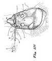
- an important aspect of the proceduregenerally is to isolate the pulmonary veins from the surrounding myocardium.
- the pulmonary veinsconnect the lungs to the left atrium of the heart, and join the left atrial wall on the posterior side of the heart.
- epicardial ablationmay be readily performed to create the requisite lesions for isolation of the pulmonary veins from the surrounding myocardium.
- Treatment of atrial ablation by open chest procedures, without performing other cardiac surgeries in tandem,has been limited by the substantial complexity and morbidity of the procedure.
- the location of the pulmonary veinscreates significant difficulties, as typically one or more lesions are required to be formed to completely encircle these veins.
- Instrumentsare removed from the right chest, and the right lung is re-inflated.
- the left lungis deflated, and a mirror reflection of the port pattern on the right chest is created through the left chest.
- the pericardium on the left sideis dissected to expose the left atrial appendage and the two catheters having been initially inserted from the right side are retrieved and pulled through one of the left side ports.
- the two catheter endsare then tied and/or sutured together and are reinserted through the same left side port and into the left chest.
- the leader of a Flex 10 microwave probe(Guidant Corporation, Santa Clara, Calif.) is sutured to the end of the upper catheter on the right hand side of the patient, and the lower catheter is pulled out of a right side port to pull the Flex 10 into the right chest and lead it around the pulmonary veins. Once in proper position, the Flex 10 is incrementally actuated to form a lesion around the pulmonary veins. The remaining catheter and Flex 10 are then pulled out of the chest and follow-up steps are carried out to close the ports in the patient and complete the surgery.
- a Flex 10 microwave probe(Guidant Corporation, Santa Clara, Calif.) is sutured to the end of the upper catheter on the right hand side of the patient, and the lower catheter is pulled out of a right side port to pull the Flex 10 into the right chest and lead it around the pulmonary veins.
- the Flex 10is incrementally actuated to form a lesion around the pulmonary veins.
- the remaining catheter and Flex 10are then pulled out of the chest and follow-up steps
- Apparatus, devices tools and methods for performing endoscopic surgical proceduresare provided where only a minimal number of (or even one) openings are required to perform the procedures.
- Ablation procedures, including epicardial ablation procedures and apparatus for performing such proceduresare described.
- Epicardial atrial ablationmay be performed epicardially with access through only one side of a patient's chest required to perform all procedures.
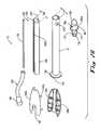
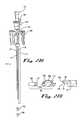
- Surgical device for performing minimally invasive surgical proceduresincluding an elongated body having distal and proximal end portions and at least two lumens extending generally along a direction of a longitudinal axis of the elongated body; and a distal tip attachable to the distal end portion of the elongated body, the distal tip including a lens that is viewable therethrough and aligned with one of the at least two lumens that is configured for receiving an endoscope therein.
- a handleis attached to the proximal end portion of the elongated body.
- a bellis rotatably attached to the handle.
- the elongated bodyis substantially rigid.
- At least one of the at least two lumens other than the lumen configured for receiving an endoscope thereincomprises a service port adapted to receive a tool other than an endoscope. In at least one embodiment, two such service ports are provided.
- each service port providedcomprises a tube received within the elongated body of the device.
- each tube extending from a service portcomprises a stainless steel hypotube.
- an endoscopeis positioned in the lumen that is configured for receiving an endoscope therein.
- the distal tip of the devicecomprises at least one lumen therethrough, wherein each lumens of the tip is configured and dimensioned to receive one of the tubes therein and provide an exit opening for a service port through the tip.
- a sealis provided between the lens and a portion of the tip proximal to the lens.
- a proximal end portion of each tubeis securely held by a handle attached to the proximal end portion of the elongated body.
- the lensis removably mounted to a remainder of the distal tip via mechanical connection.
- the lensis removably mounted to the remainder of the distal tip via at least one of friction fitting and threads.
- the lensis fixed to a remainder of the distal tip via adhesive.
- the distal tipis fixable to a distal end piece that includes at least one lumen, wherein the distal end piece is mountable to the distal end portion of the elongated body, and wherein the at least one lumen of the distal end piece aligns in communication with respective ones of at least one of the at least two lumens of the elongated body, in fluid communication therewith, to function as at least one service port.
- a protrusionextends distally from a distal end of the distal tip.
- a snare deviceextends through one of the at least two lumens, and the snare device includes a snare on a distal end thereof.
- the snare devicefurther comprises a snare on a proximal end thereof.
- a handle provided on the proximal end portion of the devicecomprises an open proximal end configured to receive an endoscope therethrough.
- the handlecaptures the proximal end portion of the elongated body, thereby preventing axial movement of the elongated body with respect to the handle.
- the handleallows rotation of the elongated body with respect thereto.
- the handleprevents rotation of the elongated body with respect thereto.
- a recessis provided in a portion of the handle, wherein the recess is configured and dimensioned to receive a light cable that extends from an endoscope, when the endoscope is received in the elongated body.
- an insertis mounted within the elongated body, wherein the insert and the elongated body cooperate to define the at least two lumens.
- the insertforms a friction fit with the elongated body within said elongated body.
- a second insertcan be provided to be interchanged with the first insert, wherein the second insert and the elongated body cooperate to form lumens having at least one of: a different size, different relative positioning and different number of lumens relative to size, positioning and number of the at least two lumens formed in cooperation between the elongated main body and the first insert.
- a second tipis provided that is interchangeable with the first tip, the second tip comprising at least one of: a different size, different relative positioning and different number of lumens relative to size, positioning and number of the at least one lumen formed in the first tip.
- the distal tipis axially aligned with the lumen that is configured for receiving the endoscope therein, and at least one of the at least two lumens that is not configured for receiving the endoscope therein is positioned radially outwardly from the lumen that is configured to receive the endoscope therein, such that an implement can be delivered though each lumen positioned radially outward, and a distal end portion of the implement is deliverable alongside the tip.
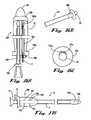
- the distal tipcomprises a ball-ended tip.
- the distal tipis bullet shaped.
- the distal tipcomprises a notch configured and dimensioned to receive a portion of a snare therein.
- a suction lueris provided in fluid communication with one of the at least two lumens, wherein the suction luer extends from the proximal end portion of the elongated body.
- an introducer tubeis provided in fluid communication with one of the at least two lumens, wherein the introduce tube extends from the proximal end portion of the elongated body.
- the elongated bodycomprises three lumens
- the devicefurther includes an introducer tube in fluid communication with a lumen other than the lumen configured and adapted to receive an endoscope and the lumen in fluid communication with the suction luer, wherein the introducer tube extends from the proximal end portion of the elongated body.
- the tip of the deviceis releasably attachable to the elongated body.
- the tipcomprises protrusions on a proximal end portion thereof, and the elongated body comprises openings through the walls of the distal end portion thereof, wherein the openings are configured and dimensioned to receive the protrusions.
- a suction tubeextends through one of the at least two lumens and provides fluid communication between the distal and proximal end portions of the elongated body.
- a suction tubeextends through one of the at least two lumens and provides fluid communication between the distal tip and the proximal end portion of the elongated body.
- the tip of the deviceincludes an inner stop configured to prevent distal advancement of a distal end of the endoscope therepast, to establish an offset between a distal end of the distal tip and the distal end of the endoscope.
- a cageis mounted to the distal tip to extend distally therefrom.
- the lens of the distal tipcomprises an outer lens, and the distal tip further includes an inner tapered lens configured to break up reflections when viewing through the endoscope.
- the distal end portion of the elongated bodyhas a first cross-sectional area and the proximal end portion of the elongated body has a second cross-sectional area, wherein the second cross-sectional area is greater than the first cross-sectional area.
- the distal end portion of the elongated bodyis teardrop-shaped in cross-section.
- the proximal end portion of the elongated bodyis circular in cross-section.
- the lumensare formed by metal tubes within the elongated tubular body.
- the distal tip of the devicecomprises at least one inflatable member mounted to a proximal end portion thereof.
- a snare capture toolextends through one of the at least two lumens, and has a ball-shaped distal end.
- a retrieval hook toolextends through one of the at least two lumens, and has a hook at a distal end thereof.
- a bolo toolextends through one of the at least two lumens, and has a ball at a distal end thereof. In at least one embodiment, the bolo tool also has a ball at a proximal end thereof.
- a trigger snare toolextends through one of the at least two lumens, the trigger snare tool comprising a snare at a distal end thereof that is extendable distally from the distal end portion of the elongated body, and a trigger configured to actuate the snare, wherein the trigger is located proximally of the proximal end portion of the elongated body.
- the snare of the trigger snare toolis angled relative to a longitudinal axis of the trigger snare tool.
- a perforation toolextends through one of the at least two lumens, and the perforation tool includes a needle or barbed needle at a distal end thereof, wherein the needle or barbed needle is extendable distally of the distal end portion of the elongated body.
- the perforation toolfurther includes a cutter blade, wherein the barbed needle is retractable proximally to draw tissue engaged by the barb needle into contact with the cutter blade.
- a perforation toolextends through one of the at least two lumens, wherein the perforation tool comprises graspers adapted to be extended distally to grasp tissue, and a cutter blade, and wherein the graspers are retractable proximally to draw tissue engaged by the graspers into contact with the cutter blade.
- a perforation toolextends through one of the at least two lumens, and the perforation tool includes a cork screw adapted to be extended distally to engage tissue, and a cutter blade, wherein the corkscrew is retractable proximally to draw tissue engaged by the corkscrew into contact with the cutter blade.
- a perforation toolextends through one of the at least two lumens, and the perforation tool comprises a spike configured to pierce through tissue upon an impulsive impact, and a plunger type actuator located on a proximal end portion of the perforation tool.
- a mapping probe toolextends through one of the at least two lumens of the device, and the mapping probe tool includes at least a pair of mapping elements on a distal end portion thereof, wherein the mapping elements are extendable distally of a distal opening of the lumen.
- the distal end portion of the mapping probe toolis bent at an angle to a longitudinal axis of a remainder of the mapping probe tool when the mapping probe tool is in an unbiased state.
- the distal end portion of the mapping probe toolis formed in a Y-shape when in an unbiased state, one of the mapping elements being located on one arm of the Y-shape and a second of the mapping elements being located on an arm opposite the one arm.
- a linear ablating probe toolextends through one of the at least two lumens, the linear ablating probe tool comprising a linear ablation element on a distal end portion thereof.
- a point ablation probe toolextends through one of the at least two lumens, the point ablation probe tool comprising an ablation probe point on a distal tip thereof.
- a cautery toolextends through one of the at least two lumens, the cautery tool comprising a cauterizing element on a distal end portion thereof.
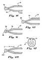
- graspersextend through one of the at least two lumens, and the graspers include a tube having sufficient length to simultaneously extend from both distal and proximal openings of the lumen, grasping jaws provided at a distal end portion of the graspers, and an actuator located at a proximal end portion of the graspers, wherein the actuator is linked to the grasping jaws for operation thereof.
- scissorsextend through one of the at least two lumens, wherein the scissors include a tube having sufficient length to simultaneously extend from both distal and proximal openings of the lumen, scissor jaws provided at a distal end portion of the scissors, and an actuator located at a proximal end portion of the scissors, and wherein the actuator is linked to the scissor jaws for operation thereof.
- the devicefurther includes an inflatable member that is expandable around a base of the distal tip to achieve a temporary, atraumatic increase in diameter at a distal end portion of the device.
- a fitting plugis positioned over the elongated body and fixed to the inflatable member for holding the inflatable member in position over the base of the distal tip.
- a tensioning memberinterconnects the fitting plug and the inflatable member, and the tensioning member is adjustable to draw the inflatable member into a desired position at the base of the distal tip.
- the lumen of the device that is configured for receiving an endoscope thereincomprises a positioning feature for positioning the endoscope at more than one predetermined location.
- the positioning featurecomprises biased sockets configured to receive protrusions on the endoscope therein.
- the distal tip of the deviceincludes at least one window proximal of a distal end of the distal tip, through which viewing by the endoscope is permitted.
- a handle of the deviceincludes proximal and distal stops so that when the endoscope is inserted in the lumen that is configured for receiving an endoscope therein, a light cable of the endoscope abuts the proximal stop for placing the endoscope in one predetermined location relative to the elongated body, and abuts the distal stop for placing the endoscope in a second location relative to the elongated body.
- a surgical device for performing minimally invasive surgical proceduresincluding: a first elongated body having distal and proximal end portions and at least one lumen extending generally along a direction of a longitudinal axis of the first elongated body and configured and dimensioned for receiving an endoscope therein; a second elongated body aligned substantially parallel with the first elongated body, the second elongated body having distal and proximal end portions and at least one lumen extending generally along a direction of a longitudinal axis of the second elongated body and configured and dimensioned for receiving a tool other than the endoscope therein; and a distal tip attachable to the distal end portion of the first elongated body, wherein the distal tip includes a lens that is viewable therethrough and aligned with the lumen that is configured and dimensioned for receiving an endoscope therein.
- an endoscopeis positioned in the lumen that is configured and dimensioned for receiving an end
- a handleis attached to the proximal end portion of the first elongated body.
- the first and second elongated bodiesare substantially rigid.
- the second elongated bodyis fixed externally to the first elongated body. In at least one embodiment, the second elongated body is welded to the first elongated body.
- a snare deviceextends through one of the at least one lumen of the second elongated body, wherein the snare device has a snare on a distal end thereof. In at least one embodiment, the snare device further includes a snare on a proximal end thereof.
- the distal tipis attached to the distal end portion of the first elongated body, and a distal end of the endoscope is positioned within the distal tip.
- the distal tipcomprises a ball-ended tip.
- the distal tipis bullet shaped.
- the distal tipcomprises a notch configured and dimensioned to receive a portion of a snare therein.
- a tool other than an endoscopeextends through one of the at least one lumens of the second elongated body.
- the toolis selected from the group consisting of: suction tool, snare capture tool, retrieval hook tool, bolo tool, trigger snare tool, perforation tool, mapping probe tool, linear ablating probe tool, point ablation probe tool, cautery tool, graspers tool, and scissors tool.
- a surgical device for performing minimally invasive surgical proceduresincluding: an elongated body having distal and proximal end portions and at least two lumens extending generally along a direction of a longitudinal axis of the elongated body; and an endoscope positioned in one of the at least two lumens that is configured and dimensioned for receiving the endoscope therein; wherein a distal end of the elongated body extends distally past a distal end of the endoscope to shield the distal end of the endoscope during use.
- the distal end of the elongated bodyis open.
- one of the at least one lumenscomprises an irrigation lumen.
- a nozzleis provided at a distal end of the irrigation lumen.
- the nozzleis oriented toward the distal end of the endoscope.
- the nozzleis located out of a field of view of the endoscope.
- the distal end portion of the elongated bodyis transparent to allow visualization therethrough.
- a snare deviceextends through one of the at least two lumens of the elongated body, the snare device having a snare on a distal end thereof. In at least one embodiment, the snare device further comprises a snare on a proximal end thereof.
- a surgical device for performing minimally invasive surgical proceduresincluding: an elongated body comprising a semi-flexible sleeve having distal and proximal end portions and at least one lumen extending generally along a direction of a longitudinal axis of said elongated body; and
- a rigid distal tipattached to a distal end of said elongated body, said distal tip being viewable therethrough.
- the sleeveis sufficiently flexible to navigate around pulmonary veins to at least partially encircle the pulmonary veins and the sleeve is sufficiently rigid so that a proximal portion of the sleeve outside of a patient can be pushed on to advance the distal end portion of the sleeve within the patient.
- an endoscopeis inserted in the sleeve, the endoscope having a rigid shaft and being positioned for viewing through the distal tip.
- the distal tipcomprises a ball at a distal end thereof.
- the distal tipcomprises at least one port in fluid communication with the at least one lumen in the elongated body.
- a surgical device for performing minimally invasive surgical proceduresincluding: an elongated body comprising a semi-flexible sleeve having distal and proximal end portions; and
- a capturing featureextending distally from a distal end of said elongated body.
- an endoscopeis inserted in the sleeve, wherein the endoscope has a distal tip attached thereto that extends distally of the distal end of the elongated body.
- the capturing featurecomprises a snare threaded through openings in the distal tip to extend distally therefrom.
- the elongated bodyis slidable proximally with respect to the distal tip to cinch down the snare.
- the capturing featurecomprises a pad of either a hook or a loop portion of a hook and loop type fastening mechanism.
- the capturing featurecomprises a magnet
- a surgical device for performing minimally invasive surgical proceduresincluding: an elongated body having distal and proximal end portions and at least two lumens extending generally along a direction of a longitudinal axis of the elongated body, wherein at least one of the lumens comprises a slot opening to an external surface of the elongated body, and the slot is configured and dimensioned to releasably secure a tool therein via friction fit.
- the toolcomprises a snare catheter.
- a distal tipattachable to the distal end portion of the elongated body, wherein the distal tip includes a lens that is viewable therethrough and aligned with one of the at least two lumens that is configured for receiving an endoscope therein.
- the slotextends over a majority of a length of the elongated body.
- the slotis formed in an eyelet on the distal end portion of the elongated body.
- the toolincludes a distal end portion having a first outside diameter larger than an outside diameter of a portion of the tool immediately proximal of the distal end portion of the tool, wherein the portion immediately proximal is slidable through the slot, and wherein retraction of the tool being positioned through the slot and into the lumen that the slot opens to, secures the distal end portion in the eyelet.
- the slotis formed by a keyed socket on the distal end portion of the elongated member.
- the at least one lumen having a slotis asymmetrical in cross-section and forms a cam surface permitting the tool to be rotated into the at least one lumen having a slot.
- a surgical device for performing minimally invasive surgical proceduresincluding: an endoscope having an elongated shaft having distal and proximal end portions; a distal tip attachable to the distal end portion of the endoscope, the distal tip including a lens that is viewable therethrough; and a ring provided over the elongated shaft and axially slidable with respect thereto, the ring being configured and dimensioned to releasably fix a distal end portion of a tool thereto.
- the ringcomprises a releasable locking mechanism.
- the toolcomprises a snare catheter.
- a surgical device for performing minimally invasive surgical proceduresincluding: a jig having slots configured and dimensioned to receive and releasably fix an endoscope and at least one tool thereto for rapid exchange procedures.
- a pair of such jigs each configured with the slotsis provided.
- an endoscope and a snare catheterare each releasably fixed to the jig.
- a surgical device for performing minimally invasive surgical proceduresincluding: a jig having at least one opening configured and dimensioned to receive and releasably fix a tool thereto for rapid exchange procedures; and an opening configured and dimensioned to receive an endoscope therethrough, wherein the endoscope is freely slidable with respect to the jig.
- a pair of such jigsare provided.
- each jigcomprises at least two openings for releasably fixing at least two tools.
- an endoscopeis slidably received within the jig, and a snare catheter is releasably fixed to the jig.
- an endoscopeis slidably received within the jig, a snare catheter is releasably fixed to the jig, and a second tool is releasably fixed to the jig.
- the second toolcomprises a suction tube.
- a surgical device for performing minimally invasive surgical proceduresincluding: an elongated body having distal and proximal end portions and configured and dimensioned to receive an endoscope therethrough and to apply suction therethrough; and a distal tip attachable to the distal end portion of the elongated body, the distal tip including a lens that is viewable therethrough, the distal tip having a proximal opening having an outside diameter that is greater than an outside diameter of a distal end of the elongated body, such that a gap is formed between the distal tip and the elongated body when the distal tip is attached to the elongated body, facilitating diffuse application of suction.
- strutsinterconnect the distal tip and the elongated body.
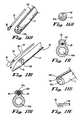
- a routing snare toolconfigured and dimensioned to be slid through a lumen of a device that also receives an endoscope is provided, including: a flexible outer tube having sufficient column strength to advance the tool through the lumen by pushing on a proximal portion of the outer tube from a location outside of the lumen, to advance the tube without buckling; a snare line having a length greater than a length of the flexible outer tube; and a snare loop fixed to an end of the snare line via heat shrink tubing.
- a second snare loopis fixed to an opposite end of the snare line via heat shrink tubing.
- both ends of the outer tubeare chamfered.
- the heat shrink tubingis color coded differently with respect to each snare loop to facilitate ready visual distinction between the two snare loops.
- the snare loopcomprises a kink extending distally from a remainder of the snare loop.
- the snare loopis angled, with respect to a longitudinal axis of the snare line, by an angle of less than about thirty degrees.
- a lockis configured to fix a position of the snare line relative to the outer tube to maintain the snare loop in a cinched configuration.
- the lockcomprises an actuator configured to move a clamp into contact with the snare line.
- the lockcomprises a pair of locking clasps that are alternatively lockable and releasable by the same actuating movement by a user.
- a snare capture toolconfigured and dimensioned to be slid through a lumen of a device that also receives an endoscope
- an endoscopeincluding: an elongated mandrel configured and dimensioned to be slid through the lumen; a handle fixed to a proximal end of the mandrel; and a ball fixed at a distal end of the mandrel.
- a polymeric layeris formed over a majority of the mandrel, wherein a distal end portion of the mandrel extends from a distal end of the polymeric layer and is not covered thereby.
- a compressible springis provided over the polymeric layer, a proximal end portion of the spring abuts the handle, and the spring has a outside diameter larger than an inside diameter of the lumen, thereby being prevented from insertion into the lumen.
- the snare capture toolis configured and dimensioned, so that when the spring is compressed against a proximal end of the lumen by advancing the handle distally with respect to the lumen, the ball and at least a portion of the distal portion not covered by the polymeric layer extend distally from a distal end of the lumen, and when a driving force is released from the handle, the spring expands, thereby retracting the ball and the at least a portion of the distal portion not covered by the polymeric layer, into the lumen.
- a retrieval hook toolconfigured and dimensioned to be slid through a lumen of a device that also receives an endoscope is provided, including: an elongated mandrel configured and dimensioned to be slid through the lumen; a handle fixed to a proximal end of the mandrel; and a hook provided at a distal end of the mandrel.
- a polymeric layeris formed over a majority of the mandrel, wherein a distal end portion of the mandrel extends from a distal end of the polymeric layer and is not covered thereby.
- a compressible springis provided over the mandrel, a proximal end portion of the spring abutting said handle, said spring having a outside diameter larger than an inside diameter of said lumen, thereby being prevented from insertion into said lumen.
- the retrieval hook toolis configured and dimensioned, so that when the spring is compressed against a proximal end of the lumen by advancing the handle distally with respect to the lumen, the hook extends distally from a distal end of the lumen, and when a driving force is released from the handle, the spring expands, thereby retracting the hook into the lumen.
- the mandrelis offset in the polymeric layer, such that longitudinal axes of the mandrel and the polymeric layer do not coincide.
- a bolo toolconfigured and dimensioned to be slid through a lumen of a device that also receives an endoscope is provided, including: an elongated mandrel configured and dimensioned to be slid through the lumen; a first ball provided at a proximal end of the mandrel; and a second ball provided at a distal end of the mandrel.
- a trigger snare tool and dimensioned to be slid through a lumen of a device that also receives an endoscopeincluding: an elongated mandrel configured and dimensioned to be slid through the lumen; a snare provided at a distal end of the mandrel; and a snare guide into which the elongated mandrel is slidably received, the snare guide being configured and dimensioned to be slid through the lumen, wherein the snare guide is slidable distally with respect to the mandrel to cinch down the snare.
- a handleis provided at a proximal end of the mandrel; a trigger is slidably positioned over the handle and fixed to a proximal end of the snare guide; and a biasing member is provided that biases the trigger distally from the handle.
- the snarewhen uncinched, is oriented at an acute angle with respect to a longitudinal axis of the mandrel.
- a perforation toolconfigured and dimensioned to be slid through a lumen of a device that also receives an endoscope
- a perforating memberconnected to an actuator via an elongated shaft
- a sheathconfigured and dimensioned to be slid through the lumen of the device and to surround the perforating member and the shaft during sliding within the lumen
- the actuatoris operable to slide the perforating member distally with respect to the sheath to extend the perforating member distally beyond a distal end of the sheath.
- the perforating membercomprises a needle.
- the perforating membercomprises a spike.
- the perforation toolincludes a handle mounted to a proximal portion of the tool, the handle being configured to be mated with a connector of a suction assembly.
- a cutting bladeis positioned proximally of the perforating member, and the perforating member is configured to engage tissue, wherein the actuator is actuatable to retract the perforating member, after engaging tissue, to draw the tissue against the cutting blade, thereby cutting an opening through the tissue.
- a second actuatoris provided, wherein the second actuator is linked to the cutting blade and is operable to rotate the cutting blade.
- the perforating membercomprises a barbed needle.
- the perforating membercomprises a corkscrew.
- the perforating membercomprises graspers.
- the actuatoris further actuatable to open and close the graspers.
- a mapping probe toolconfigured and dimensioned to be slid through a lumen of a device that also receives an endoscope
- an elongated memberconfigured and dimensioned to be positioned in the lumen and having a length sufficient to extend a proximal end portion of the elongated member from the proximal end of the lumen while a distal end portion extends distally from a distal end of the lumen; wherein the distal end portion includes at least a pair of probe mapping elements, and the probe mapping elements are electrically connectable to a power source located proximally of the tool via at least one electrical wire connected thereto.
- a handleis fixed to a proximal end portion of the elongated member; and a biasing member is configured to bias the handle away from the lumen, the biasing member being configured and dimensioned to prevent insertion of the biasing member into the lumen.
- the mapping toolis configured and dimensioned, so that when the handle is slid distally with respect to the lumen, thereby biasing the biasing member, the probe mapping elements extend distally from a distal end of the lumen, and when a driving force is released from the handle, the biasing member drives the handle proximally with respect to the lumen, thereby retracting the probe mapping elements into the lumen.
- the distal end portionis Y-shaped in an unbiased configuration, with one of each pair of probes being located on opposite ones of open arms of the Y-shape.
- the distal end portionis angled to a longitudinal axis of a remainder of the elongated member when the elongated member is in an unbiased configuration.
- a linear ablating probe toolconfigured and dimensioned to be slid through a lumen of a device that also receives an endoscope
- an elongated memberconfigured and dimensioned to be positioned in the lumen and having a length sufficient to extend a proximal end portion of the elongated member from the proximal end of the lumen while a distal end portion extends distally from a distal end of the lumen; a linear ablation member located at the distal end portion of the elongated member and configured to form a linearly extending lesion in tissue being treated thereby; and at least one ablation conduit connected to the linear ablation member and extending from the linear ablation member to a proximal end portion of the elongated member, a proximal end of each ablation conduit being configured to be connected to a source of ablation energy located proximally of the tool.
- an actuatoris located on the proximal end portion of the elongated member, the actuator being operable by a user to deliver ablation energy to the linear ablation member.
- a handleis fixed to a proximal end portion of the elongated member; and a biasing member is configured to bias the handle away from the lumen, the biasing member being configured and dimensioned to prevent insertion of the biasing member into the lumen.
- the linear ablating toolis configured and dimensioned, so that when the handle is slid distally with respect to the lumen, thereby biasing the biasing member, the linear ablation member extends distally from a distal end of the lumen, and when a driving force is released from the handle, the biasing member drives the handle proximally with respect to the lumen, thereby retracting the linear ablation member into the lumen.
- a point ablation probe toolconfigured and dimensioned to be slid through a lumen of a device that also receives an endoscope
- an elongated memberconfigured and dimensioned to be positioned in the lumen and having a length sufficient to extend a proximal end portion of the elongated member from the proximal end of the lumen while a distal end portion extends distally from a distal end of the lumen; an ablation probe point provided on a distal end of the elongated member and configured to form a point lesion in tissue being treated thereby; and an ablation conduit connected to the ablation probe point and extending from the ablation probe point to a proximal end portion of the elongated member, a proximal end of the ablation conduit being configured to be connected to a source of ablation energy located proximally of the tool.
- an actuatoris located on the proximal end portion of the elongated member, the actuator being operable by a user to deliver ablation energy to the ablation probe point.
- a handleis fixed to a proximal end portion of the elongated member; and a biasing member is configured to bias the handle away from the lumen, the biasing member being configured and dimensioned to prevent insertion of the biasing member into the lumen.
- the point ablation probe toolis configured and dimensioned, so that when the handle is slid distally with respect to the lumen, thereby biasing the biasing member, the ablation probe point extends distally from a distal end of the lumen, and when a driving force is released from the handle, the biasing member drives the handle proximally with respect to the lumen, thereby retracting the ablation probe point into the lumen.
- a cautery toolconfigured and dimensioned to be slid through a lumen of a device that also receives an endoscope
- an elongated memberconfigured and dimensioned to be positioned in the lumen and having a length sufficient to extend a proximal end portion of the elongated member from the proximal end of the lumen while a distal end portion extends distally from a distal end of the lumen; a cauterizing element provided on a distal end of the elongated member and configured to cauterize tissue; and an electrical wire connected to the cauterizing element and extending from the cauterizing element to a proximal end portion of the elongated member, a proximal end of the electrical wire being configured to be connected to a power source located proximally of the tool.
- an actuatoris located on the proximal end portion of the elongated member, the actuator being operable by a user to deliver energy to the cauterizing element.
- a handleis fixed to a proximal end portion of the elongated member; and a biasing member is configured to bias the handle away from the lumen, the biasing member being configured and dimensioned to prevent insertion of the biasing member into the lumen.
- the cautery toolis configured and dimensioned, so that when the handle is slid distally with respect to the lumen, thereby biasing the biasing member, the cauterizing element extends distally from a distal end of the lumen, and when a driving force is released from the handle, the biasing member drives the handle proximally with respect to the lumen, thereby retracting the cauterizing element into the lumen.
- a graspers toolconfigured and dimensioned to be slid through a lumen of a device that also receives an endoscope
- grasping jawsconnected to an actuator via an elongated linkage
- a sheathconfigured and dimensioned to be slid through the lumen of the device and to surround the grasping jaws and the linkage during sliding within the lumen
- the actuatorbeing operable to slide the grasping jaws distally with respect to the sheath to extend the grasping jaws distally beyond a distal end of the sheath.
- the actuatoris further actuatable to open and close the grasping jaws.
- a scissors toolconfigured and dimensioned to be slid through a lumen of a device that also receives an endoscope
- the actuatoris further actuatable to open and close the scissors jaws.
- a minimally invasive method of routing a flexible tool around an internal structure in a patient's bodyincluding the steps of: inserting a device including an endoscope through a small opening in the patient and advancing the device to position a distal end of the device into a surgical space in which the internal structure resides; inserting the flexible member through a service port in the device and extending a distal end portion of the flexible member distally of a lumen joined by the service port; visually confirming positioning of the distal end portion via the endoscope; removing the device from the patient via the small opening while maintaining the flexible member in the patient, substantially in the current position of the flexible member; inserting the device through a second small opening in the patient and advancing the device to position the distal end of the device into the surgical space in which the internal structure resides, on a side of the internal structure opposite to the side in which the flexible member is placed; connecting the distal end of the device with the distal end portion of the flexible member; and removing the device from the patient via the second small opening,
- the methodfurther includes further comprising advancing the distal end of the flexible member partially around the internal structure after removing the device from the patient via the small opening while maintaining the flexible member in the patient, substantially in the current position of the flexible member.
- the methodincludes visualizing the distal end of the flexible member through the endoscope to align the device with the flexible member to perform the connecting step.
- the distal end of the flexible membercomprises a snare loop and the connecting step comprises cinching the snare loop over a distal end portion of the device.
- the methodincludes fixing an ablation device to the proximal end of the flexible member and further advancing the flexible member by drawing the flexible member out of the second opening, thereby routing the ablation device around the internal structure.
- the internal structurecomprises a plurality of pulmonary veins.
- the methodincludes ablating tissue along a pathway defined by the ablation device around the internal structure.
- the distal end of the flexible membercomprises a ball and the connecting step comprises inserting a retrieval hook tool through a service port of the device, extending a hook of the retrieval hook tool distally of a distal end of a lumen that is in fluid communication with the service port, and hooking the distal end portion of the flexible member with the hook.
- the distal end of the flexible membercomprises a snare loop and the connecting step comprises inserting a retrieval hook tool through a service port of the device, extending a hook of the retrieval hook tool distally of a distal end of a lumen that is in fluid communication with the service port, and hooking the snare loop with the hook.
- the distal end of the flexible membercomprises a ball and the connecting step comprises inserting a trigger snare tool through a service port of the device, extending a snare of the trigger snare tool distally of a distal end of a lumen that is in fluid communication with the service port, and snaring the distal end portion of the flexible member by cinching down the snare loop after placing the snare loop over the ball.
- a step of perforating at least one tissue layer to establish a pathway for the advancing stepis performed.
- the perforating stepcomprises inserting a perforating tool through a service port of the device, extending a perforating member distally of a distal end of a lumen that is in fluid communication with the service port and into contact with tissue to be perforated, and perforating the tissue.
- the perforating stepcomprises inserting a perforating tool through a service port of the device, extending a perforating member distally of a distal end of a lumen that is in fluid communication with the service port and into contact with tissue to be perforated, grasping the tissue and retracting the grasped tissue against a cutting blade, thereby perforating the tissue.
- the methodfurther includes reinserting the device into at least one of the first and second openings, advancing the distal end of the device toward the internal structure, and visually inspecting at least a portion of the lesion formed around the internal structure via the endoscope.
- the methodfurther includes reinserting the device into at least one of the first and second openings, advancing the distal end of the device toward the internal structure, inserting a mapping probe tool through a service port in the device, extending mapping probe elements distally of a distal opening of a lumen in fluid connection with the service port, contacting tissue on opposite sides of a lesion, formed by the ablating step, with at least one mapping probe on each side of the lesion, and measuring sufficiency of the lesion formed with the mapping probe tool.
- a minimally invasive method of routing a flexible tool around an internal structure in a patient's bodyincluding: inserting a device including an endoscope through a small opening in the patient and advancing the device to position a distal end of the device into a surgical space in which the internal structure resides; inserting the flexible member through a service port in the device and extending a distal end portion of the flexible member distally of a lumen joined by the service port; visually confirming the distal end portion via the endoscope; retracting the device to remove the flexible member from a distal end of the lumen, while maintaining the flexible member in the patient, substantially in the current position of the flexible member; distally advancing the device into patient to position the distal end of the device into the surgical space in which the internal structure resides, on a side of the internal structure opposite to the side in which the flexible member is placed; connecting the distal end of the device with the distal end portion of the flexible member; and removing the device from the patient via the small opening, thereby drawing the flexible member
- the methodfurther includes advancing the distal end of the flexible member partially around the internal structure after removing the flexible member from the device while maintaining the flexible member in the patient, substantially in the current position of the flexible member.
- the methodfurther includes fixing an ablation device to the proximal end of the flexible member and further advancing the flexible member by drawing the flexible member out of the opening, thereby routing the ablation device around the internal structure.
- the methodfurther includes ablating tissue along a pathway defined by the ablation device around the internal structure.
- a minimally invasive method of routing a flexible tool around an internal structure in a patient's bodyincluding the steps of: inserting a device including a semi-flexible sheath slid over an endoscope through a small opening in the patient and advancing the device to position a distal end of the device into a surgical space in which the internal structure resides, the semi-flexible sheath including a rigid, transparent distal end that allows viewing therethrough via the endoscope; visually confirming placement of the distal end of the semi-flexible member via the endoscope; removing the device endoscope from the patient via the small opening while maintaining the semi-flexible member and rigid distal end in the patient, substantially in the current position of the semi-flexible member and rigid distal end; inserting the endoscope through a second small opening in the patient and advancing the endoscope to position the distal end thereof into the surgical space in which the internal structure resides, on a side of the internal structure opposite to the side in which the semi-flexible member is placed; connecting the
- the methodfurther includes advancing the distal end of the semi-flexible member partially around the internal structure after the removal of the endoscope from the patient via the small opening while maintaining the semi-flexible member in the patient, substantially in the current position of the flexible member.
- the methodfurther includes visualizing the distal end of the flexible member through the endoscope to align the device with the flexible member to perform the connecting step.
- the methodfurther includes sliding a sleeve having a distal tip over the endoscope prior to inserting the endoscope through a second small opening.
- the sleevecomprises a snare loop extending from the distal tip, the snare loop being threaded through a distal tip and the distal tip being mounted to the endoscope.
- the connecting stepcomprises cinching the snare loop around the distal end of the semi-flexible member.
- the cinchingis performed by sliding the sleeve proximally with respect to the endoscope.
- the methodfurther includes fixing an ablation device to the proximal end of the semi-flexible member and further advancing the semi-flexible member by drawing the semi-flexible member out of the second opening, thereby routing the ablation device around the internal structure.
- the methodfurther includes ablating tissue along a pathway defined by the ablation device around the internal structure.
- a method of performing rapid exchange of tools in a device while performing a minimally invasive surgical procedureincluding the steps of: inserting a device having at least and an endoscope and a first tool received therein, through a small opening in the patient and advancing the device to position a distal end of the device into a reduced-access surgical space; removing the first tool from the device, while maintaining the device and the endoscope in the surgical space; and inserting a second tool into the device, thereby replacing the tool having been removed.
- the removing stepcomprises removing the first tool through a slot opening to an external surface of the device from a lumen in the device.
- the first toolcomprises a snare catheter.
- the removing stepcomprises removing the first tool from an eyelet on a distal end portion of the device.
- the lumen from which the slot opensis asymmetrical in cross-section and forms a cam surface permitting the second tool to be rotated into the lumen.
- the devicecomprises a ring provided over an elongated shaft of the endoscope and axially slidable with respect thereto, and wherein the removing step comprises releasing the first tool from the ring.
- the devicecomprises a jig having slots configured and dimensioned to receive and releasably fix the endoscope and the first tool.
- the devicecomprises a pair of such jigs.
- the devicecomprises a jig having an opening configured and dimensioned to receive and releasably fix the first tool thereto for rapid exchange procedures; and an opening configured and dimensioned to receive the endoscope therethrough, wherein the endoscope is freely slidable with respect to the jig.
- a method of relieving side loading by an operating room suction tubing on a device in fluid communication with the operating room suction tubingincluding the steps of: providing a length of tubing having a lighter gauge than a gauge of the operating room suction tubing, the length of tubing having proximal and distal ends; connecting the distal end of the length of tubing to a suction assembly of a device to be used to apply suction; and connecting the proximal end of the length of tubing to the operating room suction tubing, thereby putting the suction assembly of the device in fluid communication with the operating room suction tubing.
- the methodfurther comprises clamping the length of tubing to a support.
- the length of tubingcomprises a tether extending therefrom, and the clamping step comprises clamping the tether to the support.
- the supportis a surgical drape.
- a tool for relieving side loading on a device in fluid communication with an operating room suction tubeincluding: a length of tubing having a lighter gauge than a gauge of the operating room suction tubing, the length of tubing having proximal and distal ends; a first connector at a distal end of the length of tubing configured and dimensioned to be connected to a suction assembly of the device, to establish fluid communication between the suction assembly and the length of tubing; a second connector at a proximal end of the length of tubing configured and dimensioned to be connected to the operating room suction tube, to establish fluid communication between the operating room suction tube and the length of tubing; and a tether extending from the length of tubing, the tether adapted to be clamped to a support.
- FIG. 1Ashows a dissecting instrument that may be used to carry out procedures during the performance of methods described herein.
- FIG. 1Bshows an optional tapered or conical transparent tip mounted concentrically with respect to the endoscope and tip 20 and within tip 20 of FIG. 1A .
- FIG. 2Ashows another example of an instrument useful for performing procedures described herein.
- FIG. 2Bis an exploded view of the device shown in FIG. 2A .
- FIG. 2Cis a plan view of a device, similar to that shown in FIG. 2A , but having a dissecting tip.
- FIG. 2Dis an exploded view of a device that is similar to device shown in FIG. 2A , configured for routing an implement along a navigational course in a reduced access surgical environment.
- FIG. 2Eis a plan view of a device, similar to that shown in FIG. 2A , but having a ball tip.
- FIG. 3Ashows an assembled view of a device with an endoscope inserted.
- FIG. 3Bshows an exploded view of the arrangement shown in FIG. 3A .
- FIGS. 4A and 4Bshow an end view and longitudinal sectional view of a tip configured as an atraumatic viewing tip that offsets tissue from the endoscope lens by an offset distance.
- FIG. 4Cshows one example of a tip having a different offset length than that of the example of FIG. 4B .
- FIG. 4Dshows a tip provided with a cage.
- FIG. 4Eshows another modification of a tip in which the distal surface has a parabolic profile or “bullet tip”.
- FIGS. 4F and 4Gshow tips which differ in configuration by the thickness of the lens at the distal end portion of the tip.
- FIG. 4Hshows a tip that is further provided with openings that communicate with lumens in a device to which the tip is connected.
- FIG. 4Iis a sectional view of the tip of FIG. 4H .
- FIG. 4Jis a distal end view of the tip of FIG. 4H .
- FIG. 4Kshows a ball ended tip that may be used for routing an implement along a navigational course in a reduced access surgical environment, and/or for retrieving an implement already having been so routed.
- FIG. 4Lshows a variation of the tip shown in FIG. 4K , in which a slot, groove, notch or other securement feature is provided at the proximal end portion of the ball.
- FIG. 4Mshows a tip similar to that of FIG. 4K and in which a similar offset has been designed and in which the distal end portion of the lens has varied thickness.
- FIGS. 4N and 4Oshow sectional and distal end views of a variation of a ball-ended tip that includes openings configured to communicate with lumens in a device to which it is attachable.
- FIGS. 4P-4Sshow various tips that are adapted to facilitate dissection when connected to a device and inserted into a surgical space.
- FIGS. 5A , 5 B and 5 Cshow a viewing tip, ball-ended tip and dissecting tip, respectively.
- FIGS. 6A-6Nshow alternative arrangements for forming multiple lumens within a tube.
- FIG. 6Ois a partial, exploded view of a device showing a proximal end portion of a distal tip configured to function as a bracket to maintain a distal position of an inner tube relative to an outer tube.
- FIG. 6Pshows an example where a handle of the device functions as a bracket to maintain proximal end portions of inner in position relative to the outer tube.
- FIG. 7Ais a perspective view of a handle employable in at least one device embodiment described herein.
- FIGS. 7B and 7Cshow opposite handle haves of the handle shown in FIG. 7A .
- FIG. 8Ais a perspective view of a variation of a handle employable in at least one device embodiment described herein.
- FIGS. 8B and 8Cshow opposite handle haves of the handle shown in FIG. 8A .
- FIG. 9Aillustrates a tip having threads provided at a proximal end portion thereof.
- FIG. 9Billustrates another tip having threads provided at a proximal end portion thereof.
- FIG. 9Cshows an arrangement in which a tip is provided with a quick release mechanism.
- FIG. 10Ashows an embodiment of a snare catheter that may be inserted into a tube or lumen for routing to a desired surgical location in a reduced-access surgical site.
- FIG. 10Bshows an embodiment of a snare catheter having a preconfigured bend in its distal section when in an unstressed state.
- FIGS. 11A and 11Billustrated a partial view and sectional view of the distal end of another arrangement of an endoscope and tube, in which no tip is used.
- FIG. 12Aillustrates a cutaway anterior view of a human heart with an instrument being used to penetrate the pericardial reflection.
- FIG. 12Bshows advancement of a snare loop to pass superiorly over the left pulmonary veins, around the left pulmonary veins and into the oblique pericardial sinus.
- FIG. 12Cshows an instrument having been inserted into the oblique sinus via a small opening in the patient.
- FIG. 12Dshows an ablation device fixed to the proximal end of a member having been routed around the pulmonary veins.
- FIGS. 13B-13Cshow sliding the flexible device over a catheter for use in a procedure as described above with regard to FIG. 13A .
- FIG. 14illustrates one example of a lock, wherein an actuator is provided to be slid or rotated by an operator to tighten or loosen a clamp against a snare line.
- FIG. 15illustrates an alternative locking mechanism that includes a four bar linkage.
- FIG. 16A-16Billustrate a partial perspective view and cross-sectional view of an alternative arrangement for releasing a snare catheter from a device.
- FIGS. 17A-17Cillustrate another alternative arrangement for releasing a snare catheter from an instrument/device.
- FIGS. 18A , 18 B and 18 Cillustrate a released view, a captured view, and a cross-sectional view of the captured view of another quick release arrangement allows a snare catheter to be rapidly separated from a device.
- FIG. 19illustrates an arrangement where a ring or sleeve is provided over the shaft of an endoscope so as to be freely slidable with respect thereto, and a snare catheter is releasably fixable to the ring or sleeve.
- FIG. 20Aillustrates another arrangement, wherein one or more jigs are provided through which a snare catheter or other tube or tool, and endoscope are passed.
- FIG. 20Bis a perspective view of one of the jigs shown in FIG. 20A .
- FIG. 20Cshows the assembly of FIG. 20C without the endoscope.
- FIGS. 21A-21Billustrate a plan view and sectional view of a jig, wherein lumens formed in the jig are provided with slots or gaps that allow a snare catheter and/or other tools, and endoscope to be snapped in and out for rapid exchange.
- FIG. 22illustrates a modification of a connection of a tip to a device that allows diffuse suction to be applied.
- FIG. 23Ashows an exploded view of another example of a device in accordance with an embodiment of the present invention.
- FIG. 23Bis a partial, exploded view of the distal end portion of the device shown in FIG. 23A .
- FIG. 23Cis a partial, exploded view of the proximal end portion of the device shown in FIG. 23A .
- FIG. 24Aillustrates another example of a snare catheter, which is also referred to as a “routing snare” tool.
- FIG. 24Bshows distal and proximal end portions of the snare routing tool shown in FIG. 24A .
- FIG. 25Ashows a snare capture tool
- FIG. 25Bis an enlarged view of the proximal end portion of the snare capture tool shown in FIG. 25A .
- FIG. 25Cis an enlarged view of the distal end portion of the snare capture tool shown in FIG. 25A .
- FIG. 26Ashows an elongated retrieval hook tool configured and dimensioned to be slid though a lumen of a device described herein.
- FIG. 26Billustrates the tool shown in FIG. 26A in use.
- FIG. 26Cillustrates a partial view of a hook tool in an alternative configuration.
- FIG. 27Aillustrates a bolo tool that may be used in place of a snare assembly for routing an ablation device around the pulmonary veins.
- FIG. 27Bshows a retrieval tool that may be used to retrieve the bolo tool shown in FIG. 27A .
- FIG. 27Cillustrates a distal end portion of a retrieval tool.
- FIG. 28Aillustrates a perforation tool that may be used to perforate the pericardial sac prior to introduction of a device therethrough.
- FIG. 28Bshows an alternative arrangement of a perforation tool in which graspers are provided to grasp the pericardial tissue, to draw it back against a cutter blade to form an opening in the pericardial tissue.
- FIG. 28Cshows another alternative arrangement of a perforation tool, wherein the grasping implement provided in this example is a cork screw configuration, which can be screwed into the pericardial tissue to grasp or secure it, to draw it back against a cutter blade.
- the grasping implement provided in this exampleis a cork screw configuration, which can be screwed into the pericardial tissue to grasp or secure it, to draw it back against a cutter blade.
- FIG. 28Dshows another alternative arrangement of a perforation tool that may be used to form an opening in the pericardial tissue and/or used for dissection through the pericardial reflections.
- FIG. 28Eshows still another alternative arrangement of a perforation tool that may be used to form an opening in the pericardial tissue and/or used for dissection through the pericardial reflections.
- FIG. 29Aillustrates a partial view of a mapping probe tool that may be used in a device described herein.
- FIG. 29Bshows a variation of the tool of FIG. 29A .
- FIG. 29Cshows another variation of the tool of FIG. 29A .
- FIG. 30illustrates a partial view of a linear ablating probe tool that may be used in a device described herein.
- FIG. 31illustrates a distal end portion of a point/disk ablation probe tool that may be used in a device described herein.
- FIG. 32illustrates a distal end portion of a monopolar cautery tool that may be used in a device described herein.
- FIG. 33illustrates graspers that may be used in a device described herein.
- FIG. 34illustrates scissors that may be used in a device described herein.
- FIG. 35Aillustrates an arrangement for minimizing side loading on a suction assembly during use with a device described herein, when the suction assembly is connected to a suction source.
- FIG. 35Billustrates an example of suction tube management wherein an extension tubing is in fluid communication with a suction assembly provided in a device that is configured to be used in surgical site.
- FIG. 35Cillustrates a tether that is clamped to a surgical drape to accomplish the suction tube management described with regard to FIG. 35B .
- FIG. 36Ashows another alternative arrangement of a device according to an embodiment of the present invention.
- FIG. 36Billustrates the device of FIG. 36A with inflatable member inflated.
- FIG. 36Cshows an end view of the device shown in FIG. 36B .
- FIG. 37Aillustrates a device with a positioning feature for positioning an endoscope at more that one predetermined location.
- FIG. 37Billustrates a distal end portion of the device shown in FIG. 37A .
- FIG. 37Cillustrates an alternative arrangement that provides for placement of an endoscope in two different locations longitudinally relative to the tip of a device into which the endoscope is inserted.
- open-chest procedurerefers to a surgical procedure wherein access for performing the procedure is provided by a full sternotomy or thoracotomy, a sternotomy wherein the sternum is incised and the cut sternum is separated using a sternal retractor, or a thoracotomy wherein an incision is performed between a patient's ribs and the incision between the ribs is separated using a retractor to open the chest cavity for access thereto.
- closed-chest procedureor “minimally invasive procedure” refers to a surgical procedure wherein access for performing the procedure is provided by one or more openings which are much smaller than the opening provided by an open-chest procedure, and wherein a traditional sternotomy is not performed.
- Closed-chest or minimally invasive proceduresmay include those where access is provided by any of a number of different approaches, including mini-sternotomy, thoracotomy or mini-thoracotomy, or less invasively through a port provided within the chest cavity of the patient, e.g., between the ribs or in a subxyphoid area, with or without the visual assistance of a thoracoscope.
- minimally invasive proceduresare not limited to closed-chest procedures but may be carried out in other reduced-access, surgical sites, including, but not limited to, the abdominal cavity, for example.
- reduced-access surgical siterefers to a surgical site or operating space that has not been opened fully to the environment for access by a surgeon.
- closed-chest proceduresare carried out in reduced-access surgical sites.
- Other proceduresincluding procedures outside of the chest cavity, such as in the abdominal cavity or other locations of the body, may be carried out as reduced access procedures in reduced-access surgical sites.
- the surgical sitemay be accessed through one or more ports, cannulae, or other small opening(s), sometimes referred to as “minimally invasive surgery”. What is often referred to as endoscopic surgery is surgery carried out in a reduced-access surgical site.
- a camerae.g., an endoscope
- Instrumentse.g., graspers, scissors or other instruments
- graspersmay be inserted through one of the other two ports and a Kitner sponge stick may be inserted through the other of the two ports.
- This type of procedurealso takes at least two people to perform it: typically an assistant will hold and operate the endoscope through the central port, while a surgeon manipulates the tools through the other two ports. For example, the surgeon may lift up the vena cava with one instrument, and then use the sponge stick to perform the dissection of pericardial layers. As the dissection progresses further inwardly, it can no longer be seen by the endoscope where it is originally positioned. When moving the endoscope in closer to regain a view of the dissection, there is risk of contacting the lens of the scope with the vena cava or other tissue, which blurs the view.
- the endoscopemust then be taken all the way back out of the body through the central port, and wiped off or otherwise cleaned and reinserted.
- the same risk of smudging or blurring the lenspersists each time the endoscope needs to be further advanced into the operative site. Accordingly, such a procedure is man-hour intensive, requiring at least two operators, and time consuming, as well as difficult.
- the present endoscopesuse tips that are self-cleaning, and provide a direct view of the surgical procedure that is being performed, while at the same time, being controllable by the surgeon that is also performing the surgical procedure.
- some current surgical techniquesmay take in the neighborhood of three hours just to accomplish the task of encircling the pulmonary veins in preparation for performing an epicardial ablation.
- the present inventionprovides simple, reliable and safe techniques for minimally invasive procedures, such as closed-chest cardiac procedures that require ports (typically three or less) on only one side of the patient, thereby reducing the invasiveness of procedures that typically require ports on both sides of the patient. Further, the present techniques are much faster, typically requiring only minutes (e.g., about thirty to sixty minutes), as opposed to hours (e.g., about three hours) to encircle the pulmonary veins, for example. Even for procedures that typically are single sided, the present invention may reduce the number of ports that are required on one side of the patient, compared to the three previously required by conventional techniques. Not only are the present techniques less invasive, but devices provided make the procedures easier and safer to carry out.
- Dissecting instrument 10includes an endoscope having an elongated tube or shaft 16 (e.g., a rigid tube/telescope having a diameter of about 5 to about 7 mm and length of about 25-40 cm).
- a dissecting instrument 10includes an endoscope having an elongated tube or shaft 16 (e.g., a rigid tube/telescope having a diameter of about 5 to about 7 mm and length of about 25-40 cm).
- Such endoscopesare available from various companies, including Olympus (Japan), and Stortz and Scholly (Germany).
- Tube or shaft 16is typically rigid to provide the best maneuverability, once instrument 10 has been inserted into an area to perform surgical techniques, for dissecting using tip 20 .
- the dissectioncan be viewed using the endoscope of the same instrument 10 , only one opening, such as a thoracotomy or port, or other small opening, such as a sub-xyphoid opening, to permit the insertion of instrument 10 is required for performing dissection.
- a thoracotomy or portor other small opening, such as a sub-xyphoid opening, to permit the insertion of instrument 10 is required for performing dissection.
- a non-collapsing, flexible or rigid tube 14may be placed coaxially over the endoscope shaft 16 as shown in FIG. 1A .
- Tube 14may be made from flexible material such as polyvinyl chloride or polyethylene, incorporated with metal (e.g., stainless steel, NITINOLTM (nickel-titanium alloy) or the like) or plastic (nylon, polyester, or the like) mesh to render it non-collapsing; or tube 14 may be constructed of rigid plastic, such as polycarbonate, liquid crystal plastic (LCP), ULTEM® (amorphous thermoplastic polyetherimide), or the like, or from stainless steel or the like.
- LCPliquid crystal plastic
- ULTEM®amorphous thermoplastic polyetherimide
- Tube 14is freely slidable over shaft 16 and is initially positioned over the proximal portion of shaft 16 as shown in FIG. 1A , thereby leaving a distal portion with a smaller diameter profile for better mobility around the surgical space during dissection.
- tube 14may be about two thirds the length of shaft 16 for use in non-invasive epicardial ablation techniques as described below, wherein tube is about 27 cm.
- the present inventionis not limited to this length or to the proportion of the lengths of tube 14 to shaft 16 , as these may vary depending upon the applications that the instrument 10 may be used for, as well as other factors.
- Tip 20is transparent and generally blunt and may be of a generally spherical or other blunt curvature. However, a small (e.g., about 1 mm diameter) nipple or protrusion 22 may be provided to extend from the distal end of tip 20 to increase friction with the tip 20 against tissue to facilitate dissection. Tip 20 is transparent to enable direct viewing to the surgical site through endoscope 16 and of the dissection as it is proceeding. Tip 20 may be distanced from the lens at the distal end 16 d of endoscope shaft 16 so that any tissue that contacts tip 20 can still be viewed by the endoscope, as the endoscope lens does not become smeared or blurred.
- the distance between the external distal surface of tip 20 and the lens at the distal end of shaft 16 dpermits a field of view by endoscope 10 , so that the anatomy can be better discerned since all tissue in contact with the length or long axis of the tip is viewed, rather than having a view that is limited to tissue that the endoscope lens contacts, as is the case when using a standard endoscope arrangement.
- an endoscopemay bump up against the vena cava, but the view will not permit identification of such, as a constant wall of tissue will be seen in the field of view.
- a tipUsing a tip, however, a length of the vessel will be seen, with some surrounding background in the field of view, so that the vessel can be identified as such.
- Tip 20may be removable to allow interchanging tip 20 with another tip for carrying out another function, as will be described in more detail below.
- a tapered or conical transparent tip 24may be mounted concentrically with respect to the endoscope and tip 20 and within tip 20 , as shown in FIG. 1B .
- the surface of angled or conical tip 24breaks up the reflected waves from the blunt tip 20 and prevents the formation of a ring of reflected light in the visualization through endoscope 16 that might otherwise occur. Further details about such an arrangement are described in co-pending application Ser. No. 11/137,987 filed May 26, 2005 and titled “Ablation Instruments and Methods for Performing Ablation”, which is incorporated herein, in its entirety, by reference thereto.
- This configuration of a sharper tip 24 within a blunt tip 20may be employed in ablation devices 10 that use a blunt tip 20 as described above, as well as other instruments designed to contact tissues while providing visualization.
- a light emittermay be provided in the distal end portion of instrument 10 to direct light out of the distal end so that the operator may visualize the position of the distal end in the surgical site by viewing through the endoscope 16 .
- the endoscope 16 provided with instrument 10contains a visualization portion (e.g., rod lenses) and a fiber optic light-carrying portion (e.g., optical transmission fibers).
- a light cableconnects to endoscope 16 and supplies light to the light-carrying portion, from an external light source (e.g., Xenon light source, which may be in the vicinity of 300 Watts power).
- a surgeon or operatormay directly view the positioning and movements of the distal end of instrument 10 from outside the patient, without the need to resort to any indirect visualization or sensing techniques for positioning, and this greatly increases the accuracy and precision of placement of instrument 10 for performing dissection.
- the fact that the procedure can be viewed through the same instrument that is carrying out the dissectionalso removes the requirement for placing an additional opening through the patient to insert a separate endoscope, as is done with traditional endoscopic surgeries.
- a power supply line(not shown) may be connected to the light source to extend proximally out of the instrument 10 where it can be connected to an external power source.
- distal end portion of instrument 10While typically rigid, the distal end portion of instrument 10 may be formed to be articulating, to provide a greater range of motion during dissecting as well as for directing placement of tube 14 in examples where tube 14 is flexible. Further alternatively, endoscope 16 may be made flexible or malleable for situations where it would be advantageous for the particular application or technique being practiced.
- FIG. 2Ashows another example of an instrument 10 useful for performing procedures for epicardial atrial ablation.
- Instrument 10includes main tube 17 that is configured to receive an endoscope therethrough, similar to the instrument shown in FIGS. 1A and 1B . Additionally, other lumens may be provided within main tube 17 to permit greater functionality of device 10 , as described in more detail below with reference to FIG. 2D .
- the blunt, generally rounded tip 20may be used in conjunction with an endoscope inserted into device 10 to provide visualization to facilitate navigation through into the body. In one embodiment, described below, visualization is provided to navigate through the transverse and oblique sinuses in a closed chest cavity.
- FIG. 2Bis an exploded view of device 10 shown in FIG. 2A .
- FIG. 2Cis a plan view of a device 10 having a dissecting tip 22 .
- FIG. 2Dis an exploded view of a device 10 that is similar to device 10 as shown in FIG. 2A , configured for routing an implement along a navigational course in a reduced access surgical environment.
- device 10may be used to route a snare device through the transverse sinus of a chest cavity and leave it there as device 10 is withdrawn. Device 10 may then be inserted into the oblique sinus to capture the snare as the loop of the snare is cinched around the ball tip 20 of device 10 .
- FIG. 1is a plan view of a device 10 having a dissecting tip 22 .
- FIG. 2Dis an exploded view of a device 10 that is similar to device 10 as shown in FIG. 2A , configured for routing an implement along a navigational course in a reduced access surgical environment.
- snare 30may be inserted through a lumen in tube 17 so that loop 36 extends distally of opening 178 sn for routing snare 30 . Snare 30 can then be pushed through the lumen in tube 17 and out of opening 178 sn , thereby leaving snare 30 in place as device 10 is withdrawn.
- main tube 17is substantially rigid and may be made from stainless steel, or other biocompatible metal, alloy, rigid polymer or composite.
- the proximal end portion of main tube 17is captured by handle 160 .
- the proximal end of handle 160is open to receive an endoscope that is guided therethrough and through main tube 17 via endoscope lumen 162 e for viewing through tip 20 .
- Handle 160is typically formed in halves 160 a , 160 b that may be assembled over the proximal end portion of main tube 17 , thereby capturing tube 17 to prevent axial movements with respect to handle 160 .
- Tube 17may be mounted to allow rotation with respect to handle 160 (as shown in FIG. 2B ), or may be mounted to prevent rotation.
- proximal disk or washermay be formed with one or more scallops 16 k (shown in phantom in FIG. 2B ) and handle 160 may then be provided with a mating projection or key that mates with scallop 16 k thereby preventing relative rotation between handle 160 and tube 17 once handle 160 has been assembled on tube 17 .
- Handle 160is rigid and may be made of any of the materials described above for making tube 17 .
- handle 17is molded form a rigid polymer, such as polycarbonate, for example.
- Pegs 160 pe.g., see FIG. 2B
- Pegs 160 pmay be provided to protrude from one portion 160 b (such as in FIG. 7C , for example) of handle to mate with sockets or holes 160 s ( FIG. 7B ) provided in corresponding locations of the other portion 160 a of handle 160 .
- Handle 160may be further secured upon assembly by screws, bolts, adhesives, or the like or combinations of the same.
- FIGS. 7A-7C and 8 A- 8 Cshow enlarged views of two variations of handles 160 .
- a recess 161is provided in at least one of the handle halves 160 a , 160 b and is configured to receive the light post 13 that extends from the proximal end portion of endoscope 16 to be connected to a light source via fiber optic cable, for example, to thereby capture the endoscope and maintain it integrally with the handle 160 , tube 17 and tip 20 , 20 ′.
- Insert 166may be provided as a convenient way to form multiple lumens within main tube 17 .
- Insert 166has a major cross-section dimension 168 that is slightly less, but nearly equal to the inside diameter 17 i of main tube 17 , so that when insert 166 is inserted into main tube 17 , it forms a friction fit with main tube 17 .
- insert 166may be configured to loosely slide within main tube 17 , and upon insertion to the desired position, may be secured by one or more set screws or other mechanical and/or chemical expedient.
- Insert 166may be further provided with one or more grooves or “half-lumens” 162 that, together with the inside wall of main tube 17 form full lumens when insert 166 is positioned within tube 17 .
- a large half lumen 162 eis provided to form a lumen in device 10 through which an endoscope will be passed
- half lumen 162 sis provided to form a lumen to receive suction tube 170
- half lumen 162 snis provided to form a lumen to pass a snare catheter through.
- insert 166may be provided to change the lumen configuration of device 10 .
- any or all of the size, relative positioning and number of lumenscan be altered by use of a replacement insert 166 having a different configuration.
- an additional insertmay be provided to form four lumens 162 with tube 17 .
- device 10may also be provided with the capability of interchanging tips 20 , and therefore a tip having an additional through hole could also be interchanged to accommodate the additional lumen.
- inserts 166 with less than the number of half lumens 162 shown in FIG. 2Bmay be provided and interchanged to configure device 10 to have less than three lumens.
- FIGS. 6A-6Nshow alternative arrangements for forming multiple lumens within a tube 17 .
- insert 166is shown which includes a primary, or relatively large lumen through which an endoscope may be passed, and two secondary, or relatively smaller lumens 162 for any of the uses described above. Insert 166 may be extruded from a suitable biocompatible polymer, such as polycarbonate or ABS plastic, for example.
- lumen 162 e and lumens 162are each formed as independent tubes and then installed in tube 17 . Alternatively, the independently formed tubes may be joined together with a heat shrink tubing to from tube 17 , for example.
- the tubes defining lumens 162may be metallic, such as stainless steel or other biocompatible metal known and used in the art, or may be made of substantially rigid polymer.
- the tube defining lumen 162 emay be made from similar materials.
- the tubes defining the lumensmay be installed in tube 17 as shown in cross-section in FIG. 6B and may be fixed to tube 17 by adhesives, ultrasonic welding, heat bonding, or in a releasably mechanical fixture, such as by using screws and/or set screws, brackets, clamps, or other mechanical expedient that would be readily apparent to one of ordinary skill in the art.
- FIG. 6Cshows a variation in which lumens 162 are not fully circular, but are formed by partial cylinders of material, such as half-pipes, or some other fraction of a full tubular structure.
- These partial cylindersmay be made of any of the same materials described above with regard to the tubes defining lumens 162 in FIG. 6B .
- the spaces 162 i resulting between the cylinders and partial cylindersmay function as additional lumens, and may be used for irrigation, suction or delivery of a wire therethrough, for example.
- the tube defining lumen 162 emay be the same as that described with regard to FIG. 6B .
- the partial tubemay form a more secure fixation to the tube defining lumen 162 e .
- the partial tubesmay enable a lower profile tube 17 to be used, while still providing the number of lumens needed therewithin, with sufficiently large dimensions for each lumen.
- the tubes defining the lumensmay be the same as those described with regard to FIG. 6B .
- tube 17is form fitted around the configuration of tubes forming the lumens, to form a device have an overall more compact, smaller cross section, as the cross section of tube 17 is smaller relative to that shown in FIG. 6B , and is consequently not circular in cross-section, when using the same dimension tubes to form the lumens.
- the lumensare formed by three stainless steel tubes, around which a heat shrink wrapping is formed to make the outer enclosure 17 .
- the main body of insert 166may be formed of plastic, such as by extruding, for example, similar to that shown in FIG. 6A . In this arrangement, however, steel tubes are inserted through openings in insert 166 to define the smaller lumens 162 . In this case, insert 166 may be formed by insert molding, coextrusion, or by forcing the steel tubes into the openings in insert 166 .
- FIG. 6Fshows another variation of an extruded plastic insert configured to be inserted into a tube 17 .
- lumens 162 e and 162are continuously connected, as the smaller lumens 162 are formed as partial cylinders that open up to, or join lumen 162 e.
- FIG. 6Gshows another insert 166 that may be extruded from plastic and that, in addition to primary lumen 162 e , has a pair of secondary lumens 162 e of non-circular cross-section.
- lumens 162are tear drop shaped, but lumens 162 may be formed to have any cross-sectional shape that can be extruded. Also, more or fewer than two lumens 162 can be formed, as in any of these examples. Further, the lumens 162 do not have to be symmetrical or of equal cross-sectional area.
- FIG. 6Hillustrates a cross-sectional view of insert 166 from FIG. 6F with a shaft 16 of an endoscope residing therein as shown in phantom lines.
- tube 17has a pair of smaller tubes 18 , 19 (which may be steel) inserted therein and mounted thereto to form secondary lumens 162 .
- FIG. 6Ialso illustrates endoscope shaft 16 (in phantom) installed in tube 17 .
- the arrangement shown in FIG. 6H-6Jeliminates the need to extrude the lumens 162 , and requires no further manipulation or machining of tubes, as standard tubes can be assembled to form this arrangement.
- the tubes forming lumens 162are not glued or welded or attached to each other in any way, but are held in position (mounted) by assemblies or brackets at their distal and proximal ends.
- the distal endmay be held by proximal portion 20 p of distal tip shown in FIGS. 60 and 23B .
- FIG. 6Pshows an example where handle 160 functions as a bracket 18 b to maintain the proximal end portions of tubes 18 , 19 in position relative to tube 17 .
- handle 160may fix a proximal adapter 162 of the tubes 18 , 19 via handle portion 162 b.
- FIG. 6Jshows a perspective view of the distal portion of the arrangement shown in FIG. 6I (without the endoscope shaft 16 ), and shows that the tubes 18 , 19 that define lumens 162 may extend distally of tube 17 for registration with mating openings 178 s , 178 m in a distal tip 20 , 20 ′ to be connected thereto.
- FIG. 6Kshows another configuration of an insert 166 which may be extruded from plastic.
- snare lumen 162 snextends from and is continuous with main or primary (endoscope) lumen 162 e .
- a pair of lumens 162 swhich may be used to apply suction, for example, extend on opposite sides of snare lumen 162 sn . It will be appreciated that many more lumen configurations may be substituted for those shown, whether in an insert, or configured by tubes installed within tube 17 .
- FIGS. 6L-6Nshow another arrangement in which lumens 162 and 162 e are formed by two stainless steel tubes of appropriate diameter that are joined together lengthwise ( FIG. 6L ), such as by welding, adhesives, or other expedient, see FIG. 6M .
- the distal end portion of tube 17is formed to be teardrop shaped, to minimize the cross-sectional area of the tube to substantially what is required by lumens 162 , 162 e .
- the proximal end portion of tubeis made circular to form a better seal with the opening made in the patient. Accordingly, tube 17 is completed by attached two half shells 17 a , 17 b ( FIG.
- the proximal portions of shells 17 a , 17 bare semicircular in cross section, and the distal portions combine to make the reduced, teardrop cross-sectional shape.
- Tip 20may be configured to be interchanged, as noted above.
- tip 20has prongs 172 extending proximally therefrom, with pins, pegs or other protrusions 176 extending therefrom.
- Tip 20may further be optionally provided with a gasket or other seal 177 to prevent fluid flow into tube 17 where tip 20 meets tube 17 .
- Main tube 17is provided with openings 174 configured to receive protrusions 176 , thereby locking tip 20 to main tube 17 .
- prongs 172are flexed inwardly to allow protrusions 176 to pass within tube 17 .
- prongs 172drives prongs into openings 174 as the potential energy is converted to kinetic energy, and maintains them there, thereby locking tip 20 with respect to tube 17 .
- protrusions 176are pressed inwardly to clear the walls of openings 174 and the tip can then be simply pulled out from its attachment with tube 17 .
- tip 20 , 20 ′may be provided with threads 20 t (e.g., see tip 20 , FIG. 9A and tip 22 , FIG. 9B ) at a proximal end portion thereof, for connecting tip 20 , 20 ′ with mating threads on the distal end of shaft 16 , 17 .
- Tips 20 , 20 ′may be injection molded in one piece from polycarbonate plastic, for example or from some other rigid, biocompatible and transparent plastic, glass or composite, or may be machined, for example.
- FIG. 9Cshows another arrangement in which any of tips 20 , 20 ′ described may be provided with a quick release mechanism.
- tip 20is provided with an annular balloon 20 b or a plurality of balloons arranged annularly within a proximal end portion of tip 20 .
- Tip 20when placed over the distal end of endoscope shaft 16 or main tube 17 is inflated to expand balloon 20 b against the distal end portion of shaft 16 or tube 17 .
- Shaft 16 or tube 17may be provided with exterior threads, undercuts, an annular channel, a shoulder, knurling or other roughened features 16 t to increase the friction and or anchor the positioning between the inflated balloon 20 b and shaft/tube 16 , 17 .
- Balloon 20 bmay be inflated by attaching an irrigation or suction catheter 21 to a valve provided in tip 20 , 20 ′ and inputting compressed gas or saline or other biocompatible fluid under pressure. Catheter 21 is then removed and the valve automatically closes to maintain balloon 20 b in the expanded configuration. To remove the tip, the pressurized gas or fluid is removed from balloon 20 b , thereby reducing its size and releasing the friction grip/anchoring of the tip against the shaft/tube. Catheter 21 may be reattached to the valve of the tip to release pressure.
- Tip 20 , 20 ′may be configured to provide the endoscope with an improved depth of field.
- the lens 201 of tip 20( FIG. 2B ) may be provided with a constant wall thickness throughout (and may be formed of clear polycarbonate, for example), and with a radius of curvature that allows the distal end of an endoscope to butt up against the inner surface of lens 201 and still be able to focus on tissues outside of the tip.
- the tip of the endoscopemay stop at a predetermined distance from the inner surface of lens 201 , without butting up against the inner surface.
- tipsmay be interchanged to provide specialized functions.
- device 10 in FIG. 2Cshows the tip 20 of FIG. 2A having been interchanged with tip 20 having a protrusion 22 , similar to tips having been described above to facilitate dissection.
- FIG. 2Eshows device 10 in which tip 20 has been replaced by ball tip 20 ′.
- FIGS. 4A and 4Bshow an end view and longitudinal sectional view of tip 20 configured as an atraumatic viewing tip that offsets tissue from the endoscope lens by an offset distance 23 , measured from an inner stop 20 st that prevents further distal advancement of the distal end of the endoscope inserted within tip 20 to the distal end of tip 20 .
- a smaller central channel 20 cmaintains the wall thickness of the tip at a substantially constant thickness to avoid visual distortion. Tips may be provided with varying offsets 23 to vary the depth of field available to the endoscope.
- FIG. 4Cshows one example of tip 20 having a different offset length 23 than that of FIG. 4B .
- FIG. 4Dshows another alternative arrangement, in which tip 20 , 20 ′ may be provided with a cage, such as a metallic or polymeric, substantially rigid, atraumatic wire cage 20 w .
- the structural members of cage 20 ware spaced sufficiently so as not to substantially obstruct viewing through tip 20 and the endoscope, while offsetting the smooth distal surface of tip 20 from tissues, thereby further reducing smearing or obstruction of visualization.
- Cage 20 wmay be mounted to tip 20 by friction fit (press fit), threading, or other fixing means allowing removability of the cage from the tip, or may be adhered thereto, for example.
- FIG. 4Eshows another modification of tip 20 in which the distal surface has a parabolic profile or “bullet tip”. Additionally, this or any other tip described herein may be provided with an inner tapered lens 24 , which has been found to break up certain reflections that may otherwise be viewed through the endoscope.
- the configurations of FIGS. 4F and 4Gdiffer by the thickness of the lens at the distal end portion of tip 20 , wherein tip 20 in FIG. 4G is provided with a thicker distal lens portion to provide greater magnification. The relative thickness of the lens affects the magnification, but this also works in combination with the curvature of the lens (e.g., the degree of concavity or convexity).
- lens 20can be configured to offset tissue from the distal end or lens of the endoscope by a distance of about 3 mm to about 20 mm. In one embodiment, the offset 23 is about 14 mm (between the distal tip of endoscope 16 and the distal tip of lens 20 ).
- the diameter of lens 20can range from about 1 mm to about 20 mm. In one embodiment, the lens 20 diameter is about 7 mm.
- Tip 20 , 20 ′may be further provided with openings 178 that communicate with lumens 162 in device 10 .
- opening 178 sfluidly communicates with lumen 162 s so that suction can be delivered outside of tip 20 (see also the embodiment shown in FIGS. 4I , 4 J and 4 H).
- opening 178 sncommunicates with lumen 162 sn , permitting a snare catheter to be passed distally of device 10 through lumen 162 sn and opening 178 sn .
- more or fewer openings 178may be provided in tip 20 , respectively.
- FIGS. 4K-4Oshow still further alternative tip configurations that may be provided.
- FIG. 4Kshows a ball ended tip 20 that may be used for routing an implement along a navigational course in a reduced access surgical environment, and/or for retrieving an implement already having been so routed, connecting to the implement, and further routing the implement along a further course.
- Tip 20 ′is a ball-ending tip that includes a tapered proximal portion 20 p that may be conical or some other tapering shape that reduces in cross section in a distal direction.
- a ball-shaped or spherical distal portion 20 dis integral therewith and extends distally therefrom.
- Spherical portion 20 dmay be sized on the order of about 2-4 mm in diameter, for example, typically about 3 mm.
- Tip 20 ′may be injection molded in one piece from polycarbonate plastic, for example or from some other rigid, biocompatible and transparent plastic, glass or composite, or may be machined, for example.
- Tip 20 ′(e.g., see FIGS. 2E , 4 K, 4 M, 5 B, 9 B) is particularly well-suited for engaging a snare catheter.
- endoscope 10is provided with tip 20 ′ as described above, as endoscope 10 is manipulated within a closed surgical space for advancement of ball end 20 d through suture loop 36 , this procedure may be completely visualized through endoscope 10 , as noted.
- suture loop 36is cinched down on dissecting endoscope 10 proximal to ball end 20 d at and against the proximal portion of the ball 20 d as it is tightened and slides distally along tapered portion 20 p to abut the ball 20 d.
- FIG. 4Lshows a variation of the tip 20 ′ shown in FIG. 4K , in which a slot, groove, notch or other securement feature 20 g is provided at the proximal end portion of ball 20 d .
- FIG. 4Mshows a tip 20 ′ similar to that of FIG. 4K and in which a similar offset 23 has been designed and in which the distal end portion of the lens has varied thickness.
- FIGS. 4N and 4Oshow a variation of a ball-ended tip 20 ′ that includes openings 178 configured to communicate with lumens in a device to which it is attachable.
- FIGS. 4P-4Sshow various tips that are adapted to facilitate dissection when connected to a device and inserted into a surgical space.
- tip 20 ′is provided with a small (e.g., about 1 mm diameter) nipple or protrusion 22 to extend from the distal end of tip 20 ′.
- the length 25 of protrusion 22may vary from about 0.25 to about 1.5 mm
- FIGS. 4P , 4 Q and 4 Rshow protrusions 22 of varying lengths.
- any offset 23 providedmay be variable, as with previously described embodiments.
- the configuration of FIG. 4Qshows a distal end portion of the tip having varied wall thickness.
- protrusion 22may be formed as a knurled feature as shown in FIG. 4S , or other roughened feature that increases friction between tip 20 ′ against tissue to facilitate dissection.
- suction tube 170connects in fluid communication with suction luer 180 , which may be made from TYGON® tubing or other vinyl, PVC or nylon surgical tubing.
- Suction luer 180is further provided at a proximal end thereof with luer connector 182 configured to be connected with a source of vacuum, to thereby deliver suction to the distal end of device 10 through suction tube 170 and suction opening 178 s .
- an introducer tube 184FIG.
- proximal luer connector 182may be connected to a fluid source (e.g., a syringe) to deliver irrigation, or a wash for lens cleaning.
- a fluid sourcee.g., a syringe
- This irrigationcan also be used in conjunction with an ablation probe (e.g., microwave powered probe, or other known ablation power source) to deliver local fluidic cooling in the vicinity of the ablation probe.
- handle 160is provided as two handle halves 160 a , 160 b and is rotatable with respect to shaft 17 . In this way, the light cable connected to 131 can be rotated to be moved out of the operator's way by rotating handle 160 without the need to rotate shaft 17 .
- FIG. 3Ashows an assembled view
- FIG. 3Bshows an exploded view of another embodiment of a device 10 with endoscope inserted.
- Shaft 16 of endoscopeis inserted through the main lumen of shaft 17 so that the distal tip of the endoscope is positioned within tip 20 , as described above.
- Snare catheter 30is inserted through the lumen formed in tube 17 s so that the distal loop (snare) of the snare catheter can be advanced distally of the distal opening of the lumen through tube 17 s .
- Tube 17 sis mounted externally of tube 17 and runs parallel therewith, so that the lumen in tube 17 s is parallel with the main lumen of shaft 17 .
- FIG. 10Ashows an embodiment of snare catheter 30 that may be inserted into tube 14 or through lumen 162 sn in tube 17 and lumen 178 in tip 20 , 20 ′ for routing to a desired surgical location in a reduced-access surgical site.
- Snare catheter 30may be constructed of flexible plastic material such as high density polyethylene (HDPE), polytetrafluoroethylene (PTFE, e.g., TEFLON®), polyvinyl chloride, nylon, or the like.
- Snare catheter 30may be formed to be substantially straight in an unstressed state ( FIG. 10A ) or to have a preconfigured bend in its distal section 30 d as shown in FIG.
- Catheter 30is tubular, to allow suture line or wire 34 to pass therethrough.
- Suture line 34includes a suture loop 36 and may be formed with a sliding knot (an Endoloop) in a distal end thereof.
- Suture loop 36is located distally of the distal end of catheter 30 .
- Suture loopmay be formed from a conventional suture material or braided stainless steel wire cable, for example.
- the entire suture linemay be made of NITINOL®, or other nickel-titanium alloy without the need to use a sliding knot.
- a nozzle 186may be angled toward or oriented toward the distal end 16 d of the endoscope, in a position that is out of the field of view (indicated by the dotted lines 16 v in FIG. 11B ).
- the distal tip 16 dcan be constantly, intermittently, or at will, irrigated to ensure that the lens of the endoscope does not become smudged or covered with blood or other tissue.
- Suctionmay be applied in any of the same manners through luer connector 182 as suction is applied to the distal end of tube 17 through one or more lumens to uptake the irrigation fluid.
- FIG. 12Aillustrates a cutaway anterior view of a human heart 1 with instrument 10 being used to penetrate the pericardial reflection 2 .
- the right side of the pericardiumhas been previously incised, using endoscopic shears (not shown).
- At least one port or opening 11is formed in the right chest of the patient (e.g., a port 11 though the second or third intercostal space of the right chest) to provide access to the heart by instrument 10 .
- Instrument 10is next inserted through opening 11 and tip 20 , 22 is used to dissect through pericardium 2 until superior vena cava 3 can be visualized through endoscope 16 .
- Dissectionmay be performed by carefully scraping tip 20 /protrusion 22 against the pericardial tissue to separate it with a side-to-side or up-and-down motion of tip 20 , for example. Dissection through the pericardial membrane (pericardial reflection) is made posterior to the superior vena cava thereby providing an entrance to the transverse pericardial sinus 4 .
- snare catheter 30may be inserted into the lumen in tube 17 s and then distally advanced to extend snare loop distally from the lumen in tube 17 s , as shown in FIG. 12A , to place it into the transverse pericardial sinus.
- Snare loop 36may continue to be advanced until it passes superiorly over the left pulmonary veins, around the left pulmonary veins 5 and into the oblique pericardial sinus 7 , as shown in FIG. 12B .
- catheter 30As snare catheter 30 is being distally advanced, the distal end of catheter 30 (i.e., snare loop 36 ) contacts against the pericardium 2 on, the left side of the heart, and upon further distal advancement of catheter 30 , the distal end of catheter 30 and suture loop 36 are deflected downwardly and are further advanced, into the oblique pericardial sinus 7 , which is a majority of the region shown just beneath the left 5 and right 6 pulmonary veins on the posterior aspect of the heart in FIG. 12B . As can be seen in FIG. 12B , catheter 30 at this stage has begun to encircle the pulmonary veins 5 , 6 . At this stage, instrument 10 may be removed, while leaving snare catheter 30 in place.
- instrument 10may be reinserted through opening 13 and used to dissect the pericardium at a location posterior to the inferior vena cava to form an opening to the oblique pericardial sinus.
- instrument 10may be reinserted through opening 11 to perform this dissection in a similar manner. This is described in more detail in application Ser. No. 11/138,950.
- FIG. 12Cshows instrument 10 having been inserted into the oblique sinus via opening 13 . Insertion may be performed while viewing through the endoscope 16 to align tip 20 with suture loop 36 .
- an ablation device 50is fixed to the proximal end of suture line 34 ( FIG. 12D ), after removing the lock (if used).
- suture line 34may be tied to a distal leader 52 of ablation device 50 .
- a suitable ablation device that may be used as ablation device 50is the Flex 10 microwave probe (Guidant Corporation, Santa Clara, Calif.), although the present invention is not limited to use of this product only.
- ablation devicesconfigured to form a long linear lesion and which are sufficiently flexible to surround the pulmonary veins as described herein may be substituted.
- the energy type for performing the ablationneed not be microwave energy, but may alternatively be any of the other types of energy that have been used to form lesions (e.g., Rf, electrical, heat, chemical, ultrasonic, etc.).
- catheter 30draws catheter 30 further out of the opening which, as a consequence, draws ablation device 50 in through opening 11 and leads ablation device 50 around the pulmonary veins into the position previously occupied by catheter 30 .
- lesionscan be formed by applying ablation energy through the ablation device 50 to ablate a pathway about three-quarters of the way around the pulmonary veins.
- Graspers or other instrument for use in an endoscopic environmentcan then be inserted through opening 11 and used to grasp the distal end of ablation device 50 , and draw it superiorly so that it overlaps with the proximal end portion of the ablation device 50 , thereby closing the loop around the pulmonary veins.
- the last quarter of the pathwaycan then be ablated to complete the formation of lesions all the way around the pulmonary veins.
- the overlapping procedurecan be performed with the graspers prior to forming any lesions, and then lesions can be formed all the way around the pulmonary veins.
- the ablation device 50Prior to commencing ablation, adequate positioning/location of the ablation device 50 can be confirmed by maneuvering and viewing through device 10 at locations along the ablation device 50 , relative to the tissues that the device is located along. After formation of the lesions and removal of the ablation device 10 can again be inserted through opening 11 and/or opening 13 to inspect the lesions to determine whether they have been adequately formed.
- the ablation devicemay be reinstalled in at least the position where the further ablation is required, using the techniques described above, and additional ablation energy can be applied to the target location where it has been determined that further ablation is necessary. Re-inspection can be performed after this, using instrument 10 as described. This process can be iterated, if desired, until the surgeon is satisfied that the lesions have been adequately formed.
- ablation device 50may be actuated to incrementally form the lesion around the pulmonary veins, a segment at a time. For example, when using the Flex 10, a segment of tissue about one inch in length is ablated with each incremental ablation step. While the ablation device remains stationary, an antenna slides inside of it to change the location of tissue affected by energy emission from the antenna.
- the superior port 11may be approximately 10 to 15 mm in diameter
- the inferior port 13may be approximately 5 to 12 mm in diameter, but is typically about 5 mm in diameter.
- FIG. 13Aillustrates an alternate arrangement of devices that may be used in a procedure like that described above with regard to FIGS. 12A-12D , to route an ablation device 50 in order to form an encircling pathway of lesions around the pulmonary veins.
- catheter 30 ′is provided as a semi-flexible sleeve.
- Rigid tip 32 ′is provided with a ball-shaped end 33 that is configured to be engaged by a snare in a manner as described above.
- Rigid tip 32 ′ and ball-shaped endare preferably made of a transparent plastic material to allow light to pass therethrough, and function as a lens for endoscope 16 as catheter 30 ′ is installed as described below.
- One or more ports 35may be provided in distal tip 32 ′ which may be placed in fluid communication with a source of suction or irrigation via one or more lumens formed in the interior of flexible sleeve 30 ′.
- Catheter 30 ′is installed through opening 11 using instrument 10 .
- Catheter 30 ′is configured and dimensioned to be slid over instrument 10 as illustrated in FIGS. 13B-13C .
- catheter 30 ′is inserted through opening 11 and advanced to position ball-shaped end 33 superiorly of the left pulmonary veins and device 10 can then be withdrawn, leaving catheter 30 ′ in position.
- Catheter 30 ′while being flexible enough to bend as it traverses around the pulmonary veins, has sufficient rigidity so that tip 32 ′ can be distally advanced by pushing on a proximal portion of sleeve 30 ′ from a location outside of the patient.
- tip 32As tip 32 is distally advanced, it (e.g., ball tip 33 ) contacts against the pericardium 2 on the left side of the heart, and upon further distal advancement of catheter 30 ′, the distal end of catheter 30 ′ (i.e., tip 32 ′ and ball tip 33 ) are deflected downwardly and are further advanced, into the oblique pericardial sinus 7 .
- device 10having tip 20 installed thereon with sleeve 17 slid over the endoscope 16 , as shown in FIG. 13A is inserted through an opening ( 13 or 11 ) and advanced into the oblique pericardial sinus to capture ball tip 33 . This is illustrated in FIG. 13A .
- suture loop 36is retracted (slid proximally with respect to endoscope 16 ).
- proximal end loop of snare line 34is fixed to sleeve 17 and snare line 34 is threaded through openings formed in tip 20 as shown in FIG.
- this actiondraws snare line into the distal opening of tip 20 , thereby reducing the size of snare 36 and cinching the snare 36 around tip 32 ′ in abutment against the proximal side of ball 33 .
- tip 32 ′Once tip 32 ′ has been captured by suture loop 36 , as described, instrument 10 is then withdrawn back out of the opening into which it was inserted, drawing suture loop 36 and the distal end portion of catheter 30 ′ with it, out of the body. The remainder of the procedure is the same as described above with regard to FIGS. 12C-12D .
- Alternative mechanismsmay be provided for connecting instrument 10 /instrument tip 20 with catheter 30 /sleeve catheter 30 ′ to perform the procedure described.
- tip 32 ′may be provided with a pad of either the hook or loop portion of a hook and loop type fastening mechanism and tip 20 of instrument 10 may be provided with the opposite one of these.
- tip 20 and snare 36may be provided with magnets on at least distal portions thereof that attract to one another when these component are brought near to one another.
- FIG. 14illustrates one example of such a lock, wherein an actuator (e.g., thumb wheel) 40 is provided to be slid or rotated by the operator to tighten or loosen a clamp against snare line 34 , thereby allowing snare line 34 to be slid relative to handle 160 when in the unlocked configuration, and locking the snare line 34 relative to the handle 160 when in the locked configuration.
- an actuatore.g., thumb wheel
- FIG. 15illustrates an alternative locking mechanism 40 that includes a four bar linkage mounted to a proximal end portion off snare catheter 30 . Pairs of bars 41 are connected by pivot joints 42 , with the two proximal-most bars 41 being joined by a third pivot joint 43 . The proximal end of snare line 34 is also connected to this proximal joint 43 . The distal-most bars 41 are pivotally mounted to a proximal end portion of snare catheter 30 . Bars 41 are substantially rigid so that they do not bend significantly and thereby hold the intended position of the snare line 34 . Lock 40 has an unlocked configuration as shown in FIG. 15 and a locked configuration.
- the momentum generated by quickly releasing the pivot joints 43allows clasps 44 to deflect and push past one another allowing the bars 41 to spring open to the open position shown in FIG. 15 , as bars 41 are spring biased toward the open configuration.
- the pair of bars on each side of snare line 34may be replaced by a single spring steel band that is biased to the open configuration. This would also eliminate the pivot joints 42 .
- FIGS. 16A-16Billustrate an alternative arrangement for releasing snare catheter 30 from instrument 10 once snare has been placed into the transverse pericardial sinus as described above.
- lumen 162 formed to receive snare catheter 30is formed as a slot or groove that is configured to form a friction fit with snare catheter 30 upon receiving snare catheter 30 therein.
- FIG. 16 Bshows a cross sectional view of tube 17 . At least the portion of tube surrounding groove 162 is formed of an elastomer, so that the opening that runs longitudinally of tube 17 can expand to receive or release snare catheter 30 . Once installed, slot 162 maintains snare catheter 30 therein firmly.
- snare cathetermay be “peeled out” or “unzipped” from slot 162 starting from the proximal end portion, where the operator pulls the proximal end of snare catheter 30 out of slot 162 and this motion propagates to the distal end of snare catheter 30 , thereby releasing snare catheter 30 from tube 17 .
- FIGS. 17A-17Cillustrate another alternative arrangement for releasing snare catheter 30 from instrument 10 .
- lumen 162is formed by a retaining eyelet 162 r that extends radially from tube 17 and forms lumen 162 with a slot configuration (see the cross-sectional views of FIGS. 17B and 17C ).
- Eyelet 162 rmay be formed of an elastomer, or from a more rigid polymer, or even metal, as it functions differently from the slot described above with regard to FIG. 16A .
- snare catheter 30includes a distal end portion 30 r that has a larger outside diameter than the outside diameter of the remainder of the catheter 30 .
- the outside diameter of end portion 30 ris configured to form a friction fit with the inside diameter of lumen 162 formed by eyelet 162 r .
- the gap 162 g forming the slot in lumen 162is wider than the outside diameter of the portion of snare catheter 30 that is proximal of the enlarged distal portion 30 r .
- the outside diameter of snare catheter 30is ramped or tapered 30 s to transition the outside diameter from the main portion of catheter 30 to the enlarged distal portion 30 r and to facilitate the loading and release functions of this arrangement.
- catheter 30(the smaller diameter portion) is passed through gap 162 g , as illustrated in the cross-sectional view of FIG. 17C .
- Catheter 30is then retracted relative to tube 17 (e.g., by pulling on the proximal end portion of catheter 30 while holding tube 17 relatively fixed) to slide enlarged portion into a frictional fit with lumen 162 , as illustrated in the cross-sectional view of FIG. 17B .
- snare 36 and catheter 30can be delivered to the transverse pericardial sinus, in a manner as described above.
- catheter 30can be lifted out through gap 162 g , thereby releasing catheter 30 from tube 17 of device 10 .
- FIGS. 17D-17Eillustrate a modification of the arrangement shown in FIGS. 17A-17C .
- a keyed socket 162 ris provided at a distal end portion of tube 17 .
- a matching key 30 ris provided to extend radially from a distal end portion of catheter 30 .
- Key 30 ris configured to form a friction fit with socket 162 r when drawn into socket 162 r by proximally pulling key 30 r into socket 162 r from a position distal of the opening of 162 r .
- catheter 30is pushed in the distal direction to drive key 30 r out of contact with socket 162 r.
- FIGS. 18A-18Cillustrate another quick release mechanism that allows snare catheter 30 to be rapidly separated from tube 17 of device 10 .
- the lumen 162 configured to receive snare catheter 30is slotted, as by gap 162 g that has a sufficient width to allow snare catheter 30 to be rotated into lumen 162 in the direction of rotation indicated by the arrows in FIG. 18A .
- Both the lumen 162 and snare catheter 30are asymmetrical in cross section, so as to define a cam surface circumferentially. These surfaces are matching so that the surface of catheter 30 follows the surface of lumen 162 as snare catheter 30 is rotated into place. Removal of catheter 30 from tube 17 occurs in the same manner, only by rotating catheter 30 in the opposite direction.
- FIG. 18Billustrates snare catheter 30 installed in tube 17
- FIG. 18Cshows a cross sectional illustration of this taken along line 18 - 18 .
- FIG. 19illustrates an arrangement where tube 17 is done away with altogether.
- a ring or sleeve 45is provided over the shaft of endoscope 16 so as to be freely slidable with respect thereto.
- Snare catheter 30is fixed to ring 45 , such as by a releasable locking mechanism, e.g., a mechanism like that in FIG. 18A , or alternative.
- Endoscope 16can be first inserted to perform the dissections, etc, and placed into the transverse pericardial sinus. Then a snare catheter 30 and ring 45 can be advanced distally over endoscope 16 to position snare 36 as desired.
- Catheter 30can then be released from ring 45 , such as by rotating it for example.
- a rigid wire release mechanism 46may be provided to run within or alongside of catheter 30 to the attachment to ring 45 , which can be torqued to aid in the release function, and then withdrawn.
- FIGS. 20A-20Cillustrate another arrangement that does not require tube 17 .
- one or more (typically two, although more or fewer may be used) jigs 17are provided through which snare catheter 30 another tube 31 (which may function to deliver suction, irrigation, or delivery of other tools), and endoscope 16 are passed.
- Catheter 30 and tube 31may form a friction fit with the lumens 162 though which they are passed, but endoscope shaft 16 is freely slidable within lumen 162 e .
- endoscope 16can be withdrawn from lumens 162 e and from the patient, leaving catheter 30 and tube 31 in place, held in their relative positions by jig(s) 17 j , see FIG. 20C .
- FIGS. 21A-21Bshow another jig arrangement 17 j wherein the lumen 162 formed in jig 17 j are provided with slots or gaps 162 g that allow the snare catheter 30 and endoscope 16 to be snapped in and out for rapid exchange.
- jig 17 jis shown as a single elongated jig, that a pair or more of similar, shorter jigs may be provided and snapped into place, in relative locations along the catheter 30 and endoscope 16 like that shown in FIG. 20A .
- neither this jig 17 j nor the jig 17 j of FIG. 20Ais limited to two lumens, as one or more additional lumens 162 may be provided for a suction line or other tube or instrument, for example.
- FIG. 22illustrates a modification of a connection of tip 20 to device 10 that allows diffuse suction to be applied.
- the inside diameter of the proximal opening of tip 20is greater than the outside diameter of tube 17 .
- Tip 20may be mounted to tube 17 by a series of circumferentially spaced struts that extend radially from the distal end portion of tube 17 , thereby maintaining a gap between the proximal end of tip 20 and the distal end of tube 17 .
- FIG. 23Ashows an exploded view of another example of a device 10 in accordance with the present invention.
- Device 10includes a bell 165 and handle 160 that attaches to tube 17 to receive endoscope 16 therein.
- Tube 17thus functions as a cannula and is typically rigid, e.g., stainless steel or other metal tube or rigid polymer.
- Two service ports 162are provided by tubes 18 , 19 received within tube 17 , such as stainless steel hypotubes, for example (see the partial exploded view in FIG. 23B ). Alternatively, only one such service port, or more than two service ports may be provided in the same manner.
- An example of an endoscope 16 that may be received in device 10is the Guidant 7 mm Extended Length Endoscope, model FGVH-1111 (Guidant Corporation, Santa Clara, Calif.).
- a camera attachment 13 cis provided at the proximal end of endoscope 16 for connecting a camera thereto, and a light source attachment 131 extends out from a proximal end portion of endoscope 16 for attachment to a light source via fiber optic cable.
- Bell 165has the capacity to rotate about 300 degrees relative to handle 160 and tube 17 , thus allowing a secure grip of the endoscope 16 at the endoscope's light source port 131 .
- Service ports 162are typically about 1 mm to about 6 mm in inside diameter, more typically about 1.5 to 3 mm inside diameter. In at least one embodiment, service ports are about 2 mm inside diameter and allow for passage of surgical tools (e.g., suction assembly, snare catheter (also referred to as routing snare), snare retrieval tool, graspers, etc.) therethrough to deliver the working ends of such tools out to the distal end of the device 10 through openings 178 s and 178 sn , respectively.
- Tube 17is typically about 28-40 cm in length, more typically about 32-35 cm, but may be made to be longer or shorter as desired. Typically, tube 17 has an inner diameter in the range of about 9-12 mm, more typically about 10.3-10.9 mm.
- tube 17is fixed by handle 160 , thereby preventing it from rotating with respect to handle 160 .
- pins inside the handle halves of handle 160may be provided to engage holes (not shown) through the wall of tube 17 thereby fixing tube 17 with respect to handle 160 . This type of engagement is the same as that described with fixing tip 20 to the distal end of tube 17 (e.g., see FIG. 2B ).
- Distal tip 20in this case includes lens 201 that is fixable to distal end piece 20 p that includes the distal ends 178 s , 178 sn of the service ports that are in fluid communication with lumens 162 when tip 20 is installed on tubes 17 , 18 , 19 .
- Distal end piece 20 pmay be molded of rigid plastic or made of metal. Upon installation, the distal ends of tubes 18 , 19 are received in lumens 178 s , 178 sn and distal end piece 20 p may be connected to tube 17 in a manner described above with regard to FIG. 2B or by friction fit, or adhesives, or other fixation expedient.
- Lens 201may be threaded to distal piece 20 p or friction fit or otherwise mechanically connected for removability, but in the example shown, is fixed to distal end piece 20 p via adhesive.
- a seal 177may be provided to form an airtight seal between lens 201 and distal piece 20 p in the same manner that seal 177 forms a seal between distal piece 20 p and tube 17 .
- only one seal 177may be provided between components 201 and 20 p , with no seal provided between components 20 p and 17 .
- Lens 201is optimized to provide visualization in the presence of an air space as well as in a fluid environment and in direct contact with tissue.
- the air chamber inside lens 201is sealed via seal 177 to avoid fluid ingress and minimize fogging.
- FIG. 23Cshows a proximal portion of the device 10 shown in FIG. 23A , with handle 160 in an exploded view, and tube 17 disassembled for a better view of tubes 18 , 19 .
- the proximal ends of lumens 162are shown at the proximal ends of tube 18 , 19 , which are securely held in the recesses provided in handle halves 160 a , 160 b . These are the locations at which tools are inserted for delivery of the working ends of such tools out of openings 178 s , 178 sn.
- All components of device 10 that are to be inserted into the patienthave been designed to be atraumatic and there are no sharp edges or abrupt transitions in these components in the assembled state. All components of device 10 of FIGS. 23A-23C may be mechanically connected, except that tip 201 is adhered to distal end 20 p , as noted.
- FIG. 24shows a suction assembly 170 that is configured and dimensioned to be slid through either of the service ports 162 in device 10 .
- Suction assembly 170may be provided with unlimited ability to slide through a lumen 162 , or, alternatively, may be limited to a predefined range of motion by anchoring suction assembly 170 to handle 160 with a tether (not shown).
- a luer connector 182(in this example, a female luer connector, although a male luer connector or other type of connector may be used) is provided at the proximal end of suction assembly 170 for connection of the assembly to a source of vacuum.
- a luer connectorprovides compatibility with most typical operating room vacuum sources.
- the main body of the suction assembly 170may be provided with varying degrees of rigidity along its length.
- the proximal end portion 170 pmay be rigid, such as a metal hypotube, for example, to facilitate the attachment of the connector 182 and to make it easier for an operator to grip the tube.
- the middle portion 170 m of the tubingmay be a plastic tubing that is flexible enough to easily traverse the shallow curvature of the hypotubes 18 , 19 of the service ports 162 , but rigid enough to permit the tool to be advanced and retracted by pushing and pulling on the proximal end portion of tube 170 without elastic response.
- the distal portion 170 d of tube 170is still more flexible to provide atraumatic interaction with the tissues of the patient, yet stiff enough to maintain an open passage for vacuumed fluids.
- distal portionis relatively short to prevent it from collapsing upon itself under strong vacuum.
- the length of distal portion 170 dmay be from about 0.05′′ to about 0.75′′, typically about 0.30′′.
- the tube structure of distal portion 170 dmay be provided with small side holes (not shown) extending through the wall of the tube to further assist in preventing the distal portion from collapsing upon itself when under strong vacuum.
- Distal portion 170 dmay also be colored with a color that provides great contrast relative to the patient's tissue so that it can be easily viewed and located in the view through the endoscope.
- FIG. 24Aillustrates another example of a snare catheter, which is also referred to as a “routing snare” tool.
- This exampleis configured and dimensioned to be slide through either of the lumens 162 in device 10 of FIG. 23A .
- the outer tubing, catheter or outer sleeve 30is also referred to as the snare guide 30 and is made of a flexible plastic, e.g., high density polyethylene, or other flexible plastics that have been mentioned above.
- Snare guide 30may have a length on the order of 28 to 60 inches, typically about 30 to 40 inches, but may be made longer if desired.
- the outside diameter of snare guide 30may be in the range of about 0.070 to about 0.100 inches, typically about 0.076 to about 0.090 inches.
- the inside diameter of snare guide 30may be in the range of about 0.040 to about 0.70 inches, typically about 0.048 to about 0.058 inches. Both ends of snare guide 30 may be chamfered to make them less traumatic to the anatomy during insertion of either end into a patient, and easier to advance through a cannula, such as lumen 162 , for example, as well as easier to navigate in the surgical site.
- the average wall thickness of snare guideis in the range of about 0.010 to about 0.020 inches, typically about 0.015 inches to provide for a strong wall that can receive the snare assembly without failure. This thickness of the wall also provides sufficient column strength to allow it to be advanced through lumen 162 and the anatomy by pushing on a proximal portion of snare guide 30 that is outside of these structures, without buckling of the snare guide 30 .
- Snare guide 30may also be colored with a color (e.g., bright orange) that provides great contrast relative to the patient's tissue so that it can be easily viewed and located in the view through the endoscope.
- the snare assemblyis made up of the snare line 34 , e.g., a core mandrel of nickel-titanium alloy, which may have a diameter of about 0.020 to about 0.025 inches, in one embodiment, about 0.023 ⁇ 0.004 inches.
- the mandrel endsmay be ground down to a smaller diameter (e.g., in one embodiment, to about 0.018 ⁇ 0.003 inches) over a length of about four to ten inches at each end to increase maneuverability, both by the smaller diameter and by the increased flexibility that results from the smaller diameter.
- Snare loops 36are provided at both ends of the snare line and may be formed of braided nickel-titanium wire formed by standard nickel-titanium shape memory metal processing.
- snare loops 36Upon braiding and shaping the material into the form of snare loops 36 , at the ends of each loop 36 , a long straight portion of the loop material is left extending from the braided loop. These two long straight portions are paced in contact with the core mandrel of the snare line 34 for connection therewith. Snare loops 36 are maintained in connection with snare line 34 by Fluorinated Ethylene-Propylene (FEP) heat shrink tubing 37 (outer heat shrink tubing) that is shrunk over the extensions from the loops 36 that are in contact with the mandrel when the heat shrink tubing is applied, see FIG. 24B .
- FEPFluorinated Ethylene-Propylene
- Heat shrink tubing 37may have a shrink factor of about 1.5 to 1.7:1. In one embodiment the shrink factor is about 1.6:1. Heat shrink tubing 37 may extend about six to fourteen inches from the ends of the mandrel toward the middle, typically about nine to eleven inches.
- the wire that forms the snare loops 36extends about 1-/2 to two inches, typically about one inch, beyond the end of the mandrel 34 and heat shrink tubing 37 before bending to form the loop.
- An inner heat shrink tubing 37 amay be provided over the parallel wires that form both ends of the loop 36 .
- Inner heat shrink tubingmay have a shrink factor of about 1.2 to 1.4:1, typically about 1.3:1.
- the transition between outer 37 and inner 37 a heat shrink tubesis made atraumatic by fusing the tubes together.
- the inner heat shrink tubing 37 amay be color coded so that a user can easily and immediately differentiate between the proximal and distal snares 36 , especially in the case where both snares 36 (i.e., both ends of the snare assembly) are fed through a common port or incision in the patient (e.g., opening 11 ).
- the heat shrink tubing 37 adjacent the distal snare 36is clear and the heat shrink tubing 37 adjacent the proximal snare 36 is black.
- white and blackmay be used to provide maximum contrast. Black and green, or some other color combination may alternatively be used.
- the color combination chosenwill provide sufficient contrast or color distinction to accomplish the intended function.
- the wire from which snares 36 are mademay be a braided wire.
- Mandrel 34is typically formed as a single rod or wire.
- the wireis a seven strand braid of Nitinol® (nickel-titanium alloy) and is about 0.012 ⁇ 0.003 inches in diameter, with each strand being approximately 0.0035 inches in diameter.
- snare loop 36defines an angle relative to mandrel 34 of about 29 ⁇ 14 degrees. At this transition, a large radius of curvature of about 1 ⁇ 2 to 1.5 inches is defined.
- the profile of snare loop 36can be substantially round or oval.
- the diameter or lengthmay be about 0.4 to 1.2 inches, typically between about 0.6 and 0.9 inches.
- All curves on the snares (loops) 36are gentle and composed of large radius curvature.
- the snares 36may be provided with a kink or nipple 36 n that may facilitate capturing a ball tip or other object to be lassoed.
- Kink or nipple 36 nhelps reduce local stresses at the tip.
- the kinkis not provided with a sharp tip to avoid stress concentration and potential failure of such a sharp tip.
- Nipple or kink 26 ndistributes the loads and bend angles of the shape memory material in the loop 36 , so that there is no location in the loop that is bent beyond its plastic deformation limit.
- Kink or nipple 36 nmay comprise substantially parallel legs 361 that are about 0.06 ⁇ 0.05 inches apart, typically about 0.06 ⁇ 0.02 inches apart, and about 0.06 ⁇ 0.05 inches long, typically about 0.06 ⁇ 0.02 inches long, and join at the distal end of nipple 36 n in along a tangent radius to the loop.
- the materials of the snare guide 30 and snare assemblyallow it to be sterilized under gamma ray irradiation, ethylene oxide sterilization, or other known methods of sterilization.
- FIGS. 25A-25Cshow a snare capture tool 100 that is configured and dimensioned to be deployed through either of lumens 162 in device 10 of FIG. 23A .
- Snare capture toolmay be deployed into service port 162 at the proximal end of either tube 18 or 19 and delivered through either opening 178 s or 178 sn and placed for capture by snare loop 36 similar to the way that tip 20 , 20 ′, 22 was described as being captured above.
- device 10 of FIG. 23Adoes not require the use of a ball-ended tip, as a bullet-shaped tip or other shape optimized for viewing can be used as snare capture tool 100 is used to capture snare loop 36 .
- a grip or handle 102may be provided to facilitate handling and operation of the tool 100 by a user.
- An elongated metal wire mandrel 104e.g., stainless steel, nickel-titanium alloy or other biocompatible metal, typically stainless steel
- Ball 106may be made from the same material as mandrel 104 and is typically stainless steel.
- a polymeric layer 108is formed over the majority of mandrel 104 which increases the diameter of the main body, but is still a small enough diameter to pass freely through lumen 162 .
- Layer 108may be made from high density polyethylene, or other flexible plastics that have been mentioned above. The thickness of layer 108 maintains the mandrel centered inside lumen 162 and provides added stability to ball 106 and bare mandrel 104 at the distal end portion of tool 100 during use.
- a spring 110is provided over layer 108 and abuts a portion of grip 102 at a proximal end thereof.
- Spring 110has a diameter that prevents it from entering lumen 162 .
- ball 106is positioned just inside of lumen 178 s or 178 sn , and the bare portion of mandrel 104 is retained within lumen 162 .
- ball 106can be maneuvered into position to be lassoed by snare loop 136 or ball 106 can be maneuvered to “spear” through the opening in snare loop 136 , after which snare loop 136 can be cinched down to perform the capture.
- the “bare” portion of the mandrel 104 that exists between ball 106 and the distal end of layer 108provides a reduced diameter (less than that of ball 106 and less than that of layer 108 ) that provides a contact area on which snare loop 36 may be cinched down against.
- the cinched snareis prevented from sliding off the distal end of tool 100 by the larger diameter of ball 106 and is prevented from sliding proximally along tool 100 by the shoulder formed by the distal end of layer 108 which has a larger diameter.
- device 10with suction assembly 170 inserted through one of the service ports/lumens 162 is placed under direct visualization through opening 11 on the ride hand side of the patient's chest. Tip 20 /device 10 is then advanced over the collapsed right lung and through an opening (e.g., incision) formed in the pericardial sac and into the transverse pericardial sinus. Suction may be applied continuously, intermittently, or on an as needed basis during these procedures via suction assembly 170 that is connected to a source of suction.
- opening 11e.g., incision
- routing snare 30(snare guide and snare assembly) are inserted into the available service port 162 .
- Snare 30is advanced beyond the distal end 20 of device 10 under visualization via endoscope 16 and tip 20 .
- Snare mandrel 34flexes as snare 36 contacts the internal surface of the pericardial sac and advances toward the apex of the heart, around the left pulmonary veins, as the snare catheter assembly 30 is further distally advanced.
- Device 10is then removed out of opening 11 while maintaining the snare guide and snare assembly 30 in position.
- Device 10is then reintroduced into the surgical area by passing it in through opening 13 .
- device 10may be reinserted through opening 11 to perform this part of the procedure.
- snare catheteris provided for rapid exchange/release from tube 17 , that device 10 does not even need to be completely removed from opening 11 prior to continuing with this part of the procedure.
- device 10is inserted through opening 13 and tip 20 is advanced into the pericardial sac and traversed to the oblique sinus 7 .
- Device 10 and routing snare 30are manipulated until the distal end of routing snare 30 /snare 36 are visible via endoscope 16 .
- snare capture tool 100is introduced into the available service port 162 and advanced through lumen 162 .
- ball 106 and bare mandrel portion 104extend past distal tip 20 and ball 106 is inserted through the opening in snare 36 .
- Snare mandrel 34is then retracted proximally while holding snare guide 30 in place to reduce the diameter of the loop of snare 36 thereby cinching snare 36 against the bare mandrel portion 104 .
- the cinched snaremay be locked in position using any of the locking mechanisms described above.
- a surgeonmay simply clamp the snare mandrel 24 where it extends proximally from the proximal end of snare guide, using a hemostat or other common surgical clamp to prevent mandrel 34 from sliding distally with respect to snare guide 30 .
- device 10is withdrawn from the opening, thereby bringing snare capture tool 100 and snare assembly 30 with it, and routing the snare assembly/routing snare 30 further around the pulmonary veins.
- snare 36is released (such as by unlocking the locking mechanism and pulling proximally on the snare guide) and removed from contact with the snare capture tool 100 .
- the ablation deviceis next connected to the proximal end of the snare assembly 30 .
- Device 10can optionally be reintroduced into the patient to confirm, under direct visualization though device 10 , adequate placement of the routing snare 30 prior to placing the ablation tool 50 using routing snare 30 .
- sutures extending from the ablation device 50are tied to the proximal snare loop 36 of the snare assembly 30 .
- the color coding of the shrink layers 37 amay be used to ascertain that the connection is being made to the proximal snare 36 .
- snare 36is cinched down on the tied sutures to further secure the connection.
- the distal end portion of the snare routing assembly 30is then pulled out of the patient, thereby routing the ablation device around the pulmonary veins.
- the routing snare assembly 30is disconnected from the ablation device, such as by reversing the connection procedures, or by cutting the connecting sutures.
- Device 10can then be reinserted through opening 11 and or opening 13 to visually inspect the placement of the ablation device 50 prior to applying ablation energy.
- device 10can again be reinserted to inspect the lesions formed to see if the ablation has been adequately performed to complete the electrical isolation of the pulmonary veins.
- FIGS. 26A-26Cillustrate another tool 120 that may be used with device 10 .
- Tool 120is a slender, elongated retrieval hook tool configured and dimensioned to be slid though lumen 162 .
- the distal end of hook tool 120comprises a hook 122 that can be used to capture snare 36 .
- hook tool 120may be used as an alternative to snare capture tool 100 to capture snare 36 in the performance of a procedure, such as the procedure described above for example.
- Retrieval hook tool 120is configured and dimensioned to be deployed through either of lumens 162 in device 10 of FIG. 23A .
- Retrieval hook tool 120may be deployed into service port 162 at the proximal end of either tube 18 or 19 and delivered through either opening 178 s or 178 sn and used to hook snare 36 .
- an actuator or handle 124may be provided to facilitate handling and operation of the tool 120 by a user.
- An elongated metal wire mandrel 126e.g., stainless steel, nickel-titanium alloy or other biocompatible metal, typically stainless steel
- Hook 122may be made from the same material as mandrel 126 and is typically bent or shaped from the same, such as a stainless steel wire, either round or flat, for example.
- a polymeric layer 128may optionally be formed over the majority of mandrel 104 which increases the diameter of the main body, but is still a small enough diameter to pass freely through lumen 162 .
- Layer 128may be made from high density polyethylene, or other flexible plastics that have been mentioned above. The thickness of layer 128 maintains the mandrel centered inside lumen 162 in the configuration shown in FIG. 26A and provides added stability to hook 122 at the distal end portion of tool 120 during use.
- a spring 110is provided over mandrel 126 (and over layer 128 when used) and abuts a portion of actuator 124 at a proximal end thereof.
- Spring 110has a diameter that prevents it from entering lumen 162 .
- tool 120when tool 120 is inserted into service port 162 it can be advanced until the distal end of spring 110 abuts the service port 162 at the proximal end of either tube 18 or tube 19 .
- hook 122is positioned just inside of lumen 178 s or 178 sn , and the bare portion of mandrel 126 , just proximal of hook 122 is retained within lumen 162 .
- hook 122 and the bare portion of the mandrel 126 just proximal of hook 122are extended out of opening 178 s or 178 sn (as well as past the distal end of tip 20 , so as to be in a working configuration.
- spring 110expands, drawing the distal end of tool 120 back into lumen 162 , into a stowed configuration.
- hook 122can be maneuvered into position to hook snare 36 to perform the capture, as illustrated in FIG. 26B .
- the “bare” portion of the mandrel 126 that exists between hook 122 and the distal end of layer 128provides a reduced diameter and facilitates guiding the wire of snare 36 between the arms of hook 122 during the hooking procedure.
- FIG. 26Cillustrates a partial view of hook tool 122 in an alternative configuration.
- mandrel 126is offset within layer 128 to minimize the likelihood of the free end 122 f of hook 122 from catching on the wall of the distal end portion 20 p (or other tube through which the hook tool 120 is inserted) upon retraction of the hook 122 .
- the free end 122 fis offset by a distance ⁇ from the wall of lumen 162 .
- FIG. 27Aillustrates a bolo tool 130 that may be used in place of snare assembly 30 for routing an ablation device around the pulmonary veins.
- Bolo tool 130is configured and dimensioned to be slid through either of the lumens 162 in device 10 of FIG. 23A .
- Tool 130is typically made to have a length of about 28 to 60 inches, typically about 34 to 40 inches, but may be made longer or shorter if desired.
- the extended, slender body 134 of bolo tool 130may be made as a core mandrel of solid or braided wire, e.g., from stainless steel or nickel-titanium alloy, or other biocompatible metal.
- a ball 136is provided at each end of the bolo tool 130 may be formed of the same material from which mandrel 134 is formed.
- the materials of the bolo tool 130allow it to be sterilized under gamma ray irradiation, ethylene oxide sterilization, or other known methods of sterilization.
- bolo tool 130may be placed in the same manner that snare assembly 30 is placed, as described above.
- device 10is inserted to advance the distal tip 20 into the oblique sinus.
- a trigger snare tool (retrieval tool) 140(see FIG. 27B ) is provided to be placed to retrieve the bolo tool 130 .
- snare assembly 30may be used to retrieve bolo tool 130 .
- Trigger snare tool 140includes a snare 36 at its distal end connected to a proximally located handle 144 via mandrel 34 .
- mandrel 34may be surrounded by a snare guide 30 .
- the snare 36 , mandrel 34 and snare guidemay be made the same as that described above with regard to the snare assembly.
- trigger 142is slidably positioned over handle 144 .
- a springbiases trigger 142 distally from handle 144 to cause snare guide 30 to translate distally with respect to mandrel 34 , thereby cinching down the size of snare loop 36 .
- tool 140is shown in the uncinched or open configuration, which is achieved by the operator squeezing trigger 142 back proximally against the handle 144 .
- the springdrives trigger 142 and snare guide 30 distally with respect to handle 144 and mandrel 34 .
- Snare 36may be formed (such as by shape memory setting, or mechanical deformation) so that when trigger 140 is retracted to the open configuration, snare 36 deploys at a predetermined acute angle with respect to the longitudinal axis of mandrel 34 , as shown in FIG. 27C , e.g., less than about 30 degrees, typically about 15 to 25 degrees. This angulation places snare 36 more directly in the field of view of the endoscope 16 through tip 20 .
- FIG. 28Aillustrates a perforation tool 150 that may be used to perforate the pericardial sac prior to introduction of device 10 therethrough, for example.
- Perforation tool 150is configured and dimensioned to be slid through either of the lumens 162 in device 10 of FIG. 23A for use therewith.
- a protective sheath 152is provided to surround the working components of tool 150 as it is traversed through a lumen 162 .
- Sheath 152has a limited amount of flexibility to manage the curvature of the lumens 18 , 19 , and may be made of plastic, e.g., HDPE.
- a needle (or barbed needle, as shown) 154is provided at a distal end portion of tool 150 and is connected to actuator 156 via needle shaft 155 .
- Actuator 156is slidable with regard to sheath 152 so that sliding of actuator 156 distally relative to sheath 152 drives needle 154 distally of the distal end of sheath 152 .
- this actioncan be used to perforate the pericardium.
- this actionpierces the pericardium.
- cutter blade 158may be connected to a second actuator 153 at the proximal end portion of tool 150 that may be rotated or oscillated to increase the cutting action of blade 158 against the pericardial tissue.
- Tool 150may also be used for dissecting through the pericardial reflections.
- FIG. 28Bshows an alternative arrangement of a perforation tool 150 in which graspers 154 are provided to grasp the pericardial tissue, to draw it back against cutter blade 158 to form the opening in the pericardial tissue.
- Perforation tool 150is configured and dimensioned to be slid through either of the lumens 162 in device 10 of FIG. 23A for use therewith.
- Graspers 154are mechanically linked to actuator 156 which is slidable with respect to sheath 152 to advance the graspers distally out of sheath 152 and to retract graspers 158 back into sheath 152 to pull the tissue against cutter 158 .
- Actuator 156also rocks with respect to sheath 152 (see rotational arrows) to operate the opening and closing of the jaws of grasper 154 .
- Tool 150may also be used for dissecting through the pericardial reflections.
- FIG. 28Cshows another alternative arrangement of a perforation tool 150 in which the grasping implement 154 provided in this example is a cork screw configuration, which can be screwed into the pericardial tissue to grasp or secure it, to draw it back against cutter blade 158 to form the opening in the pericardial tissue.
- Perforation tool 150is configured and dimensioned to be slid through either of the lumens 162 in device 10 of FIG. 23A for use therewith.
- Cork screw tip 154is mechanically linked to actuator 156 via rod 155 .
- Actuator 156is slidable with respect to sheath 152 to advance the cork screw tip 154 distally out of sheath 152 and against the tissue to be grasped, and to retract cork screw 154 back into sheath 152 to pull the tissue against cutter 158 .
- Actuator 156is also rotatable to drive the screwing of the cork screw into the tissue to be perforated. Actuator may be slid distally with respect to sheath 152 at the same time that it is rotated to help drive the cork screw tip 154 into the tissue.
- Tool 150may also be used for dissecting through the pericardial reflections.
- FIG. 28Dshows another alternative arrangement of a perforation tool 150 that may be used to form an opening in the pericardial tissue and/or used for dissection through the pericardial reflections.
- Perforation tool 150is configured and dimensioned to be slid through either of the lumens 162 in device 10 of FIG. 23A for use therewith.
- tool 150is also adapted to be delivered through suction assembly 170 , or other catheter, for example.
- handle 157is configured to be mounted to a connector of a suction assembly (for example, by being fitted with the mating counterpart of luer connector 182 ).
- a spike 154 , sharpened end of wire 155 or other sharpened feature configured to pierce through tissue upon an impulsive impactis provided at the distal end of shaft 155 which is connected proximally to actuator 156 .
- actuator 156is a plunger type actuator.
- tip 154is impulsively driven into the pericardium or other tissue against which the tube 170 has been contacted to drive an opening through the tissue.
- spring 110retracts tip 154 out of the tissue and back into tubing 170 .
- FIG. 28Eshows another alternative arrangement of a perforation tool 150 that may be used to form an opening in the pericardial tissue and/or used for dissection through the pericardial reflections.
- Perforation tool 150is configured and dimensioned to be slid through either of the lumens 162 in device 10 of FIG. 23 A for use therewith.
- tool 150is also adapted to be delivered through suction assembly 170 , or other catheter, for example.
- handle 157is configured to be mounted to a connector of a suction assembly (for example, by being fitted with the mating counterpart 159 of luer connector 182 ).
- a sharpened end of shaft 155is provided in this embodiment for piercing tissue.
- a spike, or other sharpened configurationmay be provided.
- Shaft 155is connected proximally to actuator 156 .
- actuator 156is a plunger type actuator.
- tip 154is impulsively driven into the pericardium or other tissue against which the tube 170 has been contacted to drive an opening through the tissue.
- spring 110in this example, a leaf spring retracts tip 154 out of the tissue and back into tubing 170 .
- FIG. 29Aillustrates a partial view of a mapping probe tool 210 that may be used to gauges the effectiveness of a lesion formed during an ablation procedure as described herein.
- Mapping probe tool 210is configured and dimensioned to be slid through either of the lumens 162 in device 10 of FIG. 23A for use therewith.
- tool 210may also be adapted to be delivered through suction assembly 170 , or other catheter, for example.
- tool 210is provided with a long slender tube 211 having sufficient length to simultaneously extend from both distal and proximal openings of lumen 162 of device 10 .
- tool 210 as shown in FIG. 29Amay be provided with a handle at a proximal end thereof, such as a handle of the type described with regard to FIG. 25B , for example.
- a biasing membersuch as a spring, may be provided to function in the manner described above with regard to spring 110 ( FIG. 25B ).
- the probe mapping elementsare extended distally from the distal end of lumen 162 (or suction tube or other catheter), and when this biasing is released, the biasing member draws the probe mapping elements back into concealment within the distal end portion of the vessel (lumen 162 , suction tube or other catheter) through which the tool has been inserted.
- Tube 211is provided with at least a pair of probe mapping elements 212 on a distal end portion thereof.
- Probe mapping elements 212may be provided as electrodes, for example, which are configured to emit an electrical signal as well as receive an electrical signal.
- Elements 212are separated by a distance along the tube 210 that is configured to place the elements 212 on opposite sides of a lesion that has been formed by ablation. Typically, this distance is in the range of about 1 mm to about 20 mm. In one example, this distance is about 6 mm.
- An electrical wire 212is connected to each mapping element 214 , and wires 212 extend proximally through tube 210 and extend proximally out of tube to be connected to a power source and metering equipment so that the results of mapping can be measured.
- a solid rodmay be substituted for tube 211 , in which case, wires 214 can be run externally of the rod, and optionally fixed to the external wall of the rod, at one or a plurality of points along the length of the rod, or continuously over the length of the rod.
- electrodes 212are placed on opposite sides of a lesion in contact with tissues that have not been ablated. Then a signal is emitted through one of electrodes 212 , while the opposite electrode is configured to receive the emitted signal.
- known electronic measurement equipmentcan indicate whether the lesion has been sufficiently formed. When a fully encircling lesion has been completed, there should be substantially no reception of a signal emitted from inside the circle, when attempting to receive it outside the circle, or vice versa.
- electrodes 212may be configured, so that the functions of the emitter and receiver electrodes may be readily switched, so that mapping can be conducted in either direction between the electrodes.
- FIG. 29Bshows a variation of the tool 210 of FIG. 29A .
- the distal end portion of tube or rod 210is biased in the bent configuration shown.
- Bend 213is configured to orient the distal end portion of tool 210 with respect to the remainder of the tool at an acute angle.
- Bend 213is flexible, such as a living joint, or hinged and biased with a biasing member, so that the distal end portion of tool 210 may be substantially axially aligned with the remainder of the tool when it is inserted into lumen 162 or other catheter.
- the distal end portion of tool 210then resumes its bent configuration.
- This bent configurationcan facilitate the placement of the mapping elements 212 on opposite sides of a lesion, as the distal end portion of tool 210 is oriented more transverse to a lesion by the preconfigured bend.
- FIG. 29Cshows another variation of the tool 210 of FIG. 29A .
- the distal end portion of tube or rod 210is preconfigured into a Y-shaped configuration, thereby separating elements 212 by a distance established between the open arms of the Y-shape, as shown.
- the open Y-shape configurationis the unbiased configuration, and is deformable (such as by biasing forces) to substantially align the open arms of the Y-shaped end so that they can be inserted into a lumen 162 or other catheter.
- the Y-shaped endmay be resilient and elastically deformable.
- the Y-shaped endmay be hinged and biased to the open configuration, similar to the manner described with regard to bend 213 above in the bent configuration shown.
- Y-shaped end 215has the arms substantially in a parallel configuration so that it can be passed through lumen 162 or other catheter.
- the distal end portion 215is passed distally out of the distal end of the lumen 162 or other catheter, the distal end portion 215 of tool 210 then resumes its open Y-shaped configuration as shown in FIG. 29C .
- Thiscan facilitate the placement of the mapping elements 212 on opposite sides of a lesion, as the arms 215 a separate the elements 212 upon the expansion to the open configuration.
- FIG. 30illustrates a partial view of a linear ablating probe tool 220 that may be used with device 10 to form a linear lesion.
- Linear ablating probe tool 220is configured and dimensioned to be slid through either of the lumens 162 in device 10 of FIG. 23A for use therewith.
- tool 220may also be adapted to be delivered through another catheter, for example.
- tool 220is provided with a long slender tube 221 having sufficient length to simultaneously extend from both distal and proximal openings of lumen 162 of device 10 .
- tool 220 as shown in FIG. 30may be provided with a handle at a proximal end thereof, such as a handle of the type described with regard to FIG. 25B , for example.
- a biasing membersuch as a spring, may be provided to function in the manner described above with regard to spring 110 .
- an actuator 226such as a triggering mechanism, button or other actuating mechanism may be provided to allow an operator to commence delivery of ablation energy to linear ablation element 222 .
- a biasing membersuch as spring 110
- itcan be biased by driving the proximal portion/handle of tool 220 distally.
- the ablation element 222extends distally from the distal end of lumen 162 (or suction tube or other catheter), and when this biasing is released, the biasing member draws the ablation element 222 back into concealment within the distal end portion of the vessel (lumen 162 , suction tube or other catheter) through which the tool has been inserted.
- the positions of the ablation element 222can be controlled by manually sliding the tool 220 distally and proximally, respectively, with respect to the vessel that it is inserted through.
- Tube 221is provided with at one ablation conduit 224 to deliver ablation energy to ablation element 222 from a location outside of the patient and proximal of tool 220 .
- conduit 221may comprise at least one electrical wire, for example.
- conduitmay comprise a tube for delivery of a chemical.
- conduitmay comprise at least one light guide, such as one or more optical fibers, for example.
- Linear ablation elementmay be on the order of about 0.5′′ to about 2.0′′, typically about 1′′ in length.
- conduit 224can be run externally of the rod, and optionally fixed to the external wall of the rod, at one or a plurality of points along the length of the rod, or continuously over the length of the rod.
- ablation element 222is contacted to tissue in the target location to be ablated. Then ablation energy is provided to linear ablation element 222 , either by user actuation of actuator 226 , or by actuation of an ablation energy source connected to conduit 224 and located proximally of tool 220 . Ablation energy is applied, either continuously, or intermittently, until a sufficient lesion is believed to have been formed, which may be based on visual observation through device 10 . Thereafter, the sufficiency of the lesion may be checked using tool 210 in a manner as described above. Reapplication of ablation energy may be performed, if necessary, as many times a necessary, in the manner described above, until a satisfactory lesion has been formed.
- FIG. 31illustrates a distal end portion of a point/disk ablation probe tool 230 that may be used with device 10 to form a point lesion.
- Tool 230may be useful for connecting previously formed linear lesions, where a small gap of non-ablated tissue remains therebetween, for example, or to ablate an ectopic focus identified by mapping, for example.
- Point/disk ablation probe tool 230is configured and dimensioned to be slid through either of the lumens 162 in device 10 of FIG. 23A for use therewith.
- tool 230may also be adapted to be delivered through another catheter, for example.
- Tool 230may be constructed in any of the ways and to have any of the features described above with regard to tool 220 , with the difference being at the distal end portion of tool 230 . Thus, only the distal end portion of tool 230 is described here and illustrated in FIG. 31 . Also, tool 230 may perform ablation using any of the different types of ablation energy described above with regard to tool 220 .
- An ablation probe point 232is provided on the distal tip of the distal end portion of tube 231 and is connected via an ablation conduit 231 to the proximal end of tool 230 in a manner as described above with regard to conduit 221 .
- Ablation probe point 232is dimensioned to be about the same or less than the outside diameter of tube 221 , although alternative embodiments can be formed as a disk that is slightly larger in diameter than the outside diameter of tube 221 . In effect, point 232 is actuated to form a small lesion that is not extended substantially linearly. As such, point 232 , although typically disk shaped or semi-spherical, need not be, but could be any other shape that does not have an elongated dimension.
- ablation probe point 232is contacted to tissue in the target location to be ablated. Then ablation energy is provided to ablation probe point 232 , in any of the manners described above with regard to providing ablation energy to linear ablation element 222 .
- Ablation energymay be applied, either continuously, or intermittently, until a sufficient point lesion is believed to have been formed, which may be based on visual observation through device 10 . Thereafter, the sufficiency of the lesion may be checked using tool 210 in a manner as described above. Reapplication of ablation energy may be performed, if necessary, as many times a necessary, in the manner described above, until a satisfactory lesion has been formed.
- FIG. 32illustrates a distal end portion of a monopolar cautery tool 240 that may be used with device 10 to cauterize tissue.
- Tool 240may be useful for creating openings, such as through the pericardium for example, and/or to cut through unwanted adhesions, or other tissue needing to be cleared to perform a procedure.
- Monopolar cautery tool 240is configured and dimensioned to be slid through either of the lumens 162 in device 10 of FIG. 23A for use therewith.
- tool 240may also be adapted to be delivered through another catheter, for example.
- Tool 240may be constructed in any of the ways and to have any of the features described above with regard to tool 220 , with the differences being at the distal end portion of tool 240 .
- tool 240is provided with an electrical wire 244 to deliver electrical energy to the distal end of the tool.
- an ablation conduittool 240 is provided with an electrical wire 244 to deliver electrical energy to the distal end of the tool.
- a monopolar cauterizing element (such as an electrode, for example) 242is provided on the distal tip of the distal end portion of tube 241 and is connected via electrical wire 241 to proximal end of tool 240 , where wire 241 extends proximally to be connected to a power source that supplies the cauterizing energy.
- tool 240may be modified to provide a bi-polar cauterizing system, as would be readily apparent to those of ordinary skill in the art.
- cauterizing element 242is contacted, or brought into close approximation with, tissue to be cauterized. Then cauterization energy is provided to cauterizing element 242 , from an external power source, via electrical line 244 .
- Cauterization energymay be applied, either continuously, or intermittently, until cauterization has been considered to have been successfully performed. Such consideration may be based on visual observation through device 10 . Reapplication of cauterization energy may be performed, if necessary, as many times as necessary, in the manner described above, until a satisfactory cauterization has been achieved.
- FIG. 33illustrates graspers 250 that may be used with device 10 to grasp tissue in a reduced access surgical site.
- Graspers 250are configured and dimensioned to be slid through either of the lumens 162 in device 10 of FIG. 23A for use therewith.
- tool 250may also be adapted to be delivered through a suction assembly or another catheter, for example.
- tool 250is provided with a long slender tube 251 having sufficient length to simultaneously extend from both distal and proximal openings of lumen 162 of device 10 .
- Grasping jaws 252are provided at a distal end portion of tool 250 and are connected to an actuator 256 located at a proximal end portion of tool 250 , via linkage 254 .
- actuator 256located at a proximal end portion of tool 250
- linkage 254When jaws 252 are in the retracted position, such as shown in FIG. 33 , jaws 252 are concealed within the distal end portion of tube 251 . This position is useful as tool 250 is advanced through lumen 162 or other catheter, to prevent jaws 252 from getting caught or jammed during translation of tool 250 .
- Actuator 256is slidably advanceable with respect to tube 251 . Thus, by advancing actuator 256 distally with respect to tube 251 , this extends grasping jaws 252 distally beyond the distal end of 252 . This action is performed once the distal end of tube 252 has been placed near the target surgical area, such as by extending it beyond the distal end of lumen 162 in one example. Actuator 256 also rocks with respect to tube 251 to operate the opening and closing of jaws 252 via linkage 254 .
- FIG. 34illustrates scissors 260 that may be used with device 10 to cut tissue in a reduced access surgical site.
- Scissors 260are configured and dimensioned to be slid through either of the lumens 162 in device 10 of FIG. 23A for use therewith.
- scissors 260may also be adapted to be delivered through a suction assembly or another catheter, for example.
- tool 260is configured similarly to graspers 250 described above with regard to FIG. 33 . As such, only the differences at the distal end portion of the tool 260 and actuation thereof are described here.
- Scissor jaws 262are provided at a distal end portion of tool 260 and are connected to an actuator 266 located at a proximal end portion of tool 260 , via linkage 264 . When scissor jaws 262 are in the retracted position, they are concealed within the distal end portion of tube 261 . As shown in FIG.
- scissor jaws 262have been advanced distally beyond the distal end of tube 261 , by sliding actuator 266 distally with respect to tube 261 , so that scissor jaws 262 can be operated. Opening and closing of the scissor jaws in this example is controlled by rocking actuator 166 . In FIG. 34 , scissor jaws 262 have been opened by rocking actuator in the distal rotational direction.
- the suction tubing provided in a typical operating room setting for the suction provided in the operating roomis typically a fairly heavy gauge tubing relative to the tubing provided for suction assembly 170 . Accordingly, side loading may be placed upon suction assembly 170 during use with device 10 when assembly 170 is connected to a suction source, due to the weight of the tubing connected to the suction source.
- FIG. 35AOne way of minimizing exposure to such loads is illustrated in FIG. 35A , where a length of tubing 270 that is lighter in gauge than the operating room suction tubing is provided as an extension tubing between suction assembly 170 and the operating room suction line 272 .
- tubing 270may have an inside diameter of about 3/32 to 9/32 inches and an outside diameter of about 0.125 to about 0.375 inches, and may have a length of about two to five feet, typically about forty-two inches.
- a mating luer connector 274is provided for connection with connector 182 of suction assembly 170 to provide fluid communication between tube 270 and tube 170 .
- a barbed end connector 276is provided at the proximal end to connect luer connector 278 at the proximal end of tube 270 with the suction line 272 for fluid communication therewith.
- connectionmay then be fixed to a fixed structure on the operating table, such as a surgical drape for example, using a clamp 279 , such as a towel clamp for example, while ensuring the slack is maintained in tube 270 , so that any forces applied by tubing 272 to connection 276 / 278 are not transmitted to suction assembly 170 .
- a clamp 279such as a towel clamp for example
- FIG. 35Billustrates an example of suction tube management wherein extension tubing 270 is in fluid communication with suction assembly 170 provided in device 10 that is configured to be used in surgical site 271 .
- a tether 273is provided at the proximal end of tubing 270 (which may be fixed to connector 278 ) and tether 273 is clamped to surgical drape 277 to accomplish the suction tube management, see the enlarged illustration of FIG. 35C .
- FIG. 36Ashows another alternative arrangement of a device 10 according to the present invention.
- device 10may include all of the features described above with regard to FIG. 23A .
- device 10is provided with an inflatable member 280 , such as a toroidal balloon, or other shape, that is expandable around the base of the outside surface of tip 20 to achieve a temporary, atraumatic increase in the diameter at the distal end portion of device 10 .
- This functioncan be used to support, reorient and help place the ablation device 50 in the surgical site. That is, the soft, atraumatic surface of the inflated member 280 can be pushed or pulled against the ablation device to reposition or reorient it, without significant risk of damaging tissues.
- Service port distal openings 278 s , 278 snextend distally of inflatable member 280 .
- inflatable member 280can be expanded to facilitate the placement of other tools, such as snare assembly 30 or snare retrieval tool 100 or other tools described.
- FIG. 36Billustrates device 10 with inflatable member 280 inflated
- FIG. 36Cshows an end view of device 10 of FIG. 36B
- a fitting plug 282is placed over shaft 17 of device 10 and is fixed to inflatable member 280 for holding inflatable member 280 in position over the proximal portion of tip 20
- An inflation lumen 284extends through fitting plug 282 and is in fluid communication with inflatable member 280 .
- Fluidisotonic saline, air or other fluid
- a tensioning rod 286interconnects the distal end portion 282 d of fitting plug 282 to a proximal base portion 282 p .
- Proximal base portion 282 pis fixed with respect to tube 17 while distal end portion 282 d can slide with respect thereto.
- a tensioning nut 288is threaded over the proximal end portion of rod 286 .
- the distal portion 282 dis drawn toward proximal portion 282 p , drawing inflatable member 280 into position and maintaining it at the base of tip 20 as inflatable member expands.
- FIG. 37Aillustrates a positioning feature for positioning endoscope 16 at more that one predetermined location.
- This featuremay be employed with any of the devices 10 described herein.
- the proximal end portion of the lumen 162 e into which the shaft of endoscope 16 is receivedmay be provided with a wire form or other deflectable or spring loaded portion 290 including sockets 292 into which nubs, bumps or other protrusions 294 on the endoscope shaft 16 fits into when they are aligned with the sockets.
- endoscopecan be placed into two predetermined locations longitudinally relative to tube 17 where protrusions 294 -will snap into sockets 292 . Note that this feature is not limited to two predetermined placement locations, as more can be added.
- protrusionsare engaged in the more distal set of sockets 292 which positions the distal end of endoscope at position 296 for a close or more detailed field of view.
- the distal end of endoscope 16is positioned at location 298 to provide a wider field of view of the target.
- an additional advantagemay be provided when a tip 20 having one or more windows or openings 20 wi is provided, as illustrated in FIG. 37B .
- tip 20when tip 20 is in a liquid environment position 296 may be assumed, as little to no distortion occurs when viewing through the lens of tip 20 . In a location where the environment of the tip is air, however, more distortion may be experienced.
- endoscope 16can be retracted so that the distal tip of the endoscope assumes position 298 , where viewing through the one or more openings 20 wi can be performed to eliminate distortion.
- FIG. 37Cillustrates an alternative arrangement that provides for placement of endoscope in two different locations longitudinally relative to tip 20 , wherein handle 160 is formed to include proximal and distal stops 160 pr , 160 d .
Landscapes
- Health & Medical Sciences (AREA)
- Life Sciences & Earth Sciences (AREA)
- Surgery (AREA)
- General Health & Medical Sciences (AREA)
- Public Health (AREA)
- Veterinary Medicine (AREA)
- Nuclear Medicine, Radiotherapy & Molecular Imaging (AREA)
- Animal Behavior & Ethology (AREA)
- Molecular Biology (AREA)
- Engineering & Computer Science (AREA)
- Biomedical Technology (AREA)
- Heart & Thoracic Surgery (AREA)
- Medical Informatics (AREA)
- Pathology (AREA)
- Biophysics (AREA)
- Radiology & Medical Imaging (AREA)
- Physics & Mathematics (AREA)
- Optics & Photonics (AREA)
- Surgical Instruments (AREA)
- Endoscopes (AREA)
Abstract
Description
Claims (197)
Priority Applications (6)
| Application Number | Priority Date | Filing Date | Title |
|---|---|---|---|
| US11/544,897US8932208B2 (en) | 2005-05-26 | 2006-10-07 | Apparatus and methods for performing minimally-invasive surgical procedures |
| EP09171149AEP2140803A3 (en) | 2006-10-07 | 2007-07-26 | Apparatus for performing minimally-invasive surgical procedures |
| EP07810812AEP2079381A4 (en) | 2006-10-07 | 2007-07-26 | Apparatus and methods for performing minimally-invasive surgical procedures |
| PCT/US2007/016811WO2008042034A2 (en) | 2006-10-07 | 2007-07-26 | Apparatus and methods for performing minimally-invasive surgical procedures |
| US14/579,870US20150142041A1 (en) | 2005-05-26 | 2014-12-22 | Apparatus and methods for performing minimally-invasive surgical procedures |
| US16/548,604US20200046393A1 (en) | 2005-05-26 | 2019-08-22 | Apparatus and methods for performing minimally-invasive surgical procedures |
Applications Claiming Priority (2)
| Application Number | Priority Date | Filing Date | Title |
|---|---|---|---|
| US11/138,950US20060270900A1 (en) | 2005-05-26 | 2005-05-26 | Apparatus and methods for performing ablation |
| US11/544,897US8932208B2 (en) | 2005-05-26 | 2006-10-07 | Apparatus and methods for performing minimally-invasive surgical procedures |
Related Parent Applications (1)
| Application Number | Title | Priority Date | Filing Date |
|---|---|---|---|
| US11/138,950Continuation-In-PartUS20060270900A1 (en) | 2005-05-26 | 2005-05-26 | Apparatus and methods for performing ablation |
Related Child Applications (1)
| Application Number | Title | Priority Date | Filing Date |
|---|---|---|---|
| US14/579,870ContinuationUS20150142041A1 (en) | 2005-05-26 | 2014-12-22 | Apparatus and methods for performing minimally-invasive surgical procedures |
Publications (2)
| Publication Number | Publication Date |
|---|---|
| US20070129719A1 US20070129719A1 (en) | 2007-06-07 |
| US8932208B2true US8932208B2 (en) | 2015-01-13 |
Family
ID=39268939
Family Applications (3)
| Application Number | Title | Priority Date | Filing Date |
|---|---|---|---|
| US11/544,897Active2027-08-03US8932208B2 (en) | 2005-05-26 | 2006-10-07 | Apparatus and methods for performing minimally-invasive surgical procedures |
| US14/579,870AbandonedUS20150142041A1 (en) | 2005-05-26 | 2014-12-22 | Apparatus and methods for performing minimally-invasive surgical procedures |
| US16/548,604AbandonedUS20200046393A1 (en) | 2005-05-26 | 2019-08-22 | Apparatus and methods for performing minimally-invasive surgical procedures |
Family Applications After (2)
| Application Number | Title | Priority Date | Filing Date |
|---|---|---|---|
| US14/579,870AbandonedUS20150142041A1 (en) | 2005-05-26 | 2014-12-22 | Apparatus and methods for performing minimally-invasive surgical procedures |
| US16/548,604AbandonedUS20200046393A1 (en) | 2005-05-26 | 2019-08-22 | Apparatus and methods for performing minimally-invasive surgical procedures |
Country Status (3)
| Country | Link |
|---|---|
| US (3) | US8932208B2 (en) |
| EP (2) | EP2140803A3 (en) |
| WO (1) | WO2008042034A2 (en) |
Cited By (75)
| Publication number | Priority date | Publication date | Assignee | Title |
|---|---|---|---|---|
| US20140005536A1 (en)* | 2012-06-28 | 2014-01-02 | Volcano Corporation | Side-Loading Connectors for Use With Intravascular Devices and Associated Systems and Methods |
| US20150265320A1 (en)* | 2014-03-19 | 2015-09-24 | Warsaw Orthopedic, Inc. | Surgical instrumentation and method |
| US9427247B2 (en) | 1997-09-04 | 2016-08-30 | Smith & Nephew, Inc. | Surgical cutting device and method for its use |
| US9636130B2 (en) | 2001-10-26 | 2017-05-02 | Covidien Lp | Reciprocating rotary arthroscopic surgical instrument |
| US9829301B2 (en)* | 2012-02-20 | 2017-11-28 | Carl Zeiss 3D Automation Gmbh | Ball-shaft connection |
| US9936861B2 (en) | 2004-08-27 | 2018-04-10 | Covidien Lp | Tissue resecting system |
| US20180153578A1 (en)* | 2010-02-12 | 2018-06-07 | Intuitive Surgical Operations, Inc. | Entry Guide for Multiple Instruments in a Single Port Surgical System |
| US10004558B2 (en) | 2009-01-12 | 2018-06-26 | Ethicon Endo-Surgery, Inc. | Electrical ablation devices |
| US20180178029A1 (en)* | 2013-02-07 | 2018-06-28 | Rocomp Global, Llc | Electromagnetic radiation targeting devices, assemblies, systems and methods |
| US20180228345A1 (en)* | 2014-10-20 | 2018-08-16 | Research Development International Corporation | Stearable micro-endoscope and zip catheter |
| US10105141B2 (en) | 2008-07-14 | 2018-10-23 | Ethicon Endo-Surgery, Inc. | Tissue apposition clip application methods |
| US10206709B2 (en) | 2012-05-14 | 2019-02-19 | Ethicon Llc | Apparatus for introducing an object into a patient |
| US10251539B2 (en) | 2010-09-28 | 2019-04-09 | Covidien Lp | Hysteroscopic system |
| US10258406B2 (en) | 2011-02-28 | 2019-04-16 | Ethicon Llc | Electrical ablation devices and methods |
| US10278761B2 (en) | 2011-02-28 | 2019-05-07 | Ethicon Llc | Electrical ablation devices and methods |
| US10285765B2 (en) | 2014-05-05 | 2019-05-14 | Vicarious Surgical Inc. | Virtual reality surgical device |
| US10299819B2 (en) | 2016-07-28 | 2019-05-28 | Covidien Lp | Reciprocating rotary surgical cutting device and system for tissue resecting, and method for its use |
| US10314603B2 (en) | 2008-11-25 | 2019-06-11 | Ethicon Llc | Rotational coupling device for surgical instrument with flexible actuators |
| US10342598B2 (en) | 2012-08-15 | 2019-07-09 | Ethicon Llc | Electrosurgical system for delivering a biphasic waveform |
| US10478248B2 (en) | 2007-02-15 | 2019-11-19 | Ethicon Llc | Electroporation ablation apparatus, system, and method |
| US10492880B2 (en) | 2012-07-30 | 2019-12-03 | Ethicon Llc | Needle probe guide |
| US10631889B2 (en) | 2014-12-16 | 2020-04-28 | Covidien Lp | Surgical device with incorporated tissue extraction |
| US10772652B2 (en) | 2015-01-28 | 2020-09-15 | Covidien Lp | Tissue resection system |
| US10772654B2 (en) | 2017-03-02 | 2020-09-15 | Covidien Lp | Fluid-driven tissue resecting instruments, systems, and methods |
| US10779882B2 (en) | 2009-10-28 | 2020-09-22 | Ethicon Endo-Surgery, Inc. | Electrical ablation devices |
| US10792034B2 (en) | 2018-07-16 | 2020-10-06 | Ethicon Llc | Visualization of surgical devices |
| US10799308B2 (en) | 2017-02-09 | 2020-10-13 | Vicarious Surgical Inc. | Virtual reality surgical tools system |
| US10799264B2 (en) | 2015-06-18 | 2020-10-13 | Covidien Lp | Surgical instrument with suction control |
| US10842350B2 (en) | 2015-06-17 | 2020-11-24 | Covidien Lp | Endoscopic device with drip flange and methods of use thereof for an operative procedure |
| US20200370270A1 (en)* | 2019-05-21 | 2020-11-26 | Deere & Company | Structural assembly for a work machine and method of assembling node and strut structure |
| US10869684B2 (en) | 2018-02-13 | 2020-12-22 | Covidien Lp | Powered tissue resecting device |
| US10898218B2 (en) | 2019-02-25 | 2021-01-26 | Covidien Lp | Tissue resecting device including a motor cooling assembly |
| US10945752B2 (en) | 2019-03-20 | 2021-03-16 | Covidien Lp | Tissue resecting instrument including a rotation lock feature |
| US20210076912A1 (en)* | 2008-07-18 | 2021-03-18 | Boston Scientific Sciamed, Inc. | Endoscope with guide |
| US11065147B2 (en) | 2018-10-18 | 2021-07-20 | Covidien Lp | Devices, systems, and methods for pre-heating fluid to be introduced into a patient during a surgical procedure |
| US11083481B2 (en) | 2019-02-22 | 2021-08-10 | Covidien Lp | Tissue resecting instrument including an outflow control seal |
| US11154318B2 (en) | 2019-02-22 | 2021-10-26 | Covidien Lp | Tissue resecting instrument including an outflow control seal |
| US11172982B2 (en) | 2018-07-03 | 2021-11-16 | Terumo Cardiovascular Systems Corporation | Integrated grounding electrodes for electrocautery vessel harvester |
| US11179172B2 (en) | 2019-12-05 | 2021-11-23 | Covidien Lp | Tissue resecting instrument |
| US11197710B2 (en) | 2018-10-26 | 2021-12-14 | Covidien Lp | Tissue resecting device including a blade lock and release mechanism |
| US11219501B2 (en) | 2019-12-30 | 2022-01-11 | Cilag Gmbh International | Visualization systems using structured light |
| US11284963B2 (en) | 2019-12-30 | 2022-03-29 | Cilag Gmbh International | Method of using imaging devices in surgery |
| US11304723B1 (en) | 2020-12-17 | 2022-04-19 | Avantec Vascular Corporation | Atherectomy devices that are self-driving with controlled deflection |
| US11317947B2 (en) | 2020-02-18 | 2022-05-03 | Covidien Lp | Tissue resecting instrument |
| US11376032B2 (en) | 2019-12-05 | 2022-07-05 | Covidien Lp | Tissue resecting instrument |
| US11452806B2 (en) | 2019-10-04 | 2022-09-27 | Covidien Lp | Outflow collection vessels, systems, and components thereof for hysteroscopic surgical procedures |
| US11484191B2 (en) | 2013-02-27 | 2022-11-01 | Cilag Gmbh International | System for performing a minimally invasive surgical procedure |
| US11547782B2 (en) | 2020-01-31 | 2023-01-10 | Covidien Lp | Fluid collecting sheaths for endoscopic devices and systems |
| US11547815B2 (en) | 2018-05-30 | 2023-01-10 | Covidien Lp | Systems and methods for measuring and controlling pressure within an internal body cavity |
| US11553977B2 (en) | 2019-05-29 | 2023-01-17 | Covidien Lp | Hysteroscopy systems and methods for managing patient fluid |
| US11571233B2 (en) | 2020-11-19 | 2023-02-07 | Covidien Lp | Tissue removal handpiece with integrated suction |
| US11583342B2 (en) | 2017-09-14 | 2023-02-21 | Vicarious Surgical Inc. | Virtual reality surgical camera system |
| US11596429B2 (en) | 2020-04-20 | 2023-03-07 | Covidien Lp | Tissue resecting instrument |
| US11648060B2 (en) | 2019-12-30 | 2023-05-16 | Cilag Gmbh International | Surgical system for overlaying surgical instrument data onto a virtual three dimensional construct of an organ |
| US11672424B2 (en) | 2019-01-19 | 2023-06-13 | Marek Sekowski | Microsurgical imaging system |
| US11678928B2 (en) | 2019-01-10 | 2023-06-20 | Atricure, Inc. | Surgical clamp |
| US11737777B2 (en) | 2020-02-05 | 2023-08-29 | Covidien Lp | Tissue resecting instruments |
| US11744667B2 (en) | 2019-12-30 | 2023-09-05 | Cilag Gmbh International | Adaptive visualization by a surgical system |
| US11759283B2 (en) | 2019-12-30 | 2023-09-19 | Cilag Gmbh International | Surgical systems for generating three dimensional constructs of anatomical organs and coupling identified anatomical structures thereto |
| US11776144B2 (en) | 2019-12-30 | 2023-10-03 | Cilag Gmbh International | System and method for determining, adjusting, and managing resection margin about a subject tissue |
| US11832996B2 (en) | 2019-12-30 | 2023-12-05 | Cilag Gmbh International | Analyzing surgical trends by a surgical system |
| US11850104B2 (en) | 2019-12-30 | 2023-12-26 | Cilag Gmbh International | Surgical imaging system |
| US11857178B2 (en) | 2019-11-13 | 2024-01-02 | Abhijit Shaligram | Surgical suturing instrument |
| US11883058B2 (en) | 2019-03-26 | 2024-01-30 | Covidien Lp | Jaw members, end effector assemblies, and ultrasonic surgical instruments including the same |
| US11890237B2 (en) | 2019-10-04 | 2024-02-06 | Covidien Lp | Outflow collection vessels, systems, and components thereof for hysteroscopic surgical procedures |
| US12002571B2 (en) | 2019-12-30 | 2024-06-04 | Cilag Gmbh International | Dynamic surgical visualization systems |
| US12053223B2 (en) | 2019-12-30 | 2024-08-06 | Cilag Gmbh International | Adaptive surgical system control according to surgical smoke particulate characteristics |
| US12156673B2 (en) | 2020-10-07 | 2024-12-03 | Covidien Lp | Temperature measurement device for a handpiece of a surgical instrument |
| US12207881B2 (en) | 2019-12-30 | 2025-01-28 | Cilag Gmbh International | Surgical systems correlating visualization data and powered surgical instrument data |
| US12220140B1 (en) | 2023-08-16 | 2025-02-11 | Avantec Vascular Corporation | Thrombectomy devices with lateral and vertical bias |
| US12257013B2 (en) | 2019-03-15 | 2025-03-25 | Cilag Gmbh International | Robotic surgical systems with mechanisms for scaling camera magnification according to proximity of surgical tool to tissue |
| US12290279B2 (en) | 2021-06-07 | 2025-05-06 | Avantec Vascular Corporation | Hybrid atherectomy devices |
| US12303109B2 (en) | 2021-12-22 | 2025-05-20 | Covidien Lp | Surgical systems and methods for component cooling while warming fluid to be introduced during a surgical procedure |
| US12364500B2 (en) | 2021-05-26 | 2025-07-22 | Covidien Lp | Tissue resecting instrument |
| US12414785B1 (en) | 2025-03-17 | 2025-09-16 | Avantec Vascular Corporation | Cutters with pulsating vacuum control |
Families Citing this family (226)
| Publication number | Priority date | Publication date | Assignee | Title |
|---|---|---|---|---|
| US8070743B2 (en) | 2002-11-01 | 2011-12-06 | Valentx, Inc. | Devices and methods for attaching an endolumenal gastrointestinal implant |
| US7837669B2 (en)* | 2002-11-01 | 2010-11-23 | Valentx, Inc. | Devices and methods for endolumenal gastrointestinal bypass |
| US7794447B2 (en) | 2002-11-01 | 2010-09-14 | Valentx, Inc. | Gastrointestinal sleeve device and methods for treatment of morbid obesity |
| US9060844B2 (en) | 2002-11-01 | 2015-06-23 | Valentx, Inc. | Apparatus and methods for treatment of morbid obesity |
| US20060155375A1 (en)* | 2004-09-27 | 2006-07-13 | Jonathan Kagan | Devices and methods for attachment of a gastrointestinal sleeve |
| US8088138B2 (en) | 2006-01-23 | 2012-01-03 | Heartware, Inc. | Surgical tool |
| US8579807B2 (en)* | 2008-04-28 | 2013-11-12 | Ethicon Endo-Surgery, Inc. | Absorbing fluids in a surgical access device |
| US8690831B2 (en) | 2008-04-25 | 2014-04-08 | Ethicon Endo-Surgery, Inc. | Gas jet fluid removal in a trocar |
| US7881797B2 (en) | 2006-04-25 | 2011-02-01 | Valentx, Inc. | Methods and devices for gastrointestinal stimulation |
| EP2080242A4 (en)* | 2006-09-25 | 2013-10-30 | Valentx Inc | Toposcopic access and delivery devices |
| US20100286477A1 (en)* | 2009-05-08 | 2010-11-11 | Ouyang Xiaolong | Internal tissue visualization system comprising a rf-shielded visualization sensor module |
| US7815662B2 (en) | 2007-03-08 | 2010-10-19 | Ethicon Endo-Surgery, Inc. | Surgical suture anchors and deployment device |
| EP2136695B1 (en)* | 2007-03-22 | 2018-05-23 | Maquet Cardiovascular LLC | Methods and devices for reducing reflection-illuminated artifacts |
| US8075572B2 (en)* | 2007-04-26 | 2011-12-13 | Ethicon Endo-Surgery, Inc. | Surgical suturing apparatus |
| US8100922B2 (en) | 2007-04-27 | 2012-01-24 | Ethicon Endo-Surgery, Inc. | Curved needle suturing tool |
| US20080275295A1 (en)* | 2007-05-01 | 2008-11-06 | Michael Gertner | Methods of using pericardial inserts |
| US8100929B2 (en) | 2007-06-29 | 2012-01-24 | Ethicon Endo-Surgery, Inc. | Duckbill seal with fluid drainage feature |
| WO2009014739A1 (en) | 2007-07-23 | 2009-01-29 | Heartware, Inc. | Improved surgical tool |
| US20090048585A1 (en)* | 2007-08-15 | 2009-02-19 | Noda Wayne A | Brush device for grasping and manipulating tissue |
| US8579897B2 (en) | 2007-11-21 | 2013-11-12 | Ethicon Endo-Surgery, Inc. | Bipolar forceps |
| US8568410B2 (en) | 2007-08-31 | 2013-10-29 | Ethicon Endo-Surgery, Inc. | Electrical ablation surgical instruments |
| US8262655B2 (en) | 2007-11-21 | 2012-09-11 | Ethicon Endo-Surgery, Inc. | Bipolar forceps |
| WO2009045265A1 (en) | 2007-10-05 | 2009-04-09 | Maquet Cardiovascular, Llc | Devices and methods for minimally-invasive surgical procedures |
| US8480657B2 (en) | 2007-10-31 | 2013-07-09 | Ethicon Endo-Surgery, Inc. | Detachable distal overtube section and methods for forming a sealable opening in the wall of an organ |
| US20090112059A1 (en) | 2007-10-31 | 2009-04-30 | Nobis Rudolph H | Apparatus and methods for closing a gastrotomy |
| US7976501B2 (en) | 2007-12-07 | 2011-07-12 | Ethicon Endo-Surgery, Inc. | Trocar seal with reduced contact area |
| WO2009076176A1 (en)* | 2007-12-07 | 2009-06-18 | Edward Diao | Endoscopic system for accessing constrained surgical spaces |
| US20100286705A1 (en)* | 2008-01-31 | 2010-11-11 | Emory University | Vascular access to extra-vascular space |
| US8262680B2 (en) | 2008-03-10 | 2012-09-11 | Ethicon Endo-Surgery, Inc. | Anastomotic device |
| USD700326S1 (en) | 2008-04-28 | 2014-02-25 | Ethicon Endo-Surgery, Inc. | Trocar housing |
| US11235111B2 (en) | 2008-04-28 | 2022-02-01 | Ethicon Llc | Surgical access device |
| US9358041B2 (en) | 2008-04-28 | 2016-06-07 | Ethicon Endo-Surgery, Llc | Wicking fluid management in a surgical access device |
| US8870747B2 (en) | 2008-04-28 | 2014-10-28 | Ethicon Endo-Surgery, Inc. | Scraping fluid removal in a surgical access device |
| US8273060B2 (en) | 2008-04-28 | 2012-09-25 | Ethicon Endo-Surgery, Inc. | Fluid removal in a surgical access device |
| US8568362B2 (en) | 2008-04-28 | 2013-10-29 | Ethicon Endo-Surgery, Inc. | Surgical access device with sorbents |
| US8636686B2 (en) | 2008-04-28 | 2014-01-28 | Ethicon Endo-Surgery, Inc. | Surgical access device |
| US7981092B2 (en) | 2008-05-08 | 2011-07-19 | Ethicon Endo-Surgery, Inc. | Vibratory trocar |
| US20090281378A1 (en)* | 2008-05-09 | 2009-11-12 | Kazuo Banju | Medical system |
| WO2009151970A2 (en)* | 2008-05-28 | 2009-12-17 | Vibrynt, Inc. | Devices, system and methods for minimally invasive abdominal surgical procedures |
| US8114072B2 (en) | 2008-05-30 | 2012-02-14 | Ethicon Endo-Surgery, Inc. | Electrical ablation device |
| US8679003B2 (en) | 2008-05-30 | 2014-03-25 | Ethicon Endo-Surgery, Inc. | Surgical device and endoscope including same |
| US8771260B2 (en) | 2008-05-30 | 2014-07-08 | Ethicon Endo-Surgery, Inc. | Actuating and articulating surgical device |
| US8652150B2 (en) | 2008-05-30 | 2014-02-18 | Ethicon Endo-Surgery, Inc. | Multifunction surgical device |
| US8070759B2 (en) | 2008-05-30 | 2011-12-06 | Ethicon Endo-Surgery, Inc. | Surgical fastening device |
| US8317806B2 (en) | 2008-05-30 | 2012-11-27 | Ethicon Endo-Surgery, Inc. | Endoscopic suturing tension controlling and indication devices |
| US8906035B2 (en) | 2008-06-04 | 2014-12-09 | Ethicon Endo-Surgery, Inc. | Endoscopic drop off bag |
| US8403926B2 (en) | 2008-06-05 | 2013-03-26 | Ethicon Endo-Surgery, Inc. | Manually articulating devices |
| US8361112B2 (en) | 2008-06-27 | 2013-01-29 | Ethicon Endo-Surgery, Inc. | Surgical suture arrangement |
| US8262563B2 (en) | 2008-07-14 | 2012-09-11 | Ethicon Endo-Surgery, Inc. | Endoscopic translumenal articulatable steerable overtube |
| JP2011528605A (en) | 2008-07-21 | 2011-11-24 | アルスタシス,インコーポレイテッド | Device, method, and kit for forming a tube in tissue |
| US20100022824A1 (en) | 2008-07-22 | 2010-01-28 | Cybulski James S | Tissue modification devices and methods of using the same |
| US8211125B2 (en) | 2008-08-15 | 2012-07-03 | Ethicon Endo-Surgery, Inc. | Sterile appliance delivery device for endoscopic procedures |
| US8529563B2 (en) | 2008-08-25 | 2013-09-10 | Ethicon Endo-Surgery, Inc. | Electrical ablation devices |
| US8241204B2 (en) | 2008-08-29 | 2012-08-14 | Ethicon Endo-Surgery, Inc. | Articulating end cap |
| US8480689B2 (en) | 2008-09-02 | 2013-07-09 | Ethicon Endo-Surgery, Inc. | Suturing device |
| US8409200B2 (en) | 2008-09-03 | 2013-04-02 | Ethicon Endo-Surgery, Inc. | Surgical grasping device |
| US8114119B2 (en) | 2008-09-09 | 2012-02-14 | Ethicon Endo-Surgery, Inc. | Surgical grasping device |
| US8337394B2 (en) | 2008-10-01 | 2012-12-25 | Ethicon Endo-Surgery, Inc. | Overtube with expandable tip |
| US20100121139A1 (en) | 2008-11-12 | 2010-05-13 | Ouyang Xiaolong | Minimally Invasive Imaging Systems |
| US8172772B2 (en) | 2008-12-11 | 2012-05-08 | Ethicon Endo-Surgery, Inc. | Specimen retrieval device |
| US8828031B2 (en) | 2009-01-12 | 2014-09-09 | Ethicon Endo-Surgery, Inc. | Apparatus for forming an anastomosis |
| US8167879B2 (en)* | 2009-01-28 | 2012-05-01 | Scott M. W. Haufe | Combination tissue removal and cauterization instrument |
| US8252057B2 (en) | 2009-01-30 | 2012-08-28 | Ethicon Endo-Surgery, Inc. | Surgical access device |
| US9226772B2 (en) | 2009-01-30 | 2016-01-05 | Ethicon Endo-Surgery, Inc. | Surgical device |
| US8037591B2 (en) | 2009-02-02 | 2011-10-18 | Ethicon Endo-Surgery, Inc. | Surgical scissors |
| WO2010144545A1 (en)* | 2009-06-09 | 2010-12-16 | Vascular Technology, Inc. | Soft tissue dissector |
| US20110087282A1 (en)* | 2009-10-09 | 2011-04-14 | Tyco Healthcare Group Lp | Atraumatic Tissue Anchor |
| US8608652B2 (en) | 2009-11-05 | 2013-12-17 | Ethicon Endo-Surgery, Inc. | Vaginal entry surgical devices, kit, system, and method |
| US8496574B2 (en) | 2009-12-17 | 2013-07-30 | Ethicon Endo-Surgery, Inc. | Selectively positionable camera for surgical guide tube assembly |
| US8353487B2 (en) | 2009-12-17 | 2013-01-15 | Ethicon Endo-Surgery, Inc. | User interface support devices for endoscopic surgical instruments |
| US9028483B2 (en) | 2009-12-18 | 2015-05-12 | Ethicon Endo-Surgery, Inc. | Surgical instrument comprising an electrode |
| US8506564B2 (en) | 2009-12-18 | 2013-08-13 | Ethicon Endo-Surgery, Inc. | Surgical instrument comprising an electrode |
| WO2011081977A1 (en)* | 2009-12-29 | 2011-07-07 | Baycare Clinic, Llp | Electrocauterization tool with releasable compression face |
| EP2528517B1 (en)* | 2010-01-27 | 2018-04-18 | Merit Medical Systems, Inc. | Shapeable retrieval device |
| US9005198B2 (en) | 2010-01-29 | 2015-04-14 | Ethicon Endo-Surgery, Inc. | Surgical instrument comprising an electrode |
| US8996130B2 (en)* | 2010-02-23 | 2015-03-31 | Medtronic, Inc. | Temporary touch-proof connector for heartwires |
| US8632582B2 (en) | 2010-03-25 | 2014-01-21 | Mayo Foundation For Medical Education And Research | Removable and/or retrievable stents and kits |
| US9242122B2 (en) | 2010-05-14 | 2016-01-26 | Liat Tsoref | Reflectance-facilitated ultrasound treatment and monitoring |
| US8956346B2 (en) | 2010-05-14 | 2015-02-17 | Rainbow Medical, Ltd. | Reflectance-facilitated ultrasound treatment and monitoring |
| DE102010053410A1 (en)* | 2010-12-06 | 2012-06-06 | Karl Storz Gmbh & Co. Kg | Endoscopic instrument system |
| EP2661233A4 (en) | 2011-01-04 | 2014-09-03 | Merit Medical Systems Inc | Multiple loop snare |
| WO2012103079A1 (en)* | 2011-01-24 | 2012-08-02 | Etymotic Research, Inc. | Hearing testing probe apparatus with digital interface |
| US10092291B2 (en) | 2011-01-25 | 2018-10-09 | Ethicon Endo-Surgery, Inc. | Surgical instrument with selectively rigidizable features |
| US9314620B2 (en) | 2011-02-28 | 2016-04-19 | Ethicon Endo-Surgery, Inc. | Electrical ablation devices and methods |
| US9049987B2 (en) | 2011-03-17 | 2015-06-09 | Ethicon Endo-Surgery, Inc. | Hand held surgical device for manipulating an internal magnet assembly within a patient |
| WO2012142442A2 (en) | 2011-04-13 | 2012-10-18 | University Of South Florida | Small diameter laparoscopic tool having releasable tip |
| EP2510972B1 (en)* | 2011-04-14 | 2014-08-06 | Biotronik AG | Catheter device |
| US9039713B2 (en)* | 2011-05-13 | 2015-05-26 | Merit Medical Systems, Inc. | Releasably attached snare loop retrieval device and method of using the same |
| US9486614B2 (en)* | 2011-06-29 | 2016-11-08 | Entellus Medical, Inc. | Sinus dilation catheter |
| DE102011107613A1 (en)* | 2011-06-30 | 2013-01-03 | Siegfried Riek | trocar |
| DE102011107612A1 (en)* | 2011-06-30 | 2013-01-03 | Siegfried Riek | trocar |
| DE102011107615A1 (en)* | 2011-06-30 | 2013-01-03 | Siegfried Riek | trocar |
| ES2769810T3 (en)* | 2011-10-18 | 2020-06-29 | Covidien Lp | Optical trocar system |
| ITTO20120056A1 (en)* | 2012-01-24 | 2013-07-25 | Borla Ind | CONNECTOR FOR MEDICAL LINES OF INFUSION, TRANSFUSION AND THE LIKE |
| US10213187B1 (en)* | 2012-01-25 | 2019-02-26 | Mubin I. Syed | Method and apparatus for percutaneous superficial temporal artery access for carotid artery stenting |
| US9707414B2 (en) | 2012-02-14 | 2017-07-18 | Rainbow Medical Ltd. | Reflectance-facilitated ultrasound treatment and monitoring |
| US8746075B2 (en) | 2012-02-16 | 2014-06-10 | 7-Sigma, Inc. | Flexible electrically conductive nanotube sensor for elastomeric devices |
| US8986199B2 (en) | 2012-02-17 | 2015-03-24 | Ethicon Endo-Surgery, Inc. | Apparatus and methods for cleaning the lens of an endoscope |
| EP2830515A2 (en)* | 2012-03-30 | 2015-02-04 | Koninklijke Philips N.V. | Nested cannula tips |
| US9186173B2 (en)* | 2012-04-27 | 2015-11-17 | Specialty Care, Inc. | Optical obturator system |
| US20130317438A1 (en) | 2012-05-25 | 2013-11-28 | Arstasis, Inc. | Vascular access configuration |
| US9050168B2 (en) | 2012-05-31 | 2015-06-09 | Valentx, Inc. | Devices and methods for gastrointestinal bypass |
| US20130324906A1 (en) | 2012-05-31 | 2013-12-05 | Valen Tx, Inc. | Devices and methods for gastrointestinal bypass |
| US9681975B2 (en) | 2012-05-31 | 2017-06-20 | Valentx, Inc. | Devices and methods for gastrointestinal bypass |
| JP2014004016A (en)* | 2012-06-21 | 2014-01-16 | Olympus Corp | Access port |
| US9642606B2 (en) | 2012-06-27 | 2017-05-09 | Camplex, Inc. | Surgical visualization system |
| US9615728B2 (en) | 2012-06-27 | 2017-04-11 | Camplex, Inc. | Surgical visualization system with camera tracking |
| US9078662B2 (en) | 2012-07-03 | 2015-07-14 | Ethicon Endo-Surgery, Inc. | Endoscopic cap electrode and method for using the same |
| US9572623B2 (en) | 2012-08-02 | 2017-02-21 | Ethicon Endo-Surgery, Inc. | Reusable electrode and disposable sheath |
| US10314649B2 (en) | 2012-08-02 | 2019-06-11 | Ethicon Endo-Surgery, Inc. | Flexible expandable electrode and method of intraluminal delivery of pulsed power |
| CA2881462C (en) | 2012-08-09 | 2020-07-14 | University Of Iowa Research Foundation | Catheters, catheter systems, and methods for puncturing through a tissue structure |
| WO2014081947A1 (en) | 2012-11-21 | 2014-05-30 | Syed Mubin I | System for the intravascular placement of a medical device |
| US9782159B2 (en) | 2013-03-13 | 2017-10-10 | Camplex, Inc. | Surgical visualization systems |
| US9757264B2 (en) | 2013-03-13 | 2017-09-12 | Valentx, Inc. | Devices and methods for gastrointestinal bypass |
| US20140272870A1 (en)* | 2013-03-14 | 2014-09-18 | 7-Sigma, Inc. | Responsive model with sensors |
| US10265096B2 (en)* | 2013-03-14 | 2019-04-23 | Medtronic, Inc. | Tunneling tool and method for an implantable medical lead extension |
| BR112015022987A2 (en)* | 2013-03-15 | 2017-07-18 | Olive Medical Corp | integrated prism trocar visualization for use with angled endoscope |
| MX367291B (en) | 2013-04-24 | 2019-08-13 | Medovex Corp | Minimally invasive methods for spinal facet therapy to alleviate pain and associated surgical tools, kits and instructional media. |
| ITTO20130433A1 (en)* | 2013-05-29 | 2014-11-30 | Borla Ind | CONNECTOR FOR MEDICAL LINES |
| US10426496B2 (en)* | 2013-08-15 | 2019-10-01 | Thomas Gaiselmann | Method for surgically removing a tumor from a woman's breast |
| EP3046458B1 (en) | 2013-09-20 | 2020-10-21 | Camplex, Inc. | Surgical visualization systems |
| US8882713B1 (en) | 2013-10-17 | 2014-11-11 | Arizona Medical Systems, LLC | Over-the-needle guidewire vascular access system |
| EP3091921B1 (en) | 2014-01-06 | 2019-06-19 | Farapulse, Inc. | Apparatus for renal denervation ablation |
| US9370295B2 (en) | 2014-01-13 | 2016-06-21 | Trice Medical, Inc. | Fully integrated, disposable tissue visualization device |
| US11547446B2 (en) | 2014-01-13 | 2023-01-10 | Trice Medical, Inc. | Fully integrated, disposable tissue visualization device |
| US10342579B2 (en) | 2014-01-13 | 2019-07-09 | Trice Medical, Inc. | Fully integrated, disposable tissue visualization device |
| US20150208925A1 (en)* | 2014-01-24 | 2015-07-30 | Actuated Medical, Inc. | Photoacoustic Needle Insertion Platform |
| US20150313633A1 (en)* | 2014-05-05 | 2015-11-05 | Rainbow Medical Ltd. | Pericardial access device |
| EP3495018B1 (en) | 2014-05-07 | 2023-09-06 | Farapulse, Inc. | Apparatus for selective tissue ablation |
| WO2015175944A1 (en) | 2014-05-16 | 2015-11-19 | Gary Long | Methods and apparatus for multi-catheter tissue ablation |
| EP3154463B1 (en) | 2014-06-12 | 2019-03-27 | Farapulse, Inc. | Apparatus for rapid and selective transurethral tissue ablation |
| WO2015192018A1 (en) | 2014-06-12 | 2015-12-17 | Iowa Approach Inc. | Method and apparatus for rapid and selective tissue ablation with cooling |
| US10398494B2 (en) | 2014-07-30 | 2019-09-03 | Medovex Corp. | Surgical tools for spinal facet therapy to alleviate pain and related methods |
| EP3148451B1 (en) | 2014-07-30 | 2018-06-06 | Medovex Corp. | Surgical tools for spinal facet therapy to alleviate pain |
| WO2016028784A1 (en)* | 2014-08-19 | 2016-02-25 | Cronen Geoffrey | Circumferential vertebral column fixation system |
| CN110974255B (en)* | 2014-08-26 | 2022-10-11 | 威蓝诺血管股份有限公司 | System and method for drawing blood through a peripheral IV catheter |
| US10881384B2 (en)* | 2014-09-19 | 2021-01-05 | Endochoice, Inc. | Method of attaching a mesh to a coated loop member of a surgical snare device |
| EP4427687A3 (en) | 2014-09-19 | 2024-11-20 | Boston Scientific Scimed Inc. | Method of attaching a mesh to a coated loop member of a surgical snare device |
| EP3206613B1 (en) | 2014-10-14 | 2019-07-03 | Farapulse, Inc. | Apparatus for rapid and safe pulmonary vein cardiac ablation |
| GB201418368D0 (en)* | 2014-10-16 | 2014-12-03 | Creo Medical Ltd | Surgical snare |
| EP3226799A4 (en) | 2014-12-05 | 2018-07-25 | Camplex, Inc. | Surgical visualization systems and displays |
| WO2016094653A1 (en) | 2014-12-12 | 2016-06-16 | Medovex Corp. | Surgical tools with positional components |
| WO2016154589A1 (en) | 2015-03-25 | 2016-09-29 | Camplex, Inc. | Surgical visualization systems and displays |
| US9636244B2 (en) | 2015-04-09 | 2017-05-02 | Mubin I. Syed | Apparatus and method for proximal to distal stent deployment |
| US9839529B2 (en)* | 2015-05-18 | 2017-12-12 | Zavation Medical Products, Llc | Method and system of installing a spinal fusion cage |
| JP2016214767A (en)* | 2015-05-26 | 2016-12-22 | グンゼ株式会社 | Surgical tube and surgical tube unity |
| WO2017027749A1 (en) | 2015-08-11 | 2017-02-16 | Trice Medical, Inc. | Fully integrated, disposable tissue visualization device |
| US11446081B2 (en)* | 2015-10-20 | 2022-09-20 | Lumedi Ltd. | Medical instruments for performing minimally-invasive procedures |
| US10492936B2 (en) | 2015-10-30 | 2019-12-03 | Ram Medical Innovations, Llc | Apparatus and method for improved access of procedural catheter in tortuous vessels |
| US10327929B2 (en) | 2015-10-30 | 2019-06-25 | Ram Medical Innovations, Llc | Apparatus and method for stabilization of procedural catheter in tortuous vessels |
| US9980838B2 (en) | 2015-10-30 | 2018-05-29 | Ram Medical Innovations Llc | Apparatus and method for a bifurcated catheter for use in hostile aortic arches |
| US11020256B2 (en) | 2015-10-30 | 2021-06-01 | Ram Medical Innovations, Inc. | Bifurcated “Y” anchor support for coronary interventions |
| US10779976B2 (en) | 2015-10-30 | 2020-09-22 | Ram Medical Innovations, Llc | Apparatus and method for stabilization of procedural catheter in tortuous vessels |
| US10327812B2 (en) | 2015-11-04 | 2019-06-25 | Rainbow Medical Ltd. | Pericardial access device |
| WO2017086107A1 (en)* | 2015-11-16 | 2017-05-26 | オリンパス株式会社 | Device for insertion of treatment instrument |
| WO2017091704A1 (en) | 2015-11-25 | 2017-06-01 | Camplex, Inc. | Surgical visualization systems and displays |
| US10172673B2 (en) | 2016-01-05 | 2019-01-08 | Farapulse, Inc. | Systems devices, and methods for delivery of pulsed electric field ablative energy to endocardial tissue |
| US12144541B2 (en) | 2016-01-05 | 2024-11-19 | Boston Scientific Scimed, Inc. | Systems, apparatuses and methods for delivery of ablative energy to tissue |
| US10130423B1 (en) | 2017-07-06 | 2018-11-20 | Farapulse, Inc. | Systems, devices, and methods for focal ablation |
| US20170189097A1 (en) | 2016-01-05 | 2017-07-06 | Iowa Approach Inc. | Systems, apparatuses and methods for delivery of ablative energy to tissue |
| US10660702B2 (en) | 2016-01-05 | 2020-05-26 | Farapulse, Inc. | Systems, devices, and methods for focal ablation |
| US10053693B2 (en) | 2016-01-19 | 2018-08-21 | Mubin I. Syed | Method for controlling obesity using minimally invasive means |
| USD810290S1 (en) | 2016-01-29 | 2018-02-13 | Medovex Corp. | Surgical portal driver |
| JP6820121B2 (en)* | 2016-04-27 | 2021-01-27 | シーエスエー メディカル, インコーポレイテッド | Vision-securing device for medical devices |
| US10201267B2 (en) | 2016-05-24 | 2019-02-12 | Phoenix Spine Holdings, Inc. | Methods and apparatus for facilitating direct visualized rhizotomy |
| US10898105B2 (en)* | 2016-06-06 | 2021-01-26 | Temple University—Of the Commonwealth System of Higher Education | Magnetometer surgical device |
| EP3471631A4 (en) | 2016-06-16 | 2020-03-04 | Farapulse, Inc. | GUIDE WIRE DISTRIBUTION SYSTEMS, APPARATUSES AND METHODS |
| US10173031B2 (en) | 2016-06-20 | 2019-01-08 | Mubin I. Syed | Interchangeable flush/selective catheter |
| EP3525696B1 (en)* | 2016-10-12 | 2025-09-10 | Intuitive Surgical Operations, Inc. | Surgical puncture device insertion systems |
| US10376382B2 (en) | 2016-11-16 | 2019-08-13 | Phoenix Spine Holdings, Inc. | Methods and apparatus for facilitating a posterior lumbar interbody fusion procedure |
| US9987081B1 (en) | 2017-04-27 | 2018-06-05 | Iowa Approach, Inc. | Systems, devices, and methods for signal generation |
| US10617867B2 (en) | 2017-04-28 | 2020-04-14 | Farapulse, Inc. | Systems, devices, and methods for delivery of pulsed electric field ablative energy to esophageal tissue |
| WO2018208691A1 (en) | 2017-05-08 | 2018-11-15 | Camplex, Inc. | Variable light source |
| US11337603B2 (en) | 2017-05-08 | 2022-05-24 | Platform Imaging, LLC | Laparoscopic device implantation and fixation system and method |
| US20190000501A1 (en)* | 2017-07-03 | 2019-01-03 | Bryan Nowroozi | Systems, devices and methods for accessing a body |
| CN110868905A (en)* | 2017-07-07 | 2020-03-06 | 皇家飞利浦有限公司 | Laparoscopic adapter, echocardiographic probe, and method for coupling the adapter to the probe |
| US10881831B2 (en)* | 2017-07-19 | 2021-01-05 | Hoya Corporation | Endoscopic basket delivery catheter |
| US11185215B2 (en) | 2017-08-07 | 2021-11-30 | Boston Scientific Scimed, Inc. | Medical systems, devices, and related methods |
| JP7586706B2 (en) | 2017-09-12 | 2024-11-19 | ボストン サイエンティフィック サイムド,インコーポレイテッド | Systems, devices and methods for focal ventricular ablation - Patents.com |
| US10750936B2 (en)* | 2017-11-02 | 2020-08-25 | Olympus Corporation | Pericardial-cavity observing method |
| US10667842B2 (en) | 2017-11-24 | 2020-06-02 | Rainbow Medical Ltd. | Pericardial needle mechanism |
| GB2570328B (en)* | 2018-01-22 | 2022-07-27 | Gyrus Medical Ltd | Surgical devices |
| EP3746144A4 (en) | 2018-02-02 | 2021-11-24 | Calyxo, Inc. | DEVICES AND METHODS FOR MINIMALLY INVASIVE KIDNEY STONE REMOVAL BY COMBINED SUCTION AND FLUSHING |
| EP3749238B1 (en) | 2018-02-08 | 2023-08-16 | Farapulse, Inc. | Apparatus for controlled delivery of pulsed electric field ablative energy to tissue |
| US11007075B2 (en) | 2018-02-18 | 2021-05-18 | Ram Medical Innovations, Inc. | Vascular access devices and methods for lower limb interventions |
| US11076902B2 (en) | 2018-02-22 | 2021-08-03 | Phoenix Spine Holdings, Inc. | Locking screw assembly for facilitating direct lateral interbody fusion procedures |
| CN120267351A (en)* | 2018-03-06 | 2025-07-08 | 康曼德公司 | Surgical saw |
| US10722111B2 (en) | 2018-03-13 | 2020-07-28 | Covidien Lp | Optical trocar assembly |
| EP3773235B1 (en) | 2018-03-29 | 2023-07-19 | Trice Medical, Inc. | Fully integrated endoscope with biopsy capabilities |
| US20190336198A1 (en) | 2018-05-03 | 2019-11-07 | Farapulse, Inc. | Systems, devices, and methods for ablation using surgical clamps |
| CN112087978B (en) | 2018-05-07 | 2023-01-17 | 波士顿科学医学有限公司 | epicardial ablation catheter |
| CN119074196A (en) | 2018-05-07 | 2024-12-06 | 波士顿科学医学有限公司 | Systems, devices and methods for filtering high voltage noise induced by pulsed electric field ablation |
| WO2019217433A1 (en) | 2018-05-07 | 2019-11-14 | Farapulse, Inc. | Systems, apparatuses and methods for delivery of ablative energy to tissue |
| US11844914B2 (en)* | 2018-06-05 | 2023-12-19 | Edwards Lifesciences Corporation | Removable volume indicator for syringe |
| WO2020053922A1 (en)* | 2018-09-10 | 2020-03-19 | オリンパス株式会社 | Endoscope optical system, endoscope, and endoscope system |
| WO2020054012A1 (en)* | 2018-09-13 | 2020-03-19 | オリンパス株式会社 | Tip member, endoscope optical system, endoscope, and endoscope system |
| US10687892B2 (en) | 2018-09-20 | 2020-06-23 | Farapulse, Inc. | Systems, apparatuses, and methods for delivery of pulsed electric field ablative energy to endocardial tissue |
| US10736659B2 (en) | 2018-10-23 | 2020-08-11 | Covidien Lp | Optical trocar assembly |
| IT201800010318A1 (en)* | 2018-11-14 | 2020-05-14 | Medautonomic Srl | IMPLANTATION SYSTEM OF A FULLY IMPLANTABLE DEVICE IN THE HUMAN OR ANIMAL BODY |
| CA3134366A1 (en)* | 2019-04-24 | 2020-10-29 | Lsi Solutions, Inc. | Crimping instrument and loading tool therefor |
| US11357542B2 (en) | 2019-06-21 | 2022-06-14 | Covidien Lp | Valve assembly and retainer for surgical access assembly |
| EP3996573A4 (en)* | 2019-08-14 | 2023-09-27 | LSI Solutions, Inc. | DEVICE FOR VESSEL SUPPORT AND REMOVAL |
| US10625080B1 (en) | 2019-09-17 | 2020-04-21 | Farapulse, Inc. | Systems, apparatuses, and methods for detecting ectopic electrocardiogram signals during pulsed electric field ablation |
| US11065047B2 (en) | 2019-11-20 | 2021-07-20 | Farapulse, Inc. | Systems, apparatuses, and methods for protecting electronic components from high power noise induced by high voltage pulses |
| US11497541B2 (en) | 2019-11-20 | 2022-11-15 | Boston Scientific Scimed, Inc. | Systems, apparatuses, and methods for protecting electronic components from high power noise induced by high voltage pulses |
| US10842572B1 (en) | 2019-11-25 | 2020-11-24 | Farapulse, Inc. | Methods, systems, and apparatuses for tracking ablation devices and generating lesion lines |
| US11944758B2 (en) | 2019-12-16 | 2024-04-02 | Acclarent, Inc. | Atraumatic tip assembly for guidewire |
| US20230062364A1 (en)* | 2020-02-16 | 2023-03-02 | Cardiac Success Ltd. | Flexible secure connection of multiple guidewires |
| WO2022020478A1 (en) | 2020-07-24 | 2022-01-27 | Boston Scientific Scimed Inc | Electric field application for single shot cardiac ablation by irreversible electroporation |
| US12310652B2 (en) | 2020-07-24 | 2025-05-27 | Boston Scientific Scimed, Inc. | Hybrid electroporation ablation catheter |
| WO2022072385A2 (en) | 2020-09-30 | 2022-04-07 | Boston Scientific Scimed Inc | Pretreatment waveform for irreversible electroporation |
| CN112792027B (en)* | 2020-12-23 | 2023-01-31 | 上海华聆人工耳医疗科技有限公司 | Cleaning and sterilizing device for earphones |
| JP2024504184A (en) | 2021-01-27 | 2024-01-30 | ボストン サイエンティフィック サイムド,インコーポレイテッド | Voltage-controlled pulse sequence for irreversible electroporation ablation |
| CN117355269A (en)* | 2021-05-21 | 2024-01-05 | 安吉美德医疗技术有限公司 | Access kit for creating Transjugular Intrahepatic Portal Shunts (TIPS) |
| US20220395171A1 (en)* | 2021-06-15 | 2022-12-15 | Arthrex, Inc. | Surgical camera system |
| KR102614110B1 (en)* | 2021-08-10 | 2023-12-18 | 인제대학교 산학협력단 | Endoscope with snare |
| CN113952027A (en)* | 2021-11-09 | 2022-01-21 | 山东大学齐鲁医院(青岛) | A convenient snap tool and visualized orthopaedic lesion ablation device |
| DE102021132426A1 (en)* | 2021-12-09 | 2023-06-15 | Karl Storz Se & Co. Kg | Connecting device for surgical instruments and surgical instrument and method |
| CN114271934B (en)* | 2021-12-09 | 2023-12-12 | 东莞康华医院有限公司 | Disposable needle electrode for medical use |
| US12329396B2 (en) | 2022-03-02 | 2025-06-17 | Calyxo, Inc. | Kidney stone treatment system |
| EP4292510A1 (en)* | 2022-06-16 | 2023-12-20 | Lys Medical SA | Navigation catheter assembly with endoscopic vision probe |
| US20240108412A1 (en) | 2022-09-29 | 2024-04-04 | Calyxo, Inc. | Tool guiding device for kidney stone treatment apparatus |
| CN117796895B (en)* | 2024-02-29 | 2024-08-30 | 浙江伽奈维医疗科技有限公司 | Steep pulse ablation catheter and equipment |
| CN119257536B (en)* | 2024-11-08 | 2025-04-01 | 德州金约应医疗器械有限公司 | Arthroscopic device |
| CN119454128B (en)* | 2025-01-13 | 2025-03-21 | 四川大学华西医院 | An auxiliary device for obtaining blood vessels in minimally invasive surgery |
| CN120514314A (en)* | 2025-07-17 | 2025-08-22 | 广州迈普再生医学科技股份有限公司 | Endoscope with suction function |
Citations (443)
| Publication number | Priority date | Publication date | Assignee | Title |
|---|---|---|---|---|
| US3294085A (en)* | 1963-09-27 | 1966-12-27 | American Cystoscope Makers Inc | Endoscope |
| US3862627A (en) | 1973-08-16 | 1975-01-28 | Sr Wendel J Hans | Suction electrode |
| US3970103A (en) | 1972-06-21 | 1976-07-20 | Oxequip Health Industries Inc. | Retractable gas line connecting apparatus |
| US4132227A (en)* | 1974-08-08 | 1979-01-02 | Winter & Ibe | Urological endoscope particularly resectoscope |
| US4316472A (en) | 1974-04-25 | 1982-02-23 | Mieczyslaw Mirowski | Cardioverting device with stored energy selecting means and discharge initiating means, and related method |
| GB2094636A (en) | 1981-03-12 | 1982-09-22 | Spembly Ltd | A cryosurgical probe |
| US4411266A (en) | 1980-09-24 | 1983-10-25 | Cosman Eric R | Thermocouple radio frequency lesion electrode |
| US4449528A (en) | 1980-03-20 | 1984-05-22 | University Of Washington | Fast pulse thermal cautery probe and method |
| US4522205A (en) | 1980-09-03 | 1985-06-11 | The University Court Of The University Of Edinburgh | Therapeutic device and method of inducing thrombosis in a blood vessel |
| US4569801A (en) | 1984-10-15 | 1986-02-11 | Eli Lilly And Company | Alkylsulfonamidophenylalkylamines |
| US4615333A (en)* | 1984-02-03 | 1986-10-07 | Olympus Optical Co., Ltd. | Rigid endoscope of oblique window type |
| US4641649A (en) | 1985-10-30 | 1987-02-10 | Rca Corporation | Method and apparatus for high frequency catheter ablation |
| US4660571A (en) | 1985-07-18 | 1987-04-28 | Cordis Corporation | Percutaneous lead having radially adjustable electrode |
| US4662368A (en) | 1983-06-13 | 1987-05-05 | Trimedyne Laser Systems, Inc. | Localized heat applying medical device |
| US4669469A (en) | 1986-02-28 | 1987-06-02 | Devices For Vascular Intervention | Single lumen atherectomy catheter device |
| US4672962A (en) | 1983-09-28 | 1987-06-16 | Cordis Corporation | Plaque softening method |
| US4673563A (en) | 1980-10-14 | 1987-06-16 | The University Of Virginia Alumni Patents Foundation | Adenosine in the treatment of supraventricular tachycardia |
| US4676258A (en) | 1983-01-24 | 1987-06-30 | Kureha Kagaku Kogyo Kabushiki Kaisha | Device for hyperthermia |
| US4699147A (en) | 1985-09-25 | 1987-10-13 | Cordis Corporation | Intraventricular multielectrode cardial mapping probe and method for using same |
| US4736749A (en) | 1985-04-26 | 1988-04-12 | Astra-Tech Aktiebolag | Holder for medical use fixed by vacuum |
| US4757820A (en) | 1985-03-15 | 1988-07-19 | Kabushiki Kaisha Toshiba | Ultrasound therapy system |
| US4762129A (en) | 1984-11-23 | 1988-08-09 | Tassilo Bonzel | Dilatation catheter |
| US4790311A (en) | 1986-06-03 | 1988-12-13 | Ruiz Oscar F | Radio frequency angioplasty catheter system |
| US4802475A (en) | 1987-06-22 | 1989-02-07 | Weshahy Ahmed H A G | Methods and apparatus of applying intra-lesional cryotherapy |
| US4807620A (en) | 1987-05-22 | 1989-02-28 | Advanced Interventional Systems, Inc. | Apparatus for thermal angioplasty |
| US4815470A (en) | 1987-11-13 | 1989-03-28 | Advanced Diagnostic Medical Systems, Inc. | Inflatable sheath for ultrasound probe |
| US4841977A (en) | 1987-05-26 | 1989-06-27 | Inter Therapy, Inc. | Ultra-thin acoustic transducer and balloon catheter using same in imaging array subassembly |
| US4872346A (en) | 1986-07-18 | 1989-10-10 | Indianapolis Center For Advanced Research | Multiple frequencies from single crystal |
| US4882777A (en) | 1987-04-17 | 1989-11-21 | Narula Onkar S | Catheter |
| US4898591A (en) | 1988-08-09 | 1990-02-06 | Mallinckrodt, Inc. | Nylon-PEBA copolymer catheter |
| US4917095A (en) | 1985-11-18 | 1990-04-17 | Indianapolis Center For Advanced Research, Inc. | Ultrasound location and therapy method and apparatus for calculi in the body |
| US4924863A (en) | 1988-05-04 | 1990-05-15 | Mmtc, Inc. | Angioplastic method for removing plaque from a vas |
| US4936281A (en) | 1989-04-13 | 1990-06-26 | Everest Medical Corporation | Ultrasonically enhanced RF ablation catheter |
| US4940064A (en) | 1986-11-14 | 1990-07-10 | Desai Jawahar M | Catheter for mapping and ablation and method therefor |
| US4945912A (en) | 1988-11-25 | 1990-08-07 | Sensor Electronics, Inc. | Catheter with radiofrequency heating applicator |
| US4951677A (en) | 1988-03-21 | 1990-08-28 | Prutech Research And Development Partnership Ii | Acoustic imaging catheter and the like |
| US4976711A (en) | 1989-04-13 | 1990-12-11 | Everest Medical Corporation | Ablation catheter with selectively deployable electrodes |
| US4991565A (en)* | 1989-06-26 | 1991-02-12 | Asahi Kogaku Kogyo Kabushiki Kaisha | Sheath device for endoscope and fluid conduit connecting structure therefor |
| US4991578A (en) | 1989-04-04 | 1991-02-12 | Siemens-Pacesetter, Inc. | Method and system for implanting self-anchoring epicardial defibrillation electrodes |
| US4998933A (en) | 1988-06-10 | 1991-03-12 | Advanced Angioplasty Products, Inc. | Thermal angioplasty catheter and method |
| US5000185A (en) | 1986-02-28 | 1991-03-19 | Cardiovascular Imaging Systems, Inc. | Method for intravascular two-dimensional ultrasonography and recanalization |
| US5002059A (en) | 1989-07-26 | 1991-03-26 | Boston Scientific Corporation | Tip filled ultrasound catheter |
| US5035694A (en) | 1989-05-15 | 1991-07-30 | Advanced Cardiovascular Systems, Inc. | Dilatation catheter assembly with heated balloon |
| US5078717A (en) | 1989-04-13 | 1992-01-07 | Everest Medical Corporation | Ablation catheter with selectively deployable electrodes |
| US5078736A (en) | 1990-05-04 | 1992-01-07 | Interventional Thermodynamics, Inc. | Method and apparatus for maintaining patency in the body passages |
| US5080102A (en) | 1983-12-14 | 1992-01-14 | Edap International, S.A. | Examining, localizing and treatment with ultrasound |
| US5090958A (en) | 1988-11-23 | 1992-02-25 | Harvinder Sahota | Balloon catheters |
| US5104393A (en) | 1989-08-30 | 1992-04-14 | Angelase, Inc. | Catheter |
| US5108390A (en) | 1988-11-14 | 1992-04-28 | Frigitronics, Inc. | Flexible cryoprobe |
| US5131397A (en) | 1990-09-07 | 1992-07-21 | Boston Scientific Corp. | Imaging system for producing ultrasonic images and insonifier for such systems |
| US5147355A (en) | 1988-09-23 | 1992-09-15 | Brigham And Womens Hospital | Cryoablation catheter and method of performing cryoablation |
| US5156157A (en) | 1991-03-08 | 1992-10-20 | Telectronics Pacing Systems, Inc. | Catheter-mounted doppler ultrasound transducer and signal processor |
| US5178618A (en) | 1991-01-16 | 1993-01-12 | Brigham And Womens Hospital | Method and device for recanalization of a body passageway |
| US5186177A (en) | 1991-12-05 | 1993-02-16 | General Electric Company | Method and apparatus for applying synthetic aperture focusing techniques to a catheter based system for high frequency ultrasound imaging of small vessels |
| US5190540A (en) | 1990-06-08 | 1993-03-02 | Cardiovascular & Interventional Research Consultants, Inc. | Thermal balloon angioplasty |
| US5193525A (en)* | 1990-11-30 | 1993-03-16 | Vision Sciences | Antiglare tip in a sheath for an endoscope |
| US5195990A (en) | 1991-09-11 | 1993-03-23 | Novoste Corporation | Coronary catheter |
| US5209229A (en) | 1991-05-20 | 1993-05-11 | Telectronics Pacing Systems, Inc. | Apparatus and method employing plural electrode configurations for cardioversion of atrial fibrillation in an arrhythmia control system |
| US5222501A (en) | 1992-01-31 | 1993-06-29 | Duke University | Methods for the diagnosis and ablation treatment of ventricular tachycardia |
| US5224943A (en) | 1988-12-17 | 1993-07-06 | Spembly Medical Ltd. | Cryosurgical apparatus |
| US5226430A (en) | 1984-10-24 | 1993-07-13 | The Beth Israel Hospital | Method for angioplasty |
| US5228442A (en) | 1991-02-15 | 1993-07-20 | Cardiac Pathways Corporation | Method for mapping, ablation, and stimulation using an endocardial catheter |
| US5231995A (en) | 1986-11-14 | 1993-08-03 | Desai Jawahar M | Method for catheter mapping and ablation |
| US5254116A (en) | 1991-09-06 | 1993-10-19 | Cryomedical Sciences, Inc. | Cryosurgical instrument with vent holes and method using same |
| US5255679A (en) | 1992-06-02 | 1993-10-26 | Cardiac Pathways Corporation | Endocardial catheter for mapping and/or ablation with an expandable basket structure having means for providing selective reinforcement and pressure sensing mechanism for use therewith, and method |
| WO1993020886A1 (en) | 1992-04-13 | 1993-10-28 | Ep Technologies, Inc. | Articulated systems for cardiac ablation |
| US5263493A (en) | 1992-02-24 | 1993-11-23 | Boaz Avitall | Deflectable loop electrode array mapping and ablation catheter for cardiac chambers |
| US5269291A (en) | 1990-12-10 | 1993-12-14 | Coraje, Inc. | Miniature ultrasonic transducer for plaque ablation |
| WO1993020770A3 (en) | 1992-04-10 | 1993-12-23 | Cardiorhythm | Radiofrequency system for ablation of cardiac tissue |
| WO1994000050A1 (en) | 1992-06-30 | 1994-01-06 | American Cardiac Ablation Co., Inc. | Ablation catheter positioning system |
| US5277201A (en) | 1992-05-01 | 1994-01-11 | Vesta Medical, Inc. | Endometrial ablation apparatus and method |
| US5281215A (en) | 1992-04-16 | 1994-01-25 | Implemed, Inc. | Cryogenic catheter |
| US5293868A (en) | 1992-06-30 | 1994-03-15 | American Cardiac Ablation Co., Inc. | Cardiac ablation catheter having resistive mapping electrodes |
| US5293869A (en) | 1992-09-25 | 1994-03-15 | Ep Technologies, Inc. | Cardiac probe with dynamic support for maintaining constant surface contact during heart systole and diastole |
| US5295484A (en) | 1992-05-19 | 1994-03-22 | Arizona Board Of Regents For And On Behalf Of The University Of Arizona | Apparatus and method for intra-cardiac ablation of arrhythmias |
| US5311859A (en)* | 1992-09-11 | 1994-05-17 | Welch Allyn, Inc. | Add-on video camera arrangement for optical laparoscope |
| US5314466A (en) | 1992-04-13 | 1994-05-24 | Ep Technologies, Inc. | Articulated unidirectional microwave antenna systems for cardiac ablation |
| US5313943A (en) | 1992-09-25 | 1994-05-24 | Ep Technologies, Inc. | Catheters and methods for performing cardiac diagnosis and treatment |
| US5320091A (en)* | 1992-04-27 | 1994-06-14 | Circon Corporation | Continuous flow hysteroscope |
| US5324184A (en) | 1993-04-20 | 1994-06-28 | Ingersoll-Rand Company | Air motor porting seals |
| US5324255A (en) | 1991-01-11 | 1994-06-28 | Baxter International Inc. | Angioplasty and ablative devices having onboard ultrasound components and devices and methods for utilizing ultrasound to treat or prevent vasopasm |
| US5324304A (en)* | 1992-06-18 | 1994-06-28 | William Cook Europe A/S | Introduction catheter set for a collapsible self-expandable implant |
| US5325860A (en) | 1991-11-08 | 1994-07-05 | Mayo Foundation For Medical Education And Research | Ultrasonic and interventional catheter and method |
| US5331966A (en) | 1991-04-05 | 1994-07-26 | Medtronic, Inc. | Subcutaneous multi-electrode sensing system, method and pacer |
| US5342292A (en) | 1991-11-04 | 1994-08-30 | Baxter International Inc. | Ultrasonic ablation device adapted for guidewire passage |
| US5344435A (en) | 1988-07-28 | 1994-09-06 | Bsd Medical Corporation | Urethral inserted applicator prostate hyperthermia |
| US5345936A (en) | 1991-02-15 | 1994-09-13 | Cardiac Pathways Corporation | Apparatus with basket assembly for endocardial mapping |
| US5348554A (en) | 1992-12-01 | 1994-09-20 | Cardiac Pathways Corporation | Catheter for RF ablation with cooled electrode |
| WO1994021665A1 (en) | 1993-03-24 | 1994-09-29 | Amylin Pharmaceuticals, Inc. | Cloned receptors and methods for screening |
| WO1994021168A1 (en) | 1993-03-16 | 1994-09-29 | Ep Technologies, Inc. | Cardiac mapping and ablation systems |
| WO1994021167A1 (en) | 1993-03-16 | 1994-09-29 | Ep Technologies, Inc. | Multiple layer guide body for cardiac mapping and ablation catheters |
| US5368035A (en) | 1988-03-21 | 1994-11-29 | Boston Scientific Corporation | Ultrasound imaging guidewire |
| US5368558A (en) | 1991-01-11 | 1994-11-29 | Baxter International Inc. | Ultrasonic ablation catheter device having endoscopic component and method of using same |
| US5368557A (en) | 1991-01-11 | 1994-11-29 | Baxter International Inc. | Ultrasonic ablation catheter device having multiple ultrasound transmission members |
| US5370678A (en) | 1992-04-13 | 1994-12-06 | Ep Technologies, Inc. | Steerable microwave antenna systems for cardiac ablation that minimize tissue damage and blood coagulation due to conductive heating patterns |
| US5372138A (en) | 1988-03-21 | 1994-12-13 | Boston Scientific Corporation | Acousting imaging catheters and the like |
| US5385544A (en) | 1992-08-12 | 1995-01-31 | Vidamed, Inc. | BPH ablation method and apparatus |
| US5385148A (en) | 1993-07-30 | 1995-01-31 | The Regents Of The University Of California | Cardiac imaging and ablation catheter |
| US5391197A (en) | 1992-11-13 | 1995-02-21 | Dornier Medical Systems, Inc. | Ultrasound thermotherapy probe |
| US5405346A (en) | 1993-05-14 | 1995-04-11 | Fidus Medical Technology Corporation | Tunable microwave ablation catheter |
| WO1995010319A1 (en) | 1993-10-15 | 1995-04-20 | Ep Technologies, Inc. | Electrodes for creating lesions in body tissue |
| WO1995010318A1 (en) | 1993-10-14 | 1995-04-20 | Ep Technologies, Inc. | Electrode elements for forming lesion patterns |
| WO1995010321A1 (en) | 1993-10-15 | 1995-04-20 | Ep Technologies, Inc. | Creating curvilinear lesions in body tissue |
| US5409000A (en) | 1993-09-14 | 1995-04-25 | Cardiac Pathways Corporation | Endocardial mapping and ablation system utilizing separately controlled steerable ablation catheter with ultrasonic imaging capabilities and method |
| WO1995010978A1 (en) | 1993-10-19 | 1995-04-27 | Ep Technologies, Inc. | Segmented electrode assemblies for ablation of tissue |
| US5411524A (en) | 1993-11-02 | 1995-05-02 | Medtronic, Inc. | Method and apparatus for synchronization of atrial defibrillation pulses |
| WO1995015115A1 (en) | 1993-12-03 | 1995-06-08 | Boaz Avitall | Atrial mapping and ablation catheter system |
| US5423808A (en) | 1991-11-08 | 1995-06-13 | Ep Technologies, Inc. | Systems and methods for radiofrequency ablation with phase sensitive power detection |
| US5427119A (en) | 1993-11-03 | 1995-06-27 | Daig Corporation | Guiding introducer for right atrium |
| WO1995017222A1 (en) | 1993-12-21 | 1995-06-29 | Angeion Corporation | Fluid cooled and perfused tip for a catheter |
| US5433708A (en) | 1991-05-17 | 1995-07-18 | Innerdyne, Inc. | Method and device for thermal ablation having improved heat transfer |
| WO1995019738A1 (en) | 1994-01-24 | 1995-07-27 | Implemed, Inc. | Cryogenic mapping and ablation catheter |
| US5437664A (en) | 1994-01-18 | 1995-08-01 | Endovascular, Inc. | Apparatus and method for venous ligation |
| US5447509A (en) | 1991-01-11 | 1995-09-05 | Baxter International Inc. | Ultrasound catheter system having modulated output with feedback control |
| US5449380A (en) | 1993-09-17 | 1995-09-12 | Origin Medsystems, Inc. | Apparatus and method for organ ablation |
| US5454373A (en) | 1994-07-20 | 1995-10-03 | Boston Scientific Corporation | Medical acoustic imaging |
| US5456682A (en) | 1991-11-08 | 1995-10-10 | Ep Technologies, Inc. | Electrode and associated systems using thermally insulated temperature sensing elements |
| GB2289510A (en) | 1994-05-10 | 1995-11-22 | Spembly Medical Ltd | Connector |
| WO1996000036A1 (en) | 1994-06-27 | 1996-01-04 | Ep Technologies, Inc. | System for controlling tissue ablation using temperature sensors |
| US5484400A (en) | 1992-08-12 | 1996-01-16 | Vidamed, Inc. | Dual channel RF delivery system |
| US5486155A (en)* | 1994-07-15 | 1996-01-23 | Circon Corporation | Rotatable endoscope sheath |
| US5487757A (en) | 1993-07-20 | 1996-01-30 | Medtronic Cardiorhythm | Multicurve deflectable catheter |
| US5496312A (en) | 1993-10-07 | 1996-03-05 | Valleylab Inc. | Impedance and temperature generator control |
| US5496346A (en) | 1987-01-06 | 1996-03-05 | Advanced Cardiovascular Systems, Inc. | Reinforced balloon dilatation catheter with slitted exchange sleeve and method |
| US5497119A (en) | 1994-06-01 | 1996-03-05 | Intel Corporation | High precision voltage regulation circuit for programming multilevel flash memory |
| US5497774A (en) | 1993-11-03 | 1996-03-12 | Daig Corporation | Guiding introducer for left atrium |
| US5500012A (en) | 1992-07-15 | 1996-03-19 | Angeion Corporation | Ablation catheter system |
| US5501227A (en) | 1986-04-15 | 1996-03-26 | Yock; Paul G. | Angioplasty apparatus facilitating rapid exchange and method |
| US5505702A (en) | 1992-04-09 | 1996-04-09 | Scimed Life Systems, Inc. | Balloon catheter for dilatation and perfusion |
| US5505730A (en) | 1994-06-24 | 1996-04-09 | Stuart D. Edwards | Thin layer ablation apparatus |
| WO1996010961A1 (en) | 1994-10-07 | 1996-04-18 | Ep Technologies, Inc. | Flexible structures for supporting electrode elements |
| US5509900A (en) | 1992-03-02 | 1996-04-23 | Kirkman; Thomas R. | Apparatus and method for retaining a catheter in a blood vessel in a fixed position |
| WO1995030380A3 (en) | 1994-05-10 | 1996-05-02 | Spembly Medical Ltd | Cryosurgical instrument |
| US5520682A (en) | 1991-09-06 | 1996-05-28 | Cryomedical Sciences, Inc. | Cryosurgical instrument with vent means and method using same |
| US5522873A (en) | 1991-12-26 | 1996-06-04 | Webster Laboratories, Inc. | Catheter having electrode with annular recess and method of using same |
| US5536267A (en) | 1993-11-08 | 1996-07-16 | Zomed International | Multiple electrode ablation apparatus |
| US5545193A (en) | 1993-10-15 | 1996-08-13 | Ep Technologies, Inc. | Helically wound radio-frequency emitting electrodes for creating lesions in body tissue |
| US5545200A (en) | 1993-07-20 | 1996-08-13 | Medtronic Cardiorhythm | Steerable electrophysiology catheter |
| US5545161A (en) | 1992-12-01 | 1996-08-13 | Cardiac Pathways Corporation | Catheter for RF ablation having cooled electrode with electrically insulated sleeve |
| US5545195A (en) | 1994-08-01 | 1996-08-13 | Boston Scientific Corporation | Interstitial heating of tissue |
| US5549661A (en) | 1993-10-15 | 1996-08-27 | Ep Technologies, Inc. | Systems and methods for creating complex lesion patterns in body tissue |
| WO1996026675A1 (en) | 1995-02-28 | 1996-09-06 | Boston Scientific Corporation | Deflectable catheter for ablating cardiac tissue |
| US5555883A (en) | 1992-02-24 | 1996-09-17 | Avitall; Boaz | Loop electrode array mapping and ablation catheter for cardiac chambers |
| US5558720A (en) | 1996-01-11 | 1996-09-24 | Thermacore, Inc. | Rapid response vapor source |
| US5560362A (en) | 1994-06-13 | 1996-10-01 | Acuson Corporation | Active thermal control of ultrasound transducers |
| US5562696A (en)* | 1992-11-12 | 1996-10-08 | Cordis Innovasive Systems, Inc. | Visualization trocar |
| US5562720A (en) | 1992-05-01 | 1996-10-08 | Vesta Medical, Inc. | Bipolar/monopolar endometrial ablation device and method |
| US5564440A (en) | 1993-11-03 | 1996-10-15 | Daig Corporation | Method for mopping and/or ablation of anomalous conduction pathways |
| WO1996032885A1 (en) | 1995-04-20 | 1996-10-24 | Desai Jawahar M | Apparatus for cardiac ablation |
| WO1996032897A1 (en) | 1995-04-20 | 1996-10-24 | Desai Jawahar M | Apparatus for cardiac mapping and ablation |
| US5571088A (en) | 1993-07-01 | 1996-11-05 | Boston Scientific Corporation | Ablation catheters |
| US5571159A (en) | 1994-04-04 | 1996-11-05 | Alt; Eckhard | Temporary atrial defibrillation catheter and method |
| US5571215A (en) | 1993-02-22 | 1996-11-05 | Heartport, Inc. | Devices and methods for intracardiac procedures |
| US5573493A (en)* | 1993-10-08 | 1996-11-12 | United States Surgical Corporation | Endoscope attachment for changing angle of view |
| US5575810A (en) | 1993-10-15 | 1996-11-19 | Ep Technologies, Inc. | Composite structures and methods for ablating tissue to form complex lesion patterns in the treatment of cardiac conditions and the like |
| US5575788A (en) | 1994-06-24 | 1996-11-19 | Stuart D. Edwards | Thin layer ablation apparatus |
| US5575766A (en) | 1993-11-03 | 1996-11-19 | Daig Corporation | Process for the nonsurgical mapping and treatment of atrial arrhythmia using catheters guided by shaped guiding introducers |
| US5578007A (en) | 1992-06-05 | 1996-11-26 | Cardiac Pathways Corporation | Endocardial mapping and ablation system utilizing a separately controlled ablation catheter and method |
| US5582609A (en) | 1993-10-14 | 1996-12-10 | Ep Technologies, Inc. | Systems and methods for forming large lesions in body tissue using curvilinear electrode elements |
| WO1996039966A1 (en) | 1995-06-07 | 1996-12-19 | Cordis Webster, Inc. | Catheter with a spirally wound flat ribbon electrode |
| US5588432A (en) | 1988-03-21 | 1996-12-31 | Boston Scientific Corporation | Catheters for imaging, sensing electrical potentials, and ablating tissue |
| US5590657A (en) | 1995-11-06 | 1997-01-07 | The Regents Of The University Of Michigan | Phased array ultrasound system and method for cardiac ablation |
| US5595183A (en) | 1995-02-17 | 1997-01-21 | Ep Technologies, Inc. | Systems and methods for examining heart tissue employing multiple electrode structures and roving electrodes |
| WO1997006727A1 (en) | 1995-08-18 | 1997-02-27 | Cardiac Crc Nominees Pty. Ltd. | A multipolar transmural probe |
| US5607462A (en) | 1993-09-24 | 1997-03-04 | Cardiac Pathways Corporation | Catheter assembly, catheter and multi-catheter introducer for use therewith |
| US5606974A (en) | 1995-05-02 | 1997-03-04 | Heart Rhythm Technologies, Inc. | Catheter having ultrasonic device |
| US5607422A (en) | 1993-05-07 | 1997-03-04 | Cordis Corporation | Catheter with elongated side electrode |
| US5609606A (en) | 1993-02-05 | 1997-03-11 | Joe W. & Dorothy Dorsett Brown Foundation | Ultrasonic angioplasty balloon catheter |
| US5617854A (en) | 1994-06-22 | 1997-04-08 | Munsif; Anand | Shaped catheter device and method |
| US5620479A (en) | 1992-11-13 | 1997-04-15 | The Regents Of The University Of California | Method and apparatus for thermal therapy of tumors |
| US5630782A (en) | 1992-09-01 | 1997-05-20 | Adair; Edwin L. | Sterilizable endoscope with separable auxiliary assembly |
| US5630837A (en) | 1993-07-01 | 1997-05-20 | Boston Scientific Corporation | Acoustic ablation |
| WO1997017904A1 (en) | 1995-11-13 | 1997-05-22 | Ep Technologies, Inc. | Flexible tissue ablation elements for making long lesions |
| WO1997018853A1 (en) | 1995-11-20 | 1997-05-29 | Medtronic, Inc. | Atrioventricular valve tissue ablation catheter and method |
| US5637090A (en) | 1993-10-15 | 1997-06-10 | Ep Technologies, Inc. | Multiple electrode element for mapping and ablating heart tissue |
| US5642736A (en) | 1992-02-14 | 1997-07-01 | Avitall; Boaz | Biplanar deflectable catheter for arrhythmogenic tissue ablation |
| US5645082A (en) | 1993-01-29 | 1997-07-08 | Cardima, Inc. | Intravascular method and system for treating arrhythmia |
| WO1997025919A1 (en) | 1996-01-19 | 1997-07-24 | Ep Technologies, Inc. | Systems and methods for heating and ablating tissue using multifunctional electrode structures |
| WO1997025916A1 (en) | 1996-01-19 | 1997-07-24 | Ep Technologies, Inc. | Expandable-collapsible electrode structures with electrically conductive walls |
| US5656029A (en) | 1992-12-01 | 1997-08-12 | Cardiac Pathways Corporation | Steerable catheter with adjustable bend location and/or radius and method |
| WO1997032525A1 (en) | 1996-03-06 | 1997-09-12 | Cardiac Pathways Corporation | Apparatus for creating linear lesions by ablation |
| US5666954A (en) | 1991-03-05 | 1997-09-16 | Technomed Medical Systems Inserm-Institut National De La Sante Et De La Recherche Medicale | Therapeutic endo-rectal probe, and apparatus constituting an application thereof for destroying cancer tissue, in particular of the prostate, and preferably in combination with an imaging endo-cavitary-probe |
| US5671747A (en) | 1996-01-24 | 1997-09-30 | Hewlett-Packard Company | Ultrasound probe having interchangeable accessories |
| US5673695A (en) | 1995-08-02 | 1997-10-07 | Ep Technologies, Inc. | Methods for locating and ablating accessory pathways in the heart |
| US5676662A (en) | 1995-03-17 | 1997-10-14 | Daig Corporation | Ablation catheter |
| US5676693A (en) | 1992-11-13 | 1997-10-14 | Scimed Life Systems, Inc. | Electrophysiology device |
| US5676692A (en) | 1996-03-28 | 1997-10-14 | Indianapolis Center For Advanced Research, Inc. | Focussed ultrasound tissue treatment method |
| US5678550A (en) | 1995-08-11 | 1997-10-21 | The United States Of America As Represented By The Secretary Of The Department Of Health And Human Services | Apparatus and method for in situ detection of areas of cardiac electrical activity |
| US5680860A (en) | 1994-07-07 | 1997-10-28 | Cardiac Pathways Corporation | Mapping and/or ablation catheter with coilable distal extremity and method for using same |
| US5681278A (en) | 1994-06-23 | 1997-10-28 | Cormedics Corp. | Coronary vasculature treatment method |
| US5681308A (en) | 1994-06-24 | 1997-10-28 | Stuart D. Edwards | Ablation apparatus for cardiac chambers |
| WO1997025918A9 (en) | 1997-01-17 | 1997-10-30 | Electrode structures formed from flexible, porous, or woven materials | |
| US5683445A (en) | 1996-04-29 | 1997-11-04 | Swoyer; John M. | Medical electrical lead |
| US5685878A (en) | 1995-11-13 | 1997-11-11 | C.R. Bard, Inc. | Snap fit distal assembly for an ablation catheter |
| US5685839A (en) | 1982-08-12 | 1997-11-11 | Edwards; Stuart D. | Ultrasound probe with thermal sensing |
| WO1997033526A3 (en) | 1996-03-11 | 1997-11-13 | Medtronic Inc | Method and apparatus for r-f ablation |
| US5687729A (en) | 1994-06-22 | 1997-11-18 | Siemens Aktiengesellschaft | Source of therapeutic acoustic waves introducible into the body of a patient |
| US5688267A (en) | 1995-05-01 | 1997-11-18 | Ep Technologies, Inc. | Systems and methods for sensing multiple temperature conditions during tissue ablation |
| US5690611A (en) | 1994-07-08 | 1997-11-25 | Daig Corporation | Process for the treatment of atrial arrhythima using a catheter guided by shaped giding introducers |
| WO1997043970A1 (en) | 1996-05-22 | 1997-11-27 | Somnus Medical Technologies, Inc. | Apparatus and methods for ablating turbinates |
| US5693078A (en) | 1991-07-05 | 1997-12-02 | Jawahar M. Desai | Device and method for multi-phase radio-frequency ablation |
| US5697928A (en) | 1996-09-23 | 1997-12-16 | Uab Research Foundation | Cardic electrode catheter |
| US5697925A (en) | 1995-06-09 | 1997-12-16 | Engineering & Research Associates, Inc. | Apparatus and method for thermal ablation |
| US5702438A (en) | 1995-06-08 | 1997-12-30 | Avitall; Boaz | Expandable recording and ablation catheter system |
| WO1998002201A1 (en) | 1996-07-15 | 1998-01-22 | Cardiac Pathways Corporation | Shapable catheter using exchangeable core and method of use |
| US5713942A (en) | 1992-05-01 | 1998-02-03 | Vesta Medical, Inc. | Body cavity ablation apparatus and model |
| US5716389A (en) | 1995-11-13 | 1998-02-10 | Walinsky; Paul | Cardiac ablation catheter arrangement with movable guidewire |
| US5718701A (en) | 1993-08-11 | 1998-02-17 | Electro-Catheter Corporation | Ablation electrode |
| US5718241A (en) | 1995-06-07 | 1998-02-17 | Biosense, Inc. | Apparatus and method for treating cardiac arrhythmias with no discrete target |
| US5718231A (en) | 1993-06-15 | 1998-02-17 | British Technology Group Ltd. | Laser ultrasound probe and ablator |
| US5720775A (en) | 1996-07-31 | 1998-02-24 | Cordis Corporation | Percutaneous atrial line ablation catheter |
| US5722963A (en) | 1993-08-13 | 1998-03-03 | Daig Corporation | Coronary sinus catheter |
| US5722403A (en) | 1996-10-28 | 1998-03-03 | Ep Technologies, Inc. | Systems and methods using a porous electrode for ablating and visualizing interior tissue regions |
| US5722401A (en) | 1994-10-19 | 1998-03-03 | Cardiac Pathways Corporation | Endocardial mapping and/or ablation catheter probe |
| US5725494A (en) | 1995-11-30 | 1998-03-10 | Pharmasonics, Inc. | Apparatus and methods for ultrasonically enhanced intraluminal therapy |
| US5728062A (en) | 1995-11-30 | 1998-03-17 | Pharmasonics, Inc. | Apparatus and methods for vibratory intraluminal therapy employing magnetostrictive transducers |
| US5730074A (en) | 1996-06-07 | 1998-03-24 | Farmer Fabrications, Inc. | Liquid dispenser for seed planter |
| US5730127A (en) | 1993-12-03 | 1998-03-24 | Avitall; Boaz | Mapping and ablation catheter system |
| US5733280A (en) | 1995-11-15 | 1998-03-31 | Avitall; Boaz | Cryogenic epicardial mapping and ablation |
| US5733315A (en) | 1992-11-13 | 1998-03-31 | Burdette; Everette C. | Method of manufacture of a transurethral ultrasound applicator for prostate gland thermal therapy |
| US5735290A (en) | 1993-02-22 | 1998-04-07 | Heartport, Inc. | Methods and systems for performing thoracoscopic coronary bypass and other procedures |
| US5735280A (en) | 1995-05-02 | 1998-04-07 | Heart Rhythm Technologies, Inc. | Ultrasound energy delivery system and method |
| US5735811A (en) | 1995-11-30 | 1998-04-07 | Pharmasonics, Inc. | Apparatus and methods for ultrasonically enhanced fluid delivery |
| US5735846A (en) | 1994-06-27 | 1998-04-07 | Ep Technologies, Inc. | Systems and methods for ablating body tissue using predicted maximum tissue temperature |
| US5741320A (en) | 1995-05-02 | 1998-04-21 | Heart Rhythm Technologies, Inc. | Catheter control system having a pulley |
| US5741249A (en) | 1996-10-16 | 1998-04-21 | Fidus Medical Technology Corporation | Anchoring tip assembly for microwave ablation catheter |
| US5743870A (en) | 1994-05-09 | 1998-04-28 | Somnus Medical Technologies, Inc. | Ablation apparatus and system for removal of soft palate tissue |
| US5743903A (en) | 1991-11-08 | 1998-04-28 | Ep Technologies, Inc. | Cardiac ablation systems and methods using tissue temperature monitoring and control |
| WO1998017187A1 (en) | 1996-10-22 | 1998-04-30 | Heartport, Inc. | Surgical system and procedure for treatment of medically refractory atrial fibrillation |
| US5749880A (en) | 1995-03-10 | 1998-05-12 | Impra, Inc. | Endoluminal encapsulated stent and methods of manufacture and endoluminal delivery |
| US5755663A (en) | 1994-08-19 | 1998-05-26 | Novoste Corporation | Apparatus for procedures related to the electrophysiology of the heart |
| US5755664A (en) | 1996-07-11 | 1998-05-26 | Arch Development Corporation | Wavefront direction mapping catheter system |
| US5755715A (en) | 1991-11-08 | 1998-05-26 | Ep Technologies, Inc. | Tissue heating and ablation systems and methods using time-variable set point temperature curves for monitoring and control |
| WO1998026724A1 (en) | 1996-12-19 | 1998-06-25 | Ep Technologies, Inc. | Branched structures for supporting multiple electrode elements |
| US5782828A (en) | 1996-12-11 | 1998-07-21 | Irvine Biomedical, Inc. | Ablation catheter with multiple flexible curves |
| US5782239A (en) | 1992-06-30 | 1998-07-21 | Cordis Webster, Inc. | Unique electrode configurations for cardiovascular electrode catheter with built-in deflection method and central puller wire |
| US5782900A (en) | 1997-06-23 | 1998-07-21 | Irvine Biomedical, Inc. | Catheter system having safety means |
| US5785706A (en) | 1996-11-18 | 1998-07-28 | Daig Corporation | Nonsurgical mapping and treatment of cardiac arrhythmia using a catheter contained within a guiding introducer containing openings |
| US5797960A (en) | 1993-02-22 | 1998-08-25 | Stevens; John H. | Method and apparatus for thoracoscopic intracardiac procedures |
| USRE35880E (en) | 1992-02-11 | 1998-08-25 | Cardiac Pathways Corporation | Endocardial electrical mapping catheter and method |
| US5797903A (en) | 1996-04-12 | 1998-08-25 | Ep Technologies, Inc. | Tissue heating and ablation systems and methods using porous electrode structures with electrically conductive surfaces |
| US5797877A (en) | 1993-10-01 | 1998-08-25 | Boston Scientific Corporation | Medical device balloons containing thermoplastic elastomers |
| US5800494A (en) | 1996-08-20 | 1998-09-01 | Fidus Medical Technology Corporation | Microwave ablation catheters having antennas with distal fire capabilities |
| US5800378A (en) | 1992-08-12 | 1998-09-01 | Vidamed, Inc. | Medical probe device and method |
| US5800379A (en) | 1996-02-23 | 1998-09-01 | Sommus Medical Technologies, Inc. | Method for ablating interior sections of the tongue |
| US5800428A (en) | 1996-05-16 | 1998-09-01 | Angeion Corporation | Linear catheter ablation system |
| US5800432A (en) | 1995-05-01 | 1998-09-01 | Ep Technologies, Inc. | Systems and methods for actively cooling ablation electrodes using diodes |
| US5800413A (en) | 1993-11-03 | 1998-09-01 | Daig | Guiding introducer for use in the treatment of atrial flutter |
| US5800429A (en) | 1994-06-24 | 1998-09-01 | Somnus Medical Technologies, Inc. | Noninvasive apparatus for ablating turbinates |
| WO1998037822A1 (en) | 1997-02-27 | 1998-09-03 | Cryocath Technologies Inc. | Method and apparatus for linear ablation |
| US5807249A (en) | 1996-02-16 | 1998-09-15 | Medtronic, Inc. | Reduced stiffness, bidirectionally deflecting catheter assembly |
| US5807395A (en) | 1993-08-27 | 1998-09-15 | Medtronic, Inc. | Method and apparatus for RF ablation and hyperthermia |
| US5807391A (en) | 1993-10-26 | 1998-09-15 | Cordis Corporation | Cryo-ablation catheter |
| US5807308A (en) | 1996-02-23 | 1998-09-15 | Somnus Medical Technologies, Inc. | Method and apparatus for treatment of air way obstructions |
| US5810802A (en) | 1994-08-08 | 1998-09-22 | E.P. Technologies, Inc. | Systems and methods for controlling tissue ablation using multiple temperature sensing elements |
| US5824046A (en) | 1996-09-27 | 1998-10-20 | Scimed Life Systems, Inc. | Covered stent |
| WO1998024488A3 (en) | 1996-12-06 | 1998-10-22 | Comedicus Inc | Treatment method via the pericardial space |
| US5827216A (en) | 1995-06-07 | 1998-10-27 | Cormedics Corp. | Method and apparatus for accessing the pericardial space |
| WO1998048881A1 (en) | 1997-04-30 | 1998-11-05 | Beth Israel Deaconess Medical Center, Inc. | Method for transvenously accessing the pericardial space via the right atrium |
| WO1998049957A1 (en) | 1997-05-09 | 1998-11-12 | The Regents Of The University Of California | Cardiac tissue ablation device and method of use |
| US5836947A (en) | 1994-10-07 | 1998-11-17 | Ep Technologies, Inc. | Flexible structures having movable splines for supporting electrode elements |
| US5840030A (en) | 1993-12-22 | 1998-11-24 | Sulzer Osypka Gmbh | Ultrasonic marked cardiac ablation catheter |
| WO1998052465A1 (en) | 1997-05-23 | 1998-11-26 | Transurgical, Inc. | Mri-guided therapeutic unit and methods |
| US5844349A (en) | 1997-02-11 | 1998-12-01 | Tetrad Corporation | Composite autoclavable ultrasonic transducers and methods of making |
| US5846218A (en) | 1996-09-05 | 1998-12-08 | Pharmasonics, Inc. | Balloon catheters having ultrasonically driven interface surfaces and methods for their use |
| US5849028A (en) | 1997-05-16 | 1998-12-15 | Irvine Biomedical, Inc. | Catheter and method for radiofrequency ablation of cardiac tissue |
| US5851232A (en) | 1997-03-15 | 1998-12-22 | Lois; William A. | Venous stent |
| US5853409A (en) | 1994-06-27 | 1998-12-29 | E.P. Technologies, Inc. | Systems and apparatus for sensing temperature in body tissue |
| WO1999000064A1 (en) | 1997-06-27 | 1999-01-07 | Daig Corporation | Medical device for ablation procedures within vessels |
| WO1999002096A1 (en) | 1997-07-08 | 1999-01-21 | The Regents Of The University Of California | Circumferential ablation device assembly and method |
| WO1999004696A1 (en) | 1997-07-24 | 1999-02-04 | Cardiac Crc Nominees Pty. Ltd. | An intraoperative endocardial and epicardial ablation probe |
| US5873845A (en) | 1997-03-17 | 1999-02-23 | General Electric Company | Ultrasound transducer with focused ultrasound refraction plate |
| US5876399A (en) | 1997-05-28 | 1999-03-02 | Irvine Biomedical, Inc. | Catheter system and methods thereof |
| US5879295A (en) | 1997-04-02 | 1999-03-09 | Medtronic, Inc. | Enhanced contact steerable bowing electrode catheter assembly |
| US5879296A (en) | 1993-11-03 | 1999-03-09 | Daig Corporation | Guiding introducers for use in the treatment of left ventricular tachycardia |
| US5885278A (en) | 1994-10-07 | 1999-03-23 | E.P. Technologies, Inc. | Structures for deploying movable electrode elements |
| US5891134A (en) | 1996-09-24 | 1999-04-06 | Goble; Colin | System and method for applying thermal energy to tissue |
| US5893848A (en) | 1996-10-24 | 1999-04-13 | Plc Medical Systems, Inc. | Gauging system for monitoring channel depth in percutaneous endocardial revascularization |
| US5895417A (en) | 1996-03-06 | 1999-04-20 | Cardiac Pathways Corporation | Deflectable loop design for a linear lesion ablation apparatus |
| US5897554A (en) | 1997-03-01 | 1999-04-27 | Irvine Biomedical, Inc. | Steerable catheter having a loop electrode |
| US5899899A (en) | 1997-02-27 | 1999-05-04 | Cryocath Technologies Inc. | Cryosurgical linear ablation structure |
| US5904711A (en) | 1996-02-08 | 1999-05-18 | Heartport, Inc. | Expandable thoracoscopic defibrillation catheter system and method |
| US5906580A (en) | 1997-05-05 | 1999-05-25 | Creare Inc. | Ultrasound system and method of administering ultrasound including a plurality of multi-layer transducer elements |
| US5916214A (en) | 1995-05-01 | 1999-06-29 | Medtronic Cardiorhythm | Dual curve ablation catheter |
| US5921982A (en) | 1993-07-30 | 1999-07-13 | Lesh; Michael D. | Systems and methods for ablating body tissue |
| US5921924A (en) | 1993-12-03 | 1999-07-13 | Avitall; Boaz | Mapping and ablation catheter system utilizing multiple control elements |
| US5927284A (en) | 1995-09-20 | 1999-07-27 | Medtronic, Inc | Method and apparatus for temporarily immobilizing a local area of tissue |
| US5928191A (en) | 1993-07-30 | 1999-07-27 | E.P. Technologies, Inc. | Variable curve electrophysiology catheter |
| US5928279A (en) | 1996-07-03 | 1999-07-27 | Baxter International Inc. | Stented, radially expandable, tubular PTFE grafts |
| US5931848A (en) | 1996-12-02 | 1999-08-03 | Angiotrax, Inc. | Methods for transluminally performing surgery |
| US5931810A (en) | 1996-12-05 | 1999-08-03 | Comedicus Incorporated | Method for accessing the pericardial space |
| US5954661A (en) | 1997-03-31 | 1999-09-21 | Thomas Jefferson University | Tissue characterization and treatment using pacing |
| WO1999048421A1 (en) | 1998-03-27 | 1999-09-30 | Cardiac Pathways Corporation | Combination of linear ablation and cooled tip rf catheters |
| US5971980A (en) | 1995-05-02 | 1999-10-26 | Heart Rhythm Technologies, Inc. | System for controlling the energy delivered to a patient for ablation |
| US5993447A (en) | 1996-08-16 | 1999-11-30 | United States Surgical | Apparatus for thermal treatment of tissue |
| US6004269A (en) | 1993-07-01 | 1999-12-21 | Boston Scientific Corporation | Catheters for imaging, sensing electrical potentials, and ablating tissue |
| US6007499A (en) | 1997-10-31 | 1999-12-28 | University Of Washington | Method and apparatus for medical procedures using high-intensity focused ultrasound |
| US6006755A (en) | 1994-06-24 | 1999-12-28 | Edwards; Stuart D. | Method to detect and treat aberrant myoelectric activity |
| US6012457A (en) | 1997-07-08 | 2000-01-11 | The Regents Of The University Of California | Device and method for forming a circumferential conduction block in a pulmonary vein |
| US6024740A (en) | 1997-07-08 | 2000-02-15 | The Regents Of The University Of California | Circumferential ablation device assembly |
| WO1999049788A9 (en) | 1998-03-30 | 2000-02-17 | Focus Surgery Inc | Ablation system |
| US6030379A (en) | 1995-05-01 | 2000-02-29 | Ep Technologies, Inc. | Systems and methods for seeking sub-surface temperature conditions during tissue ablation |
| US6042556A (en) | 1998-09-04 | 2000-03-28 | University Of Washington | Method for determining phase advancement of transducer elements in high intensity focused ultrasound |
| WO1999059486A3 (en) | 1998-05-20 | 2000-04-06 | New England Medical Center Inc | System for cardiac arrhythmias treatment by ablation, and tmr |
| US6053912A (en) | 1995-05-01 | 2000-04-25 | Ep Techonologies, Inc. | Systems and methods for sensing sub-surface temperatures in body tissue during ablation with actively cooled electrodes |
| US6056745A (en) | 1994-06-27 | 2000-05-02 | Ep Technologies, Inc. | Systems and methods for obtaining desired lesion characteristics while ablating body tissue |
| US6064902A (en) | 1998-04-16 | 2000-05-16 | C.R. Bard, Inc. | Pulmonary vein ablation catheter |
| US6071233A (en)* | 1997-10-31 | 2000-06-06 | Olympus Optical Co., Ltd. | Endoscope |
| US6071281A (en) | 1998-05-05 | 2000-06-06 | Ep Technologies, Inc. | Surgical method and apparatus for positioning a diagnostic or therapeutic element within the body and remote power control unit for use with same |
| US6076012A (en) | 1996-12-19 | 2000-06-13 | Ep Technologies, Inc. | Structures for supporting porous electrode elements |
| WO1999056812A3 (en) | 1998-05-06 | 2000-07-20 | Atrionix Inc | Irrigated ablation device assembly |
| WO2000045706A1 (en) | 1999-02-02 | 2000-08-10 | Transurgical, Inc. | Intrabody hifu applicator |
| US6113592A (en) | 1995-06-09 | 2000-09-05 | Engineering & Research Associates, Inc. | Apparatus and method for controlling ablation depth |
| US6117101A (en) | 1997-07-08 | 2000-09-12 | The Regents Of The University Of California | Circumferential ablation device assembly |
| US6120496A (en) | 1998-05-05 | 2000-09-19 | Scimed Life Systems, Inc. | Surgical method and apparatus for positioning a diagnostic or therapeutic element within the body and coupling device for use with same |
| WO2000054653A1 (en) | 1999-03-12 | 2000-09-21 | Boston Scientific Limited | Controllable endoscopic sheath |
| WO2000057495A1 (en) | 1999-03-22 | 2000-09-28 | Transurgical, Inc. | Ultrasonic transducer, transducer array, and fabrication method |
| US6142932A (en)* | 1998-06-19 | 2000-11-07 | Fuji Photo Optical Co., Ltd. | Front end structure of stereoscopic endoscope including an elongated lens |
| US6142994A (en) | 1994-10-07 | 2000-11-07 | Ep Technologies, Inc. | Surgical method and apparatus for positioning a diagnostic a therapeutic element within the body |
| US6152920A (en) | 1997-10-10 | 2000-11-28 | Ep Technologies, Inc. | Surgical method and apparatus for positioning a diagnostic or therapeutic element within the body |
| WO2001003594A1 (en) | 1999-07-07 | 2001-01-18 | Uab Research Foundation | Ablation tool for forming lesions in body tissue |
| WO2001005305A1 (en) | 1999-07-21 | 2001-01-25 | Boston Scientific Limited | Focused ultrasound transducers and systems |
| US6179835B1 (en) | 1996-01-19 | 2001-01-30 | Ep Technologies, Inc. | Expandable-collapsible electrode structures made of electrically conductive material |
| US6217528B1 (en) | 1999-02-11 | 2001-04-17 | Scimed Life Systems, Inc. | Loop structure having improved tissue contact capability |
| US6217576B1 (en) | 1997-05-19 | 2001-04-17 | Irvine Biomedical Inc. | Catheter probe for treating focal atrial fibrillation in pulmonary veins |
| US6231518B1 (en) | 1998-05-26 | 2001-05-15 | Comedicus Incorporated | Intrapericardial electrophysiological procedures |
| WO1997037607A3 (en) | 1996-04-08 | 2001-05-25 | Cardima Inc | Linear ablation device and assembly |
| US6238347B1 (en) | 1994-03-11 | 2001-05-29 | Intravascular Research Limited | Ultrasonic transducer array and method of manufacturing the same |
| US6237605B1 (en) | 1996-10-22 | 2001-05-29 | Epicor, Inc. | Methods of epicardial ablation |
| US6245065B1 (en) | 1998-09-10 | 2001-06-12 | Scimed Life Systems, Inc. | Systems and methods for controlling power in an electrosurgical probe |
| US6245062B1 (en) | 1998-10-23 | 2001-06-12 | Afx, Inc. | Directional reflector shield assembly for a microwave ablation instrument |
| US6245064B1 (en) | 1997-07-08 | 2001-06-12 | Atrionix, Inc. | Circumferential ablation device assembly |
| US6251109B1 (en) | 1997-06-27 | 2001-06-26 | Daig Corporation | Process and device for the treatment of atrial arrhythmia |
| US6264670B1 (en) | 1995-04-12 | 2001-07-24 | Origin Medsystems, Inc. | Tissue dissection method |
| US6270471B1 (en) | 1997-12-23 | 2001-08-07 | Misonix Incorporated | Ultrasonic probe with isolated outer cannula |
| US6277113B1 (en) | 1999-05-28 | 2001-08-21 | Afx, Inc. | Monopole tip for ablation catheter and methods for using same |
| WO2001028623A3 (en) | 1999-10-18 | 2001-09-13 | Focus Surgery Inc | Split beam transducer |
| WO2001066189A1 (en) | 2000-03-09 | 2001-09-13 | Transurgical, Inc. | Hifu application with feedback control using bubble detection |
| US6293943B1 (en) | 1995-06-07 | 2001-09-25 | Ep Technologies, Inc. | Tissue heating and ablation systems and methods which predict maximum tissue temperature |
| US20010025174A1 (en) | 1996-03-29 | 2001-09-27 | Daniel Steven A. | Viewing surgical scope for minimally invasive procedures |
| WO2001070112A1 (en) | 2000-03-20 | 2001-09-27 | Pharmasonics, Inc. | High output therapeutic ultrasound transducer |
| US6296619B1 (en) | 1998-12-30 | 2001-10-02 | Pharmasonics, Inc. | Therapeutic ultrasonic catheter for delivering a uniform energy dose |
| WO2001072234A1 (en) | 2000-03-24 | 2001-10-04 | Boston Scientific Limited | Loop structure for positioning a diagnostic or therapeutic element on the epicardium or other organ surface |
| US6302880B1 (en) | 1996-04-08 | 2001-10-16 | Cardima, Inc. | Linear ablation assembly |
| US20010031961A1 (en) | 2000-04-27 | 2001-10-18 | Hooven Michael D. | Method for transmural ablation |
| US6311692B1 (en) | 1996-10-22 | 2001-11-06 | Epicor, Inc. | Apparatus and method for diagnosis and therapy of electrophysiological disease |
| US6312383B1 (en) | 1998-05-26 | 2001-11-06 | Riverside Research Institute | Dual band ultrasonic systems |
| US6325797B1 (en) | 1999-04-05 | 2001-12-04 | Medtronic, Inc. | Ablation catheter and method for isolating a pulmonary vein |
| US6325796B1 (en) | 1999-05-04 | 2001-12-04 | Afx, Inc. | Microwave ablation instrument with insertion probe |
| US6332881B1 (en) | 1999-09-01 | 2001-12-25 | Cardima, Inc. | Surgical ablation tool |
| WO2002005720A1 (en) | 2000-07-13 | 2002-01-24 | Transurgical, Inc. | Energy application with inflatable annular lens |
| WO2002005722A1 (en) | 2000-07-14 | 2002-01-24 | Cardiofocus, Inc. | Cardiac photoablation instruments |
| WO2002009610A1 (en) | 2000-07-31 | 2002-02-07 | Epicor, Inc. | Procedures for photodynamic cardiac ablation therapy and devices for those procedures |
| EP1181896A1 (en) | 2000-08-21 | 2002-02-27 | Biosense Webster, Inc. | Ablation catheter with cooled linear electrode |
| US6352503B1 (en)* | 1998-07-17 | 2002-03-05 | Olympus Optical Co., Ltd. | Endoscopic surgery apparatus |
| US6358197B1 (en)* | 1999-08-13 | 2002-03-19 | Enteric Medical Technologies, Inc. | Apparatus for forming implants in gastrointestinal tract and kit for use therewith |
| US6361531B1 (en) | 2000-01-21 | 2002-03-26 | Medtronic Xomed, Inc. | Focused ultrasound ablation devices having malleable handle shafts and methods of using the same |
| WO2002026142A1 (en) | 2000-09-29 | 2002-04-04 | Spectrasonics Imaging, Inc. | Apparatus and method for ablating cardiac tissue |
| US6368275B1 (en) | 1999-10-07 | 2002-04-09 | Acuson Corporation | Method and apparatus for diagnostic medical information gathering, hyperthermia treatment, or directed gene therapy |
| US6371955B1 (en) | 1999-08-10 | 2002-04-16 | Biosense Webster, Inc. | Atrial branding iron catheter and a method for treating atrial fibrillation |
| US6375654B1 (en) | 2000-05-19 | 2002-04-23 | Cardiofocus, Inc. | Catheter system with working portion radially expandable upon rotation |
| US6385472B1 (en) | 1999-09-10 | 2002-05-07 | Stereotaxis, Inc. | Magnetically navigable telescoping catheter and method of navigating telescoping catheter |
| US6387044B1 (en)* | 1998-12-02 | 2002-05-14 | J. Morita Manufacturing Corporation | Laparoscope apparatus |
| WO2001072373A3 (en) | 2000-03-24 | 2002-05-23 | Transurgical Inc | Apparatus and method for intrabody thermal treatment |
| WO2001045550B1 (en) | 1999-12-23 | 2002-05-30 | Therus Corp | Ultrasound transducers for imaging and therapy |
| US6398792B1 (en) | 1999-06-21 | 2002-06-04 | O'connor Lawrence | Angioplasty catheter with transducer using balloon for focusing of ultrasonic energy and method for use |
| US20020068924A1 (en) | 1994-09-09 | 2002-06-06 | Sinofsky Edward L. | Photoablation with infrared radiation |
| US6413254B1 (en) | 2000-01-19 | 2002-07-02 | Medtronic Xomed, Inc. | Method of tongue reduction by thermal ablation using high intensity focused ultrasound |
| US20020087151A1 (en) | 2000-12-29 | 2002-07-04 | Afx, Inc. | Tissue ablation apparatus with a sliding ablation instrument and method |
| US20020087208A1 (en) | 1997-12-03 | 2002-07-04 | Scimed Life Systems, Inc. | Devices and methods for creating lesions in endocardial and surrounding tissue to isolate focal arrhythmia substrates |
| US20020091382A1 (en) | 2000-04-27 | 2002-07-11 | Hooven Michael D. | Transmural ablation device with curved jaws |
| US20020091384A1 (en) | 2000-04-27 | 2002-07-11 | Hooven Michael D. | Transmural ablation device with integral EKG sensor |
| US6419648B1 (en) | 2000-04-21 | 2002-07-16 | Insightec-Txsonics Ltd. | Systems and methods for reducing secondary hot spots in a phased array focused ultrasound system |
| US6421556B2 (en) | 1995-07-28 | 2002-07-16 | Scimed Life Systems, Inc. | Systems and methods for conducting electrophysiological testing using high-voltage energy pulses to stun tissue |
| US6425867B1 (en) | 1998-09-18 | 2002-07-30 | University Of Washington | Noise-free real time ultrasonic imaging of a treatment site undergoing high intensity focused ultrasound therapy |
| US6428537B1 (en) | 1998-05-22 | 2002-08-06 | Scimed Life Systems, Inc. | Electrophysiological treatment methods and apparatus employing high voltage pulse to render tissue temporarily unresponsive |
| US6428556B1 (en) | 1999-08-25 | 2002-08-06 | Origin Medsystems, Inc. | Longitudinal dilator and method |
| US20020107530A1 (en) | 2001-02-02 | 2002-08-08 | Sauer Jude S. | System for endoscopic suturing |
| WO2001082778A3 (en) | 2000-04-28 | 2002-08-08 | Focus Surgery Inc | Ablation system with visualization |
| WO2002021995A3 (en) | 2000-09-12 | 2002-08-29 | Claudio I Zanelli | Detection of catheter contact and alignment based on changes in frequency response characteristics |
| US6447507B1 (en) | 1997-11-12 | 2002-09-10 | Daig Corporation | Rail catheter ablation and mapping system |
| US20020143326A1 (en) | 2000-02-11 | 2002-10-03 | Lotek, Inc. | Surgical devices and methods for use in tissue ablation procedures |
| US6461956B1 (en) | 1999-03-01 | 2002-10-08 | United Microelectronics Corp. | Method of forming package |
| US6464700B1 (en) | 1994-10-07 | 2002-10-15 | Scimed Life Systems, Inc. | Loop structures for positioning a diagnostic or therapeutic element on the epicardium or other organ surface |
| US6471696B1 (en) | 2000-04-12 | 2002-10-29 | Afx, Inc. | Microwave ablation instrument with a directional radiation pattern |
| US6477396B1 (en) | 2000-07-07 | 2002-11-05 | Biosense Webster, Inc. | Mapping and ablation catheter |
| US6475179B1 (en) | 2000-11-10 | 2002-11-05 | New England Medical Center | Tissue folding device for tissue ablation, and method thereof |
| US6478029B1 (en) | 1993-02-22 | 2002-11-12 | Hearport, Inc. | Devices and methods for port-access multivessel coronary artery bypass surgery |
| US20020183738A1 (en) | 1999-06-02 | 2002-12-05 | Chee U. Hiram | Method and apparatus for treatment of atrial fibrillation |
| US6494211B1 (en) | 1993-02-22 | 2002-12-17 | Hearport, Inc. | Device and methods for port-access multivessel coronary artery bypass surgery |
| US6500174B1 (en) | 1997-07-08 | 2002-12-31 | Atrionix, Inc. | Circumferential ablation device assembly and methods of use and manufacture providing an ablative circumferential band along an expandable member |
| WO2002005868A3 (en) | 2000-07-13 | 2003-01-09 | Transurgical Inc | Thermal treatment methods and apparatus with focused energy application |
| US6506200B1 (en) | 1995-07-13 | 2003-01-14 | Origin Medsystems, Inc. | Tissue separation cannula and method |
| WO2002007774A3 (en) | 2000-07-19 | 2003-01-16 | Univ California | Methods for therapy of neurodegenerative disease of the brain |
| US20030018329A1 (en) | 2000-04-27 | 2003-01-23 | Hooven Michael D. | Transmural ablation device with EKG sensor and pacing electrode |
| US6514249B1 (en) | 1997-07-08 | 2003-02-04 | Atrionix, Inc. | Positioning system and method for orienting an ablation element within a pulmonary vein ostium |
| WO2002030310A9 (en) | 2000-10-10 | 2003-02-20 | Medtronic Inc | Heart wall ablation/mapping catheter and method |
| US6527769B2 (en) | 1998-03-02 | 2003-03-04 | Atrionix, Inc. | Tissue ablation system and method for forming long linear lesion |
| US6529756B1 (en) | 1999-11-22 | 2003-03-04 | Scimed Life Systems, Inc. | Apparatus for mapping and coagulating soft tissue in or around body orifices |
| US6527768B2 (en) | 1999-06-14 | 2003-03-04 | Afx Inc. | End-firing microwave ablation instrument with horn reflection device |
| US20030065320A1 (en) | 2001-09-28 | 2003-04-03 | Wellman Parris S. | System and method for performing cardiac tissue ablation |
| US20030065318A1 (en) | 2001-09-28 | 2003-04-03 | Rajesh Pendekanti | Method and tool for epicardial ablation around pulmonary vein |
| US20030065319A1 (en) | 2001-09-28 | 2003-04-03 | Wellman Parris S. | Surgical treatment for atrial fibrillation using radiofrequency technology |
| US20030069572A1 (en) | 2001-09-28 | 2003-04-10 | Wellman Parris S. | Transmural ablation tool and method |
| US6547788B1 (en) | 1997-07-08 | 2003-04-15 | Atrionx, Inc. | Medical device with sensor cooperating with expandable member |
| US6551303B1 (en) | 1999-10-27 | 2003-04-22 | Atritech, Inc. | Barrier device for ostium of left atrial appendage |
| US20030078509A1 (en) | 2001-10-24 | 2003-04-24 | Scimed Life Systems, Inc. | Systems and processes for refining a registered map of a body cavity |
| US20030083654A1 (en) | 2000-12-29 | 2003-05-01 | Afx, Inc. | Tissue ablation system with a sliding ablating device and method |
| US6569082B1 (en) | 1999-08-10 | 2003-05-27 | Origin Medsystems, Inc. | Apparatus and methods for cardiac restraint |
| US6582425B2 (en) | 1998-05-05 | 2003-06-24 | Cardiac Pacemakers, Inc. | Electrode having composition-matched, common-lead thermocouple wire for providing multiple temperature-sensitive junctions |
| WO2002024050A3 (en) | 2000-09-19 | 2003-06-26 | Focus Surgery Inc | Tissue treatment method and apparatus |
| US6595989B1 (en) | 1999-05-11 | 2003-07-22 | Atrionix, Inc. | Balloon anchor wire |
| US6599288B2 (en) | 2000-05-16 | 2003-07-29 | Atrionix, Inc. | Apparatus and method incorporating an ultrasound transducer onto a delivery member |
| WO2002040093A3 (en) | 2000-11-17 | 2003-08-07 | Gendel Ltd | Ablation of cells using combined electric field and ultrasound therapy |
| US6607520B2 (en) | 1999-09-15 | 2003-08-19 | The General Hospital Corporation | Coiled ablation catheter system |
| US6607502B1 (en) | 1998-11-25 | 2003-08-19 | Atrionix, Inc. | Apparatus and method incorporating an ultrasound transducer onto a delivery member |
| US6610055B1 (en) | 1997-10-10 | 2003-08-26 | Scimed Life Systems, Inc. | Surgical method for positioning a diagnostic or therapeutic element on the epicardium or other organ surface |
| US20030163128A1 (en) | 2000-12-29 | 2003-08-28 | Afx, Inc. | Tissue ablation system with a sliding ablating device and method |
| US20030187461A1 (en) | 1999-08-10 | 2003-10-02 | Chin Albert K. | Releasable guide and method for endoscopic cardiac lead placement |
| US20030187460A1 (en) | 1999-08-10 | 2003-10-02 | Chin Albert K. | Methods and apparatus for endoscopic cardiac surgery |
| US20030191365A1 (en)* | 2000-10-11 | 2003-10-09 | Olympus Optical Co., Ltd. | Endoscopic hood |
| US6645202B1 (en) | 1996-10-22 | 2003-11-11 | Epicor Medical, Inc. | Apparatus and method for ablating tissue |
| US6652515B1 (en) | 1997-07-08 | 2003-11-25 | Atrionix, Inc. | Tissue ablation device assembly and method for electrically isolating a pulmonary vein ostium from an atrial wall |
| WO2002045608A9 (en) | 2000-12-08 | 2003-12-18 | Medtronic Inc | Ablation catheter assembly and method for isolating a pulmonary vein |
| US6666858B2 (en) | 2001-04-12 | 2003-12-23 | Scimed Life Systems, Inc. | Cryo balloon for atrial ablation |
| US6673068B1 (en) | 2000-04-12 | 2004-01-06 | Afx, Inc. | Electrode arrangement for use in a medical instrument |
| US6689128B2 (en) | 1996-10-22 | 2004-02-10 | Epicor Medical, Inc. | Methods and devices for ablation |
| US6696844B2 (en) | 1999-06-04 | 2004-02-24 | Engineering & Research Associates, Inc. | Apparatus and method for real time determination of materials' electrical properties |
| US6706052B1 (en) | 1999-08-10 | 2004-03-16 | Origin Medsystems, Inc. | Longitudinal dilator and method |
| US6728563B2 (en) | 2000-11-29 | 2004-04-27 | St. Jude Medical, Daig Division, Inc. | Electrophysiology/ablation catheter having “halo” configuration |
| US20040102804A1 (en) | 1999-08-10 | 2004-05-27 | Chin Albert K. | Apparatus and methods for endoscopic surgical procedures |
| US20040111101A1 (en) | 1999-08-10 | 2004-06-10 | Chin Albert K. | Endoscopic subxiphoid surgical procedures |
| US20040138526A1 (en) | 2003-01-15 | 2004-07-15 | Guenst Gary W. | Methods and tools for accessing an anatomic space |
| WO1997045156A3 (en) | 1996-01-19 | 2004-10-21 | Ep Technologies | Tissue heating and ablation systems and methods using porous electrode structures |
| US20040216748A1 (en) | 1999-08-10 | 2004-11-04 | Chin Albert K. | Apparatus and method for endoscopic encirclement of pulmonary veins for epicardial ablation |
| US6817999B2 (en) | 2002-01-03 | 2004-11-16 | Afx, Inc. | Flexible device for ablation of biological tissue |
| US20040230097A1 (en)* | 2003-05-16 | 2004-11-18 | David Stefanchik | Endcap for use with an endoscope |
| US20040242963A1 (en)* | 2003-05-30 | 2004-12-02 | Olympus Corporation | Endoscope and assembly method therefor |
| US20050010201A1 (en) | 2003-07-11 | 2005-01-13 | Marwan Abboud | Method and device for epicardial ablation |
| US6849075B2 (en) | 2001-12-04 | 2005-02-01 | Estech, Inc. | Cardiac ablation devices and methods |
| WO2005016181A2 (en) | 2003-08-04 | 2005-02-24 | Vision-Sciences, Inc. | Sheath with channel for endoscope |
| EP1639936A1 (en) | 2004-09-24 | 2006-03-29 | Olympus Corporation | Endoscopic treatment instrument, endoscopic treatment system and supporting adaptor |
| US7435248B2 (en)* | 2003-09-26 | 2008-10-14 | Boston Scientific Scimed, Inc. | Medical probes for creating and diagnosing circumferential lesions within or around the ostium of a vessel |
Family Cites Families (10)
| Publication number | Priority date | Publication date | Assignee | Title |
|---|---|---|---|---|
| US5503616A (en)* | 1991-06-10 | 1996-04-02 | Endomedical Technologies, Inc. | Collapsible access channel system |
| WO1995032669A1 (en)* | 1994-06-01 | 1995-12-07 | Perclose, Inc. | Apparatus and method for advancing surgical knots |
| KR970005645B1 (en)* | 1994-10-01 | 1997-04-18 | 삼성전자 주식회사 | Data loading circuit for partial program of nonvolatile semiconductor memory |
| US5814052A (en)* | 1995-06-29 | 1998-09-29 | Nakao; Naomi L. | Surgical cauterization snare with ligating suture |
| NL1003024C2 (en) | 1996-05-03 | 1997-11-06 | Tjong Hauw Sie | Stimulus conduction blocking instrument. |
| US5916233A (en)* | 1998-03-05 | 1999-06-29 | Origin Medsystems, Inc. | Vessel harvesting method and instrument including access port |
| US6951568B1 (en)* | 2000-07-10 | 2005-10-04 | Origin Medsystems, Inc. | Low-profile multi-function vessel harvester and method |
| US6918906B2 (en)* | 2001-03-30 | 2005-07-19 | Gary L. Long | Endoscopic ablation system with improved electrode geometry |
| US20060270900A1 (en)* | 2005-05-26 | 2006-11-30 | Chin Albert K | Apparatus and methods for performing ablation |
| US7802475B2 (en)* | 2006-10-13 | 2010-09-28 | Seiko Epson Corporation | Acceleration sensor |
- 2006
- 2006-10-07USUS11/544,897patent/US8932208B2/enactiveActive
- 2007
- 2007-07-26WOPCT/US2007/016811patent/WO2008042034A2/enactiveApplication Filing
- 2007-07-26EPEP09171149Apatent/EP2140803A3/ennot_activeWithdrawn
- 2007-07-26EPEP07810812Apatent/EP2079381A4/ennot_activeWithdrawn
- 2014
- 2014-12-22USUS14/579,870patent/US20150142041A1/ennot_activeAbandoned
- 2019
- 2019-08-22USUS16/548,604patent/US20200046393A1/ennot_activeAbandoned
Patent Citations (529)
| Publication number | Priority date | Publication date | Assignee | Title |
|---|---|---|---|---|
| US3294085A (en)* | 1963-09-27 | 1966-12-27 | American Cystoscope Makers Inc | Endoscope |
| US3970103A (en) | 1972-06-21 | 1976-07-20 | Oxequip Health Industries Inc. | Retractable gas line connecting apparatus |
| US3862627A (en) | 1973-08-16 | 1975-01-28 | Sr Wendel J Hans | Suction electrode |
| US4316472C1 (en) | 1974-04-25 | 2001-08-14 | Mieczyslaw Mirowski | Cardioverting device with stored energy selecting means and discharge initiating means and related method |
| US4316472A (en) | 1974-04-25 | 1982-02-23 | Mieczyslaw Mirowski | Cardioverting device with stored energy selecting means and discharge initiating means, and related method |
| US4132227A (en)* | 1974-08-08 | 1979-01-02 | Winter & Ibe | Urological endoscope particularly resectoscope |
| US4449528A (en) | 1980-03-20 | 1984-05-22 | University Of Washington | Fast pulse thermal cautery probe and method |
| US4522205A (en) | 1980-09-03 | 1985-06-11 | The University Court Of The University Of Edinburgh | Therapeutic device and method of inducing thrombosis in a blood vessel |
| US4411266A (en) | 1980-09-24 | 1983-10-25 | Cosman Eric R | Thermocouple radio frequency lesion electrode |
| US4673563A (en) | 1980-10-14 | 1987-06-16 | The University Of Virginia Alumni Patents Foundation | Adenosine in the treatment of supraventricular tachycardia |
| GB2094636A (en) | 1981-03-12 | 1982-09-22 | Spembly Ltd | A cryosurgical probe |
| US5685839A (en) | 1982-08-12 | 1997-11-11 | Edwards; Stuart D. | Ultrasound probe with thermal sensing |
| US4676258A (en) | 1983-01-24 | 1987-06-30 | Kureha Kagaku Kogyo Kabushiki Kaisha | Device for hyperthermia |
| US4662368A (en) | 1983-06-13 | 1987-05-05 | Trimedyne Laser Systems, Inc. | Localized heat applying medical device |
| US4672962A (en) | 1983-09-28 | 1987-06-16 | Cordis Corporation | Plaque softening method |
| US5080102A (en) | 1983-12-14 | 1992-01-14 | Edap International, S.A. | Examining, localizing and treatment with ultrasound |
| US4615333A (en)* | 1984-02-03 | 1986-10-07 | Olympus Optical Co., Ltd. | Rigid endoscope of oblique window type |
| US4569801A (en) | 1984-10-15 | 1986-02-11 | Eli Lilly And Company | Alkylsulfonamidophenylalkylamines |
| US5226430A (en) | 1984-10-24 | 1993-07-13 | The Beth Israel Hospital | Method for angioplasty |
| US4762129A (en) | 1984-11-23 | 1988-08-09 | Tassilo Bonzel | Dilatation catheter |
| US4762129B1 (en) | 1984-11-23 | 1991-07-02 | Tassilo Bonzel | |
| US4757820A (en) | 1985-03-15 | 1988-07-19 | Kabushiki Kaisha Toshiba | Ultrasound therapy system |
| US4736749A (en) | 1985-04-26 | 1988-04-12 | Astra-Tech Aktiebolag | Holder for medical use fixed by vacuum |
| US4660571A (en) | 1985-07-18 | 1987-04-28 | Cordis Corporation | Percutaneous lead having radially adjustable electrode |
| US4699147A (en) | 1985-09-25 | 1987-10-13 | Cordis Corporation | Intraventricular multielectrode cardial mapping probe and method for using same |
| US4641649A (en) | 1985-10-30 | 1987-02-10 | Rca Corporation | Method and apparatus for high frequency catheter ablation |
| US4917095A (en) | 1985-11-18 | 1990-04-17 | Indianapolis Center For Advanced Research, Inc. | Ultrasound location and therapy method and apparatus for calculi in the body |
| US5000185A (en) | 1986-02-28 | 1991-03-19 | Cardiovascular Imaging Systems, Inc. | Method for intravascular two-dimensional ultrasonography and recanalization |
| US4669469A (en) | 1986-02-28 | 1987-06-02 | Devices For Vascular Intervention | Single lumen atherectomy catheter device |
| US5501227A (en) | 1986-04-15 | 1996-03-26 | Yock; Paul G. | Angioplasty apparatus facilitating rapid exchange and method |
| US4790311A (en) | 1986-06-03 | 1988-12-13 | Ruiz Oscar F | Radio frequency angioplasty catheter system |
| US4872346A (en) | 1986-07-18 | 1989-10-10 | Indianapolis Center For Advanced Research | Multiple frequencies from single crystal |
| US5231995A (en) | 1986-11-14 | 1993-08-03 | Desai Jawahar M | Method for catheter mapping and ablation |
| US4940064A (en) | 1986-11-14 | 1990-07-10 | Desai Jawahar M | Catheter for mapping and ablation and method therefor |
| US5496346A (en) | 1987-01-06 | 1996-03-05 | Advanced Cardiovascular Systems, Inc. | Reinforced balloon dilatation catheter with slitted exchange sleeve and method |
| US4882777A (en) | 1987-04-17 | 1989-11-21 | Narula Onkar S | Catheter |
| US4807620A (en) | 1987-05-22 | 1989-02-28 | Advanced Interventional Systems, Inc. | Apparatus for thermal angioplasty |
| US4841977A (en) | 1987-05-26 | 1989-06-27 | Inter Therapy, Inc. | Ultra-thin acoustic transducer and balloon catheter using same in imaging array subassembly |
| US4802475A (en) | 1987-06-22 | 1989-02-07 | Weshahy Ahmed H A G | Methods and apparatus of applying intra-lesional cryotherapy |
| US4815470A (en) | 1987-11-13 | 1989-03-28 | Advanced Diagnostic Medical Systems, Inc. | Inflatable sheath for ultrasound probe |
| US4951677A (en) | 1988-03-21 | 1990-08-28 | Prutech Research And Development Partnership Ii | Acoustic imaging catheter and the like |
| US5372138A (en) | 1988-03-21 | 1994-12-13 | Boston Scientific Corporation | Acousting imaging catheters and the like |
| US5368035A (en) | 1988-03-21 | 1994-11-29 | Boston Scientific Corporation | Ultrasound imaging guidewire |
| US5588432A (en) | 1988-03-21 | 1996-12-31 | Boston Scientific Corporation | Catheters for imaging, sensing electrical potentials, and ablating tissue |
| US5421338A (en) | 1988-03-21 | 1995-06-06 | Boston Scientific Corporation | Acoustic imaging catheter and the like |
| US4924863A (en) | 1988-05-04 | 1990-05-15 | Mmtc, Inc. | Angioplastic method for removing plaque from a vas |
| US4998933A (en) | 1988-06-10 | 1991-03-12 | Advanced Angioplasty Products, Inc. | Thermal angioplasty catheter and method |
| US5344435A (en) | 1988-07-28 | 1994-09-06 | Bsd Medical Corporation | Urethral inserted applicator prostate hyperthermia |
| US4898591A (en) | 1988-08-09 | 1990-02-06 | Mallinckrodt, Inc. | Nylon-PEBA copolymer catheter |
| US5147355A (en) | 1988-09-23 | 1992-09-15 | Brigham And Womens Hospital | Cryoablation catheter and method of performing cryoablation |
| US5108390A (en) | 1988-11-14 | 1992-04-28 | Frigitronics, Inc. | Flexible cryoprobe |
| US5090958A (en) | 1988-11-23 | 1992-02-25 | Harvinder Sahota | Balloon catheters |
| US5246438A (en) | 1988-11-25 | 1993-09-21 | Sensor Electronics, Inc. | Method of radiofrequency ablation |
| US4945912A (en) | 1988-11-25 | 1990-08-07 | Sensor Electronics, Inc. | Catheter with radiofrequency heating applicator |
| US5224943A (en) | 1988-12-17 | 1993-07-06 | Spembly Medical Ltd. | Cryosurgical apparatus |
| US4991578A (en) | 1989-04-04 | 1991-02-12 | Siemens-Pacesetter, Inc. | Method and system for implanting self-anchoring epicardial defibrillation electrodes |
| US5078717A (en) | 1989-04-13 | 1992-01-07 | Everest Medical Corporation | Ablation catheter with selectively deployable electrodes |
| US4976711A (en) | 1989-04-13 | 1990-12-11 | Everest Medical Corporation | Ablation catheter with selectively deployable electrodes |
| US4936281A (en) | 1989-04-13 | 1990-06-26 | Everest Medical Corporation | Ultrasonically enhanced RF ablation catheter |
| US5035694A (en) | 1989-05-15 | 1991-07-30 | Advanced Cardiovascular Systems, Inc. | Dilatation catheter assembly with heated balloon |
| US4991565A (en)* | 1989-06-26 | 1991-02-12 | Asahi Kogaku Kogyo Kabushiki Kaisha | Sheath device for endoscope and fluid conduit connecting structure therefor |
| US5002059A (en) | 1989-07-26 | 1991-03-26 | Boston Scientific Corporation | Tip filled ultrasound catheter |
| US5104393A (en) | 1989-08-30 | 1992-04-14 | Angelase, Inc. | Catheter |
| US5078736A (en) | 1990-05-04 | 1992-01-07 | Interventional Thermodynamics, Inc. | Method and apparatus for maintaining patency in the body passages |
| US5190540A (en) | 1990-06-08 | 1993-03-02 | Cardiovascular & Interventional Research Consultants, Inc. | Thermal balloon angioplasty |
| US5292321A (en) | 1990-06-08 | 1994-03-08 | Lee Benjamin I | Thermal balloon angioplasty with thermoplastic stent |
| US5131397A (en) | 1990-09-07 | 1992-07-21 | Boston Scientific Corp. | Imaging system for producing ultrasonic images and insonifier for such systems |
| US5193525A (en)* | 1990-11-30 | 1993-03-16 | Vision Sciences | Antiglare tip in a sheath for an endoscope |
| US5269291A (en) | 1990-12-10 | 1993-12-14 | Coraje, Inc. | Miniature ultrasonic transducer for plaque ablation |
| US5474530A (en) | 1991-01-11 | 1995-12-12 | Baxter International Inc. | Angioplasty and ablative devices having onboard ultrasound components and devices and methods for utilizing ultrasound to treat or prevent vasospasm |
| US5368558A (en) | 1991-01-11 | 1994-11-29 | Baxter International Inc. | Ultrasonic ablation catheter device having endoscopic component and method of using same |
| US5324255A (en) | 1991-01-11 | 1994-06-28 | Baxter International Inc. | Angioplasty and ablative devices having onboard ultrasound components and devices and methods for utilizing ultrasound to treat or prevent vasopasm |
| US5447509A (en) | 1991-01-11 | 1995-09-05 | Baxter International Inc. | Ultrasound catheter system having modulated output with feedback control |
| US5368557A (en) | 1991-01-11 | 1994-11-29 | Baxter International Inc. | Ultrasonic ablation catheter device having multiple ultrasound transmission members |
| US5178618A (en) | 1991-01-16 | 1993-01-12 | Brigham And Womens Hospital | Method and device for recanalization of a body passageway |
| US5345936A (en) | 1991-02-15 | 1994-09-13 | Cardiac Pathways Corporation | Apparatus with basket assembly for endocardial mapping |
| US5228442A (en) | 1991-02-15 | 1993-07-20 | Cardiac Pathways Corporation | Method for mapping, ablation, and stimulation using an endocardial catheter |
| US5666954A (en) | 1991-03-05 | 1997-09-16 | Technomed Medical Systems Inserm-Institut National De La Sante Et De La Recherche Medicale | Therapeutic endo-rectal probe, and apparatus constituting an application thereof for destroying cancer tissue, in particular of the prostate, and preferably in combination with an imaging endo-cavitary-probe |
| US5156157A (en) | 1991-03-08 | 1992-10-20 | Telectronics Pacing Systems, Inc. | Catheter-mounted doppler ultrasound transducer and signal processor |
| US5331966A (en) | 1991-04-05 | 1994-07-26 | Medtronic, Inc. | Subcutaneous multi-electrode sensing system, method and pacer |
| US5433708A (en) | 1991-05-17 | 1995-07-18 | Innerdyne, Inc. | Method and device for thermal ablation having improved heat transfer |
| US5209229A (en) | 1991-05-20 | 1993-05-11 | Telectronics Pacing Systems, Inc. | Apparatus and method employing plural electrode configurations for cardioversion of atrial fibrillation in an arrhythmia control system |
| US5693078A (en) | 1991-07-05 | 1997-12-02 | Jawahar M. Desai | Device and method for multi-phase radio-frequency ablation |
| US5254116A (en) | 1991-09-06 | 1993-10-19 | Cryomedical Sciences, Inc. | Cryosurgical instrument with vent holes and method using same |
| US5520682A (en) | 1991-09-06 | 1996-05-28 | Cryomedical Sciences, Inc. | Cryosurgical instrument with vent means and method using same |
| US5195990A (en) | 1991-09-11 | 1993-03-23 | Novoste Corporation | Coronary catheter |
| US5342292A (en) | 1991-11-04 | 1994-08-30 | Baxter International Inc. | Ultrasonic ablation device adapted for guidewire passage |
| US5755715A (en) | 1991-11-08 | 1998-05-26 | Ep Technologies, Inc. | Tissue heating and ablation systems and methods using time-variable set point temperature curves for monitoring and control |
| US5345940A (en) | 1991-11-08 | 1994-09-13 | Mayo Foundation For Medical Education And Research | Transvascular ultrasound hemodynamic and interventional catheter and method |
| US5325860A (en) | 1991-11-08 | 1994-07-05 | Mayo Foundation For Medical Education And Research | Ultrasonic and interventional catheter and method |
| US5743903A (en) | 1991-11-08 | 1998-04-28 | Ep Technologies, Inc. | Cardiac ablation systems and methods using tissue temperature monitoring and control |
| US5456682A (en) | 1991-11-08 | 1995-10-10 | Ep Technologies, Inc. | Electrode and associated systems using thermally insulated temperature sensing elements |
| US5423808A (en) | 1991-11-08 | 1995-06-13 | Ep Technologies, Inc. | Systems and methods for radiofrequency ablation with phase sensitive power detection |
| US5186177A (en) | 1991-12-05 | 1993-02-16 | General Electric Company | Method and apparatus for applying synthetic aperture focusing techniques to a catheter based system for high frequency ultrasound imaging of small vessels |
| US5522873A (en) | 1991-12-26 | 1996-06-04 | Webster Laboratories, Inc. | Catheter having electrode with annular recess and method of using same |
| US5323781A (en) | 1992-01-31 | 1994-06-28 | Duke University | Methods for the diagnosis and ablation treatment of ventricular tachycardia |
| US5222501A (en) | 1992-01-31 | 1993-06-29 | Duke University | Methods for the diagnosis and ablation treatment of ventricular tachycardia |
| USRE35880E (en) | 1992-02-11 | 1998-08-25 | Cardiac Pathways Corporation | Endocardial electrical mapping catheter and method |
| US5642736A (en) | 1992-02-14 | 1997-07-01 | Avitall; Boaz | Biplanar deflectable catheter for arrhythmogenic tissue ablation |
| US5263493A (en) | 1992-02-24 | 1993-11-23 | Boaz Avitall | Deflectable loop electrode array mapping and ablation catheter for cardiac chambers |
| US5730704A (en) | 1992-02-24 | 1998-03-24 | Avitall; Boaz | Loop electrode array mapping and ablation catheter for cardiac chambers |
| US5555883A (en) | 1992-02-24 | 1996-09-17 | Avitall; Boaz | Loop electrode array mapping and ablation catheter for cardiac chambers |
| US5509900A (en) | 1992-03-02 | 1996-04-23 | Kirkman; Thomas R. | Apparatus and method for retaining a catheter in a blood vessel in a fixed position |
| US5505702A (en) | 1992-04-09 | 1996-04-09 | Scimed Life Systems, Inc. | Balloon catheter for dilatation and perfusion |
| WO1993020770A3 (en) | 1992-04-10 | 1993-12-23 | Cardiorhythm | Radiofrequency system for ablation of cardiac tissue |
| US5370678A (en) | 1992-04-13 | 1994-12-06 | Ep Technologies, Inc. | Steerable microwave antenna systems for cardiac ablation that minimize tissue damage and blood coagulation due to conductive heating patterns |
| US5314466A (en) | 1992-04-13 | 1994-05-24 | Ep Technologies, Inc. | Articulated unidirectional microwave antenna systems for cardiac ablation |
| WO1993020886A1 (en) | 1992-04-13 | 1993-10-28 | Ep Technologies, Inc. | Articulated systems for cardiac ablation |
| US5871525A (en) | 1992-04-13 | 1999-02-16 | Ep Technologies, Inc. | Steerable ablation catheter system |
| US5281215A (en) | 1992-04-16 | 1994-01-25 | Implemed, Inc. | Cryogenic catheter |
| US5320091A (en)* | 1992-04-27 | 1994-06-14 | Circon Corporation | Continuous flow hysteroscope |
| US5277201A (en) | 1992-05-01 | 1994-01-11 | Vesta Medical, Inc. | Endometrial ablation apparatus and method |
| US5562720A (en) | 1992-05-01 | 1996-10-08 | Vesta Medical, Inc. | Bipolar/monopolar endometrial ablation device and method |
| US5713942A (en) | 1992-05-01 | 1998-02-03 | Vesta Medical, Inc. | Body cavity ablation apparatus and model |
| US5295484A (en) | 1992-05-19 | 1994-03-22 | Arizona Board Of Regents For And On Behalf Of The University Of Arizona | Apparatus and method for intra-cardiac ablation of arrhythmias |
| US5255679A (en) | 1992-06-02 | 1993-10-26 | Cardiac Pathways Corporation | Endocardial catheter for mapping and/or ablation with an expandable basket structure having means for providing selective reinforcement and pressure sensing mechanism for use therewith, and method |
| US5578007A (en) | 1992-06-05 | 1996-11-26 | Cardiac Pathways Corporation | Endocardial mapping and ablation system utilizing a separately controlled ablation catheter and method |
| US5324304A (en)* | 1992-06-18 | 1994-06-28 | William Cook Europe A/S | Introduction catheter set for a collapsible self-expandable implant |
| US5293868A (en) | 1992-06-30 | 1994-03-15 | American Cardiac Ablation Co., Inc. | Cardiac ablation catheter having resistive mapping electrodes |
| WO1994000050A1 (en) | 1992-06-30 | 1994-01-06 | American Cardiac Ablation Co., Inc. | Ablation catheter positioning system |
| US5782239A (en) | 1992-06-30 | 1998-07-21 | Cordis Webster, Inc. | Unique electrode configurations for cardiovascular electrode catheter with built-in deflection method and central puller wire |
| US5500012A (en) | 1992-07-15 | 1996-03-19 | Angeion Corporation | Ablation catheter system |
| US5800378A (en) | 1992-08-12 | 1998-09-01 | Vidamed, Inc. | Medical probe device and method |
| US5385544A (en) | 1992-08-12 | 1995-01-31 | Vidamed, Inc. | BPH ablation method and apparatus |
| US5484400A (en) | 1992-08-12 | 1996-01-16 | Vidamed, Inc. | Dual channel RF delivery system |
| US5630782A (en) | 1992-09-01 | 1997-05-20 | Adair; Edwin L. | Sterilizable endoscope with separable auxiliary assembly |
| US5311859A (en)* | 1992-09-11 | 1994-05-17 | Welch Allyn, Inc. | Add-on video camera arrangement for optical laparoscope |
| US5293869A (en) | 1992-09-25 | 1994-03-15 | Ep Technologies, Inc. | Cardiac probe with dynamic support for maintaining constant surface contact during heart systole and diastole |
| US5313943A (en) | 1992-09-25 | 1994-05-24 | Ep Technologies, Inc. | Catheters and methods for performing cardiac diagnosis and treatment |
| US5562696A (en)* | 1992-11-12 | 1996-10-08 | Cordis Innovasive Systems, Inc. | Visualization trocar |
| US5676693A (en) | 1992-11-13 | 1997-10-14 | Scimed Life Systems, Inc. | Electrophysiology device |
| US5733315A (en) | 1992-11-13 | 1998-03-31 | Burdette; Everette C. | Method of manufacture of a transurethral ultrasound applicator for prostate gland thermal therapy |
| US5620479A (en) | 1992-11-13 | 1997-04-15 | The Regents Of The University Of California | Method and apparatus for thermal therapy of tumors |
| US5391197A (en) | 1992-11-13 | 1995-02-21 | Dornier Medical Systems, Inc. | Ultrasound thermotherapy probe |
| US5423811A (en) | 1992-12-01 | 1995-06-13 | Cardiac Pathways Corporation | Method for RF ablation using cooled electrode |
| US5656029A (en) | 1992-12-01 | 1997-08-12 | Cardiac Pathways Corporation | Steerable catheter with adjustable bend location and/or radius and method |
| US5348554A (en) | 1992-12-01 | 1994-09-20 | Cardiac Pathways Corporation | Catheter for RF ablation with cooled electrode |
| US5545161A (en) | 1992-12-01 | 1996-08-13 | Cardiac Pathways Corporation | Catheter for RF ablation having cooled electrode with electrically insulated sleeve |
| US5697927A (en) | 1992-12-01 | 1997-12-16 | Cardiac Pathways Corporation | Catheter for RF ablation with cooled electrode and apparatus for use therewith |
| US5658278A (en) | 1992-12-01 | 1997-08-19 | Cardiac Pathways, Inc. | Catheter for RF ablation with cooled electrode and method |
| US5685322A (en) | 1993-01-29 | 1997-11-11 | Cardima, Inc. | Intravascular system for treating arrhythmia |
| US5645082A (en) | 1993-01-29 | 1997-07-08 | Cardima, Inc. | Intravascular method and system for treating arrhythmia |
| US5609606A (en) | 1993-02-05 | 1997-03-11 | Joe W. & Dorothy Dorsett Brown Foundation | Ultrasonic angioplasty balloon catheter |
| US5571215A (en) | 1993-02-22 | 1996-11-05 | Heartport, Inc. | Devices and methods for intracardiac procedures |
| US6478029B1 (en) | 1993-02-22 | 2002-11-12 | Hearport, Inc. | Devices and methods for port-access multivessel coronary artery bypass surgery |
| US6161543A (en) | 1993-02-22 | 2000-12-19 | Epicor, Inc. | Methods of epicardial ablation for creating a lesion around the pulmonary veins |
| US6494211B1 (en) | 1993-02-22 | 2002-12-17 | Hearport, Inc. | Device and methods for port-access multivessel coronary artery bypass surgery |
| US5797960A (en) | 1993-02-22 | 1998-08-25 | Stevens; John H. | Method and apparatus for thoracoscopic intracardiac procedures |
| US5735290A (en) | 1993-02-22 | 1998-04-07 | Heartport, Inc. | Methods and systems for performing thoracoscopic coronary bypass and other procedures |
| US20020056460A1 (en)* | 1993-02-22 | 2002-05-16 | Boyd Stephen W. | Devices and methods for port-access multivessel coronary artery bypass surgery |
| WO1994021168A1 (en) | 1993-03-16 | 1994-09-29 | Ep Technologies, Inc. | Cardiac mapping and ablation systems |
| WO1994021167A1 (en) | 1993-03-16 | 1994-09-29 | Ep Technologies, Inc. | Multiple layer guide body for cardiac mapping and ablation catheters |
| WO1994021665A1 (en) | 1993-03-24 | 1994-09-29 | Amylin Pharmaceuticals, Inc. | Cloned receptors and methods for screening |
| US5324184A (en) | 1993-04-20 | 1994-06-28 | Ingersoll-Rand Company | Air motor porting seals |
| US5607422A (en) | 1993-05-07 | 1997-03-04 | Cordis Corporation | Catheter with elongated side electrode |
| US5405346A (en) | 1993-05-14 | 1995-04-11 | Fidus Medical Technology Corporation | Tunable microwave ablation catheter |
| US5718231A (en) | 1993-06-15 | 1998-02-17 | British Technology Group Ltd. | Laser ultrasound probe and ablator |
| US5575772A (en) | 1993-07-01 | 1996-11-19 | Boston Scientific Corporation | Albation catheters |
| US5571088A (en) | 1993-07-01 | 1996-11-05 | Boston Scientific Corporation | Ablation catheters |
| US6004269A (en) | 1993-07-01 | 1999-12-21 | Boston Scientific Corporation | Catheters for imaging, sensing electrical potentials, and ablating tissue |
| US5630837A (en) | 1993-07-01 | 1997-05-20 | Boston Scientific Corporation | Acoustic ablation |
| US5545200A (en) | 1993-07-20 | 1996-08-13 | Medtronic Cardiorhythm | Steerable electrophysiology catheter |
| US5487757A (en) | 1993-07-20 | 1996-01-30 | Medtronic Cardiorhythm | Multicurve deflectable catheter |
| US5928191A (en) | 1993-07-30 | 1999-07-27 | E.P. Technologies, Inc. | Variable curve electrophysiology catheter |
| US5921982A (en) | 1993-07-30 | 1999-07-13 | Lesh; Michael D. | Systems and methods for ablating body tissue |
| US5385148A (en) | 1993-07-30 | 1995-01-31 | The Regents Of The University Of California | Cardiac imaging and ablation catheter |
| US5718701A (en) | 1993-08-11 | 1998-02-17 | Electro-Catheter Corporation | Ablation electrode |
| US5722963A (en) | 1993-08-13 | 1998-03-03 | Daig Corporation | Coronary sinus catheter |
| US5807395A (en) | 1993-08-27 | 1998-09-15 | Medtronic, Inc. | Method and apparatus for RF ablation and hyperthermia |
| US5409000A (en) | 1993-09-14 | 1995-04-25 | Cardiac Pathways Corporation | Endocardial mapping and ablation system utilizing separately controlled steerable ablation catheter with ultrasonic imaging capabilities and method |
| US5449380A (en) | 1993-09-17 | 1995-09-12 | Origin Medsystems, Inc. | Apparatus and method for organ ablation |
| US5607462A (en) | 1993-09-24 | 1997-03-04 | Cardiac Pathways Corporation | Catheter assembly, catheter and multi-catheter introducer for use therewith |
| US5797877A (en) | 1993-10-01 | 1998-08-25 | Boston Scientific Corporation | Medical device balloons containing thermoplastic elastomers |
| US5496312A (en) | 1993-10-07 | 1996-03-05 | Valleylab Inc. | Impedance and temperature generator control |
| US5573493A (en)* | 1993-10-08 | 1996-11-12 | United States Surgical Corporation | Endoscope attachment for changing angle of view |
| US5582609A (en) | 1993-10-14 | 1996-12-10 | Ep Technologies, Inc. | Systems and methods for forming large lesions in body tissue using curvilinear electrode elements |
| WO1995010318A1 (en) | 1993-10-14 | 1995-04-20 | Ep Technologies, Inc. | Electrode elements for forming lesion patterns |
| US5575810A (en) | 1993-10-15 | 1996-11-19 | Ep Technologies, Inc. | Composite structures and methods for ablating tissue to form complex lesion patterns in the treatment of cardiac conditions and the like |
| US5545193A (en) | 1993-10-15 | 1996-08-13 | Ep Technologies, Inc. | Helically wound radio-frequency emitting electrodes for creating lesions in body tissue |
| US5871523A (en) | 1993-10-15 | 1999-02-16 | Ep Technologies, Inc. | Helically wound radio-frequency emitting electrodes for creating lesions in body tissue |
| WO1995010321A1 (en) | 1993-10-15 | 1995-04-20 | Ep Technologies, Inc. | Creating curvilinear lesions in body tissue |
| US6241754B1 (en) | 1993-10-15 | 2001-06-05 | Ep Technologies, Inc. | Composite structures and methods for ablating tissue to form complex lesion patterns in the treatment of cardiac conditions and the like |
| US5549661A (en) | 1993-10-15 | 1996-08-27 | Ep Technologies, Inc. | Systems and methods for creating complex lesion patterns in body tissue |
| US5637090A (en) | 1993-10-15 | 1997-06-10 | Ep Technologies, Inc. | Multiple electrode element for mapping and ablating heart tissue |
| WO1995010319A1 (en) | 1993-10-15 | 1995-04-20 | Ep Technologies, Inc. | Electrodes for creating lesions in body tissue |
| WO1995010978A1 (en) | 1993-10-19 | 1995-04-27 | Ep Technologies, Inc. | Segmented electrode assemblies for ablation of tissue |
| US5807391A (en) | 1993-10-26 | 1998-09-15 | Cordis Corporation | Cryo-ablation catheter |
| US5411524A (en) | 1993-11-02 | 1995-05-02 | Medtronic, Inc. | Method and apparatus for synchronization of atrial defibrillation pulses |
| US5575766A (en) | 1993-11-03 | 1996-11-19 | Daig Corporation | Process for the nonsurgical mapping and treatment of atrial arrhythmia using catheters guided by shaped guiding introducers |
| US5725512A (en) | 1993-11-03 | 1998-03-10 | Daig Corporation | Guilding introducer system for use in the left atrium |
| US5564440A (en) | 1993-11-03 | 1996-10-15 | Daig Corporation | Method for mopping and/or ablation of anomalous conduction pathways |
| US5497774A (en) | 1993-11-03 | 1996-03-12 | Daig Corporation | Guiding introducer for left atrium |
| US5800413A (en) | 1993-11-03 | 1998-09-01 | Daig | Guiding introducer for use in the treatment of atrial flutter |
| US5715818A (en) | 1993-11-03 | 1998-02-10 | Daig Corporation | Method of using a guiding introducer for left atrium |
| US5879296A (en) | 1993-11-03 | 1999-03-09 | Daig Corporation | Guiding introducers for use in the treatment of left ventricular tachycardia |
| US5427119A (en) | 1993-11-03 | 1995-06-27 | Daig Corporation | Guiding introducer for right atrium |
| US5536267A (en) | 1993-11-08 | 1996-07-16 | Zomed International | Multiple electrode ablation apparatus |
| US6471698B1 (en) | 1993-11-08 | 2002-10-29 | Rita Medical Systems, Inc. | Multiple electrode ablation apparatus |
| US5687723A (en) | 1993-12-03 | 1997-11-18 | Avitall; Boaz | Mapping and ablation catheter system |
| US6138043A (en) | 1993-12-03 | 2000-10-24 | Avitall; Boaz | Mapping and ablation catheter system |
| US5921924A (en) | 1993-12-03 | 1999-07-13 | Avitall; Boaz | Mapping and ablation catheter system utilizing multiple control elements |
| US6308091B1 (en) | 1993-12-03 | 2001-10-23 | Boaz Avitall | Mapping and ablation catheter system |
| US5842984A (en) | 1993-12-03 | 1998-12-01 | Avitall; Boaz | Mapping and ablation catheter system with locking mechanism |
| US5487385A (en) | 1993-12-03 | 1996-01-30 | Avitall; Boaz | Atrial mapping and ablation catheter system |
| US5730127A (en) | 1993-12-03 | 1998-03-24 | Avitall; Boaz | Mapping and ablation catheter system |
| WO1995015115A1 (en) | 1993-12-03 | 1995-06-08 | Boaz Avitall | Atrial mapping and ablation catheter system |
| US6430426B2 (en) | 1993-12-03 | 2002-08-06 | Boaz Avitall | Mapping and ablation catheter system |
| WO1995017222A1 (en) | 1993-12-21 | 1995-06-29 | Angeion Corporation | Fluid cooled and perfused tip for a catheter |
| US5643197A (en) | 1993-12-21 | 1997-07-01 | Angeion Corporation | Fluid cooled and perfused tip for a catheter |
| US5840030A (en) | 1993-12-22 | 1998-11-24 | Sulzer Osypka Gmbh | Ultrasonic marked cardiac ablation catheter |
| US5437664A (en) | 1994-01-18 | 1995-08-01 | Endovascular, Inc. | Apparatus and method for venous ligation |
| WO1995019738A1 (en) | 1994-01-24 | 1995-07-27 | Implemed, Inc. | Cryogenic mapping and ablation catheter |
| US6238347B1 (en) | 1994-03-11 | 2001-05-29 | Intravascular Research Limited | Ultrasonic transducer array and method of manufacturing the same |
| US5571159A (en) | 1994-04-04 | 1996-11-05 | Alt; Eckhard | Temporary atrial defibrillation catheter and method |
| US5743870A (en) | 1994-05-09 | 1998-04-28 | Somnus Medical Technologies, Inc. | Ablation apparatus and system for removal of soft palate tissue |
| GB2289510A (en) | 1994-05-10 | 1995-11-22 | Spembly Medical Ltd | Connector |
| WO1995030380A3 (en) | 1994-05-10 | 1996-05-02 | Spembly Medical Ltd | Cryosurgical instrument |
| US5497119A (en) | 1994-06-01 | 1996-03-05 | Intel Corporation | High precision voltage regulation circuit for programming multilevel flash memory |
| US5560362A (en) | 1994-06-13 | 1996-10-01 | Acuson Corporation | Active thermal control of ultrasound transducers |
| US5617854A (en) | 1994-06-22 | 1997-04-08 | Munsif; Anand | Shaped catheter device and method |
| US5687729A (en) | 1994-06-22 | 1997-11-18 | Siemens Aktiengesellschaft | Source of therapeutic acoustic waves introducible into the body of a patient |
| US5681278A (en) | 1994-06-23 | 1997-10-28 | Cormedics Corp. | Coronary vasculature treatment method |
| US5505730A (en) | 1994-06-24 | 1996-04-09 | Stuart D. Edwards | Thin layer ablation apparatus |
| US5569241A (en) | 1994-06-24 | 1996-10-29 | Vidacare, Inc. | Thin layer ablation apparatus |
| US6006755A (en) | 1994-06-24 | 1999-12-28 | Edwards; Stuart D. | Method to detect and treat aberrant myoelectric activity |
| US5575788A (en) | 1994-06-24 | 1996-11-19 | Stuart D. Edwards | Thin layer ablation apparatus |
| US5681308A (en) | 1994-06-24 | 1997-10-28 | Stuart D. Edwards | Ablation apparatus for cardiac chambers |
| US5769846A (en) | 1994-06-24 | 1998-06-23 | Stuart D. Edwards | Ablation apparatus for cardiac chambers |
| US5558672A (en) | 1994-06-24 | 1996-09-24 | Vidacare, Inc. | Thin layer ablation apparatus |
| US5800429A (en) | 1994-06-24 | 1998-09-01 | Somnus Medical Technologies, Inc. | Noninvasive apparatus for ablating turbinates |
| US6056745A (en) | 1994-06-27 | 2000-05-02 | Ep Technologies, Inc. | Systems and methods for obtaining desired lesion characteristics while ablating body tissue |
| US5853409A (en) | 1994-06-27 | 1998-12-29 | E.P. Technologies, Inc. | Systems and apparatus for sensing temperature in body tissue |
| US5735846A (en) | 1994-06-27 | 1998-04-07 | Ep Technologies, Inc. | Systems and methods for ablating body tissue using predicted maximum tissue temperature |
| WO1996000036A1 (en) | 1994-06-27 | 1996-01-04 | Ep Technologies, Inc. | System for controlling tissue ablation using temperature sensors |
| US5680860A (en) | 1994-07-07 | 1997-10-28 | Cardiac Pathways Corporation | Mapping and/or ablation catheter with coilable distal extremity and method for using same |
| US5690611A (en) | 1994-07-08 | 1997-11-25 | Daig Corporation | Process for the treatment of atrial arrhythima using a catheter guided by shaped giding introducers |
| US5902289A (en) | 1994-07-08 | 1999-05-11 | Daig Corporation | Precurved guiding introducer system for treatment of atrial arrhythmia |
| US5486155A (en)* | 1994-07-15 | 1996-01-23 | Circon Corporation | Rotatable endoscope sheath |
| US5454373A (en) | 1994-07-20 | 1995-10-03 | Boston Scientific Corporation | Medical acoustic imaging |
| US5545195A (en) | 1994-08-01 | 1996-08-13 | Boston Scientific Corporation | Interstitial heating of tissue |
| US5797905A (en) | 1994-08-08 | 1998-08-25 | E. P. Technologies Inc. | Flexible tissue ablation elements for making long lesions |
| US5810802A (en) | 1994-08-08 | 1998-09-22 | E.P. Technologies, Inc. | Systems and methods for controlling tissue ablation using multiple temperature sensing elements |
| US5755663A (en) | 1994-08-19 | 1998-05-26 | Novoste Corporation | Apparatus for procedures related to the electrophysiology of the heart |
| US20020068924A1 (en) | 1994-09-09 | 2002-06-06 | Sinofsky Edward L. | Photoablation with infrared radiation |
| US6464700B1 (en) | 1994-10-07 | 2002-10-15 | Scimed Life Systems, Inc. | Loop structures for positioning a diagnostic or therapeutic element on the epicardium or other organ surface |
| US5836947A (en) | 1994-10-07 | 1998-11-17 | Ep Technologies, Inc. | Flexible structures having movable splines for supporting electrode elements |
| WO1996010961A1 (en) | 1994-10-07 | 1996-04-18 | Ep Technologies, Inc. | Flexible structures for supporting electrode elements |
| US5885278A (en) | 1994-10-07 | 1999-03-23 | E.P. Technologies, Inc. | Structures for deploying movable electrode elements |
| US6142994A (en) | 1994-10-07 | 2000-11-07 | Ep Technologies, Inc. | Surgical method and apparatus for positioning a diagnostic a therapeutic element within the body |
| US5722401A (en) | 1994-10-19 | 1998-03-03 | Cardiac Pathways Corporation | Endocardial mapping and/or ablation catheter probe |
| US5595183A (en) | 1995-02-17 | 1997-01-21 | Ep Technologies, Inc. | Systems and methods for examining heart tissue employing multiple electrode structures and roving electrodes |
| WO1996026675A1 (en) | 1995-02-28 | 1996-09-06 | Boston Scientific Corporation | Deflectable catheter for ablating cardiac tissue |
| US5749880A (en) | 1995-03-10 | 1998-05-12 | Impra, Inc. | Endoluminal encapsulated stent and methods of manufacture and endoluminal delivery |
| US5676662A (en) | 1995-03-17 | 1997-10-14 | Daig Corporation | Ablation catheter |
| US6264670B1 (en) | 1995-04-12 | 2001-07-24 | Origin Medsystems, Inc. | Tissue dissection method |
| US6277137B1 (en) | 1995-04-12 | 2001-08-21 | Origin Medsystems | Tissue separation cannula with dissection probe and method |
| WO1996032897A1 (en) | 1995-04-20 | 1996-10-24 | Desai Jawahar M | Apparatus for cardiac mapping and ablation |
| WO1996032885A1 (en) | 1995-04-20 | 1996-10-24 | Desai Jawahar M | Apparatus for cardiac ablation |
| US5800432A (en) | 1995-05-01 | 1998-09-01 | Ep Technologies, Inc. | Systems and methods for actively cooling ablation electrodes using diodes |
| US6053912A (en) | 1995-05-01 | 2000-04-25 | Ep Techonologies, Inc. | Systems and methods for sensing sub-surface temperatures in body tissue during ablation with actively cooled electrodes |
| US6030379A (en) | 1995-05-01 | 2000-02-29 | Ep Technologies, Inc. | Systems and methods for seeking sub-surface temperature conditions during tissue ablation |
| US5688267A (en) | 1995-05-01 | 1997-11-18 | Ep Technologies, Inc. | Systems and methods for sensing multiple temperature conditions during tissue ablation |
| US5916214A (en) | 1995-05-01 | 1999-06-29 | Medtronic Cardiorhythm | Dual curve ablation catheter |
| US5741320A (en) | 1995-05-02 | 1998-04-21 | Heart Rhythm Technologies, Inc. | Catheter control system having a pulley |
| US5735280A (en) | 1995-05-02 | 1998-04-07 | Heart Rhythm Technologies, Inc. | Ultrasound energy delivery system and method |
| US5971980A (en) | 1995-05-02 | 1999-10-26 | Heart Rhythm Technologies, Inc. | System for controlling the energy delivered to a patient for ablation |
| US5606974A (en) | 1995-05-02 | 1997-03-04 | Heart Rhythm Technologies, Inc. | Catheter having ultrasonic device |
| WO1996039966A1 (en) | 1995-06-07 | 1996-12-19 | Cordis Webster, Inc. | Catheter with a spirally wound flat ribbon electrode |
| US5718241A (en) | 1995-06-07 | 1998-02-17 | Biosense, Inc. | Apparatus and method for treating cardiac arrhythmias with no discrete target |
| US6293943B1 (en) | 1995-06-07 | 2001-09-25 | Ep Technologies, Inc. | Tissue heating and ablation systems and methods which predict maximum tissue temperature |
| US5827216A (en) | 1995-06-07 | 1998-10-27 | Cormedics Corp. | Method and apparatus for accessing the pericardial space |
| US5702438A (en) | 1995-06-08 | 1997-12-30 | Avitall; Boaz | Expandable recording and ablation catheter system |
| US6113592A (en) | 1995-06-09 | 2000-09-05 | Engineering & Research Associates, Inc. | Apparatus and method for controlling ablation depth |
| US5697925A (en) | 1995-06-09 | 1997-12-16 | Engineering & Research Associates, Inc. | Apparatus and method for thermal ablation |
| US6506200B1 (en) | 1995-07-13 | 2003-01-14 | Origin Medsystems, Inc. | Tissue separation cannula and method |
| US6679269B2 (en) | 1995-07-28 | 2004-01-20 | Scimed Life Systems, Inc. | Systems and methods for conducting electrophysiological testing using high-voltage energy pulses to stun tissue |
| US6421556B2 (en) | 1995-07-28 | 2002-07-16 | Scimed Life Systems, Inc. | Systems and methods for conducting electrophysiological testing using high-voltage energy pulses to stun tissue |
| US5673695A (en) | 1995-08-02 | 1997-10-07 | Ep Technologies, Inc. | Methods for locating and ablating accessory pathways in the heart |
| US5678550A (en) | 1995-08-11 | 1997-10-21 | The United States Of America As Represented By The Secretary Of The Department Of Health And Human Services | Apparatus and method for in situ detection of areas of cardiac electrical activity |
| WO1997006727A1 (en) | 1995-08-18 | 1997-02-27 | Cardiac Crc Nominees Pty. Ltd. | A multipolar transmural probe |
| US5927284A (en) | 1995-09-20 | 1999-07-27 | Medtronic, Inc | Method and apparatus for temporarily immobilizing a local area of tissue |
| US5590657A (en) | 1995-11-06 | 1997-01-07 | The Regents Of The University Of Michigan | Phased array ultrasound system and method for cardiac ablation |
| US5716389A (en) | 1995-11-13 | 1998-02-10 | Walinsky; Paul | Cardiac ablation catheter arrangement with movable guidewire |
| WO1997017904A1 (en) | 1995-11-13 | 1997-05-22 | Ep Technologies, Inc. | Flexible tissue ablation elements for making long lesions |
| US5685878A (en) | 1995-11-13 | 1997-11-11 | C.R. Bard, Inc. | Snap fit distal assembly for an ablation catheter |
| US5733280A (en) | 1995-11-15 | 1998-03-31 | Avitall; Boaz | Cryogenic epicardial mapping and ablation |
| WO1997018853A1 (en) | 1995-11-20 | 1997-05-29 | Medtronic, Inc. | Atrioventricular valve tissue ablation catheter and method |
| US5735811A (en) | 1995-11-30 | 1998-04-07 | Pharmasonics, Inc. | Apparatus and methods for ultrasonically enhanced fluid delivery |
| US5728062A (en) | 1995-11-30 | 1998-03-17 | Pharmasonics, Inc. | Apparatus and methods for vibratory intraluminal therapy employing magnetostrictive transducers |
| US5725494A (en) | 1995-11-30 | 1998-03-10 | Pharmasonics, Inc. | Apparatus and methods for ultrasonically enhanced intraluminal therapy |
| US5558720A (en) | 1996-01-11 | 1996-09-24 | Thermacore, Inc. | Rapid response vapor source |
| US6179835B1 (en) | 1996-01-19 | 2001-01-30 | Ep Technologies, Inc. | Expandable-collapsible electrode structures made of electrically conductive material |
| WO1997025919A1 (en) | 1996-01-19 | 1997-07-24 | Ep Technologies, Inc. | Systems and methods for heating and ablating tissue using multifunctional electrode structures |
| WO1997025916A1 (en) | 1996-01-19 | 1997-07-24 | Ep Technologies, Inc. | Expandable-collapsible electrode structures with electrically conductive walls |
| WO1997045156A3 (en) | 1996-01-19 | 2004-10-21 | Ep Technologies | Tissue heating and ablation systems and methods using porous electrode structures |
| US5671747A (en) | 1996-01-24 | 1997-09-30 | Hewlett-Packard Company | Ultrasound probe having interchangeable accessories |
| US5904711A (en) | 1996-02-08 | 1999-05-18 | Heartport, Inc. | Expandable thoracoscopic defibrillation catheter system and method |
| US5807249A (en) | 1996-02-16 | 1998-09-15 | Medtronic, Inc. | Reduced stiffness, bidirectionally deflecting catheter assembly |
| US5807308A (en) | 1996-02-23 | 1998-09-15 | Somnus Medical Technologies, Inc. | Method and apparatus for treatment of air way obstructions |
| US5800379A (en) | 1996-02-23 | 1998-09-01 | Sommus Medical Technologies, Inc. | Method for ablating interior sections of the tongue |
| US5800482A (en) | 1996-03-06 | 1998-09-01 | Cardiac Pathways Corporation | Apparatus and method for linear lesion ablation |
| WO1997032525A1 (en) | 1996-03-06 | 1997-09-12 | Cardiac Pathways Corporation | Apparatus for creating linear lesions by ablation |
| US5895417A (en) | 1996-03-06 | 1999-04-20 | Cardiac Pathways Corporation | Deflectable loop design for a linear lesion ablation apparatus |
| US5755760A (en) | 1996-03-11 | 1998-05-26 | Medtronic, Inc. | Deflectable catheter |
| WO1997033526A3 (en) | 1996-03-11 | 1997-11-13 | Medtronic Inc | Method and apparatus for r-f ablation |
| US5676692A (en) | 1996-03-28 | 1997-10-14 | Indianapolis Center For Advanced Research, Inc. | Focussed ultrasound tissue treatment method |
| US20010025174A1 (en) | 1996-03-29 | 2001-09-27 | Daniel Steven A. | Viewing surgical scope for minimally invasive procedures |
| WO1997037607A3 (en) | 1996-04-08 | 2001-05-25 | Cardima Inc | Linear ablation device and assembly |
| US6302880B1 (en) | 1996-04-08 | 2001-10-16 | Cardima, Inc. | Linear ablation assembly |
| US5797903A (en) | 1996-04-12 | 1998-08-25 | Ep Technologies, Inc. | Tissue heating and ablation systems and methods using porous electrode structures with electrically conductive surfaces |
| US5683445A (en) | 1996-04-29 | 1997-11-04 | Swoyer; John M. | Medical electrical lead |
| US5800428A (en) | 1996-05-16 | 1998-09-01 | Angeion Corporation | Linear catheter ablation system |
| WO1997043970A1 (en) | 1996-05-22 | 1997-11-27 | Somnus Medical Technologies, Inc. | Apparatus and methods for ablating turbinates |
| US5730074A (en) | 1996-06-07 | 1998-03-24 | Farmer Fabrications, Inc. | Liquid dispenser for seed planter |
| US5928279A (en) | 1996-07-03 | 1999-07-27 | Baxter International Inc. | Stented, radially expandable, tubular PTFE grafts |
| US5755664A (en) | 1996-07-11 | 1998-05-26 | Arch Development Corporation | Wavefront direction mapping catheter system |
| US5882346A (en) | 1996-07-15 | 1999-03-16 | Cardiac Pathways Corporation | Shapable catheter using exchangeable core and method of use |
| WO1998002201A1 (en) | 1996-07-15 | 1998-01-22 | Cardiac Pathways Corporation | Shapable catheter using exchangeable core and method of use |
| US5720775A (en) | 1996-07-31 | 1998-02-24 | Cordis Corporation | Percutaneous atrial line ablation catheter |
| US5993447A (en) | 1996-08-16 | 1999-11-30 | United States Surgical | Apparatus for thermal treatment of tissue |
| US5800494A (en) | 1996-08-20 | 1998-09-01 | Fidus Medical Technology Corporation | Microwave ablation catheters having antennas with distal fire capabilities |
| US5846218A (en) | 1996-09-05 | 1998-12-08 | Pharmasonics, Inc. | Balloon catheters having ultrasonically driven interface surfaces and methods for their use |
| US5697928A (en) | 1996-09-23 | 1997-12-16 | Uab Research Foundation | Cardic electrode catheter |
| US5891134A (en) | 1996-09-24 | 1999-04-06 | Goble; Colin | System and method for applying thermal energy to tissue |
| US5824046A (en) | 1996-09-27 | 1998-10-20 | Scimed Life Systems, Inc. | Covered stent |
| US5741249A (en) | 1996-10-16 | 1998-04-21 | Fidus Medical Technology Corporation | Anchoring tip assembly for microwave ablation catheter |
| US6311692B1 (en) | 1996-10-22 | 2001-11-06 | Epicor, Inc. | Apparatus and method for diagnosis and therapy of electrophysiological disease |
| WO1998017187A1 (en) | 1996-10-22 | 1998-04-30 | Heartport, Inc. | Surgical system and procedure for treatment of medically refractory atrial fibrillation |
| US6719755B2 (en) | 1996-10-22 | 2004-04-13 | Epicor Medical, Inc. | Methods and devices for ablation |
| US6484727B1 (en) | 1996-10-22 | 2002-11-26 | Epicor, Inc. | Apparatus and method for diagnosis and therapy of electrophysiological disease |
| US20020017306A1 (en) | 1996-10-22 | 2002-02-14 | Epicor, Inc. | Surgical system and procedure for treatment of medically refractory atrial fibrillation |
| US6314963B1 (en) | 1996-10-22 | 2001-11-13 | Epicor, Inc. | Method of ablating tissue from an epicardial location |
| US6314962B1 (en) | 1996-10-22 | 2001-11-13 | Epicor, Inc. | Method of ablating tissue around the pulmonary veins |
| US6701931B2 (en) | 1996-10-22 | 2004-03-09 | Epicor Medical, Inc. | Methods and devices for ablation |
| US6689128B2 (en) | 1996-10-22 | 2004-02-10 | Epicor Medical, Inc. | Methods and devices for ablation |
| US6474340B1 (en) | 1996-10-22 | 2002-11-05 | Epicor, Inc. | Apparatus and method for diagnosis and therapy of electrophysiological disease |
| US6237605B1 (en) | 1996-10-22 | 2001-05-29 | Epicor, Inc. | Methods of epicardial ablation |
| US20030029462A1 (en) | 1996-10-22 | 2003-02-13 | Epicor, Inc. | Device and method for forming a lesion |
| US20030024537A1 (en) | 1996-10-22 | 2003-02-06 | Epicor, Inc. | Device and method for forming a lesion |
| US20020068970A1 (en) | 1996-10-22 | 2002-06-06 | Epicardia, Inc. | Device and method for forming a lesion |
| US6645202B1 (en) | 1996-10-22 | 2003-11-11 | Epicor Medical, Inc. | Apparatus and method for ablating tissue |
| US20040106918A1 (en) | 1996-10-22 | 2004-06-03 | Epicor, Inc. | Surgical system and procedure for treatment of medically refractory atrial fibrillation |
| US5893848A (en) | 1996-10-24 | 1999-04-13 | Plc Medical Systems, Inc. | Gauging system for monitoring channel depth in percutaneous endocardial revascularization |
| US5722403A (en) | 1996-10-28 | 1998-03-03 | Ep Technologies, Inc. | Systems and methods using a porous electrode for ablating and visualizing interior tissue regions |
| US5785706A (en) | 1996-11-18 | 1998-07-28 | Daig Corporation | Nonsurgical mapping and treatment of cardiac arrhythmia using a catheter contained within a guiding introducer containing openings |
| US5931848A (en) | 1996-12-02 | 1999-08-03 | Angiotrax, Inc. | Methods for transluminally performing surgery |
| US5931810A (en) | 1996-12-05 | 1999-08-03 | Comedicus Incorporated | Method for accessing the pericardial space |
| WO1998024488A3 (en) | 1996-12-06 | 1998-10-22 | Comedicus Inc | Treatment method via the pericardial space |
| US5782828A (en) | 1996-12-11 | 1998-07-21 | Irvine Biomedical, Inc. | Ablation catheter with multiple flexible curves |
| US6076012A (en) | 1996-12-19 | 2000-06-13 | Ep Technologies, Inc. | Structures for supporting porous electrode elements |
| US6071279A (en) | 1996-12-19 | 2000-06-06 | Ep Technologies, Inc. | Branched structures for supporting multiple electrode elements |
| WO1998026724A1 (en) | 1996-12-19 | 1998-06-25 | Ep Technologies, Inc. | Branched structures for supporting multiple electrode elements |
| WO1997025918A9 (en) | 1997-01-17 | 1997-10-30 | Electrode structures formed from flexible, porous, or woven materials | |
| US6088894A (en) | 1997-02-11 | 2000-07-18 | Tetrad Corporation | Methods of making composite ultrasonic transducers |
| US5844349A (en) | 1997-02-11 | 1998-12-01 | Tetrad Corporation | Composite autoclavable ultrasonic transducers and methods of making |
| WO1998037822A1 (en) | 1997-02-27 | 1998-09-03 | Cryocath Technologies Inc. | Method and apparatus for linear ablation |
| US5899899A (en) | 1997-02-27 | 1999-05-04 | Cryocath Technologies Inc. | Cryosurgical linear ablation structure |
| US5897554A (en) | 1997-03-01 | 1999-04-27 | Irvine Biomedical, Inc. | Steerable catheter having a loop electrode |
| US5851232A (en) | 1997-03-15 | 1998-12-22 | Lois; William A. | Venous stent |
| US5873845A (en) | 1997-03-17 | 1999-02-23 | General Electric Company | Ultrasound transducer with focused ultrasound refraction plate |
| US5954661A (en) | 1997-03-31 | 1999-09-21 | Thomas Jefferson University | Tissue characterization and treatment using pacing |
| US5879295A (en) | 1997-04-02 | 1999-03-09 | Medtronic, Inc. | Enhanced contact steerable bowing electrode catheter assembly |
| WO1997041793B1 (en) | 1997-04-25 | 1997-12-18 | Instrument for interrupting conduction paths within the heart | |
| WO1998048881A1 (en) | 1997-04-30 | 1998-11-05 | Beth Israel Deaconess Medical Center, Inc. | Method for transvenously accessing the pericardial space via the right atrium |
| US5906580A (en) | 1997-05-05 | 1999-05-25 | Creare Inc. | Ultrasound system and method of administering ultrasound including a plurality of multi-layer transducer elements |
| WO1998049957A1 (en) | 1997-05-09 | 1998-11-12 | The Regents Of The University Of California | Cardiac tissue ablation device and method of use |
| US5971983A (en) | 1997-05-09 | 1999-10-26 | The Regents Of The University Of California | Tissue ablation device and method of use |
| US6254599B1 (en) | 1997-05-09 | 2001-07-03 | Atrionix, Inc. | Circumferential ablation device assembly |
| US6471697B1 (en) | 1997-05-09 | 2002-10-29 | The Regents Of The University Of California | Tissue ablation device and method |
| US5849028A (en) | 1997-05-16 | 1998-12-15 | Irvine Biomedical, Inc. | Catheter and method for radiofrequency ablation of cardiac tissue |
| US6217576B1 (en) | 1997-05-19 | 2001-04-17 | Irvine Biomedical Inc. | Catheter probe for treating focal atrial fibrillation in pulmonary veins |
| WO1998052465A1 (en) | 1997-05-23 | 1998-11-26 | Transurgical, Inc. | Mri-guided therapeutic unit and methods |
| US5876399A (en) | 1997-05-28 | 1999-03-02 | Irvine Biomedical, Inc. | Catheter system and methods thereof |
| US5782900A (en) | 1997-06-23 | 1998-07-21 | Irvine Biomedical, Inc. | Catheter system having safety means |
| WO1999000064A1 (en) | 1997-06-27 | 1999-01-07 | Daig Corporation | Medical device for ablation procedures within vessels |
| US5938660A (en) | 1997-06-27 | 1999-08-17 | Daig Corporation | Process and device for the treatment of atrial arrhythmia |
| US6251109B1 (en) | 1997-06-27 | 2001-06-26 | Daig Corporation | Process and device for the treatment of atrial arrhythmia |
| US6547788B1 (en) | 1997-07-08 | 2003-04-15 | Atrionx, Inc. | Medical device with sensor cooperating with expandable member |
| US6514249B1 (en) | 1997-07-08 | 2003-02-04 | Atrionix, Inc. | Positioning system and method for orienting an ablation element within a pulmonary vein ostium |
| US6245064B1 (en) | 1997-07-08 | 2001-06-12 | Atrionix, Inc. | Circumferential ablation device assembly |
| US6117101A (en) | 1997-07-08 | 2000-09-12 | The Regents Of The University Of California | Circumferential ablation device assembly |
| US6383151B1 (en) | 1997-07-08 | 2002-05-07 | Chris J. Diederich | Circumferential ablation device assembly |
| US6012457A (en) | 1997-07-08 | 2000-01-11 | The Regents Of The University Of California | Device and method for forming a circumferential conduction block in a pulmonary vein |
| US6024740A (en) | 1997-07-08 | 2000-02-15 | The Regents Of The University Of California | Circumferential ablation device assembly |
| US6652515B1 (en) | 1997-07-08 | 2003-11-25 | Atrionix, Inc. | Tissue ablation device assembly and method for electrically isolating a pulmonary vein ostium from an atrial wall |
| WO1999002096A1 (en) | 1997-07-08 | 1999-01-21 | The Regents Of The University Of California | Circumferential ablation device assembly and method |
| US6500174B1 (en) | 1997-07-08 | 2002-12-31 | Atrionix, Inc. | Circumferential ablation device assembly and methods of use and manufacture providing an ablative circumferential band along an expandable member |
| WO1999004696A1 (en) | 1997-07-24 | 1999-02-04 | Cardiac Crc Nominees Pty. Ltd. | An intraoperative endocardial and epicardial ablation probe |
| US6610055B1 (en) | 1997-10-10 | 2003-08-26 | Scimed Life Systems, Inc. | Surgical method for positioning a diagnostic or therapeutic element on the epicardium or other organ surface |
| US6152920A (en) | 1997-10-10 | 2000-11-28 | Ep Technologies, Inc. | Surgical method and apparatus for positioning a diagnostic or therapeutic element within the body |
| US6071233A (en)* | 1997-10-31 | 2000-06-06 | Olympus Optical Co., Ltd. | Endoscope |
| US6007499A (en) | 1997-10-31 | 1999-12-28 | University Of Washington | Method and apparatus for medical procedures using high-intensity focused ultrasound |
| US6447507B1 (en) | 1997-11-12 | 2002-09-10 | Daig Corporation | Rail catheter ablation and mapping system |
| US20020087208A1 (en) | 1997-12-03 | 2002-07-04 | Scimed Life Systems, Inc. | Devices and methods for creating lesions in endocardial and surrounding tissue to isolate focal arrhythmia substrates |
| US6270471B1 (en) | 1997-12-23 | 2001-08-07 | Misonix Incorporated | Ultrasonic probe with isolated outer cannula |
| US6527769B2 (en) | 1998-03-02 | 2003-03-04 | Atrionix, Inc. | Tissue ablation system and method for forming long linear lesion |
| WO1999048421A1 (en) | 1998-03-27 | 1999-09-30 | Cardiac Pathways Corporation | Combination of linear ablation and cooled tip rf catheters |
| WO1999049788A9 (en) | 1998-03-30 | 2000-02-17 | Focus Surgery Inc | Ablation system |
| US6064902A (en) | 1998-04-16 | 2000-05-16 | C.R. Bard, Inc. | Pulmonary vein ablation catheter |
| US6120496A (en) | 1998-05-05 | 2000-09-19 | Scimed Life Systems, Inc. | Surgical method and apparatus for positioning a diagnostic or therapeutic element within the body and coupling device for use with same |
| US6582425B2 (en) | 1998-05-05 | 2003-06-24 | Cardiac Pacemakers, Inc. | Electrode having composition-matched, common-lead thermocouple wire for providing multiple temperature-sensitive junctions |
| US6071281A (en) | 1998-05-05 | 2000-06-06 | Ep Technologies, Inc. | Surgical method and apparatus for positioning a diagnostic or therapeutic element within the body and remote power control unit for use with same |
| US6522930B1 (en) | 1998-05-06 | 2003-02-18 | Atrionix, Inc. | Irrigated ablation device assembly |
| WO1999056812A3 (en) | 1998-05-06 | 2000-07-20 | Atrionix Inc | Irrigated ablation device assembly |
| WO1999059486A3 (en) | 1998-05-20 | 2000-04-06 | New England Medical Center Inc | System for cardiac arrhythmias treatment by ablation, and tmr |
| US6527767B2 (en) | 1998-05-20 | 2003-03-04 | New England Medical Center | Cardiac ablation system and method for treatment of cardiac arrhythmias and transmyocardial revascularization |
| US6428537B1 (en) | 1998-05-22 | 2002-08-06 | Scimed Life Systems, Inc. | Electrophysiological treatment methods and apparatus employing high voltage pulse to render tissue temporarily unresponsive |
| US6312383B1 (en) | 1998-05-26 | 2001-11-06 | Riverside Research Institute | Dual band ultrasonic systems |
| US6231518B1 (en) | 1998-05-26 | 2001-05-15 | Comedicus Incorporated | Intrapericardial electrophysiological procedures |
| US6142932A (en)* | 1998-06-19 | 2000-11-07 | Fuji Photo Optical Co., Ltd. | Front end structure of stereoscopic endoscope including an elongated lens |
| US6352503B1 (en)* | 1998-07-17 | 2002-03-05 | Olympus Optical Co., Ltd. | Endoscopic surgery apparatus |
| US6042556A (en) | 1998-09-04 | 2000-03-28 | University Of Washington | Method for determining phase advancement of transducer elements in high intensity focused ultrasound |
| US6245065B1 (en) | 1998-09-10 | 2001-06-12 | Scimed Life Systems, Inc. | Systems and methods for controlling power in an electrosurgical probe |
| US6425867B1 (en) | 1998-09-18 | 2002-07-30 | University Of Washington | Noise-free real time ultrasonic imaging of a treatment site undergoing high intensity focused ultrasound therapy |
| US6383182B1 (en) | 1998-10-23 | 2002-05-07 | Afx Inc. | Directional microwave ablation instrument with off-set energy delivery portion |
| US6364876B1 (en) | 1998-10-23 | 2002-04-02 | Afx, Inc. | Vacuum-assisted securing apparatus for a microwave ablation instrument |
| US6312427B1 (en) | 1998-10-23 | 2001-11-06 | Afx, Inc. | Directional reflector shield assembly for a microwave ablation instrument |
| US6245062B1 (en) | 1998-10-23 | 2001-06-12 | Afx, Inc. | Directional reflector shield assembly for a microwave ablation instrument |
| US6607502B1 (en) | 1998-11-25 | 2003-08-19 | Atrionix, Inc. | Apparatus and method incorporating an ultrasound transducer onto a delivery member |
| US6387044B1 (en)* | 1998-12-02 | 2002-05-14 | J. Morita Manufacturing Corporation | Laparoscope apparatus |
| US6296619B1 (en) | 1998-12-30 | 2001-10-02 | Pharmasonics, Inc. | Therapeutic ultrasonic catheter for delivering a uniform energy dose |
| WO2000045706A1 (en) | 1999-02-02 | 2000-08-10 | Transurgical, Inc. | Intrabody hifu applicator |
| US6461314B1 (en) | 1999-02-02 | 2002-10-08 | Transurgical, Inc. | Intrabody hifu applicator |
| US6217528B1 (en) | 1999-02-11 | 2001-04-17 | Scimed Life Systems, Inc. | Loop structure having improved tissue contact capability |
| US6461956B1 (en) | 1999-03-01 | 2002-10-08 | United Microelectronics Corp. | Method of forming package |
| WO2000054653A1 (en) | 1999-03-12 | 2000-09-21 | Boston Scientific Limited | Controllable endoscopic sheath |
| WO2000057495A1 (en) | 1999-03-22 | 2000-09-28 | Transurgical, Inc. | Ultrasonic transducer, transducer array, and fabrication method |
| US6572612B2 (en) | 1999-04-05 | 2003-06-03 | Medtronic, Inc. | Ablation catheter and method for isolating a pulmonary vein |
| US6325797B1 (en) | 1999-04-05 | 2001-12-04 | Medtronic, Inc. | Ablation catheter and method for isolating a pulmonary vein |
| US6325796B1 (en) | 1999-05-04 | 2001-12-04 | Afx, Inc. | Microwave ablation instrument with insertion probe |
| US6595989B1 (en) | 1999-05-11 | 2003-07-22 | Atrionix, Inc. | Balloon anchor wire |
| US6823218B2 (en) | 1999-05-28 | 2004-11-23 | Afx, Inc. | Monopole tip for ablation catheter and methods for using same |
| US6277113B1 (en) | 1999-05-28 | 2001-08-21 | Afx, Inc. | Monopole tip for ablation catheter and methods for using same |
| US20020183738A1 (en) | 1999-06-02 | 2002-12-05 | Chee U. Hiram | Method and apparatus for treatment of atrial fibrillation |
| US6696844B2 (en) | 1999-06-04 | 2004-02-24 | Engineering & Research Associates, Inc. | Apparatus and method for real time determination of materials' electrical properties |
| US6527768B2 (en) | 1999-06-14 | 2003-03-04 | Afx Inc. | End-firing microwave ablation instrument with horn reflection device |
| US6398792B1 (en) | 1999-06-21 | 2002-06-04 | O'connor Lawrence | Angioplasty catheter with transducer using balloon for focusing of ultrasonic energy and method for use |
| WO2001003594A1 (en) | 1999-07-07 | 2001-01-18 | Uab Research Foundation | Ablation tool for forming lesions in body tissue |
| WO2001005305A1 (en) | 1999-07-21 | 2001-01-25 | Boston Scientific Limited | Focused ultrasound transducers and systems |
| US6569082B1 (en) | 1999-08-10 | 2003-05-27 | Origin Medsystems, Inc. | Apparatus and methods for cardiac restraint |
| US20030187461A1 (en) | 1999-08-10 | 2003-10-02 | Chin Albert K. | Releasable guide and method for endoscopic cardiac lead placement |
| US20040216748A1 (en) | 1999-08-10 | 2004-11-04 | Chin Albert K. | Apparatus and method for endoscopic encirclement of pulmonary veins for epicardial ablation |
| US6371955B1 (en) | 1999-08-10 | 2002-04-16 | Biosense Webster, Inc. | Atrial branding iron catheter and a method for treating atrial fibrillation |
| US20040111101A1 (en) | 1999-08-10 | 2004-06-10 | Chin Albert K. | Endoscopic subxiphoid surgical procedures |
| US20030187460A1 (en) | 1999-08-10 | 2003-10-02 | Chin Albert K. | Methods and apparatus for endoscopic cardiac surgery |
| US20040102804A1 (en) | 1999-08-10 | 2004-05-27 | Chin Albert K. | Apparatus and methods for endoscopic surgical procedures |
| US6706052B1 (en) | 1999-08-10 | 2004-03-16 | Origin Medsystems, Inc. | Longitudinal dilator and method |
| US6358197B1 (en)* | 1999-08-13 | 2002-03-19 | Enteric Medical Technologies, Inc. | Apparatus for forming implants in gastrointestinal tract and kit for use therewith |
| US6428556B1 (en) | 1999-08-25 | 2002-08-06 | Origin Medsystems, Inc. | Longitudinal dilator and method |
| US6332881B1 (en) | 1999-09-01 | 2001-12-25 | Cardima, Inc. | Surgical ablation tool |
| US6385472B1 (en) | 1999-09-10 | 2002-05-07 | Stereotaxis, Inc. | Magnetically navigable telescoping catheter and method of navigating telescoping catheter |
| US6607520B2 (en) | 1999-09-15 | 2003-08-19 | The General Hospital Corporation | Coiled ablation catheter system |
| US6368275B1 (en) | 1999-10-07 | 2002-04-09 | Acuson Corporation | Method and apparatus for diagnostic medical information gathering, hyperthermia treatment, or directed gene therapy |
| WO2001028623A3 (en) | 1999-10-18 | 2001-09-13 | Focus Surgery Inc | Split beam transducer |
| US6551303B1 (en) | 1999-10-27 | 2003-04-22 | Atritech, Inc. | Barrier device for ostium of left atrial appendage |
| US6529756B1 (en) | 1999-11-22 | 2003-03-04 | Scimed Life Systems, Inc. | Apparatus for mapping and coagulating soft tissue in or around body orifices |
| WO2001045550B1 (en) | 1999-12-23 | 2002-05-30 | Therus Corp | Ultrasound transducers for imaging and therapy |
| US6413254B1 (en) | 2000-01-19 | 2002-07-02 | Medtronic Xomed, Inc. | Method of tongue reduction by thermal ablation using high intensity focused ultrasound |
| US6361531B1 (en) | 2000-01-21 | 2002-03-26 | Medtronic Xomed, Inc. | Focused ultrasound ablation devices having malleable handle shafts and methods of using the same |
| US20020143326A1 (en) | 2000-02-11 | 2002-10-03 | Lotek, Inc. | Surgical devices and methods for use in tissue ablation procedures |
| WO2001066189A1 (en) | 2000-03-09 | 2001-09-13 | Transurgical, Inc. | Hifu application with feedback control using bubble detection |
| WO2001070112A1 (en) | 2000-03-20 | 2001-09-27 | Pharmasonics, Inc. | High output therapeutic ultrasound transducer |
| WO2001072373A3 (en) | 2000-03-24 | 2002-05-23 | Transurgical Inc | Apparatus and method for intrabody thermal treatment |
| WO2001072234A1 (en) | 2000-03-24 | 2001-10-04 | Boston Scientific Limited | Loop structure for positioning a diagnostic or therapeutic element on the epicardium or other organ surface |
| US6471696B1 (en) | 2000-04-12 | 2002-10-29 | Afx, Inc. | Microwave ablation instrument with a directional radiation pattern |
| US6673068B1 (en) | 2000-04-12 | 2004-01-06 | Afx, Inc. | Electrode arrangement for use in a medical instrument |
| US6419648B1 (en) | 2000-04-21 | 2002-07-16 | Insightec-Txsonics Ltd. | Systems and methods for reducing secondary hot spots in a phased array focused ultrasound system |
| US20020032440A1 (en) | 2000-04-27 | 2002-03-14 | Hooven Michael D. | Transmural ablation device and method |
| US20020103484A1 (en) | 2000-04-27 | 2002-08-01 | Hooven Michael D. | Transmural ablation device with thermocouple for measuring tissue temperature |
| US20030032952A1 (en) | 2000-04-27 | 2003-02-13 | Hooven Michael D. | Sub-xyphoid method for ablating cardiac tissue |
| US20030018329A1 (en) | 2000-04-27 | 2003-01-23 | Hooven Michael D. | Transmural ablation device with EKG sensor and pacing electrode |
| US20020120316A1 (en) | 2000-04-27 | 2002-08-29 | Hooven Michael D. | Transmural ablation device with spring loaded jaws |
| US20020091382A1 (en) | 2000-04-27 | 2002-07-11 | Hooven Michael D. | Transmural ablation device with curved jaws |
| US20010031961A1 (en) | 2000-04-27 | 2001-10-18 | Hooven Michael D. | Method for transmural ablation |
| US20020091384A1 (en) | 2000-04-27 | 2002-07-11 | Hooven Michael D. | Transmural ablation device with integral EKG sensor |
| US6546935B2 (en) | 2000-04-27 | 2003-04-15 | Atricure, Inc. | Method for transmural ablation |
| US20020107513A1 (en) | 2000-04-27 | 2002-08-08 | Hooven Michael D. | Transmural ablation device with thin electrodes |
| US20020091383A1 (en) | 2000-04-27 | 2002-07-11 | Hooven Michael D. | Combination ablation and visualization apparatus for ablating cardiac tissue |
| US20030125729A1 (en) | 2000-04-27 | 2003-07-03 | Hooven Michael D. | Transmural ablation device |
| US6517536B2 (en) | 2000-04-27 | 2003-02-11 | Atricure, Inc. | Transmural ablation device and method |
| US20030093068A1 (en) | 2000-04-27 | 2003-05-15 | Hooven Michael D. | Method for transmural ablation |
| US20020107514A1 (en) | 2000-04-27 | 2002-08-08 | Hooven Michael D. | Transmural ablation device with parallel jaws |
| US20020115993A1 (en) | 2000-04-27 | 2002-08-22 | Hooven Michael D. | Transmural ablation device with gold-plated copper electrodes |
| WO2001082778A3 (en) | 2000-04-28 | 2002-08-08 | Focus Surgery Inc | Ablation system with visualization |
| US6599288B2 (en) | 2000-05-16 | 2003-07-29 | Atrionix, Inc. | Apparatus and method incorporating an ultrasound transducer onto a delivery member |
| US6375654B1 (en) | 2000-05-19 | 2002-04-23 | Cardiofocus, Inc. | Catheter system with working portion radially expandable upon rotation |
| US6477396B1 (en) | 2000-07-07 | 2002-11-05 | Biosense Webster, Inc. | Mapping and ablation catheter |
| WO2002005868A3 (en) | 2000-07-13 | 2003-01-09 | Transurgical Inc | Thermal treatment methods and apparatus with focused energy application |
| US6635054B2 (en) | 2000-07-13 | 2003-10-21 | Transurgical, Inc. | Thermal treatment methods and apparatus with focused energy application |
| WO2002005720A1 (en) | 2000-07-13 | 2002-01-24 | Transurgical, Inc. | Energy application with inflatable annular lens |
| WO2002005722A1 (en) | 2000-07-14 | 2002-01-24 | Cardiofocus, Inc. | Cardiac photoablation instruments |
| WO2002007774A3 (en) | 2000-07-19 | 2003-01-16 | Univ California | Methods for therapy of neurodegenerative disease of the brain |
| WO2002009610A1 (en) | 2000-07-31 | 2002-02-07 | Epicor, Inc. | Procedures for photodynamic cardiac ablation therapy and devices for those procedures |
| EP1181896A1 (en) | 2000-08-21 | 2002-02-27 | Biosense Webster, Inc. | Ablation catheter with cooled linear electrode |
| WO2002021995A3 (en) | 2000-09-12 | 2002-08-29 | Claudio I Zanelli | Detection of catheter contact and alignment based on changes in frequency response characteristics |
| WO2002024050A3 (en) | 2000-09-19 | 2003-06-26 | Focus Surgery Inc | Tissue treatment method and apparatus |
| WO2002026142A1 (en) | 2000-09-29 | 2002-04-04 | Spectrasonics Imaging, Inc. | Apparatus and method for ablating cardiac tissue |
| WO2002030310A9 (en) | 2000-10-10 | 2003-02-20 | Medtronic Inc | Heart wall ablation/mapping catheter and method |
| US20030191365A1 (en)* | 2000-10-11 | 2003-10-09 | Olympus Optical Co., Ltd. | Endoscopic hood |
| US6475179B1 (en) | 2000-11-10 | 2002-11-05 | New England Medical Center | Tissue folding device for tissue ablation, and method thereof |
| WO2002040093A3 (en) | 2000-11-17 | 2003-08-07 | Gendel Ltd | Ablation of cells using combined electric field and ultrasound therapy |
| US6728563B2 (en) | 2000-11-29 | 2004-04-27 | St. Jude Medical, Daig Division, Inc. | Electrophysiology/ablation catheter having “halo” configuration |
| WO2002045608A9 (en) | 2000-12-08 | 2003-12-18 | Medtronic Inc | Ablation catheter assembly and method for isolating a pulmonary vein |
| US20030109868A1 (en) | 2000-12-29 | 2003-06-12 | Afx, Inc. | Medical instrument positioning tool and method |
| US20030083654A1 (en) | 2000-12-29 | 2003-05-01 | Afx, Inc. | Tissue ablation system with a sliding ablating device and method |
| US6802840B2 (en) | 2000-12-29 | 2004-10-12 | Afx, Inc. | Medical instrument positioning tool and method |
| US20020128636A1 (en) | 2000-12-29 | 2002-09-12 | Chin Sing Fatt | Medical instrument positioning tool and method |
| US20030069575A1 (en) | 2000-12-29 | 2003-04-10 | Afx, Inc. | Tissue ablation system with a sliding ablating device and method |
| US20020087151A1 (en) | 2000-12-29 | 2002-07-04 | Afx, Inc. | Tissue ablation apparatus with a sliding ablation instrument and method |
| US20030163128A1 (en) | 2000-12-29 | 2003-08-28 | Afx, Inc. | Tissue ablation system with a sliding ablating device and method |
| US20020107530A1 (en) | 2001-02-02 | 2002-08-08 | Sauer Jude S. | System for endoscopic suturing |
| US6666858B2 (en) | 2001-04-12 | 2003-12-23 | Scimed Life Systems, Inc. | Cryo balloon for atrial ablation |
| US20030065320A1 (en) | 2001-09-28 | 2003-04-03 | Wellman Parris S. | System and method for performing cardiac tissue ablation |
| US20030199867A1 (en) | 2001-09-28 | 2003-10-23 | Ethicon, Inc. | Surgical treatment for atrial fibrillation using radiofrequency technology |
| US20030069572A1 (en) | 2001-09-28 | 2003-04-10 | Wellman Parris S. | Transmural ablation tool and method |
| US6652518B2 (en) | 2001-09-28 | 2003-11-25 | Ethicon, Inc. | Transmural ablation tool and method |
| US20030065319A1 (en) | 2001-09-28 | 2003-04-03 | Wellman Parris S. | Surgical treatment for atrial fibrillation using radiofrequency technology |
| US20030065318A1 (en) | 2001-09-28 | 2003-04-03 | Rajesh Pendekanti | Method and tool for epicardial ablation around pulmonary vein |
| US20030078509A1 (en) | 2001-10-24 | 2003-04-24 | Scimed Life Systems, Inc. | Systems and processes for refining a registered map of a body cavity |
| US6849075B2 (en) | 2001-12-04 | 2005-02-01 | Estech, Inc. | Cardiac ablation devices and methods |
| US6817999B2 (en) | 2002-01-03 | 2004-11-16 | Afx, Inc. | Flexible device for ablation of biological tissue |
| US20040138526A1 (en) | 2003-01-15 | 2004-07-15 | Guenst Gary W. | Methods and tools for accessing an anatomic space |
| US20040267303A1 (en) | 2003-01-15 | 2004-12-30 | Guenst Gary W. | Methods and tools for accessing an anatomic space |
| US20040230097A1 (en)* | 2003-05-16 | 2004-11-18 | David Stefanchik | Endcap for use with an endoscope |
| US20040242963A1 (en)* | 2003-05-30 | 2004-12-02 | Olympus Corporation | Endoscope and assembly method therefor |
| US20050010201A1 (en) | 2003-07-11 | 2005-01-13 | Marwan Abboud | Method and device for epicardial ablation |
| WO2005016181A2 (en) | 2003-08-04 | 2005-02-24 | Vision-Sciences, Inc. | Sheath with channel for endoscope |
| US7435248B2 (en)* | 2003-09-26 | 2008-10-14 | Boston Scientific Scimed, Inc. | Medical probes for creating and diagnosing circumferential lesions within or around the ostium of a vessel |
| EP1639936A1 (en) | 2004-09-24 | 2006-03-29 | Olympus Corporation | Endoscopic treatment instrument, endoscopic treatment system and supporting adaptor |
Non-Patent Citations (44)
| Title |
|---|
| Argenziano., Surgical Atrial Fibrillation Ablation. http://www.columbiasurgery.org/divisions/cardiac/afib-surg.html. pp. 1-4, Downloaded Jan. 13, 2005. |
| Balkhy, et al., Minimally Invasive Atrial Fibrillation Ablation Combined with a New Technique for Thoracoscopic Stapling of the Left Atrial Appendage: Case Report. pp. 1-2, http://www.hsforum.com/vol7/issue 6/2004.html. |
| Benussi et al., Surgical Ablation of Trial Fibrillation Using the Epicardial Radiofrequency Approach: Mid-Term Results and Risk Analysis, pp. 1050-1057, 2002. |
| Bernbard., Cardiovascular Endoscopy: Historical Perspectives. Chapter 3, pp. 13-30, 1989. |
| Chen et al., Initiation of Atrial Fibrillation by Ectopic Beats Originating From the Pulmonary Veins. pp. 1879-1886, 1999. |
| Chen et al., Specialized Conduction Cells in Human Pulmonary Veins: Fact and Controversy. vol. 14, pp. 810-811, Aug. 2003. |
| Cox et al., Current Status of the Maze Procedure for the Treatment of Atrial Fibrillation. vol. 12, No. 1, pp. 15-19, Jan. 2000. |
| Cox et al., The Surgical treatment of atrial fibrillation. II. Intraoperative electrophysiologic mapping and description of the electrophysiologic basis of atrial flutter and atrial fibrillation. pp. 406-426, 1991. |
| Cox et al., The Surgical treatment of atrial fibrillation. III. Development of a definitive surgical procedure. vol. 101, No. 4, pp. 569-583, Apr. 1991. |
| Fuster et al., Pathophysiological Mechanisms. vol. 38, pp. 1234-1236, Nov. 2001. |
| Gaita et al., Atrial Mapping and Radiofrequency Catheter Ablation in Patients with Idiopathic Atrial Fibrillation. pp. 2136-2145, Jun. 2, 1998. |
| Gillinov et al., Atrial Fibrillation: Current Surgical Options and their Assessment. pp. 2210-2217, 2002. |
| Gillinov et al., Atricure Bipolar Radiofrequency Clamp for Intraoperative Ablation of Atrial Fibrillation, pp. 2165-2168, 2002. |
| Gillinov et al., Microwave Ablation of Atrial Fibrillation During Mitral Valve Operations. pp. 1259-1261, 2002. |
| Guden et al., Intraoperative Saline-Irrigated Radiofrequency Modified Maze Procedure for Atrial Fibrillation. pp. S1301-S1306, 2000. |
| Haissaguerre et al., Electrophysiological Breakthroughs from the Left Atrium to the Pulmonary Veins. 2465, (Circulation, 2000; 102: pp. 2463-2465.). |
| Haissaguerre et al., Spontaneous Initiation of Atrial Fibrillation by Ectopic Beats Originating in the Pulmonary Veins, vol. 339 No. 10, pp. 659-666, Sep. 3, 1998, downloaded from www.nejm.org.at GUIDANT Corp on Feb. 4, 2004. |
| Hammer, et al., "Irrigated Bipolar Radiofrequency Ablation with Transmurality Feedback for the Surgical Cox-Maze Procedure", The Heart Surgery Forum, #2003-11770, 6 (5), 2003. |
| Hornero, et al., "Biatrial Radiofrequency Ablation for Atrial Fibrillation: Epicardial and Epicardial and Endocardial Surgical Approach", Interactive Cardiovascular and Thoracic Surgery 1 (2002) 72-77. |
| Kamohara et al., A novel device for left atrial appendage exclusion. The Journal of Thoraicic and Cardiovascular Surgery. vol. 130, No. 6, pp. 1639-1644, Dec. 2005. |
| Keane et al., Linear Atrial Ablation with a Diode Laser and Fiberoptic Catheter. pp. E59-E60, Oct. 5, 1999. |
| Keane, et al., "Pulmonary Vein Isolation for Atrial Fibrillation", Review in Cardiovascular Medicine, vol. 3, No. 4, 2002. |
| Keane, et al., "Pulmonary Vein Isolation for Atrial Fibrillation", Review in Cardiovascular Medicine, vol. 3, No. 4, pp. 167-175, 2002. |
| Kondo et al., Left Atrial Maze Procedure: A Useful Addition to other Corrective Operations. pp. 1490-1494, 2003. |
| Kress et al., Validation of a Left Atrial Lesion Pattern for Intraoperative Ablation of Atrial Fibrillation. pp. 1160-1168, 2002. |
| L.W. Organ, Electrophysiologic Principles of Radiofrequency Lesion Making. pp. 69-76, 1976. |
| Levy et al., International Consensus on Nomenclature and Classification of Atril Fibrillation. pp. 443-445, 2003. |
| Lin et al., Pulmonary Vein Morphology in Patients with Paroxysmal Atril Fibrillation Initiated by Ectopic Beats Originating from the Pulmonary Veins. pp. 1274-1281, Mar. 21, 2000. |
| Maesseri et al., Beating-Heart Surgical Treatment of Atrial Fibrillation with Microwave Ablation. pp. S1307-S1311, 2002. |
| Melo et al., Endocardial and epicardial radiofrequency ablation in the treatment of atrial fibrillation with a new lntra-operative device. pp. 182-186, 2000. |
| Mitchell et al., Linear Atrial Ablations in a Canine Model of Chronic Atrial Fibrillation. pp. 1176-1185, Mar. 31, 1998. |
| Mohr et al., Curative treatment of atrial fibrillation with intraoperative radiofrequency ablation: Short-term and midterm results. vol. 123, No. 5, pp. 919-927, 2002. |
| Natale et al., First Human Experience with Pulmonary Vein Isolation Using a Through-the-Balloon Circumferential Ultrasound Ablation System for Recurrent Atrial Fibrillation. pp. 1879-1882, Oct. 17, 2000. http://www.circulationaha.org. |
| National Institute for Clinical Excellence, Interventional Procedures Programme. pp. 1-12, Jul. 2004. |
| Pasic et al., Intraoperative Radiofrequency Maze Ablation for Atrial Fibrillation: The Berlin Modification. pp. 1481-1491, 2001. |
| Saltman et al., A Completely Endoscopic Approch to Microwave Ablation for Atrial Fibrillation. pp. E38-E41. www.hsforum.com/vol6/issue 3/2003-11333.html. |
| Saltman., Microwave Ablation-A New Use for an Old Technology. pp. 1-8, 2004. |
| Song et al., Recent Advances in Surgery for Atrial Fibrillation. pp. 1-12, Downloaded Jan. 13, 2005. http://www.ctsnet.org/doc/8509. |
| Stabile et al., Circulation, Published online before print Aug. 4, 2003, 10.1161/01.CIR.0000086980.42626.34. Is Pulmonary Vein Isolation Necessary for Curing Atrial Fibrillation? http://circ.ahajournals.org/cgi/content/full/108/6/657. |
| Sueda et al., Efficacy of pulmonary vein isolation for the elimination of chronic atrial fibrillation in cardiac valvular surgery. Ann Thorac Surg 2001;71:1189-1193 © 2001The Society of Thoracic urgeons. |
| Thomas et al., PubMed. Comparison of epicardial and endocardial linear ablation using handheld probes. http://www.ncbi.nlm.nih.gov/entrez/query.fcgi?cmd=Retrieved&db=PubMed&list-uids=12607670&.2003. |
| Williams et al., Application of Microave Energy in Cardiac Tissue Ablation: From In Vitro Analyses to Clinical Use. Ann Thorac Surg 2002;74:1500-1505. |
| Williams et al., Surgical treatment of atrial fibrillation using radiofrequency energy. Ann Thorac Surg 2001;71:1939-1944. |
| Yufera et al., An Integrated Circuit for Tissue Impedance Measure. pp. 88-93, 2002. |
Cited By (148)
| Publication number | Priority date | Publication date | Assignee | Title |
|---|---|---|---|---|
| US9427247B2 (en) | 1997-09-04 | 2016-08-30 | Smith & Nephew, Inc. | Surgical cutting device and method for its use |
| US9636130B2 (en) | 2001-10-26 | 2017-05-02 | Covidien Lp | Reciprocating rotary arthroscopic surgical instrument |
| US10441306B2 (en) | 2001-10-26 | 2019-10-15 | Covidien Lp | Reciprocating rotary arthroscopic surgical instrument |
| US10076237B2 (en) | 2004-08-27 | 2018-09-18 | Covidien Lp | Tissue resecting system |
| US10939810B2 (en) | 2004-08-27 | 2021-03-09 | Covidien Lp | Tissue resecting system |
| US9936861B2 (en) | 2004-08-27 | 2018-04-10 | Covidien Lp | Tissue resecting system |
| US10478248B2 (en) | 2007-02-15 | 2019-11-19 | Ethicon Llc | Electroporation ablation apparatus, system, and method |
| US11399834B2 (en) | 2008-07-14 | 2022-08-02 | Cilag Gmbh International | Tissue apposition clip application methods |
| US10105141B2 (en) | 2008-07-14 | 2018-10-23 | Ethicon Endo-Surgery, Inc. | Tissue apposition clip application methods |
| US12295551B2 (en)* | 2008-07-18 | 2025-05-13 | Boston Scientific Scimed, Inc. | Endoscope with guide |
| US20210076912A1 (en)* | 2008-07-18 | 2021-03-18 | Boston Scientific Sciamed, Inc. | Endoscope with guide |
| US10314603B2 (en) | 2008-11-25 | 2019-06-11 | Ethicon Llc | Rotational coupling device for surgical instrument with flexible actuators |
| US10004558B2 (en) | 2009-01-12 | 2018-06-26 | Ethicon Endo-Surgery, Inc. | Electrical ablation devices |
| US10779882B2 (en) | 2009-10-28 | 2020-09-22 | Ethicon Endo-Surgery, Inc. | Electrical ablation devices |
| US10842529B2 (en)* | 2010-02-12 | 2020-11-24 | Intuitive Surgical Operations, Inc. | Entry guide for multiple instruments in a single port surgical system |
| US20180153578A1 (en)* | 2010-02-12 | 2018-06-07 | Intuitive Surgical Operations, Inc. | Entry Guide for Multiple Instruments in a Single Port Surgical System |
| US11986208B2 (en) | 2010-02-12 | 2024-05-21 | Intuitive Surgical Operations, Inc. | Entry guide for multiple instruments in a single port surgical system |
| US11889993B2 (en) | 2010-09-28 | 2024-02-06 | Covidien Lp | Hysteroscopic system |
| US10251539B2 (en) | 2010-09-28 | 2019-04-09 | Covidien Lp | Hysteroscopic system |
| US12369788B2 (en) | 2010-09-28 | 2025-07-29 | Covidien Lp | Hysteroscopic system |
| US11229354B2 (en) | 2010-09-28 | 2022-01-25 | Covidien Lp | Hysteroscopic system |
| US10278761B2 (en) | 2011-02-28 | 2019-05-07 | Ethicon Llc | Electrical ablation devices and methods |
| US10258406B2 (en) | 2011-02-28 | 2019-04-16 | Ethicon Llc | Electrical ablation devices and methods |
| US9829301B2 (en)* | 2012-02-20 | 2017-11-28 | Carl Zeiss 3D Automation Gmbh | Ball-shaft connection |
| US10206709B2 (en) | 2012-05-14 | 2019-02-19 | Ethicon Llc | Apparatus for introducing an object into a patient |
| US11284918B2 (en) | 2012-05-14 | 2022-03-29 | Cilag GmbH Inlernational | Apparatus for introducing a steerable camera assembly into a patient |
| US9427163B2 (en)* | 2012-06-28 | 2016-08-30 | Volcano Corporation | Side-loading connectors for use with intravascular devices and associated systems and methods |
| US9943235B2 (en) | 2012-06-28 | 2018-04-17 | Volcano Corporation | Side-loading connectors for use with intravascular devices and associated systems and methods |
| US20140005536A1 (en)* | 2012-06-28 | 2014-01-02 | Volcano Corporation | Side-Loading Connectors for Use With Intravascular Devices and Associated Systems and Methods |
| US9554710B2 (en) | 2012-06-28 | 2017-01-31 | Volcano Corporation | Side-loading connectors for use with intravascular devices and associated systems and methods |
| US10492880B2 (en) | 2012-07-30 | 2019-12-03 | Ethicon Llc | Needle probe guide |
| US10342598B2 (en) | 2012-08-15 | 2019-07-09 | Ethicon Llc | Electrosurgical system for delivering a biphasic waveform |
| US10688313B2 (en)* | 2013-02-07 | 2020-06-23 | Rocomp Global, L.L.C. | Electromagnetic radiation targeting devices, assemblies, systems and methods |
| US20180178029A1 (en)* | 2013-02-07 | 2018-06-28 | Rocomp Global, Llc | Electromagnetic radiation targeting devices, assemblies, systems and methods |
| US11484191B2 (en) | 2013-02-27 | 2022-11-01 | Cilag Gmbh International | System for performing a minimally invasive surgical procedure |
| US9724137B2 (en)* | 2014-03-19 | 2017-08-08 | Warsaw Orthopedic, Inc. | Surgical instrumentation and method |
| US20150265320A1 (en)* | 2014-03-19 | 2015-09-24 | Warsaw Orthopedic, Inc. | Surgical instrumentation and method |
| US10285765B2 (en) | 2014-05-05 | 2019-05-14 | Vicarious Surgical Inc. | Virtual reality surgical device |
| US12370003B2 (en) | 2014-05-05 | 2025-07-29 | Vicarious Surgical Inc. | Robotic arms of a surgical robotic system |
| US10842576B2 (en) | 2014-05-05 | 2020-11-24 | Vicarious Surgical Inc. | Virtual reality surgical device |
| US11744660B2 (en) | 2014-05-05 | 2023-09-05 | Vicarious Surgical Inc. | Virtual reality surgical device |
| US11045269B2 (en) | 2014-05-05 | 2021-06-29 | Vicarious Surgical Inc. | Virtual reality surgical device |
| US12376924B2 (en) | 2014-05-05 | 2025-08-05 | Vicarious Surgical Inc. | Surgical robotic systems |
| US11540888B2 (en) | 2014-05-05 | 2023-01-03 | Vicarious Surgical Inc. | Virtual reality surgical device |
| US11103127B2 (en) | 2014-10-20 | 2021-08-31 | Research Development International Corporation | Steerable micro-endoscope |
| US20180228345A1 (en)* | 2014-10-20 | 2018-08-16 | Research Development International Corporation | Stearable micro-endoscope and zip catheter |
| US11540703B2 (en) | 2014-10-20 | 2023-01-03 | Research Development International Corporation | Steerable micro-endoscope |
| US11871952B2 (en) | 2014-12-16 | 2024-01-16 | Covidien Lp | Surgical device with incorporated tissue extraction |
| US10631889B2 (en) | 2014-12-16 | 2020-04-28 | Covidien Lp | Surgical device with incorporated tissue extraction |
| US10772652B2 (en) | 2015-01-28 | 2020-09-15 | Covidien Lp | Tissue resection system |
| US11666354B2 (en) | 2015-01-28 | 2023-06-06 | Covidien Lp | Tissue resection system |
| US10842350B2 (en) | 2015-06-17 | 2020-11-24 | Covidien Lp | Endoscopic device with drip flange and methods of use thereof for an operative procedure |
| US11659977B2 (en) | 2015-06-17 | 2023-05-30 | Covidien Lp | Endoscopic device with drip flange and methods of use thereof for an operative procedure |
| US11712262B2 (en) | 2015-06-18 | 2023-08-01 | Covidien Lp | Surgical instrument with suction control |
| US10799264B2 (en) | 2015-06-18 | 2020-10-13 | Covidien Lp | Surgical instrument with suction control |
| US12268412B2 (en) | 2015-06-18 | 2025-04-08 | Covidien Lp | Surgical instrument with suction control |
| US11172954B2 (en) | 2016-07-28 | 2021-11-16 | Covidien Lp | Reciprocating rotary surgical cutting device and system for tissue resecting, and method for its use |
| US10299819B2 (en) | 2016-07-28 | 2019-05-28 | Covidien Lp | Reciprocating rotary surgical cutting device and system for tissue resecting, and method for its use |
| US12076041B2 (en) | 2016-07-28 | 2024-09-03 | Covidien Lp | Reciprocating rotary surgical cutting device and system for tissue resecting, and method for its use |
| US10799308B2 (en) | 2017-02-09 | 2020-10-13 | Vicarious Surgical Inc. | Virtual reality surgical tools system |
| US11690692B2 (en) | 2017-02-09 | 2023-07-04 | Vicarious Surgical Inc. | Virtual reality surgical tools system |
| US10772654B2 (en) | 2017-03-02 | 2020-09-15 | Covidien Lp | Fluid-driven tissue resecting instruments, systems, and methods |
| US11622787B2 (en) | 2017-03-02 | 2023-04-11 | Covidien Lp | Fluid-driven tissue resecting instruments, systems, and methods |
| US11583342B2 (en) | 2017-09-14 | 2023-02-21 | Vicarious Surgical Inc. | Virtual reality surgical camera system |
| US11911116B2 (en) | 2017-09-14 | 2024-02-27 | Vicarious Surgical Inc. | Virtual reality surgical camera system |
| US11806036B2 (en) | 2018-02-13 | 2023-11-07 | Covidien Lp | Powered tissue resecting device |
| US10869684B2 (en) | 2018-02-13 | 2020-12-22 | Covidien Lp | Powered tissue resecting device |
| US11547815B2 (en) | 2018-05-30 | 2023-01-10 | Covidien Lp | Systems and methods for measuring and controlling pressure within an internal body cavity |
| US12370329B2 (en) | 2018-05-30 | 2025-07-29 | Covidien Lp | Systems and methods for measuring and controlling pressure within an internal body cavity |
| US11172982B2 (en) | 2018-07-03 | 2021-11-16 | Terumo Cardiovascular Systems Corporation | Integrated grounding electrodes for electrocautery vessel harvester |
| US11559298B2 (en) | 2018-07-16 | 2023-01-24 | Cilag Gmbh International | Surgical visualization of multiple targets |
| US12078724B2 (en) | 2018-07-16 | 2024-09-03 | Cilag Gmbh International | Surgical visualization and monitoring |
| US10792034B2 (en) | 2018-07-16 | 2020-10-06 | Ethicon Llc | Visualization of surgical devices |
| US11471151B2 (en)* | 2018-07-16 | 2022-10-18 | Cilag Gmbh International | Safety logic for surgical suturing systems |
| US12025703B2 (en) | 2018-07-16 | 2024-07-02 | Cilag Gmbh International | Robotic systems with separate photoacoustic receivers |
| US11419604B2 (en) | 2018-07-16 | 2022-08-23 | Cilag Gmbh International | Robotic systems with separate photoacoustic receivers |
| US11564678B2 (en) | 2018-07-16 | 2023-01-31 | Cilag Gmbh International | Force sensor through structured light deflection |
| US11000270B2 (en) | 2018-07-16 | 2021-05-11 | Ethicon Llc | Surgical visualization platform |
| US11571205B2 (en) | 2018-07-16 | 2023-02-07 | Cilag Gmbh International | Surgical visualization feedback system |
| US10925598B2 (en) | 2018-07-16 | 2021-02-23 | Ethicon Llc | Robotically-assisted surgical suturing systems |
| US12092738B2 (en) | 2018-07-16 | 2024-09-17 | Cilag Gmbh International | Surgical visualization system for generating and updating a three-dimensional digital representation from structured light imaging data |
| US12181579B2 (en) | 2018-07-16 | 2024-12-31 | Cilag GmbH Intemational | Controlling an emitter assembly pulse sequence |
| US11369366B2 (en) | 2018-07-16 | 2022-06-28 | Cilag Gmbh International | Surgical visualization and monitoring |
| US11754712B2 (en) | 2018-07-16 | 2023-09-12 | Cilag Gmbh International | Combination emitter and camera assembly |
| US11304692B2 (en) | 2018-07-16 | 2022-04-19 | Cilag Gmbh International | Singular EMR source emitter assembly |
| US12324768B2 (en) | 2018-10-18 | 2025-06-10 | Covidien Lp | Devices, systems, and methods for pre-heating fluid to be introduced into a patient during a surgical procedure |
| US11065147B2 (en) | 2018-10-18 | 2021-07-20 | Covidien Lp | Devices, systems, and methods for pre-heating fluid to be introduced into a patient during a surgical procedure |
| US11197710B2 (en) | 2018-10-26 | 2021-12-14 | Covidien Lp | Tissue resecting device including a blade lock and release mechanism |
| US12376899B2 (en) | 2018-10-26 | 2025-08-05 | Covidien Lp | Tissue resecting device including a blade lock and release mechanism |
| US11678928B2 (en) | 2019-01-10 | 2023-06-20 | Atricure, Inc. | Surgical clamp |
| US11672424B2 (en) | 2019-01-19 | 2023-06-13 | Marek Sekowski | Microsurgical imaging system |
| US11154318B2 (en) | 2019-02-22 | 2021-10-26 | Covidien Lp | Tissue resecting instrument including an outflow control seal |
| US11744606B2 (en) | 2019-02-22 | 2023-09-05 | Covidien Lp | Tissue resecting instrument including an outflow control seal |
| US11083481B2 (en) | 2019-02-22 | 2021-08-10 | Covidien Lp | Tissue resecting instrument including an outflow control seal |
| US11871950B2 (en) | 2019-02-25 | 2024-01-16 | Covidien Lp | Tissue resecting device including a motor cooling assembly |
| US10898218B2 (en) | 2019-02-25 | 2021-01-26 | Covidien Lp | Tissue resecting device including a motor cooling assembly |
| US12257013B2 (en) | 2019-03-15 | 2025-03-25 | Cilag Gmbh International | Robotic surgical systems with mechanisms for scaling camera magnification according to proximity of surgical tool to tissue |
| US11819234B2 (en) | 2019-03-20 | 2023-11-21 | Covidien Lp | Tissue resecting instrument including a rotation lock feature |
| US10945752B2 (en) | 2019-03-20 | 2021-03-16 | Covidien Lp | Tissue resecting instrument including a rotation lock feature |
| US12285186B2 (en) | 2019-03-20 | 2025-04-29 | Covidien Lp | Tissue resecting instrument including a rotation lock feature |
| US11883058B2 (en) | 2019-03-26 | 2024-01-30 | Covidien Lp | Jaw members, end effector assemblies, and ultrasonic surgical instruments including the same |
| US20200370270A1 (en)* | 2019-05-21 | 2020-11-26 | Deere & Company | Structural assembly for a work machine and method of assembling node and strut structure |
| US10927522B2 (en)* | 2019-05-21 | 2021-02-23 | Deere & Company | Structural assembly for a work machine and method of assembling node and strut structure |
| US11553977B2 (en) | 2019-05-29 | 2023-01-17 | Covidien Lp | Hysteroscopy systems and methods for managing patient fluid |
| US11890237B2 (en) | 2019-10-04 | 2024-02-06 | Covidien Lp | Outflow collection vessels, systems, and components thereof for hysteroscopic surgical procedures |
| US11452806B2 (en) | 2019-10-04 | 2022-09-27 | Covidien Lp | Outflow collection vessels, systems, and components thereof for hysteroscopic surgical procedures |
| US11857178B2 (en) | 2019-11-13 | 2024-01-02 | Abhijit Shaligram | Surgical suturing instrument |
| US11980382B2 (en) | 2019-12-05 | 2024-05-14 | Covidien Lp | Tissue resecting instrument |
| US11179172B2 (en) | 2019-12-05 | 2021-11-23 | Covidien Lp | Tissue resecting instrument |
| US11376032B2 (en) | 2019-12-05 | 2022-07-05 | Covidien Lp | Tissue resecting instrument |
| US11284963B2 (en) | 2019-12-30 | 2022-03-29 | Cilag Gmbh International | Method of using imaging devices in surgery |
| US11776144B2 (en) | 2019-12-30 | 2023-10-03 | Cilag Gmbh International | System and method for determining, adjusting, and managing resection margin about a subject tissue |
| US11896442B2 (en) | 2019-12-30 | 2024-02-13 | Cilag Gmbh International | Surgical systems for proposing and corroborating organ portion removals |
| US11908146B2 (en) | 2019-12-30 | 2024-02-20 | Cilag Gmbh International | System and method for determining, adjusting, and managing resection margin about a subject tissue |
| US11864729B2 (en) | 2019-12-30 | 2024-01-09 | Cilag Gmbh International | Method of using imaging devices in surgery |
| US11925309B2 (en) | 2019-12-30 | 2024-03-12 | Cilag Gmbh International | Method of using imaging devices in surgery |
| US11925310B2 (en) | 2019-12-30 | 2024-03-12 | Cilag Gmbh International | Method of using imaging devices in surgery |
| US11937770B2 (en) | 2019-12-30 | 2024-03-26 | Cilag Gmbh International | Method of using imaging devices in surgery |
| US11864956B2 (en) | 2019-12-30 | 2024-01-09 | Cilag Gmbh International | Surgical systems for generating three dimensional constructs of anatomical organs and coupling identified anatomical structures thereto |
| US11850104B2 (en) | 2019-12-30 | 2023-12-26 | Cilag Gmbh International | Surgical imaging system |
| US12002571B2 (en) | 2019-12-30 | 2024-06-04 | Cilag Gmbh International | Dynamic surgical visualization systems |
| US11832996B2 (en) | 2019-12-30 | 2023-12-05 | Cilag Gmbh International | Analyzing surgical trends by a surgical system |
| US12053223B2 (en) | 2019-12-30 | 2024-08-06 | Cilag Gmbh International | Adaptive surgical system control according to surgical smoke particulate characteristics |
| US11648060B2 (en) | 2019-12-30 | 2023-05-16 | Cilag Gmbh International | Surgical system for overlaying surgical instrument data onto a virtual three dimensional construct of an organ |
| US11813120B2 (en) | 2019-12-30 | 2023-11-14 | Cilag Gmbh International | Surgical systems for generating three dimensional constructs of anatomical organs and coupling identified anatomical structures thereto |
| US11744667B2 (en) | 2019-12-30 | 2023-09-05 | Cilag Gmbh International | Adaptive visualization by a surgical system |
| US11219501B2 (en) | 2019-12-30 | 2022-01-11 | Cilag Gmbh International | Visualization systems using structured light |
| US11759284B2 (en) | 2019-12-30 | 2023-09-19 | Cilag Gmbh International | Surgical systems for generating three dimensional constructs of anatomical organs and coupling identified anatomical structures thereto |
| US12096910B2 (en) | 2019-12-30 | 2024-09-24 | Cilag Gmbh International | Surgical hub for use with a surgical system in a surgical procedure |
| US11882993B2 (en) | 2019-12-30 | 2024-01-30 | Cilag Gmbh International | Method of using imaging devices in surgery |
| US11759283B2 (en) | 2019-12-30 | 2023-09-19 | Cilag Gmbh International | Surgical systems for generating three dimensional constructs of anatomical organs and coupling identified anatomical structures thereto |
| US12207881B2 (en) | 2019-12-30 | 2025-01-28 | Cilag Gmbh International | Surgical systems correlating visualization data and powered surgical instrument data |
| US11589731B2 (en) | 2019-12-30 | 2023-02-28 | Cilag Gmbh International | Visualization systems using structured light |
| US11547782B2 (en) | 2020-01-31 | 2023-01-10 | Covidien Lp | Fluid collecting sheaths for endoscopic devices and systems |
| US11737777B2 (en) | 2020-02-05 | 2023-08-29 | Covidien Lp | Tissue resecting instruments |
| US11317947B2 (en) | 2020-02-18 | 2022-05-03 | Covidien Lp | Tissue resecting instrument |
| US12076049B2 (en) | 2020-02-18 | 2024-09-03 | Covidien Lp | Tissue resecting instrument |
| US12226115B2 (en) | 2020-04-20 | 2025-02-18 | Covidien Lp | Tissue resecting instrument |
| US11596429B2 (en) | 2020-04-20 | 2023-03-07 | Covidien Lp | Tissue resecting instrument |
| US12156673B2 (en) | 2020-10-07 | 2024-12-03 | Covidien Lp | Temperature measurement device for a handpiece of a surgical instrument |
| US11571233B2 (en) | 2020-11-19 | 2023-02-07 | Covidien Lp | Tissue removal handpiece with integrated suction |
| US11304723B1 (en) | 2020-12-17 | 2022-04-19 | Avantec Vascular Corporation | Atherectomy devices that are self-driving with controlled deflection |
| US12089867B2 (en) | 2020-12-17 | 2024-09-17 | Avantec Vascular Corporation | Telescoping atherectomy device |
| US12364500B2 (en) | 2021-05-26 | 2025-07-22 | Covidien Lp | Tissue resecting instrument |
| US12290279B2 (en) | 2021-06-07 | 2025-05-06 | Avantec Vascular Corporation | Hybrid atherectomy devices |
| US12303109B2 (en) | 2021-12-22 | 2025-05-20 | Covidien Lp | Surgical systems and methods for component cooling while warming fluid to be introduced during a surgical procedure |
| US12220140B1 (en) | 2023-08-16 | 2025-02-11 | Avantec Vascular Corporation | Thrombectomy devices with lateral and vertical bias |
| US12414785B1 (en) | 2025-03-17 | 2025-09-16 | Avantec Vascular Corporation | Cutters with pulsating vacuum control |
Also Published As
| Publication number | Publication date |
|---|---|
| EP2079381A2 (en) | 2009-07-22 |
| EP2140803A3 (en) | 2010-09-01 |
| EP2140803A2 (en) | 2010-01-06 |
| WO2008042034A2 (en) | 2008-04-10 |
| EP2079381A4 (en) | 2010-09-08 |
| US20200046393A1 (en) | 2020-02-13 |
| US20070129719A1 (en) | 2007-06-07 |
| WO2008042034A3 (en) | 2008-10-30 |
| US20150142041A1 (en) | 2015-05-21 |
Similar Documents
| Publication | Publication Date | Title |
|---|---|---|
| US20200046393A1 (en) | Apparatus and methods for performing minimally-invasive surgical procedures | |
| US20060270900A1 (en) | Apparatus and methods for performing ablation | |
| US11219434B2 (en) | Method of surgical dissection and/or guidance of other medical devices into body | |
| JP4141624B2 (en) | Tissue resection surgical instrument | |
| EP1575421B1 (en) | Devices for minimally invasive cardiac surgery for atrial fibrillation | |
| US10398495B2 (en) | Adjustable clamp systems and methods | |
| JP2021137598A (en) | Unitary endoscopic vessel harvesting devices | |
| US5925064A (en) | Fingertip-mounted minimally invasive surgical instruments and methods of use | |
| US20090177035A1 (en) | Endoscope instruments systems and methods for closed chest epicardial ablation | |
| US20060271032A1 (en) | Ablation instruments and methods for performing abalation | |
| US20070203484A1 (en) | Methods of using ablation device and of guiding ablation device into body | |
| JPH11313827A (en) | Surgical scope for observation used for minimum invasive method | |
| JP2005246058A (en) | Endoscopic blood vessel collection device | |
| US20220202472A1 (en) | Adjustable clamp systems and methods | |
| US9549661B2 (en) | Medical device actuation systems and related methods of use | |
| US20060235372A1 (en) | Facilitating tools for cardiac tissue ablation | |
| US20220087666A1 (en) | Medical articulation devices and methods of using the same | |
| WO2020014191A1 (en) | Flexible/articulating delivery device for ligation of tissue |
Legal Events
| Date | Code | Title | Description |
|---|---|---|---|
| AS | Assignment | Owner name:CARDIOTHORACIC SYSTEMS, INC., CALIFORNIA Free format text:ASSIGNMENT OF ASSIGNORS INTEREST;ASSIGNORS:KENDALE, AMAR;PEREZ, JUAN I;VILLAGOMEZ, FRED;AND OTHERS;SIGNING DATES FROM 20070103 TO 20070131;REEL/FRAME:018955/0267 Owner name:CARDIOTHORACIC SYSTEMS, INC., CALIFORNIA Free format text:ASSIGNMENT OF ASSIGNORS INTEREST;ASSIGNORS:KENDALE, AMAR;PEREZ, JUAN I;VILLAGOMEZ, FRED;AND OTHERS;REEL/FRAME:018955/0267;SIGNING DATES FROM 20070103 TO 20070131 | |
| XAS | Not any more in us assignment database | Free format text:ASSIGNMENT OF ASSIGNORS INTEREST;ASSIGNORS:KENDALE, AMAR;PEREZ, JUAN I;VILLAGOMEZ, FRED;AND OTHERS;SIGNING DATES FROM 20070103 TO 20070131;REEL/FRAME:018955/0281 Free format text:ASSIGNMENT OF ASSIGNORS INTEREST;ASSIGNORS:KENDALE, AMAR;PEREZ, JUAN I;VILLAGOMEZ, FRED;AND OTHERS;SIGNING DATES FROM 20070103 TO 20070131;REEL/FRAME:018955/0274 | |
| AS | Assignment | Owner name:CARDIOTHORACIC SYSTEMS, LLC, CALIFORNIA Free format text:CHANGE OF NAME;ASSIGNOR:CARDIOTHORACIC SYSTEMS, INC.;REEL/FRAME:021835/0274 Effective date:20080103 Owner name:CARDIOTHORACIC SYSTEMS, LLC,CALIFORNIA Free format text:CHANGE OF NAME;ASSIGNOR:CARDIOTHORACIC SYSTEMS, INC.;REEL/FRAME:021835/0274 Effective date:20080103 | |
| AS | Assignment | Owner name:MAQUET CARDIOVASCULAR, LLC, CALIFORNIA Free format text:ASSIGNMENT OF ASSIGNORS INTEREST;ASSIGNOR:CARDIOTHORACIC SYSTEMS, LLC;REEL/FRAME:021976/0249 Effective date:20081202 Owner name:MAQUET CARDIOVASCULAR, LLC,CALIFORNIA Free format text:ASSIGNMENT OF ASSIGNORS INTEREST;ASSIGNOR:CARDIOTHORACIC SYSTEMS, LLC;REEL/FRAME:021976/0249 Effective date:20081202 | |
| STCF | Information on status: patent grant | Free format text:PATENTED CASE | |
| CC | Certificate of correction | ||
| MAFP | Maintenance fee payment | Free format text:PAYMENT OF MAINTENANCE FEE, 4TH YEAR, LARGE ENTITY (ORIGINAL EVENT CODE: M1551) Year of fee payment:4 | |
| MAFP | Maintenance fee payment | Free format text:PAYMENT OF MAINTENANCE FEE, 8TH YEAR, LARGE ENTITY (ORIGINAL EVENT CODE: M1552); ENTITY STATUS OF PATENT OWNER: LARGE ENTITY Year of fee payment:8 |