US8931505B2 - Infrastructure monitoring devices, systems, and methods - Google Patents
Infrastructure monitoring devices, systems, and methodsDownload PDFInfo
- Publication number
- US8931505B2 US8931505B2US13/101,235US201113101235AUS8931505B2US 8931505 B2US8931505 B2US 8931505B2US 201113101235 AUS201113101235 AUS 201113101235AUS 8931505 B2US8931505 B2US 8931505B2
- Authority
- US
- United States
- Prior art keywords
- nozzle cap
- enclosure
- fire hydrant
- processor
- communications device
- Prior art date
- Legal status (The legal status is an assumption and is not a legal conclusion. Google has not performed a legal analysis and makes no representation as to the accuracy of the status listed.)
- Active, expires
Links
- 238000012806monitoring deviceMethods0.000titleclaimsdescription98
- 238000000034methodMethods0.000titleabstractdescription15
- 230000006854communicationEffects0.000claimsabstractdescription67
- 238000004891communicationMethods0.000claimsabstractdescription67
- 238000012544monitoring processMethods0.000claimsabstractdescription23
- XLYOFNOQVPJJNP-UHFFFAOYSA-NwaterSubstancesOXLYOFNOQVPJJNP-UHFFFAOYSA-N0.000claimsdescription89
- 239000002131composite materialSubstances0.000claimsdescription7
- 238000005562fadingMethods0.000claimsdescription4
- 239000003973paintSubstances0.000claimsdescription4
- 238000001514detection methodMethods0.000description25
- 239000007789gasSubstances0.000description25
- 239000003570airSubstances0.000description21
- 230000033001locomotionEffects0.000description20
- 230000005855radiationEffects0.000description19
- 230000007797corrosionEffects0.000description18
- 238000005260corrosionMethods0.000description18
- 239000012530fluidSubstances0.000description16
- 238000013500data storageMethods0.000description15
- 239000000779smokeSubstances0.000description15
- 238000011109contaminationMethods0.000description12
- 239000000463materialSubstances0.000description12
- 230000005540biological transmissionEffects0.000description11
- 230000008859changeEffects0.000description11
- 239000000356contaminantSubstances0.000description11
- 238000011156evaluationMethods0.000description10
- 230000002265preventionEffects0.000description10
- 230000008439repair processEffects0.000description10
- 238000009826distributionMethods0.000description7
- JEIPFZHSYJVQDO-UHFFFAOYSA-Niron(III) oxideInorganic materialsO=[Fe]O[Fe]=OJEIPFZHSYJVQDO-UHFFFAOYSA-N0.000description7
- 230000001276controlling effectEffects0.000description6
- 238000007689inspectionMethods0.000description6
- 230000005611electricityEffects0.000description5
- XEEYBQQBJWHFJM-UHFFFAOYSA-NIronChemical compound[Fe]XEEYBQQBJWHFJM-UHFFFAOYSA-N0.000description4
- 230000008901benefitEffects0.000description4
- 239000002245particleSubstances0.000description4
- 230000004044responseEffects0.000description4
- 238000012360testing methodMethods0.000description4
- 230000000007visual effectEffects0.000description4
- UHOVQNZJYSORNB-UHFFFAOYSA-NBenzeneChemical compoundC1=CC=CC=C1UHOVQNZJYSORNB-UHFFFAOYSA-N0.000description3
- QGJOPFRUJISHPQ-UHFFFAOYSA-NCarbon disulfideChemical compoundS=C=SQGJOPFRUJISHPQ-UHFFFAOYSA-N0.000description3
- WSFSSNUMVMOOMR-UHFFFAOYSA-NFormaldehydeChemical compoundO=CWSFSSNUMVMOOMR-UHFFFAOYSA-N0.000description3
- 238000005516engineering processMethods0.000description3
- 230000005865ionizing radiationEffects0.000description3
- 239000007788liquidSubstances0.000description3
- 239000004033plasticSubstances0.000description3
- 238000005086pumpingMethods0.000description3
- UFWIBTONFRDIAS-UHFFFAOYSA-NNaphthaleneChemical compoundC1=CC=CC2=CC=CC=C21UFWIBTONFRDIAS-UHFFFAOYSA-N0.000description2
- 239000004677NylonSubstances0.000description2
- SMWDFEZZVXVKRB-UHFFFAOYSA-NQuinolineChemical compoundN1=CC=CC2=CC=CC=C21SMWDFEZZVXVKRB-UHFFFAOYSA-N0.000description2
- 230000007175bidirectional communicationEffects0.000description2
- 230000007613environmental effectEffects0.000description2
- 238000009413insulationMethods0.000description2
- 229910052742ironInorganic materials0.000description2
- 229910052751metalInorganic materials0.000description2
- 239000002184metalSubstances0.000description2
- 229920001778nylonPolymers0.000description2
- 238000011179visual inspectionMethods0.000description2
- 241000894006BacteriaSpecies0.000description1
- 239000002028BiomassSubstances0.000description1
- QDHHCQZDFGDHMP-UHFFFAOYSA-NChloramineChemical compoundClNQDHHCQZDFGDHMP-UHFFFAOYSA-N0.000description1
- ZAMOUSCENKQFHK-UHFFFAOYSA-NChlorine atomChemical compound[Cl]ZAMOUSCENKQFHK-UHFFFAOYSA-N0.000description1
- JOYRKODLDBILNP-UHFFFAOYSA-NEthyl urethaneChemical compoundCCOC(N)=OJOYRKODLDBILNP-UHFFFAOYSA-N0.000description1
- 230000005355Hall effectEffects0.000description1
- 229910002651NO3Inorganic materials0.000description1
- NHNBFGGVMKEFGY-UHFFFAOYSA-NNitrateChemical compound[O-][N+]([O-])=ONHNBFGGVMKEFGY-UHFFFAOYSA-N0.000description1
- IOVCWXUNBOPUCH-UHFFFAOYSA-MNitrite anionChemical compound[O-]N=OIOVCWXUNBOPUCH-UHFFFAOYSA-M0.000description1
- OAICVXFJPJFONN-UHFFFAOYSA-NPhosphorusChemical compound[P]OAICVXFJPJFONN-UHFFFAOYSA-N0.000description1
- 230000002159abnormal effectEffects0.000description1
- 239000012080ambient airSubstances0.000description1
- 229910052785arsenicInorganic materials0.000description1
- RQNWIZPPADIBDY-UHFFFAOYSA-Narsenic atomChemical compound[As]RQNWIZPPADIBDY-UHFFFAOYSA-N0.000description1
- QVGXLLKOCUKJST-UHFFFAOYSA-Natomic oxygenChemical compound[O]QVGXLLKOCUKJST-UHFFFAOYSA-N0.000description1
- 230000015556catabolic processEffects0.000description1
- 230000001413cellular effectEffects0.000description1
- 239000000460chlorineSubstances0.000description1
- 229910052801chlorineInorganic materials0.000description1
- 238000012790confirmationMethods0.000description1
- 230000008878couplingEffects0.000description1
- 238000010168coupling processMethods0.000description1
- 238000005859coupling reactionMethods0.000description1
- 239000013078crystalSubstances0.000description1
- 238000005520cutting processMethods0.000description1
- 125000004122cyclic groupChemical group0.000description1
- 238000006731degradation reactionMethods0.000description1
- 230000003111delayed effectEffects0.000description1
- 239000000839emulsionSubstances0.000description1
- -1energy usageSubstances0.000description1
- 230000003628erosive effectEffects0.000description1
- 239000000835fiberSubstances0.000description1
- 230000008014freezingEffects0.000description1
- 238000007710freezingMethods0.000description1
- 239000011521glassSubstances0.000description1
- 238000009434installationMethods0.000description1
- 239000006249magnetic particleSubstances0.000description1
- 238000012423maintenanceMethods0.000description1
- 238000007726management methodMethods0.000description1
- 230000003287optical effectEffects0.000description1
- 230000003647oxidationEffects0.000description1
- 238000007254oxidation reactionMethods0.000description1
- 229910052760oxygenInorganic materials0.000description1
- 239000001301oxygenSubstances0.000description1
- LCCNCVORNKJIRZ-UHFFFAOYSA-NparathionChemical compoundCCOP(=S)(OCC)OC1=CC=C([N+]([O-])=O)C=C1LCCNCVORNKJIRZ-UHFFFAOYSA-N0.000description1
- 230000037361pathwayEffects0.000description1
- 230000035515penetrationEffects0.000description1
- 150000002978peroxidesChemical class0.000description1
- 229910052698phosphorusInorganic materials0.000description1
- 239000011574phosphorusSubstances0.000description1
- 230000008569processEffects0.000description1
- 238000010926purgeMethods0.000description1
- 230000001105regulatory effectEffects0.000description1
- 238000011160researchMethods0.000description1
- 238000007789sealingMethods0.000description1
- 239000004065semiconductorSubstances0.000description1
- 230000035939shockEffects0.000description1
- 230000008054signal transmissionEffects0.000description1
- 238000003860storageMethods0.000description1
- 239000000126substanceSubstances0.000description1
- 238000012546transferMethods0.000description1
- ZSDSQXJSNMTJDA-UHFFFAOYSA-NtrifluralinChemical compoundCCCN(CCC)C1=C([N+]([O-])=O)C=C(C(F)(F)F)C=C1[N+]([O-])=OZSDSQXJSNMTJDA-UHFFFAOYSA-N0.000description1
- 239000002699waste materialSubstances0.000description1
Images


Classifications
- A—HUMAN NECESSITIES
- A62—LIFE-SAVING; FIRE-FIGHTING
- A62C—FIRE-FIGHTING
- A62C37/00—Control of fire-fighting equipment
- A62C37/50—Testing or indicating devices for determining the state of readiness of the equipment
- A—HUMAN NECESSITIES
- A62—LIFE-SAVING; FIRE-FIGHTING
- A62C—FIRE-FIGHTING
- A62C35/00—Permanently-installed equipment
- A62C35/20—Hydrants, e.g. wall-hoses, wall units, plug-in cabinets
- E—FIXED CONSTRUCTIONS
- E03—WATER SUPPLY; SEWERAGE
- E03B—INSTALLATIONS OR METHODS FOR OBTAINING, COLLECTING, OR DISTRIBUTING WATER
- E03B9/00—Methods or installations for drawing-off water
- E03B9/02—Hydrants; Arrangements of valves therein; Keys for hydrants
- E—FIXED CONSTRUCTIONS
- E03—WATER SUPPLY; SEWERAGE
- E03B—INSTALLATIONS OR METHODS FOR OBTAINING, COLLECTING, OR DISTRIBUTING WATER
- E03B9/00—Methods or installations for drawing-off water
- E03B9/02—Hydrants; Arrangements of valves therein; Keys for hydrants
- E03B9/04—Column hydrants
- E03B9/06—Covers
- F—MECHANICAL ENGINEERING; LIGHTING; HEATING; WEAPONS; BLASTING
- F16—ENGINEERING ELEMENTS AND UNITS; GENERAL MEASURES FOR PRODUCING AND MAINTAINING EFFECTIVE FUNCTIONING OF MACHINES OR INSTALLATIONS; THERMAL INSULATION IN GENERAL
- F16K—VALVES; TAPS; COCKS; ACTUATING-FLOATS; DEVICES FOR VENTING OR AERATING
- F16K27/00—Construction of housing; Use of materials therefor
- F16K27/006—Construction of housing; Use of materials therefor of hydrants
- F—MECHANICAL ENGINEERING; LIGHTING; HEATING; WEAPONS; BLASTING
- F17—STORING OR DISTRIBUTING GASES OR LIQUIDS
- F17D—PIPE-LINE SYSTEMS; PIPE-LINES
- F17D1/00—Pipe-line systems
- F17D1/02—Pipe-line systems for gases or vapours
- F17D1/04—Pipe-line systems for gases or vapours for distribution of gas
- F—MECHANICAL ENGINEERING; LIGHTING; HEATING; WEAPONS; BLASTING
- F17—STORING OR DISTRIBUTING GASES OR LIQUIDS
- F17D—PIPE-LINE SYSTEMS; PIPE-LINES
- F17D5/00—Protection or supervision of installations
- F—MECHANICAL ENGINEERING; LIGHTING; HEATING; WEAPONS; BLASTING
- F17—STORING OR DISTRIBUTING GASES OR LIQUIDS
- F17D—PIPE-LINE SYSTEMS; PIPE-LINES
- F17D5/00—Protection or supervision of installations
- F17D5/02—Preventing, monitoring, or locating loss
- G—PHYSICS
- G01—MEASURING; TESTING
- G01D—MEASURING NOT SPECIALLY ADAPTED FOR A SPECIFIC VARIABLE; ARRANGEMENTS FOR MEASURING TWO OR MORE VARIABLES NOT COVERED IN A SINGLE OTHER SUBCLASS; TARIFF METERING APPARATUS; MEASURING OR TESTING NOT OTHERWISE PROVIDED FOR
- G01D4/00—Tariff metering apparatus
- G01D4/002—Remote reading of utility meters
- G01D4/004—Remote reading of utility meters to a fixed location
- G—PHYSICS
- G01—MEASURING; TESTING
- G01F—MEASURING VOLUME, VOLUME FLOW, MASS FLOW OR LIQUID LEVEL; METERING BY VOLUME
- G01F1/00—Measuring the volume flow or mass flow of fluid or fluent solid material wherein the fluid passes through a meter in a continuous flow
- G01F1/05—Measuring the volume flow or mass flow of fluid or fluent solid material wherein the fluid passes through a meter in a continuous flow by using mechanical effects
- G01F1/34—Measuring the volume flow or mass flow of fluid or fluent solid material wherein the fluid passes through a meter in a continuous flow by using mechanical effects by measuring pressure or differential pressure
- G01F1/36—Measuring the volume flow or mass flow of fluid or fluent solid material wherein the fluid passes through a meter in a continuous flow by using mechanical effects by measuring pressure or differential pressure the pressure or differential pressure being created by the use of flow constriction
- G01F1/40—Details of construction of the flow constriction devices
- G01F1/46—Pitot tubes
- G—PHYSICS
- G01—MEASURING; TESTING
- G01M—TESTING STATIC OR DYNAMIC BALANCE OF MACHINES OR STRUCTURES; TESTING OF STRUCTURES OR APPARATUS, NOT OTHERWISE PROVIDED FOR
- G01M3/00—Investigating fluid-tightness of structures
- H—ELECTRICITY
- H04—ELECTRIC COMMUNICATION TECHNIQUE
- H04B—TRANSMISSION
- H04B1/00—Details of transmission systems, not covered by a single one of groups H04B3/00 - H04B13/00; Details of transmission systems not characterised by the medium used for transmission
- H04B1/02—Transmitters
- H04B1/03—Constructional details, e.g. casings, housings
- G—PHYSICS
- G01—MEASURING; TESTING
- G01D—MEASURING NOT SPECIALLY ADAPTED FOR A SPECIFIC VARIABLE; ARRANGEMENTS FOR MEASURING TWO OR MORE VARIABLES NOT COVERED IN A SINGLE OTHER SUBCLASS; TARIFF METERING APPARATUS; MEASURING OR TESTING NOT OTHERWISE PROVIDED FOR
- G01D2204/00—Indexing scheme relating to details of tariff-metering apparatus
- G01D2204/10—Analysing; Displaying
- G01D2204/12—Determination or prediction of behaviour, e.g. likely power consumption or unusual usage patterns
- Y—GENERAL TAGGING OF NEW TECHNOLOGICAL DEVELOPMENTS; GENERAL TAGGING OF CROSS-SECTIONAL TECHNOLOGIES SPANNING OVER SEVERAL SECTIONS OF THE IPC; TECHNICAL SUBJECTS COVERED BY FORMER USPC CROSS-REFERENCE ART COLLECTIONS [XRACs] AND DIGESTS
- Y02—TECHNOLOGIES OR APPLICATIONS FOR MITIGATION OR ADAPTATION AGAINST CLIMATE CHANGE
- Y02B—CLIMATE CHANGE MITIGATION TECHNOLOGIES RELATED TO BUILDINGS, e.g. HOUSING, HOUSE APPLIANCES OR RELATED END-USER APPLICATIONS
- Y02B90/00—Enabling technologies or technologies with a potential or indirect contribution to GHG emissions mitigation
- Y02B90/20—Smart grids as enabling technology in buildings sector
- Y02B90/242—
- Y02B90/244—
- Y—GENERAL TAGGING OF NEW TECHNOLOGICAL DEVELOPMENTS; GENERAL TAGGING OF CROSS-SECTIONAL TECHNOLOGIES SPANNING OVER SEVERAL SECTIONS OF THE IPC; TECHNICAL SUBJECTS COVERED BY FORMER USPC CROSS-REFERENCE ART COLLECTIONS [XRACs] AND DIGESTS
- Y02—TECHNOLOGIES OR APPLICATIONS FOR MITIGATION OR ADAPTATION AGAINST CLIMATE CHANGE
- Y02E—REDUCTION OF GREENHOUSE GAS [GHG] EMISSIONS, RELATED TO ENERGY GENERATION, TRANSMISSION OR DISTRIBUTION
- Y02E60/00—Enabling technologies; Technologies with a potential or indirect contribution to GHG emissions mitigation
- Y02E60/30—Hydrogen technology
- Y02E60/34—Hydrogen distribution
- Y—GENERAL TAGGING OF NEW TECHNOLOGICAL DEVELOPMENTS; GENERAL TAGGING OF CROSS-SECTIONAL TECHNOLOGIES SPANNING OVER SEVERAL SECTIONS OF THE IPC; TECHNICAL SUBJECTS COVERED BY FORMER USPC CROSS-REFERENCE ART COLLECTIONS [XRACs] AND DIGESTS
- Y04—INFORMATION OR COMMUNICATION TECHNOLOGIES HAVING AN IMPACT ON OTHER TECHNOLOGY AREAS
- Y04S—SYSTEMS INTEGRATING TECHNOLOGIES RELATED TO POWER NETWORK OPERATION, COMMUNICATION OR INFORMATION TECHNOLOGIES FOR IMPROVING THE ELECTRICAL POWER GENERATION, TRANSMISSION, DISTRIBUTION, MANAGEMENT OR USAGE, i.e. SMART GRIDS
- Y04S20/00—Management or operation of end-user stationary applications or the last stages of power distribution; Controlling, monitoring or operating thereof
- Y04S20/30—Smart metering, e.g. specially adapted for remote reading
- Y04S20/322—
- Y04S20/327—
- Y—GENERAL TAGGING OF NEW TECHNOLOGICAL DEVELOPMENTS; GENERAL TAGGING OF CROSS-SECTIONAL TECHNOLOGIES SPANNING OVER SEVERAL SECTIONS OF THE IPC; TECHNICAL SUBJECTS COVERED BY FORMER USPC CROSS-REFERENCE ART COLLECTIONS [XRACs] AND DIGESTS
- Y10—TECHNICAL SUBJECTS COVERED BY FORMER USPC
- Y10T—TECHNICAL SUBJECTS COVERED BY FORMER US CLASSIFICATION
- Y10T137/00—Fluid handling
- Y10T137/5327—Hydrant type
- Y10T137/5456—With casing
- Y10T137/5468—Cap, cover or hood
- Y—GENERAL TAGGING OF NEW TECHNOLOGICAL DEVELOPMENTS; GENERAL TAGGING OF CROSS-SECTIONAL TECHNOLOGIES SPANNING OVER SEVERAL SECTIONS OF THE IPC; TECHNICAL SUBJECTS COVERED BY FORMER USPC CROSS-REFERENCE ART COLLECTIONS [XRACs] AND DIGESTS
- Y10—TECHNICAL SUBJECTS COVERED BY FORMER USPC
- Y10T—TECHNICAL SUBJECTS COVERED BY FORMER US CLASSIFICATION
- Y10T137/00—Fluid handling
- Y10T137/5327—Hydrant type
- Y10T137/5485—With valve at outlet
- Y—GENERAL TAGGING OF NEW TECHNOLOGICAL DEVELOPMENTS; GENERAL TAGGING OF CROSS-SECTIONAL TECHNOLOGIES SPANNING OVER SEVERAL SECTIONS OF THE IPC; TECHNICAL SUBJECTS COVERED BY FORMER USPC CROSS-REFERENCE ART COLLECTIONS [XRACs] AND DIGESTS
- Y10—TECHNICAL SUBJECTS COVERED BY FORMER USPC
- Y10T—TECHNICAL SUBJECTS COVERED BY FORMER US CLASSIFICATION
- Y10T137/00—Fluid handling
- Y10T137/6851—With casing, support, protector or static constructional installations
- Y10T137/7043—Guards and shields
- Y—GENERAL TAGGING OF NEW TECHNOLOGICAL DEVELOPMENTS; GENERAL TAGGING OF CROSS-SECTIONAL TECHNOLOGIES SPANNING OVER SEVERAL SECTIONS OF THE IPC; TECHNICAL SUBJECTS COVERED BY FORMER USPC CROSS-REFERENCE ART COLLECTIONS [XRACs] AND DIGESTS
- Y10—TECHNICAL SUBJECTS COVERED BY FORMER USPC
- Y10T—TECHNICAL SUBJECTS COVERED BY FORMER US CLASSIFICATION
- Y10T137/00—Fluid handling
- Y10T137/8158—With indicator, register, recorder, alarm or inspection means
Definitions
- the disclosureis directed to devices, systems, and methods related to monitoring and controlling an infrastructure such as, but not limited to, the supply and use of commercial, industrial or residential water, gas and/or electric utilities, and, in particular, to devices, methods, and systems for monitoring and controlling a municipality and alerting a user to potential faults and actions required.
- Municipalitiesadminister and/or outsource numerous utility and safety systems within each municipality.
- Such systemsare usually complex infrastructures and include but are not limited to water distribution, gas distribution, electricity distribution, waste management, traffic control, fire departments, police departments, and emergency response departments.
- Each of these systemsneeds to be monitored for use (authorized or unauthorized), faults, tampering, events, interruptions or blockages, leaks, contamination, and/or other issues.
- a leak in a water mainmay cost a water company a significant amount of money in lost water, energy usage, and chemical treatment, particularly if the leak is not discovered for a relatively long period of time.
- a leakcan lead to underground structural erosion. Interference with a system may go unnoticed unless it is reported to a central location.
- Another problem and disadvantage associated with current systemsis the lack of property rights sufficient to maintain a network of monitors and device controllers capable of creating a transmission infrastructure that can adapt to multiple monitors and controllers and form an information network for providing information about the system to the utility monitoring the network.
- some networksrequire that new poles or towers be erected for placement of the communication devices.
- Municipalitiesmay have to rent space on a utility company's poles for placement of such devices.
- an issue in one systemmay cause an issue in another system.
- a fire reported to the fire departmentmay require the gas company to turn off gas flow to the vicinity of the fire and may require the water company to redirect water or additional water pressure to the vicinity.
- many current systemsare not interoperable.
- the disclosed methods, systems, and devicesovercome the problems and disadvantages associated with current strategies and systems and provides new systems and methods of monitoring municipality infrastructure.
- One embodimentis directed to an infrastructure monitoring system.
- the systemincludes an operations center and two or more communications devices communicatively coupled to the operations center. At least one communications device of the plurality of communications devices is coupled to a component of the infrastructure, and at least two communications devices are monitoring devices.
- the first monitoring devicemonitors a first aspect or location of the infrastructure and the second monitoring device monitors a second aspect or location of the infrastructure.
- each monitoring deviceincludes at least one sensor sensing at least one condition within the infrastructure, at least one data storage device storing data sensed by the at least one sensor, at least one transceiver device adapted to transmit and receive data, and at least one processor communicatively coupled to at least one sensor, data storage device, and transceiver device.
- the operations center and the plurality of communications devicesare wirelessly communicatively coupled.
- At least one communications deviceis an output device.
- the output deviceincludes a transceiver device adapted to receive or to transmit data, at least one output port, and a processor communicatively coupled to at least one of the transceiver device and at least one output port.
- the operations center and at least one output deviceare wirelessly communicatively coupled.
- Each communications deviceis adapted to receive transmissions for a second communications device and to retransmit the transmission to the second communications device.
- Each communications deviceis adapted to receive transmissions for the operations center and to retransmit the transmission to the operations center.
- At least one output deviceis coupled to at least one of an actuator control device, an alarm, a Radio-Frequency Identification device and a tamper prevention device.
- a monitoring device and an output deviceare contained within the same unit.
- the monitoring device and the output deviceshare at least one of a power source, a transceiver device, and a processor.
- the infrastructurecan be at least one of a water distribution system, an electricity distribution system, a gas distribution system, a traffic control system, and an emergency response system.
- the systemcan monitor for at least one of use of gas, use of water, use of electricity, tampering, leaks, GPS location, proximity, tilt, smoke, temperature, rust, corrosion, fluid flow, pressure, water quality, air quality, contamination, radiation, pH, infrastructure status, and motion.
- the systemproduces an alert when at least one monitoring device registers an event.
- at least one monitoring deviceis coupled to a visual or acoustical device.
- the operations centermay include multiple operations centers. Each operations center is uniquely located. The operations center can monitor a plurality of infrastructures concurrently.
- the plurality of infrastructuresare selected from the group consisting of water systems, electrical systems, gas systems, emergency response systems, traffic control systems, and combinations thereof.
- a component of the infrastructureis one of a fire hydrant, a utility meter, a manhole cover, a utility pole, a valve, a pipe, a traffic light, water tower, water tank, valve box, valve box cover, meter box, meter box cover, and a smoke detector.
- the communications device coupled to the fire hydrantis a repeater. At least one portion of the fire hydrant can be comprised of a material that does not interfere with the communications of the communications device.
- the communications device coupled to the fire hydrantmay be positioned within one of a nozzle cap, a pumper nozzle, a hose nozzle, a fire truck hookup, and a bonnet.
- the systemincludes an operations center and a plurality of communications devices communicatively coupled to the operations center. At least one communications device of the plurality of communications devices is coupled to a fire hydrant, a valve, a valve box, a valve box cover, a meter, a meter box, a meter box cover, a water tower, a water tank, a pumper nozzle, a hose nozzle, or a manhole cover.
- the communications device coupled to the fire hydrantis one of a monitoring device, an output device, and a repeater. At least one portion of the fire hydrant is comprised of a material that does not interfere with the communications. In one embodiment, the communications device coupled to the fire hydrant is positioned within one of the nozzle cap, the pumper nozzle, the hose nozzle, the fire truck hookup, and the bonnet.
- the fire hydrantincludes a bonnet and a communications device coupled to the bonnet.
- the communications deviceis an element of an infrastructure monitoring system.
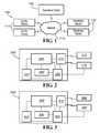
- FIG. 1is a schematic of one embodiment of the disclosed system.
- FIG. 2is a schematic of one embodiment of a monitoring device.
- FIG. 3is a schematic of one embodiment of a control device.
- FIG. 4Ais an exploded view of one embodiment of a device of the disclosure as housed within a fire hydrant.
- FIG. 4Bis a perspective view of a device of the disclosure attached to a fire hydrant
- FIG. 5Ais a perspective view of one embodiment of an insulation device for sealing the bonnet of the fire hydrant from the water within the fire hydrant.
- FIG. 5Bis a perspective view of one embodiment of an insulation device and bonnet.
- FIG. 6Ais a perspective view of one embodiment of a nozzle cap for attachment to a fire hydrant.
- FIG. 6Bis a sectional view of one embodiment of the nozzle cap of FIG. 6A .
- FIG. 6Cis a sectional view of one embodiment of the nozzle cap of FIG. 6A .
- the disclosures hereinprovide exemplary embodiments of the disclosed systems, methods, and devices. Features may be embodied in various and alternative forms. Therefore, there is no intent that specific structural and functional details should be limiting, but rather the intention is that they provide a basis for the claims and as a representative basis for teaching one skilled in the art to variously employ the present disclosure.
- a problem in the art capable of being solved by the embodiments disclosedis monitoring and maintaining an infrastructure. It has been discovered that monitoring devices with one or two way communication abilities can be used to detect faults in the municipality's systems and provide on-demand, real time, or near real time device status, maintenance, and control over the systems.
- a network of monitoring devicesis capable of providing a system administrator with a full picture of the current state of the system.
- the networkincludes an array of different monitoring devices each capable of sensing at least one condition.
- the monitoring devicesmay be capable of sending data to and of receiving data from at least one operations center.
- Communication from the remote monitoring devicemay be directed to a central monitoring facility, to one of a number of regional monitoring centers, to a user, and/or to a research facility.
- the systemincludes at least one control device. Each control device is adapted to control a different aspect of the system.
- the control devicesmay be part of the monitoring devices or may be separate units. Communication is over the Internet, but may be over a private network, a local area network, or a wide area network.
- the communicationinvolves a wireless component, such as from the remote monitoring device and/or control device to a regional monitoring facility or to distributed monitors. Also, the communications are secured or encrypted such that the communications system cannot be monitored by another unknown party. Access to the system is granted through user names and passwords, although additional and/or alternate encryption methods can be employed.
- monitoring devicescan be located throughout the system, for example, as attachments to component parts, for feedback to a network that can provide real-time information to the utility operating the network.
- the network operatorscan use the information transmitted to activate controlling devices on the network, or to dispatch repair or other services as directed by the information provided by the network. For example, if water pressure monitors on a water meter indicate a variance between locations, a water leak can be reported using the network, and controlling devices can divert water.
- Pressure meterscan be attached to fire hydrants to monitor and report pressure losses throughout the system, providing real-time information to benefit the users of the fire hydrants (fire departments who need to be assured of adequate pressure), the users of the system (water consumers who will be affected by lower pressure), and the operators of the system (who suffer asset loss as a result of lack of real-time information about losses).
- FIG. 1depicts a system 100 for monitoring, controlling, and communicating with at least one monitoring device 110 and/or at least one control device 111 .
- System 100includes an operations center 105 in communication with at least one monitoring device 110 and/or one control device 111 .
- operations center 105 and devices 110 and 111there is bi-directional communication between operations center 105 and devices 110 and 111 .
- Communicationscan be simplex or duplex. Communication can occur over any communications network 115 known in the art, including but not limited to wired networks, wireless networks, Zigbee networks, Bluetooth networks, Z-wave networks, WiFi networks, WiMax networks, RF networks, local area networks (LAN), internet networks, wide area networks (WAN), cellular telephone network, hardwired telephone networks, 900 MHz wireless networks, and satellite networks.
- the networkis a fixed network.
- the fixed networkcan be a mesh network or a star network.
- devices 110 and 111 and operations center 105can be in direct communication or can communicate through an intermediary device, such as a relay, a repeater, a gateway, or other device capable of receiving and retransmitting a message.
- Each monitoring device 110monitors at least one aspect of the infrastructure.
- the monitored aspectcan be one or more of the components of the infrastructure (e.g. pipe conditions, valve conditions, fire hydrant conditions, service line conditions, meter conditions, power line conditions, and battery conditions), commodity conditions (e.g. fluid or gas flow, fluid or gas pressure, fluid or gas temperature, and fluid or gas contaminants), or combinations thereof.
- each monitoring device 110can be self monitoring. For example the monitoring devices 110 determine if there is a loss of communication, low battery levels, and/or internal damage (e.g. short circuits due to water damage).
- each monitoring device 110can be structurally stable (e.g.
- valve boxfixed to a valve, pipe, utility pole, a hydrant, a valve box, a valve box cover, a meter, a meter box, a meter box cover, a water tower, a water tank, a pumper nozzle, a hose nozzle, or an manhole cover
- movablee.g. allowed to move with or within the flow of water or gas in the pipes.
- a monitoring device 110 or 111can be coupled to a fire hydrant 405 , a seen in FIG. 4B .
- the monitoring device 110 or 111can be located within a nozzle cap 600 (i.e. in the pumper nozzle, the hose nozzle, or in the fire truck hook up), within a body of the fire hydrant, within a bonnet, attached to an outside of the fire hydrant, or at another location on or within the fire hydrant.
- a housing for the monitoring device 110 or 111is made of plastic, nylon, other synthetic or natural materials, or any other material that does not block transmissions to and from the monitoring device 110 or 111 . For example, as shown in FIG.
- the fire hydrant bonnet 400can contain a monitoring device 110 and a waterproof container 420 for the monitoring device 110 .
- the fire hydrant bonnet 400can also contain a power source 425 .
- the monitoring device 110can be coupled to the outside of a fire hydrant 405 .
- the bonnet 500 of a fire hydrant 505can be isolated from the flow of water within the fire hydrant 505 .
- a monitoring device 110 or control device 111is positioned within a nozzle cap 600 of a fire hydrant.
- a fire hydrant nozzle cap 600is a device attached to an outlet nozzle and covers a nozzle opening.
- the nozzle cap 600is furnished with a nut 605 or other device to permit the application of force to firmly attach the nozzle cap 600 to or to remove it from the outlet nozzle.
- FIG. 6Adepicts an isometric view of an embodiment of the nozzle cap 600 .
- nozzle cap 600is made of a composite, plastic, nylon, other synthetic or natural materials, or any other material that does not block transmissions to and from the monitoring device 110 or control device 111 .
- the materialhas the same fading characteristics of the paint used on the exterior of the fire hydrant.
- the materialcan have the same resistance to water, UV rays, corrosion, oxidation, or other causes of fading. Thereby, the paint and the nozzle cap 600 appear to be of the same material.
- FIGS. 6B and 6Cdepict cutaway views of an embodiment of the nozzle cap 600 .
- the nozzle cap 600has an enclosure 610 which creates a cavity into which monitoring device 110 or control device 111 may be located. The cavity is enclosed by a cover 615 .
- the enclosure 610 and cover 615create a water tight seal able to withstand water pressures in excess of 400 psi. In various embodiments, other pressures may be utilized.
- nozzle cap 600has an antenna cover 620 .
- Antenna cover 620can be made of the same material as nozzle cap 600 or of a different material. The location of the antenna is kept away from metal to achieve greater efficiency.
- Nozzle hydrant threading 625is provided as a connection means between the nozzle cap 600 and the fire hydrant.
- the nozzle cap 600also includes enclosure threading 630 as a connection means for the enclosure 610 to connect to the nozzle cap 600 .
- the enclosure 610also includes connection threading 640 designed to mate with the enclosure threading 630 .
- An antenna 650is shown.
- Each node in the network 115detects errors in transmissions. Error detection can use cyclic redundancy codes using a table based on a defined polynomial or another method of error detection. In alternative embodiments, transmissions can be rerouted if the primary route is blocked or otherwise unavailable. Furthermore, devices 110 and 111 can confirm receipt of a message, e.g. via a hand shake protocol. In instances where confirmation is not received, the message can be resent along the same route or rerouted.
- each monitoring device 110 and each control device 111is assigned a unique identifier.
- the unique identifiercan be related to the devices' geographical locations, street addresses, order of installation, or any other method of identifying the devices 110 , 111 .
- different types of devices 110 and 111can have unique identifiers that include keys that are unique to that type of device. For example, the identifier for all water meters may begin with a WM, while the identifier for all leak detectors may begin with an LD.
- Each communication to and from a monitoring device 110 and control device 111may include the unique identifier so that the message is received by the correct monitoring device 110 or control device 111 , or so that operations center 105 can determine from where the message was sent.
- Each monitoring device 110 and each control device 111can be retrofitted to an existing system 100 or device 110 , 111 , can be coupled to a new system 100 or device 110 , 111 , or can be integrated into a new system 100 or device 110 , 111 .
- the system 100can be connected to, work with, or work independently of a Supervisory Control and Data Acquisition (SCADA) network.
- SCADASupervisory Control and Data Acquisition
- each monitoring device 110 and each control device 111has a set of adapters to facilitate coupling the monitoring device 110 or control device 111 to a new or existing system 100 or device 110 , 111 .
- system 100is divided into sectors with each sector having at least one monitoring device 110 and/or at least one control device 111 .
- Each sectorcan communicate directly with operations center 105 or each sector can have at least one intermediary communications device that is in communication with the monitoring device 110 and/or control device 111 and operations center 105 .
- the sectorsare divided up by geographical location. For example, all of the devices in one neighborhood can be in a single sector and there is one sector for each neighborhood.
- one intermediary communications devicecan service multiple sectors.
- each monitoring device 110 and/or control device 111can communicate with adjacent monitoring devices 110 and/or control devices 111 .
- each monitoring device 110 and/or control device 111can act as a transceiver or relay by receiving messages intended for another device 110 , 111 or for the operations center 105 and forwarding the message.
- monitoring devices 110 and control devices 111can communicate only within their sector.
- monitoring device 110 and control device 111can communicate with devices 110 , 111 in other sectors.
- Each monitoring device 110 , control device 111 , and/or the operations center 105may be able to determine if a transmitted message was received by the intended device 110 , 111 and, if not, may be able to reroute the message until the message is properly received.
- relay devicescan be implemented in the system to further extend the range of communications. For example, relay devices can be placed on utility poles, on municipal buildings, within fire hydrants, and/or under manhole covers.
- devices 110 and 111communicate over a mesh network. In the mesh network, devices 110 and 111 can communicate with other devices 110 and 111 within the mesh network.
- Operations center 105can set specified communications pathways derived from routing tables.
- Operations center 105can be located at a municipality office, a private or public company, a fire station, a police station, or any other entity that monitors operations center 105 .
- operations center 105can be remotely hosted and accessible by the Internet.
- operations center 105can take advantage of cloud computing (e.g. a network of remotely hosted computers, servers, and data storage devices). Compared to non-remotely hosted computer networks, cloud computing can increase ease of use, increase access, increase security, decrease costs, be custom tailored, and provide an unrestricted expansion of storage space. Additionally, in various embodiments, there is a plurality of operations centers 105 .
- One or more operations centers 105can be located at different entities and each operations center 105 can monitor a different aspect of system 100 .
- the water usage aspectcan be monitored by a water utility company and the gas leaks can be monitored by the gas utility company and/or the fire department.
- there are redundant operations centers 105where at least two operations centers 105 monitor the same aspect of system 100 .
- Operations center 105can send transmissions to update the firmware of devices 110 and 111 .
- FIG. 2is a schematic of a monitoring device unit 200 .
- Monitoring device unit 200includes a processor 205 .
- Processor 205is coupled to at least one input port 210 for receiving data from sensors 215 .
- Processor 205is also coupled to a transceiver 220 for sending and receiving signals.
- Processor 205is coupled to a data storage unit 230 .
- Data storage unit 230can hold a predetermined amount of data received from the sensors 215 .
- data storage unit 230can hold data for a predetermined amount of time (e.g. one day, one week, or one month), can hold a predetermined number of readings (e.g. 10 readings, 100 readings, 1000 readings), or can hold data until directed to purge the data by the operations center 105 .
- data storage unit 230can hold instructions for processor 205 to execute upon prompting from the operations center 105 .
- Processor 205compiles at least some of the data stored in data storage unit 230 for transmitting to the
- Each monitoring device unit 200may collect data and/or transmit data continuously, at specific intervals, or randomly. In embodiments where the monitoring device unit 200 collects and transmits data in a non-continuous configuration, monitoring device unit 200 may turn off or reduce power consumption during the non-data collecting periods to save energy.
- Processor 205is coupled to a power source 235 .
- Power source 235can be a unit capable of powering processor 205 and devices attached to processor 205 .
- power source 235can be a battery, solar panel array, wind turbine, water turbine, electrical lines, or combinations thereof.
- there is also a backup power sourcesuch as a battery. The power may derive from the operation of the system 100 .
- processor 205is coupled to at least one sensor 215 that monitors at least one condition associated with the monitoring device.
- Sensors 215can determine the status of a device.
- Sensors 215can be directly wired to processor 205 or can use wireless communication to send and receive signals from processor 205 .
- Sensors 215can be positioned within the monitoring device or be external to the monitoring device. In alternative embodiments, sensors 215 are positioned remote from the monitoring device. For example a sensor can be positioned in a fire hydrant, on a nearby building, or on a utility pole.
- the same communications protocolcan be used in the sensor/processor communication as in the processor/operations center communication, or different communications protocols can be used in the sensor/processor communication from in the processor/control center communication.
- the sensor/processor communicationscan use RF protocols while the processor/control center communications can be over a wired network.
- sensor 215is a use monitor.
- the use monitorrecords the amount of water, gas, electricity, or other commodity that is used by a customer over a specified period of time.
- the use monitorcan continuously record the amount of the commodity used or the use monitor can provide a signal to processor 205 that the commodity is in use.
- Processor 205can transmit a signal to the operations control to alert the operations center 105 that the monitoring device 110 is being used and/or how much of the commodity is flowing through the sensor 215 .
- the operations center 105can request a reading from the use monitor on demand.
- the processor 205 or the operations center 105can determine based on the use, if there is unauthorized use of the commodity.
- At least one of processor 205 or the operations center 105can generate an alarm that there is unauthorized use. For example, in embodiments where the use monitor is coupled to a fire hydrant 405 , if the use monitor indicates that the fire hydrant 405 is in use, however no fire is reported, the operations center 105 can disseminate an alert that there is potential misuse of the fire hydrant 405 .
- At least one sensor 215is a tamper sensor.
- the tamper sensorcan be a motion detector, a contact sensor, a rotation sensor, a touch sensor, a proximity sensor, a biofeedback sensor, a temperature sensor, a capacitance sensor, a resistance sensor, or any other sensor that is able to detect the presence of an object.
- the tamper sensorcan send a message to processor 205 when the tamper sensor detects an event.
- the processor 205will then evaluate the event to determine if a device being monitored is being tampered with or will relay the message to the operations center 105 for evaluation.
- the monitored devicecan be a fire hydrant, utility meter, valve, manhole cover, pump, or any other device that may be tampered with.
- processor 205 and the operations center 105can generate an alarm that the device is being tampered with.
- the monitoring devicemay activate a tamper prevention device (described below).
- the operations center 105will send a transmission to processor 205 telling processor 205 to disregard messages from the tamper sensor for a predetermined period of time or until another message is received from the operations center 105 telling processor 205 to resume monitoring for tamper events.
- the operations center 105will send a message to processor 205 to temporarily disregard any tamper events. Once the fire department is finished using the fire hydrant the operations center 105 will send a message to processor 205 to start monitoring for tamper events again.
- At least two of sensors 215are leak detectors.
- Each leak detectorcan include an in-pipe leak detector and/or an exterior leak detector.
- the leak detectorsare vapor sensors.
- the leak detectorsuse acoustic monitoring to determine presence and location of a leak. The energy generated from a leak is transmitted within a pipe through the commodity as well as through the pipe wall.
- Each leak detectorcan detect the vibrations made by the leak in the commodity or the pipe wall, joint or service line. To determine the location of a leak, at least two detectors must detect the same leak.
- the typical velocity of sound in wateris about 1500 m/s while the typical speed of sound through an iron pipe is 5100 m/s.
- the velocitycan be measured empirically. For example, if the leak is exactly midway between the two detectors the sound would reach both detectors at the same time. Each detector may monitor continuously or at predetermined periods of time.
- the leak detectorscan send a message to processor 205 when the leak detectors detect an event.
- the processor 205can then evaluate the event to determine if there is a leak and how severe the leak is or can relay the message to the operations center 105 for evaluation.
- at least one of processor 205 or the operations center 105can generate an alert that there is a leak if the leak is determined to be severe enough to warrant attention.
- At least one sensor 215is a smoke detector.
- the smoke detectorcan be a photoelectric detector, an ionization detector, or any other device that can detect the presence of smoke.
- the smoke detectorcan be located within the monitoring device or exterior to the monitoring device.
- the smoke detectormonitors continuously for smoke.
- the smoke detectorcan send a message to processor 205 when the smoke detector detects an event.
- the processor 205can then evaluate the event to determine if there is smoke or can relay the message to the operations center 105 for evaluation.
- at least one of processor 205 or the operations center 105can generate an alert that there is smoke.
- At least one sensor 215is a temperature sensor.
- the temperature sensorcan be a contact sensor (e.g. thermocouples, thermistors, liquid-in-glass thermometers, resistance temperature detectors, filled system thermometers, bimetallic thermometers, semiconductor temperature sensors, and phase change indicators) or a non-contact sensor (e.g. radiation thermometers, thermal imagers, ratio thermometers, optical pyrometers, and fiber optic thermometers).
- the temperature sensorcan be located within the monitoring device or exterior to the monitoring device. In one embodiment, the temperature sensor monitors continuously for the temperature to rise above or drop below a predetermined threshold. The temperature sensor can send a message to processor 205 when the temperature sensor detects a temperature beyond the thresholds.
- the processor 205can then evaluate the event to determine if there the temperature is a problem (such as freezing pipes or fire) or can relay the message to the operations center 105 for evaluation. Upon detection of undesirable temperatures, at least one of processor 205 or the operations center 105 can generate an alert that there is an undesirable temperature condition.
- a problemsuch as freezing pipes or fire
- At least one sensor 215is a rust and/or corrosion sensor.
- the corrosion sensorcan detect rust and/or corrosion using any method known in the art, including but not limited to liquid penetration inspection, magnetic particle inspection, radiographic inspection, visual inspection, eddy current inspection, ultrasonic inspection, and thermographic inspection.
- the corrosion sensorcan send a message to processor 205 when the corrosion sensor detects a rust or corrosion beyond a threshold value.
- the processor 205can then evaluate the rust or corrosion to determine if there is a problem or can relay the message to the operations center 105 for evaluation.
- at least one of processor 205 or the operations center 105can generate an alert that there is an undesirable amount of rust or corrosion.
- At least one sensor 215is a fluid flow sensor.
- the fluid flow sensorcan be used either in gas systems or liquid systems.
- the fluid flow sensorcan detect direction of the flow, turbidity of the flow, velocity of the flow, density of the flow, viscosity of the flow, and/or any other aspect of the flow.
- the fluid flow sensormay be a velocimeter, a laser-based interferometer, a vane, a rotary potentiometer, a Hall effect sensor, a device to measure heat transfer caused by the flowing fluid, or any other device know in the art to measure the flow of fluid.
- the fluid flow sensorcan send a message to processor 205 when the fluid flow sensor detects a flow anomaly.
- the processor 205can then evaluate the event to determine if the anomaly is a problem or can relay the message to the operations center 105 for evaluation. Upon detection of an anomaly, at least one of processor 205 and the operations center 105 can generate an alert that there is an anomaly.
- At least one sensor 215is a pressure sensor.
- the pressure sensoris positioned within the flow of fluid or area in which the pressure is being sensed.
- the pressure sensorcan be positioned at the base of a fire hydrant and in the water to determine the water pressure within water system, in a pipe to determine gas or water pressure within a gas or water system, or in a room to determine air pressure within the room.
- the pressure sensorcan be a piezoresistive strain gauge, a capacitive gauge, an electromagnetic gauge, a piezoelectric device, or any other device know in the art to measure pressure.
- the pressure sensorcan send a message to processor 205 when the pressure sensor detects a pressure anomaly.
- the processor 205can then evaluate the event to determine if the anomaly is a problem or can relay the message to the operations center 105 for evaluation. Upon detection of an anomaly, at least one of processor 205 or the operations center 105 can generate an alert that there is an anomaly.
- At least one sensor 215is a water quality monitor.
- the water quality monitorcan monitor a single aspect of water flowing through the system 100 or multiple aspects of the water.
- the water quality monitorcan monitor one or more of the water's bacteria levels, pharmaceutical levels, alkalinity, chlorine and/or chloramine levels, hardness, pH levels, peroxide content, iron levels, nitrate levels, nitrite levels, arsenic levels, pollution levels, oxygen levels, biomass levels, and/or any of the other contaminants regulated by the Environmental Protection Agency (EPA).
- EPAEnvironmental Protection Agency
- all the devicescan monitor the same aspects, each device can monitor a different aspect, or a combination thereof.
- the water quality monitorstest the water continuously, however, in alternative embodiments, the water quality monitors test the water at predetermined time intervals (e.g. once a hour, once a day, once a week, etc.). Each water quality monitor relays data to processor 205 .
- Processor 205can store the data on data storage unit 230 or transmit the data to the operations center 105 . Either processor 205 or the operations center 105 can monitor the data received from the water quality monitors to determine if there is a change in the levels of the contaminants or if the levels of the contaminants rise above a threshold level. Upon detection of unsafe contamination levels, at least one of processor 205 or the operations center 105 can generate an alert that there is contamination in the water system.
- the operations center 105can determine if there is a change in the aspect of the water from the location of one monitoring device to the location of the other. If there is a change, the operations center 105 can generate an alert that there is a change in the water system and output the approximate location of the change in the water system.
- At least one sensor 215is an air quality monitor.
- the air quality monitorcan monitor a single aspect of the air or multiple aspects of the air.
- the air quality monitorcan monitor the air within a facility or ambient air.
- the air quality monitorcan monitor one or more of the air's benzene levels, carbon disulfide levels, urethane levels, formaldehyde levels, phosphorus levels, naphthalene levels, parathion levels, quinoline levels, trifluralin levels, and/or any of the other contaminants whose acceptable levels have been set by the Environmental Protection Agency.
- all the devicescan monitor the same aspects or each device can monitor a different aspect, or a combination thereof.
- the air quality monitorstest the air continuously, however, in preferred embodiments, the air quality monitors test the air at predetermined time intervals (e.g. once a hour, once a day, once a week, etc.). Each air quality monitor relays data to processor 205 .
- Processor 205can store the data on data storage unit 230 or transmit the data to the operations center 105 .
- Either processor 205 or the operations center 105can monitor the data received from the air quality monitors to determine if there is a change in the levels of the contaminants or if the levels of the contaminants rise above a threshold level. Upon detection of unsafe contamination levels, at least one of processor 205 or the operations center 105 can generate an alert that there is contamination in the air.
- the operations center 105can determine if there is a change in the aspect of the air from the location of one monitoring device to the location of the other. If there is a change, the operations center 105 can generate an alert that there is a change in the air and output the approximate location of the change in the aspect of the air. Furthermore, in embodiments where there is a time stamp associated with each reading, the operations center 105 can determine the approximate direction and speed at which the contaminant is moving.
- At least one sensor 215is a radiation detector.
- the radiation detectorcan distinguish between natural sources of radiation and artificial sources of radiation or can distinguish between normal levels of radiation and abnormal levels of radiation.
- the radiation detectordetects ionizing radiation.
- Ionizing radiationconsists of subatomic particles or electromagnetic waves that are energetic enough to detach electrons from atoms or molecules, ionizing them. Examples of ionizing particles are energetic alpha particles, beta particles, and neutrons.
- the ability of an electromagnetic wave (photons) to ionize an atom or moleculedepends on its frequency. Radiation on the short-wavelength end of the electromagnetic spectrum—high frequency ultraviolet, x-rays, and gamma rays—is ionizing.
- the radiation detectoris one of a dosimeter, a Geiger counters, or a scintillation counters.
- Dosimetersmeasure an absolute dose received over a period of time. Ion-chamber dosimeters resemble pens, and can be clipped to one's clothing. Film-badge dosimeters enclose a piece of photographic film, which will become exposed as radiation passes through it. Ion-chamber dosimeters must be periodically recharged, and the result logged. Film-badge dosimeters must be developed as photographic emulsion so the exposures can be counted and logged; once developed, they are discarded. Another type of dosimeter is the TLD (Thermoluminescent Dosimeter).
- TLDscontain crystals that emit visible light when heated, in direct proportion to their total radiation exposure.
- TLDscan be re-used after they have been ‘read’.
- Geiger counters and scintillation countersmeasure the dose rate of ionizing radiation directly.
- the radiation detectoris a solid-state device.
- the radiation detectorcan relay the detection to processor 205 .
- Processor 205can save the detection on data storage unit 230 or transmit a message regarding the detection to the operations center 105 .
- Processor 205 or the operations center 105can evaluate the detection and act in accordance with the purpose of the radiation detector. For example, if the radiation detector detects radiation over a threshold level, processor 205 or the operations center 105 can generate an alert that there are unsafe radiation levels.
- At least one sensor 215is a motion detector.
- the motion detectorcan be a radar-based motion detector, a photo-sensor motion detector, a passive infrared motion detector, a magnetic motion detector, a pressure sensitive motion detector, or any other device capable of detecting the motion of objects.
- the motion detectorcan be used, for example, to count the number of cars passing through an intersection to control a traffic light, for tamper prevention as described above, for security purposes, and/or to control street lights.
- the motion detectorcan be placed within the monitoring device or exterior to the monitoring device.
- the motion detectorcan relay the detection to processor 205 .
- Processor 205can save the detection on data storage unit 230 or transmit a message regarding the detection to the operations center 105 .
- Processor 205 or the operations center 105can evaluate the detection and act in accordance with the purpose of the motion detector. For example, if the motion detector detects a predetermined number of vehicles have passed the monitoring device, processor 205 or the operations center 105 can cause a traffic light to switch from green to red. As a second example, if the motion detector detects a motion after a predetermined time, e.g. after sunset, processor 205 or the operations center 105 can cause the street lights near the monitoring device to illuminate for a predetermined period of time.
- a predetermined timee.g. after sunset
- At least one sensor 215is a tiltmeter.
- the tiltmetercan be a pendulum, a water tube, a bubble-level meter, and/or a MEMS electronic meter.
- the tiltmetercan be located on devices within the system, such as, but not limited to, pipes, fire hydrants, meters, valves, utility poles, manhole covers, and light posts.
- the tiltmetercan send a message to processor 205 when the sensor detects a tilt beyond a threshold value.
- the processor 205can then evaluate the tilt to determine if there is a problem or can relay the message to the operations center 105 for evaluation.
- at least one of processor 205 or the operations center 105can generate an alert that there is an undesirable tilt. For example, if a utility pole is struck by a car, the tiltmeter will indicate that the utility pole is tilting at an undesirable level and the operations center 105 can alert the municipality to send out a repair crew to assess the situation and repair the utility pole.
- At least one sensor 215is a proximity sensor.
- the proximity sensorcan use electromagnetic technology, electrostatic technology, infrared technology, or a touch switch.
- the proximity sensorcan detect if devices are properly closed or if devices are improperly touching.
- the proximity sensorcan send a message to processor 205 when the proximity sensor detects proximity beyond a threshold value.
- the processor 205can then evaluate the proximity to determine if there is a problem or can relay the message to the operations center 105 for evaluation.
- at least one of processor 205 or the operations center 105can generate an alert that there is an undesirable proximity. For example, if a valve is improperly closed, the proximity sensor will indicate that the valve is not closed and processor 205 can alert the municipality to take proper actions to close the valve.
- At least one sensor 215is a visual or audio device.
- the devicecan be an infrared camera, a video camera, a still camera, a digital camera, a film camera, a mobile vision device, a microphone, a vibration detector, combinations thereof, or any other device capable of acquiring an image or sound.
- the deviceis a digital video camera that takes video images continuously.
- the deviceis a digital still camera that takes still images at regular intervals or upon command from processor 205 .
- the devicecan be a traffic camera and take a picture when instructed to by processor 205 , for example upon determination that a vehicle is running a red light.
- the deviceis used to perform visual inspections of the system infrastructure.
- the field of view of the devicecan include a device within the system that is apt to corrode and the camera can provide an easy method to visually inspect any degradation of the device.
- the devicecan send image data to processor 205 where the data is stored on data storage unit 230 or is transmitted to the operations center 105 .
- image or sound datais streamed continuously from the device to processor 205 and from processor 205 to the operations center 105 .
- the data streamcan either be live or delayed.
- the devicecan be located on the monitoring device, near the monitoring device, or within the monitoring device with a portion of the device extending outside the monitoring device or with a hole in the monitoring device through which the device can obtain images or sounds.
- the deviceis positioned on an actuator.
- the actuatorcan move to reposition the field of view of the device.
- the actuatorcan move upon demand from processor 205 or can move autonomously. In the embodiments where the actuator moves autonomously, the movement can be continuous or sporadic.
- At least one sensor 215is a Global Positioning System (GPS) receiver.
- GPSGlobal Positioning System
- the GPS receiveris located on devices within the system 100 , such as, but not limited to, pipes, fire hydrants, meters, valves, utility poles, manhole covers, and light posts.
- the GPS receivercan send a message to processor 205 indicating GPS location.
- the processor 205can then relay the message to the operations center 105 for evaluation, conformation, and documenting.
- at least one of processor 205 or the operations center 105can generate an alert that the GPS receiver has moved, possibly indicating that the device has been dislodged, tampered with, or stolen.
- the GPS locationcan be used, for example, by emergency responders to locate fire hydrants, or repair crews to determine the location of a buried device.
- the operations center 105can disseminate information to the emergency responders or repair crews to easily locate the device.
- the disseminationcan occur by any method, including but not limited to, verbally, over a telecommunications network (e.g. to a smart phone or portable computer), or over a shortwave radio.
- the sensorcan provide updated locations of the monitoring device to track, for example, the flow or contamination levels within the flow.
- sensors 215 connected to monitoring device unit 200can include, but are not limited to, flow rate meters, backflow meters, system status monitors, and power level monitors.
- FIG. 3is a schematic of a control device 300 .
- Control device 300includes a processor 305 .
- Processor 305is coupled to at least one output port 310 for controlling an output device 340 .
- Processor 305is also coupled to a transceiver 320 for sending and receiving signals.
- Processor 305is communicatively coupled to output port 310 .
- Output port 310is connected to at least one output device 340 .
- Each output device 340can have the same purpose or each output device 340 can have a different purpose, or combinations thereof.
- Output devices 340can be located within control device 300 or external to control device 300 , as shown. Furthermore, output devices 340 can be attached to control device 300 or can be remote from control device 300 .
- Output devices 340communicate with output port 310 through wired or wireless communication channels.
- output devices 340are capable of bidirectional communication.
- control device 300is an integral part of a monitoring device. In such embodiments, the control device 300 and the monitoring device can share the same processor and/or transceiver.
- processor 305is coupled to a data storage unit 330 that may be a database in some embodiments.
- Data storage unit 330may store instructions for processor 305 of how to control output devices 340 .
- processor 305is coupled to a power source 335 .
- Power source 335can be any device capable of powering processor 305 and any devices attached to processor 305 .
- power source 335can be a battery, solar panel array, wind turbine, water turbine, electrical lines, or combinations thereof.
- there is also a backup power sourcesuch as a battery.
- At least one output device 340is an actuator control device.
- the actuator control devicecan control any type of actuator, including but not limited to, a tamper prevention device, a locking device, a camera motion device, a fire hydrant nut opening device, or a valve.
- the actuator control devicecan control the actuator autonomously or upon demand from processor 305 . For example, upon receiving a signal that a particular event has been sensed, processor 305 may send a command to the actuator control device to act in a particular manner. Likewise, in some embodiments the control signal may come from the operations center 105 .
- the actuatorcan be mechanical, electrical, or a combination thereof.
- At least one output device 340is an alarm.
- the alarmcan be a visual alarm, an audible alarm, a tactile (i.e. vibration) alarm, or a combination thereof.
- the alarmcan be located within the monitoring device, exterior to the monitoring device, at the operations center 105 , remote from the system, or any other location sufficient to alert. Furthermore, there can be more than one alarm at different locations.
- the alarmis controlled by the processor 305 , while in other embodiments the alarm is controlled by the operations center 105 . In various embodiments, the alarm has an on/off switch controllable locally.
- At least one output device 340is a tamper prevention device.
- the tamper prevention devicecan be a mechanical lock, an alarm, a light, an electrical shock generator, a retaining device, an electrical lock, or any other device capable of preventing tampering.
- the tamper prevention devicemay merely deter tampering or may incapacitate a person who is trying to tamper with the device, depending on the level of security.
- the tamper prevention deviceis controlled by the processor 305 , while in other embodiments the tamper prevention device is controlled by the operations center 105 .
- At least one output device 340is a Radio-Frequency Identification (RFID) device.
- RFIDRadio-Frequency Identification
- the RFID devicecan broadcast information about the device to which it is attached. For example, the RFID device may broadcast manufacturer information, location information, last service date, device information (e.g. make, model, and/or year), current status (e.g. a valve can broadcast if it is open or closed), etc.
- the RFID deviceis updateable by the processor 305 or by the operations center 105 .
- the RFID devicecan be either an active (e.g. battery powered) or passive (e.g. require an external source to provoke signal transmission) device.
- a system of the disclosureis monitoring a water distribution infrastructure.
- the systemis used to automatically control the water pressure within the system.
- Such a systemincludes a number of water meters disbursed throughout the infrastructure relaying real time use information to a control center.
- the operations centerUpon a determination by the operations center that there is low usage of the system (e.g. at night) based on information received by a predetermined number of the water meters, the operations center causes pumps supplying pressure within the system to reduce or cease pumping. Thereby cutting down on the electricity used by the pumps while maintaining enough pressure throughout the infrastructure to satisfy any water needs.
- the determination to reduce or cease pumpingcan be also based on information received from pressure sensors disbursed throughout the infrastructure. For example, if the pressure within the infrastructure exceeds a threshold value, the operations center causes the pumps to reduce or cease pumping.
- the systemis used to assist in maintaining the infrastructure. Water pipes and valves are often buried underground making it difficult to locate, assess the status of the devices, and repair them if necessary.
- each deviceis equipped with a monitoring the device.
- the monitoring devicemay monitor for corrosion using a corrosion monitor, geographical location using a GPS receiver, and leaks using a leak detector.
- the monitoring deviceUpon detection of corrosion and/or a leak, the monitoring device sends a message to the operations center where the information is analyzed.
- the operations centeris able to make a determination if the corrosion and/or leak is severe enough to warrant fixing, if the corrosion and/or leak should be watched to determine if it worsens, or if the corrosion and/or leak can be ignored.
- the operations centerwill also alert a person of the situation for further assessment.
- the operations centerdisseminates information to a repair crew and redirects water flow away from the device.
- informationcan include location of the device, based on data received the GPS receiver, problem associated with the device, device information (e.g. make, model, and/or year), etc.
- the monitoring devicecan also be equipped with a RFID transmitter, which transmits at least some of the above information.
- the repair crewreceives the information on a smart phone, a portable computer, or other device capable of receiving such information.
- the operations centerupdates the system to indicate a new last repaired date for the device.
- the systemis monitored by several entities within a municipality at the same time.
- a fire departmentUpon detection of smoke by a monitoring device, the control center alerts each entity of a potential fire.
- the location of the potential fireis determined by cross-referencing the ID number of the monitoring device with a lookup table or based on information received from a GPS receiver.
- the fire departmentuses the location information to send out emergency response personnel to the vicinity of the potential fire.
- the gas utilityuses the location information to divert or shut off gas flow to the vicinity of the potential fire.
- the water utilityuses the location information to divert water to or increase water pressure in the vicinity of the potential fire as well as determines if any fire hydrants in the vicinity of the potential fire are potentially damaged (e.g. are tilted at an unusual angle, are receiving no or little water pressure, or have been tampered with) based on information received from monitoring devices attached to the fire hydrants.
- the location of the fire hydrantsis determined by cross-referencing the ID number of the monitoring device with a lookup table or based on information received from a GPS receiver.
- the water utilityautomatically alerts the fire department as to which fire hydrants to use.
- the water utilityalso disables any tamper prevention devices associated with the fire hydrants.
- the electric utilityreceives a signal that additional pressure may be needed within the water system and provides an increased electrical load to the water pumps. Additionally, the traffic control center adjusts traffic lights en route from the fire station to the vicinity of the potential fire to assist the fire trucks in arriving quickly and safely.
- the systemis used to monitor contamination of the fluid flowing through the system.
- the systemincludes pressure sensors, leak detectors and contamination detectors. Leaks within the system can cause a pressure drop throughout the system which can lead to contaminants being drawn into the system. For example, if a pipe is under water and the pressure inside the pipe drops below the pressure outside the pipe, the exterior water will flow into the pipe. Therefore, the system has several monitoring devices to check for such potential or actual contamination.
- the pressure sensorswill indicate if the pressure within the system drops below a threshold level at which contaminants can be drawn into the system.
- the leak detectorswill indicate that there is a leak through which contaminants can enter the system. While the contamination detectors will indicate if there is contamination within the system, indicating a possible breach of the infrastructure of the system.
Landscapes
- Engineering & Computer Science (AREA)
- General Engineering & Computer Science (AREA)
- Mechanical Engineering (AREA)
- Health & Medical Sciences (AREA)
- Public Health (AREA)
- General Physics & Mathematics (AREA)
- Physics & Mathematics (AREA)
- Water Supply & Treatment (AREA)
- Life Sciences & Earth Sciences (AREA)
- Hydrology & Water Resources (AREA)
- Emergency Management (AREA)
- Business, Economics & Management (AREA)
- Fluid Mechanics (AREA)
- Computer Networks & Wireless Communication (AREA)
- Signal Processing (AREA)
- Alarm Systems (AREA)
- Arrangements For Transmission Of Measured Signals (AREA)
- Measurement Of Mechanical Vibrations Or Ultrasonic Waves (AREA)
- Radio Relay Systems (AREA)
Abstract
Description
L=(D−(V×T))/2
Claims (23)
Priority Applications (7)
| Application Number | Priority Date | Filing Date | Title |
|---|---|---|---|
| US13/101,235US8931505B2 (en) | 2010-06-16 | 2011-05-05 | Infrastructure monitoring devices, systems, and methods |
| US14/557,754US9861848B2 (en) | 2010-06-16 | 2014-12-02 | Infrastructure monitoring devices, systems, and methods |
| US14/848,676US9849322B2 (en) | 2010-06-16 | 2015-09-09 | Infrastructure monitoring devices, systems, and methods |
| US15/817,172US10881888B2 (en) | 2010-06-16 | 2017-11-18 | Infrastructure monitoring devices, systems, and methods |
| US16/675,507US10857403B2 (en) | 2010-06-16 | 2019-11-06 | Infrastructure monitoring devices, systems, and methods |
| US17/071,632US11590376B2 (en) | 2010-06-16 | 2020-10-15 | Infrastructure monitoring devices, systems, and methods |
| US18/070,154US20230108605A1 (en) | 2010-06-16 | 2022-11-28 | Infrastructure monitoring devices, systems, and methods |
Applications Claiming Priority (2)
| Application Number | Priority Date | Filing Date | Title |
|---|---|---|---|
| US35546810P | 2010-06-16 | 2010-06-16 | |
| US13/101,235US8931505B2 (en) | 2010-06-16 | 2011-05-05 | Infrastructure monitoring devices, systems, and methods |
Related Child Applications (1)
| Application Number | Title | Priority Date | Filing Date |
|---|---|---|---|
| US14/557,754ContinuationUS9861848B2 (en) | 2010-06-16 | 2014-12-02 | Infrastructure monitoring devices, systems, and methods |
Publications (2)
| Publication Number | Publication Date |
|---|---|
| US20110308638A1 US20110308638A1 (en) | 2011-12-22 |
| US8931505B2true US8931505B2 (en) | 2015-01-13 |
Family
ID=45327603
Family Applications (7)
| Application Number | Title | Priority Date | Filing Date |
|---|---|---|---|
| US13/101,235Active2032-07-14US8931505B2 (en) | 2010-06-16 | 2011-05-05 | Infrastructure monitoring devices, systems, and methods |
| US14/557,754ActiveUS9861848B2 (en) | 2010-06-16 | 2014-12-02 | Infrastructure monitoring devices, systems, and methods |
| US14/848,676ActiveUS9849322B2 (en) | 2010-06-16 | 2015-09-09 | Infrastructure monitoring devices, systems, and methods |
| US15/817,172Active2031-07-24US10881888B2 (en) | 2010-06-16 | 2017-11-18 | Infrastructure monitoring devices, systems, and methods |
| US16/675,507ActiveUS10857403B2 (en) | 2010-06-16 | 2019-11-06 | Infrastructure monitoring devices, systems, and methods |
| US17/071,632ActiveUS11590376B2 (en) | 2010-06-16 | 2020-10-15 | Infrastructure monitoring devices, systems, and methods |
| US18/070,154PendingUS20230108605A1 (en) | 2010-06-16 | 2022-11-28 | Infrastructure monitoring devices, systems, and methods |
Family Applications After (6)
| Application Number | Title | Priority Date | Filing Date |
|---|---|---|---|
| US14/557,754ActiveUS9861848B2 (en) | 2010-06-16 | 2014-12-02 | Infrastructure monitoring devices, systems, and methods |
| US14/848,676ActiveUS9849322B2 (en) | 2010-06-16 | 2015-09-09 | Infrastructure monitoring devices, systems, and methods |
| US15/817,172Active2031-07-24US10881888B2 (en) | 2010-06-16 | 2017-11-18 | Infrastructure monitoring devices, systems, and methods |
| US16/675,507ActiveUS10857403B2 (en) | 2010-06-16 | 2019-11-06 | Infrastructure monitoring devices, systems, and methods |
| US17/071,632ActiveUS11590376B2 (en) | 2010-06-16 | 2020-10-15 | Infrastructure monitoring devices, systems, and methods |
| US18/070,154PendingUS20230108605A1 (en) | 2010-06-16 | 2022-11-28 | Infrastructure monitoring devices, systems, and methods |
Country Status (7)
| Country | Link |
|---|---|
| US (7) | US8931505B2 (en) |
| EP (1) | EP2582886B1 (en) |
| JP (2) | JP5654124B2 (en) |
| AU (1) | AU2011265675B2 (en) |
| CA (5) | CA3177996A1 (en) |
| MX (3) | MX348843B (en) |
| WO (1) | WO2011159403A1 (en) |
Cited By (30)
| Publication number | Priority date | Publication date | Assignee | Title |
|---|---|---|---|---|
| US20150090049A1 (en)* | 2013-05-17 | 2015-04-02 | U.S. Environmental Protection Agency | Flow imaging and monitoring for synchronized management of wide area drainage |
| US20150161021A1 (en)* | 2013-12-09 | 2015-06-11 | Samsung Electronics Co., Ltd. | Terminal device, system, and method for processing sensor data stream |
| US9202362B2 (en) | 2008-10-27 | 2015-12-01 | Mueller International, Llc | Infrastructure monitoring system and method |
| US9494249B2 (en) | 2014-05-09 | 2016-11-15 | Mueller International, Llc | Mechanical stop for actuator and orifice |
| US9565620B2 (en) | 2014-09-02 | 2017-02-07 | Mueller International, Llc | Dynamic routing in a mesh network |
| US9593999B2 (en) | 2011-08-12 | 2017-03-14 | Mueller International, Llc | Enclosure for leak detector |
| RU2620023C1 (en)* | 2016-08-09 | 2017-05-22 | Общество с ограниченной ответственностью "ТЕХНОАС-СК" | Method of determining the place of the flow in the pipeline and the device for its implementation |
| US9799204B2 (en) | 2009-05-22 | 2017-10-24 | Mueller International, Llc | Infrastructure monitoring system and method and particularly as related to fire hydrants and water distribution |
| US9849322B2 (en) | 2010-06-16 | 2017-12-26 | Mueller International, Llc | Infrastructure monitoring devices, systems, and methods |
| US10039018B2 (en) | 2011-10-27 | 2018-07-31 | Mueller International, Llc | Systems and methods for recovering an out-of-service node in a hierarchical network |
| US10283857B2 (en) | 2016-02-12 | 2019-05-07 | Mueller International, Llc | Nozzle cap multi-band antenna assembly |
| US10305178B2 (en) | 2016-02-12 | 2019-05-28 | Mueller International, Llc | Nozzle cap multi-band antenna assembly |
| US10564014B2 (en)* | 2017-05-30 | 2020-02-18 | Nelson Manufacturing Company | Water consumption meter |
| US10859462B2 (en) | 2018-09-04 | 2020-12-08 | Mueller International, Llc | Hydrant cap leak detector with oriented sensor |
| US10921304B2 (en) | 2015-09-21 | 2021-02-16 | AMI Investments, LLC | Remote monitoring of water distribution system |
| US10934693B2 (en) | 2019-06-07 | 2021-03-02 | Mueller International, Llc | Hydrant monitoring system |
| US10941545B2 (en) | 2019-06-07 | 2021-03-09 | Mueller International, Llc | Hydrant monitoring system |
| US10968609B2 (en) | 2019-06-07 | 2021-04-06 | Mueller International, Llc | Self-contained hydrant monitoring system |
| US11041839B2 (en) | 2015-06-05 | 2021-06-22 | Mueller International, Llc | Distribution system monitoring |
| US11054404B2 (en)* | 2018-10-16 | 2021-07-06 | Novinium, Inc. | Methods of using dilution of a first type to calibrate one or more sensors |
| US11067464B2 (en)* | 2019-01-18 | 2021-07-20 | Mueller International, Llc | Wet barrel hydrant with pressure monitoring and leak detection |
| US11313748B2 (en) | 2019-01-18 | 2022-04-26 | Mueller International, Llc | Pressure monitor housing with cap-engaging projection |
| US20220127827A1 (en)* | 2020-03-03 | 2022-04-28 | Mueller International, Llc | Hydrant nozzle cap spacer |
| US11342656B2 (en) | 2018-12-28 | 2022-05-24 | Mueller International, Llc | Nozzle cap encapsulated antenna system |
| US11400328B2 (en) | 2019-06-07 | 2022-08-02 | Mueller International, Llc | Hydrant monitoring communications hub |
| US11473993B2 (en) | 2019-05-31 | 2022-10-18 | Mueller International, Llc | Hydrant nozzle cap |
| US11542690B2 (en) | 2020-05-14 | 2023-01-03 | Mueller International, Llc | Hydrant nozzle cap adapter |
| US11615682B2 (en) | 2019-06-27 | 2023-03-28 | Carrier Corporation | Smoke detection and localization based on cloud platform |
| US20230324244A1 (en)* | 2018-06-08 | 2023-10-12 | Orbis Intelligent Systems, Inc. | Detection device for a fluid conduit or fluid dispensing device |
| US11988656B2 (en) | 2015-09-21 | 2024-05-21 | Mcwane, Inc. | Remote monitoring of water distribution system |
Families Citing this family (114)
| Publication number | Priority date | Publication date | Assignee | Title |
|---|---|---|---|---|
| US7444401B1 (en) | 2002-11-18 | 2008-10-28 | Arkion Systems Llc | Method and apparatus for inexpensively monitoring and controlling remotely distributed appliances |
| US8335596B2 (en)* | 2010-07-16 | 2012-12-18 | Verizon Patent And Licensing Inc. | Remote energy management using persistent smart grid network context |
| US8833390B2 (en) | 2011-05-31 | 2014-09-16 | Mueller International, Llc | Valve meter assembly and method |
| US8788222B2 (en) | 2011-07-25 | 2014-07-22 | International Business Machines Corporation | Detection of pipeline contaminants |
| US8990033B2 (en) | 2011-07-27 | 2015-03-24 | International Business Machines Corporation | Monitoring operational conditions of a cargo ship through use of sensor grid on intermodal containers |
| US8706325B2 (en) | 2011-07-27 | 2014-04-22 | International Business Machines Corporation | Evaluating airport runway conditions in real time |
| KR101089644B1 (en)* | 2011-07-28 | 2011-12-07 | 주식회사 옥타컴 | Mobile system and method for measuring flow by channel |
| US8538667B2 (en) | 2011-07-28 | 2013-09-17 | International Business Machines Corporation | Evaluating road conditions using a mobile vehicle |
| US9207089B2 (en) | 2011-10-04 | 2015-12-08 | International Business Machines Corporation | Mobility route optimization |
| US9322657B2 (en) | 2011-10-04 | 2016-04-26 | International Business Machines Corporation | Mobility route optimization |
| US9146112B2 (en) | 2011-10-04 | 2015-09-29 | International Business Machines Corporation | Mobility route optimization |
| US8660134B2 (en) | 2011-10-27 | 2014-02-25 | Mueller International, Llc | Systems and methods for time-based hailing of radio frequency devices |
| US9413689B1 (en) | 2011-11-11 | 2016-08-09 | On Track Technologies Inc. | Mobile intelligent tracking and communication hub |
| US9287963B2 (en) | 2012-04-20 | 2016-03-15 | Mueller International, Llc | Relay modules for communication within a mesh network |
| WO2013177542A1 (en)* | 2012-05-25 | 2013-11-28 | Mueller International, Llc | Position indicator for valves |
| HRP20120603A2 (en)* | 2012-07-23 | 2014-01-31 | Igor IGNAC | Telemetry hydrant for measuring, collecting and wireless sending measured values into database on remote computer |
| DK2912416T3 (en) | 2012-10-26 | 2018-09-10 | Mueller Int Llc | Detecting Leaks in a Fluid Distribution System |
| US20140158920A1 (en)* | 2012-12-08 | 2014-06-12 | Masco Corporation | Digital proximity sensor |
| US9217999B2 (en)* | 2013-01-22 | 2015-12-22 | General Electric Company | Systems and methods for analyzing data in a non-destructive testing system |
| EP2948746A4 (en)* | 2013-01-28 | 2016-08-03 | Aquarius Spectrum Ltd | Method and apparatus for detecting leaks in a pipeline network |
| DE102013201299B4 (en)* | 2013-01-28 | 2016-09-29 | Matthias Deufert | Fitting for extinguishing water system |
| US8614745B1 (en) | 2013-02-04 | 2013-12-24 | Wasmeyyah M. A. S. Al Azemi | Fire hydrant monitoring system |
| WO2014151384A1 (en)* | 2013-03-15 | 2014-09-25 | Mueller International, Llc | Systems for measuring properties of water in a water distribution system |
| JP6066797B2 (en)* | 2013-03-28 | 2017-01-25 | 積水化学工業株式会社 | Status management support system and status management support method |
| JP5858439B2 (en)* | 2013-04-15 | 2016-02-10 | 山大機電株式会社 | Water intake equipment in rivers |
| WO2015152944A1 (en)* | 2014-04-04 | 2015-10-08 | Sicpa Security Inks & Systems Usa, Inc. | Interface to generate data compatible with an external system in an oil and gas asset supply chain |
| WO2015191324A2 (en)* | 2014-05-30 | 2015-12-17 | Reylabs Inc. | Systems and methods involving mobile indoor energy efficiency exploration, monitoring and/or display aspects |
| US9961418B2 (en)* | 2014-06-20 | 2018-05-01 | 3M Innovative Properties Company | Data communication appratus, system, and method |
| US10201847B2 (en) | 2014-07-09 | 2019-02-12 | The Boeing Company | Clamping feet for an end effector |
| US9528903B2 (en) | 2014-10-01 | 2016-12-27 | Mueller International, Llc | Piezoelectric vibration sensor for fluid leak detection |
| WO2016058802A1 (en) | 2014-10-14 | 2016-04-21 | Sicpa Holding Sa | Interface with secure intermediary platform to generate data compatible with an external system in an oil and gas asset supply chain |
| CN104361703A (en)* | 2014-11-17 | 2015-02-18 | 天津开发区瑞锋科技有限公司 | Well lid removing and damage warning device |
| GB201506775D0 (en)* | 2015-04-21 | 2015-06-03 | The Technology Partnership Plc | Gas pipe security device |
| US9661156B2 (en)* | 2015-05-21 | 2017-05-23 | Toshiba America Business Solutions, Inc. | Error assistance using heads-up display |
| US10754360B2 (en)* | 2015-06-01 | 2020-08-25 | Vidtek Associates Inc. | Wireless leak alarm, and wireless valve, apparatus, system and a method thereof |
| US11361650B2 (en)* | 2015-06-01 | 2022-06-14 | Vidtek Associates, Inc. | Wireless leak alarm camera and sensors, and wireless valve, apparatus, system and method thereof |
| ITUB20151837A1 (en)* | 2015-07-01 | 2017-01-01 | Patavina Tech S R L | SYSTEM FOR MONITORING AND CONTROL OF EXTINGUISHERS AND / OR HYDRANTS AND OF THE INTERACTION BETWEEN THEM |
| IN2015CH04425A (en)* | 2015-08-24 | 2015-09-04 | Wipro Ltd | |
| FR3043204B1 (en)* | 2015-11-02 | 2024-06-14 | Suez Environnement | METHOD FOR MEASURING CORROSION DEGRADATION OF A METALLIC PIPE AND MOBILE MEASURING DEVICE IMPLEMENTING SUCH A METHOD |
| DE102016201235A1 (en)* | 2016-01-28 | 2017-08-03 | Minimax Gmbh & Co. Kg | Mist system |
| CN105561514A (en)* | 2016-02-04 | 2016-05-11 | 浙江创丰智能电子科技有限公司 | Intelligent firefighting system |
| CN105561513A (en)* | 2016-02-04 | 2016-05-11 | 浙江创丰智能电子科技有限公司 | Smart fire-fighting management and control system |
| US10267774B2 (en)* | 2016-02-29 | 2019-04-23 | Mueller International, Llc | External noisemaker for pipe systems |
| US20170296851A1 (en)* | 2016-04-19 | 2017-10-19 | Protector Safety Ind., Ltd. | Fire Fighting Sprinkler Device Having Leveling Correcting Function |
| US20170316678A1 (en)* | 2016-04-28 | 2017-11-02 | Brian DeAngelo | Anti-jamming alarm security system |
| CN105862986A (en)* | 2016-06-08 | 2016-08-17 | 江苏赛达电子科技有限公司 | Antitheft fire hydrant |
| US10094100B2 (en)* | 2016-08-18 | 2018-10-09 | Stephen A Merlo | Water backup prevention system |
| AT519080B1 (en)* | 2016-09-09 | 2018-07-15 | Hawle Service Gmbh | Device for monitoring a hydrant |
| CN106669086B (en)* | 2016-11-25 | 2018-08-24 | 温州中盟智能科技有限公司 | A kind of intelligent fire bolt |
| WO2018125740A1 (en)* | 2016-12-28 | 2018-07-05 | Itron, Inc. | Measuring contamination to determine leak location |
| WO2018154571A1 (en)* | 2017-02-21 | 2018-08-30 | Hydrantech Ltd. | Method and system for identifying flow in hydrant outlet |
| US10846819B2 (en)* | 2017-04-12 | 2020-11-24 | Southern Methodist University | Method and apparatus to infer structural stresses with visual image and video data |
| CA3068298A1 (en)* | 2017-06-27 | 2019-01-03 | Nch Corporation | Automated plumbing system sensor warning system and method |
| DE102017117426A1 (en)* | 2017-08-01 | 2019-02-07 | Minimax Gmbh & Co. Kg | Sprinkler valve |
| US11709222B2 (en)* | 2017-08-14 | 2023-07-25 | Hadronex, Inc. | Manhole cover roadway electromagnetic safety device |
| FR3071166B1 (en)* | 2017-09-21 | 2020-11-13 | Le Savoir Ind | DEVICE FOR MONITORING AND COMMANDING THE OPERATION OF A FIRE TERMINAL AND ASSOCIATED INSTALLATION |
| CN107866022A (en)* | 2017-11-08 | 2018-04-03 | 麦克传感器股份有限公司西安分公司 | A kind of integral and intelligent fire hydrant |
| CN107929985A (en)* | 2017-11-21 | 2018-04-20 | 江西荣和特种消防设备制造有限公司 | Fire monitor |
| US20190176987A1 (en)* | 2017-12-13 | 2019-06-13 | James E. Beecham | System and method for fire suppression via artificial intelligence |
| KR101893898B1 (en)* | 2018-03-05 | 2018-09-03 | 주식회사 엔시드 | Smart hydrant |
| BE1026141B1 (en)* | 2018-03-29 | 2019-10-28 | Hydroko | Underground fire hydrant with a closing cap |
| DE102018109734A1 (en)* | 2018-04-23 | 2019-10-24 | Servatius Schneiders | Method and device for consumption measurement |
| KR102096978B1 (en)* | 2018-05-03 | 2020-04-03 | 주식회사 이레소방엔지니어링 | system for warning a driver of a parking violation |
| CN112334867A (en) | 2018-05-24 | 2021-02-05 | 纽约州立大学研究基金会 | Capacitive sensor |
| EP3803312A1 (en) | 2018-06-08 | 2021-04-14 | Orbis Intelligent Systems, Inc. | Pipe sensors |
| US11733115B2 (en) | 2018-06-08 | 2023-08-22 | Orbis Intelligent Systems, Inc. | Detection devices for determining one or more pipe conditions via at least one acoustic sensor and including connection features to connect with an insert |
| US11698314B2 (en) | 2018-06-08 | 2023-07-11 | Orbis Intelligent Systems, Inc. | Detection device for a fluid conduit or fluid dispensing device |
| JP7193832B2 (en)* | 2018-06-12 | 2022-12-21 | 下西技研工業株式会社 | Communication device |
| US11167161B1 (en)* | 2018-07-10 | 2021-11-09 | Senthuran Pon Suntharalingam | Hydrant monitoring system |
| CN109621273A (en)* | 2018-10-25 | 2019-04-16 | 安徽新浩信息科技有限公司 | A method for identifying abnormal pressure of fire hydrant based on artificial intelligence |
| US11016189B2 (en) | 2018-11-14 | 2021-05-25 | Honeywell International Inc. | Systems and methods for security system device tamper detection |
| WO2020112216A1 (en)* | 2018-11-30 | 2020-06-04 | Carrier Corporation | Fire suppression system remote monitoring |
| CN109794029A (en)* | 2018-12-11 | 2019-05-24 | 泉州市晋源消防水暖有限公司 | A kind of intelligent fire bolt |
| JP7440260B2 (en)* | 2018-12-20 | 2024-02-28 | 株式会社クボタ | Field water management system and hydrant control device |
| CN109621269B (en)* | 2018-12-21 | 2021-03-30 | 安耐特消防装备有限公司 | Intelligent indoor fire hydrant system |
| CN109995143A (en)* | 2019-04-24 | 2019-07-09 | 任金伟 | A kind of electric equipment safety device |
| CN111939510B (en)* | 2019-05-15 | 2021-10-01 | 北京泽惠风消防技术有限公司 | Fire hydrant pressure testing device and indoor fire hydrant system function detection method |
| DE102019119258A1 (en)* | 2019-07-16 | 2021-01-21 | VAG GmbH | Fitting |
| CN110237474B (en)* | 2019-07-31 | 2020-12-18 | 安徽中轩信息技术有限公司 | a fire hydrant |
| NL2023673B1 (en)* | 2019-08-20 | 2021-04-21 | Alliander N V | Energy distribution network |
| CN110433441B (en)* | 2019-08-20 | 2020-11-20 | 合肥科大立安安全技术有限责任公司 | Water pressure detection system for fire hydrant |
| CA3057655A1 (en)* | 2019-10-04 | 2021-04-04 | Wave9 Technology Inc. | Remote montoring method using image processing intelligence |
| CN111195408A (en)* | 2019-12-31 | 2020-05-26 | 浙江微天下信息科技股份有限公司 | Wisdom fire hydrant monitored control system |
| CN111174981A (en)* | 2020-01-19 | 2020-05-19 | 浙江天地人科技有限公司 | Outdoor fire hydrant water seepage detection method and system |
| WO2021170187A1 (en)* | 2020-02-24 | 2021-09-02 | Avk Holding A/S | An adapter cap for a fire hydrant, a fire hydrant and a method for remote monitoring an open-close status of a fire hydrant |
| CN111549957A (en)* | 2020-05-19 | 2020-08-18 | 郑峰 | Household or commercial kitchen ceiling type multifunctional intelligent water storage tank |
| CN111643846B (en)* | 2020-05-25 | 2021-09-14 | 劲源科技发展有限公司 | Fire hydrant intelligent monitoring device based on Internet of things |
| CN111827410A (en)* | 2020-06-30 | 2020-10-27 | 西安工程大学 | A fire hydrant system with positioning function |
| US11725366B2 (en) | 2020-07-16 | 2023-08-15 | Mueller International, Llc | Remote-operated flushing system |
| CN112121349A (en)* | 2020-09-22 | 2020-12-25 | 江西省智能产业技术创新研究院 | Outdoor fire hydrant internet of things monitoring system and method |
| CN112402884A (en)* | 2020-10-20 | 2021-02-26 | 嘉合智能科技股份有限公司 | Online monitoring system for running state of intelligent fire hydrant |
| US11601506B2 (en) | 2020-12-18 | 2023-03-07 | Itron, Inc. | Disaggregation of gas load to determine gas appliance performance |
| US11971285B2 (en) | 2020-12-18 | 2024-04-30 | Itron, Inc. | Detection of low gas pressure without pressure sensors |
| US11982373B2 (en) | 2020-12-18 | 2024-05-14 | Itron, Inc. | Gas regulator diaphragm-position and pressure-relief detection |
| US12196593B2 (en) | 2020-12-18 | 2025-01-14 | Itron, Inc. | Network edge detection and notification of gas pressure situation |
| US12080147B2 (en) | 2020-12-18 | 2024-09-03 | Itron, Inc. | Determining alternative outcome or event based on aggregated data |
| US12043992B2 (en) | 2020-12-18 | 2024-07-23 | Itron, Inc. | Determining backflow condition in water distribution system |
| US11594117B2 (en) | 2020-12-18 | 2023-02-28 | Itron, Inc. | Network edge detection and notification of gas pressure situation |
| US11971291B2 (en) | 2020-12-18 | 2024-04-30 | Itron, Inc. | Gas regulator pressure-relief monitor |
| US11733075B2 (en) | 2020-12-18 | 2023-08-22 | Itron, Inc. | Disaggregation of gas load to determine meter or service under-sizing |
| CN112402885A (en)* | 2020-12-21 | 2021-02-26 | 杭州智缤科技有限公司 | Installation and debugging method of intelligent fire hydrant |
| WO2022149137A1 (en)* | 2021-01-06 | 2022-07-14 | Amar Eli | Water flow anti-tampering and anti-theft device |
| CN112526505B (en)* | 2021-02-08 | 2021-05-07 | 天宇利水信息技术成都有限公司 | Circulating cableway radar wave flow measuring system |
| CN113262419B (en)* | 2021-05-28 | 2022-07-01 | 杭州传感器有限公司 | Fire hydrant valve plug, fire fighting system and monitoring method of fire hydrant valve plug |
| TWI783803B (en)* | 2021-12-01 | 2022-11-11 | 台灣電力股份有限公司 | Method for measuring steam pressure |
| WO2023131884A1 (en)* | 2022-01-05 | 2023-07-13 | Tyco Fire Products Lp | Systems and methods for indicating device state |
| WO2023235174A1 (en)* | 2022-06-02 | 2023-12-07 | Ademco Inc. | Pressure data for utility monitoring |
| WO2023239828A1 (en)* | 2022-06-10 | 2023-12-14 | Mueller International, Llc | Hydrant pumper cap communication assembly |
| US12315317B2 (en) | 2022-06-29 | 2025-05-27 | Rescue Air Systems, Inc. | Method and system of sensor-based smart unlocking of a firefighter air replenishment system |
| EP4511790A1 (en) | 2022-06-29 | 2025-02-26 | Rescue Air Systems, INC. | Methods and system of incident based camera device activation in a firefighter air replenishment system having breathable air supplied therein |
| CN115154975B (en)* | 2022-08-05 | 2023-02-24 | 连云港腾越电子科技有限公司 | Fire hydrant state monitoring system |
| US20240271982A1 (en)* | 2023-02-15 | 2024-08-15 | Rosemount Inc. | Transmitter mounting bracket using process flange studs |
| CN116099147B (en)* | 2023-03-09 | 2024-04-16 | 重新定义(杭州)科技发展有限公司 | Intelligent fire control management system |
| CN117618843B (en)* | 2024-01-24 | 2024-04-09 | 劲源科技发展有限公司 | Fire hydrant state test sensing device and method |
Citations (318)
| Publication number | Priority date | Publication date | Assignee | Title |
|---|---|---|---|---|
| US691904A (en) | 1898-08-20 | 1902-01-28 | David Verner Hallbergh | Water-meter. |
| US1165429A (en) | 1915-01-15 | 1915-12-28 | Adolph Mass | Liquid-meter. |
| US1788618A (en) | 1929-11-06 | 1931-01-13 | Berkey E Cover | Signal system |
| US1808212A (en) | 1931-06-02 | Meter | ||
| US1808209A (en) | 1923-12-21 | 1931-06-02 | Earl George Goodell | Fluid metering system and apparatus |
| US2302529A (en) | 1939-03-07 | 1942-11-17 | Pittsburgh Equitable Meter Co | Dfpeating valve shutoff system |
| US3254660A (en) | 1963-12-19 | 1966-06-07 | Itt | Closure operator for valves |
| US3593957A (en) | 1969-08-15 | 1971-07-20 | Eaton Yale & Towne | Diaphragm assembly for pressure operated pilot controlled shutoff valve |
| US3653261A (en) | 1970-03-06 | 1972-04-04 | Richard Ruben | Pressure demand meter for fluid flow measurement |
| US3705385A (en) | 1969-12-10 | 1972-12-05 | Northern Illinois Gas Co | Remote meter reading system |
| US3731534A (en) | 1970-11-18 | 1973-05-08 | Rockwell Mfg Co | Housing structure for meters |
| US3795144A (en) | 1972-02-17 | 1974-03-05 | R Marchesi | Tamper-proof water meter |
| US4093997A (en) | 1976-09-17 | 1978-06-06 | General Electric Company | Portable programmer for time-of-day metering register system and method of using same |
| US4120031A (en) | 1976-07-19 | 1978-10-10 | Energy Conservation Systems, Inc. | Utility usage monitoring systems |
| US4291375A (en) | 1979-03-30 | 1981-09-22 | Westinghouse Electric Corp. | Portable programmer-reader unit for programmable time registering electric energy meters |
| US4388690A (en) | 1979-10-11 | 1983-06-14 | Ael Microtel Limited | Automatic meter reading transponder |
| US4414633A (en) | 1980-11-17 | 1983-11-08 | British Gas Corporation | Data processing and recording apparatus |
| US4442492A (en) | 1979-08-21 | 1984-04-10 | Karlsson Bjoern G E | Device for central reading and registration of customers' power consumption |
| US4465970A (en) | 1981-02-26 | 1984-08-14 | General Electric Company | Method and apparatus for multiple rate metering of electrical energy |
| US4516213A (en) | 1982-02-01 | 1985-05-07 | E. Grant Deans | Multiple rate metering system |
| US4542469A (en) | 1982-08-12 | 1985-09-17 | Duncan Electric Company, Inc. | Programmable demand register with two way communication through an optical port and external reading devices associated therewith |
| US4591988A (en) | 1983-07-13 | 1986-05-27 | Control Energy Corporation | Energy cost allocation method and system |
| US4707852A (en) | 1981-10-09 | 1987-11-17 | Systems And Support, Incorporated | Utility usage data and event data acquisition system |
| JPS62295674A (en) | 1986-06-16 | 1987-12-23 | 松下電工株式会社 | Disasters preventing monitor control system |
| US4727900A (en) | 1986-12-11 | 1988-03-01 | Dooling Joseph S | Tamper-proof hydrant cover |
| US4792946A (en) | 1987-04-07 | 1988-12-20 | Spectrum Electronics, Inc. | Wireless local area network for use in neighborhoods |
| US4803632A (en) | 1986-05-09 | 1989-02-07 | Utility Systems Corporation | Intelligent utility meter system |
| US4833618A (en) | 1986-02-20 | 1989-05-23 | Net Laboratories, Inc. | System for automatically reading utility meters from a remote location |
| US4868566A (en) | 1988-05-03 | 1989-09-19 | Badger Meter, Inc. | Flexible piezoelectric switch activated metering pulse generators |
| US4881070A (en) | 1985-06-21 | 1989-11-14 | Energy Innovations, Inc. | Meter reading methods and apparatus |
| US4940976A (en) | 1988-02-05 | 1990-07-10 | Utilicom Inc. | Automated remote water meter readout system |
| US4953403A (en) | 1989-03-15 | 1990-09-04 | Binks Manufacturing Company | Positive displacement flushable flow meter |
| US4967996A (en) | 1988-06-28 | 1990-11-06 | Masako Kiyohara | Pilot type controlled electromagnetic valve system |
| US5056107A (en) | 1990-02-15 | 1991-10-08 | Iris Systems Inc. | Radio communication network for remote data generating stations |
| US5075792A (en) | 1989-03-20 | 1991-12-24 | Hewlett-Packard Company | Low power optical transceiver for portable computing devices |
| US5079715A (en) | 1987-12-28 | 1992-01-07 | Krishnan Venkataraman | Electronic data recorder for electric energy metering |
| US5239575A (en) | 1991-07-09 | 1993-08-24 | Schlumberger Industries, Inc. | Telephone dial-inbound data acquisition system with demand reading capability |
| US5251480A (en) | 1992-06-02 | 1993-10-12 | Schlumberger Industries, Inc. | Frost-proof drive shaft for water meter |
| US5267587A (en) | 1992-04-07 | 1993-12-07 | Brown Geoffrey P | Utilities shutoff system |
| US5298894A (en) | 1992-06-17 | 1994-03-29 | Badger Meter, Inc. | Utility meter transponder/antenna assembly for underground installations |
| JPH06223279A (en) | 1993-01-26 | 1994-08-12 | Nohmi Bosai Ltd | Tunnel disaster preventing equipment |
| US5381136A (en) | 1993-03-19 | 1995-01-10 | Northern Illinois Gas Company | Remote data collection and monitoring system for distribution line |
| US5434911A (en) | 1993-06-04 | 1995-07-18 | M & Fc Holding Company, Inc. | Call in-bound remote reading and data collection system |
| US5438329A (en) | 1993-06-04 | 1995-08-01 | M & Fc Holding Company, Inc. | Duplex bi-directional multi-mode remote instrument reading and telemetry system |
| JPH07231363A (en) | 1994-02-18 | 1995-08-29 | Toyo Puropan Gas Kk | Emergency call network system |
| US5451938A (en) | 1993-10-22 | 1995-09-19 | Schlumberger Industries, Inc. | RF meter reading system |
| US5459459A (en) | 1992-12-28 | 1995-10-17 | General Electric Company | Method and apparatus for transmitting data from an energy meter |
| JPH07116285B2 (en) | 1989-01-17 | 1995-12-13 | ゼネラル・エレクトリック・カンパニイ | Branched thermoplastic polycarbonate and method for producing the same |
| US5481259A (en) | 1994-05-02 | 1996-01-02 | Motorola, Inc. | Method for reading a plurality of remote meters |
| US5493287A (en) | 1994-03-07 | 1996-02-20 | Motorola, Inc. | Method of remotely reading a group of meters |
| US5519387A (en) | 1994-04-14 | 1996-05-21 | Motorola, Inc. | Utility meter assembly and remote module and mounting apparatus and assembly |
| US5525898A (en) | 1994-12-16 | 1996-06-11 | General Electric Company | Programmable multi-channel load profile recorder and method of recording electrical energy metering quantities therein |
| US5553094A (en) | 1990-02-15 | 1996-09-03 | Iris Systems, Inc. | Radio communication network for remote data generating stations |
| US5590179A (en) | 1993-02-12 | 1996-12-31 | Ekstrom Industries, Inc. | Remote automatic meter reading apparatus |
| US5594776A (en) | 1994-09-14 | 1997-01-14 | Ericsson Inc. | Efficient paging system |
| US5594740A (en) | 1993-08-27 | 1997-01-14 | Axion Logistics Corporation | Wireless communications application specific enabling method and apparatus |
| US5617084A (en) | 1993-09-10 | 1997-04-01 | Sears; Lawrence M. | Apparatus for communicating utility usage-related information from a utility usage location to a utility usage registering device |
| US5631554A (en) | 1993-03-26 | 1997-05-20 | Schlumberger Industries, Inc. | Electronic metering device including automatic service sensing |
| GB2305333B (en) | 1993-02-12 | 1997-07-09 | Ekstroem Ind Inc | Remote automatic meter reading apparatus |
| US5654692A (en) | 1996-05-24 | 1997-08-05 | Baxter, Jr.; John F. | Tracking buoy |
| US5666655A (en) | 1994-02-04 | 1997-09-09 | Ntt Mobile Communication Network Inc. | Mobile communication system with autonomous distributed type dynamic channel allocation scheme |
| US5673252A (en) | 1990-02-15 | 1997-09-30 | Itron, Inc. | Communications protocol for remote data generating stations |
| JPH102744A (en) | 1996-06-17 | 1998-01-06 | Fujitsu Ten Ltd | Hydrant display system and hydrant and navigation device |
| US5708195A (en) | 1995-07-06 | 1998-01-13 | Hitachi, Ltd. | Pipeline breakage sensing system and sensing method |
| US5714931A (en) | 1994-05-16 | 1998-02-03 | Petite; Thomas D. | Personalized security system |
| WO1998010299A1 (en) | 1996-09-06 | 1998-03-12 | Innovatec Corporation | Electronic electric meter for networked meter reading |
| US5748104A (en) | 1996-07-11 | 1998-05-05 | Qualcomm Incorporated | Wireless remote telemetry system |
| US5751797A (en) | 1990-04-13 | 1998-05-12 | Badger Meter, Inc. | Automatic meter reading system with multitasking control |
| US5754101A (en)* | 1994-12-22 | 1998-05-19 | Pacific Industrial Co., Ltd. | Tire air pressure warning apparatus |
| US5767790A (en) | 1996-03-07 | 1998-06-16 | Jovellana; Bartolome D. | Automatic utility meter monitor |
| US5787358A (en) | 1995-09-13 | 1998-07-28 | Nec Corporation | Dynamic channel allocation system capable of realizing channel allocation without spoiling advantage of inheritance of a past history |
| US5801643A (en) | 1996-06-20 | 1998-09-01 | Northrop Grumman Corporation | Remote utility meter reading system |
| US5815086A (en) | 1994-10-20 | 1998-09-29 | Ies Technologies, Inc. | Automated appliance control system |
| US5852658A (en) | 1997-06-12 | 1998-12-22 | Knight; Nelson E. | Remote meter reading system |
| JPH1146254A (en) | 1997-07-25 | 1999-02-16 | Toshiba Corp | Building group monitoring system |
| US5877703A (en) | 1997-08-12 | 1999-03-02 | Badger Meter, Inc. | Utility meter transmitter assembly for subsurface installations |
| US5892441A (en) | 1996-06-26 | 1999-04-06 | Par Government Systems Corporation | Sensing with active electronic tags |
| US5892758A (en) | 1996-07-11 | 1999-04-06 | Qualcomm Incorporated | Concentrated subscriber wireless remote telemetry system |
| US5907491A (en) | 1996-08-23 | 1999-05-25 | Csi Technology, Inc. | Wireless machine monitoring and communication system |
| US5924051A (en) | 1994-12-16 | 1999-07-13 | General Electric Company | Demand meter having load profile recording capabilities |
| US5926103A (en) | 1994-05-16 | 1999-07-20 | Petite; T. David | Personalized security system |
| US5926531A (en) | 1997-02-14 | 1999-07-20 | Statsignal Systems, Inc. | Transmitter for accessing pay-type telephones |
| US5940009A (en) | 1997-09-08 | 1999-08-17 | Abb Power T&D Company Inc. | Apparatus and method to detect tampering with an electronic utility meter |
| US5963557A (en) | 1997-04-11 | 1999-10-05 | Eng; John W. | High capacity reservation multiple access network with multiple shared unidirectional paths |
| US5971011A (en) | 1998-02-21 | 1999-10-26 | Price; Stephen Jeffrey | Water shut-off valve and leak detection system |
| US5979863A (en) | 1996-11-14 | 1999-11-09 | Hunter Industries, Inc. | Irrigation control valve and screen |
| US5986573A (en) | 1995-11-20 | 1999-11-16 | Water Savers, Inc. | Method and apparatus for metering building structures |
| US5994892A (en) | 1996-07-31 | 1999-11-30 | Sacramento Municipal Utility District | Integrated circuit design automatic utility meter: apparatus & method |
| US6006212A (en) | 1997-09-17 | 1999-12-21 | Itron, Inc. | Time-of-use and demand metering in conditions of power outage with a mobile node |
| US6028855A (en) | 1997-12-12 | 2000-02-22 | Philips Electronics North America Corp. | Circuit for synchronizing CDMA mobile phones |
| US6028522A (en) | 1998-10-14 | 2000-02-22 | Statsignal Systems, Inc. | System for monitoring the light level around an ATM |
| US6031466A (en) | 1998-03-23 | 2000-02-29 | D.S.P.C. Technologies Ltd. | Method for reducing power consumption in wait-mode |
| US6031455A (en) | 1998-02-09 | 2000-02-29 | Motorola, Inc. | Method and apparatus for monitoring environmental conditions in a communication system |
| US6044062A (en) | 1996-12-06 | 2000-03-28 | Communique, Llc | Wireless network system and method for providing same |
| US6058374A (en) | 1996-06-20 | 2000-05-02 | Northrop Grumman Corporation | Inventorying method and system for monitoring items using tags |
| US6060994A (en) | 1999-01-20 | 2000-05-09 | Tempa Communication Inc. | Method for controlling united home security system |
| US6069571A (en) | 1995-10-06 | 2000-05-30 | Motorola, Inc. | Apparatus and method for collecting meter data |
| US6081204A (en) | 1997-05-30 | 2000-06-27 | General Electric Company | Automated communication of electricity meter data |
| US6115677A (en) | 1995-09-20 | 2000-09-05 | Fraunhofer-Gesellschaft Zur Foderung Der Angewandten Forschung E.V. | Consumption measurement system for remote reading |
| JP2000285356A (en) | 1999-03-31 | 2000-10-13 | Osaka Gas Co Ltd | Automatic metring method, device and system, and recording medium recorded with automatic metering program |
| US6150955A (en) | 1996-10-28 | 2000-11-21 | Tracy Corporation Ii | Apparatus and method for transmitting data via a digital control channel of a digital wireless network |
| US6152173A (en) | 1999-07-28 | 2000-11-28 | Val-Matic Valve And Manufacturing Corp. | Position indicating check valve |
| US6163276A (en) | 1999-05-17 | 2000-12-19 | Cellnet Data Systems, Inc. | System for remote data collection |
| US6195018B1 (en) | 1996-02-07 | 2001-02-27 | Cellnet Data Systems, Inc. | Metering system |
| US6208266B1 (en) | 1995-08-23 | 2001-03-27 | Scientific Telemetry Corporation | Remote data acquisition and processing system |
| US6218953B1 (en) | 1998-10-14 | 2001-04-17 | Statsignal Systems, Inc. | System and method for monitoring the light level around an ATM |
| US6233327B1 (en) | 1997-02-14 | 2001-05-15 | Statsignal Systems, Inc. | Multi-function general purpose transceiver |
| US6246677B1 (en) | 1996-09-06 | 2001-06-12 | Innovatec Communications, Llc | Automatic meter reading data communication system |
| US20010010032A1 (en) | 1998-10-27 | 2001-07-26 | Ehlers Gregory A. | Energy management and building automation system |
| US20010013488A1 (en) | 1998-03-30 | 2001-08-16 | Masao Fukunaga | Water quality meter and water quality monitoring system |
| US6288641B1 (en) | 1999-09-15 | 2001-09-11 | Nokia Corporation | Assembly, and associated method, for remotely monitoring a surveillance area |
| US20010024163A1 (en) | 1998-06-22 | 2001-09-27 | Petite Thomas D. | System and method for accessing residential monitoring devices |
| US6317051B1 (en) | 1998-08-03 | 2001-11-13 | Jeffrey D. Cohen | Water flow monitoring system determining the presence of leaks and stopping flow in water pipes |
| US20010048030A1 (en) | 2000-01-07 | 2001-12-06 | Sharood John N. | Retrofit damper system |
| US6333975B1 (en) | 1998-03-03 | 2001-12-25 | Itron, Inc. | Method and system for reading intelligent utility meters |
| US20020013679A1 (en) | 1998-10-14 | 2002-01-31 | Petite Thomas D. | System and method for monitoring the light level in a lighted area |
| US20020019725A1 (en) | 1998-10-14 | 2002-02-14 | Statsignal Systems, Inc. | Wireless communication networks for providing remote monitoring of devices |
| US20020031101A1 (en) | 2000-11-01 | 2002-03-14 | Petite Thomas D. | System and methods for interconnecting remote devices in an automated monitoring system |
| US20020051546A1 (en) | 1999-11-29 | 2002-05-02 | Bizjak Karl M. | Variable attack & release system and method |
| US6392538B1 (en) | 1995-11-13 | 2002-05-21 | Charles J. Shere | Advanced services interactive security system |
| US20020062392A1 (en) | 2000-06-19 | 2002-05-23 | Sanyo Electric Co., Ltd. | Communication between networks based on different protocols |
| US20020067717A1 (en) | 2000-08-18 | 2002-06-06 | Raschke Steven K. | Autonomous local area distributed network |
| US6405047B1 (en) | 1999-12-01 | 2002-06-11 | Samsung Electronics, Co., Ltd. | Device and method for tracking mobile station's position in mobile communication system |
| US20020073183A1 (en) | 2000-12-13 | 2002-06-13 | Yoon Sang Chul | Apparatus and method for remotely controlling household appliances |
| US20020089802A1 (en) | 2001-01-09 | 2002-07-11 | Beckwith Robert W. | Distribution line fault detector and communications module |
| US6424270B1 (en) | 1998-10-30 | 2002-07-23 | Schlumberger Resource Management Services, Inc. | Utility meter interface unit |
| US6426027B1 (en) | 2000-05-17 | 2002-07-30 | Neptune Technology Group, Inc. | Method of injection molding for creating a fluid meter housing |
| US6430268B1 (en) | 1997-09-20 | 2002-08-06 | Statsignal Systems, Inc. | Systems for requesting service of a vending machine |
| US6437692B1 (en) | 1998-06-22 | 2002-08-20 | Statsignal Systems, Inc. | System and method for monitoring and controlling remote devices |
| US6453247B1 (en) | 2000-01-14 | 2002-09-17 | National Research Council Of Canada | PC multimedia-based leak detection system for water transmission and distribution pipes |
| US20020130768A1 (en) | 2001-03-14 | 2002-09-19 | Hongyuan Che | Low voltage power line carrier communications at fundamental working frequency |
| US6456197B1 (en) | 1998-03-25 | 2002-09-24 | Fmc Technologies, Inc. | Oil-in-water detector buoy arrangement |
| US6470903B2 (en) | 1998-05-05 | 2002-10-29 | Mark Reyman | Enhanced and remote meter reading with vibration actuated valve |
| US20020159434A1 (en) | 2001-02-12 | 2002-10-31 | Eleven Engineering Inc. | Multipoint short range radio frequency system |
| US20020169643A1 (en) | 2001-05-11 | 2002-11-14 | Statsignal Systems, Inc. | System and method for remotely processing reservations |
| JP2002352361A (en) | 2001-05-29 | 2002-12-06 | Tokyo Business Service Co Ltd | Building management method and building management system |
| US6493377B2 (en) | 2000-12-06 | 2002-12-10 | Linex Technologies, Inc. | Distributed network, spread-spectrum system |
| US20020190956A1 (en) | 2001-05-02 | 2002-12-19 | Universal Electronics Inc. | Universal remote control with display and printer |
| US20030009515A1 (en) | 2001-05-02 | 2003-01-09 | Lee Sang Kyun | System and method for networking home appliances through multinetwork structure |
| US20030018776A1 (en) | 2001-07-20 | 2003-01-23 | Lg Electronics Inc. | System and method for controlling home appliances |
| US20030018733A1 (en) | 2001-07-20 | 2003-01-23 | Lg Electronics, Inc. | System and method for controlling home appliances |
| US6512463B1 (en) | 1999-03-30 | 2003-01-28 | American Meter Co. | Bi-directional protocol |
| US20030034900A1 (en) | 1999-12-21 | 2003-02-20 | Han Myoung Cook | System and method for wireless automatic meter reading |
| US20030036810A1 (en) | 2001-08-15 | 2003-02-20 | Petite Thomas D. | System and method for controlling generation over an integrated wireless network |
| US6528957B1 (en) | 1999-09-08 | 2003-03-04 | Lutron Electronics, Co., Inc. | Power/energy management control system |
| US20030046377A1 (en) | 2000-12-27 | 2003-03-06 | Wolfgang Daum | Method and apparatus for appliance service diagnostics |
| US6536469B2 (en) | 1999-06-29 | 2003-03-25 | Fisher Controls International, Inc. | Self-centering magnet assembly for use in a linear travel measurement device |
| US6538577B1 (en) | 1997-09-05 | 2003-03-25 | Silver Springs Networks, Inc. | Electronic electric meter for networked meter reading |
| US20030074109A1 (en) | 2001-10-12 | 2003-04-17 | Jeong Jong Min | Automatic control system using power line communication method |
| US20030076241A1 (en) | 2001-10-23 | 2003-04-24 | Middleton Frazer Neil | Apparatus and method of remote monitoring of utility usage |
| US6560543B2 (en) | 1998-12-17 | 2003-05-06 | Perlorica, Inc. | Method for monitoring a public water treatment system |
| US6564159B1 (en) | 1999-06-30 | 2003-05-13 | General Electric Company | Methods and apparatus for defining meter data calculations in an electronic electricity meter |
| US20030093484A1 (en) | 2001-10-30 | 2003-05-15 | Petite Thomas D. | System and method for tansmitting pollution information over an integrated wireless network |
| US6577961B1 (en) | 1996-10-22 | 2003-06-10 | Abb Automation Inc. | Energy meter having programmable functions |
| US20030107485A1 (en) | 2001-12-07 | 2003-06-12 | Michael Zoratti | Fire hydrant anti-tamper device |
| US6618709B1 (en) | 1998-04-03 | 2003-09-09 | Enerwise Global Technologies, Inc. | Computer assisted and/or implemented process and architecture for web-based monitoring of energy related usage, and client accessibility therefor |
| US6618578B1 (en) | 1997-02-14 | 2003-09-09 | Statsignal Systems, Inc | System and method for communicating with a remote communication unit via the public switched telephone network (PSTN) |
| US6624750B1 (en) | 1998-10-06 | 2003-09-23 | Interlogix, Inc. | Wireless home fire and security alarm system |
| US6628764B1 (en) | 1997-02-14 | 2003-09-30 | Statsignal Systems, Inc. | System for requesting service of a vending machine |
| US6628207B1 (en) | 1997-12-24 | 2003-09-30 | Elster Electricity, Llc | Method and apparatus for detecting and reporting a power outage |
| US6633781B1 (en) | 2002-03-20 | 2003-10-14 | Lg Electronics Inc. | Home appliance networking system and method for controlling the same |
| US6657552B2 (en) | 2001-05-04 | 2003-12-02 | Invensys Metering Systems-North America Inc. | System and method for communicating and control of automated meter reading |
| US6675071B1 (en) | 1999-01-08 | 2004-01-06 | Siemens Transmission & Distribution. Llc | Power quality utility metering system having waveform capture |
| US6677861B1 (en) | 1999-09-30 | 2004-01-13 | In-Situ, Inc. | Monitoring system |
| US20040010561A1 (en) | 2002-07-11 | 2004-01-15 | Lg Electronics Inc. | System for remotely controlling home appliances and method for operating the same |
| US6701956B1 (en) | 1998-12-13 | 2004-03-09 | Bermad | Water control device |
| US20040054747A1 (en) | 2002-09-12 | 2004-03-18 | International Business Machines Corporation | Pervasive home network appliance |
| US6710721B1 (en) | 1999-10-16 | 2004-03-23 | Datamatic Inc. | Radio frequency automated meter reading device |
| US6747557B1 (en) | 1999-03-18 | 2004-06-08 | Statsignal Systems, Inc. | System and method for signaling a weather alert condition to a residential environment |
| US20040129312A1 (en) | 2003-01-03 | 2004-07-08 | Joseph Cuzzo | Water system tampering sensing device |
| US20040139210A1 (en) | 2002-12-06 | 2004-07-15 | Lg Electronics Inc. | Home network system and method for operating the same |
| US20040158333A1 (en) | 2001-05-30 | 2004-08-12 | Sam-Chul Ha | Network control system for home appliances |
| US20040183687A1 (en) | 1999-03-18 | 2004-09-23 | Petite Thomas D. | System and method for signaling a weather alert condition to a residential environment |
| US6836737B2 (en) | 2000-08-09 | 2004-12-28 | Statsignal Systems, Inc. | Systems and methods for providing remote monitoring of consumption for a utility meter |
| CN1185838C (en) | 2000-10-26 | 2005-01-19 | 皇家菲利浦电子有限公司 | Method for receiving signal and receiver |
| US6847300B2 (en) | 2001-02-02 | 2005-01-25 | Motorola, Inc. | Electric power meter including a temperature sensor and controller |
| US20050067022A1 (en) | 2003-09-25 | 2005-03-31 | Roy Istre | Sexless coupling for fire hydrant-fire hose connection |
| US20050078631A1 (en) | 2003-09-26 | 2005-04-14 | Cornwall Mark K. | Processing gain for wireless communication, such as in automatic data collection systems for public utility data collection |
| US20050084418A1 (en) | 2003-10-20 | 2005-04-21 | Hill David E. | Freeze resistant buoy system |
| US20050096753A1 (en) | 2003-11-04 | 2005-05-05 | Universal Electronics Inc. | Home appliance control system and methods in a networked environment |
| US6891838B1 (en) | 1998-06-22 | 2005-05-10 | Statsignal Ipc, Llc | System and method for monitoring and controlling residential devices |
| US20050104747A1 (en) | 2003-09-18 | 2005-05-19 | Bojan Silic | Multi-purpose wireless communication device |
| US20050121880A1 (en) | 2003-12-04 | 2005-06-09 | Anthony Santangelo | Receiver tube mounted trailer hitch cover |
| US6914893B2 (en) | 1998-06-22 | 2005-07-05 | Statsignal Ipc, Llc | System and method for monitoring and controlling remote devices |
| US20050159823A1 (en) | 2003-11-04 | 2005-07-21 | Universal Electronics Inc. | System and methods for home appliance identification and control in a networked environment |
| US6931445B2 (en) | 2003-02-18 | 2005-08-16 | Statsignal Systems, Inc. | User interface for monitoring remote devices |
| US20050190784A1 (en) | 2002-03-21 | 2005-09-01 | Stine John A. | Access protocol for wireless ad hoc networks using synchronous collision resolution |
| US20050195775A1 (en) | 2004-03-03 | 2005-09-08 | Petite Thomas D. | System and method for monitoring remote devices with a dual-mode wireless communication protocol |
| US20050195768A1 (en) | 2004-03-03 | 2005-09-08 | Petite Thomas D. | Method for communicating in dual-modes |
| US20050203647A1 (en) | 2004-03-15 | 2005-09-15 | Landry Kenneth D. | Appliance communication system and method |
| US20050201379A1 (en) | 2004-01-16 | 2005-09-15 | Song Zhang | Methods for aggregating cells transported in a bonded group |
| US6946972B2 (en) | 2001-01-25 | 2005-09-20 | Smartsynch, Inc. | Systems and methods for wirelessly transmitting data from a utility meter |
| US6954701B2 (en) | 1998-12-17 | 2005-10-11 | Watereye, Inc. | Method for remote monitoring of water treatment systems |
| US6954814B1 (en) | 1999-06-10 | 2005-10-11 | Amron Technologies Inc. | Method and system for monitoring and transmitting utility status via universal communications interface |
| US20050246295A1 (en) | 2004-04-08 | 2005-11-03 | Cameron Richard N | Method and system for remotely monitoring meters |
| US20050251367A1 (en) | 2004-05-07 | 2005-11-10 | Sensicore, Inc. | Fluid monitoring systems and methods with data communication to interested parties |
| US6978210B1 (en) | 2000-10-26 | 2005-12-20 | Conocophillips Company | Method for automated management of hydrocarbon gathering systems |
| US6980079B1 (en) | 1999-07-13 | 2005-12-27 | Matsushita Electric Industrial Co., Ltd. | Control network system of household electric appliance |
| US6982651B2 (en) | 2001-05-02 | 2006-01-03 | M & Fc Holding, Llc | Automatic meter reading module |
| US20060012491A1 (en) | 2004-07-14 | 2006-01-19 | Mahowald Peter H | Utility meter reading system |
| US20060028355A1 (en) | 1999-10-16 | 2006-02-09 | Tim Patterson | Automated meter reader having peak product delivery rate generator |
| US20060041655A1 (en) | 2004-05-06 | 2006-02-23 | Marty Holloway | Bi-directional remote control for remotely controllable apparatus |
| US20060046664A1 (en) | 2004-08-26 | 2006-03-02 | Massachusetts Institute Of Technology | Parasitic mobility in dynamically distributed sensor networks |
| US7009530B2 (en) | 2001-09-13 | 2006-03-07 | M&Fc Holding, Llc | Modular wireless fixed network for wide-area metering data collection and meter module apparatus |
| US7008239B1 (en) | 2004-11-12 | 2006-03-07 | Ted Ju | Socket mounted on printed circuit board |
| US7042368B2 (en) | 1999-10-16 | 2006-05-09 | Datamatic, Ltd | Automated meter reader device having optical sensor with automatic gain control |
| US20060098576A1 (en) | 1996-12-06 | 2006-05-11 | Brownrigg Edwin B | Wireless network system and method for providing same |
| US7061924B1 (en) | 2001-05-24 | 2006-06-13 | Intel Corporation | Methods and apparatus for remote metering |
| US7072945B1 (en) | 2000-06-30 | 2006-07-04 | Nokia Corporation | Network and method for controlling appliances |
| US7079810B2 (en) | 1997-02-14 | 2006-07-18 | Statsignal Ipc, Llc | System and method for communicating with a remote communication unit via the public switched telephone network (PSTN) |
| US20060158347A1 (en) | 1999-10-16 | 2006-07-20 | Roche Thomas W | Automated meter reader having time synchronization circuit |
| US7089125B2 (en) | 2003-10-27 | 2006-08-08 | Itron, Inc. | Distributed asset optimization (DAO) system and method |
| US7088239B2 (en) | 2004-03-02 | 2006-08-08 | Vann Basinger | Method and apparatus for all-purpose, automatic remote utility meter reading, utility shut off, and hazard warning and correction |
| US20060181414A1 (en) | 2003-10-24 | 2006-08-17 | Symbol Technologies, Inc. | Radio frequency identification (RFID) based sensor networks |
| US7099781B1 (en) | 2005-04-25 | 2006-08-29 | Heidl Jeremy N | Portable hydrant meter and system of use thereof |
| US20060201550A1 (en) | 2005-03-14 | 2006-09-14 | Blyth Peter C | Polymeric fire hydrant |
| US7111817B2 (en) | 2003-08-01 | 2006-09-26 | Robert Teti | Municipal water delivery control systems |
| US20060218266A1 (en) | 2002-03-27 | 2006-09-28 | Kabushiki Kaisha Toshiba | Centralized plant-monitoring controller and method |
| US7124184B2 (en) | 2004-04-19 | 2006-10-17 | Lg Electronics Inc. | Home networking system having alive and connection termination messages and method for operating same |
| US7123628B1 (en) | 1998-05-06 | 2006-10-17 | Lg Electronics Inc. | Communication system with improved medium access control sub-layer |
| JP2006285645A (en) | 2005-03-31 | 2006-10-19 | Sogo Keibi Hosho Co Ltd | Security system, security device, and security method |
| US7137550B1 (en) | 1997-02-14 | 2006-11-21 | Statsignal Ipc, Llc | Transmitter for accessing automated financial transaction machines |
| US7142107B2 (en) | 2004-05-27 | 2006-11-28 | Lawrence Kates | Wireless sensor unit |
| US7143645B2 (en) | 2004-04-26 | 2006-12-05 | Badger Meter, Inc. | Meter housing assembly and method of assembly |
| US20060273896A1 (en) | 2005-06-06 | 2006-12-07 | Lawrence Kates | System and method for variable threshold sensor |
| US20060284784A1 (en) | 2005-06-17 | 2006-12-21 | Norman Smith | Universal antenna housing |
| US20070059986A1 (en) | 2005-09-13 | 2007-03-15 | Daniel Rockwell | Monitoring electrical assets for fault and efficiency correction |
| US20070063866A1 (en) | 2005-06-02 | 2007-03-22 | Andisa Technologies, Inc. | Remote meter monitoring and control system |
| US20070091825A1 (en) | 2005-10-21 | 2007-04-26 | Honeywell International Inc. | Wireless transmitter initiated communication methods |
| US7228726B2 (en) | 2004-09-23 | 2007-06-12 | Lawrence Kates | System and method for utility metering and leak detection |
| US7248179B2 (en) | 2001-09-12 | 2007-07-24 | Smit Daniel | Electronic meter reader system and method |
| US7263073B2 (en) | 1999-03-18 | 2007-08-28 | Statsignal Ipc, Llc | Systems and methods for enabling a mobile user to notify an automated monitoring system of an emergency situation |
| US7267014B2 (en) | 2004-09-23 | 2007-09-11 | Arad Measuring Technologies Ltd. | Meter register having an encoder |
| US7272635B1 (en) | 2002-10-04 | 2007-09-18 | Domosys Corporation | Method of configuring and managing a network |
| US7292143B2 (en) | 2005-05-20 | 2007-11-06 | Drake David A | Remote sensing and communication system |
| US7301456B2 (en) | 2004-02-25 | 2007-11-27 | Lg Electronics Inc. | Wireless terminal-interoperable home network system and method controlling the same |
| US7304587B2 (en) | 2003-02-14 | 2007-12-04 | Energy Technology Group, Inc. | Automated meter reading system, communication and control network for automated meter reading, meter data collector program product, and associated methods |
| US20070284293A1 (en) | 2006-06-08 | 2007-12-13 | Fairfax County Water Authority | Systems and methods for remote utility metering and meter monitoring |
| US20070298779A1 (en) | 2006-06-26 | 2007-12-27 | Microsoft Corporation | Platform for enterprise wireless network management applications |
| US20080030319A1 (en) | 2005-09-20 | 2008-02-07 | Vulano Group, Inc. | Self-configuring emergency event alarm network |
| US7342504B2 (en) | 2002-03-05 | 2008-03-11 | Aeromesh Corporation | Monitoring system and method |
| US20080061769A1 (en) | 2006-09-11 | 2008-03-13 | Kenneth William Junk | Apparatus to determine the position of an actuator |
| US7349766B2 (en) | 2003-09-08 | 2008-03-25 | Smartsynch, Inc. | Systems and methods for remote power management using 802.11 wireless protocols |
| US7353280B2 (en) | 2000-03-17 | 2008-04-01 | Aol Llc, A Delaware Limited Liability Company | Home-networking |
| US7356614B2 (en) | 2001-09-17 | 2008-04-08 | Lg Electronics, Inc. | Method for detecting and regulating identifier overlap on power line communication network, electronic appliance connected to subnet of power line communication network, and communication module used in electronic appliance |
| US7363031B1 (en) | 1999-10-13 | 2008-04-22 | Indesit Company S.P.A. | System for monitoring and controlling a set of household appliances |
| US20080095403A1 (en) | 2006-10-24 | 2008-04-24 | Tdx Llc | Electronic traffic monitor |
| US20080109090A1 (en) | 2006-11-03 | 2008-05-08 | Air Products And Chemicals, Inc. | System And Method For Process Monitoring |
| US7385524B1 (en) | 2001-09-21 | 2008-06-10 | James Robert Orlosky | Automated meter reading, billing and payment processing system |
| US20080149180A1 (en) | 2006-12-21 | 2008-06-26 | Parris Earl H | Method of associating a water utility service line to a customer service line |
| US20080169910A1 (en) | 2007-01-05 | 2008-07-17 | Powercast Corporation | Implementation of a wireless power transmitter and method |
| WO2008087911A1 (en) | 2007-01-16 | 2008-07-24 | Kabushiki Kaisha Toshiba | Remote monitoring/diagnosing system |
| US20080189056A1 (en) | 2006-08-08 | 2008-08-07 | Heidl Jeremy N | Portable hydrant meter and system of use thereof |
| US20080186898A1 (en) | 2005-01-25 | 2008-08-07 | Sipco, Llc | Wireless Network Protocol System And Methods |
| US7412882B2 (en)* | 2006-02-14 | 2008-08-19 | Badger Meter, Inc. | Meter with integral register having no visual display of consumption |
| US7417557B2 (en) | 2003-05-07 | 2008-08-26 | Itron, Inc. | Applications for a low cost receiver in an automatic meter reading system |
| JP2008198044A (en) | 2007-02-15 | 2008-08-28 | Nec Infrontia Corp | Indoor abnormality detection method and device, and program therefor and storage medium |
| US7423985B1 (en) | 2004-06-03 | 2008-09-09 | Jason Lester Hill | System for large area telemetry data collection networks |
| US7443313B2 (en) | 2005-03-04 | 2008-10-28 | Hunt Technologies, Inc. | Water utility meter transceiver |
| US7444401B1 (en) | 2002-11-18 | 2008-10-28 | Arkion Systems Llc | Method and apparatus for inexpensively monitoring and controlling remotely distributed appliances |
| US20080281534A1 (en) | 2007-05-07 | 2008-11-13 | Hurley Lyndon J | Flow testing system for fluid networks |
| US7453373B2 (en) | 2004-10-29 | 2008-11-18 | Itron, Inc. | Integrated meter module and utility metering system |
| US20080291054A1 (en) | 2007-05-21 | 2008-11-27 | Eric Groft | Parking system employing rem techniques |
| USD583692S1 (en) | 2008-01-18 | 2008-12-30 | Hersey Meter Company | Water meter housing |
| US7478108B2 (en) | 1999-12-06 | 2009-01-13 | Micro Strain, Inc. | Data collection using sensing units and separate control units with all power derived from the control units |
| US7480501B2 (en) | 2001-10-24 | 2009-01-20 | Statsignal Ipc, Llc | System and method for transmitting an emergency message over an integrated wireless network |
| US20090058676A1 (en) | 2000-09-21 | 2009-03-05 | James Robert Orlosky | Automated meter reading, billing and payment processing system |
| US20090066524A1 (en) | 2006-09-07 | 2009-03-12 | Atsushi Yukawa | Water leakage monitoring system |
| US7526539B1 (en) | 2000-01-04 | 2009-04-28 | Pni Corporation | Method and apparatus for a distributed home-automation-control (HAC) window |
| US20090121860A1 (en) | 1999-09-01 | 2009-05-14 | Nettalon Security Systems, Inc. | Method and apparatus for remotely monitoring a site |
| US7533693B2 (en) | 2005-10-31 | 2009-05-19 | Ga Industries, Llc | Side-mounted position indicator for flapper check valve |
| US20090133887A1 (en) | 2007-07-23 | 2009-05-28 | Rodolfo Garcia | Adaptable water connection for fire fighting equipment and connection device |
| US20090153357A1 (en) | 2007-10-25 | 2009-06-18 | Trilliant Networks, Inc. | Gas meter having ultra-sensitive magnetic material retrofitted onto meter dial and method for performing meter retrofit |
| US7549439B2 (en) | 2003-11-18 | 2009-06-23 | Kimura Corporation | Flow control device |
| US20090255346A1 (en) | 2008-04-11 | 2009-10-15 | Hendey Sr Arthur | Encoder-type register for an automatic water meter reader |
| US7604216B2 (en) | 2006-01-18 | 2009-10-20 | Innovative Technology Concepts, Inc. | Remotely activated manifold shut-off |
| US20090271045A1 (en) | 2008-04-24 | 2009-10-29 | Telsco Industries, Inc. | Irrigation flow converter, monitoring system and intelligent water management system |
| US20090301571A1 (en) | 2008-06-04 | 2009-12-10 | Jack Ruhs | Fire hydrant security cap closure system |
| US20090309755A1 (en) | 2006-05-04 | 2009-12-17 | Capstone Mobile Techologies Llc | System and method for remotely monitoring and controlling a water meter |
| US7650425B2 (en) | 1999-03-18 | 2010-01-19 | Sipco, Llc | System and method for controlling communication between a host computer and communication devices associated with remote devices in an automated monitoring system |
| US20100039984A1 (en) | 1996-12-06 | 2010-02-18 | Brownrigg Edwin B | Systems and methods for facilitating wireless network communication, satellite-based wireless network systems, and aircraft-based wireless network systems, and related methods |
| US20100060479A1 (en) | 2007-02-02 | 2010-03-11 | Geoffrey David Vincent Salter | Utility monitoring device, system and method |
| US7690393B2 (en) | 2004-03-19 | 2010-04-06 | Flow-Tech Industries, Inc. | Irrigation system external water supply shutoff |
| US7694934B2 (en) | 2006-08-04 | 2010-04-13 | Rain Bird Corporation | Diaphragm valve for irrigation systems |
| WO2010051287A1 (en) | 2008-10-27 | 2010-05-06 | Mueller International, Inc. | Infrastructure monitoring system and method |
| US7746246B2 (en) | 2005-07-07 | 2010-06-29 | F.C. Patents, LLC | Housing for utility meter AMR components |
| US7760703B2 (en) | 1995-10-05 | 2010-07-20 | Broadcom Corporation | Hierarchical data collection network supporting packetized voice communications among wireless terminals and telephones |
| US7775422B2 (en) | 2003-06-13 | 2010-08-17 | Arad Measuring Technologies Ltd. | Meter register and remote meter reader utilizing a stepper motor |
| US7806382B1 (en) | 2007-05-21 | 2010-10-05 | Hunter Industries, Inc. | Co-axial solenoid and pressure regulator for diaphragm valve |
| US7817063B2 (en) | 2005-10-05 | 2010-10-19 | Abl Ip Holding Llc | Method and system for remotely monitoring and controlling field devices with a street lamp elevated mesh network |
| US7825793B1 (en) | 2006-06-21 | 2010-11-02 | Sunrise Technologies, Inc. | Remote monitoring and control system |
| WO2010135587A1 (en) | 2009-05-22 | 2010-11-25 | Mueller International, Inc. | Infrastructure monitoring devices, systems, and methods |
| US7843379B2 (en) | 2004-11-15 | 2010-11-30 | Nanotron Technologies Gmbh | Symmetrical multi-path method for determining the distance between two transmitter-receivers |
| US20100329232A1 (en) | 2009-05-08 | 2010-12-30 | Icontrol, Inc. | Methods and Systems for Communication Protocol for Distributed Asset Management |
| US7870080B2 (en) | 1998-05-29 | 2011-01-11 | Budike Jr Lothar E S | Multi-utility energy control and facility automation control system with dashboard having a plurality of interface gateways |
| US20110018762A1 (en) | 2009-07-24 | 2011-01-27 | John Walley | Method and system for calibrating a local gnss clock using non-gnss system clocks in a gnss enabled mobile device |
| US7880641B2 (en) | 2006-12-21 | 2011-02-01 | Parris Earl H | Configurable smart utility meter box |
| US20110030482A1 (en) | 2007-07-17 | 2011-02-10 | Meeusen Richard A | Apparatus and Method for Measuring Water Quality in a Water Meter Data Collection System |
| US20110044276A1 (en) | 2005-04-22 | 2011-02-24 | Axiometric, Llc | System and Method for Routing in a Wireless Mesh Network |
| US20110079402A1 (en)* | 2009-10-02 | 2011-04-07 | Bj Services Company | Apparatus And Method For Directionally Disposing A Flexible Member In A Pressurized Conduit |
| US20110108136A1 (en) | 2009-06-11 | 2011-05-12 | Arad Ltd. | Meter Casing |
| US7962101B2 (en) | 2005-11-17 | 2011-06-14 | Silver Spring Networks, Inc. | Method and system for providing a routing protocol for wireless networks |
| US20110140909A1 (en) | 2009-12-10 | 2011-06-16 | Olson John A | Apparatus And Method For Establishing Communication From Remote Sites In A Fixed Meter Reading Network |
| US7980317B1 (en) | 2007-03-15 | 2011-07-19 | F.C. Patents | Smart monitor for fire hydrants |
| US8014791B2 (en) | 2008-06-30 | 2011-09-06 | Intelligent Sciences, Ltd. | Method and system for determining position of a wireless electronic device within a volume |
| WO2011159403A1 (en) | 2010-06-16 | 2011-12-22 | Mueller International, Llc | Infrastructure monitoring devices, systems, and methods |
| US8109131B2 (en) | 2001-03-09 | 2012-02-07 | Arad Measuring Technologies Ltd. | Meter register transmitting flow rate warning |
| US20120106518A1 (en) | 2005-04-22 | 2012-05-03 | Axiometric, Llc | Wireless Communication System and Related Methods |
| US8249042B2 (en) | 2001-04-18 | 2012-08-21 | Trilliant Networks, Inc. | Wireless mesh network |
| US20120271686A1 (en) | 2008-05-27 | 2012-10-25 | Lawrence Silverman | Method and system for the more efficient utilization and conservation of energy and water resources |
| US8300626B2 (en) | 2007-03-30 | 2012-10-30 | Cisco Technology, Inc. | Path shortening in a wireless mesh network |
| US8351409B2 (en) | 2005-04-22 | 2013-01-08 | Axiometric, Llc | Timing synchronization in wireless mesh networks |
| US8391177B2 (en) | 2006-09-15 | 2013-03-05 | Itron, Inc. | Use of minimal propagation delay path to optimize a mesh network |
| US20130083722A1 (en) | 2010-06-04 | 2013-04-04 | Board Of Regents, The University Of Texas System | Wireless communication methods, systems, and computer program products |
| US20130094537A1 (en) | 2011-10-13 | 2013-04-18 | Cisco Technology, Inc. | Dynamic hopping sequence computation in channel hopping communication networks |
| US20130109319A1 (en) | 2011-10-27 | 2013-05-02 | Mueller International, Llc | Systems and methods for dynamic squelching in radio frequency devices |
| US20130107772A1 (en) | 2011-10-27 | 2013-05-02 | Mueller International, Llc | Systems and methods for time-based hailing of radio frequency devices |
| US8833390B2 (en) | 2011-05-31 | 2014-09-16 | Mueller International, Llc | Valve meter assembly and method |
Family Cites Families (372)
| Publication number | Priority date | Publication date | Assignee | Title |
|---|---|---|---|---|
| US1738094A (en) | 1928-12-03 | 1929-12-03 | Caldwell | Sound-locating apparatus |
| US2171173A (en) | 1936-12-11 | 1939-08-29 | Frederick C Coyer | Sound pick-up unit |
| US3254528A (en) | 1962-11-23 | 1966-06-07 | Paul L Michael | Transducer mount |
| US3592967A (en) | 1968-05-20 | 1971-07-13 | George A Harris | Ultrasonic detector |
| US3662600A (en)* | 1969-11-05 | 1972-05-16 | Gamon Calmet Ind Inc | Fluid meter |
| US3673856A (en) | 1970-01-20 | 1972-07-04 | Pier L Panigati | Fluid operated sensor |
| US3672233A (en) | 1970-07-06 | 1972-06-27 | Clare & Co C P | Actuator mechanism |
| US3815129A (en) | 1970-08-20 | 1974-06-04 | Mallory & Co Inc P R | Piezoelectric transducer and noise making device utilizing same |
| US3612922A (en) | 1970-11-10 | 1971-10-12 | Gen Motors Corp | Method of mounting a piezoelectric device |
| US4126338A (en) | 1974-04-24 | 1978-11-21 | Badger Meter, Inc. | Threaded coupling |
| US4000753A (en)* | 1975-07-29 | 1977-01-04 | Mueller Co. | Means for locking replaceable nozzles to fire hydrants |
| US4056970A (en) | 1975-10-30 | 1977-11-08 | Yeda Research And Development Co., Ltd. | Ultrasonic velocity and thickness gage |
| US4083229B2 (en) | 1976-09-28 | 1984-09-11 | Method and apparatus for detecting and locating fluid leaks | |
| US4156156A (en) | 1977-08-18 | 1979-05-22 | P. R. Mallory & Co. Inc. | Method for reducing the resonant frequency of a piezoelectric transducer |
| JPS5498364A (en) | 1978-01-18 | 1979-08-03 | Morinaga & Co | Production of *onoroke* skin |
| FR2439990A1 (en) | 1978-10-25 | 1980-05-23 | Gaz De France | Detecting leakage from gas pipeline - requires hollow cylindrical element to isolate section while allowing continuing gas flow |
| US4333028A (en) | 1980-04-21 | 1982-06-01 | Milltronics Ltd. | Damped acoustic transducers with piezoelectric drivers |
| US4467236A (en) | 1981-01-05 | 1984-08-21 | Piezo Electric Products, Inc. | Piezoelectric acousto-electric generator |
| CA1157142A (en) | 1981-01-09 | 1983-11-15 | Robert G. Dunn | Diaphragm design for a bender type acoustic sensor |
| US4462249A (en) | 1981-03-13 | 1984-07-31 | Adams Thomas E | Tank leakage detection method |
| JPS58168934A (en) | 1982-03-31 | 1983-10-05 | Hitachi Ltd | Method and device for detecting leakage of liquid |
| JPS59170739A (en) | 1983-03-16 | 1984-09-27 | Tokiko Yuki Kk | Leak inspecting method of tank |
| JPS59170739U (en) | 1983-04-28 | 1984-11-15 | 株式会社日立ホームテック | Refueling device |
| JPS60111132A (en) | 1983-11-18 | 1985-06-17 | Tokiko Yuki Kk | Leakage inspecting method of tank |
| JPS60111132U (en) | 1983-12-27 | 1985-07-27 | 株式会社明電舎 | Digital data input circuit |
| IL76324A0 (en) | 1985-09-08 | 1986-01-31 | Berger Benjamin | Pipeline connector for plastic instruments |
| US4796466A (en) | 1987-02-17 | 1989-01-10 | Ed Farmer | System for monitoring pipelines |
| US4844396A (en)* | 1987-02-20 | 1989-07-04 | Badger Meter, Inc. | Strap on pipe mounting |
| US4930358A (en) | 1987-03-27 | 1990-06-05 | Tokyo Keiki Co., Ltd. | Method of and apparatus for measuring flow velocity by using ultrasonic waves |
| US4984498A (en) | 1987-10-26 | 1991-01-15 | Lawrence Fishman | Percussion transducer |
| US4763686A (en) | 1988-01-22 | 1988-08-16 | Halliburton Company | Hydrant and components thereof |
| US4893679A (en) | 1988-03-01 | 1990-01-16 | Grinnell Corporation | Heat-responsive element for fire protection sprinklers or the like |
| US4827969A (en)* | 1988-09-30 | 1989-05-09 | Peter Lyasko | Cover for a hydrant |
| US5218859A (en) | 1989-02-15 | 1993-06-15 | Danfoss A/S | Method and apparatus for monitoring a conduit system for an incompressible fluid for leaks |
| CA2033162A1 (en) | 1989-05-19 | 1991-11-19 | Hans-Juergen Kunze | Leak monitor for hydraulic drive systems |
| US4901751A (en) | 1989-06-15 | 1990-02-20 | Systems Chemistry, Inc. | Fluid control valve and system with leak detection and containment |
| US5121344A (en) | 1989-07-03 | 1992-06-09 | The United States Of America As Represented By The Secretary Of The Interior | Method of locating underground mines fires |
| US5038614A (en) | 1989-08-10 | 1991-08-13 | Atlantic Richfield Company | Acoustic vibration detection of fluid leakage from conduits |
| EP0489161A4 (en) | 1989-08-21 | 1992-07-08 | Hitachi Construction Machinery Co., Ltd. | Ultrasonic flaw detector |
| JP2878804B2 (en) | 1989-09-19 | 1999-04-05 | 東京瓦斯株式会社 | Piping abnormality monitoring device |
| JP2926798B2 (en) | 1989-11-20 | 1999-07-28 | 国際電気株式会社 | Continuous processing etching method and apparatus |
| US5209125A (en) | 1989-12-22 | 1993-05-11 | The Foxboro Company | Piezoelectric pressure sensor |
| US4989830A (en) | 1990-01-26 | 1991-02-05 | Ratnik Industries, Inc. | Motorized hydrant |
| JP2503000Y2 (en) | 1990-03-07 | 1996-06-26 | 三菱電機株式会社 | Rotating probe ultrasonic flaw detector |
| US5201226A (en) | 1990-07-20 | 1993-04-13 | Westinghouse Electric Corp. | Ultrasonic tube inspection station for a rapid changeover multi-diameter tube inspection system |
| DE9011477U1 (en) | 1990-08-07 | 1990-12-20 | Nukem GmbH, 63755 Alzenau | Arrangement for non-destructive material testing |
| DE4027161A1 (en) | 1990-08-28 | 1992-03-05 | Nukem Gmbh | Non-destructive material tester for pipes or rollers - uses transmitting or send-receiveultrasonic test head(s) between receive ultrasonic test heads in line |
| US5163314A (en) | 1990-08-30 | 1992-11-17 | Vista Research, Inc. | Temperature compensated methods for detection of leaks in pressurized pipeline systems using gas controlled apparatus |
| US5170657A (en) | 1990-08-30 | 1992-12-15 | Vista Research, Inc. | Temperature compensated methods for detection of leaks in pressurized pipeline systems |
| US5090234A (en) | 1990-08-30 | 1992-02-25 | Vista Research, Inc. | Positive displacement pump apparatus and methods for detection of leaks in pressurized pipeline systems |
| US5189904A (en) | 1990-08-30 | 1993-03-02 | Vista Research, Inc. | Temperature compensated methods for detection of leaks in pressurized pipeline systems using piston displacement apparatus |
| US5078006A (en) | 1990-08-30 | 1992-01-07 | Vista Research, Inc. | Methods for detection of leaks in pressurized pipeline systems |
| US5052215A (en) | 1990-10-18 | 1991-10-01 | Lewis Donald E | Leak detection in storage tank bottoms by pneumatic enhancement of acoustic emissions |
| US5085082A (en) | 1990-10-24 | 1992-02-04 | The Babcock & Wilcox Company | Apparatus and method of discriminating flaw depths in the inspection of tubular products |
| GB9025394D0 (en) | 1990-11-22 | 1991-01-09 | Hunt Hugh E M | Pipeline pig and method of pipeline inspection |
| GB2250820A (en) | 1990-12-12 | 1992-06-17 | Christopher David Hill | Method of and apparatus for detecting leaks in liquid storage tanks acoustically |
| US5117676A (en) | 1991-02-25 | 1992-06-02 | Hughes Aircraft Company | Leak detector for natural gas pipelines |
| US5118464A (en) | 1991-03-15 | 1992-06-02 | General Electric Company | Method of ultrasonic inspection of materials through opaque barriers |
| GB2280267B (en) | 1991-03-21 | 1995-05-24 | Halliburton Co | Device for sensing fluid behaviour |
| US5272646A (en) | 1991-04-11 | 1993-12-21 | Farmer Edward J | Method for locating leaks in a fluid pipeline and apparatus therefore |
| US5243862A (en) | 1991-06-04 | 1993-09-14 | The Babcock & Wilcox Company | Confirmation of hydrogen damage in boiler tubes by refracted shear waves |
| US5205173A (en) | 1991-06-21 | 1993-04-27 | Palmer Environmental Services | Method and apparatus for detecting leaks in pipelines using cross-correlation techniques |
| US5261275A (en) | 1991-09-12 | 1993-11-16 | Davis Robert J | Water meter system |
| US5184851A (en) | 1991-09-25 | 1993-02-09 | Fred Sparling | Coupling with auxiliary latch and release mechanism |
| AU659051B2 (en) | 1991-10-07 | 1995-05-04 | Tanknology/Nde Corporation | Method of confirming the presence of a leak in a liquid storage tank |
| US5303592A (en) | 1991-12-05 | 1994-04-19 | Livingston Waylon A | Method and apparatus for coiled tubing inspection |
| US5203202A (en) | 1992-02-25 | 1993-04-20 | W. L. Gore & Associates, Inc. | Apparatus for detecting leaks in circuits |
| JPH05253316A (en) | 1992-03-12 | 1993-10-05 | Senju Sprinkler Kk | Extinguishing equipment |
| DE4211038A1 (en) | 1992-04-02 | 1993-10-07 | Karl Rekers Maschinenbau Fa Di | Leak testing system for pipes - has generator for producing pressure difference between inside and outside of pipe and microphones for detecting noises typical of leaks inside pipe and correction microphones outside. |
| US5254944A (en) | 1992-04-16 | 1993-10-19 | Westinghouse Electric Corp. | Inspection probe for inspecting irregularly-shaped tubular members for anomalies |
| US5408883A (en) | 1992-06-09 | 1995-04-25 | Westinghouse Electric Corporation | Remotely operated diagnostic tube sampling device and method of sampling |
| US5287884A (en) | 1992-07-24 | 1994-02-22 | Cohen Jeffrey D | Water flow monitoring system for determining the presence of leaks and stopping flow in plumbing pipes |
| GB2269900A (en) | 1992-08-19 | 1994-02-23 | Christopher David Hill | Acoustic leak detection method for liquid storage tanks |
| US5343737A (en) | 1992-09-22 | 1994-09-06 | Joseph Baumoel | Method and apparatus for leak detection and pipeline temperature modelling method and apparatus |
| US5361636A (en) | 1992-09-23 | 1994-11-08 | Columbia Gas Of Ohio, Inc. | Apparatus and process for measuring the magnitude of leaks |
| US5416724A (en) | 1992-10-09 | 1995-05-16 | Rensselaer Polytechnic Institute | Detection of leaks in pipelines |
| US5581037A (en) | 1992-11-06 | 1996-12-03 | Southwest Research Institute | Nondestructive evaluation of pipes and tubes using magnetostrictive sensors |
| US5789720A (en) | 1992-12-30 | 1998-08-04 | Westinghouse Electric Corporation | Method of repairing a discontinuity on a tube by welding |
| US5301985A (en) | 1993-03-05 | 1994-04-12 | Angus Fire Armour Corp. | Double point supported locking lever for a hose coupling assembly |
| US5396800A (en) | 1993-03-17 | 1995-03-14 | Westinghouse Electric Corporation | Apparatus and method for inspecting a control rod drive mechanism penetration tube for degradation |
| GB2276515B (en) | 1993-03-25 | 1996-11-13 | Fuji Tecom Inc | Leakage-sound detecting apparatus |
| SE506195C2 (en) | 1993-03-29 | 1997-11-17 | Goesta Lange | Hydrophone system for monitoring wiring networks |
| JP3044967B2 (en) | 1993-04-15 | 2000-05-22 | 松下電器産業株式会社 | Flow measurement device |
| CA2097781A1 (en) | 1993-06-04 | 1994-12-05 | Peter O. Paulson | Apparatus and method for non-destructive testing of structures |
| US5798457A (en) | 1993-06-25 | 1998-08-25 | Pure Technologies Inc. | Continuous monitoring of reinforcements in structures |
| JP2727298B2 (en) | 1993-07-12 | 1998-03-11 | ザ・バブコック・アンド・ウイルコックス・カンパニー | Method for detecting corrosion fatigue cracks in boiler tubes with membrane |
| US5349568A (en) | 1993-09-27 | 1994-09-20 | The University Of Chicago | Leak locating microphone, method and system for locating fluid leaks in pipes |
| US5437481A (en) | 1993-10-13 | 1995-08-01 | Spears Manufacturing Company | Durable plastic/metal transition fitting |
| JP3307480B2 (en) | 1993-10-26 | 2002-07-24 | 能美防災株式会社 | Sprinkler fire extinguishing equipment |
| US5351655A (en) | 1994-01-18 | 1994-10-04 | The Babcock & Wilcox Company | Acoustic emission signal collector manifold |
| US5619423A (en) | 1994-01-21 | 1997-04-08 | Scrantz; Leonard | System, method and apparatus for the ultrasonic inspection of liquid filled tubulars and vessels |
| US5519184A (en) | 1994-05-20 | 1996-05-21 | Litton Systems, Inc. | Reusable laser welded hermetic enclosure and method |
| AU683987B2 (en) | 1994-07-11 | 1997-11-27 | State Industries, Inc. | Tank connector construction |
| US6710600B1 (en) | 1994-08-01 | 2004-03-23 | Baker Hughes Incorporated | Drillpipe structures to accommodate downhole testing |
| JP3428734B2 (en) | 1994-08-01 | 2003-07-22 | 東京瓦斯株式会社 | Metal tube flaw detector and metal tube flaw detection method |
| JP3595856B2 (en) | 1994-10-17 | 2004-12-02 | 三省電機株式会社 | Method for connecting antenna for mobile communication device and connection structure |
| US5611948A (en) | 1994-10-31 | 1997-03-18 | Westinghouse Electric Corporation | Apparatus and method for remotely positioning a probe in a tubular member |
| US5531099A (en) | 1994-11-09 | 1996-07-02 | At&T Corp. | Underground conduit defect localization |
| JPH08250777A (en) | 1995-03-10 | 1996-09-27 | Chichibu Onoda Cement Corp | Coupled multilayer piezoelectric actuator element |
| US5591912A (en) | 1995-03-10 | 1997-01-07 | The United States Of America As Represented By The United States Department Of Energy | Method and apparatus for inspecting conduits |
| US5548530A (en) | 1995-04-24 | 1996-08-20 | Baumoel; Joseph | High-precision leak detector and locator |
| US5655299A (en) | 1995-06-07 | 1997-08-12 | State Industries, Inc. | Method of fabricating a tank and method of fabricating a tank connector therefor |
| US5509567A (en) | 1995-06-07 | 1996-04-23 | State Industries, Inc. | Tank connector construction |
| CA2154433A1 (en) | 1995-07-21 | 1997-01-22 | Mario Parisi | Freeze and water detector for a fire hydrant |
| US6104349A (en) | 1995-08-09 | 2000-08-15 | Cohen; Nathan | Tuning fractal antennas and fractal resonators |
| US5655561A (en) | 1995-11-27 | 1997-08-12 | Wendel; A. Christopher | Wireless system for detecting and stopping water leaks |
| US5686828A (en) | 1995-12-19 | 1997-11-11 | New York State Electric & Gas Corporation | Method for locating the joints and fracture points of underground jointed metallic pipes and cast-iron-gas-main-pipeline joint locator system |
| US5708211A (en) | 1996-05-28 | 1998-01-13 | Ohio University | Flow regime determination and flow measurement in multiphase flow pipelines |
| US5746611A (en) | 1996-07-15 | 1998-05-05 | The Whitaker Corporation | Electrical connector seal cap assembly |
| CN1088843C (en) | 1996-07-22 | 2002-08-07 | 施鲁博格工业公司 | Electronic metering device with automatic service sensor |
| US5898412A (en) | 1996-08-02 | 1999-04-27 | Ericsson Inc. | Transmit/receive antenna mounting enclosure |
| US6175380B1 (en) | 1996-08-28 | 2001-01-16 | Peninsular Technologies, Llc | Method for randomly accessing stored imagery and a field inspection system employing the same |
| US5760306A (en) | 1996-08-30 | 1998-06-02 | Framatome Technologies, Inc. | Probe head orientation indicator |
| US5866820A (en) | 1996-09-20 | 1999-02-02 | Camplin; Kenneth R. | Coil volumetric and surface defect detection system |
| GB9622201D0 (en) | 1996-10-25 | 1996-12-18 | Mecon Limited | Underground leak location |
| US6082193A (en) | 1997-04-11 | 2000-07-04 | Pure Technologies Ltd. | Pipeline monitoring array |
| CH691932A5 (en)* | 1996-12-27 | 2001-11-30 | Wagamet Ag | Armature integrable, permanent leakage monitoring. |
| US5838633A (en) | 1997-01-27 | 1998-11-17 | Schlumberger Technology Corporation | Method for estimating formation in-situ stress magnitudes using a sonic borehole tool |
| WO1998043062A1 (en) | 1997-03-24 | 1998-10-01 | Bj Services Company | Inspection with global positioning and inertial navigation |
| US5974862A (en) | 1997-05-06 | 1999-11-02 | Flow Metrix, Inc. | Method for detecting leaks in pipelines |
| DE69838926T2 (en) | 1997-05-09 | 2009-01-02 | Nippon Telegraph And Telephone Corp. | Antenna and method for its production |
| US5987990A (en) | 1997-05-13 | 1999-11-23 | Pipeline Technologies, Inc. | System of autonomous sensors for pipeline inspection |
| US5907100A (en) | 1997-06-30 | 1999-05-25 | Gas Research Institute | Method and system for detecting and displaying defects in piping |
| US6138512A (en) | 1997-07-30 | 2000-10-31 | Iowa State University Research Foundation, Inc. | Method and apparatus for determining source location of energy carried in the form of propagating waves through a conducting medium |
| US6581458B1 (en) | 1997-08-07 | 2003-06-24 | Tuthill Corporation | Precalibrated flow meter with airflow compensator |
| US6058957A (en) | 1997-09-08 | 2000-05-09 | Honigsbaum; Richard | Water saver fire hydrant |
| JPH11108902A (en) | 1997-09-30 | 1999-04-23 | Mitsubishi Heavy Ind Ltd | Detection of flaw of pipe by two probes |
| US6127823A (en) | 1997-10-08 | 2000-10-03 | Atherton; David L. | Electromagnetic method for non-destructive testing of prestressed concrete pipes for broken prestressing wires |
| US6296066B1 (en) | 1997-10-27 | 2001-10-02 | Halliburton Energy Services, Inc. | Well system |
| US6243657B1 (en) | 1997-12-23 | 2001-06-05 | Pii North America, Inc. | Method and apparatus for determining location of characteristics of a pipeline |
| JPH11201859A (en) | 1998-01-13 | 1999-07-30 | Mitsui Eng & Shipbuild Co Ltd | Piping leak detection method by frequency band division |
| US5965818A (en) | 1998-01-15 | 1999-10-12 | Shell Oil Company | Ultrasonic Lamb wave technique for measurement of pipe wall thickness at pipe supports |
| JP3261573B2 (en)* | 1998-01-26 | 2002-03-04 | 株式会社ミヤタ | fire hydrant |
| US5892163A (en) | 1998-01-27 | 1999-04-06 | Geophysical Survey Systems, Inc. | Sewer and pipeline inspection transporter tool |
| US5970434A (en) | 1998-01-29 | 1999-10-19 | Southwest Research Institute | Method for determining average wall thickness for pipes and tubes using guided waves |
| US6192352B1 (en) | 1998-02-20 | 2001-02-20 | Tennessee Valley Authority | Artificial neural network and fuzzy logic based boiler tube leak detection systems |
| GB2361319B (en) | 1998-03-05 | 2002-01-16 | Palmer Environmental Ltd | Detecting leaks in pipes |
| FR2776065B1 (en) | 1998-03-10 | 2000-06-30 | Roulements Soc Nouvelle | RESISTANT FORCE SENSOR WITH PIEZOELECTRIC ELEMENTS |
| US6181294B1 (en) | 1998-03-17 | 2001-01-30 | Transdata, Inc. | Antenna for electric meter and method of manufacture thereof |
| US6000288A (en) | 1998-04-21 | 1999-12-14 | Southwest Research Institute | Determining average wall thickness and wall-thickness variation of a liquid-carrying pipe |
| US6035717A (en) | 1998-05-12 | 2000-03-14 | Krautkramer Branson, Inc. | Method and apparatus for measuring the thickness of a coated material |
| US6076407A (en) | 1998-05-15 | 2000-06-20 | Framatome Technologies, Inc. | Pipe inspection probe |
| GB9811474D0 (en) | 1998-05-29 | 1998-07-29 | Tech 21 Limited | Drogue leak detector for fluids in pipes |
| US6000277A (en) | 1998-06-05 | 1999-12-14 | Southwest Research Institute | Method for the prediction of rupture in corroded transmission pipes subjected to combined loads |
| US6003376A (en) | 1998-06-11 | 1999-12-21 | Vista Research, Inc. | Acoustic system for measuring the location and depth of underground pipe |
| US6178816B1 (en) | 1998-06-17 | 2001-01-30 | Arad Dalia, Ltd. | Water meter |
| US6125703A (en) | 1998-06-26 | 2000-10-03 | Mcdermott Technology, Inc. | Detection of corrosion fatigue in boiler tubes using a spike EMAT pulser |
| US6102444A (en) | 1998-07-09 | 2000-08-15 | Kochek Company, Inc. | Storz type coupling |
| US5996608A (en) | 1998-07-31 | 1999-12-07 | Hunter Industries, Inc. | Diaphragm valve with filter screen and movable wiper element |
| JP2000131179A (en)* | 1998-10-22 | 2000-05-12 | Sonoda Engineering:Kk | Method and device for detecting leakage position of conduct |
| US6133885A (en) | 1998-11-03 | 2000-10-17 | Motorola, Inc. | Non-telescoping antenna assembly for a wireless communication device |
| US6164137A (en) | 1999-02-03 | 2000-12-26 | Mcdermott Technology, Inc. | Electromagnetic acoustic transducer (EMAT) inspection of tubes for surface defects |
| US6624628B1 (en) | 1999-03-17 | 2003-09-23 | Southwest Research Institute | Method and apparatus generating and detecting torsional waves for long range inspection of pipes and tubes |
| US6343510B1 (en) | 1999-04-22 | 2002-02-05 | Vn Instruments Limited | Ultrasonic testing using synthetic impulses |
| CH703142B1 (en) | 1999-05-10 | 2011-11-30 | Vonroll Infratec Invest Ag | Leak detector system. |
| GB2350426B (en) | 1999-05-25 | 2002-08-28 | Abb Instrumentation Ltd | Vibrating tube meter |
| US6389881B1 (en) | 1999-05-27 | 2002-05-21 | Acoustic Systems, Inc. | Method and apparatus for pattern match filtering for real time acoustic pipeline leak detection and location |
| GB9912561D0 (en) | 1999-05-28 | 1999-07-28 | Fusion Meters Ltd | Meter |
| US6089253A (en) | 1999-06-16 | 2000-07-18 | Hydra-Shield Manufacturing, Inc. | Fire hydrant security systems |
| US6404343B1 (en) | 1999-06-25 | 2002-06-11 | Act Lsi Inc. | Water leakage monitoring apparatus |
| US7261002B1 (en) | 1999-07-02 | 2007-08-28 | Cidra Corporation | Flow rate measurement for industrial sensing applications using unsteady pressures |
| JP2001024415A (en)* | 1999-07-12 | 2001-01-26 | Pacific Ind Co Ltd | Transmission and reception cap antenna |
| US6363788B1 (en) | 2000-06-07 | 2002-04-02 | Digital Wave Corporation | Noninvasive detection of corrosion, mic, and foreign objects in containers, using guided ultrasonic waves |
| ES2209297T3 (en) | 1999-08-14 | 2004-06-16 | Hinni Ag | PROCEDURE, DISPOSITION AND ASSEMBLY OF VALVES FOR THE CONTROL OF A PIPING SYSTEM. |
| GB2367126A (en) | 1999-08-14 | 2002-03-27 | Wt Thermo Tec Ltd | A method of testing a pressurised vessel for a leak using ultrasonic sensors |
| GB2355507B (en) | 1999-09-07 | 2003-04-02 | Wrc Plc | Deployment of equipment into fluid containers and conduits |
| US7331215B2 (en) | 1999-09-07 | 2008-02-19 | Wrc Plc | Deployment of equipment into fluid containers and conduits |
| US6567006B1 (en) | 1999-11-19 | 2003-05-20 | Flow Metrix, Inc. | Monitoring vibrations in a pipeline network |
| US6276213B1 (en) | 1999-12-23 | 2001-08-21 | Maars, Incorporated | Signal conditioner for a vibration sensor |
| GB2358246A (en) | 2000-01-05 | 2001-07-18 | Palmer Environmental Ltd | Determining the position of a signal from a pipe |
| US6561032B1 (en) | 2000-05-15 | 2003-05-13 | National Research Council Of Canada | Non-destructive measurement of pipe wall thickness |
| GB0013731D0 (en) | 2000-06-07 | 2000-07-26 | Metrika Limited | Detecting leaks in water distribution systems |
| GB2364126B (en) | 2000-06-26 | 2004-06-02 | Palmer Environmental Ltd | A leak detection apparatus and method |
| US6751560B1 (en) | 2000-08-01 | 2004-06-15 | The Charles Stark Draper Laboratory, Inc. | Non-invasive pipeline inspection system |
| US6734674B1 (en)* | 2000-08-14 | 2004-05-11 | Jared H. Struse | Method for locating and inspecting underground or other non-visible non-electrically conductive pipes |
| US6606059B1 (en) | 2000-08-28 | 2003-08-12 | Intel Corporation | Antenna for nomadic wireless modems |
| US6851319B2 (en) | 2000-09-27 | 2005-02-08 | Digital Wave Corporation | Device and method designed for ultrasonically inspecting cylinders for longitudinal and circumferential defects and to measure wall thickness |
| US7277822B2 (en) | 2000-09-28 | 2007-10-02 | Blemel Kenneth G | Embedded system for diagnostics and prognostics of conduits |
| US6530263B1 (en) | 2000-09-29 | 2003-03-11 | Radcom Technologies Ltd | Method and system for localizing and correlating leaks in fluid conveying conduits |
| DE60032364T2 (en) | 2000-10-02 | 2007-10-31 | Siemens Ag | Sealant against a potting compound |
| JP2002206965A (en) | 2001-01-10 | 2002-07-26 | Oki Electric Ind Co Ltd | Underwater acoustic sensor and its method of manufacture |
| CA2361813A1 (en) | 2001-01-29 | 2002-07-29 | Peter O. Paulson | Low frequency electromagnetic analysis of prestressed concrete tensioning strands |
| US6568416B2 (en) | 2001-02-28 | 2003-05-27 | Brian L. Andersen | Fluid flow control system, fluid delivery and control system for a fluid delivery line, and method for controlling pressure oscillations within fluid of a fluid delivery line |
| US6813949B2 (en) | 2001-03-21 | 2004-11-09 | Mirant Corporation | Pipeline inspection system |
| US6442999B1 (en) | 2001-03-22 | 2002-09-03 | Joseph Baumoel | Leak locator for pipe systems |
| WO2002077634A2 (en) | 2001-03-22 | 2002-10-03 | The Regents Of The University Of California | Guided acoustic wave inspection system |
| US6937717B2 (en) | 2001-03-29 | 2005-08-30 | Agere Systems Inc. | Low power signal detection |
| JP2002310840A (en)* | 2001-04-10 | 2002-10-23 | Noriyuki Uto | Control system for water pipe |
| US6470749B1 (en) | 2001-05-08 | 2002-10-29 | Halliburton Energy Services, Inc. | Method and apparatus for pulsed ultrasonic doppler measurement of wall deposition |
| RU2182331C1 (en) | 2001-05-25 | 2002-05-10 | ЗАО "Нефтегазкомплектсервис" | Method of intrapipe ultrasonic testing |
| US6450542B1 (en) | 2001-06-01 | 2002-09-17 | Mccue David N. | Fire hydrant hose adapter |
| WO2003004528A1 (en) | 2001-07-02 | 2003-01-16 | Ingenium Pharmaceuticals Ag | Human g protein-coupled receptors and uses thereof |
| DE10134696C1 (en) | 2001-07-05 | 2003-02-27 | Mannesmann Roehren Werke Ag | Device for ultrasonic testing of the weld seam of longitudinally welded pipes for longitudinal and transverse defects |
| US7013249B1 (en) | 2001-07-16 | 2006-03-14 | Kinder Morgan, Inc. | Method for detecting near neutral/low pH stress corrosion cracking in steel gas pipeline systems |
| US6799455B1 (en)* | 2001-08-09 | 2004-10-05 | Edward F. Neefeldt | Vehicle tire air monitor |
| US6578422B2 (en) | 2001-08-14 | 2003-06-17 | Varco I/P, Inc. | Ultrasonic detection of flaws in tubular members |
| DE10141768A1 (en) | 2001-08-29 | 2003-03-20 | Agfa Ndt Gmbh | Ultrasonic immersion testing of pipes in a water-filled tank, whereby a cylindrical plug with a diameter equal to that of the pipe is attached to the end of the pipe to allow testing of the whole pipe length |
| RU2194274C1 (en) | 2001-09-18 | 2002-12-10 | ЗАО "Нефтегазкомплектсервис" | Technology of intratube ultrasonic flaw detection |
| RU2188413C1 (en) | 2001-10-25 | 2002-08-27 | ЗАО "Нефтегазкомплектсервис" | Device for intrapipe ultrasonic thickness gauging |
| US6772638B2 (en) | 2001-10-30 | 2004-08-10 | Framatome Anp, Inc. | UT detection and sizing method for thin wall tubes |
| WO2003038325A1 (en) | 2001-11-01 | 2003-05-08 | Shell Internationale Research Maatschappij B.V. | Over-pressure protection system |
| US6666095B2 (en) | 2001-11-30 | 2003-12-23 | The Regents Of The University Of California | Ultrasonic pipe assessment |
| GB0128704D0 (en) | 2001-11-30 | 2002-01-23 | Univ Manchester | Remote pipeline inspection |
| US6639562B2 (en) | 2001-12-17 | 2003-10-28 | Centurion Wireless Tech., Inc. | GSM/DCS stubby antenna |
| DE10262232B4 (en) | 2002-01-22 | 2008-07-03 | Pii Pipetronix Gmbh | Method and device for inspecting pipelines |
| CA2418584C (en) | 2002-02-08 | 2011-01-11 | Mueller International, Inc. | Hydrant security device |
| US20030174070A1 (en) | 2002-03-13 | 2003-09-18 | Garrod J. Kelly | Wireless supervisory control and data acquisition |
| RU2204113C1 (en) | 2002-03-28 | 2003-05-10 | ЗАО "Нефтегазкомплектсервис" | Carrier of sensors for intrapipe inspection dredger (modifications) |
| US6904818B2 (en) | 2002-04-05 | 2005-06-14 | Vetco Gray Inc. | Internal riser inspection device |
| US6733045B2 (en) | 2002-04-12 | 2004-05-11 | Harrington, Inc. | Coupling assembly for fluid delivery |
| DE10220946A1 (en) | 2002-04-29 | 2003-12-04 | Mannesmann Roehren Werke Ag | Method for detecting imperfections on elongated workpieces using ultrasound |
| US7360462B2 (en) | 2002-05-08 | 2008-04-22 | Sekisui Chemical Co., Ltd. | Method and equipment for inspecting reinforced concrete pipe |
| WO2003106992A2 (en) | 2002-06-17 | 2003-12-24 | Swagelok Company | Ultrasonic testing of fitting assembly |
| EP1558866A4 (en) | 2002-06-24 | 2010-03-03 | Arichell Tech Inc | Automated water delivery systems with feedback control |
| US6745136B2 (en) | 2002-07-02 | 2004-06-01 | Varco I/P, Inc. | Pipe inspection systems and methods |
| US6813950B2 (en) | 2002-07-25 | 2004-11-09 | R/D Tech Inc. | Phased array ultrasonic NDT system for tubes and pipes |
| US6945113B2 (en) | 2002-08-02 | 2005-09-20 | Siverling David E | End-to-end ultrasonic inspection of tubular goods |
| US6972677B2 (en) | 2002-08-27 | 2005-12-06 | Coulthard John J | Monitoring system |
| US6978832B2 (en) | 2002-09-09 | 2005-12-27 | Halliburton Energy Services, Inc. | Downhole sensing with fiber in the formation |
| US6782751B2 (en) | 2002-09-13 | 2004-08-31 | Ctes, L.C. | Pipe inspection systems and methods |
| US6789427B2 (en) | 2002-09-16 | 2004-09-14 | General Electric Company | Phased array ultrasonic inspection method for industrial applications |
| US6810714B2 (en) | 2002-09-17 | 2004-11-02 | Neutronics Inc. | Device for refrigerant leak sealant additive detection |
| US6772636B2 (en) | 2002-11-06 | 2004-08-10 | Varco I/P, Inc. | Pipe flaw detector |
| JP4314038B2 (en)* | 2002-11-08 | 2009-08-12 | エネジン株式会社 | Method for estimating anomalous locations in fluid transport pipe networks |
| US6707762B1 (en) | 2002-11-12 | 2004-03-16 | U-E Systems, Inc. | System and method for heterodyning an ultrasonic signal |
| US6957157B2 (en) | 2002-11-12 | 2005-10-18 | Flow Metrix, Inc. | Tracking vibrations in a pipeline network |
| US7891246B2 (en) | 2002-11-12 | 2011-02-22 | Itron, Inc. | Tracking vibrations in a pipeline network |
| US7143659B2 (en) | 2002-12-17 | 2006-12-05 | Pinnacle West Capital Corporation | Pipe-inspection system |
| US7128083B2 (en) | 2002-12-20 | 2006-10-31 | James Jones Company | Wet barrel fire hydrant flow preventer |
| GB0230207D0 (en) | 2002-12-27 | 2003-02-05 | Thompson Martin | Leak locator |
| US6667709B1 (en) | 2003-01-14 | 2003-12-23 | Witten Technologies Inc. | Method and apparatus for detecting leaks in buried pipes by using a selected combination of geophysical instruments |
| CA2513379C (en) | 2003-01-14 | 2009-02-03 | Fluor Corporation | Configurations and methods for ultrasonic time of flight diffraction analysis |
| AU2003288568A1 (en) | 2003-02-14 | 2004-09-06 | Nortel Networks Limited | Multibeam planar antenna structure and method of fabrication |
| DE10306873B4 (en) | 2003-02-19 | 2006-05-04 | Hydrometer Gmbh | Water meter with outside sealed measuring insert |
| US6840086B2 (en) | 2003-03-06 | 2005-01-11 | Cincinnati Test Systems, Inc. | Method and apparatus for detecting leaks |
| WO2004090528A1 (en) | 2003-04-08 | 2004-10-21 | Schlumberger Canada Limited | Method and apparatus for acoustically inspecting a tubular using elastromeric acoustic coupling |
| US20040201215A1 (en) | 2003-04-10 | 2004-10-14 | Steingass Robert W. | Safety lock for a hose coupling |
| US6968727B2 (en) | 2003-04-29 | 2005-11-29 | Southwest Research Institute | Calibration method and device for long range guided wave inspection of piping |
| US6920792B2 (en) | 2003-05-05 | 2005-07-26 | John H. Flora | Transducer guided wave electromagnetic acoustic |
| US6725705B1 (en) | 2003-05-15 | 2004-04-27 | Gas Technology Institute | Enhanced acoustic detection of gas leaks in underground gas pipelines |
| JP3747921B2 (en) | 2003-06-20 | 2006-02-22 | 株式会社日立製作所 | Nondestructive inspection apparatus and nondestructive inspection method using guide wave |
| ATE343128T1 (en) | 2003-06-23 | 2006-11-15 | Zumbach Electronic Ag | DEVICE AND METHOD FOR CALIBRATION AND ULTRASONIC MEASURING CYLINDRICAL TEST SAMPLES |
| US8949037B2 (en) | 2003-08-20 | 2015-02-03 | Airdar Inc. | Method and system for detecting and monitoring emissions |
| CN1590981B (en) | 2003-08-29 | 2010-09-29 | 西安热工研究院有限公司 | Method for manufacturing heat exchanger tube corrosion monitoring sensor |
| US7174771B2 (en)* | 2003-09-18 | 2007-02-13 | Michigan Aqua Tech | Leak detection system |
| US7109929B1 (en) | 2003-09-19 | 2006-09-19 | The United States Of America As Represented By The Secretary Of The Navy | TM microstrip antenna |
| US7274996B2 (en)* | 2003-10-20 | 2007-09-25 | Genscape Intangible Holding, Inc. | Method and system for monitoring fluid flow |
| US7293461B1 (en) | 2003-10-22 | 2007-11-13 | Richard Girndt | Ultrasonic tubulars inspection device |
| GB0326659D0 (en) | 2003-11-15 | 2003-12-17 | Intelisys Ltd | Fluid monitoring apparatus |
| US7051577B2 (en) | 2003-12-12 | 2006-05-30 | Radiaulics, Inc. | Multi-functional leak detection instrument along with sensor mounting assembly and methodology utilizing the same |
| US6822742B1 (en) | 2003-12-19 | 2004-11-23 | Eastman Kodak Company | System and method for remote quantitative detection of fluid leaks from a natural gas or oil pipeline |
| US7412890B1 (en) | 2003-12-31 | 2008-08-19 | General Electric Company | Methods and apparatus for detecting cracks in welds |
| US7526944B2 (en) | 2004-01-07 | 2009-05-05 | Ashok Sabata | Remote monitoring of pipelines using wireless sensor network |
| FR2865073B1 (en) | 2004-01-08 | 2009-11-13 | Airbus France | ELECTRICAL CONNECTION DEVICE FOR MAKING A METALLIZATION POINT, SUPPORT EQUIPPED WITH SUCH A CONNECTION DEVICE, AND AIRCRAFT EQUIPPED WITH SUCH A SUPPORT |
| US7740024B2 (en) | 2004-02-12 | 2010-06-22 | Entegris, Inc. | System and method for flow monitoring and control |
| JP2005315663A (en)* | 2004-04-27 | 2005-11-10 | Kyocera Corp | Water leakage detection device, electronic device and water leakage detection method |
| JP2005321935A (en)* | 2004-05-07 | 2005-11-17 | Toyo Seikan Kaisha Ltd | Ic tag incorporated cap |
| CA2467898A1 (en) | 2004-05-21 | 2005-11-21 | Pure Technologies Ltd. | Fiber optic sensor method and apparatus |
| US7690258B2 (en) | 2004-07-26 | 2010-04-06 | Sekisui Chemical Co., Ltd. | Buried pipe examining method |
| JP2006062414A (en)* | 2004-08-24 | 2006-03-09 | Honda Motor Co Ltd | Sensor unit |
| JP2006062716A (en)* | 2004-08-27 | 2006-03-09 | Nec Tokin Corp | Cap type rf-id and rf-id system using the same |
| US8657021B1 (en) | 2004-11-16 | 2014-02-25 | Joseph Frank Preta | Smart fire hydrants |
| GB0425211D0 (en) | 2004-11-16 | 2004-12-15 | Metrika Ltd | Means for the location of leaks in water pipelines |
| US7458267B2 (en) | 2004-11-17 | 2008-12-02 | Halliburton Energy Services, Inc. | Acoustic emission inspection of coiled tubing |
| JP4588432B2 (en) | 2004-12-15 | 2010-12-01 | 富士重工業株式会社 | Method for manufacturing modular sensor for damage detection |
| US7234355B2 (en) | 2004-12-27 | 2007-06-26 | General Electric Company | Method and system for inspecting flaws using ultrasound scan data |
| US7089147B1 (en)* | 2005-02-01 | 2006-08-08 | Hung-Sen Chang | Wireless tire-pressure monitor |
| DE102005005386B3 (en) | 2005-02-05 | 2006-07-13 | Forschungszentrum Karlsruhe Gmbh | Method of reducing digitized data in an electromagnetic acoustic transducer or EMAT pipeline pig for detecting cracks or corrosion or other damage to pipes by measuring analog ultrasonic echos |
| US20060174707A1 (en) | 2005-02-09 | 2006-08-10 | Zhang Jack K | Intelligent valve control methods and systems |
| JP2006233436A (en)* | 2005-02-22 | 2006-09-07 | Mitsubishi Electric Corp | Manhole-installed data communication device |
| JP5135683B2 (en) | 2005-02-28 | 2013-02-06 | ソニー株式会社 | Vibrating gyro sensor and method for manufacturing vibrating element |
| US7299697B2 (en) | 2005-03-31 | 2007-11-27 | General Electric Company | Method and system for inspecting objects using ultrasound scan data |
| US7696940B1 (en) | 2005-05-04 | 2010-04-13 | hField Technologies, Inc. | Wireless networking adapter and variable beam width antenna |
| US7392709B2 (en) | 2005-05-16 | 2008-07-01 | Endress + Hauser Flowtec Ag | Inline measuring device with a vibration-type measurement pickup |
| US7373808B2 (en) | 2005-06-01 | 2008-05-20 | Daniel Measurement And Control, Inc. | Method and ultrasonic meter system for determining pipe roughness |
| US7328618B2 (en) | 2005-06-21 | 2008-02-12 | National Research Council Of Canada | Non-destructive testing of pipes |
| US7493817B2 (en) | 2005-06-23 | 2009-02-24 | Operations Technology Development, Nfp | Underground pipe inspection device and method |
| JP2007047139A (en)* | 2005-08-05 | 2007-02-22 | Ripuro:Kk | Marking pile |
| US7380466B2 (en) | 2005-08-18 | 2008-06-03 | Halliburton Energy Services, Inc. | Apparatus and method for determining mechanical properties of cement for a well bore |
| US8198362B2 (en) | 2005-08-29 | 2012-06-12 | Mitsubishi Gas Chemical Company, Inc. | Damping material and method for production thereof |
| TWI257903B (en)* | 2005-08-31 | 2006-07-11 | Teng-Wen Huang | Tire pressure detector |
| US7240570B2 (en) | 2005-09-06 | 2007-07-10 | The Timken Company | Load-sensing bearing |
| EP1777514B1 (en) | 2005-10-21 | 2008-05-07 | Rolls-Royce Deutschland Ltd & Co KG | Method and apparatus for non-destructive testing of components of gas turbine engines made of monocrystalline materials |
| WO2007059173A2 (en) | 2005-11-14 | 2007-05-24 | Macsema, Inc. | Systems and methods for monitoring system performance |
| JP4121092B2 (en) | 2005-11-22 | 2008-07-16 | 三菱電機株式会社 | Knock sensor |
| WO2007117306A2 (en) | 2005-11-28 | 2007-10-18 | Westinghouse Electric Company, Llc | Steam generator nondestructive examination method |
| US7623427B2 (en) | 2006-01-18 | 2009-11-24 | Seagate Technology Llc | Surface inspection by amplitude modulated specular light detection |
| ATE466905T1 (en) | 2006-02-16 | 2010-05-15 | Kaneka Corp | CURDABLE COMPOSITION |
| US7414395B2 (en) | 2006-03-27 | 2008-08-19 | General Electric Company | Method and apparatus inspecting pipelines using magnetic flux sensors |
| US8590384B2 (en)* | 2006-04-03 | 2013-11-26 | Vonroll Infratec (Investment) Ag | Vibration sensor array |
| US7520294B2 (en) | 2006-06-21 | 2009-04-21 | Mueller International, Inc. | Hydrant shoe with backflow prevention assembly |
| US7496078B2 (en) | 2006-08-15 | 2009-02-24 | Cisco Technology, Inc. | Route tree building in a wireless mesh network |
| GB2440959B (en) | 2006-08-15 | 2008-10-08 | Rolls Royce Plc | A method of inspecting a component and an apparatus for inspecting a component |
| US20080078567A1 (en) | 2006-09-08 | 2008-04-03 | Miller Donald J | Antenna cable |
| WO2008033349A2 (en) | 2006-09-11 | 2008-03-20 | Gigavac, Inc. | Sealed contactor |
| US8081123B2 (en) | 2006-10-02 | 2011-12-20 | Airgain, Inc. | Compact multi-element antenna with phase shift |
| US7531270B2 (en) | 2006-10-13 | 2009-05-12 | Enerdel, Inc. | Battery pack with integral cooling and bussing devices |
| GB0620691D0 (en) | 2006-10-18 | 2006-11-29 | Intelisys Ltd | Improvements in and relating to sampling apparatus and method of operating the same |
| US7587942B2 (en) | 2006-11-29 | 2009-09-15 | General Electric Company | Ultrasonic inspection crawler and method for inspecting welds of jet pumps in a nuclear reactor vessel |
| US7751989B2 (en) | 2006-11-30 | 2010-07-06 | Fbs, Inc. | Guided wave pipeline inspection system with enhanced focusing capability |
| US8443672B2 (en) | 2007-01-12 | 2013-05-21 | Lockheed Martin Corporation | Low-power shock and vibration sensors and methods of making sensors |
| CN101601264B (en) | 2007-02-01 | 2014-08-20 | Nxp股份有限公司 | Control wake up time in mobile devices |
| US7973673B2 (en) | 2007-04-02 | 2011-07-05 | Itron, Inc. | Automated meter reader direct mount endpoint module |
| US7711217B2 (en) | 2007-04-13 | 2010-05-04 | Kabushiki Kaisha Toshiba | Active sensor, multipoint active sensor, method for diagnosing deterioration of pipe, and apparatus for diagnosing deterioration of pipe, and apparatus for diagnosis deterioration of pipe |
| US8009108B2 (en) | 2007-05-17 | 2011-08-30 | Fisher Controls International Llc | Antenna apparatus for explosive environments |
| US7694564B2 (en) | 2007-05-21 | 2010-04-13 | Alstom Technology Ltd. | Boiler tube inspection probe with centering mechanism and method of operating the same |
| JP4900066B2 (en) | 2007-06-12 | 2012-03-21 | ミツミ電機株式会社 | Manufacturing method of ultrasonic sensor |
| US7810378B2 (en) | 2007-06-21 | 2010-10-12 | National Research Council Of Canada | Monitoring of leakage in wastewater force mains and other pipes carrying fluid under pressure |
| US7607351B2 (en) | 2007-06-26 | 2009-10-27 | General Electric Company | Acoustic impact detection and monitoring system |
| JP2009009269A (en)* | 2007-06-27 | 2009-01-15 | Comtec Soken:Kk | Living fluid measurement monitoring control device |
| WO2009023956A1 (en) | 2007-08-17 | 2009-02-26 | Detec Systems Llc | A method and apparatus to detect and locate roof leaks |
| WO2009057214A1 (en)* | 2007-11-01 | 2009-05-07 | Renesas Technology Corp. | Automobile control system and valve |
| US7554345B2 (en) | 2007-12-03 | 2009-06-30 | Detec Systems Llc | Method and apparatus to detect and locate damage and breaches in roof membranes |
| CA2650174C (en) | 2008-01-18 | 2012-07-24 | Hersey Meters Co., Llc | Plastic water meter with metal threads |
| WO2009143287A1 (en) | 2008-05-20 | 2009-11-26 | Live Meters, Inc. | Remote monitoring and control system comprising mesh and time synchronization technology |
| JP5163318B2 (en) | 2008-06-30 | 2013-03-13 | オムロン株式会社 | Electromagnet device |
| JP2010068017A (en)* | 2008-09-08 | 2010-03-25 | Hitachi Kokusai Electric Inc | Cover for potable communication device |
| AU2014259545B2 (en) | 2008-10-27 | 2015-08-06 | Mueller International Llc | Infrastructure monitoring system and method |
| TW201110275A (en) | 2009-05-13 | 2011-03-16 | Seiko Instr Inc | Electronic component, manufacturing method for electronic component, and electronic device |
| US8668206B2 (en) | 2009-06-11 | 2014-03-11 | Mueller International, Llc | Face seal gasket |
| GB0914463D0 (en) | 2009-08-19 | 2009-09-30 | Sev Trent Water Ltd | Leak detector |
| CN102217137A (en) | 2009-09-14 | 2011-10-12 | 世界产品有限公司 | Optimized conformal-to-meter antennas |
| CN102055072B (en) | 2009-10-29 | 2014-06-25 | 光宝电子(广州)有限公司 | Multiple ring antenna module with wide wave packet |
| CN102598410B (en) | 2009-10-30 | 2015-01-07 | 莱尔德技术股份有限公司 | Omni-directional multi-band antenna |
| US8665101B2 (en) | 2009-11-16 | 2014-03-04 | Aquarius Spectrum Ltd. | System method and device for leak detection and localization in a pipe network |
| US8674830B2 (en) | 2009-12-21 | 2014-03-18 | Mcgard Llc | Manhole security cover |
| US8186229B2 (en) | 2010-01-06 | 2012-05-29 | Daniel Measurement And Control, Inc. | Ultrasonic flow meter having a port cover assembly |
| JP5408334B2 (en) | 2010-03-15 | 2014-02-05 | オムロン株式会社 | Contact switchgear |
| US8353309B1 (en) | 2010-04-16 | 2013-01-15 | Joel Embry | Hydrant lock |
| AU2015202550B2 (en) | 2010-06-16 | 2017-08-10 | Mueller International, Llc | Infrastructure monitoring devices, systems, and methods |
| US8589092B2 (en) | 2010-06-30 | 2013-11-19 | 2236128 Ontario Inc. | Non interrupting on-line water distribution pressure monitoring system for compression type wet and dry barrel fire hydrants |
| US8525625B2 (en) | 2010-09-21 | 2013-09-03 | Remy Technologies Llc | Starter solenoid with spool for retaining coils |
| US8477001B2 (en) | 2010-09-21 | 2013-07-02 | Remy Technologies Llc | Starter solenoid with rectangular coil winding |
| EP2643888A4 (en) | 2010-11-23 | 2014-08-13 | Taoglas Group Holdings | Coupled dual-band dipole antenna with interference-cancellation gap, method of manufacture and kits therefor |
| US8648752B2 (en) | 2011-02-11 | 2014-02-11 | Pulse Finland Oy | Chassis-excited antenna apparatus and methods |
| GB2491804B (en) | 2011-05-11 | 2018-01-17 | Syrinix Ltd | Pipeline fault detection system and monitor unit |
| US20120296580A1 (en) | 2011-05-16 | 2012-11-22 | Dov Barkay | Method and system for identifying leaks in liquid pipe construction |
| US20120324985A1 (en) | 2011-06-23 | 2012-12-27 | General Electric Company | Fluid leak detection system |
| US9291520B2 (en) | 2011-08-12 | 2016-03-22 | Mueller International, Llc | Fire hydrant leak detector |
| CN103874873B (en)* | 2011-09-12 | 2016-03-16 | 阿拉德艺术展览有限公司 | Protectiveness fire hydrant housing and using method |
| EP2579007B1 (en) | 2011-10-06 | 2018-08-22 | Itron Global SARL | Fluid meter, in particular of water |
| US9053519B2 (en) | 2012-02-13 | 2015-06-09 | TaKaDu Ltd. | System and method for analyzing GIS data to improve operation and monitoring of water distribution networks |
| US20130229262A1 (en) | 2012-03-05 | 2013-09-05 | Symbol Technologies, Inc. | Radio frequency identification reader antenna arrangement with multiple linearly-polarized elements |
| US9287963B2 (en) | 2012-04-20 | 2016-03-15 | Mueller International, Llc | Relay modules for communication within a mesh network |
| US20130304351A1 (en) | 2012-05-08 | 2013-11-14 | Logimesh IP, LLC | Device for monitoring the function of a machine |
| WO2013177542A1 (en) | 2012-05-25 | 2013-11-28 | Mueller International, Llc | Position indicator for valves |
| US8956166B2 (en) | 2012-05-31 | 2015-02-17 | Hi Rel Connectors, Inc. | Apparatus for electrically connecting a flexible circuit to a receiver |
| HRP20120603A2 (en) | 2012-07-23 | 2014-01-31 | Igor IGNAC | Telemetry hydrant for measuring, collecting and wireless sending measured values into database on remote computer |
| SG11201502179QA (en) | 2012-09-24 | 2015-05-28 | Sekisui Chemical Co Ltd | Leakage detector, leakage detection method, and pipe network monitoring apparatus |
| US8614745B1 (en) | 2013-02-04 | 2013-12-24 | Wasmeyyah M. A. S. Al Azemi | Fire hydrant monitoring system |
| US20160093193A1 (en) | 2013-05-21 | 2016-03-31 | Silversmith, Inc. | Hydrant monitoring system and method |
| US9780433B2 (en) | 2013-09-06 | 2017-10-03 | Centurylink Intellectual Property Llc | Wireless distribution using cabinets, pedestals, and hand holes |
| US9583967B2 (en) | 2013-10-18 | 2017-02-28 | Dwyer Instruments, Inc. | Ruggedized pressure transducer with integrated wireless antenna and rechargeable battery system |
| US20160013565A1 (en) | 2014-07-14 | 2016-01-14 | Mueller International, Llc | Multi-band antenna assembly |
| US9664550B2 (en) | 2014-09-18 | 2017-05-30 | Mueller International, Llc | Adjustable meter with tamper detection |
| US9528903B2 (en) | 2014-10-01 | 2016-12-27 | Mueller International, Llc | Piezoelectric vibration sensor for fluid leak detection |
| US10317384B2 (en) | 2015-09-21 | 2019-06-11 | AMI Investments, L.L.C. | Remote monitoring of water distribution system |
| US9670650B2 (en) | 2015-11-09 | 2017-06-06 | Sensus Spectrum Llc | Fire hydrant monitoring system |
| US10283857B2 (en) | 2016-02-12 | 2019-05-07 | Mueller International, Llc | Nozzle cap multi-band antenna assembly |
| US10305178B2 (en) | 2016-02-12 | 2019-05-28 | Mueller International, Llc | Nozzle cap multi-band antenna assembly |
| GB2550908B (en) | 2016-05-27 | 2020-06-10 | Perkins Engines Co Ltd | Engine data logger |
| AT519080B1 (en) | 2016-09-09 | 2018-07-15 | Hawle Service Gmbh | Device for monitoring a hydrant |
| US10107710B2 (en) | 2016-09-22 | 2018-10-23 | Itron, Inc. | Mounting device for acoustic leak detection sensors |
| KR101785664B1 (en) | 2017-04-28 | 2017-11-06 | (주)선진전력기술단 | a Outdoor fire hydrant |
| US10865548B2 (en) | 2017-07-21 | 2020-12-15 | Albert Glenn Ozburn | Protective devices, silicone sleeves and related systems |
| US11047761B1 (en) | 2018-02-08 | 2021-06-29 | Moen Incorporated | Integrated leak detection |
| US10859462B2 (en) | 2018-09-04 | 2020-12-08 | Mueller International, Llc | Hydrant cap leak detector with oriented sensor |
| US11342656B2 (en) | 2018-12-28 | 2022-05-24 | Mueller International, Llc | Nozzle cap encapsulated antenna system |
| US11313748B2 (en) | 2019-01-18 | 2022-04-26 | Mueller International, Llc | Pressure monitor housing with cap-engaging projection |
| US11067464B2 (en) | 2019-01-18 | 2021-07-20 | Mueller International, Llc | Wet barrel hydrant with pressure monitoring and leak detection |
| US11473993B2 (en) | 2019-05-31 | 2022-10-18 | Mueller International, Llc | Hydrant nozzle cap |
| US11542690B2 (en) | 2020-05-14 | 2023-01-03 | Mueller International, Llc | Hydrant nozzle cap adapter |
- 2011
- 2011-05-05USUS13/101,235patent/US8931505B2/enactiveActive
- 2011-05-05CACA3177996Apatent/CA3177996A1/enactivePending
- 2011-05-05MXMX2012000347Apatent/MX348843B/enactiveIP Right Grant
- 2011-05-05WOPCT/US2011/035374patent/WO2011159403A1/enactiveApplication Filing
- 2011-05-05EPEP11796120.1Apatent/EP2582886B1/enactiveActive
- 2011-05-05AUAU2011265675Apatent/AU2011265675B2/enactiveActive
- 2011-05-05CACA3060512Apatent/CA3060512C/enactiveActive
- 2011-05-05JPJP2013515338Apatent/JP5654124B2/enactiveActive
- 2011-05-05CACA3116787Apatent/CA3116787C/enactiveActive
- 2011-05-05CACA2766850Apatent/CA2766850C/enactiveActive
- 2011-05-05CACA3023529Apatent/CA3023529C/enactiveActive
- 2011-05-05MXMX2016013813Apatent/MX359282B/enunknown
- 2011-05-05MXMX2017006090Apatent/MX363340B/enunknown
- 2014
- 2014-11-19JPJP2014234642Apatent/JP5938460B2/enactiveActive
- 2014-12-02USUS14/557,754patent/US9861848B2/enactiveActive
- 2015
- 2015-09-09USUS14/848,676patent/US9849322B2/enactiveActive
- 2017
- 2017-11-18USUS15/817,172patent/US10881888B2/enactiveActive
- 2019
- 2019-11-06USUS16/675,507patent/US10857403B2/enactiveActive
- 2020
- 2020-10-15USUS17/071,632patent/US11590376B2/enactiveActive
- 2022
- 2022-11-28USUS18/070,154patent/US20230108605A1/enactivePending
Patent Citations (371)
| Publication number | Priority date | Publication date | Assignee | Title |
|---|---|---|---|---|
| US1808212A (en) | 1931-06-02 | Meter | ||
| US691904A (en) | 1898-08-20 | 1902-01-28 | David Verner Hallbergh | Water-meter. |
| US1165429A (en) | 1915-01-15 | 1915-12-28 | Adolph Mass | Liquid-meter. |
| US1808209A (en) | 1923-12-21 | 1931-06-02 | Earl George Goodell | Fluid metering system and apparatus |
| US1788618A (en) | 1929-11-06 | 1931-01-13 | Berkey E Cover | Signal system |
| US2302529A (en) | 1939-03-07 | 1942-11-17 | Pittsburgh Equitable Meter Co | Dfpeating valve shutoff system |
| US3254660A (en) | 1963-12-19 | 1966-06-07 | Itt | Closure operator for valves |
| US3593957A (en) | 1969-08-15 | 1971-07-20 | Eaton Yale & Towne | Diaphragm assembly for pressure operated pilot controlled shutoff valve |
| US3705385A (en) | 1969-12-10 | 1972-12-05 | Northern Illinois Gas Co | Remote meter reading system |
| US3653261A (en) | 1970-03-06 | 1972-04-04 | Richard Ruben | Pressure demand meter for fluid flow measurement |
| US3731534A (en) | 1970-11-18 | 1973-05-08 | Rockwell Mfg Co | Housing structure for meters |
| US3795144A (en) | 1972-02-17 | 1974-03-05 | R Marchesi | Tamper-proof water meter |
| US4120031A (en) | 1976-07-19 | 1978-10-10 | Energy Conservation Systems, Inc. | Utility usage monitoring systems |
| US4093997A (en) | 1976-09-17 | 1978-06-06 | General Electric Company | Portable programmer for time-of-day metering register system and method of using same |
| US4291375A (en) | 1979-03-30 | 1981-09-22 | Westinghouse Electric Corp. | Portable programmer-reader unit for programmable time registering electric energy meters |
| US4442492A (en) | 1979-08-21 | 1984-04-10 | Karlsson Bjoern G E | Device for central reading and registration of customers' power consumption |
| US4388690A (en) | 1979-10-11 | 1983-06-14 | Ael Microtel Limited | Automatic meter reading transponder |
| US4414633A (en) | 1980-11-17 | 1983-11-08 | British Gas Corporation | Data processing and recording apparatus |
| US4465970A (en) | 1981-02-26 | 1984-08-14 | General Electric Company | Method and apparatus for multiple rate metering of electrical energy |
| US4707852A (en) | 1981-10-09 | 1987-11-17 | Systems And Support, Incorporated | Utility usage data and event data acquisition system |
| US4516213A (en) | 1982-02-01 | 1985-05-07 | E. Grant Deans | Multiple rate metering system |
| US4542469A (en) | 1982-08-12 | 1985-09-17 | Duncan Electric Company, Inc. | Programmable demand register with two way communication through an optical port and external reading devices associated therewith |
| US4591988A (en) | 1983-07-13 | 1986-05-27 | Control Energy Corporation | Energy cost allocation method and system |
| US4881070A (en) | 1985-06-21 | 1989-11-14 | Energy Innovations, Inc. | Meter reading methods and apparatus |
| US4833618A (en) | 1986-02-20 | 1989-05-23 | Net Laboratories, Inc. | System for automatically reading utility meters from a remote location |
| US4803632A (en) | 1986-05-09 | 1989-02-07 | Utility Systems Corporation | Intelligent utility meter system |
| JPS62295674A (en) | 1986-06-16 | 1987-12-23 | 松下電工株式会社 | Disasters preventing monitor control system |
| US4727900A (en) | 1986-12-11 | 1988-03-01 | Dooling Joseph S | Tamper-proof hydrant cover |
| US4792946A (en) | 1987-04-07 | 1988-12-20 | Spectrum Electronics, Inc. | Wireless local area network for use in neighborhoods |
| US5079715A (en) | 1987-12-28 | 1992-01-07 | Krishnan Venkataraman | Electronic data recorder for electric energy metering |
| US4940976A (en) | 1988-02-05 | 1990-07-10 | Utilicom Inc. | Automated remote water meter readout system |
| US4868566A (en) | 1988-05-03 | 1989-09-19 | Badger Meter, Inc. | Flexible piezoelectric switch activated metering pulse generators |
| US4967996A (en) | 1988-06-28 | 1990-11-06 | Masako Kiyohara | Pilot type controlled electromagnetic valve system |
| JPH07116285B2 (en) | 1989-01-17 | 1995-12-13 | ゼネラル・エレクトリック・カンパニイ | Branched thermoplastic polycarbonate and method for producing the same |
| US4953403A (en) | 1989-03-15 | 1990-09-04 | Binks Manufacturing Company | Positive displacement flushable flow meter |
| US5075792A (en) | 1989-03-20 | 1991-12-24 | Hewlett-Packard Company | Low power optical transceiver for portable computing devices |
| US5056107A (en) | 1990-02-15 | 1991-10-08 | Iris Systems Inc. | Radio communication network for remote data generating stations |
| US6172616B1 (en) | 1990-02-15 | 2001-01-09 | Itron, Inc. | Wide area communications network for remote data generating stations |
| US5673252A (en) | 1990-02-15 | 1997-09-30 | Itron, Inc. | Communications protocol for remote data generating stations |
| US5553094A (en) | 1990-02-15 | 1996-09-03 | Iris Systems, Inc. | Radio communication network for remote data generating stations |
| US5963146A (en) | 1990-02-15 | 1999-10-05 | Itron, Inc. | Wide area communications network for remote data generating stations |
| US6373399B1 (en) | 1990-02-15 | 2002-04-16 | Itron, Inc. | Wide area communications network for remote data generating stations |
| US6653945B2 (en) | 1990-02-15 | 2003-11-25 | Itron, Inc. | Radio communication network for collecting data from utility meters |
| US5751797A (en) | 1990-04-13 | 1998-05-12 | Badger Meter, Inc. | Automatic meter reading system with multitasking control |
| US5239575A (en) | 1991-07-09 | 1993-08-24 | Schlumberger Industries, Inc. | Telephone dial-inbound data acquisition system with demand reading capability |
| US5267587A (en) | 1992-04-07 | 1993-12-07 | Brown Geoffrey P | Utilities shutoff system |
| US5251480A (en) | 1992-06-02 | 1993-10-12 | Schlumberger Industries, Inc. | Frost-proof drive shaft for water meter |
| US5298894A (en) | 1992-06-17 | 1994-03-29 | Badger Meter, Inc. | Utility meter transponder/antenna assembly for underground installations |
| US5459459A (en) | 1992-12-28 | 1995-10-17 | General Electric Company | Method and apparatus for transmitting data from an energy meter |
| JPH06223279A (en) | 1993-01-26 | 1994-08-12 | Nohmi Bosai Ltd | Tunnel disaster preventing equipment |
| US5590179A (en) | 1993-02-12 | 1996-12-31 | Ekstrom Industries, Inc. | Remote automatic meter reading apparatus |
| GB2305333B (en) | 1993-02-12 | 1997-07-09 | Ekstroem Ind Inc | Remote automatic meter reading apparatus |
| US5381136A (en) | 1993-03-19 | 1995-01-10 | Northern Illinois Gas Company | Remote data collection and monitoring system for distribution line |
| US5631554A (en) | 1993-03-26 | 1997-05-20 | Schlumberger Industries, Inc. | Electronic metering device including automatic service sensing |
| US5434911A (en) | 1993-06-04 | 1995-07-18 | M & Fc Holding Company, Inc. | Call in-bound remote reading and data collection system |
| US5438329A (en) | 1993-06-04 | 1995-08-01 | M & Fc Holding Company, Inc. | Duplex bi-directional multi-mode remote instrument reading and telemetry system |
| US5594740A (en) | 1993-08-27 | 1997-01-14 | Axion Logistics Corporation | Wireless communications application specific enabling method and apparatus |
| US5617084A (en) | 1993-09-10 | 1997-04-01 | Sears; Lawrence M. | Apparatus for communicating utility usage-related information from a utility usage location to a utility usage registering device |
| US5451938A (en) | 1993-10-22 | 1995-09-19 | Schlumberger Industries, Inc. | RF meter reading system |
| US5666655A (en) | 1994-02-04 | 1997-09-09 | Ntt Mobile Communication Network Inc. | Mobile communication system with autonomous distributed type dynamic channel allocation scheme |
| JPH07231363A (en) | 1994-02-18 | 1995-08-29 | Toyo Puropan Gas Kk | Emergency call network system |
| US5493287A (en) | 1994-03-07 | 1996-02-20 | Motorola, Inc. | Method of remotely reading a group of meters |
| US5519387A (en) | 1994-04-14 | 1996-05-21 | Motorola, Inc. | Utility meter assembly and remote module and mounting apparatus and assembly |
| US5481259A (en) | 1994-05-02 | 1996-01-02 | Motorola, Inc. | Method for reading a plurality of remote meters |
| US5926103A (en) | 1994-05-16 | 1999-07-20 | Petite; T. David | Personalized security system |
| US5714931A (en) | 1994-05-16 | 1998-02-03 | Petite; Thomas D. | Personalized security system |
| US5594776A (en) | 1994-09-14 | 1997-01-14 | Ericsson Inc. | Efficient paging system |
| US5815086A (en) | 1994-10-20 | 1998-09-29 | Ies Technologies, Inc. | Automated appliance control system |
| US5924051A (en) | 1994-12-16 | 1999-07-13 | General Electric Company | Demand meter having load profile recording capabilities |
| US5525898A (en) | 1994-12-16 | 1996-06-11 | General Electric Company | Programmable multi-channel load profile recorder and method of recording electrical energy metering quantities therein |
| US5754101A (en)* | 1994-12-22 | 1998-05-19 | Pacific Industrial Co., Ltd. | Tire air pressure warning apparatus |
| US5708195A (en) | 1995-07-06 | 1998-01-13 | Hitachi, Ltd. | Pipeline breakage sensing system and sensing method |
| US6208266B1 (en) | 1995-08-23 | 2001-03-27 | Scientific Telemetry Corporation | Remote data acquisition and processing system |
| US5787358A (en) | 1995-09-13 | 1998-07-28 | Nec Corporation | Dynamic channel allocation system capable of realizing channel allocation without spoiling advantage of inheritance of a past history |
| US6115677A (en) | 1995-09-20 | 2000-09-05 | Fraunhofer-Gesellschaft Zur Foderung Der Angewandten Forschung E.V. | Consumption measurement system for remote reading |
| US7760703B2 (en) | 1995-10-05 | 2010-07-20 | Broadcom Corporation | Hierarchical data collection network supporting packetized voice communications among wireless terminals and telephones |
| US6069571A (en) | 1995-10-06 | 2000-05-30 | Motorola, Inc. | Apparatus and method for collecting meter data |
| US6392538B1 (en) | 1995-11-13 | 2002-05-21 | Charles J. Shere | Advanced services interactive security system |
| US5986573A (en) | 1995-11-20 | 1999-11-16 | Water Savers, Inc. | Method and apparatus for metering building structures |
| US6195018B1 (en) | 1996-02-07 | 2001-02-27 | Cellnet Data Systems, Inc. | Metering system |
| US5767790A (en) | 1996-03-07 | 1998-06-16 | Jovellana; Bartolome D. | Automatic utility meter monitor |
| US5654692A (en) | 1996-05-24 | 1997-08-05 | Baxter, Jr.; John F. | Tracking buoy |
| JPH102744A (en) | 1996-06-17 | 1998-01-06 | Fujitsu Ten Ltd | Hydrant display system and hydrant and navigation device |
| US5801643A (en) | 1996-06-20 | 1998-09-01 | Northrop Grumman Corporation | Remote utility meter reading system |
| US6058374A (en) | 1996-06-20 | 2000-05-02 | Northrop Grumman Corporation | Inventorying method and system for monitoring items using tags |
| US5892441A (en) | 1996-06-26 | 1999-04-06 | Par Government Systems Corporation | Sensing with active electronic tags |
| US5748104A (en) | 1996-07-11 | 1998-05-05 | Qualcomm Incorporated | Wireless remote telemetry system |
| US5892758A (en) | 1996-07-11 | 1999-04-06 | Qualcomm Incorporated | Concentrated subscriber wireless remote telemetry system |
| US5994892A (en) | 1996-07-31 | 1999-11-30 | Sacramento Municipal Utility District | Integrated circuit design automatic utility meter: apparatus & method |
| US5907491A (en) | 1996-08-23 | 1999-05-25 | Csi Technology, Inc. | Wireless machine monitoring and communication system |
| WO1998010299A1 (en) | 1996-09-06 | 1998-03-12 | Innovatec Corporation | Electronic electric meter for networked meter reading |
| WO1998010394A1 (en) | 1996-09-06 | 1998-03-12 | Innovatec Corporation | Automatic meter reading data communication system |
| US6246677B1 (en) | 1996-09-06 | 2001-06-12 | Innovatec Communications, Llc | Automatic meter reading data communication system |
| US6577961B1 (en) | 1996-10-22 | 2003-06-10 | Abb Automation Inc. | Energy meter having programmable functions |
| US6150955A (en) | 1996-10-28 | 2000-11-21 | Tracy Corporation Ii | Apparatus and method for transmitting data via a digital control channel of a digital wireless network |
| US5979863A (en) | 1996-11-14 | 1999-11-09 | Hunter Industries, Inc. | Irrigation control valve and screen |
| US20060098576A1 (en) | 1996-12-06 | 2006-05-11 | Brownrigg Edwin B | Wireless network system and method for providing same |
| US7054271B2 (en) | 1996-12-06 | 2006-05-30 | Ipco, Llc | Wireless network system and method for providing same |
| US6249516B1 (en) | 1996-12-06 | 2001-06-19 | Edwin B. Brownrigg | Wireless network gateway and method for providing same |
| US6044062A (en) | 1996-12-06 | 2000-03-28 | Communique, Llc | Wireless network system and method for providing same |
| US20100017465A1 (en) | 1996-12-06 | 2010-01-21 | Brownrigg Edwin B | Wireless network system and method for providing same |
| US20100039984A1 (en) | 1996-12-06 | 2010-02-18 | Brownrigg Edwin B | Systems and methods for facilitating wireless network communication, satellite-based wireless network systems, and aircraft-based wireless network systems, and related methods |
| US7397907B2 (en) | 1997-02-14 | 2008-07-08 | Sipco, Llc | Multi-function general purpose transceiver |
| US7079810B2 (en) | 1997-02-14 | 2006-07-18 | Statsignal Ipc, Llc | System and method for communicating with a remote communication unit via the public switched telephone network (PSTN) |
| US6628764B1 (en) | 1997-02-14 | 2003-09-30 | Statsignal Systems, Inc. | System for requesting service of a vending machine |
| US7137550B1 (en) | 1997-02-14 | 2006-11-21 | Statsignal Ipc, Llc | Transmitter for accessing automated financial transaction machines |
| US6618578B1 (en) | 1997-02-14 | 2003-09-09 | Statsignal Systems, Inc | System and method for communicating with a remote communication unit via the public switched telephone network (PSTN) |
| US6233327B1 (en) | 1997-02-14 | 2001-05-15 | Statsignal Systems, Inc. | Multi-function general purpose transceiver |
| US5926531A (en) | 1997-02-14 | 1999-07-20 | Statsignal Systems, Inc. | Transmitter for accessing pay-type telephones |
| US20090068947A1 (en) | 1997-02-14 | 2009-03-12 | Petite Thomas D | Multi-function general purpose transceivers & devices |
| US5963557A (en) | 1997-04-11 | 1999-10-05 | Eng; John W. | High capacity reservation multiple access network with multiple shared unidirectional paths |
| US6081204A (en) | 1997-05-30 | 2000-06-27 | General Electric Company | Automated communication of electricity meter data |
| US5852658A (en) | 1997-06-12 | 1998-12-22 | Knight; Nelson E. | Remote meter reading system |
| JPH1146254A (en) | 1997-07-25 | 1999-02-16 | Toshiba Corp | Building group monitoring system |
| US5877703A (en) | 1997-08-12 | 1999-03-02 | Badger Meter, Inc. | Utility meter transmitter assembly for subsurface installations |
| US6538577B1 (en) | 1997-09-05 | 2003-03-25 | Silver Springs Networks, Inc. | Electronic electric meter for networked meter reading |
| US5940009A (en) | 1997-09-08 | 1999-08-17 | Abb Power T&D Company Inc. | Apparatus and method to detect tampering with an electronic utility meter |
| US6006212A (en) | 1997-09-17 | 1999-12-21 | Itron, Inc. | Time-of-use and demand metering in conditions of power outage with a mobile node |
| US6430268B1 (en) | 1997-09-20 | 2002-08-06 | Statsignal Systems, Inc. | Systems for requesting service of a vending machine |
| US6028855A (en) | 1997-12-12 | 2000-02-22 | Philips Electronics North America Corp. | Circuit for synchronizing CDMA mobile phones |
| US6628207B1 (en) | 1997-12-24 | 2003-09-30 | Elster Electricity, Llc | Method and apparatus for detecting and reporting a power outage |
| US6031455A (en) | 1998-02-09 | 2000-02-29 | Motorola, Inc. | Method and apparatus for monitoring environmental conditions in a communication system |
| US5971011A (en) | 1998-02-21 | 1999-10-26 | Price; Stephen Jeffrey | Water shut-off valve and leak detection system |
| US6333975B1 (en) | 1998-03-03 | 2001-12-25 | Itron, Inc. | Method and system for reading intelligent utility meters |
| US6031466A (en) | 1998-03-23 | 2000-02-29 | D.S.P.C. Technologies Ltd. | Method for reducing power consumption in wait-mode |
| US6456197B1 (en) | 1998-03-25 | 2002-09-24 | Fmc Technologies, Inc. | Oil-in-water detector buoy arrangement |
| US20010013488A1 (en) | 1998-03-30 | 2001-08-16 | Masao Fukunaga | Water quality meter and water quality monitoring system |
| US6618709B1 (en) | 1998-04-03 | 2003-09-09 | Enerwise Global Technologies, Inc. | Computer assisted and/or implemented process and architecture for web-based monitoring of energy related usage, and client accessibility therefor |
| US6470903B2 (en) | 1998-05-05 | 2002-10-29 | Mark Reyman | Enhanced and remote meter reading with vibration actuated valve |
| US7123628B1 (en) | 1998-05-06 | 2006-10-17 | Lg Electronics Inc. | Communication system with improved medium access control sub-layer |
| US20070293221A1 (en) | 1998-05-06 | 2007-12-20 | In Tae Hwang | Communication system with improved medium access control sub-layer |
| US7870080B2 (en) | 1998-05-29 | 2011-01-11 | Budike Jr Lothar E S | Multi-utility energy control and facility automation control system with dashboard having a plurality of interface gateways |
| US20010024163A1 (en) | 1998-06-22 | 2001-09-27 | Petite Thomas D. | System and method for accessing residential monitoring devices |
| US7468661B2 (en) | 1998-06-22 | 2008-12-23 | Hunt Technologies, Inc. | System and method for monitoring and controlling remote devices |
| US6914533B2 (en) | 1998-06-22 | 2005-07-05 | Statsignal Ipc Llc | System and method for accessing residential monitoring devices |
| US7295128B2 (en) | 1998-06-22 | 2007-11-13 | Sipco, Llc | Smoke detection methods, devices, and systems |
| US7697492B2 (en) | 1998-06-22 | 2010-04-13 | Sipco, Llc | Systems and methods for monitoring and controlling remote devices |
| US20050201397A1 (en) | 1998-06-22 | 2005-09-15 | Statsignal Ipc, Llc | Systems and methods for monitoring conditions |
| US20100194582A1 (en) | 1998-06-22 | 2010-08-05 | Petite Thomas D | Systems and methods for monitoring and controlling remote devices |
| US6437692B1 (en) | 1998-06-22 | 2002-08-20 | Statsignal Systems, Inc. | System and method for monitoring and controlling remote devices |
| US6914893B2 (en) | 1998-06-22 | 2005-07-05 | Statsignal Ipc, Llc | System and method for monitoring and controlling remote devices |
| US6891838B1 (en) | 1998-06-22 | 2005-05-10 | Statsignal Ipc, Llc | System and method for monitoring and controlling residential devices |
| US7053767B2 (en) | 1998-06-22 | 2006-05-30 | Statsignal Systems, Inc. | System and method for monitoring and controlling remote devices |
| US20090243840A1 (en) | 1998-06-22 | 2009-10-01 | Sipco, Llc | Systems and methods for monitoring and controlling remote devices |
| US6317051B1 (en) | 1998-08-03 | 2001-11-13 | Jeffrey D. Cohen | Water flow monitoring system determining the presence of leaks and stopping flow in water pipes |
| US6624750B1 (en) | 1998-10-06 | 2003-09-23 | Interlogix, Inc. | Wireless home fire and security alarm system |
| US6028522A (en) | 1998-10-14 | 2000-02-22 | Statsignal Systems, Inc. | System for monitoring the light level around an ATM |
| US6218953B1 (en) | 1998-10-14 | 2001-04-17 | Statsignal Systems, Inc. | System and method for monitoring the light level around an ATM |
| US7103511B2 (en) | 1998-10-14 | 2006-09-05 | Statsignal Ipc, Llc | Wireless communication networks for providing remote monitoring of devices |
| US20020013679A1 (en) | 1998-10-14 | 2002-01-31 | Petite Thomas D. | System and method for monitoring the light level in a lighted area |
| US20020019725A1 (en) | 1998-10-14 | 2002-02-14 | Statsignal Systems, Inc. | Wireless communication networks for providing remote monitoring of devices |
| US20010010032A1 (en) | 1998-10-27 | 2001-07-26 | Ehlers Gregory A. | Energy management and building automation system |
| US6424270B1 (en) | 1998-10-30 | 2002-07-23 | Schlumberger Resource Management Services, Inc. | Utility meter interface unit |
| US6701956B1 (en) | 1998-12-13 | 2004-03-09 | Bermad | Water control device |
| US6954701B2 (en) | 1998-12-17 | 2005-10-11 | Watereye, Inc. | Method for remote monitoring of water treatment systems |
| US6560543B2 (en) | 1998-12-17 | 2003-05-06 | Perlorica, Inc. | Method for monitoring a public water treatment system |
| US6675071B1 (en) | 1999-01-08 | 2004-01-06 | Siemens Transmission & Distribution. Llc | Power quality utility metering system having waveform capture |
| US6060994A (en) | 1999-01-20 | 2000-05-09 | Tempa Communication Inc. | Method for controlling united home security system |
| US6747557B1 (en) | 1999-03-18 | 2004-06-08 | Statsignal Systems, Inc. | System and method for signaling a weather alert condition to a residential environment |
| US7263073B2 (en) | 1999-03-18 | 2007-08-28 | Statsignal Ipc, Llc | Systems and methods for enabling a mobile user to notify an automated monitoring system of an emergency situation |
| US20100312881A1 (en) | 1999-03-18 | 2010-12-09 | James Davis | Systems and methods for controlling communication between a host computer and communication devices |
| US20040183687A1 (en) | 1999-03-18 | 2004-09-23 | Petite Thomas D. | System and method for signaling a weather alert condition to a residential environment |
| US7650425B2 (en) | 1999-03-18 | 2010-01-19 | Sipco, Llc | System and method for controlling communication between a host computer and communication devices associated with remote devices in an automated monitoring system |
| US6512463B1 (en) | 1999-03-30 | 2003-01-28 | American Meter Co. | Bi-directional protocol |
| JP2000285356A (en) | 1999-03-31 | 2000-10-13 | Osaka Gas Co Ltd | Automatic metring method, device and system, and recording medium recorded with automatic metering program |
| US6163276A (en) | 1999-05-17 | 2000-12-19 | Cellnet Data Systems, Inc. | System for remote data collection |
| US6954814B1 (en) | 1999-06-10 | 2005-10-11 | Amron Technologies Inc. | Method and system for monitoring and transmitting utility status via universal communications interface |
| US6536469B2 (en) | 1999-06-29 | 2003-03-25 | Fisher Controls International, Inc. | Self-centering magnet assembly for use in a linear travel measurement device |
| US6564159B1 (en) | 1999-06-30 | 2003-05-13 | General Electric Company | Methods and apparatus for defining meter data calculations in an electronic electricity meter |
| US6980079B1 (en) | 1999-07-13 | 2005-12-27 | Matsushita Electric Industrial Co., Ltd. | Control network system of household electric appliance |
| US6152173A (en) | 1999-07-28 | 2000-11-28 | Val-Matic Valve And Manufacturing Corp. | Position indicating check valve |
| US20090121860A1 (en) | 1999-09-01 | 2009-05-14 | Nettalon Security Systems, Inc. | Method and apparatus for remotely monitoring a site |
| US6528957B1 (en) | 1999-09-08 | 2003-03-04 | Lutron Electronics, Co., Inc. | Power/energy management control system |
| US6288641B1 (en) | 1999-09-15 | 2001-09-11 | Nokia Corporation | Assembly, and associated method, for remotely monitoring a surveillance area |
| US6677861B1 (en) | 1999-09-30 | 2004-01-13 | In-Situ, Inc. | Monitoring system |
| US7363031B1 (en) | 1999-10-13 | 2008-04-22 | Indesit Company S.P.A. | System for monitoring and controlling a set of household appliances |
| US7315257B2 (en) | 1999-10-16 | 2008-01-01 | Datamatic, Ltd. | Automated meter reader having high product delivery rate alert generator |
| US7042368B2 (en) | 1999-10-16 | 2006-05-09 | Datamatic, Ltd | Automated meter reader device having optical sensor with automatic gain control |
| US6710721B1 (en) | 1999-10-16 | 2004-03-23 | Datamatic Inc. | Radio frequency automated meter reading device |
| US6798352B2 (en) | 1999-10-16 | 2004-09-28 | Datamatic, Inc. | Optical sensor for utility meter |
| US7248181B2 (en) | 1999-10-16 | 2007-07-24 | Datamatic, Inc. | Automated meter reading system |
| US20060028355A1 (en) | 1999-10-16 | 2006-02-09 | Tim Patterson | Automated meter reader having peak product delivery rate generator |
| US20060158347A1 (en) | 1999-10-16 | 2006-07-20 | Roche Thomas W | Automated meter reader having time synchronization circuit |
| US20020051546A1 (en) | 1999-11-29 | 2002-05-02 | Bizjak Karl M. | Variable attack & release system and method |
| US6405047B1 (en) | 1999-12-01 | 2002-06-11 | Samsung Electronics, Co., Ltd. | Device and method for tracking mobile station's position in mobile communication system |
| US7478108B2 (en) | 1999-12-06 | 2009-01-13 | Micro Strain, Inc. | Data collection using sensing units and separate control units with all power derived from the control units |
| US20030034900A1 (en) | 1999-12-21 | 2003-02-20 | Han Myoung Cook | System and method for wireless automatic meter reading |
| US7526539B1 (en) | 2000-01-04 | 2009-04-28 | Pni Corporation | Method and apparatus for a distributed home-automation-control (HAC) window |
| US20010048030A1 (en) | 2000-01-07 | 2001-12-06 | Sharood John N. | Retrofit damper system |
| US6453247B1 (en) | 2000-01-14 | 2002-09-17 | National Research Council Of Canada | PC multimedia-based leak detection system for water transmission and distribution pipes |
| US7353280B2 (en) | 2000-03-17 | 2008-04-01 | Aol Llc, A Delaware Limited Liability Company | Home-networking |
| US6426027B1 (en) | 2000-05-17 | 2002-07-30 | Neptune Technology Group, Inc. | Method of injection molding for creating a fluid meter housing |
| US20020062392A1 (en) | 2000-06-19 | 2002-05-23 | Sanyo Electric Co., Ltd. | Communication between networks based on different protocols |
| US7072945B1 (en) | 2000-06-30 | 2006-07-04 | Nokia Corporation | Network and method for controlling appliances |
| US6836737B2 (en) | 2000-08-09 | 2004-12-28 | Statsignal Systems, Inc. | Systems and methods for providing remote monitoring of consumption for a utility meter |
| US20020067717A1 (en) | 2000-08-18 | 2002-06-06 | Raschke Steven K. | Autonomous local area distributed network |
| US20090058676A1 (en) | 2000-09-21 | 2009-03-05 | James Robert Orlosky | Automated meter reading, billing and payment processing system |
| CN1185838C (en) | 2000-10-26 | 2005-01-19 | 皇家菲利浦电子有限公司 | Method for receiving signal and receiver |
| US6978210B1 (en) | 2000-10-26 | 2005-12-20 | Conocophillips Company | Method for automated management of hydrocarbon gathering systems |
| US20020031101A1 (en) | 2000-11-01 | 2002-03-14 | Petite Thomas D. | System and methods for interconnecting remote devices in an automated monitoring system |
| US6493377B2 (en) | 2000-12-06 | 2002-12-10 | Linex Technologies, Inc. | Distributed network, spread-spectrum system |
| US20020073183A1 (en) | 2000-12-13 | 2002-06-13 | Yoon Sang Chul | Apparatus and method for remotely controlling household appliances |
| US20030046377A1 (en) | 2000-12-27 | 2003-03-06 | Wolfgang Daum | Method and apparatus for appliance service diagnostics |
| US20020089802A1 (en) | 2001-01-09 | 2002-07-11 | Beckwith Robert W. | Distribution line fault detector and communications module |
| US7250874B2 (en) | 2001-01-25 | 2007-07-31 | Smartsynch, Inc. | System and methods for wirelessly transmitting data from a utility meter |
| US6946972B2 (en) | 2001-01-25 | 2005-09-20 | Smartsynch, Inc. | Systems and methods for wirelessly transmitting data from a utility meter |
| US6847300B2 (en) | 2001-02-02 | 2005-01-25 | Motorola, Inc. | Electric power meter including a temperature sensor and controller |
| US20020159434A1 (en) | 2001-02-12 | 2002-10-31 | Eleven Engineering Inc. | Multipoint short range radio frequency system |
| US8109131B2 (en) | 2001-03-09 | 2012-02-07 | Arad Measuring Technologies Ltd. | Meter register transmitting flow rate warning |
| US20020130768A1 (en) | 2001-03-14 | 2002-09-19 | Hongyuan Che | Low voltage power line carrier communications at fundamental working frequency |
| US8249042B2 (en) | 2001-04-18 | 2012-08-21 | Trilliant Networks, Inc. | Wireless mesh network |
| US6982651B2 (en) | 2001-05-02 | 2006-01-03 | M & Fc Holding, Llc | Automatic meter reading module |
| US20020190956A1 (en) | 2001-05-02 | 2002-12-19 | Universal Electronics Inc. | Universal remote control with display and printer |
| US20030009515A1 (en) | 2001-05-02 | 2003-01-09 | Lee Sang Kyun | System and method for networking home appliances through multinetwork structure |
| US6657552B2 (en) | 2001-05-04 | 2003-12-02 | Invensys Metering Systems-North America Inc. | System and method for communicating and control of automated meter reading |
| US20020169643A1 (en) | 2001-05-11 | 2002-11-14 | Statsignal Systems, Inc. | System and method for remotely processing reservations |
| US7061924B1 (en) | 2001-05-24 | 2006-06-13 | Intel Corporation | Methods and apparatus for remote metering |
| JP2002352361A (en) | 2001-05-29 | 2002-12-06 | Tokyo Business Service Co Ltd | Building management method and building management system |
| US20040158333A1 (en) | 2001-05-30 | 2004-08-12 | Sam-Chul Ha | Network control system for home appliances |
| US20030018776A1 (en) | 2001-07-20 | 2003-01-23 | Lg Electronics Inc. | System and method for controlling home appliances |
| US7256704B2 (en) | 2001-07-20 | 2007-08-14 | Lg Electronics Inc. | System and method for controlling home appliances |
| US20030018733A1 (en) | 2001-07-20 | 2003-01-23 | Lg Electronics, Inc. | System and method for controlling home appliances |
| US20030036810A1 (en) | 2001-08-15 | 2003-02-20 | Petite Thomas D. | System and method for controlling generation over an integrated wireless network |
| US7248179B2 (en) | 2001-09-12 | 2007-07-24 | Smit Daniel | Electronic meter reader system and method |
| US7012546B1 (en) | 2001-09-13 | 2006-03-14 | M&Fc Holding, Llc | Modular wireless fixed network for wide-area metering data collection and meter module apparatus |
| US7009530B2 (en) | 2001-09-13 | 2006-03-07 | M&Fc Holding, Llc | Modular wireless fixed network for wide-area metering data collection and meter module apparatus |
| US7356614B2 (en) | 2001-09-17 | 2008-04-08 | Lg Electronics, Inc. | Method for detecting and regulating identifier overlap on power line communication network, electronic appliance connected to subnet of power line communication network, and communication module used in electronic appliance |
| US7385524B1 (en) | 2001-09-21 | 2008-06-10 | James Robert Orlosky | Automated meter reading, billing and payment processing system |
| US20030074109A1 (en) | 2001-10-12 | 2003-04-17 | Jeong Jong Min | Automatic control system using power line communication method |
| US20030076241A1 (en) | 2001-10-23 | 2003-04-24 | Middleton Frazer Neil | Apparatus and method of remote monitoring of utility usage |
| US20090215424A1 (en) | 2001-10-24 | 2009-08-27 | Sipco, Llc. | System and method for transmitting an emergency message over an integrated wireless network |
| US7480501B2 (en) | 2001-10-24 | 2009-01-20 | Statsignal Ipc, Llc | System and method for transmitting an emergency message over an integrated wireless network |
| US7739378B2 (en) | 2001-10-30 | 2010-06-15 | Sipco, Llc | System and method for transmitting pollution information over an integrated wireless network |
| US20030093484A1 (en) | 2001-10-30 | 2003-05-15 | Petite Thomas D. | System and method for tansmitting pollution information over an integrated wireless network |
| US20100250054A1 (en) | 2001-10-30 | 2010-09-30 | Sipco, Llc | System And Method For Transmitting Pollution Information Over An Integrated Wireless Network |
| US7424527B2 (en) | 2001-10-30 | 2008-09-09 | Sipco, Llc | System and method for transmitting pollution information over an integrated wireless network |
| US20030107485A1 (en) | 2001-12-07 | 2003-06-12 | Michael Zoratti | Fire hydrant anti-tamper device |
| US6816072B2 (en) | 2001-12-07 | 2004-11-09 | Michael Zoratti | Fire hydrant anti-tamper device |
| US7342504B2 (en) | 2002-03-05 | 2008-03-11 | Aeromesh Corporation | Monitoring system and method |
| US6633781B1 (en) | 2002-03-20 | 2003-10-14 | Lg Electronics Inc. | Home appliance networking system and method for controlling the same |
| US20050190784A1 (en) | 2002-03-21 | 2005-09-01 | Stine John A. | Access protocol for wireless ad hoc networks using synchronous collision resolution |
| US20060218266A1 (en) | 2002-03-27 | 2006-09-28 | Kabushiki Kaisha Toshiba | Centralized plant-monitoring controller and method |
| US20040010561A1 (en) | 2002-07-11 | 2004-01-15 | Lg Electronics Inc. | System for remotely controlling home appliances and method for operating the same |
| US20040054747A1 (en) | 2002-09-12 | 2004-03-18 | International Business Machines Corporation | Pervasive home network appliance |
| US7272635B1 (en) | 2002-10-04 | 2007-09-18 | Domosys Corporation | Method of configuring and managing a network |
| US7752309B2 (en) | 2002-11-18 | 2010-07-06 | Mueller International, Inc. | Method and apparatus for inexpensively monitoring and controlling remotely distributed appliances |
| US8549131B2 (en) | 2002-11-18 | 2013-10-01 | Mueller International, Llc | Method and apparatus for inexpensively monitoring and controlling remotely distributed appliances |
| US7444401B1 (en) | 2002-11-18 | 2008-10-28 | Arkion Systems Llc | Method and apparatus for inexpensively monitoring and controlling remotely distributed appliances |
| US8407333B2 (en) | 2002-11-18 | 2013-03-26 | Mueller International, Llc | Method and apparatus for inexpensively monitoring and controlling remotely distributed appliances |
| US7783738B2 (en) | 2002-11-18 | 2010-08-24 | Mueller International, Inc. | Method and apparatus for inexpensively monitoring and controlling remotely distributed appliances |
| US8140667B2 (en) | 2002-11-18 | 2012-03-20 | Mueller International, Llc | Method and apparatus for inexpensively monitoring and controlling remotely distributed appliances |
| US7792946B2 (en) | 2002-11-18 | 2010-09-07 | Mueller International, Inc. | Method and apparatus for inexpensively monitoring and controlling remotely distributed appliances |
| US20090287838A1 (en) | 2002-11-18 | 2009-11-19 | Seyamak Keyghobad | Method and apparatus for inexpensively monitoring and controlling remotely distributed appliances |
| US20040139210A1 (en) | 2002-12-06 | 2004-07-15 | Lg Electronics Inc. | Home network system and method for operating the same |
| US20040129312A1 (en) | 2003-01-03 | 2004-07-08 | Joseph Cuzzo | Water system tampering sensing device |
| US7304587B2 (en) | 2003-02-14 | 2007-12-04 | Energy Technology Group, Inc. | Automated meter reading system, communication and control network for automated meter reading, meter data collector program product, and associated methods |
| US6931445B2 (en) | 2003-02-18 | 2005-08-16 | Statsignal Systems, Inc. | User interface for monitoring remote devices |
| US7417557B2 (en) | 2003-05-07 | 2008-08-26 | Itron, Inc. | Applications for a low cost receiver in an automatic meter reading system |
| US7775422B2 (en) | 2003-06-13 | 2010-08-17 | Arad Measuring Technologies Ltd. | Meter register and remote meter reader utilizing a stepper motor |
| US7111817B2 (en) | 2003-08-01 | 2006-09-26 | Robert Teti | Municipal water delivery control systems |
| CA2476119C (en) | 2003-08-01 | 2012-07-10 | Robert Teti | Municipal water delivery control systems |
| US7349766B2 (en) | 2003-09-08 | 2008-03-25 | Smartsynch, Inc. | Systems and methods for remote power management using 802.11 wireless protocols |
| US20050104747A1 (en) | 2003-09-18 | 2005-05-19 | Bojan Silic | Multi-purpose wireless communication device |
| US20050067022A1 (en) | 2003-09-25 | 2005-03-31 | Roy Istre | Sexless coupling for fire hydrant-fire hose connection |
| US20050078631A1 (en) | 2003-09-26 | 2005-04-14 | Cornwall Mark K. | Processing gain for wireless communication, such as in automatic data collection systems for public utility data collection |
| US7346030B2 (en) | 2003-09-26 | 2008-03-18 | Itron, Inc. | Processing gain for wireless communication, such as in automatic data collection systems for public utility data collection |
| US20050084418A1 (en) | 2003-10-20 | 2005-04-21 | Hill David E. | Freeze resistant buoy system |
| US20060181414A1 (en) | 2003-10-24 | 2006-08-17 | Symbol Technologies, Inc. | Radio frequency identification (RFID) based sensor networks |
| US7089125B2 (en) | 2003-10-27 | 2006-08-08 | Itron, Inc. | Distributed asset optimization (DAO) system and method |
| US20050096753A1 (en) | 2003-11-04 | 2005-05-05 | Universal Electronics Inc. | Home appliance control system and methods in a networked environment |
| US20050159823A1 (en) | 2003-11-04 | 2005-07-21 | Universal Electronics Inc. | System and methods for home appliance identification and control in a networked environment |
| US7549439B2 (en) | 2003-11-18 | 2009-06-23 | Kimura Corporation | Flow control device |
| US20050121880A1 (en) | 2003-12-04 | 2005-06-09 | Anthony Santangelo | Receiver tube mounted trailer hitch cover |
| US20050201379A1 (en) | 2004-01-16 | 2005-09-15 | Song Zhang | Methods for aggregating cells transported in a bonded group |
| US7301456B2 (en) | 2004-02-25 | 2007-11-27 | Lg Electronics Inc. | Wireless terminal-interoperable home network system and method controlling the same |
| US7088239B2 (en) | 2004-03-02 | 2006-08-08 | Vann Basinger | Method and apparatus for all-purpose, automatic remote utility meter reading, utility shut off, and hazard warning and correction |
| US20050195768A1 (en) | 2004-03-03 | 2005-09-08 | Petite Thomas D. | Method for communicating in dual-modes |
| US20050195775A1 (en) | 2004-03-03 | 2005-09-08 | Petite Thomas D. | System and method for monitoring remote devices with a dual-mode wireless communication protocol |
| US20100265909A1 (en) | 2004-03-03 | 2010-10-21 | Sipco, Llc | Dual-mode communication devices, methods, & systems |
| US7756086B2 (en) | 2004-03-03 | 2010-07-13 | Sipco, Llc | Method for communicating in dual-modes |
| US20050203647A1 (en) | 2004-03-15 | 2005-09-15 | Landry Kenneth D. | Appliance communication system and method |
| US7117051B2 (en) | 2004-03-15 | 2006-10-03 | Tmio, Llc | Appliance communication system and method |
| US7690393B2 (en) | 2004-03-19 | 2010-04-06 | Flow-Tech Industries, Inc. | Irrigation system external water supply shutoff |
| US20050246295A1 (en) | 2004-04-08 | 2005-11-03 | Cameron Richard N | Method and system for remotely monitoring meters |
| US7124184B2 (en) | 2004-04-19 | 2006-10-17 | Lg Electronics Inc. | Home networking system having alive and connection termination messages and method for operating same |
| US7143645B2 (en) | 2004-04-26 | 2006-12-05 | Badger Meter, Inc. | Meter housing assembly and method of assembly |
| US20060041655A1 (en) | 2004-05-06 | 2006-02-23 | Marty Holloway | Bi-directional remote control for remotely controllable apparatus |
| US20050251367A1 (en) | 2004-05-07 | 2005-11-10 | Sensicore, Inc. | Fluid monitoring systems and methods with data communication to interested parties |
| US7142107B2 (en) | 2004-05-27 | 2006-11-28 | Lawrence Kates | Wireless sensor unit |
| US7423985B1 (en) | 2004-06-03 | 2008-09-09 | Jason Lester Hill | System for large area telemetry data collection networks |
| US20060012491A1 (en) | 2004-07-14 | 2006-01-19 | Mahowald Peter H | Utility meter reading system |
| US20060046664A1 (en) | 2004-08-26 | 2006-03-02 | Massachusetts Institute Of Technology | Parasitic mobility in dynamically distributed sensor networks |
| US7228726B2 (en) | 2004-09-23 | 2007-06-12 | Lawrence Kates | System and method for utility metering and leak detection |
| US7267014B2 (en) | 2004-09-23 | 2007-09-11 | Arad Measuring Technologies Ltd. | Meter register having an encoder |
| US7453373B2 (en) | 2004-10-29 | 2008-11-18 | Itron, Inc. | Integrated meter module and utility metering system |
| US7008239B1 (en) | 2004-11-12 | 2006-03-07 | Ted Ju | Socket mounted on printed circuit board |
| US7843379B2 (en) | 2004-11-15 | 2010-11-30 | Nanotron Technologies Gmbh | Symmetrical multi-path method for determining the distance between two transmitter-receivers |
| US20080186898A1 (en) | 2005-01-25 | 2008-08-07 | Sipco, Llc | Wireless Network Protocol System And Methods |
| US7443313B2 (en) | 2005-03-04 | 2008-10-28 | Hunt Technologies, Inc. | Water utility meter transceiver |
| US20060201550A1 (en) | 2005-03-14 | 2006-09-14 | Blyth Peter C | Polymeric fire hydrant |
| JP2006285645A (en) | 2005-03-31 | 2006-10-19 | Sogo Keibi Hosho Co Ltd | Security system, security device, and security method |
| US20110044276A1 (en) | 2005-04-22 | 2011-02-24 | Axiometric, Llc | System and Method for Routing in a Wireless Mesh Network |
| US20120106518A1 (en) | 2005-04-22 | 2012-05-03 | Axiometric, Llc | Wireless Communication System and Related Methods |
| US8351409B2 (en) | 2005-04-22 | 2013-01-08 | Axiometric, Llc | Timing synchronization in wireless mesh networks |
| US7099781B1 (en) | 2005-04-25 | 2006-08-29 | Heidl Jeremy N | Portable hydrant meter and system of use thereof |
| US7292143B2 (en) | 2005-05-20 | 2007-11-06 | Drake David A | Remote sensing and communication system |
| US20070063866A1 (en) | 2005-06-02 | 2007-03-22 | Andisa Technologies, Inc. | Remote meter monitoring and control system |
| US20060273896A1 (en) | 2005-06-06 | 2006-12-07 | Lawrence Kates | System and method for variable threshold sensor |
| US20060284784A1 (en) | 2005-06-17 | 2006-12-21 | Norman Smith | Universal antenna housing |
| US7746246B2 (en) | 2005-07-07 | 2010-06-29 | F.C. Patents, LLC | Housing for utility meter AMR components |
| US20070059986A1 (en) | 2005-09-13 | 2007-03-15 | Daniel Rockwell | Monitoring electrical assets for fault and efficiency correction |
| US20080030319A1 (en) | 2005-09-20 | 2008-02-07 | Vulano Group, Inc. | Self-configuring emergency event alarm network |
| US7817063B2 (en) | 2005-10-05 | 2010-10-19 | Abl Ip Holding Llc | Method and system for remotely monitoring and controlling field devices with a street lamp elevated mesh network |
| US20070091825A1 (en) | 2005-10-21 | 2007-04-26 | Honeywell International Inc. | Wireless transmitter initiated communication methods |
| US7533693B2 (en) | 2005-10-31 | 2009-05-19 | Ga Industries, Llc | Side-mounted position indicator for flapper check valve |
| US7962101B2 (en) | 2005-11-17 | 2011-06-14 | Silver Spring Networks, Inc. | Method and system for providing a routing protocol for wireless networks |
| US7604216B2 (en) | 2006-01-18 | 2009-10-20 | Innovative Technology Concepts, Inc. | Remotely activated manifold shut-off |
| US7412882B2 (en)* | 2006-02-14 | 2008-08-19 | Badger Meter, Inc. | Meter with integral register having no visual display of consumption |
| US20090309755A1 (en) | 2006-05-04 | 2009-12-17 | Capstone Mobile Techologies Llc | System and method for remotely monitoring and controlling a water meter |
| US20070284293A1 (en) | 2006-06-08 | 2007-12-13 | Fairfax County Water Authority | Systems and methods for remote utility metering and meter monitoring |
| US7671480B2 (en) | 2006-06-08 | 2010-03-02 | Fairfax County Water Authority | Systems and methods for remote utility metering and meter monitoring |
| US7825793B1 (en) | 2006-06-21 | 2010-11-02 | Sunrise Technologies, Inc. | Remote monitoring and control system |
| US20070298779A1 (en) | 2006-06-26 | 2007-12-27 | Microsoft Corporation | Platform for enterprise wireless network management applications |
| US7694934B2 (en) | 2006-08-04 | 2010-04-13 | Rain Bird Corporation | Diaphragm valve for irrigation systems |
| US20080189056A1 (en) | 2006-08-08 | 2008-08-07 | Heidl Jeremy N | Portable hydrant meter and system of use thereof |
| US20090066524A1 (en) | 2006-09-07 | 2009-03-12 | Atsushi Yukawa | Water leakage monitoring system |
| US20080061769A1 (en) | 2006-09-11 | 2008-03-13 | Kenneth William Junk | Apparatus to determine the position of an actuator |
| US8391177B2 (en) | 2006-09-15 | 2013-03-05 | Itron, Inc. | Use of minimal propagation delay path to optimize a mesh network |
| US20080095403A1 (en) | 2006-10-24 | 2008-04-24 | Tdx Llc | Electronic traffic monitor |
| US20080109090A1 (en) | 2006-11-03 | 2008-05-08 | Air Products And Chemicals, Inc. | System And Method For Process Monitoring |
| US7880641B2 (en) | 2006-12-21 | 2011-02-01 | Parris Earl H | Configurable smart utility meter box |
| US20080149180A1 (en) | 2006-12-21 | 2008-06-26 | Parris Earl H | Method of associating a water utility service line to a customer service line |
| US20080169910A1 (en) | 2007-01-05 | 2008-07-17 | Powercast Corporation | Implementation of a wireless power transmitter and method |
| WO2008087911A1 (en) | 2007-01-16 | 2008-07-24 | Kabushiki Kaisha Toshiba | Remote monitoring/diagnosing system |
| US20100060479A1 (en) | 2007-02-02 | 2010-03-11 | Geoffrey David Vincent Salter | Utility monitoring device, system and method |
| JP2008198044A (en) | 2007-02-15 | 2008-08-28 | Nec Infrontia Corp | Indoor abnormality detection method and device, and program therefor and storage medium |
| US7980317B1 (en) | 2007-03-15 | 2011-07-19 | F.C. Patents | Smart monitor for fire hydrants |
| US8300626B2 (en) | 2007-03-30 | 2012-10-30 | Cisco Technology, Inc. | Path shortening in a wireless mesh network |
| US20080281534A1 (en) | 2007-05-07 | 2008-11-13 | Hurley Lyndon J | Flow testing system for fluid networks |
| US20080291054A1 (en) | 2007-05-21 | 2008-11-27 | Eric Groft | Parking system employing rem techniques |
| US7806382B1 (en) | 2007-05-21 | 2010-10-05 | Hunter Industries, Inc. | Co-axial solenoid and pressure regulator for diaphragm valve |
| US20110030482A1 (en) | 2007-07-17 | 2011-02-10 | Meeusen Richard A | Apparatus and Method for Measuring Water Quality in a Water Meter Data Collection System |
| US20090133887A1 (en) | 2007-07-23 | 2009-05-28 | Rodolfo Garcia | Adaptable water connection for fire fighting equipment and connection device |
| US20090153357A1 (en) | 2007-10-25 | 2009-06-18 | Trilliant Networks, Inc. | Gas meter having ultra-sensitive magnetic material retrofitted onto meter dial and method for performing meter retrofit |
| USD583692S1 (en) | 2008-01-18 | 2008-12-30 | Hersey Meter Company | Water meter housing |
| US20090255346A1 (en) | 2008-04-11 | 2009-10-15 | Hendey Sr Arthur | Encoder-type register for an automatic water meter reader |
| US20090271045A1 (en) | 2008-04-24 | 2009-10-29 | Telsco Industries, Inc. | Irrigation flow converter, monitoring system and intelligent water management system |
| US20120271686A1 (en) | 2008-05-27 | 2012-10-25 | Lawrence Silverman | Method and system for the more efficient utilization and conservation of energy and water resources |
| US20090301571A1 (en) | 2008-06-04 | 2009-12-10 | Jack Ruhs | Fire hydrant security cap closure system |
| US8014791B2 (en) | 2008-06-30 | 2011-09-06 | Intelligent Sciences, Ltd. | Method and system for determining position of a wireless electronic device within a volume |
| US20100156632A1 (en)* | 2008-10-27 | 2010-06-24 | Mueller International, Inc. | Infrastructure monitoring system and method |
| JP2012507090A (en) | 2008-10-27 | 2012-03-22 | ミューラー インターナショナル エルエルシー | Infrastructure monitoring system and method |
| WO2010051287A1 (en) | 2008-10-27 | 2010-05-06 | Mueller International, Inc. | Infrastructure monitoring system and method |
| US20100329232A1 (en) | 2009-05-08 | 2010-12-30 | Icontrol, Inc. | Methods and Systems for Communication Protocol for Distributed Asset Management |
| WO2010135587A1 (en) | 2009-05-22 | 2010-11-25 | Mueller International, Inc. | Infrastructure monitoring devices, systems, and methods |
| US8823509B2 (en) | 2009-05-22 | 2014-09-02 | Mueller International, Llc | Infrastructure monitoring devices, systems, and methods |
| JP2012527706A (en) | 2009-05-22 | 2012-11-08 | ミューラー インターナショナル インコーポレイテッド | Infrastructure monitoring apparatus, system, and method |
| US20100295672A1 (en)* | 2009-05-22 | 2010-11-25 | Mueller International, Inc. | Infrastructure monitoring devices, systems, and methods |
| US20110108136A1 (en) | 2009-06-11 | 2011-05-12 | Arad Ltd. | Meter Casing |
| US20110018762A1 (en) | 2009-07-24 | 2011-01-27 | John Walley | Method and system for calibrating a local gnss clock using non-gnss system clocks in a gnss enabled mobile device |
| US20110079402A1 (en)* | 2009-10-02 | 2011-04-07 | Bj Services Company | Apparatus And Method For Directionally Disposing A Flexible Member In A Pressurized Conduit |
| US20110140909A1 (en) | 2009-12-10 | 2011-06-16 | Olson John A | Apparatus And Method For Establishing Communication From Remote Sites In A Fixed Meter Reading Network |
| US20130083722A1 (en) | 2010-06-04 | 2013-04-04 | Board Of Regents, The University Of Texas System | Wireless communication methods, systems, and computer program products |
| JP2013528732A (en) | 2010-06-16 | 2013-07-11 | ミューラー インターナショナル エルエルシー | Infrastructure monitoring apparatus, system, and method |
| WO2011159403A1 (en) | 2010-06-16 | 2011-12-22 | Mueller International, Llc | Infrastructure monitoring devices, systems, and methods |
| US8833390B2 (en) | 2011-05-31 | 2014-09-16 | Mueller International, Llc | Valve meter assembly and method |
| US20130094537A1 (en) | 2011-10-13 | 2013-04-18 | Cisco Technology, Inc. | Dynamic hopping sequence computation in channel hopping communication networks |
| US20130109319A1 (en) | 2011-10-27 | 2013-05-02 | Mueller International, Llc | Systems and methods for dynamic squelching in radio frequency devices |
| US20130107772A1 (en) | 2011-10-27 | 2013-05-02 | Mueller International, Llc | Systems and methods for time-based hailing of radio frequency devices |
| US8660134B2 (en) | 2011-10-27 | 2014-02-25 | Mueller International, Llc | Systems and methods for time-based hailing of radio frequency devices |
| US8855569B2 (en) | 2011-10-27 | 2014-10-07 | Mueller International, Llc | Systems and methods for dynamic squelching in radio frequency devices |
Non-Patent Citations (150)
| Title |
|---|
| "In Brief," Land Mobile Radio News, Jan. 16, 1998. vol. 52, No. 3, p. 1. [Accessed Dec. 29, 2011-ProQuest] http://proquest.umi.com/pqdweb?did=25435781&sid=1&Fmt=3&clientId=31810&RQT=309&VName%20=PQD. |
| "Landis & Gyr Utilities: Service Partnership Helps Utilities Use Available Resources More Effectively," www.landisgyr.com/utilities/e/fr-press1-e.htm (archived Feb. 6, 1998) http://web.archive.org/web/19980206060801/http://www.landisgyr.com/utilities. |
| AMCO; "Pit Water-Meter Transponder (PWT)"; AMCO Automated Systems, LLC; PDB-14611; Sep. 2002; 2 pgs. |
| AMCO; "Short-Range Programmer (SRP) VRT"; AMCO Automated Systems, LLC; PDB-14555.1; Sep. 2002; 2 pgs. |
| AMCO; Remote Water-Meter Transponder (RWT); AMCO Automated Systems, LLC; PDB-14610; Sep. 2002; 2 pgs. |
| ANSI; "Protocol Specification for ANSI Type 2 Optical Port", American National Standard, ANSI C.12.18/2006, 11 pgs. |
| Antenna. Merriam-Webster Dictionary, 2014 [retrieved on Jun. 1, 2014]. Retrieved from the Internet: .* |
| Antenna. Merriam-Webster Dictionary, 2014 [retrieved on Jun. 1, 2014]. Retrieved from the Internet: <URL:www.merriam-webster.com/dictionary/antenna>.* |
| Article entitled: "Datamatic, Badger Connect for AMR Solutions", http://www.datamatic.com/badger-partnership.html; accessed on Jul. 27, 2012, 1 pg. |
| Article entitled: "OET Exhibits List", https://apps.fcc.gov/oetcf/eas/reports/ViewExhibitReport.cfm? mode=Exhibits&RequestTimeout=500&calledFromFrame=N&application-id=194044&fcc-id=; 2 pgs. |
| Article entitled: "Remote Meter Reading", http://www.meter.co.uk/RMR.html; accessed on Jul. 30, 2012, 2 pgs. |
| Ball, Marty Scott; Issue Notification for U.S. Appl. No. 13/149,720, filed May 31, 2011, mailed Aug. 27, 2014, 1 pg. |
| Ball, Marty Scott; Non-Final Office Action for U.S. Appl. No. 13/149,720, filed May 31, 2011, mailed Mar. 11, 2014, 75 pgs. |
| Ball, Marty Scott; Notice of Allowance for U.S. Appl. No. 13/149,720, filed May 31, 2011, mailed Jun. 24, 2014, 29 pgs. |
| Ball, Marty Scott; Supplemental Notice of Allowability for U.S. Appl. No. 13/149,720, filed May 31, 2011, mailed Aug. 12, 2014, 4 pgs. |
| Ball, Marty Scott; U.S. Patent Application Entitled: Valve Meter Assembly and Method under U.S. Appl. No. 13/149,720, filed May 31, 2011; 56 pgs. |
| Ball, Marty Scott; U.S. Patent Application Entitled: Valve Meter Assembly and Method, U.S. Appl. No. 14/451,896, filed Aug. 5, 2014; 56 pgs. |
| De Almeida et al. "Advanced Monitoring Technologies for the Evaluation of Demand-Side Management Programs," IEEE Transactions on Power Systems, Aug. 1994. vol. 9, No. 3. [Accessed Dec. 29, 2011] http://ieeexplore.ieee.org/xpls/abs-all.jsp?arnumber=336086. |
| Dolezilek. "Microprocessor Based Relay Information Improves the Power System," Rural Electric Power Conference, May 1999. p. B5/1-B5/9. [Accessed Dec. 29, 2011] http://ieeexplore.ieee.org/xpls/abs-all.jsp?arnumber=768685. |
| Dukes, Brent; U.S. Application entitled: Dynamic Routing in a Mesh Network, having U.S. Appl. No. 14/475,050, filed Sep. 2, 2014, 42 pgs. |
| English Translation: Von Roll Hydro—Hydrojournal,VonRoll Hydroalert—Provides a Warning in the Event of Any Tampering with the Water Supply, p. 3, Nov. 2008. |
| English Translation: Vonroll Hydro—Hydrojournal, Technology with a Future for Shut-off Systems—p. 4, Von Roll Hydro (shop) GmbH—New Concepts for Apprentice Training—p. 12, May 2008. |
| European Search Report for serial No. EP2433440, filed Nov. 18, 2011, mailed Nov. 21, 2012, 6 pgs. |
| Federal Communications Commission; "Understanding the FCC Regulations for Low-Power, Non-Licensed Transmitters", Office of Engineering and Technology; Oct. 1993; 34 pgs. |
| Gehami et al. "Electronic Control System I Salient Feature in Substation," Transmission & Distrubition, Mar. 1991. vol. 43, No. 3, p. 48. [Accessed Dec. 29, 2011-ProQuest]. |
| General Electric; "GEH-5081 kV Meter Product Manual", Nov. 1997, 137 pgs. |
| General Electric; "kV RSX-RS232/RS485 Communications Options: Instructions Manual"; Mar. 1999, 33 pgs. |
| Horlent. "New Metering and Reading Techniques Based on a Modular Design Concept," 10th International Conference on Electricity Distribution, May 1989. vol. 5, p. 455-459. [Accessed Dec. 29, 2011-IEEExplore]. |
| Hyland, Gregory E.; Applicant Initiated Interview Summary for U.S. Appl. No. 12/606,957, filed Oct. 27, 2009, mailed Feb. 18, 2014, 4 pgs. |
| Hyland, Gregory E.; Australian Patent Examination report for serial No. 2010249499, filed Nov. 17, 2011, mailed Jun. 16, 2014, 5 pgs. |
| Hyland, Gregory E.; Australian Patent Examination Report for serial No. 2011265675, filed Jan. 21, 2012, mailed Oct. 1, 2014, 3 pgs. |
| Hyland, Gregory E.; Decision of Rejection for Japanese serial No. 2011-533427, filed Oct. 27, 2009, mailed Sep. 16, 2014, 4 pgs. |
| Hyland, Gregory E.; Final Office Action for U.S. Appl. No. 12/606,957, filed Oct. 27, 2009, mailed Apr. 10, 2013, 80 pgs. |
| Hyland, Gregory E.; Final Office Action for U.S. Appl. No. 12/606,957, filed Oct. 27, 2009, mailed Dec. 17, 2013, 54 pgs. |
| Hyland, Gregory E.; Final Office Action for U.S. Appl. No. 12/606,957, filed Oct. 27, 2009, mailed Sep. 22, 2014, 49 pgs. |
| Hyland, Gregory E.; Final Office Action for U.S. Appl. No. 12/784,300, filed May 20, 2010, mailed Feb. 11, 2014; 44 pgs. |
| Hyland, Gregory E.; Final Office Action for U.S. Appl. No. 12/784,300, filed May 20, 2010, mailed May 29, 2013, 71 pgs. |
| Hyland, Gregory E.; Issue Notification for U.S. Appl. No. 12/784,300, filed May 20, 2010, mailed Aug. 13, 2014. 1 pg. |
| Hyland, Gregory E.; Japanese Office Action for serial No. 2011-533427, filed Oct. 27, 2009, mailed Feb. 4, 2014, 50 pgs. |
| Hyland, Gregory E.; Japanese Office Action for serial No. 2013515338, filed Jan. 30, 2012, mailed Jun. 10, 2014, 8 pgs. |
| Hyland, Gregory E.; Mexico Final Office Action for serial No. MX/A/2011/012383, filed May 20, 2010, mailed Jan. 9, 2014, 9 pgs. |
| Hyland, Gregory E.; Non-Final Office Action for U.S. Appl. No. 12/606,957, filed Oct. 27, 2009, mailed Apr. 8, 2014, 43 pgs. |
| Hyland, Gregory E.; Non-Final Office Action for U.S. Appl. No. 12/606,957, filed Oct. 27, 2009, mailed Oct. 18, 2012; 44 pgs. |
| Hyland, Gregory E.; Non-Final Office Action for U.S. Appl. No. 12/606,957, filed Oct. 27, 2009, mailed Sep. 6, 2013; 53 pgs. |
| Hyland, Gregory E.; Non-Final Office Action for U.S. Appl. No. 12/784,300, filed May 20, 2010, mailed Sep. 10, 2012. |
| Hyland, Gregory E.; Non-Final Office Action for U.S. Appl. No. 12/784,300, filed May 20, 2010, mailed Sep. 24, 2013; 37 pgs. |
| Hyland, Gregory E.; Notice of Allowance for U.S. Appl. No. 12/784,300, filed May 20, 2010, mailed Apr. 23, 2014, 20 pgs. |
| Hyland, Gregory E.; Supplemental Notice of Allowability for U.S. Appl. No. 12/784,300, filed May 20, 2010, mailed Aug. 1, 2014, 4 pgs. |
| Hyland, Gregory; Australian Patent Examination Report for serial No. 2009308949, filed Oct. 27, 2009, mailed Nov. 12, 2013, 3 pgs. |
| Hyland, Gregory; Japanese Office Action for serial No. 2012-512048, filed May 20, 2010, mailed Oct. 22, 2013, 51 pgs. |
| Hyland, Gregory; Mexico Office Action for serial No. MX/a/2011/004330, filed Apr. 25, 2011, mailed Jul. 18, 2013, 6 pgs. |
| Hyland, Gregory; Mexico Office Action for serial No. MX/a/2011/004330, filed Apr. 25, 2011, mailed Mar. 21, 2013, 7 pgs. |
| Hyland, Gregory; Mexico Office Action for serial No. MX/a/2011/004330, filed Apr. 25, 2011, mailed Oct. 3, 2013, 3 pgs. |
| Hyland, Gregory; Mexico Office Action for serial No. MX/a/2011/004330, filed Apr. 25, 2011, mailed Oct. 3, 2013, 6 pgs. |
| Hyland, Gregory; Mexico Office Action for serial No. MX/a/2011/012383, filed May 20, 2010, mailed Sep. 3, 2013, 10 pgs. |
| Hyland, Gregory; Mexico Office Action for serial No. MX/a/2012/015236, filed Dec. 19, 2012, mailed Dec. 3, 2013, received by foreign associate on Jan. 9, 2014, 4 pgs. |
| Hyland, Gregory; Mexico Office Action for serial No. MX/a/2012/015236, filed Dec. 19, 2012, mailed Jun. 13, 2013, 4 pgs. |
| Hyland, Gregory; Mexico Office Action for serial No. MX/a/2012/015236, filed Dec. 19, 2012, mailed Oct. 3, 2013, 4 pgs. |
| Hyland, Gregory; Mexico Office Action for serial No. MX/a/2012/015236, filed Dec. 19, 2012, mailed Oct. 3, 2013, 8 pgs. |
| Hyland; European Search Report for serial No. EP09824079.9, filed Oct. 27, 2009, mailed May 8, 2012; 38 pages. |
| Hyland; International Preliminary Report on Patentability for serial No. PCT/US2009/062247, filed Oct. 27, 2009, mailed May 3, 2011, 7 pgs. |
| Hyland; International Preliminary Report on Patentability for serial No. PCT/US2010/035666, filed May 20, 2010, mailed Nov. 22, 2011, 6 pgs. |
| Hyland; International Search Preliminary Report on Patentability for serial No. PCT/US11/035374, filed May 5, 2011, mailed Dec. 19, 2012; 5 pgs. |
| Hyland; International Search Report and Written Opinion for serial No. PCT/US2001/035374, filed May 5, 2011, mailed Sep. 13, 2011; 7 pgs. |
| Hyland; International Search Report and Written Opinion for serial No. PCT/US2010/035666, filed May 20, 2010, mailed Jul. 16, 2010, 2 pgs. |
| Hyland; PCT Application Entitled: Infrastructure Monitoring Devices, Systems, and Methods having serial No. PCT/US11/35374, filed May 5, 2011, 24 pgs. |
| Hyland; PCT Application entitled: Infrastructure Monitoring System and Method having serial No. PCT/US09/62247, filed Oct. 27, 2009, 30 pgs. |
| Hyland; PCT Appplication entitled: Infrastructure Monitoring Devices, Systems, and Methods having serial No. PCT/US10/35666, filed May 20, 2010; 31 pgs. |
| Hyland; U.S. Application entitled: Infrastructure Monitoring Devices, Systems, and Methods, having U.S. Appl. No. 12/784,300, filed May 20, 2010, 32 pgs. |
| Hyland; U.S. Patent Application entitled: Infrastructure Monitoring System and Method, having U.S. Appl. No. 12/606,957, filed Oct. 27, 2009, 30 pgs. |
| Hyland; U.S. Provisional Patent Application entitled: Infrastructure Monitoring Devices, Systems, and Methods, having U.S. Appl. No. 61/355,468, filed Jun. 16, 2010; 31 pgs. |
| Hyland; U.S. Provisional Patent Application entitled: Water Supply Infrastructure Monitoring System and Method, having U.S. Appl. No. 61/108,770, filed Oct. 27, 2008, 11 pgs. |
| Hyland; U.S. Provisional Patent Application entitled: Water Supply Infrastructure Monitoring System and Method, having U.S. Appl. No. 61/180,600, filed May 22, 2009, 14 pgs. |
| International Search Report and Written Opinion for serial No. PCT/US2009/062247, filed Apr. 30, 2012, mailed May 8, 2012; 38 pages. |
| Japenese Office Action for serial No. 2011-533427, filed Oct. 27, 2009, mailed Apr. 30, 2013, 15 pgs. |
| Keyghobad, Seyamak, Issue Notification for U.S. Appl. No. 13/590,954, filed Aug. 21, 2012, mailed Sep. 11, 2013, 1 pg. |
| Keyghobad, Seyamak; Certificate of Correction for U.S. Appl. No. 10/298,300, filed Nov. 18, 2002; mailed Mar. 31, 2009; 1 page. |
| Keyghobad, Seyamak; Examiner Interview Summary Record for U.S. Appl. No. 10/298,300, filed Nov. 18, 2002; mailed Feb. 5, 2008; 2 pages. |
| Keyghobad, Seyamak; Examiner Interview Summary Record for U.S. Appl. No. 12/243,452, filed Oct. 1, 2008; mailed Dec. 7, 2009; 3 pages. |
| Keyghobad, Seyamak; Issue Notification for U.S. Appl. No. 10/298,300, filed Nov. 18, 2002, mailed Oct. 8, 2008; 1 pg. |
| Keyghobad, Seyamak; Issue Notification for U.S. Appl. No. 12/243,452, filed Oct. 1, 2008 mailed Jun. 16, 2010; 1 pg. |
| Keyghobad, Seyamak; Issue Notification for U.S. Appl. No. 12/490,867, filed Jun. 24, 2009, mailed Feb. 29, 2012; 1 pg. |
| Keyghobad, Seyamak; Issue Notification for U.S. Appl. No. 12/490,925, filed Jun. 24, 2009; mailed Aug. 18, 2010; 1 pg. |
| Keyghobad, Seyamak; Issue Notification for U.S. Appl. No. 12/490,957, filed Jun. 24, 2009; mailed Aug. 4, 2010; 1 pg. |
| Keyghobad, Seyamak; Issue Notification for U.S. Appl. No. 13/372,408, filed Feb. 13, 2012, mailed Mar. 6, 2013, 1 pg. |
| Keyghobad, Seyamak; Non Final Rejection for U.S. Appl. No. 12/490,867, filed Jun. 24, 2009, mailed Mar. 21, 2011; 9 pgs. |
| Keyghobad, Seyamak; Non Final Rejection for U.S. Appl. No. 12/490,867, filed Jun. 24, 2009, mailed Oct. 4, 2010; 13 pgs. |
| Keyghobad, Seyamak; Non-final office action for serial U.S. Appl. No. 12/490,925, filed Jun. 24, 2009; mailed Dec. 23, 2009; 12 pgs. |
| Keyghobad, Seyamak; Non-final Office Action for U.S. Appl. No. 13/372,408, filed Feb. 23, 2012; mailed May 25, 2012; 17 pgs. |
| Keyghobad, Seyamak; Non-Final Office Action for U.S. Appl. No. 13/548,914, filed Aug. 21, 2012, mailed Dec. 13, 2012; 39 pgs. |
| Keyghobad, Seyamak; Non-Final Office Action for U.S. Appl. No. 13/590,954, filed Aug. 21, 2012, mailed Dec. 13, 2012; 39 pgs. |
| Keyghobad, Seyamak; Non-Final Rejection for U.S. Appl. No. 10/298,300, filed Nov. 18, 2002; mailed May 18, 2006; 14 pages. |
| Keyghobad, Seyamak; Non-Final Rejection for U.S. Appl. No. 10/298,300; filed Nov. 18, 2002; mailed Oct. 26, 2007; 36 pages. |
| Keyghobad, Seyamak; Non-Final Rejection for U.S. Appl. No. 12/243,452, filed Oct. 1, 2008; mailed Sep. 14, 2009; 12 pages. |
| Keyghobad, Seyamak; Non-Final Rejection or U.S. Appl. No. 10/298,300, filed Nov. 18, 2002; mailed Jun. 6, 2007; 33 pages. |
| Keyghobad, Seyamak; Notice of Allowance for U.S. Appl. No. 10/298,300, filed Nov. 18, 2002; mailed Jul. 14, 2008; 6 pages. |
| Keyghobad, Seyamak; Notice of Allowance for U.S. Appl. No. 12/243,452, filed Oct. 1, 2008; mailed Mar. 22, 2010; 8 pages. |
| Keyghobad, Seyamak; Notice of Allowance for U.S. Appl. No. 12/490,867, filed Jun. 24, 2006, mailed Sep. 7, 2011; 6 pgs. |
| Keyghobad, Seyamak; Notice of Allowance for U.S. Appl. No. 12/490,867, filed Jun. 24, 2009, mailed Nov. 2, 2011; 17 pgs. |
| Keyghobad, Seyamak; Notice of Allowance for U.S. Appl. No. 12/490,925, filed Jun. 24, 2009; mailed Aug. 2, 2010; 6 pgs. |
| Keyghobad, Seyamak; Notice of Allowance for U.S. Appl. No. 12/490,925, filed Jun. 24, 2009; mailed Jul. 19, 2010; 9 pages. |
| Keyghobad, Seyamak; Notice of Allowance for U.S. Appl. No. 12/490,925, filed Jun. 24, 2009; mailed Jun. 28, 2010; 10 pgs. |
| Keyghobad, Seyamak; Notice of Allowance for U.S. Appl. No. 12/490,957, filed Jun. 24, 2009; mailed Jun. 24, 2010; 10 pgs. |
| Keyghobad, Seyamak; Notice of Allowance for U.S. Appl. No. 13/372,408, filed Feb. 13, 2012, mailed Jul. 27, 2012; 11 pgs. |
| Keyghobad, Seyamak; Notice of Allowance for U.S. Appl. No. 13/372,408, filed Feb. 13, 2012; mailed Nov. 1, 2012; 18 pgs. |
| Keyghobad, Seyamak; Notice of Allowance for U.S. Appl. No. 13/590,954, filed Aug. 21, 2012, mailed Jul. 9, 2013, 21 pgs. |
| Keyghobad, Seyamak; Notice of Allowance for U.S. Appl. No. 13/590,954, filed Aug. 21, 2012, mailed Mar. 21, 2013, 22 pgs. |
| Keyghobad, Seyamak; Requirement for Restriction/ Election for U.S. Appl. No. 10/298,300; filed Nov. 18, 2002; mailed Feb. 9, 2006; 11 pages. |
| Keyghobad, Seyamak; Requirement for Restriction/ Election for U.S. Appl. No. 10/298,300; filed Nov. 18, 2012; mailed Feb. 27, 2006; 17 pages. |
| Keyghobad, Seyamak; Supplemental Notice of Allowance for U.S. Appl. No. 13/372,408, filed Feb. 13, 2012; mailed Aug. 2, 2012; 7 pgs. |
| Keyghobad, Seyamak; U.S. Patent Application entitled: Method and Apparatus for Inexpensively Monitoring and Controlling Remotely Distributed Appliances for U.S. Appl. No. 13/548,914, filed Aug. 21, 2012, 25 pgs. |
| Keyghobad, Seyamak; U.S. Patent Application entitled: Method and Apparatus for Inexpensively Monitoring and Controlling Remotely Distributed Appliances for U.S. Appl. No. 13/590,954, filed Aug. 21, 2012, 25 pgs. |
| Keyghobad, Seyamak; U.S. Patent Application Entitled: Method and Apparatus for Inexpensively Monitoring and Controlling Remotely Distributed Appliances under U.S. Appl. No. 12/490,867, filed Jun. 24, 2009; 33 pgs. |
| Keyghobad, Seyamak; U.S. Patent Application Entitled: Method and Apparatus for Inexpensively Monitoring and Controlling Remotely Distributed Appliances under U.S. Appl. No. 12/490,925; filed Jun. 24, 2009; 33 pgs. |
| Keyghobad, Seyamak; U.S. Patent Application Entitled: Method and Apparatus for Inexpensively Monitoring and Controlling Remotely Distributed Appliances under U.S. Appl. No. 12/490,957, filed Jun. 24, 2009; 33 pgs. |
| Keyghobad, Seyamak; U.S. Patent Application Entitled: Method and Apparatus for Inexpensively Monitoring and Controlling Remotely Distributed Appliances under U.S. Appl. No. 13/372,408, filed Feb. 13, 2012; 34 pgs. |
| Keyghobad, Seyamak; U.S. Patent Application Entitled: Method and Apparatus for Inexpensively Monitoring and Controlling Remotely Distributed Appliancesl under U.S. Appl. No. 12/243,452, filed Oct. 1, 2008; 33 pages. |
| Keyghobad,Seyamak; Non-Final Rejection for U.S. Appl. No. 12/243,452, filed Oct. 1, 2008; mailed May 1, 2009; 5 pages. |
| Keyghobad,Seyamak; Non-Final Rejection for U.S. Appl. No. 12/490,957, filed Jun. 24, 2009; mailed Dec. 23, 2009; 17 pgs. |
| Keyghobad,Seyamak; U.S. Patent Application entitled: Method and Apparatus for Inexpensively Monitoring and Controlling Remotely Distributed Appliances under U.S. Appl. No. 10/298,300, filed Nov. 18, 2002; 40 pages. |
| Mexico Office Action for serial No. MX/A/2011/01283, filed May 20, 2010, mailed May 9, 2013, 8 pgs. |
| Mexico Office Action for serial No. MX/A/2011/01283, filed May 20, 2010, mailed Nov. 21, 2012, 3 pgs. |
| Orfield; "Badger® Orion® System Helps Lemmon, South Dakota Reduce Read Time, Billing Cycles", Badger Connect Publication, 2004, 2 pgs. |
| Patterson, Tim; Request for Ex Parte Reexamination under U.S. Appl. No. 90/012,449, filed Aug. 23, 2012; 51 pgs. |
| Patterson, Tim; Request for Ex Parte Reexamination under U.S. Appl. No. 90/012,468, filed Sep. 16, 2012; 52 pgs. |
| Radix Corporation; "Automatic Meter Reading", 2 pgs. |
| RFM; "HX 2000 Datasheet: 916.5 MHz: Hybrid Transmitter", RF Monolithics, Inc., Dallas, TX, USA, 1998; 2 pgs. |
| Semtech; "TN1200.4, Calculating Radiated Power and Field Strength for Conducted Power Measurements", Semtech Corporation, Camarillo, CA, 2007, 9 pgs. |
| Splitz, David E.; U.S. Patent Application Entitled: Systems and Methods for Dynamic Squelching in Radio Frequency Devices assigned U.S. Appl. No. 13/339,655, filed Dec. 29, 2011; 50 pgs. |
| Splitz, David Edwin; Issue Notification for U.S. Appl. No. 13/283,526, filed Oct. 27, 2011, mailed Feb. 5, 2014, 1 pg. |
| Splitz, David Edwin; Issue Notification for U.S. Appl. No. 13/339,655, filed Dec. 29, 2011, mailed Sep. 17, 2014, 1 pg. |
| Splitz, David Edwin; Non-Final Office Action for U.S. Appl. No. 13/283,526, filed Oct. 27, 2011, mailed Jun. 18, 2013, 67 pgs. |
| Splitz, David Edwin; Non-Final Office Action for U.S. Appl. No. 13/339,655, filed Dec. 29, 2011, mailed Mar. 5, 2014, 18 pgs. |
| Splitz, David Edwin; Non-Final Office Action for U.S. appl. No. 13/339,655, filed Dec. 29, 2011, mailed Sep. 16, 2013, 57 pgs. |
| Splitz, David Edwin; Notice of Allowance for U.S. Appl. No. 13/283,526, filed Oct. 27, 2011, mailed Oct. 9, 2013, 16 pgs. |
| Splitz, David Edwin; Notice of Allowance for U.S. Appl. No. 13/339,655, filed Dec. 29, 2011, mailed May 23, 2014, 39 pgs. |
| Splitz, David Edwin; U.S. Patent Application entitled: Systems and Methods for Recovering an Out-Of-Service Node in a Hierarchical Network, U.S. Appl. No. 14/490,081, filed Sep. 18, 2014, 51 pgs. |
| Splitz, David. E.; U.S. Patent Application Entitled: Systems and Methods for Time-Based Hailing of Radio Frequency Devices assigned U.S. Appl. No. 13/283,526, filed Oct. 27, 2011, 51 pages. |
| Splitz, David; International Preliminary Report on Patentability for serial No. PCT/US2011/58260, filed Oct. 28, 2011, mailed May 8, 2014, 7 pgs. |
| Splitz, David; International Preliminary Report on Patentability for serial No. PCT/US2012/22060, filed Jan. 20, 2012, mailed May 8, 2014, 6 pgs. |
| Splitz, David; International Search Report and Written Opinion for serial No. PCT/US11/58260, filed Oct. 28, 2011, mailed Feb. 7, 2012, 8 pgs. |
| Splitz, David; International Search Report and Written Opinion for serial No. PCT/US12/22060, filed Jan. 20, 2012, mailed Mar. 29, 2012, 8 pgs. |
| Splitz, David; PCT Application entitled: Systems and Methods for Dynamic Squelching in Radio Frequency Devices having serial No. PCT/US12/022060, filed Jan. 20, 2012, 39 pgs. |
| Splitz, David; PCT Application entitled: Systems and Methods for Time-Based Hailing of Radio Frequency having serial No. PCT/US11/058260, filed Oct. 28, 2011, 51 pgs. |
| Tamarkin. "Automated Meter Reading", Sep.-Oct. 1192, vol. 50, No. 5/ [Accessed Dec. 29, 2011] http://www.uscicorp.com/news/Automatic-Power-reading.pdf. |
| Trace; "Pit Water-Meter Transponder"; User Guide; 16 pgs. |
| Transparent Techcnologies; "Model M1A: Utility Radio Transmitter; M1A Operating Instructions"; 7 pgs. |
| Von Roll Hydro—Hydrojournal, pp. 1-16, Nov. 2008. |
| Vonroll Hydro—Hydrojournal, pp. 1-16, May 2008. |
| Young et al. "Real-Time Intranet-Controlled Virtual Instrument Multiple-Circuit Power Monitoring," IEEE Transactions on Instrumentation and Measurement, Jun. 2000. vol. 49, No. 3, p. 570. [Accessed Dec. 29, 2011] http://ieeexplore.ieee.org/xpls/abs-all.jsp?. |
Cited By (79)
| Publication number | Priority date | Publication date | Assignee | Title |
|---|---|---|---|---|
| US9202362B2 (en) | 2008-10-27 | 2015-12-01 | Mueller International, Llc | Infrastructure monitoring system and method |
| US9934670B2 (en) | 2008-10-27 | 2018-04-03 | Mueller International, Llc | Infrastructure monitoring system and method |
| US9799204B2 (en) | 2009-05-22 | 2017-10-24 | Mueller International, Llc | Infrastructure monitoring system and method and particularly as related to fire hydrants and water distribution |
| US11590376B2 (en) | 2010-06-16 | 2023-02-28 | Mueller International, Llc | Infrastructure monitoring devices, systems, and methods |
| US10881888B2 (en) | 2010-06-16 | 2021-01-05 | Mueller International, Llc | Infrastructure monitoring devices, systems, and methods |
| US10857403B2 (en)* | 2010-06-16 | 2020-12-08 | Mueller International, Llc | Infrastructure monitoring devices, systems, and methods |
| US20200069987A1 (en)* | 2010-06-16 | 2020-03-05 | Mueller International, Llc | Infrastructure monitoring devices, systems, and methods |
| US9861848B2 (en) | 2010-06-16 | 2018-01-09 | Mueller International, Llc | Infrastructure monitoring devices, systems, and methods |
| US9849322B2 (en) | 2010-06-16 | 2017-12-26 | Mueller International, Llc | Infrastructure monitoring devices, systems, and methods |
| US9772250B2 (en) | 2011-08-12 | 2017-09-26 | Mueller International, Llc | Leak detector and sensor |
| US11630021B2 (en) | 2011-08-12 | 2023-04-18 | Mueller International, Llc | Enclosure for leak detector |
| US9593999B2 (en) | 2011-08-12 | 2017-03-14 | Mueller International, Llc | Enclosure for leak detector |
| US10175135B2 (en) | 2011-08-12 | 2019-01-08 | Mueller International, Llc | Leak detector |
| US10386257B2 (en) | 2011-08-12 | 2019-08-20 | Mueller International, Llc | Enclosure for leak detector |
| US11680865B2 (en) | 2011-08-12 | 2023-06-20 | Mueller International, Llc | Leak detection in water distribution systems using acoustic signals |
| US10039018B2 (en) | 2011-10-27 | 2018-07-31 | Mueller International, Llc | Systems and methods for recovering an out-of-service node in a hierarchical network |
| US11060896B2 (en) | 2013-05-17 | 2021-07-13 | Government Of The United States As Represented By The Administrator Of The U.S. Environmental Protection Agency | Flow imaging and monitoring for synchronized management of wide area drainage |
| US9945705B2 (en) | 2013-05-17 | 2018-04-17 | U.S. Environmental Protection Agency | Flow imaging and monitoring for synchronized management of wide area drainage |
| US20150090049A1 (en)* | 2013-05-17 | 2015-04-02 | U.S. Environmental Protection Agency | Flow imaging and monitoring for synchronized management of wide area drainage |
| US9541432B2 (en)* | 2013-05-17 | 2017-01-10 | The United States Of America As Represented By The Administrator Of The U.S. Environmental Protection Agency | Flow imaging and monitoring for synchronized management of wide area drainage |
| US10508939B2 (en) | 2013-05-17 | 2019-12-17 | Government Of The United States As Represented By The Administrator Of The U.S. Environmental Protection Agency | Flow imaging and monitoring for synchronized management of wide area drainage |
| US11821769B2 (en) | 2013-05-17 | 2023-11-21 | Government Of The United States As Represented By The Administrator Of The U.S. Environmental Protection Agency | Flow imaging and monitoring for synchronized management of wide area drainage |
| US10613956B2 (en)* | 2013-12-09 | 2020-04-07 | Samsung Electronics Co., Ltd. | Terminal device, system, and method for processing sensor data stream |
| US20150161021A1 (en)* | 2013-12-09 | 2015-06-11 | Samsung Electronics Co., Ltd. | Terminal device, system, and method for processing sensor data stream |
| US9494249B2 (en) | 2014-05-09 | 2016-11-15 | Mueller International, Llc | Mechanical stop for actuator and orifice |
| US9565620B2 (en) | 2014-09-02 | 2017-02-07 | Mueller International, Llc | Dynamic routing in a mesh network |
| US11041839B2 (en) | 2015-06-05 | 2021-06-22 | Mueller International, Llc | Distribution system monitoring |
| US11988656B2 (en) | 2015-09-21 | 2024-05-21 | Mcwane, Inc. | Remote monitoring of water distribution system |
| US10921304B2 (en) | 2015-09-21 | 2021-02-16 | AMI Investments, LLC | Remote monitoring of water distribution system |
| US12072327B2 (en) | 2015-09-21 | 2024-08-27 | Mcwane, Inc. | Remote monitoring of water distribution system |
| US12196736B2 (en) | 2015-09-21 | 2025-01-14 | Mcwane, Inc. | Remote monitoring of water distribution system |
| US11460459B2 (en) | 2015-09-21 | 2022-10-04 | AMI Investments, LLC | Remote monitoring of water distribution system |
| US11391712B2 (en) | 2015-09-21 | 2022-07-19 | AMI Investments, LLC | Remote monitoring of water distribution system |
| US11371977B2 (en) | 2015-09-21 | 2022-06-28 | AMI Investments, LLC | Remote monitoring of water distribution system |
| US11652284B2 (en) | 2016-02-12 | 2023-05-16 | Mueller International, Llc | Nozzle cap assembly |
| US10283857B2 (en) | 2016-02-12 | 2019-05-07 | Mueller International, Llc | Nozzle cap multi-band antenna assembly |
| US11837782B2 (en) | 2016-02-12 | 2023-12-05 | Mueller International, Llc | Nozzle cap assembly |
| US12212053B2 (en) | 2016-02-12 | 2025-01-28 | Mueller International, Llc | Nozzle cap multi-band antenna assembly |
| US11336004B2 (en) | 2016-02-12 | 2022-05-17 | Mueller International, Llc | Nozzle cap multi-band antenna assembly |
| US10305178B2 (en) | 2016-02-12 | 2019-05-28 | Mueller International, Llc | Nozzle cap multi-band antenna assembly |
| US11527821B2 (en) | 2016-02-12 | 2022-12-13 | Mueller International, Llc | Nozzle cap assembly |
| US11469494B2 (en) | 2016-02-12 | 2022-10-11 | Mueller International, Llc | Nozzle cap multi-band antenna assembly |
| RU2620023C1 (en)* | 2016-08-09 | 2017-05-22 | Общество с ограниченной ответственностью "ТЕХНОАС-СК" | Method of determining the place of the flow in the pipeline and the device for its implementation |
| US10564014B2 (en)* | 2017-05-30 | 2020-02-18 | Nelson Manufacturing Company | Water consumption meter |
| US12152954B2 (en)* | 2018-06-08 | 2024-11-26 | Orbis Intelligent Systems, Inc. | Detection device for a fluid conduit or fluid dispensing device |
| US20230324244A1 (en)* | 2018-06-08 | 2023-10-12 | Orbis Intelligent Systems, Inc. | Detection device for a fluid conduit or fluid dispensing device |
| US11422054B2 (en) | 2018-09-04 | 2022-08-23 | Mueller International, Llc | Hydrant cap leak detector with oriented sensor |
| US11692901B2 (en) | 2018-09-04 | 2023-07-04 | Mueller International, Llc | Hydrant cap leak detector with oriented sensor |
| US10859462B2 (en) | 2018-09-04 | 2020-12-08 | Mueller International, Llc | Hydrant cap leak detector with oriented sensor |
| US11054404B2 (en)* | 2018-10-16 | 2021-07-06 | Novinium, Inc. | Methods of using dilution of a first type to calibrate one or more sensors |
| US11342656B2 (en) | 2018-12-28 | 2022-05-24 | Mueller International, Llc | Nozzle cap encapsulated antenna system |
| US11971318B2 (en) | 2019-01-18 | 2024-04-30 | Mueller International, Llc | Pressure monitoring system and housing therefor |
| US11313748B2 (en) | 2019-01-18 | 2022-04-26 | Mueller International, Llc | Pressure monitor housing with cap-engaging projection |
| US11754456B2 (en) | 2019-01-18 | 2023-09-12 | Mueller International, Llc | Pressure monitoring system for wet barrel hydrant |
| US11067464B2 (en)* | 2019-01-18 | 2021-07-20 | Mueller International, Llc | Wet barrel hydrant with pressure monitoring and leak detection |
| US11473993B2 (en) | 2019-05-31 | 2022-10-18 | Mueller International, Llc | Hydrant nozzle cap |
| US11624674B2 (en) | 2019-05-31 | 2023-04-11 | Mueller International, Llc | Hydrant nozzle cap with antenna |
| US12078572B2 (en) | 2019-05-31 | 2024-09-03 | Mueller International, Llc | Hydrant nozzle cap |
| US10934693B2 (en) | 2019-06-07 | 2021-03-02 | Mueller International, Llc | Hydrant monitoring system |
| US20210079631A1 (en)* | 2019-06-07 | 2021-03-18 | Mueller International, Llc | Hydrant monitoring system |
| US10941545B2 (en) | 2019-06-07 | 2021-03-09 | Mueller International, Llc | Hydrant monitoring system |
| US11619033B2 (en) | 2019-06-07 | 2023-04-04 | Mueller International, Llc | Self-contained hydrant monitoring system |
| US11613876B2 (en)* | 2019-06-07 | 2023-03-28 | Mueller International, Llc | Hydrant monitoring system |
| US11359360B2 (en) | 2019-06-07 | 2022-06-14 | Mueller International, Llc | Self-contained hydrant monitoring system |
| US11591778B2 (en)* | 2019-06-07 | 2023-02-28 | Mueller International, Llc | Hydrant monitoring system |
| US11839785B2 (en) | 2019-06-07 | 2023-12-12 | Mueller International, Llc | Hydrant monitoring communications hub |
| US11946233B2 (en) | 2019-06-07 | 2024-04-02 | Mueller International, Llc | Hydrant monitoring system |
| US11952755B2 (en) | 2019-06-07 | 2024-04-09 | Mueller International, Llc | Self-contained hydrant monitoring system |
| US20210198873A1 (en)* | 2019-06-07 | 2021-07-01 | Mueller International, Llc | Hydrant monitoring system |
| US11400328B2 (en) | 2019-06-07 | 2022-08-02 | Mueller International, Llc | Hydrant monitoring communications hub |
| US10968609B2 (en) | 2019-06-07 | 2021-04-06 | Mueller International, Llc | Self-contained hydrant monitoring system |
| US11615682B2 (en) | 2019-06-27 | 2023-03-28 | Carrier Corporation | Smoke detection and localization based on cloud platform |
| US12012732B2 (en) | 2020-03-03 | 2024-06-18 | Mueller International, Llc | Hydrant nozzle cap spacer |
| US11655618B2 (en)* | 2020-03-03 | 2023-05-23 | Mueller International, Llc | Hydrant nozzle cap spacer |
| US11959260B2 (en) | 2020-03-03 | 2024-04-16 | Mueller International, Llc | Hydrant nozzle cap spacer |
| US20220127827A1 (en)* | 2020-03-03 | 2022-04-28 | Mueller International, Llc | Hydrant nozzle cap spacer |
| US12345028B2 (en) | 2020-03-03 | 2025-07-01 | Mueller International, Llc | Hydrant nozzle cap spacer |
| US11542690B2 (en) | 2020-05-14 | 2023-01-03 | Mueller International, Llc | Hydrant nozzle cap adapter |
| US12084844B2 (en) | 2020-05-14 | 2024-09-10 | Mueller International, Llc | Hydrant nozzle cap adapter |
Also Published As
Similar Documents
| Publication | Publication Date | Title |
|---|---|---|
| US11590376B2 (en) | Infrastructure monitoring devices, systems, and methods | |
| US9799204B2 (en) | Infrastructure monitoring system and method and particularly as related to fire hydrants and water distribution | |
| AU2017248541B2 (en) | Infrastructure monitoring devices, systems, and methods |
Legal Events
| Date | Code | Title | Description |
|---|---|---|---|
| AS | Assignment | Owner name:MUELLER INTERNATIONAL, LLC, GEORGIA Free format text:ASSIGNMENT OF ASSIGNORS INTEREST;ASSIGNORS:HYLAND, GREGORY E.;KEEFE, ROBERT PAUL;ZAKAS, MARIETTA EDMUNDS;AND OTHERS;REEL/FRAME:026314/0698 Effective date:20110511 | |
| AS | Assignment | Owner name:BANK OF AMERICA, N.A., AS ADMINISTRATIVE AGENT, NE Free format text:SECURITY INTEREST;ASSIGNOR:MUELLER INTERNATIONAL, LLC;REEL/FRAME:034498/0272 Effective date:20141125 | |
| AS | Assignment | Owner name:BANK OF AMERICA, N.A., AS ADMINISTRATIVE AGENT, NO Free format text:SECURITY AGREEMENT;ASSIGNOR:MUELLER INTERNATIONAL, LLC, AS GRANTOR;REEL/FRAME:034502/0219 Effective date:20141125 | |
| STCF | Information on status: patent grant | Free format text:PATENTED CASE | |
| AS | Assignment | Owner name:MUELLER INTERNATIONAL, LLC, GEORGIA Free format text:RELEASE BY SECURED PARTY;ASSIGNOR:BANK OF AMERICA, N.A.;REEL/FRAME:046395/0444 Effective date:20180612 | |
| MAFP | Maintenance fee payment | Free format text:PAYMENT OF MAINTENANCE FEE, 4TH YEAR, LARGE ENTITY (ORIGINAL EVENT CODE: M1551) Year of fee payment:4 | |
| MAFP | Maintenance fee payment | Free format text:PAYMENT OF MAINTENANCE FEE, 8TH YEAR, LARGE ENTITY (ORIGINAL EVENT CODE: M1552); ENTITY STATUS OF PATENT OWNER: LARGE ENTITY Year of fee payment:8 |