US8929740B2 - Methods, systems and devices for integrating wireless technology into a fiber optic network - Google Patents
Methods, systems and devices for integrating wireless technology into a fiber optic networkDownload PDFInfo
- Publication number
- US8929740B2 US8929740B2US13/965,928US201313965928AUS8929740B2US 8929740 B2US8929740 B2US 8929740B2US 201313965928 AUS201313965928 AUS 201313965928AUS 8929740 B2US8929740 B2US 8929740B2
- Authority
- US
- United States
- Prior art keywords
- fiber optic
- drop terminal
- optical signal
- terminal
- signal line
- Prior art date
- Legal status (The legal status is an assumption and is not a legal conclusion. Google has not performed a legal analysis and makes no representation as to the accuracy of the status listed.)
- Active
Links
Images


Classifications
- H—ELECTRICITY
- H04—ELECTRIC COMMUNICATION TECHNIQUE
- H04B—TRANSMISSION
- H04B10/00—Transmission systems employing electromagnetic waves other than radio-waves, e.g. infrared, visible or ultraviolet light, or employing corpuscular radiation, e.g. quantum communication
- H04B10/25—Arrangements specific to fibre transmission
- H04B10/2575—Radio-over-fibre, e.g. radio frequency signal modulated onto an optical carrier
- H04B10/25752—Optical arrangements for wireless networks
- H04B10/25753—Distribution optical network, e.g. between a base station and a plurality of remote units
- H04B10/25754—Star network topology
- G—PHYSICS
- G02—OPTICS
- G02B—OPTICAL ELEMENTS, SYSTEMS OR APPARATUS
- G02B6/00—Light guides; Structural details of arrangements comprising light guides and other optical elements, e.g. couplings
- G02B6/24—Coupling light guides
- G02B6/36—Mechanical coupling means
- G02B6/38—Mechanical coupling means having fibre to fibre mating means
- G02B6/3807—Dismountable connectors, i.e. comprising plugs
- G02B6/381—Dismountable connectors, i.e. comprising plugs of the ferrule type, e.g. fibre ends embedded in ferrules, connecting a pair of fibres
- G02B6/3825—Dismountable connectors, i.e. comprising plugs of the ferrule type, e.g. fibre ends embedded in ferrules, connecting a pair of fibres with an intermediate part, e.g. adapter, receptacle, linking two plugs
- G—PHYSICS
- G02—OPTICS
- G02B—OPTICAL ELEMENTS, SYSTEMS OR APPARATUS
- G02B6/00—Light guides; Structural details of arrangements comprising light guides and other optical elements, e.g. couplings
- G02B6/24—Coupling light guides
- G02B6/36—Mechanical coupling means
- G02B6/38—Mechanical coupling means having fibre to fibre mating means
- G02B6/3807—Dismountable connectors, i.e. comprising plugs
- G02B6/389—Dismountable connectors, i.e. comprising plugs characterised by the method of fastening connecting plugs and sockets, e.g. screw- or nut-lock, snap-in, bayonet type
- G02B6/3894—Screw-lock type
- G—PHYSICS
- G02—OPTICS
- G02B—OPTICAL ELEMENTS, SYSTEMS OR APPARATUS
- G02B6/00—Light guides; Structural details of arrangements comprising light guides and other optical elements, e.g. couplings
- G02B6/24—Coupling light guides
- G02B6/42—Coupling light guides with opto-electronic elements
- G02B6/4201—Packages, e.g. shape, construction, internal or external details
- G02B6/4249—Packages, e.g. shape, construction, internal or external details comprising arrays of active devices and fibres
- G—PHYSICS
- G02—OPTICS
- G02B—OPTICAL ELEMENTS, SYSTEMS OR APPARATUS
- G02B6/00—Light guides; Structural details of arrangements comprising light guides and other optical elements, e.g. couplings
- G02B6/24—Coupling light guides
- G02B6/42—Coupling light guides with opto-electronic elements
- G02B6/4201—Packages, e.g. shape, construction, internal or external details
- G02B6/4251—Sealed packages
- G—PHYSICS
- G02—OPTICS
- G02B—OPTICAL ELEMENTS, SYSTEMS OR APPARATUS
- G02B6/00—Light guides; Structural details of arrangements comprising light guides and other optical elements, e.g. couplings
- G02B6/24—Coupling light guides
- G02B6/42—Coupling light guides with opto-electronic elements
- G02B6/4292—Coupling light guides with opto-electronic elements the light guide being disconnectable from the opto-electronic element, e.g. mutually self aligning arrangements
- G—PHYSICS
- G02—OPTICS
- G02B—OPTICAL ELEMENTS, SYSTEMS OR APPARATUS
- G02B6/00—Light guides; Structural details of arrangements comprising light guides and other optical elements, e.g. couplings
- G02B6/44—Mechanical structures for providing tensile strength and external protection for fibres, e.g. optical transmission cables
- G02B6/4401—Optical cables
- G02B6/4415—Cables for special applications
- G02B6/4416—Heterogeneous cables
- G—PHYSICS
- G02—OPTICS
- G02B—OPTICAL ELEMENTS, SYSTEMS OR APPARATUS
- G02B6/00—Light guides; Structural details of arrangements comprising light guides and other optical elements, e.g. couplings
- G02B6/44—Mechanical structures for providing tensile strength and external protection for fibres, e.g. optical transmission cables
- G02B6/4401—Optical cables
- G02B6/4429—Means specially adapted for strengthening or protecting the cables
- G02B6/443—Protective covering
- G02B6/4432—Protective covering with fibre reinforcements
- G—PHYSICS
- G02—OPTICS
- G02B—OPTICAL ELEMENTS, SYSTEMS OR APPARATUS
- G02B6/00—Light guides; Structural details of arrangements comprising light guides and other optical elements, e.g. couplings
- G02B6/44—Mechanical structures for providing tensile strength and external protection for fibres, e.g. optical transmission cables
- G02B6/4401—Optical cables
- G02B6/4429—Means specially adapted for strengthening or protecting the cables
- G02B6/4434—Central member to take up tensile loads
- G—PHYSICS
- G02—OPTICS
- G02B—OPTICAL ELEMENTS, SYSTEMS OR APPARATUS
- G02B6/00—Light guides; Structural details of arrangements comprising light guides and other optical elements, e.g. couplings
- G02B6/44—Mechanical structures for providing tensile strength and external protection for fibres, e.g. optical transmission cables
- G02B6/4439—Auxiliary devices
- G02B6/444—Systems or boxes with surplus lengths
- G02B6/4441—Boxes
- G02B6/44515—Fibre drop terminals with surplus length
- G—PHYSICS
- G02—OPTICS
- G02B—OPTICAL ELEMENTS, SYSTEMS OR APPARATUS
- G02B6/00—Light guides; Structural details of arrangements comprising light guides and other optical elements, e.g. couplings
- G02B6/44—Mechanical structures for providing tensile strength and external protection for fibres, e.g. optical transmission cables
- G02B6/4439—Auxiliary devices
- G02B6/444—Systems or boxes with surplus lengths
- G02B6/44528—Patch-cords; Connector arrangements in the system or in the box
- G—PHYSICS
- G02—OPTICS
- G02B—OPTICAL ELEMENTS, SYSTEMS OR APPARATUS
- G02B6/00—Light guides; Structural details of arrangements comprising light guides and other optical elements, e.g. couplings
- G02B6/44—Mechanical structures for providing tensile strength and external protection for fibres, e.g. optical transmission cables
- G02B6/4439—Auxiliary devices
- G02B6/4471—Terminating devices ; Cable clamps
- G02B6/4472—Manifolds
- H—ELECTRICITY
- H04—ELECTRIC COMMUNICATION TECHNIQUE
- H04B—TRANSMISSION
- H04B10/00—Transmission systems employing electromagnetic waves other than radio-waves, e.g. infrared, visible or ultraviolet light, or employing corpuscular radiation, e.g. quantum communication
- H04B10/25—Arrangements specific to fibre transmission
- H04B10/2575—Radio-over-fibre, e.g. radio frequency signal modulated onto an optical carrier
- H—ELECTRICITY
- H04—ELECTRIC COMMUNICATION TECHNIQUE
- H04B—TRANSMISSION
- H04B10/00—Transmission systems employing electromagnetic waves other than radio-waves, e.g. infrared, visible or ultraviolet light, or employing corpuscular radiation, e.g. quantum communication
- H04B10/27—Arrangements for networking
- H—ELECTRICITY
- H04—ELECTRIC COMMUNICATION TECHNIQUE
- H04B—TRANSMISSION
- H04B10/00—Transmission systems employing electromagnetic waves other than radio-waves, e.g. infrared, visible or ultraviolet light, or employing corpuscular radiation, e.g. quantum communication
- H04B10/40—Transceivers
- H—ELECTRICITY
- H04—ELECTRIC COMMUNICATION TECHNIQUE
- H04B—TRANSMISSION
- H04B10/00—Transmission systems employing electromagnetic waves other than radio-waves, e.g. infrared, visible or ultraviolet light, or employing corpuscular radiation, e.g. quantum communication
- H04B10/80—Optical aspects relating to the use of optical transmission for specific applications, not provided for in groups H04B10/03 - H04B10/70, e.g. optical power feeding or optical transmission through water
- H04B10/806—Arrangements for feeding power
- H04B10/808—Electrical power feeding of an optical transmission system
- H—ELECTRICITY
- H04—ELECTRIC COMMUNICATION TECHNIQUE
- H04J—MULTIPLEX COMMUNICATION
- H04J14/00—Optical multiplex systems
- H04J14/02—Wavelength-division multiplex systems
- H04J14/0278—WDM optical network architectures
- H04J14/0282—WDM tree architectures
Definitions
- Fiber optic telecommunications technologyis becoming more prevalent as service providers strive to deliver higher bandwidth communication capabilities to customers/subscribers.
- the phrase “fiber to the x”(FTTX) generically refers to any network architecture that uses optical fiber in place of copper within a local distribution area.
- Example FTTX networksinclude fiber-to-the-node (FTTN) networks, fiber-to-the-curb (FTTC) networks and fiber-to-the-premises (FTTP) networks.
- FTTN and FTTC networksuse fiber optic cables that are run from a service provider's central office to a cabinet serving a neighborhood. Subscribers connect to the cabinet using traditional copper cable technology such as coaxial cable or twisted pair wiring. The difference between an FTTN network and an FTTC network relates to the area served by the cabinet. Typically, FTTC networks typically have cabinets closer to the subscribers that serve a smaller subscriber area than the cabinets of FTTN networks.
- Example FTTP networksinclude fiber-to-the-home (FTTH) networks and fiber-to-the-building (FTTB) networks.
- FTTHfiber-to-the-home
- FTTBfiber-to-the-building
- ONToptical network terminal
- the ONTtypically includes active components that convert the optical signals into electrical signals in one direction and convert electrical signals to optical signals in the opposite direction.
- the electrical signalsare typically routed from the ONT to the subscriber's residence or office space using traditional copper cable technology.
- fiber optic cableis run from the service provider's central office to an ONT located at the subscriber's residence or office space.
- ONToptical signals are typically converted into electrical signals for use with the subscriber's devices.
- conversion of the optical signals to electrical signalsmay not be necessary.
- FTTP networksinclude active optical networks and passive optical networks.
- Active optical networksuse electrically powered equipment (e.g., switches, routers, multiplexers or other equipment) to distribute signals and to provide signal buffering.
- Passive optical networksuse passive beam splitters instead of electrically powered equipment to split optical signals.
- ONT'sare typically equipped with equipment (e.g., wave-division multiplexing and time-division multiplexing equipment) that prevents incoming and outgoing signals from colliding and that filters out signals intended for other subscribers.
- a typical passive FTTP networkincludes fiber optic cables routed from a central location (e.g., a service provider's central office) to a fiber distribution hub (FDH) located in a local area such as a neighborhood.
- the fiber distribution hubtypically includes a cabinet in which one or more passive optical splitters are mounted. The splitters each are capable of splitting a signal carried by a single fiber to a plurality of fibers. The fibers split out at the splitter are routed from the fiber distribution hub into the local area using a fiber optic distribution cable. Fibers are routed from the fiber distribution cable to subscriber locations (e.g., homes, businesses or buildings) using various techniques.
- fiber optic drop cablescan be routed directly from a breakout location on the distribution cable to an ONT at a subscriber location.
- a stub cablecan be routed from a breakout location of the distribution cable to a drop terminal.
- Drop cablescan be run from the drop terminal to ONT's located at a plurality of premises located near the drop terminal.
- wireless technologyis incorporated into an FTTP network.
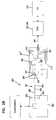
- FIG. 1is a schematic view of a fiber optic network in accordance with the principles of the present disclosure
- FIG. 2is a schematic drawing of an example fiber distribution hub that can be used in the fiber optic network of FIG. 1 ;
- FIG. 3is a front, bottom perspective view of a drop terminal that can be used in the fiber optic network of FIG. 1 ;
- FIG. 4is a front view of the drop terminal of FIG. 3 ;
- FIG. 5is a side view of the drop terminal of FIG. 3 ;
- FIG. 6is an exploded, perspective view of the drop terminal of FIG. 3 ;
- FIG. 7is a view showing the interior of a front piece of the drop terminal of FIG. 3 ;
- FIG. 8is another view showing the interior of the front piece of the drop terminal of FIG. 3 ;
- FIG. 9is a perspective, partial cross-sectional view showing a fiber optic adapter and fiber optic connector that can be used with the drop terminal of FIG. 3 ;
- FIG. 10is a schematic view of a first cable configuration between a drop terminal, a network interface device and a wireless transceiver;
- FIG. 11is a cross-sectional view taken along section line 11 - 11 of FIG. 10 showing an example trunk section that can be used in the cable configuration of FIG. 10 ;
- FIG. 12is a cross-sectional view taken along section line 11 - 11 of FIG. 10 showing an alternative trunk section for the cable configuration of FIG. 10 ;
- FIG. 13is a cross-sectional view taken along section line 11 - 11 of FIG. 10 showing another trunk section that can be used with the cable configuration of FIG. 10 ;
- FIG. 14is a cross-sectional view taken along section line 14 - 14 of FIG. 10 showing an example branch section for the cable configuration of FIG. 10 ;
- FIG. 15is a cross-sectional view taken along section line 14 - 14 of FIG. 10 showing an alternative branch section for the cable configuration of FIG. 10 ;
- FIG. 16is a cross-sectional view taken along section line 14 - 14 of FIG. 10 showing still another branch section that can be used with the cable configuration of FIG. 10 ;
- FIG. 17is a cross-sectional view taken along section line 17 - 17 of FIG. 10 showing another branch section for the cable configuration of FIG. 10 ;
- FIG. 18is a cross-sectional view taken along section line 17 - 17 of FIG. 10 showing a further branch section that can be used for the cable configuration of FIG. 10 ;
- FIG. 19shows a second cable configuration for providing an interconnection between a drop terminal, a network interface device and a wireless transceiver
- FIG. 20is a cross-sectional view taken along section line 20 - 20 of FIG. 19 showing an example cable arrangement for a trunk section of the cable configuration of FIG. 15 ;
- FIG. 21is a cross-sectional view taken along section line 20 - 20 of FIG. 19 showing an alternative trunk section for the cable configuration of FIG. 19 ;
- FIG. 22is a cross-sectional view taken along section line 22 - 22 of FIG. 19 showing an example branch cable arrangement for the cable configuration of FIG. 19 ;
- FIG. 23is a cross-sectional view taken along section line 19 - 19 showing an alternative branch cable configuration that can be used for the cable configuration of FIG. 19 ;
- FIG. 24is a third cable configuration for providing connections between a drop terminal, a network interface device and a wireless transceiver;
- FIG. 25is a schematic view showing a fourth cable configuration for providing connections between a drop terminal, a network interface device and a wireless transceiver;
- FIG. 26is a cross-sectional view of an example fiber optic adapter that can be used on the drop terminal, the wireless transceiver and the network interface device of FIG. 25 ;
- FIG. 27is a cross-sectional view showing a ruggedized fiber optic connector that can be inserted in an exterior port of the fiber optic adapter of FIG. 26 ;
- FIG. 28is a schematic view of a fifth cable configuration for interconnecting a drop terminal, a wireless transceiver and a network interface device.
- FIG. 1illustrates an exemplary passive optical network 100 .
- the network 100is adapted to interconnect a central office 110 to a number of end subscribers 115 (also called end users 115 herein).
- the central office 110may additionally connect to a larger network such as the Internet (not shown) and a public switched telephone network (PSTN).
- PSTNpublic switched telephone network
- the various lines of the networkcan be aerial or housed within underground conduits (e.g., see conduit 105 ).
- the network 100includes feeder distribution cables 120 routed from the central office 110 .
- the feeder distribution cables 120often include a main cable or trunk, and a plurality of branch cables that branch from the main cable.
- the portion of network 100 that is closest to central office 110is generally referred to as the F1 region.
- the F1 region of the networkmay include a feeder cable (i.e., an F1 distribution cable) having on the order of 12 to 48 fibers; however, alternative implementations may include fewer or more fibers.
- the network 100also has an F2 region that includes cables and components located in closer proximity to the subscribers/end users 115 .
- the network 100also may include fiber distribution hubs (FDHs) 130 that receive branch cables of the feeder distribution cable 120 and that output one or more F2 distribution cables 122 .
- FDHsfiber distribution hubs
- an FDH 130is an equipment enclosure that may include a plurality of passive optical splitters (e.g., 1-to-8 splitters, 1-to-16 splitters, or 1-to-32 splitters) for splitting the incoming feeder fibers into a number (e.g., 216, 432, etc.) of output distribution fibers corresponding to optical fibers of the F2 distribution cables 122 .
- the F2 distribution cablesare routed from the FDH 130 to locations in close proximity to the end users 115 .
- the F2 distribution cables 122can have a variety of different type of configurations. As depicted at FIG. 1 , the F2 distribution cables include a plurality of breakout locations 116 at which branch cables (e.g., drop cables, stub cables, etc.) are separated out from and optically coupled to trunks of the distribution cables 122 . Breakout locations 116 also can be referred to as tap locations or branch locations and branch cables also can be referred to as breakout cables or tethers. At a breakout location, fibers of the trunk of the distribution cable can be broken out and connectorized to form a connectorized tether. In other embodiments, fibers of the trunk can be broken out and spliced to a length of optical fiber having a connectorized free end so as to form a connectorized tether.
- branch cablese.g., drop cables, stub cables, etc.
- Stub cablesare typically branch cables that are routed from breakout locations 116 to intermediate access locations, such as a pedestals, drop terminals 104 or hubs. Intermediate access locations can provide connector interfaces located between breakout locations 116 and the subscriber locations 115 .
- a drop cableis a cable that typically forms the last leg to a subscriber location 115 .
- drop cablescan be routed from intermediate access locations to subscriber locations 115 . Drop cables also can be routed directly from breakout locations 116 to subscriber locations 115 , thereby bypassing any intermediate access locations.
- F2 distribution cablemay not employ breakouts. Instead, an F2 distribution cable may be run from an FDH to a drop terminal such that one end of the F2 distribution cable is located at the FDH and the other end of the F2 distribution cable is located at the drop terminal.
- the F2 distribution cablemay include the same number of optical fibers as the number of access ports provided on the drop terminal.
- an excess length of the F2 distribution cablecan be stored on a spool provided at the drop terminal as described at U.S. Patent Application Ser. No. 61/098,494, which is hereby incorporated by reference.
- FIG. 1shows the network after installation of the distribution cables and drop terminals, but before installation of drop cables.
- drop cableswill typically be installed to form the final legs between the subscribers 115 and the intermediate locations (e.g., drop terminals 104 ) or between the subscribers 115 and the break out locations 116 .
- the depicted networkis configured to allow service to be distributed to the network via wireless transmissions as well as hard connections (i.e., connections made to the network through a direct physical connection such as a co-axial cable, twisted pair cable, fiber optic cable or other type of cable).
- Wireless transmissionsallow service to be provided to subscribers that are not hard connected to the network and also allow redundant service to be provided to subscribers that are hard connected to the network.
- a wireless transceiver 132 Ais installed adjacent FDH 130 A.
- the wireless transceiver 132 Acan be mounted inside the enclosure of the FDH 130 A, or can be outside the enclosure of the FDH 130 A.
- the wireless transceiver 132 Ahas a coverage area 134 A large enough to cover at least the portion of the network to which the FDH 130 A provides hard service connections. In certain embodiments, the wireless transceiver 132 A has a coverage area larger than the portion of the network to which the FDH 130 A provides hard service connections.
- Power for the wireless transceiver 132 Acan be provided from a number of sources. For example, power can be metered from an adjacent utility. Alternatively, power can be provided by a battery located at or near the FDH 130 A. Further, power can be provided by a solar panel 136 positioned on, at, or near the FDH 130 A. In certain embodiments, the solar panel 136 can be used to re-charge a battery within the FDH enclosure that provides power to the wireless transceiver 132 A.
- wireless transceivers 132 Bare also mounted at or near the drop terminals 104 of the network.
- the wireless transceivers 132 Bhave coverage areas 134 B smaller than the coverage area 134 A of the wireless transceiver 132 A.
- the coverage areas 134 Bare shown within the coverage area 134 A and each coverage area 134 B corresponds in size generally with the portion of the network to which it corresponding drop terminals 104 is intended to provide hard service connections.
- the wireless transceivers 132 Binclude components for converting optical signals and/or electrical signals to wireless signals.
- the wireless transceivers 132 Bfurther includes components for transmitting the wireless signals to a predetermined transmission area, and for receiving wireless signals transmitted from transmitters within the wireless service area.
- the wireless transceivercan also include multiplexers or other equipment.
- FIG. 2is a schematic diagram showing an example lay out that can be used for the FDHs 130 , 130 A in the network of FIG. 1 .
- Each FDH 130 , 130 Agenerally administers connections at a termination region 211 between incoming fibers and outgoing fibers in an Outside Plant (OSP) environment.
- OSPOutside Plant
- a connectionbetween fibers includes both direct and indirect connections.
- incoming fibersinclude fibers from a feeder cable 202 that enter the FDH 130 , 130 A and intermediate fibers (e.g., connectorized pigtails 208 extending from splitters 250 and patching fibers/jumpers) that connect the fibers of the feeder cable 202 to the termination region 211 .
- Examples of outgoing fibersinclude fibers of a subscriber cable 212 (e.g., fibers of F2 distribution cables) that exit the FDH 130 , 130 A and any intermediate fibers that connect the fibers of the subscriber cable 212 fibers to the termination region 211 .
- the FDH 130 , 130 Aprovides an interconnect interface for optical transmission signals at a location in the network where operational access and reconfiguration are desired.
- the FDH 130 , 130 Acan be used to split the signals from the feeder cables 202 and direct the split signals to the fiber of the distribution cables 212 routed to subscriber locations 115 .
- the FDH 130 , 130 Ais designed to accommodate a range of alternative sizes and fiber counts and support factory installation of pigtails 208 , fanouts, and splitter modules 250 .
- the feeder cable 202is initially routed into the example FDH 130 through an enclosure/cabinet 201 (e.g., typically through the back or bottom of the cabinet 201 ).
- the fibers of the feeder cable 202can include ribbon fibers.
- An example feeder cable 202may include twelve to forty-eight individual fibers connected to the service provider's central office 110 .
- the fibers of the feeder cable 202are routed to a feeder cable interface 280 (e.g., fiber optic adapter modules, a splice tray, etc.).
- each splitter module 250includes at least one fiber optic splitter 251 positioned within a splitter housing 253 .
- the splitter input fibers 206are optically connected to separate splitter modules 250 , wherein the input fibers 206 are each split by the fiber optic splitters 251 of the splitter modules 250 into multiple pigtails 208 , each having a connectorized end 210 .
- the termination region 211 , the splitter mounting region 222 a , storage region 213 and the feeder cable interface 280can all be mounted on a swing frame/chassis 230 mounted within the cabinet 201 .
- the chassis 230is pivotally movable relative to the cabinet 201 between a stowed position in which the chassis 230 is fully within the cabinet 201 and an access position in which the chassis 230 projects at least partially outside the cabinet 201 .
- the pivotal configuration of the chassis 230allows the various components carried by the chassis 230 to be more easily accessed.
- the connectorized ends 210can be temporarily stored on a storage module 260 that is mounted at the storage region 213 of the swing frame 230 .
- the pigtails 208are routed from the splitter modules 250 to a termination module 240 that is provided at the termination region 211 of the swing frame 230 .
- the connectorized ends 210 of the pigtails 208are connected to connectorized ends 214 of the fibers of the distribution cable 212 by fiber optic adapters 245 .
- the termination region 211is the dividing line between the incoming fibers and the outgoing fibers.
- a typical distribution cable 212forms the F2 portion of a network (see FIG.
- Example FDHsare disclosed at U.S. patent application Ser. Nos. 11/544,951 and 12/241,576 that are hereby incorporated by reference.
- the splitter modules 250 and storage modules 260can be incrementally added to the swing frame 230 .
- the connectorized pigtails 208are typically stored in one or more of the storage modules 260 prior to installation on the swing frame 230 .
- the connector 210 of each pigtail 208is secured in one of the storage modules 260 before the splitter module 250 leaves the factory.
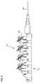
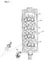
- FIGS. 3-8show an example configuration for the drop terminals 104 used in the network of FIG. 1 .
- the drop terminal configurationincludes a housing 352 having a back piece 354 and a front piece 356 that cooperate to enclose an interior region 357 (shown at FIG. 6 where the back piece 354 has been removed from the front piece 356 ).
- a plurality of fiber optic adapters 358are mounted to the front piece 356 .
- the adapters 358include exterior ports 360 that are accessible from the outside of the housing 352 . In use, connectorized ends of drop cables can be inserted into the exterior ports 360 to connect the drop cables to the network.
- the exterior ports 360are enclosed by plugs 362 when not connected to drop cables.
- the fiber optic adapters 358also include interior ports 364 that are accessible from inside the housing 352 .
- the interior ports 364receive interior fiber optic connectors 366 (e.g., standard SC connectors as disclosed at U.S. Pat. No. 5,317,663, which is hereby incorporated by reference) that are mounted to the ends of fibers 371 corresponding to a fiber optic cable 367 (e.g., a branch cable from an F2 trunk) that is routed into the interior of the housing 352 .
- a fiber optic cable 367e.g., a branch cable from an F2 trunk
- FIG. 8for clarity, the routing paths for only two of the fibers 371 are shown. In practice, fibers 371 will be routed to each of the interior fiber optic connectors 366 of the drop terminal 104 .
- the fibers 371are optically coupled to corresponding fibers of the cable 367 .
- the fibers 271can be integral continuations of the fibers of the cable 367 or can be spliced to the fibers of the cable 367 . Further details about the drop terminal configuration can be found in U.S. application Ser. No. 12/248,564, which is hereby incorporated by reference in its entirety.
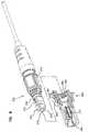
- FIG. 9is a partial cross-sectional view showing one of the fiber optic adapters 358 and a corresponding exterior fiber optic connector 372 adapted to be received within the exterior port 360 of the adapter 358 .
- the exterior fiber optic connector 372includes a connector body 373 having a distal end portion 374 at which a ferrule 375 is mounted.
- the ferrule 375supports and end portion of an optical fiber 376 of a cable (e.g., a drop cable) to which the fiber optic connector 372 is attached.
- a cablee.g., a drop cable
- the alignment sleeve 377also receives a ferrule of the interior connector 366 inserted within the interior port 364 of the fiber optic adapter 358 . In this way, the alignment sleeve 377 provides alignment between the fiber 376 of the exterior fiber optic connector 372 and the fiber 371 of the interior fiber optic connector 366 thereby providing an optical connection that allows optical signals can be transferred between the fibers 376 , 371 .
- An o-ring 378is mounted about the connector body 373 and forms an environmental seal between the connector body 373 and the fiber optic adapter 358 when the exterior fiber optic connector 372 is mounted within the exterior port 360 .
- the exterior fiber optic connector 372can be retained within the exterior port 360 by a threaded fastener 379 that threads into internal threads 380 defined within the exterior port 360 .
- the fiber optic adapter 358also includes a sealing member 381 (e.g., a o-ring) that provides an environmental seal between the exterior of the fiber optic adapter 358 and the front piece 356 of the drop terminal 104 when the adapter 358 is mounted within an opening defined by the front piece 356 .
- a nut 383can be used to secure the adapter 358 to the front piece 356 of the drop terminal 104 . Further details of the fiber optic adapter 358 and the exterior fiber optic connector 372 are disclosed at U.S. application Ser. No. 12/203,508, which is hereby incorporated by reference.
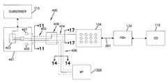
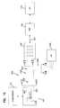
- FIG. 10shows an example cabling configuration 400 used to provide power and network connections to one of the wireless transmitters 132 B of the network of FIG. 1 .
- the cabling configuration 400provides an optical signal feed from one of the drop terminals 104 to an ONT 401 positioned at the subscriber location 115 .
- the drop terminal 104can be optically connected to one of the FDHs 130 A (e.g., by an F2 distribution cable such as cable 367 ) which is optically connected to the central office 110 .
- the ONT 401includes a converter 403 that converts fiber optic signals to Ethernet signals and that converts Ethernet signals back to fiber optic signals.
- the ONT 401also typically includes other signal processing equipment (e.g., a multiplexer) in addition to the converter 403 .
- the optical signal feedis split before being converted at the converter 403 .
- the split fiber optic signal feedsare converted to Ethernet signal feeds at the converter 403 .
- One of the converted signal feedsis provided to the subscriber 115 while the other converted signal feed is back fed through the cabling configuration 400 to the wireless transceiver 132 B.
- the cabling configuration 400is also used to provide a power connection between a power source 405 at the ONT 401 and the wireless transceiver 132 B.
- the cabling configuration 400can also provide a ground connection between the wireless transceiver 132 B and a ground location 407 at the ONT 401 .
- the Ethernet signalmay be split.
- multiple fiber optic linesmay be routed to the ONT 401 thereby eliminating the need for signal splitting.
- the cabling configuration 400includes a bifurcated cable having a trunk section 402 and two branch sections 404 , 406 .
- the branch sections 404 , 406are connected to the trunk section 402 at a furcation member 408 .
- the trunk 402is capable of transmitting twisted pair Ethernet signals and fiber optic signals.
- the trunk 402also include power and ground lines.
- the branch section 404is adapted for carrying fiber optic signals.
- the branch section 406is adapted for carrying twisted pair Ethernet signals and also includes power and ground lines.
- FIGS. 11-13show several different cable arrangements that can be used for the trunk section 402 of the cabling configuration 400 .
- the views of FIGS. 11-13are taken along cross section line 11 - 11 of FIG. 10 .
- cable arrangement 402 Aincludes four twisted wire pairs 410 .
- Each twisted wire pair 410includes two wires that are twisted relative to one another about a common axis.
- Each of the wiresincludes a central conductor (e.g., a copper conductor) and an insulation layer surrounding the central conductor.
- co-axial cablecould be used in place of the twisted pair wires. Referring still to FIG.
- the cable configuration 402 Aalso includes an optical fiber 412 , a dedicated power line 414 and a dedicated ground line 415 .
- the optical fibercan include a bend sensitive optical fiber having an outer diameter of about 250 microns.
- the optical fibercan be loosely or tightly buffered.
- a tight buffer layer having an outer diameter of about 900 micronsis provided over the optical fiber.
- the power line 414 and ground line 415are used to transfer power between the power source 405 and active components of the wireless transceiver 132 B.
- the twisted wire pairs 410are used to convey Ethernet signals between the ONT 401 and the wireless transmitter 132 B.
- the optical fiber 412is used to convey fiber optic signals between the drop terminal 104 and the ONT 401 .
- the cable arrangement 402 Aalso includes a spacer 416 for separating the various wires/fibers of the cable arrangement.
- the spacer and the wires/fiberstogether form a core of the cable arrangement 402 A.
- a strength layer 418is positioned around the core.
- the strength layer 418includes tensile reinforcing members such as aramid yarn.
- the cable arrangement 402 Aalso includes an outer jacket 420 that surrounds the strength layer 418 .
- the spacer 416functions to position and maintain separation between the components forming the core of the cable configurations.
- the depicted spacer 416defines a plurality separate pockets for receiving components such as twisted wire pairs, fibers and power/ground lines.
- cables in accordance with the principles of the present disclosuremay include tape spacers (e.g., tape dividers/separators).
- cable arrangements in accordance with the principles of the present disclosuremay not use spacers.
- the cable arrangement 402 B of FIG. 12is the same as the cable arrangement 402 A of FIG. 11 except no dedicated power or ground lines are provided within the cable arrangement 402 B. Instead, power is carried through the cable arrangement 402 B along selected ones of the twisted wire pairs 410 .
- the cable arrangement 402 C of FIG. 13also includes four twisted wire pairs 410 and optical fiber 412 .
- the cable arrangement 402 Chas a modified spacer 416 ′ within which a central strength member 417 is located.
- the central strength member 417preferably provides tensile reinforcement to the cable arrangement 402 C.
- the central strength member 417is made of a metal material such as steel.
- the cable arrangement 402 Calso includes a conductive layer 419 that surrounds the inner cable core.
- the conductive layer 419can include a braid of material such as aramid yarn and metal strands (e.g., copper strands). In other embodiments, the conductive layer 419 can be formed by a layer of conductive tape. In one embodiment, the central strength member 417 can be used as a power line for providing power to the wireless transceiver 132 B and the conductive layer 419 can be used as a ground line. The outer jacket 420 surrounds the conductive layer 419 .
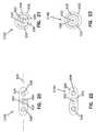
- Example cable arrangements 406 A- 406 C for the branch section 406are shown at FIGS. 14-16 .
- the views of FIGS. 14-16are taken along section line 14 - 14 of FIG. 10 .
- the cable arrangement 406 Ais the same as the cable arrangement 402 A of FIG. 11 except the optical fiber 412 is not present.
- the cable arrangement 406 B of FIG. 15is the same as the cable arrangement 402 B of FIG. 12 except the optical fiber 412 is not present.
- the cable arrangement 406 C of FIG. 16is the same as the cable arrangement 402 C of FIG. 13 except the optical fiber 412 is not present.
- the optical fiber 412is not present in the cable arrangements 406 A- 406 C of FIGS.
- the branch section 404preferably has an arrangement suitable for protecting the optical fiber 412 .
- the optical fiber 412can have a connectorized end (e.g., a connector such as the connector 372 of FIG. 9 ) that can be readily inserted into one of the exterior ports 360 of the drop terminal 104 . By inserting the connectorized end into the exterior port 360 , an optical connection is made between the optical fiber 412 and one of the optical fibers 371 (shown at FIG. 8 ) of the fiber optic cable 367 routed to the drop terminal 104 .
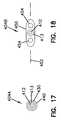
- FIGS. 17 and 18show example cable arrangements 404 A, 404 B suitable for use as the branch section 404 of the cable configuration 400 of FIG. 10 .
- the optical fiber 412is surrounded by a buffer layer (e.g., a tight buffer layer or a loose buffer tube) which in turn is surrounded by a strength layer 430 .
- the strength layer 430provides tensile reinforcement to the cable arrangement 404 A and can include a plurality of flexible reinforcing members such as aramid yarns.
- the strength layer 430is surrounded by an outer jacket 440 .
- the strength layer 430can be anchored at one end of the branch section 404 to a connectorized end of the optical fiber 412 and can be anchored at the other end of the branch section 404 to the furcation member 408 .
- the optical fiber 412 and buffer layer 413are surrounded by an outer jacket 450 having a transverse cross section that is elongated along an axis 452 .
- the optical fiber 412is centered generally on the axis 452 .
- strength members 454are positioned on the axis 452 on opposite sides of the optical fiber 412 .
- the strength members 454are embedded within the jacket 450 and are parallel to the optical fiber 412 .
- the strength members 454preferably provide tensile reinforcement to the cable arrangement 404 B.
- each of the strength membersincludes a rod formed by fiber glass reinforced epoxy. Similar to the strength layer 430 of the cable arrangement 404 A of FIG. 12 , the strength members 454 can be anchored at one end of the branch section 404 to the furcation member 408 and at the other end of the branch section 404 can be anchored to the connectorized end of the optical fiber 412 .
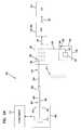
- FIG. 19depicts another cabling configuration 500 for back feeding telecommunications service and power from an ONT 502 to one of the wireless transceivers 132 B of the network of FIG. 1 .
- distribution cable 367is routed from FDH 130 , 130 A to one of the drop terminals 104 .
- An optical signal provided to drop terminal 104 by the distribution cable 367is directed from an exterior port 360 of one of the fiber optic adapters 358 of the drop terminal 104 through the cabling configuration 500 to the ONT 502 .
- the optical signalis split at splitter 503 .
- One output from the splitter 503is directed to one or more components 504 of the ONT (e.g., an active component such as a converter and other equipment such as a multiplexer) and is then routed to the subscriber 115 .
- the other output from the splitter 503is back fed through the cabling configuration 500 to the wireless transceiver 132 B.
- the cabling configuration 500also electrically connects the wireless transceiver 132 B to a power source 505 and a ground location 507 of the ONT 502 .
- the cabling configuration 500includes a trunk section 510 , a furcation member 512 and two branch sections 514 , 516 .
- the cabling configuration 500includes a first optical transmission path 517 that extends from the drop terminal 104 through the branch section 514 , the furcation member 512 and the trunk section 510 to the ONT 502 .
- the cabling configuration 500also includes a second optical transmission path 519 that extends from the wireless transceiver 132 B through branch section 516 , furcation member 512 and trunk section 510 to the ONT 502 .
- the cabling configuration 500further includes a power line 521 and a grounding line 523 that extend from the ONT 502 through the trunk section 510 , the furcation member 512 and the branch section 516 to the wireless transceiver 132 B.
- FIGS. 20 and 21show example cable arrangements 510 A, 510 B (i.e., cable assemblies) that can be used for the trunk section 510 of the cabling configuration 500 .
- the views of the FIGS. 20 and 21are taken along cross section line 20 - 20 of FIG. 19 .
- the cable arrangement 510 Aincludes optical fibers 520 positioned within a buffer tube 522 .
- the buffer tube 522is encased within an outer jacket 524 . When viewed in transverse cross section, the outer jacket 524 is elongated along an axis 526 .
- the buffer tube 522is centered on the axis 526 .
- the cable arrangement 510 Aalso includes two strength members 528 aligned along the axis 526 on opposite sides of the buffer tube 522 .
- the strength members 528preferably provide tensile reinforcement to the cable arrangement 510 A and are preferably generally parallel to the buffer tube 522 .
- at least portions of the strength members 528are electrically conductive.
- the strength members 528have a metal construction such as steel.
- the strength members 528can include a steel construction with an outer conductive coating such as copper.
- the strength members 528can include fiber glass reinforced epoxy rods that are coated with a conductive layer such as copper.
- the cable arrangement 510 B of FIG. 21includes buffer tube 522 surrounding optical fibers 520 .
- the cable configuration 510also includes a strength layer 530 that surrounds the buffer tube 522 and provides tensile reinforcement to the cable arrangement 510 B.
- the strength layeris formed by a plurality of aramid yarns.
- An outer jacket 532surrounds the strength layer 530 .
- Conductive members 533 , 535are positioned inside the jacket 532 .
- FIGS. 22 and 23show example cable arrangements 516 A, 516 B that can be used for the branch section 516 of the cabling configuration 500 .
- the cable arrangement 516 A of FIG. 22is the same as the cable arrangement of 510 A of FIG. 20 except one of the fibers 520 is not present.
- the cable arrangement 516 B of FIG. 23is the same as the cable arrangement 510 B of FIG. 121 except one of the fibers 520 is not present.
- the branch section 514can have a cable arrangement suitable for protecting an optical fiber such as the cable arrangements of FIGS. 17 and 18 .
- the cable arrangement forming the trunk section 510extends from the ONT 502 through the furcation member 512 and then along the branch section 516 .
- one of the fibers 522is broken out from the trunk section 510 and directed along branch section 514 .
- one of the fibers 520 of the cabling configuration 500extends from the ONT 502 along the trunk section 510 , through the furcation 512 , along the branch section 516 to the wireless transmitter 132 A to provide the second optical path 519 .
- the other optical fiber 520extends from the ONT 502 along the trunk section 510 , through the furcation member 512 , along the branch 514 to the drop terminal 104 to form the first optical path 517 .
- the branch 514can be terminated by a connector (e.g., a connector such as the connector 372 of FIG. 9 ) that is inserted in the exterior port 360 of one of the fiber optic adapters 358 of the drop terminal 104 to provide an optical connection with the FDH and the central office 110 .
- the reinforcing members 528extend from the ONT 502 along the trunk section 510 through the furcation member 512 , along the branch section 516 to the wireless transceiver 132 A to form the power and grounding lines 521 , 523 between the wireless transceiver 132 A and the power source 505 and grounding location 507 at the ONT 502 . Because the strength members 528 have electrically conductive properties, the strength members 528 can serve the dual function of reinforcing the cable assembly 500 and also providing a power connection between the ONT 502 and the wireless transceiver.
- FIG. 24shows a cabling configuration 600 for feeding power from an ONT 602 to a wireless transceiver 132 C.
- the cabling configuration 600includes an optical transmission path 604 that extends from the exterior ports 360 of one of the fiber optic adapters 358 of drop terminal 104 to the ONT 602 .
- the cabling configuration 600also includes a power line 605 and a grounding line 606 that extend from the ONT 602 to the wireless transceiver 132 C.
- the optical transmission path 604 and the power and grounding lines 605 , 606are grouped together along a trunk section 607 of the cabling configuration 600 .
- the optical transmission path 604separates from the power and grounding lines 605 , 606 at furcation member 609 such that the optical transmission path 604 extends along a first branch section 610 of the cabling configuration 600 and the power and grounding lines 605 , 606 extend along a second branch section 611 of the cabling configuration 600 .
- the optical transmission path 604allows fiber optic telecommunications service to be provided to the subscriber 115 through the ONT 602 .
- the branch section 610can include a connectorized end (e.g., provided by a connector such as the connector 372 of FIG. 9 ) that is inserted in the exterior port 360 of one of the fiber optic adapters 358 of the drop terminal 104 .
- various active and passive components 613can be provided within the ONT 602 for converting the optical signal to an Ethernet signal, and for providing multiplexing capabilities.
- the power line 605is connected to a power source 603 located at the ONT 602 and the grounding line 606 is connected to a ground location 605 at the ONT 602 .
- the wireless transceiver 132 Cincludes an outer housing 620 in which active transceiver components 621 of the transceiver are housed. At least one of the fiber optic adapters 358 is mounted to the outer housing 620 .
- the exterior port 360 of the fiber optic adapter 358is accessible from outside the housing 620 while the interior port 364 can receive the connectorized end of an optical fiber 623 routed from the fiber optic adapter 358 to the active transceiver component or components 621 within the housing 620 (e.g., transceiving equipment).
- a cable 630is used to provide an optical transmission path between the drop terminal 104 and the wireless transceiver 132 C.
- the cable 630can include an optical fiber having connectorized ends inserted respectively in one of the exterior ports 360 of the drop terminal 104 and in the exterior port 360 of the wireless transceiver 132 C.
- the connectorized ends of the cablecan include connectors such as the connector 372 of FIG. 9 .
- the wireless transceiver component 621is placed in optical communication with the central office 110 via an optical transmission path that extends through fiber 623 to the cable 630 , through the cable 630 to the drop terminal 104 , through internal fibers 371 of the drop terminal to cable 367 , through cable 367 to FDH 130 , 130 A, and through F2 cable 120 from FDH 130 , 130 A to the central office 110 .
- FIG. 25shows a cabling configuration 700 including a first cable 701 and a second cable 703 .
- the first cable 701provides an optical transmission path 750 , a power line 751 and a grounding line 752 between an ONT 702 and a drop terminal 104 ′.
- the power and grounding lines 751 , 752are respectively connected to a power source 790 and a ground location 791 at the ONT 702 .
- the second cable 703provides an optical transmission path 754 , a power line 755 and a grounding line 756 between the drop terminal 104 ′ and a wireless transceiver 132 D.
- the drop terminal 104 ′includes a plurality of the fiber optic adapters 258 mounted to an outer housing of the drop terminal 104 ′.
- the drop terminal 104 ′also includes a plurality of modified fiber optic adapters 258 ′ (shown at FIG. 26 ) having interior ports 364 ′ and exterior ports 360 ′.
- the fiber optic adapters 358 ′have the same configuration as the fiber optic adapter 358 shown at FIG. 9 except exterior ports 360 ′ of the adapters 358 ′ have been modified to include power contacts 390 ′ and ground contacts 391 ′.
- the interior ports 364 ′receive internal fiber optic connectors corresponding to fibers of distribution cable 367 routed from the FDH 130 , 130 A to the drop terminal 104 ′.
- the power contacts 320 ′ and the ground contacts 321 ′are positioned at opposite sides of an alignment sleeve 377 ′ of the fiber optic adapter 358 ′.
- a first circuit path 760is provided within the drop terminal 104 ′ for electrically connecting the power contacts 320 ′ of the fiber optic adapters 258 ′.
- the drop terminal 104 ′also includes a second circuit path 762 for electrically connecting the ground contacts 321 ′ of the fiber optic adapters 258 ′.
- the contacts 320 ′, 321 ′can respectively include exterior tabs 323 ′, 325 ′ for facilitating connecting the contacts 320 ′, 321 ′ to their respective circuit paths 760 , 762 .
- the first and second circuit paths 760 , 762can be provided on a circuit board mounted within the drop terminal 104 ′.
- FIG. 27an example connector 390 ′ adapted to interface with the exterior ports 360 ′ of the fiber optic adapters 358 ′ is depicted.
- the connector 390 ′has substantially the same configuration as the connector 372 with the addition of a power lead 391 ′ and a ground lead 392 ′.
- the connector 390 ′includes a connector body 394 ′ supporting a ferrule 395 ′.
- the power and ground leads 391 ′, 392 ′are positioned on opposite sides of the ferrule 395 ′.
- the connector 390 ′is shown connected to the end of the first cable 701 .
- the first cableis shown having the same configuration as the cable 516 A of FIG. 22 .
- the power lead 391 ′is electrically connected to one of the conductive strength members 528 of the cable 701 while the ground lead 392 ′ is electrically connected to the other conductive strength member 528 of the cable 701 .
- the conductive strength members 528respectively electrically connect the power and ground leads 391 ′, 392 ′ to the power source 790 and grounding location 791 at the ONT 702 .
- the ferrule 395 ′fits within the alignment sleeve 377 ′, the power lead 391 ′ engages the power contact 320 ′ and the ground lead 392 ′ engages the ground contact 321 ′.
- the fiber within the cable 701is optically connected to one of the optical fibers of the distribution cable 367 routed from the drop terminal 104 ′ to the FDH 130 , 130 A.
- the interface between the connector 390 ′ and the adapter 358 ′also provides an electrical connection between the power source 790 (which is electrically connected to the power lead 391 ′) and the first circuit path 760 .
- the first circuit path 760provides power to the power contact 320 ′ of the other adapter 358 ′ of the drop terminal 104 ′.
- the interface between the connector 390 ′ and the adapter 358 ′further provides an electrical connection between the ground location 791 (which is electrically connected to the ground lead 392 ′) and the second circuit path 762 .
- the second circuit path 762grounds the ground contact 321 ′ of the other adapters 358 ′ of the drop terminal 104 ′.
- more than two of the adapters 358 ′can be provided on the drop terminal 104 ′ and linked to remote power and grounding locations.
- the adapter 358 ′ and connector 390 ′ interfacecan also be used at other locations where it is desired to connect power/ground and a fiber optic line through the same connector arrangement.
- the adapter 358 ′ and the connector 390 ′can be used at the interface between the first cable 701 and the ONT 702 of FIG. 25 .
- the adapter 358 ′ and the connector 390 ′can be used at the interface between the trunk section 607 and the ONT 602 of FIG. 24 .
- the adapter 358 ′ and the connector 390 ′can be used at the interface between the wireless transceiver 132 B and the branch section 516 of FIG. 19 .
- the adapter 358 ′ and connector 390 ′can be modified to have a multi-fiber ferrule and alignment sleeve configuration and used at the interface between the trunk 510 and the ONT 502 of FIG. 19 .
- the wireless transceiver 132 Dincludes at least one of the fiber optic adapters 358 ′ mounted to an exterior wall of an outer enclosure/housing 780 of the wireless transceiver 132 D.
- the power contact 320 ′ and the ground contact 321 ′ of the fiber optic adapter 358 ′are preferably electrically connected by circuit paths 770 , 771 to active transceiver components 764 located within the housing 780 of the wireless transceiver 132 D.
- An internal optical fiber 766extends from the active transceiver components 764 to a fiber optic connector mounted within the interior port 364 ′ of the fiber optic adapter 258 ′.
- the second cable 703is used to provide an optical transmission path and a power transmission path between the drop terminal 104 ′ and the wireless transceiver 132 D.
- the second cable 703can have the same configuration as the first cable 701 used to connect the drop terminal 104 ′ to the ONT 702 .
- the cable 702can have each end connectorized with one of the connectors 390 ′ and can have a cable configuration of the type shown by the cable 516 A of FIG. 22 .
- the connectorized ends of the second cable 703are preferably inserted within corresponding exterior ports 360 ′ of the drop terminal 104 ′ and the wireless transceiver 132 D.
- the internal optical fiber 766 of the wireless transceiver 132 Dis optically connected to one of the fibers of the distribution cable 367 that extends from the drop terminal 104 ′ to the FDH 130 , 130 A.
- the active transceiver components 764are electrically connected to the power source 790 and grounding location 791 of the ONT 702 .
- the grounding and power pathwaysextend through the first cable 701 from the ONT 702 to a first one of the adapters 358 ′, through the circuit paths 760 , 762 to a second one of the adapters 358 ′, through the second cable 703 to the contacts 320 ′, 321 ′ of the adapter 358 ′ on the wireless transceiver 132 D, and then through the circuit paths 770 , 771 to the active transceiver components 764 .
- FIG. 28shows a cabling system 800 having a cable 801 that provides an optical transmission line 803 , a power transmission line 805 and a ground line 807 between an ONT 802 and a drop terminal 104 ′′.
- the cable 801can have the same configuration as the first cable 701 of FIG. 25 and can include connectorized ends including connectors 390 ′ that interface with adapters 358 ′ provided at the ONT 802 and at the drop terminal 104 ′′.
- the power and ground contacts 320 ′, 321 ′ of the adapter 358 ′ at the ONT 802can be respectively connected to a power source 830 and a ground location 832 .
- the drop terminal 104 ′′has the same configuration as the drop terminal 104 ′ except an active wireless transceiver component 810 is mounted within an outer housing 812 of the drop terminal 104 ′′.
- One or more optical fibers from distribution cable 367 routed from the FDH 130 , 130 A to the drop terminal 104 ′′are optically coupled to the wireless transceiver component 810 within the drop terminal 104 ′′ by one or more internal optical fibers 840 . In this way, one or more fiber optic signals can be routed to the wireless transceiver component 810 from the FDH 130 , 130 A.
- Optical fibers of the distribution cable 367are also linked to interior connectors mounted within the interior ports 364 ′ of the fiber optic adapters 358 ′.
- the wireless transceiver component 810is electrically connected to power and ground contacts 320 ′, 321 ′ of the adapter 358 ′ of the drop terminal 104 ′′ by circuit paths 850 , 851 .
- Grounding and power pathwaysextend through the cable 801 from the ONT 802 to the adapters 358 ′ on the drop terminal 104 ′′, and then from the adapter 358 ′ through the circuit paths 850 , 851 to the wireless transceiver component 810 .
- cabling configurations in accordance with the present disclosuremay include cables that provide power to a wireless transceiver or other wireless device without providing separate grounding lines (e.g., the wireless device may be grounded through other means).
Landscapes
- Physics & Mathematics (AREA)
- General Physics & Mathematics (AREA)
- Optics & Photonics (AREA)
- Engineering & Computer Science (AREA)
- Computer Networks & Wireless Communication (AREA)
- Signal Processing (AREA)
- Electromagnetism (AREA)
- Computing Systems (AREA)
- Light Guides In General And Applications Therefor (AREA)
- Small-Scale Networks (AREA)
Abstract
Description
Claims (20)
Priority Applications (8)
| Application Number | Priority Date | Filing Date | Title |
|---|---|---|---|
| US13/965,928US8929740B2 (en) | 2009-03-05 | 2013-08-13 | Methods, systems and devices for integrating wireless technology into a fiber optic network |
| US14/589,648US9438342B2 (en) | 2009-03-05 | 2015-01-05 | Methods, systems, and devices for integrating wireless technology into a fiber optic network |
| US15/252,908US9893813B2 (en) | 2009-03-05 | 2016-08-31 | Methods, systems, and devices for integrating wireless technology into a fiber optic network |
| US15/616,029US10135534B2 (en) | 2009-03-05 | 2017-06-07 | Methods, systems, and devices for integrating wireless technology into a fiber optic network |
| US16/195,267US10630388B2 (en) | 2009-03-05 | 2018-11-19 | Methods, systems, and devices for integrating wireless technology into a fiber optic network |
| US16/844,216US11044014B2 (en) | 2009-03-05 | 2020-04-09 | Methods, systems, and devices for integrating wireless technology into a fiber optic network |
| US17/350,076US11438070B2 (en) | 2009-03-05 | 2021-06-17 | Methods, systems, and devices for integrating wireless technology into a fiber optic network |
| US17/929,920US12149288B2 (en) | 2009-03-05 | 2022-09-06 | Methods, systems, and devices for integrating wireless technology into a fiber optic network |
Applications Claiming Priority (3)
| Application Number | Priority Date | Filing Date | Title |
|---|---|---|---|
| US15771009P | 2009-03-05 | 2009-03-05 | |
| US12/718,818US8532490B2 (en) | 2009-03-05 | 2010-03-05 | Methods, systems and devices for integrating wireless technology into a fiber optic network |
| US13/965,928US8929740B2 (en) | 2009-03-05 | 2013-08-13 | Methods, systems and devices for integrating wireless technology into a fiber optic network |
Related Parent Applications (1)
| Application Number | Title | Priority Date | Filing Date |
|---|---|---|---|
| US12/718,818ContinuationUS8532490B2 (en) | 2009-03-05 | 2010-03-05 | Methods, systems and devices for integrating wireless technology into a fiber optic network |
Related Child Applications (1)
| Application Number | Title | Priority Date | Filing Date |
|---|---|---|---|
| US14/589,648ContinuationUS9438342B2 (en) | 2009-03-05 | 2015-01-05 | Methods, systems, and devices for integrating wireless technology into a fiber optic network |
Publications (2)
| Publication Number | Publication Date |
|---|---|
| US20140199079A1 US20140199079A1 (en) | 2014-07-17 |
| US8929740B2true US8929740B2 (en) | 2015-01-06 |
Family
ID=42678341
Family Applications (9)
| Application Number | Title | Priority Date | Filing Date |
|---|---|---|---|
| US12/718,818Expired - Fee RelatedUS8532490B2 (en) | 2009-03-05 | 2010-03-05 | Methods, systems and devices for integrating wireless technology into a fiber optic network |
| US13/965,928ActiveUS8929740B2 (en) | 2009-03-05 | 2013-08-13 | Methods, systems and devices for integrating wireless technology into a fiber optic network |
| US14/589,648ActiveUS9438342B2 (en) | 2009-03-05 | 2015-01-05 | Methods, systems, and devices for integrating wireless technology into a fiber optic network |
| US15/252,908ActiveUS9893813B2 (en) | 2009-03-05 | 2016-08-31 | Methods, systems, and devices for integrating wireless technology into a fiber optic network |
| US15/616,029ActiveUS10135534B2 (en) | 2009-03-05 | 2017-06-07 | Methods, systems, and devices for integrating wireless technology into a fiber optic network |
| US16/195,267ActiveUS10630388B2 (en) | 2009-03-05 | 2018-11-19 | Methods, systems, and devices for integrating wireless technology into a fiber optic network |
| US16/844,216ActiveUS11044014B2 (en) | 2009-03-05 | 2020-04-09 | Methods, systems, and devices for integrating wireless technology into a fiber optic network |
| US17/350,076ActiveUS11438070B2 (en) | 2009-03-05 | 2021-06-17 | Methods, systems, and devices for integrating wireless technology into a fiber optic network |
| US17/929,920Active2030-04-24US12149288B2 (en) | 2009-03-05 | 2022-09-06 | Methods, systems, and devices for integrating wireless technology into a fiber optic network |
Family Applications Before (1)
| Application Number | Title | Priority Date | Filing Date |
|---|---|---|---|
| US12/718,818Expired - Fee RelatedUS8532490B2 (en) | 2009-03-05 | 2010-03-05 | Methods, systems and devices for integrating wireless technology into a fiber optic network |
Family Applications After (7)
| Application Number | Title | Priority Date | Filing Date |
|---|---|---|---|
| US14/589,648ActiveUS9438342B2 (en) | 2009-03-05 | 2015-01-05 | Methods, systems, and devices for integrating wireless technology into a fiber optic network |
| US15/252,908ActiveUS9893813B2 (en) | 2009-03-05 | 2016-08-31 | Methods, systems, and devices for integrating wireless technology into a fiber optic network |
| US15/616,029ActiveUS10135534B2 (en) | 2009-03-05 | 2017-06-07 | Methods, systems, and devices for integrating wireless technology into a fiber optic network |
| US16/195,267ActiveUS10630388B2 (en) | 2009-03-05 | 2018-11-19 | Methods, systems, and devices for integrating wireless technology into a fiber optic network |
| US16/844,216ActiveUS11044014B2 (en) | 2009-03-05 | 2020-04-09 | Methods, systems, and devices for integrating wireless technology into a fiber optic network |
| US17/350,076ActiveUS11438070B2 (en) | 2009-03-05 | 2021-06-17 | Methods, systems, and devices for integrating wireless technology into a fiber optic network |
| US17/929,920Active2030-04-24US12149288B2 (en) | 2009-03-05 | 2022-09-06 | Methods, systems, and devices for integrating wireless technology into a fiber optic network |
Country Status (6)
| Country | Link |
|---|---|
| US (9) | US8532490B2 (en) |
| EP (3) | EP2404393B1 (en) |
| CN (3) | CN106130646B (en) |
| BR (1) | BRPI1010245B1 (en) |
| DE (2) | DE202010018543U1 (en) |
| WO (1) | WO2010102201A2 (en) |
Cited By (16)
| Publication number | Priority date | Publication date | Assignee | Title |
|---|---|---|---|---|
| US20150055954A1 (en)* | 2013-08-26 | 2015-02-26 | Adc Telecommunications, Inc. | Wave Division Multiplexer Arrangement for Small Cell Networks |
| US9310578B2 (en) | 2011-10-03 | 2016-04-12 | CommScope Connectivity Belgium BVBA | Enclosure for providing power and data to a remote radio head |
| US9438342B2 (en) | 2009-03-05 | 2016-09-06 | Commscope Technologies Llc | Methods, systems, and devices for integrating wireless technology into a fiber optic network |
| US20160276817A1 (en)* | 2015-03-16 | 2016-09-22 | Commscope Technologies Llc | Enclosure for cable distribution assembly |
| US20160301474A1 (en)* | 2015-04-08 | 2016-10-13 | Corning Optical Communications LLC | Fiber-wireless system and methods for simplified and flexible fttx deployment and installation |
| US9553669B2 (en) | 2010-04-14 | 2017-01-24 | Commscope Technologies Llc | Fiber to the antenna |
| USD825471S1 (en) | 2016-03-16 | 2018-08-14 | Commscope Technologies Llc | Cable breakout enclosure design |
| US10164389B2 (en) | 2016-09-26 | 2018-12-25 | Commscope Technologies Llc | Breakout enclosure for transitioning from trunk cable to jumper cable |
| US10209475B2 (en) | 2017-03-21 | 2019-02-19 | Commscope Technologies Llc | Modular breakout enclosure for transitioning from trunk cable to jumper cable |
| US10234634B2 (en) | 2016-01-07 | 2019-03-19 | Commscope Technologies Llc | Flexible device for distributing hybrid cable and transitioning from trunk cable to jumper cable |
| US10355423B2 (en) | 2016-10-24 | 2019-07-16 | Commscope Technologies Llc | Hybrid connector assembly with integrated overvoltage protection |
| US10502915B2 (en) | 2017-06-29 | 2019-12-10 | Commscope Technologies Llc | Device for distributing trunk cable to jumper cable |
| US10530479B2 (en) | 2012-03-02 | 2020-01-07 | Corning Optical Communications LLC | Systems with optical network units (ONUs) for high bandwidth connectivity, and related components and methods |
| USD876364S1 (en) | 2016-03-16 | 2020-02-25 | Commscope Technologies Llc | Cable breakout enclosure |
| US10735838B2 (en) | 2016-11-14 | 2020-08-04 | Corning Optical Communications LLC | Transparent wireless bridges for optical fiber-wireless networks and related methods and systems |
| US11139892B2 (en) | 2018-10-01 | 2021-10-05 | Commscope Technologies Llc | Systems and methods for a passive-active distributed antenna architecture |
Families Citing this family (48)
| Publication number | Priority date | Publication date | Assignee | Title |
|---|---|---|---|---|
| US9276673B2 (en)* | 2008-04-24 | 2016-03-01 | Commscope Technologies Llc | Methods and systems for testing a fiber optic network |
| US8837940B2 (en) | 2010-04-14 | 2014-09-16 | Adc Telecommunications, Inc. | Methods and systems for distributing fiber optic telecommunication services to local areas and for supporting distributed antenna systems |
| JP5373690B2 (en)* | 2010-04-16 | 2013-12-18 | パナソニック株式会社 | Communication system, main unit, radio access unit, and communication method |
| US8961035B2 (en) | 2010-08-02 | 2015-02-24 | Adc Telecommunications, Inc. | Architecture for a fiber optic network |
| CA2836133A1 (en) | 2011-05-17 | 2012-11-22 | 3M Innovative Properties Company | Converged in-building network |
| EP2795811B1 (en)* | 2011-12-22 | 2018-08-22 | CommScope Technologies LLC | Fiber optic wall plate with redundancy system |
| US9705605B2 (en) | 2012-02-09 | 2017-07-11 | N2 Imaging Systems, LLC | Intrapersonal data communication system |
| US9042736B2 (en) | 2012-02-09 | 2015-05-26 | N2 Imaging Systems, LLC | Intrapersonal data communication systems |
| RU2014138122A (en)* | 2012-02-20 | 2016-04-10 | Адс Телекоммьюникейшнз, Инк. | FIBER OPTICAL CONNECTOR, FIBER OPTICAL CONNECTOR AND CABLE ASSEMBLY AND METHODS FOR THEIR MANUFACTURE |
| US9219543B2 (en)* | 2012-07-11 | 2015-12-22 | Commscope Technologies Llc | Monitoring optical decay in fiber connectivity systems |
| US9979505B2 (en)* | 2012-09-10 | 2018-05-22 | Tellabs Enterprise, Inc. | Delivery of GPON technology |
| WO2014040226A1 (en)* | 2012-09-11 | 2014-03-20 | Tellabs Bedford | Managed centralized power supply and fiber splitter for fttp deployment |
| ES1141660Y (en) | 2012-12-19 | 2015-10-14 | Tyco Electronics Raychem Bvba | Distribution device with incrementally added dividers |
| CN105247805B (en) | 2013-03-18 | 2017-12-08 | 阿德斯电信公司 | Framework for wireless network |
| US9557505B2 (en) | 2013-03-18 | 2017-01-31 | Commscope Technologies Llc | Power and optical fiber interface |
| CN105247627B (en) | 2013-05-14 | 2018-08-10 | 阿德斯电信公司 | Power/Fiber Optic Hybrid Cable |
| CN104166196B (en)* | 2013-05-17 | 2018-01-30 | 北京国电通网络技术有限公司 | Multi-purpose type electric power communication device case |
| EP3004954A4 (en) | 2013-06-07 | 2017-05-10 | CommScope Technologies LLC | Telecommunications connection device |
| AU2015276109B2 (en) | 2014-06-17 | 2020-11-19 | Adc Czech Republic, S.R.O. | Cable distribution system |
| MX2017004130A (en) | 2014-10-06 | 2017-10-31 | Adc Telecommunications Inc | Facilitating installation of fiber optic networks. |
| CN104468292B (en)* | 2014-11-26 | 2018-04-10 | 浙江中南智能科技有限公司 | A kind of Intelligent office builds digital information system |
| US9557498B2 (en)* | 2014-12-19 | 2017-01-31 | Commscope Technologies Llc | Dust caps having coding system for facilitating installing a fiber optic network |
| US10560211B2 (en) | 2015-02-26 | 2020-02-11 | Commscope Technologies Llc | Cable arrangement with wavelength division multiplexer |
| EP3705920A1 (en) | 2015-04-03 | 2020-09-09 | CommScope Connectivity Belgium BVBA | Low cost hardened fiber optic connection system |
| WO2017058568A1 (en)* | 2015-09-28 | 2017-04-06 | Commscope Technologies Llc | Directional wireless drop systems for broadband networks and related methods |
| US10113837B2 (en) | 2015-11-03 | 2018-10-30 | N2 Imaging Systems, LLC | Non-contact optical connections for firearm accessories |
| US10606009B2 (en)* | 2015-12-01 | 2020-03-31 | CommScope Connectivity Belgium BVBA | Cable distribution system with fan out devices |
| EP3408701B1 (en) | 2016-01-28 | 2023-04-26 | CommScope Connectivity Belgium BVBA | Modular telecommunications enclosure |
| USD831578S1 (en)* | 2016-10-28 | 2018-10-23 | Corning Optical Communications LLC | Fiber optic closure |
| WO2018089623A1 (en) | 2016-11-09 | 2018-05-17 | Commscope, Inc. Of North Carolina | Exchangeable powered infrastructure module |
| EP3542198A1 (en)* | 2016-11-15 | 2019-09-25 | CommScope Connectivity Belgium BVBA | Optical and power network for modular equipment |
| MX2019014655A (en)* | 2017-06-12 | 2020-02-07 | Commscope Technologies Llc | DISTRIBUTED BYPASS ARCHITECTURE THAT INCORPORATES HARD CONNECTIVITY. |
| TWM558369U (en) | 2018-01-02 | 2018-04-11 | 建毅科技股份有限公司 | Fiber distribution box |
| US10753709B2 (en) | 2018-05-17 | 2020-08-25 | Sensors Unlimited, Inc. | Tactical rails, tactical rail systems, and firearm assemblies having tactical rails |
| US11079202B2 (en) | 2018-07-07 | 2021-08-03 | Sensors Unlimited, Inc. | Boresighting peripherals to digital weapon sights |
| US10645348B2 (en) | 2018-07-07 | 2020-05-05 | Sensors Unlimited, Inc. | Data communication between image sensors and image displays |
| US10742913B2 (en) | 2018-08-08 | 2020-08-11 | N2 Imaging Systems, LLC | Shutterless calibration |
| US10921578B2 (en) | 2018-09-07 | 2021-02-16 | Sensors Unlimited, Inc. | Eyecups for optics |
| US11109497B2 (en)* | 2018-10-17 | 2021-08-31 | Arris Enterprises Llc | Backward-compatible extended size node lid to provide additional real estate for future functionality |
| US11122698B2 (en) | 2018-11-06 | 2021-09-14 | N2 Imaging Systems, LLC | Low stress electronic board retainers and assemblies |
| US10801813B2 (en) | 2018-11-07 | 2020-10-13 | N2 Imaging Systems, LLC | Adjustable-power data rail on a digital weapon sight |
| WO2020097189A2 (en) | 2018-11-09 | 2020-05-14 | Corning Research & Development Corporation | Fiber optic networks and terminals having wireless connectivity |
| US10796860B2 (en) | 2018-12-12 | 2020-10-06 | N2 Imaging Systems, LLC | Hermetically sealed over-molded button assembly |
| US11143838B2 (en) | 2019-01-08 | 2021-10-12 | N2 Imaging Systems, LLC | Optical element retainers |
| US11163128B2 (en) | 2019-03-20 | 2021-11-02 | Ppc Broadband, Inc. | Enclosure for spliced cables for use in an outdoor environment |
| CN114787945A (en) | 2019-12-06 | 2022-07-22 | 康普技术有限责任公司 | Cable Assemblies with Bundles |
| EP4063929A1 (en)* | 2021-01-18 | 2022-09-28 | Sterlite Technologies Limited | Enclosure with converging ports |
| US11567282B1 (en) | 2021-06-30 | 2023-01-31 | Entrust Solutions Group, Llc | Fiber access extension over power line drop |
Citations (130)
| Publication number | Priority date | Publication date | Assignee | Title |
|---|---|---|---|---|
| US4365865A (en) | 1981-01-30 | 1982-12-28 | Sea-Log Corporation | Hybrid cable construction |
| US4420220A (en) | 1979-06-25 | 1983-12-13 | Bicc Public Limited Company | Optical guides |
| US4497537A (en) | 1983-06-09 | 1985-02-05 | Bicc Public Limited Company | Electric and/or optical cable |
| US4552432A (en) | 1983-04-21 | 1985-11-12 | Cooper Industries, Inc. | Hybrid cable |
| US4695127A (en) | 1985-03-27 | 1987-09-22 | Cooper Industries, Inc. | Hybrid coaxial-optical cable and method of use |
| US4723832A (en) | 1985-06-28 | 1988-02-09 | Fujikura Limited | Composite overhead cable structure for electric and optical transmission |
| US4787705A (en) | 1986-09-05 | 1988-11-29 | Fujikura Ltd. | Composite optical fiber and power cable |
| US4867527A (en) | 1987-03-31 | 1989-09-19 | Societa' Cavi Pirelli S.P.A. | Combined electrical power and optical fiber cable |
| US4895426A (en) | 1988-09-20 | 1990-01-23 | The Boeing Company | Electrically conducting reinforced optical fiber |
| US5268971A (en) | 1991-11-07 | 1993-12-07 | Alcatel Na Cable Systems, Inc. | Optical fiber/metallic conductor composite cable |
| US5317663A (en) | 1993-05-20 | 1994-05-31 | Adc Telecommunications, Inc. | One-piece SC adapter |
| US5469523A (en) | 1994-06-10 | 1995-11-21 | Commscope, Inc. | Composite fiber optic and electrical cable and associated fabrication method |
| US5539851A (en) | 1995-04-17 | 1996-07-23 | Taylor; John A. | Hybrid optical fiber/copper coaxial data transmission cable |
| US5555338A (en) | 1994-07-19 | 1996-09-10 | Alcatel Kabel Ag & Co. | Self-supporting electrical and optical overhead cable |
| US5555336A (en) | 1994-12-27 | 1996-09-10 | Hughes Aircraft Company | Fiber optic ower distribution |
| US5557698A (en) | 1994-08-19 | 1996-09-17 | Belden Wire & Cable Company | Coaxial fiber optical cable |
| US5677974A (en) | 1995-08-28 | 1997-10-14 | Southern New England Telephone Company | Hybrid communications and power cable and distribution method and network using the same |
| US5699176A (en) | 1995-11-06 | 1997-12-16 | Lucent Technologies Inc. | Upgradable fiber-coax network |
| US5745627A (en) | 1995-12-28 | 1998-04-28 | Lucent Technologies Inc. | Composite cable for fiber-to-the-curb architecture using centralized power |
| US5778122A (en) | 1996-12-24 | 1998-07-07 | Siecor Corporation | Fiber optic cable assembly for interconnecting optical fibers within a receptacle mounted within the wall of an enclosure |
| US5864672A (en) | 1995-09-12 | 1999-01-26 | At&T Corp. | System for converter for providing downstream second FDM signals over access path and upstream FDM signals sent to central office over the second path |
| US5880865A (en) | 1996-12-03 | 1999-03-09 | Lucent Technologies Inc. | Wavelength-division-multiplexed network having broadcast capability |
| US5913003A (en) | 1997-01-10 | 1999-06-15 | Lucent Technologies Inc. | Composite fiber optic distribution cable |
| US5946617A (en)* | 1996-06-28 | 1999-08-31 | Telxon Corporation | Cellular communication system with remote power source for providing power to access points |
| US6169834B1 (en) | 1998-05-13 | 2001-01-02 | Alcatel | Slotted composite cable having a cable housing with a tubular opening for copper pairs and a slot for an optical fiber |
| US6195487B1 (en) | 1998-06-30 | 2001-02-27 | Pirelli Cable Corporation | Composite cable for access networks |
| US6236789B1 (en) | 1999-12-22 | 2001-05-22 | Pirelli Cables And Systems Llc | Composite cable for access networks |
| US6343172B1 (en) | 1999-08-24 | 2002-01-29 | Corning Cable System Llc | Composite fiber optic/coaxial electrical cables |
| US6363192B1 (en) | 1998-12-23 | 2002-03-26 | Corning Cable Systems Llc | Composite cable units |
| US20020136510A1 (en) | 2001-03-23 | 2002-09-26 | Edgar Heinz | Hybrid cable with optical and electrical cores and hybrid cable arrangement |
| US6463198B1 (en) | 2000-03-30 | 2002-10-08 | Corning Cable Systems Llc | Micro composite fiber optic/electrical cables |
| US6546175B1 (en) | 2000-05-26 | 2003-04-08 | Corning Cable Systems Llc | Self-supporting fiber optic cable |
| US6567592B1 (en) | 2000-09-29 | 2003-05-20 | Corning Cable Systems Llc | Optical cables with flexible strength sections |
| US6599025B1 (en) | 1998-03-11 | 2003-07-29 | Ccs Technology, Inc. | Hybrid data plug |
| US20030215197A1 (en) | 2002-05-14 | 2003-11-20 | Simon Jonathan N. | Combined optical and electrical transmission line |
| US6668127B1 (en)* | 1999-08-12 | 2003-12-23 | Bellsouth Intellectual Property Corporation | Connectorized inside fiber optic drop |
| US6674966B1 (en)* | 1998-10-15 | 2004-01-06 | Lucent Technologies Inc. | Re-configurable fibre wireless network |
| US6687437B1 (en) | 2000-06-05 | 2004-02-03 | Essex Group, Inc. | Hybrid data communications cable |
| US6714710B2 (en) | 2000-08-25 | 2004-03-30 | Corning Cable Systems, Llc | Fiber optic cables with strength members |
| US6719461B2 (en) | 2002-02-19 | 2004-04-13 | Fiber Systems International | Hybrid fiber optic and power connector |
| US6755575B2 (en) | 2000-07-12 | 2004-06-29 | Zarlink Semiconductor Ab | Self powered data communication optical fiber cable extender |
| US6758693B2 (en) | 2000-11-02 | 2004-07-06 | Ntt Advanced Technology Corporation | Optical active connector plug for LAN and its connector port |
| US6847767B2 (en) | 1998-06-22 | 2005-01-25 | Corning Cable Systems Llc | Self-supporting cables and an apparatus and methods for making the same |
| US6885674B2 (en)* | 2002-05-28 | 2005-04-26 | Amperion, Inc. | Communications system for providing broadband communications using a medium voltage cable of a power system |
| US20050094959A1 (en)* | 2003-10-31 | 2005-05-05 | Sibley Keith E. | Fiber optic cable managemetn enclosure and method of use |
| US6895185B1 (en) | 2000-08-24 | 2005-05-17 | Korea Advanced Institute Of Science And Technology | Multi-purpose optical fiber access network |
| US6899467B2 (en) | 2001-09-28 | 2005-05-31 | Corning Cable Systems Llc | Fiber optic plug and receptacle assembly |
| US20050172328A1 (en) | 2004-01-30 | 2005-08-04 | Se-Hong Park | FTTH system based on passive optical network for broadcasting service |
| US6931183B2 (en) | 1996-03-29 | 2005-08-16 | Dominion Lasercom, Inc. | Hybrid electro-optic cable for free space laser antennas |
| US20050213921A1 (en)* | 2004-03-08 | 2005-09-29 | Mertesdorf Daniel R | Fiber access terminal |
| US20050220421A1 (en)* | 2004-02-23 | 2005-10-06 | Keenum John A | Connector port for network interface device |
| US6965718B2 (en) | 2004-02-20 | 2005-11-15 | Hewlett-Packard Development Company, L.P. | Apparatus and method for supplying power over an optical link |
| US20050266854A1 (en)* | 2003-04-22 | 2005-12-01 | Tsutomu Niiho | Wireless access system and method |
| US6983095B2 (en) | 2003-11-17 | 2006-01-03 | Fiber Optic Network Solutions Corporation | Systems and methods for managing optical fibers and components within an enclosure in an optical communications network |
| US7006740B1 (en) | 1999-05-28 | 2006-02-28 | Corning Cable Systems, Llc | Communication cable having a soft housing |
| US7035513B2 (en) | 2004-03-25 | 2006-04-25 | Corning Cable Systems Llc | Fiber optic drop cables suitable for outdoor fiber to the subscriber applications |
| US7090407B2 (en) | 2000-05-26 | 2006-08-15 | Corning Cable Systems Llc | Preconnectorized fiber optic drop cables and assemblies for efficient deployment |
| US7090406B2 (en) | 2000-05-26 | 2006-08-15 | Corning Cable Systems Llc | Preconnectorized fiber optic drop cables and assemblies |
| US7113679B2 (en) | 2000-05-26 | 2006-09-26 | Corning Cable Systems, Llc | Fiber optic drop cables and preconnectorized assemblies having toning portions |
| US7111990B2 (en) | 2000-05-26 | 2006-09-26 | Corning Cable Systems, Llc | Figure-eight preconnectorized fiber optic drop cables and assemblies |
| US7120347B2 (en) | 2004-01-27 | 2006-10-10 | Corning Cable Systems Llc | Multi-port optical connection terminal |
| US20060291787A1 (en) | 2005-06-27 | 2006-12-28 | Seddon David A | Fiber optic cable having strength component |
| US7158703B2 (en) | 2005-02-11 | 2007-01-02 | Nexans | Power umbilical for deep water |
| US20070065089A1 (en) | 2005-08-19 | 2007-03-22 | Tadashi Matsuoka | Optical termination apparatus and optical transmission system |
| US7198409B2 (en) | 2003-06-30 | 2007-04-03 | Adc Telecommunications, Inc. | Fiber optic connector holder and method |
| US20070110026A1 (en) | 2005-11-14 | 2007-05-17 | Airdefense, Inc. | Systems and methods for dual power and data over a single cable |
| WO2007062606A1 (en) | 2005-12-02 | 2007-06-07 | Huawei Technologies Co., Ltd. | A method and system for interconnecting the broadband wireless access network with the optical access broadband network |
| US7233731B2 (en) | 2003-07-02 | 2007-06-19 | Adc Telecommunications, Inc. | Telecommunications connection cabinet |
| US7272281B2 (en) | 2006-02-01 | 2007-09-18 | Sbc Knowledge Ventures, L.P. | Powered fiber cable |
| US20070269170A1 (en) | 2006-05-19 | 2007-11-22 | Easton Martyn N | Fiber optic cable and fiber optic cable assembly for wireless access |
| US7310430B1 (en) | 2006-06-02 | 2007-12-18 | Sbc Knowledge Ventures | Hybrid cables for communication networks |
| US20080025725A1 (en) | 2003-01-03 | 2008-01-31 | Tellabs Bedford, Inc. | Fiber to the Home Broadband Home Unit |
| US7349605B2 (en) | 2005-04-19 | 2008-03-25 | Adc Telecommunications, Inc. | Fiber breakout with radio frequency identification device |
| US7362936B2 (en) | 2006-03-01 | 2008-04-22 | Defense Photonics Group, Inc. | Optical harness assembly and method |
| US7371014B2 (en) | 2006-08-21 | 2008-05-13 | Intel Corporation | Monolithic active optical cable assembly for data device applications and various connector types |
| US20080159744A1 (en) | 2005-03-01 | 2008-07-03 | Soto Alexander I | System and method for a subscriber-powered network element |
| US7401985B2 (en) | 2006-04-10 | 2008-07-22 | Finisar Corporation | Electrical-optical active optical cable |
| US7418181B2 (en) | 2006-02-13 | 2008-08-26 | Adc Telecommunications, Inc. | Fiber optic splitter module |
| US7445389B2 (en) | 2006-04-10 | 2008-11-04 | Finisar Corporation | Active optical cable with integrated eye safety |
| US20080310848A1 (en) | 2007-06-15 | 2008-12-18 | Hitachi Cable, Ltd. | Combined optical and electrical transmission assembly and module |
| US7489849B2 (en) | 2004-11-03 | 2009-02-10 | Adc Telecommunications, Inc. | Fiber drop terminal |
| US7494287B2 (en) | 2004-10-15 | 2009-02-24 | Emcore Corporation | Integrated optical fiber and electro-optical converter |
| US7499616B2 (en) | 2006-04-10 | 2009-03-03 | Finisar Corporation | Active optical cable with electrical connector |
| US20090060531A1 (en) | 2007-08-30 | 2009-03-05 | Calix, Inc. | Optical network interface devices and methods |
| US20090162016A1 (en) | 2007-01-24 | 2009-06-25 | Adc Telecommunications, Inc. | Hardened fiber optic connector |
| US7591595B2 (en) | 2007-01-24 | 2009-09-22 | Adc Telelcommunications, Inc. | Hardened fiber optic adapter |
| US20090245805A1 (en)* | 2008-03-31 | 2009-10-01 | Fujitsu Limited | System and Method for Communicating Wireless Data Utilizing a Passive Optical Network |
| US20090317047A1 (en) | 2008-06-19 | 2009-12-24 | Adc Telecommunications, Inc. | Methods and systems for distributing fiber optic telecommunications services to local area |
| US7643713B2 (en) | 2005-08-31 | 2010-01-05 | Nexans | Composite cable |
| US20100014868A1 (en) | 2008-07-18 | 2010-01-21 | Emcore Corporation | Hybrid optical/wireless RF transceiver modules and photonic network components |
| US7680388B2 (en)* | 2004-11-03 | 2010-03-16 | Adc Telecommunications, Inc. | Methods for configuring and testing fiber drop terminals |
| US7692098B2 (en) | 2002-07-10 | 2010-04-06 | Commscope Properties, Llc | Coaxial cable having wide continuous usable bandwidth |
| US7712976B2 (en) | 2006-04-10 | 2010-05-11 | Finisar Corporation | Active optical cable with integrated retiming |
| US7720343B2 (en) | 2006-02-13 | 2010-05-18 | Adc Telecommunications, Inc. | Fiber distribution hub with swing frame and modular termination panels |
| US7740409B2 (en)* | 2007-09-19 | 2010-06-22 | Corning Cable Systems Llc | Multi-port optical connection terminal |
| US7744288B2 (en) | 2007-12-11 | 2010-06-29 | Adc Telecommunications, Inc. | Hardened fiber optic connector compatible with hardened and non-hardened fiber optic adapters |
| US7751672B2 (en) | 2007-10-31 | 2010-07-06 | Adc Telecommunications, Inc. | Low profile fiber distribution hub |
| US20100200270A1 (en) | 2009-02-12 | 2010-08-12 | Commscope, Inc. Of North Carolina | Communications cables having outer surface with reduced coefficient of friction and methods of making same |
| US7778510B2 (en) | 2006-04-10 | 2010-08-17 | Finisar Corporation | Active optical cable electrical connector |
| US7816602B2 (en) | 2006-02-13 | 2010-10-19 | Adc Telecommunications, Inc. | Fiber distribution hub with outside accessible grounding terminals |
| US7844158B2 (en) | 2007-10-09 | 2010-11-30 | Adc Telecommunications, Inc. | Mini drop terminal |
| US7869681B2 (en) | 2004-02-06 | 2011-01-11 | Corning Cable Systems Llc | Optical connection closure having at least one connector port for optically connecting a drop cable to a distribution cable |
| US7873255B2 (en) | 2003-11-17 | 2011-01-18 | Adc Telecommunications, Inc. | Fiber distribution hubs |
| US7876989B2 (en) | 2006-04-10 | 2011-01-25 | Finisar Corporation | Active optical cable with integrated power |
| US20110216751A1 (en)* | 1999-04-21 | 2011-09-08 | Lgc Wireless, Inc. | Architecture for signal and power distribution in wireless data network |
| US8060081B2 (en)* | 2000-04-17 | 2011-11-15 | At&T Intellectual Property I, L.P. | Remote battery replacement notification system and method |
| US20110280527A1 (en) | 2010-05-14 | 2011-11-17 | Sumitomo Electric Industries, Ltd. | Composite optical fiber cable and composite optical fiber cable assembly |
| US20110293227A1 (en) | 2010-05-31 | 2011-12-01 | Hon Hai Precision Industry Co., Ltd. | Cable assembly with elecrical and optical transmitting |
| US20110311191A1 (en) | 2010-06-22 | 2011-12-22 | Sumitomo Electric Industries, Ltd. | Opto-electro hybrid cable |
| US8083417B2 (en) | 2006-04-10 | 2011-12-27 | Finisar Corporation | Active optical cable electrical adaptor |
| US20120008906A1 (en) | 2010-07-06 | 2012-01-12 | Hon Hai Precision Industry Co., Ltd. | Optical-electrical hybrid transmission cable |
| US20120008905A1 (en) | 2010-07-06 | 2012-01-12 | Hon Hai Precision Industry Co., Ltd. | Optical-electrical hybrid transmission cable |
| US20120008904A1 (en) | 2010-07-06 | 2012-01-12 | Hon Hai Precision Industry Co., Ltd. | Optical-electrical hybrid transmission cable |
| US20120080225A1 (en) | 2010-09-30 | 2012-04-05 | Apple Inc. | Cable for electrical and optical transmission |
| US8155525B2 (en) | 2009-05-15 | 2012-04-10 | Corning Cable Systems Llc | Power distribution devices, systems, and methods for radio-over-fiber (RoF) distributed communication |
| US8175433B2 (en) | 2007-07-31 | 2012-05-08 | Corning Cable Systems Llc | Fiber optic cables coupling and methods therefor |
| US20120114288A1 (en) | 2010-11-05 | 2012-05-10 | Hon Hai Precision Industry Co., Ltd. | Cable assembly transmitting with electrical and optical signals |
| US8204348B2 (en) | 2009-06-30 | 2012-06-19 | Nexans | Composite, optical fiber, power and signal tactical cable |
| US20120191997A1 (en) | 2011-01-25 | 2012-07-26 | Avago Technologies Fiber Ip (Singapore) Pte. Ltd. | Active optical cable (aoc) and a method and apparatus for performing power management in the aoc |
| US8244087B2 (en) | 2007-10-18 | 2012-08-14 | Prysmian Cables Y Sistemas S.L. | Hybrid cable |
| US8249410B2 (en) | 2008-04-25 | 2012-08-21 | Corning Cable Systems Llc | Connector housing for a communication network |
| US8297854B2 (en) | 2009-02-14 | 2012-10-30 | Corning Cable Systems Llc | Multimode fiber optic assemblies |
| US8301003B2 (en) | 2010-05-14 | 2012-10-30 | Corning Cable Systems Llc | Cable network interconnection system with connector package and cable package |
| US20120281952A1 (en) | 2011-05-03 | 2012-11-08 | Avago Technologies Fiber Ip (Singapore) Pte. Ltd. | Active optical cable (aoc) having a molded plastic leadframe that obviates the need for an optical connector, an aoc that incorporates the aoc connector, and a method of using the aoc |
| US20120281953A1 (en) | 2011-05-03 | 2012-11-08 | Sehf-Korea Co., Ltd. | Optical electrical hybrid cable |
| US20120288245A1 (en) | 2008-12-02 | 2012-11-15 | Hurley William C | Optical fiber array cables and associated fiber optic cables and systems |
| US8328433B2 (en) | 2008-12-12 | 2012-12-11 | Kabushiki Kaisha Toshiba | Optical/electrical composite cable |
| US20130011106A1 (en) | 2011-07-06 | 2013-01-10 | Tyco Electronics Corporation | Electrical cable with optical fiber |
| US20130022318A1 (en) | 2011-07-18 | 2013-01-24 | Fiber Connections Inc. | Field terminated fiber optic and electrical connection device |
| US8532490B2 (en) | 2009-03-05 | 2013-09-10 | Adc Telecommunications, Inc. | Methods, systems and devices for integrating wireless technology into a fiber optic network |
Family Cites Families (69)
| Publication number | Priority date | Publication date | Assignee | Title |
|---|---|---|---|---|
| BE654987A (en) | 1963-10-28 | |||
| US3260794A (en) | 1964-04-23 | 1966-07-12 | Kohler & Besser Electronics In | Protective cover for cable splice |
| JPS60169813A (en) | 1984-02-15 | 1985-09-03 | Sumitomo Electric Ind Ltd | Optical branching terminal |
| JPS60169813U (en) | 1984-04-20 | 1985-11-11 | 株式会社 白金製作所 | Self-holding electromagnetic drive |
| NL8403691A (en) | 1984-12-05 | 1986-07-01 | Philips Nv | OPTICAL CONNECTING DEVICE. |
| JPS63180915A (en) | 1987-01-22 | 1988-07-26 | Furukawa Electric Co Ltd:The | Optical cable terminal |
| JPS63287916A (en) | 1987-05-21 | 1988-11-25 | Furukawa Electric Co Ltd:The | Terminal of composite cable |
| US5148509A (en)* | 1991-03-25 | 1992-09-15 | Corning Incorporated | Composite buffer optical fiber cables |
| US5125060A (en) | 1991-04-05 | 1992-06-23 | Alcatel Na Cable Systems, Inc. | Fiber optic cable having spliceless fiber branch and method of making |
| US5210812A (en) | 1991-04-05 | 1993-05-11 | Alcatel Na Cable Systems, Inc. | Optical fiber cable having spliced fiber branch and method of making the same |
| EP0617876B1 (en)* | 1991-12-19 | 1997-02-12 | Nortel Networks Corporation | Fibre optic telephone loop network |
| US5242315A (en) | 1992-05-21 | 1993-09-07 | Puritan-Bennett Corporation | Electrical-optical hybrid connector plug |
| US5408561A (en)* | 1994-03-23 | 1995-04-18 | Siecor Corporation | Flexible dielectric fiber optic drop cable |
| US5416874A (en) | 1994-07-01 | 1995-05-16 | Siecor Corporation | Optical receiver stub fitting |
| US5471555A (en) | 1994-11-21 | 1995-11-28 | Sumitomo Electric Lightwave Corp. | Fiber optic ribbon break-out device with enhanced strain relief |
| GB9516158D0 (en)* | 1995-08-07 | 1995-10-04 | Stc Submarine Systems Ltd | Switching control circuit for branching units |
| GB9710105D0 (en) | 1997-05-19 | 1997-07-09 | Raychem Sa Nv | Splice closure |
| US5966489A (en) | 1997-06-30 | 1999-10-12 | Siecor Corporation | Fiber optic ribbon interconnect cable |
| US6438299B1 (en) | 1997-09-30 | 2002-08-20 | The United States Of America As Represented By The Secretary Of The Navy | Assembly and method for furcating optical fibers |
| CN1213783A (en) | 1997-09-30 | 1999-04-14 | 大宇通信株式会社 | Terminal assembly for multiple fiber optic cable |
| US5997186A (en) | 1998-05-13 | 1999-12-07 | Huynh; Van L. | Hybrid cable splice closure and related methods |
| US6364539B1 (en) | 1999-03-04 | 2002-04-02 | Avaya Technology Corp. | Stackable multi-fiber ferrules having improved interconnection density |
| US6374023B1 (en)* | 1999-05-28 | 2002-04-16 | Corning Cable Systems Llc | Communication cable containing novel filling material in buffer tube |
| DE10008613C2 (en) | 2000-02-24 | 2002-03-14 | Dataline Kabel Gmbh | Transition piece |
| US6796821B2 (en) | 2002-06-06 | 2004-09-28 | Ocean Design, Inc. | Field installable cable termination assembly |
| CN2671092Y (en)* | 2003-09-03 | 2005-01-12 | 常小平 | Photoelectric mixed pencils |
| US7054536B2 (en) | 2004-05-12 | 2006-05-30 | Molex Incorporated | Breakout assembly for flexible circuitry |
| US7127143B2 (en) | 2004-05-24 | 2006-10-24 | Corning Cable Systems Llc | Distribution cable assembly having overmolded mid-span access location |
| US7330621B2 (en)* | 2004-05-24 | 2008-02-12 | Corning Cable Systems Llc | Flexible optical closure and other flexible optical assemblies |
| US20060093277A1 (en) | 2004-10-29 | 2006-05-04 | Mulligan Paul M | Combination optical fiber and electrical connecter |
| ES2572371T3 (en) | 2004-11-03 | 2016-05-31 | Adc Telecommunications Inc | Fiber optic drop terminal |
| US7277614B2 (en) | 2004-12-03 | 2007-10-02 | Corning Cable Systems Llc | Tether assembly having individual connector ports |
| US20060127026A1 (en) | 2004-12-10 | 2006-06-15 | Beck Ronald A | Fiber access terminal |
| US7428366B2 (en)* | 2004-12-22 | 2008-09-23 | Tyco Electronics Corporation | Optical fiber termination apparatus with connector adaptor and method for using the same |
| US7469091B2 (en) | 2004-12-22 | 2008-12-23 | Tyco Electronics Corporation | Optical fiber termination apparatus and methods for using the same |
| US7302152B2 (en) | 2004-12-30 | 2007-11-27 | Corning Cable Systems Llc | Overmolded multi-port optical connection terminal having means for accommodating excess fiber length |
| US8543008B2 (en)* | 2005-03-01 | 2013-09-24 | Alexander I Soto | System and method for a subscriber powered network element |
| AU2006219884B2 (en) | 2005-03-04 | 2010-11-25 | Basf Aktiengesellschaft | Microscapsule powder |
| US7444056B2 (en) | 2005-05-31 | 2008-10-28 | Tyco Electronics Corporation | Optical network architecture and terminals for use in such networks |
| US7742667B2 (en)* | 2005-06-08 | 2010-06-22 | Commscope, Inc. Of North Carolina | Fiber optic cables and methods for forming the same |
| CN100486205C (en)* | 2005-12-02 | 2009-05-06 | 华为技术有限公司 | Method for interconnecting wide-band wireless access-in network and optical access-in wide-band network and system therefor |
| US7285003B2 (en) | 2005-12-30 | 2007-10-23 | Ocean Design, Inc. | Harsh environment connector including end cap and latching features and associated methods |
| JP5277169B2 (en)* | 2006-09-22 | 2013-08-28 | アルヴァリオン・リミテッド | Wireless via PON |
| US7512304B2 (en)* | 2007-03-23 | 2009-03-31 | Adc Telecommunications, Inc. | Drop terminal with anchor block for retaining a stub cable |
| US7609925B2 (en) | 2007-04-12 | 2009-10-27 | Adc Telecommunications, Inc. | Fiber optic cable breakout configuration with tensile reinforcement |
| US7686519B2 (en)* | 2007-06-18 | 2010-03-30 | Adc Telecommunications, Inc. | Hardened fiber optic housing and cable assembly |
| US20110055875A1 (en)* | 2007-06-22 | 2011-03-03 | Clariton Networks, Ltd. | Method and apparatus for providing wimax over catv, dbs, pon infrastructure |
| CN201114072Y (en)* | 2007-08-22 | 2008-09-10 | 上海未来宽带技术及应用工程研究中心有限公司 | Novel wired network system |
| US7409127B1 (en) | 2007-09-28 | 2008-08-05 | Corning Cable Systems Llc | Fiber optic assemblies suitable for adding nodes to a communication network |
| US8175459B2 (en) | 2007-10-12 | 2012-05-08 | Corning Cable Systems Llc | Hybrid wireless/wired RoF transponder and hybrid RoF communication system using same |
| FR2930686A1 (en) | 2008-04-24 | 2009-10-30 | Radiall Sa | HYBRID MULTI-CONTACTS CONNECTOR |
| US8301004B2 (en) | 2008-08-29 | 2012-10-30 | Corning Cable Systems Llc | Fiber optic cable assemblies employing a furcation body having anti-rotation feature |
| US7955004B2 (en)* | 2008-09-04 | 2011-06-07 | Fibersource, Inc. | Fiber optic furcation method |
| US8401353B2 (en) | 2008-09-12 | 2013-03-19 | Draka Comteq B.V. | Optical fiber cable assembly |
| US8172465B2 (en) | 2008-10-17 | 2012-05-08 | Netig Llc | Devices and associated methods for furcating fiber optic cables |
| US8670667B1 (en) | 2008-11-19 | 2014-03-11 | Adtran, Inc. | Access multiplexers and methods for multiplexing telecommunication signals using an arrayed media converter |
| CN201352702Y (en) | 2009-01-20 | 2009-11-25 | 浙江飞毛腿通信技术有限公司 | Bunched cable terminal box |
| CN102396171B (en)* | 2009-02-03 | 2015-09-30 | 康宁光缆系统有限责任公司 | Based on the distributing antenna system of optical fiber, assembly and the correlation technique for monitoring and configure distributing antenna system based on optical fiber, assembly |
| EP2253980A1 (en) | 2009-05-23 | 2010-11-24 | CCS Technology Inc. | Radio-over-fiber optical fiber cable system and cable of the same |
| EP2330707A1 (en) | 2009-12-03 | 2011-06-08 | Tyco Electronics Raychem BVBA | Gel sealing device |
| US9078287B2 (en) | 2010-04-14 | 2015-07-07 | Adc Telecommunications, Inc. | Fiber to the antenna |
| DE102010045500A1 (en) | 2010-09-15 | 2012-03-15 | Rt-Filtertechnik Gmbh | Filter surface part |
| WO2012038104A1 (en) | 2010-09-21 | 2012-03-29 | Huber+Suhner Ag | Environmentally sealed cable breakout assemblies |
| US9069151B2 (en) | 2011-10-26 | 2015-06-30 | Corning Cable Systems Llc | Composite cable breakout assembly |
| US8842954B2 (en) | 2012-05-02 | 2014-09-23 | Corning Cable Systems Llc | Cable assembly |
| US8948557B2 (en) | 2012-06-15 | 2015-02-03 | Andrew Llc | Universal remote radio unit fiber optic cable assembly |
| US9696500B2 (en)* | 2012-08-31 | 2017-07-04 | Corning Optical Communications LLC | Female hardened optical connectors for use with hybrid receptacle |
| US20140219621A1 (en) | 2013-02-06 | 2014-08-07 | Corning Cable Systems Llc | Fiber optic multiport |
| US9513444B2 (en) | 2013-02-26 | 2016-12-06 | Corning Optical Communications LLC | Female hardened optical connectors for use with male plug connectors |
- 2010
- 2010-03-05CNCN201610630460.1Apatent/CN106130646B/ennot_activeExpired - Fee Related
- 2010-03-05CNCN201080019484.4Apatent/CN102415021B/ennot_activeExpired - Fee Related
- 2010-03-05USUS12/718,818patent/US8532490B2/ennot_activeExpired - Fee Related
- 2010-03-05DEDE202010018543.2Upatent/DE202010018543U1/ennot_activeExpired - Lifetime
- 2010-03-05CNCN201810572997.6Apatent/CN108809429B/enactiveActive
- 2010-03-05EPEP10749387.6Apatent/EP2404393B1/enactiveActive
- 2010-03-05BRBRPI1010245-0Apatent/BRPI1010245B1/ennot_activeIP Right Cessation
- 2010-03-05EPEP18178997.5Apatent/EP3399672B1/enactiveActive
- 2010-03-05DEDE202010018576.9Upatent/DE202010018576U1/ennot_activeExpired - Lifetime
- 2010-03-05WOPCT/US2010/026354patent/WO2010102201A2/enactiveApplication Filing
- 2010-03-05EPEP22186609.8Apatent/EP4152649A1/enactivePending
- 2013
- 2013-08-13USUS13/965,928patent/US8929740B2/enactiveActive
- 2015
- 2015-01-05USUS14/589,648patent/US9438342B2/enactiveActive
- 2016
- 2016-08-31USUS15/252,908patent/US9893813B2/enactiveActive
- 2017
- 2017-06-07USUS15/616,029patent/US10135534B2/enactiveActive
- 2018
- 2018-11-19USUS16/195,267patent/US10630388B2/enactiveActive
- 2020
- 2020-04-09USUS16/844,216patent/US11044014B2/enactiveActive
- 2021
- 2021-06-17USUS17/350,076patent/US11438070B2/enactiveActive
- 2022
- 2022-09-06USUS17/929,920patent/US12149288B2/enactiveActive
Patent Citations (147)
| Publication number | Priority date | Publication date | Assignee | Title |
|---|---|---|---|---|
| US4420220A (en) | 1979-06-25 | 1983-12-13 | Bicc Public Limited Company | Optical guides |
| US4365865A (en) | 1981-01-30 | 1982-12-28 | Sea-Log Corporation | Hybrid cable construction |
| US4552432A (en) | 1983-04-21 | 1985-11-12 | Cooper Industries, Inc. | Hybrid cable |
| US4497537A (en) | 1983-06-09 | 1985-02-05 | Bicc Public Limited Company | Electric and/or optical cable |
| US4695127A (en) | 1985-03-27 | 1987-09-22 | Cooper Industries, Inc. | Hybrid coaxial-optical cable and method of use |
| US4723832A (en) | 1985-06-28 | 1988-02-09 | Fujikura Limited | Composite overhead cable structure for electric and optical transmission |
| US4787705A (en) | 1986-09-05 | 1988-11-29 | Fujikura Ltd. | Composite optical fiber and power cable |
| US4867527A (en) | 1987-03-31 | 1989-09-19 | Societa' Cavi Pirelli S.P.A. | Combined electrical power and optical fiber cable |
| US4895426A (en) | 1988-09-20 | 1990-01-23 | The Boeing Company | Electrically conducting reinforced optical fiber |
| US5268971A (en) | 1991-11-07 | 1993-12-07 | Alcatel Na Cable Systems, Inc. | Optical fiber/metallic conductor composite cable |
| US5317663A (en) | 1993-05-20 | 1994-05-31 | Adc Telecommunications, Inc. | One-piece SC adapter |
| US5469523A (en) | 1994-06-10 | 1995-11-21 | Commscope, Inc. | Composite fiber optic and electrical cable and associated fabrication method |
| US5651081A (en) | 1994-06-10 | 1997-07-22 | Commscope, Inc. | Composite fiber optic and electrical cable and associated fabrication method |
| US5555338A (en) | 1994-07-19 | 1996-09-10 | Alcatel Kabel Ag & Co. | Self-supporting electrical and optical overhead cable |
| US5557698A (en) | 1994-08-19 | 1996-09-17 | Belden Wire & Cable Company | Coaxial fiber optical cable |
| US5555336A (en) | 1994-12-27 | 1996-09-10 | Hughes Aircraft Company | Fiber optic ower distribution |
| US5539851A (en) | 1995-04-17 | 1996-07-23 | Taylor; John A. | Hybrid optical fiber/copper coaxial data transmission cable |
| US5677974A (en) | 1995-08-28 | 1997-10-14 | Southern New England Telephone Company | Hybrid communications and power cable and distribution method and network using the same |
| US5864672A (en) | 1995-09-12 | 1999-01-26 | At&T Corp. | System for converter for providing downstream second FDM signals over access path and upstream FDM signals sent to central office over the second path |
| US5699176A (en) | 1995-11-06 | 1997-12-16 | Lucent Technologies Inc. | Upgradable fiber-coax network |
| US5745627A (en) | 1995-12-28 | 1998-04-28 | Lucent Technologies Inc. | Composite cable for fiber-to-the-curb architecture using centralized power |
| US6931183B2 (en) | 1996-03-29 | 2005-08-16 | Dominion Lasercom, Inc. | Hybrid electro-optic cable for free space laser antennas |
| US5946617A (en)* | 1996-06-28 | 1999-08-31 | Telxon Corporation | Cellular communication system with remote power source for providing power to access points |
| US5880865A (en) | 1996-12-03 | 1999-03-09 | Lucent Technologies Inc. | Wavelength-division-multiplexed network having broadcast capability |
| US5778122A (en) | 1996-12-24 | 1998-07-07 | Siecor Corporation | Fiber optic cable assembly for interconnecting optical fibers within a receptacle mounted within the wall of an enclosure |
| US5913003A (en) | 1997-01-10 | 1999-06-15 | Lucent Technologies Inc. | Composite fiber optic distribution cable |
| US6599025B1 (en) | 1998-03-11 | 2003-07-29 | Ccs Technology, Inc. | Hybrid data plug |
| US6169834B1 (en) | 1998-05-13 | 2001-01-02 | Alcatel | Slotted composite cable having a cable housing with a tubular opening for copper pairs and a slot for an optical fiber |
| US6847767B2 (en) | 1998-06-22 | 2005-01-25 | Corning Cable Systems Llc | Self-supporting cables and an apparatus and methods for making the same |
| US6195487B1 (en) | 1998-06-30 | 2001-02-27 | Pirelli Cable Corporation | Composite cable for access networks |
| US6674966B1 (en)* | 1998-10-15 | 2004-01-06 | Lucent Technologies Inc. | Re-configurable fibre wireless network |
| US6363192B1 (en) | 1998-12-23 | 2002-03-26 | Corning Cable Systems Llc | Composite cable units |
| US6738547B2 (en) | 1998-12-23 | 2004-05-18 | Corning Cable Systems Llc | Composite cable units |
| US20110216751A1 (en)* | 1999-04-21 | 2011-09-08 | Lgc Wireless, Inc. | Architecture for signal and power distribution in wireless data network |
| US7006740B1 (en) | 1999-05-28 | 2006-02-28 | Corning Cable Systems, Llc | Communication cable having a soft housing |
| US6668127B1 (en)* | 1999-08-12 | 2003-12-23 | Bellsouth Intellectual Property Corporation | Connectorized inside fiber optic drop |
| US6343172B1 (en) | 1999-08-24 | 2002-01-29 | Corning Cable System Llc | Composite fiber optic/coaxial electrical cables |
| US6236789B1 (en) | 1999-12-22 | 2001-05-22 | Pirelli Cables And Systems Llc | Composite cable for access networks |
| US6463198B1 (en) | 2000-03-30 | 2002-10-08 | Corning Cable Systems Llc | Micro composite fiber optic/electrical cables |
| US8060081B2 (en)* | 2000-04-17 | 2011-11-15 | At&T Intellectual Property I, L.P. | Remote battery replacement notification system and method |
| US6785450B2 (en) | 2000-05-26 | 2004-08-31 | Corning Cable Systems Llc | Self-supporting fiber optic cable |
| US7090407B2 (en) | 2000-05-26 | 2006-08-15 | Corning Cable Systems Llc | Preconnectorized fiber optic drop cables and assemblies for efficient deployment |
| US7111990B2 (en) | 2000-05-26 | 2006-09-26 | Corning Cable Systems, Llc | Figure-eight preconnectorized fiber optic drop cables and assemblies |
| US7113679B2 (en) | 2000-05-26 | 2006-09-26 | Corning Cable Systems, Llc | Fiber optic drop cables and preconnectorized assemblies having toning portions |
| US7090406B2 (en) | 2000-05-26 | 2006-08-15 | Corning Cable Systems Llc | Preconnectorized fiber optic drop cables and assemblies |
| US6546175B1 (en) | 2000-05-26 | 2003-04-08 | Corning Cable Systems Llc | Self-supporting fiber optic cable |
| US6687437B1 (en) | 2000-06-05 | 2004-02-03 | Essex Group, Inc. | Hybrid data communications cable |
| US6755575B2 (en) | 2000-07-12 | 2004-06-29 | Zarlink Semiconductor Ab | Self powered data communication optical fiber cable extender |
| US6895185B1 (en) | 2000-08-24 | 2005-05-17 | Korea Advanced Institute Of Science And Technology | Multi-purpose optical fiber access network |
| US6714710B2 (en) | 2000-08-25 | 2004-03-30 | Corning Cable Systems, Llc | Fiber optic cables with strength members |
| US6567592B1 (en) | 2000-09-29 | 2003-05-20 | Corning Cable Systems Llc | Optical cables with flexible strength sections |
| US6758693B2 (en) | 2000-11-02 | 2004-07-06 | Ntt Advanced Technology Corporation | Optical active connector plug for LAN and its connector port |
| US20020136510A1 (en) | 2001-03-23 | 2002-09-26 | Edgar Heinz | Hybrid cable with optical and electrical cores and hybrid cable arrangement |
| US6899467B2 (en) | 2001-09-28 | 2005-05-31 | Corning Cable Systems Llc | Fiber optic plug and receptacle assembly |
| US6719461B2 (en) | 2002-02-19 | 2004-04-13 | Fiber Systems International | Hybrid fiber optic and power connector |
| US20030215197A1 (en) | 2002-05-14 | 2003-11-20 | Simon Jonathan N. | Combined optical and electrical transmission line |
| US6885674B2 (en)* | 2002-05-28 | 2005-04-26 | Amperion, Inc. | Communications system for providing broadband communications using a medium voltage cable of a power system |
| US7692098B2 (en) | 2002-07-10 | 2010-04-06 | Commscope Properties, Llc | Coaxial cable having wide continuous usable bandwidth |
| US20080025725A1 (en) | 2003-01-03 | 2008-01-31 | Tellabs Bedford, Inc. | Fiber to the Home Broadband Home Unit |
| US20050266854A1 (en)* | 2003-04-22 | 2005-12-01 | Tsutomu Niiho | Wireless access system and method |
| US7198409B2 (en) | 2003-06-30 | 2007-04-03 | Adc Telecommunications, Inc. | Fiber optic connector holder and method |
| US7233731B2 (en) | 2003-07-02 | 2007-06-19 | Adc Telecommunications, Inc. | Telecommunications connection cabinet |
| US20050094959A1 (en)* | 2003-10-31 | 2005-05-05 | Sibley Keith E. | Fiber optic cable managemetn enclosure and method of use |
| US7873255B2 (en) | 2003-11-17 | 2011-01-18 | Adc Telecommunications, Inc. | Fiber distribution hubs |
| US6983095B2 (en) | 2003-11-17 | 2006-01-03 | Fiber Optic Network Solutions Corporation | Systems and methods for managing optical fibers and components within an enclosure in an optical communications network |
| US7120347B2 (en) | 2004-01-27 | 2006-10-10 | Corning Cable Systems Llc | Multi-port optical connection terminal |
| US20050172328A1 (en) | 2004-01-30 | 2005-08-04 | Se-Hong Park | FTTH system based on passive optical network for broadcasting service |
| US7869681B2 (en) | 2004-02-06 | 2011-01-11 | Corning Cable Systems Llc | Optical connection closure having at least one connector port for optically connecting a drop cable to a distribution cable |
| US6965718B2 (en) | 2004-02-20 | 2005-11-15 | Hewlett-Packard Development Company, L.P. | Apparatus and method for supplying power over an optical link |
| US20050220421A1 (en)* | 2004-02-23 | 2005-10-06 | Keenum John A | Connector port for network interface device |
| US7292763B2 (en) | 2004-03-08 | 2007-11-06 | Adc Telecommunications, Inc. | Fiber access terminal |
| US7400815B2 (en) | 2004-03-08 | 2008-07-15 | Adc Telecommunications, Inc. | Fiber access terminal |
| US20050213921A1 (en)* | 2004-03-08 | 2005-09-29 | Mertesdorf Daniel R | Fiber access terminal |
| US7397997B2 (en) | 2004-03-08 | 2008-07-08 | Adc Telecommunications, Inc. | Fiber access terminal |
| US7035513B2 (en) | 2004-03-25 | 2006-04-25 | Corning Cable Systems Llc | Fiber optic drop cables suitable for outdoor fiber to the subscriber applications |
| US7494287B2 (en) | 2004-10-15 | 2009-02-24 | Emcore Corporation | Integrated optical fiber and electro-optical converter |
| US7627222B2 (en) | 2004-11-03 | 2009-12-01 | Adc Telecommunications, Inc. | Fiber drop terminal |
| US7680388B2 (en)* | 2004-11-03 | 2010-03-16 | Adc Telecommunications, Inc. | Methods for configuring and testing fiber drop terminals |
| US7489849B2 (en) | 2004-11-03 | 2009-02-10 | Adc Telecommunications, Inc. | Fiber drop terminal |
| US7158703B2 (en) | 2005-02-11 | 2007-01-02 | Nexans | Power umbilical for deep water |
| US20080159744A1 (en) | 2005-03-01 | 2008-07-03 | Soto Alexander I | System and method for a subscriber-powered network element |
| US7349605B2 (en) | 2005-04-19 | 2008-03-25 | Adc Telecommunications, Inc. | Fiber breakout with radio frequency identification device |
| US8041178B2 (en) | 2005-04-19 | 2011-10-18 | Adc Telecommunications, Inc. | Loop back plug and method |
| US7565055B2 (en) | 2005-04-19 | 2009-07-21 | Adc Telecommunications, Inc. | Loop back plug and method |
| US20060291787A1 (en) | 2005-06-27 | 2006-12-28 | Seddon David A | Fiber optic cable having strength component |
| US20070065089A1 (en) | 2005-08-19 | 2007-03-22 | Tadashi Matsuoka | Optical termination apparatus and optical transmission system |
| US7643713B2 (en) | 2005-08-31 | 2010-01-05 | Nexans | Composite cable |
| US20070110026A1 (en) | 2005-11-14 | 2007-05-17 | Airdefense, Inc. | Systems and methods for dual power and data over a single cable |
| WO2007062606A1 (en) | 2005-12-02 | 2007-06-07 | Huawei Technologies Co., Ltd. | A method and system for interconnecting the broadband wireless access network with the optical access broadband network |
| EP1959614A1 (en) | 2005-12-02 | 2008-08-20 | Huawei Technologies Co., Ltd. | A method and system for interconnecting the broadband wireless access network with the optical access broadband network |
| US7272281B2 (en) | 2006-02-01 | 2007-09-18 | Sbc Knowledge Ventures, L.P. | Powered fiber cable |
| US7816602B2 (en) | 2006-02-13 | 2010-10-19 | Adc Telecommunications, Inc. | Fiber distribution hub with outside accessible grounding terminals |
| US7418181B2 (en) | 2006-02-13 | 2008-08-26 | Adc Telecommunications, Inc. | Fiber optic splitter module |
| US7720343B2 (en) | 2006-02-13 | 2010-05-18 | Adc Telecommunications, Inc. | Fiber distribution hub with swing frame and modular termination panels |
| US7362936B2 (en) | 2006-03-01 | 2008-04-22 | Defense Photonics Group, Inc. | Optical harness assembly and method |
| US7778510B2 (en) | 2006-04-10 | 2010-08-17 | Finisar Corporation | Active optical cable electrical connector |
| US7762727B2 (en) | 2006-04-10 | 2010-07-27 | Finisar Corporation | Active optical cable with integrated control features |
| US7499616B2 (en) | 2006-04-10 | 2009-03-03 | Finisar Corporation | Active optical cable with electrical connector |
| US20120057821A1 (en) | 2006-04-10 | 2012-03-08 | Finisar Corporation | Active optical cable |
| US7445389B2 (en) | 2006-04-10 | 2008-11-04 | Finisar Corporation | Active optical cable with integrated eye safety |
| US8083417B2 (en) | 2006-04-10 | 2011-12-27 | Finisar Corporation | Active optical cable electrical adaptor |
| US7876989B2 (en) | 2006-04-10 | 2011-01-25 | Finisar Corporation | Active optical cable with integrated power |
| US7401985B2 (en) | 2006-04-10 | 2008-07-22 | Finisar Corporation | Electrical-optical active optical cable |
| US7712976B2 (en) | 2006-04-10 | 2010-05-11 | Finisar Corporation | Active optical cable with integrated retiming |
| US20070269170A1 (en) | 2006-05-19 | 2007-11-22 | Easton Martyn N | Fiber optic cable and fiber optic cable assembly for wireless access |
| US7310430B1 (en) | 2006-06-02 | 2007-12-18 | Sbc Knowledge Ventures | Hybrid cables for communication networks |
| US20080037941A1 (en)* | 2006-06-02 | 2008-02-14 | Mallya Arvind R | Hybrid cables for communication networks |
| US7371014B2 (en) | 2006-08-21 | 2008-05-13 | Intel Corporation | Monolithic active optical cable assembly for data device applications and various connector types |
| US7591595B2 (en) | 2007-01-24 | 2009-09-22 | Adc Telelcommunications, Inc. | Hardened fiber optic adapter |
| US7572065B2 (en) | 2007-01-24 | 2009-08-11 | Adc Telecommunications, Inc. | Hardened fiber optic connector |
| US20090162016A1 (en) | 2007-01-24 | 2009-06-25 | Adc Telecommunications, Inc. | Hardened fiber optic connector |
| US20080310848A1 (en) | 2007-06-15 | 2008-12-18 | Hitachi Cable, Ltd. | Combined optical and electrical transmission assembly and module |
| US8175433B2 (en) | 2007-07-31 | 2012-05-08 | Corning Cable Systems Llc | Fiber optic cables coupling and methods therefor |
| US20090060531A1 (en) | 2007-08-30 | 2009-03-05 | Calix, Inc. | Optical network interface devices and methods |
| US7740409B2 (en)* | 2007-09-19 | 2010-06-22 | Corning Cable Systems Llc | Multi-port optical connection terminal |
| US7844158B2 (en) | 2007-10-09 | 2010-11-30 | Adc Telecommunications, Inc. | Mini drop terminal |
| US8244087B2 (en) | 2007-10-18 | 2012-08-14 | Prysmian Cables Y Sistemas S.L. | Hybrid cable |
| US7751672B2 (en) | 2007-10-31 | 2010-07-06 | Adc Telecommunications, Inc. | Low profile fiber distribution hub |
| US7744288B2 (en) | 2007-12-11 | 2010-06-29 | Adc Telecommunications, Inc. | Hardened fiber optic connector compatible with hardened and non-hardened fiber optic adapters |
| US20090245805A1 (en)* | 2008-03-31 | 2009-10-01 | Fujitsu Limited | System and Method for Communicating Wireless Data Utilizing a Passive Optical Network |
| US8249410B2 (en) | 2008-04-25 | 2012-08-21 | Corning Cable Systems Llc | Connector housing for a communication network |
| US20090317047A1 (en) | 2008-06-19 | 2009-12-24 | Adc Telecommunications, Inc. | Methods and systems for distributing fiber optic telecommunications services to local area |
| US8254740B2 (en) | 2008-06-19 | 2012-08-28 | Adc Telecommunications, Inc. | Methods and systems for distributing fiber optic telecommunications services to local area |
| US20100014868A1 (en) | 2008-07-18 | 2010-01-21 | Emcore Corporation | Hybrid optical/wireless RF transceiver modules and photonic network components |
| US20120288245A1 (en) | 2008-12-02 | 2012-11-15 | Hurley William C | Optical fiber array cables and associated fiber optic cables and systems |
| US8328433B2 (en) | 2008-12-12 | 2012-12-11 | Kabushiki Kaisha Toshiba | Optical/electrical composite cable |
| US20100200270A1 (en) | 2009-02-12 | 2010-08-12 | Commscope, Inc. Of North Carolina | Communications cables having outer surface with reduced coefficient of friction and methods of making same |
| US7897873B2 (en) | 2009-02-12 | 2011-03-01 | Commscope Inc. Of North Carolina | Communications cables having outer surface with reduced coefficient of friction and methods of making same |
| US8297854B2 (en) | 2009-02-14 | 2012-10-30 | Corning Cable Systems Llc | Multimode fiber optic assemblies |
| US8532490B2 (en) | 2009-03-05 | 2013-09-10 | Adc Telecommunications, Inc. | Methods, systems and devices for integrating wireless technology into a fiber optic network |
| US8270838B2 (en) | 2009-05-15 | 2012-09-18 | Corning Cable Systems Llc | Power distribution devices, systems, and methods for Radio-over-Fiber (RoF) distributed communication |
| US8155525B2 (en) | 2009-05-15 | 2012-04-10 | Corning Cable Systems Llc | Power distribution devices, systems, and methods for radio-over-fiber (RoF) distributed communication |
| US8204348B2 (en) | 2009-06-30 | 2012-06-19 | Nexans | Composite, optical fiber, power and signal tactical cable |
| US8301003B2 (en) | 2010-05-14 | 2012-10-30 | Corning Cable Systems Llc | Cable network interconnection system with connector package and cable package |
| US20110280527A1 (en) | 2010-05-14 | 2011-11-17 | Sumitomo Electric Industries, Ltd. | Composite optical fiber cable and composite optical fiber cable assembly |
| US20110293227A1 (en) | 2010-05-31 | 2011-12-01 | Hon Hai Precision Industry Co., Ltd. | Cable assembly with elecrical and optical transmitting |
| US20110311191A1 (en) | 2010-06-22 | 2011-12-22 | Sumitomo Electric Industries, Ltd. | Opto-electro hybrid cable |
| US20120008904A1 (en) | 2010-07-06 | 2012-01-12 | Hon Hai Precision Industry Co., Ltd. | Optical-electrical hybrid transmission cable |
| US20120008905A1 (en) | 2010-07-06 | 2012-01-12 | Hon Hai Precision Industry Co., Ltd. | Optical-electrical hybrid transmission cable |
| US20120008906A1 (en) | 2010-07-06 | 2012-01-12 | Hon Hai Precision Industry Co., Ltd. | Optical-electrical hybrid transmission cable |
| US20120080225A1 (en) | 2010-09-30 | 2012-04-05 | Apple Inc. | Cable for electrical and optical transmission |
| US20120114288A1 (en) | 2010-11-05 | 2012-05-10 | Hon Hai Precision Industry Co., Ltd. | Cable assembly transmitting with electrical and optical signals |
| US20120191997A1 (en) | 2011-01-25 | 2012-07-26 | Avago Technologies Fiber Ip (Singapore) Pte. Ltd. | Active optical cable (aoc) and a method and apparatus for performing power management in the aoc |
| US20120281952A1 (en) | 2011-05-03 | 2012-11-08 | Avago Technologies Fiber Ip (Singapore) Pte. Ltd. | Active optical cable (aoc) having a molded plastic leadframe that obviates the need for an optical connector, an aoc that incorporates the aoc connector, and a method of using the aoc |
| US20120281953A1 (en) | 2011-05-03 | 2012-11-08 | Sehf-Korea Co., Ltd. | Optical electrical hybrid cable |
| US20130011106A1 (en) | 2011-07-06 | 2013-01-10 | Tyco Electronics Corporation | Electrical cable with optical fiber |
| US20130022318A1 (en) | 2011-07-18 | 2013-01-24 | Fiber Connections Inc. | Field terminated fiber optic and electrical connection device |
Non-Patent Citations (13)
| Title |
|---|
| Above Ground Level (AGL) magazine; dated Jul. 2006 (vol. 3, No. 4) and Aug./Sep. 2006 (vol. 3, No. 5); pp. 1-8. |
| Broadband Properties You Don't Know Jack?; dated Jun. 2005; pp. 26-29. |
| Corning Cable Systems Evolant® Solutions for Wireless Networks; dated Sep. 2006; pp. 1-6. |
| European Patent Office, Communication, Extended European Search Report dated Nov. 12, 2014; 9 pp. |
| International Search Report and Written Opinion mailed Sep. 27, 2010. |
| Webopedia "CO"; dated Apr. 23, 2008; pp. 1-4. |
| Wikipedia "Fiber to the premises (FTTP)"; dated Apr. 15, 2008; pp. 1-4. |
| Wikipedia "Fiber to the x (FTTX)"; Dated Apr. 15, 2008; pp. 1-4. |
| Wikipedia "local loop"; dated Apr. 16, 2008; pp. 1-2. |
| Wikipedia "Local-Area Network"; dated Apr. 18, 2008; pp. 1-3. |
| Wikipedia "Voice over Internet Protocol (VoIP)"; dated Apr. 18, 2008; pp. 1-14. |
| Wikipedia "Wireless local loop (WLL)"; dated Apr. 16, 2008; pp. 1-6. |
| Wikipedia Network Operations Center; dated Apr. 23, 2008; pp. 1-2. |
Cited By (46)
| Publication number | Priority date | Publication date | Assignee | Title |
|---|---|---|---|---|
| US11044014B2 (en) | 2009-03-05 | 2021-06-22 | Commscope Technologies Llc | Methods, systems, and devices for integrating wireless technology into a fiber optic network |
| US12149288B2 (en) | 2009-03-05 | 2024-11-19 | Commscope Technologies Llc | Methods, systems, and devices for integrating wireless technology into a fiber optic network |
| US9438342B2 (en) | 2009-03-05 | 2016-09-06 | Commscope Technologies Llc | Methods, systems, and devices for integrating wireless technology into a fiber optic network |
| US10135534B2 (en) | 2009-03-05 | 2018-11-20 | Commscope Technologies Llc | Methods, systems, and devices for integrating wireless technology into a fiber optic network |
| US11438070B2 (en) | 2009-03-05 | 2022-09-06 | Commscope Technologies Llc | Methods, systems, and devices for integrating wireless technology into a fiber optic network |
| US9893813B2 (en) | 2009-03-05 | 2018-02-13 | Commscope Technologies Llc | Methods, systems, and devices for integrating wireless technology into a fiber optic network |
| US10630388B2 (en) | 2009-03-05 | 2020-04-21 | Commscope Technologies Llc | Methods, systems, and devices for integrating wireless technology into a fiber optic network |
| US11736192B2 (en) | 2010-04-14 | 2023-08-22 | Commscope Technologies Llc | Fiber to the antenna |
| US10736179B2 (en) | 2010-04-14 | 2020-08-04 | Commscope Technologies Llc | Fiber to the antenna |
| US9553669B2 (en) | 2010-04-14 | 2017-01-24 | Commscope Technologies Llc | Fiber to the antenna |
| US10292206B2 (en) | 2010-04-14 | 2019-05-14 | Commscope Technologies Llc | Fiber to the antenna |
| US9888524B2 (en) | 2010-04-14 | 2018-02-06 | Commscope Technologies Llc | Fiber to the antenna |
| US11259364B2 (en) | 2010-04-14 | 2022-02-22 | Commscope Technologies Llc | Fiber to the antenna |
| US10996415B2 (en) | 2011-10-03 | 2021-05-04 | CommScope Connectivity Belgium BVBA | Sealed terminal with angled output ports |
| US9739969B2 (en) | 2011-10-03 | 2017-08-22 | CommScope Connectivity Belgium BVBA | Aggregation enclosure for elevated, outdoor locations |
| US9310578B2 (en) | 2011-10-03 | 2016-04-12 | CommScope Connectivity Belgium BVBA | Enclosure for providing power and data to a remote radio head |
| US11592635B2 (en) | 2011-10-03 | 2023-02-28 | CommScope Connectivity Belgium BVBA | Sealed enclosure with output ports |
| US10317636B2 (en) | 2011-10-03 | 2019-06-11 | CommScope Connectivity Belgium BVBA | Sealed enclosure with hybrid output ports and overvoltage protection components |
| US10530479B2 (en) | 2012-03-02 | 2020-01-07 | Corning Optical Communications LLC | Systems with optical network units (ONUs) for high bandwidth connectivity, and related components and methods |
| US10001608B2 (en)* | 2013-08-26 | 2018-06-19 | Commscope Technologies Llc | Wave division multiplexer arrangement for small cell networks |
| US11249262B2 (en) | 2013-08-26 | 2022-02-15 | Commscope Technologies Llc | Wave division multiplexer arrangement for small cell networks |
| US10754109B2 (en) | 2013-08-26 | 2020-08-25 | Commscope Technologies Llc | Wave division multiplexer arrangement for small cell networks |
| US9438513B2 (en)* | 2013-08-26 | 2016-09-06 | Commscope Technologies Llc | Wave division multiplexer arrangement for small cell networks |
| US20170052335A1 (en)* | 2013-08-26 | 2017-02-23 | Commscope Technologies Llc | Wave division multiplexer arrangement for small cell networks |
| US11733470B2 (en) | 2013-08-26 | 2023-08-22 | Commscope Technologies Llc | Wave division multiplexer arrangement for small cell networks |
| US20150055954A1 (en)* | 2013-08-26 | 2015-02-26 | Adc Telecommunications, Inc. | Wave Division Multiplexer Arrangement for Small Cell Networks |
| US11495953B2 (en) | 2015-03-16 | 2022-11-08 | Commscope Technologies Llc | Enclosure for cable distribution assembly |
| US10819096B2 (en) | 2015-03-16 | 2020-10-27 | Commscope Technologies Llc | Enclosure for cable distribution assembly |
| US20160276817A1 (en)* | 2015-03-16 | 2016-09-22 | Commscope Technologies Llc | Enclosure for cable distribution assembly |
| US9742176B2 (en)* | 2015-03-16 | 2017-08-22 | Commscope Technologies Llc | Enclosure for cable distribution assembly |
| US10263406B2 (en) | 2015-03-16 | 2019-04-16 | Commscope Technologies Llc | Enclosure for cable distribution assembly |
| US9787400B2 (en)* | 2015-04-08 | 2017-10-10 | Corning Optical Communications LLC | Fiber-wireless system and methods for simplified and flexible FTTX deployment and installation |
| US20160301474A1 (en)* | 2015-04-08 | 2016-10-13 | Corning Optical Communications LLC | Fiber-wireless system and methods for simplified and flexible fttx deployment and installation |
| US10234634B2 (en) | 2016-01-07 | 2019-03-19 | Commscope Technologies Llc | Flexible device for distributing hybrid cable and transitioning from trunk cable to jumper cable |
| USD876364S1 (en) | 2016-03-16 | 2020-02-25 | Commscope Technologies Llc | Cable breakout enclosure |
| USD876367S1 (en) | 2016-03-16 | 2020-02-25 | Commscope Technologies Llc | Cable breakout enclosure |
| USD825471S1 (en) | 2016-03-16 | 2018-08-14 | Commscope Technologies Llc | Cable breakout enclosure design |
| USD944743S1 (en) | 2016-03-16 | 2022-03-01 | Commscope Technologies Llc | Cable breakout enclosure |
| USD945373S1 (en) | 2016-03-16 | 2022-03-08 | Commscope Technologies Llc | Cable breakout enclosure |
| US10164389B2 (en) | 2016-09-26 | 2018-12-25 | Commscope Technologies Llc | Breakout enclosure for transitioning from trunk cable to jumper cable |
| US10355423B2 (en) | 2016-10-24 | 2019-07-16 | Commscope Technologies Llc | Hybrid connector assembly with integrated overvoltage protection |
| US10735838B2 (en) | 2016-11-14 | 2020-08-04 | Corning Optical Communications LLC | Transparent wireless bridges for optical fiber-wireless networks and related methods and systems |
| US10209475B2 (en) | 2017-03-21 | 2019-02-19 | Commscope Technologies Llc | Modular breakout enclosure for transitioning from trunk cable to jumper cable |
| US10698170B2 (en) | 2017-06-29 | 2020-06-30 | Commscope Technologies Llc | Device for distributing trunk cable to jumper cable |
| US10502915B2 (en) | 2017-06-29 | 2019-12-10 | Commscope Technologies Llc | Device for distributing trunk cable to jumper cable |
| US11139892B2 (en) | 2018-10-01 | 2021-10-05 | Commscope Technologies Llc | Systems and methods for a passive-active distributed antenna architecture |
Also Published As
Similar Documents
| Publication | Publication Date | Title |
|---|---|---|
| US12149288B2 (en) | Methods, systems, and devices for integrating wireless technology into a fiber optic network | |
| US9482840B2 (en) | Port mapping for series connected fiber optic terminals | |
| US20180095227A1 (en) | Systems and methods for optically connecting fiber arrays with paired transmit and receive fibers | |
| US20200310066A1 (en) | Fiber optic network architecture using high fiber-count fiber optic connectors | |
| US10200119B2 (en) | Optical splitter assembly having tuned output pigtails | |
| CN105359434B (en) | The passive compartment system indexed using optical fiber | |
| US7630610B2 (en) | Loop back plug with protective dust cap | |
| CN102668418A (en) | Method, system and apparatus for providing fiber to a desktop | |
| US20190196130A1 (en) | Fiber optic splitter terminal for a distributed-split fiber optic distribution network | |
| US20240402453A1 (en) | Local convergence point terminal devices | |
| US20250284064A1 (en) | Fiber optic distribution architecture and related fiber optic components |
Legal Events
| Date | Code | Title | Description |
|---|---|---|---|
| STCF | Information on status: patent grant | Free format text:PATENTED CASE | |
| CC | Certificate of correction | ||
| AS | Assignment | Owner name:ADC TELECOMMUNICATIONS, INC., MINNESOTA Free format text:ASSIGNMENT OF ASSIGNORS INTEREST;ASSIGNORS:SMITH, TREVOR D.;LU, YU;KACHMAR, WAYNE M.;SIGNING DATES FROM 20100324 TO 20100325;REEL/FRAME:036389/0074 Owner name:TYCO ELECTRONICS SERVICES GMBH, SWITZERLAND Free format text:ASSIGNMENT OF ASSIGNORS INTEREST;ASSIGNOR:ADC TELECOMMUNICATION, INC.;REEL/FRAME:036413/0546 Effective date:20110930 | |
| AS | Assignment | Owner name:TYCO ELECTRONICS SERVICES GMBH, SWITZERLAND Free format text:ASSIGNMENT OF ASSIGNORS INTEREST;ASSIGNORS:ADC TELECOMMUNICATIONS, INC.;TE CONNECTIVITY SOLUTIONS GMBH;REEL/FRAME:036908/0443 Effective date:20150825 | |
| AS | Assignment | Owner name:COMMSCOPE EMEA LIMITED, IRELAND Free format text:ASSIGNMENT OF ASSIGNORS INTEREST;ASSIGNOR:TYCO ELECTRONICS SERVICES GMBH;REEL/FRAME:036956/0001 Effective date:20150828 | |
| AS | Assignment | Owner name:COMMSCOPE TECHNOLOGIES LLC, NORTH CAROLINA Free format text:ASSIGNMENT OF ASSIGNORS INTEREST;ASSIGNOR:COMMSCOPE EMEA LIMITED;REEL/FRAME:037012/0001 Effective date:20150828 | |
| AS | Assignment | Owner name:JPMORGAN CHASE BANK, N.A., AS COLLATERAL AGENT, ILLINOIS Free format text:PATENT SECURITY AGREEMENT (TERM);ASSIGNOR:COMMSCOPE TECHNOLOGIES LLC;REEL/FRAME:037513/0709 Effective date:20151220 Owner name:JPMORGAN CHASE BANK, N.A., AS COLLATERAL AGENT, ILLINOIS Free format text:PATENT SECURITY AGREEMENT (ABL);ASSIGNOR:COMMSCOPE TECHNOLOGIES LLC;REEL/FRAME:037514/0196 Effective date:20151220 Owner name:JPMORGAN CHASE BANK, N.A., AS COLLATERAL AGENT, IL Free format text:PATENT SECURITY AGREEMENT (TERM);ASSIGNOR:COMMSCOPE TECHNOLOGIES LLC;REEL/FRAME:037513/0709 Effective date:20151220 Owner name:JPMORGAN CHASE BANK, N.A., AS COLLATERAL AGENT, IL Free format text:PATENT SECURITY AGREEMENT (ABL);ASSIGNOR:COMMSCOPE TECHNOLOGIES LLC;REEL/FRAME:037514/0196 Effective date:20151220 | |
| MAFP | Maintenance fee payment | Free format text:PAYMENT OF MAINTENANCE FEE, 4TH YEAR, LARGE ENTITY (ORIGINAL EVENT CODE: M1551) Year of fee payment:4 | |
| AS | Assignment | Owner name:REDWOOD SYSTEMS, INC., NORTH CAROLINA Free format text:RELEASE BY SECURED PARTY;ASSIGNOR:JPMORGAN CHASE BANK, N.A.;REEL/FRAME:048840/0001 Effective date:20190404 Owner name:ALLEN TELECOM LLC, ILLINOIS Free format text:RELEASE BY SECURED PARTY;ASSIGNOR:JPMORGAN CHASE BANK, N.A.;REEL/FRAME:048840/0001 Effective date:20190404 Owner name:ANDREW LLC, NORTH CAROLINA Free format text:RELEASE BY SECURED PARTY;ASSIGNOR:JPMORGAN CHASE BANK, N.A.;REEL/FRAME:048840/0001 Effective date:20190404 Owner name:COMMSCOPE, INC. OF NORTH CAROLINA, NORTH CAROLINA Free format text:RELEASE BY SECURED PARTY;ASSIGNOR:JPMORGAN CHASE BANK, N.A.;REEL/FRAME:048840/0001 Effective date:20190404 Owner name:COMMSCOPE TECHNOLOGIES LLC, NORTH CAROLINA Free format text:RELEASE BY SECURED PARTY;ASSIGNOR:JPMORGAN CHASE BANK, N.A.;REEL/FRAME:048840/0001 Effective date:20190404 Owner name:COMMSCOPE, INC. OF NORTH CAROLINA, NORTH CAROLINA Free format text:RELEASE BY SECURED PARTY;ASSIGNOR:JPMORGAN CHASE BANK, N.A.;REEL/FRAME:049260/0001 Effective date:20190404 Owner name:COMMSCOPE TECHNOLOGIES LLC, NORTH CAROLINA Free format text:RELEASE BY SECURED PARTY;ASSIGNOR:JPMORGAN CHASE BANK, N.A.;REEL/FRAME:049260/0001 Effective date:20190404 Owner name:ANDREW LLC, NORTH CAROLINA Free format text:RELEASE BY SECURED PARTY;ASSIGNOR:JPMORGAN CHASE BANK, N.A.;REEL/FRAME:049260/0001 Effective date:20190404 Owner name:REDWOOD SYSTEMS, INC., NORTH CAROLINA Free format text:RELEASE BY SECURED PARTY;ASSIGNOR:JPMORGAN CHASE BANK, N.A.;REEL/FRAME:049260/0001 Effective date:20190404 Owner name:ALLEN TELECOM LLC, ILLINOIS Free format text:RELEASE BY SECURED PARTY;ASSIGNOR:JPMORGAN CHASE BANK, N.A.;REEL/FRAME:049260/0001 Effective date:20190404 | |
| AS | Assignment | Owner name:JPMORGAN CHASE BANK, N.A., NEW YORK Free format text:ABL SECURITY AGREEMENT;ASSIGNORS:COMMSCOPE, INC. OF NORTH CAROLINA;COMMSCOPE TECHNOLOGIES LLC;ARRIS ENTERPRISES LLC;AND OTHERS;REEL/FRAME:049892/0396 Effective date:20190404 Owner name:JPMORGAN CHASE BANK, N.A., NEW YORK Free format text:TERM LOAN SECURITY AGREEMENT;ASSIGNORS:COMMSCOPE, INC. OF NORTH CAROLINA;COMMSCOPE TECHNOLOGIES LLC;ARRIS ENTERPRISES LLC;AND OTHERS;REEL/FRAME:049905/0504 Effective date:20190404 Owner name:WILMINGTON TRUST, NATIONAL ASSOCIATION, AS COLLATE Free format text:PATENT SECURITY AGREEMENT;ASSIGNOR:COMMSCOPE TECHNOLOGIES LLC;REEL/FRAME:049892/0051 Effective date:20190404 Owner name:WILMINGTON TRUST, NATIONAL ASSOCIATION, AS COLLATERAL AGENT, CONNECTICUT Free format text:PATENT SECURITY AGREEMENT;ASSIGNOR:COMMSCOPE TECHNOLOGIES LLC;REEL/FRAME:049892/0051 Effective date:20190404 | |
| AS | Assignment | Owner name:WILMINGTON TRUST, DELAWARE Free format text:SECURITY INTEREST;ASSIGNORS:ARRIS SOLUTIONS, INC.;ARRIS ENTERPRISES LLC;COMMSCOPE TECHNOLOGIES LLC;AND OTHERS;REEL/FRAME:060752/0001 Effective date:20211115 | |
| MAFP | Maintenance fee payment | Free format text:PAYMENT OF MAINTENANCE FEE, 8TH YEAR, LARGE ENTITY (ORIGINAL EVENT CODE: M1552); ENTITY STATUS OF PATENT OWNER: LARGE ENTITY Year of fee payment:8 | |
| AS | Assignment | Owner name:OUTDOOR WIRELESS NETWORKS LLC, NORTH CAROLINA Free format text:ASSIGNMENT OF ASSIGNORS INTEREST;ASSIGNOR:COMMSCOPE TECHNOLOGIES LLC;REEL/FRAME:068107/0089 Effective date:20240701 | |
| AS | Assignment | Owner name:JPMORGAN CHASE BANK, N.A., AS COLLATERAL AGENT, NEW YORK Free format text:PATENT SECURITY AGREEMENT (TERM);ASSIGNOR:OUTDOOR WIRELESS NETWORKS LLC;REEL/FRAME:068770/0632 Effective date:20240813 Owner name:JPMORGAN CHASE BANK, N.A., AS COLLATERAL AGENT, NEW YORK Free format text:PATENT SECURITY AGREEMENT (ABL);ASSIGNOR:OUTDOOR WIRELESS NETWORKS LLC;REEL/FRAME:068770/0460 Effective date:20240813 | |
| AS | Assignment | Owner name:APOLLO ADMINISTRATIVE AGENCY LLC, NEW YORK Free format text:SECURITY INTEREST;ASSIGNORS:ARRIS ENTERPRISES LLC;COMMSCOPE TECHNOLOGIES LLC;COMMSCOPE INC., OF NORTH CAROLINA;AND OTHERS;REEL/FRAME:069889/0114 Effective date:20241217 | |
| AS | Assignment | Owner name:OUTDOOR WIRELESS NETWORKS LLC, NORTH CAROLINA Free format text:RELEASE OF SECURITY INTEREST AT REEL/FRAME 068770/0632;ASSIGNOR:JPMORGAN CHASE BANK, N.A., AS COLLATERAL AGENT;REEL/FRAME:069743/0264 Effective date:20241217 Owner name:RUCKUS WIRELESS, LLC (F/K/A RUCKUS WIRELESS, INC.), NORTH CAROLINA Free format text:RELEASE OF SECURITY INTEREST AT REEL/FRAME 049905/0504;ASSIGNOR:JPMORGAN CHASE BANK, N.A., AS COLLATERAL AGENT;REEL/FRAME:071477/0255 Effective date:20241217 Owner name:COMMSCOPE TECHNOLOGIES LLC, NORTH CAROLINA Free format text:RELEASE OF SECURITY INTEREST AT REEL/FRAME 049905/0504;ASSIGNOR:JPMORGAN CHASE BANK, N.A., AS COLLATERAL AGENT;REEL/FRAME:071477/0255 Effective date:20241217 Owner name:COMMSCOPE, INC. OF NORTH CAROLINA, NORTH CAROLINA Free format text:RELEASE OF SECURITY INTEREST AT REEL/FRAME 049905/0504;ASSIGNOR:JPMORGAN CHASE BANK, N.A., AS COLLATERAL AGENT;REEL/FRAME:071477/0255 Effective date:20241217 Owner name:ARRIS SOLUTIONS, INC., NORTH CAROLINA Free format text:RELEASE OF SECURITY INTEREST AT REEL/FRAME 049905/0504;ASSIGNOR:JPMORGAN CHASE BANK, N.A., AS COLLATERAL AGENT;REEL/FRAME:071477/0255 Effective date:20241217 Owner name:ARRIS TECHNOLOGY, INC., NORTH CAROLINA Free format text:RELEASE OF SECURITY INTEREST AT REEL/FRAME 049905/0504;ASSIGNOR:JPMORGAN CHASE BANK, N.A., AS COLLATERAL AGENT;REEL/FRAME:071477/0255 Effective date:20241217 Owner name:ARRIS ENTERPRISES LLC (F/K/A ARRIS ENTERPRISES, INC.), NORTH CAROLINA Free format text:RELEASE OF SECURITY INTEREST AT REEL/FRAME 049905/0504;ASSIGNOR:JPMORGAN CHASE BANK, N.A., AS COLLATERAL AGENT;REEL/FRAME:071477/0255 Effective date:20241217 | |
| AS | Assignment | Owner name:OUTDOOR WIRELESS NETWORKS LLC, NORTH CAROLINA Free format text:PARTIAL TERMINATION AND RELEASE OF SECURITY INTEREST IN PATENTS RECORDED AT REEL 069889/FRAME 0114;ASSIGNOR:APOLLO ADMINISTRATIVE AGENCY LLC;REEL/FRAME:070154/0341 Effective date:20250131 Owner name:OUTDOOR WIRELESS NETWORKS LLC, NORTH CAROLINA Free format text:PARTIAL TERMINATION AND RELEASE OF SECURITY INTEREST IN PATENTS;ASSIGNOR:U.S. BANK TRUST COMPANY, NATIONAL ASSOCIATION;REEL/FRAME:070154/0183 Effective date:20250131 Owner name:OUTDOOR WIRELESS NETWORKS LLC, NORTH CAROLINA Free format text:RELEASE (REEL 068770 / FRAME 0460);ASSIGNOR:JPMORGAN CHASE BANK, N.A.;REEL/FRAME:070149/0432 Effective date:20250131 |