US8929707B2 - Multi-port adapter block - Google Patents
Multi-port adapter blockDownload PDFInfo
- Publication number
- US8929707B2 US8929707B2US13/622,082US201213622082AUS8929707B2US 8929707 B2US8929707 B2US 8929707B2US 201213622082 AUS201213622082 AUS 201213622082AUS 8929707 B2US8929707 B2US 8929707B2
- Authority
- US
- United States
- Prior art keywords
- housing
- adapter block
- openings
- adapter
- panel
- Prior art date
- Legal status (The legal status is an assumption and is not a legal conclusion. Google has not performed a legal analysis and makes no representation as to the accuracy of the status listed.)
- Expired - Fee Related
Links
Images


Classifications
- G—PHYSICS
- G02—OPTICS
- G02B—OPTICAL ELEMENTS, SYSTEMS OR APPARATUS
- G02B6/00—Light guides; Structural details of arrangements comprising light guides and other optical elements, e.g. couplings
- G—PHYSICS
- G02—OPTICS
- G02B—OPTICAL ELEMENTS, SYSTEMS OR APPARATUS
- G02B6/00—Light guides; Structural details of arrangements comprising light guides and other optical elements, e.g. couplings
- G02B6/24—Coupling light guides
- G02B6/36—Mechanical coupling means
- G02B6/38—Mechanical coupling means having fibre to fibre mating means
- G02B6/3807—Dismountable connectors, i.e. comprising plugs
- G02B6/381—Dismountable connectors, i.e. comprising plugs of the ferrule type, e.g. fibre ends embedded in ferrules, connecting a pair of fibres
- G02B6/3825—Dismountable connectors, i.e. comprising plugs of the ferrule type, e.g. fibre ends embedded in ferrules, connecting a pair of fibres with an intermediate part, e.g. adapter, receptacle, linking two plugs
- G—PHYSICS
- G02—OPTICS
- G02B—OPTICAL ELEMENTS, SYSTEMS OR APPARATUS
- G02B6/00—Light guides; Structural details of arrangements comprising light guides and other optical elements, e.g. couplings
- G02B6/24—Coupling light guides
- G02B6/36—Mechanical coupling means
- G02B6/38—Mechanical coupling means having fibre to fibre mating means
- G02B6/3807—Dismountable connectors, i.e. comprising plugs
- G02B6/389—Dismountable connectors, i.e. comprising plugs characterised by the method of fastening connecting plugs and sockets, e.g. screw- or nut-lock, snap-in, bayonet type
- G02B6/3893—Push-pull type, e.g. snap-in, push-on
- G—PHYSICS
- G02—OPTICS
- G02B—OPTICAL ELEMENTS, SYSTEMS OR APPARATUS
- G02B6/00—Light guides; Structural details of arrangements comprising light guides and other optical elements, e.g. couplings
- G02B6/24—Coupling light guides
- G02B6/36—Mechanical coupling means
- G02B6/38—Mechanical coupling means having fibre to fibre mating means
- G02B6/3807—Dismountable connectors, i.e. comprising plugs
- G02B6/3897—Connectors fixed to housings, casing, frames or circuit boards
- G—PHYSICS
- G02—OPTICS
- G02B—OPTICAL ELEMENTS, SYSTEMS OR APPARATUS
- G02B6/00—Light guides; Structural details of arrangements comprising light guides and other optical elements, e.g. couplings
- G02B6/24—Coupling light guides
- G02B6/36—Mechanical coupling means
- G02B6/38—Mechanical coupling means having fibre to fibre mating means
- G02B6/3807—Dismountable connectors, i.e. comprising plugs
- G02B6/3833—Details of mounting fibres in ferrules; Assembly methods; Manufacture
- G02B6/3847—Details of mounting fibres in ferrules; Assembly methods; Manufacture with means preventing fibre end damage, e.g. recessed fibre surfaces
- G02B6/3849—Details of mounting fibres in ferrules; Assembly methods; Manufacture with means preventing fibre end damage, e.g. recessed fibre surfaces using mechanical protective elements, e.g. caps, hoods, sealing membranes
Definitions
- the present disclosurerelates generally to devices for use in the telecommunications industry, and various methods associated with such devices. More particularly, this disclosure relates to adapter block arrangements for use in fiber optic applications, and various methods associated with adapter block arrangements.
- the adapter blocksare typically mounted to a panel fixture.
- the adapter blocksgenerally include a number of adapters to which fiber optic cables are terminated. Cable management of such systems requires accessibility to the cable fiber terminations at the adapters.
- some panel fixtures and adapter blockshave a slide mount that allows a technician to slide an adapter block away from the other blocks for access to the densely packed terminations of the adapter block.
- Other panel fixtures and adapter blockshave a threaded fastener mount that allows a technician to remove an adapter block from the panel fixture for access. Further development in such fiber termination arrangements is desired.
- One aspect of the present inventionrelates to a selectively accessible adapter block that is mountable to more than one mounting configuration of a telecommunications panel. That is, the adapter block can be used in different telecommunication applications while still providing access to the cable terminations of the block in each of the different applications.
- the present adapter blockcan slide mount to one panel, and pivot mount to another panel from either the front or the rear of the panel. In each of the slide mount, front pivot mount, and rear pivot mount applications, the adapter block snap-fits to the panel. Also, in each panel application, the adapter block provides access to the cable terminations of the block.
- FIG. 1is a front perspective view of one embodiment of a multi-port adapter block, in accordance with the principles disclosed;
- FIG. 2is an exploded, front perspective view of the adapter block of FIG. 1 , shown with dust caps;
- FIG. 3is a front elevation view of the adapter block of FIG. 1 ;
- FIG. 4is a top cross-sectional view of the adapter block of FIG. 3 , taken along line 4 - 4 ;
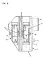
- FIG. 5is an enlarged detail view of a portion of the adapter block of FIG. 4 ;
- FIG. 6is a front perspective view of one telecommunications panel embodiment having a first mounting configuration to which the adapter block of FIG. 1 mounts, the shown adapter blocks being mounted from the front of the panel;
- FIG. 7is a rear perspective view of the telecommunications panel of FIG. 6 ;
- FIG. 8is an enlarged detail view of a portion of the telecommunications panel and one adapter block of FIG. 7 ;
- FIG. 9is a front perspective view of the telecommunications panel having the first mounting configuration of FIG. 6 , to which the adapter block of FIG. 1 mounts, the shown adapter blocks being mounted from the rear of the panel;
- FIG. 10is a rear perspective view of the telecommunications panel of FIG. 9 ;
- FIG. 11is a front perspective view of another telecommunications panel embodiment having a second mounting configuration to which the adapter block of FIG. 1 mounts;
- FIG. 12is a front perspective view of another embodiment of a multi-port adapter block, in accordance with the principles disclosed.
- FIG. 13is an exploded, front perspective view of the adapter block of FIG. 12 , shown with dust caps;
- FIG. 14is a front elevation view of the adapter block of FIG. 12 ;
- FIG. 15is a top cross-sectional view of the adapter block of FIG. 14 , taken along line 15 - 15 ;
- FIG. 16is an enlarged detail view of a portion of the adapter block of FIG. 15 ;
- FIG. 1illustrates one embodiment of a multi-port adapter block 10 in accordance with the principles disclosed.
- the adapter block 10is designed for use in the telecommunications industry.
- the adapter blockis arranged to provide interconnection between two connectorized fiber optic cables 12 (schematically represented).
- What is meant by connectorized cableis a cable having a connector 14 at an end of the cable.
- the present adapter block 10is designed for use in multiple applications having different mounting or access configurations.
- the adapter block 10can be used in applications requiring a sliding mount or sliding access, and applications requiring a front mount or front access, and applications requiring a rear mount or rear access.
- the adapter block 10 of the present disclosureincludes a one-piece housing 16 having a front 18 and a rear 20 .
- the housing 16defines a plurality of ports or openings 22 aligned in an array.
- a plurality of ports or openingsis defined as more than two ports or openings.
- the openings 22define locations at which connectorized cables are terminated.
- Each of the openings 22defines a longitudinal axis X-X (see also FIG. 4 ).
- the longitudinal axes X-X of the openingsare generally parallel to one another.
- the openings 22extend from the front 18 of the housing to the rear 20 .
- the housingfurther includes a first side 24 , a second side 26 opposite the first side, a first end 28 , and a second end 30 opposite the first end.
- Each of the first and second sides 24 , 26 and the first and second ends 28 , 30extends from the front 18 of the housing 16 to the rear 20 .
- a fiber optic sleeve assembly 32is mounted within each opening 22 of the housing 16 .
- the sleeve assembly 32includes a sleeve holder 34 and an alignment sleeve 36 .
- the sleeve holder 34holds the alignment sleeve 36 .
- the sleeve assembly 32is inserted into the opening 22 of the housing 16 from the front 18 .
- the sleeve holder 34 and housing 16include a snap-fit connection 38 ( FIGS. 4 and 5 ) that secures the sleeve assembly 32 within the housing opening 22 .
- the housing 16includes inner dividing walls 98 ( FIG. 5 ) having ramped projections 100 .
- Shoulder members 102 of the sleeve holder 34contact the ramped projections 100 during insertion into the opening 22 .
- the contact between the shoulder member 102 and the projections 100flex at least one of the inner dividing walls 98 outward until the shoulder member 102 snap-fits and seats between the ramped projection 100 and a stop element 104 formed in the opening 22 .
- the sleeve assembliesare sequentially loaded into the openings 22 from the first end 28 toward the second end 30 .
- the last dividing wall 98is spaced from the second end 30 of the housing 16 (at 106 in FIGS. 3 and 4 ) to accommodate the wall's outward flexure during insertion of the last sleeve assembly 32 .
- the alignment sleeve 36aligns a fiber optic connector (e.g., 14 ) received in one opening 22 at the front 18 of the housing 16 with another fiber optic connector received in that same opening at the rear 20 of the housing.
- a fiber optic connectore.g., 14
- the alignment sleeve 36aligns a fiber optic connector (e.g., 14 ) received in one opening 22 at the front 18 of the housing 16 with another fiber optic connector received in that same opening at the rear 20 of the housing.
- the plurality of openingsincludes twelve openings 22 .
- Other embodimentcan include a lesser number of openings or a greater number of openings.
- the openings 22are each constructed and sized to receive a cable connector (e.g., 14 , FIG. 1 ).
- the openingsdefine internal adapter structure that corresponds to external mating structure of an SC-type fiber optic connector. Further details of an SC-type fiber optic connector are described in U.S. Pat. No. 5,317,663, which patent is incorporated herein by reference.
- the sleeve holder 34is similarly constructed to mate with an SC-type fiber optic connector.
- the opening and sleeve holdercan be construction to mate with other types of connectors as well.
- dust caps 50are inserted within the openings 22 to protect the interior of each opening from contaminates.
- each of the first side 24 and the second side 26 of the one-piece housing 16defines a groove 40 , 42 (see FIG. 6 for groove 42 on second side 26 ).
- the grooves 40 , 42extend from the first end 28 of the housing 16 to the second end 30 of the housing.
- the housing 16further includes a first flexible locking arm 44 located at a first end 28 of the housing and a second flexible locking arm 46 located at the second end 30 of the housing (see also FIG. 3 ).
- Each of the flexible locking arms 44 , 46is positioned adjacent to the groove 40 on the first side 24 of the housing 16 .
- a handle 48see also FIGS.
- the grooves 40 , 42 , the first and second flexible locking arms 44 , 46 , and the handle 48work in conjunction with applications requiring a sliding mount.
- Each of the flexible locking arms 44 , 46 and the handle 48is integral with the one-piece housing.
- pivoting structure 52such as a lip or shoulder, is also located at the first end 28 of the housing 16 adjacent to the handle 48 .
- a snap-in feature or flexible latch 54is located at the second end 30 of the housing opposite that of the pivoting structure 52 .
- the pivoting structure 52 and the flexible latch 54work in conjunction with applications requiring a front mount or a rear mount.
- Each of the flexible latch 54 and the pivoting structure 52is integral with the housing 16 .
- the telecommunications panel 56has a front 58 and a rear 60 .
- Mounting flanges 70are located along each side of the panel.
- the first block mounting configurationincludes closed apertures 62 formed in the panel. What is meant by a “closed” aperture is an aperture having a perimeter formed entirely within the panel material (i.e., circumscribed by panel material), as opposed to an open-sided aperture (e.g., as opposed to the open-ended slot 82 of FIG. 11 ).
- the closed aperturesare rectangular in shape.
- the adapter block 10 of FIGS. 1-4is configured to mount within the closed apertures 62 of the panel 56 .
- FIGS. 6 and 7two adapter blocks are shown mounted, two other adapter blocks are in the process of being mounted from the front 58 of the panel 56 .
- the pivoting structure 52 at the first end 28 of the housing 16is engaged with a first vertical edge 64 of the closed aperture 62 (see FIG. 8 ).
- the adapter block 10is then pivoted about a pivot axis A-A defined generally by the first edge 64 of the panel and the pivoting structure 52 of the block.
- the flexible latch 54engages a second vertical edge 66 of the closed aperture 62 .
- the flexible latch 54includes a ramped shoulder 68 ( FIG. 4 ) that deflects that latch 54 inward during insertion into the aperture 62 .
- the latch 54Upon full insertion, the latch 54 provides a snap-fit connection that secures the adapter block 10 relative to the panel 56 .
- the flexible latches 54 of the front-mounted adapter blocks 10are accessible at the outer sides of the panel 56 .
- the adapter blockscan be front mounted in a flipped orientation by engaging the pivoting structure 52 with the second vertical edge 66 of the closed aperture and pivoting the block into a seated or snap-fit position. In this flipped orientation, the flexible latches 54 would be located toward the center of the panel.
- the pivoting structure 52 and the flexible latch 54securely mount the adapter block to the front-mount panel while still providing selective access to cable terminations of the adapter block.
- a selected adapter blockcan be access and/or removed by flexing the corresponding latch 54 inward and pivoting the selected block out from the aperture about the pivot axis.
- the adapter blocks 10can also be mounted from the rear 60 of the panel 56 in applications requiring rear mount. Similar to the previous mounting method, to rear mount an adapter block, the pivoting structure 52 at the first end 28 of the housing 16 is engaged with the second vertical edge 66 of the closed aperture 62 . The adapter block 10 is then pivoted about a pivot axis defined generally by the second edge 66 of the panel and the pivoting structure 52 of the block. As the adapter block 10 is pivoted into the closed aperture 62 , the flexible latch 54 engages the first vertical edge 64 of the closed aperture 62 , and provides a snap-fit connection that secures the adapter block 10 relative to the panel 56 .
- the flexible latches 54 of the rear-mounted adapter blocks 10are accessible at the center of the panel 56 .
- the adapter blockscan be rear mounted in a flipped orientation by engaging the pivoting structure 52 with the first vertical edge 64 of the closed aperture 62 and pivoting the block into a seated or snap-fit position. In this flipped orientation, the flexible latches 54 would be located adjacent to the mounting flanges 70 .
- the pivoting structure 52 and the flexible latch 54securely mount the adapter block to the rear-mount panel, as well as to front-mount panels, while still providing selective access to cable terminations of the adapter block in each panel application.
- a telecommunications panel 76 having a second block mounting configurationis illustrated.
- the telecommunications panel 76has a front 78 and a rear 80 .
- Mounting flanges 72are located along the top and bottom of the panel.
- the second block mounting configurationincludes open-ended slots 82 formed in the panel. What is meant by an “open-ended” slot is a slot or aperture having a perimeter that is not entirely within or circumscribed by panel material.
- the adapter block 10 of FIGS. 1-4is configured to slide mount within the open-ended slots 82 of the panel 76 .
- FIG. 11two adapter blocks are shown mounted (the lower two adapter blocks), and one adapter block (the upper adapter block) is in the process of being mounted.
- opposing horizontal edges 84 , 86 of the slot 82are positioned within the grooves 40 , 42 (see FIG. 6 ) of the adapter block housing 16 .
- the adapter block 10is then slid inward into the slot 82 .
- the adapter block 10slides relative to the panel 76 along a line of travel that is perpendicular to the longitudinal axes X-X ( FIGS. 3 and 4 ) of the openings 22 of the one-piece housing 16 .
- the telecommunications panel 76includes holes 88 located adjacent to an outer edge 90 of the panel.
- a ramped surface 92 of the second flexible arm 46engages the outer edge 90 of the panel 76 causing the second flexible arm to flex in the rearward direction; the arm 46 then engages or seats within the hole 88 .
- the ramped surface 92 of the second flexible arm 46causes the arm to disengage from the hole 88 and flex outward in the rearward direction.
- a ramped surface 94 of the first flexible arm 44then contacts the panel to flex the first flexible arm 44 in the rearward direction, the arm 44 then engages or seats within the hole 88 .
- the hole 88 and the first flexible arm 44provide a snap-fit connection that secures the adapter block 10 relative to the panel 76 .
- the adapter blockWhen the first flexible arm 44 of the block 10 seats within the hole 88 , the adapter block is retained within an inward, secured position, but can be selectively released and moved to an outward, secured position. In particular, the first flexible arm 44 and be flexed outward to disengage from the hole 88 . The adapter block 10 can then be pulled outward until the second flexible arm 46 engages the hole 88 . The second flexible arm 46 prevents the adapter block 10 from inadvertently separating from the panel 76 . In this outward, secured position, cable/connector terminations can be accessed. As can be understood, the hole 88 and the second flexible arm 46 also provide a snap-fit connection that secures the adapter block relative to the panel in the outward, secured position.
- the blockis pushed inward such that the ramped surface 92 of the second flexible arm automatically flexes the arm outward by the inward sliding movement of the block.
- the second flexible arm 46can be flexed outward to disengage from the hole 88 . The adapter block 10 can then be removed from the panel 76 .
- the handle 48 of the adapter block 10is located at open end of the open-ended slot 82 .
- the handle 48can be used to slide the block in and out of the slot 82 , and to slide the block between the inward and outward secured positions.
- the illustrated handle 48includes a face surface 96 that faces outward from the panel 76 when mounted within the open-ended slot 82 . Indicia or designation labels can be attached to the face surface 96 to provide information that is visible from the side of the panel 76 .
- the grooves 40 , 42 and the flexible arms 44 , 46securely mount the adapter block 10 to the slide-mount panel, as well as to front-mount panels and rear-mount panels, while still providing selective access to cable terminations of the adapter block in each panel application.
- the present adapter blockcan include a greater or lesser number of openings 22 to accommodate a particular application.
- FIGS. 12-16a second embodiment of a multi-port adapter block 110 is illustrated.
- the second adapter block embodiment 110has the same features as previously described with respect to the first embodiment, except that the adapter block 110 has six openings 122 aligned in an array instead of twelve.
- the adapter block 110is arranged to provide interconnection between two connectorized fiber optic cables.
- the adapter block 110includes a one-piece housing 116 that defines the plurality of ports or openings 122 aligned in the array.
- Sleeve assemblies 132( FIG. 13 ) are mounted within each one of the openings 122 .
- the sleeve assemblies each 132include a sleeve holder 134 and an alignment sleeve 136 .
- the sleeve holder 134holds the alignment sleeve 136 and is secured within the opening 122 of the housing by a snap-fit connection 138 ( FIGS. 15 and 16 ).
- the openings 122are each constructed and sized to receive a cable connector (e.g., 14 , FIG. 1 ), such as an SC-type fiber optic connector.
- a cable connectore.g., 14 , FIG. 1
- dust caps 150are inserted within the openings 122 to protect the interior of each opening from contaminates.
- the adapter block 110further includes a handle 148 , first and second flexible locking arms 144 , 146 , and grooves (e.g., 140 ) formed in the housing 116 .
- the grooves (e.g., 140 ), the first and second flexible locking arms 144 , 146 , and the handle 148work in conjunction with applications requiring a sliding mount, such as a panel having an open-ended slot sized to correspond to the length of the adapter block 110 with six openings 122 .
- the adapter block 110includes pivoting structure 152 ( FIG. 13 ) and a flexible latch 154 ( FIG. 15 ).
- the pivoting structure 152 and the flexible latch 154work in conjunction with applications requiring a front mount or a rear mount, such as a panel having a closed aperture sized to correspond to the length of the adapter block 110 .
Landscapes
- Physics & Mathematics (AREA)
- General Physics & Mathematics (AREA)
- Optics & Photonics (AREA)
- Light Guides In General And Applications Therefor (AREA)
- Mechanical Coupling Of Light Guides (AREA)
Abstract
Description
Claims (13)
Priority Applications (2)
| Application Number | Priority Date | Filing Date | Title |
|---|---|---|---|
| US13/622,082US8929707B2 (en) | 2008-03-04 | 2012-09-18 | Multi-port adapter block |
| US14/583,979US9291778B2 (en) | 2008-03-04 | 2014-12-29 | Multi-port adapter block |
Applications Claiming Priority (3)
| Application Number | Priority Date | Filing Date | Title |
|---|---|---|---|
| US6800808P | 2008-03-04 | 2008-03-04 | |
| US12/380,976US8270796B2 (en) | 2008-03-04 | 2009-03-04 | Multi-port adapter block |
| US13/622,082US8929707B2 (en) | 2008-03-04 | 2012-09-18 | Multi-port adapter block |
Related Parent Applications (1)
| Application Number | Title | Priority Date | Filing Date |
|---|---|---|---|
| US12/380,976ContinuationUS8270796B2 (en) | 2008-03-04 | 2009-03-04 | Multi-port adapter block |
Related Child Applications (1)
| Application Number | Title | Priority Date | Filing Date |
|---|---|---|---|
| US14/583,979DivisionUS9291778B2 (en) | 2008-03-04 | 2014-12-29 | Multi-port adapter block |
Publications (2)
| Publication Number | Publication Date |
|---|---|
| US20130071084A1 US20130071084A1 (en) | 2013-03-21 |
| US8929707B2true US8929707B2 (en) | 2015-01-06 |
Family
ID=41063122
Family Applications (3)
| Application Number | Title | Priority Date | Filing Date |
|---|---|---|---|
| US12/380,976Expired - Fee RelatedUS8270796B2 (en) | 2008-03-04 | 2009-03-04 | Multi-port adapter block |
| US13/622,082Expired - Fee RelatedUS8929707B2 (en) | 2008-03-04 | 2012-09-18 | Multi-port adapter block |
| US14/583,979Expired - Fee RelatedUS9291778B2 (en) | 2008-03-04 | 2014-12-29 | Multi-port adapter block |
Family Applications Before (1)
| Application Number | Title | Priority Date | Filing Date |
|---|---|---|---|
| US12/380,976Expired - Fee RelatedUS8270796B2 (en) | 2008-03-04 | 2009-03-04 | Multi-port adapter block |
Family Applications After (1)
| Application Number | Title | Priority Date | Filing Date |
|---|---|---|---|
| US14/583,979Expired - Fee RelatedUS9291778B2 (en) | 2008-03-04 | 2014-12-29 | Multi-port adapter block |
Country Status (1)
| Country | Link |
|---|---|
| US (3) | US8270796B2 (en) |
Families Citing this family (101)
| Publication number | Priority date | Publication date | Assignee | Title |
|---|---|---|---|---|
| US8270796B2 (en) | 2008-03-04 | 2012-09-18 | Adc Telecommunications, Inc. | Multi-port adapter block |
| US7903922B2 (en)* | 2008-08-07 | 2011-03-08 | Fujikura Ltd. | Optical connector holder and optical termination cabinet, and method of optical fiber wiring in optical termination cabinet |
| US8897637B2 (en) | 2009-04-22 | 2014-11-25 | Adc Gmbh | Method and arrangement for identifying at least one object |
| WO2011047281A1 (en) | 2009-10-16 | 2011-04-21 | Adc Telecommunications, Inc. | Managed connectivity in electrical systems and methods thereof |
| WO2011047288A1 (en) | 2009-10-16 | 2011-04-21 | Adc Telecommunications, Inc. | Managed connectivity in fiber optic systems and methods thereof |
| JP2013508918A (en) | 2009-10-19 | 2013-03-07 | エーディーシー テレコミュニケーションズ,インコーポレイティド | Managed electrical connection system |
| WO2011100613A1 (en) | 2010-02-12 | 2011-08-18 | Adc Telecommunications, Inc. | Communications bladed system |
| WO2011100634A2 (en) | 2010-02-12 | 2011-08-18 | Adc Telecommunications, Inc. | Managed fiber connectivity systems |
| US8696369B2 (en) | 2010-09-09 | 2014-04-15 | Adc Telecommunications, Inc. | Electrical plug with main contacts and retractable secondary contacts |
| WO2012054348A1 (en) | 2010-10-22 | 2012-04-26 | Adc Telecommunications, Inc. | Single-piece plug nose |
| US8670644B2 (en)* | 2010-11-23 | 2014-03-11 | Commscope, Inc. Of North Carolina | Manifold for managing fiber optic cable and structures and systems therefor |
| US8715012B2 (en) | 2011-04-15 | 2014-05-06 | Adc Telecommunications, Inc. | Managed electrical connectivity systems |
| WO2012149020A2 (en) | 2011-04-25 | 2012-11-01 | Adc Telecommunications, Inc. | Rack and chassis for fiber optic sliding adapter modules |
| US9064022B2 (en) | 2011-05-17 | 2015-06-23 | Adc Telecommunications, Inc. | Component identification and tracking system for telecommunication networks |
| US9188747B2 (en) | 2011-05-23 | 2015-11-17 | Senko Advanced Components, Inc. | True one piece housing fiber optic adapter |
| US20140161397A1 (en)* | 2011-07-20 | 2014-06-12 | Panduit Corp. | Fiber optic plug pack assembly |
| US9075203B2 (en) | 2012-01-17 | 2015-07-07 | Adc Telecommunications, Inc. | Fiber optic adapter block |
| US9093796B2 (en) | 2012-07-06 | 2015-07-28 | Adc Telecommunications, Inc. | Managed electrical connectivity systems |
| WO2014022781A1 (en) | 2012-08-03 | 2014-02-06 | Joseph Christopher Coffey | Managed fiber connectivity systems |
| US9203198B2 (en) | 2012-09-28 | 2015-12-01 | Commscope Technologies Llc | Low profile faceplate having managed connectivity |
| JP6027859B2 (en)* | 2012-11-16 | 2016-11-16 | 矢崎総業株式会社 | Housing connection structure |
| US9423570B2 (en)* | 2013-02-05 | 2016-08-23 | Commscope Technologies Llc | Optical assemblies with managed connectivity |
| US9285552B2 (en) | 2013-02-05 | 2016-03-15 | Commscope Technologies Llc | Optical assemblies with managed connectivity |
| US9379501B2 (en) | 2013-02-05 | 2016-06-28 | Commscope Technologies Llc | Optical assemblies with managed connectivity |
| US9268103B2 (en)* | 2013-05-10 | 2016-02-23 | Senko Advanced Components, Inc. | Interlockable fiber optic connector adaptors |
| US9360649B2 (en) | 2013-05-22 | 2016-06-07 | Senko Advanced Components, Inc. | Cable guide for fiber optic cables |
| AU2014312426A1 (en)* | 2013-08-30 | 2016-04-21 | Corning Optical Communications LLC | Gang fiber adaptor with integral mounting features |
| US9618703B2 (en) | 2013-10-03 | 2017-04-11 | Senko Advanced Components, Inc. | Connector housing for securing an optical cable and methods of use and manufacture thereof |
| US9477049B2 (en) | 2013-12-20 | 2016-10-25 | Senko Advanced Components, Inc. | Lockable connectors and connection assemblies |
| US9535230B2 (en) | 2014-01-31 | 2017-01-03 | Senko Advanced Components, Inc. | Integrated fiber optic cable fan-out connector |
| US9500814B2 (en) | 2014-03-26 | 2016-11-22 | Commscope Technologies Llc | Optical adapter module with managed connectivity |
| EP3132298B1 (en)* | 2014-04-14 | 2021-08-11 | CommScope Connectivity Belgium BVBA | Fiber optic enclosure with cable management drawer |
| US9297964B2 (en) | 2014-04-18 | 2016-03-29 | Senko Advanced Components, Inc. | Optical fiber connector assembly |
| US9274287B2 (en) | 2014-05-13 | 2016-03-01 | Senko Advanced Components, Inc. | Optical fiber connector and ferrule |
| US9618702B2 (en) | 2014-06-09 | 2017-04-11 | Senko Advanced Components, Inc. | Reduced-profile data transmission element connectors, adapters, and connection assemblies thereof |
| US9599778B2 (en) | 2014-10-22 | 2017-03-21 | Senko Advanced Components, Inc. | Latching connector with remote release |
| CA2971584C (en)* | 2014-12-19 | 2023-08-01 | 3M Innovative Properties Company | Ruggedized optical fiber connection structures and assemblies |
| US9494745B2 (en) | 2015-01-16 | 2016-11-15 | Senko Advanced Components, Inc. | Sealable communication cable connection assemblies |
| US9658409B2 (en) | 2015-03-03 | 2017-05-23 | Senko Advanced Components, Inc. | Optical fiber connector with changeable polarity |
| US9684139B2 (en) | 2015-05-29 | 2017-06-20 | Senko Advanced Components, Inc. | Optical fiber connector with changeable gender |
| EP3374812A1 (en)* | 2015-11-13 | 2018-09-19 | CommScope Connectivity Belgium BVBA | Method and arrangements for stacking adapters |
| WO2017125473A1 (en)* | 2016-01-20 | 2017-07-27 | CommScope Connectivity Belgium BVBA | Telecommunications panel assembly |
| WO2017136390A1 (en)* | 2016-02-02 | 2017-08-10 | Commscope Technologies Llc | Electrical connector system with alien crosstalk reduction devices |
| US9726830B1 (en) | 2016-06-28 | 2017-08-08 | Senko Advanced Components, Inc. | Connector and adapter system for two-fiber mechanical transfer type ferrule |
| WO2018057615A1 (en) | 2016-09-21 | 2018-03-29 | Commscope Technologies Llc | Adapter block assembly |
| US10078188B1 (en) | 2016-12-05 | 2018-09-18 | Senko Advanced Components, Inc. | Springless push/pull fiber optic connector |
| US10228521B2 (en) | 2016-12-05 | 2019-03-12 | Senko Advanced Components, Inc. | Narrow width adapters and connectors with modular latching arm |
| US10725248B2 (en) | 2017-01-30 | 2020-07-28 | Senko Advanced Components, Inc. | Fiber optic receptacle with integrated device therein incorporating a behind-the-wall fiber optic receptacle |
| CN110249248B (en) | 2017-01-30 | 2021-07-27 | 扇港元器件股份有限公司 | Optical connectors with reversible polarity |
| US10416394B2 (en) | 2017-01-30 | 2019-09-17 | Senko Advanced Components, Inc. | Fiber optic receptacle with integrated device therein |
| US10185100B2 (en) | 2017-01-30 | 2019-01-22 | Senko Advanced Components, Inc | Modular connector and adapter assembly using a removable anchor device |
| US10871619B2 (en)* | 2017-01-30 | 2020-12-22 | Senko Advanced Components, Inc. | Cassette assembly for a plural of fiber optic receptacles |
| US10444444B2 (en) | 2017-01-30 | 2019-10-15 | Senko Advanced Components, Inc. | Remote release tab connector assembly |
| US11333836B2 (en) | 2017-01-30 | 2022-05-17 | Senko Advanced Components, Inc. | Adapter for optical connectors |
| US10048451B1 (en)* | 2017-02-10 | 2018-08-14 | Hewlett Packard Enterprise Development Lp | Optical connectors with positions |
| US10754098B2 (en) | 2017-04-07 | 2020-08-25 | Senko Advanced Components, Inc. | Behind the wall optical connector with reduced components |
| US10989884B2 (en) | 2017-04-07 | 2021-04-27 | Senko Advanced Components, Inc. | Behind the wall optical connector with reduced components |
| US10209461B2 (en) | 2017-04-07 | 2019-02-19 | Senko Advanced Components | Behind the wall optical connector with reduced components |
| US10359583B2 (en) | 2017-04-07 | 2019-07-23 | Senko Advanced Components, Inc. | Behind the wall optical connector with reduced components |
| US10718910B2 (en) | 2017-05-03 | 2020-07-21 | Senko Advanced Components, Inc | Field terminated ruggedized fiber optic connector system |
| US10401576B2 (en) | 2017-05-10 | 2019-09-03 | Senko Advanced Components, Inc. | MPO micro-latch-lock connector |
| US10146016B1 (en) | 2017-05-10 | 2018-12-04 | Senko Advanced Components, Inc | MPO micro-latchlock connector |
| US10295759B2 (en) | 2017-05-18 | 2019-05-21 | Senko Advanced Components, Inc. | Optical connector with forward-biasing projections |
| US10359576B2 (en) | 2017-06-15 | 2019-07-23 | Senko Advanced Components, Inc. | SC low profile connector with optional boot |
| US10281669B2 (en) | 2017-07-14 | 2019-05-07 | Senko Advance Components, Inc. | Ultra-small form factor optical connectors |
| US12001064B2 (en) | 2017-07-14 | 2024-06-04 | Senko Advanced Components, Inc. | Small form factor fiber optic connector with multi-purpose boot |
| US11822133B2 (en) | 2017-07-14 | 2023-11-21 | Senko Advanced Components, Inc. | Ultra-small form factor optical connector and adapter |
| US10718911B2 (en) | 2017-08-24 | 2020-07-21 | Senko Advanced Components, Inc. | Ultra-small form factor optical connectors using a push-pull boot receptacle release |
| US10641972B2 (en) | 2017-08-17 | 2020-05-05 | Senko Advanced Components, Inc | Anti-jam alignment sleeve holder or connector housing for a ferrule assembly |
| US11385429B2 (en)* | 2017-10-18 | 2022-07-12 | Commscope Technologies Llc | Fiber optic connection cassette |
| US10444442B2 (en) | 2017-11-03 | 2019-10-15 | Senko Advanced Components, Inc. | MPO optical fiber connector |
| US11002923B2 (en) | 2017-11-21 | 2021-05-11 | Senko Advanced Components, Inc. | Fiber optic connector with cable boot release having a two-piece clip assembly |
| US11016250B2 (en)* | 2017-12-19 | 2021-05-25 | Us Conec, Ltd. | Mini duplex connector with push-pull polarity mechanism, carrier, and rail-receiving crimp body |
| EP3540867B1 (en)* | 2018-03-16 | 2025-01-08 | Connecteurs Electriques Deutsch | Connector housing and adapter |
| WO2019183070A2 (en) | 2018-03-19 | 2019-09-26 | Senko Advanced Components, Inc. | Removal tool for removing a plural of micro optical connectors from an adapter interface |
| EP3776038B1 (en) | 2018-03-28 | 2024-07-03 | Senko Advanced Components Inc. | Small form factor fiber optic connector with multi-purpose boot |
| US11041993B2 (en) | 2018-04-19 | 2021-06-22 | Senko Advanced Components, Inc. | Fiber optic adapter with removable insert for polarity change and removal tool for the same |
| US10921528B2 (en) | 2018-06-07 | 2021-02-16 | Senko Advanced Components, Inc. | Dual spring multi-fiber optic connector |
| CN112088327A (en) | 2018-07-15 | 2020-12-15 | 扇港元器件股份有限公司 | Subminiature Optical Connectors and Adapters |
| US10444441B1 (en) | 2018-08-10 | 2019-10-15 | Senko Advanced Components, Inc. | Pivotable housing for a fiber optic connector |
| US11073664B2 (en) | 2018-08-13 | 2021-07-27 | Senko Advanced Components, Inc. | Cable boot assembly for releasing fiber optic connector from a receptacle |
| WO2020055440A1 (en) | 2018-09-12 | 2020-03-19 | Senko Advanced Componetns, Inc. | Lc type connector with clip-on push/pull tab for releasing connector from a receptacle using a cable boot |
| US10921531B2 (en) | 2018-09-12 | 2021-02-16 | Senko Advanced Components, Inc. | LC type connector with push/pull assembly for releasing connector from a receptacle using a cable boot |
| US10921530B2 (en) | 2018-09-12 | 2021-02-16 | Senko Advanced Components, Inc. | LC type connector with push/pull assembly for releasing connector from a receptacle using a cable boot |
| US11806831B2 (en) | 2018-11-21 | 2023-11-07 | Senko Advanced Components, Inc. | Fixture and method for polishing fiber optic connector ferrules |
| US11175464B2 (en) | 2018-11-25 | 2021-11-16 | Senko Advanced Components, Inc. | Open ended spring body for use in an optical fiber connector |
| WO2020133937A1 (en)* | 2018-12-25 | 2020-07-02 | 深圳市飞博康光通讯技术有限公司 | Adapter |
| MX2020001074A (en)* | 2019-02-01 | 2021-03-25 | Ortronics Inc | Packaging assemblies for optical fiber applications. |
| US10788626B1 (en)* | 2019-03-22 | 2020-09-29 | Hewlett Packard Enterprise Development Lp | Reconfigurable optical ferrule carrier mating system |
| US11579379B2 (en) | 2019-03-28 | 2023-02-14 | Senko Advanced Components, Inc. | Fiber optic adapter assembly |
| US12038613B2 (en) | 2019-03-28 | 2024-07-16 | Senko Advanced Components, Inc. | Behind-the-wall optical connector and assembly of the same |
| US11340406B2 (en) | 2019-04-19 | 2022-05-24 | Senko Advanced Components, Inc. | Small form factor fiber optic connector with resilient latching mechanism for securing within a hook-less receptacle |
| WO2020252355A1 (en) | 2019-06-13 | 2020-12-17 | Senko Advanced Components, Inc | Lever actuated latch arm for releasing a fiber optic connector from a receptacle port and method of use |
| CN114600018B (en) | 2019-07-23 | 2024-04-09 | 扇港元器件有限公司 | Ultra-small receptacle for receiving a fiber optic connector opposite a ferrule assembly |
| US11353664B1 (en) | 2019-08-21 | 2022-06-07 | Senko Advanced Components, Inc. | Fiber optic connector |
| CN112652913A (en)* | 2019-10-10 | 2021-04-13 | 康普技术有限责任公司 | Modular telecommunications panel system and telecommunications module |
| CN112652897A (en) | 2019-10-10 | 2021-04-13 | 康普技术有限责任公司 | Modular telecommunications panel and modular telecommunications system |
| WO2021097304A1 (en) | 2019-11-13 | 2021-05-20 | Senko Advanced Components, Inc. | Fiber optic connector |
| US11276955B2 (en)* | 2020-01-06 | 2022-03-15 | Ciena Corporation | Double-blind mating pluggable-modules holder |
| CN115933091B (en)* | 2023-03-10 | 2023-06-20 | 烽火通信科技股份有限公司 | Optical fiber wiring subframe and reversing method |
| CN116577878A (en)* | 2023-05-06 | 2023-08-11 | 惠州市飞博康实业有限公司 | A multi-gang adapter suitable for high-density assembly |
Citations (28)
| Publication number | Priority date | Publication date | Assignee | Title |
|---|---|---|---|---|
| US5028801A (en)* | 1990-01-16 | 1991-07-02 | Sperry Marine Inc. | Apparatus and method for multiplexing fiber optic sensors |
| US5599206A (en)* | 1995-08-04 | 1997-02-04 | The Whitaker Corporation | Modular jack subassembly for use in a network outlet |
| US5987203A (en)* | 1997-10-09 | 1999-11-16 | Lucent Technologies Inc. | Distribution module for optical couplings |
| US6062893A (en)* | 1998-06-04 | 2000-05-16 | Molex Incorporated | Adapter frame for an electrical connector |
| US6267606B1 (en)* | 1995-01-13 | 2001-07-31 | Stratos Lightwave, Inc. | Removable transceiver module and receptacle |
| US6273752B1 (en)* | 2000-01-27 | 2001-08-14 | Hubbell Incorporated | Modular connector panel |
| US6461052B1 (en)* | 2000-03-17 | 2002-10-08 | Ortronics, Inc. | Optical fiber management module assembly |
| US20030095263A1 (en)* | 2000-02-08 | 2003-05-22 | Deepak Varshneya | Fiber optic interferometric vital sign monitor for use in magnetic resonance imaging, confined care facilities and in-hospital |
| US20040017983A1 (en)* | 1999-12-07 | 2004-01-29 | Wenzong Chen | Self-contained fiber optic connector module |
| US20050083670A1 (en)* | 2003-10-20 | 2005-04-21 | Peloza Kirk B. | Module retention latch assembly |
| US20050135768A1 (en)* | 2003-12-23 | 2005-06-23 | Rapp David E. | High density optical fiber distribution frame with modules |
| US20050281509A1 (en)* | 2004-06-18 | 2005-12-22 | 3M Innovative Properties Company | Optical connector system with EMI shielding |
| US20050281526A1 (en)* | 2004-06-18 | 2005-12-22 | Soutsada Vongseng | Multi-position fiber optic connector holder and method |
| US20060029353A1 (en)* | 2004-08-09 | 2006-02-09 | Bolster Kristofer J | Modules including multiple rows of adapters for high density optical fiber distribution frame |
| US20060228086A1 (en)* | 2005-03-31 | 2006-10-12 | Matthew Holmberg | Adapter block including connector storage |
| US7323677B1 (en)* | 2004-07-15 | 2008-01-29 | Mississippi State University | Fiber-bragg grating-loop ringdown method and apparatus |
| US7416349B2 (en) | 2005-07-27 | 2008-08-26 | Adc Telecommunications, Inc. | Fiber optic adapter module |
| US20090202214A1 (en)* | 2007-12-11 | 2009-08-13 | Adc Telecommuniactions, Inc. | Wall box adapted to be mounted at a mid-span access location of a telecommunications cable |
| US20100008635A1 (en)* | 2007-10-22 | 2010-01-14 | Adc Telecommunications, Inc. | Wavelength division multiplexing module |
| US20100054935A1 (en)* | 2008-07-01 | 2010-03-04 | Vestas Wind Systems A/S | Wind Turbine Having a Sensor System for Detecting Deformation in a Wind Turbine Rotor Blade and Corresponding Method |
| US20100081303A1 (en)* | 2008-10-01 | 2010-04-01 | Roth Richard F | High density pluggable electrical and optical connector |
| US20100129028A1 (en)* | 2008-11-21 | 2010-05-27 | Ponharith Nhep | Fiber optic telecommunications module |
| US20100158464A1 (en)* | 2006-02-13 | 2010-06-24 | Adc Telecommunications, Inc. | Fiber optic splitter module |
| US20110019964A1 (en)* | 2009-01-15 | 2011-01-27 | Ponharith Nhep | Fiber optic module and chassis |
| US20110092100A1 (en)* | 2009-10-16 | 2011-04-21 | Adc Telecommunications, Inc. | Managed connectivity in electrical systems and methods thereof |
| US20110116748A1 (en)* | 2009-10-16 | 2011-05-19 | Adc Telecommunications, Inc. | Managed connectivity in fiber optic systems and methods thereof |
| US20110115494A1 (en)* | 2009-10-19 | 2011-05-19 | Adc Telecommunications | Managed electrical connectivity systems |
| US8270796B2 (en) | 2008-03-04 | 2012-09-18 | Adc Telecommunications, Inc. | Multi-port adapter block |
Family Cites Families (5)
| Publication number | Priority date | Publication date | Assignee | Title |
|---|---|---|---|---|
| US5317663A (en) | 1993-05-20 | 1994-05-31 | Adc Telecommunications, Inc. | One-piece SC adapter |
| TW232757B (en) | 1994-01-21 | 1994-10-21 | Adc Telecommunications Inc | High-density fiber distribution frame |
| US20050135753A1 (en) | 2002-03-14 | 2005-06-23 | Daniel Eigenmann | Fibre-optic plug-in connector system |
| DE10219935A1 (en) | 2002-05-03 | 2003-11-27 | Krone Gmbh | Device for an optical fiber connection |
| US6932514B2 (en) | 2003-01-21 | 2005-08-23 | Furukawa Electric North America, Inc. | High density modular backplane connector for fiber optics |
- 2009
- 2009-03-04USUS12/380,976patent/US8270796B2/ennot_activeExpired - Fee Related
- 2012
- 2012-09-18USUS13/622,082patent/US8929707B2/ennot_activeExpired - Fee Related
- 2014
- 2014-12-29USUS14/583,979patent/US9291778B2/ennot_activeExpired - Fee Related
Patent Citations (43)
| Publication number | Priority date | Publication date | Assignee | Title |
|---|---|---|---|---|
| US5028801A (en)* | 1990-01-16 | 1991-07-02 | Sperry Marine Inc. | Apparatus and method for multiplexing fiber optic sensors |
| US6267606B1 (en)* | 1995-01-13 | 2001-07-31 | Stratos Lightwave, Inc. | Removable transceiver module and receptacle |
| US5599206A (en)* | 1995-08-04 | 1997-02-04 | The Whitaker Corporation | Modular jack subassembly for use in a network outlet |
| US5987203A (en)* | 1997-10-09 | 1999-11-16 | Lucent Technologies Inc. | Distribution module for optical couplings |
| US6062893A (en)* | 1998-06-04 | 2000-05-16 | Molex Incorporated | Adapter frame for an electrical connector |
| US7422376B2 (en)* | 1999-12-07 | 2008-09-09 | Molex Incorporated | Self-contained fiber optic connector module |
| US20040017983A1 (en)* | 1999-12-07 | 2004-01-29 | Wenzong Chen | Self-contained fiber optic connector module |
| US6273752B1 (en)* | 2000-01-27 | 2001-08-14 | Hubbell Incorporated | Modular connector panel |
| US20030095263A1 (en)* | 2000-02-08 | 2003-05-22 | Deepak Varshneya | Fiber optic interferometric vital sign monitor for use in magnetic resonance imaging, confined care facilities and in-hospital |
| US6461052B1 (en)* | 2000-03-17 | 2002-10-08 | Ortronics, Inc. | Optical fiber management module assembly |
| US20050083670A1 (en)* | 2003-10-20 | 2005-04-21 | Peloza Kirk B. | Module retention latch assembly |
| US20050135768A1 (en)* | 2003-12-23 | 2005-06-23 | Rapp David E. | High density optical fiber distribution frame with modules |
| US20050232566A1 (en)* | 2003-12-23 | 2005-10-20 | Adc Telecommunications, Inc. | High density optical fiber distribution frame with modules |
| US7218827B2 (en) | 2004-06-18 | 2007-05-15 | Adc Telecommunications, Inc. | Multi-position fiber optic connector holder and method |
| US7519259B2 (en) | 2004-06-18 | 2009-04-14 | Adc Telecommunications, Inc. | Increasing capacity of a telecommunications cabinet |
| US7809234B2 (en)* | 2004-06-18 | 2010-10-05 | Adc Telecommunications, Inc. | Telecommunications cabinet with connector storage |
| US7809233B2 (en) | 2004-06-18 | 2010-10-05 | Adc Telecommunications, Inc. | Telecommunications cabinet with connector storage |
| US7277620B2 (en) | 2004-06-18 | 2007-10-02 | Adc Telecommunications, Inc. | Fiber optic splitter |
| US7826706B2 (en) | 2004-06-18 | 2010-11-02 | Adc Telecommunications, Inc. | Telecommunications connection cabinet |
| US20110019965A1 (en)* | 2004-06-18 | 2011-01-27 | Adc Telecommunications, Inc. | Telecommunications cabinet with connector storage |
| US20050281509A1 (en)* | 2004-06-18 | 2005-12-22 | 3M Innovative Properties Company | Optical connector system with EMI shielding |
| US7515805B2 (en) | 2004-06-18 | 2009-04-07 | Adc Telecommunications, Inc. | Fiber optic splitter |
| US20050281526A1 (en)* | 2004-06-18 | 2005-12-22 | Soutsada Vongseng | Multi-position fiber optic connector holder and method |
| US20090190896A1 (en)* | 2004-06-18 | 2009-07-30 | Adc Telecommunications, Inc. | Telecommunications cabinet with connector storage |
| US7323677B1 (en)* | 2004-07-15 | 2008-01-29 | Mississippi State University | Fiber-bragg grating-loop ringdown method and apparatus |
| US20060029353A1 (en)* | 2004-08-09 | 2006-02-09 | Bolster Kristofer J | Modules including multiple rows of adapters for high density optical fiber distribution frame |
| US20100322577A1 (en)* | 2004-08-09 | 2010-12-23 | Adc Telecommunications, Inc. | Modules including multiple rows of adapters for high density optical fiber distribution frame |
| US20100266237A1 (en)* | 2005-03-31 | 2010-10-21 | Adc Telecommunications, Inc. | Adapter block including connector storage |
| US20060228086A1 (en)* | 2005-03-31 | 2006-10-12 | Matthew Holmberg | Adapter block including connector storage |
| US7416349B2 (en) | 2005-07-27 | 2008-08-26 | Adc Telecommunications, Inc. | Fiber optic adapter module |
| US7853112B2 (en)* | 2006-02-13 | 2010-12-14 | Adc Telecommunications, Inc. | Fiber optic splitter module |
| US20100158464A1 (en)* | 2006-02-13 | 2010-06-24 | Adc Telecommunications, Inc. | Fiber optic splitter module |
| US20110222830A1 (en)* | 2007-10-22 | 2011-09-15 | Adc Telecommunications, Inc. | Wavelength division multiplexing module |
| US20100008635A1 (en)* | 2007-10-22 | 2010-01-14 | Adc Telecommunications, Inc. | Wavelength division multiplexing module |
| US20090202214A1 (en)* | 2007-12-11 | 2009-08-13 | Adc Telecommuniactions, Inc. | Wall box adapted to be mounted at a mid-span access location of a telecommunications cable |
| US8270796B2 (en) | 2008-03-04 | 2012-09-18 | Adc Telecommunications, Inc. | Multi-port adapter block |
| US20100054935A1 (en)* | 2008-07-01 | 2010-03-04 | Vestas Wind Systems A/S | Wind Turbine Having a Sensor System for Detecting Deformation in a Wind Turbine Rotor Blade and Corresponding Method |
| US20100081303A1 (en)* | 2008-10-01 | 2010-04-01 | Roth Richard F | High density pluggable electrical and optical connector |
| US20100129028A1 (en)* | 2008-11-21 | 2010-05-27 | Ponharith Nhep | Fiber optic telecommunications module |
| US20110019964A1 (en)* | 2009-01-15 | 2011-01-27 | Ponharith Nhep | Fiber optic module and chassis |
| US20110116748A1 (en)* | 2009-10-16 | 2011-05-19 | Adc Telecommunications, Inc. | Managed connectivity in fiber optic systems and methods thereof |
| US20110092100A1 (en)* | 2009-10-16 | 2011-04-21 | Adc Telecommunications, Inc. | Managed connectivity in electrical systems and methods thereof |
| US20110115494A1 (en)* | 2009-10-19 | 2011-05-19 | Adc Telecommunications | Managed electrical connectivity systems |
Also Published As
| Publication number | Publication date |
|---|---|
| US20130071084A1 (en) | 2013-03-21 |
| US20150301289A1 (en) | 2015-10-22 |
| US9291778B2 (en) | 2016-03-22 |
| US8270796B2 (en) | 2012-09-18 |
| US20090232455A1 (en) | 2009-09-17 |
Similar Documents
| Publication | Publication Date | Title |
|---|---|---|
| US9291778B2 (en) | Multi-port adapter block | |
| US20250180843A1 (en) | Bladed chassis systems | |
| AU2007215468B2 (en) | Fiber optic splitter module | |
| US5969294A (en) | Fiber optic connector cabinet with rotatably mounted adapter panels | |
| US20200012064A1 (en) | Fiber optic module and system including rear connectors | |
| US7983521B2 (en) | Fiber optic termination system with retention mechanism | |
| EP2333597B1 (en) | Fiber optic module assembly and associated methods | |
| US20180372978A1 (en) | Bladed chassis systems and removable cassettes | |
| US20110129186A1 (en) | Fiber Optic Module Assembly and Associated Methods | |
| US8958679B2 (en) | Fibre-optic telecommunications module | |
| US11971598B2 (en) | Tray arrangements for cassettes | |
| CA2716107A1 (en) | Adapter plate with angled openings and method of manufacture | |
| US11686912B1 (en) | Optical fiber assemblies for accommodating mini duplex connectors | |
| US20240159983A1 (en) | Communications panel systems | |
| AU2012265621B2 (en) | Fiber optic splitter module |
Legal Events
| Date | Code | Title | Description |
|---|---|---|---|
| AS | Assignment | Owner name:TYCO ELECTRONICS SERVICES GMBH, SWITZERLAND Free format text:ASSIGNMENT OF ASSIGNORS INTEREST;ASSIGNORS:ADC TELECOMMUNICATIONS, INC.;TE CONNECTIVITY SOLUTIONS GMBH;REEL/FRAME:036908/0443 Effective date:20150825 | |
| AS | Assignment | Owner name:COMMSCOPE EMEA LIMITED, IRELAND Free format text:ASSIGNMENT OF ASSIGNORS INTEREST;ASSIGNOR:TYCO ELECTRONICS SERVICES GMBH;REEL/FRAME:036956/0001 Effective date:20150828 | |
| AS | Assignment | Owner name:COMMSCOPE TECHNOLOGIES LLC, NORTH CAROLINA Free format text:ASSIGNMENT OF ASSIGNORS INTEREST;ASSIGNOR:COMMSCOPE EMEA LIMITED;REEL/FRAME:037012/0001 Effective date:20150828 | |
| AS | Assignment | Owner name:JPMORGAN CHASE BANK, N.A., AS COLLATERAL AGENT, ILLINOIS Free format text:PATENT SECURITY AGREEMENT (TERM);ASSIGNOR:COMMSCOPE TECHNOLOGIES LLC;REEL/FRAME:037513/0709 Effective date:20151220 Owner name:JPMORGAN CHASE BANK, N.A., AS COLLATERAL AGENT, ILLINOIS Free format text:PATENT SECURITY AGREEMENT (ABL);ASSIGNOR:COMMSCOPE TECHNOLOGIES LLC;REEL/FRAME:037514/0196 Effective date:20151220 Owner name:JPMORGAN CHASE BANK, N.A., AS COLLATERAL AGENT, IL Free format text:PATENT SECURITY AGREEMENT (TERM);ASSIGNOR:COMMSCOPE TECHNOLOGIES LLC;REEL/FRAME:037513/0709 Effective date:20151220 Owner name:JPMORGAN CHASE BANK, N.A., AS COLLATERAL AGENT, IL Free format text:PATENT SECURITY AGREEMENT (ABL);ASSIGNOR:COMMSCOPE TECHNOLOGIES LLC;REEL/FRAME:037514/0196 Effective date:20151220 | |
| FEPP | Fee payment procedure | Free format text:MAINTENANCE FEE REMINDER MAILED (ORIGINAL EVENT CODE: REM.); ENTITY STATUS OF PATENT OWNER: LARGE ENTITY | |
| LAPS | Lapse for failure to pay maintenance fees | Free format text:PATENT EXPIRED FOR FAILURE TO PAY MAINTENANCE FEES (ORIGINAL EVENT CODE: EXP.); ENTITY STATUS OF PATENT OWNER: LARGE ENTITY | |
| STCH | Information on status: patent discontinuation | Free format text:PATENT EXPIRED DUE TO NONPAYMENT OF MAINTENANCE FEES UNDER 37 CFR 1.362 | |
| FP | Lapsed due to failure to pay maintenance fee | Effective date:20190106 | |
| AS | Assignment | Owner name:REDWOOD SYSTEMS, INC., NORTH CAROLINA Free format text:RELEASE BY SECURED PARTY;ASSIGNOR:JPMORGAN CHASE BANK, N.A.;REEL/FRAME:048840/0001 Effective date:20190404 Owner name:COMMSCOPE, INC. OF NORTH CAROLINA, NORTH CAROLINA Free format text:RELEASE BY SECURED PARTY;ASSIGNOR:JPMORGAN CHASE BANK, N.A.;REEL/FRAME:048840/0001 Effective date:20190404 Owner name:ANDREW LLC, NORTH CAROLINA Free format text:RELEASE BY SECURED PARTY;ASSIGNOR:JPMORGAN CHASE BANK, N.A.;REEL/FRAME:048840/0001 Effective date:20190404 Owner name:COMMSCOPE TECHNOLOGIES LLC, NORTH CAROLINA Free format text:RELEASE BY SECURED PARTY;ASSIGNOR:JPMORGAN CHASE BANK, N.A.;REEL/FRAME:048840/0001 Effective date:20190404 Owner name:ALLEN TELECOM LLC, ILLINOIS Free format text:RELEASE BY SECURED PARTY;ASSIGNOR:JPMORGAN CHASE BANK, N.A.;REEL/FRAME:048840/0001 Effective date:20190404 Owner name:COMMSCOPE TECHNOLOGIES LLC, NORTH CAROLINA Free format text:RELEASE BY SECURED PARTY;ASSIGNOR:JPMORGAN CHASE BANK, N.A.;REEL/FRAME:049260/0001 Effective date:20190404 Owner name:REDWOOD SYSTEMS, INC., NORTH CAROLINA Free format text:RELEASE BY SECURED PARTY;ASSIGNOR:JPMORGAN CHASE BANK, N.A.;REEL/FRAME:049260/0001 Effective date:20190404 Owner name:ANDREW LLC, NORTH CAROLINA Free format text:RELEASE BY SECURED PARTY;ASSIGNOR:JPMORGAN CHASE BANK, N.A.;REEL/FRAME:049260/0001 Effective date:20190404 Owner name:COMMSCOPE, INC. OF NORTH CAROLINA, NORTH CAROLINA Free format text:RELEASE BY SECURED PARTY;ASSIGNOR:JPMORGAN CHASE BANK, N.A.;REEL/FRAME:049260/0001 Effective date:20190404 Owner name:ALLEN TELECOM LLC, ILLINOIS Free format text:RELEASE BY SECURED PARTY;ASSIGNOR:JPMORGAN CHASE BANK, N.A.;REEL/FRAME:049260/0001 Effective date:20190404 | |
| AS | Assignment | Owner name:JPMORGAN CHASE BANK, N.A., NEW YORK Free format text:ABL SECURITY AGREEMENT;ASSIGNORS:COMMSCOPE, INC. OF NORTH CAROLINA;COMMSCOPE TECHNOLOGIES LLC;ARRIS ENTERPRISES LLC;AND OTHERS;REEL/FRAME:049892/0396 Effective date:20190404 Owner name:WILMINGTON TRUST, NATIONAL ASSOCIATION, AS COLLATE Free format text:PATENT SECURITY AGREEMENT;ASSIGNOR:COMMSCOPE TECHNOLOGIES LLC;REEL/FRAME:049892/0051 Effective date:20190404 Owner name:JPMORGAN CHASE BANK, N.A., NEW YORK Free format text:TERM LOAN SECURITY AGREEMENT;ASSIGNORS:COMMSCOPE, INC. OF NORTH CAROLINA;COMMSCOPE TECHNOLOGIES LLC;ARRIS ENTERPRISES LLC;AND OTHERS;REEL/FRAME:049905/0504 Effective date:20190404 Owner name:WILMINGTON TRUST, NATIONAL ASSOCIATION, AS COLLATERAL AGENT, CONNECTICUT Free format text:PATENT SECURITY AGREEMENT;ASSIGNOR:COMMSCOPE TECHNOLOGIES LLC;REEL/FRAME:049892/0051 Effective date:20190404 | |
| AS | Assignment | Owner name:RUCKUS WIRELESS, LLC (F/K/A RUCKUS WIRELESS, INC.), NORTH CAROLINA Free format text:RELEASE OF SECURITY INTEREST AT REEL/FRAME 049905/0504;ASSIGNOR:JPMORGAN CHASE BANK, N.A., AS COLLATERAL AGENT;REEL/FRAME:071477/0255 Effective date:20241217 Owner name:COMMSCOPE TECHNOLOGIES LLC, NORTH CAROLINA Free format text:RELEASE OF SECURITY INTEREST AT REEL/FRAME 049905/0504;ASSIGNOR:JPMORGAN CHASE BANK, N.A., AS COLLATERAL AGENT;REEL/FRAME:071477/0255 Effective date:20241217 Owner name:COMMSCOPE, INC. OF NORTH CAROLINA, NORTH CAROLINA Free format text:RELEASE OF SECURITY INTEREST AT REEL/FRAME 049905/0504;ASSIGNOR:JPMORGAN CHASE BANK, N.A., AS COLLATERAL AGENT;REEL/FRAME:071477/0255 Effective date:20241217 Owner name:ARRIS SOLUTIONS, INC., NORTH CAROLINA Free format text:RELEASE OF SECURITY INTEREST AT REEL/FRAME 049905/0504;ASSIGNOR:JPMORGAN CHASE BANK, N.A., AS COLLATERAL AGENT;REEL/FRAME:071477/0255 Effective date:20241217 Owner name:ARRIS TECHNOLOGY, INC., NORTH CAROLINA Free format text:RELEASE OF SECURITY INTEREST AT REEL/FRAME 049905/0504;ASSIGNOR:JPMORGAN CHASE BANK, N.A., AS COLLATERAL AGENT;REEL/FRAME:071477/0255 Effective date:20241217 Owner name:ARRIS ENTERPRISES LLC (F/K/A ARRIS ENTERPRISES, INC.), NORTH CAROLINA Free format text:RELEASE OF SECURITY INTEREST AT REEL/FRAME 049905/0504;ASSIGNOR:JPMORGAN CHASE BANK, N.A., AS COLLATERAL AGENT;REEL/FRAME:071477/0255 Effective date:20241217 |