US8928465B2 - Aftermarket module arrangement and method for communicating over a vehicle bus - Google Patents
Aftermarket module arrangement and method for communicating over a vehicle busDownload PDFInfo
- Publication number
- US8928465B2 US8928465B2US13/483,728US201213483728AUS8928465B2US 8928465 B2US8928465 B2US 8928465B2US 201213483728 AUS201213483728 AUS 201213483728AUS 8928465 B2US8928465 B2US 8928465B2
- Authority
- US
- United States
- Prior art keywords
- module
- aftermarket
- vehicle
- electric power
- power line
- Prior art date
- Legal status (The legal status is an assumption and is not a legal conclusion. Google has not performed a legal analysis and makes no representation as to the accuracy of the status listed.)
- Active, expires
Links
Images


Classifications
- H—ELECTRICITY
- H04—ELECTRIC COMMUNICATION TECHNIQUE
- H04L—TRANSMISSION OF DIGITAL INFORMATION, e.g. TELEGRAPHIC COMMUNICATION
- H04L12/00—Data switching networks
- H04L12/28—Data switching networks characterised by path configuration, e.g. LAN [Local Area Networks] or WAN [Wide Area Networks]
- H04L12/40—Bus networks
- H04L12/40006—Architecture of a communication node
- H04L12/40045—Details regarding the feeding of energy to the node from the bus
- H—ELECTRICITY
- H04—ELECTRIC COMMUNICATION TECHNIQUE
- H04B—TRANSMISSION
- H04B3/00—Line transmission systems
- H04B3/54—Systems for transmission via power distribution lines
- H04B3/548—Systems for transmission via power distribution lines the power on the line being DC
- H—ELECTRICITY
- H04—ELECTRIC COMMUNICATION TECHNIQUE
- H04L—TRANSMISSION OF DIGITAL INFORMATION, e.g. TELEGRAPHIC COMMUNICATION
- H04L12/00—Data switching networks
- H04L12/28—Data switching networks characterised by path configuration, e.g. LAN [Local Area Networks] or WAN [Wide Area Networks]
- H04L12/40—Bus networks
- H04L12/40169—Flexible bus arrangements
- H—ELECTRICITY
- H04—ELECTRIC COMMUNICATION TECHNIQUE
- H04L—TRANSMISSION OF DIGITAL INFORMATION, e.g. TELEGRAPHIC COMMUNICATION
- H04L12/00—Data switching networks
- H04L12/28—Data switching networks characterised by path configuration, e.g. LAN [Local Area Networks] or WAN [Wide Area Networks]
- H04L12/40—Bus networks
- H04L2012/40208—Bus networks characterized by the use of a particular bus standard
- H04L2012/40215—Controller Area Network CAN
- H—ELECTRICITY
- H04—ELECTRIC COMMUNICATION TECHNIQUE
- H04L—TRANSMISSION OF DIGITAL INFORMATION, e.g. TELEGRAPHIC COMMUNICATION
- H04L12/00—Data switching networks
- H04L12/28—Data switching networks characterised by path configuration, e.g. LAN [Local Area Networks] or WAN [Wide Area Networks]
- H04L12/40—Bus networks
- H04L2012/40267—Bus for use in transportation systems
- H04L2012/40273—Bus for use in transportation systems the transportation system being a vehicle
Definitions
- the technical fieldgenerally relates to a vehicle, and more particularly relates to an aftermarket module arrangement for installation into a vehicle having a vehicle bus and an electric power source and a method for communicating over a vehicle bus in a vehicle having an electric power source.
- aftermarket modulesare increasingly being utilized by vehicle operators/occupants to provide a variety of services.
- aftermarket telematics unitsthat are compatible for use with communication systems that are designed to provide a vehicle operator and/or vehicle occupant with a variety of telematics services are increasingly becoming available in the marketplace.
- an aftermarket modulemay communicate over a vehicle's CAN bus (hereinafter, “vehicle bus”) with other vehicle components and/or systems.
- vehicle busvehicle's CAN bus
- ADLvehicle's assembly line datalink
- the communicative coupling between the aftermarket module and the modulemay be accomplished via wireless communications or via a wired connection running between the aftermarket module and the module. While both of these solutions are acceptable, there is room for improvement.
- an aftermarket module arrangementthat provides an alternative mode of connectivity between the aftermarket module and the module.
- an aftermarket modulethat provides the reliable communicative coupling currently available in a wired arrangement while also providing the aesthetically pleasing appearance currently available in a wireless arrangement.
- an aftermarket module arrangement for installation into a vehicle having a vehicle bus and an electric power source and a method for communicating over a vehicle bus in a vehicle having an electric power sourceare disclosed herein.
- the aftermarket module arrangementincludes, but is not limited to, a module that is configured to communicatively couple with the vehicle bus and to electrically couple with the electric power source via a first electric power line.
- the moduleis further configured to engage in power line communications over the first electric power line.
- the aftermarket module arrangementfurther includes, but is not limited to, an aftermarket module that is configured to electrically couple with the electric power source over a second electric power line and to engage in power line communications over the second electric power line.
- the aftermarket moduleis further configured to communicatively couple with the module via power line communications and to communicate over the vehicle bus through the module when the module is communicatively coupled with the vehicle bus and when the aftermarket module is communicatively coupled with the module.
- the arrangementincludes, but is not limited to, a module that is configured to communicatively couple with the vehicle bus and to electrically couple with the electric power source via a first electric power line.
- the moduleis further configured to engage in power line communications over the first electric power line.
- the arrangementfurther includes, but is not limited to, an aftermarket module that is configured to electrically couple with the electric power source over a second electric power line and to engage in power line communications over the second electric power line.
- the arrangementstill further includes, but is not limited to, a user input module that is configured to electrically couple with the electric power source over a third electric power line and to engage in power line communications over the third electric power line.
- the aftermarket moduleis further configured to communicatively couple with the module via power line communications and to communicate over the vehicle bus through the module when the module is communicatively coupled with the vehicle bus and when the aftermarket module is communicatively coupled with the module.
- the user input moduleis configured to communicate with the aftermarket module via power line communications when the user input module and the aftermarket module are each electrically coupled to the electric power source.
- a systemin a third, non-limiting example, includes, but that is not limited to, a telematics module that is coupled to a first vehicle power supply line.
- the telematics moduleincludes a module interface for communicating over the first vehicle power supply line.
- the systemfurther includes, but is not limited to, a bus interface that is coupled to a vehicle information bus and to a second vehicle power supply line for communicating with both the second vehicle power supply line and the vehicle information bus.
- the communication with the second vehicle power supply lineis responsive to the communication with the vehicle information bus.
- the first and the second vehicle power supply linesare coupled.
- the telematics modulecommunicates with the vehicle information bus through the vehicle power supply lines and the bus interface.
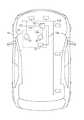
- FIG. 1is a perspective view of an interior of a vehicle fitted with a non-limiting example of an aftermarket module arrangement of the present disclosure
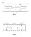
- FIG. 2is schematic view of a non-limiting example of a module configured for use with the aftermarket module arrangement of the present disclosure
- FIG. 3is schematic view of a non-limiting example of an aftermarket module configured for use with the aftermarket module arrangement of the present disclosure
- FIG. 4is schematic view of a non-limiting example of a user input module configured for use with the aftermarket module arrangement of the present disclosure
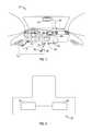
- FIG. 5is schematic view of the vehicle of FIG. 1 fitted with the non-limiting example of the aftermarket module arrangement of FIG. 1 ;
- FIG. 6is a block diagram illustrating a non-limiting example of a method of communicating over a vehicle bus using an aftermarket module arrangement.
- An aftermarket module arrangementis disclosed and described herein that is configured for installation into a vehicle having a vehicle bus and an electric power source, such as a conventional 12 Volt car battery.
- the aftermarket module arrangementis further configured to facilitate communication between an aftermarket module, such as an aftermarket telematics unit, and another component of the vehicle over the vehicle bus.
- the aftermarket module arrangementdoes not rely on wireless communications to facilitate such communication. Nor does it rely on direct wired connectivity between the individual components of the arrangement. Rather, the aftermarket module arrangement of the present disclosure relies on power line communication between the individual components of the arrangement. This provides the added benefit of flexibility to position any desired sensor at any desirable location around the vehicle. By electrically connecting the sensor to the vehicle's battery, the sensors are communicatively coupled to other devices in the vehicle.
- Power line communication systemsare known in the art and entail carrying data on a conductor that is also used for electric power transmission. In this manner, the need for wiring that is dedicated to transmitting communication signals between discreet components of the system can be eliminated. Power line communication systems operate by impressing and decoding a modulated carrier signal on the wiring system. Accordingly, each component of the aftermarket module arrangement of the present disclosure is configured to not only receive electric power from the electric power source, but also to communicate over the electric power lines that deliver such electric power from the electric power source. In this way, the number of wires required by the arrangement can be reduced, providing a more pleasing aesthetic appearance while still facilitating communication between the aftermarket module and the vehicle bus.
- Vehicle 74includes a vehicle bus (see FIG. 5 ) and an electric power source (see FIG. 5 ) and an embodiment of an aftermarket module arrangement 76 .
- Aftermarket module arrangement 76includes a module 78 , an aftermarket module 80 , and a user input module 82 .
- module 78may comprise a dongle.
- Vehicle 74includes a power outlet 84 and a power outlet 86 which provide electrical connectivity to the electric power source.
- aftermarket module 80includes a wire 88 and a plug 90 configured to engage power outlet 84 .
- plug 90engages power outlet 84
- user input module 82includes a plug 92 configured to engage with power outlet 86 .
- plug 92is engaged with power outlet 86
- user input module 82is electrically connected to the electric power source.
- aftermarket module 80 and user input module 82may be connected to the electric power supply of vehicle 74 in any suitable and/or desirable manner.
- aftermarket module 80is depicted as being an aftermarket telematics unit in the form of a rear view mirror, it should be understood that the teachings herein are compatible with any type and variety of aftermarket module.
- Vehicle 74further includes an ALDL (see FIG. 6 ) and an ALDL access port 94 which provides communicative connectivity to the vehicle bus through the ALDL.
- ALDL access port 94further provides electrical connectivity through the ALDL to the electric power source.
- module 78is configured to engage ALDL access port 94 . When module 78 engages ALDL access port 94 , module 78 is thereby communicatively connected to the vehicle bus and electrically connected to the electric power source.
- the present discussiondescribes communication with the vehicle bus via the ALDL and an access port, it should be understood that other means of communicating with the vehicle bus may also be employed.
- FIG. 2provides a schematic illustration of module 78 .
- Conventional modulesincluding, but not limited to dongles, may be configured to facilitate communication between an external component, such as an aftermarket module, and the vehicle bus.
- Some examples of conventional donglesinclude an ecoRouteTM HD, offered by Garmin under the part number 010-11380-00.
- module 78includes a processor 96 and a power line communication device 98 .
- Processor 96may be any type of computer or microprocessor that is configured to perform algorithms, to execute software applications, to execute sub-routines and/or to be loaded with and to execute any other type of computer program.
- Processor 96is configured to receive and transmit messages across the vehicle bus.
- processor 96may control an ALDL interface component to receive and transmit messages across the vehicle bus.
- Power line communication device 98may comprise any suitable device that is configured to engage in power line communication.
- power line communication device 98comprises a power line modulator/demodulator.
- Power line communication device 98is configured to impress a modulated carrier signal on the power transmission line that delivers electric power to module 78 from the electric power source for communication to other components, such as the aftermarket module, that are connected to the same electric power source.
- Power line communication device 98is further configured to interpret a modulated carrier signal delivered to module 78 on the power transmission line that delivers electric power to module 78 from the electric power source.
- Processor 96is communicatively coupled with power line communication device 98 and is configured to control power line communication device 98 to send and receive such modulated carrier signals over the power transmission line that delivers electric power to module 78 from the electric power source.
- FIG. 3provides a schematic illustration of aftermarket module 80 .
- aftermarket module 80comprises an aftermarket telematics unit.
- aftermarket modulemay comprise any suitable aftermarket module configured to engage in communication with and/or over the vehicle bus.
- Conventional aftermarket telematics unitsare known and are disclosed in a pending U.S. patent application having the Ser. No. 12/787,472 filed on May 26, 2010, and also in U.S. Publication No. 2005/0273211 published on Dec. 8, 2005, each of which is hereby incorporated herein by reference in its entirety.
- aftermarket module 80includes a processor 100 and a power line communication device 102 .
- Power line communication device 102may comprise any suitable device configured to engage in power line communication.
- power line communication device 102comprises a modulator/demodulator.
- Processor 100is communicatively coupled with power line communication device 102 and is configured to control power line communication device 102 to engage in power line communications across the power transmission lines that deliver electric power from the electric power source.
- aftermarket module 80further includes an electronic storage device 104 that enables aftermarket module 80 to store electronic data and a cellular chipset 106 that enables aftermarket module 80 to engage in extravehicular communications.
- FIG. 4provides a schematic illustration of user input module 82 .
- user input module 82may be any component suitable to receive inputs from an operator of vehicle 74 .
- user input modulemay be a keyboard, a mouse, a touch screen, a tablet and stylus, a switch, a knob, a slide, a microphone, a camera, a motion detector, or any other device that is configured to permit a human to provide inputs into an electronic system.
- user input module 82comprises a device having multiple buttons ( 108 , 110 , and 112 ) associated with various desired actions which may be undertaken by aftermarket module 80 .
- User input module 82further includes a processor 114 and a power line communication device 116 .
- Power line communication device 116may be any suitable device configured to engage in power line communications.
- power line communication device 116comprises a power line modulator/demodulator.
- Processor 114is communicatively coupled with power line communication device 116 and is configured to control power line communication device 116 to engage in power line communications.
- FIG. 5provides a schematic view of vehicle 74 equipped with aftermarket module arrangement 76 .
- Vehicle 74includes a vehicle bus 118 , an ALDL 120 communicatively coupled with vehicle bus 118 , and an electric power source 122 in the form of a conventional car battery.
- the vehicle 74further includes multiple components communicatively coupled to vehicle bus 118 .
- a wire 124electrically connects electric power source 122 and ALDL 120 .
- module 78draws electric power from electric power source 122 through ALDL 120 .
- a wire 124may connect electric power source 122 to vehicle bus 118 while in still other examples, wire 124 may directly connect electric power source 122 to module 78 .
- a wire 126electrically connects electric power source 122 to aftermarket module 80 .
- wire 126may lead to a power outlet of vehicle 74 and aftermarket module 80 may be configured to plug into that power outlet.
- a wire 128is electrically connects electric power source 122 and a user input module 82 .
- wire 128may lead to a power outlet of vehicle 74 and user input module 82 may be configured to plug into that power outlet.
- each component of aftermarket module arrangement 76is configured to engage in power line communications. Accordingly, each component of aftermarket module arrangement 76 may transmit and receive messages to and from one another over the wired connection formed by wires 124 , 126 , and 128 .
- a driver or other usermay provide an input into user input module 82 .
- User input module 82will convert the user input into a message that is transmitted via wire 128 through electric power source 122 (or, in other examples, through some other juncture) and on through wire 126 to aftermarket module 80 .
- aftermarket module 80will transmit a message via wire 126 , through electric power source 122 , and on through wire 124 and ALDL 120 to module 78 .
- Module 78is configured to receive and interpret the message sent by aftermarket module 80 , and in response, to generate a vehicle bus message and to transmit that vehicle bus message through ALDL 120 and across vehicle bus 118 to an appropriate vehicle component that is coupled with vehicle bus 118 . A response by that vehicle component may be transmitted back to aftermarket module 80 along the same route in reverse sequence.
- FIG. 6provides a block diagram of an example of a method 130 for communicating over a vehicle bus in a vehicle having an electric power source.
- a moduleis communicatively coupled to the vehicle bus.
- the moduleis configured for power line communications.
- the moduleis electrically connected to the electric power source.
- the communicative connection between the module and the vehicle busmay be electrified. In such examples, the steps performed at block 132 and 134 would collapse into a single step.
- aftermarket moduleis electrically connected to the electric power source.
- the aftermarket moduleis configured to engage in power line communications.
- the aftermarket moduleis communicatively coupled with the module via power line communications.
- the aftermarket modulecommunicates over the vehicle bus via power line communications routed through the module.
Landscapes
- Engineering & Computer Science (AREA)
- Computer Networks & Wireless Communication (AREA)
- Signal Processing (AREA)
- Power Engineering (AREA)
- Cable Transmission Systems, Equalization Of Radio And Reduction Of Echo (AREA)
- Electric Propulsion And Braking For Vehicles (AREA)
- Remote Monitoring And Control Of Power-Distribution Networks (AREA)
Abstract
Description
Claims (20)
Priority Applications (2)
| Application Number | Priority Date | Filing Date | Title |
|---|---|---|---|
| US13/483,728US8928465B2 (en) | 2012-05-30 | 2012-05-30 | Aftermarket module arrangement and method for communicating over a vehicle bus |
| CN201310208734.4ACN103457813B (en) | 2012-05-30 | 2013-05-30 | Aftermarket module arrangement and method for communicating over a vehicle bus |
Applications Claiming Priority (1)
| Application Number | Priority Date | Filing Date | Title |
|---|---|---|---|
| US13/483,728US8928465B2 (en) | 2012-05-30 | 2012-05-30 | Aftermarket module arrangement and method for communicating over a vehicle bus |
Publications (2)
| Publication Number | Publication Date |
|---|---|
| US20130321134A1 US20130321134A1 (en) | 2013-12-05 |
| US8928465B2true US8928465B2 (en) | 2015-01-06 |
Family
ID=49669514
Family Applications (1)
| Application Number | Title | Priority Date | Filing Date |
|---|---|---|---|
| US13/483,728Active2032-12-01US8928465B2 (en) | 2012-05-30 | 2012-05-30 | Aftermarket module arrangement and method for communicating over a vehicle bus |
Country Status (2)
| Country | Link |
|---|---|
| US (1) | US8928465B2 (en) |
| CN (1) | CN103457813B (en) |
Cited By (2)
| Publication number | Priority date | Publication date | Assignee | Title |
|---|---|---|---|---|
| US20120163621A1 (en)* | 2010-12-23 | 2012-06-28 | Riggs Brett D | Original equipment manufacturer ("oem") integration amplifier |
| USD947699S1 (en) | 2019-03-11 | 2022-04-05 | Dometic Sweden Ab | Controller |
Families Citing this family (1)
| Publication number | Priority date | Publication date | Assignee | Title |
|---|---|---|---|---|
| US11956026B2 (en) | 2022-05-09 | 2024-04-09 | GM Global Technology Operations LLC | System and method for power line communication (PLC) and data flow control |
Citations (23)
| Publication number | Priority date | Publication date | Assignee | Title |
|---|---|---|---|---|
| US4602127A (en)* | 1984-03-09 | 1986-07-22 | Micro Processor Systems, Inc. | Diagnostic data recorder |
| US4694408A (en)* | 1986-01-15 | 1987-09-15 | Zaleski James V | Apparatus for testing auto electronics systems |
| US4757463A (en)* | 1986-06-02 | 1988-07-12 | International Business Machines Corp. | Fault isolation for vehicle using a multifunction test probe |
| US4796206A (en)* | 1986-06-02 | 1989-01-03 | International Business Machines Corporation | Computer assisted vehicle service featuring signature analysis and artificial intelligence |
| US4831560A (en)* | 1986-01-15 | 1989-05-16 | Zaleski James V | Method for testing auto electronics systems |
| US5541840A (en)* | 1993-06-25 | 1996-07-30 | Chrysler Corporation | Hand held automotive diagnostic service tool |
| US5555498A (en)* | 1994-03-18 | 1996-09-10 | Chrysler Corporation | Circuit and method for interfacing vehicle controller and diagnostic test instrument |
| US5780782A (en)* | 1995-02-15 | 1998-07-14 | Hi-Tech Transport Electronics, Inc. | On-board scale with remote sensor processing |
| US20020110146A1 (en)* | 2001-02-08 | 2002-08-15 | Thayer Peter A. | System and method for managing wireless vehicular communications |
| US20030083079A1 (en)* | 2001-10-15 | 2003-05-01 | Clark Noel E. | Method and system for communicating telematics messages |
| US20050167172A1 (en)* | 2003-07-23 | 2005-08-04 | Fernandez Dennis S. | Telematic method and apparatus with integrated power source |
| US20060170285A1 (en)* | 2005-01-13 | 2006-08-03 | Kazuya Morimitsu | Data transmission system and data transmission method |
| US20070142977A1 (en)* | 2007-02-06 | 2007-06-21 | Alex Munoz | Mutli-function control and display apparatus and device for automobiles |
| US20070201540A1 (en)* | 2006-02-14 | 2007-08-30 | Berkman William H | Hybrid power line wireless communication network |
| US20080303343A1 (en)* | 2005-06-16 | 2008-12-11 | Mitsubishi Materials Corporation | Power Line Communications System and Power Line Communications Method |
| US20090284391A1 (en)* | 2008-05-15 | 2009-11-19 | Eric Berkobin | Apparatus for mounting a telematics user interface |
| US20100271172A1 (en)* | 2009-04-27 | 2010-10-28 | Mitsubishi Electric Corporation | Car-charging system |
| US8054200B1 (en)* | 2008-12-11 | 2011-11-08 | Neva Products, Llc | Control apparatus, method, and algorithm for turning on warning in response to strobe |
| US20120007441A1 (en)* | 2007-06-01 | 2012-01-12 | Michael Sasha John | Wireless Power Harvesting and Transmission with Heterogeneous Signals. |
| US20120089298A1 (en)* | 2010-10-07 | 2012-04-12 | General Motors Llc | Aftermarket telematics unit and method for installation verification |
| US20120172087A1 (en)* | 2011-01-04 | 2012-07-05 | Parrot | Architecture of a multimedia and hands-free phone equipment for a motor vehicle |
| US20120274456A1 (en)* | 2011-04-26 | 2012-11-01 | General Motors Llc | Systems and methods for detecting an error in the installation of an electrical component |
| US20130039511A1 (en)* | 1998-11-17 | 2013-02-14 | Brett D. Riggs | Vehicle remote control interface for controlling multiple electronic devices |
Family Cites Families (10)
| Publication number | Priority date | Publication date | Assignee | Title |
|---|---|---|---|---|
| US7612528B2 (en)* | 1999-06-21 | 2009-11-03 | Access Business Group International Llc | Vehicle interface |
| US7999408B2 (en)* | 2003-05-16 | 2011-08-16 | Continental Automotive Systems, Inc. | Power and communication architecture for a vehicle |
| CN100534273C (en)* | 2006-06-26 | 2009-08-26 | 株洲南车时代电气股份有限公司 | A vehicle control module |
| DE102007012304A1 (en)* | 2007-03-14 | 2008-09-18 | Robert Bosch Gmbh | Interface in a vehicle and method for data exchange |
| CN201368984Y (en)* | 2008-12-05 | 2009-12-23 | 中国汽车技术研究中心 | Multiple-protocol data convertor for diagnosing automobile fault |
| CN101477360A (en)* | 2008-12-18 | 2009-07-08 | 天津市天锻压力机有限公司 | Multi-module data transmission communication system |
| US8541903B2 (en)* | 2010-02-03 | 2013-09-24 | Panasonic Automotive Systems Company Of America, Division Of Panasonic Corporation Of North America | Power line communication system and method |
| JP2012038040A (en)* | 2010-08-05 | 2012-02-23 | Auto Network Gijutsu Kenkyusho:Kk | Processing system, processing unit, and power supply control method |
| CN202067117U (en)* | 2011-03-03 | 2011-12-07 | 南京交通职业技术学院 | Bus-mounted intelligent system based on PLC (programmable logic controller) |
| CN102455697B (en)* | 2011-03-25 | 2013-11-06 | 扬州亚星客车股份有限公司 | Electric bus vehicle control unit based on programmable logic controller (PLC) technology |
- 2012
- 2012-05-30USUS13/483,728patent/US8928465B2/enactiveActive
- 2013
- 2013-05-30CNCN201310208734.4Apatent/CN103457813B/enactiveActive
Patent Citations (32)
| Publication number | Priority date | Publication date | Assignee | Title |
|---|---|---|---|---|
| US4602127A (en)* | 1984-03-09 | 1986-07-22 | Micro Processor Systems, Inc. | Diagnostic data recorder |
| US4694408A (en)* | 1986-01-15 | 1987-09-15 | Zaleski James V | Apparatus for testing auto electronics systems |
| US4831560A (en)* | 1986-01-15 | 1989-05-16 | Zaleski James V | Method for testing auto electronics systems |
| US4757463A (en)* | 1986-06-02 | 1988-07-12 | International Business Machines Corp. | Fault isolation for vehicle using a multifunction test probe |
| US4796206A (en)* | 1986-06-02 | 1989-01-03 | International Business Machines Corporation | Computer assisted vehicle service featuring signature analysis and artificial intelligence |
| US5541840A (en)* | 1993-06-25 | 1996-07-30 | Chrysler Corporation | Hand held automotive diagnostic service tool |
| US6181992B1 (en)* | 1993-06-25 | 2001-01-30 | Chrysler Corporation | Automotive diagnostic service tool with hand held tool and master controller |
| US5555498A (en)* | 1994-03-18 | 1996-09-10 | Chrysler Corporation | Circuit and method for interfacing vehicle controller and diagnostic test instrument |
| US5780782A (en)* | 1995-02-15 | 1998-07-14 | Hi-Tech Transport Electronics, Inc. | On-board scale with remote sensor processing |
| US20130039511A1 (en)* | 1998-11-17 | 2013-02-14 | Brett D. Riggs | Vehicle remote control interface for controlling multiple electronic devices |
| US20020110146A1 (en)* | 2001-02-08 | 2002-08-15 | Thayer Peter A. | System and method for managing wireless vehicular communications |
| US20030083079A1 (en)* | 2001-10-15 | 2003-05-01 | Clark Noel E. | Method and system for communicating telematics messages |
| US20080269971A1 (en)* | 2003-07-23 | 2008-10-30 | Fernandez Dennis S | Telematic Method and Apparatus with Integrated Power Source |
| US7621361B1 (en)* | 2003-07-23 | 2009-11-24 | Dennis Fernandez | Telematic method and apparatus with integrated power source |
| US20050167172A1 (en)* | 2003-07-23 | 2005-08-04 | Fernandez Dennis S. | Telematic method and apparatus with integrated power source |
| US20100000810A1 (en)* | 2003-07-23 | 2010-01-07 | Fernandez Dennis S | Telematic Method and Apparatus with Integrated Power Source |
| US20070051544A1 (en)* | 2003-07-23 | 2007-03-08 | Fernandez Dennis S | Telematic method and apparatus with integrated power source |
| US20090125193A1 (en)* | 2003-07-23 | 2009-05-14 | Fernandez Dennis S | Telematic Method and Apparatus with Integrated Power Source |
| US7575080B2 (en)* | 2003-07-23 | 2009-08-18 | Fernandez Dennis S | Telematic method and apparatus with integrated power source |
| US20090312896A1 (en)* | 2003-07-23 | 2009-12-17 | Fernandez Dennis S | Telematic Method and Apparatus with Integrated Power Source |
| US20060170285A1 (en)* | 2005-01-13 | 2006-08-03 | Kazuya Morimitsu | Data transmission system and data transmission method |
| US20080303343A1 (en)* | 2005-06-16 | 2008-12-11 | Mitsubishi Materials Corporation | Power Line Communications System and Power Line Communications Method |
| US20070201540A1 (en)* | 2006-02-14 | 2007-08-30 | Berkman William H | Hybrid power line wireless communication network |
| US7737831B2 (en)* | 2007-02-06 | 2010-06-15 | Alex Munoz | Multi-function control and display apparatus and device for automobiles |
| US20070142977A1 (en)* | 2007-02-06 | 2007-06-21 | Alex Munoz | Mutli-function control and display apparatus and device for automobiles |
| US20120007441A1 (en)* | 2007-06-01 | 2012-01-12 | Michael Sasha John | Wireless Power Harvesting and Transmission with Heterogeneous Signals. |
| US20090284391A1 (en)* | 2008-05-15 | 2009-11-19 | Eric Berkobin | Apparatus for mounting a telematics user interface |
| US8054200B1 (en)* | 2008-12-11 | 2011-11-08 | Neva Products, Llc | Control apparatus, method, and algorithm for turning on warning in response to strobe |
| US20100271172A1 (en)* | 2009-04-27 | 2010-10-28 | Mitsubishi Electric Corporation | Car-charging system |
| US20120089298A1 (en)* | 2010-10-07 | 2012-04-12 | General Motors Llc | Aftermarket telematics unit and method for installation verification |
| US20120172087A1 (en)* | 2011-01-04 | 2012-07-05 | Parrot | Architecture of a multimedia and hands-free phone equipment for a motor vehicle |
| US20120274456A1 (en)* | 2011-04-26 | 2012-11-01 | General Motors Llc | Systems and methods for detecting an error in the installation of an electrical component |
Cited By (4)
| Publication number | Priority date | Publication date | Assignee | Title |
|---|---|---|---|---|
| US20120163621A1 (en)* | 2010-12-23 | 2012-06-28 | Riggs Brett D | Original equipment manufacturer ("oem") integration amplifier |
| USD947699S1 (en) | 2019-03-11 | 2022-04-05 | Dometic Sweden Ab | Controller |
| USD1013546S1 (en) | 2019-03-11 | 2024-02-06 | Dometic Sweden Ab | Controller |
| USD1064878S1 (en) | 2019-03-11 | 2025-03-04 | Dometic Sweden Ab | Controller |
Also Published As
| Publication number | Publication date |
|---|---|
| CN103457813B (en) | 2017-04-12 |
| CN103457813A (en) | 2013-12-18 |
| US20130321134A1 (en) | 2013-12-05 |
Similar Documents
| Publication | Publication Date | Title |
|---|---|---|
| US9535602B2 (en) | System and method for promoting connectivity between a mobile communication device and a vehicle touch screen | |
| KR20190076731A (en) | Method for Outputting Contents via Checking Passenger Terminal and Distraction | |
| KR102367053B1 (en) | Electronic apparatus for performing communication with an external electronic device | |
| CN110562171A (en) | Automobile electric control system and automobile | |
| CN103425494A (en) | Information interaction system of vehicle-mounted terminal and smart mobile terminal | |
| CN110278277A (en) | Systems for Implementing In-vehicle Infotainment Functions | |
| CN112532783A (en) | Vehicle machine, intelligent mobile terminal and corresponding connection control method and system | |
| CN104935986A (en) | System and method for controlling multi source and multi display | |
| US20140038527A1 (en) | Car A/V System for Wireless Communication | |
| CN110663151B (en) | Vehicle-mounted system | |
| US20140280439A1 (en) | Method and Apparatus for Seamless Application Portability Over Multiple Environments | |
| US8928465B2 (en) | Aftermarket module arrangement and method for communicating over a vehicle bus | |
| CN115139939B (en) | Method and system for connecting and controlling vehicle-mounted peripheral equipment | |
| CN106506583B (en) | Method and system for wireless data transmission of vehicle computing system | |
| US20130039027A1 (en) | Housing electronic components in automotive fuses | |
| US9623818B2 (en) | Sensor system for an electric/electronic architecture and associated electric/electronic architecture for a vehicle | |
| CN110336962B (en) | Signal processing method, adapter plate, HUD device and storage medium | |
| CN104717273B (en) | For connecting the terminal installation and method of the head unit of vehicle | |
| JP2003218904A (en) | In-vehicle communication system | |
| CA2997324C (en) | Electronic logging device | |
| CN109690645A (en) | For sensing the scheme of the ambient enviroment of motor vehicle | |
| CN210941352U (en) | Upgrading system of vehicle-mounted full liquid crystal instrument and vehicle with same | |
| CN101539775A (en) | Automobile control module system for identifying address automatically | |
| CN203605950U (en) | Vehicle-mounted information system | |
| CN103797768B (en) | Device for distributing data about a vehicle |
Legal Events
| Date | Code | Title | Description |
|---|---|---|---|
| AS | Assignment | Owner name:GENERAL MOTORS LLC, MICHIGAN Free format text:ASSIGNMENT OF ASSIGNORS INTEREST;ASSIGNORS:FRYE, MARK S.;CEPURAN, LAWRENCE D.;EVERHART, CHARLES A.;AND OTHERS;SIGNING DATES FROM 20120525 TO 20120529;REEL/FRAME:028296/0033 | |
| AS | Assignment | Owner name:WILMINGTON TRUST COMPANY, DELAWARE Free format text:SECURITY AGREEMENT;ASSIGNOR:GENERAL MOTORS LLC;REEL/FRAME:030689/0154 Effective date:20101027 | |
| FEPP | Fee payment procedure | Free format text:PAYOR NUMBER ASSIGNED (ORIGINAL EVENT CODE: ASPN); ENTITY STATUS OF PATENT OWNER: LARGE ENTITY | |
| AS | Assignment | Owner name:GENERAL MOTORS LLC, MICHIGAN Free format text:RELEASE BY SECURED PARTY;ASSIGNOR:WILMINGTON TRUST COMPANY;REEL/FRAME:034183/0436 Effective date:20141017 | |
| STCF | Information on status: patent grant | Free format text:PATENTED CASE | |
| MAFP | Maintenance fee payment | Free format text:PAYMENT OF MAINTENANCE FEE, 4TH YEAR, LARGE ENTITY (ORIGINAL EVENT CODE: M1551) Year of fee payment:4 | |
| MAFP | Maintenance fee payment | Free format text:PAYMENT OF MAINTENANCE FEE, 8TH YEAR, LARGE ENTITY (ORIGINAL EVENT CODE: M1552); ENTITY STATUS OF PATENT OWNER: LARGE ENTITY Year of fee payment:8 |