US8928425B1 - Common mode detector for a communication system - Google Patents
Common mode detector for a communication systemDownload PDFInfo
- Publication number
- US8928425B1 US8928425B1US12/604,323US60432309AUS8928425B1US 8928425 B1US8928425 B1US 8928425B1US 60432309 AUS60432309 AUS 60432309AUS 8928425 B1US8928425 B1US 8928425B1
- Authority
- US
- United States
- Prior art keywords
- common
- mode
- differential
- transceiver
- ethernet
- Prior art date
- Legal status (The legal status is an assumption and is not a legal conclusion. Google has not performed a legal analysis and makes no representation as to the accuracy of the status listed.)
- Active, expires
Links
Images


Classifications
- H—ELECTRICITY
- H04—ELECTRIC COMMUNICATION TECHNIQUE
- H04B—TRANSMISSION
- H04B3/00—Line transmission systems
- H04B3/02—Details
- H04B3/32—Reducing cross-talk, e.g. by compensating
- H—ELECTRICITY
- H01—ELECTRIC ELEMENTS
- H01F—MAGNETS; INDUCTANCES; TRANSFORMERS; SELECTION OF MATERIALS FOR THEIR MAGNETIC PROPERTIES
- H01F19/00—Fixed transformers or mutual inductances of the signal type
- H01F19/04—Transformers or mutual inductances suitable for handling frequencies considerably beyond the audio range
- H—ELECTRICITY
- H04—ELECTRIC COMMUNICATION TECHNIQUE
- H04B—TRANSMISSION
- H04B3/00—Line transmission systems
- H04B3/02—Details
- H04B3/30—Reducing interference caused by unbalanced currents in a normally balanced line
- H—ELECTRICITY
- H04—ELECTRIC COMMUNICATION TECHNIQUE
- H04L—TRANSMISSION OF DIGITAL INFORMATION, e.g. TELEGRAPHIC COMMUNICATION
- H04L25/00—Baseband systems
- H04L25/02—Details ; arrangements for supplying electrical power along data transmission lines
- H04L25/0264—Arrangements for coupling to transmission lines
- H04L25/0272—Arrangements for coupling to multiple lines, e.g. for differential transmission
- H04L25/0276—Arrangements for coupling common mode signals
- H—ELECTRICITY
- H04—ELECTRIC COMMUNICATION TECHNIQUE
- H04L—TRANSMISSION OF DIGITAL INFORMATION, e.g. TELEGRAPHIC COMMUNICATION
- H04L27/00—Modulated-carrier systems
- H04L27/26—Systems using multi-frequency codes
- H04L27/2601—Multicarrier modulation systems
- H04L27/2647—Arrangements specific to the receiver only
Definitions
- This applicationis related to:
- the present inventionrelates generally to communication systems and more specifically to a common mode circuit for a communication system.
- the datais encoded on a modulated signal which is typically transmitted differentially over a pair of wires.
- the common component of the differential signal on the two wiresdoes not carry any information and it is typically noise from electro-magnetic interference (EMI) and crosstalk.
- Examples of wireline communication systems that are susceptible to common mode noiseinclude various flavors of Digital Subscriber Line (DSL) and Ethernet over copper.
- DSLDigital Subscriber Line
- Ethernetover copper.
- the communication mediumtypically consists of multiple cascaded sections of twisted pair of wires typically terminated with transformers at both ends.
- FIG. 1shows a circuit 100 that includes a termination of a twisted pair of wires 110 into a transformer 130 .
- the transformer 130is coupled to a transceiver 140 and is primarily used for DC isolation and common mode rejection.
- FIG. 1also shows a common mode choke 120 which is sometimes included to further block the common mode signal. It also provides proper impedance termination for common mode signal which prevents reflections and standing waves.
- the common mode componentIn a perfect system, the common mode component is very well balanced and does not convert to a differential signal. However, in any practical system the transversal conversion loss (TCL) is finite which means some portion of the common mode signal shows up as differential noise at the receiver.
- TCLtransversal conversion loss
- the imbalance that would cause a finite TCLcan be anywhere in the signal path including the wireline channel, the connectors at both end of the channel, and even the components that is used to detect the differential signal. This noise may be a limiting factor in the performance of a wireline communication system. Therefore, it is important to be able to detect the common mode component for characterization purposes as well as potential improvement in the performance.
- the present inventionaddresses such a need.
- a circuit for a wireline systemincludes a twisted pair channel.
- the twisted pair channeldelivers a differential signal that includes a converter mode component.
- the circuitincludes at least one transformer coupled to the twisted pair channel and a transceiver coupled to the at least one transformer.
- the circuitfurther includes a common mode detection coupled to the transceiver for detecting a common mode component.
- the circuitdetects the common mode component. Accordingly, with common mode component detection capability, the common mode component of the differential can be analyzed for characterization purposes as well as for potential improvement in the system performance signal.
- FIG. 1shows such a termination of a twisted pair into a transformer.
- FIG. 2shows a common mode circuit in accordance with an embodiment of the present invention.
- FIG. 3shown an alternate embodiment of the common mode circuit in accordance with an embodiment of the present invention.
- FIG. 4shows a common mode detection circuit in accordance with an alternate embodiment of the present invention.
- FIG. 5shows an Ethernet BASE-T (e.g. 10GBASE-T) magnetic package.
- FIG. 6Aillustrates a schematic view of a magnetic package with one integrated common mode transformer.
- FIG. 6Billustrates a magnetic package with an integrated common mode transformer.
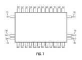
- FIG. 7illustrates a BASE-T magnetic package with two integrated common mode transformers.
- FIG. 8illustrates a bottom view of a BASE-T ICM package with four groups of pins.
- the present inventionrelates generally to communication systems and more specifically to a common mode circuit for a communication system.
- the following descriptionis presented to enable one of ordinary skill in the art to make and use the invention and is provided in the context of a patent application and its requirements.
- Various modifications to the preferred embodiments and the generic principles and features described hereinwill be readily apparent to those skilled in the art.
- the present inventionis not intended to be limited to the embodiments shown, but is to be accorded the widest scope consistent with the principles and features described herein.
- a circuit for a wireline systemincludes a twisted pair channel.
- the twisted pair channeldelivers a differential signal that includes a converter mode component.
- the circuitincludes at least one transformer coupled to the twisted pair channel and a transceiver coupled to the at least one transformer.
- the circuitfurther includes a common mode detection coupled to the transceiver for detecting a common mode component.
- the circuitdetects the common mode component. Accordingly, with common mode component detection capability, the common mode component of the differential can be analyzed for characterization purposes as well as for potential improvement in the system performance signal.
- FIG. 2shows a circuit 200 in accordance to an embodiment of the present invention.
- the circuit 200includes a twisted pair channel 210 , a common mode choke 220 , a differential transformer 230 and a transceiver 260 .
- the common mode choke 220is coupled to the twisted pair channel 210 and the differential transformer 230 .
- the differential transformer 230is coupled to the transceiver 260 via a common mode controller 255 .
- the twisted pair channel 210is a form of wiring in which two conductors (the forward and return conductors of a single circuit) are twisted together for the purpose of canceling out electromagnetic interference (EMI) from external sources, for instance, electromagnetic radiation from Unshielded Twisted Pair (UTP) cables, and crosstalk between neighboring pairs.
- EMIelectromagnetic interference
- UTPUnshielded Twisted Pair
- the common mode detector 255is shown in the transceiver 260 .
- the common mode component 240 of a differential signal that has leaked into the transceiver 260is extracted from the differential pair 250 .
- a way to extract the common mode component 240 from a differential pair 250is to tap the center point of impedance 235 that connects between the pair as shown in FIG. 2 .
- the center point of impedance 235is placed inside of the transceiver 260 .
- FIG. 3illustrates a way to provide a path to inject the common mode component 240 to the transceiver 260 .
- FIG. 3shows a common mode transformer 270 coupled to the differential transformer 230 and the common mode choke 220 for injecting the common mode component into the differential pair in order to facilitate proper detection.
- FIG. 4shows a common mode detection circuit 400 in accordance with an alternate embodiment of the present invention whereby a transformer configuration is introduced which provides a means of common mode measurement.
- the circuit 400includes a twisted pair channel 410 , a common mode choke 420 , a differential transformer 430 , a common mode transformer 440 , and a transceiver 450 .
- the common mode choke 420is coupled to the twisted pair channel 410 and the differential transformer 430 .
- the differential transformer 430is coupled to the common mode transformer 440 and the transceiver 450 whereby the common mode transformer 440 is coupled to the transceiver 450 .
- the common mode transformer 440provides for the detection and measurement of the common mode component.
- ESD or CDE eventsresult in large common mode voltages in a medium.
- the transceiver 140is isolated from the large common mode voltage on the cable as the transformer 130 rejects most of the common mode component while passing all the differential-mode signal.
- the common mode component of the cable sideis effectively passed to the transceiver 450 , thus becoming vulnerable to ESD/CDE events.
- the common mode transformer 440is selected such that its core 441 saturates in the presence of large input voltages, basically having a clipping effect, to protect against over voltage.
- a large input voltage due to electro-static charge accumulated on the cablecan reach or exceed few kV (e.g. 2000V).
- this common mode transformer 440can add a challenge for high density and/or price sensitive systems, making this solution not very attractive from practical implementation and production point of view.
- a solution to this problemis to integrate this transformer as an additional core to the package of the existing link transformer.
- an existing packagewill have three additional pins per common mode transformer, two for differential connection of wires and one for center tap of transformer for proper biasing, thereby resulting in some increase in the size of the package with minimal impact on board layout and price.
- FIG. 6Aillustrates a schematic view of a magnetic package with an integrated common mode transformer.
- 10GBASE-Twhere there are four pairs and thus four cores that include transformers 650 a - 650 d and four cores that include chokes 652 a - 652 d
- a total of 8 coresonly one core for the common mode transformer 660 is used to detect the line common mode. This only increases the total size and price of the new component by factor of 9/8 only ⁇ 12%.
- there may be requirements for redundancy of this common mode corewhich may lead to having 2 such cores and sensing common mode of two of the twisted pairs. In that case, an increase factor of 10/8 or 25% is contemplated.
- FIG. 5shows an example of an Ethernet BASE-T (e.g. 10GBASE-T) magnetic package 500 .
- Each input and output per pairhas three pins, two for differential connection of wires and one for center tap of transformer for proper biasing.
- the extra pinsIcm1, Ocm1+, Ocm1 ⁇
- FIG. 6Bshows the extra pins Icm1 610 , Ocm1+ 620 and Ocm1 ⁇ 630 .
- the extra pins 610 , 620 , 630can be placed anywhere on the top and bottom.
- FIG. 7shows the additional pins Icm1 710 , Ocm1+ 720 , Ocm1 ⁇ 730 and Icm2 740 , Ocm2+ 750 , Ocm2 ⁇ 760 on the sides.
- ICMIntegrated Connector Modules
- the integration of the common mode transformers in the ICMis desirable as the center tap of the transformer in the cable side that carries the common mode component does not come out as a pin in the ICMs and are terminated inside the package.
- signal pins connected to the boardare preferably all underneath the package. This is shown in FIG. 8 as the four groups of pins 810 , 820 , 830 , 840 are shown in the bottom view of an ICM 800 .
- two pins of the four pins in the sub groupsare differential signals and two are center taps of the same channel. Accordingly, the fifth channel for the common mode transformer output can be placed at the center of the four groups, as an example, and no input will be visible for the common mode transformer in this case.
- the center-tap termination for the common modecan be eliminated for the case of having a common mode transformer 440 connected to that center tap, if the other side of the transformer 440 is going to be terminated. Assuming that in most scenarios the center tap termination is different from 50 ohms and in most cases it is easier to have a 50 ohm termination, the transformer primary/secondary ratios can be adjusted to convert 50 ohms to any target value. Consequently, the addition of the common mode transformer 440 does not result in additional board components either.
- an implementation of the present inventionincludes a method of providing for a common mode detection circuit.
- the methodcomprises providing for a twisted pair channel, providing for a common mode choke coupled to the twisted pair channel, providing for at least one transformer coupled to the common mode choke, providing for a transceiver coupled to the at least one transformer and providing for a common mode component controller coupled to the at least one transformer and the transceiver.
- Varying embodiments of the present inventiondefine a unique common mode detection circuit for a communication system.
- the circuitdetects the common mode component. Accordingly, with common mode signal detection capability, the common mode component can be analyzed for characterization purposes as well as for potential improvement in the system performance.
Landscapes
- Engineering & Computer Science (AREA)
- Computer Networks & Wireless Communication (AREA)
- Signal Processing (AREA)
- Power Engineering (AREA)
- Multimedia (AREA)
- Dc Digital Transmission (AREA)
- Cable Transmission Systems, Equalization Of Radio And Reduction Of Echo (AREA)
- Noise Elimination (AREA)
Abstract
Description
Claims (24)
Priority Applications (2)
| Application Number | Priority Date | Filing Date | Title |
|---|---|---|---|
| US12/604,323US8928425B1 (en) | 2008-09-25 | 2009-10-22 | Common mode detector for a communication system |
| US13/965,635US9590695B1 (en) | 2008-09-25 | 2013-08-13 | Rejecting RF interference in communication systems |
Applications Claiming Priority (6)
| Application Number | Priority Date | Filing Date | Title |
|---|---|---|---|
| US9997908P | 2008-09-25 | 2008-09-25 | |
| US14163908P | 2008-12-30 | 2008-12-30 | |
| US14164008P | 2008-12-30 | 2008-12-30 | |
| US17339409P | 2009-04-28 | 2009-04-28 | |
| US55134009A | 2009-08-31 | 2009-08-31 | |
| US12/604,323US8928425B1 (en) | 2008-09-25 | 2009-10-22 | Common mode detector for a communication system |
Related Parent Applications (1)
| Application Number | Title | Priority Date | Filing Date |
|---|---|---|---|
| US55134009AContinuation | 2008-09-25 | 2009-08-31 |
Publications (1)
| Publication Number | Publication Date |
|---|---|
| US8928425B1true US8928425B1 (en) | 2015-01-06 |
Family
ID=46964234
Family Applications (3)
| Application Number | Title | Priority Date | Filing Date |
|---|---|---|---|
| US12/563,938Active2029-09-30US9912375B1 (en) | 2008-09-25 | 2009-09-21 | Cancellation of alien interference in communication systems |
| US12/604,343Active2030-04-10US8284007B1 (en) | 2008-09-25 | 2009-10-22 | Magnetic package for a communication system |
| US12/604,323Active2033-03-25US8928425B1 (en) | 2008-09-25 | 2009-10-22 | Common mode detector for a communication system |
Family Applications Before (2)
| Application Number | Title | Priority Date | Filing Date |
|---|---|---|---|
| US12/563,938Active2029-09-30US9912375B1 (en) | 2008-09-25 | 2009-09-21 | Cancellation of alien interference in communication systems |
| US12/604,343Active2030-04-10US8284007B1 (en) | 2008-09-25 | 2009-10-22 | Magnetic package for a communication system |
Country Status (1)
| Country | Link |
|---|---|
| US (3) | US9912375B1 (en) |
Cited By (6)
| Publication number | Priority date | Publication date | Assignee | Title |
|---|---|---|---|---|
| DE102014218874A1 (en)* | 2014-09-19 | 2016-03-24 | Forschungszentrum Jülich GmbH | High quality coil |
| US20170012677A1 (en)* | 2013-07-01 | 2017-01-12 | Texas Instruments Incorporated | Inductive structures with improved common mode transient immunity |
| US11290291B2 (en)* | 2018-07-31 | 2022-03-29 | Analog Devices International Unlimited Company | Power over data lines system with combined dc coupling and common mode termination circuitry |
| US11418369B2 (en)* | 2019-08-01 | 2022-08-16 | Analog Devices International Unlimited Company | Minimizing DC bias voltage difference across AC-blocking capacitors in PoDL system |
| US11467643B2 (en)* | 2015-05-08 | 2022-10-11 | Igor, Inc. | Power over ethernet system |
| US12143247B2 (en) | 2022-07-15 | 2024-11-12 | Aeonsemi, Inc. | Adaptive mode imbalance compensation |
Families Citing this family (23)
| Publication number | Priority date | Publication date | Assignee | Title |
|---|---|---|---|---|
| WO2011056970A2 (en) | 2009-11-06 | 2011-05-12 | Molex Incorporated | Mag-jack module |
| US8992248B2 (en) | 2009-11-06 | 2015-03-31 | Molex Incorporated | Modular jack with enhanced port isolation |
| US9118469B2 (en) | 2010-05-28 | 2015-08-25 | Aquantia Corp. | Reducing electromagnetic interference in a received signal |
| US8792597B2 (en) | 2010-06-18 | 2014-07-29 | Aquantia Corporation | Reducing electromagnetic interference in a receive signal with an analog correction signal |
| AT512064B1 (en)* | 2011-10-31 | 2015-11-15 | Fronius Int Gmbh | HIGH-FLOW TRANSFORMER, TRANSFORMER ELEMENT, CONTACT PLATE AND SECONDARY WINDING, AND METHOD FOR PRODUCING SUCH A HIGH-SPEED TRANSFORMER |
| US8903009B2 (en)* | 2012-01-06 | 2014-12-02 | Broadcom Corporation | Common-mode termination within communication systems |
| US8929468B1 (en)* | 2012-06-14 | 2015-01-06 | Aquantia Corp. | Common-mode detection with magnetic bypass |
| KR101428199B1 (en)* | 2012-10-22 | 2014-08-07 | 엘지이노텍 주식회사 | The common mode filter and the power supply device having the same |
| WO2016116912A1 (en) | 2015-01-25 | 2016-07-28 | Valens Semiconductor Ltd. | Fast adaptive mode-conversion digital canceller |
| US9621445B2 (en) | 2015-01-25 | 2017-04-11 | Valens Semiconductor Ltd. | Utilizing known data for status signaling |
| US10256920B2 (en) | 2015-01-25 | 2019-04-09 | Valens Semiconductor Ltd. | Mode-conversion digital canceller for high bandwidth differential signaling |
| US10171182B2 (en) | 2015-01-25 | 2019-01-01 | Valens Semiconductor Ltd. | Sending known data to support fast convergence |
| US9685991B2 (en) | 2015-01-25 | 2017-06-20 | Valens Semiconductor Ltd. | Reducing transmission rate to support fast convergence |
| CN106067778A (en)* | 2015-04-23 | 2016-11-02 | 松下知识产权经营株式会社 | Magnetism parts and electric circuit |
| US9397450B1 (en)* | 2015-06-12 | 2016-07-19 | Amphenol Corporation | Electrical connector with port light indicator |
| DE102016212991A1 (en)* | 2016-02-26 | 2017-08-31 | Volkswagen Aktiengesellschaft | Data transmission system, control unit and method for data transmission |
| IT201600088207A1 (en)* | 2016-08-30 | 2018-03-02 | St Microelectronics Srl | GALVANIC INSULATION CIRCUIT, CORRESPONDENT SYSTEM AND PROCEDURE |
| EP3503417B1 (en) | 2017-12-21 | 2020-10-28 | Nxp B.V. | Transceiver and system for electromagnetic emission detection |
| EP3503418A1 (en)* | 2017-12-21 | 2019-06-26 | Nxp B.V. | Transceiver and method of adjusting the tx signal of the transceiver for weakening emi |
| EP3915194B1 (en)* | 2019-01-22 | 2023-07-19 | Stmicroelectronics Sa | Method and device for phase detection of a signal via a hybrid coupler, using a test signal |
| US11228465B1 (en)* | 2019-03-22 | 2022-01-18 | Marvell Asia Pte, Ltd. | Rapid training method for high-speed ethernet |
| US10985801B1 (en)* | 2019-08-28 | 2021-04-20 | Marvell Asia Pte., Ltd. | Ethernet link transmit power method based on on-chip detected alien crosstalk feedback |
| JP7506588B2 (en)* | 2020-12-11 | 2024-06-26 | 日立Astemo株式会社 | Electronic Control Unit |
Citations (102)
| Publication number | Priority date | Publication date | Assignee | Title |
|---|---|---|---|---|
| US3506906A (en) | 1967-12-18 | 1970-04-14 | Rucker Co | Ground fault circuit interrupter with inadvertent ground sensor |
| US3671859A (en) | 1970-11-04 | 1972-06-20 | Gen Electric | Frequency transducer |
| US4797902A (en) | 1984-12-29 | 1989-01-10 | Sony Corporation | Digital signal transmission device |
| US4870370A (en) | 1988-02-19 | 1989-09-26 | Silicon Systems, Inc. | Method and apparatus for two stage automatic gain control |
| US5157690A (en) | 1990-10-30 | 1992-10-20 | Level One Communications, Inc. | Adaptive convergent decision feedback equalizer |
| US5283811A (en) | 1991-09-03 | 1994-02-01 | General Electric Company | Decision feedback equalization for digital cellular radio |
| US5550924A (en) | 1993-07-07 | 1996-08-27 | Picturetel Corporation | Reduction of background noise for speech enhancement |
| WO1997040587A1 (en) | 1996-04-19 | 1997-10-30 | Amati Communications Corporation | Radio frequency noise canceller |
| US5777692A (en) | 1994-12-29 | 1998-07-07 | Philips Electronics North America Corporation | Receiver based methods and devices for combating co-channel NTSC interference in digital transmission |
| US5832032A (en) | 1995-11-09 | 1998-11-03 | Northern Telecom Limited | Interference reduction in telecommunications systems |
| US5889511A (en) | 1997-01-17 | 1999-03-30 | Tritech Microelectronics International, Ltd. | Method and system for noise reduction for digitizing devices |
| US5910960A (en) | 1995-06-07 | 1999-06-08 | Discovision Associates | Signal processing apparatus and method |
| US5995566A (en) | 1995-11-04 | 1999-11-30 | Northern Telecom Limited | Interference reduction in telecommunication systems |
| US6011508A (en) | 1997-10-31 | 2000-01-04 | Magnemotion, Inc. | Accurate position-sensing and communications for guideway operated vehicles |
| US6035360A (en) | 1997-10-29 | 2000-03-07 | International Business Machines Corporation | Multi-port SRAM access control using time division multiplexed arbitration |
| US6052420A (en) | 1997-05-15 | 2000-04-18 | Northern Telecom Limited | Adaptive multiple sub-band common-mode RFI suppression |
| US6069917A (en) | 1997-05-23 | 2000-05-30 | Lucent Technologies Inc. | Blind training of a decision feedback equalizer |
| US6285718B1 (en) | 1997-02-28 | 2001-09-04 | Orckit Communication Ltd. | Adaptive noise canceller |
| US6385315B1 (en) | 1998-06-05 | 2002-05-07 | Mphase Corporation | Video voice separation system |
| US6424234B1 (en) | 1998-09-18 | 2002-07-23 | Greatbatch-Sierra, Inc. | Electromagnetic interference (emi) filter and process for providing electromagnetic compatibility of an electronic device while in the presence of an electromagnetic emitter operating at the same frequency |
| US6486746B1 (en) | 2000-06-30 | 2002-11-26 | Intel Corporation | Termination circuit for decoupling unused wires on a network device's unshielded twisted pair (UTP) cable |
| US20030186591A1 (en) | 1993-03-12 | 2003-10-02 | Cekan/Cdt A/S | Connector element for high-speed data communications |
| US20030223505A1 (en) | 1999-12-30 | 2003-12-04 | Rami Verbin | Data transceiver with filtering and precoding |
| US20030223488A1 (en) | 2002-04-04 | 2003-12-04 | Chunlin Li | Fast phase synchronization and retrieval of sequence components in three-phase networks |
| US20040010203A1 (en) | 2002-07-12 | 2004-01-15 | Bionova Technologies Inc. | Method and apparatus for the estimation of anesthetic depth using wavelet analysis of the electroencephalogram |
| US6683913B1 (en) | 1999-12-30 | 2004-01-27 | Tioga Technologies Inc. | Narrowband noise canceller |
| US20040023631A1 (en) | 2002-07-30 | 2004-02-05 | Deutsch Jeffrey T. | Method and system for rejecting noise in information communication |
| US6690739B1 (en) | 2000-01-14 | 2004-02-10 | Shou Yee Mui | Method for intersymbol interference compensation |
| US6711207B1 (en) | 1999-03-11 | 2004-03-23 | Globespanvirata, Inc. | System and method for reduced power consumption in digital subscriber line modems |
| US6734659B1 (en) | 2002-06-13 | 2004-05-11 | Mykrolis Corporation | Electronic interface for use with dual electrode capacitance diaphragm gauges |
| US6771720B1 (en) | 2001-03-30 | 2004-08-03 | Skyworks Solutions, Inc. | Amplification control scheme for a receiver |
| US20040164619A1 (en) | 2003-02-21 | 2004-08-26 | Parker Timothy J. | Connector module with embedded Power-Over-Ethernet functionality |
| US20040213366A1 (en) | 2002-07-02 | 2004-10-28 | Pioneer Corporation | Receiver with adjacent interfering wave elimination function |
| US20040239465A1 (en) | 2003-05-21 | 2004-12-02 | Bel Fuse, Inc. | LAN magnetic interface circuit |
| US20040252755A1 (en) | 1999-08-13 | 2004-12-16 | Broadcom Corporation | Decision feedback equalizer and precoder ramping circuit |
| US20040257743A1 (en) | 2003-06-19 | 2004-12-23 | Bel-Fuse, Inc. | LAN magnetic interface circuit with passive ESD protection |
| US20050018777A1 (en) | 2003-01-28 | 2005-01-27 | Kameran Azadet | Method and apparatus for reducing noise in an unbalanced channel using common mode component |
| US20050025266A1 (en) | 1998-11-11 | 2005-02-03 | Chan Kevin T. | Adaptive electronic transmission signal cancellation apparatus for full duplex communication |
| US20050053229A1 (en) | 2003-09-08 | 2005-03-10 | Tsatsanis Michail Konstantinos | Common mode noise cancellation |
| US20050097218A1 (en) | 2003-10-03 | 2005-05-05 | Dell Products L.P. | System, method & device for tuning a switched transmission line for ethernet local area network-on-motherboard (LOM) |
| US20050123081A1 (en) | 2003-12-05 | 2005-06-09 | Ramin Shirani | Low-power mixed-mode echo/crosstalk cancellation in wireline communications |
| US20050135489A1 (en) | 2003-12-17 | 2005-06-23 | Andrew Ho | Noise-tolerant signaling schemes supporting simplified timing and data recovery |
| US6924724B2 (en) | 2003-01-24 | 2005-08-02 | Solarflare Communications, Inc. | Method and apparatus for transformer bandwidth enhancement |
| US6934345B2 (en) | 2001-01-17 | 2005-08-23 | Adtran, Inc. | Apparatus, method and system for correlated noise reduction in a trellis coded environment |
| US20050203744A1 (en) | 2004-03-11 | 2005-09-15 | Denso Corporation | Method, device and program for extracting and recognizing voice |
| US6959056B2 (en) | 2000-06-09 | 2005-10-25 | Bell Canada | RFI canceller using narrowband and wideband noise estimators |
| US20050243483A1 (en) | 2004-04-28 | 2005-11-03 | Bel-Fuse | Differential electrical surge protection within a LAN magnetics interface circuit |
| US20060018388A1 (en) | 1998-10-30 | 2006-01-26 | Chan Kevin T | Reduction of aggregate EMI emissions of multiple transmitters |
| US6999504B1 (en) | 2000-11-21 | 2006-02-14 | Globespanvirata, Inc. | System and method for canceling crosstalk |
| US20060056503A1 (en)* | 2004-09-13 | 2006-03-16 | Regents Of The University Of Minnesota | Pipelined parallel decision feedback decoders for high-speed communication systems |
| US7026730B1 (en) | 2002-12-20 | 2006-04-11 | Cisco Technology, Inc. | Integrated connector unit |
| US7031402B2 (en) | 2001-06-12 | 2006-04-18 | Hitachi Kokusai Electric Inc. | Interference signal removal system |
| US20060159186A1 (en) | 2005-01-14 | 2006-07-20 | Piping Hot Networks Limited | Data, power and supervisory signaling over twisted pairs |
| US20060182014A1 (en) | 2005-02-14 | 2006-08-17 | Texas Instruments Incorporated | Apparatus for and method of characterization of ethernet cable impairments |
| US7103013B1 (en) | 2001-11-20 | 2006-09-05 | Silicon Image | Bidirectional bridge circuit having high common mode rejection and high input sensitivity |
| US20060256880A1 (en) | 2005-05-13 | 2006-11-16 | Frisch Arnold M | Automatic skew correction for differential signals |
| US7164764B2 (en) | 2002-11-07 | 2007-01-16 | Solarflare Communications, Inc. | Method and apparatus for precode crosstalk mitigation |
| US20070014378A1 (en) | 2005-07-13 | 2007-01-18 | Leanics Corporation | System and method for MIMO equalization for DSP transceivers |
| US7173992B2 (en) | 2001-12-11 | 2007-02-06 | Sasken Communication Technologies Limited | Method for synchronization in wireless systems using receive diversity |
| US20070081475A1 (en) | 2005-10-11 | 2007-04-12 | Teranetics, Inc. | Multiple modulation rate 10Gbase-T transmission |
| US20070146011A1 (en) | 2005-12-28 | 2007-06-28 | O'mahony Frank P | Duty cycle adjustment |
| US20070192505A1 (en) | 2006-02-13 | 2007-08-16 | Teranetics, Inc. | Auto-sequencing transmission speed of a data port |
| US20070258517A1 (en) | 2006-05-08 | 2007-11-08 | Micro Circuits Corporation | Adaptive error slicer and residual intersymbol interference estimator |
| US20070280388A1 (en) | 2006-05-31 | 2007-12-06 | Texas Instruments Incorporated | Apparatus for and method of canceller tap shutdown in a communication system |
| US7333603B1 (en) | 2000-05-12 | 2008-02-19 | National Semiconductor Corporation | System and method for adapting an analog echo canceller in a transceiver front end |
| USRE40149E1 (en) | 1999-12-30 | 2008-03-11 | Stmicroelectronics, N.V. | Method and apparatus for RF common-mode noise rejection in a DSL receiver |
| US20080089433A1 (en) | 2006-10-13 | 2008-04-17 | Jun Hyok Cho | Method and apparatus for adapting to dynamic channel conditions in a multi-channel communication system |
| US20080095283A1 (en) | 2006-10-19 | 2008-04-24 | Ehud Shoor | Techniques to reduce the impact of jitter on communications system performance |
| US20080107167A1 (en) | 2006-11-03 | 2008-05-08 | Hsu-Jung Tung | Data recovery apparatus and method |
| US20080160915A1 (en) | 2006-12-29 | 2008-07-03 | Texas Instruments Incorporated | Far-end crosstalk (fext) canceller |
| US20080198909A1 (en) | 2003-09-08 | 2008-08-21 | Michail Konstantinos Tsatsanis | Efficient multiple input multiple output signal processing method and apparatus |
| US20080267212A1 (en) | 2007-04-24 | 2008-10-30 | Philip John Crawley | Isolated Ethernet Physical Layer (PHY) |
| US7457386B1 (en) | 2000-05-12 | 2008-11-25 | National Semiconductor Corporation | System and method for cancelling signal echoes in a full-duplex transceiver front end |
| US7459982B2 (en) | 2006-09-27 | 2008-12-02 | Finisar Corporation | EMI reduction stage in a post-amplifier |
| US20090061808A1 (en) | 2007-08-28 | 2009-03-05 | Higgins Robert P | Adaptive rf canceller system and method |
| US20090097401A1 (en) | 2007-10-12 | 2009-04-16 | Wael William Diab | Method and system for configurable data rate thresholds for energy efficient ethernet |
| US20090097539A1 (en) | 2007-10-12 | 2009-04-16 | Harris Corporation | Communications system using adaptive filter and variable delay before adaptive filter taps |
| US7522928B2 (en) | 2003-10-24 | 2009-04-21 | Intel Corporation | Dynamic EMI (electromagnetic interference) management |
| US7542528B1 (en) | 2004-08-10 | 2009-06-02 | Marvell International Ltd. | Far end crosstalk mitigation in multiple-input multiple-output (MIMO) channels using partial maximum likelihood MIMO-DFE |
| US20090154455A1 (en) | 2007-12-17 | 2009-06-18 | Wael William Diab | Method And System For Near Continuous Data Rate Limit Adjustment Via A Plurality Of Link Variables In An Energy Efficient Network |
| US20090161781A1 (en) | 2007-12-21 | 2009-06-25 | Broadcom Corporation | Characterizing channel response using data tone decision feedback |
| US7634032B2 (en) | 2004-03-04 | 2009-12-15 | Adtran, Inc. | System and method for detecting non-linear distortion of signals communicated across telecommunication lines |
| US20100046543A1 (en) | 2008-08-11 | 2010-02-25 | Gavin Parnaby | Method of synchronization for low power idle |
| US20100073072A1 (en) | 2008-09-24 | 2010-03-25 | Sony Ericsson Mobile Communications Ab | Biasing arrangement, electronic apparatus, biasing method, and computer program |
| US20100074310A1 (en) | 2000-07-31 | 2010-03-25 | Pierte Roo | Active resistive summer for a transformer hybrid |
| US20100086019A1 (en) | 1998-11-13 | 2010-04-08 | Agazzi Oscar E | High-Speed Decoder for a Multi-Pair Gigabit Transceiver |
| US7706434B1 (en) | 2005-04-15 | 2010-04-27 | Aquantia Corporation | Method and apparatus for cancelling interference in a communication system |
| US7708595B2 (en) | 2008-09-10 | 2010-05-04 | Hon Hai Precision Ind. Co., Ltd. | Electrical connector system with magnetic module |
| US20100111202A1 (en) | 2008-10-30 | 2010-05-06 | Schley-May James T | Method and apparatus for generating a common-mode reference signal |
| US20100159866A1 (en) | 2008-12-23 | 2010-06-24 | Fudge Gerald L | Systems and methods for interference cancellation |
| US20110032048A1 (en) | 2009-08-10 | 2011-02-10 | National Taiwan University | Filtering device and differential signal transmission circuit capable of suppressing common-mode noises upon transmission of a deifferential signal |
| US20110069794A1 (en) | 2009-09-18 | 2011-03-24 | Mehdi Tavassoli Kilani | Method and system for interference cancellation |
| US20110106459A1 (en) | 2009-10-29 | 2011-05-05 | Northrop Grumman Corporation | In-situ optical crack measurement using a dot pattern |
| WO2011056970A2 (en) | 2009-11-06 | 2011-05-12 | Molex Incorporated | Mag-jack module |
| US20110212692A1 (en) | 2010-02-26 | 2011-09-01 | Intersil Americas Inc. | Cascaded Filter Based Noise and Interference Canceller |
| US20110256857A1 (en) | 2010-04-20 | 2011-10-20 | Intersil Americas Inc. | Systems and Methods for Improving Antenna Isolation Using Signal Cancellation |
| US20110293041A1 (en) | 2010-05-25 | 2011-12-01 | Lei Luo | Receiver Resistor Network for Common-Mode Signaling |
| US20110296267A1 (en) | 2010-05-28 | 2011-12-01 | Teranetics, Inc. | Reducing Electromagnetic Interference in a Received Signal |
| US8094546B2 (en) | 2007-06-13 | 2012-01-10 | Lantiq Deutschland Gmbh | Device and method for compensating crosstalk in transmission links |
| US8139602B2 (en) | 2004-07-28 | 2012-03-20 | Rockstar Bidco, LP | System, method and device for high bit rate data communication over twisted pair cables |
| US8331508B2 (en) | 2010-07-14 | 2012-12-11 | Applied Micro Circuits Corporation | Narrowband interference cancellation method and circuit |
| US8625704B1 (en) | 2008-09-25 | 2014-01-07 | Aquantia Corporation | Rejecting RF interference in communication systems |
- 2009
- 2009-09-21USUS12/563,938patent/US9912375B1/enactiveActive
- 2009-10-22USUS12/604,343patent/US8284007B1/enactiveActive
- 2009-10-22USUS12/604,323patent/US8928425B1/enactiveActive
Patent Citations (111)
| Publication number | Priority date | Publication date | Assignee | Title |
|---|---|---|---|---|
| US3506906A (en) | 1967-12-18 | 1970-04-14 | Rucker Co | Ground fault circuit interrupter with inadvertent ground sensor |
| US3671859A (en) | 1970-11-04 | 1972-06-20 | Gen Electric | Frequency transducer |
| US4797902A (en) | 1984-12-29 | 1989-01-10 | Sony Corporation | Digital signal transmission device |
| US4870370A (en) | 1988-02-19 | 1989-09-26 | Silicon Systems, Inc. | Method and apparatus for two stage automatic gain control |
| US5157690A (en) | 1990-10-30 | 1992-10-20 | Level One Communications, Inc. | Adaptive convergent decision feedback equalizer |
| US5283811A (en) | 1991-09-03 | 1994-02-01 | General Electric Company | Decision feedback equalization for digital cellular radio |
| US20030186591A1 (en) | 1993-03-12 | 2003-10-02 | Cekan/Cdt A/S | Connector element for high-speed data communications |
| US5550924A (en) | 1993-07-07 | 1996-08-27 | Picturetel Corporation | Reduction of background noise for speech enhancement |
| US5777692A (en) | 1994-12-29 | 1998-07-07 | Philips Electronics North America Corporation | Receiver based methods and devices for combating co-channel NTSC interference in digital transmission |
| US5910960A (en) | 1995-06-07 | 1999-06-08 | Discovision Associates | Signal processing apparatus and method |
| US5995566A (en) | 1995-11-04 | 1999-11-30 | Northern Telecom Limited | Interference reduction in telecommunication systems |
| US5832032A (en) | 1995-11-09 | 1998-11-03 | Northern Telecom Limited | Interference reduction in telecommunications systems |
| WO1997040587A1 (en) | 1996-04-19 | 1997-10-30 | Amati Communications Corporation | Radio frequency noise canceller |
| US5995567A (en) | 1996-04-19 | 1999-11-30 | Texas Instruments Incorporated | Radio frequency noise canceller |
| US5889511A (en) | 1997-01-17 | 1999-03-30 | Tritech Microelectronics International, Ltd. | Method and system for noise reduction for digitizing devices |
| US6285718B1 (en) | 1997-02-28 | 2001-09-04 | Orckit Communication Ltd. | Adaptive noise canceller |
| US6052420A (en) | 1997-05-15 | 2000-04-18 | Northern Telecom Limited | Adaptive multiple sub-band common-mode RFI suppression |
| US6069917A (en) | 1997-05-23 | 2000-05-30 | Lucent Technologies Inc. | Blind training of a decision feedback equalizer |
| US6035360A (en) | 1997-10-29 | 2000-03-07 | International Business Machines Corporation | Multi-port SRAM access control using time division multiplexed arbitration |
| US6011508A (en) | 1997-10-31 | 2000-01-04 | Magnemotion, Inc. | Accurate position-sensing and communications for guideway operated vehicles |
| US6385315B1 (en) | 1998-06-05 | 2002-05-07 | Mphase Corporation | Video voice separation system |
| US6424234B1 (en) | 1998-09-18 | 2002-07-23 | Greatbatch-Sierra, Inc. | Electromagnetic interference (emi) filter and process for providing electromagnetic compatibility of an electronic device while in the presence of an electromagnetic emitter operating at the same frequency |
| US20060018388A1 (en) | 1998-10-30 | 2006-01-26 | Chan Kevin T | Reduction of aggregate EMI emissions of multiple transmitters |
| US20050025266A1 (en) | 1998-11-11 | 2005-02-03 | Chan Kevin T. | Adaptive electronic transmission signal cancellation apparatus for full duplex communication |
| US7492840B2 (en) | 1998-11-11 | 2009-02-17 | Broadcom Corporation | Adaptive electronic transmission signal cancellation apparatus for full duplex communication |
| US20100086019A1 (en) | 1998-11-13 | 2010-04-08 | Agazzi Oscar E | High-Speed Decoder for a Multi-Pair Gigabit Transceiver |
| US6711207B1 (en) | 1999-03-11 | 2004-03-23 | Globespanvirata, Inc. | System and method for reduced power consumption in digital subscriber line modems |
| US20040252755A1 (en) | 1999-08-13 | 2004-12-16 | Broadcom Corporation | Decision feedback equalizer and precoder ramping circuit |
| US20030223505A1 (en) | 1999-12-30 | 2003-12-04 | Rami Verbin | Data transceiver with filtering and precoding |
| USRE40149E1 (en) | 1999-12-30 | 2008-03-11 | Stmicroelectronics, N.V. | Method and apparatus for RF common-mode noise rejection in a DSL receiver |
| US6683913B1 (en) | 1999-12-30 | 2004-01-27 | Tioga Technologies Inc. | Narrowband noise canceller |
| US7200180B2 (en) | 1999-12-30 | 2007-04-03 | Tioga Technologies, Inc. | Data transceiver with filtering and precoding |
| US6690739B1 (en) | 2000-01-14 | 2004-02-10 | Shou Yee Mui | Method for intersymbol interference compensation |
| US7457386B1 (en) | 2000-05-12 | 2008-11-25 | National Semiconductor Corporation | System and method for cancelling signal echoes in a full-duplex transceiver front end |
| US7333603B1 (en) | 2000-05-12 | 2008-02-19 | National Semiconductor Corporation | System and method for adapting an analog echo canceller in a transceiver front end |
| US6959056B2 (en) | 2000-06-09 | 2005-10-25 | Bell Canada | RFI canceller using narrowband and wideband noise estimators |
| US6486746B1 (en) | 2000-06-30 | 2002-11-26 | Intel Corporation | Termination circuit for decoupling unused wires on a network device's unshielded twisted pair (UTP) cable |
| US20100074310A1 (en) | 2000-07-31 | 2010-03-25 | Pierte Roo | Active resistive summer for a transformer hybrid |
| US6999504B1 (en) | 2000-11-21 | 2006-02-14 | Globespanvirata, Inc. | System and method for canceling crosstalk |
| US6934345B2 (en) | 2001-01-17 | 2005-08-23 | Adtran, Inc. | Apparatus, method and system for correlated noise reduction in a trellis coded environment |
| US6771720B1 (en) | 2001-03-30 | 2004-08-03 | Skyworks Solutions, Inc. | Amplification control scheme for a receiver |
| US7031402B2 (en) | 2001-06-12 | 2006-04-18 | Hitachi Kokusai Electric Inc. | Interference signal removal system |
| US7103013B1 (en) | 2001-11-20 | 2006-09-05 | Silicon Image | Bidirectional bridge circuit having high common mode rejection and high input sensitivity |
| US7173992B2 (en) | 2001-12-11 | 2007-02-06 | Sasken Communication Technologies Limited | Method for synchronization in wireless systems using receive diversity |
| US20030223488A1 (en) | 2002-04-04 | 2003-12-04 | Chunlin Li | Fast phase synchronization and retrieval of sequence components in three-phase networks |
| US7180940B2 (en) | 2002-04-04 | 2007-02-20 | Chunlin Li | Fast phase synchronization and retrieval of sequence components in three-phase networks |
| US6734659B1 (en) | 2002-06-13 | 2004-05-11 | Mykrolis Corporation | Electronic interface for use with dual electrode capacitance diaphragm gauges |
| US20040213366A1 (en) | 2002-07-02 | 2004-10-28 | Pioneer Corporation | Receiver with adjacent interfering wave elimination function |
| US20040010203A1 (en) | 2002-07-12 | 2004-01-15 | Bionova Technologies Inc. | Method and apparatus for the estimation of anesthetic depth using wavelet analysis of the electroencephalogram |
| US20040023631A1 (en) | 2002-07-30 | 2004-02-05 | Deutsch Jeffrey T. | Method and system for rejecting noise in information communication |
| US7164764B2 (en) | 2002-11-07 | 2007-01-16 | Solarflare Communications, Inc. | Method and apparatus for precode crosstalk mitigation |
| US7026730B1 (en) | 2002-12-20 | 2006-04-11 | Cisco Technology, Inc. | Integrated connector unit |
| US6924724B2 (en) | 2003-01-24 | 2005-08-02 | Solarflare Communications, Inc. | Method and apparatus for transformer bandwidth enhancement |
| US20050018777A1 (en) | 2003-01-28 | 2005-01-27 | Kameran Azadet | Method and apparatus for reducing noise in an unbalanced channel using common mode component |
| US20040164619A1 (en) | 2003-02-21 | 2004-08-26 | Parker Timothy J. | Connector module with embedded Power-Over-Ethernet functionality |
| US7123117B2 (en) | 2003-05-21 | 2006-10-17 | Bel-Fuse Inc. | LAN magnetic interface circuit |
| US20040239465A1 (en) | 2003-05-21 | 2004-12-02 | Bel Fuse, Inc. | LAN magnetic interface circuit |
| US20040257743A1 (en) | 2003-06-19 | 2004-12-23 | Bel-Fuse, Inc. | LAN magnetic interface circuit with passive ESD protection |
| US20050053229A1 (en) | 2003-09-08 | 2005-03-10 | Tsatsanis Michail Konstantinos | Common mode noise cancellation |
| US20080198909A1 (en) | 2003-09-08 | 2008-08-21 | Michail Konstantinos Tsatsanis | Efficient multiple input multiple output signal processing method and apparatus |
| US7315592B2 (en) | 2003-09-08 | 2008-01-01 | Aktino, Inc. | Common mode noise cancellation |
| US20050097218A1 (en) | 2003-10-03 | 2005-05-05 | Dell Products L.P. | System, method & device for tuning a switched transmission line for ethernet local area network-on-motherboard (LOM) |
| US7522928B2 (en) | 2003-10-24 | 2009-04-21 | Intel Corporation | Dynamic EMI (electromagnetic interference) management |
| US20050123081A1 (en) | 2003-12-05 | 2005-06-09 | Ramin Shirani | Low-power mixed-mode echo/crosstalk cancellation in wireline communications |
| US20050135489A1 (en) | 2003-12-17 | 2005-06-23 | Andrew Ho | Noise-tolerant signaling schemes supporting simplified timing and data recovery |
| US7634032B2 (en) | 2004-03-04 | 2009-12-15 | Adtran, Inc. | System and method for detecting non-linear distortion of signals communicated across telecommunication lines |
| US7440892B2 (en) | 2004-03-11 | 2008-10-21 | Denso Corporation | Method, device and program for extracting and recognizing voice |
| US20050203744A1 (en) | 2004-03-11 | 2005-09-15 | Denso Corporation | Method, device and program for extracting and recognizing voice |
| US20050243483A1 (en) | 2004-04-28 | 2005-11-03 | Bel-Fuse | Differential electrical surge protection within a LAN magnetics interface circuit |
| US8139602B2 (en) | 2004-07-28 | 2012-03-20 | Rockstar Bidco, LP | System, method and device for high bit rate data communication over twisted pair cables |
| US7542528B1 (en) | 2004-08-10 | 2009-06-02 | Marvell International Ltd. | Far end crosstalk mitigation in multiple-input multiple-output (MIMO) channels using partial maximum likelihood MIMO-DFE |
| US20060056503A1 (en)* | 2004-09-13 | 2006-03-16 | Regents Of The University Of Minnesota | Pipelined parallel decision feedback decoders for high-speed communication systems |
| US20060159186A1 (en) | 2005-01-14 | 2006-07-20 | Piping Hot Networks Limited | Data, power and supervisory signaling over twisted pairs |
| US7656956B2 (en) | 2005-01-14 | 2010-02-02 | Motorola, Inc. | Data, power and supervisory signaling over twisted pairs |
| US20060182014A1 (en) | 2005-02-14 | 2006-08-17 | Texas Instruments Incorporated | Apparatus for and method of characterization of ethernet cable impairments |
| US7706434B1 (en) | 2005-04-15 | 2010-04-27 | Aquantia Corporation | Method and apparatus for cancelling interference in a communication system |
| US20060256880A1 (en) | 2005-05-13 | 2006-11-16 | Frisch Arnold M | Automatic skew correction for differential signals |
| US20070014378A1 (en) | 2005-07-13 | 2007-01-18 | Leanics Corporation | System and method for MIMO equalization for DSP transceivers |
| US20070081475A1 (en) | 2005-10-11 | 2007-04-12 | Teranetics, Inc. | Multiple modulation rate 10Gbase-T transmission |
| US20070146011A1 (en) | 2005-12-28 | 2007-06-28 | O'mahony Frank P | Duty cycle adjustment |
| US20070192505A1 (en) | 2006-02-13 | 2007-08-16 | Teranetics, Inc. | Auto-sequencing transmission speed of a data port |
| US20070258517A1 (en) | 2006-05-08 | 2007-11-08 | Micro Circuits Corporation | Adaptive error slicer and residual intersymbol interference estimator |
| US20070280388A1 (en) | 2006-05-31 | 2007-12-06 | Texas Instruments Incorporated | Apparatus for and method of canceller tap shutdown in a communication system |
| US7459982B2 (en) | 2006-09-27 | 2008-12-02 | Finisar Corporation | EMI reduction stage in a post-amplifier |
| US20080089433A1 (en) | 2006-10-13 | 2008-04-17 | Jun Hyok Cho | Method and apparatus for adapting to dynamic channel conditions in a multi-channel communication system |
| US20080095283A1 (en) | 2006-10-19 | 2008-04-24 | Ehud Shoor | Techniques to reduce the impact of jitter on communications system performance |
| US20080107167A1 (en) | 2006-11-03 | 2008-05-08 | Hsu-Jung Tung | Data recovery apparatus and method |
| US20080160915A1 (en) | 2006-12-29 | 2008-07-03 | Texas Instruments Incorporated | Far-end crosstalk (fext) canceller |
| US20080267212A1 (en) | 2007-04-24 | 2008-10-30 | Philip John Crawley | Isolated Ethernet Physical Layer (PHY) |
| US8094546B2 (en) | 2007-06-13 | 2012-01-10 | Lantiq Deutschland Gmbh | Device and method for compensating crosstalk in transmission links |
| US20090061808A1 (en) | 2007-08-28 | 2009-03-05 | Higgins Robert P | Adaptive rf canceller system and method |
| US20090097401A1 (en) | 2007-10-12 | 2009-04-16 | Wael William Diab | Method and system for configurable data rate thresholds for energy efficient ethernet |
| US20090097539A1 (en) | 2007-10-12 | 2009-04-16 | Harris Corporation | Communications system using adaptive filter and variable delay before adaptive filter taps |
| US20090154455A1 (en) | 2007-12-17 | 2009-06-18 | Wael William Diab | Method And System For Near Continuous Data Rate Limit Adjustment Via A Plurality Of Link Variables In An Energy Efficient Network |
| US20090161781A1 (en) | 2007-12-21 | 2009-06-25 | Broadcom Corporation | Characterizing channel response using data tone decision feedback |
| US20100046543A1 (en) | 2008-08-11 | 2010-02-25 | Gavin Parnaby | Method of synchronization for low power idle |
| US7708595B2 (en) | 2008-09-10 | 2010-05-04 | Hon Hai Precision Ind. Co., Ltd. | Electrical connector system with magnetic module |
| US20100073072A1 (en) | 2008-09-24 | 2010-03-25 | Sony Ericsson Mobile Communications Ab | Biasing arrangement, electronic apparatus, biasing method, and computer program |
| US8625704B1 (en) | 2008-09-25 | 2014-01-07 | Aquantia Corporation | Rejecting RF interference in communication systems |
| US8472532B2 (en) | 2008-10-30 | 2013-06-25 | 2Wire, Inc. | Method and apparatus for generating a common-mode reference signal |
| US20100111202A1 (en) | 2008-10-30 | 2010-05-06 | Schley-May James T | Method and apparatus for generating a common-mode reference signal |
| US20100159866A1 (en) | 2008-12-23 | 2010-06-24 | Fudge Gerald L | Systems and methods for interference cancellation |
| US20110032048A1 (en) | 2009-08-10 | 2011-02-10 | National Taiwan University | Filtering device and differential signal transmission circuit capable of suppressing common-mode noises upon transmission of a deifferential signal |
| US20110069794A1 (en) | 2009-09-18 | 2011-03-24 | Mehdi Tavassoli Kilani | Method and system for interference cancellation |
| US20110106459A1 (en) | 2009-10-29 | 2011-05-05 | Northrop Grumman Corporation | In-situ optical crack measurement using a dot pattern |
| WO2011056970A2 (en) | 2009-11-06 | 2011-05-12 | Molex Incorporated | Mag-jack module |
| US20110212692A1 (en) | 2010-02-26 | 2011-09-01 | Intersil Americas Inc. | Cascaded Filter Based Noise and Interference Canceller |
| US20110256857A1 (en) | 2010-04-20 | 2011-10-20 | Intersil Americas Inc. | Systems and Methods for Improving Antenna Isolation Using Signal Cancellation |
| US20110293041A1 (en) | 2010-05-25 | 2011-12-01 | Lei Luo | Receiver Resistor Network for Common-Mode Signaling |
| US20110296267A1 (en) | 2010-05-28 | 2011-12-01 | Teranetics, Inc. | Reducing Electromagnetic Interference in a Received Signal |
| US8331508B2 (en) | 2010-07-14 | 2012-12-11 | Applied Micro Circuits Corporation | Narrowband interference cancellation method and circuit |
Non-Patent Citations (5)
| Title |
|---|
| U.S. Appl. No. 12/563,938, filed Sep. 21, 2009, Sedarat. |
| U.S. Appl. No. 12/604,343, filed Oct. 22, 2009, Farjadrad et al. |
| U.S. Appl. No. 12/604,351, filed Oct. 22, 2009, Sedarat et al. |
| U.S. Appl. No. 12/604,358, filed Oct. 22, 2009, Sedarat et al. |
| U.S. Appl. No. 12/977,844, filed Dec. 23, 2010, Sedarat. |
Cited By (8)
| Publication number | Priority date | Publication date | Assignee | Title |
|---|---|---|---|---|
| US20170012677A1 (en)* | 2013-07-01 | 2017-01-12 | Texas Instruments Incorporated | Inductive structures with improved common mode transient immunity |
| US9866283B2 (en)* | 2013-07-01 | 2018-01-09 | Texas Instruments Incorporated | Inductive structures with improved common mode transient immunity |
| US10320448B2 (en) | 2013-07-01 | 2019-06-11 | Texas Instruments Incorporated | Inductive structures with improved common mode transient immunity |
| DE102014218874A1 (en)* | 2014-09-19 | 2016-03-24 | Forschungszentrum Jülich GmbH | High quality coil |
| US11467643B2 (en)* | 2015-05-08 | 2022-10-11 | Igor, Inc. | Power over ethernet system |
| US11290291B2 (en)* | 2018-07-31 | 2022-03-29 | Analog Devices International Unlimited Company | Power over data lines system with combined dc coupling and common mode termination circuitry |
| US11418369B2 (en)* | 2019-08-01 | 2022-08-16 | Analog Devices International Unlimited Company | Minimizing DC bias voltage difference across AC-blocking capacitors in PoDL system |
| US12143247B2 (en) | 2022-07-15 | 2024-11-12 | Aeonsemi, Inc. | Adaptive mode imbalance compensation |
Also Published As
| Publication number | Publication date |
|---|---|
| US9912375B1 (en) | 2018-03-06 |
| US8284007B1 (en) | 2012-10-09 |
Similar Documents
| Publication | Publication Date | Title |
|---|---|---|
| US8928425B1 (en) | Common mode detector for a communication system | |
| US5587692A (en) | Common mode current cancellation in twisted pairs | |
| US7485010B2 (en) | Modular connector exhibiting quad reactance balance functionality | |
| KR101521815B1 (en) | Method and system for reducing common mode signal generation within a plug/jack connection | |
| US8674223B2 (en) | High speed data cable with impedance correction | |
| US6541878B1 (en) | Integrated RJ-45 magnetics with phantom power provision | |
| US7449639B2 (en) | Shielded flat pair cable architecture | |
| US4733389A (en) | Drop cable for a local area network | |
| US10333742B1 (en) | Termination for wire pair carrying DC and differential signals using isolation transformer with split primary and secondary windings | |
| US8674225B2 (en) | Economical boosted high speed data cable | |
| US8076990B2 (en) | Communications medium connector with integrated common-mode noise suppression | |
| US6492880B1 (en) | Common mode termination | |
| US8674226B2 (en) | High speed data cable including a boost device for generating a differential signal | |
| JPH11505677A (en) | Electromagnetic interference isolator | |
| US10425237B1 (en) | Termination for wire pair carrying DC and differential signals | |
| JP3103748B2 (en) | Circuit for wideband video transmission via unshielded twisted pair | |
| US7575478B1 (en) | High frequency connector having common mode choke coil | |
| US20120012359A1 (en) | Low cost high speed data cable | |
| US10382216B1 (en) | Termination for wire pair carrying DC and differential signals | |
| US20150194719A1 (en) | Cable with connector | |
| US10587424B1 (en) | Power over data lines system using power supply coupled to end of winding of isolation transformer | |
| US5548254A (en) | Balanced-to-unbalanced transformer | |
| US8929468B1 (en) | Common-mode detection with magnetic bypass | |
| US20060121801A1 (en) | High speed wired media connector with symmetric PCB interface | |
| CN103022818A (en) | Electric connector |
Legal Events
| Date | Code | Title | Description |
|---|---|---|---|
| STCF | Information on status: patent grant | Free format text:PATENTED CASE | |
| FEPP | Fee payment procedure | Free format text:SURCHARGE FOR LATE PAYMENT, SMALL ENTITY (ORIGINAL EVENT CODE: M2554) | |
| MAFP | Maintenance fee payment | Free format text:PAYMENT OF MAINTENANCE FEE, 4TH YR, SMALL ENTITY (ORIGINAL EVENT CODE: M2551) Year of fee payment:4 | |
| AS | Assignment | Owner name:CAVIUM INTERNATIONAL, CAYMAN ISLANDS Free format text:ASSIGNMENT OF ASSIGNORS INTEREST;ASSIGNOR:AQUANTIA CORPORATION;REEL/FRAME:051945/0520 Effective date:20191231 | |
| FEPP | Fee payment procedure | Free format text:ENTITY STATUS SET TO UNDISCOUNTED (ORIGINAL EVENT CODE: BIG.); ENTITY STATUS OF PATENT OWNER: LARGE ENTITY | |
| AS | Assignment | Owner name:MARVELL ASIA PTE, LTD., SINGAPORE Free format text:ASSIGNMENT OF ASSIGNORS INTEREST;ASSIGNOR:CAVIUM INTERNATIONAL;REEL/FRAME:053179/0320 Effective date:20191231 | |
| MAFP | Maintenance fee payment | Free format text:PAYMENT OF MAINTENANCE FEE, 8TH YEAR, LARGE ENTITY (ORIGINAL EVENT CODE: M1552); ENTITY STATUS OF PATENT OWNER: LARGE ENTITY Year of fee payment:8 |