US8928061B2 - Three dimensional NAND device with silicide containing floating gates - Google Patents
Three dimensional NAND device with silicide containing floating gatesDownload PDFInfo
- Publication number
- US8928061B2 US8928061B2US14/190,974US201414190974AUS8928061B2US 8928061 B2US8928061 B2US 8928061B2US 201414190974 AUS201414190974 AUS 201414190974AUS 8928061 B2US8928061 B2US 8928061B2
- Authority
- US
- United States
- Prior art keywords
- charge storage
- layer
- nand string
- device level
- substrate
- Prior art date
- Legal status (The legal status is an assumption and is not a legal conclusion. Google has not performed a legal analysis and makes no representation as to the accuracy of the status listed.)
- Active
Links
Images


Classifications
- H—ELECTRICITY
- H10—SEMICONDUCTOR DEVICES; ELECTRIC SOLID-STATE DEVICES NOT OTHERWISE PROVIDED FOR
- H10B—ELECTRONIC MEMORY DEVICES
- H10B41/00—Electrically erasable-and-programmable ROM [EEPROM] devices comprising floating gates
- H10B41/20—Electrically erasable-and-programmable ROM [EEPROM] devices comprising floating gates characterised by three-dimensional arrangements, e.g. with cells on different height levels
- H10B41/23—Electrically erasable-and-programmable ROM [EEPROM] devices comprising floating gates characterised by three-dimensional arrangements, e.g. with cells on different height levels with source and drain on different levels, e.g. with sloping channels
- H10B41/27—Electrically erasable-and-programmable ROM [EEPROM] devices comprising floating gates characterised by three-dimensional arrangements, e.g. with cells on different height levels with source and drain on different levels, e.g. with sloping channels the channels comprising vertical portions, e.g. U-shaped channels
- H—ELECTRICITY
- H01—ELECTRIC ELEMENTS
- H01L—SEMICONDUCTOR DEVICES NOT COVERED BY CLASS H10
- H01L21/00—Processes or apparatus adapted for the manufacture or treatment of semiconductor or solid state devices or of parts thereof
- H01L21/02—Manufacture or treatment of semiconductor devices or of parts thereof
- H01L21/04—Manufacture or treatment of semiconductor devices or of parts thereof the devices having potential barriers, e.g. a PN junction, depletion layer or carrier concentration layer
- H01L21/18—Manufacture or treatment of semiconductor devices or of parts thereof the devices having potential barriers, e.g. a PN junction, depletion layer or carrier concentration layer the devices having semiconductor bodies comprising elements of Group IV of the Periodic Table or AIIIBV compounds with or without impurities, e.g. doping materials
- H01L21/30—Treatment of semiconductor bodies using processes or apparatus not provided for in groups H01L21/20 - H01L21/26
- H01L21/31—Treatment of semiconductor bodies using processes or apparatus not provided for in groups H01L21/20 - H01L21/26 to form insulating layers thereon, e.g. for masking or by using photolithographic techniques; After treatment of these layers; Selection of materials for these layers
- H01L21/3205—Deposition of non-insulating-, e.g. conductive- or resistive-, layers on insulating layers; After-treatment of these layers
- H01L21/32051—Deposition of metallic or metal-silicide layers
- H01L21/32053—Deposition of metallic or metal-silicide layers of metal-silicide layers
- H—ELECTRICITY
- H10—SEMICONDUCTOR DEVICES; ELECTRIC SOLID-STATE DEVICES NOT OTHERWISE PROVIDED FOR
- H10B—ELECTRONIC MEMORY DEVICES
- H10B41/00—Electrically erasable-and-programmable ROM [EEPROM] devices comprising floating gates
- H10B41/20—Electrically erasable-and-programmable ROM [EEPROM] devices comprising floating gates characterised by three-dimensional arrangements, e.g. with cells on different height levels
- H—ELECTRICITY
- H10—SEMICONDUCTOR DEVICES; ELECTRIC SOLID-STATE DEVICES NOT OTHERWISE PROVIDED FOR
- H10B—ELECTRONIC MEMORY DEVICES
- H10B43/00—EEPROM devices comprising charge-trapping gate insulators
- H10B43/20—EEPROM devices comprising charge-trapping gate insulators characterised by three-dimensional arrangements, e.g. with cells on different height levels
- H10B43/23—EEPROM devices comprising charge-trapping gate insulators characterised by three-dimensional arrangements, e.g. with cells on different height levels with source and drain on different levels, e.g. with sloping channels
- H10B43/27—EEPROM devices comprising charge-trapping gate insulators characterised by three-dimensional arrangements, e.g. with cells on different height levels with source and drain on different levels, e.g. with sloping channels the channels comprising vertical portions, e.g. U-shaped channels
- H—ELECTRICITY
- H10—SEMICONDUCTOR DEVICES; ELECTRIC SOLID-STATE DEVICES NOT OTHERWISE PROVIDED FOR
- H10D—INORGANIC ELECTRIC SEMICONDUCTOR DEVICES
- H10D30/00—Field-effect transistors [FET]
- H10D30/01—Manufacture or treatment
- H10D30/021—Manufacture or treatment of FETs having insulated gates [IGFET]
- H10D30/0411—Manufacture or treatment of FETs having insulated gates [IGFET] of FETs having floating gates
- H—ELECTRICITY
- H10—SEMICONDUCTOR DEVICES; ELECTRIC SOLID-STATE DEVICES NOT OTHERWISE PROVIDED FOR
- H10D—INORGANIC ELECTRIC SEMICONDUCTOR DEVICES
- H10D30/00—Field-effect transistors [FET]
- H10D30/01—Manufacture or treatment
- H10D30/021—Manufacture or treatment of FETs having insulated gates [IGFET]
- H10D30/0413—Manufacture or treatment of FETs having insulated gates [IGFET] of FETs having charge-trapping gate insulators, e.g. MNOS transistors
- H—ELECTRICITY
- H10—SEMICONDUCTOR DEVICES; ELECTRIC SOLID-STATE DEVICES NOT OTHERWISE PROVIDED FOR
- H10D—INORGANIC ELECTRIC SEMICONDUCTOR DEVICES
- H10D30/00—Field-effect transistors [FET]
- H10D30/60—Insulated-gate field-effect transistors [IGFET]
- H10D30/68—Floating-gate IGFETs
- H10D30/689—Vertical floating-gate IGFETs
- H—ELECTRICITY
- H10—SEMICONDUCTOR DEVICES; ELECTRIC SOLID-STATE DEVICES NOT OTHERWISE PROVIDED FOR
- H10D—INORGANIC ELECTRIC SEMICONDUCTOR DEVICES
- H10D30/00—Field-effect transistors [FET]
- H10D30/60—Insulated-gate field-effect transistors [IGFET]
- H10D30/69—IGFETs having charge trapping gate insulators, e.g. MNOS transistors
- H10D30/693—Vertical IGFETs having charge trapping gate insulators
- H—ELECTRICITY
- H10—SEMICONDUCTOR DEVICES; ELECTRIC SOLID-STATE DEVICES NOT OTHERWISE PROVIDED FOR
- H10D—INORGANIC ELECTRIC SEMICONDUCTOR DEVICES
- H10D64/00—Electrodes of devices having potential barriers
- H10D64/01—Manufacture or treatment
- H10D64/031—Manufacture or treatment of data-storage electrodes
- H10D64/035—Manufacture or treatment of data-storage electrodes comprising conductor-insulator-conductor-insulator-semiconductor structures
- H—ELECTRICITY
- H10—SEMICONDUCTOR DEVICES; ELECTRIC SOLID-STATE DEVICES NOT OTHERWISE PROVIDED FOR
- H10D—INORGANIC ELECTRIC SEMICONDUCTOR DEVICES
- H10D64/00—Electrodes of devices having potential barriers
- H10D64/60—Electrodes characterised by their materials
- H10D64/66—Electrodes having a conductor capacitively coupled to a semiconductor by an insulator, e.g. MIS electrodes
- H10D64/661—Electrodes having a conductor capacitively coupled to a semiconductor by an insulator, e.g. MIS electrodes the conductor comprising a layer of silicon contacting the insulator, e.g. polysilicon having vertical doping variation
- H10D64/662—Electrodes having a conductor capacitively coupled to a semiconductor by an insulator, e.g. MIS electrodes the conductor comprising a layer of silicon contacting the insulator, e.g. polysilicon having vertical doping variation the conductor further comprising additional layers, e.g. multiple silicon layers having different crystal structures
- H—ELECTRICITY
- H10—SEMICONDUCTOR DEVICES; ELECTRIC SOLID-STATE DEVICES NOT OTHERWISE PROVIDED FOR
- H10D—INORGANIC ELECTRIC SEMICONDUCTOR DEVICES
- H10D64/00—Electrodes of devices having potential barriers
- H10D64/60—Electrodes characterised by their materials
- H10D64/66—Electrodes having a conductor capacitively coupled to a semiconductor by an insulator, e.g. MIS electrodes
- H10D64/665—Electrodes having a conductor capacitively coupled to a semiconductor by an insulator, e.g. MIS electrodes the conductor comprising a layer of elemental metal contacting the insulator, e.g. tungsten or molybdenum
Definitions
- the present inventionrelates generally to the field of semiconductor devices and specifically to three dimensional vertical NAND strings and other three dimensional devices and methods of making thereof.
- Three dimensional vertical NAND stringsare disclosed in an article by T. Endoh, et. al., titled “Novel Ultra High Density Memory With A Stacked-Surrounding Gate Transistor (S-SGT) Structured Cell”, IEDM Proc. (2001) 33-36.
- S-SGTStacked-Surrounding Gate Transistor
- An embodimentrelates to a method of making a monolithic three dimensional NAND string, including providing a stack of alternating first material layers and second material layers different from the first material layer over a substrate, the stack comprising at least one opening containing a charge storage material comprising a silicide layer, a tunnel dielectric on the charge storage material in the at least one opening, and a semiconductor channel on the tunnel dielectric in the at least one opening, selectively removing the second material layers without removing the first material layers from the stack and forming control gates between the first material layers.
- a monolithic three dimensional NAND stringincluding a semiconductor channel located over a substrate, at least one end of the semiconductor channel extending substantially perpendicular to a major surface of the substrate, a plurality of control gates extending substantially parallel to the major surface of the substrate, wherein the plurality of control gates comprise at least a first control gate located in a first device level and a second control gate located in a second device level located over the substrate and below the first device level, a charge storage material comprising a silicide layer located in the first device level and in the second device level, a blocking dielectric located between the charge storage material and the plurality of control gates and a tunnel dielectric located between the charge storage material and the semiconductor channel.
- the tunnel dielectrichas a straight sidewall, portions of the blocking dielectric have a clam shape and each of the plurality of control gates is located at least partially in an opening in the clam-shaped portion of the blocking dielectric.
- FIGS. 1A-1Bare respectively side cross sectional and top cross sectional views of a NAND string of one embodiment.
- FIG. 1Ais a side cross sectional view of the device along line Y-Y′ in FIG. 1B
- FIG. 1Bis a side cross sectional view of the device along line X-X′ in FIG. 1A .
- FIGS. 2A-2Bare respectively side cross sectional and top cross sectional views of a NAND string of another embodiment.
- FIG. 2Ais a side cross sectional view of the device along line Y-Y′ in FIG. 2B
- FIG. 2Bis a side cross sectional view of the device along line X-X′ in FIG. 2A .
- FIG. 3is side cross sectional view of a NAND string of an embodiment with a U-shaped channel.
- FIGS. 4A-4E , 5 A- 5 E, 6 A- 6 E, 7 A- 7 E, 8 A- 8 C and 9 A- 9 Eare side cross sectional views illustrating embodiments of methods of making the NAND strings illustrated in FIGS. 1-3 .
- FIG. 10is a side cross sectional view of a NAND string of another embodiment.
- FIGS. 11A-11Dare side cross sectional views illustrating an embodiments of methods of making the NAND strings illustrated in FIG. 10 .
- FIGS. 12A-12Bare respectively side cut away cross sectional and top cross sectional views of a NAND string of one embodiment.
- the embodiments of the inventionprovide a monolithic, three dimensional array of memory devices, such as an array of vertical NAND strings having selectively formed, discreet metal, semiconductor or silicide charge storage regions.
- the NAND stringsare vertically oriented, such that at least one memory cell is located over another memory cell.
- the arrayallows vertical scaling of NAND devices to provide a higher density of memory cells per unit area of silicon or other semiconductor material.
- a monolithic three dimensional memory arrayis one in which multiple memory levels are formed above a single substrate, such as a semiconductor wafer, with no intervening substrates.
- the term “monolithic”means that layers of each level of the array are directly deposited on the layers of each underlying level of the array.
- two dimensional arraysmay be formed separately and then packaged together to form a non-monolithic memory device.
- non-monolithic stacked memorieshave been constructed by forming memory levels on separate substrates and adhering the memory levels atop each other, as in Leedy, U.S. Pat. No. 5,915,167, titled “Three Dimensional Structure Memory.” The substrates may be thinned or removed from the memory levels before bonding, but as the memory levels are initially formed over separate substrates, such memories are not true monolithic three dimensional memory arrays.
- the monolithic three dimensional NAND string 180comprises a semiconductor channel 1 having at least one end portion extending substantially perpendicular to a major surface 100 a of a substrate 100 , as shown in FIGS. 1A and 2A .
- the semiconductor channel 1may have a pillar shape and the entire pillar-shaped semiconductor channel extends substantially perpendicularly to the major surface of the substrate 100 , as shown in FIGS. 1A and 2A .
- the source/drain electrodes of the devicecan include a lower electrode 102 provided below the semiconductor channel 1 and an upper electrode 202 formed over the semiconductor channel 1 , as shown in FIGS. 1A and 2A .
- the semiconductor channel 1may have a U-shaped pipe shape, as shown in FIG. 3 .
- the two wing portions 1 a and 1 b of the U-shaped pipe shape semiconductor channelmay extend substantially perpendicular to the major surface 100 a of the substrate 100 , and a connecting portion 1 c of the U-shaped pipe shape semiconductor channel 1 connects the two wing portions 1 a , 1 b extends substantially parallel to the major surface 100 a of the substrate 100 .
- one of the source or drain electrodes 202 1contacts the first wing portion of the semiconductor channel from above, and another one of a source or drain electrodes 202 2 contacts the second wing portion of the semiconductor channel 1 from above.
- An optional body contact electrode(not shown) may be disposed in the substrate 100 to provide body contact to the connecting portion of the semiconductor channel 1 from below.
- the NAND string's select or access transistorsare not shown in FIGS. 1-3 for clarity.
- the semiconductor channel 1may be a filled feature, as shown in FIGS. 2A-2B and 3 .
- the semiconductor channel 1may be hollow, for example a hollow cylinder filled with an insulating fill material 2 , as shown in FIGS. 1A-1B .
- an insulating fill material 2may be formed to fill the hollow part surrounded by the semiconductor channel 1 .
- the U-shaped pipe shape semiconductor channel 1 shown in FIG. 3may alternatively be a hollow cylinder filled with an insulating fill material 2 , shown in FIGS. 1A-1B .
- the substrate 100can be any semiconducting substrate known in the art, such as monocrystalline silicon, IV-IV compounds such as silicon-germanium or silicon-germanium-carbon, III-V compounds, II-VI compounds, epitaxial layers over such substrates, or any other semiconducting or non-semiconducting material, such as silicon oxide, glass, plastic, metal or ceramic substrate.
- the substrate 100may include integrated circuits fabricated thereon, such as driver circuits for a memory device.
- any suitable semiconductor materialscan be used for semiconductor channel 1 , for example silicon, germanium, silicon germanium, or other compound semiconductor materials, such as III-V, II-VI, or conductive or semiconductive oxides, etc.
- the semiconductor materialmay be amorphous, polycrystalline or single crystal.
- the semiconductor channel materialmay be formed by any suitable deposition methods.
- the semiconductor channel materialis deposited by low pressure chemical vapor deposition (LPCVD).
- LPCVDlow pressure chemical vapor deposition
- the semiconductor channel materialmay be a recrystallized polycrystalline semiconductor material formed by recrystallizing an initially deposited amorphous semiconductor material.
- the insulating fill material 2may comprise any electrically insulating material, such as silicon oxide, silicon nitride, silicon oxynitride, or other high-k insulating materials.
- the monolithic three dimensional NAND stringfurther comprise a plurality of control gate electrodes 3 , as shown in FIGS. 1A-1B , 2 A- 2 B, and 3 .
- the control gate electrodes 3may comprise a portion having a strip shape extending substantially parallel to the major surface 100 a of the substrate 100 .
- the plurality of control gate electrodes 3comprise at least a first control gate electrode 3 a located in a first device level (e.g., device level A) and a second control gate electrode 3 b located in a second device level (e.g., device level B) located over the major surface 100 a of the substrate 100 and below the device level A.
- the control gate materialmay comprise any one or more suitable conductive or semiconductor control gate material known in the art, such as doped polysilicon, tungsten, copper, aluminum, tantalum, titanium, cobalt, titanium nitride or alloys thereof.
- a blocking dielectric 7is located adjacent to the control gate(s) 3 and may surround the control gate 3 .
- the blocking dielectric 7may comprise a layer having plurality of blocking dielectric segments located in contact with a respective one of the plurality of control gate electrodes 3 , for example a first dielectric segment 7 a located in device level A and a second dielectric segment 7 b located in device level B are in contact with control electrodes 3 a and 3 b , respectively, as shown in FIG. 3 .
- the monolithic three dimensional NAND stringalso comprise a plurality of discrete charge storage regions or segments 9 located between the blocking dielectric 7 and the channel 1 .
- the plurality of discrete charge storage regions 9comprise at least a first discrete charge storage region 9 a located in the device level A and a second discrete charge storage region 9 b located in the device level B, as shown in FIG. 3 .
- the discrete charge storage regions 9may comprise a plurality of vertically spaced apart, conductive (e.g., metal such as tungsten, molybdenum, tantalum, titanium, platinum, ruthenium, and alloys thereof, or a metal silicide such as tungsten silicide, molybdenum silicide, tantalum silicide, titanium silicide, nickel silicide, cobalt silicide, or a combination thereof), or semiconductor (e.g., polysilicon) floating gates.
- conductivee.g., metal such as tungsten, molybdenum, tantalum, titanium, platinum, ruthenium, and alloys thereof, or a metal silicide such as tungsten silicide, molybdenum silicide, tantalum silicide, titanium silicide, nickel silicide, cobalt silicide, or a combination thereof
- semiconductore.g., polysilicon
- the tunnel dielectric 11 of the monolithic three dimensional NAND stringis located between each one of the plurality of the discrete charge storage regions 9 and the semiconductor channel 1 .
- the blocking dielectric 7 and the tunnel dielectric 11may be independently selected from any one or more same or different electrically insulating materials, such as silicon oxide, silicon nitride, silicon oxynitride, or other insulating materials.
- the blocking dielectric 7 and/or the tunnel dielectric 11may include multiple layers of silicon oxide, silicon nitride and/or silicon oxynitride (e.g., ONO layers).
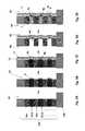
- FIGS. 4A-4Eillustrate a method of making a NAND string according to a first embodiment of the invention.
- a stack 120 of alternating layers 19 ( 19 a , 19 b etc.) and 121 ( 121 a , 121 b , etc.)are formed over the major surface of the substrate 100 .
- Layers 19 , 121may be deposited over the substrate by any suitable deposition method, such as sputtering, CVD, PECVD, MBE, etc.
- the layers 19 , 121may be 6 to 100 nm thick.
- the first layers 19comprise an electrically insulating material. Any suitable insulating material may be used, such as silicon oxide, silicon nitride, silicon oxynitride, a high-k dielectric (e.g., aluminum oxide, hafnium oxide, etc. or an organic insulating material).
- the second layers 121comprise a sacrificial material, such a semiconductor material.
- layers 121may comprise silicon, such as amorphous silicon or polysilicon, or another semiconductor material, such as a group IV semiconductor, including silicon-germanium and germanium.
- layers 121comprise intrinsic or undoped (if the as-deposited material inherently has a low p-type or n-type conductivity) semiconductor material, such as intrinsic or undoped polysilicon or amorphous silicon.
- p-type or n-type doped semiconductor materialssuch as lightly or heavily doped materials may also be used if desired.
- heavily dopedincludes semiconductor materials doped n-type or p-type to a concentration of above 10 18 cm ⁇ 3 .
- lightly doped semiconductor materialshave a doping concentration below 10 18 cm ⁇ 3 and intrinsic semiconductor materials have a doping concentration below 10 15 cm ⁇ 3 .
- the deposition of layers 19 , 121is followed by etching the stack 120 to form at least one a front side opening 81 in the stack 120 .
- An array of a front side openings 81(e.g., memory holes) may be formed in locations where vertical channels of NAND strings will be subsequently formed.
- the openings 81may be formed by photolithography and etching.
- the second material 121is selectively etched compared to the first material 19 to form front side recesses 62 in the second material 121 (i.e., layers 121 a , 121 b , etc).
- the recesses 62may be formed by selective, isotropic wet or dry etching which selectively etches the second material 121 compared to the first material 19 .
- the depth of each recess 62may be 3 to 20 nm. As will be described below, this step may be omitted if desired.
- a plurality of discrete semiconductor, metal or silicide charge storage regions 9are selectively formed on portions of the second material layers 121 exposed in the front side opening 81 .
- the charge storage regions 9comprise a plurality of charge storage segments or regions (e.g., 9 a and 9 b ) located on the exposed edges of the second material 121 in the front side recesses 62 .
- the charge storage regions 9are selectively formed by selective growth of the regions on the exposed edges of the semiconductor second material layers 121 but not on the exposed insulating first material layers 19 . Any suitable selective growth methods may be used to form the charge storage regions 9 , such as chemical vapor deposition.
- charge storage regions 9comprise doped polysilicon regions which are selectively grown by CVD on the portions of the undoped or intrinsic second material layers 121 (e.g., undoped or intrinsic semiconductor having a polycrystalline or amorphous structure, such as polysilicon, amorphous silicon, silicon germanium or germanium) exposed in the front side opening 81 .
- the doped polysilicon regions 9may comprise boron doped, p-type polysilicon regions (e.g., lightly or heavily doped) which are selectively, epitaxially grown on polysilicon layer 121 edges exposed in the front side openings 81 .
- the doped polysilicon regions 9are not grown on portions of the first material layers 19 (e.g., silicon oxide) exposed in the front side opening 81 .
- any suitable silicon selective epitaxial growth (SEG) conditionsmay be used to form regions 9 .
- a chemical vapor deposition (CVD) SEG processwhich combines a silicon source gas and a silicon growth inhibitor gas which inhibits silicon growth on the oxide layers 19 may be used.
- Exemplary silicon source gasesinclude silane and chloro-silanes (e.g., SiH 4 , SiH 2 Cl 2 , and/or SiHCl 3 ).
- Exemplary inhibitor gases which inhibit silicon growth on SiO 2include HCl and/or Cl 2 .
- H 2may be used as a carrier gas while B 2 H 6 , AsH 3 and/or PH 3 gases may be added to introduce dopants to the silicon regions 9 .
- Any suitable SEG temperatures and pressuresmay be used, such as a temperature of 500 to 800 C and a pressure of 10 mTorr to 100 Torr (i.e., LPCVD). Similar process conditions may be used to form germanium or silicon-germanium charge storage regions 9 , where germane (GeH 4 ) is substituted for silane or provided in addition to silane, at lower temperatures (e.g., 340 to 380 C) and pressure of about 10 mTorr-5 Torr, such as about 1 Torr.
- germane (GeH 4 )is substituted for silane or provided in addition to silane, at lower temperatures (e.g., 340 to 380 C) and pressure of about 10 mTorr-5 Torr, such as about 1 Torr.
- a thin silicide forming metal layersuch as titanium, cobalt or nickel is formed by any suitable method, such as ALD or sputtering, over the polysilicon floating gates 9 a , 9 b shown in FIG. 4C .
- the floating gates 9 a , 9 bare converted to a metal silicide (e.g., titanium, cobalt, nickel, etc. silicide) by the reaction of the metal and the polysilicon. Unreacted portions of the metal layer which remain over portions of insulating material 19 are then selectively etched.
- charge storage regions 9comprise selectively grown metal or silicide charge storage regions, such as on the portions of the second material layers exposed in the front side opening. Any metal (i.e., pure metal or conductive metal alloy) or metal silicide which may be selectively grown on exposed semiconductor layer 121 in the opening 81 may be used.
- the charge storage regions 9may comprise selectively grown tungsten, molybdenum or tantalum regions that are selectively grown on the semiconductor material (e.g., silicon) 121 but not on insulating material (e.g., silicon oxide) 19 from a metal halide source gas (e.g., tungsten hexafluoride) in a CVD process.
- a metal halide source gase.g., tungsten hexafluoride
- Selective deposition of refractory metals, such as W, Mo or Ta, on siliconmay be performed by metal halide source gas reduction by SiH 4 , where a ratio of SiH 4 to metal halide is less than one.
- the metal halide source gasmay comprise WF 6 , MoF 6 or TaCl 5 and the deposition temperature and pressure may range from 370 to 550 C and 100 to 500 mTorr, respectively.
- the ratio of the SiH 4 /metal halide flow ratesmay range between 0.4 and 0.6.
- the regions 9may be selectively grown in the front side recesses 62 until their edges are about even with the edges of the insulating material 19 such that they form a relatively straight sidewall of the front side opening 81 (e.g., as much as a timed selective growth permits).
- the selective growth of regions 9is terminated before regions 9 completely fill the recesses 62 .
- regions 9may partially fill recesses 62 and may remain horizontally recessed in the opening 81 compared to insulating material layers 19 .
- the selective growth of regions 9is terminated after regions 9 completely fill the recesses 62 such that the regions 9 protrude horizontally into the front side opening 81 past layers 19 , as shown in FIG. 5C .
- the regions 9are selectively formed by doping of the semiconductor layers 121 exposed in the front side opening 81 .
- a timed gas phase diffusion dopingmay be carried out to doped the edge portions 9 of layers 121 facing the opening 81 by providing a doping gas through the opening 81 .
- the dopingis terminated before the entire volume of layers 121 are doped, such that portions of layers 121 located behind regions 9 and facing away from the opening 81 remain undoped.
- the doping gasmay comprise a boron containing gas, such as diborane, to form p-type doped regions 9 , or a phosphorus or arsenic containing gas, such as phosphine or arsene, to form n-type doped regions 9 .
- a boron containing gassuch as diborane
- a phosphorus or arsenic containing gassuch as phosphine or arsene
- a tunnel dielectric layer 11is deposited over the charge storage regions 9 a , 9 b and the insulating first material layers 19 between the charge storage regions in the front side opening 81 .
- the channel 1is formed by depositing channel material 1 , such as a lightly doped or intrinsic polysilicon over the tunnel dielectric layer 11 in the front side opening 81 . If desired, a high temperature anneal may be performed after forming the channel.
- the entire opening 81may be filled to form the device illustrated in FIGS. 2A and 2B .
- a layer of channel materialmay first be deposited in the opening 81 followed by deposition of an insulating fill material 2 to form the device illustrated in FIGS. 1A and 1B .
- the channel 1may be U-shaped as illustrated in FIG. 3 .
- the channel 1may be formed by filling the front side opening 81 with a lightly doped semiconductor material (e.g., polysilicon) and then etched back from the top to form the pillar shaped (or U-shaped) channel 1 in the opening 81 .
- a lightly doped semiconductor materiale.g., polysilicon
- the space between the wings of the U-channel 1is filled with a gap fill insulating layer 103 , such as silicon oxide or another material.
- Layer 103may be formed by etching the stack 120 to form a rail shaped cut, followed by depositing an oxide layer followed by etch back or chemical mechanical polishing to form a planar top surface exposing the top surfaces of the channels 1 .
- the channelsare then connected to source and drain electrodes 102 , 202 as shown in FIGS. 1-3 , the select gate electrodes (not shown for clarity) are connected to select gate contacts and the control gate electrodes 3 are connected to word line contacts as known in the art.
- the stack 120is patterned to form one or more back side openings 84 in the stack.
- the back side opening(s) 84may be formed by photolithography and anisotropic etching of the stack.
- the opening(s) 84have a slit shape.
- layers 121are removed through the back side opening 84 to form back side recesses 64 between the first material layers 19 .
- layers 121may be removed completely by selective wet etching using a liquid etching medium which selectively etches the material of layers 121 compared to the materials of layers 19 and regions 9 .
- layers 121comprise undoped or intrinsic polysilicon
- layers 19comprise silicon oxide and regions 9 comprise doped polysilicon, silicide or metal
- an undoped polysilicon selective etchmay be used which stops on doped polysilicon (e.g., p-type polysilicon) regions 9 which act as an etch stop.
- the selective etchmay be a timed etch which is timed to remove only a portion of the sacrificial second material layers 121 through the back side opening 84 . In this case, a remaining portion of the second material layers 121 rather than regions 9 remain exposed in the back side recesses 64 .
- the blocking dielectric layer 7(also known as an inter-poly dielectric, IPD) is then formed in the back side recesses 64 through the back side opening 84 such that the blocking dielectric coats the sides of the back side recesses 64 and the back side of layers 19 exposed in the back side opening 84 .
- the blocking dielectric layer 7may comprise a silicon oxide layer deposited by conformal atomic layer deposition (ALD) or chemical vapor deposition (CVD).
- ALDconformal atomic layer deposition
- CVDchemical vapor deposition
- Other high-k dielectric materialssuch as hafnium oxide, or multi-layer dielectrics (e.g., ONO) may be used instead or in addition to silicon oxide.
- an insulating capping layere.g., silicon nitride
- the blocking dielectric 7may have a thickness of 6 to 20 nm.
- An optional anneal, such as a rapid thermal anneal,may be conducted after the blocking dielectric formation.
- the blocking dielectric layer 7comprises a plurality of clam-shaped blocking dielectric segments 7 a , 7 b in the back side recesses 64 connected to each other by vertical portions 7 c of the blocking dielectric layer 7 located on the exposed edges of the first material layers 19 in the back side opening 84 .
- a “clam” shapeis a side cross sectional shape configured similar to an English letter “C”.
- a clam shapehas two segments which extend substantially parallel to each other and to the major surface 100 a of the substrate 100 . The two segments are connected to each other by a third segment which extends substantially perpendicular to the first two segments and the surface 100 a .
- Each of the three segmentsmay have a straight shape (e.g., a rectangle side cross sectional shape) or a somewhat curved shape (e.g., rising and falling with the curvature of the underlying topography).
- substantially parallelincludes exactly parallel segments as well as segments which deviate by 20 degrees or less from the exact parallel configuration.
- substantially perpendicularincludes exactly perpendicular segments as well as segments which deviate by 20 degrees or less from the exact perpendicular configuration.
- the clam shapepreferably contains an opening bounded by the three segments and having a fourth side open.
- control gate 3 materialmay comprise a metal, such as tungsten or a heavily doped semiconductor, such as polysilicon.
- the control gate materialmay be deposited by CVD and fills the remaining volume of the back side recesses 64 inside the clam shaped blocking dielectric 7 segments and the entire back side opening 84 .
- the deposition of the control gate materialis followed by etching the control gate material to remove it from the back side opening 84 using anisotropic etching, while leaving the control gate material inside the back side recesses 64 in the clam shaped blocking dielectric 7 segments.
- the remaining control gate material inside the back side recesses 64forms the control gates 3 of the vertical NAND string.
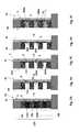
- FIGS. 5A-5Eillustrate a method of making a vertical NAND string according to another embodiment.
- the steps resulting in the structure shown in FIG. 5Aare the same as described above with respect to FIG. 4A .
- the front side recesses 62 shown in FIG. 4Bare omitted.
- the charge storage regions 9are selectively grown on exposed edges of the sacrificial layers 121 exposed in the front side opening 81 .
- the charge storage regions 9protrude horizontally (i.e., parallel to the major surface 100 a of the substrate 100 ) into the front side opening 81 .
- the processthen proceeds in the same manner as described above with respect to FIGS. 4C-4E .
- the tunnel dielectric layer 11 and the channel 1are formed in the front side opening 81 , as shown in FIG. 5C .
- the sacrificial layers 121are at least partially removed through the back side opening 84 , as shown in FIG. 5D .
- the blocking dielectric 7 and the control gates 3are formed through the back side opening as shown in FIG. 5E .
- the tunnel dielectric 11 of this embodimenthas a curved rather than a straight sidewall.
- FIGS. 6A-6Eillustrate a method of making a vertical NAND string according to another embodiment using a back side silicide charge storage region 9 formation.
- the steps resulting in the structure shown in FIG. 6Aare the same as described above with respect to FIG. 4A-4C or 5 A- 5 C.
- the initial process stepsmay be the same as the steps shown in FIGS. 4A-4C or 5 A- 5 C and described above, to form either recessed or protruding semiconductor charge storage regions 9 , tunnel dielectric 11 and channel 1 in the front side opening 81 .
- FIG. 6Aillustrates an in-process device at the same stage as either FIG. 4C or 5 C.
- the back side opening 84 and the back side recesses 64are formed, using steps similar to those described above with respect to FIG. 4D or 5 D.
- the entire sacrificial material layers 121are removed to expose the silicon (e.g., doped polysilicon) charge storage regions 9 in the back side recesses 64 , as shown in FIG. 6B .
- a metal layer 610is formed through the back side opening 84 in the back side recesses 64 , such that portions 610 a of the metal layer 610 are in contact with the polysilicon charge storage regions 9 , as shown in FIG. 6C .
- the metal layer 610may be formed using CVD or other deposition methods.
- the metal layer 610may comprise any metal layer which may form a silicide when it reacts with silicon.
- the metal layermay comprise tungsten, molybdenum, tantalum, titanium, nickel, cobalt, etc.
- the structureis annealed using any suitable silicidation anneal parameters to react portions 610 a of the metal layer 610 with the silicon charge storage regions 9 to convert the silicon (e.g., polysilicon) charge storage regions to silicide charge storage regions 609 (e.g., 609 a , 609 b , etc.).
- the silicide charge storage regionsmay comprise tungsten silicide, molybdenum silicide, tantalum silicide, titanium silicide, nickel silicide, cobalt silicide, etc.
- the entire silicon charge storage regions 9are converted to silicide charge storage regions 609 so that no unreacted silicon remains in the charge storage regions.
- only part of the silicon charge storage regionsare converted to silicide charge storage regions 609 , such that the charge storage regions comprise inner silicide portions adjacent to the blocking dielectric 7 and outer silicon portions adjacent to the tunnel dielectric 11 .
- the remaining unreacted portions 610 b of the metal layer 610are removed by any suitable selective wet etching without removing the silicide charge storage regions 609 , as is typical in a silicide formation process.
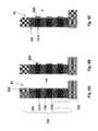
- FIGS. 7A-7Eillustrate a method of making a vertical NAND string according to an alternative embodiment using a back side silicide formation.
- portions 721 of the sacrificial semiconductor layers 121such as polysilicon or amorphous silicon layer portions 721 , remain in the back side recesses 64 .
- the charge storage regions 9may comprise semiconductor, metal or silicide regions in this embodiment.
- FIG. 7AThe steps resulting in the structure shown in FIG. 7A are the same as described above with respect to FIG. 4A-4C or 5 A- 5 C or 6 A. Then, as shown in FIG. 6B , the back side opening 84 and the back side recesses 64 are formed, using steps similar to those described above with respect to FIG. 4D or 5 D. Only parts of the entire sacrificial semiconductor material layers 121 are removed to leave portions 721 of the sacrificial semiconductor layers 121 exposed in the back side recesses 64 , as shown in FIG. 7B .
- a metal layer 610is formed through the back side opening 84 in the back side recesses 64 , such that portions 610 a of the metal layer 610 are in contact with the remaining portions 721 of the sacrificial semiconductor layers.
- the structureis annealed using any suitable silicidation anneal parameters to react portions 610 a of the metal layer 610 with the portions 721 of the sacrificial semiconductor layers to convert the portions 721 of the sacrificial semiconductor layers to silicide storage regions 609 (e.g., 609 a , 609 b ).
- the silicon charge storage regions 9may also converted to silicide charge storage regions 609 together with portions 721 so that no unreacted silicon remains in the charge storage regions, similar to the structure shown in FIG. 6D .
- FIGS. 8A-8Billustrate a method of making a vertical NAND string according to an alternative embodiment using a front side silicide formation.
- the steps resulting in the structure shown in FIG. 8Aare the same as described above with respect to FIGS. 4A-4C or 5 A- 5 C or 6 A, except for the deposition of the metal layer 810 .
- the stack 120is formed and then patterned to form the front side opening 81 .
- the charge storage regions 9may be omitted if the sacrificial layers 121 comprise silicon (e.g., doped or undoped polysilicon or amorphous silicon), as shown in FIG. 8A .
- silicon (e.g., doped polysilicon) charge storage regions 9may be selectively formed on the sacrificial layers 121 in the front side recesses 62 , as shown in FIG. 4C , or protruding into the front side opening 81 , as shown in FIG. 5C .
- a silicide forming metal layer 810is formed in the front side opening 81 .
- Layer 810may comprise the same material as that described for layer 610 above.
- the metal layer 810contacts the edges of the silicon sacrificial layers 121 if the charge storage regions 9 are not present or the metal layer 810 contacts the charge storage regions 9 if these regions are present in the front side opening 81 .
- the structureis then subjected to a silicidation anneal to react the metal layer 810 with the silicon regions exposed in the front side opening 81 , as shown in FIG. 8B .
- a silicidation annealto react the metal layer 810 with the silicon regions exposed in the front side opening 81 , as shown in FIG. 8B .
- the metal layer 810is reacted with the edge portions of the second (sacrificial silicon) material layers 121 exposed in the front side opening 81 to selectively form discrete silicide charge storage regions 809 .
- the metal layer 810is reacted with the silicon charge storage regions 9 exposed in the front side opening 81 to convert all or parts of the silicon charge storage regions 9 to discrete silicide charge storage regions 809 . If only the front parts of the silicon charge storage regions 9 are converted to silicide regions 809 , then composite charge storage regions are formed.
- the composite charge storage regionscomprise outer silicide portions 809 adjacent to the tunnel dielectric 11 and inner silicon portions 9 adjacent to the blocking dielectric 7 , as shown in FIG. 8C .
- the remaining unreacted portions of the metal layer 810are removed by any suitable selective wet etching without removing the discrete silicide charge storage regions 809 , as is typical in a silicide formation process.
- the processthen proceeds in the same manner as described above with respect to FIGS. 4D-4E or 5 D- 5 E, where the sacrificial layers 121 are removed through the back side opening 84 and then the blocking dielectric 7 and the control gates 3 are formed through the back side opening 84 .
- the plurality of discrete semiconductor, metal or silicide charge storage regions 9 , 609 , 809are nitrided to form nitrided charge storage regions.
- any of the charge storage regions described above and shown in FIG. 4 , 5 , 6 , 7 or 8may be annealed in a nitrogen containing ambient, such nitrogen or NO radical ambient at an elevated temperature, to convert at least a portion of the charge storage region to a nitride material.
- the edge or outer portion of the charge storage regions exposed in the front side opening 81may be converted to a nitride material prior to forming the tunnel dielectric layer 11 , while the inner portion of the charge storage regions facing the blocking dielectric 7 may remain a semiconductor, metal or silicide material that is not nitrided. This results in a composite charge storage region.
- the entire volume of the charge storage materialmay be nitrided to convert the entire charge storage material to a nitride material.
- the nitridationforms a silicon nitride charge storage region.
- the charge storage regions 9comprise a metal (e.g., tungsten, tantalum, titanium, etc.)
- the nitridationforms a metal nitride (e.g., tungsten nitride, tantalum nitride, titanium nitride, etc.) charge storage region.
- the plurality of vertically spaced apart charge storage regions 9 in this embodimentcomprise a nitrided metal.
- FIGS. 9A-9Eillustrate a method of making a vertical NAND string with a hybrid charge storage structure according to an alternative embodiment.
- a silicon nitride charge storage layer 909is provided in the front side opening 81 in contact with the plurality of discrete semiconductor, metal or silicide charge storage regions 9 , 609 , 809 described above to form a hybrid charge storage structure. Any of the charge storage regions described above and shown in FIG. 4 , 5 , 6 , 7 or 8 may be combined with the silicon nitride charge storage layer 909 to form the hybrid charge storage structure.
- FIGS. 9A and 9Bthe structure described above with respect to FIGS. 5A and 5B having the metal or semiconductor charge storage regions 9 protruding into the front side opening 81 is formed. Then, the silicon nitride layer 909 is formed in the front side opening 81 in contact with the charge storage regions 9 , as shown in FIG. 9C . While silicon nitride is a preferred material for layer 909 , other continuous dielectric (i.e., electrically insulating) materials, such as silicon oxynitride, may be used instead or in addition to silicon nitride. Thus, a continuous dielectric charge storage layer 909 is located in contact with the plurality of vertically spaced apart charge storage regions 9 .
- the processthen proceeds in the same manner as described above with respect to FIGS. 4D-4E or 5 D- 5 E where the sacrificial layers 121 are removed through the back side opening 84 and then the blocking dielectric 7 and the control gates 3 are formed through the back side opening 84 .
- at least a part of the charge storage regionsmay be converted to a silicide using the back side silicidation process described above with respect to FIGS. 6D-6E or 7 D- 7 E.
- at least a part of the metal or semiconductor charge storage regionsmay be converted to a silicide or a nitride using the front side silicidation process (as shown in FIGS. 8A-8C ) or front side nitridation process described above.
- FIG. 10is a side cross sectional view of a NAND string of another embodiment.
- each charge storage region 9is floating gate made of three layers or regions 91 , 92 , 93 .
- the first layer 91is polysilicon.
- the first layer 91may be doped or undoped (i.e., intrinsic).
- the second layer 92is preferably a silicide, such as tungsten silicide, molybdenum silicide, tantalum silicide, cobalt silicide, titanium silicide, nickel silicide or any other suitable silicide.
- the third layer 93is polysilicon.
- the third layer 93may be doped or undoped, similar to the first layer 91 .
- first and third layers 91 and 93need not be the same.
- the first layer 91may be a doped polysilicon layer while the third layer 93 may be an undoped polysilicon layer.
- the first layer 91may be an undoped polysilicon layer while the third layer 93 may be a doped polysilicon layer.
- a stack 120 of alternating layers 19 and 121may be deposited over the substrate 100 by any suitable method, such as sputtering, CVD, PECVD, MBE, etc as illustrated in FIG. 4A .
- the deposition of layers 19 , 121is followed by etching the stack 120 to form at least one a front side opening 81 in the stack 120 .
- the second material 121is selectively etched compared to the first material 19 to form front side recesses 62 in the second material 121 .
- the recesses 62may be formed by selective, isotropic wet or dry etching which selectively etches the second material 121 compared to the first material 19 .
- the second material 121is polysilicon. The remaining portion of the second material 121 forms the first layer 91 of three layer 91 , 92 , 93 charge storage region 9 illustrated in FIG. 10 .
- a metal layer 611is formed through the front side opening 81 such that portions 611 a of the metal layer 611 are in contact with the edge portions of the polysilicon charge storage region layers 91 / 121 exposed in the front side recesses 62 , as shown in FIG. 11A .
- the remaining portions 611 b of layer 611contact the exposed edges of layers 19 in opening 81 .
- the metal layer 611may be formed using CVD or other deposition methods.
- the metal layer 611may comprise any metal layer which may form a silicide when it reacts with silicon.
- the metal layermay comprise tungsten, molybdenum, tantalum, titanium, nickel, cobalt, etc.
- the structureis annealed using any suitable silicidation anneal parameters to react portions 611 a of the metal layer 611 with the silicon charge storage regions 91 to convert a portion of the silicon (e.g., polysilicon) charge storage regions 91 to silicide charge storage regions 92 .
- the silicide charge storage regions 92may comprise tungsten silicide, molybdenum silicide, tantalum silicide, titanium silicide, nickel silicide, cobalt silicide, etc.
- the remaining unreacted portions 611 b of the metal layer 611 located adjacent to the layers of first material 19are removed by any suitable selective wet etching method without removing the silicide charge storage regions 92 , as is typical in a silicide formation process.
- the rest of the recess 62is filled with the third layer 93 of material making up the charge storage regions 9 of the present embodiment.
- Layer 93comprises a polysilicon layer which may be deposited conformally on the silicide regions 92 through the opening 81 and followed by an anisotropic etch to remove portions of layer 93 exposed in the opening 81 . Portions of layer 93 formed in the recesses 62 remain after the anisotropic etch.
- the silicide layer 92forms discrete charge storage segment portions of the floating gates 9 which fill back portions of the front side recesses 62 and the polysilicon layer 93 fills front portions of the front side recesses 62 .
- the front side opening 81is then filled by forming the tunnel dielectric 11 and the channel 1 as described above.
- the tunnel dielectric 11has a straight sidewall facing the polysilicon layer 93 portions of the floating gates 9 because the edges of layers 93 and edge of layers 19 exposed in the front side opening 81 are substantially planar with each other (i.e., the edges of layers 93 and 19 form a substantially planar surface of the cylindrical opening 81 ).
- the tunnel dielectric 11is formed on the substantially planar surface which results in the straight sidewall of the tunnel dielectric.
- each of the plurality of discrete, vertically separated floating gates 9is located in a recess 62 between the insulating layers 19 , and the straight sidewall of the tunnel dielectric 11 layer contacts the discrete portion of the polysilicon layer 93 in each floating gate 9 .
- the stack 120is patterned to form one or more back side openings 84 in the stack.
- the back side opening(s) 84may be formed by photolithography and anisotropic etching of the stack.
- the opening(s) 84have a cut shape (e.g., a slit shape, such as a slit shaped trench). Then, a portion of the second material layers 91 / 121 are removed through the back side opening 84 to form back side recesses 64 between the first material layers 19 .
- portions of layers 91 / 121may be removed by a timed selective wet etching using a liquid etching medium which selectively etches the material of layers 91 / 121 compared to the materials of layers 19 .
- portions of the polysilicon layers 91 / 121 located in opening 81 outside (e.g., behind) the front side recesses 62are removed such that the polysilicon layer 93 , the silicide layer 92 and remaining portions of the polysilicon 91 / 121 layer remaining in the front side recesses 62 form discrete, vertically separated polysilicon-silicide-polysilicon floating gates 9 .
- Each of the plurality of discrete, vertically separated floating gates 9includes a discrete portion of the polysilicon layer 91 , a discrete portion of the polysilicon layer 93 and a discrete portion of the silicide layer 92 located between the discrete portions of the polysilicon layers 91 , 93 .
- the blocking dielectric layer 7(also known as an inter-poly dielectric, IPD) is then formed in the back side recesses 64 through the back side opening 84 such that the blocking dielectric coats the sides of the back side recesses 64 and the back side of layers 19 exposed in the back side opening 84 .
- the blocking dielectric 7coats the back side of the first layer 91 of the charge storage region (e.g., floating gate) 9 .
- the blocking dielectric layer 7may comprise a silicon oxide layer deposited by conformal atomic layer deposition (ALD) or chemical vapor deposition (CVD).
- high-k dielectric materialssuch as hafnium oxide, or multi-layer dielectrics (e.g., ONO) may be used instead or in addition to silicon oxide.
- an insulating capping layere.g., silicon nitride
- the blocking dielectric 7may have a thickness of 6 to 20 nm.
- An optional anneal, such as a rapid thermal anneal,may be conducted after the blocking dielectric formation.
- the blocking dielectric layer 7comprises a plurality of clam-shaped blocking dielectric segments 7 a , 7 b in the back side recesses 64 connected to each other by vertical portions 7 c of the blocking dielectric layer 7 located on the exposed edges of the first material layers 19 in the back side opening 84 .
- the blocking dielectric 7is formed through the back side opening 84 (e.g., the cut area) such that the blocking dielectric 7 contacts the sidewall of the charge storage material (e.g., layer 91 of the floating gate 9 ) exposed between the first material layers 19 .
- control gate 3 materialmay comprise a metal, such as tungsten, TiN and tungsten, or a heavily doped semiconductor, such as polysilicon.
- the control gate materialmay be deposited by CVD and fills the remaining volume of the back side recesses 64 inside the clam shaped blocking dielectric 7 segments and the entire back side opening 84 .
- the deposition of the control gate materialis followed by etching the control gate material to remove it from the back side opening 84 using anisotropic etching, while leaving the control gate material inside the back side recesses 64 in the clam shaped blocking dielectric 7 segments.
- the remaining control gate material inside the back side recesses 64forms the control gates 3 of the vertical NAND string.
- FIGS. 12A and 12Bare respectively side cut away cross sectional and top cross sectional views of a NAND string of one embodiment.
- the stackincludes three device level as indicated by the three control gates CG 0 , CG 1 , CG 2 .
- the three dimensional NAND string of the present embodimentis not limited to three device levels.
- the three dimensional NAND stringmay have 2-64 device levels, such as 2-32 device levels, such as 8-16 device levels.
- the NAND stringalso includes a source side select transistor and a drain side select transistor, containing the source side select gate SGS 301 and the drain gate select gate SGD 302 .
- the channel region 1contains doped source 303 and drain 304 regions at its opposite ends. The source and drain regions contact the respective electrodes shown in FIGS. 1A and 2A .
- an embodiment of a NAND stringmay include a three layer blocking dielectric 7 .
- the three layer blocking dielectric 7may include a first layer 71 comprising a nitride (e.g., silicon nitride), a second layer 72 comprising an oxide (e.g., silicon oxide), and a third layer 73 comprising another nitride (e.g., silicon nitride).
- the NAND stringincludes insulating fill material 2 as illustrated in FIG. 12B and discussed in regards to FIGS. 1A and 1B above.
- any suitable radial layer thicknessesmay be used, such as 3-20 nm, for example about 7 nm, for the channel 1 and tunnel dielectric 11 , 1-5 nm, such as about 2 nm for the fill material 2 , 3-15 nm, such as about 5 nm for the floating gate 9 , and 10-20 nm, such as about 11 nm for the blocking dielectric 7 (e.g., about 2 nm/6 nm/3 nm for the respective nitride/oxide/nitride layers).
- Layers 19may be 15-40 nm thick, such as about 25 nm thick in the vertical direction and the control gate layers 3 may be 20-50 nm thick, such as about 35 nm thick in the vertical direction.
- the three dimensional NAND string with a floating gate 9 made of three layers 91 , 92 , 93has an excellent coupling ratio with a faster programming speed than a similar structure using a nitride trap charge storage layer.
- the NAND stringalso has the advantage of low cell to cell interference and low capacitive coupling between the adjacent cells. Additionally, the NAND string also has the advantage of low program noise and large program saturation due to its relatively large charge storage region and excellent blocking dielectric.
- the three dimensional NAND string of the present embodimentalso has the advantage of a small channel relative to a two dimensional NAND string while also having the advantage of using Fowler-Nordheim tunneling versus hot hole injection used in nitride trap devices.
- the three dimensional NAND string of the present embodimenthas both excellent short term data retention and long term data retention. Further, the inventors have discovered that the three dimensional NAND string of the present embodiment may store four or more bits of information per memory cell.
Landscapes
- Engineering & Computer Science (AREA)
- Physics & Mathematics (AREA)
- Condensed Matter Physics & Semiconductors (AREA)
- General Physics & Mathematics (AREA)
- Manufacturing & Machinery (AREA)
- Computer Hardware Design (AREA)
- Microelectronics & Electronic Packaging (AREA)
- Power Engineering (AREA)
- Semiconductor Memories (AREA)
- Non-Volatile Memory (AREA)
- Chemical & Material Sciences (AREA)
- Crystallography & Structural Chemistry (AREA)
Abstract
Description
Claims (11)
Priority Applications (3)
| Application Number | Priority Date | Filing Date | Title |
|---|---|---|---|
| US14/190,974US8928061B2 (en) | 2010-06-30 | 2014-02-26 | Three dimensional NAND device with silicide containing floating gates |
| US14/464,385US9159739B2 (en) | 2010-06-30 | 2014-08-20 | Floating gate ultrahigh density vertical NAND flash memory |
| US14/539,811US9165940B2 (en) | 2010-06-30 | 2014-11-12 | Three dimensional NAND device with silicide containing floating gates and method of making thereof |
Applications Claiming Priority (7)
| Application Number | Priority Date | Filing Date | Title |
|---|---|---|---|
| US12/827,761US8349681B2 (en) | 2010-06-30 | 2010-06-30 | Ultrahigh density monolithic, three dimensional vertical NAND memory device |
| US13/693,337US8461000B2 (en) | 2010-06-30 | 2012-12-04 | Method of making ultrahigh density vertical NAND memory device |
| US13/762,988US9397093B2 (en) | 2013-02-08 | 2013-02-08 | Three dimensional NAND device with semiconductor, metal or silicide floating gates and method of making thereof |
| US13/875,854US8580639B2 (en) | 2010-06-30 | 2013-05-02 | Method of making ultrahigh density vertical NAND memory device |
| US201361862912P | 2013-08-06 | 2013-08-06 | |
| US14/051,627US8765543B2 (en) | 2010-06-30 | 2013-10-11 | Method of making an ultrahigh density vertical NAND memory device with shielding wings |
| US14/190,974US8928061B2 (en) | 2010-06-30 | 2014-02-26 | Three dimensional NAND device with silicide containing floating gates |
Related Parent Applications (3)
| Application Number | Title | Priority Date | Filing Date |
|---|---|---|---|
| US13/762,988Continuation-In-PartUS9397093B2 (en) | 2010-06-30 | 2013-02-08 | Three dimensional NAND device with semiconductor, metal or silicide floating gates and method of making thereof |
| US14/051,627Continuation-In-PartUS8765543B2 (en) | 2010-06-30 | 2013-10-11 | Method of making an ultrahigh density vertical NAND memory device with shielding wings |
| US14/051,627ContinuationUS8765543B2 (en) | 2010-06-30 | 2013-10-11 | Method of making an ultrahigh density vertical NAND memory device with shielding wings |
Related Child Applications (2)
| Application Number | Title | Priority Date | Filing Date |
|---|---|---|---|
| US14/464,385Continuation-In-PartUS9159739B2 (en) | 2010-06-30 | 2014-08-20 | Floating gate ultrahigh density vertical NAND flash memory |
| US14/539,811DivisionUS9165940B2 (en) | 2010-06-30 | 2014-11-12 | Three dimensional NAND device with silicide containing floating gates and method of making thereof |
Publications (2)
| Publication Number | Publication Date |
|---|---|
| US20140175530A1 US20140175530A1 (en) | 2014-06-26 |
| US8928061B2true US8928061B2 (en) | 2015-01-06 |
Family
ID=50973672
Family Applications (2)
| Application Number | Title | Priority Date | Filing Date |
|---|---|---|---|
| US14/190,974ActiveUS8928061B2 (en) | 2010-06-30 | 2014-02-26 | Three dimensional NAND device with silicide containing floating gates |
| US14/539,811ActiveUS9165940B2 (en) | 2010-06-30 | 2014-11-12 | Three dimensional NAND device with silicide containing floating gates and method of making thereof |
Family Applications After (1)
| Application Number | Title | Priority Date | Filing Date |
|---|---|---|---|
| US14/539,811ActiveUS9165940B2 (en) | 2010-06-30 | 2014-11-12 | Three dimensional NAND device with silicide containing floating gates and method of making thereof |
Country Status (1)
| Country | Link |
|---|---|
| US (2) | US8928061B2 (en) |
Cited By (41)
| Publication number | Priority date | Publication date | Assignee | Title |
|---|---|---|---|---|
| US20140307508A1 (en)* | 2013-04-16 | 2014-10-16 | Mosaid Technologies Incorporated | U-Shaped Common-Body Type Cell String |
| US20160293617A1 (en)* | 2014-06-25 | 2016-10-06 | Sandisk Technologies Llc | Vertical floating gate nand with selectively deposited ald metal films |
| US9524977B2 (en) | 2015-04-15 | 2016-12-20 | Sandisk Technologies Llc | Metal-semiconductor alloy region for enhancing on current in a three-dimensional memory structure |
| US9576966B1 (en) | 2015-09-21 | 2017-02-21 | Sandisk Technologies Llc | Cobalt-containing conductive layers for control gate electrodes in a memory structure |
| US9627399B2 (en) | 2015-07-24 | 2017-04-18 | Sandisk Technologies Llc | Three-dimensional memory device with metal and silicide control gates |
| US9627403B2 (en) | 2015-04-30 | 2017-04-18 | Sandisk Technologies Llc | Multilevel memory stack structure employing support pillar structures |
| US9646975B2 (en) | 2015-09-21 | 2017-05-09 | Sandisk Technologies Llc | Lateral stack of cobalt and a cobalt-semiconductor alloy for control gate electrodes in a memory structure |
| US20170162589A1 (en)* | 2013-01-10 | 2017-06-08 | Micron Technology, Inc. | Transistors, Semiconductor Constructions, and Methods of Forming Semiconductor Constructions |
| US9768270B2 (en) | 2014-06-25 | 2017-09-19 | Sandisk Technologies Llc | Method of selectively depositing floating gate material in a memory device |
| US9780182B2 (en) | 2015-02-04 | 2017-10-03 | Sandisk Technologies Llc | Molybdenum-containing conductive layers for control gate electrodes in a memory structure |
| US9806089B2 (en) | 2015-09-21 | 2017-10-31 | Sandisk Technologies Llc | Method of making self-assembling floating gate electrodes for a three-dimensional memory device |
| US9842907B2 (en) | 2015-09-29 | 2017-12-12 | Sandisk Technologies Llc | Memory device containing cobalt silicide control gate electrodes and method of making thereof |
| US9881929B1 (en) | 2016-10-27 | 2018-01-30 | Sandisk Technologies Llc | Multi-tier memory stack structure containing non-overlapping support pillar structures and method of making thereof |
| US9941293B1 (en) | 2016-10-12 | 2018-04-10 | Sandisk Technologies Llc | Select transistors with tight threshold voltage in 3D memory |
| US9960180B1 (en) | 2017-03-27 | 2018-05-01 | Sandisk Technologies Llc | Three-dimensional memory device with partially discrete charge storage regions and method of making thereof |
| US9984963B2 (en) | 2015-02-04 | 2018-05-29 | Sandisk Technologies Llc | Cobalt-containing conductive layers for control gate electrodes in a memory structure |
| US9991277B1 (en) | 2016-11-28 | 2018-06-05 | Sandisk Technologies Llc | Three-dimensional memory device with discrete self-aligned charge storage elements and method of making thereof |
| US10020318B2 (en) | 2015-09-10 | 2018-07-10 | Samsung Electronics Co., Ltd. | Semiconductor device |
| US10056131B2 (en) | 2015-05-26 | 2018-08-21 | Semiconductor Energy Laboratory Co., Ltd. | Semiconductor memory device including first memory cell and second memory cell over first memory cell |
| US10128261B2 (en) | 2010-06-30 | 2018-11-13 | Sandisk Technologies Llc | Cobalt-containing conductive layers for control gate electrodes in a memory structure |
| US10276583B2 (en) | 2015-10-29 | 2019-04-30 | Sandisk Technologies Llc | Three-dimensional memory device containing composite word lines including a metal silicide and an elemental metal and method of making thereof |
| US10340393B2 (en) | 2013-01-07 | 2019-07-02 | Micron Technology, Inc. | Semiconductor constructions, methods of forming vertical memory strings, and methods of forming vertically-stacked structures |
| US10593693B2 (en) | 2017-06-16 | 2020-03-17 | Semiconductor Energy Laboratory Co., Ltd. | Semiconductor device and method for manufacturing semiconductor device |
| US10622368B2 (en) | 2015-06-24 | 2020-04-14 | Sandisk Technologies Llc | Three-dimensional memory device with semicircular metal-semiconductor alloy floating gate electrodes and methods of making thereof |
| US10665604B2 (en) | 2017-07-21 | 2020-05-26 | Semiconductor Energy Laboratory Co., Ltd. | Semiconductor device, semiconductor wafer, memory device, and electronic device |
| US10741572B2 (en) | 2015-02-04 | 2020-08-11 | Sandisk Technologies Llc | Three-dimensional memory device having multilayer word lines containing selectively grown cobalt or ruthenium and method of making the same |
| US20200388688A1 (en)* | 2018-12-17 | 2020-12-10 | Sandisk Technologies Llc | Three-dimensional memory device including a silicon-germanium source contact layer and method of making the same |
| US10872901B2 (en) | 2018-09-14 | 2020-12-22 | Samsung Electronics Co., Ltd. | Integrated circuit device and method of manufacturing the same |
| US11049946B2 (en) | 2015-08-31 | 2021-06-29 | Semiconductor Energy Laboratory Co., Ltd. | Semiconductor device |
| US20210233895A1 (en)* | 2020-01-23 | 2021-07-29 | Kioxia Corporation | Semiconductor storage device |
| US11114470B2 (en) | 2017-06-02 | 2021-09-07 | Semiconductor Energy Laboratory Co., Ltd. | Semiconductor device, electronic component, and electronic device |
| US11152366B2 (en) | 2017-06-08 | 2021-10-19 | Semiconductor Energy Laboratory Co., Ltd. | Semiconductor device and method for driving semiconductor device |
| US20220130852A1 (en)* | 2020-10-27 | 2022-04-28 | Sandisk Technologies Llc | Multi-tier three-dimensional memory device with nested contact via structures and methods for forming the same |
| US20220139951A1 (en)* | 2020-11-02 | 2022-05-05 | Samsung Electronics Co., Ltd. | Semiconductor device and massive data storage system including the same |
| US20220165746A1 (en)* | 2020-11-24 | 2022-05-26 | Macronix International Co., Ltd. | Semiconductor device and method for fabricating the same |
| US11545503B2 (en)* | 2013-09-02 | 2023-01-03 | Samsung Electronics Co., Ltd. | Semiconductor device, systems and methods of manufacture |
| US11631695B2 (en) | 2020-10-30 | 2023-04-18 | Sandisk Technologies Llc | Three-dimensional memory device containing composite word lines containing metal and silicide and method of making thereof |
| US11682667B2 (en) | 2017-06-27 | 2023-06-20 | Semiconductor Energy Laboratory Co., Ltd. | Memory cell including cell transistor including control gate and charge accumulation layer |
| US12010840B2 (en)* | 2019-12-26 | 2024-06-11 | Samsung Electronics Co., Ltd. | Vertical type non-volatile memory device and method of manufacturing the same |
| US12176203B2 (en) | 2022-01-11 | 2024-12-24 | Sandisk Technologies Llc | Methods and apparatuses for forming semiconductor devices containing tungsten layers using a tungsten growth suppressant |
| US12217965B2 (en) | 2022-01-11 | 2025-02-04 | Sandisk Technologies Llc | Methods and apparatuses for forming semiconductor devices containing tungsten layers using a tungsten growth suppressant |
Families Citing this family (99)
| Publication number | Priority date | Publication date | Assignee | Title |
|---|---|---|---|---|
| US8349681B2 (en) | 2010-06-30 | 2013-01-08 | Sandisk Technologies Inc. | Ultrahigh density monolithic, three dimensional vertical NAND memory device |
| US8928061B2 (en) | 2010-06-30 | 2015-01-06 | SanDisk Technologies, Inc. | Three dimensional NAND device with silicide containing floating gates |
| US9159739B2 (en) | 2010-06-30 | 2015-10-13 | Sandisk Technologies Inc. | Floating gate ultrahigh density vertical NAND flash memory |
| US9312257B2 (en) | 2012-02-29 | 2016-04-12 | Semiconductor Energy Laboratory Co., Ltd. | Semiconductor device |
| US8878278B2 (en) | 2012-03-21 | 2014-11-04 | Sandisk Technologies Inc. | Compact three dimensional vertical NAND and method of making thereof |
| US9132436B2 (en) | 2012-09-21 | 2015-09-15 | Applied Materials, Inc. | Chemical control features in wafer process equipment |
| US10256079B2 (en) | 2013-02-08 | 2019-04-09 | Applied Materials, Inc. | Semiconductor processing systems having multiple plasma configurations |
| JP2017010951A (en) | 2014-01-10 | 2017-01-12 | 株式会社東芝 | Semiconductor memory and its manufacturing method |
| US9224747B2 (en) | 2014-03-26 | 2015-12-29 | Sandisk Technologies Inc. | Vertical NAND device with shared word line steps |
| US9553146B2 (en) | 2014-06-05 | 2017-01-24 | Sandisk Technologies Llc | Three dimensional NAND device having a wavy charge storage layer |
| US9230983B1 (en) | 2014-08-20 | 2016-01-05 | Sandisk Technologies Inc. | Metal word lines for three dimensional memory devices |
| US20160064406A1 (en)* | 2014-09-02 | 2016-03-03 | Kabushiki Kaisha Toshiba | Semiconductor memory device and method for manufacturing the same |
| CN104269406B (en)* | 2014-09-16 | 2017-04-19 | 华中科技大学 | Core shell type nanowire three-dimensional NAND flash memory device and manufacturing method thereof |
| US9966240B2 (en) | 2014-10-14 | 2018-05-08 | Applied Materials, Inc. | Systems and methods for internal surface conditioning assessment in plasma processing equipment |
| US9355922B2 (en) | 2014-10-14 | 2016-05-31 | Applied Materials, Inc. | Systems and methods for internal surface conditioning in plasma processing equipment |
| US9570455B2 (en) | 2014-11-25 | 2017-02-14 | Sandisk Technologies Llc | Metal word lines for three dimensional memory devices |
| US9698223B2 (en) | 2014-11-25 | 2017-07-04 | Sandisk Technologies Llc | Memory device containing stress-tunable control gate electrodes |
| US9496419B2 (en) | 2014-11-25 | 2016-11-15 | Sandisk Technologies Llc | Ruthenium nucleation layer for control gate electrodes in a memory structure |
| US11637002B2 (en) | 2014-11-26 | 2023-04-25 | Applied Materials, Inc. | Methods and systems to enhance process uniformity |
| US10573496B2 (en) | 2014-12-09 | 2020-02-25 | Applied Materials, Inc. | Direct outlet toroidal plasma source |
| US20160225652A1 (en) | 2015-02-03 | 2016-08-04 | Applied Materials, Inc. | Low temperature chuck for plasma processing systems |
| US9728437B2 (en) | 2015-02-03 | 2017-08-08 | Applied Materials, Inc. | High temperature chuck for plasma processing systems |
| US9356034B1 (en) | 2015-02-05 | 2016-05-31 | Sandisk Technologies Inc. | Multilevel interconnect structure and methods of manufacturing the same |
| CN107548520B (en)* | 2015-02-24 | 2021-05-25 | 东芝存储器株式会社 | Semiconductor memory device and method of manufacturing the same |
| WO2016139725A1 (en)* | 2015-03-02 | 2016-09-09 | 株式会社 東芝 | Semiconductor memory device and method for producing same |
| US9691645B2 (en) | 2015-08-06 | 2017-06-27 | Applied Materials, Inc. | Bolted wafer chuck thermal management systems and methods for wafer processing systems |
| US9741593B2 (en) | 2015-08-06 | 2017-08-22 | Applied Materials, Inc. | Thermal management systems and methods for wafer processing systems |
| US9349605B1 (en) | 2015-08-07 | 2016-05-24 | Applied Materials, Inc. | Oxide etch selectivity systems and methods |
| US10504700B2 (en) | 2015-08-27 | 2019-12-10 | Applied Materials, Inc. | Plasma etching systems and methods with secondary plasma injection |
| US10020317B2 (en)* | 2015-08-31 | 2018-07-10 | Cypress Semiconductor Corporation | Memory device with multi-layer channel and charge trapping layer |
| KR102422087B1 (en) | 2015-09-23 | 2022-07-18 | 삼성전자주식회사 | Vertical memory devices and methods of manufacturing the same |
| US9911748B2 (en)* | 2015-09-28 | 2018-03-06 | Sandisk Technologies Llc | Epitaxial source region for uniform threshold voltage of vertical transistors in 3D memory devices |
| US9831125B2 (en)* | 2015-12-14 | 2017-11-28 | Toshiba Memory Corporation | Method for manufacturing semiconductor device |
| US9673213B1 (en) | 2016-02-15 | 2017-06-06 | Sandisk Technologies Llc | Three dimensional memory device with peripheral devices under dummy dielectric layer stack and method of making thereof |
| US9595535B1 (en) | 2016-02-18 | 2017-03-14 | Sandisk Technologies Llc | Integration of word line switches with word line contact via structures |
| JP6613177B2 (en)* | 2016-03-11 | 2019-11-27 | キオクシア株式会社 | Nonvolatile semiconductor memory device and manufacturing method thereof |
| US9812463B2 (en)* | 2016-03-25 | 2017-11-07 | Sandisk Technologies Llc | Three-dimensional memory device containing vertically isolated charge storage regions and method of making thereof |
| US9711530B1 (en) | 2016-03-25 | 2017-07-18 | Sandisk Technologies Llc | Locally-trap-characteristic-enhanced charge trap layer for three-dimensional memory structures |
| US10522371B2 (en) | 2016-05-19 | 2019-12-31 | Applied Materials, Inc. | Systems and methods for improved semiconductor etching and component protection |
| US10504754B2 (en) | 2016-05-19 | 2019-12-10 | Applied Materials, Inc. | Systems and methods for improved semiconductor etching and component protection |
| US9865484B1 (en) | 2016-06-29 | 2018-01-09 | Applied Materials, Inc. | Selective etch using material modification and RF pulsing |
| US10629473B2 (en) | 2016-09-09 | 2020-04-21 | Applied Materials, Inc. | Footing removal for nitride spacer |
| US10546729B2 (en) | 2016-10-04 | 2020-01-28 | Applied Materials, Inc. | Dual-channel showerhead with improved profile |
| US9934942B1 (en) | 2016-10-04 | 2018-04-03 | Applied Materials, Inc. | Chamber with flow-through source |
| US10163696B2 (en) | 2016-11-11 | 2018-12-25 | Applied Materials, Inc. | Selective cobalt removal for bottom up gapfill |
| US10026621B2 (en) | 2016-11-14 | 2018-07-17 | Applied Materials, Inc. | SiN spacer profile patterning |
| US10431429B2 (en) | 2017-02-03 | 2019-10-01 | Applied Materials, Inc. | Systems and methods for radial and azimuthal control of plasma uniformity |
| US10319739B2 (en) | 2017-02-08 | 2019-06-11 | Applied Materials, Inc. | Accommodating imperfectly aligned memory holes |
| US10943834B2 (en) | 2017-03-13 | 2021-03-09 | Applied Materials, Inc. | Replacement contact process |
| JP7176860B6 (en) | 2017-05-17 | 2022-12-16 | アプライド マテリアルズ インコーポレイテッド | Semiconductor processing chamber to improve precursor flow |
| US11276559B2 (en) | 2017-05-17 | 2022-03-15 | Applied Materials, Inc. | Semiconductor processing chamber for multiple precursor flow |
| US11276590B2 (en) | 2017-05-17 | 2022-03-15 | Applied Materials, Inc. | Multi-zone semiconductor substrate supports |
| US10497579B2 (en) | 2017-05-31 | 2019-12-03 | Applied Materials, Inc. | Water-free etching methods |
| US10920320B2 (en) | 2017-06-16 | 2021-02-16 | Applied Materials, Inc. | Plasma health determination in semiconductor substrate processing reactors |
| US10510840B2 (en)* | 2017-06-20 | 2019-12-17 | Taiwan Semiconductor Manufacturing Co., Ltd. | GAA FET with u-shaped channel |
| US10541246B2 (en)* | 2017-06-26 | 2020-01-21 | Applied Materials, Inc. | 3D flash memory cells which discourage cross-cell electrical tunneling |
| US10727080B2 (en) | 2017-07-07 | 2020-07-28 | Applied Materials, Inc. | Tantalum-containing material removal |
| US10446681B2 (en)* | 2017-07-10 | 2019-10-15 | Micron Technology, Inc. | NAND memory arrays, and devices comprising semiconductor channel material and nitrogen |
| US10541184B2 (en) | 2017-07-11 | 2020-01-21 | Applied Materials, Inc. | Optical emission spectroscopic techniques for monitoring etching |
| US10043674B1 (en) | 2017-08-04 | 2018-08-07 | Applied Materials, Inc. | Germanium etching systems and methods |
| US10297458B2 (en) | 2017-08-07 | 2019-05-21 | Applied Materials, Inc. | Process window widening using coated parts in plasma etch processes |
| US10453798B2 (en) | 2017-09-27 | 2019-10-22 | Sandisk Technologies Llc | Three-dimensional memory device with gated contact via structures and method of making thereof |
| US10903054B2 (en) | 2017-12-19 | 2021-01-26 | Applied Materials, Inc. | Multi-zone gas distribution systems and methods |
| US11328909B2 (en) | 2017-12-22 | 2022-05-10 | Applied Materials, Inc. | Chamber conditioning and removal processes |
| US10297611B1 (en)* | 2017-12-27 | 2019-05-21 | Micron Technology, Inc. | Transistors and arrays of elevationally-extending strings of memory cells |
| US10559466B2 (en) | 2017-12-27 | 2020-02-11 | Micron Technology, Inc. | Methods of forming a channel region of a transistor and methods used in forming a memory array |
| US10854426B2 (en) | 2018-01-08 | 2020-12-01 | Applied Materials, Inc. | Metal recess for semiconductor structures |
| US10679870B2 (en) | 2018-02-15 | 2020-06-09 | Applied Materials, Inc. | Semiconductor processing chamber multistage mixing apparatus |
| US10964512B2 (en) | 2018-02-15 | 2021-03-30 | Applied Materials, Inc. | Semiconductor processing chamber multistage mixing apparatus and methods |
| TWI766433B (en) | 2018-02-28 | 2022-06-01 | 美商應用材料股份有限公司 | Systems and methods to form airgaps |
| US10593560B2 (en) | 2018-03-01 | 2020-03-17 | Applied Materials, Inc. | Magnetic induction plasma source for semiconductor processes and equipment |
| US10319600B1 (en) | 2018-03-12 | 2019-06-11 | Applied Materials, Inc. | Thermal silicon etch |
| US10497573B2 (en) | 2018-03-13 | 2019-12-03 | Applied Materials, Inc. | Selective atomic layer etching of semiconductor materials |
| US10573527B2 (en) | 2018-04-06 | 2020-02-25 | Applied Materials, Inc. | Gas-phase selective etching systems and methods |
| US10490406B2 (en) | 2018-04-10 | 2019-11-26 | Appled Materials, Inc. | Systems and methods for material breakthrough |
| US10699879B2 (en) | 2018-04-17 | 2020-06-30 | Applied Materials, Inc. | Two piece electrode assembly with gap for plasma control |
| US10886137B2 (en) | 2018-04-30 | 2021-01-05 | Applied Materials, Inc. | Selective nitride removal |
| US10872778B2 (en) | 2018-07-06 | 2020-12-22 | Applied Materials, Inc. | Systems and methods utilizing solid-phase etchants |
| US10755941B2 (en) | 2018-07-06 | 2020-08-25 | Applied Materials, Inc. | Self-limiting selective etching systems and methods |
| US10672642B2 (en) | 2018-07-24 | 2020-06-02 | Applied Materials, Inc. | Systems and methods for pedestal configuration |
| US10892198B2 (en) | 2018-09-14 | 2021-01-12 | Applied Materials, Inc. | Systems and methods for improved performance in semiconductor processing |
| US11049755B2 (en) | 2018-09-14 | 2021-06-29 | Applied Materials, Inc. | Semiconductor substrate supports with embedded RF shield |
| US11062887B2 (en) | 2018-09-17 | 2021-07-13 | Applied Materials, Inc. | High temperature RF heater pedestals |
| US11417534B2 (en) | 2018-09-21 | 2022-08-16 | Applied Materials, Inc. | Selective material removal |
| US11682560B2 (en) | 2018-10-11 | 2023-06-20 | Applied Materials, Inc. | Systems and methods for hafnium-containing film removal |
| US11121002B2 (en) | 2018-10-24 | 2021-09-14 | Applied Materials, Inc. | Systems and methods for etching metals and metal derivatives |
| US11437242B2 (en) | 2018-11-27 | 2022-09-06 | Applied Materials, Inc. | Selective removal of silicon-containing materials |
| US11721527B2 (en) | 2019-01-07 | 2023-08-08 | Applied Materials, Inc. | Processing chamber mixing systems |
| US10920319B2 (en) | 2019-01-11 | 2021-02-16 | Applied Materials, Inc. | Ceramic showerheads with conductive electrodes |
| US11189635B2 (en) | 2019-04-01 | 2021-11-30 | Applied Materials, Inc. | 3D-NAND mold |
| US11638377B2 (en) | 2019-09-13 | 2023-04-25 | Applied Materials, Inc. | Self-aligned select gate cut for 3D NAND |
| US11587796B2 (en) | 2020-01-23 | 2023-02-21 | Applied Materials, Inc. | 3D-NAND memory cell structure |
| US11177280B1 (en) | 2020-05-18 | 2021-11-16 | Sandisk Technologies Llc | Three-dimensional memory device including wrap around word lines and methods of forming the same |
| US11930637B2 (en) | 2020-06-19 | 2024-03-12 | Applied Materials, Inc. | Confined charge trap layer |
| US20220005827A1 (en)* | 2020-07-06 | 2022-01-06 | Invensas Corporation | Techniques for manufacturing split-cell 3d-nand memory devices |
| US11968833B2 (en)* | 2021-01-15 | 2024-04-23 | Macronix International Co., Ltd. | Memory device with vertically separated channels |
| TWI854186B (en) | 2021-02-17 | 2024-09-01 | 美商應用材料股份有限公司 | Sequential plasma and thermal treatment |
| US11538919B2 (en) | 2021-02-23 | 2022-12-27 | Micron Technology, Inc. | Transistors and arrays of elevationally-extending strings of memory cells |
| TWI858319B (en) | 2021-04-01 | 2024-10-11 | 美商應用材料股份有限公司 | Semiconductor memory device and method of forming the same |
Citations (45)
| Publication number | Priority date | Publication date | Assignee | Title |
|---|---|---|---|---|
| US5084417A (en) | 1989-01-06 | 1992-01-28 | International Business Machines Corporation | Method for selective deposition of refractory metals on silicon substrates and device formed thereby |
| US5583360A (en) | 1993-03-29 | 1996-12-10 | Motorola Inc. | Vertically formed neuron transister having a floating gate and a control gate |
| US5807788A (en) | 1996-11-20 | 1998-09-15 | International Business Machines Corporation | Method for selective deposition of refractory metal and device formed thereby |
| US5897354A (en) | 1996-12-17 | 1999-04-27 | Cypress Semiconductor Corporation | Method of forming a non-volatile memory device with ramped tunnel dielectric layer |
| US6238978B1 (en) | 1999-11-05 | 2001-05-29 | Advanced Micro Devices, Inc | Use of etch to blunt gate corners |
| US6953697B1 (en) | 2002-10-22 | 2005-10-11 | Advanced Micro Devices, Inc. | Advanced process control of the manufacture of an oxide-nitride-oxide stack of a memory device, and system for accomplishing same |
| US7005350B2 (en) | 2002-12-31 | 2006-02-28 | Matrix Semiconductor, Inc. | Method for fabricating programmable memory array structures incorporating series-connected transistor strings |
| US7023739B2 (en) | 2003-12-05 | 2006-04-04 | Matrix Semiconductor, Inc. | NAND memory array incorporating multiple write pulse programming of individual memory cells and method for operation of same |
| US7177191B2 (en) | 2004-12-30 | 2007-02-13 | Sandisk 3D Llc | Integrated circuit including memory array incorporating multiple types of NAND string structures |
| US7221588B2 (en) | 2003-12-05 | 2007-05-22 | Sandisk 3D Llc | Memory array incorporating memory cells arranged in NAND strings |
| US7233522B2 (en) | 2002-12-31 | 2007-06-19 | Sandisk 3D Llc | NAND memory array incorporating capacitance boosting of channel regions in unselected memory cells and method for operation of same |
| US20070210338A1 (en) | 2006-03-08 | 2007-09-13 | Orlowski Marius K | Charge storage structure formation in transistor with vertical channel region |
| US20070252201A1 (en) | 2006-03-27 | 2007-11-01 | Masaru Kito | Nonvolatile semiconductor memory device and manufacturing method thereof |
| US20080173928A1 (en) | 2006-12-21 | 2008-07-24 | Fumitaka Arai | Nonvolatile semiconductor memory and process of producing the same |
| US7514321B2 (en) | 2007-03-27 | 2009-04-07 | Sandisk 3D Llc | Method of making three dimensional NAND memory |
| US7575973B2 (en) | 2007-03-27 | 2009-08-18 | Sandisk 3D Llc | Method of making three dimensional NAND memory |
| US20090283819A1 (en) | 2008-05-13 | 2009-11-19 | Kabushiki Kaisha Toshiba | Nonvolatile semiconductor memory device and method for manufacturing same |
| US20090294828A1 (en) | 2008-06-02 | 2009-12-03 | Kabushiki Kaisha Toshiba | Nonvolatile semiconductor memory device and method for manufacturing same |
| US20100044778A1 (en) | 2008-08-21 | 2010-02-25 | Kwang-Soo Seol | Non-volatile memory device and method of manufacturing same |
| US20100112769A1 (en) | 2007-11-08 | 2010-05-06 | Samsung Electronics Co., Ltd. | Vertical-type non-volatile memory devices and methods of manufacturing the same |
| US20100120214A1 (en) | 2008-11-12 | 2010-05-13 | Samsung Electronics Co., Ltd. | Method of manufacturing nonvolatile memory device and nonvolatile memory device manufactured by the method |
| US20100155818A1 (en) | 2008-12-24 | 2010-06-24 | Heung-Jae Cho | Vertical channel type nonvolatile memory device and method for fabricating the same |
| US20100155810A1 (en)* | 2008-12-24 | 2010-06-24 | Samsung Electronics Co., Ltd. | Multi-layer nonvolatile memory devices having vertical charge storage regions |
| US7745312B2 (en) | 2008-01-15 | 2010-06-29 | Sandisk 3D, Llc | Selective germanium deposition for pillar devices |
| US7745265B2 (en) | 2007-03-27 | 2010-06-29 | Sandisk 3D, Llc | Method of making three dimensional NAND memory |
| US20100181610A1 (en) | 2009-01-19 | 2010-07-22 | Samsung Electronics Co., Ltd. | Non-volatile memory device and method for fabricating non-volatile memory device |
| US20100207195A1 (en) | 2007-12-11 | 2010-08-19 | Kabushiki Kaisha Toshiba | Non-volatile semiconductor storage device and method of manufacturing the same |
| US20100213527A1 (en) | 2009-02-25 | 2010-08-26 | Sunil Shim | Integrated Circuit Memory Devices Having Selection Transistors with Nonuniform Threshold Voltage Characteristics |
| US7808038B2 (en) | 2007-03-27 | 2010-10-05 | Sandisk 3D Llc | Method of making three dimensional NAND memory |
| US7848145B2 (en) | 2007-03-27 | 2010-12-07 | Sandisk 3D Llc | Three dimensional NAND memory |
| US7851851B2 (en) | 2007-03-27 | 2010-12-14 | Sandisk 3D Llc | Three dimensional NAND memory |
| US20100320528A1 (en) | 2009-06-22 | 2010-12-23 | Samsung Electronics Co., Ltd. | Three-dimensional semiconductor memory device |
| US20110076819A1 (en) | 2009-09-29 | 2011-03-31 | Jinho Kim | Three-dimensional semiconductor memory device and method of fabricating the same |
| US20110133606A1 (en) | 2008-08-01 | 2011-06-09 | Nikko Company | Apparatus for holding piezoelectric vibrator |
| US8008710B2 (en) | 2008-08-12 | 2011-08-30 | Kabushiki Kaisha Toshiba | Non-volatile semiconductor storage device |
| US20120001249A1 (en) | 2010-06-30 | 2012-01-05 | Sandisk Corporation | Ultrahigh density vertical nand memory device & method of making thereof |
| US20120001247A1 (en) | 2010-06-30 | 2012-01-05 | Sandisk Corporation | Ultrahigh density vertical nand memory device and method of making thereof |
| US20120012921A1 (en) | 2010-07-15 | 2012-01-19 | Micron Technology, Inc. | Memory arrays having substantially vertical, adjacent semiconductor structures and the formation thereof |
| US8187936B2 (en) | 2010-06-30 | 2012-05-29 | SanDisk Technologies, Inc. | Ultrahigh density vertical NAND memory device and method of making thereof |
| US8193054B2 (en) | 2010-06-30 | 2012-06-05 | SanDisk Technologies, Inc. | Ultrahigh density vertical NAND memory device and method of making thereof |
| US8445347B2 (en) | 2011-04-11 | 2013-05-21 | Sandisk Technologies Inc. | 3D vertical NAND and method of making thereof by front and back side processing |
| US20130248974A1 (en) | 2012-03-21 | 2013-09-26 | SanDisk Technologies, Inc. | Compact three dimensional vertical nand and method of making thereof |
| US20130264631A1 (en) | 2012-04-10 | 2013-10-10 | SanDisk Technologies, Inc. | Vertical nand device with low capacitance and silicided word lines |
| US20130313627A1 (en) | 2012-05-23 | 2013-11-28 | SanDisk Technologies, Inc. | Multi-Level Contact to a 3D Memory Array and Method of Making |
| US20140008714A1 (en) | 2012-07-09 | 2014-01-09 | Sandisk Technologies Inc. | Three Dimensional NAND Device and Method of Charge Trap Layer Separation and Floating Gate Formation in the NAND Device |
Family Cites Families (3)
| Publication number | Priority date | Publication date | Assignee | Title |
|---|---|---|---|---|
| US5915167A (en) | 1997-04-04 | 1999-06-22 | Elm Technology Corporation | Three dimensional structure memory |
| KR100821456B1 (en) | 2000-08-14 | 2008-04-11 | 샌디스크 쓰리디 엘엘씨 | Dense array and charge storage device and manufacturing method thereof |
| US8928061B2 (en) | 2010-06-30 | 2015-01-06 | SanDisk Technologies, Inc. | Three dimensional NAND device with silicide containing floating gates |
- 2014
- 2014-02-26USUS14/190,974patent/US8928061B2/enactiveActive
- 2014-11-12USUS14/539,811patent/US9165940B2/enactiveActive
Patent Citations (52)
| Publication number | Priority date | Publication date | Assignee | Title |
|---|---|---|---|---|
| US5084417A (en) | 1989-01-06 | 1992-01-28 | International Business Machines Corporation | Method for selective deposition of refractory metals on silicon substrates and device formed thereby |
| US5583360A (en) | 1993-03-29 | 1996-12-10 | Motorola Inc. | Vertically formed neuron transister having a floating gate and a control gate |
| US5807788A (en) | 1996-11-20 | 1998-09-15 | International Business Machines Corporation | Method for selective deposition of refractory metal and device formed thereby |
| US5897354A (en) | 1996-12-17 | 1999-04-27 | Cypress Semiconductor Corporation | Method of forming a non-volatile memory device with ramped tunnel dielectric layer |
| US6238978B1 (en) | 1999-11-05 | 2001-05-29 | Advanced Micro Devices, Inc | Use of etch to blunt gate corners |
| US6953697B1 (en) | 2002-10-22 | 2005-10-11 | Advanced Micro Devices, Inc. | Advanced process control of the manufacture of an oxide-nitride-oxide stack of a memory device, and system for accomplishing same |
| US7005350B2 (en) | 2002-12-31 | 2006-02-28 | Matrix Semiconductor, Inc. | Method for fabricating programmable memory array structures incorporating series-connected transistor strings |
| US7233522B2 (en) | 2002-12-31 | 2007-06-19 | Sandisk 3D Llc | NAND memory array incorporating capacitance boosting of channel regions in unselected memory cells and method for operation of same |
| US7023739B2 (en) | 2003-12-05 | 2006-04-04 | Matrix Semiconductor, Inc. | NAND memory array incorporating multiple write pulse programming of individual memory cells and method for operation of same |
| US7221588B2 (en) | 2003-12-05 | 2007-05-22 | Sandisk 3D Llc | Memory array incorporating memory cells arranged in NAND strings |
| US7177191B2 (en) | 2004-12-30 | 2007-02-13 | Sandisk 3D Llc | Integrated circuit including memory array incorporating multiple types of NAND string structures |
| US20070210338A1 (en) | 2006-03-08 | 2007-09-13 | Orlowski Marius K | Charge storage structure formation in transistor with vertical channel region |
| US20070252201A1 (en) | 2006-03-27 | 2007-11-01 | Masaru Kito | Nonvolatile semiconductor memory device and manufacturing method thereof |
| US20080173928A1 (en) | 2006-12-21 | 2008-07-24 | Fumitaka Arai | Nonvolatile semiconductor memory and process of producing the same |
| US7745265B2 (en) | 2007-03-27 | 2010-06-29 | Sandisk 3D, Llc | Method of making three dimensional NAND memory |
| US7575973B2 (en) | 2007-03-27 | 2009-08-18 | Sandisk 3D Llc | Method of making three dimensional NAND memory |
| US7851851B2 (en) | 2007-03-27 | 2010-12-14 | Sandisk 3D Llc | Three dimensional NAND memory |
| US7848145B2 (en) | 2007-03-27 | 2010-12-07 | Sandisk 3D Llc | Three dimensional NAND memory |
| US7808038B2 (en) | 2007-03-27 | 2010-10-05 | Sandisk 3D Llc | Method of making three dimensional NAND memory |
| US7514321B2 (en) | 2007-03-27 | 2009-04-07 | Sandisk 3D Llc | Method of making three dimensional NAND memory |
| US20100112769A1 (en) | 2007-11-08 | 2010-05-06 | Samsung Electronics Co., Ltd. | Vertical-type non-volatile memory devices and methods of manufacturing the same |
| US20100207195A1 (en) | 2007-12-11 | 2010-08-19 | Kabushiki Kaisha Toshiba | Non-volatile semiconductor storage device and method of manufacturing the same |
| US7745312B2 (en) | 2008-01-15 | 2010-06-29 | Sandisk 3D, Llc | Selective germanium deposition for pillar devices |
| US20090283819A1 (en) | 2008-05-13 | 2009-11-19 | Kabushiki Kaisha Toshiba | Nonvolatile semiconductor memory device and method for manufacturing same |
| US20090294828A1 (en) | 2008-06-02 | 2009-12-03 | Kabushiki Kaisha Toshiba | Nonvolatile semiconductor memory device and method for manufacturing same |
| US20110133606A1 (en) | 2008-08-01 | 2011-06-09 | Nikko Company | Apparatus for holding piezoelectric vibrator |
| US8008710B2 (en) | 2008-08-12 | 2011-08-30 | Kabushiki Kaisha Toshiba | Non-volatile semiconductor storage device |
| US20100044778A1 (en) | 2008-08-21 | 2010-02-25 | Kwang-Soo Seol | Non-volatile memory device and method of manufacturing same |
| US20100120214A1 (en) | 2008-11-12 | 2010-05-13 | Samsung Electronics Co., Ltd. | Method of manufacturing nonvolatile memory device and nonvolatile memory device manufactured by the method |
| US20110266606A1 (en) | 2008-11-12 | 2011-11-03 | Samsung Electronics Co., Ltd. | Method of manufacturing nonvolatile memory device and nonvolatile memory device manufactured by the method |
| US20100155810A1 (en)* | 2008-12-24 | 2010-06-24 | Samsung Electronics Co., Ltd. | Multi-layer nonvolatile memory devices having vertical charge storage regions |
| US20100155818A1 (en) | 2008-12-24 | 2010-06-24 | Heung-Jae Cho | Vertical channel type nonvolatile memory device and method for fabricating the same |
| US20100181610A1 (en) | 2009-01-19 | 2010-07-22 | Samsung Electronics Co., Ltd. | Non-volatile memory device and method for fabricating non-volatile memory device |
| US20100213527A1 (en) | 2009-02-25 | 2010-08-26 | Sunil Shim | Integrated Circuit Memory Devices Having Selection Transistors with Nonuniform Threshold Voltage Characteristics |
| US20100320528A1 (en) | 2009-06-22 | 2010-12-23 | Samsung Electronics Co., Ltd. | Three-dimensional semiconductor memory device |
| US20110076819A1 (en) | 2009-09-29 | 2011-03-31 | Jinho Kim | Three-dimensional semiconductor memory device and method of fabricating the same |
| US8198672B2 (en) | 2010-06-30 | 2012-06-12 | SanDisk Technologies, Inc. | Ultrahigh density vertical NAND memory device |
| US8283228B2 (en) | 2010-06-30 | 2012-10-09 | Sandisk Technologies Inc. | Method of making ultrahigh density vertical NAND memory device |
| US20130237024A1 (en) | 2010-06-30 | 2013-09-12 | Sandisk Technologies Inc. | Ultrahigh density vertical nand memory device and method of making thereof |
| US8187936B2 (en) | 2010-06-30 | 2012-05-29 | SanDisk Technologies, Inc. | Ultrahigh density vertical NAND memory device and method of making thereof |
| US8193054B2 (en) | 2010-06-30 | 2012-06-05 | SanDisk Technologies, Inc. | Ultrahigh density vertical NAND memory device and method of making thereof |
| US20120001249A1 (en) | 2010-06-30 | 2012-01-05 | Sandisk Corporation | Ultrahigh density vertical nand memory device & method of making thereof |
| US8461000B2 (en) | 2010-06-30 | 2013-06-11 | Sandisk Technologies Inc. | Method of making ultrahigh density vertical NAND memory device |
| US20120001247A1 (en) | 2010-06-30 | 2012-01-05 | Sandisk Corporation | Ultrahigh density vertical nand memory device and method of making thereof |
| US8349681B2 (en) | 2010-06-30 | 2013-01-08 | Sandisk Technologies Inc. | Ultrahigh density monolithic, three dimensional vertical NAND memory device |
| US8237213B2 (en) | 2010-07-15 | 2012-08-07 | Micron Technology, Inc. | Memory arrays having substantially vertical, adjacent semiconductor structures and the formation thereof |
| US20120012921A1 (en) | 2010-07-15 | 2012-01-19 | Micron Technology, Inc. | Memory arrays having substantially vertical, adjacent semiconductor structures and the formation thereof |
| US8445347B2 (en) | 2011-04-11 | 2013-05-21 | Sandisk Technologies Inc. | 3D vertical NAND and method of making thereof by front and back side processing |
| US20130248974A1 (en) | 2012-03-21 | 2013-09-26 | SanDisk Technologies, Inc. | Compact three dimensional vertical nand and method of making thereof |
| US20130264631A1 (en) | 2012-04-10 | 2013-10-10 | SanDisk Technologies, Inc. | Vertical nand device with low capacitance and silicided word lines |
| US20130313627A1 (en) | 2012-05-23 | 2013-11-28 | SanDisk Technologies, Inc. | Multi-Level Contact to a 3D Memory Array and Method of Making |
| US20140008714A1 (en) | 2012-07-09 | 2014-01-09 | Sandisk Technologies Inc. | Three Dimensional NAND Device and Method of Charge Trap Layer Separation and Floating Gate Formation in the NAND Device |
Non-Patent Citations (14)
| Title |
|---|
| Chen et al., "Reliability Characteristics of NiSi Nanocrystals Embedded in Oxide and Nitride Layers for Nonvolatile Memory Application," Applied Physics Letters 92, 152114 (2008). |
| Endoh et al., "Novel Ultra High Density Memory with a Stacked-Surrounding Gate Transistor (S-SGT) Structured Cell," IEDM Proc., (2001), 33-36. |
| International Preliminary Report on Patentability, PCT/US2011/042566, Jan. 17, 2013. |
| International Search Report & Written Opinion, PCT/US2011/042566, Jan. 17, 2012. |
| Invitation to Pay Additional Fees and Partial International Search Report, PCT/US2011/042566, Sep. 28, 2011. |
| J. Ooshita, Toshiba Announces 32Gb 3D-Stacked Multi-Level NAND Flash, 3 pages, http://techon.nikkeibp.co.jp/english/NEWS-EN/20090619/171977/ Nikkei Microdevices, Tech-On, Jun. 19, 2009. |
| Jang et al., "Memory Properties of Nickel Silicide Nanocrystal Layer for Possible Application to Nonvolatile Memory Devices," IEEE Transactions on Electron Devices, vol. 56, No. 12, Dec. 2009. |
| Jang et al., "Vertical Cell Array Using TCAT (Terabit Cell Array Transistor) Technology for Ultra High Density NAND Flash Memory," 2009 Symposium on VLSI Technology Digest of Technical Papers, pp. 192-193. |
| Katsumata et al., "Pipe-shaped BiCS Flash Memory with 16 Stacked Layers and Multi-Level-Cell Operation for Ultra High Density Storage Devices," 2009 Symposium on VLSI Technology Digest of Technical Papers, pp. 136-137. |
| Maeda et al., "Multi-Stacked 1G Cell/Layer Pipe-shaped BiCS Flash Memory," 2009 Symposium on VLSI Technology Digest of Technical Papers, pp. 22-23. |
| Masahide Kimura, "3D Cells Make Terabit NAND Flash Possible," Nikkei Electronics Asia, Sep. 17, 2009, 6pgs. |
| Tanaka et al., "Bit-Cost Scalable Technology for Low-Cost and Ultrahigh-Density Flash Memory," Toshiba Review, vol. 63, No. 2, 2008, pp. 28-31. |
| Wang et al., "Low Temperature Silicon Selective Epitaxial Growth (SEG) and Phosphorous Doping in a Reduced-Pressure Pancake Reactor", ECE Technical Reports, Paper 299 (Apr. 1, 1992). |
| Whang et al., "Novel 3-Dimensional Dual Control-Gate with Surrounding Floating-Gate (DC-SF) NAND Flash Cell for 1Tb File Storage Application", IEDM-2010 Proceedings, Dec. 6-8, 2010, pp. 668-671. |
Cited By (71)
| Publication number | Priority date | Publication date | Assignee | Title |
|---|---|---|---|---|
| US10128261B2 (en) | 2010-06-30 | 2018-11-13 | Sandisk Technologies Llc | Cobalt-containing conductive layers for control gate electrodes in a memory structure |
| US10833205B2 (en) | 2013-01-07 | 2020-11-10 | Micron Technology, Inc. | Semiconductor constructions, methods of forming vertical memory strings, and methods of forming vertically-stacked structures |
| US10340393B2 (en) | 2013-01-07 | 2019-07-02 | Micron Technology, Inc. | Semiconductor constructions, methods of forming vertical memory strings, and methods of forming vertically-stacked structures |
| US20170162589A1 (en)* | 2013-01-10 | 2017-06-08 | Micron Technology, Inc. | Transistors, Semiconductor Constructions, and Methods of Forming Semiconductor Constructions |
| US10497707B2 (en)* | 2013-01-10 | 2019-12-03 | Micron Technology, Inc. | Semiconductor constructions which include metal-containing gate portions and semiconductor-containing gate portions |
| US11424256B2 (en) | 2013-01-10 | 2022-08-23 | Micron Technology, Inc. | Transistors, semiconductor constructions, and methods of forming semiconductor constructions |
| US20140307508A1 (en)* | 2013-04-16 | 2014-10-16 | Mosaid Technologies Incorporated | U-Shaped Common-Body Type Cell String |
| US9214235B2 (en)* | 2013-04-16 | 2015-12-15 | Conversant Intellectual Property Management Inc. | U-shaped common-body type cell string |
| US11545503B2 (en)* | 2013-09-02 | 2023-01-03 | Samsung Electronics Co., Ltd. | Semiconductor device, systems and methods of manufacture |
| US12029040B2 (en) | 2013-09-02 | 2024-07-02 | Samsung Electronics Co., Ltd. | Semiconductor device, systems and methods of manufacture |
| US20160293617A1 (en)* | 2014-06-25 | 2016-10-06 | Sandisk Technologies Llc | Vertical floating gate nand with selectively deposited ald metal films |
| US9768270B2 (en) | 2014-06-25 | 2017-09-19 | Sandisk Technologies Llc | Method of selectively depositing floating gate material in a memory device |
| US9806090B2 (en)* | 2014-06-25 | 2017-10-31 | Sandisk Technologies Llc | Vertical floating gate NAND with selectively deposited ALD metal films |
| US9984963B2 (en) | 2015-02-04 | 2018-05-29 | Sandisk Technologies Llc | Cobalt-containing conductive layers for control gate electrodes in a memory structure |
| US9780182B2 (en) | 2015-02-04 | 2017-10-03 | Sandisk Technologies Llc | Molybdenum-containing conductive layers for control gate electrodes in a memory structure |
| US10741572B2 (en) | 2015-02-04 | 2020-08-11 | Sandisk Technologies Llc | Three-dimensional memory device having multilayer word lines containing selectively grown cobalt or ruthenium and method of making the same |
| US9524977B2 (en) | 2015-04-15 | 2016-12-20 | Sandisk Technologies Llc | Metal-semiconductor alloy region for enhancing on current in a three-dimensional memory structure |
| US9627403B2 (en) | 2015-04-30 | 2017-04-18 | Sandisk Technologies Llc | Multilevel memory stack structure employing support pillar structures |
| US10529413B2 (en) | 2015-05-26 | 2020-01-07 | Semiconductor Energy Laboratory Co., Ltd. | Semiconductor device and method for driving semiconductor device |
| US10056131B2 (en) | 2015-05-26 | 2018-08-21 | Semiconductor Energy Laboratory Co., Ltd. | Semiconductor memory device including first memory cell and second memory cell over first memory cell |
| US11972790B2 (en) | 2015-05-26 | 2024-04-30 | Semiconductor Energy Laboratory Co., Ltd. | Semiconductor device and method for driving semiconductor device |
| US11355179B2 (en) | 2015-05-26 | 2022-06-07 | Semiconductor Energy Laboratory Co., Ltd. | Semiconductor device and method for driving semiconductor device |
| US10622368B2 (en) | 2015-06-24 | 2020-04-14 | Sandisk Technologies Llc | Three-dimensional memory device with semicircular metal-semiconductor alloy floating gate electrodes and methods of making thereof |
| US9627399B2 (en) | 2015-07-24 | 2017-04-18 | Sandisk Technologies Llc | Three-dimensional memory device with metal and silicide control gates |
| US12132090B2 (en) | 2015-08-31 | 2024-10-29 | Semiconductor Energy Laboratory Co., Ltd. | Semiconductor device |
| US11777005B2 (en) | 2015-08-31 | 2023-10-03 | Semiconductor Energy Laboratory Co., Ltd. | Semiconductor device |
| US11049946B2 (en) | 2015-08-31 | 2021-06-29 | Semiconductor Energy Laboratory Co., Ltd. | Semiconductor device |
| US10468431B2 (en) | 2015-09-10 | 2019-11-05 | Samsung Electronics Co., Ltd. | Semiconductor device |
| US10020318B2 (en) | 2015-09-10 | 2018-07-10 | Samsung Electronics Co., Ltd. | Semiconductor device |
| US9576966B1 (en) | 2015-09-21 | 2017-02-21 | Sandisk Technologies Llc | Cobalt-containing conductive layers for control gate electrodes in a memory structure |
| US9806089B2 (en) | 2015-09-21 | 2017-10-31 | Sandisk Technologies Llc | Method of making self-assembling floating gate electrodes for a three-dimensional memory device |
| US9646975B2 (en) | 2015-09-21 | 2017-05-09 | Sandisk Technologies Llc | Lateral stack of cobalt and a cobalt-semiconductor alloy for control gate electrodes in a memory structure |
| US9842907B2 (en) | 2015-09-29 | 2017-12-12 | Sandisk Technologies Llc | Memory device containing cobalt silicide control gate electrodes and method of making thereof |
| US10276583B2 (en) | 2015-10-29 | 2019-04-30 | Sandisk Technologies Llc | Three-dimensional memory device containing composite word lines including a metal silicide and an elemental metal and method of making thereof |
| US9941293B1 (en) | 2016-10-12 | 2018-04-10 | Sandisk Technologies Llc | Select transistors with tight threshold voltage in 3D memory |
| US10128257B2 (en) | 2016-10-12 | 2018-11-13 | Sandisk Technologies Llc | Select transistors with tight threshold voltage in 3D memory |
| US9881929B1 (en) | 2016-10-27 | 2018-01-30 | Sandisk Technologies Llc | Multi-tier memory stack structure containing non-overlapping support pillar structures and method of making thereof |
| US9991277B1 (en) | 2016-11-28 | 2018-06-05 | Sandisk Technologies Llc | Three-dimensional memory device with discrete self-aligned charge storage elements and method of making thereof |
| US9960180B1 (en) | 2017-03-27 | 2018-05-01 | Sandisk Technologies Llc | Three-dimensional memory device with partially discrete charge storage regions and method of making thereof |
| US11114470B2 (en) | 2017-06-02 | 2021-09-07 | Semiconductor Energy Laboratory Co., Ltd. | Semiconductor device, electronic component, and electronic device |
| US12119353B2 (en) | 2017-06-02 | 2024-10-15 | Semiconductor Energy Laboratory Co., Ltd. | Semiconductor device, electronic component, and electronic device |
| US12052853B2 (en) | 2017-06-08 | 2024-07-30 | Semiconductor Energy Laboratory Co., Ltd. | Semiconductor device and method for driving semiconductor device |
| US11729960B2 (en) | 2017-06-08 | 2023-08-15 | Semiconductor Energy Laboratory Co., Ltd. | Semiconductor device and method for driving semiconductor device |
| US11152366B2 (en) | 2017-06-08 | 2021-10-19 | Semiconductor Energy Laboratory Co., Ltd. | Semiconductor device and method for driving semiconductor device |
| US10593693B2 (en) | 2017-06-16 | 2020-03-17 | Semiconductor Energy Laboratory Co., Ltd. | Semiconductor device and method for manufacturing semiconductor device |
| US11626422B2 (en) | 2017-06-16 | 2023-04-11 | Semiconductor Energy Laboratory Co., Ltd. | Semiconductor device and method for manufacturing semiconductor device |
| US11943929B2 (en) | 2017-06-16 | 2024-03-26 | Semiconductor Energy Laboratory Co., Ltd. | Semiconductor device and method for manufacturing semiconductor device |
| US11011542B2 (en) | 2017-06-16 | 2021-05-18 | Semiconductor Energy Laboratory Co., Ltd. | Semiconductor device and method for manufacturing semiconductor device |
| US12125849B2 (en) | 2017-06-27 | 2024-10-22 | Semiconductor Energy Laboratory Co., Ltd. | Semiconductor device, semiconductor wafer, memory device, and electronic device |
| US11682667B2 (en) | 2017-06-27 | 2023-06-20 | Semiconductor Energy Laboratory Co., Ltd. | Memory cell including cell transistor including control gate and charge accumulation layer |
| US10886292B2 (en) | 2017-07-21 | 2021-01-05 | Semiconductor Energy Laboratory Co., Ltd. | Semiconductor device, semiconductor wafer, memory device, and electronic device |
| US11329065B2 (en) | 2017-07-21 | 2022-05-10 | Semiconductor Energy Laboratory Co., Ltd. | Semiconductor device, semiconductor wafer, memory device, and electronic device |
| US11985828B2 (en) | 2017-07-21 | 2024-05-14 | Semiconductor Energy Laboratory Co., Ltd. | Semiconductor device, semiconductor wafer, memory device, and electronic device |
| US10665604B2 (en) | 2017-07-21 | 2020-05-26 | Semiconductor Energy Laboratory Co., Ltd. | Semiconductor device, semiconductor wafer, memory device, and electronic device |
| US12274064B2 (en) | 2017-07-21 | 2025-04-08 | Semiconductor Energy Laboratory Co., Ltd. | Semiconductor device, semiconductor wafer, memory device, and electronic device |
| US11678490B2 (en) | 2017-07-21 | 2023-06-13 | Semiconductor Energy Laboratory Co., Ltd. | Semiconductor device, semiconductor wafer, memory device, and electronic device |
| US10872901B2 (en) | 2018-09-14 | 2020-12-22 | Samsung Electronics Co., Ltd. | Integrated circuit device and method of manufacturing the same |
| US20200388688A1 (en)* | 2018-12-17 | 2020-12-10 | Sandisk Technologies Llc | Three-dimensional memory device including a silicon-germanium source contact layer and method of making the same |
| US11721727B2 (en)* | 2018-12-17 | 2023-08-08 | Sandisk Technologies Llc | Three-dimensional memory device including a silicon-germanium source contact layer and method of making the same |
| US12010840B2 (en)* | 2019-12-26 | 2024-06-11 | Samsung Electronics Co., Ltd. | Vertical type non-volatile memory device and method of manufacturing the same |
| US20210233895A1 (en)* | 2020-01-23 | 2021-07-29 | Kioxia Corporation | Semiconductor storage device |
| US11658155B2 (en)* | 2020-01-23 | 2023-05-23 | Kioxia Corporation | Semiconductor storage device |
| US11488975B2 (en)* | 2020-10-27 | 2022-11-01 | Sandisk Technologies Llc | Multi-tier three-dimensional memory device with nested contact via structures and methods for forming the same |
| US20220130852A1 (en)* | 2020-10-27 | 2022-04-28 | Sandisk Technologies Llc | Multi-tier three-dimensional memory device with nested contact via structures and methods for forming the same |
| US11631695B2 (en) | 2020-10-30 | 2023-04-18 | Sandisk Technologies Llc | Three-dimensional memory device containing composite word lines containing metal and silicide and method of making thereof |
| US20220139951A1 (en)* | 2020-11-02 | 2022-05-05 | Samsung Electronics Co., Ltd. | Semiconductor device and massive data storage system including the same |
| US12439595B2 (en)* | 2020-11-02 | 2025-10-07 | Samsung Electronics Co., Ltd. | Semiconductor device and massive data storage system including the same |
| US20220165746A1 (en)* | 2020-11-24 | 2022-05-26 | Macronix International Co., Ltd. | Semiconductor device and method for fabricating the same |
| US11476276B2 (en)* | 2020-11-24 | 2022-10-18 | Macronix International Co., Ltd. | Semiconductor device and method for fabricating the same |
| US12176203B2 (en) | 2022-01-11 | 2024-12-24 | Sandisk Technologies Llc | Methods and apparatuses for forming semiconductor devices containing tungsten layers using a tungsten growth suppressant |
| US12217965B2 (en) | 2022-01-11 | 2025-02-04 | Sandisk Technologies Llc | Methods and apparatuses for forming semiconductor devices containing tungsten layers using a tungsten growth suppressant |
Also Published As
| Publication number | Publication date |
|---|---|
| US20150072488A1 (en) | 2015-03-12 |
| US9165940B2 (en) | 2015-10-20 |
| US20140175530A1 (en) | 2014-06-26 |
Similar Documents
| Publication | Publication Date | Title |
|---|---|---|
| US8928061B2 (en) | Three dimensional NAND device with silicide containing floating gates | |
| US9397093B2 (en) | Three dimensional NAND device with semiconductor, metal or silicide floating gates and method of making thereof | |
| US9159739B2 (en) | Floating gate ultrahigh density vertical NAND flash memory | |
| US9093480B2 (en) | Spacer passivation for high aspect ratio etching of multilayer stacks for three dimensional NAND device | |
| US9305932B2 (en) | Methods of making three dimensional NAND devices | |
| US9806090B2 (en) | Vertical floating gate NAND with selectively deposited ALD metal films | |
| US9443867B2 (en) | Method of making damascene select gate in memory device | |
| US9252151B2 (en) | Three dimensional NAND device with birds beak containing floating gates and method of making thereof | |
| US9230976B2 (en) | Method of making ultrahigh density vertical NAND memory device | |
| US9099496B2 (en) | Method of forming an active area with floating gate negative offset profile in FG NAND memory | |
| US8283228B2 (en) | Method of making ultrahigh density vertical NAND memory device | |
| US9093321B2 (en) | Three dimensional NAND device and method of charge trap layer separation and floating gate formation in the NAND device | |
| US8461641B2 (en) | Ultrahigh density vertical NAND memory device and method of making thereof | |
| US9397107B2 (en) | Methods of making three dimensional NAND devices | |
| EP3183748B1 (en) | Floating gate ultrahigh density vertical nand flash memory and method of making thereof |
Legal Events
| Date | Code | Title | Description |
|---|---|---|---|
| AS | Assignment | Owner name:SANDISK TECHNOLOGIES, INC., TEXAS Free format text:ASSIGNMENT OF ASSIGNORS INTEREST;ASSIGNORS:CHIEN, HENRY;ALSMEIER, JOHANN;SAMACHISA, GEORGE;AND OTHERS;SIGNING DATES FROM 20140327 TO 20140403;REEL/FRAME:032922/0546 | |
| STCF | Information on status: patent grant | Free format text:PATENTED CASE | |
| AS | Assignment | Owner name:SANDISK TECHNOLOGIES LLC, TEXAS Free format text:CHANGE OF NAME;ASSIGNOR:SANDISK TECHNOLOGIES INC;REEL/FRAME:038807/0948 Effective date:20160516 | |
| MAFP | Maintenance fee payment | Free format text:PAYMENT OF MAINTENANCE FEE, 4TH YEAR, LARGE ENTITY (ORIGINAL EVENT CODE: M1551) Year of fee payment:4 | |
| MAFP | Maintenance fee payment | Free format text:PAYMENT OF MAINTENANCE FEE, 8TH YEAR, LARGE ENTITY (ORIGINAL EVENT CODE: M1552); ENTITY STATUS OF PATENT OWNER: LARGE ENTITY Year of fee payment:8 | |
| AS | Assignment | Owner name:SANDISK TECHNOLOGIES, INC., CALIFORNIA Free format text:ASSIGNMENT OF ASSIGNORS INTEREST;ASSIGNOR:SANDISK TECHNOLOGIES LLC;REEL/FRAME:069796/0423 Effective date:20241227 | |
| AS | Assignment | Owner name:SANDISK TECHNOLOGIES, INC., CALIFORNIA Free format text:PARTIAL RELEASE OF SECURITY INTERESTS;ASSIGNOR:JPMORGAN CHASE BANK, N.A., AS AGENT;REEL/FRAME:071382/0001 Effective date:20250424 Owner name:JPMORGAN CHASE BANK, N.A., AS COLLATERAL AGENT, ILLINOIS Free format text:SECURITY AGREEMENT;ASSIGNOR:SANDISK TECHNOLOGIES, INC.;REEL/FRAME:071050/0001 Effective date:20250424 |