US8926675B2 - Contoured bone plate - Google Patents
Contoured bone plateDownload PDFInfo
- Publication number
- US8926675B2 US8926675B2US11/627,018US62701807AUS8926675B2US 8926675 B2US8926675 B2US 8926675B2US 62701807 AUS62701807 AUS 62701807AUS 8926675 B2US8926675 B2US 8926675B2
- Authority
- US
- United States
- Prior art keywords
- bone
- bone plate
- fastener
- orthopaedic device
- threading
- Prior art date
- Legal status (The legal status is an assumption and is not a legal conclusion. Google has not performed a legal analysis and makes no representation as to the accuracy of the status listed.)
- Active, expires
Links
Images


Classifications
- A—HUMAN NECESSITIES
- A61—MEDICAL OR VETERINARY SCIENCE; HYGIENE
- A61B—DIAGNOSIS; SURGERY; IDENTIFICATION
- A61B17/00—Surgical instruments, devices or methods
- A61B17/56—Surgical instruments or methods for treatment of bones or joints; Devices specially adapted therefor
- A61B17/58—Surgical instruments or methods for treatment of bones or joints; Devices specially adapted therefor for osteosynthesis, e.g. bone plates, screws or setting implements
- A61B17/68—Internal fixation devices, including fasteners and spinal fixators, even if a part thereof projects from the skin
- A61B17/80—Cortical plates, i.e. bone plates; Instruments for holding or positioning cortical plates, or for compressing bones attached to cortical plates
- A—HUMAN NECESSITIES
- A61—MEDICAL OR VETERINARY SCIENCE; HYGIENE
- A61B—DIAGNOSIS; SURGERY; IDENTIFICATION
- A61B17/00—Surgical instruments, devices or methods
- A61B17/34—Trocars; Puncturing needles
- A61B17/3472—Trocars; Puncturing needles for bones, e.g. intraosseus injections
- A—HUMAN NECESSITIES
- A61—MEDICAL OR VETERINARY SCIENCE; HYGIENE
- A61F—FILTERS IMPLANTABLE INTO BLOOD VESSELS; PROSTHESES; DEVICES PROVIDING PATENCY TO, OR PREVENTING COLLAPSING OF, TUBULAR STRUCTURES OF THE BODY, e.g. STENTS; ORTHOPAEDIC, NURSING OR CONTRACEPTIVE DEVICES; FOMENTATION; TREATMENT OR PROTECTION OF EYES OR EARS; BANDAGES, DRESSINGS OR ABSORBENT PADS; FIRST-AID KITS
- A61F2/00—Filters implantable into blood vessels; Prostheses, i.e. artificial substitutes or replacements for parts of the body; Appliances for connecting them with the body; Devices providing patency to, or preventing collapsing of, tubular structures of the body, e.g. stents
- A61F2/02—Prostheses implantable into the body
- A61F2/30—Joints
- A61F2/46—Special tools for implanting artificial joints
- A61F2/4601—Special tools for implanting artificial joints for introducing bone substitute, for implanting bone graft implants or for compacting them in the bone cavity
- A—HUMAN NECESSITIES
- A61—MEDICAL OR VETERINARY SCIENCE; HYGIENE
- A61B—DIAGNOSIS; SURGERY; IDENTIFICATION
- A61B17/00—Surgical instruments, devices or methods
- A61B17/56—Surgical instruments or methods for treatment of bones or joints; Devices specially adapted therefor
- A61B17/58—Surgical instruments or methods for treatment of bones or joints; Devices specially adapted therefor for osteosynthesis, e.g. bone plates, screws or setting implements
- A61B17/68—Internal fixation devices, including fasteners and spinal fixators, even if a part thereof projects from the skin
- A61B17/80—Cortical plates, i.e. bone plates; Instruments for holding or positioning cortical plates, or for compressing bones attached to cortical plates
- A61B17/8052—Cortical plates, i.e. bone plates; Instruments for holding or positioning cortical plates, or for compressing bones attached to cortical plates immobilised relative to screws by interlocking form of the heads and plate holes, e.g. conical or threaded
- A61B17/8057—Cortical plates, i.e. bone plates; Instruments for holding or positioning cortical plates, or for compressing bones attached to cortical plates immobilised relative to screws by interlocking form of the heads and plate holes, e.g. conical or threaded the interlocking form comprising a thread
- A—HUMAN NECESSITIES
- A61—MEDICAL OR VETERINARY SCIENCE; HYGIENE
- A61B—DIAGNOSIS; SURGERY; IDENTIFICATION
- A61B17/00—Surgical instruments, devices or methods
- A61B17/56—Surgical instruments or methods for treatment of bones or joints; Devices specially adapted therefor
- A61B17/58—Surgical instruments or methods for treatment of bones or joints; Devices specially adapted therefor for osteosynthesis, e.g. bone plates, screws or setting implements
- A61B17/68—Internal fixation devices, including fasteners and spinal fixators, even if a part thereof projects from the skin
- A61B17/84—Fasteners therefor or fasteners being internal fixation devices
- A61B17/842—Flexible wires, bands or straps
Definitions
- the present teachingsprovide an orthopaedic device that includes a bone plate attachable to a bone.
- the bone platehas an upper surface and an opposite bone-contacting surface.
- the bone-contacting surfacecan be shaped to at least generally conform to a plate-contacting surface of the bone.
- the upper surface of the bone platecan be generally parallel to the bone-contacting surface so as to define a nominal bone plate thickness.
- the bone platecan include at least one fastener hole extending between the upper surface and the bone-contacting surface, and a bone fastener having a head that can engage the fastener hole.
- the upper surface of the bone platecan include at least one modified portion adjacent to the at least one fastener hole.
- the modified portioncan be shaped to increase a thickness of the bone plate beyond the nominal thickness, such that no portion of the head of the bone fastener extends above the upper surface of the bone plate, when the head is disposed in the fastener hole.
- the present teachingsalso provide a bone plate attachable to a bone and having an upper surface and an opposite bone-contacting surface.
- the bone platecan include threaded fastener holes extending between the upper surface and the bone-contacting surface, and a plurality of suture holes.
- the bone-contacting surfaceis shaped to generally conform to a plate-contacting surface of the bone and includes a plurality of suture-clearance formations defined proximate to the suture holes.
- the present teachingsprovide a bone plate attachable to a bone.
- the bone platehas an upper surface and an opposite bone-contacting surface, and can include a plurality of threaded fastener holes and a plurality of suture holes.
- the bone-contacting surfacecan include a plurality of suture-clearance recesses defined proximate to the suture holes.
- the upper surface of the bone platecan include a plurality of modified portions adjacent and surrounding the fastener holes. The modified portions can have a thickness greater than a nominal thickness of the bone plate.
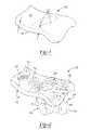
- FIG. 1is a simplified partial perspective view showing only the contour of a bone plate according to the present teachings
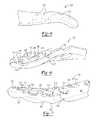
- FIG. 2is a partial perspective view of a plate assembly according to the present teachings
- FIG. 3is a simplified full perspective view of the bone plate shown in FIG. 1 ;
- FIG. 4is a plan view of a portion of the bone plate shown in FIG. 1 ;
- FIG. 5is a partial side perspective view of the bone plate shown in FIG. 3 ;
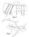
- FIG. 6is a bottom perspective view of a portion of a bone plate according to the present teachings.
- FIG. 7is a top perspective view of the bone plate of FIG. 6 ;
- FIG. 8is an environmental top view of a plate assembly according to the present teachings, shown operatively associated with a bone;
- FIG. 9is an environmental bottom view of the plate assembly of FIG. 8 , shown operatively associated with a bone;
- FIG. 10is an environmental side view of the plate assembly of FIG. 8 , shown operatively associated with a bone;
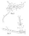
- FIGS. 11 and 12are perspective views of a bone plate shown with a suturing instrument according to the present teachings.
- FIG. 13is a perspective view of a bone plate shown with a graft delivery device according to the present teachings.
- the present teachingscan be used for various plating systems, including, but not limited to, systems for the proximal tibia, the distal tibia, the proximal femur, the distal radius, the humerus, and the elbow.
- the bone plate assembly 100can include a bone plate 102 that has a bone-contacting lower surface 110 and an opposite supper surface 108 .
- the bone-contacting surface 110can be shaped to substantially or generally conform or mate with a corresponding plate-contacting surface of the bone 80 .
- the upper surface 108can be substantially parallel to the lower surface 110 defining a nominal thickness “t”, except in selected surface regions 112 , in which the upper surface 108 has been modified to define an increased thickness t*, as explained below.
- the bone plate 102can include one or more fastener holes 114 for receiving corresponding bone fasteners 104 , and one or more suture holes 120 for receiving sutures and/or guide wires.
- the suture holes 120can be unthreaded and define smooth inner wall for reducing suture damage.
- the suture holes 120can be of a size adequate for passing a suture 152 with a suture instrument 150 , as shown in FIGS. 11 and 12 .
- the suture holes 120can be of smaller diameter than the fastener holes 114 .
- the bone plate 102can also include at least one large non-threaded graft hole 130 for injecting osteobiologics for bone graft applications with a delivery device 200 , as shown in FIG. 13 .
- the graft hole 130can be larger in diameter than the fastener holes 114 .
- the delivery device 200can be, for example, syringe-like, and can include an outer tube 202 and a plunger 204 slidably received in the tube 202 .
- the outer tube 202can include a proximal stop flange 208 and a distal tip portion 206 .
- the delivery device 200can be loaded with the osteobiologic or other graft or pharmacological substance, and the tip portion 206 can be inserted through the graft hole 130 .
- the plunger 204can be pushed toward the stop flange 208 expelling the substance through the tip portion 206 .
- the bone plate 102can also include a fully threaded elongated slot 132 , and an opening 134 formed by two communicating threaded holes for providing the surgeon with choice of two different trajectories for the bone fasteners 104 , as shown in FIGS 8 and 9 .
- the fastener holes 114can be threaded and configured so that they can be used with locking or non-locking bone fasteners 104 .
- Each bone fastener 104can include a head 106 and a bone engaging portion 118 .
- the head 106can be threaded for locking applications, or unthreaded for non-locking applications.
- the fastener holes 114 and the heads 106 of the bone fasteners 104can cooperate by their corresponding threads or other interconnection systems, such as integral or modular interlocking devices including expandable rings, various slotting arrangements, and others, such that the bone fasteners 104 can be locked in a pre-determined orientation, as shown in FIG. 9 , or, in other aspects, allowed to angulate.
- the threads 116can be oriented at an angle relative to the upper surface 108 of the plate 102 , such that the bone fastener 104 can extend along a predetermined direction A defining a trajectory for the orientation of the head 106 of the bone fastener 104 .
- the upper surface 108 of the bone plate 102can be modified to create the surface regions 112 which are shaped such that when the bone fasteners 104 are inserted through the corresponding fastener holes 114 , the heads 106 of the bone fasteners 104 do not protrude above the modified upper surface 108 of the bone plate 102 .
- the heads 106 of the bone fasteners 104are flush with, or recessed, with respect to adjacent portions of the upper surface 108 .
- materialcan be added to the bone plate 102 in a manner that follows the expected trajectory of the head 106 of the fastener 104 throughout a range of orientations, or generally in a manner such that the head 106 remains at or below the upper surface 108 of the bone plate 102 without diminishing the thickness of the bone plate 102 or compromising its strength.
- the upper surface 108 of the bone plate 102can be modified by various methods, including computer-aided processes that determine the expected trajectories of the heads 106 and determine the modifications required for the profile of the bone plate 102 to avoid protrusion of the heads 106 above the upper surface 108 of the bone plate 102 , thereby creating the surface regions 112 which have increased thickness t* relative to the nominal thickness t.
- the bone plate assembly 100 of the present teachingsmay help reduce or substantially eliminate impingement of the heads 106 of the bone fasteners 104 on the surrounding soft tissues.
- the bottom surface 110 of the bone plate 102can define suture-clearance formations 140 placed in relative proximity with corresponding suture holes 120 for facilitating suturing the bone plate 102 through the suture holes 120 and onto muscle tissue associated with the bone 80 in various surgical repair procedures, such as, for example, rotator cuff or other shoulder procedures.
- the suture-clearance formations 140can be located and configured for providing easy access to a suturing instrument 150 carrying a suture 152 , and allowing clearance for suturing manipulation, as shown in FIGS. 11 and 12 .
- the suture-clearance formations 140can be in the form of undulations or recesses sized to accommodate passing of the suturing instrument 150 , which can be a curved or straight suturing needle, for example.
- Each suture-clearance formation 140can extend from a perimeter 142 of bone-contacting surface 110 toward one of the suture holes 120 .
- the shape and placement of the suture-clearance formations 140 in relation to the suture holes 120can facilitate manipulation of the suturing instrument 150 by the operating surgeon.
- the suture-clearance formations 140can define an undulating or wavy shape on the perimeter 142 of the bone-contacting surface 110 .
- the holes 114can provide threading configured and oriented such that the trajectories of the bone fasteners 104 can follow the shape of the underlying bone portion, such as the humeral head 82 , the humeral shaft 84 , or other bone portion.
- the orientation of the bone fasteners associated with the humeral head 82can be at an angle of 30-45 degrees relative to the orientation of the bone fasteners associated with the shaft 84 , as shown in FIG. 10 .
Landscapes
- Health & Medical Sciences (AREA)
- Orthopedic Medicine & Surgery (AREA)
- Life Sciences & Earth Sciences (AREA)
- Surgery (AREA)
- General Health & Medical Sciences (AREA)
- Engineering & Computer Science (AREA)
- Biomedical Technology (AREA)
- Heart & Thoracic Surgery (AREA)
- Animal Behavior & Ethology (AREA)
- Public Health (AREA)
- Veterinary Medicine (AREA)
- Transplantation (AREA)
- Molecular Biology (AREA)
- Medical Informatics (AREA)
- Nuclear Medicine, Radiotherapy & Molecular Imaging (AREA)
- Neurology (AREA)
- Oral & Maxillofacial Surgery (AREA)
- Vascular Medicine (AREA)
- Cardiology (AREA)
- Physical Education & Sports Medicine (AREA)
- Pathology (AREA)
- Surgical Instruments (AREA)
- Prostheses (AREA)
Abstract
Description
Claims (23)
Priority Applications (2)
| Application Number | Priority Date | Filing Date | Title |
|---|---|---|---|
| US11/627,018US8926675B2 (en) | 2006-04-11 | 2007-01-25 | Contoured bone plate |
| US14/564,185US9750550B2 (en) | 2006-04-11 | 2014-12-09 | Contoured bone plate |
Applications Claiming Priority (2)
| Application Number | Priority Date | Filing Date | Title |
|---|---|---|---|
| US79122806P | 2006-04-11 | 2006-04-11 | |
| US11/627,018US8926675B2 (en) | 2006-04-11 | 2007-01-25 | Contoured bone plate |
Related Child Applications (1)
| Application Number | Title | Priority Date | Filing Date |
|---|---|---|---|
| US14/564,185ContinuationUS9750550B2 (en) | 2006-04-11 | 2014-12-09 | Contoured bone plate |
Publications (2)
| Publication Number | Publication Date |
|---|---|
| US20070270853A1 US20070270853A1 (en) | 2007-11-22 |
| US8926675B2true US8926675B2 (en) | 2015-01-06 |
Family
ID=38712922
Family Applications (2)
| Application Number | Title | Priority Date | Filing Date |
|---|---|---|---|
| US11/627,018Active2031-06-20US8926675B2 (en) | 2006-04-11 | 2007-01-25 | Contoured bone plate |
| US14/564,185Expired - Fee RelatedUS9750550B2 (en) | 2006-04-11 | 2014-12-09 | Contoured bone plate |
Family Applications After (1)
| Application Number | Title | Priority Date | Filing Date |
|---|---|---|---|
| US14/564,185Expired - Fee RelatedUS9750550B2 (en) | 2006-04-11 | 2014-12-09 | Contoured bone plate |
Country Status (1)
| Country | Link |
|---|---|
| US (2) | US8926675B2 (en) |
Cited By (39)
| Publication number | Priority date | Publication date | Assignee | Title |
|---|---|---|---|---|
| US20140371798A1 (en)* | 2013-06-13 | 2014-12-18 | James Platt | Channeled bone plate and methods for implanting the same |
| US9649141B2 (en) | 2010-05-07 | 2017-05-16 | Mcginley Engineered Solutions, Llc | System for treating bone fractures |
| US9750550B2 (en) | 2006-04-11 | 2017-09-05 | Biomet Manufacturing, Llc | Contoured bone plate |
| US9833270B2 (en) | 2013-09-19 | 2017-12-05 | Mcginley Engineered Solutions, Llc | Variable angle blade plate system and method |
| US10368928B2 (en) | 2017-03-13 | 2019-08-06 | Globus Medical, Inc. | Bone stabilization systems |
| US10383668B2 (en) | 2016-08-17 | 2019-08-20 | Globus Medical, Inc. | Volar distal radius stabilization system |
| US10420596B2 (en) | 2016-08-17 | 2019-09-24 | Globus Medical, Inc. | Volar distal radius stabilization system |
| US10575884B2 (en) | 2016-08-17 | 2020-03-03 | Globus Medical, Inc. | Fracture plates, systems, and methods |
| US10631903B2 (en) | 2017-03-10 | 2020-04-28 | Globus Medical Inc. | Clavicle fixation system |
| US10687874B2 (en) | 2015-08-27 | 2020-06-23 | Globus Medical, Inc | Proximal humeral stabilization system |
| US10687873B2 (en) | 2016-08-17 | 2020-06-23 | Globus Medical Inc. | Stabilization systems |
| US10751098B2 (en) | 2016-08-17 | 2020-08-25 | Globus Medical Inc. | Stabilization systems |
| US10828075B2 (en) | 2015-09-25 | 2020-11-10 | Globus Medical Inc. | Bone fixation devices having a locking feature |
| US10828074B2 (en) | 2015-11-20 | 2020-11-10 | Globus Medical, Inc. | Expandalbe intramedullary systems and methods of using the same |
| US10856920B2 (en) | 2017-09-13 | 2020-12-08 | Globus Medical Inc. | Bone stabilization systems |
| US10905477B2 (en) | 2017-03-13 | 2021-02-02 | Globus Medical, Inc. | Bone stabilization systems |
| US11071570B2 (en) | 2018-03-02 | 2021-07-27 | Globus Medical, Inc. | Distal tibial plating system |
| US11076898B2 (en) | 2015-08-27 | 2021-08-03 | Globus Medical, Inc. | Proximal humeral stabilization system |
| US11096730B2 (en) | 2017-09-13 | 2021-08-24 | Globus Medical Inc. | Bone stabilization systems |
| US11129627B2 (en) | 2019-10-30 | 2021-09-28 | Globus Medical, Inc. | Method and apparatus for inserting a bone plate |
| US11141172B2 (en) | 2018-04-11 | 2021-10-12 | Globus Medical, Inc. | Method and apparatus for locking a drill guide in a polyaxial hole |
| US11141204B2 (en) | 2016-08-17 | 2021-10-12 | Globus Medical Inc. | Wrist stabilization systems |
| US11197682B2 (en) | 2015-08-27 | 2021-12-14 | Globus Medical, Inc. | Proximal humeral stabilization system |
| US11197704B2 (en) | 2016-04-19 | 2021-12-14 | Globus Medical, Inc. | Implantable compression screws |
| US11197701B2 (en) | 2016-08-17 | 2021-12-14 | Globus Medical, Inc. | Stabilization systems |
| US11202663B2 (en) | 2019-02-13 | 2021-12-21 | Globus Medical, Inc. | Proximal humeral stabilization systems and methods thereof |
| US11213327B2 (en) | 2016-08-17 | 2022-01-04 | Globus Medical, Inc. | Fracture plates, systems, and methods |
| US11224468B2 (en) | 2018-03-02 | 2022-01-18 | Globus Medical, Inc. | Distal tibial plating system |
| US11284920B2 (en) | 2016-03-02 | 2022-03-29 | Globus Medical Inc. | Fixators for bone stabilization and associated systems and methods |
| US11331128B2 (en) | 2016-08-17 | 2022-05-17 | Globus Medical Inc. | Distal radius stabilization system |
| US11432857B2 (en) | 2016-08-17 | 2022-09-06 | Globus Medical, Inc. | Stabilization systems |
| US11707307B2 (en) | 2020-12-04 | 2023-07-25 | Globus Medical, Inc. | Systems and methods for treating rib fractures and osteotomies using implantation |
| US11723647B2 (en) | 2019-12-17 | 2023-08-15 | Globus Medical, Inc. | Syndesmosis fixation assembly |
| US11944361B2 (en) | 2019-08-09 | 2024-04-02 | DePuy Synthes Products, Inc. | Bone plate with structures for attachment of sutures |
| US12042200B2 (en) | 2016-09-22 | 2024-07-23 | Globus Medical, Inc. | Systems and methods for intramedullary nail implantation |
| US12064150B2 (en) | 2022-01-19 | 2024-08-20 | Globus Medical Inc. | System and method for treating bone fractures |
| US12102364B2 (en) | 2020-12-04 | 2024-10-01 | Globus Medical, Inc. | Systems and methods for treating rib fractures and osteotomies using implantation |
| US12185995B2 (en) | 2019-10-09 | 2025-01-07 | Globus Medical, Inc. | Bone stabilization systems |
| US12279795B2 (en) | 2017-09-13 | 2025-04-22 | Globus Medical, Inc. | Bone stabilization systems |
Families Citing this family (26)
| Publication number | Priority date | Publication date | Assignee | Title |
|---|---|---|---|---|
| US8267972B1 (en)* | 2006-12-01 | 2012-09-18 | Gehlert Rick J | Bone plate |
| US8398687B2 (en)* | 2006-12-06 | 2013-03-19 | Amei Technologies, Inc. | Volar plate fixation device |
| US8177849B2 (en) | 2007-05-07 | 2012-05-15 | Zimmer, Inc. | Methods and apparatuses for attaching tissue to orthopaedic implants |
| US20090326591A1 (en)* | 2008-01-29 | 2009-12-31 | Spencer Jr Edwin E | System and method to position and secure fractured bones |
| US8267973B2 (en) | 2008-02-27 | 2012-09-18 | Shoulder Options, Inc. | Fixable suture anchor plate and method for tendon-to-bone repair |
| AU2008354730A1 (en)* | 2008-04-17 | 2009-10-22 | Toby Orthopaedics, Inc. | Soft tissue attachment system and clip |
| US8282674B2 (en)* | 2008-07-18 | 2012-10-09 | Suspension Orthopaedic Solutions, Inc. | Clavicle fixation |
| US8834532B2 (en)* | 2009-07-07 | 2014-09-16 | Zimmer Gmbh | Plate for the treatment of bone fractures |
| FR2956972B1 (en) | 2010-03-08 | 2012-12-28 | Memometal Technologies | ARTICULATED OSTEOSYNTHESIS PLATE |
| FR2956971B1 (en) | 2010-03-08 | 2012-03-02 | Memometal Technologies | PLATE OSTEOSYNTHESIS SYSTEM |
| US20110224736A1 (en)* | 2010-03-09 | 2011-09-15 | Humphrey C Scott | Proximal humerus fracture repair plate and system |
| US8715356B2 (en)* | 2010-04-13 | 2014-05-06 | Biomet Manufacturing, Llc | Prosthetic having a modular soft tissue fixation mechanism |
| CN103079481B (en)* | 2010-08-17 | 2015-11-25 | 雷迪恩斯医药有限责任公司 | For soft tissue being attached to the method and apparatus on bone |
| US8523861B2 (en) | 2010-08-30 | 2013-09-03 | Biomet Manufacturing, Llc | Method and apparatus for osteosynthesis |
| US9259217B2 (en)* | 2012-01-03 | 2016-02-16 | Biomet Manufacturing, Llc | Suture Button |
| US10350078B2 (en)* | 2012-06-27 | 2019-07-16 | Arthrosurface, Inc. | Devices, apparatuses, kits, and methods for repair of articular surface and/or articular rim |
| US9480475B2 (en) | 2012-08-15 | 2016-11-01 | DePuy Synthes Products, Inc. | Bone plate suture anchor |
| EP2730244B1 (en)* | 2012-11-07 | 2017-04-26 | Arthrex, Inc. | Bone plate with suture holes for soft tissue reattachment on the diaphyseal region of the plate |
| US9814503B1 (en)* | 2014-04-14 | 2017-11-14 | Avanti Orthopaedics, LLC | Load sharing bone plate |
| FR3023469B1 (en)* | 2014-07-10 | 2016-08-26 | In2Bones | IMPLANT AND SURGICAL KIT FOR MAINTAINING THE BONE BODIES OF A PATIENT IN RELATION TO OTHERS |
| CA2983488C (en) | 2015-04-24 | 2020-12-22 | Biomet Manufacturing, Llc | Clavicle implants |
| CN106420022B (en)* | 2016-10-20 | 2017-09-08 | 杭州首时科技有限公司 | A kind of intelligent personalized exoskeleton device for fractures |
| CN108742812B (en)* | 2018-05-08 | 2021-01-08 | 中国人民解放军总医院 | Reduction supporting structure for femoral neck fracture |
| CN108378916B (en)* | 2018-05-08 | 2021-01-08 | 中国人民解放军总医院 | Locking steel plate for femoral neck fracture reduction |
| KR102636800B1 (en)* | 2021-10-21 | 2024-02-15 | 가톨릭대학교 산학협력단 | Hybrid scaffold for bone tissue regeneration having window capable of intraosseous access |
| US20250134562A1 (en)* | 2023-10-30 | 2025-05-01 | DePuy Synthes Products, Inc. | Suture hole with funnel on bone plate |
Citations (46)
| Publication number | Priority date | Publication date | Assignee | Title |
|---|---|---|---|---|
| US3463148A (en) | 1966-01-20 | 1969-08-26 | Richards Mfg Co | Bone plate |
| US3716050A (en) | 1971-02-11 | 1973-02-13 | F Johnston | Olecranon plate |
| US5709686A (en) | 1995-03-27 | 1998-01-20 | Synthes (U.S.A.) | Bone plate |
| US5938664A (en) | 1998-03-31 | 1999-08-17 | Zimmer, Inc. | Orthopaedic bone plate |
| US6001099A (en) | 1998-06-08 | 1999-12-14 | Huebner; Randall J. | Bone plate with varying rigidity |
| US6093201A (en)* | 1999-01-19 | 2000-07-25 | Ethicon, Inc. | Biocompatible absorbable polymer plating system for tissue fixation |
| US6096040A (en) | 1996-06-14 | 2000-08-01 | Depuy Ace Medical Company | Upper extremity bone plates |
| US6228085B1 (en) | 1998-07-14 | 2001-05-08 | Theken Surgical Llc | Bone fixation system |
| USD443060S1 (en) | 2000-06-01 | 2001-05-29 | Bristol-Myers Squibb Company | Bone plate |
| US6238969B1 (en)* | 1995-11-13 | 2001-05-29 | Micron Technology, Inc. | Method of forming a capacitor |
| US6309393B1 (en) | 1996-08-12 | 2001-10-30 | Synthes (U.S.A.) | Bone plate |
| USD458684S1 (en) | 2001-11-13 | 2002-06-11 | Zimmer, Inc. | Orthopaedic bone plate |
| USD458996S1 (en) | 2001-11-13 | 2002-06-18 | Zimmer, Inc. | Orthopaedic bone plate |
| USD463559S1 (en) | 2001-11-16 | 2002-09-24 | Zimmer, Inc. | Orthopaedic bone plate |
| USD463558S1 (en) | 2001-11-16 | 2002-09-24 | Zimmer, Inc. | Orthopaedic bone plate |
| USD463557S1 (en) | 2001-11-16 | 2002-09-24 | Zimmer, Inc. | Bone plate |
| USD464136S1 (en) | 2001-11-16 | 2002-10-08 | Zimmer, Inc. | Orthopaedic bone plate |
| USD464731S1 (en) | 2001-11-16 | 2002-10-22 | Zimmer, Inc. | Orthopaedic bone plate |
| USD470588S1 (en) | 2002-04-26 | 2003-02-18 | Zimmer, Inc. | Orthopaedic bone plate |
| US6623486B1 (en)* | 1999-09-13 | 2003-09-23 | Synthes (U.S.A.) | bone plating system |
| US6669701B2 (en) | 2000-01-27 | 2003-12-30 | Synthes (Usa) | Bone plate |
| US6709686B1 (en) | 2003-03-17 | 2004-03-23 | Richard G. Matthew | Potato-based food products tolerable by gluten-intolerant individuals and methods of making and using the same |
| US6719759B2 (en) | 1999-03-09 | 2004-04-13 | Synthes Ag Chur | Bone plate |
| US6730091B1 (en)* | 1999-05-03 | 2004-05-04 | Medartis Ag | Blockable bone plate |
| US20040102777A1 (en) | 2002-11-19 | 2004-05-27 | Huebner Randall J. | Deformable bone plates |
| US20040116930A1 (en) | 2002-06-10 | 2004-06-17 | O'driscoll Shawn W. | Bone plates |
| US20050010226A1 (en)* | 2003-05-30 | 2005-01-13 | Grady Mark P. | Bone plate |
| US20050015089A1 (en) | 2003-03-26 | 2005-01-20 | Young Robert Allan | Locking bone plate |
| US20050070904A1 (en) | 2003-09-29 | 2005-03-31 | Darin Gerlach | Bone plates and bone plate assemblies |
| US20050182405A1 (en)* | 2004-01-23 | 2005-08-18 | Orbay Jorge L. | System for stabilization of fractures of convex articular bone surfaces including subchondral support structure |
| US20050182406A1 (en)* | 2004-01-23 | 2005-08-18 | Orbay Jorge L. | System for stabilization of fractures of convex articular bone surfaces including subchondral support structure |
| US6955677B2 (en) | 2002-10-15 | 2005-10-18 | The University Of North Carolina At Chapel Hill | Multi-angular fastening apparatus and method for surgical bone screw/plate systems |
| US20050240187A1 (en)* | 2004-04-22 | 2005-10-27 | Huebner Randall J | Expanded fixation of bones |
| US20060004361A1 (en) | 2004-06-21 | 2006-01-05 | Garry Hayeck | Bone plate |
| US20060004362A1 (en) | 2004-07-02 | 2006-01-05 | Patterson Chad J | Distal radius bone plating system with locking and non-locking screws |
| US20060009771A1 (en)* | 2000-02-01 | 2006-01-12 | Orbay Jorge L | Bone stabilization system including plate having fixed-angle holes together with unidirectional locking screws and surgeon-directed locking screws |
| US20060035772A1 (en) | 2004-08-16 | 2006-02-16 | Nautilus, Inc. | Attachment and mounting assembly for an exercise bench |
| US7001388B2 (en) | 2004-01-23 | 2006-02-21 | Hand Innovations, Llc | System for stabilization of fractures of convex articular bone surfaces including subchondral support structure |
| US20060116679A1 (en) | 2004-11-30 | 2006-06-01 | Stryker Trauma Sa | Bone plating implants, instruments and methods |
| US20060173458A1 (en) | 2004-10-07 | 2006-08-03 | Micah Forstein | Bone fracture fixation system |
| US20060235400A1 (en)* | 2003-08-26 | 2006-10-19 | Rolf Schneider | Bone plate |
| US20060264947A1 (en)* | 2005-05-20 | 2006-11-23 | Orbay Jorge L | Bone fixation system |
| US20060276896A1 (en)* | 2005-06-02 | 2006-12-07 | Medicinelodge, Inc. | Bone implants with integrated line locks |
| US20070083207A1 (en)* | 2005-09-21 | 2007-04-12 | Tara Ziolo | Variable angle bone fixation assembly |
| US20070088360A1 (en)* | 2005-09-19 | 2007-04-19 | Orbay Jorge L | Bone stabilization system including multi-directional threaded fixation element |
| US20070093835A1 (en)* | 2005-09-19 | 2007-04-26 | Orbay Jorge L | Bone Fixation Plate with Complex Suture Anchor Locations |
Family Cites Families (4)
| Publication number | Priority date | Publication date | Assignee | Title |
|---|---|---|---|---|
| US7118572B2 (en)* | 2003-02-03 | 2006-10-10 | Orthopedic Designs, Inc. | Femoral neck compression screw system with ortho-biologic material delivery capability |
| EP1709921B1 (en)* | 2005-04-04 | 2013-07-03 | Arthrex, Inc. | Bone plate with suture loops |
| US8100952B2 (en)* | 2005-12-22 | 2012-01-24 | Anthem Orthopaedics Llc | Drug delivering bone plate and method and targeting device for use therewith |
| US8926675B2 (en) | 2006-04-11 | 2015-01-06 | Biomet Manufacturing, Llc | Contoured bone plate |
- 2007
- 2007-01-25USUS11/627,018patent/US8926675B2/enactiveActive
- 2014
- 2014-12-09USUS14/564,185patent/US9750550B2/ennot_activeExpired - Fee Related
Patent Citations (51)
| Publication number | Priority date | Publication date | Assignee | Title |
|---|---|---|---|---|
| US3463148A (en) | 1966-01-20 | 1969-08-26 | Richards Mfg Co | Bone plate |
| US3716050A (en) | 1971-02-11 | 1973-02-13 | F Johnston | Olecranon plate |
| US5709686A (en) | 1995-03-27 | 1998-01-20 | Synthes (U.S.A.) | Bone plate |
| US6238969B1 (en)* | 1995-11-13 | 2001-05-29 | Micron Technology, Inc. | Method of forming a capacitor |
| US6096040A (en) | 1996-06-14 | 2000-08-01 | Depuy Ace Medical Company | Upper extremity bone plates |
| US6309393B1 (en) | 1996-08-12 | 2001-10-30 | Synthes (U.S.A.) | Bone plate |
| US5938664A (en) | 1998-03-31 | 1999-08-17 | Zimmer, Inc. | Orthopaedic bone plate |
| US6355042B2 (en) | 1998-03-31 | 2002-03-12 | Bristol-Myers Squibb Company | Orthopaedic bone plate |
| US6001099A (en) | 1998-06-08 | 1999-12-14 | Huebner; Randall J. | Bone plate with varying rigidity |
| US6228085B1 (en) | 1998-07-14 | 2001-05-08 | Theken Surgical Llc | Bone fixation system |
| US6093201A (en)* | 1999-01-19 | 2000-07-25 | Ethicon, Inc. | Biocompatible absorbable polymer plating system for tissue fixation |
| US6719759B2 (en) | 1999-03-09 | 2004-04-13 | Synthes Ag Chur | Bone plate |
| US6730091B1 (en)* | 1999-05-03 | 2004-05-04 | Medartis Ag | Blockable bone plate |
| US6623486B1 (en)* | 1999-09-13 | 2003-09-23 | Synthes (U.S.A.) | bone plating system |
| US20050080421A1 (en)* | 1999-09-13 | 2005-04-14 | Synthes (Usa) | Bone plating system |
| US20040059335A1 (en) | 1999-09-13 | 2004-03-25 | Synthes (U.S.A.) | Bone plating system |
| US20040059334A1 (en)* | 1999-09-13 | 2004-03-25 | Synthes (U.S.A.) | Bone plating system |
| US6669701B2 (en) | 2000-01-27 | 2003-12-30 | Synthes (Usa) | Bone plate |
| US20060009771A1 (en)* | 2000-02-01 | 2006-01-12 | Orbay Jorge L | Bone stabilization system including plate having fixed-angle holes together with unidirectional locking screws and surgeon-directed locking screws |
| USD443060S1 (en) | 2000-06-01 | 2001-05-29 | Bristol-Myers Squibb Company | Bone plate |
| USD458684S1 (en) | 2001-11-13 | 2002-06-11 | Zimmer, Inc. | Orthopaedic bone plate |
| USD458996S1 (en) | 2001-11-13 | 2002-06-18 | Zimmer, Inc. | Orthopaedic bone plate |
| USD464731S1 (en) | 2001-11-16 | 2002-10-22 | Zimmer, Inc. | Orthopaedic bone plate |
| USD464136S1 (en) | 2001-11-16 | 2002-10-08 | Zimmer, Inc. | Orthopaedic bone plate |
| USD463557S1 (en) | 2001-11-16 | 2002-09-24 | Zimmer, Inc. | Bone plate |
| USD463558S1 (en) | 2001-11-16 | 2002-09-24 | Zimmer, Inc. | Orthopaedic bone plate |
| USD463559S1 (en) | 2001-11-16 | 2002-09-24 | Zimmer, Inc. | Orthopaedic bone plate |
| USD470588S1 (en) | 2002-04-26 | 2003-02-18 | Zimmer, Inc. | Orthopaedic bone plate |
| US20040116930A1 (en) | 2002-06-10 | 2004-06-17 | O'driscoll Shawn W. | Bone plates |
| US6955677B2 (en) | 2002-10-15 | 2005-10-18 | The University Of North Carolina At Chapel Hill | Multi-angular fastening apparatus and method for surgical bone screw/plate systems |
| US20040102777A1 (en) | 2002-11-19 | 2004-05-27 | Huebner Randall J. | Deformable bone plates |
| US6709686B1 (en) | 2003-03-17 | 2004-03-23 | Richard G. Matthew | Potato-based food products tolerable by gluten-intolerant individuals and methods of making and using the same |
| US20050015089A1 (en) | 2003-03-26 | 2005-01-20 | Young Robert Allan | Locking bone plate |
| US20050010226A1 (en)* | 2003-05-30 | 2005-01-13 | Grady Mark P. | Bone plate |
| US20060235400A1 (en)* | 2003-08-26 | 2006-10-19 | Rolf Schneider | Bone plate |
| US20050107796A1 (en) | 2003-09-29 | 2005-05-19 | Darin Gerlach | Bone plates and methods for provisional fixation using same |
| US20050070904A1 (en) | 2003-09-29 | 2005-03-31 | Darin Gerlach | Bone plates and bone plate assemblies |
| US20050182406A1 (en)* | 2004-01-23 | 2005-08-18 | Orbay Jorge L. | System for stabilization of fractures of convex articular bone surfaces including subchondral support structure |
| US7001388B2 (en) | 2004-01-23 | 2006-02-21 | Hand Innovations, Llc | System for stabilization of fractures of convex articular bone surfaces including subchondral support structure |
| US20050182405A1 (en)* | 2004-01-23 | 2005-08-18 | Orbay Jorge L. | System for stabilization of fractures of convex articular bone surfaces including subchondral support structure |
| US20050240187A1 (en)* | 2004-04-22 | 2005-10-27 | Huebner Randall J | Expanded fixation of bones |
| US20060004361A1 (en) | 2004-06-21 | 2006-01-05 | Garry Hayeck | Bone plate |
| US20060004362A1 (en) | 2004-07-02 | 2006-01-05 | Patterson Chad J | Distal radius bone plating system with locking and non-locking screws |
| US20060035772A1 (en) | 2004-08-16 | 2006-02-16 | Nautilus, Inc. | Attachment and mounting assembly for an exercise bench |
| US20060173458A1 (en) | 2004-10-07 | 2006-08-03 | Micah Forstein | Bone fracture fixation system |
| US20060116679A1 (en) | 2004-11-30 | 2006-06-01 | Stryker Trauma Sa | Bone plating implants, instruments and methods |
| US20060264947A1 (en)* | 2005-05-20 | 2006-11-23 | Orbay Jorge L | Bone fixation system |
| US20060276896A1 (en)* | 2005-06-02 | 2006-12-07 | Medicinelodge, Inc. | Bone implants with integrated line locks |
| US20070088360A1 (en)* | 2005-09-19 | 2007-04-19 | Orbay Jorge L | Bone stabilization system including multi-directional threaded fixation element |
| US20070093835A1 (en)* | 2005-09-19 | 2007-04-26 | Orbay Jorge L | Bone Fixation Plate with Complex Suture Anchor Locations |
| US20070083207A1 (en)* | 2005-09-21 | 2007-04-12 | Tara Ziolo | Variable angle bone fixation assembly |
Cited By (84)
| Publication number | Priority date | Publication date | Assignee | Title |
|---|---|---|---|---|
| US9750550B2 (en) | 2006-04-11 | 2017-09-05 | Biomet Manufacturing, Llc | Contoured bone plate |
| US9649141B2 (en) | 2010-05-07 | 2017-05-16 | Mcginley Engineered Solutions, Llc | System for treating bone fractures |
| US10111688B2 (en) | 2010-05-07 | 2018-10-30 | Mcginley Engineered Solutions, Llc | System for treating bone fractures |
| US20140371798A1 (en)* | 2013-06-13 | 2014-12-18 | James Platt | Channeled bone plate and methods for implanting the same |
| US9700360B2 (en)* | 2013-06-13 | 2017-07-11 | James Platt | Channeled bone plate and methods for implanting the same |
| US9833270B2 (en) | 2013-09-19 | 2017-12-05 | Mcginley Engineered Solutions, Llc | Variable angle blade plate system and method |
| US10117689B2 (en) | 2013-09-19 | 2018-11-06 | Mcginley Engineered Solutions, Llc | Variable angle blade plate system and method |
| US11931083B2 (en) | 2015-08-27 | 2024-03-19 | Globus Medical Inc. | Proximal humeral stabilization system |
| US12059160B2 (en) | 2015-08-27 | 2024-08-13 | Globus Medical Inc. | Proximal humeral stabilization system |
| US10687874B2 (en) | 2015-08-27 | 2020-06-23 | Globus Medical, Inc | Proximal humeral stabilization system |
| US11197682B2 (en) | 2015-08-27 | 2021-12-14 | Globus Medical, Inc. | Proximal humeral stabilization system |
| US11076898B2 (en) | 2015-08-27 | 2021-08-03 | Globus Medical, Inc. | Proximal humeral stabilization system |
| US11617606B2 (en) | 2015-08-27 | 2023-04-04 | Globus Medical Inc. | Proximal humeral stabilization system |
| US10828075B2 (en) | 2015-09-25 | 2020-11-10 | Globus Medical Inc. | Bone fixation devices having a locking feature |
| US10828074B2 (en) | 2015-11-20 | 2020-11-10 | Globus Medical, Inc. | Expandalbe intramedullary systems and methods of using the same |
| US11284920B2 (en) | 2016-03-02 | 2022-03-29 | Globus Medical Inc. | Fixators for bone stabilization and associated systems and methods |
| US12042180B2 (en) | 2016-03-02 | 2024-07-23 | Globus Medical Inc. | Fixators for bone stabilization and associated systems and methods |
| US11980404B2 (en) | 2016-04-19 | 2024-05-14 | Globus Medical, Inc. | Implantable compression screws |
| US11197704B2 (en) | 2016-04-19 | 2021-12-14 | Globus Medical, Inc. | Implantable compression screws |
| US12295626B2 (en) | 2016-08-17 | 2025-05-13 | Globus Medical, Inc. | Stabilization systems |
| US11986225B2 (en) | 2016-08-17 | 2024-05-21 | Globus Medical Inc. | Distal radius stabilization system |
| US12256965B2 (en) | 2016-08-17 | 2025-03-25 | Global Medical, Inc. | Wrist stabilization systems |
| US12295627B2 (en) | 2016-08-17 | 2025-05-13 | Globus Medical, Inc. | Stabilization systems |
| US10751098B2 (en) | 2016-08-17 | 2020-08-25 | Globus Medical Inc. | Stabilization systems |
| US12004790B2 (en) | 2016-08-17 | 2024-06-11 | Globus Medical, Inc | Volar distal radius stabilization system |
| US11992252B2 (en) | 2016-08-17 | 2024-05-28 | Globus Medical, Inc. | Distal radius stabilization system |
| US11141204B2 (en) | 2016-08-17 | 2021-10-12 | Globus Medical Inc. | Wrist stabilization systems |
| US11147599B2 (en) | 2016-08-17 | 2021-10-19 | Globus Medical Inc. | Systems and methods for bone fixation anchor, plate, and spacer devices |
| US11160590B2 (en) | 2016-08-17 | 2021-11-02 | Globus Medical, Inc. | Volar distal radius stabilization system |
| US10687873B2 (en) | 2016-08-17 | 2020-06-23 | Globus Medical Inc. | Stabilization systems |
| US11832857B2 (en) | 2016-08-17 | 2023-12-05 | Globus Medical, Inc. | Fracture plates, systems, and methods |
| US11197701B2 (en) | 2016-08-17 | 2021-12-14 | Globus Medical, Inc. | Stabilization systems |
| US12245799B2 (en) | 2016-08-17 | 2025-03-11 | Globus Medical, Inc. | Fracture plates, systems, and methods |
| US11213327B2 (en) | 2016-08-17 | 2022-01-04 | Globus Medical, Inc. | Fracture plates, systems, and methods |
| US10575884B2 (en) | 2016-08-17 | 2020-03-03 | Globus Medical, Inc. | Fracture plates, systems, and methods |
| US11957389B2 (en) | 2016-08-17 | 2024-04-16 | Globus Medical, Inc. | Systems and methods for bone fixation anchor, plate, and spacer devices |
| US11278332B2 (en) | 2016-08-17 | 2022-03-22 | Globus Medical, Inc. | Distal radius stabilization system |
| US10420596B2 (en) | 2016-08-17 | 2019-09-24 | Globus Medical, Inc. | Volar distal radius stabilization system |
| US11331128B2 (en) | 2016-08-17 | 2022-05-17 | Globus Medical Inc. | Distal radius stabilization system |
| US10383668B2 (en) | 2016-08-17 | 2019-08-20 | Globus Medical, Inc. | Volar distal radius stabilization system |
| US11432857B2 (en) | 2016-08-17 | 2022-09-06 | Globus Medical, Inc. | Stabilization systems |
| US11896271B2 (en) | 2016-08-17 | 2024-02-13 | Globus Medical, Inc. | Stabilization systems |
| US11612422B2 (en) | 2016-08-17 | 2023-03-28 | Globus Medical Inc. | Stabilization systems |
| US12408958B2 (en) | 2016-08-17 | 2025-09-09 | Globus Medical, Inc. | Distal radius stabilization system |
| US12042200B2 (en) | 2016-09-22 | 2024-07-23 | Globus Medical, Inc. | Systems and methods for intramedullary nail implantation |
| US10881438B2 (en) | 2017-03-10 | 2021-01-05 | Globus Medical, Inc. | Clavicle fixation system |
| US12161372B2 (en) | 2017-03-10 | 2024-12-10 | Globus Medical, Inc. | Clavicle fixation system |
| US11857229B2 (en) | 2017-03-10 | 2024-01-02 | Globus Medical, Inc. | Clavicle fixation system |
| US10631903B2 (en) | 2017-03-10 | 2020-04-28 | Globus Medical Inc. | Clavicle fixation system |
| US11357554B2 (en) | 2017-03-10 | 2022-06-14 | Globus Medical Inc. | Clavicle fixation system |
| US11058467B2 (en) | 2017-03-13 | 2021-07-13 | Globus Medical, Inc. | Bone stabilization systems |
| US10368928B2 (en) | 2017-03-13 | 2019-08-06 | Globus Medical, Inc. | Bone stabilization systems |
| US12089883B2 (en) | 2017-03-13 | 2024-09-17 | Globus Medical, Inc. | Bone stabilization systems |
| US10905477B2 (en) | 2017-03-13 | 2021-02-02 | Globus Medical, Inc. | Bone stabilization systems |
| US11607254B2 (en) | 2017-09-13 | 2023-03-21 | Globus Medical, Inc. | Bone stabilization systems |
| US11871970B2 (en) | 2017-09-13 | 2024-01-16 | Globus Medical, Inc | Bone stabilization systems |
| US12279795B2 (en) | 2017-09-13 | 2025-04-22 | Globus Medical, Inc. | Bone stabilization systems |
| US10856920B2 (en) | 2017-09-13 | 2020-12-08 | Globus Medical Inc. | Bone stabilization systems |
| US12390254B2 (en) | 2017-09-13 | 2025-08-19 | Globus Medical Inc. | Bone stabilization systems |
| US12318122B2 (en) | 2017-09-13 | 2025-06-03 | Globus Medical, Inc. | Bone stabilization systems |
| US12042194B2 (en) | 2017-09-13 | 2024-07-23 | Globus Medical Inc. | Bone stabilization systems |
| US11096730B2 (en) | 2017-09-13 | 2021-08-24 | Globus Medical Inc. | Bone stabilization systems |
| US12343051B2 (en) | 2018-03-02 | 2025-07-01 | Globus Medical, Inc. | Distal tibial plating system |
| US11071570B2 (en) | 2018-03-02 | 2021-07-27 | Globus Medical, Inc. | Distal tibial plating system |
| US12102363B2 (en) | 2018-03-02 | 2024-10-01 | Globus Medical Inc. | Distal tibial plating system |
| US11224468B2 (en) | 2018-03-02 | 2022-01-18 | Globus Medical, Inc. | Distal tibial plating system |
| US11771480B2 (en) | 2018-03-02 | 2023-10-03 | Globus Medical, Inc. | Distal tibial plating system |
| US11141172B2 (en) | 2018-04-11 | 2021-10-12 | Globus Medical, Inc. | Method and apparatus for locking a drill guide in a polyaxial hole |
| US11779354B2 (en) | 2018-04-11 | 2023-10-10 | Globus Medical Inc. | Method and apparatus for locking a drill guide in a polyaxial hole |
| US11259848B2 (en) | 2019-02-13 | 2022-03-01 | Globus Medical, Inc. | Proximal humeral stabilization systems and methods thereof |
| US12076063B2 (en) | 2019-02-13 | 2024-09-03 | Globus Medical, Inc. | Proximal humeral stabilization systems and methods thereof |
| US11202663B2 (en) | 2019-02-13 | 2021-12-21 | Globus Medical, Inc. | Proximal humeral stabilization systems and methods thereof |
| US12185993B2 (en) | 2019-02-13 | 2025-01-07 | Globus Medical, Inc. | Proximal humeral stabilization systems and methods thereof |
| US11944361B2 (en) | 2019-08-09 | 2024-04-02 | DePuy Synthes Products, Inc. | Bone plate with structures for attachment of sutures |
| US12185995B2 (en) | 2019-10-09 | 2025-01-07 | Globus Medical, Inc. | Bone stabilization systems |
| US12245776B2 (en) | 2019-10-30 | 2025-03-11 | Globus Medical, Inc. | Method and apparatus for inserting a bone plate |
| US11129627B2 (en) | 2019-10-30 | 2021-09-28 | Globus Medical, Inc. | Method and apparatus for inserting a bone plate |
| US11826060B2 (en) | 2019-10-30 | 2023-11-28 | Globus Medical Inc. | Method and apparatus for inserting a bone plate |
| US12114850B2 (en) | 2019-12-17 | 2024-10-15 | Globus Medical, Inc. | Syndesmosis fixation assembly |
| US11723647B2 (en) | 2019-12-17 | 2023-08-15 | Globus Medical, Inc. | Syndesmosis fixation assembly |
| US12102364B2 (en) | 2020-12-04 | 2024-10-01 | Globus Medical, Inc. | Systems and methods for treating rib fractures and osteotomies using implantation |
| US12369958B2 (en) | 2020-12-04 | 2025-07-29 | Globus Medical, Inc. | Systems and methods for treating rib fractures and osteotomies using implantation |
| US11707307B2 (en) | 2020-12-04 | 2023-07-25 | Globus Medical, Inc. | Systems and methods for treating rib fractures and osteotomies using implantation |
| US12064150B2 (en) | 2022-01-19 | 2024-08-20 | Globus Medical Inc. | System and method for treating bone fractures |
Also Published As
| Publication number | Publication date |
|---|---|
| US20070270853A1 (en) | 2007-11-22 |
| US9750550B2 (en) | 2017-09-05 |
| US20150094810A1 (en) | 2015-04-02 |
Similar Documents
| Publication | Publication Date | Title |
|---|---|---|
| US8926675B2 (en) | Contoured bone plate | |
| US12256965B2 (en) | Wrist stabilization systems | |
| US9855083B2 (en) | Bone plate with elevated suture hole structures | |
| US12004790B2 (en) | Volar distal radius stabilization system | |
| US7695472B2 (en) | Locking bone plate | |
| US7722653B2 (en) | Locking bone plate | |
| JP6794506B2 (en) | Bone stabilization system | |
| US7905883B2 (en) | Locking triple pelvic osteotomy plate and method of use | |
| KR101408732B1 (en) | Bone plate with adjacent holes connected by the complex and relief-space | |
| EP1906850B1 (en) | Bone plates with movable locking elements | |
| US20160166297A1 (en) | Bone plate with elevated suture hole structures | |
| US20080045960A1 (en) | Locking tpo plate and method of use | |
| US12042194B2 (en) | Bone stabilization systems | |
| JP2018171446A (en) | Proximal humeral stabilization system | |
| JP2018525164A (en) | Proximal humerus stabilization system | |
| JP6883056B2 (en) | Bone stabilization system | |
| US12408958B2 (en) | Distal radius stabilization system | |
| AU2020351246B2 (en) | Tibial plateau leveling osteotomy plate with offset | |
| EP3449877B1 (en) | Implant for use in a total ankle replacement system |
Legal Events
| Date | Code | Title | Description |
|---|---|---|---|
| AS | Assignment | Owner name:EBI, L.P., NEW JERSEY Free format text:ASSIGNMENT OF ASSIGNORS INTEREST;ASSIGNOR:LEUNG, ROSS T.;REEL/FRAME:018804/0432 Effective date:20070124 | |
| AS | Assignment | Owner name:BANK OF AMERICA, N.A., AS ADMINISTRATIVE AGENT FOR Free format text:SECURITY AGREEMENT;ASSIGNORS:LVB ACQUISITION, INC.;BIOMET, INC.;REEL/FRAME:020362/0001 Effective date:20070925 | |
| AS | Assignment | Owner name:EBI, LLC, NEW JERSEY Free format text:CHANGE OF NAME;ASSIGNOR:EBI, INC.;REEL/FRAME:021387/0450 Effective date:20080227 Owner name:EBI, LLC,NEW JERSEY Free format text:CHANGE OF NAME;ASSIGNOR:EBI, INC.;REEL/FRAME:021387/0450 Effective date:20080227 | |
| AS | Assignment | Owner name:EBI, LLC, NEW JERSEY Free format text:CORRECTIVE ASSIGNMENT TO CORRECT THE ASSIGNOR INCORRECTLY IDENTIFIED AS EBI, INC. ON ORIGINAL RECORDATION COVERSHEET SHOULD HAVE BEEN IDENTIFIED AS EBI, L.P. PREVIOUSLY RECORDED ON REEL 021387 FRAME 0450;ASSIGNOR:EBI, L.P.;REEL/FRAME:022727/0859 Effective date:20080227 Owner name:EBI, LLC,NEW JERSEY Free format text:CORRECTIVE ASSIGNMENT TO CORRECT THE ASSIGNOR INCORRECTLY IDENTIFIED AS EBI, INC. ON ORIGINAL RECORDATION COVERSHEET SHOULD HAVE BEEN IDENTIFIED AS EBI, L.P. PREVIOUSLY RECORDED ON REEL 021387 FRAME 0450. ASSIGNOR(S) HEREBY CONFIRMS THE ORIGINAL CONVEYANCE TEXT APPEARING IN NAME CHANGE DOCUMENTATION REFLECTS EBI, L.P. IS NOW KNOWN AS EBI, LLC.;ASSIGNOR:EBI, L.P.;REEL/FRAME:022727/0859 Effective date:20080227 Owner name:EBI, LLC, NEW JERSEY Free format text:CORRECTIVE ASSIGNMENT TO CORRECT THE ASSIGNOR INCORRECTLY IDENTIFIED AS EBI, INC. ON ORIGINAL RECORDATION COVERSHEET SHOULD HAVE BEEN IDENTIFIED AS EBI, L.P. PREVIOUSLY RECORDED ON REEL 021387 FRAME 0450. ASSIGNOR(S) HEREBY CONFIRMS THE ORIGINAL CONVEYANCE TEXT APPEARING IN NAME CHANGE DOCUMENTATION REFLECTS EBI, L.P. IS NOW KNOWN AS EBI, LLC.;ASSIGNOR:EBI, L.P.;REEL/FRAME:022727/0859 Effective date:20080227 | |
| AS | Assignment | Owner name:BIOMET MANUFACTURING, LLC, INDIANA Free format text:ASSIGNMENT OF ASSIGNORS INTEREST;ASSIGNOR:EBI, LLC;REEL/FRAME:031307/0797 Effective date:20130925 | |
| AS | Assignment | Owner name:BIOMET MANUFACTURING, LLC, INDIANA Free format text:ASSIGNMENT OF ASSIGNORS INTEREST;ASSIGNOR:MILFORD, JORDAN N;REEL/FRAME:034081/0048 Effective date:20140923 | |
| STCF | Information on status: patent grant | Free format text:PATENTED CASE | |
| AS | Assignment | Owner name:BIOMET, INC., INDIANA Free format text:RELEASE OF SECURITY INTEREST IN PATENTS RECORDED AT REEL 020362/ FRAME 0001;ASSIGNOR:BANK OF AMERICA, N.A., AS ADMINISTRATIVE AGENT;REEL/FRAME:037155/0133 Effective date:20150624 Owner name:LVB ACQUISITION, INC., INDIANA Free format text:RELEASE OF SECURITY INTEREST IN PATENTS RECORDED AT REEL 020362/ FRAME 0001;ASSIGNOR:BANK OF AMERICA, N.A., AS ADMINISTRATIVE AGENT;REEL/FRAME:037155/0133 Effective date:20150624 | |
| MAFP | Maintenance fee payment | Free format text:PAYMENT OF MAINTENANCE FEE, 4TH YEAR, LARGE ENTITY (ORIGINAL EVENT CODE: M1551) Year of fee payment:4 | |
| MAFP | Maintenance fee payment | Free format text:PAYMENT OF MAINTENANCE FEE, 8TH YEAR, LARGE ENTITY (ORIGINAL EVENT CODE: M1552); ENTITY STATUS OF PATENT OWNER: LARGE ENTITY Year of fee payment:8 |