US8926605B2 - Systems and methods for radiometrically measuring temperature during tissue ablation - Google Patents
Systems and methods for radiometrically measuring temperature during tissue ablationDownload PDFInfo
- Publication number
- US8926605B2 US8926605B2US13/368,112US201213368112AUS8926605B2US 8926605 B2US8926605 B2US 8926605B2US 201213368112 AUS201213368112 AUS 201213368112AUS 8926605 B2US8926605 B2US 8926605B2
- Authority
- US
- United States
- Prior art keywords
- temperature
- catheter
- radiometer
- ablation
- ict
- Prior art date
- Legal status (The legal status is an assumption and is not a legal conclusion. Google has not performed a legal analysis and makes no representation as to the accuracy of the status listed.)
- Active, expires
Links
- 238000002679ablationMethods0.000titleclaimsabstractdescription104
- 238000000034methodMethods0.000titleabstractdescription89
- 238000004891communicationMethods0.000claimsabstractdescription23
- 239000012530fluidSubstances0.000claimsdescription28
- 230000002262irrigationEffects0.000claimsdescription24
- 238000003973irrigationMethods0.000claimsdescription24
- 238000009529body temperature measurementMethods0.000claimsdescription16
- 230000004044responseEffects0.000claimsdescription7
- 238000002604ultrasonographyMethods0.000claimsdescription4
- 230000003213activating effectEffects0.000claims1
- 210000001519tissueAnatomy0.000description56
- 239000004020conductorSubstances0.000description41
- 230000037361pathwayEffects0.000description20
- 238000007674radiofrequency ablationMethods0.000description20
- 238000010438heat treatmentMethods0.000description11
- 239000000523sampleSubstances0.000description11
- 230000007831electrophysiologyEffects0.000description10
- 238000002001electrophysiologyMethods0.000description10
- 239000000758substrateSubstances0.000description10
- 230000005540biological transmissionEffects0.000description9
- 210000005003heart tissueAnatomy0.000description9
- 230000003287optical effectEffects0.000description9
- 230000005693optoelectronicsEffects0.000description9
- 230000001594aberrant effectEffects0.000description8
- 238000012544monitoring processMethods0.000description8
- 238000011282treatmentMethods0.000description7
- 238000004364calculation methodMethods0.000description6
- 125000006850spacer groupChemical group0.000description6
- 239000003990capacitorSubstances0.000description5
- 238000013153catheter ablationMethods0.000description5
- 230000008859changeEffects0.000description5
- 206010003662Atrial flutterDiseases0.000description4
- 206010020843HyperthermiaDiseases0.000description4
- 206010003119arrhythmiaDiseases0.000description4
- 230000000694effectsEffects0.000description4
- 210000001174endocardiumAnatomy0.000description4
- 230000006870functionEffects0.000description4
- 230000036031hyperthermiaEffects0.000description4
- 239000004593EpoxySubstances0.000description3
- 241000282412HomoSpecies0.000description3
- 210000004369bloodAnatomy0.000description3
- 239000008280bloodSubstances0.000description3
- 230000008878couplingEffects0.000description3
- 238000010168coupling processMethods0.000description3
- 238000005859coupling reactionMethods0.000description3
- 238000002474experimental methodMethods0.000description3
- 238000005259measurementMethods0.000description3
- 239000000853adhesiveSubstances0.000description2
- 230000001070adhesive effectEffects0.000description2
- 230000006793arrhythmiaEffects0.000description2
- 230000015572biosynthetic processEffects0.000description2
- 230000000747cardiac effectEffects0.000description2
- 239000004568cementSubstances0.000description2
- 230000006378damageEffects0.000description2
- 238000001514detection methodMethods0.000description2
- 238000005516engineering processMethods0.000description2
- 238000007667floatingMethods0.000description2
- 238000009499grossingMethods0.000description2
- 239000002184metalSubstances0.000description2
- 229910052751metalInorganic materials0.000description2
- 238000012986modificationMethods0.000description2
- 230000004048modificationEffects0.000description2
- 210000004165myocardiumAnatomy0.000description2
- 230000003071parasitic effectEffects0.000description2
- 230000002085persistent effectEffects0.000description2
- 239000004810polytetrafluoroethyleneSubstances0.000description2
- 229920001343polytetrafluoroethylenePolymers0.000description2
- 210000000689upper legAnatomy0.000description2
- 210000005166vasculatureAnatomy0.000description2
- 241001465754MetazoaSpecies0.000description1
- 206010028980NeoplasmDiseases0.000description1
- 230000002159abnormal effectEffects0.000description1
- 210000003484anatomyAnatomy0.000description1
- 230000036772blood pressureEffects0.000description1
- 229910052799carbonInorganic materials0.000description1
- 230000015556catabolic processEffects0.000description1
- 239000000919ceramicSubstances0.000description1
- 238000010276constructionMethods0.000description1
- 238000007796conventional methodMethods0.000description1
- 239000002826coolantSubstances0.000description1
- 238000001816coolingMethods0.000description1
- 238000006731degradation reactionMethods0.000description1
- 230000000593degrading effectEffects0.000description1
- 229910003460diamondInorganic materials0.000description1
- 239000010432diamondSubstances0.000description1
- 239000003989dielectric materialSubstances0.000description1
- 208000037265diseases, disorders, signs and symptomsDiseases0.000description1
- 208000035475disorderDiseases0.000description1
- 239000012777electrically insulating materialSubstances0.000description1
- ZZUFCTLCJUWOSV-UHFFFAOYSA-NfurosemideChemical compoundC1=C(Cl)C(S(=O)(=O)N)=CC(C(O)=O)=C1NCC1=CC=CO1ZZUFCTLCJUWOSV-UHFFFAOYSA-N0.000description1
- PCHJSUWPFVWCPO-UHFFFAOYSA-NgoldChemical compound[Au]PCHJSUWPFVWCPO-UHFFFAOYSA-N0.000description1
- 239000010931goldSubstances0.000description1
- 229910052737goldInorganic materials0.000description1
- 238000003384imaging methodMethods0.000description1
- 238000002955isolationMethods0.000description1
- 230000003902lesionEffects0.000description1
- 239000004973liquid crystal related substanceSubstances0.000description1
- 238000013507mappingMethods0.000description1
- 239000000463materialSubstances0.000description1
- 230000008447perceptionEffects0.000description1
- 230000000737periodic effectEffects0.000description1
- 238000003825pressingMethods0.000description1
- 230000008569processEffects0.000description1
- 238000005086pumpingMethods0.000description1
- 238000012552reviewMethods0.000description1
- 230000035945sensitivityEffects0.000description1
- 239000007787solidSubstances0.000description1
- 230000000451tissue damageEffects0.000description1
- 231100000827tissue damageToxicity0.000description1
- 230000001960triggered effectEffects0.000description1
Images


Classifications
- A—HUMAN NECESSITIES
- A61—MEDICAL OR VETERINARY SCIENCE; HYGIENE
- A61B—DIAGNOSIS; SURGERY; IDENTIFICATION
- A61B18/00—Surgical instruments, devices or methods for transferring non-mechanical forms of energy to or from the body
- A61B18/04—Surgical instruments, devices or methods for transferring non-mechanical forms of energy to or from the body by heating
- A61B18/12—Surgical instruments, devices or methods for transferring non-mechanical forms of energy to or from the body by heating by passing a current through the tissue to be heated, e.g. high-frequency current
- A61B18/14—Probes or electrodes therefor
- A61B18/1492—Probes or electrodes therefor having a flexible, catheter-like structure, e.g. for heart ablation
- A—HUMAN NECESSITIES
- A61—MEDICAL OR VETERINARY SCIENCE; HYGIENE
- A61B—DIAGNOSIS; SURGERY; IDENTIFICATION
- A61B18/00—Surgical instruments, devices or methods for transferring non-mechanical forms of energy to or from the body
- A61B18/02—Surgical instruments, devices or methods for transferring non-mechanical forms of energy to or from the body by cooling, e.g. cryogenic techniques
- A—HUMAN NECESSITIES
- A61—MEDICAL OR VETERINARY SCIENCE; HYGIENE
- A61B—DIAGNOSIS; SURGERY; IDENTIFICATION
- A61B18/00—Surgical instruments, devices or methods for transferring non-mechanical forms of energy to or from the body
- A61B18/04—Surgical instruments, devices or methods for transferring non-mechanical forms of energy to or from the body by heating
- A61B18/12—Surgical instruments, devices or methods for transferring non-mechanical forms of energy to or from the body by heating by passing a current through the tissue to be heated, e.g. high-frequency current
- A61B18/1206—Generators therefor
- A—HUMAN NECESSITIES
- A61—MEDICAL OR VETERINARY SCIENCE; HYGIENE
- A61B—DIAGNOSIS; SURGERY; IDENTIFICATION
- A61B18/00—Surgical instruments, devices or methods for transferring non-mechanical forms of energy to or from the body
- A61B18/18—Surgical instruments, devices or methods for transferring non-mechanical forms of energy to or from the body by applying electromagnetic radiation, e.g. microwaves
- A61B18/1815—Surgical instruments, devices or methods for transferring non-mechanical forms of energy to or from the body by applying electromagnetic radiation, e.g. microwaves using microwaves
- A—HUMAN NECESSITIES
- A61—MEDICAL OR VETERINARY SCIENCE; HYGIENE
- A61B—DIAGNOSIS; SURGERY; IDENTIFICATION
- A61B5/00—Measuring for diagnostic purposes; Identification of persons
- A61B5/01—Measuring temperature of body parts ; Diagnostic temperature sensing, e.g. for malignant or inflamed tissue
- A61B5/015—By temperature mapping of body part
- A—HUMAN NECESSITIES
- A61—MEDICAL OR VETERINARY SCIENCE; HYGIENE
- A61B—DIAGNOSIS; SURGERY; IDENTIFICATION
- A61B5/00—Measuring for diagnostic purposes; Identification of persons
- A61B5/24—Detecting, measuring or recording bioelectric or biomagnetic signals of the body or parts thereof
- A61B5/316—Modalities, i.e. specific diagnostic methods
- A61B5/318—Heart-related electrical modalities, e.g. electrocardiography [ECG]
- A61B5/33—Heart-related electrical modalities, e.g. electrocardiography [ECG] specially adapted for cooperation with other devices
- A—HUMAN NECESSITIES
- A61—MEDICAL OR VETERINARY SCIENCE; HYGIENE
- A61B—DIAGNOSIS; SURGERY; IDENTIFICATION
- A61B17/00—Surgical instruments, devices or methods
- A61B2017/00017—Electrical control of surgical instruments
- A61B2017/00022—Sensing or detecting at the treatment site
- A61B2017/00057—Light
- A61B2017/00066—Light intensity
- A61B2017/0007—Pyrometers
- A—HUMAN NECESSITIES
- A61—MEDICAL OR VETERINARY SCIENCE; HYGIENE
- A61B—DIAGNOSIS; SURGERY; IDENTIFICATION
- A61B18/00—Surgical instruments, devices or methods for transferring non-mechanical forms of energy to or from the body
- A61B2018/00005—Cooling or heating of the probe or tissue immediately surrounding the probe
- A61B2018/00011—Cooling or heating of the probe or tissue immediately surrounding the probe with fluids
- A61B2018/00029—Cooling or heating of the probe or tissue immediately surrounding the probe with fluids open
- A—HUMAN NECESSITIES
- A61—MEDICAL OR VETERINARY SCIENCE; HYGIENE
- A61B—DIAGNOSIS; SURGERY; IDENTIFICATION
- A61B18/00—Surgical instruments, devices or methods for transferring non-mechanical forms of energy to or from the body
- A61B2018/00315—Surgical instruments, devices or methods for transferring non-mechanical forms of energy to or from the body for treatment of particular body parts
- A61B2018/00345—Vascular system
- A61B2018/00351—Heart
- A—HUMAN NECESSITIES
- A61—MEDICAL OR VETERINARY SCIENCE; HYGIENE
- A61B—DIAGNOSIS; SURGERY; IDENTIFICATION
- A61B18/00—Surgical instruments, devices or methods for transferring non-mechanical forms of energy to or from the body
- A61B2018/00571—Surgical instruments, devices or methods for transferring non-mechanical forms of energy to or from the body for achieving a particular surgical effect
- A61B2018/00577—Ablation
- A—HUMAN NECESSITIES
- A61—MEDICAL OR VETERINARY SCIENCE; HYGIENE
- A61B—DIAGNOSIS; SURGERY; IDENTIFICATION
- A61B18/00—Surgical instruments, devices or methods for transferring non-mechanical forms of energy to or from the body
- A61B2018/00636—Sensing and controlling the application of energy
- A61B2018/00642—Sensing and controlling the application of energy with feedback, i.e. closed loop control
- A61B2018/00648—Sensing and controlling the application of energy with feedback, i.e. closed loop control using more than one sensed parameter
- A—HUMAN NECESSITIES
- A61—MEDICAL OR VETERINARY SCIENCE; HYGIENE
- A61B—DIAGNOSIS; SURGERY; IDENTIFICATION
- A61B18/00—Surgical instruments, devices or methods for transferring non-mechanical forms of energy to or from the body
- A61B2018/00636—Sensing and controlling the application of energy
- A61B2018/00666—Sensing and controlling the application of energy using a threshold value
- A61B2018/00678—Sensing and controlling the application of energy using a threshold value upper
- A—HUMAN NECESSITIES
- A61—MEDICAL OR VETERINARY SCIENCE; HYGIENE
- A61B—DIAGNOSIS; SURGERY; IDENTIFICATION
- A61B18/00—Surgical instruments, devices or methods for transferring non-mechanical forms of energy to or from the body
- A61B2018/00636—Sensing and controlling the application of energy
- A61B2018/00696—Controlled or regulated parameters
- A61B2018/00702—Power or energy
- A61B2018/00708—Power or energy switching the power on or off
- A—HUMAN NECESSITIES
- A61—MEDICAL OR VETERINARY SCIENCE; HYGIENE
- A61B—DIAGNOSIS; SURGERY; IDENTIFICATION
- A61B18/00—Surgical instruments, devices or methods for transferring non-mechanical forms of energy to or from the body
- A61B2018/00636—Sensing and controlling the application of energy
- A61B2018/00696—Controlled or regulated parameters
- A61B2018/00714—Temperature
- A—HUMAN NECESSITIES
- A61—MEDICAL OR VETERINARY SCIENCE; HYGIENE
- A61B—DIAGNOSIS; SURGERY; IDENTIFICATION
- A61B18/00—Surgical instruments, devices or methods for transferring non-mechanical forms of energy to or from the body
- A61B2018/00636—Sensing and controlling the application of energy
- A61B2018/00773—Sensed parameters
- A61B2018/00791—Temperature
- A61B2018/00797—Temperature measured by multiple temperature sensors
- A—HUMAN NECESSITIES
- A61—MEDICAL OR VETERINARY SCIENCE; HYGIENE
- A61B—DIAGNOSIS; SURGERY; IDENTIFICATION
- A61B18/00—Surgical instruments, devices or methods for transferring non-mechanical forms of energy to or from the body
- A61B2018/00636—Sensing and controlling the application of energy
- A61B2018/00773—Sensed parameters
- A61B2018/00791—Temperature
- A61B2018/00821—Temperature measured by a thermocouple
- A—HUMAN NECESSITIES
- A61—MEDICAL OR VETERINARY SCIENCE; HYGIENE
- A61B—DIAGNOSIS; SURGERY; IDENTIFICATION
- A61B18/00—Surgical instruments, devices or methods for transferring non-mechanical forms of energy to or from the body
- A61B2018/00636—Sensing and controlling the application of energy
- A61B2018/00898—Alarms or notifications created in response to an abnormal condition
- A—HUMAN NECESSITIES
- A61—MEDICAL OR VETERINARY SCIENCE; HYGIENE
- A61B—DIAGNOSIS; SURGERY; IDENTIFICATION
- A61B18/00—Surgical instruments, devices or methods for transferring non-mechanical forms of energy to or from the body
- A61B18/18—Surgical instruments, devices or methods for transferring non-mechanical forms of energy to or from the body by applying electromagnetic radiation, e.g. microwaves
- A61B18/1815—Surgical instruments, devices or methods for transferring non-mechanical forms of energy to or from the body by applying electromagnetic radiation, e.g. microwaves using microwaves
- A61B2018/1861—Surgical instruments, devices or methods for transferring non-mechanical forms of energy to or from the body by applying electromagnetic radiation, e.g. microwaves using microwaves with an instrument inserted into a body lumen or cavity, e.g. a catheter
- A—HUMAN NECESSITIES
- A61—MEDICAL OR VETERINARY SCIENCE; HYGIENE
- A61B—DIAGNOSIS; SURGERY; IDENTIFICATION
- A61B2218/00—Details of surgical instruments, devices or methods for transferring non-mechanical forms of energy to or from the body
- A61B2218/001—Details of surgical instruments, devices or methods for transferring non-mechanical forms of energy to or from the body having means for irrigation and/or aspiration of substances to and/or from the surgical site
- A61B2218/002—Irrigation
- A—HUMAN NECESSITIES
- A61—MEDICAL OR VETERINARY SCIENCE; HYGIENE
- A61B—DIAGNOSIS; SURGERY; IDENTIFICATION
- A61B5/00—Measuring for diagnostic purposes; Identification of persons
- A61B5/24—Detecting, measuring or recording bioelectric or biomagnetic signals of the body or parts thereof
- A61B5/316—Modalities, i.e. specific diagnostic methods
- A61B5/318—Heart-related electrical modalities, e.g. electrocardiography [ECG]
- A—HUMAN NECESSITIES
- A61—MEDICAL OR VETERINARY SCIENCE; HYGIENE
- A61N—ELECTROTHERAPY; MAGNETOTHERAPY; RADIATION THERAPY; ULTRASOUND THERAPY
- A61N7/00—Ultrasound therapy
- A61N7/02—Localised ultrasound hyperthermia
- A61N7/022—Localised ultrasound hyperthermia intracavitary
Definitions
- This applicationgenerally relates to systems and methods for measuring temperature during tissue ablation.
- Tissue ablationmay be used to treat a variety of clinical disorders.
- tissue ablationmay be used to treat cardiac arrhythmias by destroying aberrant pathways that would otherwise conduct abnormal electrical signals to the heart muscle.
- ablation techniquesincluding cryoablation, microwave ablation, radio frequency (RF) ablation, and high frequency ultrasound ablation.
- such techniquesare typically performed by a clinician who introduces a catheter having an ablative tip to the endocardium via the venous vasculature, positions the ablative tip adjacent to what the clinician believes to be an appropriate region of the endocardium based on tactile feedback, mapping electrocardiogram (ECG) signals, anatomy, and/or fluoroscopic imaging, actuates flow of an irrigant to cool the surface of the selected region, and then actuates the ablative tip for a period of time believed sufficient to destroy tissue in the selected region.
- ECGmapping electrocardiogram
- thermocouplesfor providing temperature feedback via a digital display
- such thermocouplestypically do not provide meaningful temperature feedback during irrigated ablation.
- the thermocoupleonly measures surface temperature, whereas the heating or cooling of the tissue that results in tissue ablation may occur at some depth below the tissue surface.
- the thermocouplewill measure the temperature of the irrigant, thus further obscuring any useful information about the temperature of the tissue, particularly at depth.
- the clinicianhas no useful feedback regarding the temperature of the tissue as it is being ablated or whether the time period of the ablation is sufficient.
- the clinicianmay not know whether the procedure failed because the incorrect region of tissue was ablated, because the ablative tip was not actuated for a sufficient period of time to destroy the aberrant pathway, because the ablative tip was not touching or insufficiently touching the tissue, because the power of the ablative energy was insufficient, or some combination of the above.
- the clinicianmay have as little feedback as during the first procedure, and thus potentially may again fail to destroy the aberrant pathway. Additionally, there may be some risk that the clinician would re-treat a previously ablated region of the endocardium and not only ablate the conduction pathway, but damage adjacent tissues.
- the clinicianmay ablate a series of regions of the endocardium along which the aberrant pathway is believed to lie, so as to improve the chance of interrupting conduction along that pathway.
- U.S. Pat. No. 4,190,053 to Sterzerdescribes a hyperthermia treatment apparatus in which a microwave source is used to deposit energy in living tissue to effect hyperthermia.
- the apparatusincludes a radiometer for measuring temperature at depth within the tissue, and includes a controller that feeds back a control signal from the radiometer, corresponding to the measured temperature, to control the application of energy from the microwave source.
- the apparatusalternates between delivering microwave energy from the microwave source and measuring the radiant energy with the radiometer to measure the temperature. As a consequence of this time division multiplexing of energy application and temperature measurement, temperature values reported by the radiometer are not simultaneous with energy delivery.
- U.S. Pat. No. 7,769,469 to Carr et al.describes an integrated heating and sensing catheter apparatus for treating arrhythmias, tumors and like, having a diplexer that permits near simultaneous heating and temperature measurement.
- This patent toodescribes that temperature measured by the radiometer may be used to control the application of energy, e.g., to maintain a selected heating profile.
- Radiofrequency ablation techniqueshave developed a substantial following in the medical community, even though such systems can have severe limitations, such as the inability to accurately measure tissue temperature at depth, e.g., where irrigation is employed.
- RF ablation systemsextensive knowledge base of the medical community with such systems, and the significant cost required to changeover to, and train for, newer technologies has dramatically retarded the widespread adoption of radiometry.
- microwave radiometer componentsthat can be readily constructed and calibrated to provide a high degree of measurement reproducibility and reliability.
- a radiometerfor temperature measurement and control.
- systems and methodsare provided for radiometrically measuring temperature during RF ablation, i.e., calculating temperature based on signal(s) from a radiometer.
- a radiometermay provide useful information about tissue temperature at depth—where the tissue ablation occurs—and thus provide feedback to the clinician about the extent of tissue damage as the clinician ablates a selected region of the heart muscle.
- the present inventioncomprises an interface module (system) that may be coupled to a previously-known commercially available ablation energy generator, e.g., an electrosurgical generator, thereby enabling radiometric techniques to be employed with reduced capital outlay.
- a previously-known commercially available ablation energy generatore.g., an electrosurgical generator
- the conventional electrosurgical generatorcan be used to supply ablative energy to an “integrated catheter tip” (ICT) that includes an ablative tip, a thermocouple, and a radiometer for detecting the volumetric temperature of tissue subjected to ablation.
- ICTintegrated catheter tip
- the interface moduleis configured to be coupled between the conventional electrosurgical generator and the ICT, and to coordinate signals therebetween.
- the interface modulethereby provides the electrosurgical generator with the information required for operation, transmits ablative energy to the ICT under the control of the clinician, and displays via a temperature display the temperature at depth of tissue as it is being ablated, for use by the clinician.
- the displayed temperaturemay be calculated based on signal(s) measured by the radiometer using algorithms such as discussed further below.
- the interface moduleincludes a first input/output (I/O) port that is configured to receive a digital radiometer signal and a digital thermocouple signal from the ICT, and a second I/O port that is configured to receive ablative energy from the electrosurgical generator.
- the interface modulealso includes a processor, a patient relay in communication with the processor and the first and second I/O ports, and a persistent computer-readable medium.
- the computer-readable mediumstores operation parameters for the radiometer and the thermocouple, as well as instructions for the processor to use in coordinating operation of the ICT and the electrosurgical generator.
- the computer-readable mediumpreferably stores instructions that cause the processor to execute the step of calculating a temperature adjacent to the ICT based on the digital radiometer signal, the digital thermocouple signal, and the operation parameters. This temperature is expected to provide significantly more accurate information about lesion quality and temperature at depth in the tissue than would a temperature based solely on a thermocouple readout.
- the computer-readable mediummay further store instructions for causing the processor to cause the temperature display to display the calculated temperature, for example so that the clinician may control the time period for ablation responsive to the displayed temperature.
- the computer-readable mediummay further store instructions for causing the processor to close the patient relay, such that the patient relay passes ablative energy received on the second I/O port, from the electrosurgical generator, to the first I/O port, to the ICT. Note that the instructions may cause the processor to maintain the patient relay in a normally closed state, and to open the patient relay upon detection of unsafe conditions.
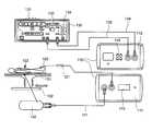
- FIG. 1Ais a schematic illustration of a first embodiment of an arrangement including an interface module according to one aspect of the present invention, including a display of the front and back panels of, and exemplary connections between, the interface module, a previously known ablation energy generator, e.g., electrosurgical generator, and an integrated catheter tip (ICT).
- ablation energy generatore.g., electrosurgical generator
- ICTintegrated catheter tip
- FIG. 1Bis a schematic illustrating exemplary connections to and from the interface module of FIG. 1A , as well as connections among other components that may be used with the interface module.
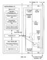
- FIG. 2Ais a schematic illustrating internal components of the interface module of FIGS. 1A-1B .
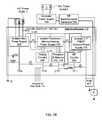
- FIG. 2Bschematically illustrates additional internal components of the interface module of FIG. 2A , as well as selected connections to and from the interface module.
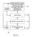
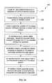
- FIG. 3Aillustrates steps in a method of using the interface module of FIGS. 1A-2B during tissue ablation.
- FIG. 3Billustrates steps in a method of calculating radiometric temperature using digital signals from a radiometer and a thermocouple and operation parameters.
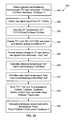
- FIG. 3Cillustrates steps in a method of controlling an ablation procedure using a temperature calculated based on signal(s) from a radiometer using the interface module of FIGS. 1A-2B .
- FIGS. 4A-4Dillustrate data obtained during exemplary ablation procedures performed using the interface module of FIGS. 1A-2B .
- FIG. 5Aillustrates a plan view of an exemplary patient interface module (PIM) associated with an integrated catheter tip (ICT) for use with the interface module of FIGS. 1A-2B .
- PIMpatient interface module
- ICTintegrated catheter tip
- FIG. 5Bschematically illustrates selected internal components of the PIM of FIG. 5A , according to some embodiments of the present invention.
- FIGS. 6A-6Brespectively illustrate perspective and exploded views of an exemplary integrated catheter tip (ICT) for use with the interface module of FIGS. 1A-2B and the PIM of FIGS. 5A-5B , according to some embodiments of the present invention.
- ICTintegrated catheter tip
- Embodiments of the present inventionprovide systems and methods for radiometrically measuring temperature during ablation, in particular cardiac ablation.
- commercially available systems for cardiac ablationmay include thermocouples for measuring temperature, but such thermocouples may not adequately provide the clinician with information about tissue temperature.
- the clinicianmay need to make an “educated guess” about whether a given region of tissue has been sufficiently ablated to achieve the desired effect.
- calculating a temperature based on signal(s) from a radiometeris expected to provide accurate information about the temperature of tissue at depth, even during an irrigated procedure.
- the present inventionprovides a “retrofit” solution that includes an interface module that works with existing, commercially available ablation energy generators, such as electrosurgical generators.
- the interface moduledisplays a tissue temperature based on signal(s) measured by a radiometer, that a clinician may use to perform ablation procedures with significantly better accuracy than can be achieved using only a thermocouple for temperature measurement.
- FIG. 1Aillustrates plan views of front panel 111 , back panel 112 , and connections to and from exemplary interface module 110 , constructed in accordance with the principles of the present invention.
- front panel 111 of interface module 110may be connected to a catheter 120 that includes patient interface module (PIM) 121 and integrated catheter tip (ICT) 122 .
- Catheter 120optionally is steerable, or may be non-steerable and used in conjunction with a robotic positioning system or a third-party steerable sheath (not shown).
- ICT 122is positioned by a clinician (optionally with mechanical assistance such as noted above), during a procedure, within subject 101 lying on grounded table 102 .
- ICT 122may include, among other things, an ablative tip, a thermocouple, and a radiometer for detecting the volumetric temperature of tissue subjected to ablation.
- the ICT 122optionally includes one or more irrigation ports, which in one embodiment may be connected directly to a commercially available irrigant pump.
- the ablative tipmay include an irrigated ablation electrode, such as described in greater detail below with reference to FIGS. 6A-6B .
- ICT 122further may include one or more electrocardiogram (ECG) electrodes for use in monitoring electrical activity of the heart of subject 101 .
- Interface module 110receives signals from the thermocouple, radiometer, and optional ECG electrodes of ICT 122 via PIM 121 .
- Interface module 110provides to ICT 122 , via PIM 121 , power for the operation of the PIM and the sensors (thermocouple, radiometer, and ECG electrodes), and ablation energy to be applied to subject 101 via the ablative tip.
- Back panel 112 of interface module 110may be connected via connection cable 135 to a commercially available previously-known ablation energy generator 130 , for example an electrosurgical generator 130 , such as a Stockert EP-Shuttle 100 Generator (Stockert GmbH, Freiburg Germany) or Stockert 70 RF Generator (Biosense Webster, Diamond Bar, Calif.).
- a commercially available previously-known ablation energy generator 130for example an electrosurgical generator 130 , such as a Stockert EP-Shuttle 100 Generator (Stockert GmbH, Freiburg Germany) or Stockert 70 RF Generator (Biosense Webster, Diamond Bar, Calif.).
- generator 130includes display device 131 for displaying temperature and the impedance and time associated with application of a dose of RF ablation energy; power control knob 132 for allowing a clinician to adjust the power of RF ablative energy delivered to subject 101 ; and start/stop/mode input for allowing a clinician to initiate or terminate the delivery of RF ablation energy.
- Start/stop/mode inputalso may be configured to control the mode of energy delivery, e.g., whether the energy is to be cut off after a given period of time.
- generator 130may be configured to display temperature on display device 131 , that temperature is based on readings from a standard thermocouple. As noted above, however, that reported temperature may be inaccurate while irrigant and ablative energy are being applied to tissue.
- Interface module 110provides to generator 130 , via connection cable 135 , a thermocouple signal for use in displaying such a temperature, and signals from the ECG electrodes; and provides via indifferent electrode cable 134 a pass-through connection to indifferent electrode 140 .
- Interface module 110receives from generator 130 , via connection cable 135 , RF ablation energy that module 110 controllably provides to ICT 122 for use in ablating tissue of subject 101 .
- a clinicianmay position an indifferent electrode (IE) on the back of subject 101 so as to provide a voltage differential that enables transmission of RF energy into the tissue of the subject.
- the IEis connected to interface module 110 via first indifferent electrode cable 141 .
- Interface module 110passes through the IE signal to second indifferent electrode cable 134 , which is connected to an indifferent electrode input port on electrosurgical generator 130 .
- the IEmay be connected directly to that port of the electrosurgical generator 130 via appropriate cabling (not shown).
- electrosurgical generators other than the Stockert EP-Shuttle or 70 RF Generatorsuitably may be used, e.g., other makes or models of RF electrosurgical generators.
- generators that produce other types of ablation energysuch as microwave generators, cryosurgical sources, or high frequency ultrasound generators, may be used.
- Ablation energy generator 130need not necessarily be commercially available, although as noted above it may be convenient to use one that is. It should also be appreciated that the connections described herein may be provided on any desired face or panel of interface module 110 , and that the functionalities of different connectors and input/output (I/O) ports may be combined or otherwise suitably modified.
- Front panel 111 of interface module 110includes temperature display 113 , e.g., a digital two or three-digit display device configured to display a temperature calculated by a processor internal to interface module 110 , e.g., as described in greater detail below with reference to FIGS. 2A-2B and 3 A.
- temperature display 113e.g., a digital two or three-digit display device configured to display a temperature calculated by a processor internal to interface module 110 , e.g., as described in greater detail below with reference to FIGS. 2A-2B and 3 A.
- Other types of temperature displayssuch multicolor liquid crystal displays (LCDs), alternatively may be used.
- Front panel 111also includes connectors (not labeled) through which interface module 110 is connected to ICT 122 via PIM 121 , and to the IE 140 via indifferent electrode cable 141 .
- Back panel 111 of interface module 110includes connectors (not labeled) through which interface module 110 is connected to electrosurgical generator 130 , via indifferent electrode cable 134 and connection cable 135 .
- Back panel 112 of interface module 110also includes data ports 114 configured to output one or more signals to a suitably programmed personal computer or other remote device, for example an EP monitoring/recording system such as the LABSYSTEMTM PRO EP Recording System (C.R. Bard, Inc., Lowell, Mass.).
- signalsmay, for example, include signals generated by the thermocouple, radiometer, and/or ECG electrodes of the ICT, the tissue temperature calculated by interface module 110 , and the like.
- interface module 110is in operable communication with catheter 120 having a patient interface module (PIM) 121 and an integrated catheter tip (ICT) 122 that includes a radiometer, ablative tip, a thermocouple (TC), and optionally also includes ECG electrodes and/or irrigation ports(s).
- PIMpatient interface module
- ICTintegrated catheter tip
- TCthermocouple
- ECG electrodes and/or irrigation ports(s)are also in operable communication with electrosurgical generator 130 and indifferent electrode 140 .
- Electrosurgical generator 130optionally is in operable communication with electrophysiology (EP) monitoring/recording system 160 via appropriate cabling.
- interface system 110may be directly connected to EP monitoring/recording module 160 via appropriate cabling and data ports 114 .
- EP monitoring/recording systemsmay include, for example, various monitors, processors, and the like that display pertinent information about an ablation procedure to a clinician, such as the subject's heart rate and blood pressure, the temperature recorded by the thermocouple on the catheter tip, the ablation power and time period over which it is applied, fluoroscopic images, and the like.
- EP monitoring/recording systemsare commercially available, e.g., the MEDELECTM Synergy T-EP—EMG/EP Monitoring System (CareFusion, San Diego, Calif.), or the LABSYSTEMTM PRO EP Recording System (C.R. Bard, Inc., Lowell, Mass.).
- irrigation pump 140associated with electrosurgical generator 130 , which pump is in operable communication with the generator and in fluidic communication with the ICT.
- irrigation pump 140associated with electrosurgical generator 130 , which pump is in operable communication with the generator and in fluidic communication with the ICT.
- the Stockert 70 RF Generatoris designed for use with a CoolFlowTM Irrigation pump, also manufactured by Biosense Webster.
- the Stockert 70 RF Generator and the CoolFlowTM pumpmay be connected to one another by a commercially available interface cable, so as to operate as an integrated system that works in substantially the same way as it would with a standard, commercially available catheter tip.
- the clinicianinstructs the pump to provide a low flow rate of irrigant to the ICT, as it would to a standard catheter tip; the ICT is then positioned in the body. Then, when the clinician presses the “start” button on the face of generator 130 , the generator may instruct pump 150 to provide a high flow rate of irrigant for a predetermined period (e.g., 5 seconds) before providing RF ablation energy, again as it would for a standard catheter tip. After the RF ablation energy application is terminated, then pump 150 returns to a low flow rate after another predetermined period (e.g., 5 seconds). The pump remains at a low flow rate until the clinician removes the ICT 122 from the body and manually turns off the pump.
- a predetermined periode.g. 5 seconds
- interface module 110 of FIGS. 1A-1Bfurther details of internal components of interface module 110 of FIGS. 1A-1B are provided.
- FIG. 2Aschematically illustrates internal components of one embodiment of interface module 110 .
- Interface module 110includes first, second, third, and fourth ports 201 - 204 by which it communicates with external components.
- first port 201is an input/output (I/O) port configured to be connected to catheter 120 via PIM 121 , as illustrated in FIG. 1A .
- Port 201receives as input from catheter 120 digital radiometer and digital thermocouple (TC) signals, and optionally ECG signals, generated by ICT 122 , and provides as output to catheter 120 RF ablation energy, as well as power for circuitry within the ICT 122 and the PIM 121 .
- Second port 202is also an I/O port, configured to be connected to electrosurgical generator 130 via connection cable 135 illustrated in FIG.
- Third port 203is an input port configured to be connected to indifferent electrode (IE) 140 via indifferent electrode cable 134 illustrated in FIG. 1A
- fourth port 204is an output port configured to be connected to generator 130 via indifferent electrode cable 141 illustrated in FIG. 1A .
- interface module 110acts as a pass-through for the IE signal from IE 140 to generator 130 , and simply receives IE signal on third port 203 and provides the IE signal to generator 130 on fourth port 204 .
- Interface module 110also includes processor 210 coupled to non-volatile (persistent) computer-readable memory 230 , user interface 280 , load relay 260 , and patient relay 250 .
- Memory 230stores programming that causes processor 210 to perform steps described further below with respect to FIGS. 3A-3C , thereby controlling the functionality of interface module 110 .
- Memory 230also stores parameters used by processor 210 .
- memory 230may store a set of operation parameters 231 for the thermocouple and radiometer, as well as a temperature calculation module 233 , that processor 210 uses to calculate the radiometric temperature based on the digital TC and radiometer signals received on first I/O port 201 , as described in greater detail below with respect to FIG. 3B .
- the operation parameters 231may be obtained through calibration, or may be fixed.
- Memory 230also stores a set of safety parameters 232 that processor 210 uses to maintain safe conditions during an ablation procedure, as described further below with respect to FIG. 3C .
- Memory 230further stores decision module 234 that processor 210 uses to control the opening and closing of patient relay 250 and load relay 260 based on its determinations of temperature and safety conditions, as described further below with reference to FIGS. 3A-3C .
- patient relay 250passes ablative energy from the second I/O port 202 to the first I/O port 201 .
- load relay 260returns ablative energy to the IE 140 via dummy load D (resistor, e.g., of 120 ⁇ resistance) and fourth I/O port 204 .
- dummy load Dresistor, e.g., of 120 ⁇ resistance
- interface module 110further includes user interface 280 by which a user may receive information about the temperature adjacent ICT 122 as calculated by processor 210 , as well as other potentially useful information.
- user interface 280includes digital temperature display 113 , which displays the instantaneous temperature calculated by processor 210 .
- display 113may be an LCD device that, in addition to displaying the instantaneous temperature calculated by processor 210 , also graphically display changes in the temperature over time for use by the clinician during the ablation procedure.
- User interface 280further may include data ports 114 , which may be connected to a computer or EP monitoring/recording system by appropriate cabling as noted above, and which may output digital or analog signals being received or generated by interface module 110 , e.g., radiometer signal(s), a thermocouple signal, and/or the temperature calculated by processor 210 .
- data ports 114may be connected to a computer or EP monitoring/recording system by appropriate cabling as noted above, and which may output digital or analog signals being received or generated by interface module 110 , e.g., radiometer signal(s), a thermocouple signal, and/or the temperature calculated by processor 210 .
- interface module 110may include opto-electronics 299 that communicate information to and from processor 210 , but that substantially inhibit transmission of RF energy to processor 210 , memory 230 , or user interface 280 .
- This isolationis designated by the dashed line in FIG. 2A .
- opto-electronics 299may include circuitry that is in operable communication with first I/O port 201 so as to receive the digital TC and radiometer signals from first I/O port 201 , and that converts such digital signals into optical digital signals.
- Opto-electronics 299also may include an optical transmitter in operable communication with such circuitry, that transmits those optical digital signals to processor 210 through free space.
- Opto-electronics 299further may include an optical receiver in operable communication with processor 210 , that receives such optical digital signals, and circuitry that converts the optical digital signals into digital signals for use by processor 210 .
- the opto-electronic circuitry in communication with the processoralso may be in operable communication with a second optical transmitter, and may receive signals from processor 210 to be transmitted across free space to an optical receiver in communication with the circuitry that receives and processes the digital TC and radiometer signals.
- processor 210may transmit to such circuitry, via an optical signal, a signal that causes the circuitry to generate an analog version of the TC signal and to provide that analog signal to the second I/O port.
- processor 210may transmit to such circuitry, via an optical signal, a signal that causes the circuitry to generate an analog version of the TC signal and to provide that analog signal to the second I/O port.
- FIG. 2Bis an exemplary schematic for a grounding and power supply scheme suitable for using interface module 110 with an RF electrosurgical generator, e.g., a Stockert EP-Shuttle or 70 RF Generator.
- RF electrosurgical generatore.g., a Stockert EP-Shuttle or 70 RF Generator.
- Other grounding and power supply schemessuitably may be used with other types, makes, or models of electrosurgical generators, as will be appreciated by those skilled in the art.
- interface module 110includes isolated main power supply 205 that may be connected to standard three-prong A/C power outlet 1 , which is grounded to mains ground G.
- Interface module 110also includes several internal grounds, designated A, B, C, and I.
- Internal ground Ais coupled to the external mains ground G via a relatively small capacitance capacitor (e.g., a 10 pF capacitor) and a relatively high resistance resistor (e.g., a 20 M ⁇ resistor) that substantially prevents internal ground A from floating.
- Internal ground Bis coupled to internal ground A via a low resistance pathway (e.g., a pathway or resistor(s) providing less than 1000 ⁇ resistance, e.g., about 0 ⁇ resistance).
- Internal ground Cis coupled to internal ground B via another low resistance pathway.
- Internal ground Iis an isolated ground that is coupled to internal ground C via a relatively small capacitance capacitor (e.g., a 10 pF capacitor) and a relatively high resistance resistor (e.g., a 20 M ⁇ resistor) that substantially prevents isolated ground I from floating.
- a relatively small capacitance capacitore.g., a 10 pF capacitor
- a relatively high resistance resistore.g., a 20 M ⁇ resistor
- Isolated main power supply 205is coupled to internal ground A via a low resistance pathway. Isolated main power supply 205 is also coupled to, and provides power (e.g., ⁇ 12V) to, one or more internal isolated power supplies that in turn provide power to components internal to interface module 110 .
- Such componentsinclude, but are not limited to components illustrated in FIG. 2A .
- interface module 110may include one or more isolated power supplies 220 that provide power (e.g., ⁇ 4V) to processor 210 , memory 230 , and analog circuitry 240 .
- Analog circuitry 240may include components of user interface 280 , including temperature display 113 and circuitry that appropriately prepares signals for output on data ports 114 .
- Interface modulealso may include one or more isolated power supplies 270 that provide power (e.g., ⁇ 4V) to ICT 122 , PIM 121 , and RF circuitry 290 .
- powere.g., ⁇ 4V
- RF circuitry 290may include patient and load relays 250 , 260 , as well as circuitry that receives the radiometer and thermocouple signals and provides such signals to the processor via optoelectronic coupling, and circuitry that generates a clock signal to be provided to the ICT as described further below with reference to FIG. 5B .
- RF circuitry 290 , ICT 122 , and PIM 121are coupled to isolated internal ground I via low resistance pathways.
- power supply 139 of RF electrosurgical generator 130which may be external to generator 130 as in FIG. 2B or may be internal to generator 130 , is connected to standard two- or three-prong A/C power outlet 2 .
- generator power supply 139is not connected to the ground of the outlet, and thus not connected to the mains ground G, as is the isolated main power supply. Instead, generator power supply 139 and RF electrosurgical generator 130 are grounded to internal isolated ground I of interface module 110 via low resistance pathways between generator 130 and PIM 121 and ICT 122 , and low resistance pathways between PIM 121 and ICT 122 and internal isolated ground I.
- RF circuitry 290 , PIM 121 , IE 140 , and generator 130are all “grounded” to an internal isolated ground I that has essentially the same potential as does ICT 122 .
- the ground of RF circuitry 290 , PIM 121 , ICT 122 , IE 140 , and generator 130all essentially float with the RF energy amplitude, which may be a sine wave of 50-100V at 500 kHz.
- the ⁇ 12V of power that isolated main power supply 205 provides to isolated processor/memory/analog power supply 220 and to isolated ICT/RF power supply 270may be coupled by parasitic capacitance (pc, approximately 13 pF) to A/C power outlet 1 , as may be the ⁇ 4V of power that such power supplies provide to their respective components.
- parasitic capacitancepc, approximately 13 pF
- Such parasitic couplingwill be familiar to those skilled in the art.
- the particular resistances, capacitances, and voltages described with reference to FIG. 2Bare purely exemplary and may be suitably varied as appropriate to different configurations.
- ICTintegrated catheter tip
- IEindifferent electrode
- ICT 122may be coupled to a first connector on front panel 111 of interface module 110 via patient interface module (PIM) 121
- IE 140may be coupled to a third connector on front panel 111 via indifferent electrode cable 141
- the first connectoris in operable communication with first I/O port 201 (see FIG. 2A ) and the third connector is in operable communication with third I/O port 203 (see FIG. 2A ).
- the clinicianmay couple the electrosurgical generator to I/O port(s) of the interface module (step 302 ).
- electrosurgical generator 130may be coupled to a second connector on back panel 112 of interface module 110 via connection cable 135 , and also may be coupled to a fourth connector on back panel 112 via indifferent electrode cable 134 .
- the second connectoris in operable communication with second I/O port 202 (see FIG. 2A )
- the fourth connectoris in operable communication with fourth I/O port 204 (see FIG. 2A ).
- the clinicianinitiates flow of irrigant, positions the ICT within the subject, e.g., in the subject's heart, and positions the IE in contact with the subject, e.g., on the subject's back (step 303 ).
- positions the ICT within the subjecte.g., in the subject's heart
- positions the IE in contact with the subjecte.g., on the subject's back
- Those skilled in the artwill be familiar with methods of appropriately positioning catheter tips relative to the heart of a subject, for example via the venous vasculature.
- the interface modulereceives digital radiometer, digital thermocouple, and/or analog ECG signals from the ICT, and receives ablation energy from the generator (step 304 ), for example using the connections, ports, and pathways described above with references to FIGS. 1A-2B .
- the generatormay provide such ablation energy to the interface module responsive to the clinician pressing “start” using inputs 133 on the front face of generator 130 (see FIG. 1A ).
- the interface modulecalculates and displays the temperature adjacent to the ICT, based on the radiometer and thermocouple signals (step 305 ). This calculation may be performed, for example, by processor 210 based on instructions in temperature calculation module 233 stored in memory 230 (see FIG. 2A ). Exemplary methods of performing such a calculation are described in greater detail below with respect to FIG. 3B .
- the interface modulealso closes the patient relay so as to provide ablation energy to the ICT for use in tissue ablation (step 306 ).
- processor 210may maintain patient relay 250 illustrated in FIG. 2A in a normally closed state during operation, such that ablation energy flows from electrosurgical generator 130 to ICT 122 through interface module 110 without delay upon the clinician's actuation of the generator, and may open patient relay 250 only upon detection of unsafe conditions such as described below with respect to FIG. 3C .
- processor 210may maintain patient relay 250 in a normally open state during operation, and may determine based on instructions in decision module 234 and on the temperature calculated in step 305 that it is safe to proceed with tissue ablation, and then close patient relay so as to pass ablation energy to the ICT. In either case, after a time period defined using input 133 on the front face of generator 130 , the supply of ablation energy ceases or the clinician manually turns off the supply of ablation energy.
- the interface modulealso generates an analog version of the thermocouple signal, and provides the ECG and analog thermocouple signals to the generator (step 307 ).
- step 307is performed continuously by the interface module throughout steps 330 through 306 , rather than just at the end of the ablation procedure.
- the Stockert EP-Shuttle or 70 RF Generatormay “expect” certain signals to function properly, e.g., those signals that the generator would receive during a standard ablation procedure that did not include use of interface module 110 .
- the Stockert EP-Shuttle or 70 RF generatorrequires as input an analog thermocouple signal, and optionally may accept analog ECG signal(s).
- the interface module 110thus may pass through the ECG signal(s) generated by the ICT to the Stockert EP-shuttle or 70 RF generator via second I/O port 202 .
- interface module 110receives a digital thermocouple signal from ICT 122 .
- the Stockert EP-Shuttle or 70 RF generatoris not configured to receive or interpret a digital thermocouple signal.
- interface module 110includes the functionality of reconstituting an analog version of the thermocouple signal, for example using processor 210 and opto-electronics 299 , and providing that analog signal to generator 130 via second I/O port 202 .
- FIG. 3Bthe steps of method 350 of calculating radiometric temperature using digital signals from a radiometer and a thermocouple and operation parameters is described.
- the steps of the methodmay be executed by processor 210 based on temperature calculation module 233 stored in memory 230 (see FIG. 2A ). While some of the signals and operation parameters discussed below are particular to a PIM and ICT configured for use with RF ablation energy, other signals and operation parameters may be suitable for use with a PIM and ICT configured for use with other types of ablation energy. Those skilled in the art will be able to modify the systems and methods provided herein for use with other types of ablation energy.
- processor 210obtains from memory 230 the operation parameters for the thermocouple (TC) and the radiometer (step 351 ).
- These operation parametersmay include, for example, TCSlope, which is the slope of the TC response with respect to temperature; TCOffset, which is the offset of the TC response with respect to temperature; RadSlope, which is the slope of the radiometer response with respect to temperature; TrefSlope, which is the slope of a reference temperature signal generated by the radiometer with respect to temperature; and F, which is a scaling factor.
- Processor 210then obtains via first I/O port 201 and opto-electronics 299 the raw digital signal from the thermocouple, TCRaw (step 352 ), and calculates the thermocouple temperature, TCT, based on TCRaw using the following equation (step 353 ):
- TCTTCRaw TCSlope - TCOffset
- processor 210causes temperature display 113 to display TCT until both of the following conditions are satisfied: TCT is in the range of 35° C. to 39° C., and ablation energy is being provided to the ICT (e.g., until step 306 of FIG. 3A ). There are several reasons to display only the thermocouple temperature TCT, as opposed to the temperature calculated based on signal(s) from the radiometer, until both of these conditions are satisfied. First, if the temperature TCT measured by the thermocouple is less than 35° C., then based on instructions in decision module 234 the processor 210 interprets that temperature as meaning that the ICT is not positioned within a living human body, which would have a temperature of approximately 37° C. If the ICT is not positioned within a living human body, then it would be unsafe to provide power to the radiometer circuitry, as it may rapidly burn out if powered on in air as opposed to blood.
- Processor 210then provides ablation energy to the ICT, e.g., in accordance with step 306 described above, and receives via second I/O port 202 two raw digital signals from the radiometer: Vrad, which is a voltage generated by the radiometer based on the temperature adjacent the ICT; and Vref, which is a reference voltage generated by the radiometer (step 355 ).
- Vradwhich is a voltage generated by the radiometer based on the temperature adjacent the ICT
- Vrefwhich is a reference voltage generated by the radiometer
- Processor 210also calculates the radiometric temperature Trad based on Vrad and Tref using the following equation (step 357 ):
- processor 210may continuously calculate TCT, and also may continuously calculate Tref and Trad during times when ablation power is provided to the ICT (which is subject to several conditions discussed further herein).
- Processor 210may store in memory 230 these values at specific times and/or continuously, and use the stored values to perform further temperature calculations.
- processor 210may store in memory 230 TCT, Tref, and Trad at baseline, as the respective values TCBase, TrefBase, and TradBase.
- the processorthen re-calculates the current radiometric temperature TradCurrent based on the current Vrad received on second I/O port 202 , but instead with reference to the baseline reference temperature TrefBase, using the following equation (step 358 ):
- interface module 110displays for the clinician's use a temperature calculated based on signal(s) from the radiometer that is based not only on voltages generated by the radiometer and its internal reference, described further below with reference to FIGS. 6A-6B , but also on temperature measured by the thermocouple.
- method 360 of controlling an ablation procedure based on a temperature calculated based on signal(s) from a radiometer, e.g., as calculated using method 350 of FIG. 3B , and also based on safety parameters 232 and decision module 234 stored in memory 230is described.
- a slow flow of irrigantis initiated through the ICT and the ICT is then positioned within the subject (step 361 ).
- the generatormay automatically initiate slow irrigant flow to the catheter tip by sending appropriate signals to a CoolFlow irrigant pumping system associated with the generator, responsive to actuation of the generator by the clinician.
- the clinicianpresses a button on the generator to start the flow of ablation energy to the ICT; this may cause the generator to initiate a high flow of irrigant to the ICT and generation of ablation energy following a 5 second delay (step 362 ).
- the interface modulepasses the ablation energy to the ICT via the patient relay, as described above with respect to step 306 of FIG. 3A .
- the cliniciandetermines the temperature of the tissue volume that is being ablated by the ablation energy (step 363 ). By comparison, temperature measured by a thermocouple alone would provide little to no useful information during this stage of the procedure.
- Interface module 110may use the calculated radiometric temperature to determine whether the ablation procedure is being performed within safety parameters.
- processor 210may obtain safety parameters 232 from memory 230 .
- these safety parametersmay include a cutoff temperature above which the ablation procedure is considered to be “unsafe” because it may result in perforation of the cardiac tissue being ablated, with potentially dire consequences.
- the cutoff temperaturemay be any suitable temperature below which one or more unsafe conditions may not occur, for example “popping” such as described below with respect to FIGS. 4C-4D , or tissue burning, but at which the tissue still may be sufficiently heated.
- a suitable cutoff temperatureis 85° C., although higher or lower cutoff temperatures may be used, e.g., 65° C., 70° C., 75° C., 80° C., 90° C., or 95° C.
- Instructions in decision module 234also stored in memory 230 , cause processor 210 to continuously compare the calculated radiometric temperature to the cutoff temperature, and if the radiometric temperature exceeds the cutoff temperature, the processor may set an alarm, open the patient relay, and close the load relay so as to return power to the IE via I/O port 204 , thereby cutting off flow of ablation energy to the ICT (step 364 of FIG. 3C ). Otherwise, the processor may allow the ablation procedure to proceed (step 364 ).
- the ablation procedureterminates (step 365 ), for example, when the clinician presses the appropriate button on generator 130 , or when the generator 130 automatically cuts of ablation energy at the end of a predetermined period of time.
- FIGS. 4A-4Billustrative data obtained during an ablation experiment using an interface module constructed in accordance with the present invention is described.
- This datawas obtained using an unmodified Stockert EP Shuttle Generator with integrated irrigation pump, and a catheter including the PIM 121 and ICT 122 described further below with reference to FIGS. 5A-6B coupled to interface module 110 .
- the ICTwas placed against exposed thigh tissue of a living dog, and the Stockert EP Shuttle generator actuated so as to apply 20W of RF energy for 60 seconds.
- a Luxtron probewas also inserted at a depth of 3 mm into the dog's thigh.
- Luxtron probesare considered to provide accurate temperature information, but are impractical for normal use in cardiac ablation procedures because such probes cannot be placed in the heart of a living being.
- FIG. 4Aillustrates the change over time in various signals collected during the ablation procedure.
- Signal 410corresponds to scaled radiometric temperature TSrad;
- signal 420corresponds to the thermocouple temperature;
- signal 430corresponds to a temperature measured by the Luxtron probe; and
- signal 440corresponds to the power generated by the Stockert EP Shuttle Generator.
- Radiometric temperature signal 410indicates a sharp rise in temperature beginning at about 40 seconds, from a baseline in region 411 of about 28° C. to a maximum in region 412 of about 67° C., followed by a gradual fall in region 413 beginning around 100 seconds.
- the features of radiometric temperature signal 410are similar to those of Luxtron probe signal 430 , which similarly shows a temperature increase beginning around 40 seconds to a maximum value just before 100 seconds, and then a temperature decrease beginning around 100 seconds. This similarity indicates that the radiometric temperature has similar accuracy to that of the Luxtron probe.
- thermocouple signal 420shows a significantly smaller temperature increase beginning around 40 seconds, followed by a low-level plateau in the 40-100 second region, and then a decrease beginning around 100 seconds.
- the relatively weak response of the thermocouple, and the relatively strong and accurate response of the Luxtron thermocouple,indicate that an unmodified Stockert EP Shuttle Generator successfully may be retrofit using interface module 110 constructed in accordance with the principles of the present invention to provide a clinician with useful radiometric temperature information for use in an ablation procedure.
- FIG. 4Billustrates signals obtained during a similar experimental procedure, but in which two Luxtron probes were implanted into the animal's tissue, the first at a depth of 3 mm and the second at a depth of 7 mm.
- the Stockert EP Shuttle generatorwas activated, and the RF power was manually modulated between 5 and 50 W using the power control knob on the front panel of the generator.
- the radiometer signalis designated 460
- the 3 mm Luxtron designated 470the 3 mm Luxtron designated 470
- the 7 mm Luxtrondesignated 480 .
- the radiometer and 3 mm Luxtron signals 460 , 470may be seen to have relatively similar changes in amplitude to one another resulting from the periodic heating of the tissue by RF energy.
- the 7 mm Luxtron signal 480may be seen to have a slight periodicity, but far less modulation than do the radiometer and 3 mm Luxtron signals 460 , 470 . This is because the 7 mm Luxtron is sufficiently deep within the tissue that ablation energy substantially does not directly penetrate at that depth. Instead, the tissue at 7 mm may be seen to slowly warm as a function of time, as heat deposited in shallower portions of the tissue gradually diffuses to a depth of 7 mm.
- a series of cardiac ablation procedureswere also performed in living humans using the experimental setup described above with respect to FIGS. 4A-4B , but omitting the Luxtron probes.
- the humansall suffered from atrial flutter, were scheduled for conventional cardiac ablation procedures for the treatment of same, and consented to the clinician's use of the interface box and ICT during the procedures.
- the procedureswere performed by a clinician who introduced the ICT into the individuals' endocardia using conventional methods.
- the clinicianwas not allowed to view the temperature calculated by the interface module.
- the clinicianperformed the procedures in the same manner as they would have done with a system including a conventional RF ablation catheter directly connected to a Stockert EP-Shuttle generator.
- the temperature calculated by the interface module during the various procedureswas made available for the clinician to review at a later time.
- the clinicianperformed a total of 113 ablation procedures on five humans using the above-noted experimental setup.
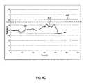
- FIGS. 4C-4Dillustrate data obtained during sequential ablation procedures performed on a single individual using the experimental setup. Specifically, FIG. 4C illustrates the change over time in the signal 415 corresponding to the scaled radiometric temperature TSrad, as well as the change over time in the signal 421 corresponding to the thermocouple temperature, during the tenth ablation procedure performed on the individual.
- about 40 W of RF powerwas applied to the individual's cardiac tissue for 60 seconds (between about 20 seconds and 80 seconds in FIG. 4C ), and the clinician had a target temperature 445 of 55° C. to which it was desired to heat the cardiac tissue so as to sufficiently interrupt an aberrant pathway causing the individual's atrial flutter.
- the scaled radiometric temperature signal 415which was subjected to data smoothing in FIG. 4C , varied between about 40° C. and 51° C. while RF power was applied.
- the thermocouple temperature 421provided essentially no useful information about the tissue temperature during the procedure.
- the clinician's target temperature 445 of 55° C.was never reached during the procedure, even though the clinician believed based on his or her perceptions of the procedure that such temperature had been reached. Because the target temperature 445 was not reached, the tissue was insufficiently heated during the procedure to interrupt an aberrant pathway. The failure to reach the target temperature may be attributed to insufficient contact or force between the ablative tip of the ICT and the individual's cardiac tissue, the condition of the cardiac surface, insufficient power, and the like.
- FIG. 4Dillustrates the change over time in signal 416 corresponding to TSrad, as well as the change over time in the signal 422 corresponding to the thermocouple temperature, during the eleventh ablation procedure performed on the same individual as in FIG. 4C .
- this procedureagain about 40W of RF power was applied to the individual's cardiac tissue for 60 seconds (between about 20 seconds and 80 seconds in FIG. 4D ), and the clinician again had a target temperature 445 of 55° C.
- the scaled radiometric signal 416again subject to data smoothing, varied between about 55° C. and 70° C. while RF power was applied, while the thermocouple temperature 421 again provided essentially no useful information.
- the clinicianattributed the higher temperature tissue temperature achieved during the ablation to better contact between the ablative tip of the ICT and the individual's cardiac tissue.
- the temperaturevaried relatively rapidly over time, e.g., from about 70° C. at about 35 seconds, to about 56° C. at 40 seconds, which may be attributed to variations in the quality of contact between the ICT and the individual's cardiac tissue.
- the cutoff temperaturewas defined to be 95° C.
- a “pop”occurs when the blood boils because of excessive localized heating caused by ablation energy, which results in formation of a rapidly expanding bubble of hot gas that may cause catastrophic damage to the cardiac tissue. It is believed that a lower cutoff temperature, e.g., 85° C., may inhibit formation of such “pops.”
- interface module 110 of the present inventione.g., PIM 121 and ICT 122 of catheter 120 .
- PIM 121patient interface module (PIM) 121 that may be associated with the integrated catheter tip (ICT) described further below with respect to FIGS. 6A-6B is described.
- PIM 121includes interface module connector 501 that may be connected to front panel 111 of interface module 110 , as described with reference to FIG. 1A ; PIM circuitry 502 , which will be described in greater detail below with reference to FIG. 5B ; ICT connector 503 that may be connected to catheter 120 ; and PIM cable 504 that extends between interface module connector 501 and PIM circuitry 502 .
- PIM 121is preferably, but not necessarily, designed to remain outside the sterile field during the ablation procedure, and optionally is reusable with multiple ICT's.
- FIG. 5Bschematically illustrates internal components of PIM circuitry 502 , and includes first I/O port 505 configured to be coupled to catheter 120 , e.g., via ICT connector 503 , and second I/O port 506 configured to be coupled to interface module 110 , e.g., via PIM cable 504 and interface module connector 501 .
- PIM circuitry 502receives on first I/O port 505 an analog thermocouple (TC) signal, raw analog radiometer signals, and analog ECG signals from catheter 120 .
- PIM circuitry 502includes TC signal analog-to-digital (A/D) converter 540 that is configured to convert the analog TC signal to a digital TC signal, and provide the digital TC signal to interface module 110 via second I/O port 506 .
- PIM circuitry 502includes a series of components configured to convert the raw analog radiometer signals into a usable digital form.
- PIM circuitrymay include radiometric signal filter 510 configured to filter residual RF energy from the raw analog radiometer signals; radiometric signal decoder 520 configured to decode the filtered signals into analog versions of the Vref and Vrad signals mentioned above with reference to FIG. 3B ; and radiometric signal A/D converter 530 configured to convert the analog Vref, Vrad signals into digital Vref, Vrad signals and to provide those digital signals to second I/O port for transmission to interface module 110 .
- PIM circuitry 502also passes through the ECG signals to second I/O port 506 for transmission to interface module 110 .
- PIM circuitry 502receives RF ablation energy from generator 130 (e.g., a Stockert EP-Shuttle or 70 RF Generator) via interface module 110 . PIM circuitry 502 passes that RF ablation energy through to catheter 120 via first I/O port 505 . PIM circuitry 502 also receives on second I/O port 506 a clock signal generated by RF circuitry within interface module 110 , as described further above with reference to FIG. 2B , and passes through the clock signal to first I/O port 505 for use in controlling microwave circuitry in ICT 122 , as described below.
- generator 130e.g., a Stockert EP-Shuttle or 70 RF Generator
- ICTintegrated catheter tip
- FIGS. 6A-6Ban exemplary integrated catheter tip (ICT) 122 for use with the interface module 110 of FIGS. 1A-2B and the PIM of FIGS. 5A-5B is described. Further detail on components of ICT 122 may be found in U.S. Pat. No. 7,769,469 to Carr, the entire contents of which are incorporated herein by reference, as well as in U.S. Patent Publication No. 2010/0076424, also to Can (“the Can publication”), the entire contents of which are incorporated herein by reference.
- the device described in the aforementioned patent and publicationdo not include a thermocouple or ECG electrodes, which preferably are included in ICT 122 configured for use with interface module 110 .
- ICT 122includes an inner or center conductor 103 supported by a conductive carrier or insert 104 .
- Carrier 104may be formed from a cylindrical metal body having an axial passage 106 that receives conductor 103 . Upper and lower sectors of that body extending inward from the ends may be milled away to expose passage 106 and conductor 103 therein and to form upper and lower substantially parallel flats 108 a and 108 b .
- Flat 108 amay include coplanar rectangular areas 108 aa spaced on opposite sides of conductor 103 near the top thereof.
- flat 108 bmay include two coplanar rectangular areas 108 bb spaced on opposite sides of conductor 103 near the bottom thereof.
- carrier 104may include center segment 104 a containing the flats and distal and proximal end segments 104 b and 104 c , respectively, which remain cylindrical, except that a vertical groove 107 may be formed in proximal segment 104 c.
- Center conductor 103may be fixed coaxially within passage 106 by means of an electrically insulating collar or bushing 109 , e.g. of PTFE, press fit into passage 106 at distal end segment 104 b of the carrier and by a weld to the passage wall or by an electrically conductive collar or bushing (not shown) at the carrier proximal segment 104 c .
- Thiscauses a short circuit between conductor 103 and carrier 104 at the proximal end of the carrier, while an open circuit may be present therebetween at the distal end of the carrier.
- the walls 106 a of passage 106may be spaced from center conductor 103 .
- Conductor 103includes distal end segment 103 a which extends beyond the distal end of carrier 104 a selected distance, and a proximal end segment 103 b which extends from the proximal end of ICT 122 and connects to the center conductor of cable 105 configured to connect to PIM 121 .
- each plate 115 a , 115 bmay include a thin, e.g. 0.005 in., substrate 116 formed of an electrically insulating material having a high dielectric constant.
- Printed, plated or otherwise formed on the opposing or facing surfaces of substrates 116are axially centered, lengthwise conductive strips 117 , preferably 0.013-0.016 mm wide, which extend the entire lengths of substrates 116 .
- the opposite or away-facing surfaces of substrates 116are plated with conductive layers 118 , e.g. of gold. The side edges of layers 118 wrap around the side edges of the substrates.
- plate 115 aWhen the ICT is being assembled, plate 115 a may be seated on the upper flat 108 a of carrier 104 and the lower plate 115 b is likewise seated on the lower flat 108 b so that the center conductor 103 is contacted from above and below by the conductive strips 117 of the upper and lower plates and the layer 118 side edges of those plates contact carrier segment 104 a .
- a suitable conductive epoxy or cementmay be applied between those contacting surfaces to secure the plates in place.
- At least one of the platesfunctions also as a support surface for one or more monolithic integrated circuit chips (MMICs), e.g. chips 122 and 124 .
- the chip(s)may include a coupling capacitor connected by a lead (not shown) to center conductor 103 and the usual components of a radiometer such as a Dicke switch, a noise source to provide a reference temperature, amplifier stages, a band pass filter to establish the radiometer bandwidth, additional gain stages if needed, a detector and buffer amplifier. Due to the relatively small profile of the present ICT 122 , the above circuit components may be arranged in a string of four chips.
- the chip(s)may be secured to the metal layer 118 of plate 115 a by a suitable conductive adhesive so that that layer which, as described above, is grounded to the insert 104 may function as a ground plane for those chips.
- the platesalso conduct heat away from the chips to conductor 103 and carrier 104 .
- Various leads(not shown) connect the chips to each other and other leads 125 b extend through carrier slot 107 and connect the last chip 124 in the string, i.e. the radiometer output, to corresponding conductors of cable 105 leading to PIM 121 .
- a tubular outer conductor 126may be slid onto carrier 104 from an end thereof so that it snugly engages around the carrier with its proximal and distal ends coinciding with the corresponding ends of the carrier (not shown).
- the conductor 126may be fixed in place by a conductive epoxy or cement applied around the carrier segments 104 b and 104 c.
- ICT 122also may include an annular dielectric spacer 137 , e.g. of PTFE, which is centered on the distal end of carrier 104 and surrounds the conductor segment 103 a .
- the spacermay have a slit 137 a enabling it to be engaged around that conductor segment from the side thereof.
- the spacer 137may be held in place by a conductive collar 136 which encircles the spacer and is long enough to slidably engage over a distal end segment of outer conductor 126 .
- the collar 136may be press fit around that conductor and carrier segment 104 b to hold it in place and to electrically connect all those elements.
- the distal end of the ICT 122may be closed off by conductive tip 142 which, in axial section, may be T shaped. That is, the tip 142 may have discoid head 142 a that forms the distal end of the ICT and an axially extending tubular neck 142 b .
- the conductor segment 103 ais sufficiently long to extend beyond the distal end of the spacer 137 into the axial passage in neck 104 b .
- the tipmay be secured in place by conductive adhesive applied around the distal end of conductor segment 103 a and at the distal end or edge of collar 136 . When the tip is in place, the conductor segment 103 a and tip 104 form a radiometric receiving antenna, as described in greater detail in U.S. Pat. No. 7,769,469 and U.S. Patent Publication No. 2010/0076424.
- ICT 122may further include dielectric sheath 144 which may be engaged over the rear end of outer conductor 126 and slid forwardly until its distal end 144 a is spaced a selected distance behind the distal end of tip 142 .
- the conductors 103 and 126 of ICT 122form an RF transmission line terminated by the tip 104 .
- the transmission linemay radiate energy for heating tissue only from the uninsulated segment of the probe between tip 104 and the distal end 144 a of the sheath 144 . That segment thus constitutes an RF ablation antenna.
- the proximal ends of the center conductor segment 103 b , outer conductor 126 and sheath 144may be connected, respectively, to the inner and outer conductors and outer sheath of cable 105 that leads to PIM 121 .
- those elementsmay be extensions of the corresponding components of cable 105 .
- that cable 105connects the center conductor 103 to the output of a transmitter which transmits a RF heating signal at a selected heating frequency, e.g. 500 GHz, to the RF ablation antenna.
- ICT 122further may include first, second, and third ECG electrodes 190 disposed on the outside of sheath 144 , as well as a thermocouple 191 positioned so as to detect the temperature of blood or tissue in contact with ICT 122 . Signals generated by electrodes 190 and thermocouple 191 may be provided along cable 105 connected to PIM 121 .
- cable 105further may include probe steering wire 145 whose leading end 145 a may be secured to the wall of a passage 146 in carrier segment 104 c.
- helical through slot 147is provided in collar 136 as shown in FIGS. 6A-6B .
- the collar material left between the slotturns essentially forms helical wire 148 that bridges spacer 137 .
- Wire 148is found to improve the microwave antenna pattern of the radiometric receiving antenna without materially degrading the RF heating pattern of the RF ablation antenna.
- the inner or center conductor 103may be a solid wire, or preferably is formed as a tube that enables conductor 103 to carry an irrigation fluid or coolant to the interior of probe tip 142 for distribution therefrom through radial passages 155 in tip head 142 a that communicate with the distal end of the axial passage in tip neck 142 b.
- conductive strips 117 , 117 of those membersmay be electrically connected to center conductor 103 at the top and bottom thereof so that conductor 103 forms the center conducts for of a slab-type transmission line whose ground plane includes layers 118 , 118 .
- a microwave fieldexists within the substrate 116 and is concentrated between the center conductor 103 and layers 118 , 118 .
- conductive epoxyis applied between conductor 103 and strips 117 to ensure that no air gaps exist there because such a gap would have a significant effect on the impedance of the transmission line as the highest field parts are closest to conductor 103 .
- Plates 115 a , 115 b and conductor 103 segment together with carrier 104form a quarter wave ( ⁇ R /4) stub S that may be tuned to the frequency of radiometer circuit 124 , e.g. 4 GHz.
- the quarter wave stub Smay be tuned to the center frequency of the radiometer circuit along with components in chips 122 , 124 to form a low pass filter in the signal transmitting path to the RF ablation antenna, while other components of the chips form a high pass or band pass filter in the signal receiving path from the antenna to the radiometer.
- the combinationforms a passive diplexer D which prevents the lower frequency transmitter signals on the signal transmitting path from antenna T from reaching the radiometer, while isolating the path to the transmitter from the higher frequency signals on the signal receiving path from the antenna.
- the impedance of the quarter wave stub Sdepends upon the K value and thickness t of substrates 116 of the two plates 115 a , 115 b and the spacing of center conductor 103 from the walls 106 a , 106 a of passage 106 in the carrier center segment 104 a . Because the center conductor 103 is not surrounded by a ceramic sleeve, those walls can be moved closer to the center conductor, enabling accurate tuning of the suspended substrate transmission line impedance while minimizing the overall diameter of the ICT 122 . As noted above, the length of the stub S may also be reduced by making substrate 116 of a dielectric material which has a relatively high K value.
- the components of the ICThave the following dimensions:
- the overall length and diameter of the ICT 122may be relatively small, which is a useful feature for devices configured for percutaneous use.
- the interface modulehas primarily been described with reference for use with an RF electrosurgical generator and the PIM and ICT illustrated in FIGS. 5A-6B , it should be understood that the interface module suitably may be adapted for use with other sources of ablation energy and other types of radiometers.
- the radiometermay have components in the ICT and/or the PIM, and need not necessarily be located entirely in the ICT.
- the functionality of the radiometer, ICT, and/or PIMoptionally may be included in the interface module.
Landscapes
- Health & Medical Sciences (AREA)
- Life Sciences & Earth Sciences (AREA)
- Surgery (AREA)
- Engineering & Computer Science (AREA)
- General Health & Medical Sciences (AREA)
- Public Health (AREA)
- Biomedical Technology (AREA)
- Heart & Thoracic Surgery (AREA)
- Medical Informatics (AREA)
- Molecular Biology (AREA)
- Veterinary Medicine (AREA)
- Animal Behavior & Ethology (AREA)
- Nuclear Medicine, Radiotherapy & Molecular Imaging (AREA)
- Physics & Mathematics (AREA)
- Otolaryngology (AREA)
- Plasma & Fusion (AREA)
- Cardiology (AREA)
- Biophysics (AREA)
- Pathology (AREA)
- Electromagnetism (AREA)
- Surgical Instruments (AREA)
Abstract
Description
TSrad=TCBase+(TradCurrent−TradBase)×F
| Total | % of Total Ablation | |
| Number of | 5 | |
| Number of | 113 | |
| Number of ablations that did | 50 | 44% |
| not reach target temperature of | ||
| 55° C. | ||
| Number of ablations that | 13 | 12% |
| reached high temperature | ||
| cutoff of 95° C. | ||
| Number of pops | 3 | 3% |
| Number of successful | 5 | 100% |
| treatments of atrial flutter | ||
| Component | Dimension (inches) |
| 0.020 outer diameter | |
| 0.016 inner diameter (if hollow) | |
| Substrate 116 (K = 9.8) | 0.065 wide; thickness t = 0.005 |
| 0.015 wide | |
| Air gap between 103 and each 106a | 0.015 |
Claims (20)
Priority Applications (8)
| Application Number | Priority Date | Filing Date | Title |
|---|---|---|---|
| US13/368,112US8926605B2 (en) | 2012-02-07 | 2012-02-07 | Systems and methods for radiometrically measuring temperature during tissue ablation |
| EP13706127.1AEP2811931A1 (en) | 2012-02-07 | 2013-02-06 | Systems and methods for radiometrically measuring temperature during tissue ablation |
| PCT/US2013/024871WO2013119620A1 (en) | 2012-02-07 | 2013-02-06 | Systems and methods for radiometrically measuring temperature during tissue ablation |
| AU2013217304AAU2013217304A1 (en) | 2012-02-07 | 2013-02-06 | Systems and methods for radiometrically measuring temperature during tissue ablation |
| US14/274,407US8932284B2 (en) | 2012-02-07 | 2014-05-09 | Methods of determining tissue temperatures in energy delivery procedures |
| US14/285,337US9277961B2 (en) | 2009-06-12 | 2014-05-22 | Systems and methods of radiometrically determining a hot-spot temperature of tissue being treated |
| US14/593,314US20150342676A1 (en) | 2012-02-07 | 2015-01-09 | Systems and methods of measuring temperature of tissue during an ablation procedure |
| US15/063,380US20160324567A1 (en) | 2009-06-12 | 2016-03-07 | Methods of radiometrically determining an extreme temperature during a treatment procedure |
Applications Claiming Priority (1)
| Application Number | Priority Date | Filing Date | Title |
|---|---|---|---|
| US13/368,112US8926605B2 (en) | 2012-02-07 | 2012-02-07 | Systems and methods for radiometrically measuring temperature during tissue ablation |
Related Child Applications (1)
| Application Number | Title | Priority Date | Filing Date |
|---|---|---|---|
| US14/274,407ContinuationUS8932284B2 (en) | 2012-02-07 | 2014-05-09 | Methods of determining tissue temperatures in energy delivery procedures |
Publications (2)
| Publication Number | Publication Date |
|---|---|
| US20130204240A1 US20130204240A1 (en) | 2013-08-08 |
| US8926605B2true US8926605B2 (en) | 2015-01-06 |
Family
ID=47750054
Family Applications (3)
| Application Number | Title | Priority Date | Filing Date |
|---|---|---|---|
| US13/368,112Active2033-03-05US8926605B2 (en) | 2009-06-12 | 2012-02-07 | Systems and methods for radiometrically measuring temperature during tissue ablation |
| US14/274,407ActiveUS8932284B2 (en) | 2012-02-07 | 2014-05-09 | Methods of determining tissue temperatures in energy delivery procedures |
| US14/593,314AbandonedUS20150342676A1 (en) | 2012-02-07 | 2015-01-09 | Systems and methods of measuring temperature of tissue during an ablation procedure |
Family Applications After (2)
| Application Number | Title | Priority Date | Filing Date |
|---|---|---|---|
| US14/274,407ActiveUS8932284B2 (en) | 2012-02-07 | 2014-05-09 | Methods of determining tissue temperatures in energy delivery procedures |
| US14/593,314AbandonedUS20150342676A1 (en) | 2012-02-07 | 2015-01-09 | Systems and methods of measuring temperature of tissue during an ablation procedure |
Country Status (4)
| Country | Link |
|---|---|
| US (3) | US8926605B2 (en) |
| EP (1) | EP2811931A1 (en) |
| AU (1) | AU2013217304A1 (en) |
| WO (1) | WO2013119620A1 (en) |
Cited By (30)
| Publication number | Priority date | Publication date | Assignee | Title |
|---|---|---|---|---|
| US20130272339A1 (en)* | 2012-04-17 | 2013-10-17 | Penn State Research Foundation | System and method for combined microwave heating and radiometry for characterizing biological tissues |
| US9226791B2 (en) | 2012-03-12 | 2016-01-05 | Advanced Cardiac Therapeutics, Inc. | Systems for temperature-controlled ablation using radiometric feedback |
| US9277961B2 (en) | 2009-06-12 | 2016-03-08 | Advanced Cardiac Therapeutics, Inc. | Systems and methods of radiometrically determining a hot-spot temperature of tissue being treated |
| US9510905B2 (en) | 2014-11-19 | 2016-12-06 | Advanced Cardiac Therapeutics, Inc. | Systems and methods for high-resolution mapping of tissue |
| US9510909B2 (en) | 2009-08-13 | 2016-12-06 | Monteris Medical Corporation | Image-guide therapy of a tissue |
| US9517103B2 (en) | 2014-11-19 | 2016-12-13 | Advanced Cardiac Therapeutics, Inc. | Medical instruments with multiple temperature sensors |
| US9636164B2 (en) | 2015-03-25 | 2017-05-02 | Advanced Cardiac Therapeutics, Inc. | Contact sensing systems and methods |
| US20180042667A1 (en)* | 2015-01-28 | 2018-02-15 | St. Jude Medical, Cardiology Division, Inc. | Thermal mapping catheter |
| US9993178B2 (en) | 2016-03-15 | 2018-06-12 | Epix Therapeutics, Inc. | Methods of determining catheter orientation |
| US10166062B2 (en) | 2014-11-19 | 2019-01-01 | Epix Therapeutics, Inc. | High-resolution mapping of tissue with pacing |
| US10327830B2 (en)* | 2015-04-01 | 2019-06-25 | Monteris Medical Corporation | Cryotherapy, thermal therapy, temperature modulation therapy, and probe apparatus therefor |
| US10368936B2 (en) | 2014-11-17 | 2019-08-06 | Kardium Inc. | Systems and methods for selecting, activating, or selecting and activating transducers |
| US10470826B2 (en) | 2012-05-21 | 2019-11-12 | Kardium Inc. | Systems and methods for selecting, activating, or selecting and activating transducers |
| US10478254B2 (en) | 2016-05-16 | 2019-11-19 | Covidien Lp | System and method to access lung tissue |
| WO2019231936A1 (en) | 2018-05-31 | 2019-12-05 | BH Scientific, LLC | System for microwave ablation and measuring temperature during ablation |
| US10499986B2 (en) | 2007-11-16 | 2019-12-10 | Kardium Inc. | Medical device for use in bodily lumens, for example an atrium |
| US10548666B2 (en) | 2015-11-17 | 2020-02-04 | Covidien Lp | Systems and methods for ultrasound image-guided ablation antenna placement |
| US10568576B2 (en) | 2012-05-21 | 2020-02-25 | Kardium Inc. | Systems and methods for activating transducers |
| US10660691B2 (en) | 2015-10-07 | 2020-05-26 | Angiodynamics, Inc. | Multiple use subassembly with integrated fluid delivery system for use with single or dual-lumen peristaltic tubing |
| US10722184B2 (en) | 2014-11-17 | 2020-07-28 | Kardium Inc. | Systems and methods for selecting, activating, or selecting and activating transducers |
| US10820941B2 (en) | 2006-06-28 | 2020-11-03 | Kardium Inc. | Apparatus and method for intra-cardiac mapping and ablation |
| US10827977B2 (en) | 2012-05-21 | 2020-11-10 | Kardium Inc. | Systems and methods for activating transducers |
| US10888373B2 (en) | 2017-04-27 | 2021-01-12 | Epix Therapeutics, Inc. | Contact assessment between an ablation catheter and tissue |
| WO2021152508A1 (en) | 2020-01-31 | 2021-08-05 | Hepta Medical SAS | Systems and methods for tissue ablation and measurements relating to the same |
| US11219489B2 (en) | 2017-10-31 | 2022-01-11 | Covidien Lp | Devices and systems for providing sensors in parallel with medical tools |
| US11389232B2 (en) | 2006-06-28 | 2022-07-19 | Kardium Inc. | Apparatus and method for intra-cardiac mapping and ablation |
| US11666372B2 (en) | 2019-05-09 | 2023-06-06 | Gyrus Acmi, Inc. | Alternate power correction outputs in electrosurgical systems |
| WO2025094089A1 (en) | 2023-10-31 | 2025-05-08 | Hepta Medical SAS | Systems for adaptive ablation volume prediction based on tissue temperature measurements and anatomical segmentation |
| USD1084316S1 (en) | 2023-11-20 | 2025-07-15 | Angiodynamics, Inc. | Ferrule |
| US12440262B2 (en) | 2023-06-21 | 2025-10-14 | Gyrus Acmi, Inc. | Power-controlled waveform in electrosurgical systems |
Families Citing this family (23)
| Publication number | Priority date | Publication date | Assignee | Title |
|---|---|---|---|---|
| US8361067B2 (en) | 2002-09-30 | 2013-01-29 | Relievant Medsystems, Inc. | Methods of therapeutically heating a vertebral body to treat back pain |
| CA2737374C (en) | 2008-09-26 | 2017-03-28 | Relievant Medsystems, Inc. | Systems and methods for navigating an instrument through bone |
| US10028753B2 (en) | 2008-09-26 | 2018-07-24 | Relievant Medsystems, Inc. | Spine treatment kits |
| US8954161B2 (en) | 2012-06-01 | 2015-02-10 | Advanced Cardiac Therapeutics, Inc. | Systems and methods for radiometrically measuring temperature and detecting tissue contact prior to and during tissue ablation |
| US8926605B2 (en) | 2012-02-07 | 2015-01-06 | Advanced Cardiac Therapeutics, Inc. | Systems and methods for radiometrically measuring temperature during tissue ablation |
| AU2012362524B2 (en) | 2011-12-30 | 2018-12-13 | Relievant Medsystems, Inc. | Systems and methods for treating back pain |
| CN104507408B (en) | 2012-06-22 | 2017-06-20 | 柯惠有限合伙公司 | For the microwave thermometric of microwave ablation system |
| US10588691B2 (en) | 2012-09-12 | 2020-03-17 | Relievant Medsystems, Inc. | Radiofrequency ablation of tissue within a vertebral body |
| WO2014071161A1 (en) | 2012-11-05 | 2014-05-08 | Relievant Medsystems, Inc. | System and methods for creating curved paths through bone and modulating nerves within the bone |
| US9724151B2 (en) | 2013-08-08 | 2017-08-08 | Relievant Medsystems, Inc. | Modulating nerves within bone using bone fasteners |
| WO2015042173A1 (en)* | 2013-09-20 | 2015-03-26 | Advanced Cardiac Therapeutics, Inc. | Temperature sensing and tissue ablation using a plurality of electrodes |
| US10682175B2 (en)* | 2013-11-06 | 2020-06-16 | Biosense Webster (Israel) Ltd. | Using catheter position and temperature measurement to detect movement from ablation point |
| US20170172655A1 (en)* | 2014-03-21 | 2017-06-22 | Steven D. Schwaitzberg | System and method for treatment of barrett's esophagus incorporating radiometric sensing |
| US20160030111A1 (en)* | 2014-07-31 | 2016-02-04 | Covidien Lp | Systems and methods for in situ quantification of a thermal environment |
| WO2016081602A1 (en) | 2014-11-19 | 2016-05-26 | Advanced Cardiac Therapeutics, Inc. | Radiometric tissue contact and tissue type detection |
| EP3240611B1 (en) | 2014-12-30 | 2020-09-30 | Koninklijke Philips N.V. | Patient-specific ultrasound thermal strain-to-temperature calibration |
| ITUB20155021A1 (en)* | 2015-11-03 | 2017-05-03 | Fiab S P A | Device for monitoring the optimized esophageal temperature |
| US11006887B2 (en)* | 2016-01-14 | 2021-05-18 | Biosense Webster (Israel) Ltd. | Region of interest focal source detection using comparisons of R-S wave magnitudes and LATs of RS complexes |
| US10624554B2 (en) | 2016-01-14 | 2020-04-21 | Biosense Webster (Israel) Ltd. | Non-overlapping loop-type or spline-type catheter to determine activation source direction and activation source type |
| AU2020346827A1 (en) | 2019-09-12 | 2022-03-31 | Relievant Medsystems, Inc. | Systems and methods for tissue modulation |
| US12082876B1 (en) | 2020-09-28 | 2024-09-10 | Relievant Medsystems, Inc. | Introducer drill |
| EP4268150A4 (en) | 2020-12-22 | 2024-12-18 | Relievant Medsystems, Inc. | PREDICTION OF CANDIDATES FOR SPINAL NEUROMODULATION |
| US12433668B1 (en) | 2021-11-08 | 2025-10-07 | Relievant Medsystems, Inc. | Impedance stoppage mitigation during radiofrequency tissue ablation procedures |
Citations (275)
| Publication number | Priority date | Publication date | Assignee | Title |
|---|---|---|---|---|
| US4190053A (en) | 1977-06-20 | 1980-02-26 | Rca Corporation | Apparatus and method for hyperthermia treatment |
| US4197860A (en) | 1977-11-21 | 1980-04-15 | Rca Corporation | Hyperthermia applicator |
| US4346716A (en) | 1980-03-31 | 1982-08-31 | M/A Com, Inc. | Microwave detection system |
| US4557272A (en) | 1980-03-31 | 1985-12-10 | Microwave Associates, Inc. | Microwave endoscope detection and treatment system |
| US4632127A (en) | 1985-06-17 | 1986-12-30 | Rca Corporation | Scanning microwave hyperthermia with feedback temperature control |
| US4647281A (en) | 1985-02-20 | 1987-03-03 | M/A-Com, Inc. | Infiltration detection apparatus |
| US4715727A (en) | 1984-07-05 | 1987-12-29 | M/A-Com, Inc. | Non-invasive temperature monitor |
| US4774961A (en) | 1985-11-07 | 1988-10-04 | M/A Com, Inc. | Multiple antennae breast screening system |
| US4815479A (en) | 1986-08-13 | 1989-03-28 | M/A Com, Inc. | Hyperthermia treatment method and apparatus |
| US4945912A (en) | 1988-11-25 | 1990-08-07 | Sensor Electronics, Inc. | Catheter with radiofrequency heating applicator |
| US5073167A (en) | 1987-06-26 | 1991-12-17 | M/A-Com, Inc. | In-line microwave warming apparatus |
| US5105808A (en) | 1988-09-09 | 1992-04-21 | Gynelab Products | Intrauterine cauterizing method |
| US5149198A (en) | 1991-05-02 | 1992-09-22 | Mmtc, Inc. | Temperature-measuring microwave radiometer apparatus |
| US5176146A (en) | 1989-07-27 | 1993-01-05 | Institut National De La Sante Et De La Recherche Medicale | Method for the measurement of temperatures by microwave radiometry, with automatic calibration of the measurement, and device for operating this method |
| US5198776A (en) | 1991-06-26 | 1993-03-30 | Microwave Medical Systems, Inc. | Microwave system for detecting gaseous emboli |
| US5334141A (en) | 1992-06-26 | 1994-08-02 | Medrad, Inc. | Extravasation detection system and apparatus |
| US5344435A (en) | 1988-07-28 | 1994-09-06 | Bsd Medical Corporation | Urethral inserted applicator prostate hyperthermia |
| US5354325A (en) | 1991-07-26 | 1994-10-11 | Institut National De La Sante Et De La Recherche Medicale | System for internal heat treatment of a specific body and its use |
| US5364336A (en) | 1990-12-17 | 1994-11-15 | Microwave Medical Systems, Inc. | Therapeutic probe for radiating microwave and ionizing radiation |
| US5370676A (en) | 1992-04-08 | 1994-12-06 | Institut National De La Sante Et De La Recherche Medicale | Device for application of hyperthermia in a particular body using microwaves |
| US5456682A (en) | 1991-11-08 | 1995-10-10 | Ep Technologies, Inc. | Electrode and associated systems using thermally insulated temperature sensing elements |
| US5462521A (en) | 1993-12-21 | 1995-10-31 | Angeion Corporation | Fluid cooled and perfused tip for a catheter |
| US5514130A (en) | 1994-10-11 | 1996-05-07 | Dorsal Med International | RF apparatus for controlled depth ablation of soft tissue |
| US5531662A (en) | 1990-12-17 | 1996-07-02 | Microwave Medical Systems, Inc. | Dual mode microwave/ionizing probe |
| US5549639A (en) | 1994-09-16 | 1996-08-27 | Sandia Corporation | Non-invasive hyperthermia apparatus including coaxial applicator having a non-invasive radiometric receiving antenna incorporated therein and method of use thereof |
| US5584830A (en) | 1994-03-30 | 1996-12-17 | Medtronic Cardiorhythm | Method and system for radiofrequency ablation of cardiac tissue |
| US5591125A (en) | 1992-08-12 | 1997-01-07 | Vidamed, Inc. | Medical probe with stylets |
| US5616268A (en) | 1994-07-07 | 1997-04-01 | Microwave Medical Systems | Microwave blood thawing with feedback control |
| US5624392A (en) | 1990-05-11 | 1997-04-29 | Saab; Mark A. | Heat transfer catheters and methods of making and using same |
| US5662110A (en) | 1996-04-03 | 1997-09-02 | Microwave Medical Systems, Inc. | Microwave detection apparatus for locating cancerous tumors particularly breast tumors |
| US5683382A (en) | 1995-05-15 | 1997-11-04 | Arrow International Investment Corp. | Microwave antenna catheter |
| US5688050A (en) | 1995-04-03 | 1997-11-18 | Mmtc, Inc. | Temperature-measuring microwave radiometer apparatus |
| US5688267A (en) | 1995-05-01 | 1997-11-18 | Ep Technologies, Inc. | Systems and methods for sensing multiple temperature conditions during tissue ablation |
| US5690614A (en) | 1995-09-06 | 1997-11-25 | Microwave Medical Systems, Inc. | Microwave apparatus for warming low flow rate infusates |
| US5782897A (en) | 1987-06-26 | 1998-07-21 | Microwave Medical Systems, Inc. | Microwave heating apparatus for rapid tissue fixation |
| US5792140A (en) | 1997-05-15 | 1998-08-11 | Irvine Biomedical, Inc. | Catheter having cooled multiple-needle electrode |
| US5800432A (en) | 1995-05-01 | 1998-09-01 | Ep Technologies, Inc. | Systems and methods for actively cooling ablation electrodes using diodes |
| US5807395A (en) | 1993-08-27 | 1998-09-15 | Medtronic, Inc. | Method and apparatus for RF ablation and hyperthermia |
| US5833688A (en) | 1997-02-24 | 1998-11-10 | Boston Scientific Corporation | Sensing temperature with plurality of catheter sensors |
| US5849028A (en) | 1997-05-16 | 1998-12-15 | Irvine Biomedical, Inc. | Catheter and method for radiofrequency ablation of cardiac tissue |
| US5863290A (en) | 1995-08-15 | 1999-01-26 | Rita Medical Systems | Multiple antenna ablation apparatus and method |
| WO1999003535A1 (en) | 1997-07-14 | 1999-01-28 | Urologix, Inc. | System and method for transurethral heating with rectal cooling |
| US5868743A (en) | 1995-12-13 | 1999-02-09 | Children's Medical Center Corporation | Cardiac ablation system with low temperature target site identification |
| US5876340A (en) | 1997-04-17 | 1999-03-02 | Irvine Biomedical, Inc. | Ablation apparatus with ultrasonic imaging capabilities |
| US5879349A (en) | 1996-02-23 | 1999-03-09 | Somnus Medical Technologies, Inc. | Apparatus for treatment of air way obstructions |
| US5893885A (en) | 1996-11-01 | 1999-04-13 | Cordis Webster, Inc. | Multi-electrode ablation catheter |
| US5904709A (en) | 1996-04-17 | 1999-05-18 | The United States Of America As Represented By The Administrator Of The National Aeronautics And Space Administration | Microwave treatment for cardiac arrhythmias |
| US5913856A (en) | 1997-05-19 | 1999-06-22 | Irvine Biomedical, Inc. | Catheter system having a porous shaft and fluid irrigation capabilities |
| US5919218A (en) | 1987-06-26 | 1999-07-06 | Microwave Medical Systems | Cartridge for in-line microwave warming apparatus |
| US5935063A (en) | 1997-10-29 | 1999-08-10 | Irvine Biomedical, Inc. | Electrode catheter system and methods thereof |
| US5938658A (en) | 1997-12-02 | 1999-08-17 | Tu; Hosheng | Device and methods for treating canker sores by RF ablation |
| US5948009A (en) | 1998-03-06 | 1999-09-07 | Tu; Hosheng | Apparatus and methods for medical ablation use |
| WO1999044523A1 (en) | 1998-03-05 | 1999-09-10 | Scimed Life Systems, Inc. | Pmr device and method |
| US5954719A (en) | 1996-12-11 | 1999-09-21 | Irvine Biomedical, Inc. | System for operating a RF ablation generator |
| US5971980A (en) | 1995-05-02 | 1999-10-26 | Heart Rhythm Technologies, Inc. | System for controlling the energy delivered to a patient for ablation |
| US5974343A (en) | 1996-01-12 | 1999-10-26 | Bruker Sa | Probe, particulary a urethral probe, for heating of tissues by microwave and for the measurement of temperature by radiometry |
| US5983124A (en) | 1996-04-03 | 1999-11-09 | Microwave Medical Systems, Inc. | Microwave detection of tumors, particularly breast tumors |
| US5992419A (en) | 1998-08-20 | 1999-11-30 | Mmtc, Inc. | Method employing a tissue-heating balloon catheter to produce a "biological stent" in an orifice or vessel of a patient's body |
| US5997534A (en) | 1998-06-08 | 1999-12-07 | Tu; Hosheng | Medical ablation device and methods thereof |
| US6113593A (en) | 1999-02-01 | 2000-09-05 | Tu; Lily Chen | Ablation apparatus having temperature and force sensing capabilities |
| US6123703A (en) | 1998-09-19 | 2000-09-26 | Tu; Lily Chen | Ablation catheter and methods for treating tissues |
| US6146359A (en) | 1995-09-06 | 2000-11-14 | Microwave Medical Systems, Inc. | Apparatus for controlledly warming low flow rate infusates |
| US6210406B1 (en) | 1998-12-03 | 2001-04-03 | Cordis Webster, Inc. | Split tip electrode catheter and signal processing RF ablation system |
| US6210367B1 (en) | 1995-09-06 | 2001-04-03 | Microwave Medical Systems, Inc. | Intracorporeal microwave warming method and apparatus |
| US6217576B1 (en) | 1997-05-19 | 2001-04-17 | Irvine Biomedical Inc. | Catheter probe for treating focal atrial fibrillation in pulmonary veins |
| US6230060B1 (en) | 1999-10-22 | 2001-05-08 | Daniel D. Mawhinney | Single integrated structural unit for catheter incorporating a microwave antenna |
| US6235022B1 (en) | 1996-12-20 | 2001-05-22 | Cardiac Pathways, Inc | RF generator and pump apparatus and system and method for cooled ablation |
| US6259941B1 (en) | 1997-10-20 | 2001-07-10 | Irvine Biomedical, Inc. | Intravascular ultrasound locating system |
| US6277113B1 (en) | 1999-05-28 | 2001-08-21 | Afx, Inc. | Monopole tip for ablation catheter and methods for using same |
| US6283962B1 (en) | 1998-06-08 | 2001-09-04 | Quantum Therapeutics Corp. | Device for valvular annulus treatment and methods thereof |
| US6346104B2 (en) | 1996-04-30 | 2002-02-12 | Western Sydney Area Health Service | System for simultaneous unipolar multi-electrode ablation |
| US6352534B1 (en) | 1997-09-30 | 2002-03-05 | Boston Scientific Corporation | Deflectable interstitial ablation device |
| US6371955B1 (en) | 1999-08-10 | 2002-04-16 | Biosense Webster, Inc. | Atrial branding iron catheter and a method for treating atrial fibrillation |
| US6402739B1 (en) | 1998-12-08 | 2002-06-11 | Y-Beam Technologies, Inc. | Energy application with cooling |
| US6405067B1 (en) | 2000-07-07 | 2002-06-11 | Biosense Webster, Inc. | Catheter with tip electrode having a recessed ring electrode mounted thereon |
| US6402742B1 (en) | 1997-04-11 | 2002-06-11 | United States Surgical Corporation | Controller for thermal treatment of tissue |
| US6423057B1 (en) | 1999-01-25 | 2002-07-23 | The Arizona Board Of Regents On Behalf Of The University Of Arizona | Method and apparatus for monitoring and controlling tissue temperature and lesion formation in radio-frequency ablation procedures |
| US6424869B1 (en) | 1995-09-06 | 2002-07-23 | Meridian Medical Systems, Llc | Dual mode transurethral microwave warming apparatus |
| US20020128636A1 (en) | 2000-12-29 | 2002-09-12 | Chin Sing Fatt | Medical instrument positioning tool and method |
| US6458123B1 (en) | 2000-04-27 | 2002-10-01 | Biosense Webster, Inc. | Ablation catheter with positional sensor |
| US6477426B1 (en) | 2000-06-20 | 2002-11-05 | Celsion Corporation | System and method for heating the prostate gland to treat and prevent the growth and spread of prostate tumors |
| US6477396B1 (en) | 2000-07-07 | 2002-11-05 | Biosense Webster, Inc. | Mapping and ablation catheter |
| US20020169444A1 (en) | 2001-05-08 | 2002-11-14 | Mest Robert A. | Catheter having continuous braided electrode |
| US6490488B1 (en) | 1998-12-11 | 2002-12-03 | Urologix, Inc. | Method of controlling thermal therapy |
| US6496738B2 (en) | 1995-09-06 | 2002-12-17 | Kenneth L. Carr | Dual frequency microwave heating apparatus |
| US6522930B1 (en) | 1998-05-06 | 2003-02-18 | Atrionix, Inc. | Irrigated ablation device assembly |
| US6537272B2 (en) | 1998-07-07 | 2003-03-25 | Medtronic, Inc. | Apparatus and method for creating, maintaining, and controlling a virtual electrode used for the ablation of tissue |
| US20030078573A1 (en) | 2001-10-18 | 2003-04-24 | Csaba Truckai | Electrosurgical working end for controlled energy delivery |
| US6579288B1 (en) | 1997-10-10 | 2003-06-17 | Scimed Life Systems, Inc. | Fluid cooled apparatus for supporting diagnostic and therapeutic elements in contact with tissue |
| US6587732B1 (en) | 1987-06-26 | 2003-07-01 | Kenneth L. Carr | Heat treatment for viral inactivation |
| US6602242B1 (en) | 1997-12-01 | 2003-08-05 | Biosense Webster, Inc. | Irrigated tip catheter |
| US6611699B2 (en) | 2001-06-28 | 2003-08-26 | Scimed Life Systems, Inc. | Catheter with an irrigated composite tip electrode |
| US6669692B1 (en) | 2000-08-21 | 2003-12-30 | Biosense Webster, Inc. | Ablation catheter with cooled linear electrode |
| US6699241B2 (en) | 2000-08-11 | 2004-03-02 | Northeastern University | Wide-aperture catheter-based microwave cardiac ablation antenna |
| US20040092806A1 (en) | 2001-12-11 | 2004-05-13 | Sagon Stephen W | Microelectrode catheter for mapping and ablation |
| US6752805B2 (en) | 2000-06-13 | 2004-06-22 | Atrionix, Inc. | Surgical ablation probe for forming a circumferential lesion |
| WO2004073505A2 (en) | 2003-02-20 | 2004-09-02 | Prorhythm, Inc. | Cardiac ablation devices |
| US20050015082A1 (en) | 2003-07-18 | 2005-01-20 | O'sullivan Martin | Enhanced ablation and mapping catheter and method for treating atrial fibrillation |
| US6847848B2 (en) | 2003-01-07 | 2005-01-25 | Mmtc, Inc | Inflatable balloon catheter structural designs and methods for treating diseased tissue of a patient |
| US6852120B1 (en) | 1999-08-10 | 2005-02-08 | Biosense Webster, Inc | Irrigation probe for ablation during open heart surgery |
| WO2004107974A3 (en) | 2003-06-02 | 2005-04-14 | Meridian Medical Systems Llc | Method and apparatus for detecting and treating vulnerable plaques |
| US6887238B2 (en) | 2000-04-27 | 2005-05-03 | Medtronic, Inc. | Suction stabilized epicardial ablation devices |
| US6888141B2 (en) | 2002-12-02 | 2005-05-03 | Multispectral Imaging, Inc. | Radiation sensor with photo-thermal gain |
| US6949095B2 (en)* | 1996-10-22 | 2005-09-27 | Epicor Medical, Inc. | Apparatus and method for diagnosis and therapy of electrophysiological disease |
| US20050228370A1 (en) | 2004-04-12 | 2005-10-13 | Fred Sterzer | Balloon catheter designs which incorporate an antenna cooperatively situated with respect to an external balloon surface for use in treating diseased tissue of a patient |
| US6960205B2 (en) | 2000-04-27 | 2005-11-01 | Medtronic, Inc. | Suction stabilized epicardial ablation devices |
| WO2004084748A8 (en) | 2003-03-26 | 2005-12-08 | Univ Sydney Tech | A microwave antenna for medical ablation |
| US6974455B2 (en) | 2002-04-10 | 2005-12-13 | Boston Scientific Scimed, Inc. | Auto advancing radio frequency array |
| US7029470B2 (en) | 2001-04-26 | 2006-04-18 | Medtronic, Inc. | Ablation system and method of use |
| WO2006074571A1 (en) | 2005-01-17 | 2006-07-20 | Pixartis Sa | Temperature mapping on structural data |
| US20060184221A1 (en) | 2001-05-21 | 2006-08-17 | Stewart Mark T | Trans-septal catheter with retention mechanism |
| US7150744B2 (en) | 1993-11-08 | 2006-12-19 | Rita Medical Systems, Inc. | Infusion array ablation apparatus |
| US7163537B2 (en) | 2003-06-02 | 2007-01-16 | Biosense Webster, Inc. | Enhanced ablation and mapping catheter and method for treating atrial fibrillation |
| US20070032788A1 (en) | 1994-06-24 | 2007-02-08 | Curon Medical, Inc. | Sphincter treatment apparatus |
| US7175734B2 (en) | 2001-05-03 | 2007-02-13 | Medtronic, Inc. | Porous medical catheter and methods of manufacture |
| US20070055328A1 (en) | 2005-09-02 | 2007-03-08 | Mayse Martin L | Device and method for esophageal cooling |
| US20070055326A1 (en) | 2005-07-21 | 2007-03-08 | Farley Brian E | Method of treating a hollow anatomical structure with a thermal catheter |
| US20070066972A1 (en) | 2001-11-29 | 2007-03-22 | Medwaves, Inc. | Ablation catheter apparatus with one or more electrodes |
| US20070066968A1 (en) | 2005-09-21 | 2007-03-22 | Norbert Rahn | Temperature probe for insertion into the esophagus |
| US20070156114A1 (en) | 2005-12-29 | 2007-07-05 | Worley Seth J | Deflectable catheter with a flexibly attached tip section |
| US7263398B2 (en) | 2003-06-25 | 2007-08-28 | Meridian Medical Systems, Llc | Apparatus for measuring intravascular blood flow |
| US20070244476A1 (en) | 1998-03-17 | 2007-10-18 | Kochamba Gary S | Tissue stabilization and ablation device |
| US20070244534A1 (en) | 1998-03-17 | 2007-10-18 | Kochamba Gary S | Tissue stabilization and ablation methods |
| US7285116B2 (en) | 2004-05-15 | 2007-10-23 | Irvine Biomedical Inc. | Non-contact tissue ablation device and methods thereof |
| US7303558B2 (en) | 2000-08-30 | 2007-12-04 | Boston Scientific Scimed, Inc. | Fluid cooled apparatus for supporting diagnostic and therapeutic elements in contact with tissue |
| WO2008002517A1 (en) | 2006-06-26 | 2008-01-03 | Meridian Medical Systems, Llc | Integrated heating/sensing catheter apparatus for minimally invasive applications |
| US7326235B2 (en) | 1999-09-28 | 2008-02-05 | Novasys Medical, Inc. | Treatment of urinary incontinence and other disorders by application of energy and drugs |
| US20080033300A1 (en) | 2006-08-04 | 2008-02-07 | Anh Hoang | Systems and methods for monitoring temperature during electrosurgery or laser therapy |
| US7331960B2 (en) | 1996-04-08 | 2008-02-19 | Cardima, Inc. | Linear ablation assembly |
| US20080082091A1 (en) | 2006-09-10 | 2008-04-03 | Vladimir Rubtsov | Fiber optic tissue ablation |
| US7367972B2 (en) | 2001-04-26 | 2008-05-06 | Medtronic, Inc. | Ablation system |
| US20080249463A1 (en) | 2007-04-04 | 2008-10-09 | Carlo Pappone | Multi-Electrode Irrigated Balloon Catheter |
| EP2008602A1 (en) | 2007-06-28 | 2008-12-31 | Biosense Webster, Inc. | Optical pyrometric catheter for tissue temperature monitoring during cardiac ablation |
| US20090005768A1 (en) | 2006-05-02 | 2009-01-01 | Shiva Sharareh | Catheter with omni-directional optical lesion evaluation |
| US20090069808A1 (en) | 2003-10-27 | 2009-03-12 | Pike Jr Robert W | Method for ablating with needle electrode |
| US20090076409A1 (en) | 2006-06-28 | 2009-03-19 | Ardian, Inc. | Methods and systems for thermally-induced renal neuromodulation |
| US20090099560A1 (en) | 2007-10-15 | 2009-04-16 | Boston Scientific Scimed, Inc. | Percutaneous tissue ablation probe with occlusive bodies |
| US20090118613A1 (en) | 2007-11-01 | 2009-05-07 | Tyco Healthcare Group Lp | Method for Volume Determination and Geometric Reconstruction |
| US20090177193A1 (en) | 2006-10-10 | 2009-07-09 | Huisun Wang | Irrigated ablation electrode having smooth edges to minimize tissue char |
| US7582050B2 (en) | 2004-03-31 | 2009-09-01 | The Regents Of The University Of California | Apparatus for hyperthermia and brachytherapy delivery |
| US20090221999A1 (en) | 2008-02-29 | 2009-09-03 | Ramin Shahidi | Thermal Ablation Design and Planning Methods |
| US7588568B2 (en) | 2002-07-19 | 2009-09-15 | Biosense Webster, Inc. | Atrial ablation catheter and method for treating atrial fibrillation |
| US7588658B2 (en) | 2003-08-27 | 2009-09-15 | Orient Chemical Industries, Ltd. | Laser-transmissible resin composition and method for laser welding using it |
| US20090248006A1 (en) | 2008-03-31 | 2009-10-01 | Paulus Joseph A | Re-Hydration Antenna for Ablation |
| US20090254083A1 (en) | 2008-03-10 | 2009-10-08 | Hansen Medical, Inc. | Robotic ablation catheter |
| US20090287201A1 (en) | 2008-05-16 | 2009-11-19 | Jean-Pierre Lalonde | Thermocouple-controlled catether cooling system |
| US7623899B2 (en) | 2005-09-16 | 2009-11-24 | Biosense Webster, Inc. | Catheter with flexible pre-shaped tip section |
| US7628788B2 (en) | 2005-12-30 | 2009-12-08 | Biosense Webster, Inc. | Ablation catheter with improved tip cooling |
| US20090312756A1 (en) | 2008-06-17 | 2009-12-17 | Hansen Medical, Inc. | Irrigated ablation catheters |
| US20090312754A1 (en)* | 2008-06-13 | 2009-12-17 | Lenihan Timothy J | Method and apparatus for measuring catheter contact force during a medical procedure |
| US20100016848A1 (en) | 2008-07-15 | 2010-01-21 | CathEffects, LLC | Catheter and Method for Improved Ablation |
| US20100030209A1 (en) | 2008-07-15 | 2010-02-04 | Assaf Govari | Catheter with perforated tip |
| US7662152B2 (en) | 2006-06-13 | 2010-02-16 | Biosense Webster, Inc. | Catheter with multi port tip for optical lesion evaluation |
| US20100057072A1 (en) | 2008-09-02 | 2010-03-04 | Medtronic, Inc. | Irrigated Ablation Catheter System and Methods |
| US20100057080A1 (en) | 2001-09-19 | 2010-03-04 | Mederi Therapeutics, Inc. | Devices, systems and methods for treating tissue regions of the body |
| US7678104B2 (en) | 2003-07-17 | 2010-03-16 | Biosense Webster, Inc. | Ultrasound ablation catheter and method for its use |
| US20100076424A1 (en) | 2006-06-26 | 2010-03-25 | Carr Kenneth L | Radiometric heating/sensing probe |
| US7699841B2 (en) | 2006-03-16 | 2010-04-20 | Meridian Medical Systems, Llc | Microwave apparatus for controlled tissue ablation |
| US20100114087A1 (en) | 1998-02-19 | 2010-05-06 | Edwards Stuart D | Methods and devices for treating urinary incontinence |
| US20100137857A1 (en) | 2008-10-21 | 2010-06-03 | Microcube, Limited Liability Corporation | Methods and devices for applying energy to bodily tissues |
| US20100137837A1 (en) | 2008-12-03 | 2010-06-03 | Assaf Govari | Prevention of kinks in catheter irrigation tubes |
| US20100168570A1 (en) | 2008-12-31 | 2010-07-01 | Sliwa John W | Methods and Apparatus for Utilizing Impeller-Based Rotationally-Scanning Catheters |
| US20100168571A1 (en) | 2006-08-11 | 2010-07-01 | Koninklijke Philips Electronics N.V. | Image-based power feedback for optimal ultrasound imaging or radio frequency tissue ablation |
| US20100174280A1 (en) | 2007-06-14 | 2010-07-08 | Massimo Grimaldi | Catheter for percutaneous transcatheter ablation of cardiac arrhythmias using bipolar radiofrequency |
| US20100185191A1 (en)* | 2009-01-20 | 2010-07-22 | Meridian Medical Systems, Llc | Method and apparatus for aligning an ablation catheter and a temperature probe during an ablation procedure |
| US7771420B2 (en) | 2004-03-05 | 2010-08-10 | Medelec-Minimeca S.A. | Saline-enhanced catheter for radiofrequency tumor ablation |
| US20100204691A1 (en) | 2009-02-11 | 2010-08-12 | Bencini Robert F | Insulated ablation catheter devices and methods of use |
| WO2010090701A1 (en) | 2009-01-20 | 2010-08-12 | Advanced Cardiac Therapeutics Inc. | Method and apparatus for minimizing thermal trauma to an organ during tissue ablation of a different organ |
| US20100211070A1 (en) | 2009-02-17 | 2010-08-19 | Raj Subramaniam | Apparatus and methods for supplying fluid to an electrophysiology apparatus |
| US20100217255A1 (en) | 2009-02-23 | 2010-08-26 | Salient Surgical Technologies, Inc. | Fluid-Assisted Electrosurgical Device and Methods of Use Thereof |
| US20100222859A1 (en) | 2008-12-30 | 2010-09-02 | Assaf Govari | Dual-purpose lasso catheter with irrigation using circumferentially arranged ring bump electrodes |
| US7794460B2 (en) | 1995-02-22 | 2010-09-14 | Medtronic, Inc. | Method of ablating tissue |
| US7815635B2 (en) | 2003-10-29 | 2010-10-19 | University Medical Center Utrecht | Catheter and method, in particular for ablation and like technique |
| US7826904B2 (en) | 2006-02-07 | 2010-11-02 | Angiodynamics, Inc. | Interstitial microwave system and method for thermal treatment of diseases |
| US20100286684A1 (en) | 2009-05-07 | 2010-11-11 | Cary Hata | Irrigated ablation catheter with multiple segmented ablation electrodes |
| US7857810B2 (en) | 2006-05-16 | 2010-12-28 | St. Jude Medical, Atrial Fibrillation Division, Inc. | Ablation electrode assembly and methods for improved control of temperature and minimization of coagulation and tissue damage |
| US7857809B2 (en) | 2005-12-30 | 2010-12-28 | Biosense Webster, Inc. | Injection molded irrigated tip electrode and catheter having the same |
| US7862563B1 (en) | 2005-02-18 | 2011-01-04 | Cosman Eric R | Integral high frequency electrode |
| US7867227B2 (en) | 2007-02-22 | 2011-01-11 | A David Slater | Bipolar cardiac ablation system and method |
| US20110009857A1 (en) | 2009-07-13 | 2011-01-13 | Raj Subramaniam | Open-irrigated ablation catheter with turbulent flow |
| US20110022041A1 (en) | 2009-07-24 | 2011-01-27 | Frank Ingle | Systems and methods for titrating rf ablation |
| US7879029B2 (en) | 2005-12-30 | 2011-02-01 | Biosense Webster, Inc. | System and method for selectively energizing catheter electrodes |
| US20110066147A1 (en) | 2009-09-15 | 2011-03-17 | C.R. Bard | System and method for predicting lesion size shortly after onset of rf energy delivery |
| US20110077498A1 (en) | 2009-09-29 | 2011-03-31 | Mcdaniel Benjamin D | Catheter with biased planar deflection |
| US7918851B2 (en) | 2005-02-14 | 2011-04-05 | Biosense Webster, Inc. | Irrigated tip catheter and method for manufacturing therefor |
| US7927328B2 (en) | 2006-01-24 | 2011-04-19 | Covidien Ag | System and method for closed loop monitoring of monopolar electrosurgical apparatus |
| US20110118726A1 (en) | 2009-11-13 | 2011-05-19 | St. Jude Medical, Inc. | Assembly of staggered ablation elements |
| US7955369B2 (en) | 2004-09-27 | 2011-06-07 | Tyco Healthcare Group Lp | Systems and methods for treating a hollow anatomical structure |
| US20110144639A1 (en) | 2009-12-16 | 2011-06-16 | Assaf Govari | Catheter with helical electrode |
| US20110152853A1 (en) | 2009-12-18 | 2011-06-23 | Prakash Manley | Microwave Ablation System With Dielectric Temperature Probe |
| US7967817B2 (en) | 2002-05-13 | 2011-06-28 | Cathrx Ltd. | Multi-electrode lead |
| US20110160726A1 (en) | 2009-12-30 | 2011-06-30 | Frank Ingle | Apparatus and methods for fluid cooled electrophysiology procedures |
| US7989741B2 (en) | 2007-05-08 | 2011-08-02 | Meridian Medical Systems, Llc | In-line microwave warming apparatus |
| US7998140B2 (en) | 2002-02-12 | 2011-08-16 | Salient Surgical Technologies, Inc. | Fluid-assisted medical devices, systems and methods |
| US20110213356A1 (en) | 2009-11-05 | 2011-09-01 | Wright Robert E | Methods and systems for spinal radio frequency neurotomy |
| US8012150B2 (en) | 2003-05-01 | 2011-09-06 | Covidien Ag | Method and system for programming and controlling an electrosurgical generator system |
| US20110224664A1 (en) | 2010-03-10 | 2011-09-15 | Bar-Tal Meir | Monitoring tissue temperature while using an irrigated catheter |
| US8034052B2 (en) | 2006-05-05 | 2011-10-11 | Covidien Ag | Apparatus and method for electrode thermosurgery |
| US20110264011A1 (en) | 2010-04-26 | 2011-10-27 | Ardian, Inc. | Multi-directional deflectable catheter apparatuses, systems, and methods for renal neuromodulation |
| US20110264089A1 (en) | 2010-04-26 | 2011-10-27 | Michael Olen Zirkle | Irrigated catheter with internal position sensor |
| US20110270246A1 (en) | 2010-04-28 | 2011-11-03 | Clark Jeffrey L | Irrigated ablation catheter with improved fluid flow |
| US20110270244A1 (en) | 2010-04-28 | 2011-11-03 | Clark Jeffrey L | Irrigated ablation catheter with improved fluid flow |
| US8052684B2 (en) | 2007-11-30 | 2011-11-08 | St. Jude Medical, Atrial Fibrillation Division, Inc. | Irrigated ablation catheter having parallel external flow and proximally tapered electrode |
| US20110282342A1 (en) | 2010-05-10 | 2011-11-17 | Giovanni Leo | Irrigated finned ablation head |
| US8062228B2 (en) | 2007-07-03 | 2011-11-22 | Meridian Medical Systems, Llc | Dual mode intracranial temperature detector |
| US20110288544A1 (en) | 2008-07-17 | 2011-11-24 | Maestroheart Sa | Medical device for tissue ablation |
| US20110295247A1 (en) | 2010-05-28 | 2011-12-01 | Hansen Medical, Inc. | System and method for automated minimally invasive therapy using radiometry |
| US8083736B2 (en) | 2000-03-06 | 2011-12-27 | Salient Surgical Technologies, Inc. | Fluid-assisted medical devices, systems and methods |
| US20110319748A1 (en) | 2010-06-27 | 2011-12-29 | Bronskill Michael J | Apparatus and Method for Cooling a Tissue Volume During Thermal Therapy Treatment |
| US8100895B2 (en) | 2006-11-29 | 2012-01-24 | Cathrx Ltd | Heat treating a biological site in a patient's body |
| US8104956B2 (en) | 2003-10-23 | 2012-01-31 | Covidien Ag | Thermocouple measurement circuit |
| US8118809B2 (en) | 2007-12-21 | 2012-02-21 | St. Jude Medical, Atrial Fibrillation Division, Inc. | Flexible conductive polymer electrode and method for ablation |
| US8123745B2 (en) | 2007-06-29 | 2012-02-28 | Biosense Webster, Inc. | Ablation catheter with optically transparent, electrically conductive tip |
| US20120078138A1 (en) | 2005-03-04 | 2012-03-29 | Endosense Sa | Medical apparatus system having optical fiber load sensing capability |
| US8152801B2 (en) | 2006-12-06 | 2012-04-10 | Boston Scientific Scimed, Inc. | Tissue ablation using pulse modulated radio frequency energy |
| US20120089123A1 (en) | 2010-07-21 | 2012-04-12 | Organ Leslie W | Advanced multi-purpose catheter probes for diagnostic and therapeutic procedures |
| US8157796B2 (en) | 2000-05-03 | 2012-04-17 | C.R. Bard, Inc. | Apparatus and methods for mapping and ablation in electrophysiology procedures |
| US20120123411A1 (en) | 2010-11-12 | 2012-05-17 | Estech, Inc. (Endoscopic Technologies, Inc.) | Stabilized ablation systems and methods |
| US20120130364A1 (en) | 2009-07-07 | 2012-05-24 | Hansjoerg Bjoern Besch | Electrosurgical instrument and method for producing an electrosurgical instrument |
| US20120136346A1 (en) | 2010-11-29 | 2012-05-31 | Medtronic Ablation Frontiers Llc | System and Method for Adaptive RF Ablation |
| US20120143097A1 (en) | 2010-12-06 | 2012-06-07 | Pike Jr Robert W | Treatment of atrial fibrillation using high-frequency pacing and ablation of renal nerves |
| US20120150170A1 (en) | 1998-10-23 | 2012-06-14 | Covidien Ag | Method and System for Controlling Output of RF Medical Generator |
| US20120157990A1 (en) | 2010-12-17 | 2012-06-21 | Christian Steven C | Irrigated ablation electrode assemblies |
| US20120157890A1 (en) | 2010-12-16 | 2012-06-21 | Assaf Govari | System for controlling tissue ablation using temperature sensors |
| US20120165809A1 (en) | 2010-12-28 | 2012-06-28 | Christian Steven C | Ablation electrode assemblies and methods for using same |
| US8211099B2 (en) | 2007-01-31 | 2012-07-03 | Tyco Healthcare Group Lp | Thermal feedback systems and methods of using the same |
| US20120172859A1 (en) | 2011-01-05 | 2012-07-05 | Medtronic Ablation Frontiers Llc | Multipolarity epicardial radiofrequency ablation |
| US8216216B2 (en) | 2004-04-19 | 2012-07-10 | Boston Scientific Scimed, Inc. | Ablation devices with sensor structures |
| US8256428B2 (en) | 2003-03-12 | 2012-09-04 | Biosense Webster, Inc. | Method for treating tissue |
| US8262652B2 (en) | 2009-01-12 | 2012-09-11 | Tyco Healthcare Group Lp | Imaginary impedance process monitoring and intelligent shut-off |
| US8262653B2 (en) | 2004-04-02 | 2012-09-11 | Biosense Webster, Inc. | Irrigated catheter having a porous tip electrode |
| US8265747B2 (en) | 2005-08-02 | 2012-09-11 | Neurotherm, Inc. | Method and apparatus for diagnosing and treating neural dysfunction |
| US8267932B2 (en) | 1999-07-14 | 2012-09-18 | Cardiofocus, Inc. | Deflectable sheath catheters |
| US20120239019A1 (en) | 2011-03-15 | 2012-09-20 | Medtronic Ablation Frontiers Llc | Independent passive cooling design for ablation catheters |
| US20120245577A1 (en) | 2011-03-25 | 2012-09-27 | Medtronic Ablation Frontiers Llc | Cooling systems for electrode arrays |
| US8287532B2 (en) | 2009-04-13 | 2012-10-16 | Biosense Webster, Inc. | Epicardial mapping and ablation catheter |
| US20120265190A1 (en) | 2011-04-12 | 2012-10-18 | Thermedical, Inc. | Methods and devices for heating fluid in fluid enhanced ablation therapy |
| US8298227B2 (en) | 2008-05-14 | 2012-10-30 | Endosense Sa | Temperature compensated strain sensing catheter |
| US8303172B2 (en) | 2008-06-16 | 2012-11-06 | Paul Zei | Devices and methods for exercise monitoring |
| US20120283722A1 (en) | 2011-05-02 | 2012-11-08 | Medtronic Ablation Frontiers Llc | Adiabatic cooling system for medical devices |
| US20120283534A1 (en) | 2011-05-04 | 2012-11-08 | Carr Kenneth L | Dual mode temperature transducer with oxygen saturation sensor |
| US20120302877A1 (en) | 2010-02-05 | 2012-11-29 | Koninklijke Philips Electronics N.V. | Combined ablation and ultrasound imaging |
| US8333759B2 (en) | 2009-01-12 | 2012-12-18 | Covidien Lp | Energy delivery algorithm for medical devices |
| US8333762B2 (en) | 2007-12-28 | 2012-12-18 | Biosense Webster, Inc. | Irrigated catheter with improved irrigation flow |
| US20130006238A1 (en) | 2011-06-30 | 2013-01-03 | Tom Allen Ditter | Catheter with variable arcuate distal section |
| WO2013009977A1 (en) | 2011-07-12 | 2013-01-17 | David Lambert | Device for reducing renal sympathetic nerve activity |
| US8359092B2 (en) | 2007-11-29 | 2013-01-22 | Biosense Webster, Inc. | Determining locations of ganglia and plexi in the heart using complex fractionated atrial electrogram |
| US20130030426A1 (en) | 2011-07-28 | 2013-01-31 | Diana Gallardo | Integrated ablation system using catheter with multiple irrigation lumens |
| US20130030427A1 (en) | 2006-05-23 | 2013-01-31 | Vertech, Inc. | Radiofrequency Catheter |
| US20130030385A1 (en) | 2011-07-30 | 2013-01-31 | Schultz Jeffrey W | Catheter with flow balancing valve |
| WO2013019544A1 (en) | 2011-07-29 | 2013-02-07 | St. Jude Medical, Atrial Fibrillation Division, Inc. | Universal shaft for magnetic manipulation of catheters |
| US8374670B2 (en) | 2010-01-22 | 2013-02-12 | Biosense Webster, Inc. | Catheter having a force sensing distal tip |
| US20130060245A1 (en) | 2011-09-01 | 2013-03-07 | Debby Grunewald | Catheter adapted for direct tissue contact |
| WO2013034629A1 (en) | 2011-09-07 | 2013-03-14 | Olympus Winter & Ibe Gmbh | Electrosurgical instruments, electrosurgical device, and associated methods |
| US20130079768A1 (en) | 2010-06-09 | 2013-03-28 | Viviana De Luca | Catheter with reversible adhesiveness, for stabilization during transcatheter ablation by means of radio frequency |
| US8409192B2 (en) | 2006-08-21 | 2013-04-02 | Mayo Foundation For Medical Education And Research | Controlling coagulum formation |
| US8414570B2 (en) | 2009-11-17 | 2013-04-09 | Bsd Medical Corporation | Microwave coagulation applicator and system |
| US8414579B2 (en) | 2009-06-30 | 2013-04-09 | Boston Scientific Scimed, Inc. | Map and ablate open irrigated hybrid catheter |
| US20130123775A1 (en) | 2011-09-01 | 2013-05-16 | Debby Grunewald | Catheter adapted for direct tissue contact and pressure sensing |
| US20130158536A1 (en) | 2011-12-19 | 2013-06-20 | Medtronic Advanced Energy Llc | Electrosurgical Devices |
| US8475450B2 (en) | 2008-12-30 | 2013-07-02 | Biosense Webster, Inc. | Dual-purpose lasso catheter with irrigation |
| US8475448B2 (en) | 2004-11-15 | 2013-07-02 | Biosense Webster, Inc. | Catheter with multiple microfabricated temperature sensors |
| US20130172873A1 (en) | 2011-12-29 | 2013-07-04 | Assaf Govari | Electrode irrigation using micro-jets |
| US20130190747A1 (en) | 2012-01-10 | 2013-07-25 | Josef V. Koblish | Electrophysiology system and methods |
| US20130197504A1 (en) | 2009-10-06 | 2013-08-01 | Nigel Cronin | Medical devices and pumps therefor |
| WO2013119620A1 (en) | 2012-02-07 | 2013-08-15 | Advanced Cardiac Therapeutics, Inc. | Systems and methods for radiometrically measuring temperature during tissue ablation |
| WO2013123020A1 (en) | 2012-02-14 | 2013-08-22 | St. Jude Medical, Atrial Fibrillation Division, Inc. | Ablation catheter with optic energy delivery system for photoacoustic tissue response |
| US8517999B2 (en) | 2007-04-04 | 2013-08-27 | St. Jude Medical, Atrial Fibrillation Division, Inc. | Irrigated catheter with improved fluid flow |
| US20130237977A1 (en) | 2012-03-12 | 2013-09-12 | John McCarthy | Systems and methods for temperature-controlled ablation using radiometric feedback in an interface module-based system |
| US20130237979A1 (en) | 2009-09-22 | 2013-09-12 | Mederi Therapeutics Inc. | Systems and methods for treating tissue with radiofrequency energy |
| US20130253504A1 (en) | 2012-03-21 | 2013-09-26 | Itzhak Fang | Flower catheter for mapping and ablating veinous and other tubular locations |
| US20130253505A1 (en) | 2012-03-26 | 2013-09-26 | Jeffrey W. Schultz | Catheter with composite construction |
| US8545409B2 (en) | 2011-04-14 | 2013-10-01 | St. Jude Medical, Inc. | Arrangement and interface for RF ablation system with acoustic feedback |
| US20130281851A1 (en) | 2012-04-19 | 2013-10-24 | Kenneth L. Carr | Heating/sensing catheter apparatus for minimally invasive applications |
| US20130324993A1 (en) | 2012-06-01 | 2013-12-05 | John McCarthy | Systems and methods for radiometrically measuring temperature and detecting tissue contact prior to and during tissue ablation |
Family Cites Families (6)
| Publication number | Priority date | Publication date | Assignee | Title |
|---|---|---|---|---|
| US5383874A (en) | 1991-11-08 | 1995-01-24 | Ep Technologies, Inc. | Systems for identifying catheters and monitoring their use |
| US5906614A (en) | 1991-11-08 | 1999-05-25 | Ep Technologies, Inc. | Tissue heating and ablation systems and methods using predicted temperature for monitoring and control |
| WO1994010922A1 (en) | 1992-11-13 | 1994-05-26 | Ep Technologies, Inc. | Cardial ablation systems using temperature monitoring |
| WO1996000040A1 (en) | 1994-06-27 | 1996-01-04 | Ep Technologies, Inc. | Tissue ablation systems using temperature curve control |
| US8852179B2 (en) | 2008-10-10 | 2014-10-07 | Covidien Lp | Apparatus, system and method for monitoring tissue during an electrosurgical procedure |
| AU2011252976A1 (en)* | 2010-05-12 | 2012-11-08 | Shifamed Holdings, Llc | Low profile electrode assembly |
- 2012
- 2012-02-07USUS13/368,112patent/US8926605B2/enactiveActive
- 2013
- 2013-02-06WOPCT/US2013/024871patent/WO2013119620A1/enactiveApplication Filing
- 2013-02-06EPEP13706127.1Apatent/EP2811931A1/ennot_activeWithdrawn
- 2013-02-06AUAU2013217304Apatent/AU2013217304A1/ennot_activeAbandoned
- 2014
- 2014-05-09USUS14/274,407patent/US8932284B2/enactiveActive
- 2015
- 2015-01-09USUS14/593,314patent/US20150342676A1/ennot_activeAbandoned
Patent Citations (332)
| Publication number | Priority date | Publication date | Assignee | Title |
|---|---|---|---|---|
| US4190053A (en) | 1977-06-20 | 1980-02-26 | Rca Corporation | Apparatus and method for hyperthermia treatment |
| US4197860A (en) | 1977-11-21 | 1980-04-15 | Rca Corporation | Hyperthermia applicator |
| US4346716A (en) | 1980-03-31 | 1982-08-31 | M/A Com, Inc. | Microwave detection system |
| US4557272A (en) | 1980-03-31 | 1985-12-10 | Microwave Associates, Inc. | Microwave endoscope detection and treatment system |
| US4715727A (en) | 1984-07-05 | 1987-12-29 | M/A-Com, Inc. | Non-invasive temperature monitor |
| US4647281A (en) | 1985-02-20 | 1987-03-03 | M/A-Com, Inc. | Infiltration detection apparatus |
| US4632127A (en) | 1985-06-17 | 1986-12-30 | Rca Corporation | Scanning microwave hyperthermia with feedback temperature control |
| US4774961A (en) | 1985-11-07 | 1988-10-04 | M/A Com, Inc. | Multiple antennae breast screening system |
| US4815479A (en) | 1986-08-13 | 1989-03-28 | M/A Com, Inc. | Hyperthermia treatment method and apparatus |
| US5073167A (en) | 1987-06-26 | 1991-12-17 | M/A-Com, Inc. | In-line microwave warming apparatus |
| US5782897A (en) | 1987-06-26 | 1998-07-21 | Microwave Medical Systems, Inc. | Microwave heating apparatus for rapid tissue fixation |
| US5919218A (en) | 1987-06-26 | 1999-07-06 | Microwave Medical Systems | Cartridge for in-line microwave warming apparatus |
| US5683381A (en) | 1987-06-26 | 1997-11-04 | Microwave Medical Systems, Inc. | In-line microwave warming apparatus |
| US6587732B1 (en) | 1987-06-26 | 2003-07-01 | Kenneth L. Carr | Heat treatment for viral inactivation |
| US5344435A (en) | 1988-07-28 | 1994-09-06 | Bsd Medical Corporation | Urethral inserted applicator prostate hyperthermia |
| US5105808A (en) | 1988-09-09 | 1992-04-21 | Gynelab Products | Intrauterine cauterizing method |
| US5105808B1 (en) | 1988-09-09 | 1998-07-07 | Gynelab Products | Intrauterine cauterizing method |
| US4945912A (en) | 1988-11-25 | 1990-08-07 | Sensor Electronics, Inc. | Catheter with radiofrequency heating applicator |
| US5176146A (en) | 1989-07-27 | 1993-01-05 | Institut National De La Sante Et De La Recherche Medicale | Method for the measurement of temperatures by microwave radiometry, with automatic calibration of the measurement, and device for operating this method |
| US5624392A (en) | 1990-05-11 | 1997-04-29 | Saab; Mark A. | Heat transfer catheters and methods of making and using same |
| US5364336A (en) | 1990-12-17 | 1994-11-15 | Microwave Medical Systems, Inc. | Therapeutic probe for radiating microwave and ionizing radiation |
| US5531662A (en) | 1990-12-17 | 1996-07-02 | Microwave Medical Systems, Inc. | Dual mode microwave/ionizing probe |
| US5149198A (en) | 1991-05-02 | 1992-09-22 | Mmtc, Inc. | Temperature-measuring microwave radiometer apparatus |
| US5198776A (en) | 1991-06-26 | 1993-03-30 | Microwave Medical Systems, Inc. | Microwave system for detecting gaseous emboli |
| US5354325A (en) | 1991-07-26 | 1994-10-11 | Institut National De La Sante Et De La Recherche Medicale | System for internal heat treatment of a specific body and its use |
| US5456682A (en) | 1991-11-08 | 1995-10-10 | Ep Technologies, Inc. | Electrode and associated systems using thermally insulated temperature sensing elements |
| US5370676A (en) | 1992-04-08 | 1994-12-06 | Institut National De La Sante Et De La Recherche Medicale | Device for application of hyperthermia in a particular body using microwaves |
| US5334141A (en) | 1992-06-26 | 1994-08-02 | Medrad, Inc. | Extravasation detection system and apparatus |
| US5591125A (en) | 1992-08-12 | 1997-01-07 | Vidamed, Inc. | Medical probe with stylets |
| US5807395A (en) | 1993-08-27 | 1998-09-15 | Medtronic, Inc. | Method and apparatus for RF ablation and hyperthermia |
| US7150744B2 (en) | 1993-11-08 | 2006-12-19 | Rita Medical Systems, Inc. | Infusion array ablation apparatus |
| US5643197A (en) | 1993-12-21 | 1997-07-01 | Angeion Corporation | Fluid cooled and perfused tip for a catheter |
| EP0746372B1 (en) | 1993-12-21 | 2003-05-14 | Cordis Webster, Inc. | Fluid cooled and perfused tip for a catheter |
| US5462521A (en) | 1993-12-21 | 1995-10-31 | Angeion Corporation | Fluid cooled and perfused tip for a catheter |
| US5584830A (en) | 1994-03-30 | 1996-12-17 | Medtronic Cardiorhythm | Method and system for radiofrequency ablation of cardiac tissue |
| US20070032788A1 (en) | 1994-06-24 | 2007-02-08 | Curon Medical, Inc. | Sphincter treatment apparatus |
| US5616268A (en) | 1994-07-07 | 1997-04-01 | Microwave Medical Systems | Microwave blood thawing with feedback control |
| US5549639A (en) | 1994-09-16 | 1996-08-27 | Sandia Corporation | Non-invasive hyperthermia apparatus including coaxial applicator having a non-invasive radiometric receiving antenna incorporated therein and method of use thereof |
| US5514130A (en) | 1994-10-11 | 1996-05-07 | Dorsal Med International | RF apparatus for controlled depth ablation of soft tissue |
| US7794460B2 (en) | 1995-02-22 | 2010-09-14 | Medtronic, Inc. | Method of ablating tissue |
| US5688050A (en) | 1995-04-03 | 1997-11-18 | Mmtc, Inc. | Temperature-measuring microwave radiometer apparatus |
| US5800432A (en) | 1995-05-01 | 1998-09-01 | Ep Technologies, Inc. | Systems and methods for actively cooling ablation electrodes using diodes |
| US5688267A (en) | 1995-05-01 | 1997-11-18 | Ep Technologies, Inc. | Systems and methods for sensing multiple temperature conditions during tissue ablation |
| US5971980A (en) | 1995-05-02 | 1999-10-26 | Heart Rhythm Technologies, Inc. | System for controlling the energy delivered to a patient for ablation |
| US5683382A (en) | 1995-05-15 | 1997-11-04 | Arrow International Investment Corp. | Microwave antenna catheter |
| US5863290A (en) | 1995-08-15 | 1999-01-26 | Rita Medical Systems | Multiple antenna ablation apparatus and method |
| US5690614A (en) | 1995-09-06 | 1997-11-25 | Microwave Medical Systems, Inc. | Microwave apparatus for warming low flow rate infusates |
| US6210367B1 (en) | 1995-09-06 | 2001-04-03 | Microwave Medical Systems, Inc. | Intracorporeal microwave warming method and apparatus |
| US6146359A (en) | 1995-09-06 | 2000-11-14 | Microwave Medical Systems, Inc. | Apparatus for controlledly warming low flow rate infusates |
| US6424869B1 (en) | 1995-09-06 | 2002-07-23 | Meridian Medical Systems, Llc | Dual mode transurethral microwave warming apparatus |
| US6496738B2 (en) | 1995-09-06 | 2002-12-17 | Kenneth L. Carr | Dual frequency microwave heating apparatus |
| US5868743A (en) | 1995-12-13 | 1999-02-09 | Children's Medical Center Corporation | Cardiac ablation system with low temperature target site identification |
| US5974343A (en) | 1996-01-12 | 1999-10-26 | Bruker Sa | Probe, particulary a urethral probe, for heating of tissues by microwave and for the measurement of temperature by radiometry |
| US5879349A (en) | 1996-02-23 | 1999-03-09 | Somnus Medical Technologies, Inc. | Apparatus for treatment of air way obstructions |
| US5779635A (en) | 1996-04-03 | 1998-07-14 | Microwave Medical Systems, Inc. | Microwave detection apparatus for locating cancerous tumors particularly breast tumors |
| US5662110A (en) | 1996-04-03 | 1997-09-02 | Microwave Medical Systems, Inc. | Microwave detection apparatus for locating cancerous tumors particularly breast tumors |
| US5983124A (en) | 1996-04-03 | 1999-11-09 | Microwave Medical Systems, Inc. | Microwave detection of tumors, particularly breast tumors |
| US7331960B2 (en) | 1996-04-08 | 2008-02-19 | Cardima, Inc. | Linear ablation assembly |
| US5904709A (en) | 1996-04-17 | 1999-05-18 | The United States Of America As Represented By The Administrator Of The National Aeronautics And Space Administration | Microwave treatment for cardiac arrhythmias |
| US6346104B2 (en) | 1996-04-30 | 2002-02-12 | Western Sydney Area Health Service | System for simultaneous unipolar multi-electrode ablation |
| US6949095B2 (en)* | 1996-10-22 | 2005-09-27 | Epicor Medical, Inc. | Apparatus and method for diagnosis and therapy of electrophysiological disease |
| US5893885A (en) | 1996-11-01 | 1999-04-13 | Cordis Webster, Inc. | Multi-electrode ablation catheter |
| US5954719A (en) | 1996-12-11 | 1999-09-21 | Irvine Biomedical, Inc. | System for operating a RF ablation generator |
| US6235022B1 (en) | 1996-12-20 | 2001-05-22 | Cardiac Pathways, Inc | RF generator and pump apparatus and system and method for cooled ablation |
| US5833688A (en) | 1997-02-24 | 1998-11-10 | Boston Scientific Corporation | Sensing temperature with plurality of catheter sensors |
| US6402742B1 (en) | 1997-04-11 | 2002-06-11 | United States Surgical Corporation | Controller for thermal treatment of tissue |
| US5876340A (en) | 1997-04-17 | 1999-03-02 | Irvine Biomedical, Inc. | Ablation apparatus with ultrasonic imaging capabilities |
| US5792140A (en) | 1997-05-15 | 1998-08-11 | Irvine Biomedical, Inc. | Catheter having cooled multiple-needle electrode |
| US5938659A (en) | 1997-05-15 | 1999-08-17 | Irvine Biomedical, Inc. | Catheter system having cooled multiple-needle electrode and methods thereof |
| US5849028A (en) | 1997-05-16 | 1998-12-15 | Irvine Biomedical, Inc. | Catheter and method for radiofrequency ablation of cardiac tissue |
| US5913856A (en) | 1997-05-19 | 1999-06-22 | Irvine Biomedical, Inc. | Catheter system having a porous shaft and fluid irrigation capabilities |
| US6217576B1 (en) | 1997-05-19 | 2001-04-17 | Irvine Biomedical Inc. | Catheter probe for treating focal atrial fibrillation in pulmonary veins |
| WO1999003535A1 (en) | 1997-07-14 | 1999-01-28 | Urologix, Inc. | System and method for transurethral heating with rectal cooling |
| US6482203B2 (en) | 1997-09-30 | 2002-11-19 | Scimed Life Systems, Inc. | Deflectable interstitial ablation device |
| US6352534B1 (en) | 1997-09-30 | 2002-03-05 | Boston Scientific Corporation | Deflectable interstitial ablation device |
| US6579288B1 (en) | 1997-10-10 | 2003-06-17 | Scimed Life Systems, Inc. | Fluid cooled apparatus for supporting diagnostic and therapeutic elements in contact with tissue |
| US6259941B1 (en) | 1997-10-20 | 2001-07-10 | Irvine Biomedical, Inc. | Intravascular ultrasound locating system |
| US5935063A (en) | 1997-10-29 | 1999-08-10 | Irvine Biomedical, Inc. | Electrode catheter system and methods thereof |
| US6006123A (en) | 1997-10-29 | 1999-12-21 | Irvine Biomedical, Inc. | Electrode catheter system and methods for using same |
| US6602242B1 (en) | 1997-12-01 | 2003-08-05 | Biosense Webster, Inc. | Irrigated tip catheter |
| US5938658A (en) | 1997-12-02 | 1999-08-17 | Tu; Hosheng | Device and methods for treating canker sores by RF ablation |
| US20100114087A1 (en) | 1998-02-19 | 2010-05-06 | Edwards Stuart D | Methods and devices for treating urinary incontinence |
| WO1999044523A1 (en) | 1998-03-05 | 1999-09-10 | Scimed Life Systems, Inc. | Pmr device and method |
| US5948009A (en) | 1998-03-06 | 1999-09-07 | Tu; Hosheng | Apparatus and methods for medical ablation use |
| US20070244476A1 (en) | 1998-03-17 | 2007-10-18 | Kochamba Gary S | Tissue stabilization and ablation device |
| US20070244534A1 (en) | 1998-03-17 | 2007-10-18 | Kochamba Gary S | Tissue stabilization and ablation methods |
| US7276061B2 (en) | 1998-05-06 | 2007-10-02 | Atrionix, Inc. | Irrigated ablation device assembly |
| US7959628B2 (en) | 1998-05-06 | 2011-06-14 | Atrionix, Inc. | Irrigated ablation device assembly |
| US6522930B1 (en) | 1998-05-06 | 2003-02-18 | Atrionix, Inc. | Irrigated ablation device assembly |
| US5997534A (en) | 1998-06-08 | 1999-12-07 | Tu; Hosheng | Medical ablation device and methods thereof |
| US6283962B1 (en) | 1998-06-08 | 2001-09-04 | Quantum Therapeutics Corp. | Device for valvular annulus treatment and methods thereof |
| US6537272B2 (en) | 1998-07-07 | 2003-03-25 | Medtronic, Inc. | Apparatus and method for creating, maintaining, and controlling a virtual electrode used for the ablation of tissue |
| US5992419A (en) | 1998-08-20 | 1999-11-30 | Mmtc, Inc. | Method employing a tissue-heating balloon catheter to produce a "biological stent" in an orifice or vessel of a patient's body |
| US6123703A (en) | 1998-09-19 | 2000-09-26 | Tu; Lily Chen | Ablation catheter and methods for treating tissues |
| US20120150170A1 (en) | 1998-10-23 | 2012-06-14 | Covidien Ag | Method and System for Controlling Output of RF Medical Generator |
| US6210406B1 (en) | 1998-12-03 | 2001-04-03 | Cordis Webster, Inc. | Split tip electrode catheter and signal processing RF ablation system |
| US6402739B1 (en) | 1998-12-08 | 2002-06-11 | Y-Beam Technologies, Inc. | Energy application with cooling |
| US6490488B1 (en) | 1998-12-11 | 2002-12-03 | Urologix, Inc. | Method of controlling thermal therapy |
| US6423057B1 (en) | 1999-01-25 | 2002-07-23 | The Arizona Board Of Regents On Behalf Of The University Of Arizona | Method and apparatus for monitoring and controlling tissue temperature and lesion formation in radio-frequency ablation procedures |
| US6113593A (en) | 1999-02-01 | 2000-09-05 | Tu; Lily Chen | Ablation apparatus having temperature and force sensing capabilities |
| US6277113B1 (en) | 1999-05-28 | 2001-08-21 | Afx, Inc. | Monopole tip for ablation catheter and methods for using same |
| US8267932B2 (en) | 1999-07-14 | 2012-09-18 | Cardiofocus, Inc. | Deflectable sheath catheters |
| US8160693B2 (en) | 1999-08-10 | 2012-04-17 | Biosense Webster, Inc. | Irrigation probe for ablation during open heart surgery |
| US7761148B2 (en) | 1999-08-10 | 2010-07-20 | Biosense Webster, Inc. | Irrigation probe for ablation during open heart surgery |
| US6371955B1 (en) | 1999-08-10 | 2002-04-16 | Biosense Webster, Inc. | Atrial branding iron catheter and a method for treating atrial fibrillation |
| US6905495B1 (en) | 1999-08-10 | 2005-06-14 | Biosense Webster, Inc. | Irrigation probe for ablation during open heart surgery |
| US7764994B2 (en) | 1999-08-10 | 2010-07-27 | Biosense Webster, Inc. | Irrigation probe for ablation during open heart surgery |
| US20050033221A1 (en) | 1999-08-10 | 2005-02-10 | Fuimaono Kristine B. | Irrigation probe for ablation during open heart surgery |
| US7925341B2 (en) | 1999-08-10 | 2011-04-12 | Biosense Webster, Inc. | Irrigation probe for ablation during open heart surgery |
| US6852120B1 (en) | 1999-08-10 | 2005-02-08 | Biosense Webster, Inc | Irrigation probe for ablation during open heart surgery |
| US7326235B2 (en) | 1999-09-28 | 2008-02-05 | Novasys Medical, Inc. | Treatment of urinary incontinence and other disorders by application of energy and drugs |
| US6230060B1 (en) | 1999-10-22 | 2001-05-08 | Daniel D. Mawhinney | Single integrated structural unit for catheter incorporating a microwave antenna |
| US8038670B2 (en) | 2000-03-06 | 2011-10-18 | Salient Surgical Technologies, Inc. | Fluid-assisted medical devices, systems and methods |
| US8048070B2 (en) | 2000-03-06 | 2011-11-01 | Salient Surgical Technologies, Inc. | Fluid-assisted medical devices, systems and methods |
| US8083736B2 (en) | 2000-03-06 | 2011-12-27 | Salient Surgical Technologies, Inc. | Fluid-assisted medical devices, systems and methods |
| US6887238B2 (en) | 2000-04-27 | 2005-05-03 | Medtronic, Inc. | Suction stabilized epicardial ablation devices |
| US6458123B1 (en) | 2000-04-27 | 2002-10-01 | Biosense Webster, Inc. | Ablation catheter with positional sensor |
| US6960205B2 (en) | 2000-04-27 | 2005-11-01 | Medtronic, Inc. | Suction stabilized epicardial ablation devices |
| US8157796B2 (en) | 2000-05-03 | 2012-04-17 | C.R. Bard, Inc. | Apparatus and methods for mapping and ablation in electrophysiology procedures |
| US6752805B2 (en) | 2000-06-13 | 2004-06-22 | Atrionix, Inc. | Surgical ablation probe for forming a circumferential lesion |
| US6477426B1 (en) | 2000-06-20 | 2002-11-05 | Celsion Corporation | System and method for heating the prostate gland to treat and prevent the growth and spread of prostate tumors |
| US6405067B1 (en) | 2000-07-07 | 2002-06-11 | Biosense Webster, Inc. | Catheter with tip electrode having a recessed ring electrode mounted thereon |
| US6477396B1 (en) | 2000-07-07 | 2002-11-05 | Biosense Webster, Inc. | Mapping and ablation catheter |
| US6699241B2 (en) | 2000-08-11 | 2004-03-02 | Northeastern University | Wide-aperture catheter-based microwave cardiac ablation antenna |
| US6986769B2 (en) | 2000-08-21 | 2006-01-17 | Biosense Webster, Inc. | Ablation catheter with cooled linear electrode |
| US6669692B1 (en) | 2000-08-21 | 2003-12-30 | Biosense Webster, Inc. | Ablation catheter with cooled linear electrode |
| US7303558B2 (en) | 2000-08-30 | 2007-12-04 | Boston Scientific Scimed, Inc. | Fluid cooled apparatus for supporting diagnostic and therapeutic elements in contact with tissue |
| US20020128636A1 (en) | 2000-12-29 | 2002-09-12 | Chin Sing Fatt | Medical instrument positioning tool and method |
| US7029470B2 (en) | 2001-04-26 | 2006-04-18 | Medtronic, Inc. | Ablation system and method of use |
| US7367972B2 (en) | 2001-04-26 | 2008-05-06 | Medtronic, Inc. | Ablation system |
| US7824399B2 (en) | 2001-04-26 | 2010-11-02 | Medtronic, Inc. | Ablation system and method of use |
| US7175734B2 (en) | 2001-05-03 | 2007-02-13 | Medtronic, Inc. | Porous medical catheter and methods of manufacture |
| US20020169444A1 (en) | 2001-05-08 | 2002-11-14 | Mest Robert A. | Catheter having continuous braided electrode |
| US20060184221A1 (en) | 2001-05-21 | 2006-08-17 | Stewart Mark T | Trans-septal catheter with retention mechanism |
| US20040054272A1 (en) | 2001-06-28 | 2004-03-18 | Scimed Life Systems, Inc. | Catheter with an irrigated composite tip electrode |
| US6611699B2 (en) | 2001-06-28 | 2003-08-26 | Scimed Life Systems, Inc. | Catheter with an irrigated composite tip electrode |
| US20100057080A1 (en) | 2001-09-19 | 2010-03-04 | Mederi Therapeutics, Inc. | Devices, systems and methods for treating tissue regions of the body |
| US20030078573A1 (en) | 2001-10-18 | 2003-04-24 | Csaba Truckai | Electrosurgical working end for controlled energy delivery |
| US20070066972A1 (en) | 2001-11-29 | 2007-03-22 | Medwaves, Inc. | Ablation catheter apparatus with one or more electrodes |
| WO2003047446A1 (en) | 2001-11-30 | 2003-06-12 | Medtronic,Inc. | Feedback system for rf ablation by means of a virtual electrode and cooling protection, method therefor |
| US20040092806A1 (en) | 2001-12-11 | 2004-05-13 | Sagon Stephen W | Microelectrode catheter for mapping and ablation |
| US7998140B2 (en) | 2002-02-12 | 2011-08-16 | Salient Surgical Technologies, Inc. | Fluid-assisted medical devices, systems and methods |
| US6974455B2 (en) | 2002-04-10 | 2005-12-13 | Boston Scientific Scimed, Inc. | Auto advancing radio frequency array |
| US7967817B2 (en) | 2002-05-13 | 2011-06-28 | Cathrx Ltd. | Multi-electrode lead |
| US7727230B2 (en) | 2002-07-19 | 2010-06-01 | Biosense-Webster, Inc. | Atrial ablation catheter and method for treating atrial fibrillation |
| US7588568B2 (en) | 2002-07-19 | 2009-09-15 | Biosense Webster, Inc. | Atrial ablation catheter and method for treating atrial fibrillation |
| US6888141B2 (en) | 2002-12-02 | 2005-05-03 | Multispectral Imaging, Inc. | Radiation sensor with photo-thermal gain |
| US6847848B2 (en) | 2003-01-07 | 2005-01-25 | Mmtc, Inc | Inflatable balloon catheter structural designs and methods for treating diseased tissue of a patient |
| WO2004073505A2 (en) | 2003-02-20 | 2004-09-02 | Prorhythm, Inc. | Cardiac ablation devices |
| US8256428B2 (en) | 2003-03-12 | 2012-09-04 | Biosense Webster, Inc. | Method for treating tissue |
| WO2004084748A8 (en) | 2003-03-26 | 2005-12-08 | Univ Sydney Tech | A microwave antenna for medical ablation |
| US8012150B2 (en) | 2003-05-01 | 2011-09-06 | Covidien Ag | Method and system for programming and controlling an electrosurgical generator system |
| US8298223B2 (en) | 2003-05-01 | 2012-10-30 | Covidien Ag | Method and system for programming and controlling an electrosurgical generator system |
| US8303580B2 (en) | 2003-05-01 | 2012-11-06 | Covidien Ag | Method and system for programming and controlling an electrosurgical generator system |
| US8267929B2 (en) | 2003-05-01 | 2012-09-18 | Covidien Ag | Method and system for programming and controlling an electrosurgical generator system |
| WO2004107974A3 (en) | 2003-06-02 | 2005-04-14 | Meridian Medical Systems Llc | Method and apparatus for detecting and treating vulnerable plaques |
| US6932776B2 (en) | 2003-06-02 | 2005-08-23 | Meridian Medicalssystems, Llc | Method and apparatus for detecting and treating vulnerable plaques |
| US7933660B2 (en) | 2003-06-02 | 2011-04-26 | Meridian Medical Systems | Apparatus for detecting and treating vulnerable plaques |
| US7163537B2 (en) | 2003-06-02 | 2007-01-16 | Biosense Webster, Inc. | Enhanced ablation and mapping catheter and method for treating atrial fibrillation |
| US7734330B2 (en) | 2003-06-02 | 2010-06-08 | Meridian Medical Systems, Llc | Method and apparatus for detecting and treating vulnerable plaques |
| US8133220B2 (en) | 2003-06-02 | 2012-03-13 | Biosense Webster, Inc. | Enhanced ablation and mapping catheter and method for treating atrial fibrillation |
| US7197356B2 (en) | 2003-06-02 | 2007-03-27 | Meridian Medical Systems, Llc | Microwave detection apparatus |
| US7263398B2 (en) | 2003-06-25 | 2007-08-28 | Meridian Medical Systems, Llc | Apparatus for measuring intravascular blood flow |
| US7678104B2 (en) | 2003-07-17 | 2010-03-16 | Biosense Webster, Inc. | Ultrasound ablation catheter and method for its use |
| US20050015082A1 (en) | 2003-07-18 | 2005-01-20 | O'sullivan Martin | Enhanced ablation and mapping catheter and method for treating atrial fibrillation |
| US7588658B2 (en) | 2003-08-27 | 2009-09-15 | Orient Chemical Industries, Ltd. | Laser-transmissible resin composition and method for laser welding using it |
| US8104956B2 (en) | 2003-10-23 | 2012-01-31 | Covidien Ag | Thermocouple measurement circuit |
| US20090069808A1 (en) | 2003-10-27 | 2009-03-12 | Pike Jr Robert W | Method for ablating with needle electrode |
| US8287533B2 (en) | 2003-10-29 | 2012-10-16 | University Medical Center Utrecht | Irrigated catheter and method, in particular for ablation and like techniques |
| US7998141B2 (en) | 2003-10-29 | 2011-08-16 | University Medical Center Utrecht | Irrigated catheter and method, in particular for ablation and like techniques |
| US7815635B2 (en) | 2003-10-29 | 2010-10-19 | University Medical Center Utrecht | Catheter and method, in particular for ablation and like technique |
| US7771420B2 (en) | 2004-03-05 | 2010-08-10 | Medelec-Minimeca S.A. | Saline-enhanced catheter for radiofrequency tumor ablation |
| US7582050B2 (en) | 2004-03-31 | 2009-09-01 | The Regents Of The University Of California | Apparatus for hyperthermia and brachytherapy delivery |
| US8262653B2 (en) | 2004-04-02 | 2012-09-11 | Biosense Webster, Inc. | Irrigated catheter having a porous tip electrode |
| US20050228370A1 (en) | 2004-04-12 | 2005-10-13 | Fred Sterzer | Balloon catheter designs which incorporate an antenna cooperatively situated with respect to an external balloon surface for use in treating diseased tissue of a patient |
| US8216216B2 (en) | 2004-04-19 | 2012-07-10 | Boston Scientific Scimed, Inc. | Ablation devices with sensor structures |
| US8398623B2 (en) | 2004-04-19 | 2013-03-19 | Boston Scientific Scimed, Inc. | Ablation devices with sensors structures |
| US20080177205A1 (en) | 2004-05-15 | 2008-07-24 | Irvine Biomedical Inc | Non-contact tissue ablation device and methods thereof |
| US7285116B2 (en) | 2004-05-15 | 2007-10-23 | Irvine Biomedical Inc. | Non-contact tissue ablation device and methods thereof |
| US7955369B2 (en) | 2004-09-27 | 2011-06-07 | Tyco Healthcare Group Lp | Systems and methods for treating a hollow anatomical structure |
| US8475448B2 (en) | 2004-11-15 | 2013-07-02 | Biosense Webster, Inc. | Catheter with multiple microfabricated temperature sensors |
| WO2006074571A1 (en) | 2005-01-17 | 2006-07-20 | Pixartis Sa | Temperature mapping on structural data |
| US7918851B2 (en) | 2005-02-14 | 2011-04-05 | Biosense Webster, Inc. | Irrigated tip catheter and method for manufacturing therefor |
| US7862563B1 (en) | 2005-02-18 | 2011-01-04 | Cosman Eric R | Integral high frequency electrode |
| US20120179068A1 (en) | 2005-03-04 | 2012-07-12 | Endosense Sa | Medical Apparatus System Having Optical Fiber Load Sensing Capability |
| US20120078138A1 (en) | 2005-03-04 | 2012-03-29 | Endosense Sa | Medical apparatus system having optical fiber load sensing capability |
| US20070055326A1 (en) | 2005-07-21 | 2007-03-08 | Farley Brian E | Method of treating a hollow anatomical structure with a thermal catheter |
| US8265747B2 (en) | 2005-08-02 | 2012-09-11 | Neurotherm, Inc. | Method and apparatus for diagnosing and treating neural dysfunction |
| US20070055328A1 (en) | 2005-09-02 | 2007-03-08 | Mayse Martin L | Device and method for esophageal cooling |
| US7623899B2 (en) | 2005-09-16 | 2009-11-24 | Biosense Webster, Inc. | Catheter with flexible pre-shaped tip section |
| US8473023B2 (en) | 2005-09-16 | 2013-06-25 | Biosense Webster, Inc. | Catheter with flexible pre-shaped tip section |
| US20070066968A1 (en) | 2005-09-21 | 2007-03-22 | Norbert Rahn | Temperature probe for insertion into the esophagus |
| US20070156114A1 (en) | 2005-12-29 | 2007-07-05 | Worley Seth J | Deflectable catheter with a flexibly attached tip section |
| US7628788B2 (en) | 2005-12-30 | 2009-12-08 | Biosense Webster, Inc. | Ablation catheter with improved tip cooling |
| EP1803407B1 (en) | 2005-12-30 | 2010-11-24 | Biosense Webster, Inc. | Ablation catheter with improved tip cooling |
| US7857809B2 (en) | 2005-12-30 | 2010-12-28 | Biosense Webster, Inc. | Injection molded irrigated tip electrode and catheter having the same |
| US7879029B2 (en) | 2005-12-30 | 2011-02-01 | Biosense Webster, Inc. | System and method for selectively energizing catheter electrodes |
| US7927328B2 (en) | 2006-01-24 | 2011-04-19 | Covidien Ag | System and method for closed loop monitoring of monopolar electrosurgical apparatus |
| US7826904B2 (en) | 2006-02-07 | 2010-11-02 | Angiodynamics, Inc. | Interstitial microwave system and method for thermal treatment of diseases |
| US7699841B2 (en) | 2006-03-16 | 2010-04-20 | Meridian Medical Systems, Llc | Microwave apparatus for controlled tissue ablation |
| US20090005768A1 (en) | 2006-05-02 | 2009-01-01 | Shiva Sharareh | Catheter with omni-directional optical lesion evaluation |
| US8034052B2 (en) | 2006-05-05 | 2011-10-11 | Covidien Ag | Apparatus and method for electrode thermosurgery |
| US7857810B2 (en) | 2006-05-16 | 2010-12-28 | St. Jude Medical, Atrial Fibrillation Division, Inc. | Ablation electrode assembly and methods for improved control of temperature and minimization of coagulation and tissue damage |
| US8449539B2 (en) | 2006-05-16 | 2013-05-28 | St. Jude Medical, Atrial Fibrillation Division, Inc. | Ablation electrode assembly and methods for improved control of temperature |
| US20130030427A1 (en) | 2006-05-23 | 2013-01-31 | Vertech, Inc. | Radiofrequency Catheter |
| US7662152B2 (en) | 2006-06-13 | 2010-02-16 | Biosense Webster, Inc. | Catheter with multi port tip for optical lesion evaluation |
| WO2008002517A1 (en) | 2006-06-26 | 2008-01-03 | Meridian Medical Systems, Llc | Integrated heating/sensing catheter apparatus for minimally invasive applications |
| US20100076424A1 (en) | 2006-06-26 | 2010-03-25 | Carr Kenneth L | Radiometric heating/sensing probe |
| US7769469B2 (en) | 2006-06-26 | 2010-08-03 | Meridian Medical Systems, Llc | Integrated heating/sensing catheter apparatus for minimally invasive applications |
| US8515554B2 (en) | 2006-06-26 | 2013-08-20 | Meridian Medical Systems, Llc | Radiometric heating/sensing probe |
| US20090076409A1 (en) | 2006-06-28 | 2009-03-19 | Ardian, Inc. | Methods and systems for thermally-induced renal neuromodulation |
| US20080033300A1 (en) | 2006-08-04 | 2008-02-07 | Anh Hoang | Systems and methods for monitoring temperature during electrosurgery or laser therapy |
| US20100168571A1 (en) | 2006-08-11 | 2010-07-01 | Koninklijke Philips Electronics N.V. | Image-based power feedback for optimal ultrasound imaging or radio frequency tissue ablation |
| US8409192B2 (en) | 2006-08-21 | 2013-04-02 | Mayo Foundation For Medical Education And Research | Controlling coagulum formation |
| US20080082091A1 (en) | 2006-09-10 | 2008-04-03 | Vladimir Rubtsov | Fiber optic tissue ablation |
| US20090177193A1 (en) | 2006-10-10 | 2009-07-09 | Huisun Wang | Irrigated ablation electrode having smooth edges to minimize tissue char |
| US8100895B2 (en) | 2006-11-29 | 2012-01-24 | Cathrx Ltd | Heat treating a biological site in a patient's body |
| US8152801B2 (en) | 2006-12-06 | 2012-04-10 | Boston Scientific Scimed, Inc. | Tissue ablation using pulse modulated radio frequency energy |
| US8211099B2 (en) | 2007-01-31 | 2012-07-03 | Tyco Healthcare Group Lp | Thermal feedback systems and methods of using the same |
| US20120271306A1 (en) | 2007-01-31 | 2012-10-25 | Tyco Healthcare Group Lp | Thermal feedback systems and methods of using the same |
| US8480666B2 (en) | 2007-01-31 | 2013-07-09 | Covidien Lp | Thermal feedback systems and methods of using the same |
| US7867227B2 (en) | 2007-02-22 | 2011-01-11 | A David Slater | Bipolar cardiac ablation system and method |
| US8517999B2 (en) | 2007-04-04 | 2013-08-27 | St. Jude Medical, Atrial Fibrillation Division, Inc. | Irrigated catheter with improved fluid flow |
| US20080249463A1 (en) | 2007-04-04 | 2008-10-09 | Carlo Pappone | Multi-Electrode Irrigated Balloon Catheter |
| US8440949B2 (en) | 2007-05-08 | 2013-05-14 | Meridian Medical Sysstems, LLC | In-line microwave warming apparatus |
| US7989741B2 (en) | 2007-05-08 | 2011-08-02 | Meridian Medical Systems, Llc | In-line microwave warming apparatus |
| US20100174280A1 (en) | 2007-06-14 | 2010-07-08 | Massimo Grimaldi | Catheter for percutaneous transcatheter ablation of cardiac arrhythmias using bipolar radiofrequency |
| US7976537B2 (en) | 2007-06-28 | 2011-07-12 | Biosense Webster, Inc. | Optical pyrometric catheter for tissue temperature monitoring during cardiac ablation |
| EP2008602A1 (en) | 2007-06-28 | 2008-12-31 | Biosense Webster, Inc. | Optical pyrometric catheter for tissue temperature monitoring during cardiac ablation |
| US8123745B2 (en) | 2007-06-29 | 2012-02-28 | Biosense Webster, Inc. | Ablation catheter with optically transparent, electrically conductive tip |
| US8062228B2 (en) | 2007-07-03 | 2011-11-22 | Meridian Medical Systems, Llc | Dual mode intracranial temperature detector |
| US8574166B2 (en) | 2007-07-03 | 2013-11-05 | Meridian Medical Systems, Llc | Dual mode intracranial temperature detector |
| US20090099560A1 (en) | 2007-10-15 | 2009-04-16 | Boston Scientific Scimed, Inc. | Percutaneous tissue ablation probe with occlusive bodies |
| US20090118613A1 (en) | 2007-11-01 | 2009-05-07 | Tyco Healthcare Group Lp | Method for Volume Determination and Geometric Reconstruction |
| US8359092B2 (en) | 2007-11-29 | 2013-01-22 | Biosense Webster, Inc. | Determining locations of ganglia and plexi in the heart using complex fractionated atrial electrogram |
| US8052684B2 (en) | 2007-11-30 | 2011-11-08 | St. Jude Medical, Atrial Fibrillation Division, Inc. | Irrigated ablation catheter having parallel external flow and proximally tapered electrode |
| US8118809B2 (en) | 2007-12-21 | 2012-02-21 | St. Jude Medical, Atrial Fibrillation Division, Inc. | Flexible conductive polymer electrode and method for ablation |
| US8333762B2 (en) | 2007-12-28 | 2012-12-18 | Biosense Webster, Inc. | Irrigated catheter with improved irrigation flow |
| US20090221999A1 (en) | 2008-02-29 | 2009-09-03 | Ramin Shahidi | Thermal Ablation Design and Planning Methods |
| US20090254083A1 (en) | 2008-03-10 | 2009-10-08 | Hansen Medical, Inc. | Robotic ablation catheter |
| US20090248006A1 (en) | 2008-03-31 | 2009-10-01 | Paulus Joseph A | Re-Hydration Antenna for Ablation |
| US8298227B2 (en) | 2008-05-14 | 2012-10-30 | Endosense Sa | Temperature compensated strain sensing catheter |
| US20090287201A1 (en) | 2008-05-16 | 2009-11-19 | Jean-Pierre Lalonde | Thermocouple-controlled catether cooling system |
| EP2294490B1 (en) | 2008-05-16 | 2013-09-11 | Medtronic Cryocath Lp | Thermocouple-controlled catheter cooling system |
| US20090312754A1 (en)* | 2008-06-13 | 2009-12-17 | Lenihan Timothy J | Method and apparatus for measuring catheter contact force during a medical procedure |
| US8206380B2 (en) | 2008-06-13 | 2012-06-26 | Advanced Caridiac Therapeutics Inc. | Method and apparatus for measuring catheter contact force during a medical procedure |
| US8303172B2 (en) | 2008-06-16 | 2012-11-06 | Paul Zei | Devices and methods for exercise monitoring |
| US20090312756A1 (en) | 2008-06-17 | 2009-12-17 | Hansen Medical, Inc. | Irrigated ablation catheters |
| US20100016848A1 (en) | 2008-07-15 | 2010-01-21 | CathEffects, LLC | Catheter and Method for Improved Ablation |
| US20100030209A1 (en) | 2008-07-15 | 2010-02-04 | Assaf Govari | Catheter with perforated tip |
| US20110288544A1 (en) | 2008-07-17 | 2011-11-24 | Maestroheart Sa | Medical device for tissue ablation |
| US20100057072A1 (en) | 2008-09-02 | 2010-03-04 | Medtronic, Inc. | Irrigated Ablation Catheter System and Methods |
| US20100057074A1 (en) | 2008-09-02 | 2010-03-04 | Roman Ricardo D | Irrigated Ablation Catheter System and Methods |
| US20100057073A1 (en) | 2008-09-02 | 2010-03-04 | Medtronc, Inc. | Irrigated Ablation Catheter System and Methods |
| US20100137857A1 (en) | 2008-10-21 | 2010-06-03 | Microcube, Limited Liability Corporation | Methods and devices for applying energy to bodily tissues |
| US20100137837A1 (en) | 2008-12-03 | 2010-06-03 | Assaf Govari | Prevention of kinks in catheter irrigation tubes |
| US8475450B2 (en) | 2008-12-30 | 2013-07-02 | Biosense Webster, Inc. | Dual-purpose lasso catheter with irrigation |
| US20100222859A1 (en) | 2008-12-30 | 2010-09-02 | Assaf Govari | Dual-purpose lasso catheter with irrigation using circumferentially arranged ring bump electrodes |
| US20100168570A1 (en) | 2008-12-31 | 2010-07-01 | Sliwa John W | Methods and Apparatus for Utilizing Impeller-Based Rotationally-Scanning Catheters |
| US8333759B2 (en) | 2009-01-12 | 2012-12-18 | Covidien Lp | Energy delivery algorithm for medical devices |
| US8262652B2 (en) | 2009-01-12 | 2012-09-11 | Tyco Healthcare Group Lp | Imaginary impedance process monitoring and intelligent shut-off |
| US20100185191A1 (en)* | 2009-01-20 | 2010-07-22 | Meridian Medical Systems, Llc | Method and apparatus for aligning an ablation catheter and a temperature probe during an ablation procedure |
| WO2010090701A1 (en) | 2009-01-20 | 2010-08-12 | Advanced Cardiac Therapeutics Inc. | Method and apparatus for minimizing thermal trauma to an organ during tissue ablation of a different organ |
| US8731684B2 (en) | 2009-01-20 | 2014-05-20 | Meridian Medical Systems, Llc | Method and apparatus for aligning an ablation catheter and a temperature probe during an ablation procedure |
| US20120035603A1 (en) | 2009-01-20 | 2012-02-09 | Advanced Cardica Therapeutics Inc. | Method and apparatus for minimizing thermal trauma to an organ during tissue ablation of a different organ |
| US20100204691A1 (en) | 2009-02-11 | 2010-08-12 | Bencini Robert F | Insulated ablation catheter devices and methods of use |
| US20100211070A1 (en) | 2009-02-17 | 2010-08-19 | Raj Subramaniam | Apparatus and methods for supplying fluid to an electrophysiology apparatus |
| US20100217255A1 (en) | 2009-02-23 | 2010-08-26 | Salient Surgical Technologies, Inc. | Fluid-Assisted Electrosurgical Device and Methods of Use Thereof |
| US8287532B2 (en) | 2009-04-13 | 2012-10-16 | Biosense Webster, Inc. | Epicardial mapping and ablation catheter |
| US20100286684A1 (en) | 2009-05-07 | 2010-11-11 | Cary Hata | Irrigated ablation catheter with multiple segmented ablation electrodes |
| US20130197507A1 (en) | 2009-06-30 | 2013-08-01 | Boston Scientific Scimed, Inc. | Map and ablate open irrigated hybrid catheter |
| US8414579B2 (en) | 2009-06-30 | 2013-04-09 | Boston Scientific Scimed, Inc. | Map and ablate open irrigated hybrid catheter |
| US20120130364A1 (en) | 2009-07-07 | 2012-05-24 | Hansjoerg Bjoern Besch | Electrosurgical instrument and method for producing an electrosurgical instrument |
| US20110009857A1 (en) | 2009-07-13 | 2011-01-13 | Raj Subramaniam | Open-irrigated ablation catheter with turbulent flow |
| US20110022041A1 (en) | 2009-07-24 | 2011-01-27 | Frank Ingle | Systems and methods for titrating rf ablation |
| US20110066147A1 (en) | 2009-09-15 | 2011-03-17 | C.R. Bard | System and method for predicting lesion size shortly after onset of rf energy delivery |
| US20130237979A1 (en) | 2009-09-22 | 2013-09-12 | Mederi Therapeutics Inc. | Systems and methods for treating tissue with radiofrequency energy |
| US20110077498A1 (en) | 2009-09-29 | 2011-03-31 | Mcdaniel Benjamin D | Catheter with biased planar deflection |
| US20130197504A1 (en) | 2009-10-06 | 2013-08-01 | Nigel Cronin | Medical devices and pumps therefor |
| US20110213356A1 (en) | 2009-11-05 | 2011-09-01 | Wright Robert E | Methods and systems for spinal radio frequency neurotomy |
| US20110118726A1 (en) | 2009-11-13 | 2011-05-19 | St. Jude Medical, Inc. | Assembly of staggered ablation elements |
| US8414570B2 (en) | 2009-11-17 | 2013-04-09 | Bsd Medical Corporation | Microwave coagulation applicator and system |
| US20110144639A1 (en) | 2009-12-16 | 2011-06-16 | Assaf Govari | Catheter with helical electrode |
| US20110152853A1 (en) | 2009-12-18 | 2011-06-23 | Prakash Manley | Microwave Ablation System With Dielectric Temperature Probe |
| US20110160726A1 (en) | 2009-12-30 | 2011-06-30 | Frank Ingle | Apparatus and methods for fluid cooled electrophysiology procedures |
| US8374670B2 (en) | 2010-01-22 | 2013-02-12 | Biosense Webster, Inc. | Catheter having a force sensing distal tip |
| US20120302877A1 (en) | 2010-02-05 | 2012-11-29 | Koninklijke Philips Electronics N.V. | Combined ablation and ultrasound imaging |
| US20110224664A1 (en) | 2010-03-10 | 2011-09-15 | Bar-Tal Meir | Monitoring tissue temperature while using an irrigated catheter |
| US20110264011A1 (en) | 2010-04-26 | 2011-10-27 | Ardian, Inc. | Multi-directional deflectable catheter apparatuses, systems, and methods for renal neuromodulation |
| US20110264089A1 (en) | 2010-04-26 | 2011-10-27 | Michael Olen Zirkle | Irrigated catheter with internal position sensor |
| US20110270246A1 (en) | 2010-04-28 | 2011-11-03 | Clark Jeffrey L | Irrigated ablation catheter with improved fluid flow |
| US20110270244A1 (en) | 2010-04-28 | 2011-11-03 | Clark Jeffrey L | Irrigated ablation catheter with improved fluid flow |
| US20110282342A1 (en) | 2010-05-10 | 2011-11-17 | Giovanni Leo | Irrigated finned ablation head |
| US20110295247A1 (en) | 2010-05-28 | 2011-12-01 | Hansen Medical, Inc. | System and method for automated minimally invasive therapy using radiometry |
| US20130079768A1 (en) | 2010-06-09 | 2013-03-28 | Viviana De Luca | Catheter with reversible adhesiveness, for stabilization during transcatheter ablation by means of radio frequency |
| US20110319748A1 (en) | 2010-06-27 | 2011-12-29 | Bronskill Michael J | Apparatus and Method for Cooling a Tissue Volume During Thermal Therapy Treatment |
| US20120089123A1 (en) | 2010-07-21 | 2012-04-12 | Organ Leslie W | Advanced multi-purpose catheter probes for diagnostic and therapeutic procedures |
| US20120123411A1 (en) | 2010-11-12 | 2012-05-17 | Estech, Inc. (Endoscopic Technologies, Inc.) | Stabilized ablation systems and methods |
| US20120136346A1 (en) | 2010-11-29 | 2012-05-31 | Medtronic Ablation Frontiers Llc | System and Method for Adaptive RF Ablation |
| US20120143097A1 (en) | 2010-12-06 | 2012-06-07 | Pike Jr Robert W | Treatment of atrial fibrillation using high-frequency pacing and ablation of renal nerves |
| US20120157890A1 (en) | 2010-12-16 | 2012-06-21 | Assaf Govari | System for controlling tissue ablation using temperature sensors |
| US20120157990A1 (en) | 2010-12-17 | 2012-06-21 | Christian Steven C | Irrigated ablation electrode assemblies |
| US20120165809A1 (en) | 2010-12-28 | 2012-06-28 | Christian Steven C | Ablation electrode assemblies and methods for using same |
| US20120172859A1 (en) | 2011-01-05 | 2012-07-05 | Medtronic Ablation Frontiers Llc | Multipolarity epicardial radiofrequency ablation |
| US20120239019A1 (en) | 2011-03-15 | 2012-09-20 | Medtronic Ablation Frontiers Llc | Independent passive cooling design for ablation catheters |
| US20120245577A1 (en) | 2011-03-25 | 2012-09-27 | Medtronic Ablation Frontiers Llc | Cooling systems for electrode arrays |
| US20120277737A1 (en) | 2011-04-12 | 2012-11-01 | Thermedical, Inc. | Devices and methods for remote temperature monitoring in fluid enhanced ablation therapy |
| US20120265190A1 (en) | 2011-04-12 | 2012-10-18 | Thermedical, Inc. | Methods and devices for heating fluid in fluid enhanced ablation therapy |
| US8545409B2 (en) | 2011-04-14 | 2013-10-01 | St. Jude Medical, Inc. | Arrangement and interface for RF ablation system with acoustic feedback |
| US20120283722A1 (en) | 2011-05-02 | 2012-11-08 | Medtronic Ablation Frontiers Llc | Adiabatic cooling system for medical devices |
| US20120283534A1 (en) | 2011-05-04 | 2012-11-08 | Carr Kenneth L | Dual mode temperature transducer with oxygen saturation sensor |
| US20130006238A1 (en) | 2011-06-30 | 2013-01-03 | Tom Allen Ditter | Catheter with variable arcuate distal section |
| WO2013009977A1 (en) | 2011-07-12 | 2013-01-17 | David Lambert | Device for reducing renal sympathetic nerve activity |
| US20130030426A1 (en) | 2011-07-28 | 2013-01-31 | Diana Gallardo | Integrated ablation system using catheter with multiple irrigation lumens |
| WO2013019544A1 (en) | 2011-07-29 | 2013-02-07 | St. Jude Medical, Atrial Fibrillation Division, Inc. | Universal shaft for magnetic manipulation of catheters |
| US20130030385A1 (en) | 2011-07-30 | 2013-01-31 | Schultz Jeffrey W | Catheter with flow balancing valve |
| US20130123775A1 (en) | 2011-09-01 | 2013-05-16 | Debby Grunewald | Catheter adapted for direct tissue contact and pressure sensing |
| US20130060245A1 (en) | 2011-09-01 | 2013-03-07 | Debby Grunewald | Catheter adapted for direct tissue contact |
| WO2013034629A1 (en) | 2011-09-07 | 2013-03-14 | Olympus Winter & Ibe Gmbh | Electrosurgical instruments, electrosurgical device, and associated methods |
| US20130158536A1 (en) | 2011-12-19 | 2013-06-20 | Medtronic Advanced Energy Llc | Electrosurgical Devices |
| US20130172873A1 (en) | 2011-12-29 | 2013-07-04 | Assaf Govari | Electrode irrigation using micro-jets |
| US20130190747A1 (en) | 2012-01-10 | 2013-07-25 | Josef V. Koblish | Electrophysiology system and methods |
| WO2013119620A1 (en) | 2012-02-07 | 2013-08-15 | Advanced Cardiac Therapeutics, Inc. | Systems and methods for radiometrically measuring temperature during tissue ablation |
| WO2013123020A1 (en) | 2012-02-14 | 2013-08-22 | St. Jude Medical, Atrial Fibrillation Division, Inc. | Ablation catheter with optic energy delivery system for photoacoustic tissue response |
| US20130237977A1 (en) | 2012-03-12 | 2013-09-12 | John McCarthy | Systems and methods for temperature-controlled ablation using radiometric feedback in an interface module-based system |
| WO2013138262A1 (en) | 2012-03-12 | 2013-09-19 | Advanced Cardiac Therapeutics, Inc. | Systems and methods for temperature-controlled ablation using radiometric feedback in an interface module based system |
| US20130253504A1 (en) | 2012-03-21 | 2013-09-26 | Itzhak Fang | Flower catheter for mapping and ablating veinous and other tubular locations |
| US20130253505A1 (en) | 2012-03-26 | 2013-09-26 | Jeffrey W. Schultz | Catheter with composite construction |
| US20130281851A1 (en) | 2012-04-19 | 2013-10-24 | Kenneth L. Carr | Heating/sensing catheter apparatus for minimally invasive applications |
| US20140012132A1 (en) | 2012-04-19 | 2014-01-09 | Meridian Medical Systems, Llc | Heating/sensing catheter appratus for minimally invasive applications |
| US20140018697A1 (en) | 2012-04-19 | 2014-01-16 | Meridian Medical Systems, Llc | Heating/sensing catheter apparatus for minimally invasive application |
| US20130324993A1 (en) | 2012-06-01 | 2013-12-05 | John McCarthy | Systems and methods for radiometrically measuring temperature and detecting tissue contact prior to and during tissue ablation |
Non-Patent Citations (6)
| Title |
|---|
| Arunachalam et al., "Characterization of a digital microwave radiometry system for noninvasive thermometry using temperature controlled homogeneous test load," Phys. Med. Biol. 53(14): 3883-3901, Jul. 21, 2008. |
| Carr, "Thermography: Radiometric sensing in medicine," New Frontiers in Medical Device Technology, Edited by Rosen et al., pp. 311-342, 1995. |
| El-Sharkawy et al., "Absolute temperature monitoring using RF radiometry in the MRI scanner," IEEE Trans Circuits Syst I Regul Pap. 53(11):2396-2404, Nov. 2006. |
| Jacobsen et al., "Dual-mode antenna design for microwave heating and noninvasive thermometry of superficial tissue disease," IEEE Transactions on Biomedical Engineering 47(11): 1500-1509, Nov. 2000. |
| Stevenson, "Irrigated RF ablation: Power titration and fluid management for optimal safety and efficacy," Biosense Webster, Inc., 4 pages 2005. |
| Yazdandoost et al., "Theoretical study of the power distributions for interstitial microwave hyperthermia," Proceedings of the 2002 WSEAS International Conferences, Cadiz, Spain, pp. 1021-1025, Jun. 12-16, 2002. |
Cited By (107)
| Publication number | Priority date | Publication date | Assignee | Title |
|---|---|---|---|---|
| US11399890B2 (en) | 2006-06-28 | 2022-08-02 | Kardium Inc. | Apparatus and method for intra-cardiac mapping and ablation |
| US10828094B2 (en) | 2006-06-28 | 2020-11-10 | Kardium Inc. | Apparatus and method for intra-cardiac mapping and ablation |
| US10828093B2 (en) | 2006-06-28 | 2020-11-10 | Kardium Inc. | Apparatus and method for intra-cardiac mapping and ablation |
| US10820941B2 (en) | 2006-06-28 | 2020-11-03 | Kardium Inc. | Apparatus and method for intra-cardiac mapping and ablation |
| US11389231B2 (en) | 2006-06-28 | 2022-07-19 | Kardium Inc. | Apparatus and method for intra-cardiac mapping and ablation |
| US11389232B2 (en) | 2006-06-28 | 2022-07-19 | Kardium Inc. | Apparatus and method for intra-cardiac mapping and ablation |
| US10828098B2 (en) | 2007-11-16 | 2020-11-10 | Kardium Inc. | Medical device for use in bodily lumens, for example an atrium |
| US11432874B2 (en) | 2007-11-16 | 2022-09-06 | Kardium Inc. | Medical device for use in bodily lumens, for example an atrium |
| US11076913B2 (en) | 2007-11-16 | 2021-08-03 | Kardium Inc. | Medical device for use in bodily lumens, for example an atrium |
| US11304751B2 (en) | 2007-11-16 | 2022-04-19 | Kardium Inc. | Medical device for use in bodily lumens, for example an atrium |
| US11331141B2 (en) | 2007-11-16 | 2022-05-17 | Kardium Inc. | Medical device for use in bodily lumens, for example an atrium |
| US10828097B2 (en) | 2007-11-16 | 2020-11-10 | Kardium Inc. | Medical device for use in bodily lumens, for example an atrium |
| US11801091B2 (en) | 2007-11-16 | 2023-10-31 | Kardium Inc. | Medical device for use in bodily lumens, for example an atrium |
| US11751940B2 (en) | 2007-11-16 | 2023-09-12 | Kardium Inc. | Medical device for use in bodily lumens, for example an atrium |
| US10828096B2 (en) | 2007-11-16 | 2020-11-10 | Kardium Inc. | Medical device for use in bodily lumens, for example an atrium |
| US11413091B2 (en) | 2007-11-16 | 2022-08-16 | Kardium Inc. | Medical device for use in bodily lumens, for example an atrium |
| US10499986B2 (en) | 2007-11-16 | 2019-12-10 | Kardium Inc. | Medical device for use in bodily lumens, for example an atrium |
| US10828095B2 (en) | 2007-11-16 | 2020-11-10 | Kardium Inc. | Medical device for use in bodily lumens, for example an atrium |
| US11633231B2 (en) | 2007-11-16 | 2023-04-25 | Kardium Inc. | Medical device for use in bodily lumens, for example an atrium |
| US9277961B2 (en) | 2009-06-12 | 2016-03-08 | Advanced Cardiac Therapeutics, Inc. | Systems and methods of radiometrically determining a hot-spot temperature of tissue being treated |
| US9510909B2 (en) | 2009-08-13 | 2016-12-06 | Monteris Medical Corporation | Image-guide therapy of a tissue |
| US9226791B2 (en) | 2012-03-12 | 2016-01-05 | Advanced Cardiac Therapeutics, Inc. | Systems for temperature-controlled ablation using radiometric feedback |
| US20130272339A1 (en)* | 2012-04-17 | 2013-10-17 | Penn State Research Foundation | System and method for combined microwave heating and radiometry for characterizing biological tissues |
| US9250139B2 (en)* | 2012-04-17 | 2016-02-02 | The Penn State Research Foundation | System and method for combined microwave heating and radiometry for characterizing biological tissues |
| US10568576B2 (en) | 2012-05-21 | 2020-02-25 | Kardium Inc. | Systems and methods for activating transducers |
| US11805974B2 (en) | 2012-05-21 | 2023-11-07 | Kardium Inc. | Systems and methods for selecting, activating, or selecting and activating transducers |
| US12376796B2 (en) | 2012-05-21 | 2025-08-05 | Kardium Inc. | Systems and methods for activating transducers |
| US11589821B2 (en) | 2012-05-21 | 2023-02-28 | Kardium Inc. | Systems and methods for activating transducers |
| US12324636B2 (en) | 2012-05-21 | 2025-06-10 | Kardium Inc. | Systems and methods for selecting, activating, or selecting and activating transducers |
| US10918446B2 (en) | 2012-05-21 | 2021-02-16 | Kardium Inc. | Systems and methods for selecting, activating, or selecting and activating transducers |
| US12226172B2 (en) | 2012-05-21 | 2025-02-18 | Kardium Inc. | Systems and methods for selecting, activating, or selecting and activating transducers |
| US11690684B2 (en) | 2012-05-21 | 2023-07-04 | Kardium Inc. | Systems and methods for selecting, activating, or selecting and activating transducers |
| US10470826B2 (en) | 2012-05-21 | 2019-11-12 | Kardium Inc. | Systems and methods for selecting, activating, or selecting and activating transducers |
| US11154248B2 (en) | 2012-05-21 | 2021-10-26 | Kardium Inc. | Systems and methods for activating transducers |
| US11633238B2 (en) | 2012-05-21 | 2023-04-25 | Kardium Inc. | Systems and methods for selecting, activating, or selecting and activating transducers |
| US12376795B2 (en) | 2012-05-21 | 2025-08-05 | Kardium Inc. | Systems and methods for activating transducers |
| US11672485B2 (en) | 2012-05-21 | 2023-06-13 | Kardium Inc. | Systems and methods for activating transducers |
| US10827977B2 (en) | 2012-05-21 | 2020-11-10 | Kardium Inc. | Systems and methods for activating transducers |
| US10368936B2 (en) | 2014-11-17 | 2019-08-06 | Kardium Inc. | Systems and methods for selecting, activating, or selecting and activating transducers |
| US10758191B2 (en) | 2014-11-17 | 2020-09-01 | Kardium Inc. | Systems and methods for selecting, activating, or selecting and activating transducers |
| US12133745B2 (en) | 2014-11-17 | 2024-11-05 | Kardium Inc. | Systems and methods for selecting, activating, or selecting and activating transducers |
| US10751006B2 (en) | 2014-11-17 | 2020-08-25 | Kardium Inc. | Systems and methods for selecting, activating, or selecting and activating transducers |
| US10722184B2 (en) | 2014-11-17 | 2020-07-28 | Kardium Inc. | Systems and methods for selecting, activating, or selecting and activating transducers |
| US11026637B2 (en) | 2014-11-17 | 2021-06-08 | Kardium Inc. | Systems and methods for selecting, activating, or selecting and activating transducers |
| US11026638B2 (en) | 2014-11-17 | 2021-06-08 | Kardium Inc. | Systems and methods for selecting, activating, or selecting and activating transducers |
| US12383208B2 (en) | 2014-11-17 | 2025-08-12 | Kardium Inc. | Systems and methods for selecting, activating, or selecting and activating transducers |
| US10660701B2 (en) | 2014-11-19 | 2020-05-26 | Epix Therapeutics, Inc. | Methods of removing heat from an electrode using thermal shunting |
| US10383686B2 (en) | 2014-11-19 | 2019-08-20 | Epix Therapeutics, Inc. | Ablation systems with multiple temperature sensors |
| US9510905B2 (en) | 2014-11-19 | 2016-12-06 | Advanced Cardiac Therapeutics, Inc. | Systems and methods for high-resolution mapping of tissue |
| US11701171B2 (en) | 2014-11-19 | 2023-07-18 | Epix Therapeutics, Inc. | Methods of removing heat from an electrode using thermal shunting |
| US10231779B2 (en) | 2014-11-19 | 2019-03-19 | Epix Therapeutics, Inc. | Ablation catheter with high-resolution electrode assembly |
| US9517103B2 (en) | 2014-11-19 | 2016-12-13 | Advanced Cardiac Therapeutics, Inc. | Medical instruments with multiple temperature sensors |
| US9522036B2 (en) | 2014-11-19 | 2016-12-20 | Advanced Cardiac Therapeutics, Inc. | Ablation devices, systems and methods of using a high-resolution electrode assembly |
| US9522037B2 (en) | 2014-11-19 | 2016-12-20 | Advanced Cardiac Therapeutics, Inc. | Treatment adjustment based on temperatures from multiple temperature sensors |
| US9592092B2 (en) | 2014-11-19 | 2017-03-14 | Advanced Cardiac Therapeutics, Inc. | Orientation determination based on temperature measurements |
| US11135009B2 (en) | 2014-11-19 | 2021-10-05 | Epix Therapeutics, Inc. | Electrode assembly with thermal shunt member |
| US11642167B2 (en) | 2014-11-19 | 2023-05-09 | Epix Therapeutics, Inc. | Electrode assembly with thermal shunt member |
| US10166062B2 (en) | 2014-11-19 | 2019-01-01 | Epix Therapeutics, Inc. | High-resolution mapping of tissue with pacing |
| US10413212B2 (en) | 2014-11-19 | 2019-09-17 | Epix Therapeutics, Inc. | Methods and systems for enhanced mapping of tissue |
| US11534227B2 (en) | 2014-11-19 | 2022-12-27 | Epix Therapeutics, Inc. | High-resolution mapping of tissue with pacing |
| US10499983B2 (en) | 2014-11-19 | 2019-12-10 | Epix Therapeutics, Inc. | Ablation systems and methods using heat shunt networks |
| US20180042667A1 (en)* | 2015-01-28 | 2018-02-15 | St. Jude Medical, Cardiology Division, Inc. | Thermal mapping catheter |
| US12383333B2 (en) | 2015-01-28 | 2025-08-12 | St. Jude Medical, Cardiology Division, Inc. | Thermal mapping catheter |
| US11350987B2 (en)* | 2015-01-28 | 2022-06-07 | St. Jude Medical, Cardiology Division, Inc. | Thermal mapping catheter |
| US11576714B2 (en) | 2015-03-25 | 2023-02-14 | Epix Therapeutics, Inc. | Contact sensing systems and methods |
| US9636164B2 (en) | 2015-03-25 | 2017-05-02 | Advanced Cardiac Therapeutics, Inc. | Contact sensing systems and methods |
| US10675081B2 (en) | 2015-03-25 | 2020-06-09 | Epix Therapeutics, Inc. | Contact sensing systems and methods |
| US10327830B2 (en)* | 2015-04-01 | 2019-06-25 | Monteris Medical Corporation | Cryotherapy, thermal therapy, temperature modulation therapy, and probe apparatus therefor |
| US10660691B2 (en) | 2015-10-07 | 2020-05-26 | Angiodynamics, Inc. | Multiple use subassembly with integrated fluid delivery system for use with single or dual-lumen peristaltic tubing |
| US10548666B2 (en) | 2015-11-17 | 2020-02-04 | Covidien Lp | Systems and methods for ultrasound image-guided ablation antenna placement |
| US11596475B2 (en) | 2015-11-17 | 2023-03-07 | Covidien Lp | Systems and methods for ultrasound image-guided ablation antenna placement |
| US12121291B2 (en) | 2016-03-15 | 2024-10-22 | Epix Therapeutics, Inc. | Methods of determining catheter orientation |
| US9993178B2 (en) | 2016-03-15 | 2018-06-12 | Epix Therapeutics, Inc. | Methods of determining catheter orientation |
| US11179197B2 (en) | 2016-03-15 | 2021-11-23 | Epix Therapeutics, Inc. | Methods of determining catheter orientation |
| US11389230B2 (en) | 2016-03-15 | 2022-07-19 | Epix Therapeutics, Inc. | Systems for determining catheter orientation |
| US11786317B2 (en) | 2016-05-16 | 2023-10-17 | Covidien Lp | System and method to access lung tissue |
| US10478254B2 (en) | 2016-05-16 | 2019-11-19 | Covidien Lp | System and method to access lung tissue |
| US11160617B2 (en) | 2016-05-16 | 2021-11-02 | Covidien Lp | System and method to access lung tissue |
| US10893903B2 (en) | 2017-04-27 | 2021-01-19 | Epix Therapeutics, Inc. | Medical instruments having contact assessment features |
| US11617618B2 (en) | 2017-04-27 | 2023-04-04 | Epix Therapeutics, Inc. | Contact assessment between an ablation catheter and tissue |
| US10888373B2 (en) | 2017-04-27 | 2021-01-12 | Epix Therapeutics, Inc. | Contact assessment between an ablation catheter and tissue |
| US11219489B2 (en) | 2017-10-31 | 2022-01-11 | Covidien Lp | Devices and systems for providing sensors in parallel with medical tools |
| US11337756B2 (en) | 2018-05-31 | 2022-05-24 | BH Scientific, LLC | Systems and methods for microwave ablation and measuring temperature during ablation |
| US12161403B2 (en) | 2018-05-31 | 2024-12-10 | BH Scientific, LLC | Systems and methods for microwave ablation and measuring temperature during ablation |
| WO2019231936A1 (en) | 2018-05-31 | 2019-12-05 | BH Scientific, LLC | System for microwave ablation and measuring temperature during ablation |
| US11864726B2 (en) | 2019-05-09 | 2024-01-09 | Gyrus Acmi, Inc. | Correction to measured tissue impedance to account for electrode temperature in electrosurgical systems |
| US11864813B2 (en) | 2019-05-09 | 2024-01-09 | Gyrus Acmi, Inc. | Evaluation of consumed energy in electrosurgical systems |
| US12059191B2 (en) | 2019-05-09 | 2024-08-13 | Gyrus Acmi, Inc. | Terminating drying cycles by monitoring impedance in electrosurgical systems |
| US11751933B2 (en) | 2019-05-09 | 2023-09-12 | Gyrus Acmi, Inc. | Dwell time between pulses in electrosurgical systems |
| US12070259B2 (en) | 2019-05-09 | 2024-08-27 | Gyrus Acmi, Inc. | Short circuit error trapping with band between trigger and escape values in electrosurgical systems |
| US11883088B2 (en) | 2019-05-09 | 2024-01-30 | Gyrus Acmi, Inc. | Open circuit check in electrosurgical systems |
| US11877787B2 (en) | 2019-05-09 | 2024-01-23 | Gyrus Acmi, Inc. | Terminating a pulse based upon measurements taken within the pulse in electrosurgical systems |
| US12161384B2 (en) | 2019-05-09 | 2024-12-10 | Gyrus Acmi, Inc. | Evaluation of consumed energy in electrosurgical systems |
| US11723711B2 (en) | 2019-05-09 | 2023-08-15 | Gyrus Acmi, Inc. | Power-controlled waveform in electrosurgical systems |
| US12171480B2 (en) | 2019-05-09 | 2024-12-24 | Gyrus Acmi, Inc. | Dwell time between pulses in electrosurgical systems |
| US12193721B2 (en) | 2019-05-09 | 2025-01-14 | Gyrus Acmi, Inc. | Terminating drying cycles by monitoring current in electrosurgical systems |
| US11918274B2 (en) | 2019-05-09 | 2024-03-05 | Gyrus Acmi, Inc. | Incremental adjustment of a control parameter as a function of a monitored variable in electrosurgical systems |
| US11672588B2 (en) | 2019-05-09 | 2023-06-13 | Gyrus Acmi, Inc. | Phase angle measurement techniques in electrosurgical systems |
| US12303183B2 (en) | 2019-05-09 | 2025-05-20 | Gyrus Acmi, Inc. | Staged impedance values to control thermal margins in electrosurgical systems |
| US11819258B2 (en) | 2019-05-09 | 2023-11-21 | Gyrus Acmi, Inc. | Pulsing at the end of the drying cycle in electrosurgical systems |
| US11666372B2 (en) | 2019-05-09 | 2023-06-06 | Gyrus Acmi, Inc. | Alternate power correction outputs in electrosurgical systems |
| US12064174B2 (en) | 2020-01-31 | 2024-08-20 | Hepta Medical SAS | Systems and methods for tissue ablation and measurements relating to the same |
| WO2021152508A1 (en) | 2020-01-31 | 2021-08-05 | Hepta Medical SAS | Systems and methods for tissue ablation and measurements relating to the same |
| US12440262B2 (en) | 2023-06-21 | 2025-10-14 | Gyrus Acmi, Inc. | Power-controlled waveform in electrosurgical systems |
| WO2025094089A1 (en) | 2023-10-31 | 2025-05-08 | Hepta Medical SAS | Systems for adaptive ablation volume prediction based on tissue temperature measurements and anatomical segmentation |
| US12390278B2 (en) | 2023-10-31 | 2025-08-19 | Hepta Medical SAS | Systems and methods for adaptive ablation volume prediction based on tissue temperature measurements and anatomical segmentation |
| USD1084316S1 (en) | 2023-11-20 | 2025-07-15 | Angiodynamics, Inc. | Ferrule |
Also Published As
| Publication number | Publication date |
|---|---|
| EP2811931A1 (en) | 2014-12-17 |
| AU2013217304A1 (en) | 2014-09-25 |
| WO2013119620A1 (en) | 2013-08-15 |
| US20150342676A1 (en) | 2015-12-03 |
| US20140303614A1 (en) | 2014-10-09 |
| US20130204240A1 (en) | 2013-08-08 |
| US8932284B2 (en) | 2015-01-13 |
Similar Documents
| Publication | Publication Date | Title |
|---|---|---|
| US8932284B2 (en) | Methods of determining tissue temperatures in energy delivery procedures | |
| US9014814B2 (en) | Methods of determining tissue contact based on radiometric signals | |
| US8961506B2 (en) | Methods of automatically regulating operation of ablation members based on determined temperatures | |
| US9277961B2 (en) | Systems and methods of radiometrically determining a hot-spot temperature of tissue being treated | |
| US9072516B2 (en) | Method and apparatus to regulate a tissue temperature | |
| JP3530528B2 (en) | Ablation electrode with insulated temperature sensing element | |
| US20210015552A1 (en) | Patch electrode including temperature sensing circuit and methods of using same | |
| CN105615995A (en) | Irrigated ablation catheter with multiple sensors | |
| EP3801343B1 (en) | System for microwave ablation and measuring temperature during ablation | |
| US20240398474A1 (en) | Systems and methods for tissue ablation and measurements relating to the same | |
| CA2852439A1 (en) | Systems and methods for radiometrically measuring temperature and detecting tissue contact prior to and during tissue ablation | |
| AU2014202924A1 (en) | Systems and methods for radiometrically measuring temperature and detecting tissue contact prior to and during tissue ablation | |
| JPH0779992A (en) | Radio frequency ablation device with phase sensitive power detection function | |
| DE202014102548U1 (en) | Systems for radiometrically measuring a temperature and detecting tissue contact before and during a tissue ablation | |
| JPH0759794A (en) | Radio frequency ablation device with phase sensitive power detection function |
Legal Events
| Date | Code | Title | Description |
|---|---|---|---|
| AS | Assignment | Owner name:ADVANCED CARDIAC THERAPEUTICS, INC., CALIFORNIA Free format text:ASSIGNMENT OF ASSIGNORS INTEREST;ASSIGNORS:MCCARTHY, JOHN;LENIHAN, TIMOTHY J.;KANOWSKY, ERIC C.;SIGNING DATES FROM 20111031 TO 20111101;REEL/FRAME:027667/0928 | |
| AS | Assignment | Owner name:MERIDIAN MEDICAL SYSTEMS, LLC, MAINE Free format text:ASSIGNMENT OF ASSIGNORS INTEREST;ASSIGNOR:ALLISON, ROBERT C;REEL/FRAME:034130/0466 Effective date:20141015 | |
| STCF | Information on status: patent grant | Free format text:PATENTED CASE | |
| AS | Assignment | Owner name:ABBOTT LABORATORIES, ILLINOIS Free format text:SECURITY INTEREST;ASSIGNOR:ADVANCED CARDIAC THERAPEUTICS, INC.;REEL/FRAME:040936/0054 Effective date:20161011 | |
| AS | Assignment | Owner name:CORAL SAND BEACH, LLC, NEW YORK Free format text:ASSIGNMENT OF ASSIGNORS INTEREST;ASSIGNOR:MERIDIAN MEDICAL SYSTEMS LLC;REEL/FRAME:041808/0910 Effective date:20160405 | |
| FEPP | Fee payment procedure | Free format text:MAINTENANCE FEE REMINDER MAILED (ORIGINAL EVENT CODE: REM.); ENTITY STATUS OF PATENT OWNER: SMALL ENTITY | |
| AS | Assignment | Owner name:EPIX THERAPEUTICS, INC., FORMERLY ADVANCED CARDIAC THERAPEUTICS, INC., CALIFORNIA Free format text:RELEASE BY SECURED PARTY;ASSIGNOR:ABBOTT LABORATORIES;REEL/FRAME:047218/0808 Effective date:20181011 Owner name:EPIX THERAPEUTICS, INC., FORMERLY ADVANCED CARDIAC Free format text:RELEASE BY SECURED PARTY;ASSIGNOR:ABBOTT LABORATORIES;REEL/FRAME:047218/0808 Effective date:20181011 | |
| FEPP | Fee payment procedure | Free format text:SURCHARGE FOR LATE PAYMENT, SMALL ENTITY (ORIGINAL EVENT CODE: M2554); ENTITY STATUS OF PATENT OWNER: SMALL ENTITY | |
| MAFP | Maintenance fee payment | Free format text:PAYMENT OF MAINTENANCE FEE, 4TH YR, SMALL ENTITY (ORIGINAL EVENT CODE: M2551); ENTITY STATUS OF PATENT OWNER: SMALL ENTITY Year of fee payment:4 | |
| MAFP | Maintenance fee payment | Free format text:PAYMENT OF MAINTENANCE FEE, 8TH YR, SMALL ENTITY (ORIGINAL EVENT CODE: M2552); ENTITY STATUS OF PATENT OWNER: SMALL ENTITY Year of fee payment:8 |