US8926573B2 - Implantable access port - Google Patents
Implantable access portDownload PDFInfo
- Publication number
- US8926573B2 US8926573B2US12/206,226US20622608AUS8926573B2US 8926573 B2US8926573 B2US 8926573B2US 20622608 AUS20622608 AUS 20622608AUS 8926573 B2US8926573 B2US 8926573B2
- Authority
- US
- United States
- Prior art keywords
- reservoir
- access port
- base
- port
- outlet
- Prior art date
- Legal status (The legal status is an assumption and is not a legal conclusion. Google has not performed a legal analysis and makes no representation as to the accuracy of the status listed.)
- Expired - Fee Related, expires
Links
Images


Classifications
- A—HUMAN NECESSITIES
- A61—MEDICAL OR VETERINARY SCIENCE; HYGIENE
- A61M—DEVICES FOR INTRODUCING MEDIA INTO, OR ONTO, THE BODY; DEVICES FOR TRANSDUCING BODY MEDIA OR FOR TAKING MEDIA FROM THE BODY; DEVICES FOR PRODUCING OR ENDING SLEEP OR STUPOR
- A61M39/00—Tubes, tube connectors, tube couplings, valves, access sites or the like, specially adapted for medical use
- A61M39/02—Access sites
- A61M39/0208—Subcutaneous access sites for injecting or removing fluids
- A—HUMAN NECESSITIES
- A61—MEDICAL OR VETERINARY SCIENCE; HYGIENE
- A61M—DEVICES FOR INTRODUCING MEDIA INTO, OR ONTO, THE BODY; DEVICES FOR TRANSDUCING BODY MEDIA OR FOR TAKING MEDIA FROM THE BODY; DEVICES FOR PRODUCING OR ENDING SLEEP OR STUPOR
- A61M39/00—Tubes, tube connectors, tube couplings, valves, access sites or the like, specially adapted for medical use
- A61M2039/0036—Tubes, tube connectors, tube couplings, valves, access sites or the like, specially adapted for medical use characterised by a septum having particular features, e.g. having venting channels or being made from antimicrobial or self-lubricating elastomer
- A61M2039/0045—Radiopaque indicia
- A—HUMAN NECESSITIES
- A61—MEDICAL OR VETERINARY SCIENCE; HYGIENE
- A61M—DEVICES FOR INTRODUCING MEDIA INTO, OR ONTO, THE BODY; DEVICES FOR TRANSDUCING BODY MEDIA OR FOR TAKING MEDIA FROM THE BODY; DEVICES FOR PRODUCING OR ENDING SLEEP OR STUPOR
- A61M39/00—Tubes, tube connectors, tube couplings, valves, access sites or the like, specially adapted for medical use
- A61M2039/0036—Tubes, tube connectors, tube couplings, valves, access sites or the like, specially adapted for medical use characterised by a septum having particular features, e.g. having venting channels or being made from antimicrobial or self-lubricating elastomer
- A61M2039/0063—Means for alignment of the septum, e.g. septum rim with alignment holes
- A—HUMAN NECESSITIES
- A61—MEDICAL OR VETERINARY SCIENCE; HYGIENE
- A61M—DEVICES FOR INTRODUCING MEDIA INTO, OR ONTO, THE BODY; DEVICES FOR TRANSDUCING BODY MEDIA OR FOR TAKING MEDIA FROM THE BODY; DEVICES FOR PRODUCING OR ENDING SLEEP OR STUPOR
- A61M39/00—Tubes, tube connectors, tube couplings, valves, access sites or the like, specially adapted for medical use
- A61M2039/0036—Tubes, tube connectors, tube couplings, valves, access sites or the like, specially adapted for medical use characterised by a septum having particular features, e.g. having venting channels or being made from antimicrobial or self-lubricating elastomer
- A61M2039/0072—Means for increasing tightness of the septum, e.g. compression rings, special materials, special constructions
- A—HUMAN NECESSITIES
- A61—MEDICAL OR VETERINARY SCIENCE; HYGIENE
- A61M—DEVICES FOR INTRODUCING MEDIA INTO, OR ONTO, THE BODY; DEVICES FOR TRANSDUCING BODY MEDIA OR FOR TAKING MEDIA FROM THE BODY; DEVICES FOR PRODUCING OR ENDING SLEEP OR STUPOR
- A61M39/00—Tubes, tube connectors, tube couplings, valves, access sites or the like, specially adapted for medical use
- A61M39/02—Access sites
- A61M39/0208—Subcutaneous access sites for injecting or removing fluids
- A61M2039/0238—Subcutaneous access sites for injecting or removing fluids having means for locating the implanted device to insure proper injection, e.g. radio-emitter, protuberances, radio-opaque markers
Definitions
- the inventionrelates in general to medical devices. More particularly, the invention relates to an implantable access port for use in accessing either the vasculature or a selected treatment site within the body of a patient.
- implantable access portsin the art of drug therapy is well known, in which an access port is implanted beneath the subcutaneous layers of a patient's skin.
- the known access portsare constructed to provide for repeated access to the vascular system of a patient, or a selected treatment site within the patient's body.
- implantable access portsare used to facilitate frequent blood sampling, or to provide for the delivery of medications, nutritions, blood products, and imaging solutions into the patient's blood stream, or to a desired treatment site within the patient.
- Access to the implanted device/portis typically accomplished by percutaneous needle insertion through the patient's skin into the access port through a penetrable septum or other similar structure by using a non-coring hypodermic needle.
- Implantable access portsare supplied as sterile devices, are provided for single patient use only, and are available in a variety of port materials, including polysulfone, acetal plastic and titanium. Available catheter materials include polyurethane and silicone. Suture holes are typically formed in the access port as a part of the base portion thereof and are used to facilitate the anchorage of the access port to the patient's underlying fascia, for example muscle. Implantable access ports are available in single, dual, and low profile models, and are available with attachable, or attached catheters.
- Implantable access portsare also currently available as power injectable ports for use in, for example, computed tomography (“CT”) scanning processes.
- CTcomputed tomography
- Conventional power injector systemscan be employed for injecting contrast media into a peripherally inserted intravenous (IV) line. Because fluid infusion procedures are often defined in terms of a desired flow rate of contrast media, such conventional power injection systems are, in general, controllable by selecting a desired flow rate.
- occlusion occurrencescan lead to patient complications such as systemic infection, pocket infection, extravasation of medications, and port failure, all of which may lead to an explant of the device.
- most patients that receive implantable access portsare either immune compromised, or are in danger of becoming immune compromised. These complications can therefore have a serious effect on the patient.
- there are clinical steps that can be taken to prevent this occurrencesuch as flushing and infusion of the access port with a saline solution.
- the growth of such occlusive substancesoccurs through time and appears to occur at a much higher rate in access ports with edges and gaps present in the flow path.
- one well known type of access porthas a cylindrical reservoir formed within the base of the access port, an example of which is disclosed in U.S. Pat. No. 5,041,098 to Loiterman et al.
- access ports with cylindrical reservoirshave proven to be quite successful and gained wide acceptance and usage as described above, problems do exist with this type of construction. Namely, there are angular corners or junctions formed where the respective side walls of the reservoir join the bottom and top walls, respectively, forming the reservoir, and the outlet passageway is typically defined with the side wall of the reservoir such that it is spaced from (above) the bottom wall or surface of the reservoir. So defined, the outlet/outlet passageway forms a small ledge or catch pocket in the reservoir which may lead to the occlusion of blood or other substances passed into or drawn from out of the access port.
- the present inventionis an implantable access device for allowing repeated access to, and for use in transferring a fluid transdermally between an external fluid storage or dispensing device and a site, space, device, or other object, fluid, tissue or region within the body of a patient, and which access port overcomes some of the design deficiencies of the known access ports.
- the access portcomprises a base, a bowl-shaped reservoir defined within the base by a smooth surfaced wall, a septum secured to the base and enclosing the reservoir therein, and a reservoir outlet defined on a side portion of a curvilinear wall of the reservoir.
- the curvilinear wall of the reservoirmay be formed as a parabola with the reservoir outlet defined at the focus of the parabola/reservoir.
- the reservoiras desired, may also be hemispherical or semi-hemispherical in shape.
- the access portalso includes an outlet passageway defined within the base that is in communication with the reservoir outlet and extends to, and in communication with, an external opening defined in the exterior of the base.
- the external base openingis further constructed and arranged to be placed in sealed fluid communication with a catheter of known construction, as desired.
- At least a portion of the reservoirmay thus be formed to have a parabolic, hemispherical, or semi-hemispherical shape in cross-section.
- the design of the reservoir outlet and the reservoir shape and sizeassure for a more effective reservoir cleansing when the port is flushed with a solution, for example an aqueous saline solution, between uses.
- the implantable access device of this inventioncan be thus used for the introduction of therapeutic agents, for the infusion or withdrawal of fluids, or for the introduction of sensing, sampling, or treatment devices to another implanted device, or to body regions within the patient.
- FIG. 1is a top plan view of a known type of implantable access device having a cylindrical reservoir.
- FIG. 2is a side cross-sectional view of the implantable access device taken along line 2 - 2 of FIG. 1 .
- FIG. 3is side elevational view of a first embodiment of the implantable access device of this invention having a bowl-shaped reservoir provided as a part thereof.
- FIG. 4is an elevational view, in cross section, of the access port of FIG. 3 .
- FIG. 5is a front, side perspective view of the access port of FIG. 3 .
- FIG. 6is a perspective view, in cross section, of the access port of FIG. 3 .
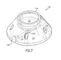
- FIG. 7is a perspective view of a second embodiment of the implantable access device of this invention having a bowl-shaped reservoir.
- FIG. 8is top plan view of the implantable access device of FIG. 7
- FIG. 9is side cross-sectional view taken along line 9 - 9 of FIG. 8 .
- FIG. 10is a perspective view of a third embodiment of the implantable access device of this invention, showing a retainer ring mounted thereto a base with a portion of a septum compressively mounted therebetween respective portions of the base and the retainer ring.
- FIG. 11is a cross sectional view of the implantable access device taken along line 11 - 11 of FIG. 10 .
- FIG. 12is a cross sectional view of the implantable access device taken along line 12 - 12 of FIG. 10 .
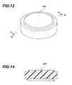
- FIG. 13is a perspective view of the septum of the implantable access device of FIG. 10 .
- FIG. 14is a cross sectional view of the septum taken along line 14 - 14 of FIG. 13 .
- FIG. 15is a perspective view of the base of the implantable access device of FIG. 10 .
- FIG. 16Ais a top elevational view of the base of FIG. 15 .
- FIG. 16Bis a cross sectional view of the base taken along line 16 - 16 of FIG. 16A .
- FIG. 17is a side elevational view of the base of FIG. 15 .
- FIG. 18is a cross sectional view of the base taken along line 18 - 18 of FIG. 17 .
- FIG. 19is an enlarged cross sectional view of a portion of the edge portion of the base of FIG. 18 .
- FIG. 20is an enlarged side elevational view of the outlet stem of the base of FIG. 15 .
- FIG. 21is a perspective view of the retainer ring of the implantable access device of FIG. 10 .
- FIG. 22is a top elevational view of the retainer ring of FIG. 21 .
- FIG. 23is a cross sectional view of the retainer ring taken along line 23 - 23 of FIG. 22 .
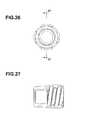
- FIG. 24is a perspective view of a lock that is configured to mount thereon at least a portion of the outlet stem of the base of the implantable access device.
- FIG. 25is a side elevational view of the lock of FIG. 24 .
- FIG. 26is an end elevational view of the lock of FIG. 24 .
- FIG. 27is a cross sectional view of the lock taken along line 27 - 27 of FIG. 26 .
- FIG. 28is a perspective view of a gasket that is configured to mount therein at least a portion of the lock of FIG. 24 .
- FIG. 29is a side elevational view of the gasket of FIG. 28 .
- FIG. 30is a perspective view of a fourth embodiment of the implantable access device of this invention, showing a retainer ring mounted thereto a base with a portion of a septum compressively mounted therebetween respective portions of the base and the retainer ring.
- FIG. 31is a cross sectional view of the implantable access device taken along line 31 - 31 of FIG. 30 .
- FIG. 32is a top elevational view of an access port having an exemplary center reservoir outlet port for a fluid dynamic study.
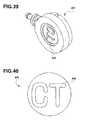
- FIG. 33is a top elevational view of an access port having an exemplary tangential, offset reservoir outlet port for a fluid dynamic study.
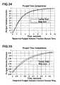
- FIG. 34shows a plot of exemplary reservoir purged volume fraction versus time.
- FIG. 35shows a plot of exemplary reservoir purged volume fraction versus time.
- FIG. 36shows exemplary fluid particle traces inside the reservoir of the access port of FIG. 32 .
- FIG. 37shows exemplary fluid particle traces inside the reservoir of the access port of FIG. 33 .
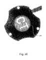
- FIG. 38illustrates a bottom surface of the fourth embodiment of an access port having exemplary identification means marked on a bottom surface thereof, shown under x-ray or CT, according to one exemplary aspect.
- FIG. 39is a perspective view of an access port having exemplary identification means marked on a bottom surface thereof.
- FIG. 40is a bottom elevational view of a disk for insertion therein an exemplary access port, having identification means marked on a bottom surface thereof the disk.
- FIG. 41is an exploded view of the access port of FIG. 39 .
- Rangesmay be expressed herein as from “about” one particular value, and/or to “about” another particular value. When such a range is expressed, another embodiment includes from the one particular value and/or to the other particular value. Similarly, when values are expressed as approximations, by use of the antecedent “about,” it will be understood that the particular value forms another embodiment. It will be further understood that the endpoints of each of the ranges are significant both in relation to the other endpoint, and independently of the other endpoint.
- FIGS. 1 and 2a known type of an implantable access port 5 is illustrated in FIGS. 1 and 2 .
- the known access portis comprised of a base 7 having a radially spaced series of suture holes 8 defined within the base. So provided, the access port may be sewn to the fascia of a patient by passing appropriate sutures through the suture holes to fasten the access port to the underlying muscle and/or tissues of the patient.
- the access port 5here features a cylindrical reservoir 9 formed within and as a part of, the base 7 .
- An outlet passageway 10extends radially away from the side wall of the reservoir 9 to an opening 11 defined within the exterior side wall of the base, the outlet passageway 10 being in fluid communication with the reservoir 9 and the exterior opening 11 .
- Absent in FIGS. 1 and 2is a penetrable septum of a type known in the art, which septum would be affixed to the open face of the base 7 by a suitable retainer ring (not illustrated).
- the outlet passageway 10extends from an opening defined in the side wall of the reservoir 9 such that both the outlet opening 11 and the outlet passageway 10 are spaced from (above) the bottom of the reservoir 9 . So defined, the outlet opening 11 forms a small ledge or catch pocket in the reservoir 9 , which may in turn lead to the occlusion of blood or other substances, respectively, in the reservoir 9 as these fluids are passed into or drawn from out of the access port.
- cylindrical reservoirs of the type shown in FIGS. 1 and 2typically enclose a large amount of space, which results in a large volume of fluid that must flow into the access port during use, and which fluid remains in the port thereafter. This extra fluid reduces the efficiency of flushing protocols by requiring larger flows of fluid over extended times to completely flush the reservoir after use. As described, this is further compounded by the positioning of the outlet step, i.e., the outlet opening and the outlet passageway 10 , at a central location within the upstanding reservoir side wall, such that a gap exists between the bottom of the reservoir 9 and the entrance to the outlet passageway 10 .
- FIGS. 3 through 6A first embodiment of the implantable access port of this invention is illustrated in FIGS. 3 through 6 .
- An implantable access port 25is illustrated having a base 27 provided with a series of radially spaced suture holes 28 , in known fashion.
- the access port 25is formed to have a bowl-shaped reservoir 29 , as best seen in FIGS. 4 and 6 .
- the bowl-shaped reservoiris defined by a single smooth-surfaced wall which defines an open top of the reservoir, and a focus or center point at the “bottom” or center of the reservoir.
- the wall of the reservoirthus comprises a continuous curvilinear side wall.
- the bowl-shaped reservoirin all of the embodiments of the present invention, may thus be parabolic in shape, as well as hemispherical or semi-hemispherical when viewed in cross-section.
- the bowl-shaped formation of the reservoir 29 in the base 27 of the access port in such a mannerthus allows for the reservoir to be made with the walls and the floor of the reservoir as one unit, i.e., one continuous wall, without otherwise forming any corners or edges associated with the reservoir at which a buildup of occluding particles could occur.
- a reservoir outlet 30is defined within the base 27 of the access port at the center or focus of the bottom of the reservoir 29 .
- the bottom of the reservoiris that portion which is opposed to the open face of the reservoir defined in the base.
- the bottom of the reservoirthus comprises the center or the focus of the reservoir, as that term is understood by those skilled in the art.
- An outlet passageway 31is also defined within the base 27 and extends in communication with the reservoir outlet 30 and an external opening 32 defined in the exterior side wall of the access port base 27 .
- the placement of the reservoir outlet 30 at the focus or center of the bowl-shaped reservoirenhances the smooth flow of material, i.e., fluids, to include medications and blood, into and out of the reservoir.
- the reservoir outlet 30is shown in FIGS. 4 and 6 to be partially recessed, i.e., partially defined or formed within the floor of the reservoir, and is positioned directly in the center of the reservoir so that the outlet, which may also be thought of as a reservoir stem, acts like a drain to remove fluid and particles from the reservoir.
- the reservoir outlet 30is defined within the base 27 of the access port so that the reservoir outlet is preferably tangential with respect to the reservoir wall, and particularly with respect to the bottom portion thereof.
- the bowl-shaped reservoir 29thus encloses the minimal amount of space required to allow a hypodermic needle (not illustrated) to access the reservoir 29 through the septum (not illustrated) of the access port.
- the septumwill comprise a penetrable septum of those types well known in the art, and will be secured to the base 27 over the open face of the reservoir by a suitable retainer ring 34 which will be threadably affixed to the base of the access port.
- the bowl-shaped reservoir of this access portwith its improved reservoir design, thus reduces the likelihood of occlusion occurrences and failures within the access port, and is believed to minimize the likelihood of the above-described patient complications.
- the volume of the bowl-shaped reservoiris greatly reduced with respect to access ports having cylindrical access ports, which thus enhances the efficiency of flushing protocols used with the port.
- the volume of the bowl-shaped reservoir 29 , 129 in FIGS. 3-9may be around 0.3 cc's, whereas the cylindrical reservoir 9 of the access port 5 ( FIGS. 1-2 ) known in the art may have a volume of approximately 0.6 to 1.0 cc's.
- FIGS. 7 through 9A second embodiment of the implantable access port of this invention is illustrated in FIGS. 7 through 9 .
- the implantable access port 125 of FIGS. 7-9includes a base 127 having a radially spaced series of suture holes 128 defined therein, as known.
- the suture holesmay be filled with a penetrable material, for example an elastomeric material, for otherwise filling the openings within the base in order to limit tissue in-growth into the suture holes or openings.
- the access port 125has a bowl-shaped reservoir 129 defined within and as a part of the base of the access port.
- the bowl-shaped reservoir 129is once again defined by a continuous smooth-surfaced wall, for example a curvilinear wall, which defines an open top of the reservoir and an opposed bottom having a focus or center point thereat, the bottom or bottom portion of the reservoir once again being that portion of the reservoir opposed to and spaced farthest from the open top or face thereof.
- the reservoirmay thus be parabolic, hemispherical, or semi-hemispherical in shape (cross-section). So fashioned, the reservoir does not provide any corners or associated edges at which a buildup of occluding particles or substances could occur.
- a reservoir outlet 130is defined within the base 127 at the bottom of the bowl-shaped reservoir, and more particularly at the center thereof, and is in communication with an elongate outlet passageway 131 defined within the base 127 and extending in communication with the reservoir outlet 130 to an external opening 132 defined within the exterior side wall of the base.
- the outlet openingmay best be thought of as an outlet stem extending from the center or focus of the bowl-shaped reservoir.
- the reservoir outlet 130is fully recessed in the base with respect to the bottom, center of the reservoir, as best shown in FIGS. 8 and 9 , for forming a more discrete reservoir drain.
- the access port 125is provided with a penetrable septum 133 of known construction, the septum being secured on the base 127 of the access port by a retainer ring 134 threadably affixed to the base.
- the manner of fabrication, and materials used in the construction of the implantable access ports 25 and 125 of this invention, respectively,are as described in U.S. Pat. Nos. 4,673,394, and 5,951,512, each of which is fully incorporated herein by this reference.
- the bowl-shaped reservoir 129allows for an entirely smooth geometry in the reservoir in that the reservoir wall does not have any corners or edges that may catch materials or substances which might otherwise settle on or occlude at least a portion of the reservoir or reservoir outlet.
- the placement of the respective outlets 30 , 130 , at the bottom or center of the reservoir, preferably tangentially with respect thereto as illustrated in FIG. 9 , and either partially or fully recessed in the base with respect to the reservoir bottom,further prevents the formation of any “dead space” which would otherwise allow the buildup of particles which may lead to occlusion of the access port.
- the bowl-shaped reservoir of this access porttherefore, with its improved reservoir design, reduces the likelihood of these types of occlusion occurrences and failures, and is believed to minimize the likelihood of the above-described patient complications.
- the implantable access port 225 for use in transferring a fluid transdermally between an external fluid storage or dispensing device and a site within a patient's bodycan comprise a base 227 (such as shown, for example, in FIGS. 15-19 ), a means for increasing the purging performance of the port, and a septum secured to the base and enclosing a reservoir within the base.
- the means for increasing the purging performance of the portcan comprise a bowl-shaped reservoir 229 defined within the base by a smooth surfaced wall, a reservoir outlet 230 , and an outlet passageway 231 positioned in operative communication with the reservoir outlet.
- the reservoir 229has a top edge, a bottom portion and a side portion that extends between the bottom portion and the top edge.
- the reservoir outlet 230can be defined on the side portion of the reservoir.
- the reservoir outlet 230 and the outlet passageway 231can be positioned in a plane that overlies and is spaced from a center of the bottom portion of the reservoir and the top edge of the reservoir. In one aspect, the plane can be substantially parallel to the top edge of the reservoir.
- the reservoirhas a reservoir axis that extends through the center of the bottom portion.
- the outlet passageway 231has a passageway axis that substantially bisects the reservoir axis.
- the passageway 231 axisbisects the reservoir axis at substantially a right angle (such as shown, for example, in FIG. 32 ).
- the outlet passageway 231can be positioned such that it extends substantially offset from the center of the reservoir.
- the passageway axisdoes not bisect the reservoir axis.
- the axis of the outlet passagewaycan extend substantially tangent to a portion of the wall of the reservoir that is spaced from the center of the reservoir (such as shown, for example, in FIG. 33 ).
- the outlet passageway 231is defined within the base 227 and is in fluid communication with an external opening that is defined in the exterior of the base.
- the external base openingis configured to be placed in sealed fluid communication with a catheter.
- the reservoircan be defined by a single continuous wall.
- the wallcan be a curvilinear wall.
- at least a portion of the reservoir 229can be formed as a parabola, or can be hemispherical or semi-hemispherical in shape.
- the shaped portion of the wall of the reservoircan have any desired geometric curved shape.
- the access portcan comprise a retainer ring 234 , such as shown in FIGS. 21-23 that is configured for connecting to an exterior portion of the base 227 .
- the retainer ring 234defines an opening that is circumferentially surrounded by a lip portion. Referring to FIG. 10 , when the retainer ring 234 is coupled to the base 227 , an upper shoulder surface of the base, which substantially surrounds the top edge of the reservoir of the base, and the lip portion of the retainer ring define a circumferentially extending slot that has a height dimension.
- the septum 233( FIGS. 13 and 14 ) of the access port has an edge portion.
- the septumwhen the septum is not mounted in the access port, it is substantially planar in shape and has a substantially planar and substantially uniform height. In one aspect, the height of the septum is greater than the height of the lip portion.
- the edge portion of the septumin order to operationally fluidically seal the septum 233 therein the circumferentially extending slot and thereby between portions of the upper shoulder surface of the base and the lip portion of the retainer ring 234 , the edge portion of the septum is configured to be received therein the formed circumferentially extending slot such that the edge portion of the septum is compressively seated therebetween the base and the retainer ring.
- the implantable access port 325 for use in transferring a fluid transdermally between an external fluid storage or dispensing device and a site within a patient's bodycan comprise base 327 .
- the base 327has a circumferential shape in which at least three notches are defined therein the outer surface of the base 327 .
- the notchesmay be spaced equidistantly from one another.
- the base 327may have up to twelve notches.
- the portalso comprises a means for increasing the purging performance of the port, and a septum 333 of known construction secured to the base 327 and enclosing a reservoir 329 within the base 327 .
- the penetrable septum 333is secured on the base 327 of the access port by a retainer ring 334 threadably affixed to the base 327 .
- the means for increasing the purging performance of the portcan comprise a reservoir defined within the base 327 by a smooth surfaced wall, a reservoir outlet 330 , and an outlet passageway positioned in operative communication with the reservoir outlet 330 .
- the outlet passagewayhas a passageway axis that substantially bisects the reservoir axis.
- the outlet passagewaycan be positioned such that it extends substantially offset from the center of the reservoir, as also described above and illustrated in FIG. 33 .
- the outlet passagewayis defined within the housing 327 and is in fluid communication with an external opening that is defined in the exterior of the housing 327 .
- the external base openingis configured to be placed in sealed fluid communication with a catheter.
- the design of the reservoir of the exemplary access portsenhances the flushing capability of the respective ports.
- a computational fluid dynamics analysis of reservoir cavities, such as embodied in FIGS. 36 and 37was conducted and their respective flushing characteristics were studied.
- the representative access portswere injected with 10 cc of saline.
- the studiesinvestigated the effects of moving the reservoir outlet from a position in the curvilinear wall of the reservoir that bisected the reservoir axis to a position in the curvilinear wall such that the axis of the reservoir outlet was in a tangential, offset position.
- the simulationswere conducted using CFdesign version 9.0 from Blue Ridge Numerics, Inc. Exemplary sectional views of the reservoir designs that were studied are shown in FIGS. 32 and 33 .
- FIGS. 34 and 35The results of the studies are illustrated in FIGS. 34 and 35 .
- FIG. 34a plot comparing the purged volume fraction versus time for both the center and side exit reservoir outlet chamber design is illustrated.
- the studydemonstrated that the tangentially positioned outlet port enabled the reservoir to purge slightly quicker than the “central” outlet port design.
- FIG. 35shows purge data similar to FIG. 34 , but over a specific range to better illustrate the differences between the designs of the reservoirs of the respective access ports.
- FIGS. 36 and 37show exemplary particle traces released into the incoming fluid stream of each reservoir design.
- a large amount of flow recirculationexists inside the chambers.
- the significant amount of low velocity, “tumbling” flow on the sides of the respective reservoir chambersis noteworthy.
- the increased level of flow circulation in the curvilinear wall reservoir designsmay be directly related to an increase in purging performance.
- Particle tracesappear to fill the reservoir chamber substantially, which helps to evacuate fluid located in the upper corners of the reservoir.
- fluid velocity magnitude inside the needle, reservoir chamber, and outlet portare nearly identical.
- the fluid pressure drop from the needle inlet to the outlet port exit for each designwas found to be nearly identical at about 5 psi. This would indicate that both designs require substantially about the same amount of needle pressure force to achieve the desired purging flow rate.
- the exemplary center exit and side exit reservoir cavitiesresult in very similar flow and pressure fields.
- the side exit designis able to purge its reservoir chamber slightly quicker and without any additional fluid pressure drop. The slight increase in purging performance is likely due to increased levels of fluid recirculation inside the chamber, caused by the tangential location of the outlet port. Increased levels of recirculation appear to aide in overall reservoir purging performance.
- FIG. 1For example, and not meant to be limiting, at least one or perhaps multiple identifiable feature(s) of an access port contemplated by the instant disclosure may be correlative to information (e.g., a manufacturer's model or design) pertaining to the access port.
- informatione.g., a manufacturer's model or design
- an identifiable feature from a particular model of an access portmay be unique in relation to at least one of the identifiable features of another model access port.
- the at least one identifiable feature of an access portmay be further correlative with any information of interest, such as type of port, catheter type, manufacturer, date of manufacture, material lots, part numbers, etc.
- correlation of such at least one feature of an access portmay be accomplished, and information pertaining to the access port may be obtained.
- the access port of the present inventioncan comprise at least one feature of the access port that is structured to operatively identify the access port subsequent to subcutaneous implantation.
- the at least one identifiable featuremay be perceived by palpation (i.e., to examine by touch), by way of other physical interaction, or by visual observation.
- the at least one feature of the access portcan comprise at least one of: a protrusion, a protruding region, a circumferentially extending protrusion, a recess, a recessed region, a circumferentially extending recess, at least one suture aperture, an overhanging rim feature, a lip feature, an undulation, and/or adjacent features of different elevation.
- a person of interestmay touch or feel the access port through the skin to perceive at least one identifying feature of the implanted access port.
- the retainer ring of the access portcan include a plurality of protrusions that can be spaced about the periphery of the septum as desired.
- the plurality of protrusionscan be symmetrically circumferentially spaced about the periphery of the septum.
- the protrusion(s)may be sized, configured, and positioned for forming the at least one identifiable feature of an access port.
- the identifiable feature of the access portmay be structured for facilitating comfort of a patient within which the access port is implanted.
- the overall geometry of the access portcan be shaped such that the overall general shape of the access port can act as the at least one identifiable feature. It is contemplated that any geometric shape and/or geometric design could be implemented in the general exterior surface shape of the access port such that the shape and/or design could function as an identifiable feature.
- the at least one identifiable featuremay be perceived via x-ray or ultrasound imaging.
- the at least one identifiable featurecan comprise a marking on the access port that is formed of material that is visible under application of x-ray or ultrasound technology.
- the at least one identifiable featurecan comprise a marking therein the access port that is formed of material that is visible under application of x-ray or ultrasound technology.
- the “identifiable feature”may not be observable visually or by palpation but, rather, may be otherwise observable via conventional imaging technology such as x-ray or ultrasound.
- a metalized featuree.g., a plate or other metal geometry
- such a metal featuremay be represented on an x-ray generated by exposure of the access port to x-ray energy while simultaneously exposing x-ray sensitive film to x-ray energy passing through the access port.
- a size, shape, or both size and shape of a metal or metalized feature of an access portmay be configured for enhancing identification of an access port, i.e., for identifying an implanted access port as a CT port that is suitable for power injection.
- a portion of the access portis marked with a “CT” lettering that is visible under radiological conditions, such as shown in FIG. 38 .
- the portcan be made of titanium, in which the letters “CT” can be etched into the bottom side of the port and can act as identifying means 243 .
- any means for identifying the portcan be etched into the bottom side of the port, including one or more alpha-numeric characters, one or more symbols, or other identifying means.
- the absence of titanium material in portions of the bottom surface of the portcreates an enhanced contrast under radiological conditions, under which the letters can be more visible.
- the letterscan be etched into the bottom of the port using a machine engraving process.
- the letterscan be etched at a depth of from about 0.010 inches to about 0.020 inches from the bottom surface of the port.
- the letterscan be etched into the bottom of the port at a depth of approximately 0.015 inches, which, in a particular aspect, can be equal to approximately half of the thickness of the wall of the port, or approximately 0.030 inches.
- the letterscan be formed from platinum wire, such as 0.010′′ thick platinum wire, which can be adhered to the bottom side of the access port with an adhesive, such as a silicone adhesive.
- the letterscan be made from a tungsten filled room temperature vulcanizing (RTV) silicone rubber that are cast and then adhered to the back of the port with an adhesive, such as a silicone adhesive.
- RTVroom temperature vulcanizing
- the bottom side of the portcould be engraved to form the “CT” lettering and then the engraving could be filled with a tungsten filled RTV silicone.
- the RTV silicone rubberhas long been used in the medical device industry both as an adhesive and as a base compound.
- identifying means 343can be carved out of the bottom surface of the port.
- the letters “CT”may be raised letters in relation to the bottom surface of the port.
- the “CT” lettersmay be etched out of the bottom of the surface using a process similar to the machine engraving process, as described above.
- the bottom surface of the portcan have no “CT” letters carved from the bottom surface.
- the “CT” lettersare positioned therein the center of a first circular recessed portion defined therein the bottom surface of the port. A second recessed portion circumferentially surrounds the first recessed portion.
- the first recessed portionis defined therein the bottom of the port surface at a greater recess depth, compared to the second recessed portion that circumferentially surrounds the first recessed portion.
- the first recessed portionis approximately 0.031 inches from the bottom surface of the port, while the second recessed portion may be approximately 0.021 inches from the bottom surface of the port.
- the diameter of the first recessed portionis approximately 0.450 inches.
- the diameter of the second recessed portionis approximately 0.513 inches.
- the overall diameter of the bottom of the portmay be approximately 0.825 inches.
- a disk 345is etched through using a machine engraving process, such that an absence of a portion of the disk material is created, thereby forming the letters “CT”.
- the disk 345is then inserted therein the first recessed portion of the port and adhered thereto, such that the cut-out letters in the disk 345 .
- the outer surface of the disk 345may lie flush with the raised “CT” letters from the first recessed portion, if the “CT” letters are raised in relation to the bottom surface of the port.
- the disk 345may be composed of titanium.
- the disk 345may be composed of any suitable biocompatible material.
- any means for identifying the portcan be etched into or carved from the bottom side of the port, including one or more alpha-numeric characters, one or more symbols, or other identifying means, as described above.
- the outer diameter of the disk 345is approximately 0.440 inches.
- the width of the “CT” lettersmay be approximately 0.346 inches, and the height of the “CT” letters may be approximately 0.237 inches.
- the thickness of the disk 345is approximately 0.010 inches.
- a plastic cap 367is then inserted on top of the disk 345 , such that the outer surface of the plastic cap becomes flush with the bottom surface of the port.
- the plastic cap 367has a first portion which is configured to fit into the first recessed portion of the bottom surface of the port, and a second portion which is configured to fit into the second recessed portion of the bottom surface of the port.
- the portmay be composed of any suitable biocompatible plastic material.
- the plastic cap 367may have an outer diameter of approximately 0.510 inches and an inner diameter of approximately 0.489 inches. In one aspect, the plastic cap 367 may have a depth of approximately 0.035 inches.
- tungstenwas representatively selected as it is readily available and has been used in many medical applications. Further, if the port is made of titanium, selecting tungsten allows the lettering to be more visible under radiology conditions as tungsten is denser than the titanium. However, one would appreciate that it is contemplated that other biocompatible dense metals could comprise at least a portion of a metalized letter.
- the tungsten that is mixed in the silicone rubber RTVcan be about 25-micron particle size.
- RTVis a relatively soft paste with the consistency similar to yogurt.
- the tungstencan be mixed at relative high concentrations by weight between about 100 to 500 percent by weight, and preferably between about 150 to 400 percent by weight.
- the identifiable feature of the access portcan be configured for detection via ultrasound interaction.
- such an identifiable featuremay comprise an exterior topographical feature.
- such an identifiable featurecan comprise a composite structure including two or more materials that form an interface surface that may be identified by ultrasound imaging.
- the at least one identifiable featuremay be perceived through magnetic, light, or radio energy interaction or communication with the access port.
- the at least one identifiable featurecomprises a passive RFID tag that is configured to operate without a separate external power source and to obtain operating power from a reader located external to the subject.
- Exemplary passive RFID tagsare typically programmed with a unique set of data (usually 32 to 128 bits) that cannot be modified. Read-only tags can operate as an identifier comparable to linear barcodes that may contain selected product-specific information.
- the at least one identifiable feature of an access portmay be correlative with the access port being power injectable.
- the at least one identifiable feature of the access portcan be configured to identify the access port as being power injectable subsequent to subcutaneous implantation.
- the penetrable septums of the preferred embodiments of this inventionare comprised of a self-resealing polymer, which is preferably an elastomer, such as silicon rubber or a latex, and which is adapted to permit access using a hypodermic needle (not illustrated) into the reservoir formed within the respective access ports.
- the respective bases and retainer ringsare each preferably comprised of a biocompatible material, such as electropolished stainless steel, or other surgical grades of steel, to also include a biocompatible hard material such as titanium.
- the access portwith the exception of the septum, can be manufactured of a suitable plastic material intended for implantation within a human body, and approved for use therefore.
- the base of the access portin association with the external opening defined in the side wall of the base, for all embodiments of the inventive access port, are provided with a catheter mount of known construction, which for example, may comprise the locking type of catheter mount illustrated in the '394 patent to Fenton et al., the teaching of which has been incorporated herein by reference.
- the access port of the present inventioncan further comprise a lock assembly 237 that is configured to mount thereon at least a portion of an outlet stem 235 that extends outwardly from a peripheral edge of the base of the access port.
- This lock assemblyengages the catheter as a lock of the lock assembly is twisted into an engaged position, which results in a fluidically sealed connection of a catheter to the outlet stem and effects fluid communication from the catheter to the outlet passageway that is defined therein the outlet stem.
- the exterior surface of at least a portion of the outlet stemis configured for receiving a conventional catheter and a lock assembly.
- the distal end portion of the outlet stemis configured for operative receipt of an end of the catheter.
- a portion of the distal end portion of the outlet stemcan form a male ridge that can aid in preventing undesired separation of the catheter from the outlet stem.
- the adjoining proximal end portion of the outlet stem 235which substantially abuts the exterior surface of peripheral edge of the base, can have an exterior surface that is configured to cooperatively engage an internal mount surface of a lock of the lock assembly.
- the internal mount surface of the lockis formed in an open first end portion of a bore defined therein the lock.
- a male ridgeis formed that extends inwardly into the center of the lock.
- the lock assemblycan further comprise a gasket 239 (such as shown in FIGS. 28-29 ) that is configured to be operatively received therein a portion of the bore.
- a portion of the exterior surface of the gasketcan form a peripherally extending groove that is configured to cooperatively mount therewith the male ridge that is formed in the second end portion of the lock.
Landscapes
- Health & Medical Sciences (AREA)
- Heart & Thoracic Surgery (AREA)
- Pulmonology (AREA)
- Engineering & Computer Science (AREA)
- Anesthesiology (AREA)
- Biomedical Technology (AREA)
- Hematology (AREA)
- Life Sciences & Earth Sciences (AREA)
- Animal Behavior & Ethology (AREA)
- General Health & Medical Sciences (AREA)
- Public Health (AREA)
- Veterinary Medicine (AREA)
- Media Introduction/Drainage Providing Device (AREA)
Abstract
Description
Claims (3)
Priority Applications (4)
| Application Number | Priority Date | Filing Date | Title |
|---|---|---|---|
| US12/206,226US8926573B2 (en) | 2002-04-02 | 2008-09-08 | Implantable access port |
| US29/328,079USD650475S1 (en) | 2007-09-07 | 2008-11-18 | Implantable port |
| US14/558,213US20160317797A1 (en) | 2002-04-02 | 2014-12-02 | Implantable Access Port |
| US16/112,747US20190054284A1 (en) | 2005-12-23 | 2018-08-26 | Implantable Access Port |
Applications Claiming Priority (5)
| Application Number | Priority Date | Filing Date | Title |
|---|---|---|---|
| US10/114,343US6997914B2 (en) | 2001-04-02 | 2002-04-02 | Implantable access port |
| US11/317,284US20060184141A1 (en) | 2001-04-02 | 2005-12-23 | Implantable access port |
| US97081607P | 2007-09-07 | 2007-09-07 | |
| US4473408P | 2008-04-14 | 2008-04-14 | |
| US12/206,226US8926573B2 (en) | 2002-04-02 | 2008-09-08 | Implantable access port |
Related Parent Applications (2)
| Application Number | Title | Priority Date | Filing Date |
|---|---|---|---|
| US11/317,284Continuation-In-PartUS20060184141A1 (en) | 2001-04-02 | 2005-12-23 | Implantable access port |
| US29/284,976ContinuationUSD595892S1 (en) | 2007-09-07 | 2007-09-19 | Scalloped implantable injectable port |
Related Child Applications (3)
| Application Number | Title | Priority Date | Filing Date |
|---|---|---|---|
| US10/114,343ContinuationUS6997914B2 (en) | 2001-04-02 | 2002-04-02 | Implantable access port |
| US29/328,079ContinuationUSD650475S1 (en) | 2007-09-07 | 2008-11-18 | Implantable port |
| US14/558,213ContinuationUS20160317797A1 (en) | 2002-04-02 | 2014-12-02 | Implantable Access Port |
Publications (2)
| Publication Number | Publication Date |
|---|---|
| US20090227862A1 US20090227862A1 (en) | 2009-09-10 |
| US8926573B2true US8926573B2 (en) | 2015-01-06 |
Family
ID=40452323
Family Applications (2)
| Application Number | Title | Priority Date | Filing Date |
|---|---|---|---|
| US12/206,226Expired - Fee RelatedUS8926573B2 (en) | 2002-04-02 | 2008-09-08 | Implantable access port |
| US29/328,079ActiveUSD650475S1 (en) | 2007-09-07 | 2008-11-18 | Implantable port |
Family Applications After (1)
| Application Number | Title | Priority Date | Filing Date |
|---|---|---|---|
| US29/328,079ActiveUSD650475S1 (en) | 2007-09-07 | 2008-11-18 | Implantable port |
Country Status (4)
| Country | Link |
|---|---|
| US (2) | US8926573B2 (en) |
| EP (1) | EP2190517A4 (en) |
| AU (1) | AU2008299945A1 (en) |
| WO (1) | WO2009035582A1 (en) |
Cited By (6)
| Publication number | Priority date | Publication date | Assignee | Title |
|---|---|---|---|---|
| US10406274B1 (en) | 2017-06-02 | 2019-09-10 | Jose Ramirez | Accessing assembly for hemodialysis administration |
| US11096582B2 (en) | 2018-11-20 | 2021-08-24 | Veris Health Inc. | Vascular access devices, systems, and methods for monitoring patient health |
| US11766550B2 (en) | 2017-05-21 | 2023-09-26 | Veris Health, Inc. | Implantable medication infusion port with physiologic monitoring |
| US12123654B2 (en) | 2010-05-04 | 2024-10-22 | Fractal Heatsink Technologies LLC | System and method for maintaining efficiency of a fractal heat sink |
| US12239811B2 (en) | 2018-11-20 | 2025-03-04 | Veris Health Inc. | Wireless charging, localization, and data communication for implantable vascular access devices |
| US12251201B2 (en) | 2019-08-16 | 2025-03-18 | Poltorak Technologies Llc | Device and method for medical diagnostics |
Families Citing this family (64)
| Publication number | Priority date | Publication date | Assignee | Title |
|---|---|---|---|---|
| US8177762B2 (en) | 1998-12-07 | 2012-05-15 | C. R. Bard, Inc. | Septum including at least one identifiable feature, access ports including same, and related methods |
| US8926573B2 (en) | 2002-04-02 | 2015-01-06 | Angiodynamics, Inc. | Implantable access port |
| US7947022B2 (en)* | 2005-03-04 | 2011-05-24 | C. R. Bard, Inc. | Access port identification systems and methods |
| US8029482B2 (en) | 2005-03-04 | 2011-10-04 | C. R. Bard, Inc. | Systems and methods for radiographically identifying an access port |
| JP5484674B2 (en) | 2005-03-04 | 2014-05-07 | シー・アール・バード・インコーポレーテッド | Access port and identification method |
| US9474888B2 (en) | 2005-03-04 | 2016-10-25 | C. R. Bard, Inc. | Implantable access port including a sandwiched radiopaque insert |
| EP3884989B1 (en) | 2005-04-27 | 2022-07-13 | C. R. Bard, Inc. | Vascular access port |
| EP1874393B1 (en) | 2005-04-27 | 2017-09-06 | C.R.Bard, Inc. | Infusion apparatuses |
| US10307581B2 (en) | 2005-04-27 | 2019-06-04 | C. R. Bard, Inc. | Reinforced septum for an implantable medical device |
| US9265912B2 (en) | 2006-11-08 | 2016-02-23 | C. R. Bard, Inc. | Indicia informative of characteristics of insertable medical devices |
| US9642986B2 (en) | 2006-11-08 | 2017-05-09 | C. R. Bard, Inc. | Resource information key for an insertable medical device |
| US8814868B2 (en) | 2007-02-28 | 2014-08-26 | Smith & Nephew, Inc. | Instrumented orthopaedic implant for identifying a landmark |
| US8784425B2 (en) | 2007-02-28 | 2014-07-22 | Smith & Nephew, Inc. | Systems and methods for identifying landmarks on orthopedic implants |
| EP2114263B1 (en)* | 2007-02-28 | 2019-02-20 | Smith & Nephew, Inc. | System for identifying a landmark |
| ES2651269T3 (en) | 2007-06-20 | 2018-01-25 | Medical Components, Inc. | Venous reservoir with molded indications and / or radiopacas |
| US9610432B2 (en) | 2007-07-19 | 2017-04-04 | Innovative Medical Devices, Llc | Venous access port assembly with X-ray discernable indicia |
| WO2009012385A1 (en) | 2007-07-19 | 2009-01-22 | Medical Components, Inc. | Venous access port assembly with x-ray discernable indicia |
| US9579496B2 (en) | 2007-11-07 | 2017-02-28 | C. R. Bard, Inc. | Radiopaque and septum-based indicators for a multi-lumen implantable port |
| US9220514B2 (en) | 2008-02-28 | 2015-12-29 | Smith & Nephew, Inc. | System and method for identifying a landmark |
| US9023063B2 (en) | 2008-04-17 | 2015-05-05 | Apollo Endosurgery, Inc. | Implantable access port device having a safety cap |
| BRPI0910460A2 (en) | 2008-04-17 | 2018-02-14 | Allergan Inc | implantable access door device and fastening system |
| ES2906416T3 (en) | 2008-10-31 | 2022-04-18 | Bard Inc C R | Systems and methods to identify an access road |
| US8932271B2 (en)* | 2008-11-13 | 2015-01-13 | C. R. Bard, Inc. | Implantable medical devices including septum-based indicators |
| US11890443B2 (en) | 2008-11-13 | 2024-02-06 | C. R. Bard, Inc. | Implantable medical devices including septum-based indicators |
| US9031637B2 (en) | 2009-04-27 | 2015-05-12 | Smith & Nephew, Inc. | Targeting an orthopaedic implant landmark |
| US8945147B2 (en) | 2009-04-27 | 2015-02-03 | Smith & Nephew, Inc. | System and method for identifying a landmark |
| EP2451512A1 (en) | 2009-07-07 | 2012-05-16 | C.R. Bard Inc. | Extensible internal bolster for a medical device |
| US8715158B2 (en) | 2009-08-26 | 2014-05-06 | Apollo Endosurgery, Inc. | Implantable bottom exit port |
| US8708979B2 (en) | 2009-08-26 | 2014-04-29 | Apollo Endosurgery, Inc. | Implantable coupling device |
| US8086734B2 (en) | 2009-08-26 | 2011-12-27 | International Business Machines Corporation | Method of autonomic representative selection in local area networks |
| US8506532B2 (en) | 2009-08-26 | 2013-08-13 | Allergan, Inc. | System including access port and applicator tool |
| USD674093S1 (en)* | 2009-08-26 | 2013-01-08 | Smith & Nephew, Inc. | Landmark identifier for targeting a landmark of an orthopaedic implant |
| US8092435B2 (en) | 2009-10-16 | 2012-01-10 | Smiths Medical Asd, Inc. | Portal with septum embedded indicia |
| ES2695907T3 (en) | 2009-11-17 | 2019-01-11 | Bard Inc C R | Overmolded access port that includes anchoring and identification features |
| US8657795B2 (en)* | 2009-12-30 | 2014-02-25 | Cook Medical Technologies Llc | Vascular port |
| US8882728B2 (en) | 2010-02-10 | 2014-11-11 | Apollo Endosurgery, Inc. | Implantable injection port |
| US8738151B2 (en)* | 2010-04-28 | 2014-05-27 | Medtronic, Inc. | Body portal anchors and systems |
| US8992415B2 (en) | 2010-04-30 | 2015-03-31 | Apollo Endosurgery, Inc. | Implantable device to protect tubing from puncture |
| US20110270021A1 (en) | 2010-04-30 | 2011-11-03 | Allergan, Inc. | Electronically enhanced access port for a fluid filled implant |
| US20110270025A1 (en) | 2010-04-30 | 2011-11-03 | Allergan, Inc. | Remotely powered remotely adjustable gastric band system |
| RU2012157125A (en) | 2010-06-03 | 2014-07-20 | Смит Энд Нефью, Инк. | ORTHOPEDIC IMPLANT |
| US20120041258A1 (en) | 2010-08-16 | 2012-02-16 | Allergan, Inc. | Implantable access port system |
| US20120065460A1 (en) | 2010-09-14 | 2012-03-15 | Greg Nitka | Implantable access port system |
| USD676955S1 (en) | 2010-12-30 | 2013-02-26 | C. R. Bard, Inc. | Implantable access port |
| USD682416S1 (en) | 2010-12-30 | 2013-05-14 | C. R. Bard, Inc. | Implantable access port |
| WO2012103169A2 (en) | 2011-01-25 | 2012-08-02 | Smith & Nephew, Inc. | Targeting operation sites |
| RU2013153116A (en) | 2011-05-06 | 2015-06-20 | Смит Энд Нефью, Инк. | TARGETING FOR SIGNIFICANT POINTS OF ORTHOPEDIC DEVICES |
| US8821373B2 (en) | 2011-05-10 | 2014-09-02 | Apollo Endosurgery, Inc. | Directionless (orientation independent) needle injection port |
| WO2012173890A2 (en) | 2011-06-16 | 2012-12-20 | Smith & Nephew, Inc. | Surgical alignment using references |
| US8801597B2 (en) | 2011-08-25 | 2014-08-12 | Apollo Endosurgery, Inc. | Implantable access port with mesh attachment rivets |
| US9199069B2 (en) | 2011-10-20 | 2015-12-01 | Apollo Endosurgery, Inc. | Implantable injection port |
| US8858421B2 (en) | 2011-11-15 | 2014-10-14 | Apollo Endosurgery, Inc. | Interior needle stick guard stems for tubes |
| US9089395B2 (en) | 2011-11-16 | 2015-07-28 | Appolo Endosurgery, Inc. | Pre-loaded septum for use with an access port |
| US20150343192A1 (en)* | 2011-12-21 | 2015-12-03 | Terumo Clinical Supply Co., Ltd. | Liquid medicine injection device of subcutaneous implant type |
| BR112014022820B1 (en)* | 2012-03-16 | 2022-01-04 | Pfm Medical, Inc | METHOD FOR MARKING AN IMPLANTABLE INJECTION PORT AND INJECTION PORT WITH DISCERNIBLE MARKERS FOR IDENTIFICATION |
| JP6470177B2 (en)* | 2012-08-21 | 2019-02-13 | シー・アール・バード・インコーポレーテッドC R Bard Incorporated | Implantable access port with sandwiched radiopaque insert |
| US10463845B2 (en) | 2013-01-23 | 2019-11-05 | C.R. Bard, Inc. | Low-profile access port |
| US11420033B2 (en) | 2013-01-23 | 2022-08-23 | C. R. Bard, Inc. | Low-profile single and dual vascular access device |
| US11464960B2 (en) | 2013-01-23 | 2022-10-11 | C. R. Bard, Inc. | Low-profile single and dual vascular access device |
| TW201440745A (en) | 2013-03-14 | 2014-11-01 | Smiths Medical Asd Inc | Portal and septum therefor |
| USD870264S1 (en) | 2017-09-06 | 2019-12-17 | C. R. Bard, Inc. | Implantable apheresis port |
| USD908204S1 (en) | 2017-10-16 | 2021-01-19 | Angiodynamics, Inc. | Implantable port |
| WO2021011902A1 (en) | 2019-07-17 | 2021-01-21 | NXgenPort, L.L.C. | Implantable venous access port with remote physiological monitoring capabilities |
| USD1085416S1 (en)* | 2023-10-27 | 2025-07-22 | Guangzhou Ekai Electronic Technology Co., Ltd. | Skincare microneedling device for beauty machine |
Citations (53)
| Publication number | Priority date | Publication date | Assignee | Title |
|---|---|---|---|---|
| US4405305A (en) | 1980-10-27 | 1983-09-20 | University Of Utah Research Foundation | Subcutaneous peritoneal injection catheter |
| US4425119A (en) | 1982-01-25 | 1984-01-10 | Berglund Rickey T | Implantable device for intravascular access |
| US4571749A (en) | 1982-09-21 | 1986-02-25 | The Johns Hopkins University | Manually actuated hydraulic sphincter |
| US4587954A (en) | 1983-12-29 | 1986-05-13 | Habley Medical Technology Corporation | Elastomeric prosthetic sphincter |
| US4645495A (en) | 1985-06-26 | 1987-02-24 | Vaillancourt Vincent L | Vascular access implant needle patch |
| US4673394A (en) | 1986-01-17 | 1987-06-16 | Strato Medical Corporation | Implantable treatment reservoir |
| US4710174A (en) | 1985-12-16 | 1987-12-01 | Surgical Engineering Associates, Inc. | Implantable infusion port |
| US4767410A (en) | 1985-12-16 | 1988-08-30 | Surgical Engineering Associates, Inc. | Implantable infusion port |
| US4778452A (en) | 1985-12-16 | 1988-10-18 | Surgical Engineering Associates, Inc. | Implantable infusion port |
| US4781695A (en) | 1986-07-11 | 1988-11-01 | Dalton Michael J | Implantable fluid dispenser |
| US4822341A (en) | 1987-11-20 | 1989-04-18 | Impra, Inc. | Vascular access fistula |
| US4886501A (en) | 1987-08-25 | 1989-12-12 | Shiley Infusaid Inc. | Implantable device |
| US4955861A (en) | 1988-04-21 | 1990-09-11 | Therex Corp. | Dual access infusion and monitoring system |
| US4983162A (en) | 1987-11-23 | 1991-01-08 | Lg Medical | Implantable device for access to the blood circulatory system |
| US5041098A (en) | 1989-05-19 | 1991-08-20 | Strato Medical Corporation | Vascular access system for extracorporeal treatment of blood |
| US5092849A (en) | 1987-08-25 | 1992-03-03 | Shiley Infusaid, Inc. | Implantable device |
| US5167638A (en)* | 1989-10-27 | 1992-12-01 | C. R. Bard, Inc. | Subcutaneous multiple-access port |
| US5178612A (en) | 1990-10-10 | 1993-01-12 | Strato Medical Corporation | Compressible split cylinder bayonet locking device for attachment of a catheter to a fluid transfer device |
| US5203771A (en) | 1989-06-26 | 1993-04-20 | University Of Florida | Arterial/venous fluid transfer system |
| US5213574A (en) | 1991-09-06 | 1993-05-25 | Device Labs, Inc. | Composite implantable biocompatible vascular access port device |
| USD337637S (en) | 1991-02-20 | 1993-07-20 | Device Labs, Inc. | Implantable drug delivery port |
| US5263930A (en) | 1990-03-01 | 1993-11-23 | William D. Ensminger | Implantable access devices |
| US5281205A (en) | 1992-03-11 | 1994-01-25 | Mcpherson William E | Vascular access system and clearing method |
| US5318545A (en) | 1991-09-06 | 1994-06-07 | Device Labs, Inc. | Composite implantable biocompatible vascular access port device |
| US5387192A (en) | 1994-01-24 | 1995-02-07 | Sims Deltec, Inc. | Hybrid portal and method |
| US5399168A (en) | 1991-08-29 | 1995-03-21 | C. R. Bard, Inc. | Implantable plural fluid cavity port |
| US5520632A (en) | 1991-04-11 | 1996-05-28 | Robert Leveen | Ascites valve |
| US5527307A (en) | 1994-04-01 | 1996-06-18 | Minimed Inc. | Implantable medication infusion pump with discharge side port |
| US5695490A (en) | 1995-06-07 | 1997-12-09 | Strato/Infusaid, Inc. | Implantable treatment material device |
| US5702363A (en) | 1995-06-07 | 1997-12-30 | Flaherty; J. Christopher | Septumless implantable treatment material device |
| US5713844A (en) | 1997-01-10 | 1998-02-03 | Peyman; Gholam A. | Device and method for regulating intraocular pressure |
| US5741228A (en) | 1995-02-17 | 1998-04-21 | Strato/Infusaid | Implantable access device |
| US5792104A (en) | 1996-12-10 | 1998-08-11 | Medtronic, Inc. | Dual-reservoir vascular access port |
| US5810789A (en) | 1996-04-05 | 1998-09-22 | C. R. Bard, Inc. | Catheters with novel lumen shapes |
| US5830172A (en) | 1991-04-11 | 1998-11-03 | Leveen; Harry H. | Ascites valve |
| US5836935A (en) | 1994-11-10 | 1998-11-17 | Ashton; Paul | Implantable refillable controlled release device to deliver drugs directly to an internal portion of the body |
| US5951512A (en)* | 1996-05-28 | 1999-09-14 | Horizon Medical Products, Inc. | Infusion port with modified drug reservoir |
| US5957890A (en) | 1997-06-09 | 1999-09-28 | Minimed Inc. | Constant flow medication infusion pump |
| US5989216A (en)* | 1995-06-29 | 1999-11-23 | Sims Deltec, Inc. | Access portal and method |
| US6086555A (en) | 1997-01-17 | 2000-07-11 | C. R. Bard, Inc. | Dual reservoir vascular access port with two-piece housing and compound septum |
| US6102884A (en) | 1997-02-07 | 2000-08-15 | Squitieri; Rafael | Squitieri hemodialysis and vascular access systems |
| US6120492A (en) | 1997-07-18 | 2000-09-19 | Vasca, Inc. | Method and apparatus for percutaneously accessing an implanted port |
| US6213973B1 (en) | 1998-01-12 | 2001-04-10 | C. R. Bard, Inc. | Vascular access port with elongated septum |
| US6228088B1 (en) | 1992-02-01 | 2001-05-08 | Board Of Regents, The University Of Texas System | Combination drill bit and intrametullary catheter and method of using same |
| US20020138068A1 (en) | 2000-12-14 | 2002-09-26 | Watson David A. | Implantable refillable and ported controlled release drug delivery device |
| US6629950B1 (en) | 1998-02-04 | 2003-10-07 | John M. Levin | Fluid delivery system |
| US6962580B2 (en) | 2002-09-17 | 2005-11-08 | Transoma Medical, Inc. | Vascular access port with needle detector |
| US6997914B2 (en) | 2001-04-02 | 2006-02-14 | Horizon Medical Products, Inc. | Implantable access port |
| US7070591B2 (en) | 2002-09-17 | 2006-07-04 | Transoma Medical, Inc. | Vascular access port with physiological sensor |
| US20060247584A1 (en) | 2005-03-04 | 2006-11-02 | C.R. Bard, Inc. | Access port identification systems and methods |
| US20060264898A1 (en)* | 2005-04-27 | 2006-11-23 | Beasley Jim C | Infusion apparatuses and related methods |
| US20070073250A1 (en)* | 2005-07-08 | 2007-03-29 | Schneiter James A | Implantable port |
| WO2009035582A1 (en) | 2007-09-07 | 2009-03-19 | Angiodynamics, Inc. | Implantable access port |
Family Cites Families (46)
| Publication number | Priority date | Publication date | Assignee | Title |
|---|---|---|---|---|
| US4634427A (en) | 1984-09-04 | 1987-01-06 | American Hospital Supply Company | Implantable demand medication delivery assembly |
| US4802885A (en)* | 1986-06-17 | 1989-02-07 | Medical Engineering Corporation | Self sealing subcutaneous infusion and withdrawal device |
| US4781680A (en) | 1987-03-02 | 1988-11-01 | Vir Engineering | Resealable injection site |
| US5013298A (en) | 1989-02-13 | 1991-05-07 | Surgical Engineering Associates, Inc. | Laterally compressed septum assembly and implantable infusion port with laterally compressed septum |
| US5045060A (en) | 1989-04-26 | 1991-09-03 | Therex Corp. | Implantable infusion device |
| US5137529A (en) | 1990-02-20 | 1992-08-11 | Pudenz-Schulte Medical Research Corporation | Injection port |
| US6929631B1 (en) | 1994-01-18 | 2005-08-16 | Vasca, Inc. | Method and apparatus for percutaneously accessing a pressure activated implanted port |
| US5562618A (en) | 1994-01-21 | 1996-10-08 | Sims Deltec, Inc. | Portal assembly and catheter connector |
| US5637102A (en) | 1995-05-24 | 1997-06-10 | C. R. Bard, Inc. | Dual-type catheter connection system |
| US6113572A (en) | 1995-05-24 | 2000-09-05 | C. R. Bard, Inc. | Multiple-type catheter connection systems |
| US5833654A (en) | 1997-01-17 | 1998-11-10 | C. R. Bard, Inc. | Longitudinally aligned dual reservoir access port |
| US6007516A (en) | 1997-01-21 | 1999-12-28 | Vasca, Inc. | Valve port and method for vascular access |
| USD413672S (en) | 1997-03-27 | 1999-09-07 | Hudson Design Group | Implantable injection port |
| US6186982B1 (en) | 1998-05-05 | 2001-02-13 | Elan Corporation, Plc | Subcutaneous drug delivery device with improved filling system |
| US5848989A (en) | 1997-06-05 | 1998-12-15 | Davinci Biomedical Research Products, Inc. | Implantable port with low profile housing for delivery/collection of fluids and implantation method |
| EP1137451A4 (en) | 1998-12-07 | 2003-05-21 | Std Mfg Inc | Implantable vascular access device |
| USD445175S1 (en) | 1999-09-30 | 2001-07-17 | Districlass Medical S.A. | Implantable sub-cutaneous chamber |
| DE19957402C1 (en)* | 1999-11-29 | 2001-08-16 | Hankel Shepherd Peter | Port, especially implant port with improved flow behavior |
| FR2805168B1 (en) | 2000-02-18 | 2003-01-10 | Cie Euro Etude Rech Paroscopie | IMPLANTABLE DEVICE FOR INJECTING MEDICAL SUBSTANCES |
| US6478783B1 (en) | 2000-05-26 | 2002-11-12 | H. Robert Moorehead | Anti-sludge medication ports and related methods |
| US7850660B2 (en) | 2003-12-19 | 2010-12-14 | Ethicon Endo-Surgery, Inc. | Implantable medical device with simultaneous attachment mechanism and method |
| US7351233B2 (en) | 2003-10-14 | 2008-04-01 | Parks Robert A | Subcutaneous vascular access port, needle and kit, and methods of using same |
| DE202004008151U1 (en)* | 2004-05-24 | 2005-10-06 | Möller Medical GmbH & Co. KG | Medical needle for inserting into a catheter system comprises a cannula having a protrusion on the distal end |
| WO2006014947A2 (en) | 2004-07-26 | 2006-02-09 | C.R. Bard, Inc. | Port design and method of assembly |
| US10207095B2 (en) | 2004-12-14 | 2019-02-19 | C. R. Bard, Inc. | Fast clear port |
| US7909804B2 (en) | 2005-02-07 | 2011-03-22 | C. R. Bard, Inc. | Vascular access port with integral attachment mechanism |
| US7947022B2 (en)* | 2005-03-04 | 2011-05-24 | C. R. Bard, Inc. | Access port identification systems and methods |
| USD550355S1 (en) | 2005-03-07 | 2007-09-04 | Custom Medical Applications, Inc. | Catheter connector |
| USD546440S1 (en) | 2005-09-27 | 2007-07-10 | C.R. Bard, Inc. | Injectable power port |
| WO2007041471A2 (en)* | 2005-09-30 | 2007-04-12 | Angiodynamics, Inc. | Implantable medical device |
| EP2004272A4 (en) | 2006-03-20 | 2009-07-08 | Medical Components Inc | Venous access port assembly and methods of assembly and use |
| US7972314B2 (en) | 2006-03-29 | 2011-07-05 | Medical Components, Inc. | Venous access port base |
| USD562443S1 (en) | 2006-05-12 | 2008-02-19 | Medical Components, Inc. | Venous access port |
| US20070270770A1 (en)* | 2006-05-18 | 2007-11-22 | Medical Components, Inc. | Venous access port assembly and method of making same |
| US8608712B2 (en)* | 2006-05-22 | 2013-12-17 | Medical Components, Inc. | Septum for venous access port assembly |
| US20080114308A1 (en) | 2006-11-13 | 2008-05-15 | Di Palma Giorgio | Vascular Access Port with Catheter Connector |
| US8079990B2 (en)* | 2007-06-08 | 2011-12-20 | R4 Vascular, Inc. | Implantable catheter port |
| USD578203S1 (en)* | 2007-06-19 | 2008-10-07 | Medical Components, Inc. | Dual chamber venous access port |
| USD612479S1 (en)* | 2007-09-07 | 2010-03-23 | C. R. Bard, Inc. | Implantable port device |
| USD574950S1 (en)* | 2007-09-07 | 2008-08-12 | C.R. Bard, Inc. | Implantable port device |
| CA127455S (en)* | 2008-02-29 | 2009-04-30 | Medical Components Inc | Venous access port assembly |
| US20100010339A1 (en)* | 2008-03-13 | 2010-01-14 | Smith Christopher K | Method and device for easy access to subintimally implanted vascular access ports |
| USD634840S1 (en)* | 2008-07-03 | 2011-03-22 | Value Plastics, Inc. | Female body of connector for fluid tubing |
| ES2906416T3 (en)* | 2008-10-31 | 2022-04-18 | Bard Inc C R | Systems and methods to identify an access road |
| USD629503S1 (en)* | 2009-05-08 | 2010-12-21 | Sean Caffey | Implantable drug-delivery pump |
| ES2695907T3 (en)* | 2009-11-17 | 2019-01-11 | Bard Inc C R | Overmolded access port that includes anchoring and identification features |
- 2008
- 2008-09-08USUS12/206,226patent/US8926573B2/ennot_activeExpired - Fee Related
- 2008-09-08EPEP08830856Apatent/EP2190517A4/ennot_activeWithdrawn
- 2008-09-08AUAU2008299945Apatent/AU2008299945A1/ennot_activeAbandoned
- 2008-09-08WOPCT/US2008/010520patent/WO2009035582A1/enactiveApplication Filing
- 2008-11-18USUS29/328,079patent/USD650475S1/enactiveActive
Patent Citations (55)
| Publication number | Priority date | Publication date | Assignee | Title |
|---|---|---|---|---|
| US4405305A (en) | 1980-10-27 | 1983-09-20 | University Of Utah Research Foundation | Subcutaneous peritoneal injection catheter |
| US4425119A (en) | 1982-01-25 | 1984-01-10 | Berglund Rickey T | Implantable device for intravascular access |
| US4571749A (en) | 1982-09-21 | 1986-02-25 | The Johns Hopkins University | Manually actuated hydraulic sphincter |
| US4587954A (en) | 1983-12-29 | 1986-05-13 | Habley Medical Technology Corporation | Elastomeric prosthetic sphincter |
| US4645495A (en) | 1985-06-26 | 1987-02-24 | Vaillancourt Vincent L | Vascular access implant needle patch |
| US4710174A (en) | 1985-12-16 | 1987-12-01 | Surgical Engineering Associates, Inc. | Implantable infusion port |
| US4767410A (en) | 1985-12-16 | 1988-08-30 | Surgical Engineering Associates, Inc. | Implantable infusion port |
| US4778452A (en) | 1985-12-16 | 1988-10-18 | Surgical Engineering Associates, Inc. | Implantable infusion port |
| US4673394A (en) | 1986-01-17 | 1987-06-16 | Strato Medical Corporation | Implantable treatment reservoir |
| US4781695A (en) | 1986-07-11 | 1988-11-01 | Dalton Michael J | Implantable fluid dispenser |
| US5092849A (en) | 1987-08-25 | 1992-03-03 | Shiley Infusaid, Inc. | Implantable device |
| US4886501A (en) | 1987-08-25 | 1989-12-12 | Shiley Infusaid Inc. | Implantable device |
| US4822341A (en) | 1987-11-20 | 1989-04-18 | Impra, Inc. | Vascular access fistula |
| US4983162A (en) | 1987-11-23 | 1991-01-08 | Lg Medical | Implantable device for access to the blood circulatory system |
| US4955861A (en) | 1988-04-21 | 1990-09-11 | Therex Corp. | Dual access infusion and monitoring system |
| US5041098A (en) | 1989-05-19 | 1991-08-20 | Strato Medical Corporation | Vascular access system for extracorporeal treatment of blood |
| US5203771A (en) | 1989-06-26 | 1993-04-20 | University Of Florida | Arterial/venous fluid transfer system |
| US5167638A (en)* | 1989-10-27 | 1992-12-01 | C. R. Bard, Inc. | Subcutaneous multiple-access port |
| US5263930A (en) | 1990-03-01 | 1993-11-23 | William D. Ensminger | Implantable access devices |
| US5178612A (en) | 1990-10-10 | 1993-01-12 | Strato Medical Corporation | Compressible split cylinder bayonet locking device for attachment of a catheter to a fluid transfer device |
| USD337637S (en) | 1991-02-20 | 1993-07-20 | Device Labs, Inc. | Implantable drug delivery port |
| US5830172A (en) | 1991-04-11 | 1998-11-03 | Leveen; Harry H. | Ascites valve |
| US5520632A (en) | 1991-04-11 | 1996-05-28 | Robert Leveen | Ascites valve |
| US5399168A (en) | 1991-08-29 | 1995-03-21 | C. R. Bard, Inc. | Implantable plural fluid cavity port |
| US5213574A (en) | 1991-09-06 | 1993-05-25 | Device Labs, Inc. | Composite implantable biocompatible vascular access port device |
| US5318545A (en) | 1991-09-06 | 1994-06-07 | Device Labs, Inc. | Composite implantable biocompatible vascular access port device |
| US6228088B1 (en) | 1992-02-01 | 2001-05-08 | Board Of Regents, The University Of Texas System | Combination drill bit and intrametullary catheter and method of using same |
| US5281205A (en) | 1992-03-11 | 1994-01-25 | Mcpherson William E | Vascular access system and clearing method |
| US5558641A (en) | 1994-01-24 | 1996-09-24 | Sims Deltec, Inc. | Hybrid portal and method |
| US5387192A (en) | 1994-01-24 | 1995-02-07 | Sims Deltec, Inc. | Hybrid portal and method |
| US5527307A (en) | 1994-04-01 | 1996-06-18 | Minimed Inc. | Implantable medication infusion pump with discharge side port |
| US5836935A (en) | 1994-11-10 | 1998-11-17 | Ashton; Paul | Implantable refillable controlled release device to deliver drugs directly to an internal portion of the body |
| US5741228A (en) | 1995-02-17 | 1998-04-21 | Strato/Infusaid | Implantable access device |
| US5702363A (en) | 1995-06-07 | 1997-12-30 | Flaherty; J. Christopher | Septumless implantable treatment material device |
| US5695490A (en) | 1995-06-07 | 1997-12-09 | Strato/Infusaid, Inc. | Implantable treatment material device |
| US5840063A (en) | 1995-06-07 | 1998-11-24 | Programmable Pump Technologies, Inc. | Septumless implantable treatment material device |
| US5989216A (en)* | 1995-06-29 | 1999-11-23 | Sims Deltec, Inc. | Access portal and method |
| US5810789A (en) | 1996-04-05 | 1998-09-22 | C. R. Bard, Inc. | Catheters with novel lumen shapes |
| US5951512A (en)* | 1996-05-28 | 1999-09-14 | Horizon Medical Products, Inc. | Infusion port with modified drug reservoir |
| US5792104A (en) | 1996-12-10 | 1998-08-11 | Medtronic, Inc. | Dual-reservoir vascular access port |
| US5713844A (en) | 1997-01-10 | 1998-02-03 | Peyman; Gholam A. | Device and method for regulating intraocular pressure |
| US6086555A (en) | 1997-01-17 | 2000-07-11 | C. R. Bard, Inc. | Dual reservoir vascular access port with two-piece housing and compound septum |
| US6102884A (en) | 1997-02-07 | 2000-08-15 | Squitieri; Rafael | Squitieri hemodialysis and vascular access systems |
| US5957890A (en) | 1997-06-09 | 1999-09-28 | Minimed Inc. | Constant flow medication infusion pump |
| US6120492A (en) | 1997-07-18 | 2000-09-19 | Vasca, Inc. | Method and apparatus for percutaneously accessing an implanted port |
| US6213973B1 (en) | 1998-01-12 | 2001-04-10 | C. R. Bard, Inc. | Vascular access port with elongated septum |
| US6629950B1 (en) | 1998-02-04 | 2003-10-07 | John M. Levin | Fluid delivery system |
| US20020138068A1 (en) | 2000-12-14 | 2002-09-26 | Watson David A. | Implantable refillable and ported controlled release drug delivery device |
| US6997914B2 (en) | 2001-04-02 | 2006-02-14 | Horizon Medical Products, Inc. | Implantable access port |
| US6962580B2 (en) | 2002-09-17 | 2005-11-08 | Transoma Medical, Inc. | Vascular access port with needle detector |
| US7070591B2 (en) | 2002-09-17 | 2006-07-04 | Transoma Medical, Inc. | Vascular access port with physiological sensor |
| US20060247584A1 (en) | 2005-03-04 | 2006-11-02 | C.R. Bard, Inc. | Access port identification systems and methods |
| US20060264898A1 (en)* | 2005-04-27 | 2006-11-23 | Beasley Jim C | Infusion apparatuses and related methods |
| US20070073250A1 (en)* | 2005-07-08 | 2007-03-29 | Schneiter James A | Implantable port |
| WO2009035582A1 (en) | 2007-09-07 | 2009-03-19 | Angiodynamics, Inc. | Implantable access port |
Non-Patent Citations (7)
| Title |
|---|
| International Search Report and Written Opinion for International Application No. PCT/US2008/078976 (mailed Apr. 3, 2009). |
| International Search Report for International Application No. PCT/US2008/010520 (mailed Feb. 24, 2009). |
| OMEGAPORT Implantable Access System for All Therapies, Norfolk Medical, 1991, 2 pages.* |
| The Loiterman Implantable Hemodialysis Access System� Brochure by grantADLER Medical Corporation, 4 pages. |
| The Loiterman Implantable Hemodialysis Access System® Brochure by grantADLER Medical Corporation, 4 pages. |
| U.S. Appl. No. 12/246,303, Smith et al., filed Oct. 6, 2008, Non-Final Rejection, Apr. 22, 2010. |
| Written Opinion of the International Searching Authority for International Application No. PCT/US2008/010520 (mailed Feb. 24, 2009). |
Cited By (8)
| Publication number | Priority date | Publication date | Assignee | Title |
|---|---|---|---|---|
| US12123654B2 (en) | 2010-05-04 | 2024-10-22 | Fractal Heatsink Technologies LLC | System and method for maintaining efficiency of a fractal heat sink |
| US11766550B2 (en) | 2017-05-21 | 2023-09-26 | Veris Health, Inc. | Implantable medication infusion port with physiologic monitoring |
| US12343492B2 (en) | 2017-05-21 | 2025-07-01 | Veris Health, Inc. | Implantable medication infusion port with physiologic monitoring |
| US10406274B1 (en) | 2017-06-02 | 2019-09-10 | Jose Ramirez | Accessing assembly for hemodialysis administration |
| US11096582B2 (en) | 2018-11-20 | 2021-08-24 | Veris Health Inc. | Vascular access devices, systems, and methods for monitoring patient health |
| US12232852B2 (en) | 2018-11-20 | 2025-02-25 | Verid Health Inc. | Vascular access devices, systems, and methods for monitoring patient health |
| US12239811B2 (en) | 2018-11-20 | 2025-03-04 | Veris Health Inc. | Wireless charging, localization, and data communication for implantable vascular access devices |
| US12251201B2 (en) | 2019-08-16 | 2025-03-18 | Poltorak Technologies Llc | Device and method for medical diagnostics |
Also Published As
| Publication number | Publication date |
|---|---|
| EP2190517A4 (en) | 2012-08-15 |
| EP2190517A1 (en) | 2010-06-02 |
| AU2008299945A8 (en) | 2010-04-22 |
| USD650475S1 (en) | 2011-12-13 |
| WO2009035582A1 (en) | 2009-03-19 |
| US20090227862A1 (en) | 2009-09-10 |
| AU2008299945A1 (en) | 2009-03-19 |
Similar Documents
| Publication | Publication Date | Title |
|---|---|---|
| US8926573B2 (en) | Implantable access port | |
| US20190054284A1 (en) | Implantable Access Port | |
| US11878137B2 (en) | Venous access port assembly with X-ray discernable indicia | |
| US8608713B2 (en) | Septum feature for identification of an access port | |
| US9358378B2 (en) | Dual reservoir implantable access port | |
| US6997914B2 (en) | Implantable access port | |
| US7785302B2 (en) | Access port identification systems and methods | |
| EP0229729B1 (en) | Implantable treatment reservoir | |
| US6527754B1 (en) | Implantable vascular access device | |
| US20040204692A1 (en) | Implantable vascular access device | |
| US20170340872A1 (en) | Dual Reservoir Implantable Access Port | |
| US20240024650A1 (en) | Venous Access Port Assembly With X-Ray Discernable Indicia |
Legal Events
| Date | Code | Title | Description |
|---|---|---|---|
| AS | Assignment | Owner name:ANGIODYNAMICS, INC., NEW YORK Free format text:ASSIGNMENT OF ASSIGNORS INTEREST;ASSIGNORS:SMITH, A. DAVID;FOWLER, MICHAEL;HANSON, BARRY G.;AND OTHERS;SIGNING DATES FROM 20080909 TO 20081003;REEL/FRAME:021659/0633 Owner name:ANGIODYNAMICS, INC., NEW YORK Free format text:ASSIGNMENT OF ASSIGNORS INTEREST;ASSIGNORS:SMITH, A. DAVID;FOWLER, MICHAEL;HANSON, BARRY G.;AND OTHERS;REEL/FRAME:021659/0633;SIGNING DATES FROM 20080909 TO 20081003 | |
| AS | Assignment | Owner name:JPMORGAN CHASE BANK, N.A., AS ADMINISTRATIVE AGENT Free format text:SECURITY AGREEMENT;ASSIGNOR:ANGIODYNAMICS, INC.;REEL/FRAME:028260/0329 Effective date:20120522 | |
| AS | Assignment | Owner name:JPMORGAN CHASE BANK, N.A., AS ADMINISTRATIVE AGENT, ILLINOIS Free format text:SECURITY AGREEMENT;ASSIGNOR:ANGIODYNAMICS, INC.;REEL/FRAME:031315/0720 Effective date:20130919 Owner name:ANGIODYNAMICS, INC., NEW YORK Free format text:RELEASE BY SECURED PARTY;ASSIGNOR:JPMORGAN CHASE BANK N.A., AS ADMINISTRATIVE AGENT;REEL/FRAME:031315/0361 Effective date:20130919 Owner name:JPMORGAN CHASE BANK, N.A., AS ADMINISTRATIVE AGENT Free format text:SECURITY AGREEMENT;ASSIGNOR:ANGIODYNAMICS, INC.;REEL/FRAME:031315/0720 Effective date:20130919 | |
| STCF | Information on status: patent grant | Free format text:PATENTED CASE | |
| AS | Assignment | Owner name:JPMORGAN CHASE BANK, N.A., AS ADMINISTRATIVE AGENT, ILLINOIS Free format text:SECURITY INTEREST;ASSIGNOR:ANGIODYNAMICS, INC.;REEL/FRAME:040613/0049 Effective date:20161107 Owner name:JPMORGAN CHASE BANK, N.A., AS ADMINISTRATIVE AGENT Free format text:SECURITY INTEREST;ASSIGNOR:ANGIODYNAMICS, INC.;REEL/FRAME:040613/0049 Effective date:20161107 | |
| AS | Assignment | Owner name:ANGIODYNAMICS, INC., NEW YORK Free format text:RELEASE BY SECURED PARTY;ASSIGNOR:JPMORGAN CHASE BANK, N.A., AS ADMINISTRATIVE AGENT;REEL/FRAME:040688/0540 Effective date:20161107 | |
| MAFP | Maintenance fee payment | Free format text:PAYMENT OF MAINTENANCE FEE, 4TH YEAR, LARGE ENTITY (ORIGINAL EVENT CODE: M1551) Year of fee payment:4 | |
| AS | Assignment | Owner name:JPMORGAN CHASE BANK, N.A., AS ADMINISTRATIVE AGENT Free format text:CONFIRMATORY GRANT OF SECURITY INTEREST IN UNITED STATES PATENTS;ASSIGNOR:ANGIODYNAMICS, INC.;REEL/FRAME:049371/0657 Effective date:20190603 Owner name:JPMORGAN CHASE BANK, N.A., AS ADMINISTRATIVE AGENT, ILLINOIS Free format text:CONFIRMATORY GRANT OF SECURITY INTEREST IN UNITED STATES PATENTS;ASSIGNOR:ANGIODYNAMICS, INC.;REEL/FRAME:049371/0657 Effective date:20190603 | |
| FEPP | Fee payment procedure | Free format text:MAINTENANCE FEE REMINDER MAILED (ORIGINAL EVENT CODE: REM.); ENTITY STATUS OF PATENT OWNER: LARGE ENTITY | |
| AS | Assignment | Owner name:JPMORGAN CHASE BANK, N.A., AS ADMINISTRATIVE AGENT, ILLINOIS Free format text:SECURITY INTEREST;ASSIGNOR:ANGIODYNAMICS, INC.;REEL/FRAME:061360/0668 Effective date:20220830 Owner name:ANGIODYNAMICS, INC., NEW YORK Free format text:RELEASE BY SECURED PARTY;ASSIGNOR:JPMORGAN CHASE BANK, N.A., AS ADMINISTRATIVE AGENT;REEL/FRAME:061363/0446 Effective date:20220830 | |
| LAPS | Lapse for failure to pay maintenance fees | Free format text:PATENT EXPIRED FOR FAILURE TO PAY MAINTENANCE FEES (ORIGINAL EVENT CODE: EXP.); ENTITY STATUS OF PATENT OWNER: LARGE ENTITY | |
| STCH | Information on status: patent discontinuation | Free format text:PATENT EXPIRED DUE TO NONPAYMENT OF MAINTENANCE FEES UNDER 37 CFR 1.362 | |
| FP | Lapsed due to failure to pay maintenance fee | Effective date:20230106 | |
| AS | Assignment | Owner name:ANGIODYNAMICS, INC., NEW YORK Free format text:RELEASE BY SECURED PARTY;ASSIGNOR:JPMORGAN CHASE BANK, N.A., AS ADMINISTRATIVE AGENT;REEL/FRAME:063940/0362 Effective date:20230608 |