US8926111B2 - Keyboard lighting device - Google Patents
Keyboard lighting deviceDownload PDFInfo
- Publication number
- US8926111B2 US8926111B2US12/971,599US97159910AUS8926111B2US 8926111 B2US8926111 B2US 8926111B2US 97159910 AUS97159910 AUS 97159910AUS 8926111 B2US8926111 B2US 8926111B2
- Authority
- US
- United States
- Prior art keywords
- portable computer
- light fixture
- housing
- spring member
- light
- Prior art date
- Legal status (The legal status is an assumption and is not a legal conclusion. Google has not performed a legal analysis and makes no representation as to the accuracy of the status listed.)
- Active, expires
Links
Images


Classifications
- F—MECHANICAL ENGINEERING; LIGHTING; HEATING; WEAPONS; BLASTING
- F21—LIGHTING
- F21V—FUNCTIONAL FEATURES OR DETAILS OF LIGHTING DEVICES OR SYSTEMS THEREOF; STRUCTURAL COMBINATIONS OF LIGHTING DEVICES WITH OTHER ARTICLES, NOT OTHERWISE PROVIDED FOR
- F21V33/00—Structural combinations of lighting devices with other articles, not otherwise provided for
- F21V33/0004—Personal or domestic articles
- F21V33/0052—Audio or video equipment, e.g. televisions, telephones, cameras or computers; Remote control devices therefor
- G—PHYSICS
- G06—COMPUTING OR CALCULATING; COUNTING
- G06F—ELECTRIC DIGITAL DATA PROCESSING
- G06F1/00—Details not covered by groups G06F3/00 - G06F13/00 and G06F21/00
- G06F1/16—Constructional details or arrangements
- G06F1/1613—Constructional details or arrangements for portable computers
- G06F1/1615—Constructional details or arrangements for portable computers with several enclosures having relative motions, each enclosure supporting at least one I/O or computing function
- G06F1/1616—Constructional details or arrangements for portable computers with several enclosures having relative motions, each enclosure supporting at least one I/O or computing function with folding flat displays, e.g. laptop computers or notebooks having a clamshell configuration, with body parts pivoting to an open position around an axis parallel to the plane they define in closed position
- F21Y2101/02—
- F—MECHANICAL ENGINEERING; LIGHTING; HEATING; WEAPONS; BLASTING
- F21—LIGHTING
- F21Y—INDEXING SCHEME ASSOCIATED WITH SUBCLASSES F21K, F21L, F21S and F21V, RELATING TO THE FORM OR THE KIND OF THE LIGHT SOURCES OR OF THE COLOUR OF THE LIGHT EMITTED
- F21Y2115/00—Light-generating elements of semiconductor light sources
- F21Y2115/10—Light-emitting diodes [LED]
Definitions
- the present inventionrelates to portable computers. More particularly, the present invention relates to a multi positionable portable computer having lighting fixtures for illuminating a user interface.
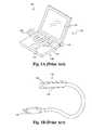
- FIG. 1Ashows a standard “clamshell” portable computer 100 .
- the clamshell portable computer 100comprises an viewing portion 110 having a screen 115 .
- the viewing portion 110is rotatably coupled to a processing, or base unit 120 .
- the base unit 120comprises a keyboard 125 and a trackpad 127 .
- the viewing portion 110 and the base unit 120are rotatably coupled by a hinge 130 , so that the computer 100 can be opened in a functional position or closed in a stowage position.
- a laptop computeris used in low levels of light. For example, the cabin lights of an airplane are generally dimmed or turned off during overnight flights.
- Some laptop computersare equipped with a backlighting for the keyboard 125 for providing illumination 128 of the keys for use in the dark. Although convenient, such backlighting adds thickness to the base unit 120 and requires several lighting sources, such as LEDs, for lighting individual keys, thereby depleting the battery more quickly and adding significant cost. Also, keyboard backlighting cannot illuminate any document or other material that the user of the laptop requires.
- FIG. 1Bshows a common external lighting device 150 .
- the external lighting device 150is connected to a laptop computer through a USB jack 155 to a USB port (not shown) of a laptop computer.
- the lighting device 150also draws power from the USB port.
- the external lighting device 150has a light fixture 160 generally comprising one or more LEDs 165 .
- the external lighting device 150is flexibly connected to the USB jack 155 so that the lighting fixture 160 can be position to direct light in any direction.
- the external lighting deviceis a discrete, external component that must be accounted for, separately stowed, and separately purchased. Furthermore, such devices either use up a USB port or require battery operation. Because of their general small size, they are easy to lose. Also, it can be inconvenient locating such a device in the dark when it is needed most.
- a portable computerhaving a positionable lighting fixture for providing light when ambient light is low, unavailable or inconvenient.
- the lighting fixturecan be positioned to illuminate the keyboard, other documents around the laptop, or the like.
- the lighting fixturecan be fixed in a stowage position when the laptop is closed or not in use.
- the lighting fixtureis a low cost integrated solution to backlit keyboards and external devices. Only one light source per fixture is needed rather than light sources for individual keys. Also, because the lighting fixture is integrated into the laptop, a user can quickly and conveniently illuminate the keyboard without searching for an external device when ambient light is low or not available.
- a portable computercomprises a user interface portion and a screen portion rotatably coupled to the user interface portion.
- the screen portioncomprises at least one light fixture positionably mounted to the screen portion.
- the light fixturecomprises an LED.
- the light fixtureis positionably mounted in one of a stowage position and a functional position. In a stowage position, the light fixture is flush with the substantially planar surface of the screen portion so that the laptop can be folded. In a functional position, the light fixture illuminates the user interface portion.
- light fixturecomprises a spring member.
- the spring membercan be made of any convenient material resilient to flex, such as plastic or metal. In a stowage position, the spring member is compressed against a housing or case of the screen portion and held in place by a latch member. The latch member is actuated by a user, which releases the tension on the compressed spring member, thereby relaxing the spring member into a steady state. When the spring member is relaxed, the light fixture is forced in a functional position.
- the light fixturecomprises a swivel member that enables 360 degree rotation of the light fixture.
- the swivel memberfurther comprises a concave housing for receiving a lens.
- the lensis generally round and convex in shape for diffusing the light from the LED to illuminate the entire keyboard.
- the swivel membercomprises a bracket, wherein the bracket has an opening having a diameter less than a diameter of the lens for retaining swivel member and effectuating a swivel motion.
- the swivel memberenables the light fixture to be pointed at the keyboard or slightly away in order to illuminate documents or the like adjacent to the laptop.
- a laptopcomprises a plurality of lighting fixtures, with some having a swivel member for full rotation and some having a spring member.
- FIG. 1Ashows a prior art portable computer.
- FIG. 1Bshows a prior art external lighting device.
- FIG. 2Ashows a portable computer having light fixtures in a stowage position per an embodiment of this invention.
- FIG. 2Bshows a portable computer having light fixtures in a functional position per an embodiment of this invention.
- FIGS. 2C and 2Dare a detailed view of a lighting fixture per an embodiment of this invention.
- FIG. 3is an exploded view of a lighting fixture per an embodiment of this invention.
- FIG. 4is an exploded view of a lighting fixture per an embodiment of this invention.
- FIG. 5Ais detailed view of a lighting fixture per an embodiment of this invention.
- FIG. 5Bis an exploded view of a lighting fixture per an embodiment of this invention.
- FIG. 5Cis operational view of a lighting fixture per an embodiment of this invention.
- FIGS. 2A and 2Bshow a laptop computer 202 having lighting fixtures 200 in stowage, or closed positions and open, or functional positions respectively.
- FIG. 2Ashows a laptop computer 202 that is open.
- the laptop computer 202comprises two lighting fixtures 200 that are in a stowage position.
- the lighting fixtures 200are flush with the surface of the screen portion 201 , so that the lighting fixtures 200 do not impede closing of the laptop computer 202 .
- FIG. 2Bshows the lighting fixtures 200 in an open, or functional position.
- the lighting fixtures 200are angled toward the user interface portion 203 with respect to the screen portion 201 such that the lighting fixtures 200 illuminate the user interface portion with light 205 .
- FIGS. 2C and 2Dshow the lighting fixture 200 positionably mounted to the screen portion 201 of a laptop in a stowage position and a functional position respectively.
- the lighting fixturecomprises an LED 240 for providing light, circuitry 230 for driving the LED 240 , and a lens 250 for diffusing the light provided by the LED.
- the lighting fixture 200is spring coupled and spring actuated.
- a spring member 210is affixed to a housing 220 .
- the spring member 210is preferably a flexible and resilient metal, such as plastic, metal, or any other suitable or convenient material.
- FIG. 2Ashows the lighting fixture 200 in a stowage position.
- the lighting fixture 200In a stowage position, the lighting fixture 200 is preferably substantially planar with respect to the screen portion 201 .
- the lighting fixture 200when the laptop is closed such that the screen portion 201 contacts the user interface portion (not shown), the lighting fixture 200 is recessed into the screen portion 201 and does not impede folding of the laptop computer.
- the spring member 210In the stowage position, the spring member 210 is compressed. Stated differently, the spring member is forced out of a steady state shape and therefore has stored energy.
- a latch member 260is provided to counter the stored energy within the spring member 210 and to affix the lighting fixture 200 in a stowage position.
- the latch member 260comprises a latching protrusion 265 that acts as a stop against the spring force of the spring member 210 when the latching protrusion 265 comes to rest against the housing 220 .
- FIG. 2Dshows the lighting fixture 200 in an open, or functional position. To place the lighting fixture 200 in the functional position, the latching member 260 can be actuated by a user by pressing against the tip of the latching member 260 thereby releasing the housing 220 from the stop against the latching protrusion 265 . The energy held in the spring member 210 will be released causing the lighting fixture 200 to move into the functional position.
- the spring member 210in its relaxed or steady state shown in FIG.
- the lens 250conforms around the case 204 of the screen portion 201 to hold the lighting fixture 200 in place in the functional position.
- the lens 250is angled toward the user interface portion (not shown). In the example provided, the lens 250 is angled at 60 degrees with respect to a plane defined by the surface of the screen portion 201 .
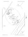
- FIG. 3shows an alternate embodiment of a lighting fixture 300 in an exploded view.
- the lighting fixture 300is based upon hinge assembly 310 that are affixed to a rigid member, such as the interior surface of the screen portion 301 .
- An LED 320is affixed to a circuitboard 330 .
- the circuitboard 330is coupled electrically to a battery (not shown) for providing power and a switch (not shown) for control.
- the LED 320 and circuitboard 330are mounted within a fitting 340 sized to receive the circuitboard 330 .
- the fittingcomprises an opening 345 corresponding to the location of the LED 320 on the circuitboard 330 to allow light to permeate therethrough.
- the fitting 340is held in position by a bracket 350 .
- the bracket 350comprises a notch 355 for receiving a locking protrusion 347 on the fitting 340 .
- the notch 355comprises a keep 356 for locking the locking protrusion 347 in place once sufficient force has been applied in an assembly process for forcing the locking protrusion 347 past the keep 356 and into the notch 355 .
- one notch 355is detailed, any number of notches can be used to secure the fitting 340 into the bracket 350 .
- the bracket 350further comprises a pair of hinge protrusions 357 on either side of the bracket 350 for mating with a pair of notches 315 on the hinge assembly 310 .
- the configuration of the hinge protrusions 357 on their respective sides mated with the notches 315effectuates a rotational motion of the lighting fixture 300 according to the axis of rotation 360 .
- the axis of rotation 360is substantially in the middle of the bracket and therefore in a complete assembly.
- a useris able to actuate the lighting fixture 300 to set to a desired angle to emit light to a desired area of the laptop (such as the keyboard) through an opening 370 in the exterior of the screen portion 301 by pushing on a lower portion of the lighting fixture 300 and causing a rotation in the lighting fixture 300 .
- the lighting fixture 300can be positioned so that it is flush with the surface of the screen portion 301 so that it does not encumber folding and stowing the laptop.
- a stop 317is included for restricting unwanted motion in an upward direction that may direct light into a users eyes.
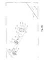
- FIG. 4shows an alternate embodiment of a hinge assembly 410 for effectuating a rotational motion in a lighting fixture 400 .
- the hinge assembly 410is affixed to a rigid member, such as the interior surface of the screen portion 401 .
- a housing 420is sized to receive a circuitboard 440 having an LED 430 .
- the housing 420comprises a bar 425 for mating with notches 415 on the hinge assembly 410 to effectuate a rotational motion according to the axis 470 .
- a lens 450is mounted onto the housing 420 for diffusing light emitted by the LED 430 through an opening 460 in the screen portion 401 .
- the opening 460comprises a groove 465 so that a user may insert a portion of their finger for actuating a rotational motion and placing the lighting fixture 400 in a functional position such that the LED emits light onto the user interface portion (not shown) or a stowage position such that the lens 450 is flush with the surface of the screen portion 401 .
- a stop 417restricts unwanted rotation in the X direction according to the axis 470 .
- the useractuates the lighting fixture 400 and causes rotation in the hinge by pushing downward on a top surface of the housing 420 and causing it to rotate forward along the axis 470 .
- FIGS. 5A , 5 B, and 5 Cshow an alternate embodiment of a portable computer lighting fixture 500 in cross section, exploded, and operational views respectively.
- an LED 520is affixed in a swivel housing 515 .
- the swivel housing 515has a round, convex external shape for effectuating a swivel motion against a swivel mount 512 .
- the swivel housing 515further comprises an interlocking feature 513 for receiving a lens 530 .
- the lens 530diffuses light provided by the LED 520 .
- the lens 530also has a round, convex external shape.
- the diameter of the swivel housing 515 and the lens 530should be the same.
- the swivel housing 515 and lens 530When coupled via the interlocking feature 513 , the swivel housing 515 and lens 530 have generally an ovoid cross section to enable a swiveling motion in any direction.
- a swivel bracket 540is provided for holding the swivel housing 515 and lens in a position.
- the swivel bracket 540comprises an opening 545 having an inner diameter 542 and an outer diameter 543 .
- the inner diameter 542is less than the diameter of the swivel housing 515 and lens 530 , so that the swivel housing 515 and lens 530 are maintained in a position without falling through the opening 545 .
- a usercan actuate the swivel housing through the opening 545 and orient the lens 530 in a desired direction.
- the swivel housing 515is not restricted with respect to orientation.
- the swivel housing 515comprises a stop 516 . The stop 516 comes into contact with the swivel mount 512 for stopping undesired motion of the swivel housing 515 . In the example provided, only one swivel mount 512 is shown.
- the mounting bracket 540comprises a plurality of mounting members 547 for mounting onto bosses 510 .
- the bosses 510are preferably affixed to the interior of the casing of the screen portion 501 .
- screw holes 546are provided however any method or means of affixing the mounting bracket 540 to the bosses 510 can be utilized.
- FIG. 5Cshows the portable computer lighting fixture 500 oriented in several directions.
- the swivel housing 515 /lens 530 combinationswivels freely between the swivel mount 512 of FIGS. 5A and 5B and the opening 545 of the swivel bracket 540 .
- the swivel housing 515 /lens 530 combinationshould be of a size to fit tight enough between the swivel bracket 540 and the swivel mount 512 such that the swivel housing 515 /lens 530 combination can remain in a position once an orientation has been selected. However, the fit should not be so tight that a user cannot easily orient the swivel housing 515 /lens 530 combination in another direction.
Landscapes
- Engineering & Computer Science (AREA)
- Computer Hardware Design (AREA)
- Physics & Mathematics (AREA)
- General Engineering & Computer Science (AREA)
- Theoretical Computer Science (AREA)
- Mathematical Physics (AREA)
- Human Computer Interaction (AREA)
- General Physics & Mathematics (AREA)
- Multimedia (AREA)
- Casings For Electric Apparatus (AREA)
- Fastening Of Light Sources Or Lamp Holders (AREA)
- Arrangement Of Elements, Cooling, Sealing, Or The Like Of Lighting Devices (AREA)
Abstract
Description
Claims (14)
Priority Applications (3)
| Application Number | Priority Date | Filing Date | Title |
|---|---|---|---|
| US12/971,599US8926111B2 (en) | 2010-12-17 | 2010-12-17 | Keyboard lighting device |
| PCT/US2011/064991WO2012082954A1 (en) | 2010-12-17 | 2011-12-14 | Keyboard lighting device |
| CN201180061280.1ACN103562633B (en) | 2010-12-17 | 2011-12-14 | A kind of portable computer |
Applications Claiming Priority (1)
| Application Number | Priority Date | Filing Date | Title |
|---|---|---|---|
| US12/971,599US8926111B2 (en) | 2010-12-17 | 2010-12-17 | Keyboard lighting device |
Publications (2)
| Publication Number | Publication Date |
|---|---|
| US20120155062A1 US20120155062A1 (en) | 2012-06-21 |
| US8926111B2true US8926111B2 (en) | 2015-01-06 |
Family
ID=46234151
Family Applications (1)
| Application Number | Title | Priority Date | Filing Date |
|---|---|---|---|
| US12/971,599Active2031-08-22US8926111B2 (en) | 2010-12-17 | 2010-12-17 | Keyboard lighting device |
Country Status (3)
| Country | Link |
|---|---|
| US (1) | US8926111B2 (en) |
| CN (1) | CN103562633B (en) |
| WO (1) | WO2012082954A1 (en) |
Cited By (4)
| Publication number | Priority date | Publication date | Assignee | Title |
|---|---|---|---|---|
| US20140218857A1 (en)* | 2013-02-04 | 2014-08-07 | Wistron Corporation | Portable electronic device |
| US11340662B2 (en)* | 2020-03-10 | 2022-05-24 | Compal Electronics, Inc. | Portable electronic device and disinfecting and sterilizing method thereof |
| US11409332B2 (en) | 2017-07-26 | 2022-08-09 | Apple Inc. | Computer with keyboard |
| US11500538B2 (en) | 2016-09-13 | 2022-11-15 | Apple Inc. | Keyless keyboard with force sensing and haptic feedback |
Families Citing this family (3)
| Publication number | Priority date | Publication date | Assignee | Title |
|---|---|---|---|---|
| TWI477952B (en)* | 2012-04-06 | 2015-03-21 | Compal Electronics Inc | Electronic device |
| WO2019231975A1 (en) | 2018-05-31 | 2019-12-05 | Bloom Energy Corporation | Cross-flow interconnect and fuel cell system including same |
| US12136756B1 (en) | 2020-04-02 | 2024-11-05 | Bloom Energy Corporation | Method of making a fuel cell stack with stress reducing seals |
Citations (48)
| Publication number | Priority date | Publication date | Assignee | Title |
|---|---|---|---|---|
| US3583734A (en) | 1969-01-13 | 1971-06-08 | Dominion Auto Access | Hinge joint assemblies |
| US4359487A (en) | 1980-07-11 | 1982-11-16 | Exxon Research And Engineering Co. | Method for applying an anti-reflection coating to a solar cell |
| US5903894A (en) | 1997-03-03 | 1999-05-11 | Microsoft Corporation | System and method for using a hierarchical data structure to control and identify devices and represent connections between the devices |
| US20010043188A1 (en)* | 1998-03-31 | 2001-11-22 | Atsunori Nakamura | Information terminal device with display-illuminating means |
| US20030202339A1 (en) | 2002-04-26 | 2003-10-30 | Oross Glen A. | Key for use in low light conditions |
| US6690585B2 (en) | 2001-08-29 | 2004-02-10 | Oqo, Inc. | Bi-directional DC power conversion system |
| US20050122671A1 (en) | 2003-12-09 | 2005-06-09 | Homer Steven S. | Electronic device with improved hinge |
| US6928464B2 (en) | 2001-04-30 | 2005-08-09 | Microsoft Corporation | Systems and methods for unified remote control access |
| US20050289266A1 (en) | 2004-06-08 | 2005-12-29 | Daniel Illowsky | Method and system for interoperable content player device engine |
| US6991350B2 (en)* | 2002-11-12 | 2006-01-31 | Delphitech Corporation | Housing for an LED fixture and soffit lighting system utilizing the same |
| US7054963B2 (en) | 2001-06-18 | 2006-05-30 | Betts-Lacroix Jonathan | Modular computing system |
| US7054965B2 (en) | 2003-03-18 | 2006-05-30 | Oqo Incorporated | Component for use as a portable computing device and pointing device |
| USD524809S1 (en) | 2004-12-07 | 2006-07-11 | Oqo, Inc. | Ultra personal computer with slidable monitor and thumb keyboard |
| US20060188096A1 (en) | 2004-02-27 | 2006-08-24 | Aguilar Joseph G | Systems and methods for remotely controlling computer applications |
| US20060224620A1 (en) | 2005-03-29 | 2006-10-05 | Microsoft Corporation | Automatic rules-based device synchronization |
| US20070024588A1 (en) | 2005-07-26 | 2007-02-01 | Yin Memphis Z | Keyboard lighting device |
| US20070124372A1 (en) | 2005-11-30 | 2007-05-31 | Microsoft Corporation | Using a mobile phone to control a personal computer |
| US20070146307A1 (en) | 2005-12-26 | 2007-06-28 | Hon Hai Precision Industry Co., Ltd. | Portable display device using electrophoretic display |
| US7247032B2 (en) | 2002-07-17 | 2007-07-24 | Oqo, Inc. | Electronic device with integral connectors |
| US7249873B2 (en)* | 2004-09-07 | 2007-07-31 | Lear Corporation | Adjustable light beam device for aimable vehicle lamp assembly and method |
| US7274355B2 (en) | 2003-04-25 | 2007-09-25 | Oqo, Inc. | Blended transfer function for computer pointing devices |
| US7285021B2 (en) | 2004-02-04 | 2007-10-23 | Oqo, Inc. | Docking cable |
| US7352332B1 (en) | 2004-09-22 | 2008-04-01 | Oqo, Inc. | Multiple disparate wireless units sharing of antennas |
| US7353053B2 (en) | 2004-11-23 | 2008-04-01 | Oqo, Inc. | Non-binding sliding display for a handheld electronic device |
| US7372454B2 (en) | 2001-10-29 | 2008-05-13 | Oqo Incorporated | Keyboard with variable-sized keys |
| US20080112113A1 (en) | 2006-11-14 | 2008-05-15 | Motorola, Inc. | Portable electronic device including hinge assembly with user interface element |
| US20080180391A1 (en) | 2007-01-11 | 2008-07-31 | Joseph Auciello | Configurable electronic interface |
| USD579451S1 (en) | 2007-01-05 | 2008-10-28 | Oqo, Inc. | Computer docking assembly |
| US20080266865A1 (en)* | 2007-04-24 | 2008-10-30 | Lev Jeffrey A | Electronic device illuminator |
| USD581935S1 (en) | 2008-01-07 | 2008-12-02 | Oqo, Inc. | Keyboard for hand held computing device |
| US7493500B2 (en) | 2003-03-07 | 2009-02-17 | Oqo, Incorporated | Personal computing device having single-cell battery |
| US7518860B2 (en) | 2005-10-14 | 2009-04-14 | Oqo, Inc. | Combined outflow portal for acoustic and thermal energy |
| US20090109649A1 (en) | 2007-10-30 | 2009-04-30 | General Dynamics Itronix Corporation | System and apparatus for keyboard illumination |
| US20090166493A1 (en)* | 2007-12-26 | 2009-07-02 | Hon Hai Precision Industry Co., Ltd. | Electronic device with lighting apparatus |
| US7572021B2 (en)* | 2006-01-27 | 2009-08-11 | Hoya Corporation | LED unit with annular mounting structure and mounting method thereof |
| WO2009116996A1 (en)* | 2008-03-19 | 2009-09-24 | Hewlett-Packard Development Company, L.P. | Computing devices having adjustable keyboard lights |
| USD602938S1 (en) | 2007-06-05 | 2009-10-27 | Oqo, Inc. | Open-configured computer docking assembly with two pivot arms |
| US20090268401A1 (en)* | 2004-03-12 | 2009-10-29 | Apple Inc. | Camera latch |
| US20100042671A1 (en) | 2008-08-14 | 2010-02-18 | Symbol Technologies, Inc. | Server embedded in device charging cradle |
| WO2010021626A1 (en) | 2008-08-21 | 2010-02-25 | Hewlett-Packard Development Company, L.P. | Computer with integrated light |
| US20100064536A1 (en) | 2008-09-08 | 2010-03-18 | Qualcomm Incorporated | Multi-panel electronic device |
| US7765326B2 (en) | 2001-10-22 | 2010-07-27 | Apple Inc. | Intelligent interaction between media player and host computer |
| US7810222B2 (en) | 2007-01-05 | 2010-10-12 | Zetta Research, Llc | Method for protecting a connection interface in a computer-docking assembly |
| US8021022B2 (en)* | 2008-07-10 | 2011-09-20 | Compal Electronics, Inc. | Lighting structure |
| USD652832S1 (en) | 2011-02-24 | 2012-01-24 | Imerj LLC | Dual screen personal computer |
| US8111040B2 (en) | 2004-02-17 | 2012-02-07 | Research In Motion Limited | Method and apparatus for handling a charging state in a mobile electronic device |
| US8223487B2 (en)* | 2010-01-26 | 2012-07-17 | Compal Electronics, Inc. | Electronic device |
| US8353048B1 (en) | 2006-07-31 | 2013-01-08 | Sprint Communications Company L.P. | Application digital rights management (DRM) and portability using a mobile device for authentication |
Family Cites Families (2)
| Publication number | Priority date | Publication date | Assignee | Title |
|---|---|---|---|---|
| CN2765050Y (en)* | 2005-02-24 | 2006-03-15 | 廖金波 | lighting device |
| CN2862152Y (en)* | 2005-09-16 | 2007-01-24 | 纬创资通股份有限公司 | Light source device, display module and foldable electronic device having the device |
- 2010
- 2010-12-17USUS12/971,599patent/US8926111B2/enactiveActive
- 2011
- 2011-12-14CNCN201180061280.1Apatent/CN103562633B/enactiveActive
- 2011-12-14WOPCT/US2011/064991patent/WO2012082954A1/enactiveApplication Filing
Patent Citations (54)
| Publication number | Priority date | Publication date | Assignee | Title |
|---|---|---|---|---|
| US3583734A (en) | 1969-01-13 | 1971-06-08 | Dominion Auto Access | Hinge joint assemblies |
| US4359487A (en) | 1980-07-11 | 1982-11-16 | Exxon Research And Engineering Co. | Method for applying an anti-reflection coating to a solar cell |
| US5903894A (en) | 1997-03-03 | 1999-05-11 | Microsoft Corporation | System and method for using a hierarchical data structure to control and identify devices and represent connections between the devices |
| US20010043188A1 (en)* | 1998-03-31 | 2001-11-22 | Atsunori Nakamura | Information terminal device with display-illuminating means |
| US6928464B2 (en) | 2001-04-30 | 2005-08-09 | Microsoft Corporation | Systems and methods for unified remote control access |
| US7054963B2 (en) | 2001-06-18 | 2006-05-30 | Betts-Lacroix Jonathan | Modular computing system |
| US6690585B2 (en) | 2001-08-29 | 2004-02-10 | Oqo, Inc. | Bi-directional DC power conversion system |
| US7765326B2 (en) | 2001-10-22 | 2010-07-27 | Apple Inc. | Intelligent interaction between media player and host computer |
| US7372454B2 (en) | 2001-10-29 | 2008-05-13 | Oqo Incorporated | Keyboard with variable-sized keys |
| US20030202339A1 (en) | 2002-04-26 | 2003-10-30 | Oross Glen A. | Key for use in low light conditions |
| US7390197B2 (en) | 2002-07-17 | 2008-06-24 | Oqo Incorporated | Electronic device with integral connectors |
| US7247032B2 (en) | 2002-07-17 | 2007-07-24 | Oqo, Inc. | Electronic device with integral connectors |
| US7357648B2 (en) | 2002-07-17 | 2008-04-15 | Oqo, Inc. | Electronic device with integral connectors |
| US6991350B2 (en)* | 2002-11-12 | 2006-01-31 | Delphitech Corporation | Housing for an LED fixture and soffit lighting system utilizing the same |
| US7493500B2 (en) | 2003-03-07 | 2009-02-17 | Oqo, Incorporated | Personal computing device having single-cell battery |
| US7054965B2 (en) | 2003-03-18 | 2006-05-30 | Oqo Incorporated | Component for use as a portable computing device and pointing device |
| US7274355B2 (en) | 2003-04-25 | 2007-09-25 | Oqo, Inc. | Blended transfer function for computer pointing devices |
| US20050122671A1 (en) | 2003-12-09 | 2005-06-09 | Homer Steven S. | Electronic device with improved hinge |
| US7285021B2 (en) | 2004-02-04 | 2007-10-23 | Oqo, Inc. | Docking cable |
| US7537485B2 (en) | 2004-02-04 | 2009-05-26 | Oqo Incorporated | Docking Cable |
| US7462073B2 (en) | 2004-02-04 | 2008-12-09 | Oqo Incorporated | Docking module comprising a DC-DC charger |
| US8111040B2 (en) | 2004-02-17 | 2012-02-07 | Research In Motion Limited | Method and apparatus for handling a charging state in a mobile electronic device |
| US20060188096A1 (en) | 2004-02-27 | 2006-08-24 | Aguilar Joseph G | Systems and methods for remotely controlling computer applications |
| US20090268401A1 (en)* | 2004-03-12 | 2009-10-29 | Apple Inc. | Camera latch |
| US20050289266A1 (en) | 2004-06-08 | 2005-12-29 | Daniel Illowsky | Method and system for interoperable content player device engine |
| US7249873B2 (en)* | 2004-09-07 | 2007-07-31 | Lear Corporation | Adjustable light beam device for aimable vehicle lamp assembly and method |
| US7352332B1 (en) | 2004-09-22 | 2008-04-01 | Oqo, Inc. | Multiple disparate wireless units sharing of antennas |
| US7353053B2 (en) | 2004-11-23 | 2008-04-01 | Oqo, Inc. | Non-binding sliding display for a handheld electronic device |
| USD524809S1 (en) | 2004-12-07 | 2006-07-11 | Oqo, Inc. | Ultra personal computer with slidable monitor and thumb keyboard |
| US20060224620A1 (en) | 2005-03-29 | 2006-10-05 | Microsoft Corporation | Automatic rules-based device synchronization |
| US20070024588A1 (en) | 2005-07-26 | 2007-02-01 | Yin Memphis Z | Keyboard lighting device |
| US7518860B2 (en) | 2005-10-14 | 2009-04-14 | Oqo, Inc. | Combined outflow portal for acoustic and thermal energy |
| US20070124372A1 (en) | 2005-11-30 | 2007-05-31 | Microsoft Corporation | Using a mobile phone to control a personal computer |
| US20070146307A1 (en) | 2005-12-26 | 2007-06-28 | Hon Hai Precision Industry Co., Ltd. | Portable display device using electrophoretic display |
| US7572021B2 (en)* | 2006-01-27 | 2009-08-11 | Hoya Corporation | LED unit with annular mounting structure and mounting method thereof |
| US8353048B1 (en) | 2006-07-31 | 2013-01-08 | Sprint Communications Company L.P. | Application digital rights management (DRM) and portability using a mobile device for authentication |
| US20080112113A1 (en) | 2006-11-14 | 2008-05-15 | Motorola, Inc. | Portable electronic device including hinge assembly with user interface element |
| US7810222B2 (en) | 2007-01-05 | 2010-10-12 | Zetta Research, Llc | Method for protecting a connection interface in a computer-docking assembly |
| USD579451S1 (en) | 2007-01-05 | 2008-10-28 | Oqo, Inc. | Computer docking assembly |
| US20080180391A1 (en) | 2007-01-11 | 2008-07-31 | Joseph Auciello | Configurable electronic interface |
| US20080266865A1 (en)* | 2007-04-24 | 2008-10-30 | Lev Jeffrey A | Electronic device illuminator |
| USD602938S1 (en) | 2007-06-05 | 2009-10-27 | Oqo, Inc. | Open-configured computer docking assembly with two pivot arms |
| US20090109649A1 (en) | 2007-10-30 | 2009-04-30 | General Dynamics Itronix Corporation | System and apparatus for keyboard illumination |
| US20090166493A1 (en)* | 2007-12-26 | 2009-07-02 | Hon Hai Precision Industry Co., Ltd. | Electronic device with lighting apparatus |
| US7794113B2 (en)* | 2007-12-26 | 2010-09-14 | Hon Hai Precision Industry Co., Ltd. | Electronic device with lighting apparatus |
| USD581935S1 (en) | 2008-01-07 | 2008-12-02 | Oqo, Inc. | Keyboard for hand held computing device |
| WO2009116996A1 (en)* | 2008-03-19 | 2009-09-24 | Hewlett-Packard Development Company, L.P. | Computing devices having adjustable keyboard lights |
| US8567995B2 (en)* | 2008-03-19 | 2013-10-29 | Hewlett-Packard Development Company, L.P. | Computing devices having adjustable keyboard lights |
| US8021022B2 (en)* | 2008-07-10 | 2011-09-20 | Compal Electronics, Inc. | Lighting structure |
| US20100042671A1 (en) | 2008-08-14 | 2010-02-18 | Symbol Technologies, Inc. | Server embedded in device charging cradle |
| WO2010021626A1 (en) | 2008-08-21 | 2010-02-25 | Hewlett-Packard Development Company, L.P. | Computer with integrated light |
| US20100064536A1 (en) | 2008-09-08 | 2010-03-18 | Qualcomm Incorporated | Multi-panel electronic device |
| US8223487B2 (en)* | 2010-01-26 | 2012-07-17 | Compal Electronics, Inc. | Electronic device |
| USD652832S1 (en) | 2011-02-24 | 2012-01-24 | Imerj LLC | Dual screen personal computer |
Non-Patent Citations (1)
| Title |
|---|
| International Search Report dated May 1, 2012, International Application No. PCT/US11/64991, International filed: Dec. 14, 2011, authorized officer Lee W. Young, 11 pages. |
Cited By (7)
| Publication number | Priority date | Publication date | Assignee | Title |
|---|---|---|---|---|
| US20140218857A1 (en)* | 2013-02-04 | 2014-08-07 | Wistron Corporation | Portable electronic device |
| US9195275B2 (en)* | 2013-02-04 | 2015-11-24 | Wistron Corporation | Portable electronic device |
| US11500538B2 (en) | 2016-09-13 | 2022-11-15 | Apple Inc. | Keyless keyboard with force sensing and haptic feedback |
| US11409332B2 (en) | 2017-07-26 | 2022-08-09 | Apple Inc. | Computer with keyboard |
| US11619976B2 (en) | 2017-07-26 | 2023-04-04 | Apple Inc. | Computer with keyboard |
| US12079043B2 (en) | 2017-07-26 | 2024-09-03 | Apple Inc. | Computer with keyboard |
| US11340662B2 (en)* | 2020-03-10 | 2022-05-24 | Compal Electronics, Inc. | Portable electronic device and disinfecting and sterilizing method thereof |
Also Published As
| Publication number | Publication date |
|---|---|
| WO2012082954A1 (en) | 2012-06-21 |
| US20120155062A1 (en) | 2012-06-21 |
| CN103562633B (en) | 2019-01-11 |
| CN103562633A (en) | 2014-02-05 |
Similar Documents
| Publication | Publication Date | Title |
|---|---|---|
| US8926111B2 (en) | Keyboard lighting device | |
| CN101689063B (en) | Electronic equipment illuminator | |
| CN218669856U (en) | Supporting seat, fan and lamp | |
| US9614338B2 (en) | Power module having multiple power receptacles | |
| US8223487B2 (en) | Electronic device | |
| CN107531178B (en) | lighting device | |
| US20040062033A1 (en) | Keypad illuminating system for a data processing device | |
| US8517560B2 (en) | Portable multi-purpose illumination device | |
| TW200809465A (en) | Electronic apparatus | |
| KR20070101146A (en) | Electronic device | |
| US20120281421A1 (en) | Portable illumination device | |
| US20170248291A1 (en) | Rotatable illuminator | |
| CN101283216A (en) | portable illuminator | |
| US20070166019A1 (en) | Information processing apparatus | |
| JP7029690B2 (en) | Indicator light and transmitter with indicator light | |
| US11674648B2 (en) | Lighting fixture | |
| HU223784B1 (en) | Computer with illuminator for keyboard | |
| TWI388764B (en) | Illumination device and operation method thereof and electronic apparatus using the same | |
| KR20200081860A (en) | Folder type portable lamp | |
| US20070091593A1 (en) | Positionable flashlight with dual light sources | |
| JP2020098758A (en) | Illuminating device | |
| WO2012121126A1 (en) | Led illumination device | |
| CN210373188U (en) | An LED desk lamp | |
| US7780319B2 (en) | Computer panel with light-adjusting mechanism | |
| CN204153484U (en) | Head-mounted lighting device with multiple projection angles |
Legal Events
| Date | Code | Title | Description |
|---|---|---|---|
| AS | Assignment | Owner name:FLEXTRONICS ID, LLC, COLORADO Free format text:ASSIGNMENT OF ASSIGNORS INTEREST;ASSIGNOR:WENG, CHUNG-KUO;REEL/FRAME:025518/0740 Effective date:20101213 | |
| AS | Assignment | Owner name:IMERJ LLC, COLORADO Free format text:CHANGE OF NAME;ASSIGNOR:FLEXTRONICS ID, LLC;REEL/FRAME:026165/0613 Effective date:20110329 | |
| AS | Assignment | Owner name:Z124, CAYMAN ISLANDS Free format text:ASSIGNMENT OF ASSIGNORS INTEREST;ASSIGNOR:IMERJ, LLC;REEL/FRAME:028323/0090 Effective date:20120605 | |
| AS | Assignment | Owner name:FLEXTRONICS AP, LLC, COLORADO Free format text:ASSIGNMENT OF ASSIGNORS INTEREST;ASSIGNOR:FLEXTRONICS ID, LLC;REEL/FRAME:030618/0785 Effective date:20130613 | |
| AS | Assignment | Owner name:Z124, CAYMAN ISLANDS Free format text:CORRECTION BY DECLARATION OF IONCORRECT # 12971599 RECORDED AT REEL 030615 FRAME 0785;ASSIGNOR:Z124;REEL/FRAME:032076/0487 Effective date:20130729 | |
| STCF | Information on status: patent grant | Free format text:PATENTED CASE | |
| FEPP | Fee payment procedure | Free format text:SURCHARGE FOR LATE PAYMENT, LARGE ENTITY (ORIGINAL EVENT CODE: M1554) | |
| MAFP | Maintenance fee payment | Free format text:PAYMENT OF MAINTENANCE FEE, 4TH YEAR, LARGE ENTITY (ORIGINAL EVENT CODE: M1551) Year of fee payment:4 | |
| MAFP | Maintenance fee payment | Free format text:PAYMENT OF MAINTENANCE FEE, 8TH YEAR, LARGE ENTITY (ORIGINAL EVENT CODE: M1552); ENTITY STATUS OF PATENT OWNER: LARGE ENTITY Year of fee payment:8 |