US8925931B2 - Oscillating tool - Google Patents
Oscillating toolDownload PDFInfo
- Publication number
- US8925931B2 US8925931B2US12/942,098US94209810AUS8925931B2US 8925931 B2US8925931 B2US 8925931B2US 94209810 AUS94209810 AUS 94209810AUS 8925931 B2US8925931 B2US 8925931B2
- Authority
- US
- United States
- Prior art keywords
- clamp
- accessory
- arrangement
- clamp assembly
- tool body
- Prior art date
- Legal status (The legal status is an assumption and is not a legal conclusion. Google has not performed a legal analysis and makes no representation as to the accuracy of the status listed.)
- Active, expires
Links
Images


Classifications
- B—PERFORMING OPERATIONS; TRANSPORTING
- B24—GRINDING; POLISHING
- B24B—MACHINES, DEVICES, OR PROCESSES FOR GRINDING OR POLISHING; DRESSING OR CONDITIONING OF ABRADING SURFACES; FEEDING OF GRINDING, POLISHING, OR LAPPING AGENTS
- B24B23/00—Portable grinding machines, e.g. hand-guided; Accessories therefor
- B24B23/04—Portable grinding machines, e.g. hand-guided; Accessories therefor with oscillating grinding tools; Accessories therefor
- B—PERFORMING OPERATIONS; TRANSPORTING
- B23—MACHINE TOOLS; METAL-WORKING NOT OTHERWISE PROVIDED FOR
- B23B—TURNING; BORING
- B23B31/00—Chucks; Expansion mandrels; Adaptations thereof for remote control
- B23B31/02—Chucks
- B23B31/10—Chucks characterised by the retaining or gripping devices or their immediate operating means
- B—PERFORMING OPERATIONS; TRANSPORTING
- B24—GRINDING; POLISHING
- B24B—MACHINES, DEVICES, OR PROCESSES FOR GRINDING OR POLISHING; DRESSING OR CONDITIONING OF ABRADING SURFACES; FEEDING OF GRINDING, POLISHING, OR LAPPING AGENTS
- B24B45/00—Means for securing grinding wheels on rotary arbors
- B24B45/006—Quick mount and release means for disc-like wheels, e.g. on power tools
- B—PERFORMING OPERATIONS; TRANSPORTING
- B27—WORKING OR PRESERVING WOOD OR SIMILAR MATERIAL; NAILING OR STAPLING MACHINES IN GENERAL
- B27B—SAWS FOR WOOD OR SIMILAR MATERIAL; COMPONENTS OR ACCESSORIES THEREFOR
- B27B19/00—Other reciprocating saws with power drive; Fret-saws
- B27B19/006—Other reciprocating saws with power drive; Fret-saws with oscillating saw blades; Hand saws with oscillating saw blades
- B—PERFORMING OPERATIONS; TRANSPORTING
- B27—WORKING OR PRESERVING WOOD OR SIMILAR MATERIAL; NAILING OR STAPLING MACHINES IN GENERAL
- B27B—SAWS FOR WOOD OR SIMILAR MATERIAL; COMPONENTS OR ACCESSORIES THEREFOR
- B27B5/00—Sawing machines working with circular or cylindrical saw blades; Components or equipment therefor
- B27B5/29—Details; Component parts; Accessories
- B27B5/30—Details; Component parts; Accessories for mounting or securing saw blades or saw spindles
- B27B5/32—Devices for securing circular saw blades to the saw spindle
- Y—GENERAL TAGGING OF NEW TECHNOLOGICAL DEVELOPMENTS; GENERAL TAGGING OF CROSS-SECTIONAL TECHNOLOGIES SPANNING OVER SEVERAL SECTIONS OF THE IPC; TECHNICAL SUBJECTS COVERED BY FORMER USPC CROSS-REFERENCE ART COLLECTIONS [XRACs] AND DIGESTS
- Y10—TECHNICAL SUBJECTS COVERED BY FORMER USPC
- Y10T—TECHNICAL SUBJECTS COVERED BY FORMER US CLASSIFICATION
- Y10T279/00—Chucks or sockets
- Y10T279/18—Pivoted jaw
- Y—GENERAL TAGGING OF NEW TECHNOLOGICAL DEVELOPMENTS; GENERAL TAGGING OF CROSS-SECTIONAL TECHNOLOGIES SPANNING OVER SEVERAL SECTIONS OF THE IPC; TECHNICAL SUBJECTS COVERED BY FORMER USPC CROSS-REFERENCE ART COLLECTIONS [XRACs] AND DIGESTS
- Y10—TECHNICAL SUBJECTS COVERED BY FORMER USPC
- Y10T—TECHNICAL SUBJECTS COVERED BY FORMER US CLASSIFICATION
- Y10T279/00—Chucks or sockets
- Y10T279/33—Member applies axial force component
- Y—GENERAL TAGGING OF NEW TECHNOLOGICAL DEVELOPMENTS; GENERAL TAGGING OF CROSS-SECTIONAL TECHNOLOGIES SPANNING OVER SEVERAL SECTIONS OF THE IPC; TECHNICAL SUBJECTS COVERED BY FORMER USPC CROSS-REFERENCE ART COLLECTIONS [XRACs] AND DIGESTS
- Y10—TECHNICAL SUBJECTS COVERED BY FORMER USPC
- Y10T—TECHNICAL SUBJECTS COVERED BY FORMER US CLASSIFICATION
- Y10T279/00—Chucks or sockets
- Y10T279/34—Accessory or component
- Y10T279/3431—Chuck key
- Y10T279/3451—Nonseparable or built-in
- Y—GENERAL TAGGING OF NEW TECHNOLOGICAL DEVELOPMENTS; GENERAL TAGGING OF CROSS-SECTIONAL TECHNOLOGIES SPANNING OVER SEVERAL SECTIONS OF THE IPC; TECHNICAL SUBJECTS COVERED BY FORMER USPC CROSS-REFERENCE ART COLLECTIONS [XRACs] AND DIGESTS
- Y10—TECHNICAL SUBJECTS COVERED BY FORMER USPC
- Y10T—TECHNICAL SUBJECTS COVERED BY FORMER US CLASSIFICATION
- Y10T83/00—Cutting
- Y10T83/687—By tool reciprocable along elongated edge
- Y10T83/7045—Arcuately oscillating tool carried on single pivot
- Y—GENERAL TAGGING OF NEW TECHNOLOGICAL DEVELOPMENTS; GENERAL TAGGING OF CROSS-SECTIONAL TECHNOLOGIES SPANNING OVER SEVERAL SECTIONS OF THE IPC; TECHNICAL SUBJECTS COVERED BY FORMER USPC CROSS-REFERENCE ART COLLECTIONS [XRACs] AND DIGESTS
- Y10—TECHNICAL SUBJECTS COVERED BY FORMER USPC
- Y10T—TECHNICAL SUBJECTS COVERED BY FORMER US CLASSIFICATION
- Y10T83/00—Cutting
- Y10T83/929—Tool or tool with support
- Y10T83/9457—Joint or connection
- Y10T83/9464—For rotary tool
Definitions
- the present disclosurerelates to power hand tools and more specifically to a clamp arrangement for releasably securing an accessory to an oscillating power hand tool.
- Power hand toolsare provided in many examples for performing a wide range of tasks.
- some power hand toolscan include an output member that is driven by a motor and that couples with an accessory to perform a working operation onto a work piece.
- some hand toolscan provide various configurations for attaching cutting accessories, grinding accessories, sanding accessories and the like.
- Some power hand toolsare configured as oscillating tools that are operable to transmit an oscillating motion onto the accessory.
- a usermay want to exchange one accessory for another accessory. For example, a user may want to exchange one grinding accessory with another grinding accessory or one sanding platen with another sanding platen. Alternatively, a user may wish to replace a cutting accessory with another cutting accessory. It is also contemplated that a user may want to replace a given accessory dedicated to one task (such as sanding) with another accessory dedicated toward another task (such as cutting for example).
- many power hand toolsrequire the use of a secondary tool to swap out accessories. For example, many power hand tools require the use of a hand screw driver that can be used to retract a fastener that may lock the accessory to the output member of the power hand tool. In other examples, a wrench or other hand tool may be required to remove or unlock a given accessory from the power hand tool and subsequently lock another accessory back to the power hand tool.
- a clamp arrangement for releasably securing an accessory to a power toolcan include a tool body including a motor that drives an output member.
- a clamp assemblycan include a first clamp member that moves relative to the accessory between a closed position wherein the clamp assembly retains the accessory and an open position wherein the first clamp member of the clamp assembly is offset from the accessory permitting removal of the accessory from the clamp assembly.
- a levercan have a user engagement portion and a pivot portion including a pivot axle. The lever can be pivotally coupled to the tool body about the pivot axle between a first position, wherein the clamp assembly is in the closed position and a second position wherein movement of the user engagement portion of the lever causes the clamp assembly to be moved to the open position.
- the user engagement portion of the levercan be positioned intermediate the tool housing and the accessory.
- the accessorycan oscillate about a longitudinal axis that is located intermediate the pivot axle and the user engagement portion.
- a first biasing membercan bias the clamp assembly toward the closed position.
- the clamp assemblycan further comprise a second clamp member having a first portion that opposes the first clamp member and cooperates with the first clamp member to clamp the accessory between the first and second clamp members.
- the first clamp membercan include a first clamp body having one of a first plurality of protrusions extending from a first clamping surface and a first plurality of recesses formed into the first clamping surface.
- the second clamp membercan include a second clamp body that has a second clamping surface that opposes the first clamping surface.
- the second clamping surfacecan include the other of the first plurality of protrusions and first plurality of recesses, wherein the first plurality of protrusions are configured to cooperatively locate into the corresponding first plurality of recesses in the closed position.
- the first clamp bodycan include an annular flange that nests in a pocket formed on the lever.
- the second clamp bodycan further include an auxiliary attachment surface that is distinct from the second clamping surface.
- the auxiliary attachment surfacecan be configured to selectively and alternatively connect with a secondary accessory.
- the auxiliary attachment surfacecan further include one of a second plurality of protrusions and second plurality of recesses thereon that are configured to cooperatively mate with the secondary accessory.
- the second clamping surface and the auxiliary attachment surfacecan face away from each other.
- a second biasing membercan be disposed between the user engagement portion of the lever and the tool body. The second biasing member can bias the user engagement portion of the lever away from the tool body.
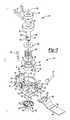
- FIG. 1is a perspective view of a clamp arrangement constructed in accordance to one example of the present teachings and shown operatively associated with an exemplary power hand tool for releasably securing a first or a second accessory;
- FIG. 2is a perspective view of a clamp assembly of the clamp arrangement shown in FIG. 1 and shown with the clamp assembly in the closed position retaining the first accessory;
- FIG. 3is an exploded perspective view of the clamp assembly of FIG. 2 ;
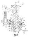
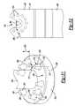
- FIG. 4is a sectional view of the clamp assembly of FIG. 2 and shown with the clamp assembly in the closed position and a lever of the clamp assembly in a first position;
- FIG. 5is a cross-sectional view of the clamp assembly of FIG. 4 and shown with the clamp assembly in the open position resulting from the lever being rotated about a pivot axle into a second position wherein the first accessory is subsequently lifted out of engagement with the first clamp member;
- FIG. 6is a cross-sectional view of the clamp assembly of FIG. 5 shown with the clamp assembly in the open position and the lever in the second position and illustrating the first accessory being removed from the clamp assembly;
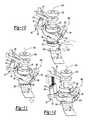
- FIGS. 7-9are perspective views of the clamp assembly that generally correspond to the sequence illustrated in FIGS. 4-6 for removing the first accessory from the clamp assembly;
- FIGS. 10-12are perspective views of the clamp assembly that illustrate an exemplary sequence of orienting the first accessory in a different rotational position relative to the clamp assembly;
- FIGS. 13-15are cross-sectional views of the clamp assembly taken through a spindle of the power hand tool and shown with the first accessory rotated at different positions around an axis of the spindle;
- FIG. 16is a perspective view of the clamp arrangement of the present teachings and shown with the clamp assembly secured to the second accessory;
- FIG. 17is an exploded perspective view of the clamp assembly and second accessory illustrated in FIG. 16 ;
- FIG. 18is a sectional view of the clamp assembly of FIG. 16 and shown with the clamp assembly in the open position resulting from movement of the lever around the pivot axle to the second position for receipt of a mounting collar of the second accessory;
- FIG. 19is a cross-sectional view of the clamp assembly of FIG. 18 and shown with the mounting collar of the second accessory positioned generally between first and second clamp members of the clamp assembly while the lever is maintained in the second position;
- FIG. 20is a cross-sectional view of the clamp assembly of FIG. 19 and illustrating the clamp assembly in the closed position as a result of the lever being released and returned to the first position causing the first and second clamp members to clamp the mounting collar;
- FIG. 21is a perspective view of an exemplary third accessory
- FIG. 22is a partial cross-section of the clamp assembly and shown with the third accessory secured to an auxiliary mounting surface of the second clamp member;
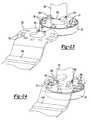
- FIGS. 23-25illustrate an exemplary assembly sequence of a fourth accessory having a throat that defines a relatively narrower opening as compared to the first accessory wherein the throat is slidably directed through channels provided on the spindle;
- FIG. 26is an exploded partial plan view of the fourth accessory and shown adjacent to the second clamp member and illustrated with the spindle in cross-section taken through the channels;
- FIG. 27is a partial plan view of a fifth accessory having circular mounting passages according to additional features.
- FIG. 28is a partial plan view of the fifth accessory shown in FIG. 27 and illustrated interfacing with the second clamp member;
- FIG. 29is a side view of a clamp arrangement constructed in accordance to another example of the present teachings and shown operatively associated with an exemplary hand tool;
- FIG. 30is a sectional view of the clamp assembly of FIG. 29 and shown with the clamp assembly in a closed position and a lever of the clamp assembly in a first position;
- FIG. 31is a perspective view of the second clamp member of the clamp assembly of FIG. 30 ;
- FIG. 32is a plan view of an accessory constructed in accordance to one example of the present teachings.
- FIG. 33is a side view of the accessory of FIG. 32 shown placed on the second clamp member and shown with the first clamp member removed for illustrative purposes;
- FIG. 34is a side view of the clamp assembly shown during removal of the accessory where the lever is moved from the first position (phantom) to a second position (solid line) and the first clamp member is raised away from engagement with the accessory.
- a clamp arrangement constructed in accordance to one example of the present disclosureis shown and generally identified at reference numeral 10 .
- the clamp arrangement 10is shown operatively associated with a power tool 12 for selectively and alternatively retaining various accessories, such as a first accessory 14 a or a second accessory 14 b .
- the exemplary power toolcan generally include a tool body 18 including a housing 20 that generally contains a motor 22 that drives an output member 24 .
- the output member 24can be coupled to a spindle 26 .
- the exemplary power tool 12is configured for providing an oscillating motion onto the spindle 26 . It will be appreciated that while the clamp arrangement 10 is disclosed herein as part of an oscillating power hand tool, the clamp arrangement 10 may be also configured for use with other power tools that releasably secure an accessory.
- the clamp arrangement 10can further include a clamp assembly 30 that operatively cooperates with an actuator such as a lever 32 .
- the clamp assembly 30can generally include a first clamp member 36 and a second clamp member 38 .
- the lever 32can include a lever arm 40 that includes a user engagement portion 42 and a block 44 .
- the lever 32can further include a pivot portion 46 having a pivot axle 48 .
- the second accessory 14 bcan generally include a sanding platen 50 having a platen body 52 and a mounting collar 54 .
- the mounting collar 54can be coupled to the body 52 by way of a series of fasteners 56 .
- the body 52can be configured to support an abrasive sheet, such as sand paper and the like as is known in the art.
- the mounting collar 54can generally include an upper plate portion 60 having a plurality of mounting features 62 .
- the mounting features 62are generally in the form of passages formed through the mounting collar 54 .
- the mounting collar 54can generally include an open-ended aperture or throat 66 configured to accept the spindle 26 in an assembled position as will be described herein.
- the second clamp member 38can include a second clamp body 70 generally in the form of a ring having a central opening 72 .
- the second clamp body 70can generally comprise a second clamping surface 74 having a plurality of mounting features 76 formed thereon.
- the plurality of mounting features 76are in the form of male protrusions 78 .
- eight protrusions each having a tapered shape or formare provided.
- the second clamp body 70can additionally include an auxiliary attachment surface 80 having a plurality of auxiliary mounting features 82 ( FIG. 2 ).
- auxiliary mounting features 82are shown in the form of male protrusions and may include a similar eight protrusion configuration as provided on the second clamping surface 74 .
- the auxiliary mounting features 82can each have a diameter of 2.4 mm. Other configurations are contemplated.
- the first clamp member 36can generally include a first clamp member body 84 having an annular flange 86 .
- the first clamp member body 84can include a first clamping surface 87 having a plurality of mounting features 88 ( FIG. 4 ).
- the plurality of mounting features 88are in the form of recesses that cooperatively receive the corresponding plurality of mounting features 76 of the second clamp member 38 .
- the mounting features 88can have any configuration, such as blind bores, or circular grooves being suitable to accept the male protrusions of the mounting features 76 .
- the annular flange 86can generally extend radially on an end of an outer hub 90 of the first clamp member body 84 .
- the annular flange 86can have a lever opposing surface 91 .
- the first clamp member body 84can further include an inner hub 92 that defines a first clamp member opening 94 .
- the first clamp member opening 94can be configured to receive the spindle 26 .
- An annular channel 96can be formed between the outer hub 90 and the inner hub 92 .
- the annular channel 96can have a terminal surface 98 .
- the lever 32can generally include a lever body 100 having the user engagement portion 42 formed generally on a first end and the pivot portion 46 formed on an opposite end.
- the pivot portion 46can generally include a pair of lobes 102 that each define an axle passage 104 .
- the lever body 100can further include a pocket 108 having a flange opposing surface 110 for generally receiving two steel balls and the annular flange 86 of the first clamp member 36 .
- the block 44can generally include a pair of transverse posts 116 and a blind bore 118 .
- the axle passages 104 provided in the lobes 102can be configured to receive the pivot axle 48 .
- the clamp arrangement 10can additionally include a first biasing member 120 and a second biasing member 122 .
- the first biasing member 120can be at least partially received by the annular channel 96 provided on the first clamp member body 84 .
- the second biasing member 122can be at least partially received into the blind bore 118 of the block 44 .
- the first biasing member 120can be generally supported on an upper end by a washer 126 that is correspondingly supported by a bearing 130 journalled around the spindle 26 .
- the spindle 26can additionally include a pair of flats 132 and channels 134 formed on a distal end.
- the flats 132can generally correspond to the profile of the opening 72 formed in the second clamp member 38 .
- the flats 132can cooperate with the profile of the opening 72 to key the second clamp member 38 to the spindle 26 and inhibit rotation of the second clamp member 38 around a spindle axis 140 .
- the output member 24can be generally in the form of a drive fork that can impart rotational motion onto the spindle 26 around the spindle axis 140 .
- a support bearing 142can be arranged on one end of the spindle 26 for cooperatively mounting within the housing 20 .
- the first accessory 14 acan be generally in the form of a cutting member having a working portion 146 and an attachment portion 148 .
- the attachment portion 148can include a plurality of mounting features 150 in the form of passages formed through the first accessory 14 a .
- the attachment portion 148can further include an open-ended aperture or throat 152 for selectively receiving a portion of the spindle 26 in an assembled position as will be described herein.
- FIGS. 4-6an exemplary sequence of removing the first accessory 14 a from the clamp assembly 30 will be described according to one example of the present teachings.
- the clamp assembly 30is shown in a closed position wherein the biasing member 120 is supported on a first end by the washer 126 and provides a downward biasing force onto the first clamp member 36 at the annular channel 96 .
- the second clamp member 38is fixed to the spindle 26 .
- the male protrusions of the mounting features 76selectively locate into the recesses of the mounting features 88 formed on the first clamp member 36 .
- the first accessory 14 atherefore is clamped between the second clamping surface 74 and the first clamping surface 87 while the male protrusions of the mounting features 76 locate through passages of the mounting features 150 formed on the first accessory 14 a .
- the mounting featuresare described and shown as male protrusions and some of the mounting features are described and shown as recesses, the locations may be swapped. Moreover, other interlocking geometries may be used.
- the lever 32is shown and generally described herein as the first position.
- the lever 32is shown rotated around a pivot axle axis 160 of the pivot axle 48 to a second position.
- the clamp assembly 30is generally in the open position where the first clamp member 36 is displaced or offset relative to the second clamp member 38 .
- a usercan urge the user engagement portion 42 (such as by pulling the user engagement portion 42 with an index finger) in a direction generally upwardly as viewed in FIG. 5 and toward the housing 20 .
- a userIn order to rotate the lever 32 around the pivot axle 48 , a user must overcome the biasing forces of the respective first and second biasing members 120 and 122 .
- the flange opposing surface 110 in the pocket 108 of the lever body 100( FIG. 3 ) generally transmits an upward force (in a direction against the biasing force of the first biasing member 120 ) onto the lever opposing surface 91 .
- the lever 32can generally lift the first clamp member 36 at the annular flange 86 to move the first clamping surface 87 away from the second clamping surface 74 .
- a camming configuration or slidable actuation membermay be additionally or alternatively employed.
- the first and second clamp members 36 and 38provide enough clearance, such that a user can remove the first accessory 14 a away from the clamp assembly 30 .
- the clamp arrangement 10 of the present disclosurecan provide a significant mechanical advantage that can provide a particularly robust clamping action onto an accessory in a tight package requiring relatively small space.
- a userby mounting the pivot axle 48 on an opposite end of the user engagement portion 42 a user be offered a significant moment arm that can act against the respective biasing forces of the first and second biasing members 120 and 122 while still offering a significant clamping force.
- the location of the user engagement portion 42provides an ergonomically pleasing configuration adjacent to the housing 20 where a user's palm would be generally positioned.
- an index fingercan easily negotiate onto the user engagement portion 42 without having to significantly reposition a user's palm.
- the user engagement portion 42can be generally located between the housing 20 and the first accessory 14 a , such that a user can easily pull up on the user engagement portion 42 in a direction toward the housing with one hand while removing/installing any given accessory with the other hand.
- FIGS. 7-9perspective views of the clamp assembly 30 are shown wherein FIG. 7 generally corresponds to the sectional view of FIG. 4 of the clamp assembly 30 in the closed position and the lever 32 in the first position.
- FIG. 8generally corresponds to the sectional view of FIG. 5 where the clamp assembly 30 is in the open position and the lever 32 is in the second position.
- FIG. 9generally corresponds to the sectional view of FIG. 6 where the clamp assembly 30 is in the open position and the lever 32 is in the second position while the first accessory 14 a is removed from the clamp assembly 30 .
- the clamp assembly 30can be used to selectively clamp a given accessory, such as the first accessory 14 a through a variety of rotational orientations around the spindle axis 140 .
- the second clamp member 38includes eight mounting features 76 however other configurations may be incorporated.
- the first accessory 14 aincludes nine mounting features or passages 150 .
- the first accessory 14 acan be arranged in a plurality of different rotational orientations, such that the male protrusions 78 can be aligned for passing through the passages 150 by rotating the first accessory 14 a into the orientation desired. As can be appreciated, it may be advantageous to orient the first accessory 14 a differently for a particular task.
- a usercan initially pull up the lever 32 at the user engagement portion 42 causing the annular flange 86 of the first clamp member 36 to be lifted as previously described.
- the first accessory 14 aWith the first clamp member 36 displaced from the second clamp member 38 , the first accessory 14 a can be oriented into the desired radial position and aligned with the corresponding male protrusions 78 .
- the usercan then release the user engagement portion 42 allowing the first biasing member 120 (and the second biasing member 122 ) to urge the first clamp member 36 in a direction toward the second clamp member 38 until the respective first and second clamping surfaces 87 and 74 , respectively, engage and clamp the attachment portion 148 of the first accessory 14 a ( FIG. 12 ).
- FIGS. 13-15various examples are shown with the first accessory 14 a mounted around the second clamp member 38 .
- the male protrusions of the mounting features 76can be arranged to allow the first accessory 14 a to be indexed at about thirty degree increments around the second clamping surface 74 .
- mounting featuresare absent at the two, four, eight and ten o'clock positions. Other examples are contemplated.
- the clamp assembly 30will be described clamping the second accessory 14 b according to one example of the present teachings.
- the clamp assembly 30is normally biased into the closed position.
- the lever 32is shown rotated around the pivot axle axis 160 of the pivot axle 48 to the second position.
- the clamp assembly 30In the second position, the clamp assembly 30 is generally in the open position where the first clamp member 36 is displaced relative to the second clamp member 38 .
- the first and second clamp members 36 and 38respectively provide enough clearance to accept the mounting collar 54 of the second accessory 14 b.
- the second accessory 14 bis directed toward the clamp assembly 30 , such that the spindle 26 is generally located through the throat 66 ( FIG. 19 ).
- the usercan release the user engagement portion 42 of the lever 32 allowing the respective first and second biasing members 120 and 122 to return the lever 32 to the first position ( FIG. 20 ).
- the clamp assembly 30is in the closed position, such that the first clamping surface 87 of the first clamp member 36 as well as the second clamping surface 74 of the second clamp member 38 cooperatively clamp the mounting collar 54 of the second accessory 14 b.
- the third accessory 14 ccan generally include a body 170 having a generally iron-shaped.
- a plurality of mounting features 176can be formed around an upper surface 178 of the body 172 of the third accessory 14 c .
- the plurality of mounting features 176can be in the form of recesses having a profile that generally mates with the plurality of mounting features 82 extending from the auxiliary attachment surface 80 .
- a mounting aperture 180can be formed through the body 172 of the third accessory 14 c for accepting a fastener 182 ( FIG. 22 ).
- the fastener 182can threadably mate with a threaded bore 186 defined at a distal end of the spindle 26 .
- the fastener 182can threadably mate with a threaded bore 186 defined at a distal end of the spindle 26 .
- the channels 134 formed in the spindle 26can provide clearance for accepting other accessories, such as accessories that may define a throat 152 having a smaller entrance.
- the reduced geometry throat of an accessorymay be initially negotiated through the channel 134 prior to rotating the accessory into the desired orientation relative to the spindle 26 and subsequently clamping the accessory to the clamp assembly 30 .
- the fourth accessory 14 dcan have an open-ended aperture or throat 190 formed on an attachment portion 192 .
- the throat 190can generally span a distance 194 .
- the throat 190provides a reduced distance 194 .
- the channels 134 provided on the spindle 26are offset a distance 196 that is generally less than the distance 194 , such that the throat 190 can be advanced through the channels 134 until clearing the channels 134 at an opposite end of the spindle 26 (see FIG. 24 ).
- a usercan rotate the fourth accessory 14 d to a desired orientation around the second clamping surface 74 of the second clamp member 38 .
- FIG. 26illustrates a plan view that represents the relative distances 194 of the throat 190 and 196 of the channels 134 .
- a fifth accessory 14 ehas an attachment portion 200 having a plurality of mounting formations 202 formed therethrough.
- the mounting formations 202can be generally in the form of circular apertures.
- the circular aperturescan have a tapered shape. Other dimensions are contemplated that may still have a diameter (or opening in general) that is large enough to accept the diameter of the respective mounting features 76 on the second clamp member 38 .
- the clamp arrangement 210is shown operatively associated with a power tool 212 for selectively and alternatively retaining various accessories such as a sixth accessory 14 f .
- the exemplary power tool 212can generally include a tool body 218 including a housing 220 that generally contains a motor 222 that drives an output member 224 .
- the output member 224can be coupled to a spindle 226 .
- the exemplary power tool 212is configured for providing an oscillating motion onto the spindle 226 .
- the clamp arrangement 210while described herein as part of an oscillating hand tool, can also be used with other power tools that releasably secure an accessory.
- the clamp arrangement 210can further include a clamp assembly 230 ( FIG. 30 ) that operatively cooperates with a lever 232 .
- the clamp assembly 230can generally include a first clamp member 236 and a second clamp member 238 .
- the lever 232can include a lever arm 240 that includes a user engagement portion 242 .
- the lever 232can further include a pivot portion 246 having a pivot axle 248 .
- the second clamp member 238can include a second clamp body 250 generally in the form of a ring having a central opening 252 .
- the second clamp body 250can generally comprise a second clamping surface 254 having a plurality of mounting features 256 formed thereon.
- the second clamp body 250 and the plurality of mounting features 256can be formed as a unitary, monolithic part, such as by precision cast steel.
- the second clamp member 238is configured such that the second clamping surface 254 does not actually engage the sixth accessory 14 f .
- the plurality of mounting features 256are in the form of male conical protrusions 258 .
- eight protrusions or male conical protrusions 258are configured to each have a tapered body portion 260 that generally tapers from the second clamping surface 254 toward a tip 262 .
- the tip 262can generally comprise a spherical geometry.
- the male conical protrusions 258each have a height 264 measured from the second clamping surface 254 to a terminal end 266 of the tip 262 .
- the male conical protrusions 258can further define an angle 270 measured from a longitudinal axis 272 to an outer surface 276 of the tapered body portion 260 .
- the male conical protrusions 258can be configured to engage apertures of the sixth accessory 14 f at a position intermediate the terminal end 266 of the tip 262 and the second clamping surface 254 .
- the sixth accessory 14 fcan be clamped with the lever 232 in a first position and the clamp assembly 230 closed ( FIG. 30 ), such that the sixth accessory 14 f is offset a distance 280 from the second clamping surface 254 .
- the height 264can be substantially about 4 mm and the angle 270 can be substantially about between 20° and 30° and more specifically 25°.
- a diameter of the male conical protrusions 258 measured at the second clamping surface 254can be substantially about 3 mm.
- the surface finish of the male conical protrusions 258can be sufficiently hard so as not to deform from interaction with the sixth accessory 14 f .
- the male conical protrusionsare at least 10 points (Rockwell hardness testing) harder than the sixth accessory 14 f .
- Other heights and anglesare contemplated.
- the first clamp member 236can generally include a first clamp member body 284 having an annular flange 286 .
- the first clamp member body 284can include a clamping surface 287 that has a plurality of mounting features 288 that are in the form of recesses that cooperatively receive the corresponding plurality of mounting features 256 of the second clamp member 238 .
- the mounting features 288can have any configuration, such as blind bores having diameters suitable to accept at least portions of the male conical protrusions 258 of the mounting features 256 .
- the annular flange 286can generally extend radially from an outer hub 290 of the first clamp member body 284 .
- the annular flange 286can have a lever opposing surface 291 .
- the first clamp member body 284can further include an inner hub 292 that defines a first clamp member opening 294 .
- the first clamp member opening 294can be configured to receive the spindle 226 .
- An annular channel 296can be formed between the outer hub 290 and the inner hub 292 .
- the annular channel 296can have a terminal surface 298 .
- the lever 232can generally include a lever body 300 having the user engagement portion 242 formed generally on a first end and the pivot portion 246 formed on an opposite end.
- the pivot portion 246can generally include a pair of lobes 302 that each define an axle passage similar to the axle passage 104 described above with respect to FIG. 3 .
- the lever body 300can further include a pocket 308 having a flange opposing surface 310 .
- a retainer plate 312can be formed on the lever body 100 .
- the retainer plate 312can be configured to rest on the annular flange 286 when the lever 232 is released.
- the pivot axle 248can be configured to pass through the respective axle passages of the lobes 302 and a corresponding axle passage 316 formed through an arm 318 extending from the housing 220 .
- the clamp arrangement 210can additionally include a biasing member 320 and a washer 326 .
- the biasing member 320can be at least partially received by the annular channel 296 provided on the first clamp member body 284 .
- the biasing member 320can be generally supported on an upper end by a washer 326 that is correspondingly supported by a flange on the spindle 226 .
- a distal end of the spindle 226can be configured to attain a press fit relationship (through the central opening 252 ) with the second clamp body 250 .
- the sixth accessory 14 fcan generally be in the form of a cutting member having a working portion 346 and an attachment portion 348 .
- the attachment portion 348can include a plurality of mounting features 350 in the form of passages formed through the sixth accessory 14 f .
- the attachment portion 348can further include an open-ended aperture or throat 352 for selectively receiving a portion of the spindle 226 in an assembled position as will be described herein.
- the plurality of mounting features 350can be circular and have a diameter 358 of substantially about 2.8 mm.
- the throat 352can define an angle 360 of about 60°. Other dimensions are contemplated.
- the diameter 358is selected to have a geometry such that it will engage the tapered body portion 260 of the male conical protrusions 258 at a location intermediate the terminal end 266 of the tip 262 and the second clamping surface 254 . More particularly, the diameter 358 has a geometry that will ensure the attachment portion 348 does not bottom out or rest on top of the second clamping surface 254 . In other words, the offset 280 ( FIG. 30 ) must be greater than zero.
- the mounting features 256can be arranged to allow the sixth accessory 14 f to be indexed at about 30° increments around the second clamping surface 254 . Like the mounting features 76 described above, the mounting features 256 are absent at the two, four, eight and ten o'clock positions. It is further appreciated that the clamp assembly 230 can be used to clamp other accessories, such as described herein. Other configurations are contemplated.
- the clamp assembly 230is shown in a closed position wherein the biasing member 320 is supported on a first end by the washer 326 and provides a downward biasing force onto the first clamp member 236 at the annular channel 296 . It is important to recognize that in the particular example shown, the second clamp member 238 is fixed relative to the spindle 226 . As shown, the male conical protrusions 258 selectively locate into the recesses of the mounting features 288 formed on the first clamp member 236 .
- the sixth accessory 14 ftherefore is clamped between the clamping surface 287 and the outer surfaces 276 of the respective male conical protrusions 258 . Again, the sixth accessory 14 f is clamped at a location offset from the second clamping surface 254 of the second clamp member 238 . As viewed in FIG. 30 , the lever 232 is shown and generally described herein as the first position. Because the sixth accessory 14 f is specifically engaged at the mounting features 350 , the sixth accessory 14 f can be securely fixed against the clamping surface 287 with minimal or no relative movement between the sixth accessory 14 f and the clamp assembly 230 .
- the lever 232is shown rotated from the first position (phantom line) around the pivot axle axis 249 to a second position (solid line).
- the clamp assembly 230In the second position, the clamp assembly 230 is generally in the open position where the first clamp member 236 is displaced or offset relative to the second clamp member 238 .
- a usercan urge the user engagement portion 242 (such as by pulling the user engagement portion 242 with an index finger) in a direction generally upwardly as viewed in FIG. 34 and toward the housing 220 .
- the lever 232In order to rotate the lever 232 around the pivot axle 248 , a user must overcome the biasing force of the biasing member 320 ( FIG. 30 ). During rotation of the lever 232 around the pivot axle 248 , the flange opposing surface 310 and the pocket 308 of the lever body 300 generally transmits an upward force (in a direction against the biasing force of the biasing member 320 ) onto the lever opposing surface 291 . In this regard, the lever 232 can generally lift the first clamp member 236 at the annular flange 286 to move the clamping surface 287 away from the second clamp member 238 .
- the first and second clamp members 236 and 238provide enough clearance, such that a user can remove the sixth accessory 14 f away from the clamp assembly 230 .
- the pivot axle 248can be located a distance 370 measured perpendicularly from a point 372 on a longitudinal centerline of the spindle 226 .
- the distance 370can be long enough to give the user a mechanical advantage to comfortably overcome the bias of the biasing member 320 when moving the lever 232 to the second position (clamp assembly 230 open).
- a distance 374 measured between the point 372 and a plane defined by the clamping surface 287can be less than the distance 370 .
Landscapes
- Engineering & Computer Science (AREA)
- Mechanical Engineering (AREA)
- Life Sciences & Earth Sciences (AREA)
- Wood Science & Technology (AREA)
- Forests & Forestry (AREA)
- Clamps And Clips (AREA)
- Portable Power Tools In General (AREA)
- Constituent Portions Of Griding Lathes, Driving, Sensing And Control (AREA)
- Sawing (AREA)
- Jigs For Machine Tools (AREA)
- Grinding-Machine Dressing And Accessory Apparatuses (AREA)
Abstract
Description
This application claims the benefit and priority of U.S. Provisional Application No. 61/329,480, filed Apr. 29, 2010. The entire disclosure of the above application is incorporated herein by reference.
The present disclosure relates to power hand tools and more specifically to a clamp arrangement for releasably securing an accessory to an oscillating power hand tool.
This section provides background information related to the present disclosure which is not necessarily prior art.
Power hand tools are provided in many examples for performing a wide range of tasks. For example, some power hand tools can include an output member that is driven by a motor and that couples with an accessory to perform a working operation onto a work piece. For example, some hand tools can provide various configurations for attaching cutting accessories, grinding accessories, sanding accessories and the like. Some power hand tools are configured as oscillating tools that are operable to transmit an oscillating motion onto the accessory.
During the course of performing a working operation, a user may want to exchange one accessory for another accessory. For example, a user may want to exchange one grinding accessory with another grinding accessory or one sanding platen with another sanding platen. Alternatively, a user may wish to replace a cutting accessory with another cutting accessory. It is also contemplated that a user may want to replace a given accessory dedicated to one task (such as sanding) with another accessory dedicated toward another task (such as cutting for example). In any event, many power hand tools require the use of a secondary tool to swap out accessories. For example, many power hand tools require the use of a hand screw driver that can be used to retract a fastener that may lock the accessory to the output member of the power hand tool. In other examples, a wrench or other hand tool may be required to remove or unlock a given accessory from the power hand tool and subsequently lock another accessory back to the power hand tool.
This section provides a general summary of the disclosure, and is not a comprehensive disclosure of its full scope or all of its features.
A clamp arrangement for releasably securing an accessory to a power tool can include a tool body including a motor that drives an output member. A clamp assembly can include a first clamp member that moves relative to the accessory between a closed position wherein the clamp assembly retains the accessory and an open position wherein the first clamp member of the clamp assembly is offset from the accessory permitting removal of the accessory from the clamp assembly. A lever can have a user engagement portion and a pivot portion including a pivot axle. The lever can be pivotally coupled to the tool body about the pivot axle between a first position, wherein the clamp assembly is in the closed position and a second position wherein movement of the user engagement portion of the lever causes the clamp assembly to be moved to the open position. The user engagement portion of the lever can be positioned intermediate the tool housing and the accessory.
According to additional features, the accessory can oscillate about a longitudinal axis that is located intermediate the pivot axle and the user engagement portion. A first biasing member can bias the clamp assembly toward the closed position. The clamp assembly can further comprise a second clamp member having a first portion that opposes the first clamp member and cooperates with the first clamp member to clamp the accessory between the first and second clamp members.
According to other features, the first clamp member can include a first clamp body having one of a first plurality of protrusions extending from a first clamping surface and a first plurality of recesses formed into the first clamping surface. The second clamp member can include a second clamp body that has a second clamping surface that opposes the first clamping surface. The second clamping surface can include the other of the first plurality of protrusions and first plurality of recesses, wherein the first plurality of protrusions are configured to cooperatively locate into the corresponding first plurality of recesses in the closed position. The first clamp body can include an annular flange that nests in a pocket formed on the lever.
According to still other features, the second clamp body can further include an auxiliary attachment surface that is distinct from the second clamping surface. The auxiliary attachment surface can be configured to selectively and alternatively connect with a secondary accessory. The auxiliary attachment surface can further include one of a second plurality of protrusions and second plurality of recesses thereon that are configured to cooperatively mate with the secondary accessory. The second clamping surface and the auxiliary attachment surface can face away from each other. In one example, a second biasing member can be disposed between the user engagement portion of the lever and the tool body. The second biasing member can bias the user engagement portion of the lever away from the tool body.
Further areas of applicability will become apparent from the description provided herein. The description and specific examples in this summary are intended for purposes of illustration only and are not intended to limit the scope of the present disclosure.
The drawings described herein are for illustrative purposes only of selected embodiments and not all possible implementations, and are not intended to limit the scope of the present disclosure.
Corresponding reference numerals indicate corresponding parts throughout the several views of the drawings.
Example embodiments will now be described more fully with reference to the accompanying drawings.
With initial reference toFIG. 1 , a clamp arrangement constructed in accordance to one example of the present disclosure is shown and generally identified atreference numeral 10. Theclamp arrangement 10 is shown operatively associated with apower tool 12 for selectively and alternatively retaining various accessories, such as afirst accessory 14aor asecond accessory 14b. The exemplary power tool can generally include atool body 18 including ahousing 20 that generally contains amotor 22 that drives anoutput member 24. Theoutput member 24 can be coupled to aspindle 26. Theexemplary power tool 12 is configured for providing an oscillating motion onto thespindle 26. It will be appreciated that while theclamp arrangement 10 is disclosed herein as part of an oscillating power hand tool, theclamp arrangement 10 may be also configured for use with other power tools that releasably secure an accessory.
Theclamp arrangement 10 can further include aclamp assembly 30 that operatively cooperates with an actuator such as alever 32. Theclamp assembly 30 can generally include afirst clamp member 36 and asecond clamp member 38. Thelever 32 can include alever arm 40 that includes auser engagement portion 42 and ablock 44. Thelever 32 can further include apivot portion 46 having apivot axle 48.
With continued reference toFIG. 1 , thesecond accessory 14bwill be briefly described. Thesecond accessory 14bcan generally include a sandingplaten 50 having aplaten body 52 and a mountingcollar 54. In the example shown, the mountingcollar 54 can be coupled to thebody 52 by way of a series offasteners 56. Thebody 52 can be configured to support an abrasive sheet, such as sand paper and the like as is known in the art. The mountingcollar 54 can generally include anupper plate portion 60 having a plurality of mounting features62. In the example shown, the mounting features62 are generally in the form of passages formed through the mountingcollar 54. The mountingcollar 54 can generally include an open-ended aperture orthroat 66 configured to accept thespindle 26 in an assembled position as will be described herein.
With additional reference now toFIGS. 2 and 3 , theclamp assembly 30 will be described in greater detail. Thesecond clamp member 38 can include asecond clamp body 70 generally in the form of a ring having acentral opening 72. Thesecond clamp body 70 can generally comprise asecond clamping surface 74 having a plurality of mountingfeatures 76 formed thereon. In the example shown, the plurality of mountingfeatures 76 are in the form ofmale protrusions 78. In the particular example shown, eight protrusions each having a tapered shape or form are provided. However, other configurations are contemplated. Thesecond clamp body 70 can additionally include anauxiliary attachment surface 80 having a plurality of auxiliary mounting features82 (FIG. 2 ). Again, the plurality of auxiliary mounting features82 are shown in the form of male protrusions and may include a similar eight protrusion configuration as provided on thesecond clamping surface 74. The auxiliary mounting features82 can each have a diameter of 2.4 mm. Other configurations are contemplated.
With reference now toFIGS. 3 and 4 , thefirst clamp member 36 can generally include a firstclamp member body 84 having anannular flange 86. The firstclamp member body 84 can include afirst clamping surface 87 having a plurality of mounting features88 (FIG. 4 ). In the example shown, the plurality of mountingfeatures 88 are in the form of recesses that cooperatively receive the corresponding plurality of mountingfeatures 76 of thesecond clamp member 38. The mounting features88 can have any configuration, such as blind bores, or circular grooves being suitable to accept the male protrusions of the mounting features76. Theannular flange 86 can generally extend radially on an end of anouter hub 90 of the firstclamp member body 84. Theannular flange 86 can have alever opposing surface 91. The firstclamp member body 84 can further include aninner hub 92 that defines a firstclamp member opening 94. The firstclamp member opening 94 can be configured to receive thespindle 26. Anannular channel 96 can be formed between theouter hub 90 and theinner hub 92. Theannular channel 96 can have aterminal surface 98.
Thelever 32 can generally include alever body 100 having theuser engagement portion 42 formed generally on a first end and thepivot portion 46 formed on an opposite end. According to one example, thepivot portion 46 can generally include a pair oflobes 102 that each define anaxle passage 104. Thelever body 100 can further include apocket 108 having aflange opposing surface 110 for generally receiving two steel balls and theannular flange 86 of thefirst clamp member 36. Theblock 44 can generally include a pair oftransverse posts 116 and ablind bore 118. Theaxle passages 104 provided in thelobes 102 can be configured to receive thepivot axle 48.
Theclamp arrangement 10 can additionally include afirst biasing member 120 and asecond biasing member 122. Thefirst biasing member 120 can be at least partially received by theannular channel 96 provided on the firstclamp member body 84. Thesecond biasing member 122 can be at least partially received into theblind bore 118 of theblock 44. Thefirst biasing member 120 can be generally supported on an upper end by awasher 126 that is correspondingly supported by a bearing130 journalled around thespindle 26. Thespindle 26 can additionally include a pair offlats 132 andchannels 134 formed on a distal end. Theflats 132 can generally correspond to the profile of theopening 72 formed in thesecond clamp member 38. Theflats 132 can cooperate with the profile of theopening 72 to key thesecond clamp member 38 to thespindle 26 and inhibit rotation of thesecond clamp member 38 around aspindle axis 140. In the example provided, theoutput member 24 can be generally in the form of a drive fork that can impart rotational motion onto thespindle 26 around thespindle axis 140. Other configurations are contemplated. A support bearing142 can be arranged on one end of thespindle 26 for cooperatively mounting within thehousing 20.
Returning toFIG. 3 , thefirst accessory 14acan be generally in the form of a cutting member having a workingportion 146 and anattachment portion 148. Theattachment portion 148 can include a plurality of mountingfeatures 150 in the form of passages formed through thefirst accessory 14a. Theattachment portion 148 can further include an open-ended aperture orthroat 152 for selectively receiving a portion of thespindle 26 in an assembled position as will be described herein.
With specific reference now toFIGS. 4-6 , an exemplary sequence of removing thefirst accessory 14afrom theclamp assembly 30 will be described according to one example of the present teachings. With initial reference toFIG. 4 , theclamp assembly 30 is shown in a closed position wherein the biasingmember 120 is supported on a first end by thewasher 126 and provides a downward biasing force onto thefirst clamp member 36 at theannular channel 96. It is important to recognize that in the particular example shown, thesecond clamp member 38 is fixed to thespindle 26. As shown, the male protrusions of the mounting features76 selectively locate into the recesses of the mounting features88 formed on thefirst clamp member 36. Thefirst accessory 14atherefore is clamped between thesecond clamping surface 74 and thefirst clamping surface 87 while the male protrusions of the mounting features76 locate through passages of the mounting features150 formed on thefirst accessory 14a. Those skilled in the art will recognize that while some of the mounting features are described and shown as male protrusions and some of the mounting features are described and shown as recesses, the locations may be swapped. Moreover, other interlocking geometries may be used. As viewed inFIG. 4 , thelever 32 is shown and generally described herein as the first position.
With specific reference now toFIG. 5 , thelever 32 is shown rotated around apivot axle axis 160 of thepivot axle 48 to a second position. In the second position, theclamp assembly 30 is generally in the open position where thefirst clamp member 36 is displaced or offset relative to thesecond clamp member 38. In order to move thelever 32 from the first position (FIG. 4 ) to the second position (FIG. 5 ), a user can urge the user engagement portion42 (such as by pulling theuser engagement portion 42 with an index finger) in a direction generally upwardly as viewed inFIG. 5 and toward thehousing 20. In order to rotate thelever 32 around thepivot axle 48, a user must overcome the biasing forces of the respective first andsecond biasing members lever 32 around thepivot axle 48, theflange opposing surface 110 in thepocket 108 of the lever body100 (FIG. 3 ) generally transmits an upward force (in a direction against the biasing force of the first biasing member120) onto thelever opposing surface 91. In this regard, thelever 32 can generally lift thefirst clamp member 36 at theannular flange 86 to move thefirst clamping surface 87 away from thesecond clamping surface 74. It will be appreciated that other mechanical configurations other than a lever that pivots about a pivot axle may be used. For example, a camming configuration or slidable actuation member may be additionally or alternatively employed.
With theclamp assembly 30 in the open position, the first andsecond clamp members first accessory 14aaway from theclamp assembly 30. In one example, it may be necessary to initially lift thefirst accessory 14aaway from the male protrusions of the mounting features76 before pulling thefirst accessory 14aaway from the clamp assembly30 (FIG. 6 ).
Theclamp arrangement 10 of the present disclosure can provide a significant mechanical advantage that can provide a particularly robust clamping action onto an accessory in a tight package requiring relatively small space. In this regard, by mounting thepivot axle 48 on an opposite end of the user engagement portion42 a user be offered a significant moment arm that can act against the respective biasing forces of the first andsecond biasing members user engagement portion 42 provides an ergonomically pleasing configuration adjacent to thehousing 20 where a user's palm would be generally positioned. In this regard, an index finger can easily negotiate onto theuser engagement portion 42 without having to significantly reposition a user's palm. Moreover, theuser engagement portion 42 can be generally located between thehousing 20 and thefirst accessory 14a, such that a user can easily pull up on theuser engagement portion 42 in a direction toward the housing with one hand while removing/installing any given accessory with the other hand.
With specific reference now toFIGS. 7-9 , perspective views of theclamp assembly 30 are shown whereinFIG. 7 generally corresponds to the sectional view ofFIG. 4 of theclamp assembly 30 in the closed position and thelever 32 in the first position.FIG. 8 generally corresponds to the sectional view ofFIG. 5 where theclamp assembly 30 is in the open position and thelever 32 is in the second position.FIG. 9 generally corresponds to the sectional view ofFIG. 6 where theclamp assembly 30 is in the open position and thelever 32 is in the second position while thefirst accessory 14ais removed from theclamp assembly 30.
With reference now toFIGS. 10-12 , theclamp assembly 30 can be used to selectively clamp a given accessory, such as thefirst accessory 14athrough a variety of rotational orientations around thespindle axis 140. As identified above, thesecond clamp member 38 includes eight mountingfeatures 76 however other configurations may be incorporated. Thefirst accessory 14aincludes nine mounting features orpassages 150. Thefirst accessory 14acan be arranged in a plurality of different rotational orientations, such that themale protrusions 78 can be aligned for passing through thepassages 150 by rotating thefirst accessory 14ainto the orientation desired. As can be appreciated, it may be advantageous to orient thefirst accessory 14adifferently for a particular task. Once thepassages 150 are aligned for receipt of themale protrusions 78 on thesecond clamp member 38 theattachment portion 148 of first accessory is dropped onto thesecond clamping surface 74.
In the exemplary sequence shown inFIGS. 10-12 , a user can initially pull up thelever 32 at theuser engagement portion 42 causing theannular flange 86 of thefirst clamp member 36 to be lifted as previously described. With thefirst clamp member 36 displaced from thesecond clamp member 38, thefirst accessory 14acan be oriented into the desired radial position and aligned with the correspondingmale protrusions 78. The user can then release theuser engagement portion 42 allowing the first biasing member120 (and the second biasing member122) to urge thefirst clamp member 36 in a direction toward thesecond clamp member 38 until the respective first and second clamping surfaces87 and74, respectively, engage and clamp theattachment portion 148 of thefirst accessory 14a(FIG. 12 ).
Turning now toFIGS. 13-15 , various examples are shown with thefirst accessory 14amounted around thesecond clamp member 38. In the examples shown, the male protrusions of the mounting features76 can be arranged to allow thefirst accessory 14ato be indexed at about thirty degree increments around thesecond clamping surface 74. When describing the male protrusions of the mounting features76 in the context of a clock, mounting features are absent at the two, four, eight and ten o'clock positions. Other examples are contemplated.
With reference now toFIGS. 16-20 , theclamp assembly 30 will be described clamping thesecond accessory 14baccording to one example of the present teachings. As described above, theclamp assembly 30 is normally biased into the closed position. As illustrated inFIG. 18 , thelever 32 is shown rotated around thepivot axle axis 160 of thepivot axle 48 to the second position. In the second position, theclamp assembly 30 is generally in the open position where thefirst clamp member 36 is displaced relative to thesecond clamp member 38. With theclamp assembly 30 in the open position, the first andsecond clamp members collar 54 of thesecond accessory 14b.
While a user maintains an upward force on theuser engagement portion 42 of thelever 32, thesecond accessory 14bis directed toward theclamp assembly 30, such that thespindle 26 is generally located through the throat66 (FIG. 19 ). Once the desired mounting features62 of the mountingcollar 54 are aligned with the desired mounting features76 of thesecond clamp member 38, the user can release theuser engagement portion 42 of thelever 32 allowing the respective first andsecond biasing members lever 32 to the first position (FIG. 20 ). In the first position, theclamp assembly 30 is in the closed position, such that thefirst clamping surface 87 of thefirst clamp member 36 as well as thesecond clamping surface 74 of thesecond clamp member 38 cooperatively clamp the mountingcollar 54 of thesecond accessory 14b.
Turning now toFIGS. 21 and 22 , athird accessory 14cand a method of attaching thethird accessory 14cto theauxiliary attachment surface 80 of thesecond clamp member 38 will be described. Thethird accessory 14ccan generally include abody 170 having a generally iron-shaped. A plurality of mountingfeatures 176 can be formed around anupper surface 178 of thebody 172 of thethird accessory 14c. In the example shown, the plurality of mountingfeatures 176 can be in the form of recesses having a profile that generally mates with the plurality of mountingfeatures 82 extending from theauxiliary attachment surface 80. A mountingaperture 180 can be formed through thebody 172 of thethird accessory 14cfor accepting a fastener182 (FIG. 22 ). Thefastener 182 can threadably mate with a threadedbore 186 defined at a distal end of thespindle 26. Those skilled in the art will readily appreciate that movement of thelever 32 will not affect the attachment of thethird accessory 14cas thethird accessory 14conly interfaces with thesecond clamp member 38 that is rigidly fixed to thespindle 26.
Turning now toFIGS. 23-26 , afourth accessory 14dwill be described cooperating with thespindle 26 and thesecond clamp member 38. Thechannels 134 formed in thespindle 26 can provide clearance for accepting other accessories, such as accessories that may define athroat 152 having a smaller entrance. In this regard, the reduced geometry throat of an accessory may be initially negotiated through thechannel 134 prior to rotating the accessory into the desired orientation relative to thespindle 26 and subsequently clamping the accessory to theclamp assembly 30.
Thefourth accessory 14dcan have an open-ended aperture orthroat 190 formed on anattachment portion 192. Thethroat 190 can generally span adistance 194. As compared to thethroat 152 on thefirst accessory 14a, thethroat 190 provides areduced distance 194. Thechannels 134 provided on thespindle 26 are offset adistance 196 that is generally less than thedistance 194, such that thethroat 190 can be advanced through thechannels 134 until clearing thechannels 134 at an opposite end of the spindle26 (seeFIG. 24 ). Once thethroat 190 has cleared thechannels 134, a user can rotate thefourth accessory 14dto a desired orientation around thesecond clamping surface 74 of thesecond clamp member 38. Once the desired orientation has been attained, theattachment portion 192 of thefourth accessory 14dcan be dropped onto thesecond clamping surface 74 while the male protrusions of the mounting features76 locate throughrespective passages 198 formed through theattachment portion 192 on thefourth accessory 14d(FIG. 25 ).FIG. 26 illustrates a plan view that represents therelative distances 194 of thethroat channels 134.
With reference now toFIGS. 27 and 28 , afifth accessory 14eis shown that has anattachment portion 200 having a plurality of mountingformations 202 formed therethrough. The mountingformations 202 can be generally in the form of circular apertures. The circular apertures can have a tapered shape. Other dimensions are contemplated that may still have a diameter (or opening in general) that is large enough to accept the diameter of the respective mounting features76 on thesecond clamp member 38.
With reference now toFIGS. 29-34 , a clamp arrangement constructed in accordance to another example of the present disclosure is shown and generally identified atreference numeral 210. Theclamp arrangement 210 is shown operatively associated with apower tool 212 for selectively and alternatively retaining various accessories such as asixth accessory 14f. Theexemplary power tool 212 can generally include atool body 218 including ahousing 220 that generally contains amotor 222 that drives anoutput member 224. Theoutput member 224 can be coupled to aspindle 226. Theexemplary power tool 212 is configured for providing an oscillating motion onto thespindle 226. As with theclamp arrangement 10 described above, theclamp arrangement 210, while described herein as part of an oscillating hand tool, can also be used with other power tools that releasably secure an accessory.
Theclamp arrangement 210 can further include a clamp assembly230 (FIG. 30 ) that operatively cooperates with alever 232. Theclamp assembly 230 can generally include afirst clamp member 236 and asecond clamp member 238. Thelever 232 can include alever arm 240 that includes auser engagement portion 242. Thelever 232 can further include apivot portion 246 having apivot axle 248.
With specific reference now toFIGS. 30 and 31 , thesecond clamp member 238 will be further described. Thesecond clamp member 238 can include asecond clamp body 250 generally in the form of a ring having acentral opening 252. Thesecond clamp body 250 can generally comprise asecond clamping surface 254 having a plurality of mountingfeatures 256 formed thereon. In one example, thesecond clamp body 250 and the plurality of mountingfeatures 256 can be formed as a unitary, monolithic part, such as by precision cast steel.
As will become appreciated by the following discussion, thesecond clamp member 238 is configured such that thesecond clamping surface 254 does not actually engage thesixth accessory 14f. In the example shown, the plurality of mountingfeatures 256 are in the form of maleconical protrusions 258. In the particular example shown, eight protrusions or maleconical protrusions 258 are configured to each have a taperedbody portion 260 that generally tapers from thesecond clamping surface 254 toward atip 262. Thetip 262 can generally comprise a spherical geometry. The maleconical protrusions 258 each have aheight 264 measured from thesecond clamping surface 254 to aterminal end 266 of thetip 262. The maleconical protrusions 258 can further define anangle 270 measured from alongitudinal axis 272 to anouter surface 276 of the taperedbody portion 260.
The maleconical protrusions 258 can be configured to engage apertures of thesixth accessory 14fat a position intermediate theterminal end 266 of thetip 262 and thesecond clamping surface 254. Explained differently, thesixth accessory 14fcan be clamped with thelever 232 in a first position and theclamp assembly 230 closed (FIG. 30 ), such that thesixth accessory 14fis offset adistance 280 from thesecond clamping surface 254. According to one example, theheight 264 can be substantially about 4 mm and theangle 270 can be substantially about between 20° and 30° and more specifically 25°. A diameter of the maleconical protrusions 258 measured at thesecond clamping surface 254 can be substantially about 3 mm. The surface finish of the maleconical protrusions 258 can be sufficiently hard so as not to deform from interaction with thesixth accessory 14f. In one example, the male conical protrusions are at least 10 points (Rockwell hardness testing) harder than thesixth accessory 14f. Other heights and angles are contemplated.
With specific reference now toFIG. 30 , thefirst clamp member 236 can generally include a firstclamp member body 284 having anannular flange 286. The firstclamp member body 284 can include aclamping surface 287 that has a plurality of mountingfeatures 288 that are in the form of recesses that cooperatively receive the corresponding plurality of mountingfeatures 256 of thesecond clamp member 238. The mounting features288 can have any configuration, such as blind bores having diameters suitable to accept at least portions of the maleconical protrusions 258 of the mounting features256. Theannular flange 286 can generally extend radially from anouter hub 290 of the firstclamp member body 284. Theannular flange 286 can have alever opposing surface 291. The firstclamp member body 284 can further include aninner hub 292 that defines a firstclamp member opening 294. The firstclamp member opening 294 can be configured to receive thespindle 226. Anannular channel 296 can be formed between theouter hub 290 and theinner hub 292. Theannular channel 296 can have aterminal surface 298.
Thelever 232 can generally include alever body 300 having theuser engagement portion 242 formed generally on a first end and thepivot portion 246 formed on an opposite end. According to one example, thepivot portion 246 can generally include a pair oflobes 302 that each define an axle passage similar to theaxle passage 104 described above with respect toFIG. 3 . Thelever body 300 can further include apocket 308 having aflange opposing surface 310. Aretainer plate 312 can be formed on thelever body 100. Theretainer plate 312 can be configured to rest on theannular flange 286 when thelever 232 is released. Thepivot axle 248 can be configured to pass through the respective axle passages of thelobes 302 and acorresponding axle passage 316 formed through anarm 318 extending from thehousing 220.
Theclamp arrangement 210 can additionally include a biasingmember 320 and awasher 326. The biasingmember 320 can be at least partially received by theannular channel 296 provided on the firstclamp member body 284. The biasingmember 320 can be generally supported on an upper end by awasher 326 that is correspondingly supported by a flange on thespindle 226. A distal end of thespindle 226 can be configured to attain a press fit relationship (through the central opening252) with thesecond clamp body 250.
With particular reference now toFIG. 32 , thesixth accessory 14fwill be described. Thesixth accessory 14fcan generally be in the form of a cutting member having a workingportion 346 and anattachment portion 348. Theattachment portion 348 can include a plurality of mountingfeatures 350 in the form of passages formed through thesixth accessory 14f. Theattachment portion 348 can further include an open-ended aperture orthroat 352 for selectively receiving a portion of thespindle 226 in an assembled position as will be described herein. According to one example of the present teachings, the plurality of mountingfeatures 350 can be circular and have adiameter 358 of substantially about 2.8 mm. Thethroat 352 can define anangle 360 of about 60°. Other dimensions are contemplated. It will be appreciated however that thediameter 358 is selected to have a geometry such that it will engage the taperedbody portion 260 of the maleconical protrusions 258 at a location intermediate theterminal end 266 of thetip 262 and thesecond clamping surface 254. More particularly, thediameter 358 has a geometry that will ensure theattachment portion 348 does not bottom out or rest on top of thesecond clamping surface 254. In other words, the offset280 (FIG. 30 ) must be greater than zero.
The mounting features256 can be arranged to allow thesixth accessory 14fto be indexed at about 30° increments around thesecond clamping surface 254. Like the mounting features76 described above, the mounting features256 are absent at the two, four, eight and ten o'clock positions. It is further appreciated that theclamp assembly 230 can be used to clamp other accessories, such as described herein. Other configurations are contemplated.
With specific reference now toFIGS. 30 and 34 , an exemplary sequence of removing thesixth accessory 14ffrom theclamp assembly 230 will be described according to one example of the present teachings. With initial reference toFIG. 30 , theclamp assembly 230 is shown in a closed position wherein the biasingmember 320 is supported on a first end by thewasher 326 and provides a downward biasing force onto thefirst clamp member 236 at theannular channel 296. It is important to recognize that in the particular example shown, thesecond clamp member 238 is fixed relative to thespindle 226. As shown, the maleconical protrusions 258 selectively locate into the recesses of the mounting features288 formed on thefirst clamp member 236. Thesixth accessory 14ftherefore is clamped between the clampingsurface 287 and theouter surfaces 276 of the respective maleconical protrusions 258. Again, thesixth accessory 14fis clamped at a location offset from thesecond clamping surface 254 of thesecond clamp member 238. As viewed inFIG. 30 , thelever 232 is shown and generally described herein as the first position. Because thesixth accessory 14fis specifically engaged at the mounting features350, thesixth accessory 14fcan be securely fixed against the clampingsurface 287 with minimal or no relative movement between thesixth accessory 14fand theclamp assembly 230.
Turning now specifically to referenceFIG. 34 , thelever 232 is shown rotated from the first position (phantom line) around thepivot axle axis 249 to a second position (solid line). In the second position, theclamp assembly 230 is generally in the open position where thefirst clamp member 236 is displaced or offset relative to thesecond clamp member 238. In order to move thelever 232 from the first position (phantom line,FIG. 34 ) to the second position (solid line,FIG. 34 ), a user can urge the user engagement portion242 (such as by pulling theuser engagement portion 242 with an index finger) in a direction generally upwardly as viewed inFIG. 34 and toward thehousing 220. In order to rotate thelever 232 around thepivot axle 248, a user must overcome the biasing force of the biasing member320 (FIG. 30 ). During rotation of thelever 232 around thepivot axle 248, theflange opposing surface 310 and thepocket 308 of thelever body 300 generally transmits an upward force (in a direction against the biasing force of the biasing member320) onto thelever opposing surface 291. In this regard, thelever 232 can generally lift thefirst clamp member 236 at theannular flange 286 to move theclamping surface 287 away from thesecond clamp member 238.
With theclamp assembly 230 in the open position, the first andsecond clamp members sixth accessory 14faway from theclamp assembly 230. In one example, it may be necessary to initially lift thesixth accessory 14faway from the maleconical protrusions 258 before pulling thesixth accessory 14faway from theclamp assembly 230.
Thepivot axle 248 can be located adistance 370 measured perpendicularly from apoint 372 on a longitudinal centerline of thespindle 226. In one example, thedistance 370 can be long enough to give the user a mechanical advantage to comfortably overcome the bias of the biasingmember 320 when moving thelever 232 to the second position (clampassembly 230 open). Adistance 374 measured between thepoint 372 and a plane defined by the clampingsurface 287 can be less than thedistance 370.
The foregoing description of the embodiments has been provided for purposes of illustration and description. It is not intended to be exhaustive or to limit the disclosure. Individual elements or features of a particular embodiment are generally not limited to that particular embodiment, but, where applicable, are interchangeable and can be used in a selected embodiment, even if not specifically shown or described. The same may also be varied in many ways. Such variations are not to be regarded as a departure from the disclosure, and all such modifications are intended to be included within the scope of the disclosure.
Claims (21)
1. A clamp arrangement for releasably securing an accessory having a radially open-ended aperture to a vertically oriented output spindle of an oscillating power tool that is rotationally driven about an axis by a motor, the oscillating power tool having a tool body with an exposed end portion of the output spindle projecting from an underside of the tool body, the clamp arrangement comprising:
a clamp assembly coupled to the end portion of the output spindle of the oscillating power tool and including first and second clamp members, the second clamp member being fixedly secured to the end portion of the output spindle below the first clamp member at a fixed distance away from the underside of the tool body, the first clamp member being movable along the axis of the output spindle relative to the second clamp member between a closed position wherein the clamp assembly retains the accessory between the first and second clamp members and an open position wherein the first clamp member of the clamp assembly is offset upwardly from the accessory and displaced toward the underside of the tool body permitting radial removal of the accessory from the clamp assembly while the first clamp member remains coupled to the output spindle; and
an actuator having a user engagement portion positioned intermediate the underside of the tool body and the second clamp member and being movably coupled relative to the tool body between a first position, wherein the clamp assembly is in the closed position, and a second position wherein movement of the user engagement portion of the actuator causes the clamp assembly to be moved to the open position.
2. The clamp arrangement ofclaim 1 wherein the actuator comprises a lever having a pivot portion including a pivot axle, the lever being pivotally coupled relative to the tool body about a pivot axle between the first and second positions.
3. The clamp arrangement ofclaim 2 wherein the clamp assembly is arranged on the tool body in a position such that the accessory oscillates about a longitudinal axis that is located intermediate the pivot axle and the user engagement portion.
4. The clamp arrangement ofclaim 2 , further comprising a first biasing member that biases the clamp assembly toward the closed position.
5. The clamp arrangement ofclaim 4 , further comprising a second biasing member disposed generally between the user engagement portion of the lever and the tool body and that biases the user engagement portion of the lever away from the tool body.
6. The clamp arrangement ofclaim 1 wherein the second clamp member has a first portion that opposes the first clamp member and cooperates with the first clamp member to clamp the accessory between the first and second clamp members.
7. The clamp arrangement ofclaim 6 wherein the first clamp member comprises a first clamp body having one of a first plurality of protrusions extending from a first clamping surface and a first plurality of recesses formed into the first clamping surface.
8. The clamp arrangement ofclaim 7 wherein the second clamp member comprises a second clamp body having a second clamping surface that opposes the first clamping surface and includes the other of the first plurality of protrusions and the first plurality of recesses, wherein the first plurality of protrusions are configured to cooperatively locate into the corresponding first plurality of recesses in the closed position.
9. The clamp arrangement ofclaim 8 further comprising an accessory having a plurality of mounting formations therethrough, the first plurality of protrusions each having a conical outer surface that locates partially through and engages the plurality of mounting formations of the accessory in the closed position, wherein the accessory is positioned offset from the second clamping surface of the second clamp body.
10. The clamp arrangement ofclaim 8 wherein the second clamp body further comprises an auxiliary attachment surface, on an opposite facing surface of the second clamp body from the second clamping surface, and configured to selectively and alternatively connect with a secondary accessory; and further wherein said clamp arrangement further includes a connecting member for fixedly connecting said secondary accessory to said auxiliary attachment surface.
11. The clamp arrangement ofclaim 10 wherein the auxiliary attachment surface further comprises one of a second plurality of protrusions and second plurality of recesses thereon that are configured to cooperatively mate with the secondary accessory.
12. The clamp arrangement ofclaim 10 wherein said connecting member comprises a bolt that is configured to be threaded into a threaded bore in the end of the output spindle.
13. A clamp arrangement for releasably securing an accessory having a radially open-ended aperture to a vertically oriented output spindle of an oscillating power tool that is rotationally driven about an axis by a motor, the oscillating power tool having a tool body with an exposed end portion of the output spindle projecting from an underside of the tool body, the clamp arrangement comprising:
a clamp assembly coupled to the end portion of the output spindle of the oscillating power tool and including a first clamp member that moves axially relative to the accessory between a closed position wherein the clamp assembly retains the accessory and an open position wherein the first clamp member of the clamp assembly is offset upwardly from the accessory permitting radial removal of the accessory from the clamp assembly;
an arm having a user engagement portion positioned intermediate the underside of the tool body and the accessory and a pivot portion including a pivot axle, the arm being pivotally coupled relative to the tool body about the pivot axle between a first position, wherein the clamp assembly is in the closed position and a second position wherein movement of the user engagement portion of the arm causes the clamp assembly to be moved to the open position; and
wherein the clamp assembly is arranged on the tool body in a position such that the accessory oscillates about a longitudinal axis that is located intermediate the pivot axle and the user engagement portion.
14. The clamp arrangement ofclaim 13 wherein the clamp assembly further comprises a second clamp member having a first portion that opposes the first clamp member and cooperates with the first clamp member to clamp the accessory between the first and second clamp members.
15. The clamp arrangement ofclaim 14 wherein the first clamp member comprises a first clamp body having one of a first plurality of protrusions extending from a first clamping surface and a first plurality of recesses formed into the first clamping surface.
16. The clamp arrangement ofclaim 15 wherein the second clamp member comprises a second clamp body having a second clamping surface that opposes the first clamping surface and includes the other of the first plurality of protrusions and first plurality of recesses, wherein the first plurality of protrusions are configured to cooperatively locate into the corresponding first plurality of recesses in the closed position.
17. The clamp arrangement ofclaim 16 wherein the second clamp body further comprises an auxiliary attachment surface, on an opposite facing surface of the second clamp body from the second clamping surface, and configured to selectively and alternatively connect with a secondary accessory.
18. The clamp arrangement ofclaim 17 wherein the auxiliary attachment surface further comprises one of a second plurality of protrusions and second plurality of recesses thereon that are configured to cooperatively mate with the secondary accessory.
19. The clamp arrangement ofclaim 17 wherein said clamp arrangement further includes a connecting member comprising a bolt that is configured to be threaded into a threaded bore in the end of the output spindle to fixedly connect said second accessory to said auxiliary attachment surface.
20. A clamp arrangement for releasably securing an accessory having a radially open-ended aperture to a longitudinally extending output spindle of an oscillating power tool that is rotationally driven about a longitudinal axis by a motor, the oscillating power tool having a tool body with an exposed end portion of the output spindle projecting longitudinally along said longitudinal axis from an underside of the tool body, the clamp arrangement comprising:
a clamp assembly including first and second clamp members, the second clamp member being fixedly secured to the end portion of the output spindle at a fixed distance away from the underside of the tool body, the first clamp member being movably disposed on the output spindle between the second clamp member and the underside of the tool body for longitudinal movement aligned with said longitudinal axis between a closed position wherein the clamp assembly retains the accessory between the first and second clamp members and an open position wherein the first clamp member of the clamp assembly is longitudinally offset along said longitudinal axis from the second clamp member and displaced toward the underside of the tool body permitting radial removal of the accessory from the clamp assembly while the first clamp member remains coupled to the output spindle; and
an actuator having a user engagement portion and being movably coupled relative to the tool body between a first position, wherein the clamp assembly is in the closed position, and a second position wherein the clamp assembly is in the open position; and
wherein movement of the user engagement portion of the actuator causes the clamp assembly to be moved from the closed position to the open position.
21. The clamp arrangement ofclaim 20 wherein the user engagement portion of said actuator is longitudinally positioned along said longitudinal axis intermediate the underside of the tool body and the second clamp member.
Priority Applications (22)
| Application Number | Priority Date | Filing Date | Title |
|---|---|---|---|
| US12/942,098US8925931B2 (en) | 2010-04-29 | 2010-11-09 | Oscillating tool |
| US13/044,811US20110266759A1 (en) | 2010-04-29 | 2011-03-10 | Oscillating tool |
| CA 2736992CA2736992C (en) | 2010-04-29 | 2011-04-11 | Arrangement for clamping an accessory to a power tool |
| AU2011201633AAU2011201633B2 (en) | 2010-04-29 | 2011-04-11 | Power tool including an assembly for clamping an accessory thereto |
| NZ59227211ANZ592272A (en) | 2010-04-29 | 2011-04-14 | A clamp assembly for securing an accessory to a power tool |
| EP20110163548EP2382929B1 (en) | 2010-04-29 | 2011-04-21 | Clamp arrangement for an oscillating tool |
| CN2011202366705UCN202129785U (en) | 2010-04-29 | 2011-04-29 | Clamping device |
| US13/362,637US9186770B2 (en) | 2010-04-29 | 2012-01-31 | Oscillating tool attachment feature |
| US13/385,614US9073195B2 (en) | 2010-04-29 | 2012-07-16 | Universal accessory for oscillating power tool |
| US13/570,844US9149923B2 (en) | 2010-11-09 | 2012-08-09 | Oscillating tools and accessories |
| US13/781,900US9242361B2 (en) | 2010-04-29 | 2013-03-01 | Universal accessories for oscillating power tools |
| US13/826,374US20130193655A1 (en) | 2010-04-29 | 2013-03-14 | Oscillating Tool Adapter |
| US13/957,992US8915499B2 (en) | 2010-11-09 | 2013-08-02 | Universal accessories for oscillating power tools |
| US14/013,065US9539647B2 (en) | 2010-04-29 | 2013-08-29 | Oscillating tool |
| US14/968,973US10040186B2 (en) | 2010-04-29 | 2015-12-15 | Universal accessories for oscillating power tools |
| US15/351,513US10207385B2 (en) | 2010-04-29 | 2016-11-15 | Accessories for oscillating power tools |
| US15/452,197US10124461B2 (en) | 2010-04-29 | 2017-03-07 | Oscillating tool |
| US16/141,425US11045919B2 (en) | 2010-04-29 | 2018-09-25 | Power tool |
| US16/234,705US11097396B2 (en) | 2010-04-29 | 2018-12-28 | Accessories for oscillating power tools |
| US17/064,083US11498180B2 (en) | 2010-04-29 | 2020-10-06 | Oscillating tool |
| US17/378,440US20210339356A1 (en) | 2010-04-29 | 2021-07-16 | Method of using accessories for oscillating power tools |
| US17/964,431US20230081102A1 (en) | 2010-04-29 | 2022-10-12 | Oscillating tool |
Applications Claiming Priority (2)
| Application Number | Priority Date | Filing Date | Title |
|---|---|---|---|
| US32948010P | 2010-04-29 | 2010-04-29 | |
| US12/942,098US8925931B2 (en) | 2010-04-29 | 2010-11-09 | Oscillating tool |
Related Child Applications (2)
| Application Number | Title | Priority Date | Filing Date |
|---|---|---|---|
| US13/044,811Continuation-In-PartUS20110266759A1 (en) | 2010-04-29 | 2011-03-10 | Oscillating tool |
| US13/362,637Continuation-In-PartUS9186770B2 (en) | 2010-04-29 | 2012-01-31 | Oscillating tool attachment feature |
Publications (2)
| Publication Number | Publication Date |
|---|---|
| US20110266758A1 US20110266758A1 (en) | 2011-11-03 |
| US8925931B2true US8925931B2 (en) | 2015-01-06 |
Family
ID=44310791
Family Applications (8)
| Application Number | Title | Priority Date | Filing Date |
|---|---|---|---|
| US12/942,098Active2033-06-11US8925931B2 (en) | 2010-04-29 | 2010-11-09 | Oscillating tool |
| US14/013,065ActiveUS9539647B2 (en) | 2010-04-29 | 2013-08-29 | Oscillating tool |
| US15/351,513ActiveUS10207385B2 (en) | 2010-04-29 | 2016-11-15 | Accessories for oscillating power tools |
| US15/452,197ActiveUS10124461B2 (en) | 2010-04-29 | 2017-03-07 | Oscillating tool |
| US16/141,425ActiveUS11045919B2 (en) | 2010-04-29 | 2018-09-25 | Power tool |
| US16/234,705ActiveUS11097396B2 (en) | 2010-04-29 | 2018-12-28 | Accessories for oscillating power tools |
| US17/064,083Active2031-02-19US11498180B2 (en) | 2010-04-29 | 2020-10-06 | Oscillating tool |
| US17/378,440PendingUS20210339356A1 (en) | 2010-04-29 | 2021-07-16 | Method of using accessories for oscillating power tools |
Family Applications After (7)
| Application Number | Title | Priority Date | Filing Date |
|---|---|---|---|
| US14/013,065ActiveUS9539647B2 (en) | 2010-04-29 | 2013-08-29 | Oscillating tool |
| US15/351,513ActiveUS10207385B2 (en) | 2010-04-29 | 2016-11-15 | Accessories for oscillating power tools |
| US15/452,197ActiveUS10124461B2 (en) | 2010-04-29 | 2017-03-07 | Oscillating tool |
| US16/141,425ActiveUS11045919B2 (en) | 2010-04-29 | 2018-09-25 | Power tool |
| US16/234,705ActiveUS11097396B2 (en) | 2010-04-29 | 2018-12-28 | Accessories for oscillating power tools |
| US17/064,083Active2031-02-19US11498180B2 (en) | 2010-04-29 | 2020-10-06 | Oscillating tool |
| US17/378,440PendingUS20210339356A1 (en) | 2010-04-29 | 2021-07-16 | Method of using accessories for oscillating power tools |
Country Status (6)
| Country | Link |
|---|---|
| US (8) | US8925931B2 (en) |
| EP (1) | EP2382929B1 (en) |
| CN (1) | CN202129785U (en) |
| AU (1) | AU2011201633B2 (en) |
| CA (1) | CA2736992C (en) |
| NZ (1) | NZ592272A (en) |
Cited By (23)
| Publication number | Priority date | Publication date | Assignee | Title |
|---|---|---|---|---|
| US20140015206A1 (en)* | 2011-01-25 | 2014-01-16 | Robert Bosch Gmbh | Tool clamping fixture |
| US20140035242A1 (en)* | 2010-04-29 | 2014-02-06 | Thomas R. Kaye, Jr. | Universal Accessory for Oscillating Power Tool |
| US20140070500A1 (en)* | 2011-03-18 | 2014-03-13 | Robert Bosch Gmbh | Tool clamping device |
| US20140144662A1 (en)* | 2012-11-23 | 2014-05-29 | Chervon (Hk) Limited | Accessory clamping mechanism and power tool having the same |
| US20150075830A1 (en)* | 2011-12-28 | 2015-03-19 | Positec Power Tools (Suzhou) Co., Ltd. | Power tools |
| US20150283691A1 (en)* | 2014-04-04 | 2015-10-08 | Robert Bosch Tool Corporation | Power hand tool with improved oscillating eccentric and fork mechanism |
| USD741135S1 (en)* | 2014-04-18 | 2015-10-20 | Nanjing Jin Media Tools Co., Ltd. | Strip-type saw bit for vibrating saw |
| US20170129125A1 (en)* | 2015-11-09 | 2017-05-11 | Robert Bosch Tool Corporation | Blade and Blade Attachment System for an Oscillating Tool |
| US20170129126A1 (en)* | 2015-11-09 | 2017-05-11 | Robert Bosch Tool Corporation | Blade and Blade Attachment System for an Oscillating Tool |
| USD814900S1 (en) | 2017-01-16 | 2018-04-10 | Black & Decker Inc. | Blade for oscillating power tools |
| EP3348367A1 (en) | 2017-01-16 | 2018-07-18 | Black & Decker Inc. | Accessories for oscillating power tools |
| USD832666S1 (en) | 2012-07-16 | 2018-11-06 | Black & Decker Inc. | Oscillating saw blade |
| US10207385B2 (en) | 2010-04-29 | 2019-02-19 | Black & Decker Inc. | Accessories for oscillating power tools |
| USD862185S1 (en)* | 2019-06-19 | 2019-10-08 | Shenzhen Yihong Technology Co., Ltd | Tool blade |
| US20200070266A1 (en)* | 2018-08-29 | 2020-03-05 | Illinois Tool Works Inc. | Retention apparatus for material removal machines |
| EP3854508A1 (en) | 2020-01-27 | 2021-07-28 | Black & Decker Inc. | Accessory for an oscillating power tool |
| EP3871817A1 (en) | 2020-02-25 | 2021-09-01 | Black & Decker Inc. | Accessories for oscillating power tools |
| USD931069S1 (en) | 2019-05-03 | 2021-09-21 | Tti (Macao Commercial Offshore) Limited | Blade |
| EP4011536A1 (en) | 2020-12-11 | 2022-06-15 | Black & Decker Inc. | Accessories for oscillating power tools |
| EP4032646A1 (en) | 2021-01-22 | 2022-07-27 | Black & Decker, Inc. | Accessories for oscillating power tools |
| US11738398B2 (en) | 2020-11-18 | 2023-08-29 | Milwaukee Electric Tool Corporation | Accessory for an oscillating power tool |
| EP4245458A1 (en) | 2022-03-14 | 2023-09-20 | Black & Decker, Inc. | Accessories for oscillating power tools |
| US12179309B2 (en) | 2021-03-18 | 2024-12-31 | Techtronic Cordless Gp | Mandrel and accessory for rotary tool |
Families Citing this family (46)
| Publication number | Priority date | Publication date | Assignee | Title |
|---|---|---|---|---|
| US9186770B2 (en) | 2010-04-29 | 2015-11-17 | Black & Decker Inc. | Oscillating tool attachment feature |
| CN102259328B (en)* | 2010-05-28 | 2014-07-30 | 南京德朔实业有限公司 | Adapter for adapting working component to shaft end of power tool |
| US8499674B2 (en) | 2010-09-22 | 2013-08-06 | Robert Bosch Gmbh | Yoke accessory tool for an oscillating tool |
| CN102441876B (en)* | 2010-10-09 | 2014-10-15 | 南京德朔实业有限公司 | Power tool with work element clamping device |
| US9149923B2 (en)* | 2010-11-09 | 2015-10-06 | Black & Decker Inc. | Oscillating tools and accessories |
| US9174354B2 (en)* | 2011-05-18 | 2015-11-03 | Chevron (Hk) Limited | Power tool |
| CN105234903B (en)* | 2011-11-11 | 2021-08-10 | 苏州宝时得电动工具有限公司 | Working head |
| EP2782696A1 (en)* | 2011-11-22 | 2014-10-01 | Robert Bosch GmbH | Yoke accessory tool for an oscillating tool |
| EP2623262B1 (en)* | 2012-01-31 | 2018-11-14 | Black & Decker Inc. | Clamp arrangement |
| DE102012004457A1 (en)* | 2012-03-08 | 2013-09-12 | Robert Bosch Gmbh | application tool |
| USD682652S1 (en) | 2012-05-14 | 2013-05-21 | Campbell Hausfeld/Scott Fetzer Company | Tool accessory hub |
| USD682651S1 (en) | 2012-05-14 | 2013-05-21 | Campbell Hausfeld/Scott Fetzer Company | Accessory interface for a tool |
| US9956676B2 (en)* | 2013-01-09 | 2018-05-01 | Techtronic Power Tools Technology Limited | Tool with rotatable head |
| CN103963015B (en)* | 2013-02-05 | 2016-03-16 | 苏州宝时得电动工具有限公司 | Power tool |
| CN104070187B (en)* | 2013-03-27 | 2016-10-05 | 苏州宝时得电动工具有限公司 | A kind of main axle structure of oscillating machine |
| US9555554B2 (en) | 2013-05-06 | 2017-01-31 | Milwaukee Electric Tool Corporation | Oscillating multi-tool system |
| CN103317190B (en)* | 2013-06-20 | 2015-07-15 | 浙江通达电器有限公司 | Multifunctional saw chuck device of fast clamping saw blade |
| DE202013006900U1 (en) | 2013-08-01 | 2014-11-03 | C. & E. Fein Gmbh | machine tool |
| DE202013006920U1 (en) | 2013-08-01 | 2014-11-03 | C. & E. Fein Gmbh | tooling |
| NO2884309T3 (en) | 2013-08-01 | 2018-09-08 | ||
| US20150145229A1 (en)* | 2013-11-26 | 2015-05-28 | William Dunlap | Removable spindle assembly for torsion axles |
| WO2015195615A1 (en)* | 2014-06-16 | 2015-12-23 | Robert Bosch Gmbh | Blade and blade attachment system for an oscillating tool |
| DE102014212794A1 (en)* | 2014-07-02 | 2016-01-07 | Robert Bosch Gmbh | Oszillationsantriebsvorrichtung |
| CN104227132B (en)* | 2014-09-19 | 2017-02-15 | 宁波耀升工具实业有限公司 | Swinging saw |
| US10442020B2 (en)* | 2015-12-29 | 2019-10-15 | Robert Bosch Tool Corporation | Saw blade for oscillating tool or handheld tool |
| USD813624S1 (en)* | 2016-07-20 | 2018-03-27 | Robert Bosch Tool Corporation | Cutting tool |
| EP3278651A1 (en)* | 2016-08-04 | 2018-02-07 | Andreas Stihl AG & Co. KG | Device for fixing a tool on a drive shaft of a motor driven tool |
| EP3403784B1 (en)* | 2017-05-19 | 2019-12-04 | Mafell AG | Machining unit |
| DE102017214118A1 (en)* | 2017-08-11 | 2019-02-14 | Robert Bosch Gmbh | Quick-clamping device for a, in particular at least one rotatably driven output shaft having, portable machine tool, in particular angle grinder |
| CN109648432B (en)* | 2018-12-29 | 2022-01-25 | 巨轮(广州)智能装备有限公司 | Clamp is got to electric iron clamp that robot used |
| USD915167S1 (en)* | 2019-02-28 | 2021-04-06 | Guido Valentini | Circular backing pad with magnets |
| USD951739S1 (en)* | 2019-04-18 | 2022-05-17 | Mirka Ltd | Backing pad for sander |
| US11511356B2 (en) | 2019-07-12 | 2022-11-29 | Black & Decker Inc. | Oscillating tool |
| USD953833S1 (en) | 2019-08-22 | 2022-06-07 | Milwaukee Electric Tool Corporation | Oscillating multi tool anchor |
| CN110732728B (en)* | 2019-10-16 | 2022-08-02 | 山东翔宇航空技术服务有限责任公司 | A heat exchanger cutting and fixing device |
| CN111014757B (en)* | 2019-11-11 | 2021-06-08 | 上海瑞吉机械传动技术有限公司 | Hydraulic clutch type high-elastic energy-saving coupling and shaft hole machining device thereof |
| USD952432S1 (en)* | 2020-10-23 | 2022-05-24 | Jing Men Jun Kai E-commerce Co., Ltd. | Polishing pad |
| USD952431S1 (en)* | 2020-10-23 | 2022-05-24 | Jing Men Jun Kai E-commerce Co., Ltd. | Polishing pad |
| USD968186S1 (en)* | 2020-11-09 | 2022-11-01 | Lake Country Tool, Llc | Polishing pad |
| USD1048844S1 (en) | 2022-07-22 | 2024-10-29 | Milwaukee Electric Tool Corporation | Anchor for an accessory attachable to an oscillating multi-tool |
| USD980032S1 (en)* | 2022-08-23 | 2023-03-07 | Jiangzhao Liu | Polishing pad |
| CN115365542B (en)* | 2022-10-25 | 2023-03-24 | 江苏嘉斯康医疗科技有限公司 | Fixing device for processing pure titanium bone fracture plate |
| US12194552B2 (en) | 2022-11-14 | 2025-01-14 | Robert Bosch Tool Corporation | Tool accessory mounting interface |
| US12083610B2 (en) | 2022-11-14 | 2024-09-10 | Robert Bosch Tool Corporation | Tool accessory mounting interface |
| CA224584S (en)* | 2023-03-28 | 2024-10-16 | Arbortech Pty Ltd | Blade mounting block for reciprocating cutting tool |
| USD1087189S1 (en)* | 2023-03-28 | 2025-08-05 | Arbortech Pty Ltd. | Conrod for reciprocating cutting tool |
Citations (240)
| Publication number | Priority date | Publication date | Assignee | Title |
|---|---|---|---|---|
| US2305465A (en) | 1941-10-16 | 1942-12-15 | Maimin Company Inc H | Cloth-cutting machine |
| US2693365A (en) | 1950-04-01 | 1954-11-02 | Fischer Ag Georg | Driver for lathes |
| US2785515A (en) | 1956-03-14 | 1957-03-19 | Simonds Abrasive Company | Grinding wheel and means for mounting and driving the same |
| US2997819A (en) | 1960-09-20 | 1961-08-29 | Norton Co | Abrasive disc |
| US3055497A (en) | 1956-10-22 | 1962-09-25 | Rex L Brunsing | Multi-can package |
| DE1878647U (en) | 1963-04-30 | 1963-08-29 | Otto Baier | CONNECTION ARRANGEMENT BETWEEN A DRIVE SHAFT AND A CIRCULAR SAW BLADE, ESPECIALLY WITH ELECTRIC HAND SAWS. |
| US3440915A (en) | 1967-02-28 | 1969-04-29 | Bliss Co | Quick release connection |
| US3554197A (en) | 1967-08-11 | 1971-01-12 | Desoutter Brothers Ltd | Portable power-operated saw |
| US3656393A (en) | 1970-06-19 | 1972-04-18 | Paramount Textile Mach Co | Carbide saw blade locking device |
| US3905374A (en) | 1974-01-28 | 1975-09-16 | American Sterilizer Co | Knee osteotomy blade |
| US3943934A (en) | 1974-09-30 | 1976-03-16 | Minnesota Mining And Manufacturing Company | Quick release mechanism for surgical devices |
| US4015371A (en) | 1976-04-08 | 1977-04-05 | Machinery Brokers, Inc. | Grinding wheel assembly |
| US4059930A (en) | 1975-07-30 | 1977-11-29 | The Black And Decker Manufacturing Company | Removable guard arrangement for a power tool having a rotating head for performing work on a workpiece |
| US4075793A (en)* | 1975-03-15 | 1978-02-28 | Robert Bosch Gmbh | Power sander |
| US4106181A (en)* | 1976-08-09 | 1978-08-15 | American Safety Equipment Corporation | Quick release mechanism for oscillating saw blade |
| US4112541A (en) | 1977-05-31 | 1978-09-12 | Constantinos Tetradis | Handle for bags particularly of net or plastic material |
| DE2915292A1 (en) | 1979-04-14 | 1980-10-30 | Daimler Benz Ag | Ceramic rotor securing device to shaft - clamps between spider washers with spring radial arms against cone faces |
| US4252121A (en) | 1977-12-09 | 1981-02-24 | Arnegger Richard E | Separating device |
| US4253776A (en) | 1978-05-26 | 1981-03-03 | Glaenzer Spicer | Torque transmitting element and device |
| DE2935731A1 (en) | 1979-09-05 | 1981-04-02 | Kienzle Uhrenfabriken GmbH, 7730 Villingen-Schwenningen | Surgical precision scalpel blade - has sidewalls protruding beyond it except at cutting area |
| US4265285A (en) | 1980-03-18 | 1981-05-05 | Sandvik, Inc. | Combination cross and rip cut handsaw |
| US4386609A (en) | 1979-12-17 | 1983-06-07 | Minnesota Mining And Manufacturing Company | Attaching assembly for an osteotomy saw blade |
| US4393626A (en) | 1981-11-09 | 1983-07-19 | Cincinnati Milacron Inc. | Toolholder for supporting thin rotary tools |
| DE3203670A1 (en) | 1982-02-04 | 1983-08-11 | Ignaz Vogel Gmbh Und Co Kg - Fahrzeugsitze, 7500 Karlsruhe | Passenger seat for rail vehicles |
| US4513742A (en) | 1981-10-13 | 1985-04-30 | Arnegger Richard E | Saw blade with aperture |
| US4590837A (en) | 1982-12-22 | 1986-05-27 | Taro Nanba | Saw teeth for hand saws |
| US4597227A (en) | 1984-02-18 | 1986-07-01 | C. & E. Fein Gmbh & Co. | Device for attaching a tool |
| US4599077A (en) | 1983-07-18 | 1986-07-08 | Michel Vuillard | Modular toy |
| CH657411A5 (en) | 1982-06-01 | 1986-08-29 | Hans Kyburz | Tent serving as a child's toy |
| DE3520417A1 (en) | 1985-06-07 | 1986-12-11 | C. & E. Fein Gmbh & Co, 7000 Stuttgart | Device for releasable fastening |
| US4648735A (en) | 1984-04-02 | 1987-03-10 | Itw Fastex Italia S.P.A. | Device for connecting an upholstery strengthening rod to a seat load-bearing structure |
| US4700478A (en) | 1984-08-02 | 1987-10-20 | C.& E. Fein Gmbh & Co. | Knife for cutting through the adhesive that fastens a window pane in place |
| US4784034A (en) | 1985-07-03 | 1988-11-15 | Black & Decker Inc. | Saw blades and saw assemblies |
| DE3833735A1 (en) | 1987-10-06 | 1989-04-20 | Richard Arnegger | Device for restricting the penetration depth of a cutting tool |
| US4825091A (en) | 1987-02-05 | 1989-04-25 | Carl-Zeiss-Stiftung | Optoelectronic distance sensor with visible pilot beam |
| DE8618695U1 (en) | 1986-07-12 | 1989-09-21 | C. & E. Fein Gmbh & Co, 7000 Stuttgart | Fastening device for disc-shaped tools on the tool spindle of a portable power tool |
| US4891884A (en) | 1987-07-21 | 1990-01-09 | Philip Torbet | Hand holdable automatic bladed appliance for slicing, peeling and the like |
| US4980976A (en) | 1988-11-18 | 1991-01-01 | C. & E. Fein Gmbh & Co. | Knife with a straight cutting part |
| US4989374A (en) | 1987-12-08 | 1991-02-05 | C. & E. Fein Gmbh & Co. | Portable machine tool with automatic locking of the work spindle |
| US5022188A (en) | 1986-12-24 | 1991-06-11 | Robert Bosch Gmbh | Clamping fixture for detachably fixing a tool, in particular a disc |
| US5027684A (en) | 1990-06-11 | 1991-07-02 | North American Products Corp. | Collar for mounting a split saw blade on an arbor |
| US5038478A (en) | 1989-08-15 | 1991-08-13 | C. & E. Fein Gmbh & Co. | Paring knife |
| EP0443362A2 (en) | 1990-02-08 | 1991-08-28 | SELCO S.r.L. | Cutter disc arbor particularly for dividing machines |
| US5064325A (en) | 1991-04-16 | 1991-11-12 | Republic Tool & Manufacturing Corp. | Thumbnut construction |
| US5085589A (en) | 1991-01-24 | 1992-02-04 | Foxconn International, Inc. | Grounding boardlock for connector |
| DE4036904C1 (en) | 1990-11-20 | 1992-05-27 | Aesculap Ag, 7200 Tuttlingen, De | Osteotomy saw with oscillating blade retainer - which is free deposition surface, with blade locking pin compressible under deposition surface |
| US5122142A (en) | 1990-09-13 | 1992-06-16 | Hall Surgical Division Of Zimmer, Inc. | Irrigating saw blade |
| US5157873A (en) | 1991-01-16 | 1992-10-27 | C. & E. Fein Gmbh & Co. | Portable grinder with quick-acting chucking device |
| US5199223A (en) | 1988-01-09 | 1993-04-06 | C. & E. Fein Gmbh & Co. | Device for clamping a disc-shaped tool |
| US5219378A (en) | 1992-04-28 | 1993-06-15 | Arnold Robert A | Reciprocating cutting tool and method |
| EP0554929A1 (en) | 1992-01-27 | 1993-08-11 | Bristol-Myers Squibb Company | Blade collet |
| US5235719A (en) | 1992-07-31 | 1993-08-17 | Leon Wimberley | Power ratchet wrench assembly |
| US5263283A (en) | 1991-07-05 | 1993-11-23 | C. & E. Fein Gmbh & Co. | Portable power tool |
| US5269784A (en) | 1991-12-10 | 1993-12-14 | Synthes (U.S.A.) | Screw nut for plate osteosynthesis |
| USD343247S (en) | 1992-02-03 | 1994-01-11 | Stryker Corporation | Surgical saw blade base |
| US5303688A (en) | 1992-04-03 | 1994-04-19 | Chiuminatta Edward R | Mounting arbor for saw cutting blades |
| US5306025A (en) | 1991-11-27 | 1994-04-26 | Altas Copco Elektrowerkzeuge Gmbh | Clamping device for a compass sawing machine |
| US5306285A (en) | 1993-04-30 | 1994-04-26 | Komet Medical | Surgical saw blade |
| US5309805A (en) | 1991-08-17 | 1994-05-10 | C. & E. Fein Gmbh & Co. | Cutting knife |
| US5352229A (en) | 1993-05-12 | 1994-10-04 | Marlowe Goble E | Arbor press staple and washer and method for its use |
| US5366312A (en) | 1993-08-18 | 1994-11-22 | Surgiquip, Inc. | Surgical saw blade attachment assembly |
| US5382249A (en) | 1991-05-30 | 1995-01-17 | Synvasive Technology, Inc. | Adjustable surgical blade |
| US5423825A (en) | 1992-06-10 | 1995-06-13 | Levine; Andrew S. | Spinal fusion instruments and methods |
| US5435063A (en) | 1994-02-04 | 1995-07-25 | Russo; Luciano | Steel ice chopper |
| USD360946S (en) | 1994-02-18 | 1995-08-01 | Hall Surgical | Surgical saw blade hub |
| US5440811A (en) | 1994-01-11 | 1995-08-15 | L. J. Smith, Inc. | Adjustable/indexable scraping tool |
| USD362065S (en) | 1994-05-19 | 1995-09-05 | Hall Surgical, Div. Of Zimmer, Inc. | Surgical saw blade hub |
| US5468247A (en) | 1993-05-26 | 1995-11-21 | Stryker Corporation | Saw blade for powered medical handpiece |
| US5489285A (en) | 1994-02-23 | 1996-02-06 | Hall Surgical, Div. Of Zimmer, Inc. | Surgical saw blade and clamp |
| EP0695607A1 (en) | 1994-07-28 | 1996-02-07 | Protek Ag | Sawblade for bonesaw and bonesaw fitted with such a sawblade |
| USD368777S (en) | 1993-09-15 | 1996-04-09 | Zimmer, Inc. | Orthopaedic washer |
| US5507763A (en) | 1993-07-19 | 1996-04-16 | Hall Surgical | Surgical saw blade |
| USD374287S (en) | 1995-12-12 | 1996-10-01 | Zimmer, Inc. | Orthopadeic washer |
| USD374286S (en) | 1995-12-12 | 1996-10-01 | Zimmer, Inc. | Orthopaedic washer |
| USD374482S (en) | 1995-12-12 | 1996-10-08 | Zimmer, Inc. | Orthopaedic washer |
| DE29607061U1 (en) | 1996-04-18 | 1996-10-31 | C. Klingspor GmbH, 35708 Haiger | Grinding tool |
| EP0776634A2 (en) | 1995-11-01 | 1997-06-04 | Bristol-Myers Squibb Company | Wrenchless collet for surgical blade |
| US5658304A (en) | 1995-10-18 | 1997-08-19 | Linvatec Corporation | Wrenchless and adapterless collet system for surgical blades |
| US5694693A (en) | 1996-06-17 | 1997-12-09 | Microaire Surgical Instruments, Inc. | Universal saw blade hub |
| US5785571A (en) | 1996-09-16 | 1998-07-28 | Camp; Richard S. | Multi-configuration amusement device |
| DE29810157U1 (en) | 1998-06-06 | 1998-08-13 | Aesculap AG & Co. KG, 78532 Tuttlingen | Oscillating saw |
| DE19736933C1 (en) | 1997-08-25 | 1998-10-29 | Fein C & E | Adaptor for securing accessory tool to oscillatory drive mechanism e.g. for automobile window glass adhesive cutters, saw-blades etc |
| US5829931A (en) | 1996-08-09 | 1998-11-03 | S-B Power Tool Company | Removable depth guide for rotary cutting tool |
| US5848473A (en) | 1997-01-29 | 1998-12-15 | Fiskars Inc. | Saw blade |
| US5857237A (en) | 1996-01-30 | 1999-01-12 | Dranginis; William M. | Novelty ice scraper |
| USD406223S (en) | 1997-12-17 | 1999-03-02 | Linvatec Corporation | Oscillating saw blade |
| DE29907671U1 (en) | 1999-04-30 | 1999-08-26 | Foullois, Detlef, 24148 Kiel | Sanding disc |
| US5957469A (en) | 1996-09-25 | 1999-09-28 | Power Tool Holders, Inc. | Spring chuck |
| DE29809788U1 (en) | 1998-05-30 | 1999-09-30 | C. & E. Fein Gmbh & Co, 70176 Stuttgart | Power-driven hand tool |
| EP0962283A1 (en) | 1998-05-30 | 1999-12-08 | C. & E. FEIN GmbH & Co. | Hand-held power tool |
| DE19825408A1 (en) | 1998-06-06 | 1999-12-23 | Aesculap Ag & Co Kg | Oscillating saw with rotarily driven holder and saw-blade container |
| US6022353A (en) | 1991-05-30 | 2000-02-08 | Synasive Technology, Inc. | Surgical saw blade |
| US6073939A (en) | 1998-06-05 | 2000-06-13 | Power Tool Holders Incorporated | Locking chuck |
| US6082515A (en) | 1998-01-30 | 2000-07-04 | Sharp Kabushiki Kaisha | Coupling structure of driving force transmitting members |
| US6099397A (en) | 1998-03-07 | 2000-08-08 | C. & E. Fein Gmbh & Co. | Power sander |
| US6116996A (en) | 1997-09-29 | 2000-09-12 | Yanase Kabushiki Kaisha | Rotary grinding jig |
| US6132300A (en) | 1994-07-26 | 2000-10-17 | Black & Decker Inc. | Dual function oscillating tool |
| US6196554B1 (en) | 1998-12-15 | 2001-03-06 | Power Tool Holders Incorporated | Locking chuck |
| US20010041524A1 (en) | 1997-05-28 | 2001-11-15 | Marco Steiger | Material removing tool |
| US6340022B1 (en) | 1999-10-01 | 2002-01-22 | Daniel J. Schroer | Blade and arbor adaptor for circular saw |
| US6430465B2 (en) | 2000-01-11 | 2002-08-06 | Electro Scientific Industries, Inc. | Abbe error correction system and method |
| US20020104421A1 (en) | 2000-09-23 | 2002-08-08 | Wurst Bert G. | Saw blade |
| US6434835B1 (en) | 1998-11-17 | 2002-08-20 | C. & E. Fein Gmbh & Co. | Cutting knife for cutting through adhesive beads on glass panes of vehicles |
| USD462766S1 (en) | 2001-02-16 | 2002-09-10 | Coapt Systems, Inc. | Brow lift device |
| US20020198556A1 (en) | 2001-06-22 | 2002-12-26 | Timmon Ark | Connector assembly for a surgical tool |
| US6499381B2 (en) | 2000-08-11 | 2002-12-31 | Milwaukee Electric Tool Corporation | Nosepiece assembly for a power tool |
| US6503253B1 (en) | 1993-11-16 | 2003-01-07 | Synvasive Technology, Inc. | Surgical saw blade |
| US20030014067A1 (en) | 2001-06-25 | 2003-01-16 | Michael Kullmer | Surgical saw blade |
| US20030032971A1 (en) | 2000-03-07 | 2003-02-13 | Thomas Hausmann | Saw blade for medical applications |
| US6536536B1 (en) | 1999-04-29 | 2003-03-25 | Stephen F. Gass | Power tools |
| DE20303018U1 (en) | 2003-02-25 | 2003-04-24 | Aesculap AG & Co. KG, 78532 Tuttlingen | Sawblade for surgical saw, contains holes between its teeth to improve debris removal |
| US6569001B2 (en) | 2000-08-16 | 2003-05-27 | C. & E. Fein Gmbh & Co., Kg | Power tool having a quick clamping mechanism |
| US6629484B2 (en) | 2000-08-04 | 2003-10-07 | Mitsuboshi Diamond Industrial Co., Ltd. | Cutter wheel for brittle sheets |
| WO2003097299A1 (en) | 2002-05-18 | 2003-11-27 | Robert Bosch Gmbh | System comprising a tool retainer |
| US6678062B2 (en) | 2000-12-08 | 2004-01-13 | Cyberoptics Corporation | Automated system with improved height sensing |
| US6705807B1 (en) | 1999-11-24 | 2004-03-16 | Black & Decker Inc. | Hole saw and connection method |
| US20040098000A1 (en) | 2002-07-08 | 2004-05-20 | Aesculap Ag & Co. Kg | Surgical saw blade |
| WO2004043269A1 (en) | 2002-11-12 | 2004-05-27 | Stryker Instruments | Surgical saw blade coupler |
| US6747745B2 (en) | 2000-03-31 | 2004-06-08 | Omron Corporation | Displacement sensor |
| DE10307840B3 (en) | 2003-02-25 | 2004-06-24 | Aesculap Ag & Co. Kg | Saw blade for surgical saw with oscillating rotary drive having cutting edge concentric to rotation axis of saw blade |
| US20040138668A1 (en) | 2003-01-14 | 2004-07-15 | Fisher Michael G. | Saw blade having a prearranged hub section |
| US6796888B2 (en) | 2000-12-07 | 2004-09-28 | C. & E. Fein Gmbh & Co. Kg | Power tool having a receptacle for securing a tool |
| US6802764B2 (en) | 2001-10-16 | 2004-10-12 | C & E. Fein Gmbh & Co. Kg | Power tool comprising a securement flange |
| US20040243136A1 (en) | 2003-05-30 | 2004-12-02 | Parag Gupta | Dual cut surgical saw blade |
| DE10325392A1 (en) | 2003-05-28 | 2004-12-23 | Aesculap Ag & Co. Kg | Surgical saw blade for oscillation saw used for sawing bones during e.g. orthopedic operations, has frame and row of teeth which comprise separate portions |
| US6865813B2 (en) | 2000-11-23 | 2005-03-15 | C. & E. Fein Gmbh & Co. Kg | Tool having a holder for mounting on a drive shaft |
| US6869346B2 (en) | 2000-04-07 | 2005-03-22 | Robert Bosch Gmbh | Receptacle for grinder tools |
| WO2005056256A1 (en) | 2003-12-15 | 2005-06-23 | Synthes Ag Chur | Coupling device |
| US20050178261A1 (en) | 2003-05-28 | 2005-08-18 | Walter Thomaschewski | Saw blade and saw having an oscillatory drive |
| US6945862B2 (en) | 2000-12-07 | 2005-09-20 | C. & E. Fein Gmbh | Power tool having a receptacle for securing a tool |
| US20050245935A1 (en) | 2004-04-29 | 2005-11-03 | Casey Conor P | Surgical saw blade |
| DE102004020982A1 (en) | 2004-04-23 | 2005-11-17 | C. & E. Fein Gmbh | Powered hand tool with clamping device for a tool |
| US6968933B2 (en) | 2003-06-17 | 2005-11-29 | Electrolux Home Products, Inc. | Selectably engageable clutch for a device |
| WO2006017066A2 (en) | 2004-07-09 | 2006-02-16 | Stryker Corporation | Surgical sagittal saw and method of using same |
| US7015445B2 (en) | 2002-12-16 | 2006-03-21 | Beltronics Inc. | Method for optimizing inspection speed in low, and fluorescent light applications without sacrificing signal to noise ratio, resolution, or focus quality |
| DE202006001643U1 (en) | 2006-01-31 | 2006-03-23 | Honnet, Michael, Dipl.-Kaufm. (FH) | Centering puck for center slotted grinding discs, includes centering and assembly aids with integrated extraction function |
| DE102004050799A1 (en) | 2004-10-19 | 2006-04-20 | Robert Bosch Gmbh | Indexable insert with at least two cutting edges and blade holder |
| DE102004050798A1 (en) | 2004-10-19 | 2006-04-20 | Robert Bosch Gmbh | Device for fastening a tool to an oscillating drivable drive shaft of a hand tool machine |
| US20060150428A1 (en) | 2002-08-19 | 2006-07-13 | Baculy Eric J | Quick-change tools |
| US7077735B2 (en) | 2001-07-26 | 2006-07-18 | Robert Bosch Gmbh | System with a tool-holding fixture |
| US20060172669A1 (en) | 2003-12-30 | 2006-08-03 | Juergen Hesse | Hand machine tool with clamping device |
| EP1687120A1 (en) | 2003-11-11 | 2006-08-09 | Robert Bosch Gmbh | Grinding-disk receiving element especially for a hand-guided electric grinding tool |
| US7107691B2 (en) | 2004-07-06 | 2006-09-19 | Emerald Innovations Llc | Electric knife adapted for safely carving pumpkins and other fruits and vegetables |
| US7115027B2 (en) | 2003-03-31 | 2006-10-03 | C. & E. Fein Gmbh | Grinding tool for sharpening work pieces |
| JP2006263914A (en) | 2005-03-24 | 2006-10-05 | Techtronic Ind Co Ltd | Combination drill |
| US7169025B2 (en) | 2003-02-27 | 2007-01-30 | C. & E. Fein Gmbh | Grinding tool for a grinder with rotary oscillating drive |
| US7175625B2 (en) | 2002-11-25 | 2007-02-13 | Triage Medical | Soft tissue anchor and method of using same |
| US20070093190A1 (en) | 2003-12-20 | 2007-04-26 | Thomas Schomisch | Tool adapter |
| US7225714B2 (en) | 2004-12-22 | 2007-06-05 | Black & Decker Inc. | Tooth form design for reciprocating saw blade |
| USD544007S1 (en) | 2006-07-07 | 2007-06-05 | Michael Marasco | Tool interface device |
| US7258515B2 (en) | 2002-06-10 | 2007-08-21 | Robert Bosch Gmbh | Tool holding fixture and insert tool |
| US7258351B2 (en) | 2003-04-04 | 2007-08-21 | Robert Bosch Gmbh | Quick-action chuck |
| US20070229853A1 (en) | 2006-03-28 | 2007-10-04 | Matsushita Electric Industrial Co., Ltd. | Nanometer contact detection method and apparatus for precision machining |
| EP1852218A1 (en) | 2006-05-04 | 2007-11-07 | C. & E. FEIN GmbH | Oscillation drive |
| US20070266837A1 (en) | 2006-05-22 | 2007-11-22 | Nickels Richard C | Clamp assembly |
| US20070295165A1 (en) | 2004-10-29 | 2007-12-27 | Kabushiki Kaisha Kobe Seiko Sho ( Kobe Steel Ltd.) | Process for Producing Molten Iron and Apparatus Therefor |
| EP1882538A2 (en) | 2006-07-28 | 2008-01-30 | DePuy Products, Inc. | Orthopaedic bone saw and bone drill adapters |
| US7334511B2 (en) | 2004-12-17 | 2008-02-26 | Irwin Industrial Tools Gmbh | Saw blade and saw |
| USD563186S1 (en) | 2006-03-17 | 2008-03-04 | Ehwa Diamond Industrial Co., Ltd. | Tip for a grinding wheel |
| US20080196911A1 (en) | 2005-10-14 | 2008-08-21 | Reiner Krapf | Hand Power Tool |
| DE102007018465A1 (en) | 2007-04-19 | 2008-10-23 | Robert Bosch Gmbh | Motor driven machine tool |
| DE102007018467A1 (en) | 2007-04-19 | 2008-10-23 | Robert Bosch Gmbh | Motor driven machine tool |
| US7447565B2 (en) | 2004-05-06 | 2008-11-04 | John Cerwin | Electronic alignment system |
| WO2008151866A1 (en) | 2007-06-11 | 2008-12-18 | Robert Bosch Gmbh | Saw blade for machine tools |
| US20090013540A1 (en) | 2004-09-13 | 2009-01-15 | Ulrich Bohne | Tool Unit |
| US7478979B2 (en) | 2005-04-27 | 2009-01-20 | Eastway Fair Company Limited | Rotatable chuck |
| US20090023371A1 (en) | 2007-07-19 | 2009-01-22 | Juergen Blickle | Power-Driven Hand Tool |
| US7481608B2 (en) | 2005-04-27 | 2009-01-27 | Eastway Fair Company Limited | Rotatable chuck |
| US20090051094A1 (en) | 2007-01-30 | 2009-02-26 | Erowa Ag | Clamping fixture including a chuck and a workpiece pallet releasably located thereon |
| US20090093815A1 (en) | 1991-05-30 | 2009-04-09 | Synvasive Technology, Inc. | Surgical saw blade having at least one pair of opposed teeth shaped as right triangles |
| US7537065B2 (en) | 2002-01-10 | 2009-05-26 | Black & Decker Inc. | Angle grinder |
| DE202009004549U1 (en)* | 2009-03-25 | 2009-06-04 | C. & E. Fein Gmbh | Cover for a hand tool, in particular for an oscillating drive |
| DE202008001759U1 (en) | 2008-02-01 | 2009-06-04 | C. & E. Fein Gmbh | Oscillating drivable machine tool |
| US20090198465A1 (en) | 2008-01-31 | 2009-08-06 | Northrop Grumman Corporation | Proximity sensing systems for manufacturing quality control |
| DE102008001234A1 (en) | 2008-04-17 | 2009-10-29 | Robert Bosch Gmbh | Manually operated machine tool has rotating, particularly oscillatorily driven, round or angular disk-shaped tool and device which is arranged axially adjacent to work piece |
| US20090277022A1 (en) | 2008-05-09 | 2009-11-12 | Kurt Limberg | Keyless blade clamp for a power tool |
| WO2009151959A1 (en) | 2008-06-11 | 2009-12-17 | Medtronic Ps Medical, Inc. | Surgical cutting instrument with near-perimeter interlocking coupling arrangement |
| US20090312761A1 (en) | 2008-06-11 | 2009-12-17 | Medtronic Ps Medical, Inc. | Surgical Cutting Instrument with Dual Surface Interlocking Coupling Arrangement |
| US20090312762A1 (en) | 2008-06-11 | 2009-12-17 | Medtronic Ps Medical, Inc. | Micro-Saw Blade for Bone-Cutting Surgical Saws |
| DE202009013147U1 (en) | 2009-09-30 | 2009-12-17 | Robert Bosch Gmbh | Hand tool with oscillating drivable tool |
| US20090321625A1 (en) | 2007-07-31 | 2009-12-31 | Axcelis Technologies, Inc. | Ion Implanter Having Combined Hybrid and Double Mechanical Scan Architecture |
| US20090320625A1 (en) | 2008-04-28 | 2009-12-31 | Michael Rogler Kildevaeld | Oscillating rotary tool attachment |
| EP2143531A1 (en) | 2008-07-08 | 2010-01-13 | C. & E. FEIN GmbH | Tool with an attachment opening for form-fit connection with different oscillating actuatable drive shafts |
| DE202008011959U1 (en) | 2008-08-29 | 2010-02-11 | C. & E. Fein Gmbh | Adapter for attaching a tool to an oscillating drive |
| EP2152475A1 (en) | 2007-04-19 | 2010-02-17 | Robert Bosch GmbH | Adapter for a motor-driven machine tool with tool to be rotatably driven |
| WO2010020458A1 (en) | 2008-08-21 | 2010-02-25 | Robert Bosch Gmbh | Tool |
| US7699566B2 (en) | 2005-04-18 | 2010-04-20 | Black & Decker Inc. | Tool chuck with sleeve and clutch mechanism |
| US7717192B2 (en) | 2007-11-21 | 2010-05-18 | Black & Decker Inc. | Multi-mode drill with mode collar |
| US7717191B2 (en) | 2007-11-21 | 2010-05-18 | Black & Decker Inc. | Multi-mode hammer drill with shift lock |
| US7726917B2 (en) | 2005-06-15 | 2010-06-01 | Rohm Gmbh | Power drill |
| US7735575B2 (en) | 2007-11-21 | 2010-06-15 | Black & Decker Inc. | Hammer drill with hard hammer support structure |
| US7746448B2 (en) | 2006-02-02 | 2010-06-29 | Alstom Technology Ltd. | Measuring apparatus |
| USD619152S1 (en) | 2009-12-18 | 2010-07-06 | Techtronic Power Tools Technology Limited | Adapter |
| US7753381B2 (en) | 2004-09-27 | 2010-07-13 | Black & Decker Inc. | Tool chuck with sleeve and clutch mechanism to remove operator variability |
| US7762349B2 (en) | 2007-11-21 | 2010-07-27 | Black & Decker Inc. | Multi-speed drill and transmission with low gear only clutch |
| US20100197208A1 (en) | 2009-01-30 | 2010-08-05 | Juergen Blickle | Power-Driven Hand Tool With Clamping Fixture For A Tool |
| US20100193207A1 (en) | 2009-02-05 | 2010-08-05 | Kwok Ting Mok | Power tool chuck assembly with hammer mechanism |
| USD623034S1 (en) | 2009-12-18 | 2010-09-07 | Techtronic Power Tools Technology Limited | Tool arbor |
| US7798245B2 (en) | 2007-11-21 | 2010-09-21 | Black & Decker Inc. | Multi-mode drill with an electronic switching arrangement |
| US20100288099A1 (en) | 2009-05-15 | 2010-11-18 | Marco Steiger | Saw blade |
| US7841601B2 (en) | 2006-03-25 | 2010-11-30 | Rohm Gmbh | Self-tightening drill chuck |
| US7854274B2 (en) | 2007-11-21 | 2010-12-21 | Black & Decker Inc. | Multi-mode drill and transmission sub-assembly including a gear case cover supporting biasing |
| DE102009030854A1 (en) | 2009-06-26 | 2011-01-05 | Wsengineering Gmbh & Co.Kg | Oscillation saw blade for cutting e.g. plastic, has cutting edge comprising set of edge-sided teeth that are reinforced against another set of teeth, where blade is made from materials having different hardness |
| US20110000690A1 (en) | 2008-04-28 | 2011-01-06 | Michael Kildevaeld | Remote handle for rotary-oscillating tool |
| US20110011605A1 (en) | 2008-04-28 | 2011-01-20 | Michael Rogler Kildevaeld | Multi directional oscillation from a rotational source |
| USD633928S1 (en) | 2008-09-05 | 2011-03-08 | Husqvarna Ab | Abrasive disc holder |
| US20110067894A1 (en) | 2009-09-24 | 2011-03-24 | Credo Technology Corporation | Counterbalance for eccentric shafts |
| US20110072946A1 (en) | 2009-09-29 | 2011-03-31 | Credo Technology Corporation | Accessory attachment system for an oscillating power tool |
| US20110086582A1 (en) | 2009-10-09 | 2011-04-14 | Sokichi Takemura | Mounting device for disk-shaped rotating tool |
| US7950152B2 (en) | 2006-09-18 | 2011-05-31 | Jost-Werke Gmbh | Method of mounting a bearing block on a mounting plate |
| US20110127731A1 (en) | 2009-11-26 | 2011-06-02 | Norbert Woecht | Adapter For A Power Tool |
| US20110147023A1 (en) | 2009-12-18 | 2011-06-23 | Tobias Herr | Hand-held power tool |
| US20110227300A1 (en) | 2010-03-19 | 2011-09-22 | Chervon Limited | Adapter for multifunctional tool |
| USD646542S1 (en) | 2010-09-29 | 2011-10-11 | Milwaukee Electric Tool Corporation | Accessory interface for a tool |
| USD646539S1 (en) | 2010-06-16 | 2011-10-11 | Robert Bosch Gmbh | Accessory tool adapter |
| USD646540S1 (en) | 2010-06-16 | 2011-10-11 | Robert Bosch Gmbh | Accessory tool adapter |
| US8047100B2 (en) | 2008-02-15 | 2011-11-01 | Black & Decker Inc. | Tool assembly having telescoping fastener support |
| US20110266758A1 (en) | 2010-04-29 | 2011-11-03 | Sergyeyenko Oleksiy P | Oscillating tool |
| US20110266759A1 (en) | 2010-04-29 | 2011-11-03 | Black & Decker Inc. | Oscillating tool |
| USD648762S1 (en) | 2010-06-16 | 2011-11-15 | Roehm Gmbh | Chuck |
| US20110291368A1 (en) | 2010-05-28 | 2011-12-01 | Chervon (Hk) Limited | Adaptor for adapting a working element to an end of a power tool shaft |
| US8070168B2 (en) | 2005-04-20 | 2011-12-06 | Roehm Gmbh | Drill chuck |
| US20110309589A1 (en) | 2010-06-16 | 2011-12-22 | Robert Bosch Gmbh | Adapter for Coupling an Accessory Tool to a Drive Member of a Power Tool |
| US8082671B2 (en) | 2007-06-06 | 2011-12-27 | Robert Bosch Gmbh | Hand-held jigsaw with clamping device for reciprocating tool, in particular a jigsaw blade |
| USD651062S1 (en) | 2010-09-29 | 2011-12-27 | Milwaukee Electric Tool Corporation | Tool interface for an accessory |
| US20110316241A1 (en) | 2010-06-25 | 2011-12-29 | Chervon (Hk) Limited | Working component for mating with multiple shaft ends |
| US20110315414A1 (en) | 2010-06-23 | 2011-12-29 | Hilti Aktiengesellschaft | Screwdriver and control method |
| US20110316242A1 (en) | 2010-06-25 | 2011-12-29 | Chervon (Hk) Limited | Working component for mating with multiple shaft ends |
| USD651499S1 (en) | 2010-08-13 | 2012-01-03 | Dai Tong | Tool head plate |
| USD651876S1 (en) | 2010-12-14 | 2012-01-10 | Techtronic Power Tools Technology Limited | Universal interface for accessory blades |
| USD651875S1 (en) | 2010-12-14 | 2012-01-10 | Techtronic Power Tools Technology Limited | Universal interface for accessory blades |
| USD651878S1 (en) | 2010-12-14 | 2012-01-10 | Techtronic Power Tools Technology Limited | Universal interface for accessory blades |
| USD651877S1 (en) | 2010-12-14 | 2012-01-10 | Techtronic Power Tools Technology Limited | Universal interface for accessory blades |
| USD651874S1 (en) | 2010-12-14 | 2012-01-10 | Techtronic Power Tools Technology Limited | Universal interface for accessory blades |
| USD652274S1 (en) | 2010-12-14 | 2012-01-17 | Techtronic Power Tools Technology Limited | Universal interface for accessory blades |
| USD653523S1 (en) | 2010-09-29 | 2012-02-07 | Milwaukee Electric Tool Corporation | Adapter for a tool |
| US20120073410A1 (en) | 2010-09-29 | 2012-03-29 | Senco Brands, Inc. | Detented adapter interface for screwdriver tool attachment |
| US20120090863A1 (en) | 2010-01-07 | 2012-04-19 | Daniel Puzio | Screwdriving tool having a driving tool with a removable contact trip assembly |
| USD682651S1 (en) | 2012-05-14 | 2013-05-21 | Campbell Hausfeld/Scott Fetzer Company | Accessory interface for a tool |
| AU2006305634B2 (en) | 2005-10-15 | 2013-06-27 | Stryker European Operations Holdings Llc | Surgical sagittal saw blade with chip catchment |
Family Cites Families (68)
| Publication number | Priority date | Publication date | Assignee | Title |
|---|---|---|---|---|
| US694597A (en) | 1895-05-31 | 1902-03-04 | Campbell Printing Press & Mfg | Printing-machine. |
| US1199475A (en)* | 1915-11-12 | 1916-09-26 | James Elliott Wilson | Baker's oven of the traveling-feed type. |
| US2195555A (en) | 1937-04-27 | 1940-04-02 | Harold H Beardsley | Contra-angle dental handpiece |
| US2682184A (en) | 1952-06-18 | 1954-06-29 | Joseph M Szarkowski | Combination morse taper square and round adaptation shank |
| US2766791A (en) | 1953-10-26 | 1956-10-16 | Hugh P Givens | Dual grip auger bit shank |
| US3436875A (en) | 1966-08-05 | 1969-04-08 | Ralph R Cheney | Abrasive disc holder |
| US3433082A (en) | 1967-09-20 | 1969-03-18 | Black & Decker Mfg Co | Transmission and selector mechanism for alternate hammer and hammerdrill power tool |
| US3623281A (en)* | 1969-06-16 | 1971-11-30 | Robert H Moffat | Mounting fixture |
| US3706474A (en) | 1970-06-11 | 1972-12-19 | Henry Neuenburg | Motor-driven chiseling device |
| SU1199475A1 (en)* | 1983-12-26 | 1985-12-23 | Предприятие П/Я В-8336 | Gripping device for lathe |
| DE3731026A1 (en) | 1987-09-16 | 1989-03-30 | Metabowerke Kg | Clamping device for disc-shaped tools of hand tool machines |
| JPH083327B2 (en) | 1987-12-15 | 1996-01-17 | 自動車機器株式会社 | Connection structure between mounting plate and bolt |
| JPH081805Y2 (en) | 1991-03-20 | 1996-01-24 | リョービ株式会社 | Tool attachment / detachment device |
| US5237884A (en)* | 1991-04-22 | 1993-08-24 | Osada Research Institute, Ltd. | Power transmission device |
| DE4236964A1 (en) | 1992-11-02 | 1994-05-05 | Hilti Ag | Disc-shaped tool for angle grinders |
| USD404485S (en) | 1995-11-21 | 1999-01-19 | Microaire Surgical Instruments | Surgical saw blade hub |
| USD405177S (en) | 1995-12-22 | 1999-02-02 | Microaire Surgical Instruments, Inc. | Surgical saw blade hub |
| DE29605728U1 (en) | 1996-03-28 | 1996-09-05 | C. & E. Fein Gmbh & Co, 70176 Stuttgart | Saw blade |
| USD394315S (en) | 1996-07-19 | 1998-05-12 | Fisher Michael G | Surgical saw blade hub |
| US5735866A (en) | 1996-09-19 | 1998-04-07 | Linvatec Corporation | Adjustable length saw blade |
| USD459805S1 (en) | 1998-11-06 | 2002-07-02 | Microaire Surgical Instruments, Inc. | Surgical saw blade hub with tangs |
| TW452740B (en) | 1999-08-09 | 2001-09-01 | Ind Tech Res Inst | Diffraction type anti-counterfeiting tag for both of bare eye reading and machine reading |
| USD489823S1 (en)* | 2003-01-14 | 2004-05-11 | Synvasive Technology, Inc. | Surgical saw blade hub |
| DE102005047402B4 (en)* | 2005-10-04 | 2016-02-11 | Metabowerke Gmbh | Power tool with a tool holder and tool for this purpose |
| DE102005047400B3 (en) | 2005-10-04 | 2006-12-28 | Metabowerke Gmbh | Electric driven tool device has a manually operatable switch, which can be adjusted between on-position, off-position and third position, in which device can be operated for locking or releasing tool only in release direction |
| JP4304631B2 (en)* | 2006-07-31 | 2009-07-29 | Smc株式会社 | Chuck device |
| CN201597020U (en) | 2009-07-01 | 2010-10-06 | 蔡吕乾 | Working head of tilting tool |
| US20110209888A1 (en)* | 2010-02-27 | 2011-09-01 | C Enterprise (Hk) Limited | Hand-held oscillatory power tool with two-axis tool mounting |
| US20130193655A1 (en) | 2010-04-29 | 2013-08-01 | Black & Decker Inc. | Oscillating Tool Adapter |
| US9073195B2 (en) | 2010-04-29 | 2015-07-07 | Black & Decker Inc. | Universal accessory for oscillating power tool |
| US9186770B2 (en) | 2010-04-29 | 2015-11-17 | Black & Decker Inc. | Oscillating tool attachment feature |
| DE102010028976A1 (en)* | 2010-05-14 | 2011-11-17 | Robert Bosch Gmbh | Mounting flange in a machine tool |
| CN201728642U (en) | 2010-08-05 | 2011-02-02 | 宁波捷美进出口有限公司 | Tool head-mounting hole structure |
| CN102416615B (en) | 2010-09-26 | 2014-07-30 | 南京德朔实业有限公司 | Handhold power tool with operating element quick clamping device |
| CN201824333U (en) | 2010-10-09 | 2011-05-11 | 南京德朔实业有限公司 | Power tool provided with working component clamping device |
| CN102441876B (en)* | 2010-10-09 | 2014-10-15 | 南京德朔实业有限公司 | Power tool with work element clamping device |
| FR2968591B3 (en) | 2010-12-14 | 2013-01-04 | Techtronic Power Tools Tech | MULTI-BLADES ACCESSORY |
| FR2968589B3 (en) | 2010-12-14 | 2013-01-04 | Techtronic Power Tools Tech | UNIVERSAL INTERFACE FOR BLADE ACCESSORIES |
| DE102011003103A1 (en) | 2011-01-25 | 2012-07-26 | Robert Bosch Gmbh | Tool clamping device |
| DE102011005821A1 (en) | 2011-03-18 | 2012-09-20 | Robert Bosch Gmbh | Tool clamping device |
| DE102011005818A1 (en) | 2011-03-18 | 2012-09-20 | Robert Bosch Gmbh | Machine tools fixture |
| DE102011075228B4 (en) | 2011-05-04 | 2025-02-06 | Robert Bosch Gmbh | oscillating tool clamping device |
| DE202011110131U1 (en) | 2011-06-06 | 2013-02-11 | Robert Bosch Gmbh | Hand machine tool fixture |
| DE102011082228A1 (en) | 2011-09-07 | 2013-03-07 | Robert Bosch Gmbh | Saw blade for a machine tool |
| US9067293B2 (en) | 2011-09-30 | 2015-06-30 | Robert Bosch Gmbh | Accessory clamp for a power tool |
| US9302405B2 (en) | 2011-10-28 | 2016-04-05 | Robert Bosch Gmbh | Planer accessory tool for an oscillating power tool |
| WO2013067960A1 (en) | 2011-11-11 | 2013-05-16 | 苏州宝时得电动工具有限公司 | Work head |
| WO2013102126A1 (en) | 2011-12-30 | 2013-07-04 | Campbell Hausfeld / Scott Fetzer Company | Hand-held tools and components thereof |
| DE102012201624A1 (en) | 2012-02-03 | 2013-08-08 | Robert Bosch Gmbh | sawblade |
| DE102012004457A1 (en) | 2012-03-08 | 2013-09-12 | Robert Bosch Gmbh | application tool |
| DE102012004458A1 (en) | 2012-03-08 | 2013-09-12 | Robert Bosch Gmbh | tool holder |
| USD682652S1 (en) | 2012-05-14 | 2013-05-21 | Campbell Hausfeld/Scott Fetzer Company | Tool accessory hub |
| USD694599S1 (en) | 2012-06-25 | 2013-12-03 | Techtronic Power Tools Technology Limited | Universal interface for accessory blades |
| USD694596S1 (en) | 2012-06-25 | 2013-12-03 | Techtronic Power Tools Technology Limited | Universal interface for accessory blades |
| USD694076S1 (en) | 2012-06-25 | 2013-11-26 | Techtronic Power Tools Technology Limited | Universal interface for accessory blades |
| USD694598S1 (en) | 2012-06-25 | 2013-12-03 | Techtronic Power Tools Technology Limited | Universal interface for accessory blades |
| USD694597S1 (en) | 2012-06-25 | 2013-12-03 | Techtronic Power Tools Technology Limited | Universal interface for accessory blades |
| BR302012006715S1 (en) | 2012-07-03 | 2014-06-10 | Bosch Gmbh Robert | BLADE APPLIED CONFIGURATION |
| EP3418004B1 (en) | 2012-07-16 | 2020-05-27 | Black & Decker Inc. | Universal accessories for oscillating power tools |
| CN102975178B (en) | 2012-11-06 | 2014-11-19 | 扬州昇业机械有限公司 | Multifunctional rapid assembly mounting hole |
| US9555554B2 (en) | 2013-05-06 | 2017-01-31 | Milwaukee Electric Tool Corporation | Oscillating multi-tool system |
| USD706595S1 (en) | 2013-05-21 | 2014-06-10 | Black & Decker Inc. | Oscillating cutting blade |
| NO2884309T3 (en) | 2013-08-01 | 2018-09-08 | ||
| DE202013006900U1 (en) | 2013-08-01 | 2014-11-03 | C. & E. Fein Gmbh | machine tool |
| DE202013006920U1 (en) | 2013-08-01 | 2014-11-03 | C. & E. Fein Gmbh | tooling |
| DE102014103048B4 (en) | 2014-03-07 | 2016-11-17 | C. & E. Fein Gmbh | Electric tool comprising a component for producing a positive rivet connection of a tool |
| USD789759S1 (en) | 2015-08-21 | 2017-06-20 | Robert Bosch Gmbh | Saw blade |
| USD814900S1 (en) | 2017-01-16 | 2018-04-10 | Black & Decker Inc. | Blade for oscillating power tools |
- 2010
- 2010-11-09USUS12/942,098patent/US8925931B2/enactiveActive
- 2011
- 2011-04-11CACA 2736992patent/CA2736992C/enactiveActive
- 2011-04-11AUAU2011201633Apatent/AU2011201633B2/enactiveActive
- 2011-04-14NZNZ59227211Apatent/NZ592272A/ennot_activeIP Right Cessation
- 2011-04-21EPEP20110163548patent/EP2382929B1/enactiveActive
- 2011-04-29CNCN2011202366705Upatent/CN202129785U/ennot_activeExpired - Lifetime
- 2013
- 2013-08-29USUS14/013,065patent/US9539647B2/enactiveActive
- 2016
- 2016-11-15USUS15/351,513patent/US10207385B2/enactiveActive
- 2017
- 2017-03-07USUS15/452,197patent/US10124461B2/enactiveActive
- 2018
- 2018-09-25USUS16/141,425patent/US11045919B2/enactiveActive
- 2018-12-28USUS16/234,705patent/US11097396B2/enactiveActive
- 2020
- 2020-10-06USUS17/064,083patent/US11498180B2/enactiveActive
- 2021
- 2021-07-16USUS17/378,440patent/US20210339356A1/enactivePending
Patent Citations (316)
| Publication number | Priority date | Publication date | Assignee | Title |
|---|---|---|---|---|
| US2305465A (en) | 1941-10-16 | 1942-12-15 | Maimin Company Inc H | Cloth-cutting machine |
| US2693365A (en) | 1950-04-01 | 1954-11-02 | Fischer Ag Georg | Driver for lathes |
| US2785515A (en) | 1956-03-14 | 1957-03-19 | Simonds Abrasive Company | Grinding wheel and means for mounting and driving the same |
| US3055497A (en) | 1956-10-22 | 1962-09-25 | Rex L Brunsing | Multi-can package |
| US2997819A (en) | 1960-09-20 | 1961-08-29 | Norton Co | Abrasive disc |
| DE1878647U (en) | 1963-04-30 | 1963-08-29 | Otto Baier | CONNECTION ARRANGEMENT BETWEEN A DRIVE SHAFT AND A CIRCULAR SAW BLADE, ESPECIALLY WITH ELECTRIC HAND SAWS. |
| US3440915A (en) | 1967-02-28 | 1969-04-29 | Bliss Co | Quick release connection |
| US3554197A (en) | 1967-08-11 | 1971-01-12 | Desoutter Brothers Ltd | Portable power-operated saw |
| US3656393A (en) | 1970-06-19 | 1972-04-18 | Paramount Textile Mach Co | Carbide saw blade locking device |
| US3905374A (en) | 1974-01-28 | 1975-09-16 | American Sterilizer Co | Knee osteotomy blade |
| US3943934A (en) | 1974-09-30 | 1976-03-16 | Minnesota Mining And Manufacturing Company | Quick release mechanism for surgical devices |
| US4075793A (en)* | 1975-03-15 | 1978-02-28 | Robert Bosch Gmbh | Power sander |
| US4059930A (en) | 1975-07-30 | 1977-11-29 | The Black And Decker Manufacturing Company | Removable guard arrangement for a power tool having a rotating head for performing work on a workpiece |
| US4015371A (en) | 1976-04-08 | 1977-04-05 | Machinery Brokers, Inc. | Grinding wheel assembly |
| US4106181A (en)* | 1976-08-09 | 1978-08-15 | American Safety Equipment Corporation | Quick release mechanism for oscillating saw blade |
| US4112541A (en) | 1977-05-31 | 1978-09-12 | Constantinos Tetradis | Handle for bags particularly of net or plastic material |
| US4252121A (en) | 1977-12-09 | 1981-02-24 | Arnegger Richard E | Separating device |
| US4253776A (en) | 1978-05-26 | 1981-03-03 | Glaenzer Spicer | Torque transmitting element and device |
| DE2915292A1 (en) | 1979-04-14 | 1980-10-30 | Daimler Benz Ag | Ceramic rotor securing device to shaft - clamps between spider washers with spring radial arms against cone faces |
| DE2935731A1 (en) | 1979-09-05 | 1981-04-02 | Kienzle Uhrenfabriken GmbH, 7730 Villingen-Schwenningen | Surgical precision scalpel blade - has sidewalls protruding beyond it except at cutting area |
| US4386609A (en) | 1979-12-17 | 1983-06-07 | Minnesota Mining And Manufacturing Company | Attaching assembly for an osteotomy saw blade |
| US4265285A (en) | 1980-03-18 | 1981-05-05 | Sandvik, Inc. | Combination cross and rip cut handsaw |
| US4513742A (en) | 1981-10-13 | 1985-04-30 | Arnegger Richard E | Saw blade with aperture |
| US4393626A (en) | 1981-11-09 | 1983-07-19 | Cincinnati Milacron Inc. | Toolholder for supporting thin rotary tools |
| DE3203670A1 (en) | 1982-02-04 | 1983-08-11 | Ignaz Vogel Gmbh Und Co Kg - Fahrzeugsitze, 7500 Karlsruhe | Passenger seat for rail vehicles |
| CH657411A5 (en) | 1982-06-01 | 1986-08-29 | Hans Kyburz | Tent serving as a child's toy |
| US4590837A (en) | 1982-12-22 | 1986-05-27 | Taro Nanba | Saw teeth for hand saws |
| US4599077A (en) | 1983-07-18 | 1986-07-08 | Michel Vuillard | Modular toy |
| US4597227A (en) | 1984-02-18 | 1986-07-01 | C. & E. Fein Gmbh & Co. | Device for attaching a tool |
| USRE33335E (en) | 1984-02-18 | 1990-09-18 | C. & E. Fein Gmbh & Co. | Device for attaching a tool |
| US4648735A (en) | 1984-04-02 | 1987-03-10 | Itw Fastex Italia S.P.A. | Device for connecting an upholstery strengthening rod to a seat load-bearing structure |
| US4700478A (en) | 1984-08-02 | 1987-10-20 | C.& E. Fein Gmbh & Co. | Knife for cutting through the adhesive that fastens a window pane in place |
| DE3520417A1 (en) | 1985-06-07 | 1986-12-11 | C. & E. Fein Gmbh & Co, 7000 Stuttgart | Device for releasable fastening |
| US4784034A (en) | 1985-07-03 | 1988-11-15 | Black & Decker Inc. | Saw blades and saw assemblies |
| DE8618695U1 (en) | 1986-07-12 | 1989-09-21 | C. & E. Fein Gmbh & Co, 7000 Stuttgart | Fastening device for disc-shaped tools on the tool spindle of a portable power tool |
| US5022188A (en) | 1986-12-24 | 1991-06-11 | Robert Bosch Gmbh | Clamping fixture for detachably fixing a tool, in particular a disc |
| US4825091A (en) | 1987-02-05 | 1989-04-25 | Carl-Zeiss-Stiftung | Optoelectronic distance sensor with visible pilot beam |
| US4891884A (en) | 1987-07-21 | 1990-01-09 | Philip Torbet | Hand holdable automatic bladed appliance for slicing, peeling and the like |
| DE3833735A1 (en) | 1987-10-06 | 1989-04-20 | Richard Arnegger | Device for restricting the penetration depth of a cutting tool |
| US4989374A (en) | 1987-12-08 | 1991-02-05 | C. & E. Fein Gmbh & Co. | Portable machine tool with automatic locking of the work spindle |
| US5199223A (en) | 1988-01-09 | 1993-04-06 | C. & E. Fein Gmbh & Co. | Device for clamping a disc-shaped tool |
| US4980976A (en) | 1988-11-18 | 1991-01-01 | C. & E. Fein Gmbh & Co. | Knife with a straight cutting part |
| US5038478A (en) | 1989-08-15 | 1991-08-13 | C. & E. Fein Gmbh & Co. | Paring knife |
| EP0443362A2 (en) | 1990-02-08 | 1991-08-28 | SELCO S.r.L. | Cutter disc arbor particularly for dividing machines |
| US5107737A (en) | 1990-02-08 | 1992-04-28 | Selco S.R.L. | Cutter disc arbor particularly for dividing machines |
| US5027684A (en) | 1990-06-11 | 1991-07-02 | North American Products Corp. | Collar for mounting a split saw blade on an arbor |
| US5122142A (en) | 1990-09-13 | 1992-06-16 | Hall Surgical Division Of Zimmer, Inc. | Irrigating saw blade |
| DE4036904C1 (en) | 1990-11-20 | 1992-05-27 | Aesculap Ag, 7200 Tuttlingen, De | Osteotomy saw with oscillating blade retainer - which is free deposition surface, with blade locking pin compressible under deposition surface |
| US5157873A (en) | 1991-01-16 | 1992-10-27 | C. & E. Fein Gmbh & Co. | Portable grinder with quick-acting chucking device |
| US5085589A (en) | 1991-01-24 | 1992-02-04 | Foxconn International, Inc. | Grounding boardlock for connector |
| US5064325A (en) | 1991-04-16 | 1991-11-12 | Republic Tool & Manufacturing Corp. | Thumbnut construction |
| US6022353A (en) | 1991-05-30 | 2000-02-08 | Synasive Technology, Inc. | Surgical saw blade |
| US6723101B2 (en) | 1991-05-30 | 2004-04-20 | Synvasive Technology, Inc. | Method of surgically cutting a bone using a surgical saw blade |
| US7901424B2 (en) | 1991-05-30 | 2011-03-08 | Synvasive Technology, Inc. | Surgical saw blade having at least one pair of opposed teeth shaped as right triangles |
| US7527628B2 (en) | 1991-05-30 | 2009-05-05 | Synvasive Technology, Inc. | Surgical saw blade having at least one pair of opposed teeth shaped as right triangles |
| US20090093815A1 (en) | 1991-05-30 | 2009-04-09 | Synvasive Technology, Inc. | Surgical saw blade having at least one pair of opposed teeth shaped as right triangles |
| US5382249A (en) | 1991-05-30 | 1995-01-17 | Synvasive Technology, Inc. | Adjustable surgical blade |
| US5263283A (en) | 1991-07-05 | 1993-11-23 | C. & E. Fein Gmbh & Co. | Portable power tool |
| US5309805A (en) | 1991-08-17 | 1994-05-10 | C. & E. Fein Gmbh & Co. | Cutting knife |
| US5306025A (en) | 1991-11-27 | 1994-04-26 | Altas Copco Elektrowerkzeuge Gmbh | Clamping device for a compass sawing machine |
| US5269784A (en) | 1991-12-10 | 1993-12-14 | Synthes (U.S.A.) | Screw nut for plate osteosynthesis |
| US5265343A (en) | 1992-01-27 | 1993-11-30 | Hall Surgical, Division Of Zimmer, Inc. | Blade collet |
| EP0554929A1 (en) | 1992-01-27 | 1993-08-11 | Bristol-Myers Squibb Company | Blade collet |
| USD343247S (en) | 1992-02-03 | 1994-01-11 | Stryker Corporation | Surgical saw blade base |
| US5303688A (en) | 1992-04-03 | 1994-04-19 | Chiuminatta Edward R | Mounting arbor for saw cutting blades |
| US5480507A (en) | 1992-04-28 | 1996-01-02 | Arnold; Robert A. | Reciprocating cutting tool and method |
| US5219378A (en) | 1992-04-28 | 1993-06-15 | Arnold Robert A | Reciprocating cutting tool and method |
| US5423825A (en) | 1992-06-10 | 1995-06-13 | Levine; Andrew S. | Spinal fusion instruments and methods |
| US5235719A (en) | 1992-07-31 | 1993-08-17 | Leon Wimberley | Power ratchet wrench assembly |
| WO1994024945A1 (en) | 1993-04-30 | 1994-11-10 | Komet Medical | Surgical saw blade |
| US5306285A (en) | 1993-04-30 | 1994-04-26 | Komet Medical | Surgical saw blade |
| US5352229A (en) | 1993-05-12 | 1994-10-04 | Marlowe Goble E | Arbor press staple and washer and method for its use |
| US5468247A (en) | 1993-05-26 | 1995-11-21 | Stryker Corporation | Saw blade for powered medical handpiece |
| US5702415A (en) | 1993-05-26 | 1997-12-30 | Stryker Corporation | Chuck and blade for powered medical handpiece |
| US5507763A (en) | 1993-07-19 | 1996-04-16 | Hall Surgical | Surgical saw blade |
| US5366312A (en) | 1993-08-18 | 1994-11-22 | Surgiquip, Inc. | Surgical saw blade attachment assembly |
| USD368777S (en) | 1993-09-15 | 1996-04-09 | Zimmer, Inc. | Orthopaedic washer |
| US6503253B1 (en) | 1993-11-16 | 2003-01-07 | Synvasive Technology, Inc. | Surgical saw blade |
| US5440811A (en) | 1994-01-11 | 1995-08-15 | L. J. Smith, Inc. | Adjustable/indexable scraping tool |
| US5435063A (en) | 1994-02-04 | 1995-07-25 | Russo; Luciano | Steel ice chopper |
| USD360946S (en) | 1994-02-18 | 1995-08-01 | Hall Surgical | Surgical saw blade hub |
| US5496316A (en) | 1994-02-23 | 1996-03-05 | Hall Surgical, Div. Of Zimmer, Inc. | Surgical saw blade and clamp |
| US5489285A (en) | 1994-02-23 | 1996-02-06 | Hall Surgical, Div. Of Zimmer, Inc. | Surgical saw blade and clamp |
| USD362065S (en) | 1994-05-19 | 1995-09-05 | Hall Surgical, Div. Of Zimmer, Inc. | Surgical saw blade hub |
| US6132300A (en) | 1994-07-26 | 2000-10-17 | Black & Decker Inc. | Dual function oscillating tool |
| EP0695607A1 (en) | 1994-07-28 | 1996-02-07 | Protek Ag | Sawblade for bonesaw and bonesaw fitted with such a sawblade |
| US5676680A (en) | 1995-10-18 | 1997-10-14 | Linvatec Corporation | Wrenchless and adapterless collet system for surgical blades |
| US5658304A (en) | 1995-10-18 | 1997-08-19 | Linvatec Corporation | Wrenchless and adapterless collet system for surgical blades |
| US5839196A (en) | 1995-11-01 | 1998-11-24 | Linvatec Corporation | Wrenchless collet for surgical blade |
| US5729904A (en) | 1995-11-01 | 1998-03-24 | Linvatec Corporation | Wrenchless collect for surgical blade |
| EP0776634A2 (en) | 1995-11-01 | 1997-06-04 | Bristol-Myers Squibb Company | Wrenchless collet for surgical blade |
| USD374286S (en) | 1995-12-12 | 1996-10-01 | Zimmer, Inc. | Orthopaedic washer |
| USD374287S (en) | 1995-12-12 | 1996-10-01 | Zimmer, Inc. | Orthopadeic washer |
| USD374482S (en) | 1995-12-12 | 1996-10-08 | Zimmer, Inc. | Orthopaedic washer |
| US5857237A (en) | 1996-01-30 | 1999-01-12 | Dranginis; William M. | Novelty ice scraper |
| DE29607061U1 (en) | 1996-04-18 | 1996-10-31 | C. Klingspor GmbH, 35708 Haiger | Grinding tool |
| US5694693A (en) | 1996-06-17 | 1997-12-09 | Microaire Surgical Instruments, Inc. | Universal saw blade hub |
| US5829931A (en) | 1996-08-09 | 1998-11-03 | S-B Power Tool Company | Removable depth guide for rotary cutting tool |
| US6132282A (en) | 1996-09-16 | 2000-10-17 | Camp; Richard S. | Multi-configuration ball |
| US5785571A (en) | 1996-09-16 | 1998-07-28 | Camp; Richard S. | Multi-configuration amusement device |
| US5957469A (en) | 1996-09-25 | 1999-09-28 | Power Tool Holders, Inc. | Spring chuck |
| US5848473A (en) | 1997-01-29 | 1998-12-15 | Fiskars Inc. | Saw blade |
| US20010041524A1 (en) | 1997-05-28 | 2001-11-15 | Marco Steiger | Material removing tool |
| DE19736933C1 (en) | 1997-08-25 | 1998-10-29 | Fein C & E | Adaptor for securing accessory tool to oscillatory drive mechanism e.g. for automobile window glass adhesive cutters, saw-blades etc |
| US6116996A (en) | 1997-09-29 | 2000-09-12 | Yanase Kabushiki Kaisha | Rotary grinding jig |
| USD406223S (en) | 1997-12-17 | 1999-03-02 | Linvatec Corporation | Oscillating saw blade |
| US6082515A (en) | 1998-01-30 | 2000-07-04 | Sharp Kabushiki Kaisha | Coupling structure of driving force transmitting members |
| US6099397A (en) | 1998-03-07 | 2000-08-08 | C. & E. Fein Gmbh & Co. | Power sander |
| EP0962283A1 (en) | 1998-05-30 | 1999-12-08 | C. & E. FEIN GmbH & Co. | Hand-held power tool |
| DE29809788U1 (en) | 1998-05-30 | 1999-09-30 | C. & E. Fein Gmbh & Co, 70176 Stuttgart | Power-driven hand tool |
| US6073939A (en) | 1998-06-05 | 2000-06-13 | Power Tool Holders Incorporated | Locking chuck |
| US7128503B2 (en) | 1998-06-05 | 2006-10-31 | Jacobs Chuck Manufacturing Company | Locking chuck |
| US6832764B2 (en) | 1998-06-05 | 2004-12-21 | Power Tool Holders Incorporated | Locking chuck |
| US7690871B2 (en) | 1998-06-05 | 2010-04-06 | Jacobs Chuck Manufacturing Company | Locking chuck |
| US6435521B2 (en) | 1998-06-05 | 2002-08-20 | Power Tool Holders Incorporated | Locking chuck |
| US7237988B2 (en) | 1998-06-05 | 2007-07-03 | Jacobs Chuck Manufacturing Company | Locking chuck |
| US20110266757A1 (en) | 1998-06-05 | 2011-11-03 | Jacobs Chuck Manufacturing Company | Locking chuck |
| US6179301B1 (en) | 1998-06-05 | 2001-01-30 | Power Tool Holders, Incorporated | Locking chuck |
| US7976253B2 (en) | 1998-06-05 | 2011-07-12 | Jacobs Chuck Manufacturing Company | Locking chuck |
| DE19825408A1 (en) | 1998-06-06 | 1999-12-23 | Aesculap Ag & Co Kg | Oscillating saw with rotarily driven holder and saw-blade container |
| DE29810157U1 (en) | 1998-06-06 | 1998-08-13 | Aesculap AG & Co. KG, 78532 Tuttlingen | Oscillating saw |
| US6434835B1 (en) | 1998-11-17 | 2002-08-20 | C. & E. Fein Gmbh & Co. | Cutting knife for cutting through adhesive beads on glass panes of vehicles |
| US6488287B2 (en) | 1998-12-15 | 2002-12-03 | Power Tool Holders Incorporated | Locking chuck |
| US6196554B1 (en) | 1998-12-15 | 2001-03-06 | Power Tool Holders Incorporated | Locking chuck |
| US6241259B1 (en) | 1998-12-15 | 2001-06-05 | Power Tool Holders, Incorporated | Locking chuck |
| US6536536B1 (en) | 1999-04-29 | 2003-03-25 | Stephen F. Gass | Power tools |
| US7540334B2 (en) | 1999-04-29 | 2009-06-02 | Gass Stephen F | Power tools |
| US7093668B2 (en) | 1999-04-29 | 2006-08-22 | Gass Stephen F | Power tools |
| US7121358B2 (en) | 1999-04-29 | 2006-10-17 | Gass Stephen F | Power tools |
| US7328752B2 (en) | 1999-04-29 | 2008-02-12 | Gass Stephen F | Power tools |
| US6834730B2 (en) | 1999-04-29 | 2004-12-28 | Stephen F. Gass | Power tools |
| DE29907671U1 (en) | 1999-04-30 | 1999-08-26 | Foullois, Detlef, 24148 Kiel | Sanding disc |
| US6340022B1 (en) | 1999-10-01 | 2002-01-22 | Daniel J. Schroer | Blade and arbor adaptor for circular saw |
| US6705807B1 (en) | 1999-11-24 | 2004-03-16 | Black & Decker Inc. | Hole saw and connection method |
| US6430465B2 (en) | 2000-01-11 | 2002-08-06 | Electro Scientific Industries, Inc. | Abbe error correction system and method |
| US7001403B2 (en) | 2000-03-07 | 2006-02-21 | Thomas Hausmann | Saw blade for medical applications |
| US20030032971A1 (en) | 2000-03-07 | 2003-02-13 | Thomas Hausmann | Saw blade for medical applications |
| US6747745B2 (en) | 2000-03-31 | 2004-06-08 | Omron Corporation | Displacement sensor |
| US6869346B2 (en) | 2000-04-07 | 2005-03-22 | Robert Bosch Gmbh | Receptacle for grinder tools |
| US6629484B2 (en) | 2000-08-04 | 2003-10-07 | Mitsuboshi Diamond Industrial Co., Ltd. | Cutter wheel for brittle sheets |
| US6499381B2 (en) | 2000-08-11 | 2002-12-31 | Milwaukee Electric Tool Corporation | Nosepiece assembly for a power tool |
| US6569001B2 (en) | 2000-08-16 | 2003-05-27 | C. & E. Fein Gmbh & Co., Kg | Power tool having a quick clamping mechanism |
| US20020104421A1 (en) | 2000-09-23 | 2002-08-08 | Wurst Bert G. | Saw blade |
| US6865813B2 (en) | 2000-11-23 | 2005-03-15 | C. & E. Fein Gmbh & Co. Kg | Tool having a holder for mounting on a drive shaft |
| US6796888B2 (en) | 2000-12-07 | 2004-09-28 | C. & E. Fein Gmbh & Co. Kg | Power tool having a receptacle for securing a tool |
| US6945862B2 (en) | 2000-12-07 | 2005-09-20 | C. & E. Fein Gmbh | Power tool having a receptacle for securing a tool |
| US6678062B2 (en) | 2000-12-08 | 2004-01-13 | Cyberoptics Corporation | Automated system with improved height sensing |
| USD462766S1 (en) | 2001-02-16 | 2002-09-10 | Coapt Systems, Inc. | Brow lift device |
| US6949110B2 (en) | 2001-06-22 | 2005-09-27 | Microaire Surgical Instruments, Inc. | Connector assembly for a surgical tool |
| US20020198556A1 (en) | 2001-06-22 | 2002-12-26 | Timmon Ark | Connector assembly for a surgical tool |
| US20030014067A1 (en) | 2001-06-25 | 2003-01-16 | Michael Kullmer | Surgical saw blade |
| US7077735B2 (en) | 2001-07-26 | 2006-07-18 | Robert Bosch Gmbh | System with a tool-holding fixture |
| US6802764B2 (en) | 2001-10-16 | 2004-10-12 | C & E. Fein Gmbh & Co. Kg | Power tool comprising a securement flange |
| US7537065B2 (en) | 2002-01-10 | 2009-05-26 | Black & Decker Inc. | Angle grinder |
| US20110097978A1 (en) | 2002-05-18 | 2011-04-28 | Albrecht Hofmann | System with a tool-holding fixture |
| WO2003097299A1 (en) | 2002-05-18 | 2003-11-27 | Robert Bosch Gmbh | System comprising a tool retainer |
| US7258515B2 (en) | 2002-06-10 | 2007-08-21 | Robert Bosch Gmbh | Tool holding fixture and insert tool |
| US20040098000A1 (en) | 2002-07-08 | 2004-05-20 | Aesculap Ag & Co. Kg | Surgical saw blade |
| US20060150428A1 (en) | 2002-08-19 | 2006-07-13 | Baculy Eric J | Quick-change tools |
| US7833241B2 (en) | 2002-11-12 | 2010-11-16 | Stryker Corporation | Surgical saw blade coupler |
| WO2004043269A1 (en) | 2002-11-12 | 2004-05-27 | Stryker Instruments | Surgical saw blade coupler |
| US20040204731A1 (en) | 2002-11-12 | 2004-10-14 | Stryker Instruments | Surgical saw blade coupler |
| US7175625B2 (en) | 2002-11-25 | 2007-02-13 | Triage Medical | Soft tissue anchor and method of using same |
| US7015445B2 (en) | 2002-12-16 | 2006-03-21 | Beltronics Inc. | Method for optimizing inspection speed in low, and fluorescent light applications without sacrificing signal to noise ratio, resolution, or focus quality |
| US20040138668A1 (en) | 2003-01-14 | 2004-07-15 | Fisher Michael G. | Saw blade having a prearranged hub section |
| US7189239B2 (en) | 2003-01-14 | 2007-03-13 | Synvasive Technology, Inc. A California Corporation | Saw blade having a prearranged hub section |
| DE20303018U1 (en) | 2003-02-25 | 2003-04-24 | Aesculap AG & Co. KG, 78532 Tuttlingen | Sawblade for surgical saw, contains holes between its teeth to improve debris removal |
| DE10307840B3 (en) | 2003-02-25 | 2004-06-24 | Aesculap Ag & Co. Kg | Saw blade for surgical saw with oscillating rotary drive having cutting edge concentric to rotation axis of saw blade |
| US7169025B2 (en) | 2003-02-27 | 2007-01-30 | C. & E. Fein Gmbh | Grinding tool for a grinder with rotary oscillating drive |
| US7115027B2 (en) | 2003-03-31 | 2006-10-03 | C. & E. Fein Gmbh | Grinding tool for sharpening work pieces |
| US7258351B2 (en) | 2003-04-04 | 2007-08-21 | Robert Bosch Gmbh | Quick-action chuck |
| DE10325392A1 (en) | 2003-05-28 | 2004-12-23 | Aesculap Ag & Co. Kg | Surgical saw blade for oscillation saw used for sawing bones during e.g. orthopedic operations, has frame and row of teeth which comprise separate portions |
| US20050178261A1 (en) | 2003-05-28 | 2005-08-18 | Walter Thomaschewski | Saw blade and saw having an oscillatory drive |
| US20060272468A1 (en) | 2003-05-30 | 2006-12-07 | Stryker Instruments | Dual cut surgical saw blade |
| US20040243136A1 (en) | 2003-05-30 | 2004-12-02 | Parag Gupta | Dual cut surgical saw blade |
| US6968933B2 (en) | 2003-06-17 | 2005-11-29 | Electrolux Home Products, Inc. | Selectably engageable clutch for a device |
| US7217177B2 (en) | 2003-11-11 | 2007-05-15 | Robert Bosch Gmbh | Grinding-disk receiving element especially for a hand-guided electric grinding tool |
| US20060217048A1 (en) | 2003-11-11 | 2006-09-28 | Alfred Frech | Grinding-disk receiving element especially for a hand-guided electric grinding tool |
| EP1687120A1 (en) | 2003-11-11 | 2006-08-09 | Robert Bosch Gmbh | Grinding-disk receiving element especially for a hand-guided electric grinding tool |
| US20060282108A1 (en) | 2003-12-15 | 2006-12-14 | Peter Tanner | Coupling device |
| WO2005056256A1 (en) | 2003-12-15 | 2005-06-23 | Synthes Ag Chur | Coupling device |
| EP1694477A1 (en) | 2003-12-15 | 2006-08-30 | SYNTHES AG Chur | Coupling device |
| US7784166B2 (en) | 2003-12-15 | 2010-08-31 | Synthes Usa, Llc | Coupling device |
| US20070093190A1 (en) | 2003-12-20 | 2007-04-26 | Thomas Schomisch | Tool adapter |
| US20060172669A1 (en) | 2003-12-30 | 2006-08-03 | Juergen Hesse | Hand machine tool with clamping device |
| US7207873B2 (en) | 2003-12-30 | 2007-04-24 | Robert Bosch Gmbh | Hand machine tool with clamping device |
| US20070060030A1 (en) | 2004-04-23 | 2007-03-15 | Roland Pollak | Hand-Held Power Tool With Clamping Device For A Tool |
| DE102004020982A1 (en) | 2004-04-23 | 2005-11-17 | C. & E. Fein Gmbh | Powered hand tool with clamping device for a tool |
| US7344435B2 (en) | 2004-04-23 | 2008-03-18 | C. & E. Fein Gmbh | Hand-held power tool with clamping device for a tool |
| US20050245935A1 (en) | 2004-04-29 | 2005-11-03 | Casey Conor P | Surgical saw blade |
| US7447565B2 (en) | 2004-05-06 | 2008-11-04 | John Cerwin | Electronic alignment system |
| US7533470B2 (en) | 2004-07-06 | 2009-05-19 | Emerald Innovations, Llc | Electric knife adapted for safely carving pumpkins and other fruits and vegetables |
| US7107691B2 (en) | 2004-07-06 | 2006-09-19 | Emerald Innovations Llc | Electric knife adapted for safely carving pumpkins and other fruits and vegetables |
| US20090138017A1 (en) | 2004-07-09 | 2009-05-28 | Steven Carusillo | Surgical sagittal saw blade including a guide bar, a blade head and drive rods for pivoting the blade head |
| WO2006017066A2 (en) | 2004-07-09 | 2006-02-16 | Stryker Corporation | Surgical sagittal saw and method of using same |
| US7497860B2 (en) | 2004-07-09 | 2009-03-03 | Stryker Corporation | Surgical sagittal saw including a handpiece and a removable blade assembly, the blade assembly including a guide bar, a blade head capable of oscillatory movement and a drive rod for actuating the blade head |
| US20110139472A1 (en) | 2004-09-13 | 2011-06-16 | Ulrich Bohne | Method of machining with tool unit |
| US20090013540A1 (en) | 2004-09-13 | 2009-01-15 | Ulrich Bohne | Tool Unit |
| US7753381B2 (en) | 2004-09-27 | 2010-07-13 | Black & Decker Inc. | Tool chuck with sleeve and clutch mechanism to remove operator variability |
| US8038156B2 (en) | 2004-09-27 | 2011-10-18 | Black & Decker Inc. | Tool chuck with sleeve and clutch mechanism to remove operator variability |
| US20120025476A1 (en) | 2004-09-27 | 2012-02-02 | Black & Decker Inc. | Tool Chuck with Sleeve and Clutch Mechanism To Remove Operator Variability |
| DE102004050799A1 (en) | 2004-10-19 | 2006-04-20 | Robert Bosch Gmbh | Indexable insert with at least two cutting edges and blade holder |
| US20080190259A1 (en) | 2004-10-19 | 2008-08-14 | Ulrich Bohne | Device for Fastening a Tool to a Drive Shaft of a Hand-Held Power Tool Driveable in an Oscillating Manner |
| DE102004050798A1 (en) | 2004-10-19 | 2006-04-20 | Robert Bosch Gmbh | Device for fastening a tool to an oscillating drivable drive shaft of a hand tool machine |
| US8151679B2 (en) | 2004-10-19 | 2012-04-10 | Robert Bosch Gmbh | Device for fastening a tool to a drive shaft of a hand-held power tool driveable in an oscillating manner |
| US20120144971A1 (en) | 2004-10-19 | 2012-06-14 | Ulrich Bohne | Tool fastenable to a drive shaft of a hand-held power tool driveable in an oscillating manner |
| EP1819490A1 (en) | 2004-10-19 | 2007-08-22 | Robert Bosch Gmbh | Device for fixing a tool on a drive shaft of a hand-held machine tool, which can be driven in an oscillating manner |
| DE202004021498U1 (en) | 2004-10-19 | 2008-06-26 | Robert Bosch Gmbh | Device for fastening a tool to an oscillating drivable drive shaft of a hand tool machine |
| US20070295165A1 (en) | 2004-10-29 | 2007-12-27 | Kabushiki Kaisha Kobe Seiko Sho ( Kobe Steel Ltd.) | Process for Producing Molten Iron and Apparatus Therefor |
| US7334511B2 (en) | 2004-12-17 | 2008-02-26 | Irwin Industrial Tools Gmbh | Saw blade and saw |
| US7225714B2 (en) | 2004-12-22 | 2007-06-05 | Black & Decker Inc. | Tooth form design for reciprocating saw blade |
| JP2006263914A (en) | 2005-03-24 | 2006-10-05 | Techtronic Ind Co Ltd | Combination drill |
| US7699566B2 (en) | 2005-04-18 | 2010-04-20 | Black & Decker Inc. | Tool chuck with sleeve and clutch mechanism |
| US8070168B2 (en) | 2005-04-20 | 2011-12-06 | Roehm Gmbh | Drill chuck |
| US7481608B2 (en) | 2005-04-27 | 2009-01-27 | Eastway Fair Company Limited | Rotatable chuck |
| US7478979B2 (en) | 2005-04-27 | 2009-01-20 | Eastway Fair Company Limited | Rotatable chuck |
| US7726917B2 (en) | 2005-06-15 | 2010-06-01 | Rohm Gmbh | Power drill |
| US20080196911A1 (en) | 2005-10-14 | 2008-08-21 | Reiner Krapf | Hand Power Tool |
| AU2006305634B2 (en) | 2005-10-15 | 2013-06-27 | Stryker European Operations Holdings Llc | Surgical sagittal saw blade with chip catchment |
| DE202006001643U1 (en) | 2006-01-31 | 2006-03-23 | Honnet, Michael, Dipl.-Kaufm. (FH) | Centering puck for center slotted grinding discs, includes centering and assembly aids with integrated extraction function |
| US7746448B2 (en) | 2006-02-02 | 2010-06-29 | Alstom Technology Ltd. | Measuring apparatus |
| USD563186S1 (en) | 2006-03-17 | 2008-03-04 | Ehwa Diamond Industrial Co., Ltd. | Tip for a grinding wheel |
| US7841601B2 (en) | 2006-03-25 | 2010-11-30 | Rohm Gmbh | Self-tightening drill chuck |
| US20070229853A1 (en) | 2006-03-28 | 2007-10-04 | Matsushita Electric Industrial Co., Ltd. | Nanometer contact detection method and apparatus for precision machining |
| US20070295156A1 (en) | 2006-05-04 | 2007-12-27 | Rolf Ziegler | Oscillatory Drive |
| US7997586B2 (en) | 2006-05-04 | 2011-08-16 | C. & E. Fein Gmbh | Oscillatory drive |
| EP1852218A1 (en) | 2006-05-04 | 2007-11-07 | C. & E. FEIN GmbH | Oscillation drive |
| US20070266837A1 (en) | 2006-05-22 | 2007-11-22 | Nickels Richard C | Clamp assembly |
| USD544007S1 (en) | 2006-07-07 | 2007-06-05 | Michael Marasco | Tool interface device |
| US20080027449A1 (en) | 2006-07-28 | 2008-01-31 | Depuy Products, Inc. | Adapters to convert output motion of orthopaedic bone saws and bone drills |
| EP1882538A2 (en) | 2006-07-28 | 2008-01-30 | DePuy Products, Inc. | Orthopaedic bone saw and bone drill adapters |
| US7950152B2 (en) | 2006-09-18 | 2011-05-31 | Jost-Werke Gmbh | Method of mounting a bearing block on a mounting plate |
| US20090051094A1 (en) | 2007-01-30 | 2009-02-26 | Erowa Ag | Clamping fixture including a chuck and a workpiece pallet releasably located thereon |
| US20090318065A1 (en) | 2007-04-09 | 2009-12-24 | Adolf Zaiser | Motor-driven machine tool |
| US20100003906A1 (en) | 2007-04-19 | 2010-01-07 | Adolf Zaiser | Motor-driven machine tool |
| DE102007018467A1 (en) | 2007-04-19 | 2008-10-23 | Robert Bosch Gmbh | Motor driven machine tool |
| EP2152475A1 (en) | 2007-04-19 | 2010-02-17 | Robert Bosch GmbH | Adapter for a motor-driven machine tool with tool to be rotatably driven |
| US8113520B2 (en) | 2007-04-19 | 2012-02-14 | Robert Bosch Gmbh | Adapter for a motor-driven machine tool with a rotatably driveable machine tool |
| DE102007018465A1 (en) | 2007-04-19 | 2008-10-23 | Robert Bosch Gmbh | Motor driven machine tool |
| US20100052269A1 (en) | 2007-04-19 | 2010-03-04 | Adolf Zaiser | Adapter for a motor-driven machine tool with a rotatably driveable machine tool |
| US8082671B2 (en) | 2007-06-06 | 2011-12-27 | Robert Bosch Gmbh | Hand-held jigsaw with clamping device for reciprocating tool, in particular a jigsaw blade |
| WO2008151866A1 (en) | 2007-06-11 | 2008-12-18 | Robert Bosch Gmbh | Saw blade for machine tools |
| US20090023371A1 (en) | 2007-07-19 | 2009-01-22 | Juergen Blickle | Power-Driven Hand Tool |
| US20090321625A1 (en) | 2007-07-31 | 2009-12-31 | Axcelis Technologies, Inc. | Ion Implanter Having Combined Hybrid and Double Mechanical Scan Architecture |
| US7717192B2 (en) | 2007-11-21 | 2010-05-18 | Black & Decker Inc. | Multi-mode drill with mode collar |
| US7987920B2 (en) | 2007-11-21 | 2011-08-02 | Black & Decker Inc. | Multi-mode drill with mode collar |
| US8109343B2 (en) | 2007-11-21 | 2012-02-07 | Black & Decker Inc. | Multi-mode drill with mode collar |
| US7735575B2 (en) | 2007-11-21 | 2010-06-15 | Black & Decker Inc. | Hammer drill with hard hammer support structure |
| US7854274B2 (en) | 2007-11-21 | 2010-12-21 | Black & Decker Inc. | Multi-mode drill and transmission sub-assembly including a gear case cover supporting biasing |
| US7798245B2 (en) | 2007-11-21 | 2010-09-21 | Black & Decker Inc. | Multi-mode drill with an electronic switching arrangement |
| US7717191B2 (en) | 2007-11-21 | 2010-05-18 | Black & Decker Inc. | Multi-mode hammer drill with shift lock |
| US7762349B2 (en) | 2007-11-21 | 2010-07-27 | Black & Decker Inc. | Multi-speed drill and transmission with low gear only clutch |
| US20100300714A1 (en) | 2007-11-21 | 2010-12-02 | Trautner Paul K | Multi-mode drill with an electronic switching arrangement |
| US20090198465A1 (en) | 2008-01-31 | 2009-08-06 | Northrop Grumman Corporation | Proximity sensing systems for manufacturing quality control |
| EP2085182A1 (en) | 2008-02-01 | 2009-08-05 | C. & E. FEIN GmbH | Oscillating powerable machine tool |
| US20090197514A1 (en) | 2008-02-01 | 2009-08-06 | Andreas Peisert | Oscillatingly Driven Machine Tool |
| DE202008001759U1 (en) | 2008-02-01 | 2009-06-04 | C. & E. Fein Gmbh | Oscillating drivable machine tool |
| US8047100B2 (en) | 2008-02-15 | 2011-11-01 | Black & Decker Inc. | Tool assembly having telescoping fastener support |
| US20120031636A1 (en) | 2008-02-15 | 2012-02-09 | King Wade C | Tool assembly having telescoping fastener support |
| DE102008001234A1 (en) | 2008-04-17 | 2009-10-29 | Robert Bosch Gmbh | Manually operated machine tool has rotating, particularly oscillatorily driven, round or angular disk-shaped tool and device which is arranged axially adjacent to work piece |
| US20110000690A1 (en) | 2008-04-28 | 2011-01-06 | Michael Kildevaeld | Remote handle for rotary-oscillating tool |
| US20110011605A1 (en) | 2008-04-28 | 2011-01-20 | Michael Rogler Kildevaeld | Multi directional oscillation from a rotational source |
| US20090320625A1 (en) | 2008-04-28 | 2009-12-31 | Michael Rogler Kildevaeld | Oscillating rotary tool attachment |
| US20090277022A1 (en) | 2008-05-09 | 2009-11-12 | Kurt Limberg | Keyless blade clamp for a power tool |
| WO2009151965A1 (en) | 2008-06-11 | 2009-12-17 | Medtronic Ps Medical, Inc. | Surgical cutting instrument with dual surface |
| US20090312761A1 (en) | 2008-06-11 | 2009-12-17 | Medtronic Ps Medical, Inc. | Surgical Cutting Instrument with Dual Surface Interlocking Coupling Arrangement |
| US20090312762A1 (en) | 2008-06-11 | 2009-12-17 | Medtronic Ps Medical, Inc. | Micro-Saw Blade for Bone-Cutting Surgical Saws |
| WO2009151959A1 (en) | 2008-06-11 | 2009-12-17 | Medtronic Ps Medical, Inc. | Surgical cutting instrument with near-perimeter interlocking coupling arrangement |
| WO2009151958A2 (en) | 2008-06-11 | 2009-12-17 | Medtronic Ps Medical, Inc. | Micro-saw blade for bone-cutting surgical saws |
| US20090312779A1 (en) | 2008-06-11 | 2009-12-17 | Medtronic Ps Medical, Inc. | Surgical Cutting Instrument With Near-Perimeter Interlocking Coupling Arrangement |
| US20100009613A1 (en) | 2008-07-08 | 2010-01-14 | Uwe Frueh | Tool Having A Mounting Opening For Positive Connection To Different Drive Shafts |
| EP2143531A1 (en) | 2008-07-08 | 2010-01-13 | C. & E. FEIN GmbH | Tool with an attachment opening for form-fit connection with different oscillating actuatable drive shafts |
| WO2010020458A1 (en) | 2008-08-21 | 2010-02-25 | Robert Bosch Gmbh | Tool |
| US20100056029A1 (en) | 2008-08-29 | 2010-03-04 | Peter Grunikiewicz | Adapter For Mounting A Tool On An Oscillating Drive |
| EP2159000A1 (en) | 2008-08-29 | 2010-03-03 | C. & E. FEIN GmbH | Adapter for securing a tool to an oscillation drive |
| DE202008011959U1 (en) | 2008-08-29 | 2010-02-11 | C. & E. Fein Gmbh | Adapter for attaching a tool to an oscillating drive |
| USD633928S1 (en) | 2008-09-05 | 2011-03-08 | Husqvarna Ab | Abrasive disc holder |
| US20100197208A1 (en) | 2009-01-30 | 2010-08-05 | Juergen Blickle | Power-Driven Hand Tool With Clamping Fixture For A Tool |
| US20100193207A1 (en) | 2009-02-05 | 2010-08-05 | Kwok Ting Mok | Power tool chuck assembly with hammer mechanism |
| DE202009004549U1 (en)* | 2009-03-25 | 2009-06-04 | C. & E. Fein Gmbh | Cover for a hand tool, in particular for an oscillating drive |
| US20100288099A1 (en) | 2009-05-15 | 2010-11-18 | Marco Steiger | Saw blade |
| DE102009030854A1 (en) | 2009-06-26 | 2011-01-05 | Wsengineering Gmbh & Co.Kg | Oscillation saw blade for cutting e.g. plastic, has cutting edge comprising set of edge-sided teeth that are reinforced against another set of teeth, where blade is made from materials having different hardness |
| US20110067894A1 (en) | 2009-09-24 | 2011-03-24 | Credo Technology Corporation | Counterbalance for eccentric shafts |
| US20110072946A1 (en) | 2009-09-29 | 2011-03-31 | Credo Technology Corporation | Accessory attachment system for an oscillating power tool |
| DE202009013147U1 (en) | 2009-09-30 | 2009-12-17 | Robert Bosch Gmbh | Hand tool with oscillating drivable tool |
| US20110086582A1 (en) | 2009-10-09 | 2011-04-14 | Sokichi Takemura | Mounting device for disk-shaped rotating tool |
| US20110127731A1 (en) | 2009-11-26 | 2011-06-02 | Norbert Woecht | Adapter For A Power Tool |
| USD623034S1 (en) | 2009-12-18 | 2010-09-07 | Techtronic Power Tools Technology Limited | Tool arbor |
| US20110147023A1 (en) | 2009-12-18 | 2011-06-23 | Tobias Herr | Hand-held power tool |
| USD633769S1 (en) | 2009-12-18 | 2011-03-08 | Techtronic Power Tools Technology Limited | Tool arbor |
| USD619152S1 (en) | 2009-12-18 | 2010-07-06 | Techtronic Power Tools Technology Limited | Adapter |
| US20120090863A1 (en) | 2010-01-07 | 2012-04-19 | Daniel Puzio | Screwdriving tool having a driving tool with a removable contact trip assembly |
| US20110227300A1 (en) | 2010-03-19 | 2011-09-22 | Chervon Limited | Adapter for multifunctional tool |
| US20110266759A1 (en) | 2010-04-29 | 2011-11-03 | Black & Decker Inc. | Oscillating tool |
| US20110266758A1 (en) | 2010-04-29 | 2011-11-03 | Sergyeyenko Oleksiy P | Oscillating tool |
| US20110291368A1 (en) | 2010-05-28 | 2011-12-01 | Chervon (Hk) Limited | Adaptor for adapting a working element to an end of a power tool shaft |
| USD646539S1 (en) | 2010-06-16 | 2011-10-11 | Robert Bosch Gmbh | Accessory tool adapter |
| USD646540S1 (en) | 2010-06-16 | 2011-10-11 | Robert Bosch Gmbh | Accessory tool adapter |
| USD648762S1 (en) | 2010-06-16 | 2011-11-15 | Roehm Gmbh | Chuck |
| US20110309589A1 (en) | 2010-06-16 | 2011-12-22 | Robert Bosch Gmbh | Adapter for Coupling an Accessory Tool to a Drive Member of a Power Tool |
| US20110315414A1 (en) | 2010-06-23 | 2011-12-29 | Hilti Aktiengesellschaft | Screwdriver and control method |
| US20110316242A1 (en) | 2010-06-25 | 2011-12-29 | Chervon (Hk) Limited | Working component for mating with multiple shaft ends |
| US20110316241A1 (en) | 2010-06-25 | 2011-12-29 | Chervon (Hk) Limited | Working component for mating with multiple shaft ends |
| USD651499S1 (en) | 2010-08-13 | 2012-01-03 | Dai Tong | Tool head plate |
| US20120073410A1 (en) | 2010-09-29 | 2012-03-29 | Senco Brands, Inc. | Detented adapter interface for screwdriver tool attachment |
| USD653523S1 (en) | 2010-09-29 | 2012-02-07 | Milwaukee Electric Tool Corporation | Adapter for a tool |
| USD651062S1 (en) | 2010-09-29 | 2011-12-27 | Milwaukee Electric Tool Corporation | Tool interface for an accessory |
| USD665242S1 (en) | 2010-09-29 | 2012-08-14 | Milwaukee Electric Tool Corporation | Accessory interface for a tool |
| USD646542S1 (en) | 2010-09-29 | 2011-10-11 | Milwaukee Electric Tool Corporation | Accessory interface for a tool |
| USD652274S1 (en) | 2010-12-14 | 2012-01-17 | Techtronic Power Tools Technology Limited | Universal interface for accessory blades |
| USD651874S1 (en) | 2010-12-14 | 2012-01-10 | Techtronic Power Tools Technology Limited | Universal interface for accessory blades |
| USD651877S1 (en) | 2010-12-14 | 2012-01-10 | Techtronic Power Tools Technology Limited | Universal interface for accessory blades |
| USD651878S1 (en) | 2010-12-14 | 2012-01-10 | Techtronic Power Tools Technology Limited | Universal interface for accessory blades |
| USD651875S1 (en) | 2010-12-14 | 2012-01-10 | Techtronic Power Tools Technology Limited | Universal interface for accessory blades |
| USD651876S1 (en) | 2010-12-14 | 2012-01-10 | Techtronic Power Tools Technology Limited | Universal interface for accessory blades |
| USD682651S1 (en) | 2012-05-14 | 2013-05-21 | Campbell Hausfeld/Scott Fetzer Company | Accessory interface for a tool |
Non-Patent Citations (11)
| Title |
|---|
| Aloe Medical Instruments "Gall Ball Retractor" Item B-1323, p. 115 © 1965. |
| Australian Search Report; Oct. 1, 2014; 5 pp. |
| Communication dated Jan. 15, 2014, from the Australian Government for corresponding Australian Patent Application No. 2013100855. |
| Dremel 6300-05 120-volt Multi-Max Oscillating Kit (retrieved on Sep. 30, 2014) viewed on the internet. https://web.archive.org/web/20091224220316/http://www.amazon.com/Dreme1-6300-05-120-Volt-Multi-Max-Oscillating/dp/B002WTCDXO published on Dec. 24, 2009 as per Wayback Machine. |
| Hall Surgical brochure-New Opposed-Tooth Blades-published prior to Jan. 1, 1994. |
| Materials from Stryker Corporation Brochure published prior to Jan. 1, 1994. |
| pp. 2, 3 and 5 of Stryker prior art brochure/-catalog No. 1420 Standard Bone Saw Handpiece, 1100 Series saw blades, and No. 1470 Sagittal Plane bone saw with Series 1370 blades. |
| Sketch A related to p. 9 of the Stryker Maintenance Manual entitled "System II Ortho Power 90 Battery Powered Surgical Instruments" (Mar. 1986). |
| Stryker Maintenance Manual entitled "System II Ortho Power 90 Battery Powered Surgical Instruments"-For Use With: 298-92, 94,96, 98 (Stryker Surgical Brochure 298-92-16 Rev (Mar. 1986). |
| Zimmer Inc., Brochure "Air Drive Blades-The Next Generation" dated Jun. 28, 1993, 1 page; © 1993 Zimmer, Inc. |
| Zimmer, Inc., Brochure "More Versatile 'Graft' Blades Available" dated Feb. 15, 1993, 2 page; © 1993 Zimmer, Inc. |
Cited By (47)
| Publication number | Priority date | Publication date | Assignee | Title |
|---|---|---|---|---|
| US20140035242A1 (en)* | 2010-04-29 | 2014-02-06 | Thomas R. Kaye, Jr. | Universal Accessory for Oscillating Power Tool |
| US11097396B2 (en) | 2010-04-29 | 2021-08-24 | Black & Decker Inc. | Accessories for oscillating power tools |
| US9073195B2 (en)* | 2010-04-29 | 2015-07-07 | Black & Decker Inc. | Universal accessory for oscillating power tool |
| US10207385B2 (en) | 2010-04-29 | 2019-02-19 | Black & Decker Inc. | Accessories for oscillating power tools |
| US9242361B2 (en) | 2010-04-29 | 2016-01-26 | Black & Decker Inc. | Universal accessories for oscillating power tools |
| US10040186B2 (en) | 2010-04-29 | 2018-08-07 | Black & Decker Inc. | Universal accessories for oscillating power tools |
| US20140015206A1 (en)* | 2011-01-25 | 2014-01-16 | Robert Bosch Gmbh | Tool clamping fixture |
| US9259817B2 (en)* | 2011-01-25 | 2016-02-16 | Robert Bosch Gmbh | Tool clamping fixture |
| US20140070500A1 (en)* | 2011-03-18 | 2014-03-13 | Robert Bosch Gmbh | Tool clamping device |
| US9346183B2 (en)* | 2011-03-18 | 2016-05-24 | Robert Bosch Gmbh | Tool clamping device |
| US9821430B2 (en)* | 2011-12-28 | 2017-11-21 | Positec Power Tools (Suzhou) Co., Ltd. | Power tools |
| US20150075830A1 (en)* | 2011-12-28 | 2015-03-19 | Positec Power Tools (Suzhou) Co., Ltd. | Power tools |
| US10792801B2 (en) | 2012-07-16 | 2020-10-06 | Black & Decker Inc. | Oscillating power tools and accessories |
| USD873099S1 (en) | 2012-07-16 | 2020-01-21 | Black & Decker Inc. | Oscillating saw blade |
| US11235452B2 (en) | 2012-07-16 | 2022-02-01 | Black & Decker Inc. | Accessories for oscillating power tools |
| USD884444S1 (en) | 2012-07-16 | 2020-05-19 | Black & Decker Inc. | Oscillating saw blade |
| USD856766S1 (en) | 2012-07-16 | 2019-08-20 | Black & Decker Inc. | Oscillating saw blade |
| US10245716B2 (en) | 2012-07-16 | 2019-04-02 | Black & Decker Inc. | Universal accessories for oscillating power tools |
| USD832666S1 (en) | 2012-07-16 | 2018-11-06 | Black & Decker Inc. | Oscillating saw blade |
| US20140144662A1 (en)* | 2012-11-23 | 2014-05-29 | Chervon (Hk) Limited | Accessory clamping mechanism and power tool having the same |
| US9486934B2 (en)* | 2012-11-23 | 2016-11-08 | Chervon (Hk) Limited | Accessory clamping mechanism and power tool having the same |
| US10150210B2 (en)* | 2014-04-04 | 2018-12-11 | Robert Bosch Tool Corporation | Power hand tool with improved oscillating eccentric and fork mechanism |
| US20150283691A1 (en)* | 2014-04-04 | 2015-10-08 | Robert Bosch Tool Corporation | Power hand tool with improved oscillating eccentric and fork mechanism |
| USD741135S1 (en)* | 2014-04-18 | 2015-10-20 | Nanjing Jin Media Tools Co., Ltd. | Strip-type saw bit for vibrating saw |
| US20170129125A1 (en)* | 2015-11-09 | 2017-05-11 | Robert Bosch Tool Corporation | Blade and Blade Attachment System for an Oscillating Tool |
| US10011036B2 (en)* | 2015-11-09 | 2018-07-03 | Robert Bosch Tool Corporation | Blade and blade attachment system for an oscillating tool |
| US20170129126A1 (en)* | 2015-11-09 | 2017-05-11 | Robert Bosch Tool Corporation | Blade and Blade Attachment System for an Oscillating Tool |
| US10040215B2 (en)* | 2015-11-09 | 2018-08-07 | Robert Bosch Tool Corporation | Blade and blade attachment system for an oscillating tool |
| USD871185S1 (en) | 2017-01-16 | 2019-12-31 | Black & Decker Inc. | Blade for oscillating power tools |
| US12070803B2 (en) | 2017-01-16 | 2024-08-27 | Black & Decker Inc. | Accessories for oscillating power tools |
| USD814900S1 (en) | 2017-01-16 | 2018-04-10 | Black & Decker Inc. | Blade for oscillating power tools |
| EP3656517A1 (en) | 2017-01-16 | 2020-05-27 | Black & Decker Inc. | Accessories for oscillating power tools |
| US10702927B2 (en) | 2017-01-16 | 2020-07-07 | Black & Decker Inc. | Accessories for oscillating power tools |
| US10265778B2 (en) | 2017-01-16 | 2019-04-23 | Black & Decker Inc. | Accessories for oscillating power tools |
| USD924030S1 (en) | 2017-01-16 | 2021-07-06 | Black & Decker Inc. | Blade for oscillating power tools |
| EP3348367A1 (en) | 2017-01-16 | 2018-07-18 | Black & Decker Inc. | Accessories for oscillating power tools |
| US20200070266A1 (en)* | 2018-08-29 | 2020-03-05 | Illinois Tool Works Inc. | Retention apparatus for material removal machines |
| USD931069S1 (en) | 2019-05-03 | 2021-09-21 | Tti (Macao Commercial Offshore) Limited | Blade |
| USD1015098S1 (en) | 2019-05-03 | 2024-02-20 | Techtronic Power Tools Technology Limited | Blade |
| USD862185S1 (en)* | 2019-06-19 | 2019-10-08 | Shenzhen Yihong Technology Co., Ltd | Tool blade |
| EP3854508A1 (en) | 2020-01-27 | 2021-07-28 | Black & Decker Inc. | Accessory for an oscillating power tool |
| EP3871817A1 (en) | 2020-02-25 | 2021-09-01 | Black & Decker Inc. | Accessories for oscillating power tools |
| US11738398B2 (en) | 2020-11-18 | 2023-08-29 | Milwaukee Electric Tool Corporation | Accessory for an oscillating power tool |
| EP4011536A1 (en) | 2020-12-11 | 2022-06-15 | Black & Decker Inc. | Accessories for oscillating power tools |
| EP4032646A1 (en) | 2021-01-22 | 2022-07-27 | Black & Decker, Inc. | Accessories for oscillating power tools |
| US12179309B2 (en) | 2021-03-18 | 2024-12-31 | Techtronic Cordless Gp | Mandrel and accessory for rotary tool |
| EP4245458A1 (en) | 2022-03-14 | 2023-09-20 | Black & Decker, Inc. | Accessories for oscillating power tools |
Also Published As
| Publication number | Publication date |
|---|---|
| US20210016411A1 (en) | 2021-01-21 |
| US11498180B2 (en) | 2022-11-15 |
| AU2011201633A1 (en) | 2011-11-17 |
| AU2011201633B2 (en) | 2014-12-18 |
| US20110266758A1 (en) | 2011-11-03 |
| US11097396B2 (en) | 2021-08-24 |
| CA2736992C (en) | 2014-10-14 |
| US10207385B2 (en) | 2019-02-19 |
| CN202129785U (en) | 2012-02-01 |
| US11045919B2 (en) | 2021-06-29 |
| US20170173754A1 (en) | 2017-06-22 |
| US20170057050A1 (en) | 2017-03-02 |
| EP2382929A1 (en) | 2011-11-02 |
| US20210339356A1 (en) | 2021-11-04 |
| US20130341876A1 (en) | 2013-12-26 |
| US20190022816A1 (en) | 2019-01-24 |
| CA2736992A1 (en) | 2011-10-29 |
| US10124461B2 (en) | 2018-11-13 |
| US9539647B2 (en) | 2017-01-10 |
| EP2382929B1 (en) | 2014-10-29 |
| US20190143473A1 (en) | 2019-05-16 |
| NZ592272A (en) | 2013-05-31 |
Similar Documents
| Publication | Publication Date | Title |
|---|---|---|
| US8925931B2 (en) | Oscillating tool | |
| US9186770B2 (en) | Oscillating tool attachment feature | |
| US20230081102A1 (en) | Oscillating tool | |
| US20110266759A1 (en) | Oscillating tool | |
| EP2497616A1 (en) | Oscillating power tool | |
| EP2695706B1 (en) | Oscillating tool adapter | |
| US7594665B2 (en) | Quick-release jaws with a single-piece bearing chuck | |
| EP1616678B1 (en) | Clutch assembly and clamp mechanism for rotary tool disc | |
| US6637756B2 (en) | Power drill chuck | |
| AU2013100337A4 (en) | Power hand tool | |
| JP2617534B2 (en) | Booster type mechanical vise | |
| US20080308188A1 (en) | Variable depth router and base | |
| EP2623262B1 (en) | Clamp arrangement | |
| US20090200759A1 (en) | Keyless arbor device and method of using |
Legal Events
| Date | Code | Title | Description |
|---|---|---|---|
| AS | Assignment | Owner name:BLACK & DECKER INC., DELAWARE Free format text:ASSIGNMENT OF ASSIGNORS INTEREST;ASSIGNORS:SERGYEYENKO, OLEKSIY P.;KUEHNE, BRENT A.;COVELL, KEVIN W.;AND OTHERS;SIGNING DATES FROM 20110404 TO 20110502;REEL/FRAME:026221/0038 | |
| FEPP | Fee payment procedure | Free format text:PAYOR NUMBER ASSIGNED (ORIGINAL EVENT CODE: ASPN); ENTITY STATUS OF PATENT OWNER: LARGE ENTITY | |
| STCF | Information on status: patent grant | Free format text:PATENTED CASE | |
| MAFP | Maintenance fee payment | Free format text:PAYMENT OF MAINTENANCE FEE, 4TH YEAR, LARGE ENTITY (ORIGINAL EVENT CODE: M1551) Year of fee payment:4 | |
| MAFP | Maintenance fee payment | Free format text:PAYMENT OF MAINTENANCE FEE, 8TH YEAR, LARGE ENTITY (ORIGINAL EVENT CODE: M1552); ENTITY STATUS OF PATENT OWNER: LARGE ENTITY Year of fee payment:8 |