US8925262B2 - Multi-purpose ridge vent system - Google Patents
Multi-purpose ridge vent systemDownload PDFInfo
- Publication number
- US8925262B2 US8925262B2US13/799,677US201313799677AUS8925262B2US 8925262 B2US8925262 B2US 8925262B2US 201313799677 AUS201313799677 AUS 201313799677AUS 8925262 B2US8925262 B2US 8925262B2
- Authority
- US
- United States
- Prior art keywords
- ridge vent
- panel
- channel
- ridge
- power
- Prior art date
- Legal status (The legal status is an assumption and is not a legal conclusion. Google has not performed a legal analysis and makes no representation as to the accuracy of the status listed.)
- Active
Links
- 238000009423ventilationMethods0.000claimsabstractdescription10
- 239000012530fluidSubstances0.000abstractdescription7
- 239000010454slateSubstances0.000abstractdescription5
- 238000010438heat treatmentMethods0.000abstractdescription3
- 239000000463materialSubstances0.000description5
- 230000005611electricityEffects0.000description4
- 238000002347injectionMethods0.000description3
- 239000007924injectionSubstances0.000description3
- 238000009434installationMethods0.000description3
- 239000010426asphaltSubstances0.000description2
- 238000003780insertionMethods0.000description2
- 230000037431insertionEffects0.000description2
- 238000000034methodMethods0.000description2
- 239000012858resilient materialSubstances0.000description2
- XLYOFNOQVPJJNP-UHFFFAOYSA-NwaterSubstancesOXLYOFNOQVPJJNP-UHFFFAOYSA-N0.000description2
- 229910000831SteelInorganic materials0.000description1
- 238000007792additionMethods0.000description1
- XAGFODPZIPBFFR-UHFFFAOYSA-NaluminiumChemical compound[Al]XAGFODPZIPBFFR-UHFFFAOYSA-N0.000description1
- 229910052782aluminiumInorganic materials0.000description1
- 238000003491arrayMethods0.000description1
- 238000007664blowingMethods0.000description1
- 230000007423decreaseEffects0.000description1
- 238000012217deletionMethods0.000description1
- 230000037430deletionEffects0.000description1
- 230000009429distressEffects0.000description1
- 239000003000extruded plasticSubstances0.000description1
- 238000001125extrusionMethods0.000description1
- 239000000835fiberSubstances0.000description1
- 239000006261foam materialSubstances0.000description1
- 230000001771impaired effectEffects0.000description1
- 238000004519manufacturing processMethods0.000description1
- 239000012528membraneSubstances0.000description1
- 238000002156mixingMethods0.000description1
- 238000012986modificationMethods0.000description1
- 230000004048modificationEffects0.000description1
- 239000002991molded plasticSubstances0.000description1
- 230000007935neutral effectEffects0.000description1
- 239000004033plasticSubstances0.000description1
- 238000010248power generationMethods0.000description1
- 230000005855radiationEffects0.000description1
- 238000012552reviewMethods0.000description1
- 239000010959steelSubstances0.000description1
- 239000013589supplementSubstances0.000description1
- 230000000153supplemental effectEffects0.000description1
Images


Classifications
- E—FIXED CONSTRUCTIONS
- E04—BUILDING
- E04D—ROOF COVERINGS; SKY-LIGHTS; GUTTERS; ROOF-WORKING TOOLS
- E04D1/00—Roof covering by making use of tiles, slates, shingles, or other small roofing elements
- E04D1/30—Special roof-covering elements, e.g. ridge tiles, gutter tiles, gable tiles, ventilation tiles
- H01L31/0482—
- H—ELECTRICITY
- H10—SEMICONDUCTOR DEVICES; ELECTRIC SOLID-STATE DEVICES NOT OTHERWISE PROVIDED FOR
- H10F—INORGANIC SEMICONDUCTOR DEVICES SENSITIVE TO INFRARED RADIATION, LIGHT, ELECTROMAGNETIC RADIATION OF SHORTER WAVELENGTH OR CORPUSCULAR RADIATION
- H10F19/00—Integrated devices, or assemblies of multiple devices, comprising at least one photovoltaic cell covered by group H10F10/00, e.g. photovoltaic modules
- E—FIXED CONSTRUCTIONS
- E04—BUILDING
- E04D—ROOF COVERINGS; SKY-LIGHTS; GUTTERS; ROOF-WORKING TOOLS
- E04D13/00—Special arrangements or devices in connection with roof coverings; Protection against birds; Roof drainage ; Sky-lights
- E04D13/10—Snow traps ; Removing snow from roofs; Snow melters
- E04D13/103—De-icing devices or snow melters
- E—FIXED CONSTRUCTIONS
- E04—BUILDING
- E04D—ROOF COVERINGS; SKY-LIGHTS; GUTTERS; ROOF-WORKING TOOLS
- E04D13/00—Special arrangements or devices in connection with roof coverings; Protection against birds; Roof drainage ; Sky-lights
- E04D13/17—Ventilation of roof coverings not otherwise provided for
- E04D13/174—Ventilation of roof coverings not otherwise provided for on the ridge of the roof
- H—ELECTRICITY
- H02—GENERATION; CONVERSION OR DISTRIBUTION OF ELECTRIC POWER
- H02S—GENERATION OF ELECTRIC POWER BY CONVERSION OF INFRARED RADIATION, VISIBLE LIGHT OR ULTRAVIOLET LIGHT, e.g. USING PHOTOVOLTAIC [PV] MODULES
- H02S20/00—Supporting structures for PV modules
- H02S20/20—Supporting structures directly fixed to an immovable object
- H02S20/22—Supporting structures directly fixed to an immovable object specially adapted for buildings
- H02S20/23—Supporting structures directly fixed to an immovable object specially adapted for buildings specially adapted for roof structures
- H—ELECTRICITY
- H02—GENERATION; CONVERSION OR DISTRIBUTION OF ELECTRIC POWER
- H02S—GENERATION OF ELECTRIC POWER BY CONVERSION OF INFRARED RADIATION, VISIBLE LIGHT OR ULTRAVIOLET LIGHT, e.g. USING PHOTOVOLTAIC [PV] MODULES
- H02S40/00—Components or accessories in combination with PV modules, not provided for in groups H02S10/00 - H02S30/00
- H02S40/30—Electrical components
- H02S40/34—Electrical components comprising specially adapted electrical connection means to be structurally associated with the PV module, e.g. junction boxes
- E—FIXED CONSTRUCTIONS
- E04—BUILDING
- E04D—ROOF COVERINGS; SKY-LIGHTS; GUTTERS; ROOF-WORKING TOOLS
- E04D1/00—Roof covering by making use of tiles, slates, shingles, or other small roofing elements
- E04D1/30—Special roof-covering elements, e.g. ridge tiles, gutter tiles, gable tiles, ventilation tiles
- E04D2001/304—Special roof-covering elements, e.g. ridge tiles, gutter tiles, gable tiles, ventilation tiles at roof intersections, e.g. valley tiles, ridge tiles
- E04D2001/305—Ridge or hip tiles
- Y—GENERAL TAGGING OF NEW TECHNOLOGICAL DEVELOPMENTS; GENERAL TAGGING OF CROSS-SECTIONAL TECHNOLOGIES SPANNING OVER SEVERAL SECTIONS OF THE IPC; TECHNICAL SUBJECTS COVERED BY FORMER USPC CROSS-REFERENCE ART COLLECTIONS [XRACs] AND DIGESTS
- Y02—TECHNOLOGIES OR APPLICATIONS FOR MITIGATION OR ADAPTATION AGAINST CLIMATE CHANGE
- Y02B—CLIMATE CHANGE MITIGATION TECHNOLOGIES RELATED TO BUILDINGS, e.g. HOUSING, HOUSE APPLIANCES OR RELATED END-USER APPLICATIONS
- Y02B10/00—Integration of renewable energy sources in buildings
- Y02B10/10—Photovoltaic [PV]
- Y—GENERAL TAGGING OF NEW TECHNOLOGICAL DEVELOPMENTS; GENERAL TAGGING OF CROSS-SECTIONAL TECHNOLOGIES SPANNING OVER SEVERAL SECTIONS OF THE IPC; TECHNICAL SUBJECTS COVERED BY FORMER USPC CROSS-REFERENCE ART COLLECTIONS [XRACs] AND DIGESTS
- Y02—TECHNOLOGIES OR APPLICATIONS FOR MITIGATION OR ADAPTATION AGAINST CLIMATE CHANGE
- Y02E—REDUCTION OF GREENHOUSE GAS [GHG] EMISSIONS, RELATED TO ENERGY GENERATION, TRANSMISSION OR DISTRIBUTION
- Y02E10/00—Energy generation through renewable energy sources
- Y02E10/50—Photovoltaic [PV] energy
Definitions
- This disclosurerelates generally to ridge vents and more particularly to ridge vents that can incorporate solar panels for generating electricity and other components.
- Solar panels on roofsalso are becoming more popular as their cost decreases and their efficiency increases.
- solar panels on homesare electrically connected to the public power grid and supplement the grid with electrical power that they generate. Electric power companies pay consumers for this supplemental power so that electric bills can be reduced or eliminated.
- Traditional home solar power systemswork well under normal circumstances. However, in an emergency when the public power grid is off for extended periods, the electrical power generated by a homeowner's solar panels is not available for use by the homeowner. This was experienced, for example, during hurricane Sandy in the Northeast, when homeowners with solar power systems nevertheless had no accessible electricity to charge cell phones, operate televisions, and otherwise provide emergency power.
- ridge ventshave long performed the single function of ventilating an attic space below a roof.
- the exposed surface area of a ridge ventcan be significant and historically has not been exploited.
- FIG. 2is a perspective view of one embodiment of a channel member according to the invention.
- FIG. 4is a perspective view of a ridge vent according to the invention with solar panel attached on the ridge vent and illustrating management of electrical wires of the solar panel.
- FIG. 5is a perspective view of an end plug for insertion into open ends of the channel member to seal them.
- FIG. 7is a perspective side view of the electrical box of FIG. 6 illustrating the AC outlet of the box.
- FIG. 9is a perspective view of the ridge vent of this invention illustrating an alternate use for holding slate cap shingles.
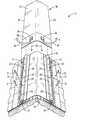
- a ridge vent system 11comprises a ridge vent 12 attached to a shingled roof 13 extending along a ridge 14 of the roof.
- a ridge slot 51( FIG. 3 ) is formed along the ridge 14 and is covered by the ridge vent 12 as is known in the art.
- the ridge vent 12which may be made of injection molded plastic, has an elongated laterally flexible panel 16 with a central portion and edge portions.
- a surface 17 of the ridge ventfaces upwardly away from the roof 13 .
- ventilation grids 19extend along and beneath the edge portions 18 of the panel 16 and, in the illustrated embodiment, which is not limiting, wind baffles 21 extend along and outboard of the ventilation grids 19 .
- FIG. 3shows only one edge portion of the ridge vent, but it will be understood that the opposite edge portion is a mirror image of the edge portion shown in FIG. 3 .
- a first channel member 22extends along one of the edge portions of the panel 16 and a second channel member 23 extends along the opposite edge portion.
- Each channel portionincludes a base 24 that rests against the panel 16 and a hood 26 that extends over the base 24 to form an elongated channel 27 extending along each edge portion of the ridge vent.
- Each channel 27has a channel slot that faces inwardly toward the center of the panel and that provides access to the channel.
- the channel membersare made of extruded plastic or other resilient material so that the channel slots are widened upon insertion of the edge of an auxiliary component into the channels through the channel slots. In this way, the upper edges of the channel slots can bear on the edges of an auxiliary component to help hold it in place.
- the wires 41 and 42 of the solar panel 36can be routed laterally as shown and through the channels 27 so that they are hidden from view and exposure. Electrical connections between multiple end-to-end solar panels may be obtained at the junction boxes 39 and the wires of the last in a series and/or intermediate ones of end-to-end solar panels can be routed to a remote location to deliver electrical power generated by the solar panels. It is thus seen that a solar panel of arbitrary length may be obtained on the ridge vent by attaching a number of independent solar panels together end-to-end and mounting them to the ridge vent as described.
- One suitable flexible solar panel for use in the present inventionis available from PowerFilm® Inc. of Aims, Iowa although other suppliers of such panels are also available.
- the inventionis not limited to flexible solar panels, which tend to be less efficient than traditional more rigid crystalline solar panels.
- Crystalline solar panelsmay be substituted by, for instance, forming a hinged junction between two narrow crystalline solar panels and installing them essentially as described above. A sharper peak will be formed along the ridge of a roof, but this generally is not considered objectionable, and the crystalline solar panels are more efficient at producing electrical power from sunlight.
- FIG. 2shows one possible configuration of a channel member 22 , 23 usable in the present invention.
- the channel member 22 , 23includes a base 24 sized to fit flush on the upper surface of a ridge vent.
- the channel member 22 , 23is bent up along its outer edge and then over the base 24 to form a hood that, along with the base, defines a channel 27 that extends along the channel member.
- the inside edge of the hood 26may be bent down as shown to form with the base a channel slot opening into the channel 27 .
- Spaced nail holes 28are punched or otherwise formed in the hood 26 to accommodate nails as described above.
- the channel membersmay be formed of plastic that is resistant to UV radiation and the elements and preferably is formed by extrusion through a die.
- An array of nail bosses 29project downwardly from the panel 16 to rest on the roof and the nail bosses have internal passageways through which nails 31 are inserted and driven into the roof deck below to secure the ridge vent to the roof.
- the ridge ventalso may have additional depending supports and/or rain baffles that are omitted from FIG. 3 for clarity.
- a channel member 22is mounted to and extends along the edge portion 18 of the panel 16 as described.
- the channel member 22has a base 24 and a hood 26 that overlies the base to define a channel extending along the channel member.
- the inner edge of the hood 26is bent down and in to define a channel slot opening into the channel of the channel member.
- FIG. 3shows clearly how the heads 30 of the nails 31 bear against the base 24 of the channel member 22 to fix and hold the channel member securely to the panel 16 .
- the flexible solar panel 26is shown clearly in FIG. 3 with its edges 35 extending through the channel slot and disposed within the channel 27 of the channel member 22 .
- the channel memberis made of a somewhat resilient material so that the upper edge of the channel slot bears on the flexible solar panel 36 to help hold it in place.
- the ventilation function of the ridge ventis not impaired as air flows freely out of the attic as indicated at 52 and vents to the atmosphere as indicated at 53 .
- the ridge vent system of the inventionserves the function of ventilation and also serves an auxiliary function such as the production of electrical power.
- FIG. 4depicts an end of a ridge vent system according to the invention with a flexible solar panel 36 mounted on a ridge vent and held in place along its edges by channel members 22 and 23 .
- the flexible solar panel 36has an active portion 37 that produces electrical power when exposed to sunlight and an inactive endlap portion 38 .
- Junction boxes 39are disposed on the endlap portion 37 and are connected to the positive and negative electrical outputs of the active portion 37 of the solar panel 36 .
- a positive wire 41(or vice versa) extends from one of the junction boxes and a negative wire 42 (or vice versa) extends from the other one of the junction boxes. The management of these wires so that they are not seen and are better protected is accomplished by extending the wires through the channels 27 of the channel members as shown.
- the endlap portions of solar panels that are arranged end-to-end along the ridge ventare covered by the end of the active portion of the next adjacent solar panel.
- the end of the last solar panel in the array, such as that illustrated in FIG. 4may be covered by a membrane to protect and hide the junction boxes and wires.
- FIG. 4illustrates a suitable end plug for this purpose.
- the end plug 56preferably is made of a semi-rigid foam material and has a profile 57 that matches that of the interior of the channels formed by the channel members.
- a slot 58is formed along the end plug 56 for receiving the in-turned end of the hood at the channel slot of the channel.
- FIGS. 6 and 7illustrate one possible embodiment of an electrical box that houses electronic components that transform the DC electrical power of the solar panels to usable AC power that can be accessed by homeowners, particularly in an emergency power outage.
- the electrical boxmay be mounted in an attic, garage, outbuilding, or other location and wires from the solar panels of the ridge vent system connect to the electrical box.
- the electrical box 66includes an enclosure 67 that houses one or more rechargeable batteries 68 , a charge controller 69 , and a power inverter 71 .
- the DC output of the solar panelsis connected through the charge controller to the DC inputs of the power inverter 71 .
- the charge controllermanages the charging of the batteries and insures that they are not overcharged or produce undesirable back-currents as they charge.
- the power inverter 71converts the DC electrical power from the solar panels, or the DC electrical power stored in the batteries, to AC electrical power.
- An AC cable extending through conduit 72connects to the AC output of the power inverter 71 and extends out of the enclosure 67 , where it terminates at a traditional AC outlet 72 .
- AC poweris thus accessible when the solar panels are exposed to sunlight through the AC outlet 72 .
- the system of this inventionmost preferably is not coupled to the public electrical grid as are traditional home solar power systems. Thus, independent AC power is accessible at the AC outlet 72 regardless of whether the public electrical power grid is up or down.
- the AC electrical powerderives from the DC power generated by the solar panels.
- the AC electrical powerderives from DC power previously stored in the batteries 68 .
- the solar panels of the present ridge vent systemare insufficiently numerous to produce large amounts of electrical power. Thus, it is not intended that large appliances or other power thirsty equipment be operated with the system disclosed herein. Rather, it is intended to provide a source of emergency electrical power when the public electrical grid is down for extended periods of time.
- the electrical powercan be used to maintain the charge of cell phones, flashlights, and radios and may be used to operate televisions to provide emergency information to homeowners.
- the system of this inventionmay be installed on a tool shed and connected to maintain the charge of battery powered tools even when the public electrical grid is down. These and other uses are particularly helpful during large and extended emergencies such as hurricanes and debilitating blizzards.
- FIG. 8is an electrical schematic showing one possible arrangement of electronic components for use in the invention.
- the solar ridge vent system 36previously described, is connected through a fuse F to the inputs of a charge controller 77 , which controls the charging of one or more batteries of a battery bank 82 .
- the positive output of the charge controller 77is connected to the positive terminal of the battery bank 82 and, through circuit breaker 83 , to the positive DC input of the power inverter 89 .
- the negative output of the charge controller 77is connected to the negative input of the power inverter 89 and, through shunt 84 , to the negative terminal of the battery bank 82 .
- the shuntis controllable by a meter 87 , which can, if necessary, discontinue the flow of DC power from the solar panels to the battery bank.
- a meter 87which can, if necessary, discontinue the flow of DC power from the solar panels to the battery bank.
- DC electrical power from the solar panels of system 36 and DC power from the battery bank 82are coupled to the DC input of the power inverter 89 .
- the power inverter 89converts the DC input to AC electrical power that can be accessed through hot, neutral, and ground leads on the AC output of the power inverter. These leads, in turn, are connected to an AC circuit breaker panel and then to a user accessible AC outlet 73 ( FIG. 7 ).
- the AC circuit breaker panelincludes circuit breakers to ensure that large demands for AC power exceeding the limits of the system do not destroy components of the system. As mentioned, the system of this invention is not intended to supply large amounts of power for powering larger appliances.
- An auxiliary AC generatormay be connected to the AC inputs of the power inverter if desired to provide AC power at the AC outlet 73 if the solar panels should fail or the battery bank be drained. While one particular arrangement of components and their connections are illustrated as exemplary, it will be understood that a variety of other or different components may be used to accomplish the functions of the invention in equivalent ways.
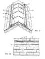
- FIGS. 9 and 10show the ridge vent system of the present invention used for purposes other than electrical power generation.
- slate caps 91 of the type used to cap slate roofsare mounted on the ridge vent and held in place with their edges extending into the channels formed by channel members 22 and 23 . No nails or auxiliary fasteners are required.
- FIG. 10shows a similar use wherein traditional asphalt ridge cap shingles 92 are mounted on the ridge vent and held in place with their edges extending into the channels of the channel members.
- Other applications not shownalso are possible.
- an emergency panel containing light emitting elementsmay be mounted on the ridge vent and connected to a security system to be lighted or flashed when there is a break-in or other emergency.
- the system of the inventionalso may be used to heat water by mounting on the ridge vent a bat of material through which fluid conduits extend. When the ridge vent is exposed to sunlight, fluid moving through the conduits absorbs the solar heat and the hot fluid may be used in a heat exchanger to heat water or for other purposes.
- the materials suggested for the various componentsare not limiting and may be substituted with others with equivalent results.
- the ridge ventmay itself be molded with the channel members as a unitary feature of the ridge vent.
- semi-rigid injection molded ridge ventsare illustrated in the exemplary embodiments, it is contemplated and within the scope of the invention that other types of ridge vents, such as those made of open weave material, may be formed or provided with channels for attaching components within the scope of the invention. Accordingly, the scope of the invention exemplified in the above description is delimited only by the claims.
Landscapes
- Engineering & Computer Science (AREA)
- Architecture (AREA)
- Civil Engineering (AREA)
- Structural Engineering (AREA)
- Roof Covering Using Slabs Or Stiff Sheets (AREA)
- Photovoltaic Devices (AREA)
Abstract
Description
Claims (5)
Priority Applications (3)
| Application Number | Priority Date | Filing Date | Title |
|---|---|---|---|
| US13/799,677US8925262B2 (en) | 2013-03-13 | 2013-03-13 | Multi-purpose ridge vent system |
| CA2845889ACA2845889C (en) | 2013-03-13 | 2014-03-12 | Multi-purpose ridge vent system |
| MX2014003029AMX342447B (en) | 2013-03-13 | 2014-03-13 | MULTI PURPLE VENTILATION SYSTEM. |
Applications Claiming Priority (1)
| Application Number | Priority Date | Filing Date | Title |
|---|---|---|---|
| US13/799,677US8925262B2 (en) | 2013-03-13 | 2013-03-13 | Multi-purpose ridge vent system |
Publications (2)
| Publication Number | Publication Date |
|---|---|
| US20140259998A1 US20140259998A1 (en) | 2014-09-18 |
| US8925262B2true US8925262B2 (en) | 2015-01-06 |
Family
ID=51520900
Family Applications (1)
| Application Number | Title | Priority Date | Filing Date |
|---|---|---|---|
| US13/799,677ActiveUS8925262B2 (en) | 2013-03-13 | 2013-03-13 | Multi-purpose ridge vent system |
Country Status (3)
| Country | Link |
|---|---|
| US (1) | US8925262B2 (en) |
| CA (1) | CA2845889C (en) |
| MX (1) | MX342447B (en) |
Cited By (60)
| Publication number | Priority date | Publication date | Assignee | Title |
|---|---|---|---|---|
| US9695594B2 (en)* | 2015-06-16 | 2017-07-04 | Liberty Diversified International, Inc. | Ridge vent |
| US10281189B2 (en) | 2016-03-04 | 2019-05-07 | Kason Industries, Inc. | Cold room combination vent and light |
| US10739055B2 (en) | 2018-06-29 | 2020-08-11 | Kason Industries, Inc. | Cold room combination vent and light |
| US10845115B2 (en) | 2018-06-29 | 2020-11-24 | Kason Industries, Inc. | Cold room combination vent and light |
| US11177639B1 (en) | 2020-05-13 | 2021-11-16 | GAF Energy LLC | Electrical cable passthrough for photovoltaic systems |
| US11217715B2 (en) | 2020-04-30 | 2022-01-04 | GAF Energy LLC | Photovoltaic module frontsheet and backsheet |
| US11251744B1 (en) | 2020-06-04 | 2022-02-15 | GAF Energy LLC | Photovoltaic shingles and methods of installing same |
| US20220060141A1 (en)* | 2020-08-24 | 2022-02-24 | Colin Felton | Labor Saving Solar Roofing Shingle |
| US11283394B2 (en) | 2020-02-18 | 2022-03-22 | GAF Energy LLC | Photovoltaic module with textured superstrate providing shingle-mimicking appearance |
| US11309828B2 (en) | 2019-11-27 | 2022-04-19 | GAF Energy LLC | Roof integrated photovoltaic module with spacer |
| USD950482S1 (en) | 2020-10-02 | 2022-05-03 | GAF Energy LLC | Solar roofing system |
| USD950481S1 (en) | 2020-10-02 | 2022-05-03 | GAF Energy LLC | Solar roofing system |
| US11394344B2 (en) | 2020-08-11 | 2022-07-19 | GAF Energy LLC | Roof mounted photovoltaic system and method for wireless transfer of electrical energy |
| US11398795B2 (en) | 2019-12-20 | 2022-07-26 | GAF Energy LLC | Roof integrated photovoltaic system |
| US11431281B2 (en) | 2020-02-27 | 2022-08-30 | GAF Energy LLC | Photovoltaic module with light-scattering encapsulant providing shingle-mimicking appearance |
| US11444569B2 (en) | 2020-10-14 | 2022-09-13 | GAF Energy LLC | Mounting apparatus for photovoltaic modules |
| US11454027B2 (en) | 2020-10-29 | 2022-09-27 | GAF Energy LLC | System of roofing and photovoltaic shingles and methods of installing same |
| US11459757B2 (en) | 2021-01-19 | 2022-10-04 | GAF Energy LLC | Watershedding features for roofing shingles |
| US11489482B2 (en) | 2020-01-22 | 2022-11-01 | GAF Energy LLC | Integrated photovoltaic roofing shingles, methods, systems, and kits thereof |
| US11486144B2 (en) | 2020-11-12 | 2022-11-01 | GAF Energy LLC | Roofing shingles with handles |
| US11496088B2 (en) | 2021-02-19 | 2022-11-08 | GAF Energy LLC | Photovoltaic module for a roof with continuous fiber tape |
| US11508861B1 (en) | 2021-06-02 | 2022-11-22 | GAF Energy LLC | Photovoltaic module with light-scattering encapsulant providing shingle-mimicking appearance |
| US11512480B1 (en) | 2021-07-16 | 2022-11-29 | GAF Energy LLC | Roof material storage bracket |
| US11527665B2 (en) | 2021-05-06 | 2022-12-13 | GAF Energy LLC | Photovoltaic module with transparent perimeter edges |
| US11545928B2 (en) | 2020-10-13 | 2023-01-03 | GAF Energy LLC | Solar roofing system |
| US11545927B2 (en) | 2020-04-09 | 2023-01-03 | GAF Energy LLC | Three-dimensional laminate photovoltaic module |
| US11728759B2 (en) | 2021-09-01 | 2023-08-15 | GAF Energy LLC | Photovoltaic modules for commercial roofing |
| US11811361B1 (en) | 2022-12-14 | 2023-11-07 | GAF Energy LLC | Rapid shutdown device for photovoltaic modules |
| US11824487B2 (en) | 2020-11-13 | 2023-11-21 | GAF Energy LLC | Photovoltaic module systems and methods |
| US11824486B2 (en) | 2022-01-20 | 2023-11-21 | GAF Energy LLC | Roofing shingles for mimicking the appearance of photovoltaic modules |
| US11843067B2 (en) | 2020-07-22 | 2023-12-12 | GAF Energy LLC | Photovoltaic modules |
| US11855431B2 (en)* | 2022-03-30 | 2023-12-26 | Bmic Llc | Modular electronics roofing attachment and methods of use thereof |
| US11870227B2 (en) | 2020-09-03 | 2024-01-09 | GAF Energy LLC | Building integrated photovoltaic system |
| US11961928B2 (en) | 2020-02-27 | 2024-04-16 | GAF Energy LLC | Photovoltaic module with light-scattering encapsulant providing shingle-mimicking appearance |
| US11984521B2 (en) | 2022-03-10 | 2024-05-14 | GAF Energy LLC | Combined encapsulant and backsheet for photovoltaic modules |
| US11996797B2 (en) | 2020-12-02 | 2024-05-28 | GAF Energy LLC | Step flaps for photovoltaic and roofing shingles |
| US12009782B1 (en) | 2023-04-04 | 2024-06-11 | GAF Energy LLC | Photovoltaic systems with wireways |
| US12009781B2 (en) | 2021-07-06 | 2024-06-11 | GAF Energy LLC | Jumper module for photovoltaic systems |
| US12015374B2 (en) | 2022-09-26 | 2024-06-18 | GAF Energy LLC | Photovoltaic modules integrated with building siding and fencing |
| US12013153B2 (en) | 2022-02-08 | 2024-06-18 | GAF Energy LLC | Building integrated photovoltaic system |
| US12031332B2 (en) | 2022-10-25 | 2024-07-09 | GAF Energy LLC | Roofing materials and related methods |
| US12034089B2 (en) | 2022-09-01 | 2024-07-09 | GAF Energy LLC | Anti-reflective photovoltaic shingles and related methods |
| US12051996B2 (en) | 2022-09-13 | 2024-07-30 | GAF Energy LLC | Sensing roofing system and method thereof |
| US12095415B2 (en) | 2021-03-29 | 2024-09-17 | GAF Energy LLC | Electrical components for photovoltaic systems |
| US12143064B2 (en) | 2022-09-29 | 2024-11-12 | GAF Energy LLC | Jumper module with sleeve |
| US12145348B2 (en) | 2022-08-24 | 2024-11-19 | GAF Energy LLC | System for forming a roofing membrane, and associated method |
| US12176849B2 (en) | 2023-02-23 | 2024-12-24 | GAF Energy LLC | Photovoltaic shingles with multi-module power electronics |
| US12199550B2 (en) | 2022-04-08 | 2025-01-14 | GAF Energy LLC | Low profile connector for solar roofing systems |
| US12209414B2 (en) | 2022-02-23 | 2025-01-28 | GAF Energy LLC | Roofing shingle and method of manufacturing same |
| US12231075B2 (en) | 2022-10-27 | 2025-02-18 | GAF Energy LLC | Building integrated photovoltaic systems |
| US12237809B2 (en) | 2022-06-06 | 2025-02-25 | GAF Energy LLC | Active component indicators for photovoltaic systems |
| US12316268B2 (en) | 2023-10-26 | 2025-05-27 | GAF Energy LLC | Roofing systems with water ingress protection |
| US12325996B2 (en) | 2022-07-15 | 2025-06-10 | GAF Energy LLC | Solar roofing system with fiber composite roofing shingles |
| US12355390B1 (en) | 2023-02-03 | 2025-07-08 | GAF Energy LLC | Solar shingle and associated roofing system and method |
| US12414385B2 (en) | 2022-08-29 | 2025-09-09 | GAF Energy LLC | Photovoltaic modules with offset layers |
| US12413177B2 (en) | 2023-08-31 | 2025-09-09 | GAF Energy LLC | Photovoltaic modules and roofing shingles with nail zones |
| US12413183B2 (en) | 2022-11-15 | 2025-09-09 | GAF Energy LLC | Electrical cable passthrough for photovoltaic systems |
| US12413174B2 (en) | 2023-02-21 | 2025-09-09 | GAF Energy LLC | Roofing system including photovoltaic module wireway cover, and associated method |
| US12438495B2 (en) | 2023-12-05 | 2025-10-07 | GAF Energy LLC | Roofing system for prevention of roofing shingle deformation |
| US12445089B2 (en) | 2024-02-02 | 2025-10-14 | GAF Energy LLC | Photovoltaic module, and associated kit, system, and method |
Families Citing this family (18)
| Publication number | Priority date | Publication date | Assignee | Title |
|---|---|---|---|---|
| WO2013081477A1 (en) | 2011-11-30 | 2013-06-06 | Zinniatek Limited | A roofing, cladding or siding product, its manufacture and its use as part of a solar energy recovery system |
| JP6541351B2 (en) | 2011-11-30 | 2019-07-10 | ジニアテック リミテッド | Photovoltaic system |
| WO2014074956A1 (en)* | 2012-11-08 | 2014-05-15 | Cameron D | Modular structural system for solar panel installation |
| US9954480B2 (en) | 2013-05-23 | 2018-04-24 | Zinnatek Limited | Photovoltaic systems |
| CA2939891C (en) | 2014-03-07 | 2021-03-23 | Zinniatek Limited | Solar thermal roofing system |
| JP6334357B2 (en)* | 2014-10-06 | 2018-05-30 | 株式会社ノーリツ | Installation structure of solar energy utilization equipment |
| EP3227506B1 (en) | 2014-12-01 | 2023-06-14 | Zinniatek Limited | A roofing, cladding or siding product |
| AU2015356689B2 (en) | 2014-12-01 | 2020-10-15 | Zinniatek Limited | A roofing, cladding or siding apparatus |
| US10787814B2 (en)* | 2016-07-28 | 2020-09-29 | Building Materials Investment Corporation | Multi-layered cap shingle with enhanced wind performance and method of making same |
| JP7005002B2 (en)* | 2016-09-21 | 2022-01-21 | 株式会社トーコー | Construction method of cable lead-in unit such as solar cell and cable lead-in unit such as solar cell |
| US10879842B2 (en) | 2016-10-17 | 2020-12-29 | Zinniatek Limited | Roofing, cladding or siding module or apparatus |
| JP2020510148A (en) | 2017-02-21 | 2020-04-02 | ジニアテック リミテッド | Base material having decorative surface and manufacturing method |
| AU2018302522A1 (en)* | 2017-07-20 | 2020-02-13 | Zinniatek Limited | A roof, siding, or cladding, or ridge or hip member for a roof |
| US11702840B2 (en) | 2018-12-19 | 2023-07-18 | Zinniatek Limited | Roofing, cladding or siding module, its manufacture and use |
| JP7194989B2 (en)* | 2019-01-08 | 2022-12-23 | 株式会社トーコー | Cable lead-in unit for solar cells, etc. |
| US20200340695A1 (en)* | 2019-07-10 | 2020-10-29 | Leon E. Munson, III | Powered roof ridge ventilation system |
| CN114901556A (en)* | 2019-11-15 | 2022-08-12 | Bmic有限责任公司 | Integrated roof accessories for unmanned vehicle navigation and methods and systems incorporating same |
| CN111305444B (en)* | 2020-03-04 | 2021-09-21 | 吉林省东源水利水电工程咨询有限公司 | Solar panel room for ice and snow area |
Citations (9)
| Publication number | Priority date | Publication date | Assignee | Title |
|---|---|---|---|---|
| US3325951A (en)* | 1964-07-13 | 1967-06-20 | Reginald Perry C | Adjustable skylight |
| US4139399A (en)* | 1978-01-18 | 1979-02-13 | Solarex Corporation | Solar panel with removable cell matrix, and method of making same |
| US4571897A (en)* | 1983-07-21 | 1986-02-25 | Fred Kerr | Apparatus for mounting sheet material and mounting assembly and structural surface formed therewith |
| US4643080A (en)* | 1985-06-24 | 1987-02-17 | Aluminum Company Of America | Roof ridge ventilator system |
| JPH0960227A (en)* | 1995-08-24 | 1997-03-04 | Misawa Homes Co Ltd | Installing structure for solar cell panel on building roof |
| US5803806A (en)* | 1997-10-23 | 1998-09-08 | Blessinger; James | Apparatus and method for insulating roofridge ventilator systems |
| US6283852B1 (en)* | 2000-08-11 | 2001-09-04 | Klauer Manufacturing Company | Roofline ventilator assembly |
| US7219473B2 (en)* | 2005-03-07 | 2007-05-22 | Canplas Industries Ltd. | Ridge vent apparatus |
| US20130074428A1 (en)* | 2011-09-22 | 2013-03-28 | Digital Control Systems, Inc. | Roof ridge ventilation system |
- 2013
- 2013-03-13USUS13/799,677patent/US8925262B2/enactiveActive
- 2014
- 2014-03-12CACA2845889Apatent/CA2845889C/enactiveActive
- 2014-03-13MXMX2014003029Apatent/MX342447B/enactiveIP Right Grant
Patent Citations (9)
| Publication number | Priority date | Publication date | Assignee | Title |
|---|---|---|---|---|
| US3325951A (en)* | 1964-07-13 | 1967-06-20 | Reginald Perry C | Adjustable skylight |
| US4139399A (en)* | 1978-01-18 | 1979-02-13 | Solarex Corporation | Solar panel with removable cell matrix, and method of making same |
| US4571897A (en)* | 1983-07-21 | 1986-02-25 | Fred Kerr | Apparatus for mounting sheet material and mounting assembly and structural surface formed therewith |
| US4643080A (en)* | 1985-06-24 | 1987-02-17 | Aluminum Company Of America | Roof ridge ventilator system |
| JPH0960227A (en)* | 1995-08-24 | 1997-03-04 | Misawa Homes Co Ltd | Installing structure for solar cell panel on building roof |
| US5803806A (en)* | 1997-10-23 | 1998-09-08 | Blessinger; James | Apparatus and method for insulating roofridge ventilator systems |
| US6283852B1 (en)* | 2000-08-11 | 2001-09-04 | Klauer Manufacturing Company | Roofline ventilator assembly |
| US7219473B2 (en)* | 2005-03-07 | 2007-05-22 | Canplas Industries Ltd. | Ridge vent apparatus |
| US20130074428A1 (en)* | 2011-09-22 | 2013-03-28 | Digital Control Systems, Inc. | Roof ridge ventilation system |
Cited By (87)
| Publication number | Priority date | Publication date | Assignee | Title |
|---|---|---|---|---|
| US9695594B2 (en)* | 2015-06-16 | 2017-07-04 | Liberty Diversified International, Inc. | Ridge vent |
| US10281189B2 (en) | 2016-03-04 | 2019-05-07 | Kason Industries, Inc. | Cold room combination vent and light |
| US10739055B2 (en) | 2018-06-29 | 2020-08-11 | Kason Industries, Inc. | Cold room combination vent and light |
| US10845115B2 (en) | 2018-06-29 | 2020-11-24 | Kason Industries, Inc. | Cold room combination vent and light |
| US11309828B2 (en) | 2019-11-27 | 2022-04-19 | GAF Energy LLC | Roof integrated photovoltaic module with spacer |
| US12191796B2 (en) | 2019-12-20 | 2025-01-07 | GAF Energy LLC | Roof integrated photovoltaic system |
| US11398795B2 (en) | 2019-12-20 | 2022-07-26 | GAF Energy LLC | Roof integrated photovoltaic system |
| US12051990B2 (en) | 2020-01-22 | 2024-07-30 | GAF Energy LLC | Integrated photovoltaic roofing shingles, methods, systems, and kits thereof |
| US12413176B2 (en) | 2020-01-22 | 2025-09-09 | GAF Energy LLC | Integrated photovoltaic roofing shingles, methods, systems, and kits thereof |
| US11489482B2 (en) | 2020-01-22 | 2022-11-01 | GAF Energy LLC | Integrated photovoltaic roofing shingles, methods, systems, and kits thereof |
| US11283394B2 (en) | 2020-02-18 | 2022-03-22 | GAF Energy LLC | Photovoltaic module with textured superstrate providing shingle-mimicking appearance |
| US11961928B2 (en) | 2020-02-27 | 2024-04-16 | GAF Energy LLC | Photovoltaic module with light-scattering encapsulant providing shingle-mimicking appearance |
| US11431281B2 (en) | 2020-02-27 | 2022-08-30 | GAF Energy LLC | Photovoltaic module with light-scattering encapsulant providing shingle-mimicking appearance |
| US11545927B2 (en) | 2020-04-09 | 2023-01-03 | GAF Energy LLC | Three-dimensional laminate photovoltaic module |
| US11424379B2 (en) | 2020-04-30 | 2022-08-23 | GAF Energy LLC | Photovoltaic module frontsheet and backsheet |
| US11705531B2 (en) | 2020-04-30 | 2023-07-18 | GAF Energy LLC | Photovoltaic module frontsheet and backsheet |
| US11217715B2 (en) | 2020-04-30 | 2022-01-04 | GAF Energy LLC | Photovoltaic module frontsheet and backsheet |
| US11177639B1 (en) | 2020-05-13 | 2021-11-16 | GAF Energy LLC | Electrical cable passthrough for photovoltaic systems |
| US11658470B2 (en) | 2020-05-13 | 2023-05-23 | GAF Energy LLC | Electrical cable passthrough |
| US11251744B1 (en) | 2020-06-04 | 2022-02-15 | GAF Energy LLC | Photovoltaic shingles and methods of installing same |
| US11876480B2 (en) | 2020-06-04 | 2024-01-16 | GAF Energy LLC | Photovoltaic shingles and methods of installing same |
| US11404997B2 (en) | 2020-06-04 | 2022-08-02 | GAF Energy LLC | Photovoltaic shingles and methods of installing same |
| US11843067B2 (en) | 2020-07-22 | 2023-12-12 | GAF Energy LLC | Photovoltaic modules |
| US11394344B2 (en) | 2020-08-11 | 2022-07-19 | GAF Energy LLC | Roof mounted photovoltaic system and method for wireless transfer of electrical energy |
| US12126301B2 (en) | 2020-08-11 | 2024-10-22 | GAF Energy LLC | Roof mounted photovoltaic system and method for wireless transfer of electrical energy |
| US20220060141A1 (en)* | 2020-08-24 | 2022-02-24 | Colin Felton | Labor Saving Solar Roofing Shingle |
| US12395116B2 (en)* | 2020-08-24 | 2025-08-19 | Colin Felton | Labor saving solar roofing shingle |
| US11870227B2 (en) | 2020-09-03 | 2024-01-09 | GAF Energy LLC | Building integrated photovoltaic system |
| USD950482S1 (en) | 2020-10-02 | 2022-05-03 | GAF Energy LLC | Solar roofing system |
| USD950481S1 (en) | 2020-10-02 | 2022-05-03 | GAF Energy LLC | Solar roofing system |
| US11545928B2 (en) | 2020-10-13 | 2023-01-03 | GAF Energy LLC | Solar roofing system |
| US12413175B2 (en) | 2020-10-13 | 2025-09-09 | GAF Energy LLC | Solar roofing system |
| US12255575B2 (en) | 2020-10-14 | 2025-03-18 | GAF Energy LLC | Mounting apparatus for photovoltaic modules |
| US11689149B2 (en) | 2020-10-14 | 2023-06-27 | GAF Energy LLC | Mounting apparatus for photovoltaic modules |
| US11444569B2 (en) | 2020-10-14 | 2022-09-13 | GAF Energy LLC | Mounting apparatus for photovoltaic modules |
| US12123194B2 (en) | 2020-10-29 | 2024-10-22 | GAF Energy LLC | System of roofing and photovoltaic shingles and methods of installing same |
| US11454027B2 (en) | 2020-10-29 | 2022-09-27 | GAF Energy LLC | System of roofing and photovoltaic shingles and methods of installing same |
| US11486144B2 (en) | 2020-11-12 | 2022-11-01 | GAF Energy LLC | Roofing shingles with handles |
| US11661745B2 (en) | 2020-11-12 | 2023-05-30 | GAF Energy LLC | Roofing shingles with handles |
| US11824487B2 (en) | 2020-11-13 | 2023-11-21 | GAF Energy LLC | Photovoltaic module systems and methods |
| US11996797B2 (en) | 2020-12-02 | 2024-05-28 | GAF Energy LLC | Step flaps for photovoltaic and roofing shingles |
| US11459757B2 (en) | 2021-01-19 | 2022-10-04 | GAF Energy LLC | Watershedding features for roofing shingles |
| US11965335B2 (en) | 2021-01-19 | 2024-04-23 | GAF Energy LLC | Watershedding features for roofing shingles |
| US11496088B2 (en) | 2021-02-19 | 2022-11-08 | GAF Energy LLC | Photovoltaic module for a roof with continuous fiber tape |
| US12191797B2 (en) | 2021-02-19 | 2025-01-07 | GAF Energy LLC | Photovoltaic module for a roof with continuous fiber tape |
| US12095415B2 (en) | 2021-03-29 | 2024-09-17 | GAF Energy LLC | Electrical components for photovoltaic systems |
| US11527665B2 (en) | 2021-05-06 | 2022-12-13 | GAF Energy LLC | Photovoltaic module with transparent perimeter edges |
| US11869997B2 (en) | 2021-05-06 | 2024-01-09 | GAF Energy LLC | Photovoltaic module with transparent perimeter edges |
| US11508861B1 (en) | 2021-06-02 | 2022-11-22 | GAF Energy LLC | Photovoltaic module with light-scattering encapsulant providing shingle-mimicking appearance |
| US12100775B2 (en) | 2021-06-02 | 2024-09-24 | GAF Energy LLC | Photovoltaic module with light-scattering encapsulant providing shingle-mimicking appearance |
| US12009781B2 (en) | 2021-07-06 | 2024-06-11 | GAF Energy LLC | Jumper module for photovoltaic systems |
| US11512480B1 (en) | 2021-07-16 | 2022-11-29 | GAF Energy LLC | Roof material storage bracket |
| US11732490B2 (en) | 2021-07-16 | 2023-08-22 | GAF Energy LLC | Roof material storage bracket |
| US12009773B2 (en) | 2021-09-01 | 2024-06-11 | GAF Energy LLC | Photovoltaic modules for commercial roofing |
| US11728759B2 (en) | 2021-09-01 | 2023-08-15 | GAF Energy LLC | Photovoltaic modules for commercial roofing |
| US12278591B2 (en) | 2022-01-20 | 2025-04-15 | GAF Energy LLC | Roofing shingles for mimicking the appearance of photovoltaic modules |
| US11824486B2 (en) | 2022-01-20 | 2023-11-21 | GAF Energy LLC | Roofing shingles for mimicking the appearance of photovoltaic modules |
| US12013153B2 (en) | 2022-02-08 | 2024-06-18 | GAF Energy LLC | Building integrated photovoltaic system |
| US12209414B2 (en) | 2022-02-23 | 2025-01-28 | GAF Energy LLC | Roofing shingle and method of manufacturing same |
| US11984521B2 (en) | 2022-03-10 | 2024-05-14 | GAF Energy LLC | Combined encapsulant and backsheet for photovoltaic modules |
| US11855431B2 (en)* | 2022-03-30 | 2023-12-26 | Bmic Llc | Modular electronics roofing attachment and methods of use thereof |
| US12199550B2 (en) | 2022-04-08 | 2025-01-14 | GAF Energy LLC | Low profile connector for solar roofing systems |
| US12237809B2 (en) | 2022-06-06 | 2025-02-25 | GAF Energy LLC | Active component indicators for photovoltaic systems |
| US12325996B2 (en) | 2022-07-15 | 2025-06-10 | GAF Energy LLC | Solar roofing system with fiber composite roofing shingles |
| US12145348B2 (en) | 2022-08-24 | 2024-11-19 | GAF Energy LLC | System for forming a roofing membrane, and associated method |
| US12414385B2 (en) | 2022-08-29 | 2025-09-09 | GAF Energy LLC | Photovoltaic modules with offset layers |
| US12034089B2 (en) | 2022-09-01 | 2024-07-09 | GAF Energy LLC | Anti-reflective photovoltaic shingles and related methods |
| US12051996B2 (en) | 2022-09-13 | 2024-07-30 | GAF Energy LLC | Sensing roofing system and method thereof |
| US12015374B2 (en) | 2022-09-26 | 2024-06-18 | GAF Energy LLC | Photovoltaic modules integrated with building siding and fencing |
| US12143064B2 (en) | 2022-09-29 | 2024-11-12 | GAF Energy LLC | Jumper module with sleeve |
| US12031332B2 (en) | 2022-10-25 | 2024-07-09 | GAF Energy LLC | Roofing materials and related methods |
| US12231075B2 (en) | 2022-10-27 | 2025-02-18 | GAF Energy LLC | Building integrated photovoltaic systems |
| US12413183B2 (en) | 2022-11-15 | 2025-09-09 | GAF Energy LLC | Electrical cable passthrough for photovoltaic systems |
| US11811361B1 (en) | 2022-12-14 | 2023-11-07 | GAF Energy LLC | Rapid shutdown device for photovoltaic modules |
| US12255581B2 (en) | 2022-12-14 | 2025-03-18 | GAF Energy LLC | Rapid shutdown device for photovoltaic modules |
| US12255580B2 (en) | 2022-12-14 | 2025-03-18 | GAF Energy LLC | Rapid shutdown device for photovoltaic modules |
| US12355390B1 (en) | 2023-02-03 | 2025-07-08 | GAF Energy LLC | Solar shingle and associated roofing system and method |
| US12413174B2 (en) | 2023-02-21 | 2025-09-09 | GAF Energy LLC | Roofing system including photovoltaic module wireway cover, and associated method |
| US12407296B2 (en) | 2023-02-23 | 2025-09-02 | GAF Energy LLC | Photovoltaic shingles with multi-module power electronics |
| US12176849B2 (en) | 2023-02-23 | 2024-12-24 | GAF Energy LLC | Photovoltaic shingles with multi-module power electronics |
| US12424973B2 (en) | 2023-04-04 | 2025-09-23 | GAF Energy LLC | Photovoltaic systems with wireways |
| US12009782B1 (en) | 2023-04-04 | 2024-06-11 | GAF Energy LLC | Photovoltaic systems with wireways |
| US12446329B2 (en) | 2023-06-01 | 2025-10-14 | GAF Energy LLC | Photovoltaic module frontsheet and backsheet |
| US12413177B2 (en) | 2023-08-31 | 2025-09-09 | GAF Energy LLC | Photovoltaic modules and roofing shingles with nail zones |
| US12316268B2 (en) | 2023-10-26 | 2025-05-27 | GAF Energy LLC | Roofing systems with water ingress protection |
| US12438495B2 (en) | 2023-12-05 | 2025-10-07 | GAF Energy LLC | Roofing system for prevention of roofing shingle deformation |
| US12445089B2 (en) | 2024-02-02 | 2025-10-14 | GAF Energy LLC | Photovoltaic module, and associated kit, system, and method |
Also Published As
| Publication number | Publication date |
|---|---|
| MX342447B (en) | 2016-09-29 |
| CA2845889C (en) | 2020-07-07 |
| US20140259998A1 (en) | 2014-09-18 |
| CA2845889A1 (en) | 2014-09-13 |
| MX2014003029A (en) | 2014-11-05 |
Similar Documents
| Publication | Publication Date | Title |
|---|---|---|
| US8925262B2 (en) | Multi-purpose ridge vent system | |
| US20230283224A1 (en) | Roof integrated solar power system with top mounted electrical components and cables | |
| US8713860B2 (en) | Shingled roof with integrated photovoltaic collectors | |
| US10115850B2 (en) | Roof integrated solar panel system with side mounted micro inverters | |
| EP1935032B1 (en) | Photovoltaic roof ridge cap and installation method | |
| US9166523B2 (en) | Low profile solar roof shingle system with integrated nano-inverters | |
| US10505493B2 (en) | Building integrated photovoltaic tile mounting system | |
| US6606830B2 (en) | Solar cell-bearing roof and method for installing solar cell-bearing roof | |
| US20140090310A1 (en) | Solar Roof Module for metal buildings | |
| US20230246591A1 (en) | Photovoltaic plant | |
| CA2893726C (en) | Modular solar panel roof system | |
| US20160010886A1 (en) | Concealed Housing For A Solar Powered Attic Fan | |
| US8482246B2 (en) | Customized shading devices including photovoltaic properties | |
| WO2010006007A1 (en) | Customized shading device including photovoltaic capabilities | |
| JP5131527B2 (en) | Installation structure and installation method of solar cells on the roof | |
| AU2021202734A1 (en) | Solar Shutters Modular Unit | |
| US9973143B1 (en) | Solar panel roof modules | |
| JP6840366B1 (en) | Photovoltaic panel and photovoltaic power generation equipment using it | |
| JPH11206037A (en) | Solar cell unit and structure using solar cell unit | |
| JP2005036604A (en) | Roof material and roof with solar cell module | |
| JP2008231666A (en) | Roof structure | |
| JP3068018U (en) | Ventilation vent with fan | |
| GB2634120A (en) | A photovoltaic apparatus for and method of charging an electric vehicle (EV) or battery thereof | |
| JPH1171874A (en) | Building material, enclosure, installation method of building material, air circulation device and power generation device |
Legal Events
| Date | Code | Title | Description |
|---|---|---|---|
| AS | Assignment | Owner name:BUILDING MATERIALS INVESTMENT CORPORATION, TEXAS Free format text:ASSIGNMENT OF ASSIGNORS INTEREST;ASSIGNORS:RAILKAR, SUDHIR;ZARATE, WALTER;KIIK, MATTI;SIGNING DATES FROM 20140312 TO 20140314;REEL/FRAME:032749/0488 | |
| STCF | Information on status: patent grant | Free format text:PATENTED CASE | |
| MAFP | Maintenance fee payment | Free format text:PAYMENT OF MAINTENANCE FEE, 4TH YEAR, LARGE ENTITY (ORIGINAL EVENT CODE: M1551) Year of fee payment:4 | |
| AS | Assignment | Owner name:BMIC LLC, TEXAS Free format text:CHANGE OF NAME;ASSIGNOR:BUILDING MATERIALS INVESTMENT CORPORATION;REEL/FRAME:057292/0184 Effective date:20210405 | |
| AS | Assignment | Owner name:DEUTSCHE BANK AG NEW YORK BRANCH, NEW YORK Free format text:SECURITY INTEREST;ASSIGNORS:BMIC LLC;ELKCORP;ELK COMPOSITE BUILDING PRODUCTS, INC.;AND OTHERS;REEL/FRAME:057572/0607 Effective date:20210922 | |
| MAFP | Maintenance fee payment | Free format text:PAYMENT OF MAINTENANCE FEE, 8TH YEAR, LARGE ENTITY (ORIGINAL EVENT CODE: M1552); ENTITY STATUS OF PATENT OWNER: LARGE ENTITY Year of fee payment:8 |