US8925164B2 - Valve assembly with exchangeable valve member and a tool set for exchanging the valve member - Google Patents
Valve assembly with exchangeable valve member and a tool set for exchanging the valve memberDownload PDFInfo
- Publication number
- US8925164B2 US8925164B2US13/063,218US200913063218AUS8925164B2US 8925164 B2US8925164 B2US 8925164B2US 200913063218 AUS200913063218 AUS 200913063218AUS 8925164 B2US8925164 B2US 8925164B2
- Authority
- US
- United States
- Prior art keywords
- valve
- tool
- engagement member
- engagement
- valve member
- Prior art date
- Legal status (The legal status is an assumption and is not a legal conclusion. Google has not performed a legal analysis and makes no representation as to the accuracy of the status listed.)
- Expired - Fee Related, expires
Links
Images


Classifications
- A—HUMAN NECESSITIES
- A61—MEDICAL OR VETERINARY SCIENCE; HYGIENE
- A61F—FILTERS IMPLANTABLE INTO BLOOD VESSELS; PROSTHESES; DEVICES PROVIDING PATENCY TO, OR PREVENTING COLLAPSING OF, TUBULAR STRUCTURES OF THE BODY, e.g. STENTS; ORTHOPAEDIC, NURSING OR CONTRACEPTIVE DEVICES; FOMENTATION; TREATMENT OR PROTECTION OF EYES OR EARS; BANDAGES, DRESSINGS OR ABSORBENT PADS; FIRST-AID KITS
- A61F2/00—Filters implantable into blood vessels; Prostheses, i.e. artificial substitutes or replacements for parts of the body; Appliances for connecting them with the body; Devices providing patency to, or preventing collapsing of, tubular structures of the body, e.g. stents
- A61F2/02—Prostheses implantable into the body
- A61F2/24—Heart valves ; Vascular valves, e.g. venous valves; Heart implants, e.g. passive devices for improving the function of the native valve or the heart muscle; Transmyocardial revascularisation [TMR] devices; Valves implantable in the body
- A61F2/2427—Devices for manipulating or deploying heart valves during implantation
- A—HUMAN NECESSITIES
- A61—MEDICAL OR VETERINARY SCIENCE; HYGIENE
- A61F—FILTERS IMPLANTABLE INTO BLOOD VESSELS; PROSTHESES; DEVICES PROVIDING PATENCY TO, OR PREVENTING COLLAPSING OF, TUBULAR STRUCTURES OF THE BODY, e.g. STENTS; ORTHOPAEDIC, NURSING OR CONTRACEPTIVE DEVICES; FOMENTATION; TREATMENT OR PROTECTION OF EYES OR EARS; BANDAGES, DRESSINGS OR ABSORBENT PADS; FIRST-AID KITS
- A61F2/00—Filters implantable into blood vessels; Prostheses, i.e. artificial substitutes or replacements for parts of the body; Appliances for connecting them with the body; Devices providing patency to, or preventing collapsing of, tubular structures of the body, e.g. stents
- A61F2/02—Prostheses implantable into the body
- A61F2/24—Heart valves ; Vascular valves, e.g. venous valves; Heart implants, e.g. passive devices for improving the function of the native valve or the heart muscle; Transmyocardial revascularisation [TMR] devices; Valves implantable in the body
- A61F2/2409—Support rings therefor, e.g. for connecting valves to tissue
- A—HUMAN NECESSITIES
- A61—MEDICAL OR VETERINARY SCIENCE; HYGIENE
- A61F—FILTERS IMPLANTABLE INTO BLOOD VESSELS; PROSTHESES; DEVICES PROVIDING PATENCY TO, OR PREVENTING COLLAPSING OF, TUBULAR STRUCTURES OF THE BODY, e.g. STENTS; ORTHOPAEDIC, NURSING OR CONTRACEPTIVE DEVICES; FOMENTATION; TREATMENT OR PROTECTION OF EYES OR EARS; BANDAGES, DRESSINGS OR ABSORBENT PADS; FIRST-AID KITS
- A61F2/00—Filters implantable into blood vessels; Prostheses, i.e. artificial substitutes or replacements for parts of the body; Appliances for connecting them with the body; Devices providing patency to, or preventing collapsing of, tubular structures of the body, e.g. stents
- A61F2/02—Prostheses implantable into the body
- A61F2/24—Heart valves ; Vascular valves, e.g. venous valves; Heart implants, e.g. passive devices for improving the function of the native valve or the heart muscle; Transmyocardial revascularisation [TMR] devices; Valves implantable in the body
- A61F2/2412—Heart valves ; Vascular valves, e.g. venous valves; Heart implants, e.g. passive devices for improving the function of the native valve or the heart muscle; Transmyocardial revascularisation [TMR] devices; Valves implantable in the body with soft flexible valve members, e.g. tissue valves shaped like natural valves
- A—HUMAN NECESSITIES
- A61—MEDICAL OR VETERINARY SCIENCE; HYGIENE
- A61F—FILTERS IMPLANTABLE INTO BLOOD VESSELS; PROSTHESES; DEVICES PROVIDING PATENCY TO, OR PREVENTING COLLAPSING OF, TUBULAR STRUCTURES OF THE BODY, e.g. STENTS; ORTHOPAEDIC, NURSING OR CONTRACEPTIVE DEVICES; FOMENTATION; TREATMENT OR PROTECTION OF EYES OR EARS; BANDAGES, DRESSINGS OR ABSORBENT PADS; FIRST-AID KITS
- A61F2/00—Filters implantable into blood vessels; Prostheses, i.e. artificial substitutes or replacements for parts of the body; Appliances for connecting them with the body; Devices providing patency to, or preventing collapsing of, tubular structures of the body, e.g. stents
- A61F2/95—Instruments specially adapted for placement or removal of stents or stent-grafts
- A61F2002/9528—Instruments specially adapted for placement or removal of stents or stent-grafts for retrieval of stents
- A—HUMAN NECESSITIES
- A61—MEDICAL OR VETERINARY SCIENCE; HYGIENE
- A61F—FILTERS IMPLANTABLE INTO BLOOD VESSELS; PROSTHESES; DEVICES PROVIDING PATENCY TO, OR PREVENTING COLLAPSING OF, TUBULAR STRUCTURES OF THE BODY, e.g. STENTS; ORTHOPAEDIC, NURSING OR CONTRACEPTIVE DEVICES; FOMENTATION; TREATMENT OR PROTECTION OF EYES OR EARS; BANDAGES, DRESSINGS OR ABSORBENT PADS; FIRST-AID KITS
- A61F2250/00—Special features of prostheses classified in groups A61F2/00 - A61F2/26 or A61F2/82 or A61F9/00 or A61F11/00 or subgroups thereof
- A61F2250/0058—Additional features; Implant or prostheses properties not otherwise provided for
- A61F2250/006—Additional features; Implant or prostheses properties not otherwise provided for modular
- Y—GENERAL TAGGING OF NEW TECHNOLOGICAL DEVELOPMENTS; GENERAL TAGGING OF CROSS-SECTIONAL TECHNOLOGIES SPANNING OVER SEVERAL SECTIONS OF THE IPC; TECHNICAL SUBJECTS COVERED BY FORMER USPC CROSS-REFERENCE ART COLLECTIONS [XRACs] AND DIGESTS
- Y10—TECHNICAL SUBJECTS COVERED BY FORMER USPC
- Y10T—TECHNICAL SUBJECTS COVERED BY FORMER US CLASSIFICATION
- Y10T29/00—Metal working
- Y10T29/53—Means to assemble or disassemble
- Y10T29/53552—Valve applying or removing
- Y10T29/53596—Removal tool
Definitions
- the present inventionrelates generally to the field of cardiovascular valves, and more particularly to a valve assembly including an exchangeable valve member and a docking station, and a tool set that facilitates the removal and installation of the exchangeable valve member.
- a cardiovascular valve assemblycomprising an exchangeable valve member, including a leaflet component, and a docking station (also referred to herein as a “base member”).
- the docking stationis permanently installed, and the valve member is detachably mounted or engaged with the docking station to allow exchange of the valve member. Accordingly, this two-piece valve assembly enables a valve member having a worn-out leaflet component to be exchanged without requiring open-heart surgery and long periods on cardiopulmonary bypass.
- the present inventionis directed to an improved cardiovascular valve assembly and a tool set for facilitating the removal and installation of an exchangeable valve member.
- a multi-function valve exchange apparatusfor facilitating exchange of a valve member of a valve assembly that includes a valve member detachably coupled to a base member, the apparatus comprising a holding tool that includes: a first engagement member moveable between a collapsed position and an expanded position, wherein said first engagement member engages with the base member in the expanded position; and first and second sliding members moveable relative to each other to move the first engagement member between the collapsed and expanded positions.
- a multi-function valve exchange apparatusfor facilitating exchange of a valve member of a valve assembly that includes a valve member detachably coupled to a base member, the apparatus comprising: (a) a holding tool that includes: a first engagement member moveable between a collapsed position and an expanded position, wherein said first engagement member engages with the base member in the expanded position; and first and second sliding members moveable relative to each other to move the first engagement member between the collapsed and expanded positions; and (b) a removal tool mountable to said holding tool and moveable relative thereto, said removal tool including: a second engagement member moveable between a collapsed position and an expanded position, wherein said second engagement member engages with the valve member of said valve assembly in the expanded position to uncouple said valve member from said base member.
- a multi-function valve exchange apparatusfor facilitating exchange of a valve member of a valve assembly that includes a valve member detachably coupled to a base member, the apparatus comprising: (a) a holding tool that includes: a first engagement member moveable between a collapsed position and an expanded position, wherein said first engagement member engages with the base member in the expanded position; and first and second sliding members moveable relative to each other to move the first engagement member between the collapsed and expanded positions; and (b) an insertion tool mountable to said holding tool and moveable relative thereto, wherein said insertion tool includes: a guide sleeve for guiding movement of the insertion tool relative to said holding tool; and a second engagement member attached to the guide sleeve, wherein a new valve member is attachable to the third engagement member.
- a multi-function valve exchange apparatusfor facilitating exchange of a valve member of a valve assembly that includes a valve member detachably coupled to a base member, the apparatus comprising: (a) a holding tool that includes: a first engagement member moveable between a collapsed position and an expanded position, wherein said first engagement member engages with the base member in the expanded position; and first and second sliding members moveable relative to each other to move the first engagement member between the collapsed and expanded positions; and (b) an alignment tool mountable to the holding tool and moveable relative thereto, wherein said alignment tool includes: a collar portion; and a second engagement member comprising: a plurality of arms extending from the collar portion; and a plurality of caps for engagement with said valve member of said valve assembly, wherein each cap is connected with one of said arms.
- a multi-function valve exchange apparatusfor facilitating exchange of a valve member of a valve assembly that includes a valve member detachably coupled to a base member, the apparatus comprising: (a) a holding tool including: a first engagement member moveable between a collapsed position and an expanded position, wherein said first engagement member engages with the base member in the expanded position; and first and second sliding members moveable relative to each other to move the first engagement member between the collapsed and expanded positions; and (b) a removal tool mountable to said holding tool and moveable relative thererto, said removal tool including: a second engagement member moveable between a collapsed position and an expanded position, wherein said second engagement member engages with the valve member of said valve assembly in the expanded position to uncouple said valve member from said base member; and (c) an insertion tool mountable to said holding tool and moveable relative thereto, wherein said insertion tool includes: a guide sleeve for guiding movement of the insertion tool relative to said
- An advantage of the present inventionis the provision of a valve assembly comprised of a valve member detachably coupled to a docking station, wherein an existing valve member may be conveniently exchanged with a new valve member.
- Another advantage of the present inventionis the provision of a tool set for facilitating the extraction of an exchangeable cardiovascular valve member from an installed docking station, wherein the exchangeable cardiovascular valve member is detachably mounted to the docking station.
- Another advantage of the present inventionis the provision of a tool set for facilitating the installation of an exchangeable cardiovascular valve member, wherein the exchangeable valve member is engaged with an installed docking station.
- Still another advantage of the present inventionis the provision of a multi-function valve exchange apparatus that facilitates extraction of an exchangeable valve member from an installed docking station, and installation of a replacement exchangeable valve member.
- Yet another advantage of the present inventionis the provision of a process for removal and installation of an exchangeable valve member.
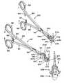
- FIG. 1is an exploded view of a cardiovascular valve assembly, according to an embodiment of the present invention, the valve assembly including an exchangeable valve member and a base member, and adapted for use in connection with the tools of the present invention;
- FIG. 2is a perspective view of the valve assembly of FIG. 1 , wherein the valve member is shown coupled to the base member;
- FIG. 3is an enlarged view of a portion of the valve assembly, showing a coupling element of the valve member engaged with a mounting portion of the base member;
- FIG. 4is a cross-sectional view taken along lines 4 - 4 of FIG. 3 ;
- FIG. 5is a perspective view of components of a multi-function valve exchange apparatus, which includes a holding tool, a removal tool and actuator tools, in accordance with a first embodiment of the present invention
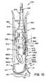
- FIG. 6is a cross-sectional view of the holding tool and the removal tool of the multi-function valve exchange apparatus shown in FIG. 5 , wherein the holding and removal tools are shown in their respective collapsed positions;
- FIG. 7is a cross-sectional view of the holding tool and the removal tool of the multi-function valve exchange apparatus, wherein the holding and removal tools are shown in their respective expanded positions, in relation to a cardiovascular valve assembly;
- FIG. 8is a cross-sectional view taken along lines 8 - 8 of FIG. 6 ;
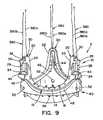
- FIG. 9is a perspective view of the valve assembly illustrating sutures attached thereto for guiding and locating the multi-function valve exchange apparatus to a position relative to the valve assembly, during a process for exchanging a valve member;
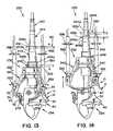
- FIG. 10is an elevational view illustrating the holding tool and the removal tool of the multi-function valve exchange apparatus, as guided into position relative to the valve assembly;
- FIG. 11is an elevational view of the multi-function valve exchange apparatus of FIG. 10 , illustrating the removal tool in engagement with the valve assembly;
- FIG. 12is an elevational view of the multi-function valve exchange apparatus of FIG. 10 , illustrating movement of the holding tool to an expanded position for engagement with the base member;
- FIG. 13is an elevational view of the multi-function valve exchange apparatus of FIG. 10 , illustrating movement of the removal tool to an expanded position to uncouple the valve member from the base member;
- FIG. 14is an elevational view of the multi-function valve exchange apparatus of FIG. 10 , illustrating movement of the removal tool relative to the holding tool to lift and separate the valve member from the base member;
- FIG. 15is an elevational view of the holding tool and an insertion tool of the multi-function valve exchange apparatus, illustrating the insertion tool being guided into position relative to the base member during a process for installing a replacement valve member;
- FIG. 16is an elevation view of the multi-function valve exchange apparatus shown in FIG. 15 , illustrating the insertion tool coupling the new valve member to the installed base member;
- FIG. 17is a perspective view of the multi-function valve exchange apparatus shown in FIG. 15 , illustrating the insertion tool coupling the new valve member to the installed base member;
- FIG. 18is a cross-sectional view taken across lines 18 - 18 of FIG. 16 ;
- FIG. 19is a perspective view of an alignment tool and a holding tool of a multi-function valve exchange apparatus according to another embodiment of the present invention, wherein the alignment tool is being guided into position relative to a valve assembly during a process to exchange an installed valve member;
- FIG. 20is a perspective view of the multi-function valve exchange apparatus shown in FIG. 19 , illustrating the alignment tool in engagement with the valve assembly;
- FIG. 21is a perspective view of the multi-function valve exchange apparatus shown in FIG. 19 , illustrating the holding tool being guided into position relative to the base member of the valve assembly;
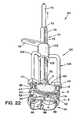
- FIG. 22is a perspective view of the multi-function valve exchange apparatus shown in FIG. 19 , illustrating the holding tool in an expanded position in engagement with the base member;
- FIG. 23is an enlarged perspective view of the engagement member of the holding tool of FIG. 22 , wherein the engagement member is in an expanded position, engaging with the base member;
- FIG. 24is an enlarged elevational view of the engagement member of the holding tool shown in FIG. 19 , wherein the engagement member is in a collapsed position;
- FIG. 25is an enlarged elevational view of the holding tool shown in FIG. 19 , wherein the holding tool is shown locked in a fully expanded position;
- FIG. 26is an elevational view of a removal tool of the multi-function valve exchange apparatus of FIG. 19 , illustrating the removal tool being guided into position relative to a valve assembly during the process to exchange the installed valve member;
- FIG. 27is a cross-sectional view of the multi-function valve exchange apparatus taken across lines 27 - 27 of FIG. 26 ;
- FIG. 28is an elevational view of the removal tool of FIG. 26 in an expanded position, engaging with the valve member of the valve assembly;
- FIG. 29is a cross-sectional view of the removal tool shown in FIG. 28 .
- FIG. 1shows an exploded view of a cardiovascular valve assembly 2 , according to an embodiment of the present invention.
- Valve assembly 2is adapted for use in connection with the tool set of the present invention, which is described below.
- Valve assembly 2is comprised of a docking station or base member 40 and a valve member 10 that is detachably coupled to base member 40 .
- FIG. 2shows valve member 10 coupled to base member 40 .
- valve member 10is a bioprosthetic valve. However, it is contemplated that valve member 10 may also take the form of a mechanical valve.
- Base member 40is generally comprised of a plurality of mounting portions 42 and a plurality of arcuate sections 48 located between mounting portions 42 .
- Mounting portions 42function as stent posts of base member 40 .
- Each mounting portion 42includes an outward extending protuberance or tab 44 .
- Mounting portions 42 and arcuate sections 48define a generally cylindrical recess 54 .
- a plurality of recesses 52are formed in base member 40 .
- Recesses 52are provided to allow a stabilizer or holding tool to engage and hold base member 40 , as will be explained below. Recesses 52 may take the form of a hole or depression formed in base member 40 .
- a sewing cuff or ring(not shown) made of Dacron®, or other medical grade fabric, is sewn to the outer surface of base member 40 using holes 56 located along the circumference of base member 40 .
- the sewing cuff or ringpermanently attaches base member 40 to the tissue of the heart.
- the sewing cuffmay also include a sleeve (not shown) to provide further coverage of the outer surface of base member 40 .
- Valve member 10is generally comprised of a frame 12 and a plurality of valve leaflets 11 (i.e., a leaflet set) supported by frame 12 .
- Frame 12includes a plurality of ribbon sections 14 and coupling elements 20 .
- Coupling elements 20function as stent posts of valve member 10 , and allow valve member 10 to be coupled and uncoupled from base member 40 , as will be described below.
- Each coupling element 20is comprised of a generally U-shaped portion 22 having lower and upper crossbars 24 , 26 extending across U-shaped portion 22 .
- Upper crossbar 26is T-shaped and includes a downward extending finger 28 .
- Finger 28 and lower crossbar 24define a lower slot 34 .
- Upper crossbar 26 and the top section of U-shaped portion 22define an upper slot 36 .
- a fabric cover (not shown) made of a medical grade clothmay be placed over each coupling element 20 .
- each coupling element 20includes an opening 30 in generally U-shaped portion 22 .
- Each ribbon section 14has a generally arcuate shape, and extends between coupling elements 20 . Ribbon sections 14 have an arcuate shape that matches the profile of arcuate sections 48 of base member 40 , thereby forming a seal therebetween when valve member 10 is coupled to base member 40 . This seal prevents blood leakage between valve member 10 and base member 40 .
- Frame 12is preferably made of a flexible material having suitable elasticity to allow frame 12 to collapse into a tight bundle for convenient removal and exchange of valve member 10 through small incisions or a trocar, and to facilitate the engagement and disengagement of coupling elements 20 and mounting portions 42 , as will be described below.
- frame 12is made of a medical grade polymer material, such as poly-ether-ether-ketone (PEEK), polyurethane or polycarbonate.
- PEEKpoly-ether-ether-ketone
- frame 12may alternatively be formed of a metal, including, but not limited to, Elgiloy, nitinol, stainless steel, platinum, gold, titanium, other biocompatible metals, and combinations thereof.
- leaflets 11are supported by frame 12 .
- leaflets 11may be sewn to ribbon sections 14 using holes 16 formed along the length of ribbon sections 14 .
- leaflets 11may be attached to ribbon sections 14 by appropriate means, such as sutures, clips, staples or other fastening devices.
- Leaflets 11may be made of suitable materials, including, but not limited to, bovine pericardium, equine pericardium, ovine pericardium, porcine aortic valve tissue, small intestinal submucosa (SIS), various biodegradable substrates for tissue engineered valves, and various relatively inert polymers, such as polyurethane. In order to improve clarity, leaflets 11 have been omitted from some figures illustrating the present invention.
- each pair of mounting portion 42 /coupling element 20provides a protuberance-slot mechanism, as best seen in FIGS. 3 and 4 .
- each coupling element 20provides a protuberance and each mounting portion 42 provides a slot.
- the entire protuberance-slot mechanismis covered by a cap (not shown) that prevents fibrotic ingrowth.
- All exposed surfaces of valve assembly 2are preferably covered by a fabric cover (not shown) made of Dacron®, or other medical grade fabric, as in conventional bioprosthetic valves.
- Valve member 10is coupled and uncoupled to/from base member 40 through engagement and disengagement of coupling elements 20 and mounting portion 42 .
- lower slot 34 of each coupling element 20is dimensioned to receive a respective tab 44 of each mounting portion 42 , thereby coupling valve member 10 to base member 40 .
- tab 44is captured between the lower surface of finger 28 of upper crossbar 26 and the upper surface of lower crossbar 24 .
- frame 12is formed of an elastic material. Accordingly, frame 12 is dilated by outward deflection to disengage tab 44 of each mounting portion 42 from lower slot 34 of each coupling element 20 . Consequently, valve member 10 is uncoupled from base member 40 .
- valve member 10Coupling and uncoupling of valve member 10 to/from base member 40 is facilitated by use of the tool set of the present invention, which is described in detail below.
- valve member 10Once valve member 10 is coupled to base member 40 , valve member 10 is secured such that it cannot unintentionally uncouple from base member 40 . In this respect, outward deflection of frame 12 is opposite to normal cardiac forces, thus providing secure engagement.
- Multi-function valve exchange apparatus 230is comprised of a stabilizer or holding tool 232 for holding base member 40 during a valve exchange procedure and a valve extraction or removal tool 234 for removing an existing valve member 10 from an installed base member 40 .
- Multi-function valve exchange apparatus 230may also include a valve insertion tool 400 for facilitating the installation of a replacement valve member 10 .
- Valve insertion tool 400will be described below with reference to FIGS. 15-18 .
- multi-function valve exchange apparatus 230also includes first and second actuator tools 180 and 220 ( FIG. 5 ) for actuation of multi-function valve exchange apparatus 230 . First and second actuator tools 180 and 220 are described below.
- Holding tool 232 and removal tool 234will now be described with reference to FIGS. 6-8 .
- Holding tool 232is generally comprised of a first elongated sliding member 242 , a second elongated sliding member 244 , an engagement member 270 and a nose cone 290 .
- Removal tool 234is generally comprised of a third elongated sliding member 246 , a fourth sliding member 248 , and an engagement member 340 .
- Sliding members 242 , 244 , 246 and 248are arranged to nest within each other in a telescoping manner, as seen in FIGS. 6 and 7 .
- first sliding member 242generally takes the form of a cylindrical rod having a first annular hub portion 254 at one end thereof.
- a slot 252extends along a portion of the length of the rod. Slot 252 is open at one end of first sliding member 242 .
- An annular channel 242 b that defines an annular flange 242 ais located at one end of first sliding member 242 .
- Annular channel 242 bis used in connection with the actuator tools described below.
- a plurality of slots 256are formed in first hub portion 254 . Pins 257 extend across slots 256 .
- second sliding member 244generally takes the form of a tubular sleeve having a second annular hub portion 264 .
- Second sliding member 244is dimensioned to receive first sliding member 242 such that first sliding member 242 is moveable relative to second sliding member 244 .
- a slot 262extends along a portion of the length of the sleeve. Slot 262 is open at one end of second sliding member 244 .
- An annular channel 244 b that defines an annular flange 244 ais located at one end of second sliding member 244 .
- Annular channel 244 bis used in connection with the actuator tools described below.
- a plurality of slots 266are formed in second hub portion 264 .
- Pins 267extend across slots 266 .
- a threaded recess 268is formed in hub portion 264 generally transverse to the longitudinal axis of second sliding member 244 .
- Engagement member 270includes a plurality of articulating joints 272 .
- Each joint 272is comprised of a link 274 and an arm 276 .
- a projection 278extends outward from one end of arm 276 , as seen in FIGS. 6 and 7 .
- Projection 278is dimensioned to be received by recesses 52 of base member 40 , as will be described below. It should be appreciated that projections 278 may have alternative shapes from the illustrated embodiment.
- Arm 276also includes a recess 280 to lock engagement member 270 in an expanded position, as will be explained below with reference to FIG. 7 .
- a first end of link 274is pivotally connected with first hub portion 254 of first sliding member 242 , and a second end of link 274 is pivotally connected with a first end of arm 276 .
- Each slot 256 of first hub portion 254is dimensioned to receive one end of a link 274 .
- the second end of arm 276is pivotally connected with second hub portion 264 of second sliding member 244 .
- Each slot 266 of second hub portion 264is dimensioned to receive one end of an arm 276 .
- Nose cone 290has a generally conical face 292 and an inner cavity 298 .
- Conical face 292facilitates insertion of valve exchange apparatus 230 through leaflets 11 of valve member 10 , thereby allowing valve exchange apparatus 230 to be properly located relative to valve assembly 2 during a process for exchanging a valve member 10 , as will be described below.
- Openings 295 formed in nose cone 290are dimensioned to receive fasteners 296 (e.g., screws) for attaching nose cone 290 to second hub portion 264 of second sliding member 244 .
- Inner cavity 298is dimensioned to receive first hub portion 254 of first sliding member 242 .
- Slots 294are formed in nose cone 290 , and are dimensioned to allow free movement of articulating joints 272 .
- engagement member 270moves between a collapsed position ( FIG. 6 ) and an expanded position ( FIG. 7 ).
- projections 278 of arms 276are received by recesses 52 of base member 40 in order to engage holding tool 232 therewith, as shown in FIG. 7 .
- a portion of each link 274is received into recess 280 of arm 276 , thereby locking engagement member 270 in the expanded position.
- removal tool 234is generally comprised of a third elongated sliding member 246 , a fourth sliding member 248 , and an engagement member 340 .
- third sliding member 246generally takes the form of a tubular sleeve having a third annular hub portion 304 at one end thereof.
- a slot 302extends along a portion of the length of the sleeve. Slot 302 is closed at both ends thereof.
- An annular channel 246 b that defines an annular flange 246 ais located at one end of third sliding member 246 . Annular channel 246 b is used in connection with the actuator tools described below.
- a plurality of slots 306are formed in third hub portion 304 .
- a pin 308extends across each slot 306 .
- fourth sliding member 248generally takes the form of a tubular collar having a fourth annular hub portion 324 .
- Fourth sliding member 248is dimensioned to receive third sliding member 246 such that fourth sliding member 248 is moveable relative to third sliding member 246 .
- third sliding member 246is dimensioned to receive first and second sliding members 242 , 244 such that removal tool 234 is moveable relative to holding tool 232 , as will be described below.
- annular channel 248 bthat defines an annular flange 248 a is located at one end of fourth sliding member 248 .
- Annular channel 248 bis used in connection with actuator tools described below.
- a plurality of slots 326are formed in fourth hub portion 324 , and a pin 328 extends across each slot.
- a threaded channel 330is formed in the fourth annular hub portion 324 generally transverse to the longitudinal axis of fourth sliding member 248 . Threaded channel 330 is dimensioned to receive an alignment pin 332 that extends through elongated slots 252 , 262 and 302 in order to properly orient first, second, third and fourth sliding members 242 , 244 , 246 , 248 relative to each other, as best seen in FIG. 8 .
- Elongated slots 252 and 262are open at one end to allow removal tool 234 to be dismounted from holding tool 232 , as will be explained below.
- Engagement member 340is generally comprised of a plurality of arms 342 and generally L-shaped caps 352 .
- a first end of arm 342is pivotally mounted to fourth hub portion 324 of fourth sliding member 248 .
- Each arm 342includes an L-shaped slot 344 dimensioned to receive pin 308 of third sliding member 246 . End 346 of L-shaped slot 344 captures pin 308 to lock engagement member 340 in an expanded position.
- Cap 352includes a slot 354 , as best seen in FIG. 8 .
- a pin 356is located across slot 354 to pivotally mount cap 352 to arm 342 .
- cap 352includes an outward extending body 362 and a pair of downward extending fingers 372 .
- Body 362has a curved inner surface 368 that generally matches the surface profile of upper surface of U-shaped portion 22 of valve member 10 (see FIG. 10 ).
- a recess 364is formed in body 362 adjacent to slot 354
- a notch 366is formed in the outer surface of body 362 .
- engagement member 340moves between a collapsed position ( FIG. 6 ) and an expanded position ( FIG. 7 ).
- caps 352are engaged with coupling elements 20 of valve member 10 , as will be explained in detail below.
- Arms 342are locked in position when engagement member 340 is moved to the fully expanded position.
- pin 308 of third hub portion 304is captured within end 346 of L-shaped slot 344 , as shown in FIG. 7 .
- Valve insertion tool 400is generally comprised of a tubular collar or guide sleeve 402 and an engagement member 420 .
- Guide sleeve 402includes a cylindrical recess 404 extending along the longitudinal axis thereof. Cylindrical recess 404 is dimensioned to receive first and second sliding members 242 , 244 of holding tool 232 , such that valve insertion tool 400 is moveable relative to holding tool 232 .
- a threaded opening 406extends through guide sleeve 402 generally transverse to cylindrical recess 404 .
- An alignment pin 408is threaded into opening 406 and extends into cylindrical recess 404 .
- Elongated slots 252 and 262 of first and second sliding members 242 , 244are dimensioned to receive alignment pin 408 , as shown in FIG. 18 .
- engagement member 420takes the form of a bracket having a mounting base 422 , a plurality of legs 424 , and a plurality of feet 426 respectively extending outward from each of the legs 424 .
- a pair of holes 428 a , 428 bare formed in each of the legs 424 .
- Base 422is mounted to lower surface 403 of guide sleeve 402 using a plurality fasteners 430 .
- fasteners 430are screws.
- engagement member 420may be integrally formed with guide sleeve 402 as a unitary component.
- actuator tool 180resembles a conventional surgical forceps.
- Actuator tool 180generally comprises a pair of elongated arms (first arm 182 and second arm 184 ), a first attachment plate 200 and a second attachment plate 210 .
- First and second arms 182 , 184are pivotally connected to one another in a scissors-like fashion by a pivotal connection 190 , such as a box or mortise type joint, as well known in the art.
- First and second arms 182 , 184have first and second finger grips 186 , 188 at a proximal end thereof, and have first and second jaws 192 , 194 at a distal end thereof, respectively.
- first jaw 192has a shorter length than second jaw 194 .
- First and second arms 182 , 184respectively include catches 187 and 189 that engage each other, so as to prevent separation of first and second grips 186 , 188 until a user applies a twisting movement in order to separate catches 187 , 189 from each other.
- First attachment plate 200is attached to the distal end of first jaw 192
- second attachment plate 210is attached to the distal end of second jaw 194 .
- first attachment plate 200has a pair of spaced-apart upward-extending side walls 204 a , 204 b that define a gap 206 therebetween.
- Holes 205are formed in side walls 204 a , 204 b to allow attachment plate 200 to be attached to the distal end of first jaw 192 .
- the free end of attachment plate 200has a forked portion 202 that defines a slot 203 .
- Gap 206 of first attachment plate 200is dimensioned to allow second jaw 194 to extend therethrough.
- Second attachment plate 210is connected to the distal end of second jaw 194 by fasteners.
- attachment plate 210has a forked portion 212 that defines a slot 213 .
- First and second attachment plates 200 , 210are attached to respective jaws 192 , 194 such that slots 203 and 213 are generally aligned with each other, as shown in FIG. 5 .
- first actuator tool 180In operation of first actuator tool 180 , movement of first and second grips 186 , 188 toward each other results in the movement of forked portions 202 , 212 away from each other. Likewise, movement of first and second grips 186 , 188 away from each other results in the movement of forked portions 202 , 212 toward each other.
- Second actuator tool 220 shown in FIG. 5is similar in many respects to first actuator tool 180 . Accordingly, similar components of second actuator tool 220 have the same reference numbers as like components of first actuator tool 180 .
- first and second jaws 192 a , 194 ahave substantially the same length. Attachment plates 210 a , 210 b having forked portions 212 a , 212 b are respectively attached to the distal end of each jaw 192 a , 194 a , such that the pair of slots 213 a , 213 b are generally aligned with each other, as shown in FIG. 5 .
- second actuator tool 220In operation of second actuator tool 220 , movement of first and second grips 186 , 188 toward each other results in the movement of the pair of forked portions 212 a , 212 b towards each other. Likewise, movement of first and second grips 186 , 188 away from each other results in the movement of the pair of forked portions 212 a , 212 b away from each other. Accordingly, second actuator tool 220 operates in a manner opposite to first actuator tool 180 , wherein movement of first and second grips 186 , 188 towards each other results in movement of forked portions 202 , 212 away from each other.
- a method for exchanging valve member 10 of an installed valve assembly 2 and the detailed operation of multi-function valve exchange apparatus 230will now be described in detail with particular reference to FIGS. 9-17 .
- the method for exchanging valve member 10includes threading a suture 380 through each opening 30 and upper slot 36 of valve member 10 , as shown in FIG. 9 .
- a needle(not shown) may be used to facilitate threading of sutures 380 .
- Sutures 380are guide wires that function as alignment guide means for locating holding tool 230 in a proper position relative to base member 40 of valve assembly 2 , as will be discussed below.
- sutures 380are stainless steel sutures.
- Removal tool 234is mounted onto holding tool 232 .
- removal tool 234is positioned such that alignment pin 332 is aligned with elongated slots 252 and 262 of first and second sliding members 242 , 244 , as shown in FIG. 8 .
- end 380 a of each suture 380is respectively threaded through recess 364 of caps 352 of removal tool 234 , and end 380 b of each suture 380 is respectively guided through notch 366 of caps 352 of removal tool 234 .
- Recess 364 and notch 366 of caps 352are best seen in FIG. 8 .
- Ends 380 a , 380 b of each suture 380are inserted through a respective tube 382 , as shown in FIG. 10 .
- tubes 382are made of a plastic material and have a length of about 10 inches (25.4 cm).
- Apparatus 230is guided along threaded sutures 380 to properly locate apparatus 230 relative to valve assembly 2 .
- apparatus 230is guided along threaded suture 380 such that curved inner surface 368 each cap 352 respectively abuts the top surface of U-shaped portions 22 of valve member 10 , as shown in FIG. 11 .
- apparatus 230is in an operating position wherein engagement member 270 of holding tool 232 is located proximate to recesses 52 of base member 40 .
- Clamp means 386are applied to each tube 382 once apparatus 230 is located at the operating position and tubes 382 are located relative to removal tool 234 such that tubes 382 abut the upper surface of caps 352 .
- Application of clamp means 386 to tubes 382restricts movement of caps 352 relative to valve member 10 .
- first actuator tool 180is engaged with holding tool 232 . More specifically, forked portions 202 , 212 capture the outer surface of first and second sliding members 242 , 244 within annular channels 242 b and 244 b , as shown in FIG. 12 . It should be appreciated that the location of forked portions 202 and 212 may be reversed with respect to the illustrated embodiment. First and second grips 186 , 188 are moved toward each other, thereby moving forked portions 202 , 212 away from each other. As a result, first sliding member 242 and second sliding member 244 will slide relative to each other such that channels 242 b and 244 b move away from each other.
- first and second sliding members 242 and 244Movement of first and second sliding members 242 and 244 in this manner causes engagement member 270 to move from a collapsed position to an expanded position.
- projections 278 of arms 276are received by recesses 52 of base member 40 in order to engage holding tool 232 therewith, as shown in FIG. 12 . Accordingly, holding tool 232 is securely engaged with base member 40 .
- First actuator tool 180is disengaged from holding tool 232 at the first location described above, and re-engaged with holding tool 232 such that forked portions 202 , 212 capture the outer surface of third and fourth sliding members 246 , 248 within annular channels 246 b and 248 b , as shown in FIG. 13 .
- First and second grips 186 , 188are moved toward each other, thereby moving forked portions 202 , 212 away from each other.
- third sliding member 246 and fourth sliding member 248will slide relative to each other such that channels 246 b and 248 b move away from each other.
- third and fourth sliding members 246 and 248moves from a collapsed position to an expanded position.
- caps 352 of removal tool 234move outward, thereby outwardly deflecting or dilating frame 12 of valve member 10 , as shown in FIG. 13 . Consequently, tab 44 of each mounting portion 42 disengages from lower slot 34 of each coupling element 20 , and valve member 10 uncouples from base member 40 .
- first actuator tool 180is disengaged from holding tool 232 , and second actuator tool 220 is engaged with removal tool 234 such that forked portions 212 a , 212 b capture the outer surface of second sliding member 244 of holding tool 232 and third sliding member 246 of removal tool 234 , within annular channels 244 b and 246 b ( FIG. 14 ).
- First and second grips 186 , 188are moved toward each other, thereby moving forked portions 212 a , 212 b toward each other.
- second sliding member 244 and third sliding member 246will slide relative to each other such that channels 244 b and 246 b move toward each other.
- Movement of second and third sliding members 244 , 246 in this mannercauses removal tool 234 to move relative to holding tool 232 , thereby lifting and separating valve member 10 from base member 40 , as shown in FIG. 14 .
- the valve removal processis completed by dismounting removal tool 234 from holding tool 232 by generally reversing the steps described above for mounting removal tool 234 onto holding tool 232 .
- insertion tool 400 of apparatus 230 to install a new valve member 10will now be described with particular reference to FIGS. 15-17 .
- a new valve member 10is attached to insertion tool 400 by sutures 390 .
- a suture 390is threaded through each upper slot 36 of valve member 10 and the pair of holes 428 a , 428 b of insertion tool 400 .
- insertion tool 400is mounted onto holding tool 232 .
- insertion tool 400is positioned such that pin 408 extending through guide sleeve 402 is aligned with elongated slots 252 and 262 of first and second sliding members 242 , 244 , as best seen in FIG. 18 .
- Guide sleeve 402slides along elongated slots 252 , 262 toward base member 40 .
- Forceis applied to insertion tool 400 to couple valve member 10 to base member 40 , as shown in FIGS. 16 and 17 .
- sutures 390are cut to separate valve member 10 from insertion tool 400 .
- insertion tool 400is dismounted from holding tool 232 by generally reversing the steps described above for mounting insertion tool 400 onto holding tool 232 .
- holding tool 232is disengaged from base member 40 by generally reversing the steps described above for engaging holding tool 232 with base member 40 .
- second actuator tool 220is engaged with holding tool 232 , wherein forked portions 212 a , 212 b capture the outer surface of first and second sliding members 242 , 244 within annular channels 242 b and 244 b .
- First and second grips 186 , 188are moved toward each other, thereby moving forked portions 212 a , 212 b toward each other.
- first sliding member 242 and second sliding member 244will slide relative to each other such that channels 242 b and 244 b move toward each other.
- first and second sliding members 242 and 244Movement of first and second sliding members 242 and 244 in this manner causes engagement member 270 to move from an expanded position to a collapsed position. Consequently, projections 278 of arms 276 are withdrawn by recesses 52 of base member 40 to disengage holding tool 232 therefrom. Holding tool 232 is then withdrawn from the patient. It will be appreciated that insertion tool 400 may remain mounted to holding tool 232 and removed simultaneously with removal of holding tool 232 .
- a multi-function valve exchange apparatus 60according to an alternative embodiment of the present invention will now be described with reference to FIGS. 19-29 .
- Multi-function valve exchange apparatus 60includes a stabilizer or holding tool 70 , an alignment tool 100 and an extraction or removal tool 130 . Removal tool 130 is shown with holding tool 70 in FIGS. 26-29 .
- Holding tool 70is generally comprised of a first sliding member 72 , a second sliding member 74 and an articulating engagement member 80 .
- first sliding member 72takes the form of a cylindrical rod
- second sliding member 74takes the form of a tubular sleeve.
- Second sliding member 74is dimensioned to receive first sliding member 72 such that first sliding member is moveable relative to second sliding member 74 .
- a plurality of ribs 75extend along the length of the outer surface of second sliding member 74 .
- An annular flange 76is located at the lower end of second sliding member 74 .
- a removable handle or tab 78snap-fits onto the outer surface of second sliding member 74 .
- a notch 77is formed in second sliding member 74 to locate tab 78 along the length of second sliding member 74 , as best seen in FIG. 28 .
- a spring-biased locking clip 73(best seen in FIG. 25 ) is located in first sliding member 72 in order to lock holding tool 70 in an expanded position, as will be described below.
- first sliding member 72is connected with second sliding member 74 by articulating engagement member 80 , while the other end of first sliding member 72 can be gripped to longitudinally move first sliding member 72 relative to second sliding member 74 .
- Articulating engagement member 80is comprised of a plurality of articulating joints 82 .
- Each articulating joint 82includes a link 84 and a leg 86 that are pivotally connected to each other.
- Link 84is also pivotally connected at one end with first sliding member 72 and leg 86 is also pivotally connected at one end with second sliding member 74 .
- a triangular wedge 88 having a projection 90 extending outward therefromis located at the free end of each leg 86 , as best seen in FIGS. 24 and 25 .
- Projections 90are dimensioned to be received by recesses 52 of base member 40 , as will be described below. It should be appreciated that projections 90 may have alternative shapes from the illustrated embodiment.
- engagement member 80moves between a collapsed position ( FIGS. 19-21 and 24 ) and an expanded position ( FIGS. 22-23 and 25 ).
- FIGS. 19 , 20 and 24triangular wedges 88 of legs 86 collectively form a conical-shaped tip when engagement member 80 is in the collapsed position.
- projections 90are received by recesses 52 of base member 40 in order to engage holding tool 70 therewith, as best seen in FIG. 23 .
- Alignment tool 100is generally comprised of a collar portion 102 and an engagement member 104 .
- Collar portion 102is dimensioned to mount over second sliding member 74 of holding tool 70
- a plurality of grooves 103extend along the length of the inner surface of collar portion 102 .
- Grooves 103are dimensioned to respectively receive ribs 75 of second sliding member 74 .
- Ribs 75 and grooves 103function to locate holding tool 70 in a proper position relative to valve member 40 , such that projections 90 of articulating engagement member 80 are aligned with respective recesses 52 of base member 40 when engagement member 80 is in the expanded position, as shown in FIGS. 22 and 23 .
- Engagement member 104is generally comprised of L-shaped arms 106 , caps 110 and generally U-shaped connecting members 116 .
- Arms 106extend outward from collar 102 .
- Caps 110are located at the distal end of arms 106 .
- Each cap 110has a recess 112 that is dimensioned to receive a top section of U-shaped portion 22 of coupling elements 20 .
- U-shaped connecting members 116take the form of loops that extend between adjacent caps 110 , and are dimensioned to generally match the surface contour of ribbon sections 14 of valve member 10 , as seen in FIGS. 20-22 .
- Removal tool 130functions to separate and remove valve member 10 from base member 40 , and is generally comprised of a body 132 , an engagement member 150 , and an actuator 160 .
- body 132includes a tubular section 134 , a conical section 136 and a sleeve 138 .
- Tubular section 134includes a threaded inner surface 135 , as shown in FIG. 29 .
- Sleeve 138includes an inner channel 139 having grooves 140 formed therein. As can be seen in FIG. 29 , the inner and outer diameters of tubular section 134 are respectively larger than the inner and outer diameters of sleeve 138 .
- Engagement member 150is generally comprised of a plurality of arms 152 and a plurality of respective bias members 154 .
- a first end of each arm 152is pivotally mounted to conical section 136 within slots formed therein.
- Arms 152include a projection 153 that extends outward therefrom.
- projections 153take the form of pins or hooks.
- Bias members 154extend downward from the outer surface of tubular section 134 , as best seen in FIG. 29 .
- bias members 154are comprised of a metal leaf spring having an inward extending contact element 155 at one end thereof. Bias members 154 bias arms 152 inward toward the outer surface of sleeve 138 .
- Actuator 160includes a threaded outer surface 161 and an annular flange 164 .
- Annular flange 164serves as a gripping element.
- An inner channel 166extends through actuator 160 .
- the threads of outer surface 161are dimensioned to mate with the threads of inner surface 135 of tubular section 134 .
- inner channel 166 of actuator 160is coaxial with inner channel 139 of sleeve 138 .
- front face 162 of actuator 160engages tapered surfaces 152 a of arms 152 , thereby causing arms 152 to pivot outward against the biasing force of bias members 154 ( FIG. 29 ). Accordingly, projections 153 of arms 152 extend outward, away from the outer surface of sleeve 138 .
- a method for exchanging valve member 10 of an installed valve assembly 2and the detailed operation of multi-function valve exchange apparatus 60 , comprised of holding tool 70 , alignment tool 100 and removal tool 130 , will now be described with particular reference to FIGS. 19-29 .
- alignment tool 100mounted onto holding tool 70 .
- collar portion 102is position such that grooves 103 are aligned with ribs 75 of second sliding member 74 .
- Alignment tool 100is then located relative to valve assembly 2 such that connecting members 116 are located adjacent to respective ribbon sections 14 of valve member 10 , thereby contacting leaflets 11 mounted to valve member 10 ( FIGS. 19 and 20 ).
- caps 110 of alignment tool 100are coarsely aligned with respective coupling elements 20 of valve member 10 .
- Additional positioning of alignment tool 100 relative to valve assembly 2is carried out by seating each cap 110 onto a respective U-shaped portion 22 of coupling elements 20 ( FIG. 29 ).
- holding tool 70is advanced toward valve assembly 2 by moving second sliding member 74 relative to collar portion 102 of alignment tool 100 , such that tab 78 abuts the top face of collar portion 102 , as shown in FIG. 21 .
- Engagement member 80is now properly positioned for engagement with base member 40 .
- engagement member 80is moved from the collapsed position ( FIGS. 20 , 21 and 24 ) to the expanded position ( FIGS. 22 , 23 and 25 ).
- holding tool 70is moved from the collapsed position to the expanded position by sliding first sliding member 72 relative to second sliding member 74 such that spring-biased locking clip 73 clears the top face of second sliding member 74 and springs outward, as best seen in FIG. 25 .
- first sliding member 72is moved relative to second sliding member 74
- legs 86 of engagement member 80expand outward, as shown in FIG. 25 .
- projections 90 of legs 86will be respectively received into recesses 52 of base member 40 , as best seen in FIG. 23 .
- Locking clip 73locks engagement member 80 in the expanded position.
- alignment tool 100is dismounted from holding tool 70 by generally reversing the steps described above for mounting alignment tool 100 onto holding tool 70 .
- tab 78is removed from notch 77 of second sliding member 74 , and collar portion 102 is moved relative to second sliding member 74 such that alignment tool 100 moves away from valve assembly 2 .
- removal tool 130is mounted to holding tool 70 by aligning grooves 140 of sleeve 138 with ribs 75 of second sliding member 74 , as best seen in FIG. 27 . Accordingly, removal tool 130 is pre-aligned with coupling elements 20 of valve member 10 . Removal tool 130 is moved relative to second sliding member 74 ( FIG. 26 ) such that the front face of sleeve 138 abuts flange 76 of second sliding member 74 ( FIG. 28 ). At this position, projections 153 of arms 152 are properly aligned relative to upper slots 36 of coupling elements 20 .
- Actuator 160 of removal tool 130is then rotated to outwardly expand arms 152 , as illustrated in FIG. 28 .
- Annular flange 164provides a gripping surface to facilitate rotation of actuator 160 .
- projections 152extend through respective upper slots 36 of coupling elements 20 .
- Additional rotation of actuator 160causes arms 152 to engage with coupling elements 20 , and outwardly deflect and dilate frame 12 such that lower slots 34 of coupling elements 20 are clear of tabs 44 of base member 40 . Accordingly, the outward expansion of arms 152 uncouples valve member 10 from base member 40 .
- Removal tool 130continues to engage and hold valve member 10 , and is dismounted from holding tool 70 by generally reversing the steps described above for mounting removal tool 130 onto holding tool 70 .
- removal tool 130is moved relative to second sliding member 74 such that removal tool 130 moves away base member 40 , thereby completing removal of valve member 10 .
- a new replacement valve member 10may be installed using a tool similar to the above-described valve insertion tool 400 , or a tool that functions similar to the above-described removal tool 130 .
- valve exchange procedureshave been described in connection with an “open chest” approach. It is contemplated that the methods and apparatus of the present invention are suitably adaptable for use in connection with a transapical approach. Furthermore, the location of projections/protuberances of the above-described tools and the mating recesses/slots of the valve assembly may be reversed, such that the projections/protuberances are located on the valve assembly and the mating recesses/slots are located on the tools.
Landscapes
- Health & Medical Sciences (AREA)
- Cardiology (AREA)
- Oral & Maxillofacial Surgery (AREA)
- Transplantation (AREA)
- Engineering & Computer Science (AREA)
- Biomedical Technology (AREA)
- Heart & Thoracic Surgery (AREA)
- Vascular Medicine (AREA)
- Life Sciences & Earth Sciences (AREA)
- Animal Behavior & Ethology (AREA)
- General Health & Medical Sciences (AREA)
- Public Health (AREA)
- Veterinary Medicine (AREA)
- Prostheses (AREA)
Abstract
Description
Claims (12)
Priority Applications (1)
| Application Number | Priority Date | Filing Date | Title |
|---|---|---|---|
| US13/063,218US8925164B2 (en) | 2008-09-12 | 2009-09-11 | Valve assembly with exchangeable valve member and a tool set for exchanging the valve member |
Applications Claiming Priority (3)
| Application Number | Priority Date | Filing Date | Title |
|---|---|---|---|
| US9654008P | 2008-09-12 | 2008-09-12 | |
| PCT/US2009/056633WO2010030859A1 (en) | 2008-09-12 | 2009-09-11 | Valve assembly with exchangeable valve member and a tool set for exchanging the valve member |
| US13/063,218US8925164B2 (en) | 2008-09-12 | 2009-09-11 | Valve assembly with exchangeable valve member and a tool set for exchanging the valve member |
Publications (2)
| Publication Number | Publication Date |
|---|---|
| US20110167603A1 US20110167603A1 (en) | 2011-07-14 |
| US8925164B2true US8925164B2 (en) | 2015-01-06 |
Family
ID=42005489
Family Applications (1)
| Application Number | Title | Priority Date | Filing Date |
|---|---|---|---|
| US13/063,218Expired - Fee RelatedUS8925164B2 (en) | 2008-09-12 | 2009-09-11 | Valve assembly with exchangeable valve member and a tool set for exchanging the valve member |
Country Status (4)
| Country | Link |
|---|---|
| US (1) | US8925164B2 (en) |
| EP (1) | EP2331015A1 (en) |
| CA (1) | CA2736817A1 (en) |
| WO (1) | WO2010030859A1 (en) |
Families Citing this family (10)
| Publication number | Priority date | Publication date | Assignee | Title |
|---|---|---|---|---|
| WO2012012660A2 (en)* | 2010-07-21 | 2012-01-26 | Accola Kevin D | Prosthetic heart valves and devices, systems, and methods for deploying prosthetic heart valves |
| GB2488530A (en)* | 2011-02-18 | 2012-09-05 | David J Wheatley | Heart valve |
| EP2688525B1 (en) | 2011-03-23 | 2019-08-21 | Daidalos Solutions B.V. | Medical instrument, ring prosthesis, stent and stented valve |
| US9414913B2 (en)* | 2013-10-25 | 2016-08-16 | Medtronic, Inc. | Stented prosthetic heart valve |
| US10022225B2 (en)* | 2014-07-23 | 2018-07-17 | Clemson University Research Foundation | Self-adjusting tissue holder |
| US10231829B2 (en) | 2016-05-04 | 2019-03-19 | Boston Scientific Scimed Inc. | Leaflet stitching backer |
| US11026787B2 (en)* | 2018-04-30 | 2021-06-08 | St. Jude Medical, Cardiology Division, Inc. | Heart valve holder |
| WO2021003167A1 (en)* | 2019-07-02 | 2021-01-07 | Edwards Lifesciences Corporation | Prosthetic heart valve and delivery apparatus therefor |
| US11524411B2 (en)* | 2021-01-29 | 2022-12-13 | Softwear Automation, Inc. | Automated product loading onto a pallet |
| CN115670749A (en)* | 2022-11-01 | 2023-02-03 | 苏州心锐医疗科技有限公司 | A replaceable heart polymer valve |
Citations (141)
| Publication number | Priority date | Publication date | Assignee | Title |
|---|---|---|---|---|
| US3409013A (en) | 1965-08-23 | 1968-11-05 | Berry Henry | Instrument for inserting artificial heart valves |
| US3839741A (en) | 1972-11-17 | 1974-10-08 | J Haller | Heart valve and retaining means therefor |
| US3872760A (en)* | 1973-07-12 | 1975-03-25 | Jr George J Desnoyers | Tool and method of using same |
| US3898701A (en) | 1974-01-17 | 1975-08-12 | Russa Joseph | Implantable heart valve |
| US4056854A (en) | 1976-09-28 | 1977-11-08 | The United States Of America As Represented By The Department Of Health, Education And Welfare | Aortic heart valve catheter |
| US4501030A (en) | 1981-08-17 | 1985-02-26 | American Hospital Supply Corporation | Method of leaflet attachment for prosthetic heart valves |
| US4506394A (en) | 1983-01-13 | 1985-03-26 | Molrose Management, Ltd. | Cardiac valve prosthesis holder |
| US4535483A (en) | 1983-01-17 | 1985-08-20 | Hemex, Inc. | Suture rings for heart valves |
| US4680031A (en) | 1982-11-29 | 1987-07-14 | Tascon Medical Technology Corporation | Heart valve prosthesis |
| US4687483A (en) | 1984-09-28 | 1987-08-18 | University Court Of The University Of Glasgow | Heart valve prosthesis |
| US4705516A (en) | 1983-04-20 | 1987-11-10 | Barone Hector D | Setting for a cardiac valve |
| US4733665A (en) | 1985-11-07 | 1988-03-29 | Expandable Grafts Partnership | Expandable intraluminal graft, and method and apparatus for implanting an expandable intraluminal graft |
| US4790843A (en) | 1986-06-16 | 1988-12-13 | Baxter Travenol Laboratories, Inc. | Prosthetic heart valve assembly |
| US4887605A (en) | 1988-02-18 | 1989-12-19 | Angelsen Bjorn A J | Laser catheter delivery system for controlled atheroma ablation combining laser angioplasty and intra-arterial ultrasonic imagining |
| US4909789A (en) | 1986-03-28 | 1990-03-20 | Olympus Optical Co., Ltd. | Observation assisting forceps |
| US4917698A (en) | 1988-12-22 | 1990-04-17 | Baxter International Inc. | Multi-segmented annuloplasty ring prosthesis |
| US5037427A (en) | 1987-03-25 | 1991-08-06 | Terumo Kabushiki Kaisha | Method of implanting a stent within a tubular organ of a living body and of removing same |
| US5041130A (en) | 1989-07-31 | 1991-08-20 | Baxter International Inc. | Flexible annuloplasty ring and holder |
| US5061275A (en) | 1986-04-21 | 1991-10-29 | Medinvent S.A. | Self-expanding prosthesis |
| US5071431A (en) | 1990-11-07 | 1991-12-10 | Carbomedics, Inc. | Suture rings for heart valves and method of securing suture rings to heart valves |
| US5087264A (en) | 1989-11-28 | 1992-02-11 | Olympus Optical Co., Ltd. | Venous valve-incising device |
| US5113846A (en) | 1990-07-03 | 1992-05-19 | Richard Wolf Gmbh | Organ manipulator |
| US5163953A (en) | 1992-02-10 | 1992-11-17 | Vince Dennis J | Toroidal artificial heart valve stent |
| US5197978A (en) | 1991-04-26 | 1993-03-30 | Advanced Coronary Technology, Inc. | Removable heat-recoverable tissue supporting device |
| US5234443A (en) | 1991-07-26 | 1993-08-10 | The Regents Of The University Of California | Endoscopic knot tying apparatus and methods |
| US5312360A (en) | 1990-11-20 | 1994-05-17 | Innerdyne Medical, Inc. | Tension guide and dilator |
| US5336230A (en) | 1992-11-04 | 1994-08-09 | Charles S. Taylor | Endoscopic suture tying method |
| US5411552A (en) | 1990-05-18 | 1995-05-02 | Andersen; Henning R. | Valve prothesis for implantation in the body and a catheter for implanting such valve prothesis |
| US5474563A (en) | 1993-03-25 | 1995-12-12 | Myler; Richard | Cardiovascular stent and retrieval apparatus |
| US5476510A (en) | 1994-04-21 | 1995-12-19 | Medtronic, Inc. | Holder for heart valve |
| WO1996014032A1 (en) | 1994-11-02 | 1996-05-17 | Duran Carlos M G | Bioprosthetic heart valve with absorbable stent |
| US5545214A (en) | 1991-07-16 | 1996-08-13 | Heartport, Inc. | Endovascular aortic valve replacement |
| US5549665A (en) | 1993-06-18 | 1996-08-27 | London Health Association | Bioprostethic valve |
| US5554185A (en) | 1994-07-18 | 1996-09-10 | Block; Peter C. | Inflatable prosthetic cardiovascular valve for percutaneous transluminal implantation of same |
| US5571174A (en) | 1991-01-24 | 1996-11-05 | Autogenics | Method of assembling a tissue heart valve |
| US5584803A (en) | 1991-07-16 | 1996-12-17 | Heartport, Inc. | System for cardiac procedures |
| US5593424A (en) | 1994-08-10 | 1997-01-14 | Segmed, Inc. | Apparatus and method for reducing and stabilizing the circumference of a vascular structure |
| US5607446A (en) | 1995-01-31 | 1997-03-04 | Beehler; Cecil C. | Pupil dilator |
| US5662676A (en) | 1992-06-24 | 1997-09-02 | K.U. Leuven Research & Development | Instrument set for laparoscopic hysterectomy |
| US5667525A (en) | 1994-08-25 | 1997-09-16 | Olympus Optical Co. | Grasping forceps for endoscope |
| US5718725A (en) | 1992-12-03 | 1998-02-17 | Heartport, Inc. | Devices and methods for intracardiac procedures |
| US5755783A (en) | 1996-07-29 | 1998-05-26 | Stobie; Robert | Suture rings for rotatable artificial heart valves |
| US5807405A (en) | 1995-09-11 | 1998-09-15 | St. Jude Medical, Inc. | Apparatus for attachment of heart valve holder to heart valve prosthesis |
| US5814054A (en) | 1996-09-23 | 1998-09-29 | Symbiosis Corporation | Automatic needle-passer suturing instrument |
| US5840081A (en) | 1990-05-18 | 1998-11-24 | Andersen; Henning Rud | System and method for implanting cardiac valves |
| US5843103A (en) | 1997-03-06 | 1998-12-01 | Scimed Life Systems, Inc. | Shaped wire rotational atherectomy device |
| US5843181A (en) | 1994-04-18 | 1998-12-01 | Hancock Jaffe Laboratories | Biological material pre-fixation treatment |
| US5855601A (en) | 1996-06-21 | 1999-01-05 | The Trustees Of Columbia University In The City Of New York | Artificial heart valve and method and device for implanting the same |
| US5910170A (en) | 1997-12-17 | 1999-06-08 | St. Jude Medical, Inc. | Prosthetic heart valve stent utilizing mounting clips |
| US5910144A (en) | 1998-01-09 | 1999-06-08 | Endovascular Technologies, Inc. | Prosthesis gripping system and method |
| WO1999033414A1 (en) | 1997-12-29 | 1999-07-08 | Ivan Vesely | System for minimally invasive insertion of a bioprosthetic heart valve |
| US5928281A (en) | 1997-03-27 | 1999-07-27 | Baxter International Inc. | Tissue heart valves |
| US5957949A (en) | 1997-05-01 | 1999-09-28 | World Medical Manufacturing Corp. | Percutaneous placement valve stent |
| US5961545A (en) | 1997-01-17 | 1999-10-05 | Meadox Medicals, Inc. | EPTFE graft-stent composite device |
| US5968070A (en) | 1995-02-22 | 1999-10-19 | Cordis Corporation | Covered expanding mesh stent |
| WO1999053845A1 (en) | 1998-04-20 | 1999-10-28 | St. Jude Medical, Inc. | Driver tool for heart valve prosthesis fasteners |
| US6004328A (en) | 1997-06-19 | 1999-12-21 | Solar; Ronald J. | Radially expandable intraluminal stent and delivery catheter therefore and method of using the same |
| US6071263A (en) | 1992-03-02 | 2000-06-06 | Kirkman; Thomas R. | Apparatus and method for retaining a catheter in a blood vessel in a fixed position |
| US6106550A (en) | 1998-07-10 | 2000-08-22 | Sulzer Carbomedics Inc. | Implantable attaching ring |
| US6156055A (en) | 1999-03-23 | 2000-12-05 | Nitinol Medical Technologies Inc. | Gripping device for implanting, repositioning or extracting an object within a body vessel |
| US6168616B1 (en) | 1997-06-02 | 2001-01-02 | Global Vascular Concepts | Manually expandable stent |
| US6187016B1 (en) | 1999-09-14 | 2001-02-13 | Daniel G. Hedges | Stent retrieval device |
| US6197054B1 (en) | 1998-09-01 | 2001-03-06 | Sulzer Carbomedics Inc. | Sutureless cuff for heart valves |
| US6217585B1 (en) | 1996-08-16 | 2001-04-17 | Converge Medical, Inc. | Mechanical stent and graft delivery system |
| US20010002445A1 (en) | 1997-12-29 | 2001-05-31 | The Cleveland Clinic Foundation | Bioprosthetic cardiovascular valve system |
| US6249952B1 (en) | 1997-08-04 | 2001-06-26 | Scimed Life Systems, Inc. | Method for manufacturing an expandable stent |
| WO2000047139A9 (en) | 1999-02-10 | 2001-09-13 | Heartport Inc | Methods and devices for implanting cardiac valves |
| US6299638B1 (en) | 1999-06-10 | 2001-10-09 | Sulzer Carbomedics Inc. | Method of attachment of large-bore aortic graft to an aortic valve |
| US6312465B1 (en) | 1999-07-23 | 2001-11-06 | Sulzer Carbomedics Inc. | Heart valve prosthesis with a resiliently deformable retaining member |
| US6371983B1 (en) | 1999-10-04 | 2002-04-16 | Ernest Lane | Bioprosthetic heart valve |
| US6383205B1 (en) | 1997-09-30 | 2002-05-07 | Target Therapeutics, Inc. | Mechanical clot treatment device with distal filter |
| US20020055775A1 (en) | 1999-01-26 | 2002-05-09 | Alain F. Carpentier | Flexible heart valve |
| US20020128702A1 (en) | 2000-10-09 | 2002-09-12 | Wolfgang Menz | Device for supporting a surgical step in a vessel, particularly for removal and implantation of heart valves |
| US6454799B1 (en) | 2000-04-06 | 2002-09-24 | Edwards Lifesciences Corporation | Minimally-invasive heart valves and methods of use |
| US6461382B1 (en) | 2000-09-22 | 2002-10-08 | Edwards Lifesciences Corporation | Flexible heart valve having moveable commissures |
| US20020173811A1 (en) | 2001-05-21 | 2002-11-21 | Hosheng Tu | Apparatus and methods for valve removal |
| US6508827B1 (en) | 1998-01-14 | 2003-01-21 | Karl Storz Gmbh & Co. Kg | Instrument for application in endoscopic surgery |
| US20030055495A1 (en) | 2001-03-23 | 2003-03-20 | Pease Matthew L. | Rolled minimally-invasive heart valves and methods of manufacture |
| US6562065B1 (en) | 1998-03-30 | 2003-05-13 | Conor Medsystems, Inc. | Expandable medical device with beneficial agent delivery mechanism |
| US6579305B1 (en) | 1995-12-07 | 2003-06-17 | Medtronic Ave, Inc. | Method and apparatus for delivery deployment and retrieval of a stent comprising shape-memory material |
| US6629534B1 (en) | 1999-04-09 | 2003-10-07 | Evalve, Inc. | Methods and apparatus for cardiac valve repair |
| US6663664B1 (en) | 2000-10-26 | 2003-12-16 | Advanced Cardiovascular Systems, Inc. | Self-expanding stent with time variable radial force |
| US20040015232A1 (en) | 2002-07-16 | 2004-01-22 | Medtronic, Inc. | Suturing rings for implantable heart valve prosthesis |
| US20040030381A1 (en) | 2002-07-16 | 2004-02-12 | Shu Mark C.S. | Heart valve prosthesis |
| US6733525B2 (en) | 2001-03-23 | 2004-05-11 | Edwards Lifesciences Corporation | Rolled minimally-invasive heart valves and methods of use |
| US20040147939A1 (en) | 2001-04-27 | 2004-07-29 | Intek Technology, L.L.C. | Apparatus for delivering, repositioning and/or retrieving self-expanding stents |
| US6769434B2 (en) | 2000-06-30 | 2004-08-03 | Viacor, Inc. | Method and apparatus for performing a procedure on a cardiac valve |
| US20040186563A1 (en) | 2003-03-18 | 2004-09-23 | Lobbi Mario M. | Minimally-invasive heart valve with cusp positioners |
| US20040225356A1 (en) | 2003-05-09 | 2004-11-11 | Frater Robert W. | Flexible heart valve |
| US6821297B2 (en) | 2000-02-02 | 2004-11-23 | Robert V. Snyders | Artificial heart valve, implantation instrument and method therefor |
| US20050075717A1 (en) | 2003-10-06 | 2005-04-07 | Nguyen Tuoc Tan | Minimally invasive valve replacement system |
| US6893459B1 (en)* | 2000-09-20 | 2005-05-17 | Ample Medical, Inc. | Heart valve annulus device and method of using same |
| US20050137692A1 (en) | 2003-12-23 | 2005-06-23 | Haug Ulrich R. | Methods and apparatus for endovascularly replacing a patient's heart valve |
| US20050159811A1 (en) | 2001-12-27 | 2005-07-21 | Ernest Lane | Bioprosthetic heart valve |
| US20050165479A1 (en) | 2004-01-26 | 2005-07-28 | Drews Michael J. | Heart valve assembly and methods for using them |
| US20050203618A1 (en) | 2003-12-10 | 2005-09-15 | Adam Sharkawy | Prosthetic cardiac valves and systems and methods for implanting thereof |
| US20050203614A1 (en) | 2004-02-27 | 2005-09-15 | Cardiacmd, Inc. | Prosthetic heart valves, scaffolding structures, and systems and methods for implantation of same |
| US20050228495A1 (en) | 2004-01-15 | 2005-10-13 | Macoviak John A | Suspended heart valve devices, systems, and methods for supplementing, repairing, or replacing a native heart valve |
| US20050228494A1 (en) | 2004-03-29 | 2005-10-13 | Salvador Marquez | Controlled separation heart valve frame |
| US20050283231A1 (en) | 2004-06-16 | 2005-12-22 | Haug Ulrich R | Everting heart valve |
| US7041132B2 (en) | 2002-08-16 | 2006-05-09 | 3F Therapeutics, Inc, | Percutaneously delivered heart valve and delivery means thereof |
| US7063707B2 (en) | 2002-03-06 | 2006-06-20 | Scimed Life Systems, Inc. | Medical retrieval device |
| US20060136052A1 (en) | 2004-12-16 | 2006-06-22 | Valvexchange Inc. | Cardiovascular valve assembly |
| US20060195180A1 (en) | 2005-02-25 | 2006-08-31 | Arash Kheradvar | Implantable small percutaneous valve and methods of delivery |
| US7105009B2 (en)* | 2002-10-16 | 2006-09-12 | Applied Medical Resources Corporation | Access device maintenance apparatus and method |
| US20060259134A1 (en) | 2003-07-08 | 2006-11-16 | Ehud Schwammenthal | Implantable prosthetic devices particularly for transarterial delivery in the treatment of aortic stenosis, and methods of implanting such devices |
| US20060287717A1 (en) | 2005-05-24 | 2006-12-21 | Rowe Stanton J | Methods for rapid deployment of prosthetic heart valves |
| US20070016288A1 (en) | 2005-07-13 | 2007-01-18 | Gurskis Donnell W | Two-piece percutaneous prosthetic heart valves and methods for making and using them |
| US20070027535A1 (en) | 2005-07-28 | 2007-02-01 | Cook Incorporated | Implantable thromboresistant valve |
| US7201761B2 (en) | 2001-06-29 | 2007-04-10 | Medtronic, Inc. | Method and apparatus for resecting and replacing an aortic valve |
| US20070088431A1 (en) | 2005-10-18 | 2007-04-19 | Henry Bourang | Heart valve delivery system with valve catheter |
| US7235093B2 (en) | 2003-05-20 | 2007-06-26 | Boston Scientific Scimed, Inc. | Mechanism to improve stent securement |
| US20070260305A1 (en) | 2006-04-29 | 2007-11-08 | Drews Michael J | Guide shields for multiple component prosthetic heart valve assemblies and apparatus and methods for using them |
| US20080004696A1 (en) | 2006-06-29 | 2008-01-03 | Valvexchange Inc. | Cardiovascular valve assembly with resizable docking station |
| US7323003B2 (en) | 2004-02-13 | 2008-01-29 | Boston Scientific Scimed, Inc. | Centering intravascular filters and devices and methods for deploying and retrieving intravascular filters |
| US20080033545A1 (en) | 2006-08-02 | 2008-02-07 | Medtronic, Inc. | Heart valve holder for use in valve implantation procedures |
| US7329279B2 (en) | 2003-12-23 | 2008-02-12 | Sadra Medical, Inc. | Methods and apparatus for endovascularly replacing a patient's heart valve |
| US20080065011A1 (en) | 2006-09-08 | 2008-03-13 | Philippe Marchand | Integrated heart valve delivery system |
| US20080071367A1 (en) | 2006-08-02 | 2008-03-20 | Bergin Cathleen A | Heart valve holder for use in valve implantation procedures |
| US20080082164A1 (en) | 2006-10-02 | 2008-04-03 | Friedman Robert S | Sutureless heart valve attachment |
| WO2008051428A2 (en) | 2006-10-23 | 2008-05-02 | Valvexchange Inc. | Cardiovascular valve and assembly |
| US7381219B2 (en) | 2003-12-23 | 2008-06-03 | Sadra Medical, Inc. | Low profile heart valve and delivery system |
| USRE40377E1 (en) | 1996-02-23 | 2008-06-10 | Cardiovascular Technologies Llc | Means and method of replacing a heart valve in a minimally invasive manner |
| WO2008088835A1 (en) | 2007-01-18 | 2008-07-24 | Valvexchange Inc. | Tools for removal and installation of exchangeable cardiovascular valves |
| US20080195199A1 (en) | 2007-01-08 | 2008-08-14 | Arash Kheradvar | In-situ formation of a valve |
| US20080228254A1 (en) | 2007-02-16 | 2008-09-18 | Ryan Timothy R | Delivery systems and methods of implantation for replacement prosthetic heart valves |
| WO2009026272A1 (en) | 2007-08-21 | 2009-02-26 | Valvexchange Inc. | Method and apparatus for prosthetic valve removal |
| US7544206B2 (en) | 2001-06-29 | 2009-06-09 | Medtronic, Inc. | Method and apparatus for resecting and replacing an aortic valve |
| US20100036484A1 (en) | 2008-06-06 | 2010-02-11 | Edwards Lifesciences Corporation | Low profile transcatheter heart valve |
| US7815676B2 (en) | 2006-07-07 | 2010-10-19 | The Cleveland Clinic Foundation | Apparatus and method for assisting in the removal of a cardiac valve |
| US7824442B2 (en) | 2003-12-23 | 2010-11-02 | Sadra Medical, Inc. | Methods and apparatus for endovascularly replacing a heart valve |
| US7824443B2 (en) | 2003-12-23 | 2010-11-02 | Sadra Medical, Inc. | Medical implant delivery and deployment tool |
| US7959666B2 (en) | 2003-12-23 | 2011-06-14 | Sadra Medical, Inc. | Methods and apparatus for endovascularly replacing a heart valve |
| US7959672B2 (en) | 2003-12-23 | 2011-06-14 | Sadra Medical | Replacement valve and anchor |
| US7993362B2 (en) | 2005-02-16 | 2011-08-09 | Boston Scientific Scimed, Inc. | Filter with positioning and retrieval devices and methods |
| US8025668B2 (en) | 2005-04-28 | 2011-09-27 | C. R. Bard, Inc. | Medical device removal system |
| US20110257735A1 (en) | 2003-12-23 | 2011-10-20 | Sadra Medical, Inc. | Systems and methods for delivering a medical implant |
| US20120041549A1 (en) | 2003-12-23 | 2012-02-16 | Sadra Medical, Inc. | Repositionable heart valve and method |
| US20120046740A1 (en) | 2004-11-05 | 2012-02-23 | Sadra Medical, Inc. | Medical devices and delivery systems for delivering medical devices |
| US20120053683A1 (en) | 2003-12-23 | 2012-03-01 | Sadra Medical, Inc. | Leaflet engagement elements and methods for use thereof |
| US20120078354A1 (en) | 2001-06-29 | 2012-03-29 | Cohn William E | Apparatus for replacing a cardiac valve |
Family Cites Families (1)
| Publication number | Priority date | Publication date | Assignee | Title |
|---|---|---|---|---|
| US6812624B1 (en)* | 1999-07-20 | 2004-11-02 | Sri International | Electroactive polymers |
- 2009
- 2009-09-11WOPCT/US2009/056633patent/WO2010030859A1/enactiveApplication Filing
- 2009-09-11USUS13/063,218patent/US8925164B2/ennot_activeExpired - Fee Related
- 2009-09-11EPEP09813659Apatent/EP2331015A1/ennot_activeWithdrawn
- 2009-09-11CACA2736817Apatent/CA2736817A1/ennot_activeAbandoned
Patent Citations (160)
| Publication number | Priority date | Publication date | Assignee | Title |
|---|---|---|---|---|
| US3409013A (en) | 1965-08-23 | 1968-11-05 | Berry Henry | Instrument for inserting artificial heart valves |
| US3839741A (en) | 1972-11-17 | 1974-10-08 | J Haller | Heart valve and retaining means therefor |
| US3872760A (en)* | 1973-07-12 | 1975-03-25 | Jr George J Desnoyers | Tool and method of using same |
| US3898701A (en) | 1974-01-17 | 1975-08-12 | Russa Joseph | Implantable heart valve |
| US4056854A (en) | 1976-09-28 | 1977-11-08 | The United States Of America As Represented By The Department Of Health, Education And Welfare | Aortic heart valve catheter |
| US4501030A (en) | 1981-08-17 | 1985-02-26 | American Hospital Supply Corporation | Method of leaflet attachment for prosthetic heart valves |
| US4680031A (en) | 1982-11-29 | 1987-07-14 | Tascon Medical Technology Corporation | Heart valve prosthesis |
| US4506394A (en) | 1983-01-13 | 1985-03-26 | Molrose Management, Ltd. | Cardiac valve prosthesis holder |
| US4535483A (en) | 1983-01-17 | 1985-08-20 | Hemex, Inc. | Suture rings for heart valves |
| US4705516A (en) | 1983-04-20 | 1987-11-10 | Barone Hector D | Setting for a cardiac valve |
| US4687483A (en) | 1984-09-28 | 1987-08-18 | University Court Of The University Of Glasgow | Heart valve prosthesis |
| US4733665A (en) | 1985-11-07 | 1988-03-29 | Expandable Grafts Partnership | Expandable intraluminal graft, and method and apparatus for implanting an expandable intraluminal graft |
| US4733665C2 (en) | 1985-11-07 | 2002-01-29 | Expandable Grafts Partnership | Expandable intraluminal graft and method and apparatus for implanting an expandable intraluminal graft |
| US4733665B1 (en) | 1985-11-07 | 1994-01-11 | Expandable Grafts Partnership | Expandable intraluminal graft,and method and apparatus for implanting an expandable intraluminal graft |
| US4909789A (en) | 1986-03-28 | 1990-03-20 | Olympus Optical Co., Ltd. | Observation assisting forceps |
| US5061275A (en) | 1986-04-21 | 1991-10-29 | Medinvent S.A. | Self-expanding prosthesis |
| US4790843A (en) | 1986-06-16 | 1988-12-13 | Baxter Travenol Laboratories, Inc. | Prosthetic heart valve assembly |
| US5037427A (en) | 1987-03-25 | 1991-08-06 | Terumo Kabushiki Kaisha | Method of implanting a stent within a tubular organ of a living body and of removing same |
| US4887605A (en) | 1988-02-18 | 1989-12-19 | Angelsen Bjorn A J | Laser catheter delivery system for controlled atheroma ablation combining laser angioplasty and intra-arterial ultrasonic imagining |
| US4917698A (en) | 1988-12-22 | 1990-04-17 | Baxter International Inc. | Multi-segmented annuloplasty ring prosthesis |
| US5041130A (en) | 1989-07-31 | 1991-08-20 | Baxter International Inc. | Flexible annuloplasty ring and holder |
| US5087264A (en) | 1989-11-28 | 1992-02-11 | Olympus Optical Co., Ltd. | Venous valve-incising device |
| US5411552A (en) | 1990-05-18 | 1995-05-02 | Andersen; Henning R. | Valve prothesis for implantation in the body and a catheter for implanting such valve prothesis |
| US6168614B1 (en) | 1990-05-18 | 2001-01-02 | Heartport, Inc. | Valve prosthesis for implantation in the body |
| US5840081A (en) | 1990-05-18 | 1998-11-24 | Andersen; Henning Rud | System and method for implanting cardiac valves |
| US5113846A (en) | 1990-07-03 | 1992-05-19 | Richard Wolf Gmbh | Organ manipulator |
| US5071431A (en) | 1990-11-07 | 1991-12-10 | Carbomedics, Inc. | Suture rings for heart valves and method of securing suture rings to heart valves |
| US5312360A (en) | 1990-11-20 | 1994-05-17 | Innerdyne Medical, Inc. | Tension guide and dilator |
| US5571174A (en) | 1991-01-24 | 1996-11-05 | Autogenics | Method of assembling a tissue heart valve |
| US5197978A (en) | 1991-04-26 | 1993-03-30 | Advanced Coronary Technology, Inc. | Removable heat-recoverable tissue supporting device |
| US5197978B1 (en) | 1991-04-26 | 1996-05-28 | Advanced Coronary Tech | Removable heat-recoverable tissue supporting device |
| US5545214A (en) | 1991-07-16 | 1996-08-13 | Heartport, Inc. | Endovascular aortic valve replacement |
| US5584803A (en) | 1991-07-16 | 1996-12-17 | Heartport, Inc. | System for cardiac procedures |
| US5234443A (en) | 1991-07-26 | 1993-08-10 | The Regents Of The University Of California | Endoscopic knot tying apparatus and methods |
| US5163953A (en) | 1992-02-10 | 1992-11-17 | Vince Dennis J | Toroidal artificial heart valve stent |
| US6071263A (en) | 1992-03-02 | 2000-06-06 | Kirkman; Thomas R. | Apparatus and method for retaining a catheter in a blood vessel in a fixed position |
| US5662676A (en) | 1992-06-24 | 1997-09-02 | K.U. Leuven Research & Development | Instrument set for laparoscopic hysterectomy |
| US5336230A (en) | 1992-11-04 | 1994-08-09 | Charles S. Taylor | Endoscopic suture tying method |
| US5718725A (en) | 1992-12-03 | 1998-02-17 | Heartport, Inc. | Devices and methods for intracardiac procedures |
| US5474563A (en) | 1993-03-25 | 1995-12-12 | Myler; Richard | Cardiovascular stent and retrieval apparatus |
| US5549665A (en) | 1993-06-18 | 1996-08-27 | London Health Association | Bioprostethic valve |
| US5843181A (en) | 1994-04-18 | 1998-12-01 | Hancock Jaffe Laboratories | Biological material pre-fixation treatment |
| US5476510A (en) | 1994-04-21 | 1995-12-19 | Medtronic, Inc. | Holder for heart valve |
| US5554185A (en) | 1994-07-18 | 1996-09-10 | Block; Peter C. | Inflatable prosthetic cardiovascular valve for percutaneous transluminal implantation of same |
| US5593424A (en) | 1994-08-10 | 1997-01-14 | Segmed, Inc. | Apparatus and method for reducing and stabilizing the circumference of a vascular structure |
| US5667525A (en) | 1994-08-25 | 1997-09-16 | Olympus Optical Co. | Grasping forceps for endoscope |
| WO1996014032A1 (en) | 1994-11-02 | 1996-05-17 | Duran Carlos M G | Bioprosthetic heart valve with absorbable stent |
| US5607446A (en) | 1995-01-31 | 1997-03-04 | Beehler; Cecil C. | Pupil dilator |
| US5968070A (en) | 1995-02-22 | 1999-10-19 | Cordis Corporation | Covered expanding mesh stent |
| US5807405A (en) | 1995-09-11 | 1998-09-15 | St. Jude Medical, Inc. | Apparatus for attachment of heart valve holder to heart valve prosthesis |
| US6579305B1 (en) | 1995-12-07 | 2003-06-17 | Medtronic Ave, Inc. | Method and apparatus for delivery deployment and retrieval of a stent comprising shape-memory material |
| USRE40377E1 (en) | 1996-02-23 | 2008-06-10 | Cardiovascular Technologies Llc | Means and method of replacing a heart valve in a minimally invasive manner |
| US5855601A (en) | 1996-06-21 | 1999-01-05 | The Trustees Of Columbia University In The City Of New York | Artificial heart valve and method and device for implanting the same |
| US5755783A (en) | 1996-07-29 | 1998-05-26 | Stobie; Robert | Suture rings for rotatable artificial heart valves |
| US6143025A (en) | 1996-07-29 | 2000-11-07 | Edwards Lifesciences Corporation | Suture rings for rotatable artificial heart valves |
| US6217585B1 (en) | 1996-08-16 | 2001-04-17 | Converge Medical, Inc. | Mechanical stent and graft delivery system |
| US5814054A (en) | 1996-09-23 | 1998-09-29 | Symbiosis Corporation | Automatic needle-passer suturing instrument |
| US5961545A (en) | 1997-01-17 | 1999-10-05 | Meadox Medicals, Inc. | EPTFE graft-stent composite device |
| US5843103A (en) | 1997-03-06 | 1998-12-01 | Scimed Life Systems, Inc. | Shaped wire rotational atherectomy device |
| US5928281A (en) | 1997-03-27 | 1999-07-27 | Baxter International Inc. | Tissue heart valves |
| US5957949A (en) | 1997-05-01 | 1999-09-28 | World Medical Manufacturing Corp. | Percutaneous placement valve stent |
| US6168616B1 (en) | 1997-06-02 | 2001-01-02 | Global Vascular Concepts | Manually expandable stent |
| US6004328A (en) | 1997-06-19 | 1999-12-21 | Solar; Ronald J. | Radially expandable intraluminal stent and delivery catheter therefore and method of using the same |
| US6249952B1 (en) | 1997-08-04 | 2001-06-26 | Scimed Life Systems, Inc. | Method for manufacturing an expandable stent |
| US6383205B1 (en) | 1997-09-30 | 2002-05-07 | Target Therapeutics, Inc. | Mechanical clot treatment device with distal filter |
| US5910170A (en) | 1997-12-17 | 1999-06-08 | St. Jude Medical, Inc. | Prosthetic heart valve stent utilizing mounting clips |
| WO1999033414A1 (en) | 1997-12-29 | 1999-07-08 | Ivan Vesely | System for minimally invasive insertion of a bioprosthetic heart valve |
| US20030125793A1 (en) | 1997-12-29 | 2003-07-03 | The Cleveland Clinic Foundation | Bioprosthetic cardiovascular valve system |
| US20010002445A1 (en) | 1997-12-29 | 2001-05-31 | The Cleveland Clinic Foundation | Bioprosthetic cardiovascular valve system |
| US7011681B2 (en) | 1997-12-29 | 2006-03-14 | The Cleveland Clinic Foundation | Bioprosthetic cardiovascular valve system |
| US20060135964A1 (en) | 1997-12-29 | 2006-06-22 | The Cleveland Clinic Foundation | Bioprosthetic cardiovascular valve system |
| US6569196B1 (en) | 1997-12-29 | 2003-05-27 | The Cleveland Clinic Foundation | System for minimally invasive insertion of a bioprosthetic heart valve |
| US6530952B2 (en) | 1997-12-29 | 2003-03-11 | The Cleveland Clinic Foundation | Bioprosthetic cardiovascular valve system |
| US5910144A (en) | 1998-01-09 | 1999-06-08 | Endovascular Technologies, Inc. | Prosthesis gripping system and method |
| US6508827B1 (en) | 1998-01-14 | 2003-01-21 | Karl Storz Gmbh & Co. Kg | Instrument for application in endoscopic surgery |
| US6562065B1 (en) | 1998-03-30 | 2003-05-13 | Conor Medsystems, Inc. | Expandable medical device with beneficial agent delivery mechanism |
| US6074418A (en) | 1998-04-20 | 2000-06-13 | St. Jude Medical, Inc. | Driver tool for heart valve prosthesis fasteners |
| WO1999053845A1 (en) | 1998-04-20 | 1999-10-28 | St. Jude Medical, Inc. | Driver tool for heart valve prosthesis fasteners |
| US6106550A (en) | 1998-07-10 | 2000-08-22 | Sulzer Carbomedics Inc. | Implantable attaching ring |
| US6197054B1 (en) | 1998-09-01 | 2001-03-06 | Sulzer Carbomedics Inc. | Sutureless cuff for heart valves |
| US20020055775A1 (en) | 1999-01-26 | 2002-05-09 | Alain F. Carpentier | Flexible heart valve |
| WO2000047139A9 (en) | 1999-02-10 | 2001-09-13 | Heartport Inc | Methods and devices for implanting cardiac valves |
| US6156055A (en) | 1999-03-23 | 2000-12-05 | Nitinol Medical Technologies Inc. | Gripping device for implanting, repositioning or extracting an object within a body vessel |
| US6629534B1 (en) | 1999-04-09 | 2003-10-07 | Evalve, Inc. | Methods and apparatus for cardiac valve repair |
| US20040039442A1 (en) | 1999-04-09 | 2004-02-26 | Evalve, Inc. | Methods and apparatus for cardiac valve repair |
| US6299638B1 (en) | 1999-06-10 | 2001-10-09 | Sulzer Carbomedics Inc. | Method of attachment of large-bore aortic graft to an aortic valve |
| US6312465B1 (en) | 1999-07-23 | 2001-11-06 | Sulzer Carbomedics Inc. | Heart valve prosthesis with a resiliently deformable retaining member |
| US6187016B1 (en) | 1999-09-14 | 2001-02-13 | Daniel G. Hedges | Stent retrieval device |
| US6371983B1 (en) | 1999-10-04 | 2002-04-16 | Ernest Lane | Bioprosthetic heart valve |
| US6821297B2 (en) | 2000-02-02 | 2004-11-23 | Robert V. Snyders | Artificial heart valve, implantation instrument and method therefor |
| US20040186565A1 (en) | 2000-04-06 | 2004-09-23 | Stefan Schreck | Minimally-invasive heart valves with wireforms |
| US6454799B1 (en) | 2000-04-06 | 2002-09-24 | Edwards Lifesciences Corporation | Minimally-invasive heart valves and methods of use |
| US20020198594A1 (en) | 2000-04-06 | 2002-12-26 | Stefan Schreck | Minimally-invasive heart valves and methods of use |
| US6769434B2 (en) | 2000-06-30 | 2004-08-03 | Viacor, Inc. | Method and apparatus for performing a procedure on a cardiac valve |
| US20050216079A1 (en) | 2000-09-20 | 2005-09-29 | Ample Medical, Inc. | Heart valve annulus device and method of using same |
| US6893459B1 (en)* | 2000-09-20 | 2005-05-17 | Ample Medical, Inc. | Heart valve annulus device and method of using same |
| US6461382B1 (en) | 2000-09-22 | 2002-10-08 | Edwards Lifesciences Corporation | Flexible heart valve having moveable commissures |
| US20020128702A1 (en) | 2000-10-09 | 2002-09-12 | Wolfgang Menz | Device for supporting a surgical step in a vessel, particularly for removal and implantation of heart valves |
| US6663664B1 (en) | 2000-10-26 | 2003-12-16 | Advanced Cardiovascular Systems, Inc. | Self-expanding stent with time variable radial force |
| WO2002049540A3 (en) | 2000-12-21 | 2003-02-06 | Cleveland Clinic Foundation | Bioprosthetic cardiovascular valve system |
| US6733525B2 (en) | 2001-03-23 | 2004-05-11 | Edwards Lifesciences Corporation | Rolled minimally-invasive heart valves and methods of use |
| US20030055495A1 (en) | 2001-03-23 | 2003-03-20 | Pease Matthew L. | Rolled minimally-invasive heart valves and methods of manufacture |
| US20040147939A1 (en) | 2001-04-27 | 2004-07-29 | Intek Technology, L.L.C. | Apparatus for delivering, repositioning and/or retrieving self-expanding stents |
| US20020173811A1 (en) | 2001-05-21 | 2002-11-21 | Hosheng Tu | Apparatus and methods for valve removal |
| US7201761B2 (en) | 2001-06-29 | 2007-04-10 | Medtronic, Inc. | Method and apparatus for resecting and replacing an aortic valve |
| US7544206B2 (en) | 2001-06-29 | 2009-06-09 | Medtronic, Inc. | Method and apparatus for resecting and replacing an aortic valve |
| US20120078354A1 (en) | 2001-06-29 | 2012-03-29 | Cohn William E | Apparatus for replacing a cardiac valve |
| US20050159811A1 (en) | 2001-12-27 | 2005-07-21 | Ernest Lane | Bioprosthetic heart valve |
| US7063707B2 (en) | 2002-03-06 | 2006-06-20 | Scimed Life Systems, Inc. | Medical retrieval device |
| US20040015232A1 (en) | 2002-07-16 | 2004-01-22 | Medtronic, Inc. | Suturing rings for implantable heart valve prosthesis |
| US20040030381A1 (en) | 2002-07-16 | 2004-02-12 | Shu Mark C.S. | Heart valve prosthesis |
| US7041132B2 (en) | 2002-08-16 | 2006-05-09 | 3F Therapeutics, Inc, | Percutaneously delivered heart valve and delivery means thereof |
| US7105009B2 (en)* | 2002-10-16 | 2006-09-12 | Applied Medical Resources Corporation | Access device maintenance apparatus and method |
| US20040186563A1 (en) | 2003-03-18 | 2004-09-23 | Lobbi Mario M. | Minimally-invasive heart valve with cusp positioners |
| US20040225356A1 (en) | 2003-05-09 | 2004-11-11 | Frater Robert W. | Flexible heart valve |
| US7235093B2 (en) | 2003-05-20 | 2007-06-26 | Boston Scientific Scimed, Inc. | Mechanism to improve stent securement |
| US20060259134A1 (en) | 2003-07-08 | 2006-11-16 | Ehud Schwammenthal | Implantable prosthetic devices particularly for transarterial delivery in the treatment of aortic stenosis, and methods of implanting such devices |
| US20050075717A1 (en) | 2003-10-06 | 2005-04-07 | Nguyen Tuoc Tan | Minimally invasive valve replacement system |
| US20050203618A1 (en) | 2003-12-10 | 2005-09-15 | Adam Sharkawy | Prosthetic cardiac valves and systems and methods for implanting thereof |
| US20120016469A1 (en) | 2003-12-23 | 2012-01-19 | Sadra Medical Inc. | Methods and Apparatus for Endovascularly Replacing a Heart Valve |
| US20050137692A1 (en) | 2003-12-23 | 2005-06-23 | Haug Ulrich R. | Methods and apparatus for endovascularly replacing a patient's heart valve |
| US20120053683A1 (en) | 2003-12-23 | 2012-03-01 | Sadra Medical, Inc. | Leaflet engagement elements and methods for use thereof |
| US7329279B2 (en) | 2003-12-23 | 2008-02-12 | Sadra Medical, Inc. | Methods and apparatus for endovascularly replacing a patient's heart valve |
| US20110257735A1 (en) | 2003-12-23 | 2011-10-20 | Sadra Medical, Inc. | Systems and methods for delivering a medical implant |
| US7959672B2 (en) | 2003-12-23 | 2011-06-14 | Sadra Medical | Replacement valve and anchor |
| US7959666B2 (en) | 2003-12-23 | 2011-06-14 | Sadra Medical, Inc. | Methods and apparatus for endovascularly replacing a heart valve |
| US20120041549A1 (en) | 2003-12-23 | 2012-02-16 | Sadra Medical, Inc. | Repositionable heart valve and method |
| US7824443B2 (en) | 2003-12-23 | 2010-11-02 | Sadra Medical, Inc. | Medical implant delivery and deployment tool |
| US7381219B2 (en) | 2003-12-23 | 2008-06-03 | Sadra Medical, Inc. | Low profile heart valve and delivery system |
| US7824442B2 (en) | 2003-12-23 | 2010-11-02 | Sadra Medical, Inc. | Methods and apparatus for endovascularly replacing a heart valve |
| US20050228495A1 (en) | 2004-01-15 | 2005-10-13 | Macoviak John A | Suspended heart valve devices, systems, and methods for supplementing, repairing, or replacing a native heart valve |
| US20050165479A1 (en) | 2004-01-26 | 2005-07-28 | Drews Michael J. | Heart valve assembly and methods for using them |
| US7323003B2 (en) | 2004-02-13 | 2008-01-29 | Boston Scientific Scimed, Inc. | Centering intravascular filters and devices and methods for deploying and retrieving intravascular filters |
| US20050203614A1 (en) | 2004-02-27 | 2005-09-15 | Cardiacmd, Inc. | Prosthetic heart valves, scaffolding structures, and systems and methods for implantation of same |
| US20050228494A1 (en) | 2004-03-29 | 2005-10-13 | Salvador Marquez | Controlled separation heart valve frame |
| US20050283231A1 (en) | 2004-06-16 | 2005-12-22 | Haug Ulrich R | Everting heart valve |
| US20120046740A1 (en) | 2004-11-05 | 2012-02-23 | Sadra Medical, Inc. | Medical devices and delivery systems for delivering medical devices |
| US20060136052A1 (en) | 2004-12-16 | 2006-06-22 | Valvexchange Inc. | Cardiovascular valve assembly |
| US7993362B2 (en) | 2005-02-16 | 2011-08-09 | Boston Scientific Scimed, Inc. | Filter with positioning and retrieval devices and methods |
| US20060195180A1 (en) | 2005-02-25 | 2006-08-31 | Arash Kheradvar | Implantable small percutaneous valve and methods of delivery |
| US8025668B2 (en) | 2005-04-28 | 2011-09-27 | C. R. Bard, Inc. | Medical device removal system |
| US20060287717A1 (en) | 2005-05-24 | 2006-12-21 | Rowe Stanton J | Methods for rapid deployment of prosthetic heart valves |
| WO2006127756A3 (en) | 2005-05-24 | 2007-01-18 | Edwards Lifesciences Corp | Rapid deployment prosthetic heart valve |
| US20070016288A1 (en) | 2005-07-13 | 2007-01-18 | Gurskis Donnell W | Two-piece percutaneous prosthetic heart valves and methods for making and using them |
| US20070027535A1 (en) | 2005-07-28 | 2007-02-01 | Cook Incorporated | Implantable thromboresistant valve |
| US20070088431A1 (en) | 2005-10-18 | 2007-04-19 | Henry Bourang | Heart valve delivery system with valve catheter |
| US20070260305A1 (en) | 2006-04-29 | 2007-11-08 | Drews Michael J | Guide shields for multiple component prosthetic heart valve assemblies and apparatus and methods for using them |
| US20080004696A1 (en) | 2006-06-29 | 2008-01-03 | Valvexchange Inc. | Cardiovascular valve assembly with resizable docking station |
| US7815676B2 (en) | 2006-07-07 | 2010-10-19 | The Cleveland Clinic Foundation | Apparatus and method for assisting in the removal of a cardiac valve |
| US20080033545A1 (en) | 2006-08-02 | 2008-02-07 | Medtronic, Inc. | Heart valve holder for use in valve implantation procedures |
| US20080071367A1 (en) | 2006-08-02 | 2008-03-20 | Bergin Cathleen A | Heart valve holder for use in valve implantation procedures |
| US20080065011A1 (en) | 2006-09-08 | 2008-03-13 | Philippe Marchand | Integrated heart valve delivery system |
| US20080082164A1 (en) | 2006-10-02 | 2008-04-03 | Friedman Robert S | Sutureless heart valve attachment |
| WO2008051428A2 (en) | 2006-10-23 | 2008-05-02 | Valvexchange Inc. | Cardiovascular valve and assembly |
| US20080195199A1 (en) | 2007-01-08 | 2008-08-14 | Arash Kheradvar | In-situ formation of a valve |
| WO2008088835A1 (en) | 2007-01-18 | 2008-07-24 | Valvexchange Inc. | Tools for removal and installation of exchangeable cardiovascular valves |
| US20080228254A1 (en) | 2007-02-16 | 2008-09-18 | Ryan Timothy R | Delivery systems and methods of implantation for replacement prosthetic heart valves |
| WO2009026272A1 (en) | 2007-08-21 | 2009-02-26 | Valvexchange Inc. | Method and apparatus for prosthetic valve removal |
| US20120010699A1 (en)* | 2007-08-21 | 2012-01-12 | Ivan Vesely | Method and apparatus for prosthetic valve removal |
| US20100036484A1 (en) | 2008-06-06 | 2010-02-11 | Edwards Lifesciences Corporation | Low profile transcatheter heart valve |
Non-Patent Citations (5)
| Title |
|---|
| European Search Report for European Patent Application No. 01 98 7412.2, Oct. 19, 2006. |
| European Search Report for European Patent Application No. 05 027 534.6, Feb. 16, 2006. |
| European Search Report for European Patent Application No. 07 111 254.4, Aug. 22, 2007. |
| International Search Report for International Application No. PCT/US2008/073565, Nov. 3, 2008. |
| International Search Report for International Application No. PCT/US2009/56633, Nov. 13, 2009. |
Also Published As
| Publication number | Publication date |
|---|---|
| CA2736817A1 (en) | 2010-03-18 |
| US20110167603A1 (en) | 2011-07-14 |
| WO2010030859A1 (en) | 2010-03-18 |
| EP2331015A1 (en) | 2011-06-15 |
Similar Documents
| Publication | Publication Date | Title |
|---|---|---|
| US8925164B2 (en) | Valve assembly with exchangeable valve member and a tool set for exchanging the valve member | |
| US8460369B2 (en) | Tools for removal and installation of exchangeable cardiovascular valves | |
| US6797002B2 (en) | Heart valve repair apparatus and methods | |
| CN112842415B (en) | Handle for delivery catheter and method of use | |
| US11969346B2 (en) | Heart valve coaptation device | |
| US20100318184A1 (en) | Heart valve repair apparatus and methods | |
| US7758640B2 (en) | Cardiovascular valve assembly | |
| US20170325957A1 (en) | Expandable annuloplasty ring and associated ring holder | |
| US20080208328A1 (en) | Systems and Methods For Placement of Valve Prosthesis System | |
| CN114271993B (en) | Valve repair device | |
| CN215915077U (en) | Delivery system for implantable tissue fixation devices | |
| US20120192423A1 (en) | Multi-function valve exchange apparatus and method of using same | |
| CN219021751U (en) | Valve clamping instrument and valve repair system | |
| US20120203335A1 (en) | Collapsible docking station | |
| WO2022127562A1 (en) | Integrally detachable valve clip and delivery system therefor | |
| CN116672129A (en) | Valve clamp, valve clamping system and valve clamping method | |
| CN117918999B (en) | Valve clipping devices and valve repair systems | |
| CN222870720U (en) | Valve clamping forceps | |
| CN115804670A (en) | A delivery system for an implantable tissue fixation device |
Legal Events
| Date | Code | Title | Description |
|---|---|---|---|
| AS | Assignment | Owner name:VALVEXCHANGE INC., COLORADO Free format text:ASSIGNMENT OF ASSIGNORS INTEREST;ASSIGNOR:VESELY, IVAN;REEL/FRAME:023219/0302 Effective date:20090909 | |
| AS | Assignment | Owner name:VALVEXCHANGE INC., COLORADO Free format text:ASSIGNMENT OF ASSIGNORS INTEREST;ASSIGNOR:VESELY, IVAN;REEL/FRAME:025931/0423 Effective date:20110309 | |
| AS | Assignment | Owner name:CRYOLIFE, INC., GEORGIA Free format text:SECURITY AGREEMENT;ASSIGNOR:VALVEXCHANGE, INC.;REEL/FRAME:026610/0058 Effective date:20110706 | |
| AS | Assignment | Owner name:MARK KUSNER CO., LPA DBA KUSNER & JAFFE, OHIO Free format text:LIEN;ASSIGNOR:VALVEXCHANGE, INC.;REEL/FRAME:034795/0589 Effective date:20150121 | |
| FEPP | Fee payment procedure | Free format text:MAINTENANCE FEE REMINDER MAILED (ORIGINAL EVENT CODE: REM.); ENTITY STATUS OF PATENT OWNER: SMALL ENTITY | |
| LAPS | Lapse for failure to pay maintenance fees | Free format text:PATENT EXPIRED FOR FAILURE TO PAY MAINTENANCE FEES (ORIGINAL EVENT CODE: EXP.); ENTITY STATUS OF PATENT OWNER: SMALL ENTITY | |
| STCH | Information on status: patent discontinuation | Free format text:PATENT EXPIRED DUE TO NONPAYMENT OF MAINTENANCE FEES UNDER 37 CFR 1.362 | |
| FP | Lapsed due to failure to pay maintenance fee | Effective date:20190106 |