US8923821B2 - Transceiver with message notification - Google Patents
Transceiver with message notificationDownload PDFInfo
- Publication number
- US8923821B2 US8923821B2US12/696,904US69690410AUS8923821B2US 8923821 B2US8923821 B2US 8923821B2US 69690410 AUS69690410 AUS 69690410AUS 8923821 B2US8923821 B2US 8923821B2
- Authority
- US
- United States
- Prior art keywords
- message
- mobile phone
- message indicator
- color
- transceiver
- Prior art date
- Legal status (The legal status is an assumption and is not a legal conclusion. Google has not performed a legal analysis and makes no representation as to the accuracy of the status listed.)
- Expired - Fee Related, expires
Links
Images


Classifications
- H04M1/72552—
- H—ELECTRICITY
- H04—ELECTRIC COMMUNICATION TECHNIQUE
- H04M—TELEPHONIC COMMUNICATION
- H04M1/00—Substation equipment, e.g. for use by subscribers
- H04M1/72—Mobile telephones; Cordless telephones, i.e. devices for establishing wireless links to base stations without route selection
- H04M1/724—User interfaces specially adapted for cordless or mobile telephones
- H04M1/72403—User interfaces specially adapted for cordless or mobile telephones with means for local support of applications that increase the functionality
- H04M1/7243—User interfaces specially adapted for cordless or mobile telephones with means for local support of applications that increase the functionality with interactive means for internal management of messages
- H04M1/72436—User interfaces specially adapted for cordless or mobile telephones with means for local support of applications that increase the functionality with interactive means for internal management of messages for text messaging, e.g. short messaging services [SMS] or e-mails
- H—ELECTRICITY
- H04—ELECTRIC COMMUNICATION TECHNIQUE
- H04M—TELEPHONIC COMMUNICATION
- H04M1/00—Substation equipment, e.g. for use by subscribers
- H04M1/72—Mobile telephones; Cordless telephones, i.e. devices for establishing wireless links to base stations without route selection
- H04M1/724—User interfaces specially adapted for cordless or mobile telephones
- H04M1/72403—User interfaces specially adapted for cordless or mobile telephones with means for local support of applications that increase the functionality
- H04M1/7243—User interfaces specially adapted for cordless or mobile telephones with means for local support of applications that increase the functionality with interactive means for internal management of messages
- H04M1/72433—User interfaces specially adapted for cordless or mobile telephones with means for local support of applications that increase the functionality with interactive means for internal management of messages for voice messaging, e.g. dictaphones
- H04M1/72519—
- H04M1/72547—
- H—ELECTRICITY
- H04—ELECTRIC COMMUNICATION TECHNIQUE
- H04W—WIRELESS COMMUNICATION NETWORKS
- H04W4/00—Services specially adapted for wireless communication networks; Facilities therefor
- H04W4/12—Messaging; Mailboxes; Announcements
- H04W4/14—Short messaging services, e.g. short message services [SMS] or unstructured supplementary service data [USSD]
- H04M1/7255—
- H—ELECTRICITY
- H04—ELECTRIC COMMUNICATION TECHNIQUE
- H04M—TELEPHONIC COMMUNICATION
- H04M19/00—Current supply arrangements for telephone systems
- H04M19/02—Current supply arrangements for telephone systems providing ringing current or supervisory tones, e.g. dialling tone or busy tone
- H04M19/04—Current supply arrangements for telephone systems providing ringing current or supervisory tones, e.g. dialling tone or busy tone the ringing-current being generated at the substations
- H04M19/048—Arrangements providing optical indication of the incoming call, e.g. flasher circuits
- H—ELECTRICITY
- H04—ELECTRIC COMMUNICATION TECHNIQUE
- H04M—TELEPHONIC COMMUNICATION
- H04M3/00—Automatic or semi-automatic exchanges
- H04M3/42—Systems providing special services or facilities to subscribers
- H04M3/50—Centralised arrangements for answering calls; Centralised arrangements for recording messages for absent or busy subscribers ; Centralised arrangements for recording messages
- H04M3/53—Centralised arrangements for recording incoming messages, i.e. mailbox systems
- H04M3/537—Arrangements for indicating the presence of a recorded message, whereby the presence information might include a preview or summary of the message
- H—ELECTRICITY
- H04—ELECTRIC COMMUNICATION TECHNIQUE
- H04W—WIRELESS COMMUNICATION NETWORKS
- H04W52/00—Power management, e.g. Transmission Power Control [TPC] or power classes
- H04W52/02—Power saving arrangements
- H04W52/0209—Power saving arrangements in terminal devices
- H04W52/0261—Power saving arrangements in terminal devices managing power supply demand, e.g. depending on battery level
- H04W52/0267—Power saving arrangements in terminal devices managing power supply demand, e.g. depending on battery level by controlling user interface components
- H04W52/027—Power saving arrangements in terminal devices managing power supply demand, e.g. depending on battery level by controlling user interface components by controlling a display operation or backlight unit
- Y—GENERAL TAGGING OF NEW TECHNOLOGICAL DEVELOPMENTS; GENERAL TAGGING OF CROSS-SECTIONAL TECHNOLOGIES SPANNING OVER SEVERAL SECTIONS OF THE IPC; TECHNICAL SUBJECTS COVERED BY FORMER USPC CROSS-REFERENCE ART COLLECTIONS [XRACs] AND DIGESTS
- Y02—TECHNOLOGIES OR APPLICATIONS FOR MITIGATION OR ADAPTATION AGAINST CLIMATE CHANGE
- Y02D—CLIMATE CHANGE MITIGATION TECHNOLOGIES IN INFORMATION AND COMMUNICATION TECHNOLOGIES [ICT], I.E. INFORMATION AND COMMUNICATION TECHNOLOGIES AIMING AT THE REDUCTION OF THEIR OWN ENERGY USE
- Y02D30/00—Reducing energy consumption in communication networks
- Y02D30/70—Reducing energy consumption in communication networks in wireless communication networks
Definitions
- Mobile radio systemsfor example mobile radio systems that function according to the GSM standard (grouping mobile), are designed to allow subscribers to the mobile radio network to send and receive short messages.
- a short message serviceis the so-called SMS service (short message service).
- SMS serviceshort message service
- the recipient of a short message of this kindis notified of its arrival by a corresponding indication on the display of the telephone.
- the transceiver according to the inventionhas the advantage over the prior art that a user of the transceiver can be notified—without changing the operating state of the display unit—that a message, for example a short message, has arrived for him.
- Thisis particularly advantageous if the display unit is switched off or in a power-saving mode. To be precise, the display unit can remain switched off or in the power-saving mode, but the user can still be notified that a message has been received. This reduces the energy requirements of the transceiver according to the invention, thus yielding a longer battery life.
- the usercan also be optically notified the moment the message is received. This means that the user does not have to take any action, e.g. manipulating an actuating element of the transceiver, to be informed as to the reception status of messages sent to him—i.e. whether there is a message for him and if so, how many messages there are.
- the messageis associated with at least one message parameter, that the transceiver has means for evaluating the message parameter, and that the signal is provided as a function of the message parameter evaluation. This makes it possible to provide the user of the transceiver with information about the message parameter by varying the signal, in particular by chronologically changing the signal intensity of the output signal.
- the number of the at least one received message and/or the type of the at least one received message and/or the sender of the at least one received messageis provided as the message parameter. This makes it possible to provide the user of the transceiver with information regarding the number, the type, and/or the sender of the at least one received message, depending on the definition of the signal as a function of the message parameter(s).
- the message indicatorprovides an output signal and that the signaling is provided by means of at least one predetermined intensity or intensity change of the output signal. This allows the information about the message parameter, which is to be transmitted by means of the signal, to be communicated to the user in a simple manner.
- the number of the at least one intensity changecorresponds to a multiple of the number of the at least one received message. This makes it possible, through simple means, to supply the user with data regarding how many messages have been received and are present.
- the output signalis an optical signal and that the signaling is provided by means of a predetermined color or color change of the output signal. It is therefore possible to provide the user with more data regarding the message parameters or to relay the same data content more reliably, i.e. in a more easily recognizable and discernible way.
- the message indicatoris a light-emitting diode. This makes it possible, according to the invention, to transmit data to the user by means of the message indicator using simple means, i.e. inexpensively and at a low manufacturing cost.
- the message indicator ( 15 )can communicate a piece of operating data by means of an additional signal.
- the message indicatorcan be used, at least in chronological succession, both to communicate the receipt of the message by means of the signal and to communicate the operating data of the transceiver by means of the additional signal. Therefore in the transceiver according to the invention, it is not necessary to provide a separate indicator for the one function as well as for the other function.
- an additional message indicatorcan communicate a piece of operating data by means of an additional signal. This makes it possible to easily distinguish between the operating data and the data that describe the message status.
- FIG. 1shows a transceiver according to the invention
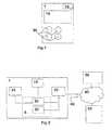
- FIG. 2shows the transceiver according to the invention, connected to a mobile radio network
- FIG. 3shows a flowchart for the evaluation of a message parameter of a received message
- FIG. 4shows an example of signaling a message parameter.
- SMSShort message services
- GSM mobile radio networkgroup speciale mobile
- SMSoffers the possibility of message concatenation, i.e. the total amount of the text to be sent is divided into a number of short messages.
- An appropriately specified mechanismprovides for proper reassembly in the receiver.
- SMSShort Message Service
- unified messaginga platform that combines fax, email, voicemail, etc. and offers a uniform access (usually via the Internet) to the data of these currently separate services.
- SMS messagesconstitute an important component, functioning as a notification for newly received data.
- the inventionwill be described below by way of example in conjunction with SMS and SMS messages; however, it is not limited to being used exclusively with messages using the SMS standard.
- the advantage of the short message serviceis that a message reaches the receiver directly or, if the mobile terminal is not available, is temporarily stored and is automatically resent when the mobile terminal once again becomes available. For this reason, in addition to the transmission of normal text messages, this service is also used for notification as a component of other services.
- Voicemailis one instance, as a rule a central one, in the mobile radio network of a network provider, which—similar to local answering machines connected to a user's telephone jack in the fixed network—offers the possibility of storing voice messages for a user of the mobile radio network. This can be the case if the person being called is unavailable at the time of the call, for example due to a dead zone in the coverage area of the mobile radio network or because the person being called does not have his mobile telephone turned on. If a caller then leaves a message in a voicemail box, then as a rule, the recipient is notified by means of an SMS text message as to the arrival and number of these new voice messages.
- the recipientwhen an SMS message is received, the recipient is notified by means of a corresponding indication on the display unit of the telephone.
- many mobile telephoneshave the feature of a display unit, which automatically switches off or switches into a power-saving mode if unused for a certain amount of time by the user, to reduce the energy consumption of the mobile telephone in order to increase battery life.
- the displayis reactivated, for example, by pressing the keypad of the mobile telephone. This means that the display device is switched off most of the time because most users do not use their mobile telephones actively for long periods.
- One feature of the inventionis that newly received messages can also be displayed in a transceiver, in particular a mobile telephone, independently of the display unit. This permits the immediate recognition of newly received messages even when a possible acoustic signal cannot be heard.
- FIG. 1schematically depicts a transceiver 1 according to the invention.
- the transceiver 1is provided in the form of a mobile telephone, cell phone, etc., and according to the invention, particularly functions in accordance with a standard for wireless communication, for example GSM, UMTS, or the like.
- the transceiver 1includes the display unit 16 , which is also referred to as the display 16 .
- the transceiver 1also includes a message indicator 15 and actuating elements 35 , for example buttons or the like.
- the message indicator 15is provided in the form of an LED (light emitting diode) and will therefore also be referred to below as the LED 15 .
- the LED 15is in particular embodied as a multicolor LED 15 , i.e. the message indicator 15 can display several colors. This potentially broadens the data content of a signal that can be conveyed to the user by means of the message indicator 15 .
- the LED 15is embodied, for example, as a dual-color LED 15 .
- the actuating elements 35are also referred to below as an input device 35 .
- the display unit 16can assume various operating states, at least one switched-on or activated operating state, and one switched-off operating state or an operating state with reduced activation (e.g. power-saving mode).
- FIG. 2shows the transceiver 1 connected to a mobile radio network 40 .
- the transceiver 1is connected to the mobile radio network 40 by means of an air interface 45 .
- a device 50is also connected to the mobile radio network 40 in a wireless fashion or via wires; the device 50 provides supplemental services in the mobile radio network 40 , for example a voicemail service.
- a communication terminal 60is also connected to the mobile radio network 40 , as a rule by means of a wireless interface that is not shown in detail.
- the mobile radio network 40particularly functions in accordance with a standard for wireless communication, for example GSM, UMTS, or the like.
- the transceiver 1includes, as a means for evaluating message parameters, an evaluation unit 20 , which is connected to the input device 35 , a send/receive device 10 , and the display unit 16 .
- the transceiver 1has a memory a 30 for storing data, for example short messages, which is connected to the send/receive device 10 .
- the memory 30is contained as a rule in an identification module, for example the SIM module (subscriber identification module). If the SIM module (subscriber identification module) is included, then it is possible to combine the memory 30 and the evaluation unit 20 onto one SIM module 5 . This possibility is indicated in FIG. 2 by the fact that the dashed line of the SIM module 5 encompasses the evaluation unit 20 and the memory 30 .
- SIM modulesubscriber identification module
- SIM application toolkitSIM application toolkit
- the send/receive device 10receives a short message from a mobile radio network 40 by means of the air interface 45 , for example from the telecommunication terminal 60 , from a supplementary service operated in the mobile radio network 40 , or a device 50 required for this supplementary service.
- the short messageis processed in the transceiver 1 , i.e. is displayed on the display unit 16 —if this is in a switched-on operating state—and is stored in the memory 30 .
- the messageis sent to the evaluation unit 20 , which in the simplest case registers the receipt of the message and displays or signals its arrival by means of the message indicator 15 .
- the input device 35can be used to input data for controlling the evaluation unit 20 and configuring it so that the display unit 16 and/or the message indicator 15 , for example, only display(s) selected short messages or so that different messages are displayed in different ways.
- One selection criterionfor example, is the telephone number of the sender, the type of message, the number of received messages, and/or whether the user has already accessed the message, i.e. whether the user has already listened to the message.
- the evaluation unit 20functions using the sender's telephone number as a selection criterion.
- the usercan use the input device 35 to configure the evaluation unit 20 in such a way that on the one hand, upon receipt of a short message that has been sent by the telecommunication terminal 60 , which is associated with a particular telephone number—for example the number “0172/4999008”, the message indicator 15 emits a signal, e.g. blinks, with a first color, and on the other hand, upon receipt of a short message as a notification regarding the receipt of a voice message in a voicemail box, the message indicator 15 emits a signal, e.g. blinks, with a second color.
- the signalwhich is embodied, for example, as a blink sequence, conveys information regarding the number of messages received, or regarding other message parameters. This is possible because it indicates the arrival or presence of for example three (e.g. unplayed) messages in the device SO that is embodied for example as a voicemail box, when the message indicator 15 blinks three times in rapid succession in one of its possible colors.
- FIG. 3shows a flowchart.
- a short messageis received and at a second program point 110 , it is stored, particularly in the memory 30 .
- the received short messageis evaluated in accordance with one or more message parameters; in the exemplary embodiment, the telephone number of the sender of the message has been selected as a message parameter.
- the example under considerationincludes the following cases by way of example: a first case labeled with the reference numeral 201 , which exists when a message has been received from the telecommunication terminal 60 that is associated, for example, with the telephone number “0172/4999008”; a second case labeled with the reference numeral 204 , which corresponds to the arrival of a message from the device 50 , i.e. for example a voicemail box; a third case labeled with the reference numeral 208 , which encompasses all other situations.
- a first counternot shown
- the new stateis displayed by the blinking of the LED 15 in the first color.
- a second counterlikewise not shown, is incremented and at a seventh program point 280 , the new state is displayed by the blinking of the LED 15 in the second, e.g. other, color. If it is determined at the third program point 200 that the third case 208 applies, then no further action occurs.
- the evaluation in the evaluation unit 20is not limited to the telephone number of the sender. It can also relate to the text of the message or short message, the type of message, the number of messages received, or the like. For example, the presence or lack of the words “mailbox” or “e-mail” are used as selection criteria in order to determine the type of message. Likewise, elements of the SMS header, i.e. the top part of an SMS message, or of the SMS user data header can be used for the selection. In addition, it is also appropriate here to use special user-defined selection criteria, which make it possible to recognize particular notifications, i.e.
- FIG. 4shows an example of a message indicator 15 signal.
- a blink sequenceis shown, which is characterized by the fact that blinks occur three times with a first chronological spacing 320 .
- a single blinkis produced by the fact that the intensity 310 of the output signal of the message indicator 15 changes for example twice, i.e. the intensity 310 is adjusted from a first value to a second value and—after a certain waiting period—is adjusted back to the first value in order to remain there for a certain additional waiting period.
- the first chronological spacing 320corresponds to the time interval beginning with the intensity change from the first value of the intensity 310 to the second value of the intensity 310 and extending to the end of the additional waiting period after the readjustment of the intensity 310 of the output signal back to the first value.
- the above-described sequence of three blinksi.e. a total of six changes in the intensity of the output signal—the number of intensity changes corresponds to twice the number of received messages—gives an example of how it is possible according to the invention, to signal the receipt of three new messages.
- FIG. 4shows two such blink sequences; a second chronological spacing 330 is provided between the blink sequences.
- the second chronological spacing 330is provided so that the user can differentiate or distinguish between the blink sequences, for example by virtue of the fact that the second chronological spacing 330 is greater than the first chronological spacing.
- Other possibilities for embodying the message indicator 15 signalare achieved by virtue of the fact that the intensity of the output signal of the message indicator 15 does not change in a binary fashion as shown in FIG. 4 —i.e. there are only two states—, but rather the signal can also be provided so that there are more than two discrete values for the intensity 310 and so that the intensity change of the output signal from one of these discrete values to another of these discrete values sends the user information about a received message.
- another embodimentincludes the provision of using the message indicator 15 to send the user other data, in particular operating data, in addition to the data regarding the status of the message reception or the arrival of a message.
- operating dataare understood in particular to include the charge state of the battery, not shown, or accumulator, not shown, (battery status), data regarding the availability of the mobile radio network 40 , or data regarding whether or not the transceiver 1 is currently logged onto the mobile radio network 40 . It was already possible before now to convey such operating data to the user by means of an additional signal particularly by using light emitting diodes.
- transceiversFor information of a content-related nature about messages, such as the number, type, or even the sender of messages among others, though, transceivers previously always used the display unit, which resulted in the above-explained disadvantages, particularly the higher power consumption and the complex operation of such transceivers.
- the additional signaling of operating data and the signaling of content-related informationi.e. regarding the receipt of messages for example, to the user both separately, i.e. using the message indicator 15 and an additional message indicator not shown here—for example with two different light emitting diodes—and jointly, i.e. using the message indicator 15 both for signaling the operating data and for signaling the status of the message reception.
- the operating dataare signaled exclusively by means of a third color, while the content-related information is only signaled by means of the first and second color.
- a transceiver 1is equipped, for example, in such a way that the LED 15 blinks with a relatively low frequency in a red color if the transceiver 1 is no longer receiving the regular signals of the mobile radio network 40 or is only receiving them poorly, e.g. in the case of a dead zone in the coverage of the mobile radio network 40 .
- the LED 15if the battery is almost dead, then the LED 15 blinks with a high frequency and likewise in the red color, independent of whether the transceiver 1 has reception or not.
- the LED 15blinks with a relatively low frequency in the green color.
- the usertherefore can always see whether the transceiver 1 has reception and whether the battery urgently needs to be charged—and this, independent of whether the display unit is switched on, switched off, or in a power-saving mode.
- the inventionincludes the provision that the light emitting diode blinks in a blue color, for example.
- the inventionnot to provide an additional color of the LED 15 for signaling the receipt of a message, but merely to provide a different blink signal than the low frequency blinking in the green color, which occurs in the exemplary embodiment under consideration when the transceiver 1 both has contact with the mobile radio network and also has sufficient energy reserves. This assures that the user always knows whether or not the transceiver 1 is logged onto the mobile radio network 40 . For example, if there are now three new messages, then the LED 15 blinks three times with a chronological spacing of the blink signal, which corresponds to the first spacing 320 .
- an average blink frequency between the two low frequency blinksis set to signal a proper network connection on the one hand and that of the high frequency blinks is set to signal an insufficient charge of the battery on the other hand.
- the LED 15executes a long pause before it blinks again three times in the average blink frequency.
- the duration of the long pausehere should be at least as long as the chronological spacings of the blink signal of the low frequency blinking.
Landscapes
- Engineering & Computer Science (AREA)
- Signal Processing (AREA)
- Computer Networks & Wireless Communication (AREA)
- Human Computer Interaction (AREA)
- Business, Economics & Management (AREA)
- General Business, Economics & Management (AREA)
- Telephone Function (AREA)
- Mobile Radio Communication Systems (AREA)
- Telephonic Communication Services (AREA)
Abstract
Description
Claims (9)
Priority Applications (2)
| Application Number | Priority Date | Filing Date | Title |
|---|---|---|---|
| US12/696,904US8923821B2 (en) | 2000-09-02 | 2010-01-29 | Transceiver with message notification |
| US14/558,114US20150156305A1 (en) | 2000-09-02 | 2014-12-02 | Transceiver with message notification |
Applications Claiming Priority (6)
| Application Number | Priority Date | Filing Date | Title |
|---|---|---|---|
| DE10043284ADE10043284C1 (en) | 2000-09-02 | 2000-09-02 | Radio device for GSM mobile radio system has information indicator providing information status indication independent of operative state of display device |
| DE10043284 | 2000-09-02 | ||
| DE10043284.0-35 | 2000-09-02 | ||
| PCT/DE2001/003304WO2002019676A1 (en) | 2000-09-02 | 2001-08-30 | Radio communication device |
| US10/363,625US7684789B2 (en) | 2000-09-02 | 2001-08-30 | Transceiver with message notification |
| US12/696,904US8923821B2 (en) | 2000-09-02 | 2010-01-29 | Transceiver with message notification |
Related Parent Applications (3)
| Application Number | Title | Priority Date | Filing Date |
|---|---|---|---|
| US10/363,625ContinuationUS7684789B2 (en) | 2000-09-02 | 2001-08-30 | Transceiver with message notification |
| PCT/DE2001/003304ContinuationWO2002019676A1 (en) | 2000-09-02 | 2001-08-30 | Radio communication device |
| US10363625Continuation | 2001-08-30 |
Related Child Applications (1)
| Application Number | Title | Priority Date | Filing Date |
|---|---|---|---|
| US14/558,114ContinuationUS20150156305A1 (en) | 2000-09-02 | 2014-12-02 | Transceiver with message notification |
Publications (2)
| Publication Number | Publication Date |
|---|---|
| US20100197280A1 US20100197280A1 (en) | 2010-08-05 |
| US8923821B2true US8923821B2 (en) | 2014-12-30 |
Family
ID=7654755
Family Applications (3)
| Application Number | Title | Priority Date | Filing Date |
|---|---|---|---|
| US10/363,625Expired - Fee RelatedUS7684789B2 (en) | 2000-09-02 | 2001-08-30 | Transceiver with message notification |
| US12/696,904Expired - Fee RelatedUS8923821B2 (en) | 2000-09-02 | 2010-01-29 | Transceiver with message notification |
| US14/558,114AbandonedUS20150156305A1 (en) | 2000-09-02 | 2014-12-02 | Transceiver with message notification |
Family Applications Before (1)
| Application Number | Title | Priority Date | Filing Date |
|---|---|---|---|
| US10/363,625Expired - Fee RelatedUS7684789B2 (en) | 2000-09-02 | 2001-08-30 | Transceiver with message notification |
Family Applications After (1)
| Application Number | Title | Priority Date | Filing Date |
|---|---|---|---|
| US14/558,114AbandonedUS20150156305A1 (en) | 2000-09-02 | 2014-12-02 | Transceiver with message notification |
Country Status (5)
| Country | Link |
|---|---|
| US (3) | US7684789B2 (en) |
| EP (2) | EP1316199B1 (en) |
| JP (2) | JP2004507982A (en) |
| DE (3) | DE10043284C1 (en) |
| WO (1) | WO2002019676A1 (en) |
Families Citing this family (15)
| Publication number | Priority date | Publication date | Assignee | Title |
|---|---|---|---|---|
| DE10043284C1 (en) | 2000-09-02 | 2002-02-07 | Bosch Gmbh Robert | Radio device for GSM mobile radio system has information indicator providing information status indication independent of operative state of display device |
| DE10245456B4 (en)* | 2002-09-27 | 2005-07-28 | Gkikas, Karolos, Glyfada | Method, system and device for sending and receiving messages, in particular multimedia and / or text messages and / or files, via a landline network |
| US7528974B2 (en)* | 2003-02-28 | 2009-05-05 | Electronics For Imaging, Inc. | Methods and apparatus for providing universal print services and asynchronous message services |
| US7391164B2 (en)* | 2004-09-15 | 2008-06-24 | Research In Motion Limited | Visual notification methods for candy-bar type cellphones |
| DE102005023962A1 (en)* | 2005-05-20 | 2006-11-23 | Vodafone Holding Gmbh | Method for operating in telecommunication network e.g. mobile telephone network involves number of information available for more extensive use is recorded and is displayed on display device of terminal device |
| US8396456B2 (en)* | 2005-06-28 | 2013-03-12 | Avaya Integrated Cabinet Solutions Inc. | Visual voicemail management |
| KR100791117B1 (en)* | 2006-11-09 | 2008-01-02 | 주식회사 서비전자 | RF communication device control device and method |
| KR101633329B1 (en)* | 2009-08-19 | 2016-06-24 | 엘지전자 주식회사 | Mobile terminal and method for controlling therof |
| KR101913176B1 (en)* | 2011-12-29 | 2018-11-01 | 삼성전자주식회사 | Method and apparatus for controlling a power of television device |
| US9173045B2 (en) | 2012-02-21 | 2015-10-27 | Imation Corp. | Headphone response optimization |
| US9219957B2 (en) | 2012-03-30 | 2015-12-22 | Imation Corp. | Sound pressure level limiting |
| SG11201503588VA (en) | 2014-06-09 | 2016-01-28 | Razer Asia Pacific Pte Ltd | Radio communication devices and methods for controlling a radio communictaion device |
| CN105284138B (en) | 2014-06-09 | 2019-08-06 | 雷蛇(亚太)私人有限公司 | Radio communications system and radio communication method |
| AU2014396908B2 (en)* | 2014-06-09 | 2017-08-10 | Razer (Asia-Pacific) Pte. Ltd. | Radio communication devices and methods for controlling a radio communication device |
| US11113933B1 (en)* | 2020-02-28 | 2021-09-07 | Therm-Omega-Tech, Inc. | Visual indication system for feedback controller |
Citations (35)
| Publication number | Priority date | Publication date | Assignee | Title |
|---|---|---|---|---|
| US4633041A (en) | 1984-04-09 | 1986-12-30 | At&T Information Systems Inc. | Station set directory assistance arrangement |
| US4649563A (en) | 1984-04-02 | 1987-03-10 | R L Associates | Method of and means for accessing computerized data bases utilizing a touch-tone telephone instrument |
| US4975694A (en) | 1989-03-14 | 1990-12-04 | Motorola, Inc. | Paging receiver with variable color indicators |
| EP0457077A2 (en) | 1990-05-16 | 1991-11-21 | Siemens Rolm Communications Inc. (a Delaware corp.) | Accessing alphanumeric information using a numeric keypad |
| EP0494525A2 (en) | 1991-01-11 | 1992-07-15 | Nokia Mobile Phones (U.K.) Limited | Telephone apparatus with calling line identification |
| EP0633684A2 (en) | 1993-07-08 | 1995-01-11 | US WEST Technologies, Inc. | Mobile telephone user interface including fixed and dynamic function keys and method of using same |
| DE4332758A1 (en) | 1993-09-25 | 1995-03-30 | Sel Alcatel Ag | Radio terminal for sending and receiving short messages |
| US5550754A (en) | 1994-05-13 | 1996-08-27 | Videoptic Research | Teleconferencing camcorder |
| US5566226A (en)* | 1994-05-31 | 1996-10-15 | Nec Corporation | Portable telephone apparatus which can be connected to an external apparatus without using an adapter |
| US5570025A (en) | 1994-11-16 | 1996-10-29 | Lauritsen; Dan D. | Annunciator and battery supply measurement system for cellular telephones |
| US5737394A (en) | 1996-02-06 | 1998-04-07 | Sony Corporation | Portable telephone apparatus having a plurality of selectable functions activated by the use of dedicated and/or soft keys |
| JPH10164664A (en) | 1996-11-28 | 1998-06-19 | Kyocera Corp | Mobile communication equipment |
| GB2326051A (en) | 1997-06-05 | 1998-12-09 | Motorola Inc | Mobile phone having multiple displays |
| DE19724995A1 (en) | 1997-06-13 | 1998-12-24 | Marion Wasenitz | Signal generator for call arriving to network call responder |
| WO1999000962A1 (en) | 1997-06-25 | 1999-01-07 | Siemens Aktiengesellschaft | Mobile telephone with an audio unit |
| US5881377A (en)* | 1996-08-29 | 1999-03-09 | Motorola, Inc. | Communication device and display blanking control method therefor |
| EP0936793A1 (en) | 1997-12-02 | 1999-08-18 | Nokia Mobile Phones Ltd. | A method and an arrangement for conserving power in a mobile station |
| US5946636A (en) | 1996-10-02 | 1999-08-31 | Ericsson Inc. | Quick-recognition visual notification system for use in radiotelephones |
| US6018232A (en) | 1996-02-27 | 2000-01-25 | Fujitsu Limited | Method of operating battery powered computing device with radio transmitter |
| US6078612A (en)* | 1997-05-16 | 2000-06-20 | Itt Manufacturing Enterprises, Inc. | Radio architecture for an advanced digital radio in a digital communication system |
| DE19857902A1 (en) | 1998-12-15 | 2000-06-29 | Deutsche Telekom Mobil | Method and device for transmitting short messages in telecommunication networks |
| US6088516A (en) | 1995-03-30 | 2000-07-11 | Kreisel; Glenn M. | Method for cloning a source application with assignment of unique identifier to clone application |
| US6104923A (en) | 1997-10-03 | 2000-08-15 | Karen Kite | Remote operational screener |
| US6119014A (en)* | 1998-04-01 | 2000-09-12 | Ericsson Inc. | System and method for displaying short messages depending upon location, priority, and user-defined indicators |
| US6209011B1 (en) | 1997-05-08 | 2001-03-27 | Microsoft Corporation | Handheld computing device with external notification system |
| US6295458B1 (en)* | 1998-05-29 | 2001-09-25 | Sharp Kabushiki Kaisha | Device for automatically generating an addressee number to which a short message is to be transmitted |
| US6330461B1 (en)* | 1997-06-06 | 2001-12-11 | Telefonaktiebolaget Lm Ericsson (Publ) | Mobile telephone apparatus |
| DE10043284C1 (en) | 2000-09-02 | 2002-02-07 | Bosch Gmbh Robert | Radio device for GSM mobile radio system has information indicator providing information status indication independent of operative state of display device |
| US6377821B2 (en)* | 1997-10-09 | 2002-04-23 | Avaya Technology Corp. | Display-based interface for a communication device |
| US6405060B1 (en)* | 1995-07-19 | 2002-06-11 | Cirrus Logic, Inc. | User interface with improved data entry features for telephone system |
| US6438390B1 (en) | 1999-05-06 | 2002-08-20 | Motorola, Inc. | Plural status indication control method suitable for use in a communication device |
| US6473628B1 (en)* | 1997-10-31 | 2002-10-29 | Sanyo Electric Co., Ltd. | Telephone set |
| US6720863B2 (en)* | 2001-08-16 | 2004-04-13 | Wildseed Ltd. | Mobile electronic communication device with lights to indicate received messages |
| US6751484B1 (en)* | 1999-07-08 | 2004-06-15 | Telefonaktiebolaget Lm Ericsson | Portable communication apparatus having visual indicator means and a method of providing visual status indication thereof |
| US7054626B2 (en)* | 1995-12-11 | 2006-05-30 | Openwave Systems Inc. | Method and architecture for an interactive two-way data communication network |
Family Cites Families (14)
| Publication number | Priority date | Publication date | Assignee | Title |
|---|---|---|---|---|
| DE494525C (en) | 1930-03-24 | Aeg | Arrangement of the termination of multiple cables | |
| JPS63211949A (en)* | 1987-02-27 | 1988-09-05 | Toshiba Corp | telephone equipment |
| GB8809404D0 (en) | 1988-04-21 | 1988-05-25 | Wisepeak Ltd | Upholstered furniture |
| SE500239C2 (en)* | 1992-09-04 | 1994-05-09 | Allgon Ab | Antenna mount on glass pane |
| JP2647055B2 (en)* | 1995-05-17 | 1997-08-27 | 日本電気株式会社 | Wireless selective call receiver with display function |
| JPH08317046A (en)* | 1995-05-23 | 1996-11-29 | Nitsuko Corp | Automatic answering telephone set |
| JPH10126827A (en)* | 1996-10-18 | 1998-05-15 | Oki Tsushin Syst Kk | Radio call receiver |
| JPH10207796A (en)* | 1997-01-22 | 1998-08-07 | Casio Comput Co Ltd | How emails are processed |
| US5877695A (en)* | 1997-10-07 | 1999-03-02 | Ericsson, Inc. | Visual alarm for a communication module |
| JPH11187151A (en)* | 1997-12-24 | 1999-07-09 | Sharp Corp | Incoming call notification method and apparatus, and recording medium storing data and a program for executing the method |
| JP2000036985A (en)* | 1998-07-21 | 2000-02-02 | Toshiba Corp | Wireless portable terminal device |
| JP3462778B2 (en)* | 1999-02-10 | 2003-11-05 | 三洋電機株式会社 | Mobile phone equipment |
| JP2001217904A (en)* | 2000-02-03 | 2001-08-10 | Nec Saitama Ltd | Portable telephone provided with lighting function |
| US7706843B2 (en)* | 2002-09-19 | 2010-04-27 | Kyocera Wireless Corp. | Mobile handset including alert mechanism |
- 2000
- 2000-09-02DEDE10043284Apatent/DE10043284C1/ennot_activeExpired - Lifetime
- 2001
- 2001-08-30EPEP01971671Apatent/EP1316199B1/ennot_activeExpired - Lifetime
- 2001-08-30USUS10/363,625patent/US7684789B2/ennot_activeExpired - Fee Related
- 2001-08-30DEDE50108026Tpatent/DE50108026D1/ennot_activeExpired - Lifetime
- 2001-08-30DEDE50115257Tpatent/DE50115257D1/ennot_activeExpired - Lifetime
- 2001-08-30WOPCT/DE2001/003304patent/WO2002019676A1/enactiveIP Right Grant
- 2001-08-30EPEP05024181Apatent/EP1622348B1/ennot_activeExpired - Lifetime
- 2001-08-30JPJP2002523843Apatent/JP2004507982A/enactivePending
- 2010
- 2010-01-29USUS12/696,904patent/US8923821B2/ennot_activeExpired - Fee Related
- 2011
- 2011-09-15JPJP2011201981Apatent/JP5542758B2/ennot_activeExpired - Lifetime
- 2014
- 2014-12-02USUS14/558,114patent/US20150156305A1/ennot_activeAbandoned
Patent Citations (42)
| Publication number | Priority date | Publication date | Assignee | Title |
|---|---|---|---|---|
| US4649563A (en) | 1984-04-02 | 1987-03-10 | R L Associates | Method of and means for accessing computerized data bases utilizing a touch-tone telephone instrument |
| US4633041A (en) | 1984-04-09 | 1986-12-30 | At&T Information Systems Inc. | Station set directory assistance arrangement |
| US4975694A (en) | 1989-03-14 | 1990-12-04 | Motorola, Inc. | Paging receiver with variable color indicators |
| EP0457077A2 (en) | 1990-05-16 | 1991-11-21 | Siemens Rolm Communications Inc. (a Delaware corp.) | Accessing alphanumeric information using a numeric keypad |
| EP0494525A2 (en) | 1991-01-11 | 1992-07-15 | Nokia Mobile Phones (U.K.) Limited | Telephone apparatus with calling line identification |
| US5633912A (en)* | 1993-07-08 | 1997-05-27 | U S West Advanced Technologies, Inc. | Mobile telephone user interface including fixed and dynamic function keys and method of using same |
| EP0633684A2 (en) | 1993-07-08 | 1995-01-11 | US WEST Technologies, Inc. | Mobile telephone user interface including fixed and dynamic function keys and method of using same |
| DE4332758A1 (en) | 1993-09-25 | 1995-03-30 | Sel Alcatel Ag | Radio terminal for sending and receiving short messages |
| US5550754A (en) | 1994-05-13 | 1996-08-27 | Videoptic Research | Teleconferencing camcorder |
| US5566226A (en)* | 1994-05-31 | 1996-10-15 | Nec Corporation | Portable telephone apparatus which can be connected to an external apparatus without using an adapter |
| US5570025A (en) | 1994-11-16 | 1996-10-29 | Lauritsen; Dan D. | Annunciator and battery supply measurement system for cellular telephones |
| US6088516A (en) | 1995-03-30 | 2000-07-11 | Kreisel; Glenn M. | Method for cloning a source application with assignment of unique identifier to clone application |
| US6405060B1 (en)* | 1995-07-19 | 2002-06-11 | Cirrus Logic, Inc. | User interface with improved data entry features for telephone system |
| US7054626B2 (en)* | 1995-12-11 | 2006-05-30 | Openwave Systems Inc. | Method and architecture for an interactive two-way data communication network |
| US5737394A (en) | 1996-02-06 | 1998-04-07 | Sony Corporation | Portable telephone apparatus having a plurality of selectable functions activated by the use of dedicated and/or soft keys |
| US6018232A (en) | 1996-02-27 | 2000-01-25 | Fujitsu Limited | Method of operating battery powered computing device with radio transmitter |
| US6311282B1 (en) | 1996-02-27 | 2001-10-30 | Fujitsu Personal Systems, Inc. | Method and apparatus for computing device with status display |
| US5881377A (en)* | 1996-08-29 | 1999-03-09 | Motorola, Inc. | Communication device and display blanking control method therefor |
| US5946636A (en) | 1996-10-02 | 1999-08-31 | Ericsson Inc. | Quick-recognition visual notification system for use in radiotelephones |
| JPH10164664A (en) | 1996-11-28 | 1998-06-19 | Kyocera Corp | Mobile communication equipment |
| US6209011B1 (en) | 1997-05-08 | 2001-03-27 | Microsoft Corporation | Handheld computing device with external notification system |
| US6078612A (en)* | 1997-05-16 | 2000-06-20 | Itt Manufacturing Enterprises, Inc. | Radio architecture for an advanced digital radio in a digital communication system |
| GB2326051A (en) | 1997-06-05 | 1998-12-09 | Motorola Inc | Mobile phone having multiple displays |
| DE19823882A1 (en) | 1997-06-05 | 1998-12-10 | Motorola Inc | Message transmission device with multiple displays and method for its operation |
| US6304763B1 (en) | 1997-06-05 | 2001-10-16 | Motorola, Inc. | Communication device having multiple displays and method of operating the same |
| US6125286A (en) | 1997-06-05 | 2000-09-26 | Motorola, Inc. | Communication device having multiple displays and method of operating the same |
| US6330461B1 (en)* | 1997-06-06 | 2001-12-11 | Telefonaktiebolaget Lm Ericsson (Publ) | Mobile telephone apparatus |
| DE19724995A1 (en) | 1997-06-13 | 1998-12-24 | Marion Wasenitz | Signal generator for call arriving to network call responder |
| WO1999000962A1 (en) | 1997-06-25 | 1999-01-07 | Siemens Aktiengesellschaft | Mobile telephone with an audio unit |
| US6104923A (en) | 1997-10-03 | 2000-08-15 | Karen Kite | Remote operational screener |
| US6377821B2 (en)* | 1997-10-09 | 2002-04-23 | Avaya Technology Corp. | Display-based interface for a communication device |
| US6473628B1 (en)* | 1997-10-31 | 2002-10-29 | Sanyo Electric Co., Ltd. | Telephone set |
| EP0936793A1 (en) | 1997-12-02 | 1999-08-18 | Nokia Mobile Phones Ltd. | A method and an arrangement for conserving power in a mobile station |
| US6119014A (en)* | 1998-04-01 | 2000-09-12 | Ericsson Inc. | System and method for displaying short messages depending upon location, priority, and user-defined indicators |
| US6295458B1 (en)* | 1998-05-29 | 2001-09-25 | Sharp Kabushiki Kaisha | Device for automatically generating an addressee number to which a short message is to be transmitted |
| DE19857902A1 (en) | 1998-12-15 | 2000-06-29 | Deutsche Telekom Mobil | Method and device for transmitting short messages in telecommunication networks |
| US6438390B1 (en) | 1999-05-06 | 2002-08-20 | Motorola, Inc. | Plural status indication control method suitable for use in a communication device |
| US6751484B1 (en)* | 1999-07-08 | 2004-06-15 | Telefonaktiebolaget Lm Ericsson | Portable communication apparatus having visual indicator means and a method of providing visual status indication thereof |
| DE10043284C1 (en) | 2000-09-02 | 2002-02-07 | Bosch Gmbh Robert | Radio device for GSM mobile radio system has information indicator providing information status indication independent of operative state of display device |
| US20040033783A1 (en) | 2000-09-02 | 2004-02-19 | Martin Hans | Radio communication device |
| EP1316199B1 (en) | 2000-09-02 | 2005-11-09 | Robert Bosch Gmbh | Radio communication device |
| US6720863B2 (en)* | 2001-08-16 | 2004-04-13 | Wildseed Ltd. | Mobile electronic communication device with lights to indicate received messages |
Non-Patent Citations (4)
| Title |
|---|
| Nokia 9000i, "User's Manual," (1995-1997). |
| Nokia, "First GSM-based communicator product hits the market. Nokia Starts Sales of the Nokia 9000 Communicator," Press Release (1996). |
| Nokia, "Nokia 9000 Communicator, User's Manual," (1995). |
| Nokia, "Nokia introduces the new Nokia 9000i Communicator for GSM Markets," Press Release (1997). |
Also Published As
| Publication number | Publication date |
|---|---|
| EP1316199A1 (en) | 2003-06-04 |
| US20150156305A1 (en) | 2015-06-04 |
| JP2012016056A (en) | 2012-01-19 |
| US20100197280A1 (en) | 2010-08-05 |
| US20040033783A1 (en) | 2004-02-19 |
| WO2002019676A1 (en) | 2002-03-07 |
| JP5542758B2 (en) | 2014-07-09 |
| EP1622348A1 (en) | 2006-02-01 |
| EP1316199B1 (en) | 2005-11-09 |
| EP1622348B1 (en) | 2009-12-09 |
| DE10043284C1 (en) | 2002-02-07 |
| JP2004507982A (en) | 2004-03-11 |
| US7684789B2 (en) | 2010-03-23 |
| DE50108026D1 (en) | 2005-12-15 |
| DE50115257D1 (en) | 2010-01-21 |
Similar Documents
| Publication | Publication Date | Title |
|---|---|---|
| US8923821B2 (en) | Transceiver with message notification | |
| KR100690706B1 (en) | Short message management method of mobile communication terminal | |
| US11647110B2 (en) | Emergency notifications during scheduled silent modes on mobile phones | |
| US7103367B2 (en) | Network-based services for misplaced cellular mobile stations | |
| US6343329B1 (en) | Telecommunication system and method for exchanging information between an E-mail service and a subscriber in a telecommunication network | |
| KR100315338B1 (en) | Wireless telephone systems and cordless phones with multiple telephone numbers | |
| US6987443B2 (en) | Unified paging | |
| KR100743360B1 (en) | Non-receipt reason service service method using one-touch function | |
| KR100650452B1 (en) | How to control automatic response of mobile phone | |
| KR100719746B1 (en) | How to Send Unacceptable Messages to Recipients | |
| KR100798260B1 (en) | Non-receipt reason notification service method, terminal and system using one-touch function | |
| CN101730013A (en) | Method for realizing auto-answer of short message | |
| KR20060072777A (en) | Automated SSM service system and method for automatically sending message set by user to sender | |
| KR20090017010A (en) | Method of providing two-phone function of mobile communication terminal and mobile communication terminal having two-phone function | |
| KR20030034488A (en) | Method for state transmission of mobile information terminal | |
| KR100631682B1 (en) | Rejection of mobile communication terminal and its pseudo transmission method | |
| JP4358155B2 (en) | Mobile phone | |
| US20030053604A1 (en) | Method for announcing data entering a communication terminal device and communication terminal device | |
| KR100693271B1 (en) | Receive standby service method using Receive standby button | |
| KR20040085943A (en) | Method for controlling mobile communication terminal using sms | |
| KR100655967B1 (en) | Mobile communication terminal with automatic calling number switching function and method | |
| JPH09215056A (en) | Mobile communication control method | |
| KR20040051673A (en) | Method for automatic informing a call-drop reason of mobile communication system | |
| KR20030012631A (en) | Method for receiving short message of mobile telecommunication | |
| US20080102788A1 (en) | Method for reporting back a status of a mobile phone and related mobile phone |
Legal Events
| Date | Code | Title | Description |
|---|---|---|---|
| AS | Assignment | Owner name:IPCOM GMBH & CO. KG, GERMANY Free format text:ASSIGNMENT OF ASSIGNORS INTEREST;ASSIGNOR:ROBERT BOSCH GMBH;REEL/FRAME:024408/0730 Effective date:20071126 Owner name:ROBERT BOSCH GMBH, GERMANY Free format text:ASSIGNMENT OF ASSIGNORS INTEREST;ASSIGNORS:HANS, MARTIN;KOWALEWSKI, FRANK;LAUMEN, JOSEF;AND OTHERS;SIGNING DATES FROM 20030604 TO 20030828;REEL/FRAME:024408/0572 | |
| AS | Assignment | Owner name:KAROLS DEVELOPMENT CO LLC, NEW YORK Free format text:ASSIGNMENT OF ASSIGNORS INTEREST;ASSIGNOR:IPCOM GMBH & CO. KG, REPRESENTED BY ITS GENERAL PARTNER IPCOM BETEILIGUNGS GMBH;REEL/FRAME:030144/0541 Effective date:20120509 | |
| AS | Assignment | Owner name:KAROLS DEVELOPMENT CO LLC, NEW YORK Free format text:CORRECTIVE ASSIGNMENT TO CORRECT THE TYPE OF DOCUMENT PREVIOUSLY RECORDED ON REEL 030144, FRAME 0541. ASSIGNORS HEREBY CONFIRMS THE SUBMITTED DOCUMENT SHOULD HAVE BEEN SUBMITTED AS A SECURITY AGREEMENT NOT AN ASSIGNMENT;ASSIGNOR:IPCOM GMBH & CO. KG, REPRESENTED BY ITS GENERAL PARTNER IPCOM BETEILIGUNGS GMBH;REEL/FRAME:030407/0400 Effective date:20120509 | |
| AS | Assignment | Owner name:LANDESBANK BADEN-WUERTTEMBERG, GERMANY Free format text:SECURITY AGREEMENT;ASSIGNOR:IPCOM GMBH & CO. KG;REEL/FRAME:030571/0649 Effective date:20130607 | |
| STCF | Information on status: patent grant | Free format text:PATENTED CASE | |
| MAFP | Maintenance fee payment | Free format text:PAYMENT OF MAINTENANCE FEE, 4TH YEAR, LARGE ENTITY (ORIGINAL EVENT CODE: M1551) Year of fee payment:4 | |
| AS | Assignment | Owner name:IPCOM GMBH & CO. KG, GERMANY Free format text:CONFIRMATION OF RELEASE OF SECURITY INTEREST;ASSIGNOR:KAROLS DEVELOPMENT CO. LLC;REEL/FRAME:057186/0643 Effective date:20210811 | |
| FEPP | Fee payment procedure | Free format text:MAINTENANCE FEE REMINDER MAILED (ORIGINAL EVENT CODE: REM.); ENTITY STATUS OF PATENT OWNER: LARGE ENTITY | |
| LAPS | Lapse for failure to pay maintenance fees | Free format text:PATENT EXPIRED FOR FAILURE TO PAY MAINTENANCE FEES (ORIGINAL EVENT CODE: EXP.); ENTITY STATUS OF PATENT OWNER: LARGE ENTITY | |
| STCH | Information on status: patent discontinuation | Free format text:PATENT EXPIRED DUE TO NONPAYMENT OF MAINTENANCE FEES UNDER 37 CFR 1.362 | |
| FP | Lapsed due to failure to pay maintenance fee | Effective date:20221230 |