US8922972B2 - Integral module power conditioning system - Google Patents
Integral module power conditioning systemDownload PDFInfo
- Publication number
- US8922972B2 US8922972B2US13/208,607US201113208607AUS8922972B2US 8922972 B2US8922972 B2US 8922972B2US 201113208607 AUS201113208607 AUS 201113208607AUS 8922972 B2US8922972 B2US 8922972B2
- Authority
- US
- United States
- Prior art keywords
- solar module
- module support
- solar
- support frame
- plug
- Prior art date
- Legal status (The legal status is an assumption and is not a legal conclusion. Google has not performed a legal analysis and makes no representation as to the accuracy of the status listed.)
- Expired - Fee Related, expires
Links
Images


Classifications
- H—ELECTRICITY
- H10—SEMICONDUCTOR DEVICES; ELECTRIC SOLID-STATE DEVICES NOT OTHERWISE PROVIDED FOR
- H10F—INORGANIC SEMICONDUCTOR DEVICES SENSITIVE TO INFRARED RADIATION, LIGHT, ELECTROMAGNETIC RADIATION OF SHORTER WAVELENGTH OR CORPUSCULAR RADIATION
- H10F19/00—Integrated devices, or assemblies of multiple devices, comprising at least one photovoltaic cell covered by group H10F10/00, e.g. photovoltaic modules
- H01L31/042—
- F24J2/4647—
- F—MECHANICAL ENGINEERING; LIGHTING; HEATING; WEAPONS; BLASTING
- F24—HEATING; RANGES; VENTILATING
- F24S—SOLAR HEAT COLLECTORS; SOLAR HEAT SYSTEMS
- F24S80/00—Details, accessories or component parts of solar heat collectors not provided for in groups F24S10/00-F24S70/00
- F24S80/30—Arrangements for connecting the fluid circuits of solar collectors with each other or with other components, e.g. pipe connections; Fluid distributing means, e.g. headers
- H01L31/02013—
- H01L31/0424—
- H01L31/05—
- H01L31/0521—
- H01L31/058—
- H—ELECTRICITY
- H02—GENERATION; CONVERSION OR DISTRIBUTION OF ELECTRIC POWER
- H02S—GENERATION OF ELECTRIC POWER BY CONVERSION OF INFRARED RADIATION, VISIBLE LIGHT OR ULTRAVIOLET LIGHT, e.g. USING PHOTOVOLTAIC [PV] MODULES
- H02S30/00—Structural details of PV modules other than those related to light conversion
- H02S30/10—Frame structures
- H—ELECTRICITY
- H02—GENERATION; CONVERSION OR DISTRIBUTION OF ELECTRIC POWER
- H02S—GENERATION OF ELECTRIC POWER BY CONVERSION OF INFRARED RADIATION, VISIBLE LIGHT OR ULTRAVIOLET LIGHT, e.g. USING PHOTOVOLTAIC [PV] MODULES
- H02S40/00—Components or accessories in combination with PV modules, not provided for in groups H02S10/00 - H02S30/00
- H02S40/30—Electrical components
- H02S40/32—Electrical components comprising DC/AC inverter means associated with the PV module itself, e.g. AC modules
- H—ELECTRICITY
- H02—GENERATION; CONVERSION OR DISTRIBUTION OF ELECTRIC POWER
- H02S—GENERATION OF ELECTRIC POWER BY CONVERSION OF INFRARED RADIATION, VISIBLE LIGHT OR ULTRAVIOLET LIGHT, e.g. USING PHOTOVOLTAIC [PV] MODULES
- H02S40/00—Components or accessories in combination with PV modules, not provided for in groups H02S10/00 - H02S30/00
- H02S40/30—Electrical components
- H02S40/36—Electrical components characterised by special electrical interconnection means between two or more PV modules, e.g. electrical module-to-module connection
- H—ELECTRICITY
- H02—GENERATION; CONVERSION OR DISTRIBUTION OF ELECTRIC POWER
- H02S—GENERATION OF ELECTRIC POWER BY CONVERSION OF INFRARED RADIATION, VISIBLE LIGHT OR ULTRAVIOLET LIGHT, e.g. USING PHOTOVOLTAIC [PV] MODULES
- H02S40/00—Components or accessories in combination with PV modules, not provided for in groups H02S10/00 - H02S30/00
- H02S40/40—Thermal components
- H02S40/44—Means to utilise heat energy, e.g. hybrid systems producing warm water and electricity at the same time
- H—ELECTRICITY
- H10—SEMICONDUCTOR DEVICES; ELECTRIC SOLID-STATE DEVICES NOT OTHERWISE PROVIDED FOR
- H10F—INORGANIC SEMICONDUCTOR DEVICES SENSITIVE TO INFRARED RADIATION, LIGHT, ELECTROMAGNETIC RADIATION OF SHORTER WAVELENGTH OR CORPUSCULAR RADIATION
- H10F19/00—Integrated devices, or assemblies of multiple devices, comprising at least one photovoltaic cell covered by group H10F10/00, e.g. photovoltaic modules
- H10F19/90—Structures for connecting between photovoltaic cells, e.g. interconnections or insulating spacers
- H—ELECTRICITY
- H10—SEMICONDUCTOR DEVICES; ELECTRIC SOLID-STATE DEVICES NOT OTHERWISE PROVIDED FOR
- H10F—INORGANIC SEMICONDUCTOR DEVICES SENSITIVE TO INFRARED RADIATION, LIGHT, ELECTROMAGNETIC RADIATION OF SHORTER WAVELENGTH OR CORPUSCULAR RADIATION
- H10F77/00—Constructional details of devices covered by this subclass
- H10F77/60—Arrangements for cooling, heating, ventilating or compensating for temperature fluctuations
- H10F77/63—Arrangements for cooling directly associated or integrated with photovoltaic cells, e.g. heat sinks directly associated with the photovoltaic cells or integrated Peltier elements for active cooling
- H10F77/68—Arrangements for cooling directly associated or integrated with photovoltaic cells, e.g. heat sinks directly associated with the photovoltaic cells or integrated Peltier elements for active cooling using gaseous or liquid coolants, e.g. air flow ventilation or water circulation
- H—ELECTRICITY
- H10—SEMICONDUCTOR DEVICES; ELECTRIC SOLID-STATE DEVICES NOT OTHERWISE PROVIDED FOR
- H10F—INORGANIC SEMICONDUCTOR DEVICES SENSITIVE TO INFRARED RADIATION, LIGHT, ELECTROMAGNETIC RADIATION OF SHORTER WAVELENGTH OR CORPUSCULAR RADIATION
- H10F77/00—Constructional details of devices covered by this subclass
- H10F77/93—Interconnections
- H10F77/933—Interconnections for devices having potential barriers
- H10F77/935—Interconnections for devices having potential barriers for photovoltaic devices or modules
- H10F77/939—Output lead wires or elements
- Y—GENERAL TAGGING OF NEW TECHNOLOGICAL DEVELOPMENTS; GENERAL TAGGING OF CROSS-SECTIONAL TECHNOLOGIES SPANNING OVER SEVERAL SECTIONS OF THE IPC; TECHNICAL SUBJECTS COVERED BY FORMER USPC CROSS-REFERENCE ART COLLECTIONS [XRACs] AND DIGESTS
- Y02—TECHNOLOGIES OR APPLICATIONS FOR MITIGATION OR ADAPTATION AGAINST CLIMATE CHANGE
- Y02B—CLIMATE CHANGE MITIGATION TECHNOLOGIES RELATED TO BUILDINGS, e.g. HOUSING, HOUSE APPLIANCES OR RELATED END-USER APPLICATIONS
- Y02B10/00—Integration of renewable energy sources in buildings
- Y02B10/10—Photovoltaic [PV]
- Y02B10/12—
- Y—GENERAL TAGGING OF NEW TECHNOLOGICAL DEVELOPMENTS; GENERAL TAGGING OF CROSS-SECTIONAL TECHNOLOGIES SPANNING OVER SEVERAL SECTIONS OF THE IPC; TECHNICAL SUBJECTS COVERED BY FORMER USPC CROSS-REFERENCE ART COLLECTIONS [XRACs] AND DIGESTS
- Y02—TECHNOLOGIES OR APPLICATIONS FOR MITIGATION OR ADAPTATION AGAINST CLIMATE CHANGE
- Y02B—CLIMATE CHANGE MITIGATION TECHNOLOGIES RELATED TO BUILDINGS, e.g. HOUSING, HOUSE APPLIANCES OR RELATED END-USER APPLICATIONS
- Y02B10/00—Integration of renewable energy sources in buildings
- Y02B10/20—Solar thermal
- Y—GENERAL TAGGING OF NEW TECHNOLOGICAL DEVELOPMENTS; GENERAL TAGGING OF CROSS-SECTIONAL TECHNOLOGIES SPANNING OVER SEVERAL SECTIONS OF THE IPC; TECHNICAL SUBJECTS COVERED BY FORMER USPC CROSS-REFERENCE ART COLLECTIONS [XRACs] AND DIGESTS
- Y02—TECHNOLOGIES OR APPLICATIONS FOR MITIGATION OR ADAPTATION AGAINST CLIMATE CHANGE
- Y02B—CLIMATE CHANGE MITIGATION TECHNOLOGIES RELATED TO BUILDINGS, e.g. HOUSING, HOUSE APPLIANCES OR RELATED END-USER APPLICATIONS
- Y02B10/00—Integration of renewable energy sources in buildings
- Y02B10/70—Hybrid systems, e.g. uninterruptible or back-up power supplies integrating renewable energies
- Y—GENERAL TAGGING OF NEW TECHNOLOGICAL DEVELOPMENTS; GENERAL TAGGING OF CROSS-SECTIONAL TECHNOLOGIES SPANNING OVER SEVERAL SECTIONS OF THE IPC; TECHNICAL SUBJECTS COVERED BY FORMER USPC CROSS-REFERENCE ART COLLECTIONS [XRACs] AND DIGESTS
- Y02—TECHNOLOGIES OR APPLICATIONS FOR MITIGATION OR ADAPTATION AGAINST CLIMATE CHANGE
- Y02E—REDUCTION OF GREENHOUSE GAS [GHG] EMISSIONS, RELATED TO ENERGY GENERATION, TRANSMISSION OR DISTRIBUTION
- Y02E10/00—Energy generation through renewable energy sources
- Y02E10/40—Solar thermal energy, e.g. solar towers
- Y—GENERAL TAGGING OF NEW TECHNOLOGICAL DEVELOPMENTS; GENERAL TAGGING OF CROSS-SECTIONAL TECHNOLOGIES SPANNING OVER SEVERAL SECTIONS OF THE IPC; TECHNICAL SUBJECTS COVERED BY FORMER USPC CROSS-REFERENCE ART COLLECTIONS [XRACs] AND DIGESTS
- Y02—TECHNOLOGIES OR APPLICATIONS FOR MITIGATION OR ADAPTATION AGAINST CLIMATE CHANGE
- Y02E—REDUCTION OF GREENHOUSE GAS [GHG] EMISSIONS, RELATED TO ENERGY GENERATION, TRANSMISSION OR DISTRIBUTION
- Y02E10/00—Energy generation through renewable energy sources
- Y02E10/50—Photovoltaic [PV] energy
- Y—GENERAL TAGGING OF NEW TECHNOLOGICAL DEVELOPMENTS; GENERAL TAGGING OF CROSS-SECTIONAL TECHNOLOGIES SPANNING OVER SEVERAL SECTIONS OF THE IPC; TECHNICAL SUBJECTS COVERED BY FORMER USPC CROSS-REFERENCE ART COLLECTIONS [XRACs] AND DIGESTS
- Y02—TECHNOLOGIES OR APPLICATIONS FOR MITIGATION OR ADAPTATION AGAINST CLIMATE CHANGE
- Y02E—REDUCTION OF GREENHOUSE GAS [GHG] EMISSIONS, RELATED TO ENERGY GENERATION, TRANSMISSION OR DISTRIBUTION
- Y02E10/00—Energy generation through renewable energy sources
- Y02E10/60—Thermal-PV hybrids
Definitions
- PVphotovoltaic
- PV systemsNearly all electrical systems in the U.S. are grounded to mitigate the impacts of lightning, line surges, or unintentional contact with high voltage lines.
- Most PV systemsinclude modules with metal frames and metal mounting racks that are in exposed locations, e.g. rooftops, where they are subject to lightning strikes, or are located near high voltage transmission lines that in the event of high winds, etc., can come into contact with PV arrays.
- the modules in a typical PV arrayhave aluminum frames that are often anodized.
- the 2008 National Electrical Code (NEC)that has the same requirements as the draft 2010-NEC and governs installation of PV systems requires exposed metal surfaces be grounded.
- NECNational Electrical Code
- V600 volts
- AC moduleshave increasing importance in the solar power generation industry.
- DC to AC conversion that is local to each solar electric modulehas certain advantages for residential solar power generation systems. These advantages include without limitation, availability, high energy yield, simple interconnections, and the like.
- Most implementations of solar AC modulesinvolve the interconnection of a microinverter with a solar electric module.
- the microinverteris mounted onto the rail and DC-DC cabling is used to implement the connection in some installations.
- the AC connectionsare made in parallel through output cables on the microinverters.
- the microinverteris attached directly to the solar electric module in other installations by bolting the microinverter to the frame of the solar electric module; and the electrical interconnections are made in the same way.
- an apparatuscomprises a first solar module support frame comprising both a microinverter connector and a plurality of plug-and-play electrical connectors integrated therein, wherein the first solar module support frame is configured to receive both a solar electric module and a microinverter and to carry electrical power to the plug-and-play connectors.
- an apparatuscomprises:
- each solar module support framea plurality of plug-and-play electrical connectors integrated with each solar module support frame, wherein the plurality of solar module support frames are connected together in tandem via the plug-and-play electrical connectors to carry electrical power through a plurality of solar electric modules and corresponding microinverters connected together via the plurality of solar module support frame plug-and-play electrical connectors.
- an apparatuscomprises:
- each solar module support framecomprising both a microinverter connector and a plurality of plug-and-play electrical connectors integrated therein, wherein the plurality of solar module support frames are connected together in tandem via a corresponding plurality of plug-and-play electrical connectors to carry electrical power through a plurality of solar electric modules and corresponding microinverters mounted in the plurality of solar module support frames.
- FIG. 1illustrates a pair of solar module support frames with plug-and-play electrical connectors molded therein according to one embodiment
- FIG. 2illustrates the plug-and-play electrical connectors depicted in FIG. 1 in more detail
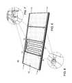
- FIG. 3illustrates the solar module support frames depicted in FIG. 1 with corresponding serpentine thermal coil assemblies and corresponding molded-in plumbing connectors according to one embodiment
- FIG. 4illustrates the molded-in plumbing connectors depicted in FIG. 3 in more detail
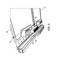
- FIG. 5illustrates a pair of solar module support frames with microinverter connectors molded therein according to one embodiment of the invention
- FIG. 6illustrates a plurality of solar modules installed in a string of solar module support frames interconnected via corresponding plug-and-play electrical connectors and corresponding molded-in plumbing connectors to accommodate electrical power and thermal transfer between the plurality of solar modules according to one embodiment
- FIG. 7illustrates the plug-and-play electrical connectors depicted in FIG. 6 in more detail.
- FIG. 8illustrates the molded-in plumbing connectors depicted in FIG. 6 in more detail.
- FIG. 1illustrates a pair of solar module support frames 10 , 12 with plug-and-play electrical connectors 14 , 16 molded therein according to one embodiment.
- FIG. 2depicts the electrical connectors 14 , 16 in more detail.
- Electrical connector 14can be seen to be a female electrical connector, while electrical connector 16 can be seen to be a male electrical connector.
- plug-and-play electrical connectors 14 , 16comprise quick-connect type electrical jacks that are molded into their respective solar module support frames 10 , 12 .
- Each solar module support frame 10 , 12can accommodate a solar electrical module or a solar thermal module, described in more detail herein.
- Plug-and-playis used to describe devices that work with a system as soon as they are connected. The user does not have to manually install drivers for the device or even tell the system that a new device has been added. Instead the system automatically recognizes the device, and begins to work with the newly connected device.
- Each solar module support frame 10 , 12further comprises a microinverter connector 18 molded therein to allow for electrical connections between a solar module inserted into the support frame and a respective microinverter.
- Microinverter connector 18is described in further detail herein.
- Each solar module support frame 10 , 12further comprises electrical wiring 20 molded therein to provide an electrical pathway between a corresponding microinverter and the respective support frame electrical connectors 14 , 16 .
- a non-electrified rack 21provides the main structure for assembling and interconnecting a plurality of solar module support frames 10 , 12 .
- any number of solar module support frames/solar modulescan be assembled into the non-electrified rack 21 , limited only by the physical size of the rack 21 .
- the solar module support frames and corresponding solar modulescan be connected in tandem to form a single dimensional array of solar modules; or the solar module support frames can be connected together with corresponding solar modules to form a two-dimensional array of solar modules.
- FIG. 3illustrates a pair of solar module support frames 10 , 12 with push-fit type quick connect plug-and-play mechanical plumbing connectors 24 , 26 molded therein according to one embodiment.
- FIG. 4illustrates the push-fit type plug-and-play mechanical plumbing connectors 22 , 24 depicted in FIG. 3 in more detail.
- Each solar module support frame 10 , 12can accommodate an electrical solar module or a thermal solar module, as stated herein.
- solar thermal modules and solar electric modulescan be mounted onto a common non-electrified rack 21 via a plurality of solar module frames 10 , 12 .
- the molded-in wiring 20 depicted in FIG. 1 and electrical connectors 14 , 16may reside in the top frame rail leg 26 to support electrical connections to a respective solar electric module, while the molded in plumbing connectors 22 , 24 may reside in the bottom frame rail leg 28 to support thermal fluid connections to a respective solar thermal module according to one embodiment.
- a set of serpentine cooling pipes 30 , 32 containing a thermal fluidmay be employed as a cooling brace to contact the backside of a respective solar electric module 31 to reduce its operating temperature.
- Heat transferred to the thermal fluid via the solar electric module 31may advantageously be transferred to a solar thermal module 33 downstream of the solar electric module 31 .
- a thermal heat transfer liquidpasses through the solar electric module serpentine cooling pipes 30 first so that the liquid is somewhat hot when it reaches the solar thermal module(s) 33 .
- FIG. 5illustrates a pair of solar module support frames 10 , 12 with a microinverter connector 18 molded therein according to one embodiment of the invention.
- This embodimentadvantageously integrates the requisite power electronics services with the supporting frame(s) 10 , 12 and respective power electronics connector(s) 14 , 16 , 18 to simplify the installation process.
- each supporting frame 10 , 12is a molded frame constructed from a plastic or composite material into which can also be included a pocket to receive a respective power microinverter 36 . Integrating the solar module support frame(s) 10 , 12 with quick connect electrical connectors 14 , 16 , quick connect plumbing connectors 22 , 24 and microinverter connectors 18 results in a desired plug-and-play architecture that is very cost effective to implement.
- FIG. 6illustrates an integral module power conditioning system 40 comprising a plurality of solar modules 42 installed in a string of solar module support frames interconnected via corresponding quick connect plug-and-play electrical connectors 12 , 14 and corresponding quick connect plug-and-play mechanical plumbing connectors 22 , 24 to accommodate electrical power and thermal transfer between the plurality of solar modules 42 according to one embodiment.
- Solar modules 42may include only solar electric modules, only solar thermal modules, or both solar electric modules and solar thermal modules, as stated herein.
- FIG. 7illustrates the molded-in quick connect plug-and-play electrical connectors 12 , 14 depicted in FIG. 6 in more detail
- FIG. 8illustrates the molded-in quick connect plug-and-play mechanical plumbing connectors 22 , 24 depicted in FIG. 6 in more detail.
- a microinverteris integrated into one or more solar module frames 10 , 12 that are constructed from metal.
- the framethen both operates as a heat spreader/sink and forms a case.
- a single jumper cablecan then be used to interconnect the DC input of the microinverter with the DC output of the module through a simple weather resistant connector.
- the plug-and-play electrical connectors integrated with the frame of the solar modulecomprise AC connectors housing up to four wires for a 240V AC system (120V, 120V, N, G).
- the solar electric modulesare electrically connected in parallel and routed directly to a residential load panel through a home run cable.
- an integral solar module power conditioning systemcomprises a first solar module support frame 10 comprising both a microinverter connector 18 and a plurality of plug-and-play electrical connectors 14 , 16 integrated therein, wherein the first solar module support frame 10 is configured to receive a solar electric module and to carry electrical power through a plurality of solar electric modules and corresponding microinverters connected together via the first solar module support frame 10 and at least one additional solar module support frame 12 connected in tandem with the first solar module support frame 10 via the plurality of integrated plug-and-play electrical connectors 14 , 16 .
- Embodiments consistent with the above descriptionmay provide a solar system architecture that reduces installation costs through integration of certain mechanical and electrical functions generally associated with individual components of such a system that include solar module(s), solar inverter(s) and solar module racking.
- a typical solar module systemincludes photovoltaic (PV) modules that are mechanically affixed to a mounting system and separately connected electrically in a wiring chain via wires that are integral to each module.
- the DC electric chain of series and/or parallel-connected PV modulesmay be routed to a DC-AC inverter.
- the embodiments described hereinemploy electrified solar module frames that include an AC or DC integral power bus and that supports integration with a solar module via a combined electrical and mechanical interconnect, eliminating the need for physical connections of wires.
- DC-AC or DC-DC power electronicssuch as power microinverter (s) 36 integrated with the individual modules advantageously provide local regulation and maximum peak power tracking (MPPT).
- MPPTpower microinverter
- Particular embodimentsadvantageously provide a solar module support frame that functions both as a structural element and inverter heat-sink enclosure through sharing of component structures.
- Some solar module frame embodiments described hereinfurther support both solar thermal modules and solar electric modules mounted into a common racking system.
- embodiments of an integral module power conditioning system described hereincomprise one or more solar module support frames and a plurality of quick connect plug-and-play mechanical plumbing connectors integrated with each solar module support frame, wherein each solar module support frame is configured to receive a solar module and to carry a heat transfer fluid to transfer heat to or from the solar module.
- Embodiments of the integral module power conditioning systemmay comprise one or more solar modules comprising integral DC voltage regulation, maximum peak power tracking and communications, an electrified solar module frame comprising an integral AC or DC power bus, and an architecture for electrically interfacing the solar modules to the electrified frame(s) installed within a corresponding rack system that does not require the physical connection of wires.
- microinvertercan be employed to provide regulation at the module level to address deficiencies that result from the mismatch of module performance across a string of modules.
- the benefits of microinvertersare however, accompanied by an increased cost, and in some cases the placement of the microinverters, e.g. attached to the backside of a module, limit the air-flow in an already difficult environment (i.e. high temperature) for inverters.
- the embodiments described hereinprovide an architecture that facilitates intelligent integration of all or a portion of the functionality of a microinverter within the construction of the module frame to reduce the sum total cost of the microinverter and module, to minimize heat build-up and operating temperature of the microinverter(s), to allow ease of access and repair of the microinverter/module and to simplify the interface to an electrified module frame.
- the foregoing advantagesmay be provided using the principles described herein without modifying the fundamental laminate structure of the solar module.
Landscapes
- Engineering & Computer Science (AREA)
- Life Sciences & Earth Sciences (AREA)
- Sustainable Development (AREA)
- Physics & Mathematics (AREA)
- Sustainable Energy (AREA)
- Thermal Sciences (AREA)
- Chemical & Material Sciences (AREA)
- Combustion & Propulsion (AREA)
- Mechanical Engineering (AREA)
- General Engineering & Computer Science (AREA)
- Photovoltaic Devices (AREA)
- Inverter Devices (AREA)
Abstract
Description
Claims (14)
Priority Applications (5)
| Application Number | Priority Date | Filing Date | Title |
|---|---|---|---|
| US13/208,607US8922972B2 (en) | 2011-08-12 | 2011-08-12 | Integral module power conditioning system |
| JP2012172424AJP2013042130A (en) | 2011-08-12 | 2012-08-03 | Integral module power conditioning system |
| EP12179639.5AEP2557602A3 (en) | 2011-08-12 | 2012-08-08 | Integral Module Power Conditioning System |
| AU2012211436AAU2012211436A1 (en) | 2011-08-12 | 2012-08-08 | Integral module power conditioning system |
| CN201210283712.XACN102957185B (en) | 2011-08-12 | 2012-08-10 | Integrate modular power regulation system |
Applications Claiming Priority (1)
| Application Number | Priority Date | Filing Date | Title |
|---|---|---|---|
| US13/208,607US8922972B2 (en) | 2011-08-12 | 2011-08-12 | Integral module power conditioning system |
Publications (2)
| Publication Number | Publication Date |
|---|---|
| US20130039028A1 US20130039028A1 (en) | 2013-02-14 |
| US8922972B2true US8922972B2 (en) | 2014-12-30 |
Family
ID=46829626
Family Applications (1)
| Application Number | Title | Priority Date | Filing Date |
|---|---|---|---|
| US13/208,607Expired - Fee RelatedUS8922972B2 (en) | 2011-08-12 | 2011-08-12 | Integral module power conditioning system |
Country Status (5)
| Country | Link |
|---|---|
| US (1) | US8922972B2 (en) |
| EP (1) | EP2557602A3 (en) |
| JP (1) | JP2013042130A (en) |
| CN (1) | CN102957185B (en) |
| AU (1) | AU2012211436A1 (en) |
Cited By (9)
| Publication number | Priority date | Publication date | Assignee | Title |
|---|---|---|---|---|
| US20130169056A1 (en)* | 2011-12-28 | 2013-07-04 | Miasole | Multi-module inverters and converters for building integrable photovoltaic modules |
| US20150109083A1 (en)* | 2013-10-19 | 2015-04-23 | Dean Solon | Modular photovoltaic power skid base system |
| WO2016195718A1 (en) | 2015-06-05 | 2016-12-08 | Lumeta, Llc | Apparatus and method for solar panel on-board wiring |
| US10050584B2 (en) | 2016-03-16 | 2018-08-14 | Hardware Labs Performance Systems, Inc. | Cooling apparatus for solar panels |
| US10164566B2 (en) | 2015-05-20 | 2018-12-25 | General Electric Company | Universal microinverter mounting bracket for a photovoltaic panel and associated method |
| US10371185B2 (en) | 2017-01-09 | 2019-08-06 | David Lynn | Magnetically-controlled connectors and methods of use |
| US10651786B2 (en) | 2018-01-08 | 2020-05-12 | David Lynn | Panel with magnetically-controlled connectors for attachment to a support member |
| US10971870B2 (en) | 2018-08-17 | 2021-04-06 | David Lynn | Connection interface for a panel and support structure |
| US20220060141A1 (en)* | 2020-08-24 | 2022-02-24 | Colin Felton | Labor Saving Solar Roofing Shingle |
Families Citing this family (50)
| Publication number | Priority date | Publication date | Assignee | Title |
|---|---|---|---|---|
| US10693415B2 (en) | 2007-12-05 | 2020-06-23 | Solaredge Technologies Ltd. | Testing of a photovoltaic panel |
| US11881814B2 (en) | 2005-12-05 | 2024-01-23 | Solaredge Technologies Ltd. | Testing of a photovoltaic panel |
| US11309832B2 (en) | 2006-12-06 | 2022-04-19 | Solaredge Technologies Ltd. | Distributed power harvesting systems using DC power sources |
| US8319483B2 (en) | 2007-08-06 | 2012-11-27 | Solaredge Technologies Ltd. | Digital average input current control in power converter |
| US8963369B2 (en) | 2007-12-04 | 2015-02-24 | Solaredge Technologies Ltd. | Distributed power harvesting systems using DC power sources |
| US11569659B2 (en) | 2006-12-06 | 2023-01-31 | Solaredge Technologies Ltd. | Distributed power harvesting systems using DC power sources |
| US9088178B2 (en) | 2006-12-06 | 2015-07-21 | Solaredge Technologies Ltd | Distributed power harvesting systems using DC power sources |
| US12316274B2 (en) | 2006-12-06 | 2025-05-27 | Solaredge Technologies Ltd. | Pairing of components in a direct current distributed power generation system |
| US11888387B2 (en) | 2006-12-06 | 2024-01-30 | Solaredge Technologies Ltd. | Safety mechanisms, wake up and shutdown methods in distributed power installations |
| US8013472B2 (en) | 2006-12-06 | 2011-09-06 | Solaredge, Ltd. | Method for distributed power harvesting using DC power sources |
| US11687112B2 (en) | 2006-12-06 | 2023-06-27 | Solaredge Technologies Ltd. | Distributed power harvesting systems using DC power sources |
| US8618692B2 (en) | 2007-12-04 | 2013-12-31 | Solaredge Technologies Ltd. | Distributed power system using direct current power sources |
| US11855231B2 (en) | 2006-12-06 | 2023-12-26 | Solaredge Technologies Ltd. | Distributed power harvesting systems using DC power sources |
| US8816535B2 (en) | 2007-10-10 | 2014-08-26 | Solaredge Technologies, Ltd. | System and method for protection during inverter shutdown in distributed power installations |
| US8473250B2 (en) | 2006-12-06 | 2013-06-25 | Solaredge, Ltd. | Monitoring of distributed power harvesting systems using DC power sources |
| US11735910B2 (en) | 2006-12-06 | 2023-08-22 | Solaredge Technologies Ltd. | Distributed power system using direct current power sources |
| US8319471B2 (en) | 2006-12-06 | 2012-11-27 | Solaredge, Ltd. | Battery power delivery module |
| US8947194B2 (en) | 2009-05-26 | 2015-02-03 | Solaredge Technologies Ltd. | Theft detection and prevention in a power generation system |
| US8384243B2 (en) | 2007-12-04 | 2013-02-26 | Solaredge Technologies Ltd. | Distributed power harvesting systems using DC power sources |
| WO2009072076A2 (en) | 2007-12-05 | 2009-06-11 | Solaredge Technologies Ltd. | Current sensing on a mosfet |
| US11264947B2 (en) | 2007-12-05 | 2022-03-01 | Solaredge Technologies Ltd. | Testing of a photovoltaic panel |
| CN105244905B (en) | 2007-12-05 | 2019-05-21 | 太阳能安吉有限公司 | Release mechanism in distributed power device is waken up and method for closing |
| EP2294669B8 (en) | 2008-05-05 | 2016-12-07 | Solaredge Technologies Ltd. | Direct current power combiner |
| US12418177B2 (en) | 2009-10-24 | 2025-09-16 | Solaredge Technologies Ltd. | Distributed power system using direct current power sources |
| GB2485527B (en) | 2010-11-09 | 2012-12-19 | Solaredge Technologies Ltd | Arc detection and prevention in a power generation system |
| US10673229B2 (en) | 2010-11-09 | 2020-06-02 | Solaredge Technologies Ltd. | Arc detection and prevention in a power generation system |
| GB2483317B (en) | 2011-01-12 | 2012-08-22 | Solaredge Technologies Ltd | Serially connected inverters |
| US8570005B2 (en) | 2011-09-12 | 2013-10-29 | Solaredge Technologies Ltd. | Direct current link circuit |
| GB2498365A (en) | 2012-01-11 | 2013-07-17 | Solaredge Technologies Ltd | Photovoltaic module |
| US9853565B2 (en) | 2012-01-30 | 2017-12-26 | Solaredge Technologies Ltd. | Maximized power in a photovoltaic distributed power system |
| GB2498791A (en) | 2012-01-30 | 2013-07-31 | Solaredge Technologies Ltd | Photovoltaic panel circuitry |
| US10115841B2 (en)* | 2012-06-04 | 2018-10-30 | Solaredge Technologies Ltd. | Integrated photovoltaic panel circuitry |
| WO2014118840A1 (en)* | 2013-01-29 | 2014-08-07 | 三洋電機株式会社 | Solar cell module |
| US9548619B2 (en) | 2013-03-14 | 2017-01-17 | Solaredge Technologies Ltd. | Method and apparatus for storing and depleting energy |
| EP3506370B1 (en) | 2013-03-15 | 2023-12-20 | Solaredge Technologies Ltd. | Bypass mechanism |
| ITMI20130483A1 (en)* | 2013-03-29 | 2014-09-30 | Comes Metalmeccanica S R L | INTEGRATED PHOTOVOLTAIC SYSTEM AND ITS IMPLEMENTATION METHOD |
| FR3004288A1 (en)* | 2013-04-04 | 2014-10-10 | Bc Partners | COOLING AUTO SOLAR PANEL |
| US20150028684A1 (en)* | 2013-07-29 | 2015-01-29 | Enphase Energy, Inc | Multi-connector splice box for coupling a plurality of power converters |
| US20150155398A1 (en)* | 2013-08-30 | 2015-06-04 | Mehrdad M. Moslehi | Photovoltaic monolithic solar module connection and fabrication methods |
| US9685904B2 (en)* | 2013-10-16 | 2017-06-20 | General Electric Company | Photovoltaic system with improved DC connections and method of making same |
| US9735699B2 (en) | 2014-01-15 | 2017-08-15 | Lg Electronics Inc. | Integral inverter and solar cell module including the same |
| US20150287858A1 (en)* | 2014-04-02 | 2015-10-08 | Sunedison Llc | Photovoltaic module integrated mounting and electronics systems |
| JP6411253B2 (en)* | 2015-03-17 | 2018-10-24 | 株式会社東芝 | Solar power generation system and AC module |
| US12057807B2 (en) | 2016-04-05 | 2024-08-06 | Solaredge Technologies Ltd. | Chain of power devices |
| US11177663B2 (en) | 2016-04-05 | 2021-11-16 | Solaredge Technologies Ltd. | Chain of power devices |
| US11018623B2 (en) | 2016-04-05 | 2021-05-25 | Solaredge Technologies Ltd. | Safety switch for photovoltaic systems |
| US10511258B2 (en)* | 2016-06-17 | 2019-12-17 | Sunpower Corporation | Photovoltaic assembly having corner-facing electrical connector port |
| DE102019107095B3 (en)* | 2019-03-20 | 2020-05-20 | Hanwha Q Cells Gmbh | Kit-of-parts for a solar module system, method for producing a solar module system and use of a spacer |
| FR3101212A1 (en)* | 2019-09-20 | 2021-03-26 | Vertsun Sas | Solar panel |
| US20220193927A1 (en)* | 2020-06-26 | 2022-06-23 | Rosendin Electric, Inc. | Bracket usable for solar panel module installation |
Citations (11)
| Publication number | Priority date | Publication date | Assignee | Title |
|---|---|---|---|---|
| US6750391B2 (en)* | 2001-10-25 | 2004-06-15 | Sandia Corporation | Aternating current photovoltaic building block |
| US20050217716A1 (en) | 2004-01-29 | 2005-10-06 | Kyocera Corporation | Photovoltaic power generation system |
| US20060118163A1 (en) | 2004-02-13 | 2006-06-08 | Kineo Design Group, Llc | Rack assembly for mounting solar modules |
| WO2007136318A1 (en) | 2006-05-24 | 2007-11-29 | Fajersson Goeran | Method for producing photovoltaic cells and modules from silicon wafers |
| US20080283118A1 (en)* | 2007-05-17 | 2008-11-20 | Larankelo, Inc. | Photovoltaic ac inverter mount and interconnect |
| US20090078299A1 (en) | 2007-09-21 | 2009-03-26 | Akeena Solar, Inc. | Mounting system for solar panels |
| US20090084426A1 (en)* | 2007-09-28 | 2009-04-02 | Enphase Energy, Inc. | Universal interface for a photovoltaic module |
| US20090165838A1 (en)* | 2007-01-24 | 2009-07-02 | Beck Wiiliam Bill | Coated solar panel |
| US20100154864A1 (en)* | 2008-12-22 | 2010-06-24 | Samsung Electronics Co., Ltd. | Photovoltaic-thermal hybrid apparatus and assembly method thereof |
| WO2010144637A1 (en)* | 2009-06-10 | 2010-12-16 | Solar Infra, Inc. | Integrated solar photovoltaic ac module |
| US20110048507A1 (en)* | 2009-08-31 | 2011-03-03 | Livsey Robert D | Photovoltaic Roofing Elements |
Family Cites Families (11)
| Publication number | Priority date | Publication date | Assignee | Title |
|---|---|---|---|---|
| JP3357808B2 (en)* | 1996-01-29 | 2002-12-16 | 三洋電機株式会社 | Solar cell device |
| JP3725254B2 (en)* | 1996-07-26 | 2005-12-07 | 株式会社東芝 | Solar power system |
| JPH10281563A (en)* | 1997-04-07 | 1998-10-23 | Sekisui Chem Co Ltd | Photothermal hybrid panel and method of manufacturing the same |
| JP3366293B2 (en)* | 1999-08-26 | 2003-01-14 | 北沢産業株式会社 | Power generator |
| US20020189662A1 (en)* | 1999-12-02 | 2002-12-19 | Holger Lomparski | Device for producing solar energy and water |
| JP2001244490A (en)* | 2000-02-28 | 2001-09-07 | Mitsubishi Electric Corp | Solar energy utilization device and assembling method thereof |
| DE20012131U1 (en)* | 2000-07-13 | 2001-02-22 | Pätz, Werner, Dipl.-Ing., 86928 Hofstetten | Solar generator |
| US7578102B2 (en)* | 2002-08-16 | 2009-08-25 | Mark Banister | Electric tile modules |
| AU2009292595B2 (en)* | 2008-09-10 | 2015-09-10 | Kaneka Corporation | Solar cell module and solar cell array |
| EP2427917A2 (en)* | 2009-05-08 | 2012-03-14 | 7AC Technologies, Inc. | Solar energy systems |
| DE202010008521U1 (en)* | 2010-09-13 | 2010-11-11 | Grimm, Claus-Peter | Solar hybrid collector for generating electrical and / or thermal energy |
- 2011
- 2011-08-12USUS13/208,607patent/US8922972B2/ennot_activeExpired - Fee Related
- 2012
- 2012-08-03JPJP2012172424Apatent/JP2013042130A/enactivePending
- 2012-08-08EPEP12179639.5Apatent/EP2557602A3/ennot_activeWithdrawn
- 2012-08-08AUAU2012211436Apatent/AU2012211436A1/ennot_activeAbandoned
- 2012-08-10CNCN201210283712.XApatent/CN102957185B/ennot_activeExpired - Fee Related
Patent Citations (11)
| Publication number | Priority date | Publication date | Assignee | Title |
|---|---|---|---|---|
| US6750391B2 (en)* | 2001-10-25 | 2004-06-15 | Sandia Corporation | Aternating current photovoltaic building block |
| US20050217716A1 (en) | 2004-01-29 | 2005-10-06 | Kyocera Corporation | Photovoltaic power generation system |
| US20060118163A1 (en) | 2004-02-13 | 2006-06-08 | Kineo Design Group, Llc | Rack assembly for mounting solar modules |
| WO2007136318A1 (en) | 2006-05-24 | 2007-11-29 | Fajersson Goeran | Method for producing photovoltaic cells and modules from silicon wafers |
| US20090165838A1 (en)* | 2007-01-24 | 2009-07-02 | Beck Wiiliam Bill | Coated solar panel |
| US20080283118A1 (en)* | 2007-05-17 | 2008-11-20 | Larankelo, Inc. | Photovoltaic ac inverter mount and interconnect |
| US20090078299A1 (en) | 2007-09-21 | 2009-03-26 | Akeena Solar, Inc. | Mounting system for solar panels |
| US20090084426A1 (en)* | 2007-09-28 | 2009-04-02 | Enphase Energy, Inc. | Universal interface for a photovoltaic module |
| US20100154864A1 (en)* | 2008-12-22 | 2010-06-24 | Samsung Electronics Co., Ltd. | Photovoltaic-thermal hybrid apparatus and assembly method thereof |
| WO2010144637A1 (en)* | 2009-06-10 | 2010-12-16 | Solar Infra, Inc. | Integrated solar photovoltaic ac module |
| US20110048507A1 (en)* | 2009-08-31 | 2011-03-03 | Livsey Robert D | Photovoltaic Roofing Elements |
Cited By (11)
| Publication number | Priority date | Publication date | Assignee | Title |
|---|---|---|---|---|
| US20130169056A1 (en)* | 2011-12-28 | 2013-07-04 | Miasole | Multi-module inverters and converters for building integrable photovoltaic modules |
| US20150109083A1 (en)* | 2013-10-19 | 2015-04-23 | Dean Solon | Modular photovoltaic power skid base system |
| US9847627B2 (en)* | 2013-10-19 | 2017-12-19 | Shoals Technologies Group, Llc | Modular photovoltaic power skid base system |
| US10164566B2 (en) | 2015-05-20 | 2018-12-25 | General Electric Company | Universal microinverter mounting bracket for a photovoltaic panel and associated method |
| WO2016195718A1 (en) | 2015-06-05 | 2016-12-08 | Lumeta, Llc | Apparatus and method for solar panel on-board wiring |
| US10050584B2 (en) | 2016-03-16 | 2018-08-14 | Hardware Labs Performance Systems, Inc. | Cooling apparatus for solar panels |
| US10371185B2 (en) | 2017-01-09 | 2019-08-06 | David Lynn | Magnetically-controlled connectors and methods of use |
| US10651786B2 (en) | 2018-01-08 | 2020-05-12 | David Lynn | Panel with magnetically-controlled connectors for attachment to a support member |
| US10971870B2 (en) | 2018-08-17 | 2021-04-06 | David Lynn | Connection interface for a panel and support structure |
| US20220060141A1 (en)* | 2020-08-24 | 2022-02-24 | Colin Felton | Labor Saving Solar Roofing Shingle |
| US12395116B2 (en)* | 2020-08-24 | 2025-08-19 | Colin Felton | Labor saving solar roofing shingle |
Also Published As
| Publication number | Publication date |
|---|---|
| EP2557602A2 (en) | 2013-02-13 |
| JP2013042130A (en) | 2013-02-28 |
| AU2012211436A1 (en) | 2013-02-28 |
| US20130039028A1 (en) | 2013-02-14 |
| CN102957185A (en) | 2013-03-06 |
| EP2557602A3 (en) | 2017-05-03 |
| CN102957185B (en) | 2016-12-21 |
Similar Documents
| Publication | Publication Date | Title |
|---|---|---|
| US8922972B2 (en) | Integral module power conditioning system | |
| EP2413382B1 (en) | Integral AC module grounding system | |
| US10812015B2 (en) | Micro-inverter assembly for use in a photovoltaic system and method of making same | |
| US6750391B2 (en) | Aternating current photovoltaic building block | |
| US8222533B2 (en) | Low profile photovoltaic (LPPV) box | |
| US20110036386A1 (en) | Solar panel with inverter | |
| US10404039B2 (en) | Energy storage units and systems with segmented branch interconnects | |
| US20120222718A1 (en) | Photovoltaic grounding & bonding connector | |
| US20110308833A1 (en) | Photovoltaic string sub-combiner | |
| US20160149536A1 (en) | Solar Power Panels, Arrays and Connection Systems | |
| US20120024337A1 (en) | Apparatus facilitating wiring of multiple solar panels | |
| US9343600B2 (en) | Integrated microinverter housing for a PV AC module | |
| US20130255751A1 (en) | Common solar-thermal electric system and method for assembling | |
| US20150103497A1 (en) | Photovoltaic system with improved ac connections and method of making same | |
| CN207099029U (en) | A kind of photovoltaic generating system | |
| NZ756190B2 (en) | Off-grid electrical power system | |
| US20120125394A1 (en) | Solar Power Plant Conductor Systems, Solar Power Plants, and Junction Assemblies | |
| WO2014204398A1 (en) | An ac solar module |
Legal Events
| Date | Code | Title | Description |
|---|---|---|---|
| AS | Assignment | Owner name:GENERAL ELECTRIC COMPANY, NEW YORK Free format text:ASSIGNMENT OF ASSIGNORS INTEREST;ASSIGNORS:KORMAN, CHARLES STEVEN;JOHNSON, NEIL ANTHONY;DE ROOIJ, MICHAEL ANDREW;SIGNING DATES FROM 20110802 TO 20110808;REEL/FRAME:026742/0594 | |
| FEPP | Fee payment procedure | Free format text:PAYOR NUMBER ASSIGNED (ORIGINAL EVENT CODE: ASPN); ENTITY STATUS OF PATENT OWNER: LARGE ENTITY | |
| STCF | Information on status: patent grant | Free format text:PATENTED CASE | |
| MAFP | Maintenance fee payment | Free format text:PAYMENT OF MAINTENANCE FEE, 4TH YEAR, LARGE ENTITY (ORIGINAL EVENT CODE: M1551) Year of fee payment:4 | |
| AS | Assignment | Owner name:ABB SCHWEIZ AG, SWITZERLAND Free format text:ASSIGNMENT OF ASSIGNORS INTEREST;ASSIGNOR:GENERAL ELECTRIC COMPANY;REEL/FRAME:051902/0440 Effective date:20180720 | |
| AS | Assignment | Owner name:ABB SCHWEIZ AG, SWITZERLAND Free format text:ASSIGNMENT OF ASSIGNORS INTEREST;ASSIGNOR:GENERAL ELECTRIC COMPANY;REEL/FRAME:052431/0538 Effective date:20180720 | |
| AS | Assignment | Owner name:MARICI HOLDINGS THE NETHERLANDS B.V., NETHERLANDS Free format text:ASSIGNMENT OF ASSIGNORS INTEREST;ASSIGNOR:ABB SCHWEIZ AG;REEL/FRAME:054205/0806 Effective date:20201009 | |
| FEPP | Fee payment procedure | Free format text:MAINTENANCE FEE REMINDER MAILED (ORIGINAL EVENT CODE: REM.); ENTITY STATUS OF PATENT OWNER: LARGE ENTITY | |
| LAPS | Lapse for failure to pay maintenance fees | Free format text:PATENT EXPIRED FOR FAILURE TO PAY MAINTENANCE FEES (ORIGINAL EVENT CODE: EXP.); ENTITY STATUS OF PATENT OWNER: LARGE ENTITY | |
| STCH | Information on status: patent discontinuation | Free format text:PATENT EXPIRED DUE TO NONPAYMENT OF MAINTENANCE FEES UNDER 37 CFR 1.362 | |
| FP | Lapsed due to failure to pay maintenance fee | Effective date:20221230 |