US8922503B2 - User interface system - Google Patents
User interface systemDownload PDFInfo
- Publication number
- US8922503B2 US8922503B2US12/975,337US97533710AUS8922503B2US 8922503 B2US8922503 B2US 8922503B2US 97533710 AUS97533710 AUS 97533710AUS 8922503 B2US8922503 B2US 8922503B2
- Authority
- US
- United States
- Prior art keywords
- particular region
- sensitivity
- conductor
- input
- electric field
- Prior art date
- Legal status (The legal status is an assumption and is not a legal conclusion. Google has not performed a legal analysis and makes no representation as to the accuracy of the status listed.)
- Expired - Fee Related, expires
Links
Images


Classifications
- G—PHYSICS
- G06—COMPUTING OR CALCULATING; COUNTING
- G06F—ELECTRIC DIGITAL DATA PROCESSING
- G06F3/00—Input arrangements for transferring data to be processed into a form capable of being handled by the computer; Output arrangements for transferring data from processing unit to output unit, e.g. interface arrangements
- G06F3/01—Input arrangements or combined input and output arrangements for interaction between user and computer
- G06F3/02—Input arrangements using manually operated switches, e.g. using keyboards or dials
- G06F3/0202—Constructional details or processes of manufacture of the input device
- G—PHYSICS
- G06—COMPUTING OR CALCULATING; COUNTING
- G06F—ELECTRIC DIGITAL DATA PROCESSING
- G06F3/00—Input arrangements for transferring data to be processed into a form capable of being handled by the computer; Output arrangements for transferring data from processing unit to output unit, e.g. interface arrangements
- G06F3/01—Input arrangements or combined input and output arrangements for interaction between user and computer
- G06F3/016—Input arrangements with force or tactile feedback as computer generated output to the user
- G—PHYSICS
- G06—COMPUTING OR CALCULATING; COUNTING
- G06F—ELECTRIC DIGITAL DATA PROCESSING
- G06F3/00—Input arrangements for transferring data to be processed into a form capable of being handled by the computer; Output arrangements for transferring data from processing unit to output unit, e.g. interface arrangements
- G06F3/01—Input arrangements or combined input and output arrangements for interaction between user and computer
- G06F3/03—Arrangements for converting the position or the displacement of a member into a coded form
- G06F3/033—Pointing devices displaced or positioned by the user, e.g. mice, trackballs, pens or joysticks; Accessories therefor
- G06F3/0354—Pointing devices displaced or positioned by the user, e.g. mice, trackballs, pens or joysticks; Accessories therefor with detection of 2D relative movements between the device, or an operating part thereof, and a plane or surface, e.g. 2D mice, trackballs, pens or pucks
- G06F3/03547—Touch pads, in which fingers can move on a surface
- G—PHYSICS
- G06—COMPUTING OR CALCULATING; COUNTING
- G06F—ELECTRIC DIGITAL DATA PROCESSING
- G06F3/00—Input arrangements for transferring data to be processed into a form capable of being handled by the computer; Output arrangements for transferring data from processing unit to output unit, e.g. interface arrangements
- G06F3/01—Input arrangements or combined input and output arrangements for interaction between user and computer
- G06F3/03—Arrangements for converting the position or the displacement of a member into a coded form
- G06F3/041—Digitisers, e.g. for touch screens or touch pads, characterised by the transducing means
- G06F3/0416—Control or interface arrangements specially adapted for digitisers
- G—PHYSICS
- G06—COMPUTING OR CALCULATING; COUNTING
- G06F—ELECTRIC DIGITAL DATA PROCESSING
- G06F3/00—Input arrangements for transferring data to be processed into a form capable of being handled by the computer; Output arrangements for transferring data from processing unit to output unit, e.g. interface arrangements
- G06F3/01—Input arrangements or combined input and output arrangements for interaction between user and computer
- G06F3/03—Arrangements for converting the position or the displacement of a member into a coded form
- G06F3/041—Digitisers, e.g. for touch screens or touch pads, characterised by the transducing means
- G06F3/044—Digitisers, e.g. for touch screens or touch pads, characterised by the transducing means by capacitive means
- G06F3/0446—Digitisers, e.g. for touch screens or touch pads, characterised by the transducing means by capacitive means using a grid-like structure of electrodes in at least two directions, e.g. using row and column electrodes
- G—PHYSICS
- G06—COMPUTING OR CALCULATING; COUNTING
- G06F—ELECTRIC DIGITAL DATA PROCESSING
- G06F3/00—Input arrangements for transferring data to be processed into a form capable of being handled by the computer; Output arrangements for transferring data from processing unit to output unit, e.g. interface arrangements
- G06F3/01—Input arrangements or combined input and output arrangements for interaction between user and computer
- G06F3/048—Interaction techniques based on graphical user interfaces [GUI]
- G06F3/0487—Interaction techniques based on graphical user interfaces [GUI] using specific features provided by the input device, e.g. functions controlled by the rotation of a mouse with dual sensing arrangements, or of the nature of the input device, e.g. tap gestures based on pressure sensed by a digitiser
- G06F3/0488—Interaction techniques based on graphical user interfaces [GUI] using specific features provided by the input device, e.g. functions controlled by the rotation of a mouse with dual sensing arrangements, or of the nature of the input device, e.g. tap gestures based on pressure sensed by a digitiser using a touch-screen or digitiser, e.g. input of commands through traced gestures
- G06F3/04886—Interaction techniques based on graphical user interfaces [GUI] using specific features provided by the input device, e.g. functions controlled by the rotation of a mouse with dual sensing arrangements, or of the nature of the input device, e.g. tap gestures based on pressure sensed by a digitiser using a touch-screen or digitiser, e.g. input of commands through traced gestures by partitioning the display area of the touch-screen or the surface of the digitising tablet into independently controllable areas, e.g. virtual keyboards or menus
- G—PHYSICS
- G06—COMPUTING OR CALCULATING; COUNTING
- G06F—ELECTRIC DIGITAL DATA PROCESSING
- G06F3/00—Input arrangements for transferring data to be processed into a form capable of being handled by the computer; Output arrangements for transferring data from processing unit to output unit, e.g. interface arrangements
- G06F3/01—Input arrangements or combined input and output arrangements for interaction between user and computer
- G06F3/048—Interaction techniques based on graphical user interfaces [GUI]
- G06F3/0487—Interaction techniques based on graphical user interfaces [GUI] using specific features provided by the input device, e.g. functions controlled by the rotation of a mouse with dual sensing arrangements, or of the nature of the input device, e.g. tap gestures based on pressure sensed by a digitiser
- G06F3/0489—Interaction techniques based on graphical user interfaces [GUI] using specific features provided by the input device, e.g. functions controlled by the rotation of a mouse with dual sensing arrangements, or of the nature of the input device, e.g. tap gestures based on pressure sensed by a digitiser using dedicated keyboard keys or combinations thereof
- G06F3/04895—Guidance during keyboard input operation, e.g. prompting
- G—PHYSICS
- G06—COMPUTING OR CALCULATING; COUNTING
- G06F—ELECTRIC DIGITAL DATA PROCESSING
- G06F2203/00—Indexing scheme relating to G06F3/00 - G06F3/048
- G06F2203/041—Indexing scheme relating to G06F3/041 - G06F3/045
- G06F2203/04105—Pressure sensors for measuring the pressure or force exerted on the touch surface without providing the touch position
- G—PHYSICS
- G06—COMPUTING OR CALCULATING; COUNTING
- G06F—ELECTRIC DIGITAL DATA PROCESSING
- G06F2203/00—Indexing scheme relating to G06F3/00 - G06F3/048
- G06F2203/048—Indexing scheme relating to G06F3/048
- G06F2203/04809—Textured surface identifying touch areas, e.g. overlay structure for a virtual keyboard
Definitions
- This inventionrelates generally to touch sensitive user interfaces, and more specifically to an improvement of the user interface of U.S. application Ser. No. 12/497,622.
- FIGS. 1 a and 1 bare a top view of the user interface system of a preferred embodiments and a cross-sectional view illustrating the operation of a button array in accordance to the preferred embodiments, respectively.
- FIGS. 2 a , 2 b , and 2 care cross-sectional views of the retracted, extended, and user input modes of the preferred embodiments, respectively.
- FIG. 3is a cross-sectional view of the sheet, the cavity, the sensor, and the display of the preferred embodiments.
- FIG. 4is a cross-sectional view of the sheet split into a layer portion and a substrate portion.
- FIGS. 5 a and 5 bare cross-sectional views of the sheet, the cavity, the sensor, and a displacement device that modifies the existing fluid in the cavity, with the cavity in a retracted volume setting and an expanded volume setting, respectively.
- FIG. 6is a schematic view of the sheet, the cavity, the sensor, and a displacement device of a first example that displaces additional fluid into the cavity.
- FIG. 7is a schematic view of the sheet, the cavity, the sensor, and a displacement device of a second example that displaces additional fluid into the cavity.
- FIGS. 8 a and 8 bare schematic views of the sheet, the cavity, the sensor, and a displacement device of a third example that displaces additional fluid into and out of the cavity, with the cavity in a retracted volume setting and an expanded volume setting, respectively.
- FIGS. 9 , 10 , 11 , and 12are top and side views of a button deformation, a slider deformation, a slider ring deformation, a guide deformation, and a pointing stick deformation, respectively.
- FIG. 13is a variation of the sensor as described in U.S. application Ser. No. 12/497,622.
- FIGS. 14 a and 14 bare schematic views of the first and second variations of the first preferred embodiment.
- FIGS. 15 a , 15 b , and 15 care schematic views of the second preferred embodiment, user input locations with respect to the second preferred embodiment, and the method for determination of input locations in the second preferred embodiment, respectively.
- the user interface system 100 of the preferred embodimentsincludes a sheet 102 that defines a surface 115 and a fluid vessel 127 , a volume of a fluid 112 contained within the fluid vessel 127 , a displacement device 130 that modifies the volume of the fluid 112 to expand at least a portion of the fluid vessel 127 (thereby outwardly deforming a particular region 113 of the surface 115 ), and a capacitive sensor system 140 that receives a user input on the surface 115 at a first sensitivity and receives a user input substantially proximal to the particular region of the surface at a second sensitivity higher than the first sensitivity.
- a sheet 102that defines a surface 115 and a fluid vessel 127 , a volume of a fluid 112 contained within the fluid vessel 127 , a displacement device 130 that modifies the volume of the fluid 112 to expand at least a portion of the fluid vessel 127 (thereby outwardly deforming a particular region 113 of the surface 115 ), and a capacitive sensor system
- the user interface systemmay also include a processor 160 that functions to detect the user input and/or to evaluate the user input received by the capacitive sensor system 140 .
- the processor 160is preferably coupled to the capacitive sensor system 140 to receive signals from the capacitive sensor system 140 .
- the processor 160may also be coupled to the displacement device 130 to send signals to the displacement device 130 .
- the user interface system 100may also include a display 150 coupled to the sheet 102 and adapted to output images to the user. In this variation, the processor 160 may also be coupled to the display 150 to control the display 150 .
- the capacitive sensor system 140may also be located in between the sheet 102 and the display 150 and may alternatively include a plurality of sensor components that are located in various locations within the user interface system 100 . However, any other suitable arrangement of the components of the system 100 may be used. As shown in FIGS. 1 b and 2 , the fluid vessel 127 is preferably a cavity 125 and the displacement device 130 preferably influences the volume of fluid within the cavity 125 to expand and retract the cavity 125 . The fluid vessel 127 may alternatively be a channel 138 or a combination of a channel 138 and a cavity 125 , as shown in FIG. 4 a .
- the fluid vessel 127may also include a second cavity 125 b that contains a volume of fluid 112 and the displacement device 130 preferably also influences the volume of the fluid within the second cavity 125 b to expand and retract the second cavity 125 b , thereby deforming a second particular region 113 of the surface 115 .
- the displacement device 130preferably influences the volume of fluid 112 within the second cavity 125 b independently of the cavity 125 , but may alternatively influence the volumes of fluid 112 within both cavity and second cavity 125 and 125 b substantially concurrently.
- the user interface enhancement system 100may include a second displacement device 130 that functions to influence the volume of fluid 112 within the second cavity 125 b to expand and retract the second cavity 125 b , thereby deforming a second particular region 113 of the surface.
- the second cavity 125 bis preferably similar or identical to the cavity 125 , but may alternatively be any other suitable type of cavity.
- the user interface system 100 of the preferred embodimentshas been specifically designed to be used as the user interface for an electronic device, more preferably in an electronic device that features an adaptive user interface.
- the electronic devicewhich may or may not include a display, may be an automotive console, a desktop computer, a laptop computer, a tablet computer, a television, a radio, any suitable appliance, a desk phone, a mobile phone, a PDA, a personal navigation device, a personal media player, a camera, a watch, a remote, a mouse, a trackpad, or a keyboard.
- the user interface system 100may, however, be used as the user interface for any suitable device that interfaces with a user in a tactile and/or visual manner. As shown in FIG.
- the surface 115 of the user interface system 100preferably remains flat until a tactile guidance is to be provided at the location of the particular region 113 .
- the surface 115 of the user interface system 100may also be deformed when a user input is required.
- the displacement device 130may increase the volume of the fluid within the fluid vessel 127 (or at the cavity 125 ) to deform and/or expand the particular region 113 outward, preferably forming a button-like shape. With the button-like shape, the user will have tactile guidance when navigating for the expanded particular region 113 and will have tactile feedback when applying force onto the particular region 113 to provide input.
- the capacitive sensor system 140preferably senses a user input that inwardly deforms the particular region 113 , but may alternatively a user input that inwardly deforms any other suitable region along the surface 115 and/or any other user input that does not inwardly deform the surface 115 .
- any other arrangement of the user interface system 100 suitable to providing tactile guidance and/or detecting user inputmay be used.
- the user interface system 100may be display 150 that displays an image.
- the volume of fluid 112 and/or the capacitive sensor system 140preferably cooperates with the sheet 102 to transmit an image through the sheet 102 without substantial obstruction.
- the volume of fluid 112may cooperate with the sheet 102 to transmit an image through the sheet 102 without substantial obstruction only when the fluid vessel 127 is in a particular state, for example, when the fluid vessel 127 is in the retracted state or when the fluid vessel is in the expanded state. Because the deformation of the particular region 113 functions to provide tactile guidance to the user, the user may not need the visual cues from the image to operate the user interface when tactile guidance is present.
- the volume of fluid 112 and the sheet 102may cooperate to transmit an image through the sheet 102 without substantial obstruction in any other suitable arrangement.
- Obstruction to image transmissionmay be defined as any manipulation of the image that provides a visual interruption of the image in reaching the user. Obstruction may include blocking a substantial portion of the image, substantially dimming the image, and/or substantially distorting the image unintelligibly. Manipulations to an image that are preferably not considered obstruction to image transmission may include distortion of the image while allowing the image to be substantially visually intelligible, substantially uniformly tinting the image, and/or substantially uniformly enlarging the image.
- the volume of fluid 112 and the sheet 102preferably cooperate to allow the light from the display to reach the user's eyes at substantially the same angle from the sheet 102 as directly from the display 150 such that an image from the display is seen through the sheet 102 as it would be seen directly from the display.
- the volume of fluid 112 and sheet 102may function to substantially uniformly refract light from the display to maintain substantially the same relative proportions between different regions of the image as seen by the user.
- the volume of fluid 112 and the sheet 102may cooperatively function to substantially magnify the image from the display of the device 10 thus increasing the size of the image as seen by the user uniformly or increasing the size of one portion of the image more than another portion.
- the volume of fluid 112 and sheet 102may cooperate to refract light from different portions of the image differently (i.e., “warp” the image) to increase the magnification of certain portions of the image.
- the fluid 112 and the sheet 102may cooperate to provide a fish-eye type magnification to the image to substantially increase visibility of certain portions of the image.
- the volume of fluid 112 and sheet 102are preferably each of substantially the same index of refraction to maintain substantially one refraction angle of the light from the display as the light transmits through the sheet 102 .
- the index of refraction of the volume of fluid 112 and the sheet 102may be substantially different but the fluid 112 and sheet 102 preferably cooperate to decrease detection of the different refraction angles by the user.
- the volume of fluid 112may occupy a substantially small percentage of the thickness and/or width of the sheet 102 such that the change in refraction angle in the fluid 112 is substantially undetectable by the user.
- the walls of the channel 138 and/or cavity 125may be arranged to compensate for differences in the index of refraction between the fluid 112 and the sheet 102 , for example, by positioning the walls at a particular angle relative to the sheet 102 .
- Both the sheet 102 and the fluid 112are preferably substantially transparent to decrease changes in the color and/or intensity of the image.
- the sheet 102 and fluid 112preferably both include substantially similar light absorptive properties, birefringence properties, and/or chromaticity properties.
- any other suitable translucency, transparency level, absorptive, refraction, and/or any other suitable light transmission propertiesmay be used for the sheet 102 and fluid 112 .
- any other suitable methodmay be used to decrease obstruction to the transmission of an image.
- the sheet 102 of the preferred embodimentfunctions to provide the surface 115 that interfaces with a user in a tactile manner and to at least partially define a fluid vessel 127 .
- the fluid vessel 127is preferably a cavity 125 (as shown in FIGS. 1 b and 2 ), but may alternatively be a channel 138 or a combination of a cavity 125 and a channel 138 (as shown in FIG. 4 a ).
- the surface 115is preferably continuous, such that when swiping a finger across the surface 115 a user would not feel any interruptions or seams. Alternatively, the surface 115 may include features that facilitate the user in distinguishing one region from another.
- the surface 115is also preferably planar.
- the surface 115is preferably arranged in a flat plane, but may alternatively be arranged in a curved plane or on a first plane and then wrapped around to a second plane substantially perpendicular to the first plane, or any other suitable arrangement.
- the surface 115may alternatively include lumps, bumps, depressions, textures, or may be a surface of any other suitable type or geometry.
- the surface 115also functions to deform upon an expansion of the cavity 125 , and to preferably “relax” or “un-deform” back to a normal planar state upon retraction of the cavity 125 .
- the sheet 102contains a first portion that is elastic and a second portion that is relatively inelastic.
- sheet 102is relatively more elastic in a first portion and relatively less elastic in a second portion and is deformed by the expanded cavity 125 in the relatively more elastic portion.
- the first portion and the second portionmay be located across the length and width of the sheet 102 .
- the first portion and the second portionmay be located along the thickness of the sheet 102 .
- the sheet 102is generally uniformly elastic.
- the sheet 102includes or is made of a smart material, for example, a shape memory alloy such as Nickel Titanium (commonly referred to as “Nitinol”), that has a selective and/or variable elasticity or a shape memory polymer that may be activated, for example, by ultra violet light or any other suitable type of activation, to have selective and/or variable elasticity.
- a shape memory alloysuch as Nickel Titanium (commonly referred to as “Nitinol”)
- NitinolNickel Titanium
- the sheet 102is preferably optically transparent, but may alternatively be translucent or opaque.
- the sheet 102preferably has the following properties: a high transmission, a low haze, a wide viewing angle, a minimal amount of back reflectance upon the display (if the display is included with the user interface system 100 ), minimal or low glare in ambient and/or daylight condition, scratch resistant, chemical resistant, stain resistant, relatively smooth (not tacky) to the touch, no out-gassing, and/or relatively low degradation rate when exposed to ultraviolet light.
- the materialmay also include properties that change during the usage of the device, for example, in the variation that utilizes shape memory polymer, usage of the device in an environment that includes a wavelength or wavelengths of light that may change the properties of the shape memory polymer desirably.
- certain parts of the materialmay change elasticity when exposed to UV light.
- the materialmay change shape.
- the volume of fluid 112 within the fluid vessel 127preferably substantially conforms to the changed shape of the material. This may allow for light to transmit through the fluid 112 and the material without substantial obstruction.
- any other suitable dynamic physical propertymay be used.
- This change in the propertiesmay be temporary, in particular, once the wavelength of light is no longer present, the material preferably reverts back to the original state. Alternatively, the change may be permanent.
- the changeis preferably reversible, for example, the material may revert back to the original state when exposed to another wavelength of light.
- the sheet 102may also function to decrease reflection and/or refraction of light emitting from the display.
- the sheet 102may include any other suitable material property.
- the sheet 102is preferably made from a suitable elastic material, including polymers and silicone-based and urethane elastomers such as poly-dimethylsiloxane (PDMS) or RTV Silicone (e.g., Momentive RTV Silicone 615).
- the sheet 102may also include coatings to provide properties such as smoothness (for example, low coefficient of friction), hydrophobic and oleophobic characteristics, scratch resistance, scratch concealing, and/or resistance to debris retention.
- the sheet 102may also include coatings to provide desired optical properties, such as anti-reflection and anti-glare. Coatings may be applied on the surface 115 , but may alternatively be applied on any other suitable surface of the sheet 102 .
- the inelastic portionis preferably made from a material including polymers or glass, for example, elastomers, silicone-based organic polymers such as poly-dimethylsiloxane (PDMS), thermoset plastics such as polymethyl methacrylate (PMMA), and photocurable solvent resistant elastomers such as perfluropolyethers.
- the sheet 102may, however, be made of any suitable material that provides the surface 115 that deforms and defines a fluid vessel 127 .
- the sheet 102may be manufactured using well-known techniques for micro-fluid arrays to create one or more cavities and/or micro channels.
- the sheet 102may be constructed using multiple layers from the same material or from different suitable materials, for example, the sheet 102 may include a layer portion 110 of one material that defines the surface 115 and a substrate portion 120 of a second material (as shown in FIGS. 4 a and 4 c ).
- the substrate portion 120preferably defines a fluid outlet 116 that allows fluid to flow between the channel 138 and the cavity 125 to deform and un-deform a particular region of the surface 113 .
- the fluid outlet 116may be formed into the substrate portion 120 , for example, the fluid outlet 116 may be a series of bores that are formed into the substrate in between the channel 138 and the cavity 125 as shown in FIGS. 4 a and 4 b or an open orifice between the cavity 125 and the channel 138 as shown in FIG. 4 c , but may alternatively be a property of the material, for example, the substrate portion 120 may include a porous material that includes a series of interconnected cavities that allow fluid to flow through the substrate portion 120 .
- the substrate portion 120may define any suitable number of fluid outlets 116 that are of any suitable size and shape.
- the substrate portion 120may also include a fluid outlet layer that defines the fluid outlets 116 that is separate from substrate portion 120 and arranged in between the substrate portion 120 and layer portion 110 .
- a fluid outlet layerthat defines the fluid outlets 116 that is separate from substrate portion 120 and arranged in between the substrate portion 120 and layer portion 110 .
- any other suitable arrangement of the fluid outlets 116may be used.
- the portion of the substrate portion 120 (or fluid outlet layer) that includes the fluid outlets 116may also function to provide a support for the layer portion no to substantially prevent the layer portion no from substantially depressing into the channel 138 when force is applied over the particular region 113 .
- the substrate portion 120may be arranged in any other suitable manner and may provide support for the layer portion 110 in any other suitable way.
- the layer portion nois preferably attached to the substrate portion 120 (or fluid outlet layer) at an attachment point 117 that at least partially defines the size and/or shape of the particular region 113 .
- the attachment point 117functions to define a border between a deformable particular region of the surface 113 and the rest of the surface 115 and the size of the particular region 113 is substantially independent of the size of the cavity 124 and/or the channel 138 .
- the attachment point 117may be a series of continuous points that define an edge, but may alternatively be a series of non-continuous points.
- the attachment point 117may be formed using, for example, adhesive, chemical bonding, surface activation, welding, or any other suitable attachment material and/or method.
- the method and material used to form the attachment point 117is preferably of a similar optical property as the layer portion 110 and the substrate portion 120 , but may alternatively be of any other optical property.
- Other portions of the layer portion no and substrate portion 120 not corresponding to a particular region of the surface 113may also be adhered using similar or identical materials and methods to the attachment point 117 .
- the layer portion 110 and substrate portion 120may be left unattached in other portions not corresponding to a particular region of the surface 113 .
- the sheet 102may be arranged in any other suitable manner.
- the displacement device 130 of the preferred embodimentfunctions to influence the volume of the fluid 112 to deform at least a portion of the fluid vessel 127 from the retracted volume setting to the extended volume setting and, ultimately, deforming a particular region 113 of the surface 115 .
- the displacement device 130preferably functions to expand at least a portion of the fluid vessel 127 , but may alternatively function to contract at least a portion or any other suitable manipulation of at least a portion of the fluid vessel 127 .
- the displacement device 130preferably modifies the volume of the fluid 112 by (1) modifying the volume of the existing fluid in the fluid vessel 127 , or (2) adding and removing fluid to and from the fluid vessel 127 .
- the displacement device 130may, however, influence the volume of the fluid 112 by any suitable device or method.
- Modifying the volume of the existing fluid in the fluid vessel 127may have an advantage of lesser complexity, while adding and removing fluid to and from the fluid vessel 127 may have an advantage of maintaining the deformation of the surface 115 without the need for additional energy (if valves or other lockable mechanisms are used).
- the displacement device 130When used with a mobile phone device, the displacement device 130 preferably increases the volume of the fluid 112 within the fluid vessel 127 by approximately 0.003-0.1 ml. When used with this or other applications, however, the volume of the fluid may be increased (or possibly decreased) by any suitable amount.
- the variations of the displacement device 130 described belowrefer to modifying the volume of the fluid to expand the cavity 125 , but may be applied to any other suitable portion of the fluid vessel 127 .
- the heating elementwhich may be located within, adjacent the cavity 125 , or any other location suitable to providing heat to the fluid, is preferably a resistive heater (made of a material such as TaN or Nichrome).
- the fluidmay include an expandable substance, such as plastic expandable microspheres.
- the fluidmay include paraffin. While these are three examples, the displacement device 130 can be any other suitable device or method that ultimately expands the cavity 125 from the retracted volume setting to the extended volume setting by modifying the existing fluid in the cavity 125 .
- the displacement device 130includes a reservoir 132 to hold additional fluid and a pump 134 to displace fluid from the reservoir 132 to the cavity 125 .
- the reservoir 132is preferably remote from the cavity 125 (and connected by a channel 138 or other suitable device), but may alternatively be located adjacent the cavity 125 and connected directly to the cavity 125 .
- a portion of the channel 138is preferably a micro-fluidic channel (having cross-section dimensions in the range of 1 micrometer to 1000 micrometers), but depending on the size and costs constraints of the user interface system 100 , the channel 138 may have any suitable dimensions.
- the pump 134is preferably a micro-pump (such as pump #MDP2205 from ThinXXS Microtechnology AG of Zweibrucken, Germany or pump #mp5 from Bartels Mikrotechnik GmbH of Dortmund, Germany), but may be any suitable device to pump fluid from one location to another.
- the pump 134is preferably located at a distance from the cavity 125 , and is preferably connected to the cavity 125 by a channel 138 . To extend the cavity 125 from a retracted volume setting to the extended volume setting, the pump 134 displaces fluid from a reservoir 132 , through the channel 138 , and into the cavity 125 .
- the pump 134preferably “vents” or pumps in a reverse direction from the cavity 125 to the reservoir 132 .
- the displacement device 130includes a reservoir 132 to hold additional fluid, a first pump 134 to displace fluid from the reservoir 132 to the cavity 125 , a second pump 136 to displace fluid from the cavity 125 to the reservoir 132 , a first valve located between the first pump 134 and the cavity 125 , and a second valve located between the cavity 125 and the second pump 136 .
- the first valveis opened, the second valve is closed, and the first pump 134 displaces fluid from the reservoir 132 , through the channel 138 , and into the cavity 125 .
- the first valveis closed, the second valve is opened, and the second pump 136 displaces fluid from the cavity 125 , through the channel 138 , and into the reservoir 132 .
- the second exampleis similar to the first example above.
- the user interface system 100may omit the second pump 136 and simply retract the cavity 125 from the extended volume setting to the retracted volume setting by opening the second valve and allowing the cavity 125 to vent or “drain” into the reservoir 132 (potentially assisted by the elasticity of the sheet 102 returning to an un-deformed state).
- the displacement device 130includes an actuator, such as a linear actuator, that displaces fluid into and out of the cavity 125 .
- the linear actuatordisplaces fluid through the channel 138 and into the cavity 125 .
- the linear actuatordraws fluid in a reverse direction from the cavity 125 to the reservoir 132 .
- the displacement device 130can be any other suitable device or method that ultimately expands the cavity 125 from the retracted volume setting to the extended volume setting by adding and removing fluid to and from the cavity 125 .
- the cause of the deformation of a particular region 113 of the surface 115has been described as a modification of the volume of the fluid in the cavity 125 , it is possible to describe the cause of the deformation as an increase in the pressure below the surface 115 relative to the pressure above the surface 115 .
- an increase of approximately 0.1-10.0 psi between the pressure below the sheet 102 relative to the pressure above the sheet 102is preferably enough to deform a particular region 113 of the surface 115 .
- the modification of the pressuremay be increased (or possibly decreased) by any suitable amount.
- the fluid vessel 127 of the preferred embodimentfunctions to hold a volume of fluid 112 and to have at least two volumetric settings: a retracted volume setting (as shown in FIG. 2 a for the variation of the fluid vessel 127 that includes a cavity 125 ) and an expanded volume setting (shown in FIG. 2 b for the variation of the fluid vessel 127 that includes a cavity 125 ).
- a retracted volume settingas shown in FIG. 2 a for the variation of the fluid vessel 127 that includes a cavity 125
- an expanded volume settingshown in FIG. 2 b for the variation of the fluid vessel 127 that includes a cavity 125 .
- the fluid 112is preferably a substantially incompressible fluid, but may alternatively be a compressible fluid.
- the fluid 112is preferably a liquid (such as water, glycerin, or ethylene glycol), but may alternatively be a gas (such as air, nitrogen, or argon) or any other substance (such as a gel or aerogel) that expands the cavity 125 and deforms the surface 115 .
- the fluid 112may also function to direct selected wavelengths of light, such as UV light, to desired portions of the sheet 102 , due to wavelength specific refractive index changes.
- the cavity 125deforms the particular region 113 of the surface 115 above the plane of the other regions of the surface 115 .
- the cavity 125When used with a mobile phone device, the cavity 125 preferably has a diameter of 2-10 mm. When used with this or other applications, however, the cavity 125 may have any suitable dimension.
- the shape of the deformation of the particular region 113is preferably one that is felt by a user through their finger and preferably acts as (1) a button that can be pressed by the user (as shown in FIG. 9 ), (2) a slider that can be pressed by the user in one location along the slider or that can be swept in a sliding motion along the slider (such as the “click wheel” of the Apple iPod (second generation)) (as shown in FIGS.
- a pointing stickthat can be pressed by the user from multiple directions and/or locations along the surface whereby the user is provided with tactile feedback that distinguishes a first directional touch from a second directional touch and/or a touch in a first location from a touch in a second location (such as the pointing stick trademarked by IBM as the TRACKPOINT and by Synaptics as the TOUCHSTYK (which are both informally known as the “nipple”)) (as shown in FIG. 12 ).
- the deformationmay, however, act as any other suitable device or method that provides suitable tactile guidance and feedback.
- the shape of the deformation of the particular region 113also preferably functions to minimize the optical distortion of the image underneath the deformed particular region 113 .
- a capacitive sensor system 140preferably receives a user input on the surface 115 .
- the sensor 140may be a resistive sensor and/or any other suitable type of sensor to sense the presence of a user input at the particular region 113 .
- the capacitive sensor system 140may also receive a user input substantially adjacent to the surface 115 , for example, in the variation of the user interface that is applied to a mobile phone with a main surface 115 and a side surface substantially perpendicular to the main surface 115 , the capacitive sensor system 140 may function to detect a user input on the side surface. As shown in FIG.
- the capacitive sensor system 140is arranged into an array of the type described as the second variation of the array in U.S. application Ser. No. 12/497,622 for a plurality of cavities 125 .
- the presence of a user inputis preferably detected by detection of a change in the electric field and/or capacitance between a first conductor and a second conductor that both correspond to a particular region 113 .
- the capacitive sensor system 140 of the preferred embodimentsfunctions to detect the presence of a user input at locations of the surface 115 that do not include a particular region as well as a user input at the particular region 113 .
- the capacitive sensor system 140 of the preferred embodimentspreferably functions to detect the presence of a user input that deforms the surface 115 and/or a user input that does not deform the surface 115 . Because the sensor 140 is preferably a capacitive sensor that utilizes electric fields for user input detection, the capacitive sensor system 140 preferably also accommodates to capacitance changes that result from expansion and retraction of the cavities 125 (for example, the increased height of fluid in the cavity 125 may affect the capacitance and/or the increased volume of fluid within the cavity 125 may affect the capacitance) and detects user input in both the expanded and retracted states of the cavities 125 .
- the capacitive sensor system 140preferably detects a user input substantially proximal to the particular region 113 at a higher sensitivity than other regions of the surface 115 the increase the accuracy of detecting a user input that is provided substantially proximal to the deformed particular region 113 .
- the capacitive sensor system 140 of the second sensitivitymay be of a higher location detection sensitivity than the first sensitivity, for example, the detection of the X-Y location of the user input relative to the surface 115 is more accurately determined (e.g., with a lower margin of error) or the distinction between two user inputs that are provide substantially close to each other may be higher in the second sensitivity than the first sensitivity, but may alternatively be of a higher detection sensitivity than the first sensitivity, for example, the presence of a user input is more accurately detected.
- the second sensitivitydetects attributes of the deformed particular region at a higher accuracy than the first sensitivity, for example, the second sensitivity may detect the height of the deformed particular region 113 , the speed of inward deformation of the deformed particular region 113 by the user, and/or the degree of inward deformation of the deformed particular region 113 by the user at a higher sensitivity than the first sensitivity.
- the second sensitivitymay be higher than the first sensitivity in detecting any other suitable characteristic of the user input, for example, magnitude of the force of the input and/or the rate of the force applied of the input. As shown in FIGS.
- the capacitive sensor system 140 of the preferred embodimentspreferably includes a first sensor portion 140 a that detects user input anywhere along the surface 115 at a first sensitivity and a second sensor portion 140 b that detects a user input substantially proximal to the particular regions 113 at a second sensitivity.
- the first and second sensor portions of the capacitive sensor system 140are substantially independent of each other and a second preferred embodiment, the second sensor portion increases the sensitivity of the first sensor portion to the second sensitivity substantially proximal to the particular region 113 of the surface.
- the processor 160may function to prioritize a user input detected substantially proximal to the particular region 113 .
- the processor 160may include a first mode that evaluates a user input provided substantially proximal to the particular region 113 at substantially the same weight as a user input provided on another region of the surface substantially concurrently and a second mode that evaluates a user input provided substantially proximal to the particular region 113 over one that is provided on another region of the surface substantially concurrently.
- the second modemay be particularly useful when the displacement device 130 influences the volume of fluid 112 to deform the particular region 113 of the surface.
- the particular region 113preferably functions as a guide for a user input that may be provided substantially proximal to the particular region 113 , when the particular region 113 is deformed, a user input provided substantially proximal to the particular region 113 may be more likely to be the desired input of the user while another input received at another region of the surface 113 substantially concurrently may be an unintentional input.
- the processor 160may also function to activate the second sensitivity of the capacitive sensor system 160 .
- the increased sensitivity of the second sensor portion 140 bmay increase energy consumption of the user interface system 100 .
- the processor 160may function to active the second sensor portion 140 b only when the increased second sensitivity is desired, for example, when a particular region 113 is deformed.
- the processor 160may function to detect a user input at the second sensitivity only when the second sensitivity is desired, for example, when the particular region 113 is deformed.
- any other suitable type of control of the first and second sensor portions 140 a and 140 bmay be used.
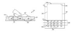
- the user interface systemincludes a first sensor portion 140 a that includes at least one horizontal conductor 244 and at least one vertical conductor 242 and functions to detect user input anywhere along the surface 115 and a second sensor portion 140 b that includes a set of first conductors 246 and a set of second conductors 248 and functions to detect user input only at the particular regions 113 .
- the processor 160functions to determine which of the first and second sensing systems 140 a and 140 b to be used for detection of user input at any one time.
- the first sensor portion 140 amay be the default sensing system until an application of the device activates the expansion of the cavities 125 and deforms the particular regions 113 .
- the second sensor portion 140 bis then used to provide substantially more accurate details of user input (for example, speed of user input, direction of user input, pressure of user input, or the amount of inward deformation of the particular region 113 ) at the particular regions 113 .
- the user interface systempreferably returns to utilizing the first sensor portion 140 a .
- both the first sensor portion 140 a and the second sensor portion 140 bmay be used concurrently when the expansion of the cavities 125 is activated to allow for increased accuracy in the details of the user input at the particular regions 113 as well as detection of user input at locations away from the portion of the surface 115 that includes the particular regions 113 .
- the user interface system of the first preferred embodimentmay include a first driver chip that cooperates with the first sensor portion 140 a and a second driver chip that cooperates with the second system 140 b , but may alternatively include one driver chip that drives both the first and second sensing systems 140 a and 140 b .
- any other suitable arrangement of the driver chips and the processor 160may be used.
- the first sensor portion 140 amay be of a type that is known in the art and the second sensor portion 140 b is preferably one that has been described in U.S. application Ser. No. 12/497,622.
- the first sensor portion 140 amay include vertical conductors 242 and 243 substantially at the left and right edges of the surface 115 and horizontal conductors 244 and 246 substantially at the top and bottom edges of the surface 115 .
- An electric fieldis provided by a vertical conductor 242 and a horizontal conductor 244 that is detected by the other vertical conductor 243 and the other horizontal conductor 246 .
- An example of electric field generationmay be by transmitting a current through the vertical conductor 242 and the horizontal conductor 244 that creates an electric field that is detected by the by the other vertical conductor 243 and the other horizontal conductor 246 .
- any other suitable method of generating an electric fieldmay be used.
- the presence of a fingermay cause disruptions and/or fluctuations in the electric field that are detected and the location of the finger may be triangulated from the electric field that is felt by the electric field receivers vertical conductor 243 and horizontal conductor 246 .
- an electric fieldmay be provided only by the horizontal conductors 244 and 246 or only by the vertical conductors 242 and 243 .
- any other suitable arrangement of providing detectable electric fieldsmay be used.
- the method known in the art of projected capacitancemay be used to detect user input.
- the first sensor portion 140 a of this variationpreferably includes a grid of vertical conductors 242 and horizontal conductors 244 where the location of electric field fluctuations due to a finger or any other suitable body part or object is more accurately detected, allowing advanced touch sensing applications such as multi-finger touch.
- the first sensor portion 140 amay also sense the presence and the location of the user input by using surface capacitance where the sheet 102 may include a layer of conductive material to which a voltage is applied.
- the conductive layeris preferably transparent and/or index matched with the rest of the sheet 102 and preferably is located away from the surface 115 .
- the conductors of the first sensor portion 140 amay be arranged diagonally, in a cross pattern, or any other suitable orientation.
- the conductors of the first sensor portion 140 amay also be of any other suitable shape (for example, the conductors may resemble a sine wave), size, or geometry.
- any other suitable capacitive touch system known in the artmay be used for the first sensor portion 140 a and the second sensor portion 140 b.
- the second sensor portion 140 bmay include a first and second conductor at a particular region 113 and the distance between the first and second conductor changes when a user provides an input at the particular region to detect and receive a user input.
- the distance between first and second conductor at the particular region 113preferably decreases as a user input is provided at the particular region 113 (for example, one that inwardly deforms the particular region 113 ), but may alternatively increase.
- the first and second conductormay alternatively come into contact to substantially detect a user input substantially proximal to the particular region 113 .
- the second sensor portion 140 bincludes conductors that are configured to detect a user input at the particular region 113 , the sensitivity for detection of a user input, determining the location of the user input, and/or detecting any other suitable characteristic of the user input may be increased. However, any other suitable arrangement of conductors may be used for the second sensor portion 140 b to provide the higher second sensitivity to a user input provided substantially proximal to the particular region 113 .
- the second preferred embodimentpreferably includes a sensing system that allows for the detection of both user inputs at a particular region 113 and anywhere along the surface 115 at the second and first sensitivities, respectively, without the need of an additional sensor system (for example, a first sensor system to detect the presence and/or properties of user inputs at a particular region 113 and a second sensor system to detect the presence and/or properties of user inputs elsewhere along the surface 115 ).
- the sensor 140 of the second preferred embodimentpreferably utilizes one driver chip that cooperates to detect both user inputs at a particular region 113 and anywhere else along the surface 115 .
- the senor 140preferably includes a first sensing portion 140 a that includes elongated vertical conductors 242 (shown as 242 a and 242 b ), and non-array horizontal conductor 244 with a first sensitivity to a user input and a second sensing portion 140 b that includes horizontal array conductors 246 (three horizontal array conductors 246 a , 246 b , and 246 c are shown, but may be any other suitable number), vertical array conductors 248 (three vertical array conductors 248 a , 248 b , and 248 c are shown, but may be any other suitable number), that increases the sensitivity to the second sensitivity substantially proximal to the particular region 113 of the surface.
- the horizontal and vertical array conductors 246 and 248 of the second sensor portion 140 bare preferably of the type of conductor 142 and 144 , respectively, as described in U.S. application Ser. No. 12/497,622.
- the elongated vertical conductors 242 of the first sensor portion 140 aare preferably of the same conductor type as the vertical array conductors 248 and extend through a column of cavities 125 to a portion of the surface 115 that does not include a particular region 113 . In the substantially rectangular surface 115 as shown in FIGS.
- one elongated vertical conductor 242preferably corresponds to the left most column of cavities 125 and a second elongated vertical conductor 242 preferably corresponds to the right most column of cavities 125 and both preferably extend from the bottom corners of the rectangle to the upper corners of the rectangle, preferably forming a bracket around a substantially large portion of the surface 115 .
- the non-array horizontal conductor 244is preferably of the same conductor type as the horizontal array conductors 246 and is preferably located at a portion of the surface that does not include a particular region 113 . In the substantially rectangular surface 115 as shown in FIGS.
- the non-array horizontal conductor 244preferably extends from the two side corners of the rectangle, preferably cooperating with the horizontal array conductor 246 c corresponding with the bottom most row of cavities 125 to form a bracket around a substantially large portion of the surface 115 .
- the elongated vertical conductors 242 , the non-array horizontal conductor 243 , and the horizontal array conductor 246 c corresponding to the bottom most row of the cavities 125may resemble the conductors of the first example of the first sensor portion 140 a of the first preferred embodiment.
- an additional non-array horizontal conductor 244may be used instead of the horizontal array conductor 246 corresponding to the bottom most row of the cavities 125 to form a bracket around a substantially large portion of the surface 115 .
- the elongated vertical conductors 242 and non-array horizontal conductor 244may be arranged diagonally, in a cross pattern, or any other suitable orientation.
- the elongated vertical conductors 242 and non-array horizontal conductor 244may also be of any other suitable shape (for example, the conductors may resemble a sine wave), size, or geometry.
- the portion of the elongated vertical conductor 242 that corresponds to a particular region 113may be of the same conductor type and/or geometry as the vertical array conductors 248 while a second portion of the elongated vertical conductor 242 that corresponds to a portion of the surface 115 that does not include a particular region 113 may be of a different conductor type and/or geometry.
- any other suitable material or arrangement of the horizontal and vertical array conductors 246 and 248 , elongated vertical conductor 242 , and non-array horizontal conductor 244may be used.
- the sensing system of the second preferred embodimentis described in the substantially rectangular surface 115 as shown in the FIGURES, the sensing system may be accommodated to any other suitable geometry of the surface 115 (for example, circular or octagonal) and may also be accommodated to any suitable type of surface plane (for example, substantially flat or curved). Additionally, the particular regions 113 may be arranged in any suitable pattern. The particular regions 113 may also occupy a substantial portion of the surface 115 .
- the sensing system of this variationmay utilize a second horizontal array conductor 246 to function as the non-array horizontal conductor 244 . However, any other suitable arrangement of the sensing system may be used.
- an electric fieldis provided by a conductor (for example, by means of a current through the conductor) and the electric field is detected by a second conductor such that disruptions and/or fluctuations caused by the presence of a finger in the electric field may also be detected.
- the second conductormay function to scan across the plurality of electric fields at a plurality of combinations of conductor pairs to detect a user input.
- the second conductormay act as a conductor that is connected to ground and cooperates with the first conductor to create an electric field that may be disrupted by the presence of a finger.
- the user interface systempreferably also functions to discern between a user input at a particular region 113 and a user input at a portion of the surface 115 that does not include a particular region 113 . This may be achieved using one of several variations of the capacitive sensor system 140 .
- each of the vertical array conductors 248 and the elongated vertical conductors 242 and the horizontal array conductors 246 and the non-array horizontal conductor 244each function to detect the change in the electric fields generated by the vertical conductors 248 and 242 .
- the electric signal that is transmitted through each of the vertical array conductors 248is preferably at a first frequency and the electric signal that is transmitted through the elongated vertical conductors 242 is preferably at a second frequency, where the first and second frequencies are substantially different.
- the first and second frequenciesare preferably not harmonics of each other and the frequency offset between the first and second frequencies is preferably not of the frequency of the electrical grid (for example, 60 hertz in North America) or some other frequency that is commonly present in electronic devices (for example, the refresh frequency in a liquid crystal display or LCD) to decrease interference.
- the electric field conductorsmay discern a user input at the particular region 113 from a user input elsewhere on the surface 115 .
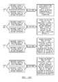
- An example of a method of discerning such user inputis: 1.
- This methodis preferably carried out by a processor 160 through software and digital signal processing, but may alternatively be carried out through electrical circuitry, such as an FPGA. As shown in FIG.
- the user interface systempreferably discerns between a user input at the particular region 113 (input A), at a portion of the surface 115 that does not include a particular region 113 but is in relative proximity to an elongated vertical conductor 242 (Input B), at a particular region 113 that is relatively central to the portion of the surface 115 that includes a group of particular regions 113 (Input C), at a portion of substantially central to a portion of the surface 115 that does not include a particular region 113 (Input D), and at a portion of the surface 115 that includes a particular region 113 but not at a particular region 113 (Input E).
- the user interface systempreferably also functions to discern between any other suitable locations of user inputs.
- the electric field of the second frequencymay be employed only when the cavities 125 are in the expanded state.
- the elongated vertical conductors 242 a and 242 b , the horizontal array conductor 246 c and the non-array horizontal 244may be employed using an electric field of the first frequency to determine the location of a user input while other conductors are inactive.
- the human bodyacts as a dielectric and increases the capacitance between two conductors when placed within the electric field that between the conductors. The closer a part of the human body (for example, the finger of the user) is placed to a conductor, the overall larger the change in the capacitance between the conductors.
- the processor 160may function to utilize this property of electric fields and capacitance to determine the location and the type of user input that is detected, as shown in FIG. 15 c .
- the user interface systemmay infer that the input is the portion of the surface 115 that includes a particular region 113 and will preferably primarily detecting changes in the electric field of the second frequency.
- the change in the electric fields of the first and second frequency as felt by horizontal array conductors 246 b and 246 cmay also be used to triangulate the location of the user input.
- the elongated vertical conductor 242 amay come into contact with the horizontal array conductor 246 a at the particular region 113 and provide a second signal to indicate that the user input is at the particular region 113 .
- any other suitable method to determine that the user input is located at the particular region 113may be used.
- the user interface systemmay determine that the user input is located at the portion of the surface 115 that does not include a particular region 113 and will preferably primarily detect changes in the electric field of the first frequency through use of the non-array horizontal conductor 244 , elongated vertical conductors 242 a and b , and horizontal array conductor 246 c .
- the location of the Input Bmay be determined using methods known in the art for triangulating the location of a user input using the four conductors, for example, comparing the change in the electric field of the first frequency as received by the non-array horizontal conductor 244 and the horizontal array conductor 248 c .
- the same methodsmay be applied to determining an Input D that is substantially central to the portion of the surface 115 that does not include a particular region 113 .
- the change in the electric field of the second frequency as felt by horizontal array conductor 246 ais substantially large.
- the change in the electric field of the first frequency as felt by the horizontal array conductor 246 ais smaller than in the case of Input A.
- the user interface systemmay infer that the use input is at the portion of the surface 115 that includes the particular regions, but is located at a location substantially far from the elongated vertical conductors 242 a and b and will preferably switch to detecting only changes in the electric field of the second frequency.
- the change in the electric fields of the first and second frequency as felt by horizontal array conductors 246 b and cmay also be used to triangulate the location of the user input.
- the vertical array conductor 248 bmay come into contact with the horizontal array conductor 246 a at the particular region 113 and provide a second signal to indicate that the user input is at the particular region 113 .
- any other suitable method to determine that the user input is located at the particular region 113may be used.
- the change in the electric field of the first frequency as felt by the horizontal array conductor 246 ais substantially small while the change in the electric field of the second frequency as felt by horizontal array conductor 246 a is substantially large and the user interface system preferably infers that the user input is located at a portion of the surface 115 that includes a particular region 113 .
- the change in the electric fields of the first and/or second frequency as felt by horizontal array conductors 246 b and cmay also be used to triangulate the location of the user input.
- the user interface systemmay infer that the user input is located in between a particular region 113 that corresponds to the horizontal array conductor 246 a and a particular region 113 that corresponds to the horizontal array conductor 246 b .
- the absence of contact while a substantially large change in the electric field is detectedmay be used to determine that the user input is in close proximity to a particular region 113 .
- any other suitable method to determine the location of the Input Emay be used.
- the processor 160may determine the location of the of the user input and, when the user input is detected to be at a particular region 113 , the processor 160 may primarily detect changes in the electric field of the second frequency. To determine that the user input is located at the particular region 113 , the change in the electric fields of the first and second frequency as detected by the sensing system may be used to triangulate the location of the user input. The processor 160 may function to evaluate the changes in the electric fields of the first and second frequencies independently to determine the location of the user input, but may alternatively evaluate changes in the electric fields of the first and second frequencies together, which may achieve a more accurate determination of user input location.
- the elongated vertical conductor 242 amay come into contact with the horizontal array conductor 246 a at the particular region 113 and provide a second signal to indicate that the user input is at the particular region 113 .
- any other suitable method to determine that the user input is located at the particular region 113may be used.
- the second sensor portion 140 bmay include a first and second conductor at a particular region 113 , as described in U.S. application Ser. No. 12/497,622.
- the distance between the first and second conductorchanges when a user provides an input at the particular region to detect and receive a user input.
- the distance between first and second conductor at the particular region 113preferably decreases as a user input is provided at the particular region 113 (for example, one that inwardly deforms the particular region 113 ), but may alternatively increase.
- the first and second conductormay alternatively come into contact to substantially acutely detect a user input substantially proximal to the particular region 113 .
- the first and second conductormay alternatively come into contact to substantially acutely detect a user input substantially proximal to the particular region 113 .
- the second sensor portion 140 bincludes conductors that are configured to detect a user input at the particular region 113 , the sensitivity for detection of a user input, determining the location of the user input, and/or detecting any other suitable characteristic of the user input may be increased.
- any other suitable arrangement of conductorsmay be used for the second sensor portion 140 b to provide the higher second sensitivity to a user input provided substantially proximal to the particular region 113 .
- the sensor systemmay substantially similar or identical to that of the first sensor portion 140 a of the first preferred embodiment.
- the sensor systemfunctions to determine the location of the user input.
- substantially more accurate details of user inputfor example, speed of user input, direction of user input, pressure of user input, or the amount of inward deformation of the particular region 113 .
- the sensor 140 of the preferred embodimentsis preferably one of the variations and arrangements described above, but may alternatively be any other suitable variation or arrangement.
- a current of a unique frequencymay be transmitted through each electric field emitting conductor (elongated vertical conductors 242 and vertical array conductors 248 ), resulting in a plurality of electric fields that are each of a different frequency, which may facilitate in determining the location of the user input.
- the horizontal array conductors 246 and the non-array horizontal conductor 244 as the electric field emitters and the vertical array conductors 248 and the elongated vertical conductors 242may function as the electric field receivers.
- user inputs located at a particular region 113may be detected by the a horizontal array conductor coming into contact with a vertical array conductor (or elongated vertical conductor) while user input located at a portion of the surface 115 that does not include a particular region 113 may be detected from disruptions in the electric field.
- any other suitable methodthat allows for user inputs both located at a portion of the surface 115 that includes a particular region 115 and at a portion of the surface 115 that does not include a particular region 115 to be detected simultaneously may be used.
- the sensor 140may also function to detect the occurrence of multiple user inputs (commonly known as “multi-touch”), in various combinations: multiple user inputs, each at a different particular region 113 , each at various locations on the surface 115 that do not include a particular region 113 , or a combination of inputs at both the particular regions 113 and at locations on the surface 115 that do not include a particular region 113 .
- multi-touchcommonly known as “multi-touch”
- the fluid 112may affect the electromagnetic fields that are generated within the sensor system 140 , for example, the fluid itself may be conductive, the fluid may include suspensions or dispersions of particles with relevant electrical and optical properties, or the any other suitable type of fluid.
- the fluid 112may function as an electrical conductor or an electrical insulator that manipulates an electromagnetic field that passes through the fluid 112 .
- the fluid 112may be directed within the sheet 102 to provide desired manipulations of an electromagnetic field, for example, to increase the sensitivity of the sensor system 140 at particular portions and/or to decrease the sensitivity of the sensor system at another portion.
- the processor 160may be configured to recognize the affect that the fluid 112 may have on the electromagnetic fields of the sensor 140 and to adjust the method of detecting a user touch when effects from the fluid 112 are detected.
- the processor 160may be configured to recognize the affect that the fluid 112 may have on the electromagnetic fields of the sensor 140 and to adjust the method of detecting a user touch when effects from the fluid 112 are detected.
- any other suitable use and/or accommodation to the effects of the fluid 112 on the electromagnetic fields of the sensor system 140may be used.
Landscapes
- Engineering & Computer Science (AREA)
- General Engineering & Computer Science (AREA)
- Theoretical Computer Science (AREA)
- Human Computer Interaction (AREA)
- Physics & Mathematics (AREA)
- General Physics & Mathematics (AREA)
- User Interface Of Digital Computer (AREA)
- Position Input By Displaying (AREA)
Abstract
Description
Claims (31)
Priority Applications (3)
| Application Number | Priority Date | Filing Date | Title |
|---|---|---|---|
| US12/975,337US8922503B2 (en) | 2008-01-04 | 2010-12-21 | User interface system |
| US14/514,134US9207795B2 (en) | 2008-01-04 | 2014-10-14 | User interface system |
| US14/927,859US20160054833A1 (en) | 2008-01-04 | 2015-10-30 | User interface system |
Applications Claiming Priority (5)
| Application Number | Priority Date | Filing Date | Title |
|---|---|---|---|
| US11/969,848US8547339B2 (en) | 2008-01-04 | 2008-01-04 | System and methods for raised touch screens |
| US12/319,334US8154527B2 (en) | 2008-01-04 | 2009-01-05 | User interface system |
| US12/497,622US8179375B2 (en) | 2008-01-04 | 2009-07-03 | User interface system and method |
| US28882609P | 2009-12-21 | 2009-12-21 | |
| US12/975,337US8922503B2 (en) | 2008-01-04 | 2010-12-21 | User interface system |
Related Parent Applications (2)
| Application Number | Title | Priority Date | Filing Date |
|---|---|---|---|
| US12/319,334Continuation-In-PartUS8154527B2 (en) | 2008-01-04 | 2009-01-05 | User interface system |
| US12/497,622Continuation-In-PartUS8179375B2 (en) | 2008-01-04 | 2009-07-03 | User interface system and method |
Related Child Applications (1)
| Application Number | Title | Priority Date | Filing Date |
|---|---|---|---|
| US14/514,134ContinuationUS9207795B2 (en) | 2008-01-04 | 2014-10-14 | User interface system |
Publications (2)
| Publication Number | Publication Date |
|---|---|
| US20110157080A1 US20110157080A1 (en) | 2011-06-30 |
| US8922503B2true US8922503B2 (en) | 2014-12-30 |
Family
ID=44304566
Family Applications (3)
| Application Number | Title | Priority Date | Filing Date |
|---|---|---|---|
| US12/975,337Expired - Fee RelatedUS8922503B2 (en) | 2008-01-04 | 2010-12-21 | User interface system |
| US14/514,134Expired - Fee RelatedUS9207795B2 (en) | 2008-01-04 | 2014-10-14 | User interface system |
| US14/927,859AbandonedUS20160054833A1 (en) | 2008-01-04 | 2015-10-30 | User interface system |
Family Applications After (2)
| Application Number | Title | Priority Date | Filing Date |
|---|---|---|---|
| US14/514,134Expired - Fee RelatedUS9207795B2 (en) | 2008-01-04 | 2014-10-14 | User interface system |
| US14/927,859AbandonedUS20160054833A1 (en) | 2008-01-04 | 2015-10-30 | User interface system |
Country Status (4)
| Country | Link |
|---|---|
| US (3) | US8922503B2 (en) |
| EP (1) | EP2517089A4 (en) |
| CN (1) | CN102782617B (en) |
| WO (1) | WO2011087817A1 (en) |
Cited By (19)
| Publication number | Priority date | Publication date | Assignee | Title |
|---|---|---|---|---|
| US20160054833A1 (en)* | 2008-01-04 | 2016-02-25 | Tactus Technology, Inc. | User interface system |
| US9477308B2 (en) | 2008-01-04 | 2016-10-25 | Tactus Technology, Inc. | User interface system |
| US9495055B2 (en) | 2008-01-04 | 2016-11-15 | Tactus Technology, Inc. | User interface and methods |
| US9552065B2 (en) | 2008-01-04 | 2017-01-24 | Tactus Technology, Inc. | Dynamic tactile interface |
| US9557813B2 (en) | 2013-06-28 | 2017-01-31 | Tactus Technology, Inc. | Method for reducing perceived optical distortion |
| US9557915B2 (en) | 2008-01-04 | 2017-01-31 | Tactus Technology, Inc. | Dynamic tactile interface |
| US20170052073A1 (en)* | 2015-08-19 | 2017-02-23 | Preh Gmbh | Capacitive control element with improved malfunction immunity |
| US9588683B2 (en) | 2008-01-04 | 2017-03-07 | Tactus Technology, Inc. | Dynamic tactile interface |
| US9588684B2 (en) | 2009-01-05 | 2017-03-07 | Tactus Technology, Inc. | Tactile interface for a computing device |
| US9612659B2 (en) | 2008-01-04 | 2017-04-04 | Tactus Technology, Inc. | User interface system |
| US9619030B2 (en) | 2008-01-04 | 2017-04-11 | Tactus Technology, Inc. | User interface system and method |
| US9619032B1 (en) | 2015-10-16 | 2017-04-11 | International Business Machines Corporation | Accessibility path guiding through microfluidics on a touch screen |
| US9626059B2 (en) | 2008-01-04 | 2017-04-18 | Tactus Technology, Inc. | User interface system |
| US9720501B2 (en) | 2008-01-04 | 2017-08-01 | Tactus Technology, Inc. | Dynamic tactile interface |
| US9760172B2 (en) | 2008-01-04 | 2017-09-12 | Tactus Technology, Inc. | Dynamic tactile interface |
| US10401962B2 (en) | 2016-06-21 | 2019-09-03 | Immersion Corporation | Haptically enabled overlay for a pressure sensitive surface |
| US10747404B2 (en)* | 2017-10-24 | 2020-08-18 | Microchip Technology Incorporated | Touchscreen including tactile feedback structures and corresponding virtual user interface elements |
| US10959674B2 (en) | 2017-10-23 | 2021-03-30 | Datafeel Inc. | Communication devices, methods, and systems |
| US11934583B2 (en) | 2020-10-30 | 2024-03-19 | Datafeel Inc. | Wearable data communication apparatus, kits, methods, and systems |
Families Citing this family (79)
| Publication number | Priority date | Publication date | Assignee | Title |
|---|---|---|---|---|
| US8154527B2 (en) | 2008-01-04 | 2012-04-10 | Tactus Technology | User interface system |
| US8704790B2 (en) | 2010-10-20 | 2014-04-22 | Tactus Technology, Inc. | User interface system |
| US8547339B2 (en) | 2008-01-04 | 2013-10-01 | Tactus Technology, Inc. | System and methods for raised touch screens |
| US8922510B2 (en) | 2008-01-04 | 2014-12-30 | Tactus Technology, Inc. | User interface system |
| US9298261B2 (en) | 2008-01-04 | 2016-03-29 | Tactus Technology, Inc. | Method for actuating a tactile interface layer |
| US9052790B2 (en) | 2008-01-04 | 2015-06-09 | Tactus Technology, Inc. | User interface and methods |
| US8243038B2 (en) | 2009-07-03 | 2012-08-14 | Tactus Technologies | Method for adjusting the user interface of a device |
| US8456438B2 (en) | 2008-01-04 | 2013-06-04 | Tactus Technology, Inc. | User interface system |
| US9128525B2 (en) | 2008-01-04 | 2015-09-08 | Tactus Technology, Inc. | Dynamic tactile interface |
| US8553005B2 (en) | 2008-01-04 | 2013-10-08 | Tactus Technology, Inc. | User interface system |
| US9430074B2 (en) | 2008-01-04 | 2016-08-30 | Tactus Technology, Inc. | Dynamic tactile interface |
| US8570295B2 (en) | 2008-01-04 | 2013-10-29 | Tactus Technology, Inc. | User interface system |
| US8947383B2 (en) | 2008-01-04 | 2015-02-03 | Tactus Technology, Inc. | User interface system and method |
| US9423875B2 (en) | 2008-01-04 | 2016-08-23 | Tactus Technology, Inc. | Dynamic tactile interface with exhibiting optical dispersion characteristics |
| WO2010036545A2 (en)* | 2008-09-24 | 2010-04-01 | 3M Innovative Properties Company | Mutual capacitance measuring circuits and methods |
| US20150077398A1 (en)* | 2013-06-27 | 2015-03-19 | Tactus Technology, Inc. | Method for interacting with a dynamic tactile interface |
| CN102460357B (en)* | 2009-05-29 | 2016-04-27 | 3M创新有限公司 | High-speed multi-touch touch device and its controller |
| WO2011003113A1 (en) | 2009-07-03 | 2011-01-06 | Tactus Technology | User interface enhancement system |
| US9753586B2 (en)* | 2009-10-08 | 2017-09-05 | 3M Innovative Properties Company | Multi-touch touch device with multiple drive frequencies and maximum likelihood estimation |
| US8773366B2 (en)* | 2009-11-16 | 2014-07-08 | 3M Innovative Properties Company | Touch sensitive device using threshold voltage signal |
| WO2011087816A1 (en)* | 2009-12-21 | 2011-07-21 | Tactus Technology | User interface system |
| US8411066B2 (en)* | 2010-01-05 | 2013-04-02 | 3M Innovative Properties Company | High speed noise tolerant multi-touch touch device and controller therefor |
| US9298262B2 (en) | 2010-01-05 | 2016-03-29 | Tactus Technology, Inc. | Dynamic tactile interface |
| US8619035B2 (en) | 2010-02-10 | 2013-12-31 | Tactus Technology, Inc. | Method for assisting user input to a device |
| WO2011112984A1 (en) | 2010-03-11 | 2011-09-15 | Tactus Technology | User interface system |
| WO2011133605A1 (en) | 2010-04-19 | 2011-10-27 | Tactus Technology | Method of actuating a tactile interface layer |
| EP2577434A2 (en) | 2010-05-25 | 2013-04-10 | 3M Innovative Properties Company | High speed low power multi-touch touch device and controller therefor |
| US10019119B2 (en) | 2010-09-09 | 2018-07-10 | 3M Innovative Properties Company | Touch sensitive device with stylus support |
| US9389724B2 (en) | 2010-09-09 | 2016-07-12 | 3M Innovative Properties Company | Touch sensitive device with stylus support |
| US9823785B2 (en) | 2010-09-09 | 2017-11-21 | 3M Innovative Properties Company | Touch sensitive device with stylus support |
| US8975903B2 (en) | 2011-06-09 | 2015-03-10 | Ford Global Technologies, Llc | Proximity switch having learned sensitivity and method therefor |
| US8928336B2 (en) | 2011-06-09 | 2015-01-06 | Ford Global Technologies, Llc | Proximity switch having sensitivity control and method therefor |
| US10004286B2 (en) | 2011-08-08 | 2018-06-26 | Ford Global Technologies, Llc | Glove having conductive ink and method of interacting with proximity sensor |
| US9143126B2 (en) | 2011-09-22 | 2015-09-22 | Ford Global Technologies, Llc | Proximity switch having lockout control for controlling movable panel |
| US10112556B2 (en) | 2011-11-03 | 2018-10-30 | Ford Global Technologies, Llc | Proximity switch having wrong touch adaptive learning and method |
| US8994228B2 (en) | 2011-11-03 | 2015-03-31 | Ford Global Technologies, Llc | Proximity switch having wrong touch feedback |
| US8878438B2 (en) | 2011-11-04 | 2014-11-04 | Ford Global Technologies, Llc | Lamp and proximity switch assembly and method |
| US9944237B2 (en) | 2012-04-11 | 2018-04-17 | Ford Global Technologies, Llc | Proximity switch assembly with signal drift rejection and method |
| US9287864B2 (en) | 2012-04-11 | 2016-03-15 | Ford Global Technologies, Llc | Proximity switch assembly and calibration method therefor |
| US9184745B2 (en) | 2012-04-11 | 2015-11-10 | Ford Global Technologies, Llc | Proximity switch assembly and method of sensing user input based on signal rate of change |
| US9520875B2 (en) | 2012-04-11 | 2016-12-13 | Ford Global Technologies, Llc | Pliable proximity switch assembly and activation method |
| US9065447B2 (en) | 2012-04-11 | 2015-06-23 | Ford Global Technologies, Llc | Proximity switch assembly and method having adaptive time delay |
| US9660644B2 (en) | 2012-04-11 | 2017-05-23 | Ford Global Technologies, Llc | Proximity switch assembly and activation method |
| US9559688B2 (en) | 2012-04-11 | 2017-01-31 | Ford Global Technologies, Llc | Proximity switch assembly having pliable surface and depression |
| US9197206B2 (en) | 2012-04-11 | 2015-11-24 | Ford Global Technologies, Llc | Proximity switch having differential contact surface |
| US9831870B2 (en) | 2012-04-11 | 2017-11-28 | Ford Global Technologies, Llc | Proximity switch assembly and method of tuning same |
| US8933708B2 (en) | 2012-04-11 | 2015-01-13 | Ford Global Technologies, Llc | Proximity switch assembly and activation method with exploration mode |
| US9531379B2 (en) | 2012-04-11 | 2016-12-27 | Ford Global Technologies, Llc | Proximity switch assembly having groove between adjacent proximity sensors |
| US9568527B2 (en) | 2012-04-11 | 2017-02-14 | Ford Global Technologies, Llc | Proximity switch assembly and activation method having virtual button mode |
| US9219472B2 (en) | 2012-04-11 | 2015-12-22 | Ford Global Technologies, Llc | Proximity switch assembly and activation method using rate monitoring |
| US9136840B2 (en) | 2012-05-17 | 2015-09-15 | Ford Global Technologies, Llc | Proximity switch assembly having dynamic tuned threshold |
| US8981602B2 (en) | 2012-05-29 | 2015-03-17 | Ford Global Technologies, Llc | Proximity switch assembly having non-switch contact and method |
| US9337832B2 (en) | 2012-06-06 | 2016-05-10 | Ford Global Technologies, Llc | Proximity switch and method of adjusting sensitivity therefor |
| US9641172B2 (en) | 2012-06-27 | 2017-05-02 | Ford Global Technologies, Llc | Proximity switch assembly having varying size electrode fingers |
| US8922340B2 (en) | 2012-09-11 | 2014-12-30 | Ford Global Technologies, Llc | Proximity switch based door latch release |
| US9405417B2 (en) | 2012-09-24 | 2016-08-02 | Tactus Technology, Inc. | Dynamic tactile interface and methods |
| WO2014047656A2 (en)* | 2012-09-24 | 2014-03-27 | Tactus Technology, Inc. | Dynamic tactile interface and methods |
| US8796575B2 (en) | 2012-10-31 | 2014-08-05 | Ford Global Technologies, Llc | Proximity switch assembly having ground layer |
| WO2014081808A1 (en)* | 2012-11-20 | 2014-05-30 | Arizona Board Of Regents, A Body Corporate Of The State Of Arizona, Acting For And On Behalf Of Arizon State University | Responsive dynamic three-dimensional tactile display using hydrogel |
| US9075429B1 (en)* | 2012-12-19 | 2015-07-07 | Amazon Technologies, Inc. | Distortion correction for device display |
| US8890841B2 (en) | 2013-03-13 | 2014-11-18 | 3M Innovative Properties Company | Capacitive-based touch apparatus and method therefor, with reduced interference |
| US9311204B2 (en) | 2013-03-13 | 2016-04-12 | Ford Global Technologies, Llc | Proximity interface development system having replicator and method |
| US20140347312A1 (en)* | 2013-05-24 | 2014-11-27 | Andrew Siska | Method for Rejecting a Touch-Swipe Gesture as an Invalid Touch |
| KR102174679B1 (en) | 2013-12-31 | 2020-11-06 | 엘지디스플레이 주식회사 | Touch panel |
| US9176617B2 (en) | 2014-02-14 | 2015-11-03 | Lenovo Enterprise Solutions (Singapore) Pte. Ltd. | Physical presence of a virtual button on a touch screen of an electronic device |
| US9335848B2 (en) | 2014-02-14 | 2016-05-10 | Lenovo Enterprise Solutions (Singapore) Pte. Ltd. | Apparatus for providing a three dimensional tactile display of an electronic device |
| JP5961197B2 (en)* | 2014-02-18 | 2016-08-02 | 本田技研工業株式会社 | Operation system |
| US10038443B2 (en) | 2014-10-20 | 2018-07-31 | Ford Global Technologies, Llc | Directional proximity switch assembly |
| US9791929B2 (en)* | 2014-10-31 | 2017-10-17 | Elwha Llc | Tactile control system |
| US10083633B2 (en) | 2014-11-10 | 2018-09-25 | International Business Machines Corporation | Generating a three-dimensional representation of a topography |
| US9916008B2 (en) | 2015-01-12 | 2018-03-13 | International Business Machines Corporation | Microfluidics three-dimensional touch screen display |
| US9654103B2 (en) | 2015-03-18 | 2017-05-16 | Ford Global Technologies, Llc | Proximity switch assembly having haptic feedback and method |
| US9548733B2 (en) | 2015-05-20 | 2017-01-17 | Ford Global Technologies, Llc | Proximity sensor assembly having interleaved electrode configuration |
| WO2016205375A1 (en)* | 2015-06-18 | 2016-12-22 | The Regents Of The University Of Michigan | Microfluidic actuators with integrated addressing |
| GB201511042D0 (en)* | 2015-06-23 | 2015-08-05 | Royal College Of Art And Kong Ming | Sensor device and method |
| TWI571770B (en)* | 2015-11-20 | 2017-02-21 | 致伸科技股份有限公司 | Illuminated keyboard |
| CN109634411B (en)* | 2018-11-29 | 2020-10-27 | 北京航空航天大学 | Texture feedback device based on network structure |
| CN111880639B (en)* | 2020-02-21 | 2021-03-26 | 玉环墨痕机电科技有限公司 | Method for dynamically adjusting sensitivity of mobile phone touch screen |
| US11481069B2 (en)* | 2020-09-15 | 2022-10-25 | International Business Machines Corporation | Physical cursor control in microfluidic display devices |
Citations (359)
| Publication number | Priority date | Publication date | Assignee | Title |
|---|---|---|---|---|
| US3034628A (en) | 1960-10-31 | 1962-05-15 | Sperry Rand Corp | Pneumatic keyboard |
| US3659354A (en) | 1970-10-21 | 1972-05-02 | Mitre Corp | Braille display device |
| US3759108A (en) | 1971-09-16 | 1973-09-18 | Gen Electric | Single gauge multi-time constant and multi-tissue ratio automatic decompression instruments |
| US3780236A (en) | 1971-05-18 | 1973-12-18 | Gen Signal Corp | Push button switch assembly with slidable interlocking means preventing simultaneous operation of two or more pushbuttons |
| US3818487A (en) | 1972-08-24 | 1974-06-18 | W Brody | Soft control materials |
| US4109118A (en) | 1976-09-01 | 1978-08-22 | Victor Kley | Keyswitch pad |
| US4209819A (en) | 1978-03-13 | 1980-06-24 | Key Tronic Corporation | Capacitive keyswitch |
| US4290343A (en) | 1978-10-30 | 1981-09-22 | Mts Systems Corporation | High volume poppet valve with orifice opening speed control |
| US4307268A (en) | 1978-11-17 | 1981-12-22 | Rogers Corporation | Tactile element and keyboard including the tactile element |
| US4467321A (en) | 1982-04-30 | 1984-08-21 | Volnak William M | Chording keyboard for generating binary data |
| US4477700A (en) | 1983-11-14 | 1984-10-16 | Rogers Corporation | Tactile membrane keyboard with elliptical tactile key elements |
| US4517421A (en) | 1980-01-28 | 1985-05-14 | Margolin George D | Resilient deformable keyboard |
| US4543000A (en) | 1981-10-13 | 1985-09-24 | Hasenbalg Ralph D | Latching actuator |
| US4700025A (en) | 1986-05-23 | 1987-10-13 | Alps Electric Co., Ltd. | Transparent touch-sensitive panel |
| US4920343A (en) | 1988-09-30 | 1990-04-24 | Honeywell Inc. | Capacitive keyswitch membrane with self contained sense-to-ground capacitance |
| US5194852A (en) | 1986-12-01 | 1993-03-16 | More Edward S | Electro-optic slate for direct entry and display and/or storage of hand-entered textual and graphic information |
| US5195659A (en) | 1991-11-04 | 1993-03-23 | Eiskant Ronald E | Discreet amount toothpaste dispenser |
| US5212473A (en) | 1991-02-21 | 1993-05-18 | Typeright Keyboard Corp. | Membrane keyboard and method of using same |
| US5286199A (en) | 1991-10-04 | 1994-02-15 | Siegfried Kipke | Electromechanical transducer |
| US5412189A (en) | 1992-12-21 | 1995-05-02 | International Business Machines Corporation | Touch screen apparatus with tactile information |
| US5459461A (en) | 1993-07-29 | 1995-10-17 | Crowley; Robert J. | Inflatable keyboard |
| US5488204A (en) | 1992-06-08 | 1996-01-30 | Synaptics, Incorporated | Paintbrush stylus for capacitive touch sensor pad |
| US5496174A (en)* | 1994-08-04 | 1996-03-05 | The United States Of America As Represented By The Administrator Of The National Aeronautics And Space Administration | Method and device for producing a tactile display using an electrorheological fluid |
| US5717423A (en) | 1994-12-30 | 1998-02-10 | Merltec Innovative Research | Three-dimensional display |
| US5729222A (en) | 1993-05-21 | 1998-03-17 | Jerry Iggulden | User-configurable control device |
| US5754023A (en) | 1995-10-26 | 1998-05-19 | Cybernet Systems Corporation | Gyro-stabilized platforms for force-feedback applications |
| US5766013A (en) | 1995-03-28 | 1998-06-16 | F.J. Tieman B.V. | Braille cell provided with an actuator comprising a mechanically responding, intrinsic conducting polymer |
| US5767839A (en) | 1995-01-18 | 1998-06-16 | Immersion Human Interface Corporation | Method and apparatus for providing passive force feedback to human-computer interface systems |
| JPH10255106A (en) | 1997-03-10 | 1998-09-25 | Toshiba Corp | Touch panel, touch panel input device and automatic transaction device |
| US5835080A (en) | 1989-11-30 | 1998-11-10 | International Business Machines Corporation | Touch sensitive display |
| US5880411A (en) | 1992-06-08 | 1999-03-09 | Synaptics, Incorporated | Object position detector with edge motion feature and gesture recognition |
| US5889236A (en) | 1992-06-08 | 1999-03-30 | Synaptics Incorporated | Pressure sensitive scrollbar feature |
| US5943043A (en) | 1995-11-09 | 1999-08-24 | International Business Machines Corporation | Touch panel "double-touch" input method and detection apparatus |
| US5977867A (en) | 1998-05-29 | 1999-11-02 | Nortel Networks Corporation | Touch pad panel with tactile feedback |
| US5982304A (en) | 1997-03-24 | 1999-11-09 | International Business Machines Corporation | Piezoelectric switch with tactile response |
| US6067116A (en) | 1996-09-27 | 2000-05-23 | Ricoh Company, Ltd. | Digital camera |
| CN1260525A (en) | 1999-01-06 | 2000-07-19 | 伟易达电讯有限公司 | Touch screen overlay device |
| US6154198A (en) | 1995-01-18 | 2000-11-28 | Immersion Corporation | Force feedback interface apparatus including backlash and for generating feel sensations |
| US6154201A (en) | 1996-11-26 | 2000-11-28 | Immersion Corporation | Control knob with multiple degrees of freedom and force feedback |
| US6160540A (en) | 1998-01-12 | 2000-12-12 | Xerox Company | Zoomorphic computer user interface |
| US6169540B1 (en) | 1995-12-01 | 2001-01-02 | Immersion Corporation | Method and apparatus for designing force sensations in force feedback applications |
| US6188391B1 (en) | 1998-07-09 | 2001-02-13 | Synaptics, Inc. | Two-layer capacitive touchpad and method of making same |
| US6218966B1 (en) | 1998-11-05 | 2001-04-17 | International Business Machines Corporation | Tactile feedback keyboard |
| US6243078B1 (en) | 1998-06-23 | 2001-06-05 | Immersion Corporation | Pointing device with forced feedback button |
| US6243074B1 (en) | 1997-08-29 | 2001-06-05 | Xerox Corporation | Handedness detection for a physical manipulatory grammar |
| US20010008396A1 (en) | 2000-01-14 | 2001-07-19 | Nobuhiro Komata | Recording medium, computer and method for selecting computer display items |
| US6268857B1 (en) | 1997-08-29 | 2001-07-31 | Xerox Corporation | Computer user interface using a physical manipulatory grammar |
| US6271828B1 (en) | 1995-01-18 | 2001-08-07 | Immersion Corporation | Force feedback interface devices providing resistance forces using a fluid |
| US6278441B1 (en) | 1997-01-09 | 2001-08-21 | Virtouch, Ltd. | Tactile interface system for electronic data display system |
| US6300937B1 (en) | 1993-07-16 | 2001-10-09 | Immersion Corporation | Method and apparatus for controlling force feedback for a computer interface device |
| US6323846B1 (en) | 1998-01-26 | 2001-11-27 | University Of Delaware | Method and apparatus for integrating manual input |
| US6337678B1 (en) | 1999-07-21 | 2002-01-08 | Tactiva Incorporated | Force feedback computer input and output device with coordinated haptic elements |
| US6356259B1 (en) | 1998-07-15 | 2002-03-12 | Smk Corporation | Touch-panel input device |
| US6354839B1 (en) | 1998-10-10 | 2002-03-12 | Orbital Research, Inc. | Refreshable braille display system |
| US6359572B1 (en) | 1998-09-03 | 2002-03-19 | Microsoft Corporation | Dynamic keyboard |
| US6366272B1 (en) | 1995-12-01 | 2002-04-02 | Immersion Corporation | Providing interactions between simulated objects using force feedback |
| US6369803B2 (en) | 1998-06-12 | 2002-04-09 | Nortel Networks Limited | Active edge user interface |
| US6429846B2 (en) | 1998-06-23 | 2002-08-06 | Immersion Corporation | Haptic feedback for touchpads and other touch controls |
| US20020104691A1 (en) | 2000-10-20 | 2002-08-08 | Joel Kent | Acoustic touch sensor with laminated substrate |
| US20020110237A1 (en) | 1999-04-23 | 2002-08-15 | Krishnan Ravi C. | Cluster key arrangement |
| US6437771B1 (en) | 1995-01-18 | 2002-08-20 | Immersion Corporation | Force feedback device including flexure member between actuator and user object |
| US6462294B2 (en) | 1998-12-22 | 2002-10-08 | Nokia Mobile Phones Limited | Metallic keys |
| US20020149570A1 (en) | 2001-01-18 | 2002-10-17 | Knowles Terence J. | Acoustic wave touch actuated switch with feedback |
| US6498353B2 (en) | 1998-02-24 | 2002-12-24 | Caliper Technologies | Microfluidic devices and systems incorporating integrated optical elements |
| US6509892B1 (en) | 1999-12-17 | 2003-01-21 | International Business Machines Corporation | Method, system and program for topographical interfacing |
| US6529183B1 (en) | 1999-09-13 | 2003-03-04 | Interval Research Corp. | Manual interface combining continuous and discrete capabilities |
| US20030087698A1 (en) | 1995-10-09 | 2003-05-08 | Nintendo Co., Ltd. | Video game system with data transmitting/receiving controller |
| US6573844B1 (en) | 2000-01-18 | 2003-06-03 | Microsoft Corporation | Predictive keyboard |
| US20030179190A1 (en) | 2000-09-18 | 2003-09-25 | Michael Franzen | Touch-sensitive display with tactile feedback |
| US6636202B2 (en) | 2001-04-27 | 2003-10-21 | International Business Machines Corporation | Interactive tactile display for computer screen |
| US6639581B1 (en) | 1995-11-17 | 2003-10-28 | Immersion Corporation | Flexure mechanism for interface device |
| US20030206153A1 (en) | 2001-08-28 | 2003-11-06 | Kevin Murphy | Keycap for displaying a plurality of indicia |
| US6657614B1 (en) | 1999-04-21 | 2003-12-02 | Fuji Xerox Co., Ltd. | Detecting apparatus, input apparatus, pointing device, individual identification apparatus, and recording medium |
| US6655788B1 (en) | 2002-05-17 | 2003-12-02 | Viztec Inc. | Composite structure for enhanced flexibility of electro-optic displays with sliding layers |
| US20040001589A1 (en) | 2002-06-27 | 2004-01-01 | Mueller Karl F. | Communications devices with receiver earpieces and methods therefor |
| US6681031B2 (en) | 1998-08-10 | 2004-01-20 | Cybernet Systems Corporation | Gesture-controlled interfaces for self-service machines and other applications |
| US6686911B1 (en) | 1996-11-26 | 2004-02-03 | Immersion Corporation | Control knob with control modes and force feedback |
| US6703924B2 (en) | 2001-12-20 | 2004-03-09 | Hewlett-Packard Development Company, L.P. | Tactile display apparatus |
| US20040056876A1 (en) | 2002-09-25 | 2004-03-25 | Satoshi Nakajima | Tactilely enhanced visual image display |
| US20040056877A1 (en) | 2002-09-25 | 2004-03-25 | Satoshi Nakajima | Interactive apparatus with tactilely enhanced visual imaging capability apparatuses and methods |
| US20040164968A1 (en) | 2001-08-23 | 2004-08-26 | Isshin Miyamoto | Fingertip tactile-sense input device and personal digital assistant using it |
| US6788295B1 (en) | 1999-05-26 | 2004-09-07 | Tactex Controls, Inc. | Touch pad using a non-electrical deformable pressure sensor |
| US20040178006A1 (en) | 2003-03-11 | 2004-09-16 | Eastman Kodak Company | Resistive touch screen with variable resistivity layer |
| US6819316B2 (en) | 2001-04-17 | 2004-11-16 | 3M Innovative Properties Company | Flexible capacitive touch sensor |
| US20050007349A1 (en) | 2003-06-30 | 2005-01-13 | Vakil Bharat N. | Touch screen assembly and display for an electronic device |
| US20050020325A1 (en) | 2003-07-24 | 2005-01-27 | Motorola, Inc. | Multi-configuration portable electronic device and method for operating the same |
| US6850222B1 (en) | 1995-01-18 | 2005-02-01 | Immersion Corporation | Passive force feedback for computer interface devices |
| US6861961B2 (en) | 2000-03-30 | 2005-03-01 | Electrotextiles Company Limited | Foldable alpha numeric keyboard |
| US6877986B2 (en) | 2000-06-21 | 2005-04-12 | Commissariat A L'energie Atomique | Element with expansible relief |
| US6881063B2 (en) | 2003-02-24 | 2005-04-19 | Peichun Yang | Electroactive polymer actuator braille cell and braille display |
| US20050110768A1 (en) | 2003-11-25 | 2005-05-26 | Greg Marriott | Touch pad for handheld device |
| US6930234B2 (en) | 2002-06-19 | 2005-08-16 | Lanny Davis | Adjustable keyboard apparatus and method |
| US6937225B1 (en) | 2000-05-15 | 2005-08-30 | Logitech Europe S.A. | Notification mechanisms on a control device |
| US20050231489A1 (en) | 2004-04-15 | 2005-10-20 | Research In Motion Limited | System and method for providing dynamic tactile feedback on hand-held electronic devices |
| US20050253816A1 (en) | 2002-06-14 | 2005-11-17 | Johan Himberg | Electronic device and method of managing its keyboard |
| US6975305B2 (en) | 2001-12-07 | 2005-12-13 | Nec Infrontia Corporation | Pressure-sensitive touch panel |
| US6979164B2 (en) | 1990-02-02 | 2005-12-27 | Immersion Corporation | Force feedback and texture simulating interface device |
| US6982696B1 (en) | 1999-07-01 | 2006-01-03 | Immersion Corporation | Moving magnet actuator for providing haptic feedback |
| US20060026521A1 (en) | 2004-07-30 | 2006-02-02 | Apple Computer, Inc. | Gestures for touch sensitive input devices |
| US6995745B2 (en) | 2001-09-13 | 2006-02-07 | E-Book Systems Pte Ltd. | Electromechanical information browsing device |
| US7027032B2 (en) | 1995-12-01 | 2006-04-11 | Immersion Corporation | Designing force sensations for force feedback computer applications |
| US20060087479A1 (en) | 2002-06-21 | 2006-04-27 | Bridgestone Corporation | Image display and method for manufacturing image display |
| US20060098148A1 (en) | 2002-05-15 | 2006-05-11 | Setsuo Kobayashi | Liquid crystal display device |
| US20060097991A1 (en) | 2004-05-06 | 2006-05-11 | Apple Computer, Inc. | Multipoint touchscreen |
| US7056051B2 (en) | 2003-06-16 | 2006-06-06 | Fiffie Artiss J | Inflatable device for displaying information |
| US20060118610A1 (en) | 2004-09-21 | 2006-06-08 | Nokia Corporation | General purpose input board for a touch actuation |
| US7064655B2 (en) | 2003-12-31 | 2006-06-20 | Sony Ericsson Mobile Communications Ab | Variable-eccentricity tactile generator |
| US20060152474A1 (en) | 2003-03-06 | 2006-07-13 | Noriyuki Saito | Electrodeposition display panel manufacturing method, electrodeposition display panel and electrodeposition display device |
| US20060154216A1 (en) | 2002-12-19 | 2006-07-13 | Moustapha Hafez | Touch-sensitive interface |
| US7081888B2 (en) | 2003-04-24 | 2006-07-25 | Eastman Kodak Company | Flexible resistive touch screen |
| US7096852B2 (en) | 2003-10-30 | 2006-08-29 | Immersion Corporation | Haptic throttle devices and methods |
| US7102541B2 (en) | 1996-11-26 | 2006-09-05 | Immersion Corporation | Isotonic-isometric haptic feedback interface |
| US20060197753A1 (en) | 2005-03-04 | 2006-09-07 | Hotelling Steven P | Multi-functional hand-held device |
| US7106313B2 (en) | 1995-11-17 | 2006-09-12 | Immersion Corporation | Force feedback interface device with force functionality button |
| US7106305B2 (en) | 1999-12-07 | 2006-09-12 | Immersion Corporation | Haptic feedback using a keyboard device |
| US7104152B2 (en) | 2002-04-03 | 2006-09-12 | Immersion Corporation | Haptic shifting devices |
| US7109967B2 (en) | 2002-03-29 | 2006-09-19 | Kabushiki Kaisha Toshiba | Display input device and display input system |
| US7112737B2 (en) | 2003-12-31 | 2006-09-26 | Immersion Corporation | System and method for providing a haptic effect to a musical instrument |
| US7113166B1 (en) | 1995-06-09 | 2006-09-26 | Immersion Corporation | Force feedback devices using fluid braking |
| US20060214923A1 (en) | 2005-03-28 | 2006-09-28 | Yen-Chang Chiu | Touchpad having capability of inducing sensation of tactile key |
| US7116317B2 (en) | 2003-04-28 | 2006-10-03 | Immersion Corporation | Systems and methods for user interfaces designed for rotary input devices |
| JP2006268068A (en) | 2005-03-22 | 2006-10-05 | Fujitsu Ten Ltd | Touch panel device |
| US7124425B1 (en) | 1999-03-08 | 2006-10-17 | Immersion Entertainment, L.L.C. | Audio/video system and method utilizing a head mounted apparatus with noise attenuation |
| JP2006285785A (en) | 2005-04-01 | 2006-10-19 | Fujitsu Ten Ltd | Touch panel device |
| US20060238510A1 (en)* | 2005-04-25 | 2006-10-26 | Georgios Panotopoulos | User interface incorporating emulated hard keys |
| US20060238495A1 (en)* | 2005-04-26 | 2006-10-26 | Nokia Corporation | User input device for electronic device |
| US7129854B2 (en) | 2004-02-10 | 2006-10-31 | Motorola, Inc. | Electronic device with force sensing key |
| US7131073B2 (en) | 1995-12-13 | 2006-10-31 | Immersion Corporation | Force feedback applications based on cursor engagement with graphical targets |
| US7136045B2 (en) | 1998-06-23 | 2006-11-14 | Immersion Corporation | Tactile mouse |
| US20060256075A1 (en) | 2005-05-12 | 2006-11-16 | Immersion Corporation | Method and apparatus for providing haptic effects to a touch panel |
| US7138977B2 (en) | 2003-01-15 | 2006-11-21 | Motorola, Inc. | Proportional force input apparatus for an electronic device |
| US7143785B2 (en) | 2002-09-25 | 2006-12-05 | California Institute Of Technology | Microfluidic large scale integration |
| US7144616B1 (en) | 1999-06-28 | 2006-12-05 | California Institute Of Technology | Microfabricated elastomeric valve and pump systems |
| US7151527B2 (en) | 1997-12-03 | 2006-12-19 | Immersion Corporation | Tactile feedback interface device including display screen |
| US7151432B2 (en) | 2001-09-19 | 2006-12-19 | Immersion Corporation | Circuit and method for a switch matrix and switch sensing |
| US7151528B2 (en) | 1999-06-22 | 2006-12-19 | Cirque Corporation | System for disposing a proximity sensitive touchpad behind a mobile phone keypad |
| US7154470B2 (en) | 2001-07-17 | 2006-12-26 | Immersion Corporation | Envelope modulator for haptic feedback devices |
| US7159008B1 (en) | 2000-06-30 | 2007-01-02 | Immersion Corporation | Chat interface with haptic feedback functionality |
| US7161276B2 (en) | 2003-10-24 | 2007-01-09 | Face International Corp. | Self-powered, electronic keyed, multifunction switching system |
| US7161580B2 (en) | 2002-04-25 | 2007-01-09 | Immersion Corporation | Haptic feedback using rotary harmonic moving mass |
| US20070013662A1 (en) | 2005-07-13 | 2007-01-18 | Fauth Richard M | Multi-configurable tactile touch-screen keyboard and associated methods |
| US7168042B2 (en) | 1997-11-14 | 2007-01-23 | Immersion Corporation | Force effects for object types in a graphical user interface |
| US7176903B2 (en) | 2003-10-07 | 2007-02-13 | Fujitsu Limited | Piezoelectric element and touch screen utilizing the same |
| US20070036492A1 (en) | 2005-08-15 | 2007-02-15 | Lee Yee C | System and method for fiber optics based direct view giant screen flat panel display |
| US7182691B1 (en) | 2000-09-28 | 2007-02-27 | Immersion Corporation | Directional inertial tactile feedback using rotating masses |
| US7191191B2 (en) | 1996-05-21 | 2007-03-13 | Immersion Corporation | Haptic authoring |
| US7196688B2 (en) | 2000-05-24 | 2007-03-27 | Immersion Corporation | Haptic devices using electroactive polymers |
| US7195170B2 (en) | 2005-06-09 | 2007-03-27 | Fuji Xerox Co., Ltd. | Post-bit: multimedia ePaper stickies |
| US7199790B2 (en) | 1995-12-01 | 2007-04-03 | Immersion Corporation | Providing force feedback to a user of an interface device based on interactions of a user-controlled cursor in a graphical user interface |
| US7198137B2 (en) | 2004-07-29 | 2007-04-03 | Immersion Corporation | Systems and methods for providing haptic feedback with position sensing |
| US7202851B2 (en) | 2001-05-04 | 2007-04-10 | Immersion Medical Inc. | Haptic interface for palpation simulation |
| US7205981B2 (en) | 2004-03-18 | 2007-04-17 | Immersion Corporation | Method and apparatus for providing resistive haptic feedback using a vacuum source |
| US20070085837A1 (en) | 2005-10-17 | 2007-04-19 | Eastman Kodak Company | Touch input device with display front |
| US7209117B2 (en) | 1995-12-01 | 2007-04-24 | Immersion Corporation | Method and apparatus for streaming force values to a force feedback device |
| US7209118B2 (en) | 1999-09-30 | 2007-04-24 | Immersion Corporation | Increasing force transmissibility for tactile feedback interface devices |
| US7208671B2 (en) | 2001-10-10 | 2007-04-24 | Immersion Corporation | Sound data output and manipulation using haptic feedback |
| US7209028B2 (en) | 2001-06-27 | 2007-04-24 | Immersion Corporation | Position sensor with resistive element |
| US7210160B2 (en) | 1999-05-28 | 2007-04-24 | Immersion Entertainment, L.L.C. | Audio/video programming and charging system and method |
| US7215326B2 (en) | 1994-07-14 | 2007-05-08 | Immersion Corporation | Physically realistic computer simulation of medical procedures |
| US7218313B2 (en) | 2003-10-31 | 2007-05-15 | Zeetoo, Inc. | Human interface system |
| US7216671B2 (en) | 1999-06-28 | 2007-05-15 | California Institute Of Technology | Microfabricated elastomeric valve and pump systems |
| US7218310B2 (en) | 1999-09-28 | 2007-05-15 | Immersion Corporation | Providing enhanced haptic feedback effects |
| US20070108032A1 (en) | 2005-11-16 | 2007-05-17 | Matsushita Electric Industrial Co., Ltd. | Touch panel, method of manufacturing the same, and input device using the same |
| US20070122314A1 (en) | 2000-10-06 | 2007-05-31 | Protasis Corporation | Microfluidic substrate assembly and method for making same |
| US7233315B2 (en) | 2002-11-19 | 2007-06-19 | Immersion Corporation | Haptic feedback devices and methods for simulating an orifice |
| US7233476B2 (en) | 2000-08-11 | 2007-06-19 | Immersion Corporation | Actuator thermal protection in haptic feedback devices |
| US7236157B2 (en) | 1995-06-05 | 2007-06-26 | Immersion Corporation | Method for providing high bandwidth force feedback with improved actuator feel |
| US20070152983A1 (en) | 2005-12-30 | 2007-07-05 | Apple Computer, Inc. | Touch pad with symbols based on mode |
| US7245202B2 (en) | 2004-09-10 | 2007-07-17 | Immersion Corporation | Systems and methods for networked haptic devices |
| US20070165004A1 (en) | 2006-01-17 | 2007-07-19 | World Properties, Inc. | Capacitive touch sensor with integral EL backlight |
| US20070171210A1 (en) | 2004-07-30 | 2007-07-26 | Imran Chaudhri | Virtual input device placement on a touch screen user interface |
| US7250128B2 (en) | 1999-06-28 | 2007-07-31 | California Institute Of Technology | Method of forming a via in a microfabricated elastomer structure |
| US7249951B2 (en) | 1996-09-06 | 2007-07-31 | Immersion Corporation | Method and apparatus for providing an interface mechanism for a computer simulation |
| US7253803B2 (en) | 1995-11-17 | 2007-08-07 | Immersion Corporation | Force feedback interface device with sensor |
| US7265750B2 (en) | 1998-06-23 | 2007-09-04 | Immersion Corporation | Haptic feedback stylus and other devices |
| US20070229233A1 (en) | 2004-08-02 | 2007-10-04 | Dort David B | Reconfigurable tactile-enhanced display including "tap-and-drop" computing system for vision impaired users |
| US7280095B2 (en) | 2003-04-30 | 2007-10-09 | Immersion Corporation | Hierarchical methods for generating force feedback effects |
| US20070236469A1 (en) | 2006-03-30 | 2007-10-11 | Richard Woolley | Fluid level sensing utilizing a mutual capacitance touchpad device |
| US7283120B2 (en) | 2004-01-16 | 2007-10-16 | Immersion Corporation | Method and apparatus for providing haptic feedback having a position-based component and a predetermined time-based component |
| US7283123B2 (en) | 1997-11-14 | 2007-10-16 | Immersion Corporation | Textures and other spatial sensations for a relative haptic interface device |
| US20070247429A1 (en) | 2006-04-25 | 2007-10-25 | Apple Computer, Inc. | Keystroke tactility arrangement on a smooth touch surface |
| US7289106B2 (en) | 2004-04-01 | 2007-10-30 | Immersion Medical, Inc. | Methods and apparatus for palpation simulation |
| US7289111B2 (en) | 2004-03-25 | 2007-10-30 | International Business Machines Corporation | Resistive touch pad with multiple regions of sensitivity |
| US20070273561A1 (en) | 2006-05-25 | 2007-11-29 | Harald Philipp | Capacitive Keyboard with Position Dependent Reduced Keying Ambiguity |
| US7308831B2 (en) | 1998-01-28 | 2007-12-18 | Immersion Medical, Inc. | Interface device and method for interfacing instruments to vascular access simulation systems |
| US20070296702A1 (en) | 2006-06-21 | 2007-12-27 | Nokia Corporation | Touch sensitive keypad with tactile feedback |
| US20070296709A1 (en) | 2006-06-27 | 2007-12-27 | Cypress Semiconductor Corporation | Apparatus and method for detecting multiple buttons with one pin |
| US20080010593A1 (en) | 2006-06-30 | 2008-01-10 | Nokia Corporation | User interface input device |
| US7319374B2 (en) | 2004-04-14 | 2008-01-15 | Immersion Corporation | Moving magnet actuator |
| US20080024459A1 (en) | 2006-07-31 | 2008-01-31 | Sony Corporation | Apparatus and method for touch screen interaction based on tactile feedback and pressure measurement |
| US7336266B2 (en) | 2003-02-20 | 2008-02-26 | Immersion Corproation | Haptic pads for use with user-interface devices |
| US7336260B2 (en) | 2001-11-01 | 2008-02-26 | Immersion Corporation | Method and apparatus for providing tactile sensations |
| US20080054875A1 (en) | 2006-09-01 | 2008-03-06 | Ivi Smart Technologies, Inc. | Biometric sensor and sensor panel |
| US7342573B2 (en) | 2004-07-07 | 2008-03-11 | Nokia Corporation | Electrostrictive polymer as a combined haptic-seal actuator |
| US20080062151A1 (en) | 1996-08-12 | 2008-03-13 | Joel Kent | Acoustic condition sensor employing a plurality of mutually non-orthogonal waves |
| WO2008037275A1 (en) | 2006-09-27 | 2008-04-03 | Nokia Corporation | Tactile touch screen |
| US7355595B2 (en) | 2005-04-15 | 2008-04-08 | Microsoft Corporation | Tactile device for scrolling |
| US7369115B2 (en) | 2002-04-25 | 2008-05-06 | Immersion Corporation | Haptic devices having multiple operational modes including at least one resonant mode |
| US20080136791A1 (en) | 2006-12-07 | 2008-06-12 | Sony Ericsson Mobile Communications Ab | Liquid resistive touch panel |
| US20080138774A1 (en) | 2006-12-07 | 2008-06-12 | Electronics And Telecommunications Research Institute | Braille display device using electrorheological fluid and manufacturing method thereof |
| US7391861B2 (en) | 2000-05-22 | 2008-06-24 | Digit Wireless, Llc | Input devices and their use |
| US20080150911A1 (en) | 2008-01-21 | 2008-06-26 | Sony Computer Entertainment America Inc. | Hand-held device with touchscreen and digital tactile pixels |
| US7397466B2 (en) | 2004-11-12 | 2008-07-08 | Eastman Kodak Company | Integral spacer dots for touch screen |
| US20080165139A1 (en) | 2007-01-05 | 2008-07-10 | Apple Inc. | Touch screen stack-up processing |
| US7403191B2 (en) | 2004-01-28 | 2008-07-22 | Microsoft Corporation | Tactile overlay for an imaging display |
| US7432911B2 (en) | 2004-02-26 | 2008-10-07 | Research In Motion Limited | Keyboard for mobile devices |
| US7433719B2 (en) | 2005-06-03 | 2008-10-07 | Research In Motion Limited | Handheld electronic device and keypad having tactile features |
| US7432910B2 (en) | 1998-06-23 | 2008-10-07 | Immersion Corporation | Haptic interface device and actuator assembly providing linear haptic sensations |
| US20080248836A1 (en) | 2007-04-04 | 2008-10-09 | Motorola, Inc. | Method and apparatus for controlling a skin texture surface on a device using hydraulic control |
| US20080251368A1 (en) | 2007-04-12 | 2008-10-16 | Sony Ericsson Mobile Communications Ab | Input device |
| US20080286447A1 (en) | 2005-08-12 | 2008-11-20 | Cambrios Technologies Corporation | Nanowires-based transparent conductors |
| US20080303796A1 (en) | 2007-06-08 | 2008-12-11 | Steven Fyke | Shape-changing display for a handheld electronic device |
| US20090002328A1 (en) | 2007-06-26 | 2009-01-01 | Immersion Corporation, A Delaware Corporation | Method and apparatus for multi-touch tactile touch panel actuator mechanisms |
| US20090002337A1 (en) | 2007-06-28 | 2009-01-01 | Sense Pad Tech Co., Ltd | Capacitive-type touch panel |
| US20090009480A1 (en) | 2007-07-06 | 2009-01-08 | Sony Ericsson Mobile Communications Ab | Keypad with tactile touch glass |
| US20090015547A1 (en) | 2007-07-12 | 2009-01-15 | Franz Roger L | Electronic Device with Physical Alert |
| US20090033617A1 (en) | 2007-08-02 | 2009-02-05 | Nokia Corporation | Haptic User Interface |
| US7489309B2 (en) | 1996-11-26 | 2009-02-10 | Immersion Corporation | Control knob with multiple degrees of freedom and force feedback |
| JP2009064357A (en) | 2007-09-07 | 2009-03-26 | Sony Ericsson Mobilecommunications Japan Inc | User interface device and personal digital assistant |
| US7511702B2 (en) | 2006-03-30 | 2009-03-31 | Apple Inc. | Force and location sensitive display |
| US20090085878A1 (en) | 2007-09-28 | 2009-04-02 | Immersion Corporation | Multi-Touch Device Having Dynamic Haptic Effects |
| WO2009044027A2 (en) | 2007-08-30 | 2009-04-09 | Celsius X Vi Ii | Portable telephone provided with a mechanical watch |
| US7522152B2 (en) | 2004-05-27 | 2009-04-21 | Immersion Corporation | Products and processes for providing haptic feedback in resistive interface devices |
| US20090106655A1 (en) | 2006-10-04 | 2009-04-23 | Immersion Corporation | Haptic Effects With Proximity Sensing |
| US20090115733A1 (en) | 2007-11-02 | 2009-05-07 | Research In Motion Limited | Electronic device and tactile touch screen |
| US20090115734A1 (en) | 2007-11-02 | 2009-05-07 | Sony Ericsson Mobile Communications Ab | Perceivable feedback |
| US20090128503A1 (en) | 2007-11-21 | 2009-05-21 | Immersion Corp. | Method and Apparatus for Providing A Fixed Relief Touch Screen With Locating Features Using Deformable Haptic Surfaces |
| US20090135145A1 (en) | 2007-11-23 | 2009-05-28 | Research In Motion Limited | Tactile touch screen for electronic device |
| US20090140989A1 (en) | 2007-12-04 | 2009-06-04 | Nokia Corporation | User interface |
| US7545289B2 (en) | 2006-07-17 | 2009-06-09 | Synaptics Incorporated | Capacitive sensing using a repeated pattern of sensing elements |
| US7548232B2 (en) | 2000-01-19 | 2009-06-16 | Immersion Corporation | Haptic interface for laptop computers and other portable devices |
| US7551161B2 (en) | 2004-12-30 | 2009-06-23 | Mann W Stephen G | Fluid user interface such as immersive multimediator or input/output device with one or more spray jets |
| US20090160813A1 (en) | 2007-12-21 | 2009-06-25 | Sony Corporation | Touch-sensitive sheet member, input device and electronic apparatus |
| US20090167567A1 (en) | 2008-01-02 | 2009-07-02 | Israeli Aerospace Industries Ltd. | Method for avoiding collisions and a collision avoidance system |
| US20090167704A1 (en) | 2007-12-31 | 2009-07-02 | Apple Inc. | Multi-touch display screen with localized tactile feedback |
| US20090167508A1 (en) | 2007-12-31 | 2009-07-02 | Apple Inc. | Tactile feedback in an electronic device |
| US20090167677A1 (en) | 2007-12-28 | 2009-07-02 | Immersion Corp. | Method and Apparatus for Providing Communicatons with Haptic Cues |
| US7561142B2 (en) | 1999-07-01 | 2009-07-14 | Immersion Corporation | Vibrotactile haptic feedback devices |
| US20090181724A1 (en) | 2008-01-14 | 2009-07-16 | Sony Ericsson Mobile Communications Ab | Touch sensitive display with ultrasonic vibrations for tactile feedback |
| US20090182501A1 (en) | 2008-01-14 | 2009-07-16 | Research In Motion Limited | Using a shape-changing display as an adaptive lens for selectively magnifying information displayed onscreen |
| US7567243B2 (en) | 2003-05-30 | 2009-07-28 | Immersion Corporation | System and method for low power haptic feedback |
| US7567232B2 (en) | 2001-03-09 | 2009-07-28 | Immersion Corporation | Method of using tactile feedback to deliver silent status information to a user of an electronic device |
| US20090195512A1 (en) | 2008-02-05 | 2009-08-06 | Sony Ericsson Mobile Communications Ab | Touch sensitive display with tactile feedback |
| US20090207148A1 (en) | 2004-06-03 | 2009-08-20 | Sony Corporation | Portable electronic device, method of controlling input operation, and program for controlling input operation |
| US20090215500A1 (en)* | 2006-03-28 | 2009-08-27 | Hyaung-Sic You | Mobile communications terminal having key input error prevention function and method thereof |
| US20090243998A1 (en) | 2008-03-28 | 2009-10-01 | Nokia Corporation | Apparatus, method and computer program product for providing an input gesture indicator |
| US20090250267A1 (en) | 2008-04-02 | 2009-10-08 | Immersion Corp. | Method and apparatus for providing multi-point haptic feedback texture systems |
| US7609178B2 (en) | 2006-04-20 | 2009-10-27 | Pressure Profile Systems, Inc. | Reconfigurable tactile sensor input device |
| US20090289922A1 (en)* | 2008-05-21 | 2009-11-26 | Hypercom Corporation | Payment terminal stylus with touch screen contact detection |
| US20090303022A1 (en) | 2008-06-09 | 2009-12-10 | Research In Motion Limited | System and method for providing tactile feedback to a user of an electronic device |
| US20090309616A1 (en)* | 2008-06-13 | 2009-12-17 | Sony Ericsson Mobile Communications Ab | Touch and force sensing for input devices |
| US7656393B2 (en) | 2005-03-04 | 2010-02-02 | Apple Inc. | Electronic device having display and surrounding touch sensitive bezel for user interface and control |
| US20100043189A1 (en) | 2006-08-07 | 2010-02-25 | Kyocera Corporation | Method for Manufacturing Surface Acoustic Wave Apparatus |
| US7671837B2 (en) | 2005-09-06 | 2010-03-02 | Apple Inc. | Scrolling input arrangements using capacitive sensors on a flexible membrane |
| US7679839B2 (en) | 2007-12-10 | 2010-03-16 | Artificial Muscle, Inc. | Optical lens displacement systems |
| US20100073241A1 (en) | 2008-09-25 | 2010-03-25 | Enrique Ayala Vazquez | Cavity antenna for wireless electronic devices |
| US7701438B2 (en) | 1997-04-25 | 2010-04-20 | Immersion Corporation | Design of force sensations for haptic feedback computer interfaces |
| US20100097323A1 (en) | 2008-10-17 | 2010-04-22 | Honeywell International Inc. | Hydrogel-based tactile-feedback touch screen |
| US20100103116A1 (en) | 2008-10-24 | 2010-04-29 | Apple Inc. | Disappearing Button or Slider |
| US20100109486A1 (en) | 2008-11-05 | 2010-05-06 | Artificial Muscle, Inc. | Surface deformation electroactive polymer transducers |
| US20100121928A1 (en) | 2008-11-07 | 2010-05-13 | Penango, Inc. | Methods and systems for allocating and indicating trustworthiness of secure communications |
| US7733575B2 (en) | 2007-05-31 | 2010-06-08 | Artificial Muscle, Inc. | Optical systems employing compliant electroactive materials |
| US7743348B2 (en) | 2004-06-30 | 2010-06-22 | Microsoft Corporation | Using physical objects to adjust attributes of an interactive display application |
| US20100162109A1 (en) | 2008-12-22 | 2010-06-24 | Shuvo Chatterjee | User interface having changeable topography |
| US7755602B2 (en) | 1995-11-30 | 2010-07-13 | Immersion Corporation | Tactile feedback man-machine interface device |
| US20100177050A1 (en) | 2009-01-14 | 2010-07-15 | Immersion Corporation | Method and Apparatus for Generating Haptic Feedback from Plasma Actuation |
| US20100182245A1 (en) | 2008-10-17 | 2010-07-22 | Honeywell International Inc. | Tactile-feedback touch screen |
| US20100237043A1 (en) | 2009-03-18 | 2010-09-23 | Greg Garlough | Plasma deposition to increase adhesion |
| US7834853B2 (en) | 2006-07-24 | 2010-11-16 | Motorola, Inc. | Handset keypad |
| US20100295820A1 (en) | 2009-05-19 | 2010-11-25 | Microsoft Corporation | Light-induced shape-memory polymer display screen |
| US20100298032A1 (en)* | 2009-05-22 | 2010-11-25 | Lg Electronics Inc. | Mobile terminal and method of providing graphic user interface using the same |
| US20110001613A1 (en) | 2009-07-03 | 2011-01-06 | Craig Michael Ciesla | Method for adjusting the user interface of a device |
| US7869589B2 (en) | 2001-11-28 | 2011-01-11 | Nokia Corporation | Piezoelectric user interface |
| US20110011650A1 (en) | 2009-07-15 | 2011-01-20 | Sony Ericsson Mobile Communications Ab | Sensor assembly and display including a sensor assembly |
| US20110018813A1 (en) | 2009-07-22 | 2011-01-27 | Ezekiel Kruglick | Electro-osmotic tactile display |
| US20110029862A1 (en) | 2009-07-30 | 2011-02-03 | Research In Motion Limited | System and method for context based predictive text entry assistance |
| US20110043457A1 (en) | 2009-08-21 | 2011-02-24 | Motorola, Inc. | Tactile User Interface for an Electronic Device |
| US20110074691A1 (en) | 2009-09-30 | 2011-03-31 | At&T Mobility Ii Llc | Predictive Force Sensitive Keypad |
| US7924145B2 (en) | 2007-11-12 | 2011-04-12 | Korea Advanced Institute Of Science And Technology | Haptic module using magnetic force, electronic apparatuses having the module |
| US7956770B2 (en) | 2007-06-28 | 2011-06-07 | Sony Ericsson Mobile Communications Ab | Data input device and portable electronic device |
| US20110148807A1 (en) | 2009-12-18 | 2011-06-23 | Pelikon Ltd. | Human interface device and related methods |
| US20110157056A1 (en) | 2009-12-23 | 2011-06-30 | Colin Karpfinger | Tactile touch-sensing interface system |
| US7973773B2 (en) | 1995-06-29 | 2011-07-05 | Pryor Timothy R | Multipoint, virtual control, and force based touch screen applications |
| US7978186B2 (en) | 1998-10-26 | 2011-07-12 | Immersion Corporation | Mechanisms for control knobs and other interface devices |
| US20110175844A1 (en) | 2010-01-19 | 2011-07-21 | Sony Ericsson Mobile Communications Ab | Touch sensing device, touch screen device comprising the touch sensing device, mobile device, method for sensing a touch and method for manufacturing a touch sensing device |
| US7986306B2 (en) | 2003-11-18 | 2011-07-26 | Johnson Controls Technology Company | Reconfigurable user interface |
| US7989181B2 (en) | 2006-04-22 | 2011-08-02 | Scarab Genomics, Llc | Methods and compositions for producing recombinant proteins using a gene for TRNA |
| US7999660B2 (en) | 2008-10-10 | 2011-08-16 | Motorola Mobility, Inc. | Electronic device with suspension interface for localized haptic response |
| US8002089B2 (en) | 2004-09-10 | 2011-08-23 | Immersion Corporation | Systems and methods for providing a haptic device |
| US8004492B2 (en) | 2000-04-17 | 2011-08-23 | Immersion Corporation | Interface for controlling a graphical image |
| US8020095B2 (en) | 1997-11-14 | 2011-09-13 | Immersion Corporation | Force feedback system including multi-tasking graphical host environment |
| US8022933B2 (en) | 2008-02-21 | 2011-09-20 | Sony Corporation | One button remote control with haptic feedback |
| US20110241442A1 (en) | 2010-04-01 | 2011-10-06 | Apple Inc. | Capacitive dome switch |
| US20110254709A1 (en) | 2008-01-04 | 2011-10-20 | Craig Michael Ciesla | Method for Actuating a Tactile Interface Layer |
| US8044826B2 (en) | 2007-10-15 | 2011-10-25 | Lg Electronics Inc. | Input device and portable terminal having the same |
| US8068605B2 (en) | 2006-03-07 | 2011-11-29 | Sony Ericsson Mobile Communications Ab | Programmable keypad |
| US8077154B2 (en) | 2007-08-13 | 2011-12-13 | Motorola Mobility, Inc. | Electrically non-interfering printing for electronic devices having capacitive touch sensors |
| US8077941B2 (en) | 2006-09-25 | 2011-12-13 | Siemens Aktiengesellschaft | Method and imaging processing unit and medical imaging device for producing a contrast enhanced image data record of an examination region of a patient |
| US8077440B2 (en) | 2007-06-21 | 2011-12-13 | Nxp B.V. | ESD protection circuit |
| US8094121B2 (en) | 2002-04-12 | 2012-01-10 | Henry K. Obermeyer | Multi-axis joystick and transducer means therefore |
| US8103472B2 (en) | 1999-05-11 | 2012-01-24 | Immersion Corporation | Method and apparatus for compensating for position slip in interface devices |
| US8106787B2 (en) | 2008-11-14 | 2012-01-31 | Nokia Corporation | Warning system indicating excessive force on a touch screen or display |
| US20120032886A1 (en) | 2010-02-10 | 2012-02-09 | Craig Michael Ciesla | Method for assisting user input to a device |
| US8115745B2 (en) | 2008-06-19 | 2012-02-14 | Tactile Displays, Llc | Apparatus and method for interactive display with tactile feedback |
| US20120038583A1 (en) | 2010-08-16 | 2012-02-16 | Perceptive Pixel Inc. | Force and true capacitive touch measurement techniques for capacitive touch sensors |
| US20120043191A1 (en) | 2010-08-20 | 2012-02-23 | Apple Inc. | Single support lever keyboard mechanism |
| US8125461B2 (en) | 2008-01-11 | 2012-02-28 | Apple Inc. | Dynamic input graphic display |
| US8125347B2 (en) | 2009-04-09 | 2012-02-28 | Samsung Electronics Co., Ltd. | Text entry system with depressable keyboard on a dynamic display |
| US8130202B2 (en) | 2007-05-01 | 2012-03-06 | International Business Machines Corporation | Infrared touch screen gated by touch force |
| US20120056846A1 (en) | 2010-03-01 | 2012-03-08 | Lester F. Ludwig | Touch-based user interfaces employing artificial neural networks for hdtp parameter and symbol derivation |
| US20120062483A1 (en) | 2008-01-04 | 2012-03-15 | Craig Michael Ciesla | User Interface System |
| US8144271B2 (en) | 2006-08-03 | 2012-03-27 | Perceptive Pixel Inc. | Multi-touch sensing through frustrated total internal reflection |
| US8144129B2 (en) | 2007-01-05 | 2012-03-27 | Apple Inc. | Flexible touch sensing circuits |
| US8154527B2 (en) | 2008-01-04 | 2012-04-10 | Tactus Technology | User interface system |
| US8162009B2 (en) | 2006-04-04 | 2012-04-24 | Chaffee Robert B | Method and apparatus for monitoring and controlling pressure in an inflatable device |
| US8164573B2 (en) | 2003-11-26 | 2012-04-24 | Immersion Corporation | Systems and methods for adaptive interpretation of input from a touch-sensitive input device |
| US20120098789A1 (en) | 2010-10-20 | 2012-04-26 | Craig Michael Ciesla | User Interface System |
| US8169306B2 (en) | 2009-03-23 | 2012-05-01 | Methode Electronics, Inc. | Touch panel assembly with haptic effects and method of manufacturing thereof |
| US8169402B2 (en) | 1999-07-01 | 2012-05-01 | Immersion Corporation | Vibrotactile haptic feedback devices |
| US20120105333A1 (en) | 2010-11-02 | 2012-05-03 | Apple Inc. | Methods and systems for providing haptic control |
| US8174508B2 (en) | 2007-11-19 | 2012-05-08 | Microsoft Corporation | Pointing and data entry input device |
| US8174372B2 (en) | 2008-06-26 | 2012-05-08 | Immersion Corporation | Providing haptic feedback on a touch surface |
| US8174495B2 (en) | 2005-10-28 | 2012-05-08 | Sony Corporation | Electronic apparatus |
| US8174511B2 (en) | 2006-08-29 | 2012-05-08 | Sony Corporation | Touch panel display, electronic apparatus and playing apparatus |
| US8179377B2 (en) | 2009-01-05 | 2012-05-15 | Tactus Technology | User interface system |
| US8179375B2 (en) | 2008-01-04 | 2012-05-15 | Tactus Technology | User interface system and method |
| US8178808B2 (en) | 2009-02-24 | 2012-05-15 | Research In Motion Limited | Breathable sealed dome switch assembly |
| US8195243B2 (en) | 2008-05-29 | 2012-06-05 | Lg Electronics Inc. | Transparent display and operation method thereof |
| US8199124B2 (en) | 2009-01-05 | 2012-06-12 | Tactus Technology | User interface system |
| US8199107B2 (en) | 2004-12-22 | 2012-06-12 | University Of Waterloo | Input interface device with transformable form factor |
| US8203094B2 (en) | 2007-06-28 | 2012-06-19 | Apple Inc. | Switch assembly constructions |
| US8207950B2 (en) | 2009-07-03 | 2012-06-26 | Tactus Technologies | User interface enhancement system |
| US8217904B2 (en) | 2006-11-16 | 2012-07-10 | Lg Electronics Inc. | Mobile terminal and screen display method thereof |
| US8223278B2 (en) | 2006-12-21 | 2012-07-17 | Samsung Electronics Co., Ltd. | Display device having a touch screen panel |
| US8224392B2 (en) | 2009-04-29 | 2012-07-17 | Lg Electronics Inc. | Mobile terminal capable of recognizing fingernail touch and method of controlling the operation thereof |
| US8228305B2 (en) | 1995-06-29 | 2012-07-24 | Apple Inc. | Method for providing human input to a computer |
| US8232976B2 (en) | 2010-03-25 | 2012-07-31 | Panasonic Corporation Of North America | Physically reconfigurable input and output systems and methods |
| US20120193211A1 (en) | 2008-01-04 | 2012-08-02 | Craig Michael Ciesla | User Interface System and Method |
| US20120200528A1 (en) | 2008-01-04 | 2012-08-09 | Craig Michael Ciesla | User Interface System |
| US20120200529A1 (en) | 2008-01-04 | 2012-08-09 | Craig Michael Ciesla | User Interface System |
| US8253052B2 (en) | 2010-02-23 | 2012-08-28 | Research In Motion Limited | Keyboard dome stiffener assembly |
| US8253703B2 (en) | 2009-03-03 | 2012-08-28 | Empire Technology Development Llc | Elastomeric wave tactile interface |
| US20120223914A1 (en) | 2008-01-04 | 2012-09-06 | Craig Michael Ciesla | User Interface System |
| US20120235935A1 (en) | 2008-01-04 | 2012-09-20 | Craig Michael Ciesla | User Interface System |
| US20120242607A1 (en) | 2008-01-04 | 2012-09-27 | Craig Michael Ciesla | User interface system and method |
| US8279172B2 (en) | 1996-11-13 | 2012-10-02 | Immersion Corporation | Hybrid control of haptic feedback for host computer and interface device |
| US8279193B1 (en) | 2012-02-15 | 2012-10-02 | Immersion Corporation | Interactivity model for shared feedback on mobile devices |
| US8310458B2 (en) | 2009-07-06 | 2012-11-13 | Research In Motion Limited | Electronic device including a moveable touch-sensitive input and method of controlling same |
| US20120306787A1 (en) | 2008-01-04 | 2012-12-06 | Craig Michael Ciesla | User interface system |
| US8350820B2 (en) | 2009-11-06 | 2013-01-08 | Bose Corporation | Touch-based user interface user operation accuracy enhancement |
| US20130019207A1 (en) | 2011-07-11 | 2013-01-17 | Apple Inc. | Removable Clip With User Interface |
| US8363008B2 (en) | 2008-07-23 | 2013-01-29 | Lg Electronics Inc. | Mobile terminal and event control method thereof |
| US8362882B2 (en) | 2008-12-10 | 2013-01-29 | Immersion Corporation | Method and apparatus for providing Haptic feedback from Haptic textile |
| US8378797B2 (en) | 2009-07-17 | 2013-02-19 | Apple Inc. | Method and apparatus for localization of haptic feedback |
| US8384680B2 (en) | 2008-12-23 | 2013-02-26 | Research In Motion Limited | Portable electronic device and method of control |
| US8390594B2 (en) | 2009-08-18 | 2013-03-05 | Immersion Corporation | Haptic feedback using composite piezoelectric actuator |
| US8395587B2 (en) | 2007-12-21 | 2013-03-12 | Motorola Mobility Llc | Haptic response apparatus for an electronic device |
| US8400410B2 (en) | 2009-05-26 | 2013-03-19 | Microsoft Corporation | Ferromagnetic user interfaces |
| US8400402B2 (en) | 2006-04-14 | 2013-03-19 | Pressure Profile Systems, Inc. | Electronic device housing with integrated user input capability |
Family Cites Families (82)
| Publication number | Priority date | Publication date | Assignee | Title |
|---|---|---|---|---|
| US4584625A (en) | 1984-09-11 | 1986-04-22 | Kellogg Nelson R | Capacitive tactile sensor |
| AT387100B (en) | 1986-05-06 | 1988-11-25 | Siemens Ag Oesterreich | TACTILE DOTS OR PICTURE DISPLAY |
| US4940734A (en) | 1988-11-23 | 1990-07-10 | American Cyanamid | Process for the preparation of porous polymer beads |
| DE4012267A1 (en)* | 1990-03-13 | 1991-11-28 | Joerg Fricke | DEVICE FOR TASTABLE PRESENTATION OF INFORMATION |
| JPH04246791A (en) | 1991-02-01 | 1992-09-02 | Hitachi Ltd | Survey data collection and analysis system |
| US5369228A (en)* | 1991-11-30 | 1994-11-29 | Signagraphics Corporation | Data input device with a pressure-sensitive input surface |
| US6384743B1 (en)* | 1999-06-14 | 2002-05-07 | Wisconsin Alumni Research Foundation | Touch screen for the vision-impaired |
| US6407757B1 (en) | 1997-12-18 | 2002-06-18 | E-Book Systems Pte Ltd. | Computer-based browsing method and computer program product for displaying information in an electronic book form |
| US5917906A (en)* | 1997-10-01 | 1999-06-29 | Ericsson Inc. | Touch pad with tactile feature |
| US6667738B2 (en)* | 1998-01-07 | 2003-12-23 | Vtech Communications, Ltd. | Touch screen overlay apparatus |
| JP2000029612A (en)* | 1998-07-15 | 2000-01-28 | Smk Corp | Touch panel input device |
| US6501462B1 (en)* | 1999-07-01 | 2002-12-31 | Gateway, Inc. | Ergonomic touch pad |
| FI19992510A7 (en)* | 1999-11-24 | 2001-05-25 | Nokia Corp | Electronic device and method in an electronic device |
| US6683627B1 (en) | 2000-09-28 | 2004-01-27 | International Business Machines Corporation | Scroll box controls |
| US6949176B2 (en) | 2001-02-28 | 2005-09-27 | Lightwave Microsystems Corporation | Microfluidic control using dielectric pumping |
| US6924752B2 (en) | 2001-05-30 | 2005-08-02 | Palmone, Inc. | Three-dimensional contact-sensitive feature for electronic devices |
| US6700556B2 (en)* | 2001-07-26 | 2004-03-02 | Xerox Corporation | Display sheet with stacked electrode structure |
| AU2002348831A1 (en)* | 2001-12-12 | 2003-06-23 | Koninklijke Philips Electronics N.V. | Display system with tactile guidance |
| US7352356B2 (en) | 2001-12-13 | 2008-04-01 | United States Of America | Refreshable scanning tactile graphic display for localized sensory stimulation |
| US7209113B2 (en) | 2002-05-09 | 2007-04-24 | Gateway Inc. | Stylus pen expansion slot |
| FI20021024A7 (en) | 2002-05-30 | 2003-12-01 | Nokia Corp | Cover structure for keyboard |
| KR20050012802A (en)* | 2002-06-19 | 2005-02-02 | 코닌클리케 필립스 일렉트로닉스 엔.브이. | Tactile device |
| US6776546B2 (en)* | 2002-06-21 | 2004-08-17 | Microsoft Corporation | Method and system for using a keyboard overlay with a touch-sensitive display screen |
| JP3600606B2 (en) | 2002-09-20 | 2004-12-15 | 株式会社東芝 | Electronics |
| US20040106360A1 (en) | 2002-11-26 | 2004-06-03 | Gilbert Farmer | Method and apparatus for cleaning combustor liners |
| DE10324579A1 (en)* | 2003-05-30 | 2004-12-16 | Daimlerchrysler Ag | operating device |
| JP2005316931A (en)* | 2003-06-12 | 2005-11-10 | Alps Electric Co Ltd | Input method and input device |
| GB0313808D0 (en)* | 2003-06-14 | 2003-07-23 | Binstead Ronald P | Improvements in touch technology |
| DE10340188A1 (en)* | 2003-09-01 | 2005-04-07 | Siemens Ag | Screen with a touch-sensitive user interface for command input |
| US7245292B1 (en)* | 2003-09-16 | 2007-07-17 | United States Of America As Represented By The Secretary Of The Navy | Apparatus and method for incorporating tactile control and tactile feedback into a human-machine interface |
| US20050073506A1 (en) | 2003-10-05 | 2005-04-07 | Durso Nick P. | C-frame slidable touch input apparatus for displays of computing devices |
| US20050088417A1 (en)* | 2003-10-24 | 2005-04-28 | Mulligan Roger C. | Tactile touch-sensing system |
| EP1544048A1 (en) | 2003-12-17 | 2005-06-22 | IEE INTERNATIONAL ELECTRONICS & ENGINEERING S.A. | Device for the classification of seat occupancy |
| WO2005073839A2 (en)* | 2004-01-27 | 2005-08-11 | Tyco Electronics Corporation | Capacitive touch sensor |
| CA2460943A1 (en)* | 2004-03-16 | 2005-09-16 | Unknown | Pocket size computers |
| US7515122B2 (en) | 2004-06-02 | 2009-04-07 | Eastman Kodak Company | Color display device with enhanced pixel pattern |
| JP2006011646A (en)* | 2004-06-23 | 2006-01-12 | Pioneer Electronic Corp | Tactile sense display device and tactile sense display function-equipped touch panel |
| US8232969B2 (en)* | 2004-10-08 | 2012-07-31 | Immersion Corporation | Haptic feedback for button and scrolling action simulation in touch input devices |
| CN101438221A (en)* | 2004-12-01 | 2009-05-20 | 皇家飞利浦电子股份有限公司 | Image display that moves physical objects and causes tactile sensation |
| US20080297475A1 (en)* | 2005-08-02 | 2008-12-04 | Woolf Tod M | Input Device Having Multifunctional Keys |
| US8166649B2 (en) | 2005-12-12 | 2012-05-01 | Nupix, LLC | Method of forming an electroded sheet |
| WO2007130471A2 (en)* | 2006-05-01 | 2007-11-15 | The Charles Stark Draper Laboratory, Inc. | Systems and methods for high density multi-component modules |
| WO2007131227A2 (en)* | 2006-05-05 | 2007-11-15 | Advanced Cerametrics, Inc. | Self-powered portable electronic device |
| US7841385B2 (en) | 2006-06-26 | 2010-11-30 | International Business Machines Corporation | Dual-chamber fluid pump for a multi-fluid electronics cooling system and method |
| US8564544B2 (en)* | 2006-09-06 | 2013-10-22 | Apple Inc. | Touch screen device, method, and graphical user interface for customizing display of content category icons |
| US20080202251A1 (en)* | 2007-02-27 | 2008-08-28 | Iee International Electronics & Engineering S.A. | Capacitive pressure sensor |
| CN101266527A (en)* | 2007-03-13 | 2008-09-17 | 介面光电股份有限公司 | Trackpad with multiple inputs |
| US20080238448A1 (en)* | 2007-03-30 | 2008-10-02 | Cypress Semiconductor Corporation | Capacitance sensing for percussion instruments and methods therefor |
| US20080291169A1 (en)* | 2007-05-21 | 2008-11-27 | Brenner David S | Multimodal Adaptive User Interface for a Portable Electronic Device |
| US8493331B2 (en)* | 2007-06-13 | 2013-07-23 | Apple Inc. | Touch detection using multiple simultaneous frequencies |
| US8063330B2 (en)* | 2007-06-22 | 2011-11-22 | Nokia Corporation | Uniform threshold for capacitive sensing |
| US7952498B2 (en)* | 2007-06-29 | 2011-05-31 | Verizon Patent And Licensing Inc. | Haptic computer interface |
| EP2178584A2 (en) | 2007-07-26 | 2010-04-28 | Entra Pharmaceuticals Inc. | Skin-patch pump comprising a changing-volume electrochemical actuator |
| US20090132093A1 (en) | 2007-08-21 | 2009-05-21 | Motorola, Inc. | Tactile Conforming Apparatus and Method for a Device |
| US8208115B2 (en) | 2007-11-16 | 2012-06-26 | Manufacturing Resources International, Inc. | Fluid cooled display |
| US8379182B2 (en) | 2007-11-16 | 2013-02-19 | Manufacturing Resources International, Inc. | Cooling system for outdoor electronic displays |
| US8866641B2 (en) | 2007-11-20 | 2014-10-21 | Motorola Mobility Llc | Method and apparatus for controlling a keypad of a device |
| US9063627B2 (en) | 2008-01-04 | 2015-06-23 | Tactus Technology, Inc. | User interface and methods |
| US8547339B2 (en)* | 2008-01-04 | 2013-10-01 | Tactus Technology, Inc. | System and methods for raised touch screens |
| US9052790B2 (en) | 2008-01-04 | 2015-06-09 | Tactus Technology, Inc. | User interface and methods |
| EP2266269B1 (en) | 2008-04-02 | 2019-01-02 | Twilio Inc. | System and method for processing telephony sessions |
| JP5206250B2 (en)* | 2008-05-02 | 2013-06-12 | セイコーエプソン株式会社 | Display device and electronic device |
| TWI489329B (en) | 2008-08-20 | 2015-06-21 | Au Optronics Corp | Touch panel, display, and manufacturing method of touch panel |
| US8441450B2 (en) | 2008-09-30 | 2013-05-14 | Apple Inc. | Movable track pad with added functionality |
| US20100141608A1 (en) | 2008-12-09 | 2010-06-10 | Lili Huang | Index Matching For Touch Screens |
| KR101658991B1 (en)* | 2009-06-19 | 2016-09-22 | 삼성전자주식회사 | Touch panel and electronic device including the touch panel |
| US8723825B2 (en) | 2009-07-28 | 2014-05-13 | Cypress Semiconductor Corporation | Predictive touch surface scanning |
| EP2473927A4 (en) | 2009-09-04 | 2016-05-11 | Iii Holdings 2 Llc | SYSTEM AND METHOD FOR MANAGING INTERNET MULTIMEDIA CONTENT |
| US8558802B2 (en) | 2009-11-21 | 2013-10-15 | Freescale Semiconductor, Inc. | Methods and apparatus for performing capacitive touch sensing and proximity detection |
| WO2011087816A1 (en)* | 2009-12-21 | 2011-07-21 | Tactus Technology | User interface system |
| CN102782617B (en) | 2009-12-21 | 2015-10-07 | 泰克图斯科技公司 | User interface system |
| KR101616875B1 (en) | 2010-01-07 | 2016-05-02 | 삼성전자주식회사 | Touch panel and electronic device including the touch panel |
| KR101631892B1 (en) | 2010-01-28 | 2016-06-21 | 삼성전자주식회사 | Touch panel and electronic device including the touch panel |
| US20110193787A1 (en) | 2010-02-10 | 2011-08-11 | Kevin Morishige | Input mechanism for providing dynamically protruding surfaces for user interaction |
| US8330305B2 (en) | 2010-02-11 | 2012-12-11 | Amazon Technologies, Inc. | Protecting devices from impact damage |
| WO2011133604A1 (en)* | 2010-04-19 | 2011-10-27 | Tactus Technology | User interface system |
| KR101323052B1 (en) | 2010-10-01 | 2013-10-29 | 엘지디스플레이 주식회사 | Electrostatic capacity type touch screen panel |
| JP5648437B2 (en) | 2010-11-15 | 2015-01-07 | セイコーエプソン株式会社 | Electro-optical device and projection display device |
| US8963886B2 (en) | 2011-07-13 | 2015-02-24 | Flatfrog Laboratories Ab | Touch-sensing display panel |
| US8947105B2 (en) | 2011-12-01 | 2015-02-03 | Atmel Corporation | Capacitive coupling of bond pads |
| US9471185B2 (en) | 2012-02-21 | 2016-10-18 | Atmel Corporation | Flexible touch sensor input device |
| US8749489B2 (en) | 2012-05-25 | 2014-06-10 | Nintendo Co., Ltd. | Controller device, information processing system, and communication method |
- 2010
- 2010-12-21CNCN201080057602.0Apatent/CN102782617B/ennot_activeExpired - Fee Related
- 2010-12-21EPEP10843563.7Apatent/EP2517089A4/ennot_activeWithdrawn
- 2010-12-21USUS12/975,337patent/US8922503B2/ennot_activeExpired - Fee Related
- 2010-12-21WOPCT/US2010/061679patent/WO2011087817A1/enactiveApplication Filing
- 2014
- 2014-10-14USUS14/514,134patent/US9207795B2/ennot_activeExpired - Fee Related
- 2015
- 2015-10-30USUS14/927,859patent/US20160054833A1/ennot_activeAbandoned
Patent Citations (421)
| Publication number | Priority date | Publication date | Assignee | Title |
|---|---|---|---|---|
| US3034628A (en) | 1960-10-31 | 1962-05-15 | Sperry Rand Corp | Pneumatic keyboard |
| US3659354A (en) | 1970-10-21 | 1972-05-02 | Mitre Corp | Braille display device |
| US3780236A (en) | 1971-05-18 | 1973-12-18 | Gen Signal Corp | Push button switch assembly with slidable interlocking means preventing simultaneous operation of two or more pushbuttons |
| US3759108A (en) | 1971-09-16 | 1973-09-18 | Gen Electric | Single gauge multi-time constant and multi-tissue ratio automatic decompression instruments |
| US3818487A (en) | 1972-08-24 | 1974-06-18 | W Brody | Soft control materials |
| US4109118A (en) | 1976-09-01 | 1978-08-22 | Victor Kley | Keyswitch pad |
| US4209819A (en) | 1978-03-13 | 1980-06-24 | Key Tronic Corporation | Capacitive keyswitch |
| US4290343A (en) | 1978-10-30 | 1981-09-22 | Mts Systems Corporation | High volume poppet valve with orifice opening speed control |
| US4307268A (en) | 1978-11-17 | 1981-12-22 | Rogers Corporation | Tactile element and keyboard including the tactile element |
| US4517421A (en) | 1980-01-28 | 1985-05-14 | Margolin George D | Resilient deformable keyboard |
| US4543000A (en) | 1981-10-13 | 1985-09-24 | Hasenbalg Ralph D | Latching actuator |
| US4467321A (en) | 1982-04-30 | 1984-08-21 | Volnak William M | Chording keyboard for generating binary data |
| US4477700A (en) | 1983-11-14 | 1984-10-16 | Rogers Corporation | Tactile membrane keyboard with elliptical tactile key elements |
| US4700025A (en) | 1986-05-23 | 1987-10-13 | Alps Electric Co., Ltd. | Transparent touch-sensitive panel |
| US5194852A (en) | 1986-12-01 | 1993-03-16 | More Edward S | Electro-optic slate for direct entry and display and/or storage of hand-entered textual and graphic information |
| US4920343A (en) | 1988-09-30 | 1990-04-24 | Honeywell Inc. | Capacitive keyswitch membrane with self contained sense-to-ground capacitance |
| US5835080A (en) | 1989-11-30 | 1998-11-10 | International Business Machines Corporation | Touch sensitive display |
| US7390157B2 (en) | 1990-02-02 | 2008-06-24 | Immersion Corporation | Force feedback and texture simulating interface device |
| US6979164B2 (en) | 1990-02-02 | 2005-12-27 | Immersion Corporation | Force feedback and texture simulating interface device |
| US5212473A (en) | 1991-02-21 | 1993-05-18 | Typeright Keyboard Corp. | Membrane keyboard and method of using same |
| US5286199A (en) | 1991-10-04 | 1994-02-15 | Siegfried Kipke | Electromechanical transducer |
| US5195659A (en) | 1991-11-04 | 1993-03-23 | Eiskant Ronald E | Discreet amount toothpaste dispenser |
| US5889236A (en) | 1992-06-08 | 1999-03-30 | Synaptics Incorporated | Pressure sensitive scrollbar feature |
| US6414671B1 (en) | 1992-06-08 | 2002-07-02 | Synaptics Incorporated | Object position detector with edge motion feature and gesture recognition |
| US5488204A (en) | 1992-06-08 | 1996-01-30 | Synaptics, Incorporated | Paintbrush stylus for capacitive touch sensor pad |
| US5880411A (en) | 1992-06-08 | 1999-03-09 | Synaptics, Incorporated | Object position detector with edge motion feature and gesture recognition |
| US5412189A (en) | 1992-12-21 | 1995-05-02 | International Business Machines Corporation | Touch screen apparatus with tactile information |
| US5729222A (en) | 1993-05-21 | 1998-03-17 | Jerry Iggulden | User-configurable control device |
| US7061467B2 (en) | 1993-07-16 | 2006-06-13 | Immersion Corporation | Force feedback device with microprocessor receiving low level commands |
| US6300937B1 (en) | 1993-07-16 | 2001-10-09 | Immersion Corporation | Method and apparatus for controlling force feedback for a computer interface device |
| US7605800B2 (en) | 1993-07-16 | 2009-10-20 | Immersion Corporation | Method and apparatus for controlling human-computer interface systems providing force feedback |
| US5742241A (en) | 1993-07-29 | 1998-04-21 | Crowley; Robert J. | Flexible data entry panel |
| US5666112A (en) | 1993-07-29 | 1997-09-09 | Crowley; Robert J. | Key for flexible keyboard |
| US5459461A (en) | 1993-07-29 | 1995-10-17 | Crowley; Robert J. | Inflatable keyboard |
| US7215326B2 (en) | 1994-07-14 | 2007-05-08 | Immersion Corporation | Physically realistic computer simulation of medical procedures |
| US5496174A (en)* | 1994-08-04 | 1996-03-05 | The United States Of America As Represented By The Administrator Of The National Aeronautics And Space Administration | Method and device for producing a tactile display using an electrorheological fluid |
| US5717423A (en) | 1994-12-30 | 1998-02-10 | Merltec Innovative Research | Three-dimensional display |
| US6271828B1 (en) | 1995-01-18 | 2001-08-07 | Immersion Corporation | Force feedback interface devices providing resistance forces using a fluid |
| US6154198A (en) | 1995-01-18 | 2000-11-28 | Immersion Corporation | Force feedback interface apparatus including backlash and for generating feel sensations |
| US5767839A (en) | 1995-01-18 | 1998-06-16 | Immersion Human Interface Corporation | Method and apparatus for providing passive force feedback to human-computer interface systems |
| US6437771B1 (en) | 1995-01-18 | 2002-08-20 | Immersion Corporation | Force feedback device including flexure member between actuator and user object |
| US6850222B1 (en) | 1995-01-18 | 2005-02-01 | Immersion Corporation | Passive force feedback for computer interface devices |
| US5766013A (en) | 1995-03-28 | 1998-06-16 | F.J. Tieman B.V. | Braille cell provided with an actuator comprising a mechanically responding, intrinsic conducting polymer |
| US7236157B2 (en) | 1995-06-05 | 2007-06-26 | Immersion Corporation | Method for providing high bandwidth force feedback with improved actuator feel |
| US7113166B1 (en) | 1995-06-09 | 2006-09-26 | Immersion Corporation | Force feedback devices using fluid braking |
| US6486872B2 (en) | 1995-06-09 | 2002-11-26 | Immersion Corporation | Method and apparatus for providing passive fluid force feedback |
| US8228305B2 (en) | 1995-06-29 | 2012-07-24 | Apple Inc. | Method for providing human input to a computer |
| US7973773B2 (en) | 1995-06-29 | 2011-07-05 | Pryor Timothy R | Multipoint, virtual control, and force based touch screen applications |
| US8013843B2 (en) | 1995-06-29 | 2011-09-06 | Pryor Timothy R | Method for providing human input to a computer |
| US20030087698A1 (en) | 1995-10-09 | 2003-05-08 | Nintendo Co., Ltd. | Video game system with data transmitting/receiving controller |
| US5754023A (en) | 1995-10-26 | 1998-05-19 | Cybernet Systems Corporation | Gyro-stabilized platforms for force-feedback applications |
| US5943043A (en) | 1995-11-09 | 1999-08-24 | International Business Machines Corporation | Touch panel "double-touch" input method and detection apparatus |
| US7106313B2 (en) | 1995-11-17 | 2006-09-12 | Immersion Corporation | Force feedback interface device with force functionality button |
| US7253803B2 (en) | 1995-11-17 | 2007-08-07 | Immersion Corporation | Force feedback interface device with sensor |
| US7193607B2 (en) | 1995-11-17 | 2007-03-20 | Immersion Corporation | Flexure mechanism for interface device |
| US6639581B1 (en) | 1995-11-17 | 2003-10-28 | Immersion Corporation | Flexure mechanism for interface device |
| US7755602B2 (en) | 1995-11-30 | 2010-07-13 | Immersion Corporation | Tactile feedback man-machine interface device |
| US8368641B2 (en) | 1995-11-30 | 2013-02-05 | Immersion Corporation | Tactile feedback man-machine interface device |
| US6366272B1 (en) | 1995-12-01 | 2002-04-02 | Immersion Corporation | Providing interactions between simulated objects using force feedback |
| US7199790B2 (en) | 1995-12-01 | 2007-04-03 | Immersion Corporation | Providing force feedback to a user of an interface device based on interactions of a user-controlled cursor in a graphical user interface |
| US7843424B2 (en) | 1995-12-01 | 2010-11-30 | Immersion Corporation | Method and apparatus for designing force sensations in force feedback computer applications |
| US7209117B2 (en) | 1995-12-01 | 2007-04-24 | Immersion Corporation | Method and apparatus for streaming force values to a force feedback device |
| US7158112B2 (en) | 1995-12-01 | 2007-01-02 | Immersion Corporation | Interactions between simulated objects with force feedback |
| US6697086B2 (en) | 1995-12-01 | 2004-02-24 | Immersion Corporation | Designing force sensations for force feedback computer applications |
| US6169540B1 (en) | 1995-12-01 | 2001-01-02 | Immersion Corporation | Method and apparatus for designing force sensations in force feedback applications |
| US7027032B2 (en) | 1995-12-01 | 2006-04-11 | Immersion Corporation | Designing force sensations for force feedback computer applications |
| US7131073B2 (en) | 1995-12-13 | 2006-10-31 | Immersion Corporation | Force feedback applications based on cursor engagement with graphical targets |
| US7191191B2 (en) | 1996-05-21 | 2007-03-13 | Immersion Corporation | Haptic authoring |
| US20070130212A1 (en) | 1996-05-21 | 2007-06-07 | Peurach Thomas M | Haptic authoring |
| US20080062151A1 (en) | 1996-08-12 | 2008-03-13 | Joel Kent | Acoustic condition sensor employing a plurality of mutually non-orthogonal waves |
| US7249951B2 (en) | 1996-09-06 | 2007-07-31 | Immersion Corporation | Method and apparatus for providing an interface mechanism for a computer simulation |
| US6067116A (en) | 1996-09-27 | 2000-05-23 | Ricoh Company, Ltd. | Digital camera |
| US8279172B2 (en) | 1996-11-13 | 2012-10-02 | Immersion Corporation | Hybrid control of haptic feedback for host computer and interface device |
| US7233313B2 (en) | 1996-11-26 | 2007-06-19 | Immersion Corporation | Control knob with multiple degrees of freedom and force feedback |
| US7102541B2 (en) | 1996-11-26 | 2006-09-05 | Immersion Corporation | Isotonic-isometric haptic feedback interface |
| US6154201A (en) | 1996-11-26 | 2000-11-28 | Immersion Corporation | Control knob with multiple degrees of freedom and force feedback |
| US7489309B2 (en) | 1996-11-26 | 2009-02-10 | Immersion Corporation | Control knob with multiple degrees of freedom and force feedback |
| US8188989B2 (en) | 1996-11-26 | 2012-05-29 | Immersion Corporation | Control knob with multiple degrees of freedom and force feedback |
| US6686911B1 (en) | 1996-11-26 | 2004-02-03 | Immersion Corporation | Control knob with control modes and force feedback |
| US6278441B1 (en) | 1997-01-09 | 2001-08-21 | Virtouch, Ltd. | Tactile interface system for electronic data display system |
| JPH10255106A (en) | 1997-03-10 | 1998-09-25 | Toshiba Corp | Touch panel, touch panel input device and automatic transaction device |
| US5982304A (en) | 1997-03-24 | 1999-11-09 | International Business Machines Corporation | Piezoelectric switch with tactile response |
| US7701438B2 (en) | 1997-04-25 | 2010-04-20 | Immersion Corporation | Design of force sensations for haptic feedback computer interfaces |
| US6243074B1 (en) | 1997-08-29 | 2001-06-05 | Xerox Corporation | Handedness detection for a physical manipulatory grammar |
| US6268857B1 (en) | 1997-08-29 | 2001-07-31 | Xerox Corporation | Computer user interface using a physical manipulatory grammar |
| US7168042B2 (en) | 1997-11-14 | 2007-01-23 | Immersion Corporation | Force effects for object types in a graphical user interface |
| US8020095B2 (en) | 1997-11-14 | 2011-09-13 | Immersion Corporation | Force feedback system including multi-tasking graphical host environment |
| US7986303B2 (en) | 1997-11-14 | 2011-07-26 | Immersion Corporation | Textures and other spatial sensations for a relative haptic interface device |
| US7283123B2 (en) | 1997-11-14 | 2007-10-16 | Immersion Corporation | Textures and other spatial sensations for a relative haptic interface device |
| US7151527B2 (en) | 1997-12-03 | 2006-12-19 | Immersion Corporation | Tactile feedback interface device including display screen |
| US6160540A (en) | 1998-01-12 | 2000-12-12 | Xerox Company | Zoomorphic computer user interface |
| US6323846B1 (en) | 1998-01-26 | 2001-11-27 | University Of Delaware | Method and apparatus for integrating manual input |
| US7339580B2 (en) | 1998-01-26 | 2008-03-04 | Apple Inc. | Method and apparatus for integrating manual input |
| US7308831B2 (en) | 1998-01-28 | 2007-12-18 | Immersion Medical, Inc. | Interface device and method for interfacing instruments to vascular access simulation systems |
| US6498353B2 (en) | 1998-02-24 | 2002-12-24 | Caliper Technologies | Microfluidic devices and systems incorporating integrated optical elements |
| US5977867A (en) | 1998-05-29 | 1999-11-02 | Nortel Networks Corporation | Touch pad panel with tactile feedback |
| US6369803B2 (en) | 1998-06-12 | 2002-04-09 | Nortel Networks Limited | Active edge user interface |
| US7982720B2 (en) | 1998-06-23 | 2011-07-19 | Immersion Corporation | Haptic feedback for touchpads and other touch controls |
| US7978183B2 (en) | 1998-06-23 | 2011-07-12 | Immersion Corporation | Haptic feedback for touchpads and other touch controls |
| US8059105B2 (en) | 1998-06-23 | 2011-11-15 | Immersion Corporation | Haptic feedback for touchpads and other touch controls |
| US7944435B2 (en) | 1998-06-23 | 2011-05-17 | Immersion Corporation | Haptic feedback for touchpads and other touch controls |
| US7148875B2 (en) | 1998-06-23 | 2006-12-12 | Immersion Corporation | Haptic feedback for touchpads and other touch controls |
| US8049734B2 (en) | 1998-06-23 | 2011-11-01 | Immersion Corporation | Haptic feedback for touchpads and other touch control |
| US7592999B2 (en) | 1998-06-23 | 2009-09-22 | Immersion Corporation | Haptic feedback for touchpads and other touch controls |
| US7432910B2 (en) | 1998-06-23 | 2008-10-07 | Immersion Corporation | Haptic interface device and actuator assembly providing linear haptic sensations |
| US7136045B2 (en) | 1998-06-23 | 2006-11-14 | Immersion Corporation | Tactile mouse |
| US6469692B2 (en) | 1998-06-23 | 2002-10-22 | Immersion Corporation | Interface device with tactile feedback button |
| US8063893B2 (en) | 1998-06-23 | 2011-11-22 | Immersion Corporation | Haptic feedback for touchpads and other touch controls |
| US6429846B2 (en) | 1998-06-23 | 2002-08-06 | Immersion Corporation | Haptic feedback for touchpads and other touch controls |
| US7265750B2 (en) | 1998-06-23 | 2007-09-04 | Immersion Corporation | Haptic feedback stylus and other devices |
| US8031181B2 (en) | 1998-06-23 | 2011-10-04 | Immersion Corporation | Haptic feedback for touchpads and other touch controls |
| US6243078B1 (en) | 1998-06-23 | 2001-06-05 | Immersion Corporation | Pointing device with forced feedback button |
| US7728820B2 (en) | 1998-06-23 | 2010-06-01 | Immersion Corporation | Haptic feedback for touchpads and other touch controls |
| US6188391B1 (en) | 1998-07-09 | 2001-02-13 | Synaptics, Inc. | Two-layer capacitive touchpad and method of making same |
| US6356259B1 (en) | 1998-07-15 | 2002-03-12 | Smk Corporation | Touch-panel input device |
| US6681031B2 (en) | 1998-08-10 | 2004-01-20 | Cybernet Systems Corporation | Gesture-controlled interfaces for self-service machines and other applications |
| US6359572B1 (en) | 1998-09-03 | 2002-03-19 | Microsoft Corporation | Dynamic keyboard |
| US20020106614A1 (en) | 1998-10-10 | 2002-08-08 | Prince Troy S. | Refreshable braille display system with a flexible surface |
| US6354839B1 (en) | 1998-10-10 | 2002-03-12 | Orbital Research, Inc. | Refreshable braille display system |
| US7978186B2 (en) | 1998-10-26 | 2011-07-12 | Immersion Corporation | Mechanisms for control knobs and other interface devices |
| US6218966B1 (en) | 1998-11-05 | 2001-04-17 | International Business Machines Corporation | Tactile feedback keyboard |
| US6462294B2 (en) | 1998-12-22 | 2002-10-08 | Nokia Mobile Phones Limited | Metallic keys |
| CN1260525A (en) | 1999-01-06 | 2000-07-19 | 伟易达电讯有限公司 | Touch screen overlay device |
| US7124425B1 (en) | 1999-03-08 | 2006-10-17 | Immersion Entertainment, L.L.C. | Audio/video system and method utilizing a head mounted apparatus with noise attenuation |
| US6657614B1 (en) | 1999-04-21 | 2003-12-02 | Fuji Xerox Co., Ltd. | Detecting apparatus, input apparatus, pointing device, individual identification apparatus, and recording medium |
| US20020110237A1 (en) | 1999-04-23 | 2002-08-15 | Krishnan Ravi C. | Cluster key arrangement |
| US8103472B2 (en) | 1999-05-11 | 2012-01-24 | Immersion Corporation | Method and apparatus for compensating for position slip in interface devices |
| US6788295B1 (en) | 1999-05-26 | 2004-09-07 | Tactex Controls, Inc. | Touch pad using a non-electrical deformable pressure sensor |
| US7210160B2 (en) | 1999-05-28 | 2007-04-24 | Immersion Entertainment, L.L.C. | Audio/video programming and charging system and method |
| US7151528B2 (en) | 1999-06-22 | 2006-12-19 | Cirque Corporation | System for disposing a proximity sensitive touchpad behind a mobile phone keypad |
| US7216671B2 (en) | 1999-06-28 | 2007-05-15 | California Institute Of Technology | Microfabricated elastomeric valve and pump systems |
| US7144616B1 (en) | 1999-06-28 | 2006-12-05 | California Institute Of Technology | Microfabricated elastomeric valve and pump systems |
| US7250128B2 (en) | 1999-06-28 | 2007-07-31 | California Institute Of Technology | Method of forming a via in a microfabricated elastomer structure |
| US8169402B2 (en) | 1999-07-01 | 2012-05-01 | Immersion Corporation | Vibrotactile haptic feedback devices |
| US7561142B2 (en) | 1999-07-01 | 2009-07-14 | Immersion Corporation | Vibrotactile haptic feedback devices |
| US6982696B1 (en) | 1999-07-01 | 2006-01-03 | Immersion Corporation | Moving magnet actuator for providing haptic feedback |
| US6337678B1 (en) | 1999-07-21 | 2002-01-08 | Tactiva Incorporated | Force feedback computer input and output device with coordinated haptic elements |
| US6529183B1 (en) | 1999-09-13 | 2003-03-04 | Interval Research Corp. | Manual interface combining continuous and discrete capabilities |
| US7218310B2 (en) | 1999-09-28 | 2007-05-15 | Immersion Corporation | Providing enhanced haptic feedback effects |
| US7209118B2 (en) | 1999-09-30 | 2007-04-24 | Immersion Corporation | Increasing force transmissibility for tactile feedback interface devices |
| US7106305B2 (en) | 1999-12-07 | 2006-09-12 | Immersion Corporation | Haptic feedback using a keyboard device |
| US7688310B2 (en) | 1999-12-07 | 2010-03-30 | Immersion Corporation | Haptic feedback using a keyboard device |
| US6509892B1 (en) | 1999-12-17 | 2003-01-21 | International Business Machines Corporation | Method, system and program for topographical interfacing |
| US8212772B2 (en) | 1999-12-21 | 2012-07-03 | Immersion Corporation | Haptic interface device and actuator assembly providing linear haptic sensations |
| US20010008396A1 (en) | 2000-01-14 | 2001-07-19 | Nobuhiro Komata | Recording medium, computer and method for selecting computer display items |
| US6573844B1 (en) | 2000-01-18 | 2003-06-03 | Microsoft Corporation | Predictive keyboard |
| US8059104B2 (en) | 2000-01-19 | 2011-11-15 | Immersion Corporation | Haptic interface for touch screen embodiments |
| US7548232B2 (en) | 2000-01-19 | 2009-06-16 | Immersion Corporation | Haptic interface for laptop computers and other portable devices |
| US8063892B2 (en) | 2000-01-19 | 2011-11-22 | Immersion Corporation | Haptic interface for touch screen embodiments |
| US6861961B2 (en) | 2000-03-30 | 2005-03-01 | Electrotextiles Company Limited | Foldable alpha numeric keyboard |
| US8004492B2 (en) | 2000-04-17 | 2011-08-23 | Immersion Corporation | Interface for controlling a graphical image |
| US6937225B1 (en) | 2000-05-15 | 2005-08-30 | Logitech Europe S.A. | Notification mechanisms on a control device |
| US8094806B2 (en) | 2000-05-22 | 2012-01-10 | Nuance Communications, Inc. | Input devices and their use |
| US7391861B2 (en) | 2000-05-22 | 2008-06-24 | Digit Wireless, Llc | Input devices and their use |
| US7339572B2 (en) | 2000-05-24 | 2008-03-04 | Immersion Corporation | Haptic devices using electroactive polymers |
| US7679611B2 (en) | 2000-05-24 | 2010-03-16 | Immersion Corporation | Haptic stylus utilizing an electroactive polymer |
| US7196688B2 (en) | 2000-05-24 | 2007-03-27 | Immersion Corporation | Haptic devices using electroactive polymers |
| US20080143693A1 (en) | 2000-05-24 | 2008-06-19 | Immersion Corporation | Haptic stylus utilizing an electroactive polymer |
| US6877986B2 (en) | 2000-06-21 | 2005-04-12 | Commissariat A L'energie Atomique | Element with expansible relief |
| US7159008B1 (en) | 2000-06-30 | 2007-01-02 | Immersion Corporation | Chat interface with haptic feedback functionality |
| US7233476B2 (en) | 2000-08-11 | 2007-06-19 | Immersion Corporation | Actuator thermal protection in haptic feedback devices |
| US20030179190A1 (en) | 2000-09-18 | 2003-09-25 | Michael Franzen | Touch-sensitive display with tactile feedback |
| US7979797B2 (en) | 2000-09-28 | 2011-07-12 | Immersion Corporation | Device having selective directional tactile feedback capability |
| US7182691B1 (en) | 2000-09-28 | 2007-02-27 | Immersion Corporation | Directional inertial tactile feedback using rotating masses |
| US20070122314A1 (en) | 2000-10-06 | 2007-05-31 | Protasis Corporation | Microfluidic substrate assembly and method for making same |
| US20020104691A1 (en) | 2000-10-20 | 2002-08-08 | Joel Kent | Acoustic touch sensor with laminated substrate |
| US20020149570A1 (en) | 2001-01-18 | 2002-10-17 | Knowles Terence J. | Acoustic wave touch actuated switch with feedback |
| US7567232B2 (en) | 2001-03-09 | 2009-07-28 | Immersion Corporation | Method of using tactile feedback to deliver silent status information to a user of an electronic device |
| US6819316B2 (en) | 2001-04-17 | 2004-11-16 | 3M Innovative Properties Company | Flexible capacitive touch sensor |
| US6636202B2 (en) | 2001-04-27 | 2003-10-21 | International Business Machines Corporation | Interactive tactile display for computer screen |
| US7307619B2 (en) | 2001-05-04 | 2007-12-11 | Immersion Medical, Inc. | Haptic interface for palpation simulation |
| US7202851B2 (en) | 2001-05-04 | 2007-04-10 | Immersion Medical Inc. | Haptic interface for palpation simulation |
| US7864164B2 (en) | 2001-05-04 | 2011-01-04 | Immersion Medical, Inc. | Haptic interface for palpation simulation |
| US7209028B2 (en) | 2001-06-27 | 2007-04-24 | Immersion Corporation | Position sensor with resistive element |
| US7154470B2 (en) | 2001-07-17 | 2006-12-26 | Immersion Corporation | Envelope modulator for haptic feedback devices |
| US20040164968A1 (en) | 2001-08-23 | 2004-08-26 | Isshin Miyamoto | Fingertip tactile-sense input device and personal digital assistant using it |
| US20030206153A1 (en) | 2001-08-28 | 2003-11-06 | Kevin Murphy | Keycap for displaying a plurality of indicia |
| US6995745B2 (en) | 2001-09-13 | 2006-02-07 | E-Book Systems Pte Ltd. | Electromechanical information browsing device |
| US7151432B2 (en) | 2001-09-19 | 2006-12-19 | Immersion Corporation | Circuit and method for a switch matrix and switch sensing |
| US7208671B2 (en) | 2001-10-10 | 2007-04-24 | Immersion Corporation | Sound data output and manipulation using haptic feedback |
| US7808488B2 (en) | 2001-11-01 | 2010-10-05 | Immersion Corporation | Method and apparatus for providing tactile sensations |
| US8159461B2 (en) | 2001-11-01 | 2012-04-17 | Immersion Corporation | Method and apparatus for providing tactile sensations |
| US7336260B2 (en) | 2001-11-01 | 2008-02-26 | Immersion Corporation | Method and apparatus for providing tactile sensations |
| US7869589B2 (en) | 2001-11-28 | 2011-01-11 | Nokia Corporation | Piezoelectric user interface |
| US6975305B2 (en) | 2001-12-07 | 2005-12-13 | Nec Infrontia Corporation | Pressure-sensitive touch panel |
| US6703924B2 (en) | 2001-12-20 | 2004-03-09 | Hewlett-Packard Development Company, L.P. | Tactile display apparatus |
| US7109967B2 (en) | 2002-03-29 | 2006-09-19 | Kabushiki Kaisha Toshiba | Display input device and display input system |
| US7104152B2 (en) | 2002-04-03 | 2006-09-12 | Immersion Corporation | Haptic shifting devices |
| US8094121B2 (en) | 2002-04-12 | 2012-01-10 | Henry K. Obermeyer | Multi-axis joystick and transducer means therefore |
| US7161580B2 (en) | 2002-04-25 | 2007-01-09 | Immersion Corporation | Haptic feedback using rotary harmonic moving mass |
| US7369115B2 (en) | 2002-04-25 | 2008-05-06 | Immersion Corporation | Haptic devices having multiple operational modes including at least one resonant mode |
| US20060098148A1 (en) | 2002-05-15 | 2006-05-11 | Setsuo Kobayashi | Liquid crystal display device |
| US6655788B1 (en) | 2002-05-17 | 2003-12-02 | Viztec Inc. | Composite structure for enhanced flexibility of electro-optic displays with sliding layers |
| US20050253816A1 (en) | 2002-06-14 | 2005-11-17 | Johan Himberg | Electronic device and method of managing its keyboard |
| US6930234B2 (en) | 2002-06-19 | 2005-08-16 | Lanny Davis | Adjustable keyboard apparatus and method |
| US20060087479A1 (en) | 2002-06-21 | 2006-04-27 | Bridgestone Corporation | Image display and method for manufacturing image display |
| US20040001589A1 (en) | 2002-06-27 | 2004-01-01 | Mueller Karl F. | Communications devices with receiver earpieces and methods therefor |
| US7253807B2 (en) | 2002-09-25 | 2007-08-07 | Uievolution, Inc. | Interactive apparatuses with tactiley enhanced visual imaging capability and related methods |
| US20040056876A1 (en) | 2002-09-25 | 2004-03-25 | Satoshi Nakajima | Tactilely enhanced visual image display |
| US7138985B2 (en) | 2002-09-25 | 2006-11-21 | Ui Evolution, Inc. | Tactilely enhanced visual image display |
| US7143785B2 (en) | 2002-09-25 | 2006-12-05 | California Institute Of Technology | Microfluidic large scale integration |
| US20040056877A1 (en) | 2002-09-25 | 2004-03-25 | Satoshi Nakajima | Interactive apparatus with tactilely enhanced visual imaging capability apparatuses and methods |
| US7233315B2 (en) | 2002-11-19 | 2007-06-19 | Immersion Corporation | Haptic feedback devices and methods for simulating an orifice |
| US20060154216A1 (en) | 2002-12-19 | 2006-07-13 | Moustapha Hafez | Touch-sensitive interface |
| US7138977B2 (en) | 2003-01-15 | 2006-11-21 | Motorola, Inc. | Proportional force input apparatus for an electronic device |
| US7336266B2 (en) | 2003-02-20 | 2008-02-26 | Immersion Corproation | Haptic pads for use with user-interface devices |
| US6881063B2 (en) | 2003-02-24 | 2005-04-19 | Peichun Yang | Electroactive polymer actuator braille cell and braille display |
| US20060152474A1 (en) | 2003-03-06 | 2006-07-13 | Noriyuki Saito | Electrodeposition display panel manufacturing method, electrodeposition display panel and electrodeposition display device |
| US20040178006A1 (en) | 2003-03-11 | 2004-09-16 | Eastman Kodak Company | Resistive touch screen with variable resistivity layer |
| US7081888B2 (en) | 2003-04-24 | 2006-07-25 | Eastman Kodak Company | Flexible resistive touch screen |
| US7116317B2 (en) | 2003-04-28 | 2006-10-03 | Immersion Corporation | Systems and methods for user interfaces designed for rotary input devices |
| US7280095B2 (en) | 2003-04-30 | 2007-10-09 | Immersion Corporation | Hierarchical methods for generating force feedback effects |
| US7567243B2 (en) | 2003-05-30 | 2009-07-28 | Immersion Corporation | System and method for low power haptic feedback |
| US7056051B2 (en) | 2003-06-16 | 2006-06-06 | Fiffie Artiss J | Inflatable device for displaying information |
| US20050007349A1 (en) | 2003-06-30 | 2005-01-13 | Vakil Bharat N. | Touch screen assembly and display for an electronic device |
| US20050020325A1 (en) | 2003-07-24 | 2005-01-27 | Motorola, Inc. | Multi-configuration portable electronic device and method for operating the same |
| US7176903B2 (en) | 2003-10-07 | 2007-02-13 | Fujitsu Limited | Piezoelectric element and touch screen utilizing the same |
| US7161276B2 (en) | 2003-10-24 | 2007-01-09 | Face International Corp. | Self-powered, electronic keyed, multifunction switching system |
| US7096852B2 (en) | 2003-10-30 | 2006-08-29 | Immersion Corporation | Haptic throttle devices and methods |
| US7218313B2 (en) | 2003-10-31 | 2007-05-15 | Zeetoo, Inc. | Human interface system |
| US7986306B2 (en) | 2003-11-18 | 2011-07-26 | Johnson Controls Technology Company | Reconfigurable user interface |
| US20050110768A1 (en) | 2003-11-25 | 2005-05-26 | Greg Marriott | Touch pad for handheld device |
| US8164573B2 (en) | 2003-11-26 | 2012-04-24 | Immersion Corporation | Systems and methods for adaptive interpretation of input from a touch-sensitive input device |
| US7112737B2 (en) | 2003-12-31 | 2006-09-26 | Immersion Corporation | System and method for providing a haptic effect to a musical instrument |
| US7064655B2 (en) | 2003-12-31 | 2006-06-20 | Sony Ericsson Mobile Communications Ab | Variable-eccentricity tactile generator |
| US7283120B2 (en) | 2004-01-16 | 2007-10-16 | Immersion Corporation | Method and apparatus for providing haptic feedback having a position-based component and a predetermined time-based component |
| US7403191B2 (en) | 2004-01-28 | 2008-07-22 | Microsoft Corporation | Tactile overlay for an imaging display |
| US7129854B2 (en) | 2004-02-10 | 2006-10-31 | Motorola, Inc. | Electronic device with force sensing key |
| US7432911B2 (en) | 2004-02-26 | 2008-10-07 | Research In Motion Limited | Keyboard for mobile devices |
| US7205981B2 (en) | 2004-03-18 | 2007-04-17 | Immersion Corporation | Method and apparatus for providing resistive haptic feedback using a vacuum source |
| US7289111B2 (en) | 2004-03-25 | 2007-10-30 | International Business Machines Corporation | Resistive touch pad with multiple regions of sensitivity |
| US7289106B2 (en) | 2004-04-01 | 2007-10-30 | Immersion Medical, Inc. | Methods and apparatus for palpation simulation |
| US7319374B2 (en) | 2004-04-14 | 2008-01-15 | Immersion Corporation | Moving magnet actuator |
| US20050231489A1 (en) | 2004-04-15 | 2005-10-20 | Research In Motion Limited | System and method for providing dynamic tactile feedback on hand-held electronic devices |
| US20060097991A1 (en) | 2004-05-06 | 2006-05-11 | Apple Computer, Inc. | Multipoint touchscreen |
| US7522152B2 (en) | 2004-05-27 | 2009-04-21 | Immersion Corporation | Products and processes for providing haptic feedback in resistive interface devices |
| US8154512B2 (en) | 2004-05-27 | 2012-04-10 | Immersion Coporation | Products and processes for providing haptic feedback in resistive interface devices |
| US20090207148A1 (en) | 2004-06-03 | 2009-08-20 | Sony Corporation | Portable electronic device, method of controlling input operation, and program for controlling input operation |
| US7743348B2 (en) | 2004-06-30 | 2010-06-22 | Microsoft Corporation | Using physical objects to adjust attributes of an interactive display application |
| US7342573B2 (en) | 2004-07-07 | 2008-03-11 | Nokia Corporation | Electrostrictive polymer as a combined haptic-seal actuator |
| US7198137B2 (en) | 2004-07-29 | 2007-04-03 | Immersion Corporation | Systems and methods for providing haptic feedback with position sensing |
| US20060026521A1 (en) | 2004-07-30 | 2006-02-02 | Apple Computer, Inc. | Gestures for touch sensitive input devices |
| US20070171210A1 (en) | 2004-07-30 | 2007-07-26 | Imran Chaudhri | Virtual input device placement on a touch screen user interface |
| US20070229233A1 (en) | 2004-08-02 | 2007-10-04 | Dort David B | Reconfigurable tactile-enhanced display including "tap-and-drop" computing system for vision impaired users |
| US7245202B2 (en) | 2004-09-10 | 2007-07-17 | Immersion Corporation | Systems and methods for networked haptic devices |
| US8002089B2 (en) | 2004-09-10 | 2011-08-23 | Immersion Corporation | Systems and methods for providing a haptic device |
| US20060118610A1 (en) | 2004-09-21 | 2006-06-08 | Nokia Corporation | General purpose input board for a touch actuation |
| US7397466B2 (en) | 2004-11-12 | 2008-07-08 | Eastman Kodak Company | Integral spacer dots for touch screen |
| US8199107B2 (en) | 2004-12-22 | 2012-06-12 | University Of Waterloo | Input interface device with transformable form factor |
| US7551161B2 (en) | 2004-12-30 | 2009-06-23 | Mann W Stephen G | Fluid user interface such as immersive multimediator or input/output device with one or more spray jets |
| US7656393B2 (en) | 2005-03-04 | 2010-02-02 | Apple Inc. | Electronic device having display and surrounding touch sensitive bezel for user interface and control |
| US20060197753A1 (en) | 2005-03-04 | 2006-09-07 | Hotelling Steven P | Multi-functional hand-held device |
| JP2006268068A (en) | 2005-03-22 | 2006-10-05 | Fujitsu Ten Ltd | Touch panel device |
| US20060214923A1 (en) | 2005-03-28 | 2006-09-28 | Yen-Chang Chiu | Touchpad having capability of inducing sensation of tactile key |
| JP2006285785A (en) | 2005-04-01 | 2006-10-19 | Fujitsu Ten Ltd | Touch panel device |
| US7355595B2 (en) | 2005-04-15 | 2008-04-08 | Microsoft Corporation | Tactile device for scrolling |
| US20060238510A1 (en)* | 2005-04-25 | 2006-10-26 | Georgios Panotopoulos | User interface incorporating emulated hard keys |
| US20060238495A1 (en)* | 2005-04-26 | 2006-10-26 | Nokia Corporation | User input device for electronic device |
| US20060256075A1 (en) | 2005-05-12 | 2006-11-16 | Immersion Corporation | Method and apparatus for providing haptic effects to a touch panel |
| US7433719B2 (en) | 2005-06-03 | 2008-10-07 | Research In Motion Limited | Handheld electronic device and keypad having tactile features |
| US7195170B2 (en) | 2005-06-09 | 2007-03-27 | Fuji Xerox Co., Ltd. | Post-bit: multimedia ePaper stickies |
| US20070013662A1 (en) | 2005-07-13 | 2007-01-18 | Fauth Richard M | Multi-configurable tactile touch-screen keyboard and associated methods |
| US20080286447A1 (en) | 2005-08-12 | 2008-11-20 | Cambrios Technologies Corporation | Nanowires-based transparent conductors |
| US20070036492A1 (en) | 2005-08-15 | 2007-02-15 | Lee Yee C | System and method for fiber optics based direct view giant screen flat panel display |
| US7671837B2 (en) | 2005-09-06 | 2010-03-02 | Apple Inc. | Scrolling input arrangements using capacitive sensors on a flexible membrane |
| US20070085837A1 (en) | 2005-10-17 | 2007-04-19 | Eastman Kodak Company | Touch input device with display front |
| US8174495B2 (en) | 2005-10-28 | 2012-05-08 | Sony Corporation | Electronic apparatus |
| US20070108032A1 (en) | 2005-11-16 | 2007-05-17 | Matsushita Electric Industrial Co., Ltd. | Touch panel, method of manufacturing the same, and input device using the same |
| US20070152983A1 (en) | 2005-12-30 | 2007-07-05 | Apple Computer, Inc. | Touch pad with symbols based on mode |
| US20070165004A1 (en) | 2006-01-17 | 2007-07-19 | World Properties, Inc. | Capacitive touch sensor with integral EL backlight |
| US8068605B2 (en) | 2006-03-07 | 2011-11-29 | Sony Ericsson Mobile Communications Ab | Programmable keypad |
| US20090215500A1 (en)* | 2006-03-28 | 2009-08-27 | Hyaung-Sic You | Mobile communications terminal having key input error prevention function and method thereof |
| US7511702B2 (en) | 2006-03-30 | 2009-03-31 | Apple Inc. | Force and location sensitive display |
| US20070236469A1 (en) | 2006-03-30 | 2007-10-11 | Richard Woolley | Fluid level sensing utilizing a mutual capacitance touchpad device |
| US8162009B2 (en) | 2006-04-04 | 2012-04-24 | Chaffee Robert B | Method and apparatus for monitoring and controlling pressure in an inflatable device |
| US8400402B2 (en) | 2006-04-14 | 2013-03-19 | Pressure Profile Systems, Inc. | Electronic device housing with integrated user input capability |
| US7609178B2 (en) | 2006-04-20 | 2009-10-27 | Pressure Profile Systems, Inc. | Reconfigurable tactile sensor input device |
| US7989181B2 (en) | 2006-04-22 | 2011-08-02 | Scarab Genomics, Llc | Methods and compositions for producing recombinant proteins using a gene for TRNA |
| US7920131B2 (en) | 2006-04-25 | 2011-04-05 | Apple Inc. | Keystroke tactility arrangement on a smooth touch surface |
| US20070247429A1 (en) | 2006-04-25 | 2007-10-25 | Apple Computer, Inc. | Keystroke tactility arrangement on a smooth touch surface |
| US7978181B2 (en) | 2006-04-25 | 2011-07-12 | Apple Inc. | Keystroke tactility arrangement on a smooth touch surface |
| US20070273561A1 (en) | 2006-05-25 | 2007-11-29 | Harald Philipp | Capacitive Keyboard with Position Dependent Reduced Keying Ambiguity |
| US20070296702A1 (en) | 2006-06-21 | 2007-12-27 | Nokia Corporation | Touch sensitive keypad with tactile feedback |
| US20070296709A1 (en) | 2006-06-27 | 2007-12-27 | Cypress Semiconductor Corporation | Apparatus and method for detecting multiple buttons with one pin |
| US20080010593A1 (en) | 2006-06-30 | 2008-01-10 | Nokia Corporation | User interface input device |
| US7545289B2 (en) | 2006-07-17 | 2009-06-09 | Synaptics Incorporated | Capacitive sensing using a repeated pattern of sensing elements |
| US7834853B2 (en) | 2006-07-24 | 2010-11-16 | Motorola, Inc. | Handset keypad |
| US20080024459A1 (en) | 2006-07-31 | 2008-01-31 | Sony Corporation | Apparatus and method for touch screen interaction based on tactile feedback and pressure measurement |
| US8144271B2 (en) | 2006-08-03 | 2012-03-27 | Perceptive Pixel Inc. | Multi-touch sensing through frustrated total internal reflection |
| US20100043189A1 (en) | 2006-08-07 | 2010-02-25 | Kyocera Corporation | Method for Manufacturing Surface Acoustic Wave Apparatus |
| US8174511B2 (en) | 2006-08-29 | 2012-05-08 | Sony Corporation | Touch panel display, electronic apparatus and playing apparatus |
| US20080054875A1 (en) | 2006-09-01 | 2008-03-06 | Ivi Smart Technologies, Inc. | Biometric sensor and sensor panel |
| US8077941B2 (en) | 2006-09-25 | 2011-12-13 | Siemens Aktiengesellschaft | Method and imaging processing unit and medical imaging device for producing a contrast enhanced image data record of an examination region of a patient |
| WO2008037275A1 (en) | 2006-09-27 | 2008-04-03 | Nokia Corporation | Tactile touch screen |
| US20090106655A1 (en) | 2006-10-04 | 2009-04-23 | Immersion Corporation | Haptic Effects With Proximity Sensing |
| US7890863B2 (en) | 2006-10-04 | 2011-02-15 | Immersion Corporation | Haptic effects with proximity sensing |
| US8217904B2 (en) | 2006-11-16 | 2012-07-10 | Lg Electronics Inc. | Mobile terminal and screen display method thereof |
| US20080138774A1 (en) | 2006-12-07 | 2008-06-12 | Electronics And Telecommunications Research Institute | Braille display device using electrorheological fluid and manufacturing method thereof |
| US20080136791A1 (en) | 2006-12-07 | 2008-06-12 | Sony Ericsson Mobile Communications Ab | Liquid resistive touch panel |
| US8047849B2 (en) | 2006-12-07 | 2011-11-01 | Electronics And Telecommunications Research Institute | Braille display device using electrorheological fluid and manufacturing method thereof |
| US8223278B2 (en) | 2006-12-21 | 2012-07-17 | Samsung Electronics Co., Ltd. | Display device having a touch screen panel |
| US20080165139A1 (en) | 2007-01-05 | 2008-07-10 | Apple Inc. | Touch screen stack-up processing |
| US8144129B2 (en) | 2007-01-05 | 2012-03-27 | Apple Inc. | Flexible touch sensing circuits |
| US20080248836A1 (en) | 2007-04-04 | 2008-10-09 | Motorola, Inc. | Method and apparatus for controlling a skin texture surface on a device using hydraulic control |
| US20080251368A1 (en) | 2007-04-12 | 2008-10-16 | Sony Ericsson Mobile Communications Ab | Input device |
| US8130202B2 (en) | 2007-05-01 | 2012-03-06 | International Business Machines Corporation | Infrared touch screen gated by touch force |
| US7733575B2 (en) | 2007-05-31 | 2010-06-08 | Artificial Muscle, Inc. | Optical systems employing compliant electroactive materials |
| US20080303796A1 (en) | 2007-06-08 | 2008-12-11 | Steven Fyke | Shape-changing display for a handheld electronic device |
| US8077440B2 (en) | 2007-06-21 | 2011-12-13 | Nxp B.V. | ESD protection circuit |
| US20090002328A1 (en) | 2007-06-26 | 2009-01-01 | Immersion Corporation, A Delaware Corporation | Method and apparatus for multi-touch tactile touch panel actuator mechanisms |
| US8203094B2 (en) | 2007-06-28 | 2012-06-19 | Apple Inc. | Switch assembly constructions |
| US20090002337A1 (en) | 2007-06-28 | 2009-01-01 | Sense Pad Tech Co., Ltd | Capacitive-type touch panel |
| US7956770B2 (en) | 2007-06-28 | 2011-06-07 | Sony Ericsson Mobile Communications Ab | Data input device and portable electronic device |
| US20090009480A1 (en) | 2007-07-06 | 2009-01-08 | Sony Ericsson Mobile Communications Ab | Keypad with tactile touch glass |
| US20090015547A1 (en) | 2007-07-12 | 2009-01-15 | Franz Roger L | Electronic Device with Physical Alert |
| US20090033617A1 (en) | 2007-08-02 | 2009-02-05 | Nokia Corporation | Haptic User Interface |
| US8077154B2 (en) | 2007-08-13 | 2011-12-13 | Motorola Mobility, Inc. | Electrically non-interfering printing for electronic devices having capacitive touch sensors |
| WO2009044027A2 (en) | 2007-08-30 | 2009-04-09 | Celsius X Vi Ii | Portable telephone provided with a mechanical watch |
| US8203537B2 (en) | 2007-09-07 | 2012-06-19 | Sony Corporation | Tactile and visual user interface device and personal digital assistant |
| JP2009064357A (en) | 2007-09-07 | 2009-03-26 | Sony Ericsson Mobilecommunications Japan Inc | User interface device and personal digital assistant |
| US20090085878A1 (en) | 2007-09-28 | 2009-04-02 | Immersion Corporation | Multi-Touch Device Having Dynamic Haptic Effects |
| US8044826B2 (en) | 2007-10-15 | 2011-10-25 | Lg Electronics Inc. | Input device and portable terminal having the same |
| US20090115734A1 (en) | 2007-11-02 | 2009-05-07 | Sony Ericsson Mobile Communications Ab | Perceivable feedback |
| US8217903B2 (en) | 2007-11-02 | 2012-07-10 | Research In Motion Limited | Electronic device and tactile touch screen |
| US20090115733A1 (en) | 2007-11-02 | 2009-05-07 | Research In Motion Limited | Electronic device and tactile touch screen |
| US7924145B2 (en) | 2007-11-12 | 2011-04-12 | Korea Advanced Institute Of Science And Technology | Haptic module using magnetic force, electronic apparatuses having the module |
| US8174508B2 (en) | 2007-11-19 | 2012-05-08 | Microsoft Corporation | Pointing and data entry input device |
| US20090128503A1 (en) | 2007-11-21 | 2009-05-21 | Immersion Corp. | Method and Apparatus for Providing A Fixed Relief Touch Screen With Locating Features Using Deformable Haptic Surfaces |
| US20090135145A1 (en) | 2007-11-23 | 2009-05-28 | Research In Motion Limited | Tactile touch screen for electronic device |
| US20090140989A1 (en) | 2007-12-04 | 2009-06-04 | Nokia Corporation | User interface |
| US7679839B2 (en) | 2007-12-10 | 2010-03-16 | Artificial Muscle, Inc. | Optical lens displacement systems |
| US8395587B2 (en) | 2007-12-21 | 2013-03-12 | Motorola Mobility Llc | Haptic response apparatus for an electronic device |
| US20090160813A1 (en) | 2007-12-21 | 2009-06-25 | Sony Corporation | Touch-sensitive sheet member, input device and electronic apparatus |
| US8123660B2 (en) | 2007-12-28 | 2012-02-28 | Immersion Corporation | Method and apparatus for providing communications with haptic cues |
| US20090167677A1 (en) | 2007-12-28 | 2009-07-02 | Immersion Corp. | Method and Apparatus for Providing Communicatons with Haptic Cues |
| US20090167509A1 (en) | 2007-12-31 | 2009-07-02 | Apple Inc. | Tactile feedback in an electronic device |
| US20090167704A1 (en) | 2007-12-31 | 2009-07-02 | Apple Inc. | Multi-touch display screen with localized tactile feedback |
| US20090167508A1 (en) | 2007-12-31 | 2009-07-02 | Apple Inc. | Tactile feedback in an electronic device |
| US20090167567A1 (en) | 2008-01-02 | 2009-07-02 | Israeli Aerospace Industries Ltd. | Method for avoiding collisions and a collision avoidance system |
| US20120200529A1 (en) | 2008-01-04 | 2012-08-09 | Craig Michael Ciesla | User Interface System |
| US20110254709A1 (en) | 2008-01-04 | 2011-10-20 | Craig Michael Ciesla | Method for Actuating a Tactile Interface Layer |
| US20120062483A1 (en) | 2008-01-04 | 2012-03-15 | Craig Michael Ciesla | User Interface System |
| US20120193211A1 (en) | 2008-01-04 | 2012-08-02 | Craig Michael Ciesla | User Interface System and Method |
| US20120200528A1 (en) | 2008-01-04 | 2012-08-09 | Craig Michael Ciesla | User Interface System |
| US8154527B2 (en) | 2008-01-04 | 2012-04-10 | Tactus Technology | User interface system |
| US20120206364A1 (en) | 2008-01-04 | 2012-08-16 | Craig Michael Ciesla | User interface system |
| US20120223914A1 (en) | 2008-01-04 | 2012-09-06 | Craig Michael Ciesla | User Interface System |
| US20120235935A1 (en) | 2008-01-04 | 2012-09-20 | Craig Michael Ciesla | User Interface System |
| US20120242607A1 (en) | 2008-01-04 | 2012-09-27 | Craig Michael Ciesla | User interface system and method |
| US8179375B2 (en) | 2008-01-04 | 2012-05-15 | Tactus Technology | User interface system and method |
| US20120306787A1 (en) | 2008-01-04 | 2012-12-06 | Craig Michael Ciesla | User interface system |
| US8125461B2 (en) | 2008-01-11 | 2012-02-28 | Apple Inc. | Dynamic input graphic display |
| US7890257B2 (en) | 2008-01-14 | 2011-02-15 | Research In Motion Limited | Using a shape-changing display as an adaptive lens for selectively magnifying information displayed onscreen |
| US20090182501A1 (en) | 2008-01-14 | 2009-07-16 | Research In Motion Limited | Using a shape-changing display as an adaptive lens for selectively magnifying information displayed onscreen |
| US20090181724A1 (en) | 2008-01-14 | 2009-07-16 | Sony Ericsson Mobile Communications Ab | Touch sensitive display with ultrasonic vibrations for tactile feedback |
| US20080150911A1 (en) | 2008-01-21 | 2008-06-26 | Sony Computer Entertainment America Inc. | Hand-held device with touchscreen and digital tactile pixels |
| US20090195512A1 (en) | 2008-02-05 | 2009-08-06 | Sony Ericsson Mobile Communications Ab | Touch sensitive display with tactile feedback |
| US8022933B2 (en) | 2008-02-21 | 2011-09-20 | Sony Corporation | One button remote control with haptic feedback |
| US20090243998A1 (en) | 2008-03-28 | 2009-10-01 | Nokia Corporation | Apparatus, method and computer program product for providing an input gesture indicator |
| US20090250267A1 (en) | 2008-04-02 | 2009-10-08 | Immersion Corp. | Method and apparatus for providing multi-point haptic feedback texture systems |
| US20090289922A1 (en)* | 2008-05-21 | 2009-11-26 | Hypercom Corporation | Payment terminal stylus with touch screen contact detection |
| US8195243B2 (en) | 2008-05-29 | 2012-06-05 | Lg Electronics Inc. | Transparent display and operation method thereof |
| US20090303022A1 (en) | 2008-06-09 | 2009-12-10 | Research In Motion Limited | System and method for providing tactile feedback to a user of an electronic device |
| US20090309616A1 (en)* | 2008-06-13 | 2009-12-17 | Sony Ericsson Mobile Communications Ab | Touch and force sensing for input devices |
| US8115745B2 (en) | 2008-06-19 | 2012-02-14 | Tactile Displays, Llc | Apparatus and method for interactive display with tactile feedback |
| US8174372B2 (en) | 2008-06-26 | 2012-05-08 | Immersion Corporation | Providing haptic feedback on a touch surface |
| US8363008B2 (en) | 2008-07-23 | 2013-01-29 | Lg Electronics Inc. | Mobile terminal and event control method thereof |
| US20100073241A1 (en) | 2008-09-25 | 2010-03-25 | Enrique Ayala Vazquez | Cavity antenna for wireless electronic devices |
| US7999660B2 (en) | 2008-10-10 | 2011-08-16 | Motorola Mobility, Inc. | Electronic device with suspension interface for localized haptic response |
| US20100097323A1 (en) | 2008-10-17 | 2010-04-22 | Honeywell International Inc. | Hydrogel-based tactile-feedback touch screen |
| US20100182245A1 (en) | 2008-10-17 | 2010-07-22 | Honeywell International Inc. | Tactile-feedback touch screen |
| US20100103116A1 (en) | 2008-10-24 | 2010-04-29 | Apple Inc. | Disappearing Button or Slider |
| US20100109486A1 (en) | 2008-11-05 | 2010-05-06 | Artificial Muscle, Inc. | Surface deformation electroactive polymer transducers |
| US20100121928A1 (en) | 2008-11-07 | 2010-05-13 | Penango, Inc. | Methods and systems for allocating and indicating trustworthiness of secure communications |
| US8106787B2 (en) | 2008-11-14 | 2012-01-31 | Nokia Corporation | Warning system indicating excessive force on a touch screen or display |
| US8362882B2 (en) | 2008-12-10 | 2013-01-29 | Immersion Corporation | Method and apparatus for providing Haptic feedback from Haptic textile |
| US20100162109A1 (en) | 2008-12-22 | 2010-06-24 | Shuvo Chatterjee | User interface having changeable topography |
| US8384680B2 (en) | 2008-12-23 | 2013-02-26 | Research In Motion Limited | Portable electronic device and method of control |
| US8179377B2 (en) | 2009-01-05 | 2012-05-15 | Tactus Technology | User interface system |
| US8199124B2 (en) | 2009-01-05 | 2012-06-12 | Tactus Technology | User interface system |
| US20100177050A1 (en) | 2009-01-14 | 2010-07-15 | Immersion Corporation | Method and Apparatus for Generating Haptic Feedback from Plasma Actuation |
| US8345013B2 (en) | 2009-01-14 | 2013-01-01 | Immersion Corporation | Method and apparatus for generating haptic feedback from plasma actuation |
| US8178808B2 (en) | 2009-02-24 | 2012-05-15 | Research In Motion Limited | Breathable sealed dome switch assembly |
| US8367957B2 (en) | 2009-02-24 | 2013-02-05 | Research In Motion Limited | Breathable sealed dome switch assembly |
| US8253703B2 (en) | 2009-03-03 | 2012-08-28 | Empire Technology Development Llc | Elastomeric wave tactile interface |
| US20100237043A1 (en) | 2009-03-18 | 2010-09-23 | Greg Garlough | Plasma deposition to increase adhesion |
| US8169306B2 (en) | 2009-03-23 | 2012-05-01 | Methode Electronics, Inc. | Touch panel assembly with haptic effects and method of manufacturing thereof |
| US8125347B2 (en) | 2009-04-09 | 2012-02-28 | Samsung Electronics Co., Ltd. | Text entry system with depressable keyboard on a dynamic display |
| US8224392B2 (en) | 2009-04-29 | 2012-07-17 | Lg Electronics Inc. | Mobile terminal capable of recognizing fingernail touch and method of controlling the operation thereof |
| US20100295820A1 (en) | 2009-05-19 | 2010-11-25 | Microsoft Corporation | Light-induced shape-memory polymer display screen |
| US20100298032A1 (en)* | 2009-05-22 | 2010-11-25 | Lg Electronics Inc. | Mobile terminal and method of providing graphic user interface using the same |
| US8400410B2 (en) | 2009-05-26 | 2013-03-19 | Microsoft Corporation | Ferromagnetic user interfaces |
| US8243038B2 (en) | 2009-07-03 | 2012-08-14 | Tactus Technologies | Method for adjusting the user interface of a device |
| US20120218213A1 (en) | 2009-07-03 | 2012-08-30 | Craig Michael Ciesla | Method for adjusting the user interface of a device |
| US8207950B2 (en) | 2009-07-03 | 2012-06-26 | Tactus Technologies | User interface enhancement system |
| US20110001613A1 (en) | 2009-07-03 | 2011-01-06 | Craig Michael Ciesla | Method for adjusting the user interface of a device |
| US20120218214A1 (en) | 2009-07-03 | 2012-08-30 | Craig Michael Ciesla | User Interface Enhancement System |
| US8310458B2 (en) | 2009-07-06 | 2012-11-13 | Research In Motion Limited | Electronic device including a moveable touch-sensitive input and method of controlling same |
| US20110011650A1 (en) | 2009-07-15 | 2011-01-20 | Sony Ericsson Mobile Communications Ab | Sensor assembly and display including a sensor assembly |
| US8378797B2 (en) | 2009-07-17 | 2013-02-19 | Apple Inc. | Method and apparatus for localization of haptic feedback |
| US8395591B2 (en) | 2009-07-22 | 2013-03-12 | Empire Technology Development Llc | Electro-osmotic tactile display |
| US20110018813A1 (en) | 2009-07-22 | 2011-01-27 | Ezekiel Kruglick | Electro-osmotic tactile display |
| US20110029862A1 (en) | 2009-07-30 | 2011-02-03 | Research In Motion Limited | System and method for context based predictive text entry assistance |
| US8390594B2 (en) | 2009-08-18 | 2013-03-05 | Immersion Corporation | Haptic feedback using composite piezoelectric actuator |
| US20110043457A1 (en) | 2009-08-21 | 2011-02-24 | Motorola, Inc. | Tactile User Interface for an Electronic Device |
| US20110074691A1 (en) | 2009-09-30 | 2011-03-31 | At&T Mobility Ii Llc | Predictive Force Sensitive Keypad |
| US8350820B2 (en) | 2009-11-06 | 2013-01-08 | Bose Corporation | Touch-based user interface user operation accuracy enhancement |
| US20110148807A1 (en) | 2009-12-18 | 2011-06-23 | Pelikon Ltd. | Human interface device and related methods |
| US20110157056A1 (en) | 2009-12-23 | 2011-06-30 | Colin Karpfinger | Tactile touch-sensing interface system |
| US20110175844A1 (en) | 2010-01-19 | 2011-07-21 | Sony Ericsson Mobile Communications Ab | Touch sensing device, touch screen device comprising the touch sensing device, mobile device, method for sensing a touch and method for manufacturing a touch sensing device |
| US20120032886A1 (en) | 2010-02-10 | 2012-02-09 | Craig Michael Ciesla | Method for assisting user input to a device |
| US8253052B2 (en) | 2010-02-23 | 2012-08-28 | Research In Motion Limited | Keyboard dome stiffener assembly |
| US20120056846A1 (en) | 2010-03-01 | 2012-03-08 | Lester F. Ludwig | Touch-based user interfaces employing artificial neural networks for hdtp parameter and symbol derivation |
| US8232976B2 (en) | 2010-03-25 | 2012-07-31 | Panasonic Corporation Of North America | Physically reconfigurable input and output systems and methods |
| US20110241442A1 (en) | 2010-04-01 | 2011-10-06 | Apple Inc. | Capacitive dome switch |
| US20120038583A1 (en) | 2010-08-16 | 2012-02-16 | Perceptive Pixel Inc. | Force and true capacitive touch measurement techniques for capacitive touch sensors |
| US20120043191A1 (en) | 2010-08-20 | 2012-02-23 | Apple Inc. | Single support lever keyboard mechanism |
| US20120098789A1 (en) | 2010-10-20 | 2012-04-26 | Craig Michael Ciesla | User Interface System |
| US20120105333A1 (en) | 2010-11-02 | 2012-05-03 | Apple Inc. | Methods and systems for providing haptic control |
| US20130019207A1 (en) | 2011-07-11 | 2013-01-17 | Apple Inc. | Removable Clip With User Interface |
| US8279193B1 (en) | 2012-02-15 | 2012-10-02 | Immersion Corporation | Interactivity model for shared feedback on mobile devices |
Non-Patent Citations (3)
| Title |
|---|
| http://sharp-world.com/corporate/news/070831.html, Sharp Press Release, Aug. 31, 2007, 3 pages "Sharp Develops and Will Mass Produce New System LCD with Embedded Optical Sensors to Provide Input Capabilities Including Touch Screen and Scanner Functions". |
| Optical Society of America, Optics Express; vol. 12, No. 11. May 31, 2004, 7 Pages, Jeong, Ki-Hun , et al. "Tunable Microdoublet Lens Array". |
| Preumont, A. Vibration Control of Active Structures: An Introduction, Jul. 2011. |
Cited By (33)
| Publication number | Priority date | Publication date | Assignee | Title |
|---|---|---|---|---|
| US20160054833A1 (en)* | 2008-01-04 | 2016-02-25 | Tactus Technology, Inc. | User interface system |
| US9477308B2 (en) | 2008-01-04 | 2016-10-25 | Tactus Technology, Inc. | User interface system |
| US9495055B2 (en) | 2008-01-04 | 2016-11-15 | Tactus Technology, Inc. | User interface and methods |
| US9552065B2 (en) | 2008-01-04 | 2017-01-24 | Tactus Technology, Inc. | Dynamic tactile interface |
| US9557915B2 (en) | 2008-01-04 | 2017-01-31 | Tactus Technology, Inc. | Dynamic tactile interface |
| US9720501B2 (en) | 2008-01-04 | 2017-08-01 | Tactus Technology, Inc. | Dynamic tactile interface |
| US9588683B2 (en) | 2008-01-04 | 2017-03-07 | Tactus Technology, Inc. | Dynamic tactile interface |
| US9612659B2 (en) | 2008-01-04 | 2017-04-04 | Tactus Technology, Inc. | User interface system |
| US9619030B2 (en) | 2008-01-04 | 2017-04-11 | Tactus Technology, Inc. | User interface system and method |
| US9760172B2 (en) | 2008-01-04 | 2017-09-12 | Tactus Technology, Inc. | Dynamic tactile interface |
| US9626059B2 (en) | 2008-01-04 | 2017-04-18 | Tactus Technology, Inc. | User interface system |
| US9588684B2 (en) | 2009-01-05 | 2017-03-07 | Tactus Technology, Inc. | Tactile interface for a computing device |
| US9557813B2 (en) | 2013-06-28 | 2017-01-31 | Tactus Technology, Inc. | Method for reducing perceived optical distortion |
| US10177762B2 (en)* | 2015-08-19 | 2019-01-08 | Preh Gmbh | Capacitive control element with improved malfunction immunity |
| US20170052073A1 (en)* | 2015-08-19 | 2017-02-23 | Preh Gmbh | Capacitive control element with improved malfunction immunity |
| US9619032B1 (en) | 2015-10-16 | 2017-04-11 | International Business Machines Corporation | Accessibility path guiding through microfluidics on a touch screen |
| US9836126B2 (en) | 2015-10-16 | 2017-12-05 | International Business Machines Corporation | Accessibility path guiding through microfluidics on a touch screen |
| US10401962B2 (en) | 2016-06-21 | 2019-09-03 | Immersion Corporation | Haptically enabled overlay for a pressure sensitive surface |
| US11931174B1 (en) | 2017-10-23 | 2024-03-19 | Datafeel Inc. | Communication devices, methods, and systems |
| US12097161B2 (en) | 2017-10-23 | 2024-09-24 | Datafeel Inc. | Communication devices, methods, and systems |
| US11484263B2 (en) | 2017-10-23 | 2022-11-01 | Datafeel Inc. | Communication devices, methods, and systems |
| US11589816B2 (en) | 2017-10-23 | 2023-02-28 | Datafeel Inc. | Communication devices, methods, and systems |
| US11684313B2 (en) | 2017-10-23 | 2023-06-27 | Datafeel Inc. | Communication devices, methods, and systems |
| US11864913B2 (en) | 2017-10-23 | 2024-01-09 | Datafeel Inc. | Communication devices, methods, and systems |
| US11864914B2 (en) | 2017-10-23 | 2024-01-09 | Datafeel Inc. | Communication devices, methods, and systems |
| US12396680B1 (en) | 2017-10-23 | 2025-08-26 | Datafeel Inc. | Communication devices, systems and methods |
| US12318220B2 (en) | 2017-10-23 | 2025-06-03 | Datafeel Inc. | Communication devices, systems and methods |
| US12036174B1 (en) | 2017-10-23 | 2024-07-16 | Datafeel Inc. | Communication devices, methods, and systems |
| US10959674B2 (en) | 2017-10-23 | 2021-03-30 | Datafeel Inc. | Communication devices, methods, and systems |
| US12193840B1 (en) | 2017-10-23 | 2025-01-14 | Datafeel Inc. | Communication devices, methods, and systems |
| US12318221B2 (en) | 2017-10-23 | 2025-06-03 | Datafeel Inc. | Communication devices, systems and methods |
| US10747404B2 (en)* | 2017-10-24 | 2020-08-18 | Microchip Technology Incorporated | Touchscreen including tactile feedback structures and corresponding virtual user interface elements |
| US11934583B2 (en) | 2020-10-30 | 2024-03-19 | Datafeel Inc. | Wearable data communication apparatus, kits, methods, and systems |
Also Published As
| Publication number | Publication date |
|---|---|
| EP2517089A1 (en) | 2012-10-31 |
| CN102782617B (en) | 2015-10-07 |
| US20150029126A1 (en) | 2015-01-29 |
| US20110157080A1 (en) | 2011-06-30 |
| US20160054833A1 (en) | 2016-02-25 |
| US9207795B2 (en) | 2015-12-08 |
| WO2011087817A1 (en) | 2011-07-21 |
| EP2517089A4 (en) | 2016-03-09 |
| CN102782617A (en) | 2012-11-14 |
Similar Documents
| Publication | Publication Date | Title |
|---|---|---|
| US8922503B2 (en) | User interface system | |
| US8922502B2 (en) | User interface system | |
| US9524025B2 (en) | User interface system and method | |
| US8179375B2 (en) | User interface system and method | |
| EP2384466B1 (en) | User interface system and method | |
| US9626059B2 (en) | User interface system | |
| US8553005B2 (en) | User interface system | |
| US8570295B2 (en) | User interface system | |
| US9619030B2 (en) | User interface system and method | |
| US8456438B2 (en) | User interface system | |
| CN115686136A (en) | Device with integrated interface system | |
| KR20150027088A (en) | User interface and methods | |
| TW201535188A (en) | Touch systems and methods employing force direction determination |
Legal Events
| Date | Code | Title | Description |
|---|---|---|---|
| AS | Assignment | Owner name:TACTUS TECHNOLOGY, CALIFORNIA Free format text:ASSIGNMENT OF ASSIGNORS INTEREST;ASSIGNORS:CIESLA, CRAIG MICHAEL;YAIRI, MICAH B.;SAAL, NATHANIEL MARK;SIGNING DATES FROM 20010118 TO 20110118;REEL/FRAME:025993/0161 | |
| AS | Assignment | Owner name:TACTUS TECHNOLOGY, INC., CALIFORNIA Free format text:CORRECTIVE ASSIGNMENT TO CORRECT THE ASSIGNEE NAME PREVIOUSLY RECORDED ON REEL 025993 FRAME 0161. ASSIGNOR(S) HEREBY CONFIRMS THE ASSIGNEE NAME SHOULD READ "TACTUS TECHNOLOGY, INC.";ASSIGNORS:CIESLA, CRAIG MICHAEL;YAIRI, MICAH B.;SAAL, NATHANIEL MARK;REEL/FRAME:033803/0038 Effective date:20140922 | |
| AS | Assignment | Owner name:SILICON VALLEY BANK, CALIFORNIA Free format text:SECURITY INTEREST;ASSIGNOR:TACTUS TECHNOLOGY, INC.;REEL/FRAME:043445/0953 Effective date:20170803 | |
| AS | Assignment | Owner name:TACTUS TECHNOLOGY, INC., CALIFORNIA Free format text:RELEASE BY SECURED PARTY;ASSIGNOR:SILICON VALLEY BANK;REEL/FRAME:046492/0687 Effective date:20180508 | |
| FEPP | Fee payment procedure | Free format text:MAINTENANCE FEE REMINDER MAILED (ORIGINAL EVENT CODE: REM.); ENTITY STATUS OF PATENT OWNER: SMALL ENTITY | |
| AS | Assignment | Owner name:SILICON VALLEY BANK, CALIFORNIA Free format text:SECURITY INTEREST;ASSIGNOR:TACTUS TECHNOLOGY, INC.;REEL/FRAME:047155/0587 Effective date:20180919 | |
| LAPS | Lapse for failure to pay maintenance fees | Free format text:PATENT EXPIRED FOR FAILURE TO PAY MAINTENANCE FEES (ORIGINAL EVENT CODE: EXP.); ENTITY STATUS OF PATENT OWNER: SMALL ENTITY | |
| STCH | Information on status: patent discontinuation | Free format text:PATENT EXPIRED DUE TO NONPAYMENT OF MAINTENANCE FEES UNDER 37 CFR 1.362 | |
| FP | Expired due to failure to pay maintenance fee | Effective date:20181230 |