US8922192B2 - Multiphase electrical power phase identification - Google Patents
Multiphase electrical power phase identificationDownload PDFInfo
- Publication number
- US8922192B2 US8922192B2US13/340,860US201113340860AUS8922192B2US 8922192 B2US8922192 B2US 8922192B2US 201113340860 AUS201113340860 AUS 201113340860AUS 8922192 B2US8922192 B2US 8922192B2
- Authority
- US
- United States
- Prior art keywords
- power
- component
- distribution panel
- signal characteristics
- phase
- Prior art date
- Legal status (The legal status is an assumption and is not a legal conclusion. Google has not performed a legal analysis and makes no representation as to the accuracy of the status listed.)
- Active, expires
Links
Images


Classifications
- G—PHYSICS
- G01—MEASURING; TESTING
- G01R—MEASURING ELECTRIC VARIABLES; MEASURING MAGNETIC VARIABLES
- G01R29/00—Arrangements for measuring or indicating electric quantities not covered by groups G01R19/00 - G01R27/00
- G01R29/18—Indicating phase sequence; Indicating synchronism
- H—ELECTRICITY
- H02—GENERATION; CONVERSION OR DISTRIBUTION OF ELECTRIC POWER
- H02J—CIRCUIT ARRANGEMENTS OR SYSTEMS FOR SUPPLYING OR DISTRIBUTING ELECTRIC POWER; SYSTEMS FOR STORING ELECTRIC ENERGY
- H02J13/00—Circuit arrangements for providing remote indication of network conditions, e.g. an instantaneous record of the open or closed condition of each circuitbreaker in the network; Circuit arrangements for providing remote control of switching means in a power distribution network, e.g. switching in and out of current consumers by using a pulse code signal carried by the network
- H02J13/00032—Systems characterised by the controlled or operated power network elements or equipment, the power network elements or equipment not otherwise provided for
- H02J13/00034—Systems characterised by the controlled or operated power network elements or equipment, the power network elements or equipment not otherwise provided for the elements or equipment being or involving an electric power substation
- G01R31/023—
- G—PHYSICS
- G01—MEASURING; TESTING
- G01R—MEASURING ELECTRIC VARIABLES; MEASURING MAGNETIC VARIABLES
- G01R31/00—Arrangements for testing electric properties; Arrangements for locating electric faults; Arrangements for electrical testing characterised by what is being tested not provided for elsewhere
- G01R31/50—Testing of electric apparatus, lines, cables or components for short-circuits, continuity, leakage current or incorrect line connections
- G01R31/58—Testing of lines, cables or conductors
- G01R31/60—Identification of wires in a multicore cable
- H—ELECTRICITY
- H02—GENERATION; CONVERSION OR DISTRIBUTION OF ELECTRIC POWER
- H02J—CIRCUIT ARRANGEMENTS OR SYSTEMS FOR SUPPLYING OR DISTRIBUTING ELECTRIC POWER; SYSTEMS FOR STORING ELECTRIC ENERGY
- H02J13/00—Circuit arrangements for providing remote indication of network conditions, e.g. an instantaneous record of the open or closed condition of each circuitbreaker in the network; Circuit arrangements for providing remote control of switching means in a power distribution network, e.g. switching in and out of current consumers by using a pulse code signal carried by the network
- H—ELECTRICITY
- H02—GENERATION; CONVERSION OR DISTRIBUTION OF ELECTRIC POWER
- H02J—CIRCUIT ARRANGEMENTS OR SYSTEMS FOR SUPPLYING OR DISTRIBUTING ELECTRIC POWER; SYSTEMS FOR STORING ELECTRIC ENERGY
- H02J3/00—Circuit arrangements for AC mains or AC distribution networks
- H02J3/26—Arrangements for eliminating or reducing asymmetry in polyphase networks
- Y—GENERAL TAGGING OF NEW TECHNOLOGICAL DEVELOPMENTS; GENERAL TAGGING OF CROSS-SECTIONAL TECHNOLOGIES SPANNING OVER SEVERAL SECTIONS OF THE IPC; TECHNICAL SUBJECTS COVERED BY FORMER USPC CROSS-REFERENCE ART COLLECTIONS [XRACs] AND DIGESTS
- Y02—TECHNOLOGIES OR APPLICATIONS FOR MITIGATION OR ADAPTATION AGAINST CLIMATE CHANGE
- Y02E—REDUCTION OF GREENHOUSE GAS [GHG] EMISSIONS, RELATED TO ENERGY GENERATION, TRANSMISSION OR DISTRIBUTION
- Y02E40/00—Technologies for an efficient electrical power generation, transmission or distribution
- Y02E40/50—Arrangements for eliminating or reducing asymmetry in polyphase networks
Definitions
- connection assignmentstaken from multiphase generation source.
- connection assignmentsare taken through a distribution panel on a premise (i.e., business, home, or other usage location), where each phase is broken out and subsidiary wiring circuits are run utilizing one or more source phases.
- a premisei.e., business, home, or other usage location
- each phaseis broken out and subsidiary wiring circuits are run utilizing one or more source phases.
- the net load/source profile in a given premise installationis usually unbalanced with an unequal amount of load on each of the phases.
- a method for multiphase electrical power phase identificationcomprises: receiving a request for a power phase identification for a given power component phase connection from a power component by a monitoring component; in response to the request, sending signal characteristics for the power phase identification to the power component by the monitoring component; monitoring power signals on a plurality of distribution panel phase connections by the monitoring component; determining by the monitoring component that the signal characteristics are found on a given distribution panel phase connection; and in response to finding the signal characteristics on the given distribution panel phase connection, sending an identifier of the given distribution panel phase connection to the power component by the monitoring component.
- the sending of the signal characteristics for the power phase identification to the power componentcomprises: in response to the request, determining unique signal characteristics for the power phase identification by the monitoring component, wherein the unique signal characteristics allow a signal with the unique signal characteristics to be uniquely identifiable at the distribution panel; and sending the unique signal characteristics for the power phase identification to the power component by the monitoring component.
- the monitoring of power signals on the plurality of distribution panel phase connectionscomprises: receiving a start indication from the power component by the monitoring component; and in response to receiving the start indication, begin monitoring the power signals on the plurality of distribution panel phase connections by the monitoring component.
- the receiving of the start indicationcomprises: applying a signal with the signal characteristics on the given power component phase connection by the power component; and sending the start indication to the monitoring component by the power component.
- the determining that the signal characteristics are found on a given distribution panel phase connectioncomprises: analyzing power signals on each of the plurality of distribution panel phase connections by the monitoring component; and determining whether the signal characteristics are found on any of the plurality of distribution panel phase connections by the monitoring component.
- the methodfurther comprises: in response to determining that the signal characteristics are not found on any of the plurality of distribution panel phase connections, sending an error indication to the power component by the monitoring component.
- the methodfurther comprises: receiving the signal characteristics for the power phase identification from the monitoring component by the power component; selecting the given power component phase connection for the power phase identification by the power component; applying a signal with the signal characteristic on the given power component phase connection by the power component; determining whether an identifier of the given distribution panel phase connection is received from the monitoring component by the power component; and in response to receiving the identifier of the given distribution panel phase connection, associating the identifier with the given power component phase connection by the power component.
- the determining whether then identifier of the given distribution panel phase connection is receivedcomprises: ceasing application of the signal with the signal characteristics on the given power component phase connection according to the signal characteristics by the power component; and sending a complete indication to the monitoring component by the power component.
- FIG. 1illustrates an embodiment of a system for multiphase electrical power phase identification according to the present invention.
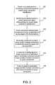
- FIG. 2is a flowchart illustrating an embodiment of a method for multiphase electrical power phase identification according to the present invention.
- FIG. 3is a flowchart illustrating in more detail an embodiment of the method for multiphase electrical power phase identification by the monitoring component according to the present invention.
- FIG. 4is a flowchart illustrating in more detail an embodiment of the method for multiphase electrical power phase identification by the power component according to the present invention.
- FIGS. 5 and 6are block diagrams illustrating an example of power phase identification according to an embodiment of the present invention.
- FIGS. 7 and 8are graphs illustrating example signal characteristics that may be found on a phase connection at the monitoring component according to the present invention.
- the present inventioncan take the form of an entirely hardware embodiment, an entirely software embodiment or an embodiment containing both hardware and software elements.
- the present inventionis implemented in software, which includes but is not limited to firmware, resident software, microcode, etc.
- the present inventioncan take the form of a computer program product accessible from a computer-usable or computer-readable medium providing program code for use by or in connection with a computer or any instruction execution system.
- a computer-usable or computer readable mediumcan be any apparatus that can contain, store, communicate, propagate, or transport the program for use by or in connection with the instruction execution system, apparatus, or device.
- the mediumcan be an electronic, magnetic, optical, electromagnetic, infrared, or semiconductor system (or apparatus or device) or a propagation medium.
- Examples of a computer-readable mediuminclude a semiconductor or solid state memory, magnetic tape, a removable computer diskette, a random access memory (RAM), a read-only memory (ROM), a rigid magnetic disk and an optical disk.
- Current examples of optical disksinclude compact disk-read only memory (CD-ROM), compact disk-read/write (CD-R/W) and DVD.
- a data processing system suitable for storing and/or executing program codewill include at least one processor coupled directly or indirectly to memory elements through a system bus.
- the memory elementscan include local memory employed during actual execution of the program code, bulk storage, and cache memories which provide temporary storage of at least some program code in order to reduce the number of times code must be retrieved from bulk storage during execution.
- I/O devicesincluding but not limited to keyboards, displays, point devices, etc.
- I/O controllersincluding but not limited to keyboards, displays, point devices, etc.
- Network adaptersmay also be coupled to the system to enable the data processing system to become coupled to other data processing systems or remote printers or storage devices through intervening private or public networks.
- Modems, cable modem and Ethernet cardsare just a few of the currently available types of network adapters.
- each block in the flowchart or block diagramsmay represent a module, segment, or portion of code, which comprises one or more executable instructions for implementing the specified local function(s).
- the functions noted in the blockmay occur out of the order noted in the figures. For example, two blocks shown in succession may, in fact, be executed substantially concurrently, or the blocks may sometimes be executed in the reverse order, depending upon the functionality involved.
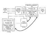
- FIG. 1illustrates an embodiment of a system for multiphase electrical power phase identification according to the present invention.
- the systemcomprises a premise with a power source 109 and a distribution panel 110 .
- the systemalso comprises a monitoring component 101 coupled between the power source 109 and the distribution panel 110 , such that any power provided by the power source 109 to the distribution panel 110 may be monitored by the monitoring component 101 .
- One or more power components 105reside throughout the premises and are connected via local power lines to the distribution panel 110 . In this embodiment, the power components 105 can either draw power from the connections or provide power to the connections.
- Sensors 111couple to the circuit connections at the distribution panel 110 and measure the voltage and current on the connections in the distribution panel 110 . Each connection provides power on one of a plurality of phases of power.
- the sensors 111there is one set of sensors per phase of power, and measurements by the sensors 111 are accessible to the monitoring component 101 .
- the sensors 111 and the monitoring component 101are illustrated here as separate components, the sensors 111 may be incorporated into the monitoring component 101 as well.
- the monitoring component 101further comprises a processor 102 and a computer readable medium 103 .
- the computer readable medium 103comprises a memory (not shown) for storing program code 104 .
- the processor 102is able to execute the program code 104 for controlling the functions of the monitoring component 101 in implementing the method of the present invention, as described further below.
- Each power component 105comprises a processor 106 and a computer readable medium 107 .
- the computer readable medium 107comprises a memory (not shown) for storing program code 108 .
- the processor 106is able to execute the program code 108 for controlling the functions of the power component 105 in implementing the method of the present invention, as described further below.
- the monitoring component 101communicates with each power component 105 over a two-way communications network (not shown), including but not limited to a direct wired network such as Ethernet, PowerLine Communications, or a wireless network.
- the processors 102 and 106 of the monitoring component 101 and power component 105may be a microcontroller, a digital signal processor (DSP), or any other suitable processor type.
- FIG. 2is a flowchart illustrating an embodiment of a method for multiphase electrical power phase identification according to the present invention.
- the power component 105sends to the monitoring component 101 a request for power phase identification ( 201 ).
- the monitoring component 101sends to the power component 105 signal characteristics for the power phase identification ( 202 ).
- the power component 105selects a phase connection at the power component 105 to identify, i.e., one of a possible plurality of power circuit phases to which the power component 105 is connected.
- the power component 105applies to this connection a signal with the characteristics received from the monitoring component 101 ( 203 ).
- the signal characteristicsmay specify a specified frequency, power level, and duration.
- the power component 105would apply a signal with the specified frequency and power level for the specified duration.
- the monitoring component 101then monitors the power levels of the phase connections at the distribution panel 110 for the signal with the characteristics ( 204 ).
- the power levelsare measured by the sensors 111 coupled to the circuits at the distribution panel 110 and analyzed by the monitoring component 101 . Assume here that the monitoring component 101 is able to find the signal with the characteristics on one of the phase connections at the distribution panel 110 .
- the monitoring component 101sends a predetermined unique identity of the phase connection at the distribution panel 110 to the power component 105 ( 205 ).
- the power component 105In response to receiving the unique identity of the phase connection at the power distribution panel 110 , the power component 105 associates this unique identity with the phase connection at the power component 105 ( 206 ). In this manner, the actual phase connection between the power component 105 and the distribution panel 110 may be ascertained and stored without a need for additional hardware or precision measurements. Further, the actual phase connections may be determined remotely and need not be ascertained at the distribution panel. The signal with the characteristics may be applied by the power component for any length of time required for the signal to be identifiable without special equipment.
- FIG. 3is a flowchart illustrating in more detail an embodiment of the method for multiphase electrical power phase identification by the monitoring component according to the present invention.
- the monitoring component 101assigns a unique identifier to each of the power components 105 ( 301 ) and establishes a data communication channel with each power component.
- the monitoring component 101monitors the power on each phase at the distribution panel 110 and assigns a unique identifier to each phase monitored.
- the monitoring component 101receives a request from a given power component 105 for power phase connection identification ( 302 ), the monitoring component 101 sends to the given power component 105 unique signal characteristics for the power phase identification ( 303 ).
- the monitoring component 101determines the unique signal characteristics based on the number of power components performing the power phase identification.
- the signal characteristicsare chosen such that the signal used by each power component may be uniquely identifiable by the monitoring component and identifiable over the normal power signal.
- the monitoring component 101receives a start indication for the power phase identification from the given power component 105 ( 304 )
- the monitoring component 101begins monitoring the phase connections at the distribution panel 110 for the unique signal characteristics sent to the given power component 105 ( 305 ).
- the monitoring component 101receives a complete indication for the power phase identification from the given power component 105 ( 306 )
- the monitoring component 101analyzes the signals received from each of the phase connections at the distribution panel 110 via the sensors 111 to determine if any contains the signal with the specified characteristics ( 307 ).
- the monitoring component 101If the monitoring component 101 is able to identify a particular connection at the distribution panel 110 with a power signal containing the signal characteristics, then the monitoring component 101 sends the unique identifier of the connection to the given power component 105 ( 310 ). If the monitoring component 101 is not able to find the signal characteristics on any of the connections at the distribution panel 110 , then the monitoring component 101 sends an error indication to the given power component 105 ( 309 ). The monitoring component 101 may then send a retry instruction to the given power component 105 .
- FIG. 4is a flowchart illustrating in more detail an embodiment of the method for multiphase electrical power phase identification by the power component according to the present invention.
- a given power component 105is connected to the local power lines and determines that it needs to identify one or more of its power phase connections.
- the given power component 105contains logic that determines when the power phase identification is to be performed based upon a predetermined set of criteria. For example, the given power component 105 may determine that the power phase identification is to be performed at first power up or when its configuration changes.
- the given power component 105sends a request to the monitoring component 101 for the power phase identification ( 401 ), via a data communication channel between the given power component 105 and the monitoring component 101 .
- the given power component 105receives from the monitoring component 101 unique signal characteristics to be used for the power phase identification ( 402 ).
- the given power component 105selects a given phase connection from among the phase connections at the given power component 105 ( 403 ) on which to perform the power phase identification.
- the given power component 105then sends a start indication to the monitoring component 101 to inform the monitoring component 101 that it is starting to apply the signal with the unique characteristics to a phase connection at the power component 105 ( 404 ).
- the given power component 105then applies the signal with the unique characteristics to the given phase connection ( 405 ). For example, assume that the signal characteristics include a specific frequency, power level, and duration.
- the given power component 105then applies on the given phase connection a signal with the specified frequency and power level for the specified duration. Upon the expiration of the specified duration, the given power component 105 ceases to apply the signal characteristics to the given phase connection and sends a complete indication to the monitoring component 101 ( 406 ) to inform the monitoring component 101 that the application of the signal has ceased.
- the monitoring component 101upon receiving the start indication, the monitoring component 101 begins to monitor the phase connections at the distribution panel 110 for the unique signal characteristics.
- the monitoring component 101proceeds to analyze the signals received from each of the phase connections at the distribution panel 110 via the sensors 111 to determine if any contains the signal with the specified characteristics.
- the given power component 105receives the unique identifier of the connection from the monitoring component 101 ( 407 ). The given power component 105 then associates the unique identifier with the given phase connection and stores the association ( 408 ). The power phase identification can be repeated for another phase connection at the given power component 105 ( 409 ). If an error indication is received from the monitoring component 101 ( 407 ), i.e., the monitoring component 101 is not able to find the signal characteristics on any of the connections at the distribution panel 110 , then the given power component 105 has the option to retry the power phase identification ( 410 ). Otherwise, the power phase identification results in an error ( 411 ).
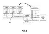
- FIGS. 5 and 6are block diagrams illustrating an example of power phase identification according to an embodiment of the present invention.
- the monitoring component 101is connected to incoming phases V 1 , V 2 , and V 3 , and assigns unique identifiers to each of the phase connections.
- single, dual, and three phase connectionsare illustrated.
- one or more power components ( 105 - 1 through 105 - 3 )are each attached to one or more phases of power but without knowledge of the actual connections at the distribution panel 110 .
- each power component ( 105 - 1 through 105 - 3 )is assigned a unique identifier by the monitoring component 101 ( 301 ).
- power component 105 - 2sends a request to the monitoring component 101 for power phase identification ( 401 ).
- the monitoring component 101receives the request from the power component 105 - 2 ( 302 ) and sends to the power component 105 - 2 unique signal characteristics for the power phase identification ( 303 ).
- the power component 105 - 2receives the unique signal characteristics from the monitoring component 101 ( 402 ) and selects a phase connection at the power component 105 - 2 ( 403 ). Assume here that the phase connection 501 is selected.
- the power component 105 - 2sends a start indication to the monitoring component 101 ( 404 ), and, as illustrated in FIG. 6 , applies a signal with the unique characteristics to the phase connection 501 ( 405 ).
- the monitoring component 101receives the start indication from the power component 105 - 2 ( 304 ) and begins monitoring all the phase connections V 1 -V 3 for the unique signal characteristics ( 305 ).
- the power component 105 - 2completes the application of the signal
- the power component 105 - 2sends a complete indication to the monitoring component 101 ( 406 ).
- the monitoring component 101analyzes the signals received on the phase connections V 1 -V 3 ( 307 ) and determines whether the unique signal characteristics were found one of the phase connections V 1 -V 3 ( 308 ).
- FIGS. 7 and 8are graphs illustrating example signal characteristics that may be found on a phase connection at the monitoring component according to the present invention.
- FIG. 7illustrates power data measured by the sensors 111 for a 2 KW load for a 4 second on/4 second off sequence over 32 seconds.
- Line 702illustrates the signal with the unique characteristics, while line 702 illustrates the normal power phase signal.
- FIG. 8illustrates a fast Fourier transform (FFT) output comparison of the power data.
- Line 801illustrates the FFT output signal with the unique characteristics, while line 802 illustrates the normal FFT output signal.
- the signal with the unique characteristicsis such that it is identifiable over the normal power phase signal.
- the monitoring component 101finds the unique signal characteristics on the phase connection V 3 .
- the monitoring component 101sends the unique identifier of the phase connection V 3 to the power component 105 - 2 ( 310 ).
- the power component 105 - 2associates the unique identifier V 3 with the phase connection 501 and stores the association ( 408 ). The above process may be repeated for other phases ( 409 ).
- a method and system for multiphase electrical power phase identificationhave been disclosed.
- the embodiments according to the present inventionprovide for the identification of the relationship between a given power connection by phase at a power component with the circuit connection at the distribution panel of a premise.
- the embodiments according to the present inventioncomprise a monitoring component operationally coupled to one or more power components.
- the power componentsplace defined sequences of load and source onto a given phase in such a fashion as to facilitate the identification of the phase in a power connection at the distribution panel by the monitoring component.
- the embodiments of the present inventionallows for more effective management and balance of power use among the power components.
Landscapes
- Engineering & Computer Science (AREA)
- Power Engineering (AREA)
- Physics & Mathematics (AREA)
- General Physics & Mathematics (AREA)
- Remote Monitoring And Control Of Power-Distribution Networks (AREA)
Abstract
Description
Claims (20)
Priority Applications (3)
| Application Number | Priority Date | Filing Date | Title |
|---|---|---|---|
| US13/340,860US8922192B2 (en) | 2011-12-30 | 2011-12-30 | Multiphase electrical power phase identification |
| PCT/US2012/071703WO2013101862A1 (en) | 2011-12-30 | 2012-12-27 | Multiphase electrical power phase identification |
| TW101151011ATW201342762A (en) | 2011-12-30 | 2012-12-28 | Multiphase electrical power phase identification |
Applications Claiming Priority (1)
| Application Number | Priority Date | Filing Date | Title |
|---|---|---|---|
| US13/340,860US8922192B2 (en) | 2011-12-30 | 2011-12-30 | Multiphase electrical power phase identification |
Publications (2)
| Publication Number | Publication Date |
|---|---|
| US20130141075A1 US20130141075A1 (en) | 2013-06-06 |
| US8922192B2true US8922192B2 (en) | 2014-12-30 |
Family
ID=47553477
Family Applications (1)
| Application Number | Title | Priority Date | Filing Date |
|---|---|---|---|
| US13/340,860Active2033-06-19US8922192B2 (en) | 2011-12-30 | 2011-12-30 | Multiphase electrical power phase identification |
Country Status (3)
| Country | Link |
|---|---|
| US (1) | US8922192B2 (en) |
| TW (1) | TW201342762A (en) |
| WO (1) | WO2013101862A1 (en) |
Families Citing this family (8)
| Publication number | Priority date | Publication date | Assignee | Title |
|---|---|---|---|---|
| US20140043015A1 (en)* | 2012-01-11 | 2014-02-13 | Harold I. Marsden | Electrical conductor phase identification system |
| US10516295B2 (en) | 2012-10-16 | 2019-12-24 | Greensmith Energy Management Systems, Inc. | System and method for group control of distributed energy storage devices |
| JP6164030B2 (en)* | 2013-10-09 | 2017-07-19 | 富士通株式会社 | Phase determination program, phase determination method, and phase determination device |
| DE102016117574A1 (en)* | 2016-09-19 | 2018-03-22 | Dr. Ing. H.C. F. Porsche Aktiengesellschaft | Method and device for managing an electricity supply through an electrical network |
| US11249122B2 (en)* | 2019-08-27 | 2022-02-15 | Vertiv Corporation | Method and apparatus for providing automated power topology mapping |
| US11381090B2 (en) | 2020-10-05 | 2022-07-05 | ATMA Energy, LLC | Systems and methods for dynamic control of distributed energy resource systems |
| DE102020130863A1 (en) | 2020-11-23 | 2022-05-25 | innogy eMobility Solutions GmbH | Method for the automated detection of a switching matrix of electrical consumables connected to a three-phase distribution network, in particular charging devices for electrical energy storage devices and charging devices |
| WO2023154394A1 (en)* | 2022-02-11 | 2023-08-17 | ENEL X Way S.r.l. | Systems and methods of phase detection and mapping for electric vehicle service equipment |
Citations (85)
| Publication number | Priority date | Publication date | Assignee | Title |
|---|---|---|---|---|
| US3487289A (en) | 1968-04-16 | 1969-12-30 | Gen Electric | Multipurpose power converter circuits |
| US4121147A (en) | 1975-01-02 | 1978-10-17 | Sangamo Electric Company | Electric meter for mounting with a standard watthour meter |
| US4287465A (en) | 1978-10-09 | 1981-09-01 | Saft-Societe Des Accumulateurs Fixes Et De Traction | Apparatus for regulating the charging of a storage battery |
| US4399396A (en) | 1981-07-22 | 1983-08-16 | Hase A M | Two level constant voltage float charge rectifier and battery surveillance apparatus |
| US4559590A (en) | 1983-03-24 | 1985-12-17 | Varian Associates, Inc. | Regulated DC to DC converter |
| US4752697A (en) | 1987-04-10 | 1988-06-21 | International Cogeneration Corporation | Cogeneration system and method |
| US4847745A (en) | 1988-11-16 | 1989-07-11 | Sundstrand Corp. | Three phase inverter power supply with balancing transformer |
| US4996637A (en) | 1988-07-20 | 1991-02-26 | Power Reflex Pty. Ltd. | Electrical converter utilizing switched uni-directional and bi-directional energy sources |
| US5262931A (en) | 1991-07-19 | 1993-11-16 | Powering, Inc. | Power converter |
| US5274571A (en) | 1991-05-20 | 1993-12-28 | The Fleming Group | Energy storage scheduling system |
| US5369353A (en) | 1992-12-08 | 1994-11-29 | Kenetech Windpower, Inc. | Controlled electrical energy storage apparatus for utility grids |
| US5510700A (en) | 1993-10-14 | 1996-04-23 | Systems Analysis And Integration, Inc. | Apparatus and method for identifying the phase of a three phase power line at a remote location |
| US5594318A (en) | 1995-04-10 | 1997-01-14 | Norvik Traction Inc. | Traction battery charging with inductive coupling |
| US5595506A (en) | 1994-11-04 | 1997-01-21 | Ekstrom Industries, Inc. | S to B watthour meter socket adapter |
| US5620337A (en) | 1995-03-15 | 1997-04-15 | Ekstrom Industries, Inc. | Fused watthour meter bypass storage adapter |
| US5909367A (en) | 1997-06-02 | 1999-06-01 | Reliance Electric Industrial Company | Modular AC-AC variable voltage and variable frequency power conveter system and control |
| US6015314A (en) | 1997-11-07 | 2000-01-18 | Colsolidated Edison Company Of New York, Inc. | Electric watt-hour meter adapter |
| US6018203A (en) | 1995-05-22 | 2000-01-25 | Target Hi-Tech Electronics Ltd. | Apparatus for and method of evenly distributing an electrical load across an n-phase power distribution network |
| US6059605A (en) | 1997-10-30 | 2000-05-09 | Ekstrom Industries, Inc. | Watthour meter socket adapter |
| US6160722A (en) | 1999-08-13 | 2000-12-12 | Powerware Corporation | Uninterruptible power supplies with dual-sourcing capability and methods of operation thereof |
| US6172480B1 (en) | 1998-10-23 | 2001-01-09 | Primetech Electronics, Inc. | Compact fast battery charger |
| US6200158B1 (en) | 1998-03-05 | 2001-03-13 | Ekstrom Industries, Inc. | Apparatus for mounting an external receptacle to a watthour meter socket adapter |
| US6268715B1 (en) | 2000-04-29 | 2001-07-31 | Motorola, Inc. | Voltage profile charge control system |
| US6310789B1 (en) | 1999-06-25 | 2001-10-30 | The Procter & Gamble Company | Dynamically-controlled, intrinsically regulated charge pump power converter |
| US20020019758A1 (en) | 2000-08-08 | 2002-02-14 | Scarpelli Peter C. | Load management dispatch system and methods |
| US6388421B2 (en) | 2000-03-24 | 2002-05-14 | Nissan Motor Co., Ltd. | Control system and control method of combined system having secondary battery and generator |
| US6404655B1 (en) | 1999-12-07 | 2002-06-11 | Semikron, Inc. | Transformerless 3 phase power inverter |
| US6420801B1 (en) | 2000-04-11 | 2002-07-16 | Electro Industries, Inc. | Alternative power supply connection |
| US6424119B1 (en) | 2001-04-19 | 2002-07-23 | American Power Conversion | Multiple energy storage device controller |
| US6429625B1 (en) | 2001-05-18 | 2002-08-06 | Palm, Inc. | Method and apparatus for indicating battery charge status |
| JP2002305842A (en) | 2001-04-03 | 2002-10-18 | Ennet Corp | Surplus power control system |
| US20020173902A1 (en) | 1999-11-30 | 2002-11-21 | Michael Haimerl | Control device for final control elements of an internal combustion engine, control unit for actuator drives of an internal combustion engine and a method for controlling an internal combustion engine |
| US20020171436A1 (en) | 2001-05-21 | 2002-11-21 | Schott Applied Power Corporation | Device for connecting parallel sources of electric power at a meter socket |
| US20020190525A1 (en) | 2001-06-18 | 2002-12-19 | Solectria Corporation | Inverter controlled, parallel connected asynchronous generator for distributed generation |
| US20030007369A1 (en) | 1998-04-02 | 2003-01-09 | Gilbreth Mark G. | Power controller |
| US6522031B2 (en) | 2000-10-10 | 2003-02-18 | American Electric Power Company, Inc. | Power load-leveling system and packet electrical storage |
| US20030057919A1 (en) | 2001-09-27 | 2003-03-27 | Tai-Her Yang | Storage/discharging device charging circuit of multi-differential source |
| US6587362B1 (en) | 2002-05-17 | 2003-07-01 | John J. Vithayathil | AC-DC converters with bi-directional thyristor valves |
| US20040062059A1 (en) | 2002-07-19 | 2004-04-01 | Ballard Power Systems Corporation | Apparatus and method employing bi-directional converter for charging and/or supplying power |
| US6750685B1 (en) | 2002-05-23 | 2004-06-15 | National Semiconductor Corporation | Apparatus and method for a bi-directional charge driver circuit |
| US20040263116A1 (en) | 2003-06-30 | 2004-12-30 | Doruk Zeynep B. | Intelligent distributed energy storage system for demand side power management |
| US20040262996A1 (en) | 2003-06-30 | 2004-12-30 | Olsen Ib Ingemann | Phase conversion device with built-in demand reduction / power boosting. |
| US20060023478A1 (en) | 2004-07-29 | 2006-02-02 | Kenji Takeda | Power conversion system |
| US7019666B2 (en) | 2002-06-10 | 2006-03-28 | Tantalus Systems Corp. | Adapter for a meter |
| US7031859B2 (en) | 2002-03-11 | 2006-04-18 | Piesinger Gregory H | Apparatus and method for identifying cable phase in a three-phase power distribution network |
| JP2006141093A (en) | 2004-11-10 | 2006-06-01 | Mitsubishi Heavy Ind Ltd | Power storage device and hybrid distributed power system |
| US20060141093A1 (en) | 2004-12-23 | 2006-06-29 | Hon Hai Precision Industry Co., Ltd. | Composite mold and method for making the same |
| US7141960B2 (en)* | 2003-06-10 | 2006-11-28 | Sagab Electronic Ab | Method and device system for testing electrical components |
| JP2006338889A (en) | 2005-05-31 | 2006-12-14 | Matsushita Electric Ind Co Ltd | Power management system and power system management method |
| US7157810B2 (en) | 2001-06-06 | 2007-01-02 | Hitachi, Ltd. | Backup power supply |
| US20070005195A1 (en) | 2005-01-10 | 2007-01-04 | Nicholas Pasquale | Distributed energy storage for reducing power demand |
| US7199527B2 (en) | 2000-11-21 | 2007-04-03 | Alien Technology Corporation | Display device and methods of manufacturing and control |
| US20070117436A1 (en) | 2005-11-21 | 2007-05-24 | The Southern Company | Meter socket bypass disconnect device |
| US20070145952A1 (en) | 2005-12-23 | 2007-06-28 | Cogeneration Energy Corp. | Efficient power system |
| US7248490B2 (en) | 2004-06-17 | 2007-07-24 | Gaia Power Technologies, Inc. | Battery and inverter configuration with increased efficiency |
| US7262694B2 (en) | 2004-06-17 | 2007-08-28 | Gaia Power Technologies, Inc. | Multifunctional, intelligent power and communication device |
| US20070200433A1 (en) | 2006-02-14 | 2007-08-30 | Matsushita Battery Industrial | Consumer-sited power management system and method |
| US20080012667A1 (en) | 2006-07-14 | 2008-01-17 | Square D Company | Method and system for time synchronized trip algorithms for breaker self protection |
| US20080141918A1 (en) | 2006-10-18 | 2008-06-19 | Mcclintock Scott G | Trailerable Sailboat with Mast Raising Method |
| JP2008141918A (en) | 2006-12-05 | 2008-06-19 | Nippon Telegr & Teleph Corp <Ntt> | Photovoltaic power generation system evaluation apparatus, method, and program |
| US20080178215A1 (en) | 2006-12-20 | 2008-07-24 | Funai Electric Co., Ltd. | Digital/analog broadcast receiver |
| JP2008178215A (en) | 2007-01-18 | 2008-07-31 | Toshiba Corp | Frequency adjustment system and frequency adjustment method |
| US20080183408A1 (en) | 2005-03-04 | 2008-07-31 | Autonetworks Technologies, Ltd. | Battery Condition Monitor |
| US20080272934A1 (en) | 2005-03-08 | 2008-11-06 | Jackson Kit Wang | Systems and Methods for Modifying Power Usage |
| TW200849770A (en) | 2007-02-27 | 2008-12-16 | Sma Solar Technology Ag | Backup power system |
| US20090102424A1 (en) | 2007-10-17 | 2009-04-23 | Jenn-Yang Tien | High reliable smart parallel energy storage tank charge/discharge management system |
| US20090146423A1 (en) | 2005-02-17 | 2009-06-11 | Mitsubishi Heavy Industries, Ltd | Power Generating System |
| US20090160259A1 (en) | 2007-12-21 | 2009-06-25 | Wi-Chi, Inc. | Distributed Energy Conversion Systems |
| EP2101403A2 (en) | 2008-03-11 | 2009-09-16 | Enphase Energy, Inc. | Apparatus for phase rotation for a three-phase AC circuit |
| US20090288896A1 (en) | 2007-02-20 | 2009-11-26 | Toyota Jidosha Kabushiki Kaisha | Hybrid vehicle |
| US20100034003A1 (en) | 2008-08-06 | 2010-02-11 | Hamilton Sundstrand Corporation | Electric Power Generation and Conversion with Controlled Magnetics |
| US20100082464A1 (en) | 2008-10-01 | 2010-04-01 | Keefe Robert A | System and Method for Managing the Consumption and Discharging of Power of Electric Vehicles |
| US20100114387A1 (en) | 2008-09-29 | 2010-05-06 | Battelle Memorial Institute | Electric power grid control using a market-based resource allocation system |
| US7747739B2 (en) | 2006-08-10 | 2010-06-29 | Gridpoint, Inc. | Connection locator in a power aggregation system for distributed electric resources |
| US20100164473A1 (en)* | 2008-12-30 | 2010-07-01 | General Electric Company | Meter phase identification |
| US7933695B2 (en) | 2007-12-07 | 2011-04-26 | Toyota Jidosha Kabushiki Kaisha | Electric vehicle power source selection |
| US20110221195A1 (en) | 2011-03-30 | 2011-09-15 | General Electric Company | System and method for power conversion |
| US8053921B2 (en) | 2007-02-13 | 2011-11-08 | Toyota Jidosha Kabushiki Kaisha | Driving force generation system, vehicle using the system, and method for controlling the system |
| US8125183B2 (en) | 2008-06-06 | 2012-02-28 | Kabushiki Kaisha Toyota Jidoshokki | Charging system and vehicle and charge controller for the charging system |
| US20120069619A1 (en) | 2006-12-07 | 2012-03-22 | Northern Power Systems, Inc. | Modular Power Converters Usable Alone or In A Multiphase Power Converter |
| US8149114B2 (en) | 2010-02-09 | 2012-04-03 | Ekstrom Industries, Inc. | Utility meter tamper monitoring system and method |
| EP2475059A1 (en) | 2011-01-10 | 2012-07-11 | General Electric Company | Load balancing for distribution power supply system |
| US20120319748A1 (en) | 2011-06-14 | 2012-12-20 | GLOBALFOUDRIES Singapore Pte. Ltd. | Digital phase locked loop system and method |
| US20130030588A1 (en) | 2011-12-29 | 2013-01-31 | Powergetics, Inc. | Multiphase Electrical Power Construction and Assignment at Minimal Loss |
| US8712711B2 (en)* | 2011-07-21 | 2014-04-29 | Cisco Technology, Inc. | Identification of electrical grid phase information for end-points in a grid network |
- 2011
- 2011-12-30USUS13/340,860patent/US8922192B2/enactiveActive
- 2012
- 2012-12-27WOPCT/US2012/071703patent/WO2013101862A1/enactiveApplication Filing
- 2012-12-28TWTW101151011Apatent/TW201342762A/enunknown
Patent Citations (95)
| Publication number | Priority date | Publication date | Assignee | Title |
|---|---|---|---|---|
| US3487289A (en) | 1968-04-16 | 1969-12-30 | Gen Electric | Multipurpose power converter circuits |
| US4121147A (en) | 1975-01-02 | 1978-10-17 | Sangamo Electric Company | Electric meter for mounting with a standard watthour meter |
| US4287465A (en) | 1978-10-09 | 1981-09-01 | Saft-Societe Des Accumulateurs Fixes Et De Traction | Apparatus for regulating the charging of a storage battery |
| US4399396A (en) | 1981-07-22 | 1983-08-16 | Hase A M | Two level constant voltage float charge rectifier and battery surveillance apparatus |
| US4559590A (en) | 1983-03-24 | 1985-12-17 | Varian Associates, Inc. | Regulated DC to DC converter |
| US4752697A (en) | 1987-04-10 | 1988-06-21 | International Cogeneration Corporation | Cogeneration system and method |
| US4996637A (en) | 1988-07-20 | 1991-02-26 | Power Reflex Pty. Ltd. | Electrical converter utilizing switched uni-directional and bi-directional energy sources |
| US4847745A (en) | 1988-11-16 | 1989-07-11 | Sundstrand Corp. | Three phase inverter power supply with balancing transformer |
| US5274571A (en) | 1991-05-20 | 1993-12-28 | The Fleming Group | Energy storage scheduling system |
| US5262931A (en) | 1991-07-19 | 1993-11-16 | Powering, Inc. | Power converter |
| US5369353A (en) | 1992-12-08 | 1994-11-29 | Kenetech Windpower, Inc. | Controlled electrical energy storage apparatus for utility grids |
| US5510700A (en) | 1993-10-14 | 1996-04-23 | Systems Analysis And Integration, Inc. | Apparatus and method for identifying the phase of a three phase power line at a remote location |
| US5595506A (en) | 1994-11-04 | 1997-01-21 | Ekstrom Industries, Inc. | S to B watthour meter socket adapter |
| US5620337A (en) | 1995-03-15 | 1997-04-15 | Ekstrom Industries, Inc. | Fused watthour meter bypass storage adapter |
| US5594318A (en) | 1995-04-10 | 1997-01-14 | Norvik Traction Inc. | Traction battery charging with inductive coupling |
| US6018203A (en) | 1995-05-22 | 2000-01-25 | Target Hi-Tech Electronics Ltd. | Apparatus for and method of evenly distributing an electrical load across an n-phase power distribution network |
| US5909367A (en) | 1997-06-02 | 1999-06-01 | Reliance Electric Industrial Company | Modular AC-AC variable voltage and variable frequency power conveter system and control |
| US6059605A (en) | 1997-10-30 | 2000-05-09 | Ekstrom Industries, Inc. | Watthour meter socket adapter |
| US6015314A (en) | 1997-11-07 | 2000-01-18 | Colsolidated Edison Company Of New York, Inc. | Electric watt-hour meter adapter |
| US6200158B1 (en) | 1998-03-05 | 2001-03-13 | Ekstrom Industries, Inc. | Apparatus for mounting an external receptacle to a watthour meter socket adapter |
| US20030007369A1 (en) | 1998-04-02 | 2003-01-09 | Gilbreth Mark G. | Power controller |
| US6172480B1 (en) | 1998-10-23 | 2001-01-09 | Primetech Electronics, Inc. | Compact fast battery charger |
| US6301132B1 (en) | 1998-10-23 | 2001-10-09 | Primetech Electronics, Inc. | Compact fast battery charger |
| US6310789B1 (en) | 1999-06-25 | 2001-10-30 | The Procter & Gamble Company | Dynamically-controlled, intrinsically regulated charge pump power converter |
| US6160722A (en) | 1999-08-13 | 2000-12-12 | Powerware Corporation | Uninterruptible power supplies with dual-sourcing capability and methods of operation thereof |
| US20020173902A1 (en) | 1999-11-30 | 2002-11-21 | Michael Haimerl | Control device for final control elements of an internal combustion engine, control unit for actuator drives of an internal combustion engine and a method for controlling an internal combustion engine |
| US6606552B2 (en) | 1999-11-30 | 2003-08-12 | Siemens Aktiengesellschaft | Control device for final control elements of an internal combustion engine, control unit for actuator drives of an internal combustion engine and a method for controlling an internal combustion engine |
| US6404655B1 (en) | 1999-12-07 | 2002-06-11 | Semikron, Inc. | Transformerless 3 phase power inverter |
| US6388421B2 (en) | 2000-03-24 | 2002-05-14 | Nissan Motor Co., Ltd. | Control system and control method of combined system having secondary battery and generator |
| US6420801B1 (en) | 2000-04-11 | 2002-07-16 | Electro Industries, Inc. | Alternative power supply connection |
| US6268715B1 (en) | 2000-04-29 | 2001-07-31 | Motorola, Inc. | Voltage profile charge control system |
| US20020019758A1 (en) | 2000-08-08 | 2002-02-14 | Scarpelli Peter C. | Load management dispatch system and methods |
| US6522031B2 (en) | 2000-10-10 | 2003-02-18 | American Electric Power Company, Inc. | Power load-leveling system and packet electrical storage |
| US7199527B2 (en) | 2000-11-21 | 2007-04-03 | Alien Technology Corporation | Display device and methods of manufacturing and control |
| JP2002305842A (en) | 2001-04-03 | 2002-10-18 | Ennet Corp | Surplus power control system |
| US6639383B2 (en) | 2001-04-19 | 2003-10-28 | American Power Conversion | Multiple energy storage device controller |
| US6424119B1 (en) | 2001-04-19 | 2002-07-23 | American Power Conversion | Multiple energy storage device controller |
| US6429625B1 (en) | 2001-05-18 | 2002-08-06 | Palm, Inc. | Method and apparatus for indicating battery charge status |
| US20020171436A1 (en) | 2001-05-21 | 2002-11-21 | Schott Applied Power Corporation | Device for connecting parallel sources of electric power at a meter socket |
| US7157810B2 (en) | 2001-06-06 | 2007-01-02 | Hitachi, Ltd. | Backup power supply |
| US20020190525A1 (en) | 2001-06-18 | 2002-12-19 | Solectria Corporation | Inverter controlled, parallel connected asynchronous generator for distributed generation |
| US20030057919A1 (en) | 2001-09-27 | 2003-03-27 | Tai-Her Yang | Storage/discharging device charging circuit of multi-differential source |
| US7031859B2 (en) | 2002-03-11 | 2006-04-18 | Piesinger Gregory H | Apparatus and method for identifying cable phase in a three-phase power distribution network |
| US6587362B1 (en) | 2002-05-17 | 2003-07-01 | John J. Vithayathil | AC-DC converters with bi-directional thyristor valves |
| US6750685B1 (en) | 2002-05-23 | 2004-06-15 | National Semiconductor Corporation | Apparatus and method for a bi-directional charge driver circuit |
| US7019666B2 (en) | 2002-06-10 | 2006-03-28 | Tantalus Systems Corp. | Adapter for a meter |
| US20040062059A1 (en) | 2002-07-19 | 2004-04-01 | Ballard Power Systems Corporation | Apparatus and method employing bi-directional converter for charging and/or supplying power |
| US7141960B2 (en)* | 2003-06-10 | 2006-11-28 | Sagab Electronic Ab | Method and device system for testing electrical components |
| US20040262996A1 (en) | 2003-06-30 | 2004-12-30 | Olsen Ib Ingemann | Phase conversion device with built-in demand reduction / power boosting. |
| US7385373B2 (en) | 2003-06-30 | 2008-06-10 | Gaia Power Technologies, Inc. | Intelligent distributed energy storage system for demand side power management |
| US20040263116A1 (en) | 2003-06-30 | 2004-12-30 | Doruk Zeynep B. | Intelligent distributed energy storage system for demand side power management |
| US7262694B2 (en) | 2004-06-17 | 2007-08-28 | Gaia Power Technologies, Inc. | Multifunctional, intelligent power and communication device |
| US7248490B2 (en) | 2004-06-17 | 2007-07-24 | Gaia Power Technologies, Inc. | Battery and inverter configuration with increased efficiency |
| US20060023478A1 (en) | 2004-07-29 | 2006-02-02 | Kenji Takeda | Power conversion system |
| US7456519B2 (en) | 2004-07-29 | 2008-11-25 | Hitachi, Ltd. | Power conversion system |
| JP2006141093A (en) | 2004-11-10 | 2006-06-01 | Mitsubishi Heavy Ind Ltd | Power storage device and hybrid distributed power system |
| US20060141093A1 (en) | 2004-12-23 | 2006-06-29 | Hon Hai Precision Industry Co., Ltd. | Composite mold and method for making the same |
| US20070005195A1 (en) | 2005-01-10 | 2007-01-04 | Nicholas Pasquale | Distributed energy storage for reducing power demand |
| US7804183B2 (en) | 2005-02-17 | 2010-09-28 | Mitsubishi Heavy Industries, Ltd. | Power generating system |
| US20090146423A1 (en) | 2005-02-17 | 2009-06-11 | Mitsubishi Heavy Industries, Ltd | Power Generating System |
| US20080183408A1 (en) | 2005-03-04 | 2008-07-31 | Autonetworks Technologies, Ltd. | Battery Condition Monitor |
| US7676334B2 (en) | 2005-03-04 | 2010-03-09 | Autonetworks Technologies, Ltd. | Battery condition monitor |
| US8183995B2 (en) | 2005-03-08 | 2012-05-22 | Jackson Kit Wang | Systems and methods for modifying power usage |
| US20080272934A1 (en) | 2005-03-08 | 2008-11-06 | Jackson Kit Wang | Systems and Methods for Modifying Power Usage |
| JP2006338889A (en) | 2005-05-31 | 2006-12-14 | Matsushita Electric Ind Co Ltd | Power management system and power system management method |
| US20070117436A1 (en) | 2005-11-21 | 2007-05-24 | The Southern Company | Meter socket bypass disconnect device |
| US20070145952A1 (en) | 2005-12-23 | 2007-06-28 | Cogeneration Energy Corp. | Efficient power system |
| US20070200433A1 (en) | 2006-02-14 | 2007-08-30 | Matsushita Battery Industrial | Consumer-sited power management system and method |
| US7752145B2 (en) | 2006-02-14 | 2010-07-06 | Panasonic Corporation | Consumer-sited power management system and method |
| US20080012667A1 (en) | 2006-07-14 | 2008-01-17 | Square D Company | Method and system for time synchronized trip algorithms for breaker self protection |
| US7747739B2 (en) | 2006-08-10 | 2010-06-29 | Gridpoint, Inc. | Connection locator in a power aggregation system for distributed electric resources |
| US20080141918A1 (en) | 2006-10-18 | 2008-06-19 | Mcclintock Scott G | Trailerable Sailboat with Mast Raising Method |
| JP2008141918A (en) | 2006-12-05 | 2008-06-19 | Nippon Telegr & Teleph Corp <Ntt> | Photovoltaic power generation system evaluation apparatus, method, and program |
| US20120069619A1 (en) | 2006-12-07 | 2012-03-22 | Northern Power Systems, Inc. | Modular Power Converters Usable Alone or In A Multiphase Power Converter |
| US20080178215A1 (en) | 2006-12-20 | 2008-07-24 | Funai Electric Co., Ltd. | Digital/analog broadcast receiver |
| JP2008178215A (en) | 2007-01-18 | 2008-07-31 | Toshiba Corp | Frequency adjustment system and frequency adjustment method |
| US8053921B2 (en) | 2007-02-13 | 2011-11-08 | Toyota Jidosha Kabushiki Kaisha | Driving force generation system, vehicle using the system, and method for controlling the system |
| US20090288896A1 (en) | 2007-02-20 | 2009-11-26 | Toyota Jidosha Kabushiki Kaisha | Hybrid vehicle |
| TW200849770A (en) | 2007-02-27 | 2008-12-16 | Sma Solar Technology Ag | Backup power system |
| US20090102424A1 (en) | 2007-10-17 | 2009-04-23 | Jenn-Yang Tien | High reliable smart parallel energy storage tank charge/discharge management system |
| US7933695B2 (en) | 2007-12-07 | 2011-04-26 | Toyota Jidosha Kabushiki Kaisha | Electric vehicle power source selection |
| US20090160259A1 (en) | 2007-12-21 | 2009-06-25 | Wi-Chi, Inc. | Distributed Energy Conversion Systems |
| EP2101403A2 (en) | 2008-03-11 | 2009-09-16 | Enphase Energy, Inc. | Apparatus for phase rotation for a three-phase AC circuit |
| US8125183B2 (en) | 2008-06-06 | 2012-02-28 | Kabushiki Kaisha Toyota Jidoshokki | Charging system and vehicle and charge controller for the charging system |
| US20100034003A1 (en) | 2008-08-06 | 2010-02-11 | Hamilton Sundstrand Corporation | Electric Power Generation and Conversion with Controlled Magnetics |
| US20100114387A1 (en) | 2008-09-29 | 2010-05-06 | Battelle Memorial Institute | Electric power grid control using a market-based resource allocation system |
| US20100082464A1 (en) | 2008-10-01 | 2010-04-01 | Keefe Robert A | System and Method for Managing the Consumption and Discharging of Power of Electric Vehicles |
| US20100164473A1 (en)* | 2008-12-30 | 2010-07-01 | General Electric Company | Meter phase identification |
| EP2204658A1 (en) | 2008-12-30 | 2010-07-07 | General Electric Company | Meter phase identification |
| US8149114B2 (en) | 2010-02-09 | 2012-04-03 | Ekstrom Industries, Inc. | Utility meter tamper monitoring system and method |
| EP2475059A1 (en) | 2011-01-10 | 2012-07-11 | General Electric Company | Load balancing for distribution power supply system |
| US20110221195A1 (en) | 2011-03-30 | 2011-09-15 | General Electric Company | System and method for power conversion |
| US20120319748A1 (en) | 2011-06-14 | 2012-12-20 | GLOBALFOUDRIES Singapore Pte. Ltd. | Digital phase locked loop system and method |
| US8712711B2 (en)* | 2011-07-21 | 2014-04-29 | Cisco Technology, Inc. | Identification of electrical grid phase information for end-points in a grid network |
| US20130030588A1 (en) | 2011-12-29 | 2013-01-31 | Powergetics, Inc. | Multiphase Electrical Power Construction and Assignment at Minimal Loss |
Non-Patent Citations (5)
| Title |
|---|
| Cha et al. "A New Soft Switching Direct Converter for Residential Fuel Cell Power System", IAS 2004. 2:1172-1177. |
| Chenier, Glen. Reversal of Fortune. Electronic, Design, Strategy, News. 2009. p. 62. |
| Choe et al. "A Parallel Operation Algorithm with Power-Sharing Technique for FC Generation Systems". 2009.725-731. |
| International Search Report, PCT/US2012/071703 dated May 14, 2013. |
| M.A. Kai, "Lessons Learned from the Texas Synchrophasor Network", IEEE-PES Innovative Smart Grid Technologies Conference, Berlin, Oct. 14-17, 2012. |
Also Published As
| Publication number | Publication date |
|---|---|
| WO2013101862A1 (en) | 2013-07-04 |
| US20130141075A1 (en) | 2013-06-06 |
| TW201342762A (en) | 2013-10-16 |
Similar Documents
| Publication | Publication Date | Title |
|---|---|---|
| US8922192B2 (en) | Multiphase electrical power phase identification | |
| US10901489B2 (en) | Multiphase electrical power construction and assignment at minimal loss | |
| US8464080B2 (en) | Managing server power consumption in a data center | |
| US8630822B2 (en) | Data center design tool | |
| US8803570B2 (en) | Multiphase electrical power assignment at minimal loss | |
| US8683251B2 (en) | Determining redundancy of power feeds connecting a server to a power supply | |
| EP2489987B1 (en) | Non-invasive energy consumption monitoring | |
| US20130282188A1 (en) | Centralized control center for electrical network computational services | |
| US20230356615A1 (en) | Method and system for allocating charging resources to electric vehicles | |
| US9647458B2 (en) | Distributed phase balancing | |
| CN105372496B (en) | Phase identification device and method in supply network | |
| US20210003307A1 (en) | Communication Implementation Method and Device for Air Conditioning Units, Non-Transitory Computer Readable Storage Medium and Processor | |
| US20190363638A1 (en) | Balancing power distribution | |
| US9794651B2 (en) | Systems and methods for profiling of hardware components of computing devices | |
| CN115051912B (en) | Power failure user positioning method, device, equipment and medium | |
| JP2016075492A (en) | Connection relationship determination system and connection relationship determination method | |
| US11977426B2 (en) | Control apparatus, control method and program | |
| CN115831813A (en) | Method, device, equipment and medium for selecting wafer test batches | |
| WO2015176440A1 (en) | Method and device for monitoring module acquisition of usage scenario of power supply module | |
| BR102012000746A2 (en) | ENERGY SYSTEM AND METER | |
| WO2017150140A1 (en) | Terminal device, control device, server, evaluation method, and program | |
| JP6202227B1 (en) | Distribution phase management support system | |
| JP6417671B2 (en) | Electronic device, noise suppression system, and noise suppression method | |
| de Souza et al. | Application of integrated linear programming models for the planning of distribution networks | |
| JP2017022564A (en) | Device control device and device control program |
Legal Events
| Date | Code | Title | Description |
|---|---|---|---|
| AS | Assignment | Owner name:POWERGETICS, INC., CALIFORNIA Free format text:ASSIGNMENT OF ASSIGNORS INTEREST;ASSIGNORS:ERHART, DAVID;SOUTHEREN, CRAIG;REEL/FRAME:027840/0978 Effective date:20120113 | |
| AS | Assignment | Owner name:POWERGETICS, INC., CALIFORNIA Free format text:ASSIGNMENT OF ASSIGNORS INTEREST;ASSIGNOR:REINECCIUS, STACEY;REEL/FRAME:029843/0982 Effective date:20130212 | |
| AS | Assignment | Owner name:STEM, INC, CALIFORNIA Free format text:CHANGE OF NAME;ASSIGNOR:POWERGETICS, INC.;REEL/FRAME:029856/0505 Effective date:20120409 | |
| STCF | Information on status: patent grant | Free format text:PATENTED CASE | |
| MAFP | Maintenance fee payment | Free format text:PAYMENT OF MAINTENANCE FEE, 4TH YR, SMALL ENTITY (ORIGINAL EVENT CODE: M2551) Year of fee payment:4 | |
| AS | Assignment | Owner name:GENERATE LENDING, LLC, CALIFORNIA Free format text:SECURITY INTEREST;ASSIGNOR:STEM, INC.;REEL/FRAME:051629/0400 Effective date:20191230 | |
| AS | Assignment | Owner name:ARES CLIMATE INFRASTRUCTURE PARTNERS, L.P., AS ADMINISTRATIVE AGENT, NEW YORK Free format text:SECURITY INTEREST;ASSIGNOR:STEM, INC.;REEL/FRAME:052677/0027 Effective date:20200515 | |
| AS | Assignment | Owner name:STEM, INC., CALIFORNIA Free format text:RELEASE OF PATENT SECURITY AGREEMENT RECORDED AT REEL 052677/FRAME 0027;ASSIGNOR:ARES CLIMATE INFRASTRUCTURE PARTNERS, L.P.;REEL/FRAME:056079/0736 Effective date:20210428 | |
| AS | Assignment | Owner name:STEM, INC., CALIFORNIA Free format text:RELEASE OF INTELLECTUAL PROPERTY SECURITY INTEREST RECORDED AT REEL 051629/FRAME 0400;ASSIGNOR:GENERATE LENDING, LLC;REEL/FRAME:056121/0527 Effective date:20210428 | |
| MAFP | Maintenance fee payment | Free format text:PAYMENT OF MAINTENANCE FEE, 8TH YR, SMALL ENTITY (ORIGINAL EVENT CODE: M2552); ENTITY STATUS OF PATENT OWNER: SMALL ENTITY Year of fee payment:8 | |
| AS | Assignment | Owner name:U.S. BANK TRUST COMPANY, NATIONAL ASSOCIATION, CONNECTICUT Free format text:SECURITY INTEREST;ASSIGNOR:STEM, INC.;REEL/FRAME:071569/0935 Effective date:20250630 |