US8922057B2 - System for multiple energy storage and management and method of making same - Google Patents
System for multiple energy storage and management and method of making sameDownload PDFInfo
- Publication number
- US8922057B2 US8922057B2US13/224,669US201113224669AUS8922057B2US 8922057 B2US8922057 B2US 8922057B2US 201113224669 AUS201113224669 AUS 201113224669AUS 8922057 B2US8922057 B2US 8922057B2
- Authority
- US
- United States
- Prior art keywords
- energy storage
- storage system
- energy
- boost converter
- coupled
- Prior art date
- Legal status (The legal status is an assumption and is not a legal conclusion. Google has not performed a legal analysis and makes no representation as to the accuracy of the status listed.)
- Active, expires
Links
Images


Classifications
- B60L11/1861—
- B60L11/005—
- B60L11/1803—
- B60L11/1816—
- B60L11/1868—
- B—PERFORMING OPERATIONS; TRANSPORTING
- B60—VEHICLES IN GENERAL
- B60L—PROPULSION OF ELECTRICALLY-PROPELLED VEHICLES; SUPPLYING ELECTRIC POWER FOR AUXILIARY EQUIPMENT OF ELECTRICALLY-PROPELLED VEHICLES; ELECTRODYNAMIC BRAKE SYSTEMS FOR VEHICLES IN GENERAL; MAGNETIC SUSPENSION OR LEVITATION FOR VEHICLES; MONITORING OPERATING VARIABLES OF ELECTRICALLY-PROPELLED VEHICLES; ELECTRIC SAFETY DEVICES FOR ELECTRICALLY-PROPELLED VEHICLES
- B60L3/00—Electric devices on electrically-propelled vehicles for safety purposes; Monitoring operating variables, e.g. speed, deceleration or energy consumption
- B60L3/0023—Detecting, eliminating, remedying or compensating for drive train abnormalities, e.g. failures within the drive train
- B60L3/0046—Detecting, eliminating, remedying or compensating for drive train abnormalities, e.g. failures within the drive train relating to electric energy storage systems, e.g. batteries or capacitors
- B—PERFORMING OPERATIONS; TRANSPORTING
- B60—VEHICLES IN GENERAL
- B60L—PROPULSION OF ELECTRICALLY-PROPELLED VEHICLES; SUPPLYING ELECTRIC POWER FOR AUXILIARY EQUIPMENT OF ELECTRICALLY-PROPELLED VEHICLES; ELECTRODYNAMIC BRAKE SYSTEMS FOR VEHICLES IN GENERAL; MAGNETIC SUSPENSION OR LEVITATION FOR VEHICLES; MONITORING OPERATING VARIABLES OF ELECTRICALLY-PROPELLED VEHICLES; ELECTRIC SAFETY DEVICES FOR ELECTRICALLY-PROPELLED VEHICLES
- B60L3/00—Electric devices on electrically-propelled vehicles for safety purposes; Monitoring operating variables, e.g. speed, deceleration or energy consumption
- B60L3/0023—Detecting, eliminating, remedying or compensating for drive train abnormalities, e.g. failures within the drive train
- B60L3/0069—Detecting, eliminating, remedying or compensating for drive train abnormalities, e.g. failures within the drive train relating to the isolation, e.g. ground fault or leak current
- B—PERFORMING OPERATIONS; TRANSPORTING
- B60—VEHICLES IN GENERAL
- B60L—PROPULSION OF ELECTRICALLY-PROPELLED VEHICLES; SUPPLYING ELECTRIC POWER FOR AUXILIARY EQUIPMENT OF ELECTRICALLY-PROPELLED VEHICLES; ELECTRODYNAMIC BRAKE SYSTEMS FOR VEHICLES IN GENERAL; MAGNETIC SUSPENSION OR LEVITATION FOR VEHICLES; MONITORING OPERATING VARIABLES OF ELECTRICALLY-PROPELLED VEHICLES; ELECTRIC SAFETY DEVICES FOR ELECTRICALLY-PROPELLED VEHICLES
- B60L3/00—Electric devices on electrically-propelled vehicles for safety purposes; Monitoring operating variables, e.g. speed, deceleration or energy consumption
- B60L3/04—Cutting off the power supply under fault conditions
- B—PERFORMING OPERATIONS; TRANSPORTING
- B60—VEHICLES IN GENERAL
- B60L—PROPULSION OF ELECTRICALLY-PROPELLED VEHICLES; SUPPLYING ELECTRIC POWER FOR AUXILIARY EQUIPMENT OF ELECTRICALLY-PROPELLED VEHICLES; ELECTRODYNAMIC BRAKE SYSTEMS FOR VEHICLES IN GENERAL; MAGNETIC SUSPENSION OR LEVITATION FOR VEHICLES; MONITORING OPERATING VARIABLES OF ELECTRICALLY-PROPELLED VEHICLES; ELECTRIC SAFETY DEVICES FOR ELECTRICALLY-PROPELLED VEHICLES
- B60L50/00—Electric propulsion with power supplied within the vehicle
- B60L50/40—Electric propulsion with power supplied within the vehicle using propulsion power supplied by capacitors
- B—PERFORMING OPERATIONS; TRANSPORTING
- B60—VEHICLES IN GENERAL
- B60L—PROPULSION OF ELECTRICALLY-PROPELLED VEHICLES; SUPPLYING ELECTRIC POWER FOR AUXILIARY EQUIPMENT OF ELECTRICALLY-PROPELLED VEHICLES; ELECTRODYNAMIC BRAKE SYSTEMS FOR VEHICLES IN GENERAL; MAGNETIC SUSPENSION OR LEVITATION FOR VEHICLES; MONITORING OPERATING VARIABLES OF ELECTRICALLY-PROPELLED VEHICLES; ELECTRIC SAFETY DEVICES FOR ELECTRICALLY-PROPELLED VEHICLES
- B60L50/00—Electric propulsion with power supplied within the vehicle
- B60L50/50—Electric propulsion with power supplied within the vehicle using propulsion power supplied by batteries or fuel cells
- B60L50/51—Electric propulsion with power supplied within the vehicle using propulsion power supplied by batteries or fuel cells characterised by AC-motors
- B—PERFORMING OPERATIONS; TRANSPORTING
- B60—VEHICLES IN GENERAL
- B60L—PROPULSION OF ELECTRICALLY-PROPELLED VEHICLES; SUPPLYING ELECTRIC POWER FOR AUXILIARY EQUIPMENT OF ELECTRICALLY-PROPELLED VEHICLES; ELECTRODYNAMIC BRAKE SYSTEMS FOR VEHICLES IN GENERAL; MAGNETIC SUSPENSION OR LEVITATION FOR VEHICLES; MONITORING OPERATING VARIABLES OF ELECTRICALLY-PROPELLED VEHICLES; ELECTRIC SAFETY DEVICES FOR ELECTRICALLY-PROPELLED VEHICLES
- B60L53/00—Methods of charging batteries, specially adapted for electric vehicles; Charging stations or on-board charging equipment therefor; Exchange of energy storage elements in electric vehicles
- B60L53/10—Methods of charging batteries, specially adapted for electric vehicles; Charging stations or on-board charging equipment therefor; Exchange of energy storage elements in electric vehicles characterised by the energy transfer between the charging station and the vehicle
- B60L53/14—Conductive energy transfer
- B—PERFORMING OPERATIONS; TRANSPORTING
- B60—VEHICLES IN GENERAL
- B60L—PROPULSION OF ELECTRICALLY-PROPELLED VEHICLES; SUPPLYING ELECTRIC POWER FOR AUXILIARY EQUIPMENT OF ELECTRICALLY-PROPELLED VEHICLES; ELECTRODYNAMIC BRAKE SYSTEMS FOR VEHICLES IN GENERAL; MAGNETIC SUSPENSION OR LEVITATION FOR VEHICLES; MONITORING OPERATING VARIABLES OF ELECTRICALLY-PROPELLED VEHICLES; ELECTRIC SAFETY DEVICES FOR ELECTRICALLY-PROPELLED VEHICLES
- B60L58/00—Methods or circuit arrangements for monitoring or controlling batteries or fuel cells, specially adapted for electric vehicles
- B60L58/10—Methods or circuit arrangements for monitoring or controlling batteries or fuel cells, specially adapted for electric vehicles for monitoring or controlling batteries
- B60L58/12—Methods or circuit arrangements for monitoring or controlling batteries or fuel cells, specially adapted for electric vehicles for monitoring or controlling batteries responding to state of charge [SoC]
- B—PERFORMING OPERATIONS; TRANSPORTING
- B60—VEHICLES IN GENERAL
- B60L—PROPULSION OF ELECTRICALLY-PROPELLED VEHICLES; SUPPLYING ELECTRIC POWER FOR AUXILIARY EQUIPMENT OF ELECTRICALLY-PROPELLED VEHICLES; ELECTRODYNAMIC BRAKE SYSTEMS FOR VEHICLES IN GENERAL; MAGNETIC SUSPENSION OR LEVITATION FOR VEHICLES; MONITORING OPERATING VARIABLES OF ELECTRICALLY-PROPELLED VEHICLES; ELECTRIC SAFETY DEVICES FOR ELECTRICALLY-PROPELLED VEHICLES
- B60L58/00—Methods or circuit arrangements for monitoring or controlling batteries or fuel cells, specially adapted for electric vehicles
- B60L58/10—Methods or circuit arrangements for monitoring or controlling batteries or fuel cells, specially adapted for electric vehicles for monitoring or controlling batteries
- B60L58/16—Methods or circuit arrangements for monitoring or controlling batteries or fuel cells, specially adapted for electric vehicles for monitoring or controlling batteries responding to battery ageing, e.g. to the number of charging cycles or the state of health [SoH]
- B—PERFORMING OPERATIONS; TRANSPORTING
- B60—VEHICLES IN GENERAL
- B60L—PROPULSION OF ELECTRICALLY-PROPELLED VEHICLES; SUPPLYING ELECTRIC POWER FOR AUXILIARY EQUIPMENT OF ELECTRICALLY-PROPELLED VEHICLES; ELECTRODYNAMIC BRAKE SYSTEMS FOR VEHICLES IN GENERAL; MAGNETIC SUSPENSION OR LEVITATION FOR VEHICLES; MONITORING OPERATING VARIABLES OF ELECTRICALLY-PROPELLED VEHICLES; ELECTRIC SAFETY DEVICES FOR ELECTRICALLY-PROPELLED VEHICLES
- B60L58/00—Methods or circuit arrangements for monitoring or controlling batteries or fuel cells, specially adapted for electric vehicles
- B60L58/10—Methods or circuit arrangements for monitoring or controlling batteries or fuel cells, specially adapted for electric vehicles for monitoring or controlling batteries
- B60L58/18—Methods or circuit arrangements for monitoring or controlling batteries or fuel cells, specially adapted for electric vehicles for monitoring or controlling batteries of two or more battery modules
- B60L58/20—Methods or circuit arrangements for monitoring or controlling batteries or fuel cells, specially adapted for electric vehicles for monitoring or controlling batteries of two or more battery modules having different nominal voltages
- B—PERFORMING OPERATIONS; TRANSPORTING
- B60—VEHICLES IN GENERAL
- B60L—PROPULSION OF ELECTRICALLY-PROPELLED VEHICLES; SUPPLYING ELECTRIC POWER FOR AUXILIARY EQUIPMENT OF ELECTRICALLY-PROPELLED VEHICLES; ELECTRODYNAMIC BRAKE SYSTEMS FOR VEHICLES IN GENERAL; MAGNETIC SUSPENSION OR LEVITATION FOR VEHICLES; MONITORING OPERATING VARIABLES OF ELECTRICALLY-PROPELLED VEHICLES; ELECTRIC SAFETY DEVICES FOR ELECTRICALLY-PROPELLED VEHICLES
- B60L58/00—Methods or circuit arrangements for monitoring or controlling batteries or fuel cells, specially adapted for electric vehicles
- B60L58/10—Methods or circuit arrangements for monitoring or controlling batteries or fuel cells, specially adapted for electric vehicles for monitoring or controlling batteries
- B60L58/24—Methods or circuit arrangements for monitoring or controlling batteries or fuel cells, specially adapted for electric vehicles for monitoring or controlling batteries for controlling the temperature of batteries
- B—PERFORMING OPERATIONS; TRANSPORTING
- B60—VEHICLES IN GENERAL
- B60L—PROPULSION OF ELECTRICALLY-PROPELLED VEHICLES; SUPPLYING ELECTRIC POWER FOR AUXILIARY EQUIPMENT OF ELECTRICALLY-PROPELLED VEHICLES; ELECTRODYNAMIC BRAKE SYSTEMS FOR VEHICLES IN GENERAL; MAGNETIC SUSPENSION OR LEVITATION FOR VEHICLES; MONITORING OPERATING VARIABLES OF ELECTRICALLY-PROPELLED VEHICLES; ELECTRIC SAFETY DEVICES FOR ELECTRICALLY-PROPELLED VEHICLES
- B60L2200/00—Type of vehicles
- B60L2200/26—Rail vehicles
- B—PERFORMING OPERATIONS; TRANSPORTING
- B60—VEHICLES IN GENERAL
- B60L—PROPULSION OF ELECTRICALLY-PROPELLED VEHICLES; SUPPLYING ELECTRIC POWER FOR AUXILIARY EQUIPMENT OF ELECTRICALLY-PROPELLED VEHICLES; ELECTRODYNAMIC BRAKE SYSTEMS FOR VEHICLES IN GENERAL; MAGNETIC SUSPENSION OR LEVITATION FOR VEHICLES; MONITORING OPERATING VARIABLES OF ELECTRICALLY-PROPELLED VEHICLES; ELECTRIC SAFETY DEVICES FOR ELECTRICALLY-PROPELLED VEHICLES
- B60L2210/00—Converter types
- B60L2210/10—DC to DC converters
- B60L2210/14—Boost converters
- B—PERFORMING OPERATIONS; TRANSPORTING
- B60—VEHICLES IN GENERAL
- B60L—PROPULSION OF ELECTRICALLY-PROPELLED VEHICLES; SUPPLYING ELECTRIC POWER FOR AUXILIARY EQUIPMENT OF ELECTRICALLY-PROPELLED VEHICLES; ELECTRODYNAMIC BRAKE SYSTEMS FOR VEHICLES IN GENERAL; MAGNETIC SUSPENSION OR LEVITATION FOR VEHICLES; MONITORING OPERATING VARIABLES OF ELECTRICALLY-PROPELLED VEHICLES; ELECTRIC SAFETY DEVICES FOR ELECTRICALLY-PROPELLED VEHICLES
- B60L2240/00—Control parameters of input or output; Target parameters
- B60L2240/10—Vehicle control parameters
- B60L2240/12—Speed
- B—PERFORMING OPERATIONS; TRANSPORTING
- B60—VEHICLES IN GENERAL
- B60L—PROPULSION OF ELECTRICALLY-PROPELLED VEHICLES; SUPPLYING ELECTRIC POWER FOR AUXILIARY EQUIPMENT OF ELECTRICALLY-PROPELLED VEHICLES; ELECTRODYNAMIC BRAKE SYSTEMS FOR VEHICLES IN GENERAL; MAGNETIC SUSPENSION OR LEVITATION FOR VEHICLES; MONITORING OPERATING VARIABLES OF ELECTRICALLY-PROPELLED VEHICLES; ELECTRIC SAFETY DEVICES FOR ELECTRICALLY-PROPELLED VEHICLES
- B60L2240/00—Control parameters of input or output; Target parameters
- B60L2240/40—Drive Train control parameters
- B60L2240/42—Drive Train control parameters related to electric machines
- B60L2240/423—Torque
- B—PERFORMING OPERATIONS; TRANSPORTING
- B60—VEHICLES IN GENERAL
- B60L—PROPULSION OF ELECTRICALLY-PROPELLED VEHICLES; SUPPLYING ELECTRIC POWER FOR AUXILIARY EQUIPMENT OF ELECTRICALLY-PROPELLED VEHICLES; ELECTRODYNAMIC BRAKE SYSTEMS FOR VEHICLES IN GENERAL; MAGNETIC SUSPENSION OR LEVITATION FOR VEHICLES; MONITORING OPERATING VARIABLES OF ELECTRICALLY-PROPELLED VEHICLES; ELECTRIC SAFETY DEVICES FOR ELECTRICALLY-PROPELLED VEHICLES
- B60L2240/00—Control parameters of input or output; Target parameters
- B60L2240/40—Drive Train control parameters
- B60L2240/54—Drive Train control parameters related to batteries
- B60L2240/545—Temperature
- B—PERFORMING OPERATIONS; TRANSPORTING
- B60—VEHICLES IN GENERAL
- B60L—PROPULSION OF ELECTRICALLY-PROPELLED VEHICLES; SUPPLYING ELECTRIC POWER FOR AUXILIARY EQUIPMENT OF ELECTRICALLY-PROPELLED VEHICLES; ELECTRODYNAMIC BRAKE SYSTEMS FOR VEHICLES IN GENERAL; MAGNETIC SUSPENSION OR LEVITATION FOR VEHICLES; MONITORING OPERATING VARIABLES OF ELECTRICALLY-PROPELLED VEHICLES; ELECTRIC SAFETY DEVICES FOR ELECTRICALLY-PROPELLED VEHICLES
- B60L2240/00—Control parameters of input or output; Target parameters
- B60L2240/40—Drive Train control parameters
- B60L2240/54—Drive Train control parameters related to batteries
- B60L2240/547—Voltage
- B—PERFORMING OPERATIONS; TRANSPORTING
- B60—VEHICLES IN GENERAL
- B60L—PROPULSION OF ELECTRICALLY-PROPELLED VEHICLES; SUPPLYING ELECTRIC POWER FOR AUXILIARY EQUIPMENT OF ELECTRICALLY-PROPELLED VEHICLES; ELECTRODYNAMIC BRAKE SYSTEMS FOR VEHICLES IN GENERAL; MAGNETIC SUSPENSION OR LEVITATION FOR VEHICLES; MONITORING OPERATING VARIABLES OF ELECTRICALLY-PROPELLED VEHICLES; ELECTRIC SAFETY DEVICES FOR ELECTRICALLY-PROPELLED VEHICLES
- B60L2240/00—Control parameters of input or output; Target parameters
- B60L2240/40—Drive Train control parameters
- B60L2240/54—Drive Train control parameters related to batteries
- B60L2240/549—Current
- Y—GENERAL TAGGING OF NEW TECHNOLOGICAL DEVELOPMENTS; GENERAL TAGGING OF CROSS-SECTIONAL TECHNOLOGIES SPANNING OVER SEVERAL SECTIONS OF THE IPC; TECHNICAL SUBJECTS COVERED BY FORMER USPC CROSS-REFERENCE ART COLLECTIONS [XRACs] AND DIGESTS
- Y02—TECHNOLOGIES OR APPLICATIONS FOR MITIGATION OR ADAPTATION AGAINST CLIMATE CHANGE
- Y02T—CLIMATE CHANGE MITIGATION TECHNOLOGIES RELATED TO TRANSPORTATION
- Y02T10/00—Road transport of goods or passengers
- Y02T10/60—Other road transportation technologies with climate change mitigation effect
- Y02T10/64—Electric machine technologies in electromobility
- Y02T10/642—
- Y—GENERAL TAGGING OF NEW TECHNOLOGICAL DEVELOPMENTS; GENERAL TAGGING OF CROSS-SECTIONAL TECHNOLOGIES SPANNING OVER SEVERAL SECTIONS OF THE IPC; TECHNICAL SUBJECTS COVERED BY FORMER USPC CROSS-REFERENCE ART COLLECTIONS [XRACs] AND DIGESTS
- Y02—TECHNOLOGIES OR APPLICATIONS FOR MITIGATION OR ADAPTATION AGAINST CLIMATE CHANGE
- Y02T—CLIMATE CHANGE MITIGATION TECHNOLOGIES RELATED TO TRANSPORTATION
- Y02T10/00—Road transport of goods or passengers
- Y02T10/60—Other road transportation technologies with climate change mitigation effect
- Y02T10/70—Energy storage systems for electromobility, e.g. batteries
- Y02T10/7005—
- Y02T10/7022—
- Y02T10/7044—
- Y02T10/7066—
- Y—GENERAL TAGGING OF NEW TECHNOLOGICAL DEVELOPMENTS; GENERAL TAGGING OF CROSS-SECTIONAL TECHNOLOGIES SPANNING OVER SEVERAL SECTIONS OF THE IPC; TECHNICAL SUBJECTS COVERED BY FORMER USPC CROSS-REFERENCE ART COLLECTIONS [XRACs] AND DIGESTS
- Y02—TECHNOLOGIES OR APPLICATIONS FOR MITIGATION OR ADAPTATION AGAINST CLIMATE CHANGE
- Y02T—CLIMATE CHANGE MITIGATION TECHNOLOGIES RELATED TO TRANSPORTATION
- Y02T10/00—Road transport of goods or passengers
- Y02T10/60—Other road transportation technologies with climate change mitigation effect
- Y02T10/7072—Electromobility specific charging systems or methods for batteries, ultracapacitors, supercapacitors or double-layer capacitors
- Y02T10/7088—
- Y—GENERAL TAGGING OF NEW TECHNOLOGICAL DEVELOPMENTS; GENERAL TAGGING OF CROSS-SECTIONAL TECHNOLOGIES SPANNING OVER SEVERAL SECTIONS OF THE IPC; TECHNICAL SUBJECTS COVERED BY FORMER USPC CROSS-REFERENCE ART COLLECTIONS [XRACs] AND DIGESTS
- Y02—TECHNOLOGIES OR APPLICATIONS FOR MITIGATION OR ADAPTATION AGAINST CLIMATE CHANGE
- Y02T—CLIMATE CHANGE MITIGATION TECHNOLOGIES RELATED TO TRANSPORTATION
- Y02T10/00—Road transport of goods or passengers
- Y02T10/60—Other road transportation technologies with climate change mitigation effect
- Y02T10/72—Electric energy management in electromobility
- Y02T10/7225—
- Y—GENERAL TAGGING OF NEW TECHNOLOGICAL DEVELOPMENTS; GENERAL TAGGING OF CROSS-SECTIONAL TECHNOLOGIES SPANNING OVER SEVERAL SECTIONS OF THE IPC; TECHNICAL SUBJECTS COVERED BY FORMER USPC CROSS-REFERENCE ART COLLECTIONS [XRACs] AND DIGESTS
- Y02—TECHNOLOGIES OR APPLICATIONS FOR MITIGATION OR ADAPTATION AGAINST CLIMATE CHANGE
- Y02T—CLIMATE CHANGE MITIGATION TECHNOLOGIES RELATED TO TRANSPORTATION
- Y02T90/00—Enabling technologies or technologies with a potential or indirect contribution to GHG emissions mitigation
- Y02T90/10—Technologies relating to charging of electric vehicles
- Y02T90/12—Electric charging stations
- Y02T90/121—
- Y02T90/127—
- Y—GENERAL TAGGING OF NEW TECHNOLOGICAL DEVELOPMENTS; GENERAL TAGGING OF CROSS-SECTIONAL TECHNOLOGIES SPANNING OVER SEVERAL SECTIONS OF THE IPC; TECHNICAL SUBJECTS COVERED BY FORMER USPC CROSS-REFERENCE ART COLLECTIONS [XRACs] AND DIGESTS
- Y02—TECHNOLOGIES OR APPLICATIONS FOR MITIGATION OR ADAPTATION AGAINST CLIMATE CHANGE
- Y02T—CLIMATE CHANGE MITIGATION TECHNOLOGIES RELATED TO TRANSPORTATION
- Y02T90/00—Enabling technologies or technologies with a potential or indirect contribution to GHG emissions mitigation
- Y02T90/10—Technologies relating to charging of electric vehicles
- Y02T90/14—Plug-in electric vehicles
Definitions
- Embodiments of the inventionrelate generally to drive systems, and more specifically to battery powered drive systems such as those used in battery-powered electric vehicles or hybrid vehicles.
- Electric vehicles and hybrid electric vehicleshave become increasingly popular. These vehicles are typically powered by one or more batteries, either alone or in combination with an internal combustion engine. In electric vehicles, the one or more batteries power the entire drive system, thereby eliminating the need for an internal combustion engine.
- Hybrid electric vehiclesinclude an internal combustion engine to supplement the battery power, which greatly increases the fuel efficiency of the vehicle.
- the electric and hybrid electric propulsion systems in these vehiclesuse large batteries, ultracapacitors, flywheels, or a combination of these elements so as to provide sufficient energy to power the electric motor. While generally effective, the size and weight of the elements reduced the overall efficiency of the propulsion system and presented challenges for integration into the vehicles themselves.
- a bi-directional boost convertermay be used to decouple the energy storage unit voltage from a direct current (DC) link voltage, wherein the DC link is coupled to the electric motor.
- the bi-directional boost converteracts to increase, or “boost”, the voltage provided from the energy storage unit to the DC link to meet the power demands of the electric motor.
- the ratio of the DC link voltage to the energy storage unit voltageis typically greater than 2:1. The bi-directional boost converter enables such an increase in voltage supplied to the DC link without the need for an increase in the size of the energy storage unit or units.
- the bi-directional boost convertersuccessfully allows for an increased supply of voltage to the DC link without a corresponding increase in size of the energy storage unit(s), the efficiency of the bi-directional boost converter degrades during certain operating modes.
- the ratio of DC link voltage to battery voltageis often greater than 2.5:1.
- the level of electrical current to which the components of the boost converter are subjectedis very high, and therefore there is a subsequent need for proper thermal design to dissipate heat in the power electronic components of the boost converter. This thermal cycling stress on the components of the bi-directional boost converter may reduce reliability as well as overall system efficiency.
- regenerative brakingenables power at potentially relatively high voltage generated by the electric motor to be cycled back through the bi-directional boost converter for storage in the energy storage unit(s).
- high losses within the bi-directional boost convertercall for proper heat dissipation in the electrical components.
- the regeneration power provided to the energy storage unitis often limited by the charge acceptance of the energy storage unit itself, which further reduces the efficiency of the system.
- Embodiments of the inventionprovide a propulsion system, the propulsion system comprising an electric drive, a direct current (DC) link electrically coupled to the electric drive, and a first energy storage system electrically coupled to the electric drive, the first energy storage system comprising at least a high specific-power energy storage device.
- the propulsion systemfurther includes a second energy storage system, wherein a first terminal of the second energy storage system is electrically coupled to the electric drive through the DC link and a second terminal of the second energy storage system is coupled in series with a terminal of the high specific-power energy storage device.
- a multi-channel bi-directional boost converteris coupled to the first energy storage system and to the second energy storage system, wherein the series connection between the terminal of the high specific-power energy storage device and the second terminal of the second energy storage system bypasses the multi-channel bi-directional boost converter.
- a method of assembling a control systemcomprising coupling an ultracapacitor with an energy battery to form a first energy storage system, coupling a second energy storage system to an electric drive through a direct current (DC) link, and coupling a multi-channel bi-directional boost converter to each of the first energy storage system and second energy storage system.
- the methodfurther comprises connecting a terminal of the ultracapacitor in series with a terminal of the second energy storage system such that the connection between the terminal of the ultracapacitor and the terminal of the second energy storage system bypasses the multi-channel bi-directional boost converter.
- an energy storage arrangement for an electrically powered systemcomprising a first energy storage system comprising at least an ultracapacitor and a multi-channel bi-directional boost converter coupled to the first energy storage system on a low-voltage side of the multi-channel bi-directional boost converter.
- the arrangementfurther comprises a second energy storage system coupled to the multi-channel bi-directional boost converter on a high-voltage side the multi-channel bi-directional boost converter, wherein the second energy storage system is further coupled in series with the ultracapacitor such that the series connection between the second energy storage system and the ultracapacitor bypasses the multi-channel bi-directional boost converter.
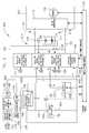
- FIG. 1schematically illustrates a propulsion system according to an embodiment of the invention.
- FIG. 2schematically illustrates another embodiment of the propulsion system.
- FIG. 3schematically illustrates another embodiment of the propulsion system.
- a systemis shown to include an electric drive, a first energy storage system comprising at least a high specific-power energy storage device, such as an ultracapacitor, and a second energy storage system electrically coupled to the electric drive through a direct current (DC) link.
- Both the first energy storage system and the second energy storage systemare electrically coupled to a multi-channel bi-directional boost converter.
- the positive terminal of the high specific-power energy storage deviceis also coupled to the negative terminal of the second energy storage system to bypass the multi-channel bi-directional boost converter.
- Propulsion system 100includes, in part, a first energy storage system comprising an energy battery 102 and a high specific-power energy storage device 104 .
- Propulsion system 100also includes a multi-channel bi-directional boost converter 106 .
- High specific-power energy storage device 104may be, for example, an ultracapacitor.
- an ultracapacitorrepresents a capacitor comprising multiple capacitor cells coupled to one another, where the capacitor cells may each have a capacitance that is greater than 500 Farads.
- the term energy battery used hereindescribes a high specific energy battery or high energy density battery demonstrated to achieve an energy density on the order of 100 W-hr/kg or greater (e.g., a Li-ion, sodium-metal halide, sodium nickel chloride, sodium-sulfur, or zinc-air battery).
- Energy battery 102 and high specific-power energy storage device 104are coupled together on a low-voltage side 202 of multi-channel bi-directional boost converter 106 , wherein a negative terminal 204 of energy battery 102 and a negative terminal 206 of high specific-power energy storage device 104 are coupled to a bus 108 , while a positive terminal 208 of energy battery 102 is coupled to a bus 110 , which is a positive bus that connects through an inductor to one channel of multi-channel bi-directional boost converter 106 on the low-voltage side 202 of multi-channel bi-directional boost converter 106 .
- a positive terminal 210 of high specific-power energy storage device 104is coupled to a bus 220 , which is coupled through an inductor on the low-voltage side 202 at a second channel (b) of multi-channel bi-directional boost converter 106 .
- System 100further includes a second energy storage system, which comprises an energy storage device 112 , and an AC traction drive 212 , which includes a DC-AC inverter 114 and an AC motor 116 coupled to a high-voltage side 214 of multi-channel bi-directional boost converter 106 .
- Energy storage device 112may be, for example, a battery having a high specific-power rating. Alternatively, energy storage device 112 may also be an ultracapacitor.
- AC traction drive 212in an alternative embodiment, may be replaced by a DC traction drive (not shown) by replacing inverter 114 with a DC chopper (not shown) and by replacing AC motor 116 with a DC motor (not shown).
- Energy storage device 112is coupled with multi-channel bi-directional boost converter 106 via a positive DC link 118 .
- DC-AC inverter 114is also coupled to positive DC link 118 and a negative DC link 120 , through which DC-AC inverter 114 receives a DC voltage and then supplies an alternating current to AC motor 116 .
- Negative DC link 120typically has the same potential as bus 108 on low-voltage side 202 of multi-channel bi-directional boost converter 106 .
- multi-channel bi-directional boost converter 106acts to boost the voltage provided by low-voltage side 202 of system 100 to high-voltage side 214 of system 100 , as well as to regulate the voltage and provide over-current protection to energy battery 102 , high specific-power energy storage device 104 , and energy storage device 112 .
- energy storage device 112(or the combination of energy storage device 112 and high specific-power energy storage device 104 ) is generally capable of providing sufficient voltage to power the AC motor 116 such that a vehicle may be operated at a relatively slow speed, the voltage provided to the AC motor 116 during periods of increased acceleration may need to be supplemented.
- energy from energy battery 102 on low-voltage side 202 of multi-channel bi-directional boost converter 106is utilized to provide the voltage necessary for increased acceleration of the vehicle.
- Energy from energy battery 102is used when the State of Charge (SOC) of high specific-power energy storage device 104 is depleted below some predetermined minimum value, typically a value below the voltage of battery 102 .
- SOCState of Charge
- a unidirectional coupling device 122conducts such that the multi-channel bi-directional boost converter 106 extracts energy primarily from energy battery 102 using two channels of the multi-channel bi-directional boost converter 106 , thereby allowing approximately twice the rated power compared to a single channel of the multi-channel bi-directional boost converter 106 .
- Unidirectional coupling device 122is shown to be a diode in the embodiment of FIG. 1 , but it is to be understood that unidirectional conducting apparatus 122 could be implemented using other known components and circuit techniques. Such a configuration acts to facilitate increasing the operation speed of the vehicle, particularly when the available energy of high specific-power energy storage device 104 is depleted or near a predetermined voltage limit.
- energy battery 102 voltagecan be boosted to the high side DC links 118 and 120 via low side (channel “a”) of multi-channel bi-directional boost converter 106 through positive bus 110 .
- the voltage provided by energy battery 102 through positive bus 110 and/or high specific-power energy storage device 104 through a positive bus 220is “boosted,” or increased, via the multi-channel bi-directional boost converter 106 by a boost ratio typically greater than 2:1.
- the voltage and power needed to accelerate AC motor 116may be provided due to the voltage-boosting capabilities of multi-channel bi-directional boost converter 106 .
- energy from the energy battery 102may be utilized to charge one or both of high specific-power energy storage device 104 and energy storage device 112 simultaneously via multi-channel bi-directional boost converter 106 .
- multi-channel bi-directional boost converter 106While the operation of multi-channel bi-directional boost converter 106 may be sufficient under normal operating conditions (e.g., low acceleration and/or deceleration), the efficiency of multi-channel bi-directional boost converters such as multi-channel bi-directional boost converter 106 may degrade during high acceleration or deceleration of the vehicle. That is, as there is an increase in the ratio of voltage required to sufficiently power an AC motor versus voltage available on the respective low voltage sides of the multi-channel bi-directional boost converter, a multi-channel bi-directional boost converter may experience increased electrical loss, leading to thermal cycling stresses due to an increase in electrical current through components of the multi-channel bi-directional boost converter.
- FIG. 1addresses this issue to greatly improve the efficiency of system 100 , especially during operation at relatively high power, high speed vehicle acceleration and deceleration.
- the positive terminal 210 of high specific-power energy storage device 104is coupled in series with the negative terminal 216 of energy storage system 112 via a link 124 .
- Link 124bypasses one channel of multi-channel bi-directional boost converter 106 to enable the voltage outputs of high specific-power energy storage device 104 and energy storage device 112 to be summed, thereby utilizing the high specific-power characteristics of high specific-power energy storage device 104 and energy storage device 112 .
- the combined voltage of these two energy storage devicescan be used to provide sufficient voltage and power to AC motor 116 without incurring losses related to passing current through multi-channel bi-directional boost converter 106 .
- coupling high specific-power energy storage device 104 and second energy storage device 112 in seriesenables fewer battery cells to be used as compared to conventional traction battery systems having one or more traction batteries directly coupled to a DC link of an inverter or load, thereby reducing cost, weight, balancing, and reliability issues.
- high specific-power energy storage device 104 and energy storage device 112also provides for greater efficiency for energy capture during regenerative braking events. Unlike energy battery 102 , both high specific-power energy storage device 104 and energy storage device 112 are operable at a low SOC and are capable of rapid high power electrical charge acceptance. As such, these energy storage devices are capable of accepting much of the regenerative power from the high voltage regenerated energy generated by AC motor 116 during overhauling loads such as vehicle deceleration.
- regenerative energycan be efficiently stored in high specific-power energy storage device 104 and energy storage device 112 , again without incurring the losses associated with the limitations of multi-channel bi-directional boost converter 106 , as link 124 enables the bypass of multi-channel bi-directional boost converter 106 .
- the energy stored in high specific-power energy storage device 104 and energy storage device 112can then be used for subsequent accelerations, which again improves the overall efficiency of the entire propulsion system 100 .
- Multi-channel bi-directional boost converter 106is operable as an Energy Management System (EMS) to adaptively control these energy levels based on parameters such as vehicle speed, AC traction drive torque demand, AC traction drive speed, and various electrical characteristics of the energy storage units, such as SOC, voltage levels, state of health, and temperature.
- EMSEnergy Management System
- multi-channel bi-directional boost converter 106to independently control the amount of energy supplied by high specific-power energy storage device 104 and/or energy battery 102 during typical vehicle acceleration.
- multi-channel bi-directional boost converter 106operates to control the amount of regenerated energy provided to energy storage device 112 , high specific-power energy storage device 104 , and/or energy battery 102 to maximize the overall charge acceptance of the system. Such dynamic control greatly improves the overall efficiency of system 100 .
- FIG. 2illustrates another embodiment of the invention.
- Propulsion system 200 shown in FIG. 2includes components similar to components shown in system 100 of FIG. 1 , and thus numbers used to indicate components in FIG. 1 will also be used to indicate similar components in FIG. 2 .
- system 200includes the components of system 100 , along with additional components such as a plurality of voltage sensors 126 , a current sensor 128 , a pre-charge circuit 132 , and a Vehicle System Control (VSC) 134 .
- Pre-charge circuit 132acts to provide an initial pre-charge to a DC link filter capacitor 218 associated with DC-AC Inverter 114 , plus other filter and energy storage capacitors associated with the EMS during vehicle start-up.
- VCS 134which receives operator inputs such as start-up, acceleration, and deceleration, and controls the operation of system 200 accordingly.
- energy battery 102 , high specific-power energy storage device 104 , multi-channel bi-directional boost converter 106 , and energy storage device 112 of system 200may be operated similarly to that described above with respect to system 100 .
- energy battery 102may be removed from the first energy storage system, thereby making high specific-power energy storage device 104 the only energy storage device on low-voltage side 202 of system 200 .
- Such a configurationwould primarily be used in hybrid-electric drive-train configurations, wherein a heat engine (not shown) could supplement the energy provided via the first energy storage system and the second energy storage system.
- FIG. 3illustrates yet another embodiment of the invention.
- Propulsion system 300 shown in FIG. 3includes components similar to components shown in systems 100 and 200 of FIGS. 1 and 2 , and thus numbers used to indicate components in FIGS. 1 and 2 will also be used to indicate similar components in FIG. 3 .
- system 300includes an auxiliary power unit 302 on low-voltage side 202 of multi-channel bi-directional boost converter 106 .
- Auxiliary power unit 302comprises a heat engine 136 , an alternator 138 , and a rectifier 140 .
- Auxiliary power unit 302 of system 300also includes a plug-in electrical system comprising an AC plug 142 , an isolation transformer 144 , a Ground Fault Current Interrupter (GFI) 146 , and a rectifier 148 .
- the output of rectifier 140is coupled to bus 222 such that energy produced by heat engine 136 and alternator 138 may supplement the energy provided by high specific-power energy storage device 104 , and/or energy battery 102 .
- energy battery 102 , high specific-power energy storage device 104 , and energy storage device 112selectively may be recharged using energy provided via heat engine 136 , alternator 138 , and rectifier 140 . Control of the current, voltage, and power is controlled during recharge operation via VSC 134 and the EMS.
- AC plug 142may be coupled to an external electrical power source (i.e., the utility grid) to supply energy through rectifier 148 to the energy storage devices 102 , 104 , 112 in system 300 .
- the output 304 of rectifier 148is coupled through an inductor to a separate channel (e.g., channel “c”) of multi-channel bi-directional boost converter 106 such that voltage, current, and power from the external electrical power source is controlled and is capable of being provided to any of energy battery 102 , high specific-power energy storage device 104 , and energy storage device 112 in system 300 .
- channel “c”separate channel
- a contactor 130acts to prevent enablement of DC-AC inverter 114 during charging of energy battery 102 , high specific-power energy storage device 104 , and energy storage device 112 when the system is plugged into an electric utility interface via AC plug 142 . While contactor 130 is shown between energy storage device 112 and DC-AC inverter 114 , contactor 130 may be located elsewhere in system 300 , including each phase on AC motor 116 . Accordingly, when incorporated into a vehicle, system 300 shown in FIG. 3 is not only capable of energy recharge via heat engine 136 while under operation, but can also be recharged when the vehicle is not in use.
- system 300 illustrated in FIG. 3is shown without a unidirectional coupling device (e.g., a diode) between energy battery 102 and high specific-power energy storage device 104 .
- a unidirectional coupling devicee.g., a diode
- high specific-power energy storage device 104may be discharged to a value substantially lower than the voltage of energy battery 102 . In this way, the efficiency of system 300 during operation of AC motor 116 at low speed and low power is greatly improved.
Landscapes
- Engineering & Computer Science (AREA)
- Power Engineering (AREA)
- Transportation (AREA)
- Mechanical Engineering (AREA)
- Life Sciences & Earth Sciences (AREA)
- Sustainable Development (AREA)
- Sustainable Energy (AREA)
- Electric Propulsion And Braking For Vehicles (AREA)
- Charge And Discharge Circuits For Batteries Or The Like (AREA)
- Direct Current Feeding And Distribution (AREA)
Abstract
Description
Claims (24)
Priority Applications (5)
| Application Number | Priority Date | Filing Date | Title |
|---|---|---|---|
| US13/224,669US8922057B2 (en) | 2009-08-11 | 2011-09-02 | System for multiple energy storage and management and method of making same |
| US13/283,829US9000614B2 (en) | 2009-08-11 | 2011-10-28 | System for multiple energy storage and management and method of making same |
| US13/283,983US8916993B2 (en) | 2009-08-11 | 2011-10-28 | System for multiple energy storage and management and method of making same |
| US13/283,931US8829719B2 (en) | 2009-08-11 | 2011-10-28 | System for multiple energy storage and management and method of making same |
| US14/562,042US9809128B2 (en) | 2009-08-11 | 2014-12-05 | System for multiple energy storage and management and method of making same |
Applications Claiming Priority (2)
| Application Number | Priority Date | Filing Date | Title |
|---|---|---|---|
| US12/539,056US8026638B2 (en) | 2009-08-11 | 2009-08-11 | System for multiple energy storage and management and method of making same |
| US13/224,669US8922057B2 (en) | 2009-08-11 | 2011-09-02 | System for multiple energy storage and management and method of making same |
Related Parent Applications (2)
| Application Number | Title | Priority Date | Filing Date |
|---|---|---|---|
| US12/536,056ContinuationUS8163028B2 (en) | 2007-01-10 | 2009-08-05 | Knee joint prosthesis system and method for implantation |
| US12/539,056ContinuationUS8026638B2 (en) | 2009-08-11 | 2009-08-11 | System for multiple energy storage and management and method of making same |
Related Child Applications (3)
| Application Number | Title | Priority Date | Filing Date |
|---|---|---|---|
| US13/283,829Continuation-In-PartUS9000614B2 (en) | 2009-08-11 | 2011-10-28 | System for multiple energy storage and management and method of making same |
| US13/283,983Continuation-In-PartUS8916993B2 (en) | 2009-08-11 | 2011-10-28 | System for multiple energy storage and management and method of making same |
| US13/283,931Continuation-In-PartUS8829719B2 (en) | 2009-08-11 | 2011-10-28 | System for multiple energy storage and management and method of making same |
Publications (2)
| Publication Number | Publication Date |
|---|---|
| US20110316345A1 US20110316345A1 (en) | 2011-12-29 |
| US8922057B2true US8922057B2 (en) | 2014-12-30 |
Family
ID=43301945
Family Applications (2)
| Application Number | Title | Priority Date | Filing Date |
|---|---|---|---|
| US12/539,056Active2030-03-25US8026638B2 (en) | 2009-08-11 | 2009-08-11 | System for multiple energy storage and management and method of making same |
| US13/224,669Active2031-06-13US8922057B2 (en) | 2009-08-11 | 2011-09-02 | System for multiple energy storage and management and method of making same |
Family Applications Before (1)
| Application Number | Title | Priority Date | Filing Date |
|---|---|---|---|
| US12/539,056Active2030-03-25US8026638B2 (en) | 2009-08-11 | 2009-08-11 | System for multiple energy storage and management and method of making same |
Country Status (4)
| Country | Link |
|---|---|
| US (2) | US8026638B2 (en) |
| EP (1) | EP2284037B1 (en) |
| JP (1) | JP5674379B2 (en) |
| CN (1) | CN101992678B (en) |
Cited By (2)
| Publication number | Priority date | Publication date | Assignee | Title |
|---|---|---|---|---|
| US9895983B2 (en) | 2013-10-11 | 2018-02-20 | General Electric Company | Propulsion system and method for driving a vehicle |
| US10272788B2 (en) | 2015-08-28 | 2019-04-30 | General Electric Company | Hybrid system with multiple energy storage devices |
Families Citing this family (31)
| Publication number | Priority date | Publication date | Assignee | Title |
|---|---|---|---|---|
| US8916993B2 (en) | 2009-08-11 | 2014-12-23 | General Electric Company | System for multiple energy storage and management and method of making same |
| IT1396298B1 (en)* | 2009-10-06 | 2012-11-16 | Bottero Spa | MACHINE FOR WORKING / HANDLING GLASS SHEETS. |
| US8299738B2 (en)* | 2009-11-20 | 2012-10-30 | Hamilton Sundstrand Corporation | Multi-tasking power processor for a vehicle electric system |
| US20120056600A1 (en)* | 2010-09-03 | 2012-03-08 | Nevin Donald M | Capacitor vehicle having high speed charging ability and method of operating a capacitor vehicle |
| TWI433427B (en)* | 2010-11-25 | 2014-04-01 | Ind Tech Res Inst | Battery power system |
| KR101243909B1 (en)* | 2010-12-16 | 2013-03-14 | 삼성에스디아이 주식회사 | System for energy storage and control method thereof |
| US8761978B2 (en)* | 2011-03-23 | 2014-06-24 | General Electric Company | System for supplying propulsion energy from an auxiliary drive and method of making same |
| CN102244391A (en)* | 2011-07-12 | 2011-11-16 | 华北电力大学 | Energy storage grid-connected circuit based on lithium batteries and super capacitor and control method thereof |
| US8963365B2 (en)* | 2011-08-12 | 2015-02-24 | General Electric Company | System and method for optimizing energy storage device cycle life |
| DE102011110639A1 (en)* | 2011-08-18 | 2013-02-21 | Deutsches Zentrum für Luft- und Raumfahrt e.V. | Power supply control device for supplying electrical power to rail vehicle, has control unit controlling supply of energy from different sources of energy in response to characteristics of sources and by request for operation of vehicle |
| US9073438B2 (en) | 2011-10-28 | 2015-07-07 | General Electric Company | System for selectively coupling an energy source to a load and method of making same |
| US8981727B2 (en) | 2012-05-21 | 2015-03-17 | General Electric Company | Method and apparatus for charging multiple energy storage devices |
| US9174525B2 (en) | 2013-02-25 | 2015-11-03 | Fairfield Manufacturing Company, Inc. | Hybrid electric vehicle |
| CN103144526A (en)* | 2013-03-01 | 2013-06-12 | 中国第一汽车股份有限公司 | Hybrid power vehicle using composite power supply power system |
| DE102013206296A1 (en)* | 2013-04-10 | 2014-10-16 | Robert Bosch Gmbh | Method for operating a power supply unit for a motor vehicle electrical system |
| WO2015060139A1 (en)* | 2013-10-25 | 2015-04-30 | 新神戸電機株式会社 | Power storage system |
| CN104660045B (en)* | 2013-11-25 | 2018-06-12 | 南京博兰得电子科技有限公司 | Electrical energy changer with energy storage management |
| US9834098B2 (en) | 2014-01-30 | 2017-12-05 | General Electric Company | Vehicle propulsion system with multi-channel DC bus and method of manufacturing same |
| US9108633B1 (en)* | 2014-03-13 | 2015-08-18 | GM Global Technology Operations LLC | Hybrid powertrain and method of controlling same |
| US20160082844A1 (en)* | 2014-09-23 | 2016-03-24 | General Electric Company | Methods and systems for multiple source energy storage, management, and control |
| DE102015203003A1 (en)* | 2015-02-19 | 2016-08-25 | Robert Bosch Gmbh | Battery storage system with different cell types |
| CA2999803A1 (en) | 2015-09-25 | 2017-03-30 | Hemant Karamchand Rohera | A power generating system and method for a vehicle |
| JP6240649B2 (en)* | 2015-11-28 | 2017-11-29 | 本田技研工業株式会社 | Power supply system |
| US9931944B2 (en)* | 2016-03-22 | 2018-04-03 | Ford Global Technologies, Llc | Variable voltage convert system with reduced bypass diode conduction |
| CN107521354B (en) | 2016-06-22 | 2020-06-16 | 华为技术有限公司 | Driving system and driving method of electric automobile |
| IT201600112523A1 (en)* | 2016-11-08 | 2018-05-08 | Magneti Marelli Spa | "Energy management apparatus supplied to a low voltage system of a motor vehicle comprising an energy recovery stage and relative process" |
| JP2019122201A (en)* | 2018-01-10 | 2019-07-22 | 本田技研工業株式会社 | Electric vehicle |
| CN108705935A (en)* | 2018-05-23 | 2018-10-26 | 精进电动科技股份有限公司 | Control the device and electric vehicle of the generated output of the range extender system of electric vehicle |
| CN110994993B (en)* | 2019-12-30 | 2021-01-29 | 施耐德电气(中国)有限公司 | Multichannel bidirectional buck-boost circuit |
| KR20230019741A (en)* | 2021-08-02 | 2023-02-09 | 주식회사 엘지에너지솔루션 | Apparatus for controlling battery, method of the same and system for controling battery |
| EP4383496A1 (en)* | 2022-12-08 | 2024-06-12 | Hitachi Energy Ltd | An energy storage system for a direct current transmission system and a method for exchanging energy with a direct current transmission |
Citations (8)
| Publication number | Priority date | Publication date | Assignee | Title |
|---|---|---|---|---|
| US5373195A (en) | 1992-12-23 | 1994-12-13 | General Electric Company | Technique for decoupling the energy storage system voltage from the DC link voltage in AC electric drive systems |
| US5710699A (en) | 1996-05-28 | 1998-01-20 | General Electric Company | Power electronic interface circuits for batteries and ultracapacitors in electric vehicles and battery storage systems |
| US20040100149A1 (en) | 2002-11-22 | 2004-05-27 | Jih-Sheng Lai | Topologies for multiple energy sources |
| US7049792B2 (en) | 1998-11-12 | 2006-05-23 | General Electric Company | Method and apparatus for a hybrid battery configuration for use in an electric or hybrid electric motive power system |
| US20060125319A1 (en) | 2004-12-15 | 2006-06-15 | King Robert D | System and method for providing power control of an energy storage system |
| US20070158118A1 (en) | 2006-01-09 | 2007-07-12 | General Electric Company | Vehicle propulsion system |
| US20070164693A1 (en) | 2006-01-18 | 2007-07-19 | Robert Dean King | Vehicle propulsion system |
| US20080113268A1 (en) | 2006-10-23 | 2008-05-15 | Buiel Edward R | Recombinant Hybrid Energy Storage Device |
Family Cites Families (6)
| Publication number | Priority date | Publication date | Assignee | Title |
|---|---|---|---|---|
| JP3612572B2 (en)* | 1996-09-10 | 2005-01-19 | 中国電力株式会社 | Motor drive power supply |
| JP3950262B2 (en)* | 1999-06-08 | 2007-07-25 | 中国電力株式会社 | Motor drive power converter |
| US6323608B1 (en)* | 2000-08-31 | 2001-11-27 | Honda Giken Kogyo Kabushiki Kaisha | Dual voltage battery for a motor vehicle |
| JP2004116296A (en)* | 2002-09-24 | 2004-04-15 | Honda Motor Co Ltd | Power supply for vehicles |
| CN100444495C (en)* | 2003-01-24 | 2008-12-17 | 三菱电机株式会社 | Power circuit for battery |
| JP2007236064A (en)* | 2006-02-28 | 2007-09-13 | Daikin Ind Ltd | Energy storage device |
- 2009
- 2009-08-11USUS12/539,056patent/US8026638B2/enactiveActive
- 2010
- 2010-07-27EPEP10170852.7Apatent/EP2284037B1/enactiveActive
- 2010-08-09JPJP2010178267Apatent/JP5674379B2/enactiveActive
- 2010-08-11CNCN201010260530.1Apatent/CN101992678B/enactiveActive
- 2011
- 2011-09-02USUS13/224,669patent/US8922057B2/enactiveActive
Patent Citations (8)
| Publication number | Priority date | Publication date | Assignee | Title |
|---|---|---|---|---|
| US5373195A (en) | 1992-12-23 | 1994-12-13 | General Electric Company | Technique for decoupling the energy storage system voltage from the DC link voltage in AC electric drive systems |
| US5710699A (en) | 1996-05-28 | 1998-01-20 | General Electric Company | Power electronic interface circuits for batteries and ultracapacitors in electric vehicles and battery storage systems |
| US7049792B2 (en) | 1998-11-12 | 2006-05-23 | General Electric Company | Method and apparatus for a hybrid battery configuration for use in an electric or hybrid electric motive power system |
| US20040100149A1 (en) | 2002-11-22 | 2004-05-27 | Jih-Sheng Lai | Topologies for multiple energy sources |
| US20060125319A1 (en) | 2004-12-15 | 2006-06-15 | King Robert D | System and method for providing power control of an energy storage system |
| US20070158118A1 (en) | 2006-01-09 | 2007-07-12 | General Electric Company | Vehicle propulsion system |
| US20070164693A1 (en) | 2006-01-18 | 2007-07-19 | Robert Dean King | Vehicle propulsion system |
| US20080113268A1 (en) | 2006-10-23 | 2008-05-15 | Buiel Edward R | Recombinant Hybrid Energy Storage Device |
Cited By (2)
| Publication number | Priority date | Publication date | Assignee | Title |
|---|---|---|---|---|
| US9895983B2 (en) | 2013-10-11 | 2018-02-20 | General Electric Company | Propulsion system and method for driving a vehicle |
| US10272788B2 (en) | 2015-08-28 | 2019-04-30 | General Electric Company | Hybrid system with multiple energy storage devices |
Also Published As
| Publication number | Publication date |
|---|---|
| CN101992678B (en) | 2014-07-30 |
| US20110316345A1 (en) | 2011-12-29 |
| CN101992678A (en) | 2011-03-30 |
| US8026638B2 (en) | 2011-09-27 |
| EP2284037A3 (en) | 2017-03-01 |
| US20110037320A1 (en) | 2011-02-17 |
| EP2284037A2 (en) | 2011-02-16 |
| JP2011041461A (en) | 2011-02-24 |
| EP2284037B1 (en) | 2023-10-11 |
| JP5674379B2 (en) | 2015-02-25 |
Similar Documents
| Publication | Publication Date | Title |
|---|---|---|
| US8922057B2 (en) | System for multiple energy storage and management and method of making same | |
| US9809128B2 (en) | System for multiple energy storage and management and method of making same | |
| US9000614B2 (en) | System for multiple energy storage and management and method of making same | |
| US8120290B2 (en) | Energy management system to improve efficiency of electric and hybrid drive trains | |
| US8829719B2 (en) | System for multiple energy storage and management and method of making same | |
| JP7051758B2 (en) | Devices and methods for charging electric vehicles | |
| US10195929B2 (en) | Electrically-driven vehicle | |
| EP1976721B1 (en) | Vehicle propulsion system | |
| KR101202572B1 (en) | System and method for providing power control of an energy storage system | |
| CA2574470C (en) | Vehicle propulsion system | |
| US9013168B2 (en) | System for transferring energy from an energy source and method of making same | |
| CA2916815C (en) | Bi-directional dc-dc power converter for a vehicle system | |
| JP6527785B2 (en) | Drive device and transportation equipment | |
| JP2009508763A (en) | Plug-in hybrid propulsion power electronics equipment with high-speed energy storage device and control method and apparatus | |
| JP2016106511A (en) | Electric vehicle | |
| CN205292311U (en) | Six rounds of individual drive hybrid vehicle | |
| JP2018182856A (en) | Composite power storage system |
Legal Events
| Date | Code | Title | Description |
|---|---|---|---|
| AS | Assignment | Owner name:GENERAL ELECTRIC COMPANY, NEW YORK Free format text:ASSIGNMENT OF ASSIGNORS INTEREST;ASSIGNORS:KING, ROBERT DEAN;KILINSKI, GARY RAYMOND;REEL/FRAME:026851/0130 Effective date:20090811 | |
| STCF | Information on status: patent grant | Free format text:PATENTED CASE | |
| MAFP | Maintenance fee payment | Free format text:PAYMENT OF MAINTENANCE FEE, 4TH YEAR, LARGE ENTITY (ORIGINAL EVENT CODE: M1551) Year of fee payment:4 | |
| MAFP | Maintenance fee payment | Free format text:PAYMENT OF MAINTENANCE FEE, 8TH YEAR, LARGE ENTITY (ORIGINAL EVENT CODE: M1552); ENTITY STATUS OF PATENT OWNER: LARGE ENTITY Year of fee payment:8 | |
| AS | Assignment | Owner name:EDISON INNOVATIONS, LLC, TEXAS Free format text:ASSIGNMENT OF ASSIGNORS INTEREST;ASSIGNOR:DOLBY INTELLECTUAL PROPERTY LICENSING, LLC;REEL/FRAME:070293/0273 Effective date:20250219 | |
| AS | Assignment | Owner name:GE INTELLECTUAL PROPERTY LICENSING, LLC, NEW YORK Free format text:ASSIGNMENT OF ASSIGNORS INTEREST;ASSIGNOR:GENERAL ELECTRIC COMPANY;REEL/FRAME:070636/0815 Effective date:20240630 Owner name:DOLBY INTELLECTUAL PROPERTY LICENSING, LLC, NEW YORK Free format text:CHANGE OF NAME;ASSIGNOR:GE INTELLECTUAL PROPERTY LICENSING, LLC;REEL/FRAME:070643/0907 Effective date:20240819 |