US8921098B2 - Instrument for monitoring DNA replication - Google Patents
Instrument for monitoring DNA replicationDownload PDFInfo
- Publication number
- US8921098B2 US8921098B2US11/406,148US40614806AUS8921098B2US 8921098 B2US8921098 B2US 8921098B2US 40614806 AUS40614806 AUS 40614806AUS 8921098 B2US8921098 B2US 8921098B2
- Authority
- US
- United States
- Prior art keywords
- instrument
- reaction regions
- reaction
- lens
- emission
- Prior art date
- Legal status (The legal status is an assumption and is not a legal conclusion. Google has not performed a legal analysis and makes no representation as to the accuracy of the status listed.)
- Expired - Fee Related, expires
Links
Images


Classifications
- G—PHYSICS
- G01—MEASURING; TESTING
- G01N—INVESTIGATING OR ANALYSING MATERIALS BY DETERMINING THEIR CHEMICAL OR PHYSICAL PROPERTIES
- G01N21/00—Investigating or analysing materials by the use of optical means, i.e. using sub-millimetre waves, infrared, visible or ultraviolet light
- G01N21/62—Systems in which the material investigated is excited whereby it emits light or causes a change in wavelength of the incident light
- G01N21/63—Systems in which the material investigated is excited whereby it emits light or causes a change in wavelength of the incident light optically excited
- G01N21/64—Fluorescence; Phosphorescence
- G01N21/6428—Measuring fluorescence of fluorescent products of reactions or of fluorochrome labelled reactive substances, e.g. measuring quenching effects, using measuring "optrodes"
- B—PERFORMING OPERATIONS; TRANSPORTING
- B01—PHYSICAL OR CHEMICAL PROCESSES OR APPARATUS IN GENERAL
- B01L—CHEMICAL OR PHYSICAL LABORATORY APPARATUS FOR GENERAL USE
- B01L7/00—Heating or cooling apparatus; Heat insulating devices
- B01L7/52—Heating or cooling apparatus; Heat insulating devices with provision for submitting samples to a predetermined sequence of different temperatures, e.g. for treating nucleic acid samples
- C—CHEMISTRY; METALLURGY
- C12—BIOCHEMISTRY; BEER; SPIRITS; WINE; VINEGAR; MICROBIOLOGY; ENZYMOLOGY; MUTATION OR GENETIC ENGINEERING
- C12Q—MEASURING OR TESTING PROCESSES INVOLVING ENZYMES, NUCLEIC ACIDS OR MICROORGANISMS; COMPOSITIONS OR TEST PAPERS THEREFOR; PROCESSES OF PREPARING SUCH COMPOSITIONS; CONDITION-RESPONSIVE CONTROL IN MICROBIOLOGICAL OR ENZYMOLOGICAL PROCESSES
- C12Q1/00—Measuring or testing processes involving enzymes, nucleic acids or microorganisms; Compositions therefor; Processes of preparing such compositions
- C12Q1/68—Measuring or testing processes involving enzymes, nucleic acids or microorganisms; Compositions therefor; Processes of preparing such compositions involving nucleic acids
- C12Q1/6844—Nucleic acid amplification reactions
- C12Q1/686—Polymerase chain reaction [PCR]
- G—PHYSICS
- G01—MEASURING; TESTING
- G01N—INVESTIGATING OR ANALYSING MATERIALS BY DETERMINING THEIR CHEMICAL OR PHYSICAL PROPERTIES
- G01N21/00—Investigating or analysing materials by the use of optical means, i.e. using sub-millimetre waves, infrared, visible or ultraviolet light
- G01N21/17—Systems in which incident light is modified in accordance with the properties of the material investigated
- G01N21/25—Colour; Spectral properties, i.e. comparison of effect of material on the light at two or more different wavelengths or wavelength bands
- G01N21/27—Colour; Spectral properties, i.e. comparison of effect of material on the light at two or more different wavelengths or wavelength bands using photo-electric detection ; circuits for computing concentration
- G01N21/274—Calibration, base line adjustment, drift correction
- G—PHYSICS
- G01—MEASURING; TESTING
- G01N—INVESTIGATING OR ANALYSING MATERIALS BY DETERMINING THEIR CHEMICAL OR PHYSICAL PROPERTIES
- G01N21/00—Investigating or analysing materials by the use of optical means, i.e. using sub-millimetre waves, infrared, visible or ultraviolet light
- G01N21/62—Systems in which the material investigated is excited whereby it emits light or causes a change in wavelength of the incident light
- G01N21/63—Systems in which the material investigated is excited whereby it emits light or causes a change in wavelength of the incident light optically excited
- G01N21/64—Fluorescence; Phosphorescence
- G01N21/645—Specially adapted constructive features of fluorimeters
- G01N21/6452—Individual samples arranged in a regular 2D-array, e.g. multiwell plates
- B—PERFORMING OPERATIONS; TRANSPORTING
- B01—PHYSICAL OR CHEMICAL PROCESSES OR APPARATUS IN GENERAL
- B01L—CHEMICAL OR PHYSICAL LABORATORY APPARATUS FOR GENERAL USE
- B01L2200/00—Solutions for specific problems relating to chemical or physical laboratory apparatus
- B01L2200/10—Integrating sample preparation and analysis in single entity, e.g. lab-on-a-chip concept
- B—PERFORMING OPERATIONS; TRANSPORTING
- B01—PHYSICAL OR CHEMICAL PROCESSES OR APPARATUS IN GENERAL
- B01L—CHEMICAL OR PHYSICAL LABORATORY APPARATUS FOR GENERAL USE
- B01L2300/00—Additional constructional details
- B01L2300/06—Auxiliary integrated devices, integrated components
- B01L2300/0627—Sensor or part of a sensor is integrated
- B01L2300/0654—Lenses; Optical fibres
- B—PERFORMING OPERATIONS; TRANSPORTING
- B01—PHYSICAL OR CHEMICAL PROCESSES OR APPARATUS IN GENERAL
- B01L—CHEMICAL OR PHYSICAL LABORATORY APPARATUS FOR GENERAL USE
- B01L2300/00—Additional constructional details
- B01L2300/06—Auxiliary integrated devices, integrated components
- B01L2300/0627—Sensor or part of a sensor is integrated
- B01L2300/0663—Whole sensors
- B—PERFORMING OPERATIONS; TRANSPORTING
- B01—PHYSICAL OR CHEMICAL PROCESSES OR APPARATUS IN GENERAL
- B01L—CHEMICAL OR PHYSICAL LABORATORY APPARATUS FOR GENERAL USE
- B01L2300/00—Additional constructional details
- B01L2300/18—Means for temperature control
- B01L2300/1805—Conductive heating, heat from thermostatted solids is conducted to receptacles, e.g. heating plates, blocks
- B01L2300/1811—Conductive heating, heat from thermostatted solids is conducted to receptacles, e.g. heating plates, blocks using electromagnetic induction heating
- B—PERFORMING OPERATIONS; TRANSPORTING
- B01—PHYSICAL OR CHEMICAL PROCESSES OR APPARATUS IN GENERAL
- B01L—CHEMICAL OR PHYSICAL LABORATORY APPARATUS FOR GENERAL USE
- B01L3/00—Containers or dishes for laboratory use, e.g. laboratory glassware; Droppers
- B01L3/50—Containers for the purpose of retaining a material to be analysed, e.g. test tubes
- B01L3/508—Containers for the purpose of retaining a material to be analysed, e.g. test tubes rigid containers not provided for above
- B01L3/5085—Containers for the purpose of retaining a material to be analysed, e.g. test tubes rigid containers not provided for above for multiple samples, e.g. microtitration plates
- C—CHEMISTRY; METALLURGY
- C12—BIOCHEMISTRY; BEER; SPIRITS; WINE; VINEGAR; MICROBIOLOGY; ENZYMOLOGY; MUTATION OR GENETIC ENGINEERING
- C12Q—MEASURING OR TESTING PROCESSES INVOLVING ENZYMES, NUCLEIC ACIDS OR MICROORGANISMS; COMPOSITIONS OR TEST PAPERS THEREFOR; PROCESSES OF PREPARING SUCH COMPOSITIONS; CONDITION-RESPONSIVE CONTROL IN MICROBIOLOGICAL OR ENZYMOLOGICAL PROCESSES
- C12Q2545/00—Reactions characterised by their quantitative nature
- C12Q2545/10—Reactions characterised by their quantitative nature the purpose being quantitative analysis
- C12Q2545/101—Reactions characterised by their quantitative nature the purpose being quantitative analysis with an internal standard/control
- G—PHYSICS
- G01—MEASURING; TESTING
- G01N—INVESTIGATING OR ANALYSING MATERIALS BY DETERMINING THEIR CHEMICAL OR PHYSICAL PROPERTIES
- G01N21/00—Investigating or analysing materials by the use of optical means, i.e. using sub-millimetre waves, infrared, visible or ultraviolet light
- G01N21/62—Systems in which the material investigated is excited whereby it emits light or causes a change in wavelength of the incident light
- G01N21/63—Systems in which the material investigated is excited whereby it emits light or causes a change in wavelength of the incident light optically excited
- G01N21/64—Fluorescence; Phosphorescence
- G01N2021/6417—Spectrofluorimetric devices
- G01N2021/6419—Excitation at two or more wavelengths
- G—PHYSICS
- G01—MEASURING; TESTING
- G01N—INVESTIGATING OR ANALYSING MATERIALS BY DETERMINING THEIR CHEMICAL OR PHYSICAL PROPERTIES
- G01N21/00—Investigating or analysing materials by the use of optical means, i.e. using sub-millimetre waves, infrared, visible or ultraviolet light
- G01N21/62—Systems in which the material investigated is excited whereby it emits light or causes a change in wavelength of the incident light
- G01N21/63—Systems in which the material investigated is excited whereby it emits light or causes a change in wavelength of the incident light optically excited
- G01N21/64—Fluorescence; Phosphorescence
- G01N2021/6417—Spectrofluorimetric devices
- G01N2021/6421—Measuring at two or more wavelengths
- G—PHYSICS
- G01—MEASURING; TESTING
- G01N—INVESTIGATING OR ANALYSING MATERIALS BY DETERMINING THEIR CHEMICAL OR PHYSICAL PROPERTIES
- G01N21/00—Investigating or analysing materials by the use of optical means, i.e. using sub-millimetre waves, infrared, visible or ultraviolet light
- G01N21/62—Systems in which the material investigated is excited whereby it emits light or causes a change in wavelength of the incident light
- G01N21/63—Systems in which the material investigated is excited whereby it emits light or causes a change in wavelength of the incident light optically excited
- G01N21/64—Fluorescence; Phosphorescence
- G01N21/6428—Measuring fluorescence of fluorescent products of reactions or of fluorochrome labelled reactive substances, e.g. measuring quenching effects, using measuring "optrodes"
- G01N2021/6439—Measuring fluorescence of fluorescent products of reactions or of fluorochrome labelled reactive substances, e.g. measuring quenching effects, using measuring "optrodes" with indicators, stains, dyes, tags, labels, marks
- G01N2021/6441—Measuring fluorescence of fluorescent products of reactions or of fluorochrome labelled reactive substances, e.g. measuring quenching effects, using measuring "optrodes" with indicators, stains, dyes, tags, labels, marks with two or more labels
- G—PHYSICS
- G01—MEASURING; TESTING
- G01N—INVESTIGATING OR ANALYSING MATERIALS BY DETERMINING THEIR CHEMICAL OR PHYSICAL PROPERTIES
- G01N21/00—Investigating or analysing materials by the use of optical means, i.e. using sub-millimetre waves, infrared, visible or ultraviolet light
- G01N21/62—Systems in which the material investigated is excited whereby it emits light or causes a change in wavelength of the incident light
- G01N21/63—Systems in which the material investigated is excited whereby it emits light or causes a change in wavelength of the incident light optically excited
- G01N21/64—Fluorescence; Phosphorescence
- G01N21/645—Specially adapted constructive features of fluorimeters
- G01N2021/6463—Optics
- G—PHYSICS
- G01—MEASURING; TESTING
- G01N—INVESTIGATING OR ANALYSING MATERIALS BY DETERMINING THEIR CHEMICAL OR PHYSICAL PROPERTIES
- G01N21/00—Investigating or analysing materials by the use of optical means, i.e. using sub-millimetre waves, infrared, visible or ultraviolet light
- G01N21/62—Systems in which the material investigated is excited whereby it emits light or causes a change in wavelength of the incident light
- G01N21/63—Systems in which the material investigated is excited whereby it emits light or causes a change in wavelength of the incident light optically excited
- G01N21/64—Fluorescence; Phosphorescence
- G01N21/645—Specially adapted constructive features of fluorimeters
- G01N2021/6482—Sample cells, cuvettes
- G—PHYSICS
- G01—MEASURING; TESTING
- G01N—INVESTIGATING OR ANALYSING MATERIALS BY DETERMINING THEIR CHEMICAL OR PHYSICAL PROPERTIES
- G01N2201/00—Features of devices classified in G01N21/00
- G01N2201/02—Mechanical
- G01N2201/024—Modular construction
- G01N2201/0245—Modular construction with insertable-removable part
- G—PHYSICS
- G01—MEASURING; TESTING
- G01N—INVESTIGATING OR ANALYSING MATERIALS BY DETERMINING THEIR CHEMICAL OR PHYSICAL PROPERTIES
- G01N2201/00—Features of devices classified in G01N21/00
- G01N2201/06—Illumination; Optics
- G01N2201/061—Sources
- G01N2201/06113—Coherent sources; lasers
- G—PHYSICS
- G01—MEASURING; TESTING
- G01N—INVESTIGATING OR ANALYSING MATERIALS BY DETERMINING THEIR CHEMICAL OR PHYSICAL PROPERTIES
- G01N2201/00—Features of devices classified in G01N21/00
- G01N2201/06—Illumination; Optics
- G01N2201/062—LED's
- G01N2201/0628—Organic LED [OLED]
- G—PHYSICS
- G01—MEASURING; TESTING
- G01N—INVESTIGATING OR ANALYSING MATERIALS BY DETERMINING THEIR CHEMICAL OR PHYSICAL PROPERTIES
- G01N2201/00—Features of devices classified in G01N21/00
- G01N2201/06—Illumination; Optics
- G01N2201/063—Illuminating optical parts
- G01N2201/0635—Structured illumination, e.g. with grating
- G—PHYSICS
- G01—MEASURING; TESTING
- G01N—INVESTIGATING OR ANALYSING MATERIALS BY DETERMINING THEIR CHEMICAL OR PHYSICAL PROPERTIES
- G01N2201/00—Features of devices classified in G01N21/00
- G01N2201/06—Illumination; Optics
- G01N2201/063—Illuminating optical parts
- G01N2201/0636—Reflectors
- G—PHYSICS
- G01—MEASURING; TESTING
- G01N—INVESTIGATING OR ANALYSING MATERIALS BY DETERMINING THEIR CHEMICAL OR PHYSICAL PROPERTIES
- G01N2201/00—Features of devices classified in G01N21/00
- G01N2201/06—Illumination; Optics
- G01N2201/068—Optics, miscellaneous
Definitions
- This inventionrelates to biochemical analyses, and particularly to quantitative monitoring of DNA during a polymerase chain reaction (PCR) process.
- PCRpolymerase chain reaction
- PCRPolymerase chain reaction
- a thermal cycler blockhas one or more wells for holding vials containing a suspension of ingredients for a reaction to produce more DNA starting with “seed” samples of the DNA.
- the starting ingredients in an aqueous suspensioninclude selected DNA primer strands, DNA elements, enzymes and other chemicals.
- the temperature of the blockis cycled between a lower temperature extension phase of the PCR reaction at about 60° C., which is the phase where all of the DNA strands have recombined into double strands, and a high temperature denaturing phase at about 95° C., during which the DNA is denatured or split into single strands.
- a temperature programessentially doubles the DNA in each cycle, thus providing a method for replicating significant amounts of the DNA from a small starting quantity.
- the PCR processis taught, for example, in U.S. Pat. No. 4,683,202.
- Prior measuring techniqueshave utilized microvolume fluorometers (spectrofluorometers) and a simple arrangement of a video camera with illumination lamps. Such apparatus utilize dyes that fluoresce in the presence of double-stranded DNA. These techniques and instruments are not particularly adapted to PCR apparatus for routine monitoring of the reaction. There also is a need for greater precision during the monitoring and measurements. Previous instruments that allow real time acquisition and analysis of PCR data have been very basic devices without the required dynamic range, do not have built-in calibration means, do not allow operation with sample well caps, or are very expensive.
- An object of the present inventionis to provide a novel optical instrument for quantitative monitoring of DNA replication in a PCR apparatus.
- Other objectsare to provide such an instrument with improved dynamic range, automatic selection of exposure time to extend dynamic range, automatic adjustment for drift, simplified operation, relatively low cost, and easy changing of optics to accommodate different fluorescent dyes.
- an optical instrumentas described herein for monitoring polymerase chain reaction replication of DNA.
- the replicationis in a reaction apparatus that includes a thermal cycler block for holding at least one vial containing a suspension of ingredients for the reaction.
- the ingredientsinclude a fluorescent dye that fluoresces proportionately in presence of DNA.
- the instrumentincludes a light source, means for directing light beams, a light detector, and means for processing data signals.
- the light sourceemits a source beam having at least a primary excitation frequency that causes the dye to fluoresce at an emission frequency.
- a first meansis disposed to be receptive of the source beam to effect an excitation beam having the excitation frequency.
- a primary focusing meansis disposed to focus the excitation beam into each suspension such that the primary dye emits an emission beam having the emission frequency and an intensity representative of concentration of DNA in each suspension. The focusing means is receptive of and passes the emission beam.
- a second meansis disposed to be receptive of the emission beam from the focusing means so as to further pass the emission beam at the emission frequency to another focusing means that focuses the emission beam onto a detector.
- the detectorgenerates primary data signals representative of the emission beam and thereby a corresponding concentration of DNA in each vial.
- a processoris receptive of the primary data signals for computing and displaying the concentration of DNA.
- the first means and the second meanstogether comprise a beam splitter that is receptive of the source beam to effect the excitation beam, and receptive of the emission beam to pass the emission beam to the detector.
- the blockis configured to hold a plurality of vials
- the focusing meanscomprises a corresponding plurality of vial lenses each disposed over a vial such that the emission beam comprises individual beams each associated with a vial.
- the focusing meansmay further comprise a field lens such as a Fresnel lens disposed cooperatively with the vial lenses to effect focusing of the excitation beam into each suspension, and to pass the individual beams to the second means (beam splitter).
- the detectorpreferably comprises an array of photoreceptors receptive of the individual beams to generate corresponding data signals such that the processing means computes concentration of DNA in each vial.
- the instrumentshould also include an excitation filter between the light source and the beam splitter, and an emission filter between the beam splitter and the detector.
- the splitter and filtersare associated with a selected primary dye in the suspension.
- a filter modulecontains the splitter and filters, and the module is removable from the housing for replacement with another module associated with another selected primary dye.
- a fluorescent reference memberemits reference light in response to the excitation beam.
- the referenceis disposed to be receptive of a portion of the excitation beam from the first means.
- a portion of the reference lightis passed by the second means as a reference beam to the detector, so as to generate reference signals for utilization in the computing of the concentration of DNA.
- the reference membercomprises a plurality of reference emitters, each emitting a reference beam of different intensity in response to the excitation beam, to allow selection by the processor of a reference set having the highest data signals that are less than a predetermined maximum that is less than the saturation limit.
- the detectoris operatively connected to the processing means for the detector to integrate emission beam input over a preselected exposure time for generating each set of data signals, and the processing means or the detector or a combination thereof have a saturation limit for the data signals.
- the processing meanscomprises adjustment means for automatically effecting adjustments in exposure time to maintain the primary data within a predetermined operating range for maintaining corresponding data signals less than the saturation limit, and means for correcting the primary data in proportion to the adjustments in exposure time.
- the processorcomputes photoreceptor data from the data signals for each photoreceptor, and the adjustment means ascertains highest photoreceptor data, determines whether the highest photoreceptor data are less than, within or higher than the predetermined operating range and, based on such determination, the exposure time is increased, retained or reduced so as to effect a subsequent exposure time for maintaining subsequent photoreceptor data within the predetermined operating range.
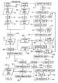
- FIG. 1is a schematic of an optical train for an optical instrument according to the invention, associated with a polymerase chain reaction (PCR) reaction apparatus.
- PCRpolymerase chain reaction
- FIG. 2is a perspective of the instrument of FIG. 1 with a side panel removed.
- FIG. 3is an exploded perspective of a module shown in FIG. 2 .
- FIG. 4is a perspective of a reference member in the optical train of FIG. 1 .
- FIG. 5is a flow chart for computing DNA concentration from data obtained with the instrument of FIG. 1 .
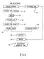
- FIG. 6is a flow chart for determining exposure time for data acquisition in operation of the instrument of FIG. 1 and for computations in the flow chart of FIG. 5 .
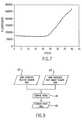
- FIG. 7is a graph of extension phase data of fluorescence vs. cycles from operation of the instrument of FIG. 1 with a PCR apparatus.
- FIG. 8is a flow chart for computing secondary data for computations in the flow chart of FIG. 5 .
- FIG. 9is a flow chart for computing ratios between the plurality of reference emitter segments of the reference member of FIG. 4
- An optical instrument A of the inventionis utilized with or incorporated into a reaction apparatus B that replicates (“amplifies”) selected portions of DNA by polymerase chain reaction (“PCR”).
- the reaction apparatusis conventional and should function without interference from the instrument which monitors the amount of DNA in real time during replication. Suitable reaction apparatus are described in U.S. Pat. Nos. 5,475,610 and 5,656,493.
- the reaction apparatus( FIG. 1 ) is conventional and has two main components, namely a thermal cycler block 1 with wells 1 a for holding at least one vial 1 b containing a suspension of ingredients for the reaction, and a thermal cycle controller 1 c for cycling the temperature of the block through a specified temperature program.
- the starting ingredients of the aqueous suspension of sample materialsinclude a “seed” sample of DNA, selected DNA primer strands, DNA elements, enzymes and other chemicals.
- the blocktypically aluminum, is heated and cooled in a prescribed cycle by electrical means, liquid or air coolant, or a combination of these, or other means to achieve the cycling.
- the suspensions in the vialsare thereby cycled between two temperature phases so as to effect the polymerase chain reaction.
- phaseis a lower temperature extension phase of the PCR reaction at about 60° C., which is the phase where all of the DNA strands have recombined into double strands, and a high temperature denaturing phase at about 95° C., during which the DNA is denatured or split into single strands.
- the samplealso contains a fluorescent dye that fluoresces proportionately and more strongly in the presence of double stranded DNA to which the dye binds, for example SYBR Green dye (available from Molecular Probes, Inc., Eugene, Oreg.) that fluoresces in the presence of double stranded DNA.
- SYBR Green dyeavailable from Molecular Probes, Inc., Eugene, Oreg.
- Another type of fluorescent dye labeled “probes”, which are DNA-like structures with complimentary sequences to selected DNA strand portions,may also be used. Other dyes that have similar characteristics may be utilized.
- the term “marker dye”refers to the type that binds to double stranded DNA, or to the probe type, or to any other type of dye that attaches to DNA so as to fluoresce in proportion to the quantity of DNA.
- Samplesmay also contain an additional, passive dye (independent of the DNA) to serve as a reference as described below. Under incidence of light having a correct excitation frequency, generally a dye fluoresces to emit light at an emission frequency that is lower than that of the excitation light.
- the vialstypically are formed conically in a plastic unitary tray containing a plurality of vials, for example 96 in an array of 12 by 8.
- the traypreferably is removable from the block for preparations.
- a plastic unitary cover with caps 1 d for the vialsmay rest or attach over the vials to prevent contamination and evaporation loss. Other means may be used for this function, such as oil on the sample surface, in which case caps are not needed. If used, the caps are transparent to light utilized in the instrument, and may be convex facing upwardly.
- the monitoring instrumentis mounted over the block containing the vials.
- the instrumentis removable or swings away for access to the vials.
- a platen 2rests over the vial caps or, if none, directly over the vials.
- the platenadvantageously aluminum, has an array of holes 2 a therethrough aligned with the vials, each hole having a diameter about the same as the vial top diameter. If there are caps, the platen should have its temperature maintained by a film heater or other means for heating the platen sufficiently to prevent condensation under the caps without interfering with DNA replication in the vials, for example holding the platen at slightly higher temperature than the highest sample temperature that the thermal cycler reaches.
- each of the vialsis a lens 2 b positioned for its focal point to be approximately centered in the suspension in the vial.
- a field lens 3to provide a telecentric optical system.
- the field lensis an aspherically corrected Fresnel lens for minimal distortion.
- a neutral density pattern (not shown) to correct nonuniformities in illumination and imagingmay be mounted on or in proximity to the field lens, for example to attenuate light in the center of the image field.
- a folding optical mirroris optionally mounted at 45° for convenient packaging. This may be omitted, or other such folding optics may be used.
- the field lens, and/or the vial lenseseach may be comprised of two or more lenses that effect the required focusing, the word “lens” herein including such multiplicities.
- a light source 11 for a source beam 20 of lightis provided, for example a 100 watt halogen lamp. Preferably this is mounted at a focal distance of an ellipsoid reflector 11 a which produces a relatively uniform pattern over the desired area.
- the reflectorshould be dichroic, i.e. substantially reflecting visible light and transmitting infrared light, to restrict infrared from the other optical components and from overheating the instrument. This is further aided by a heat reflecting mirror 13 in the optical path.
- a mechanical or electronic shutter 12allows blockage of the light source for obtaining dark data.
- the type of light sourceis not critical, and other types may be used such as a projection lamp or a laser, with appropriate optical elements.
- a beam splitter 6is disposed to receive the source beam 20 .
- thisis a dichroic reflector such that, positioned at 45°, it reflects light having an excitation frequency that causes the marker dye to fluoresce at an emission frequency, and passes light having the emission frequency.
- Such a conventional optical devicetypically utilizes optical interference layers to provide the specific frequency response.
- the beam splitteris positioned to reflect the source beam to the folding mirror.
- the source beamis reflected from the splitter as a excitation beam 22 having substantially the excitation-frequency.
- the excitation beamis focused by the field lens 3 and then as separated beams 24 by the vial (well) lenses 2 b into the center of the vials.
- the marker dyeis thereby caused to emit light at the emission frequency. This light is passed upwardly as an emission beam in the form of individual beams 26 that are reflected from the folding mirror 5 to the beam splitter 6 which passes the emission beam through to a detector 10 .
- the vial lenses 2 b and the field lens 3constitute a primary focusing means for focusing both the excitation beam and the emission beam.
- the field lensmay be omitted so that the focusing means consists only of the vial lenses 2 b .
- the vial lensesmay be omitted so that the focusing means consists only of an objective lens in the field lens position to focus the individual emission beams on the detector.
- the beam splitter 6may pass the source beam as an excitation beam and reflect the emission beam, with appropriate rearrangement of the lamp and the detector.
- other angles than 45°could be used if more suitable for the beam splitter, such as a more perpendicular reflection and pass through.
- the beam splittersplits the optical paths for the excitation beam and the emission beam, and other variations that achieve this may be suitable. It is desirable to minimize source light reaching the detector, which the dichroic device helps achieve A non-dichroic beam splitter may be used but would be less efficient as significant source light may reach the detector, or may be reflected or transmitted in the wrong direction and lost.
- an excitation filter 7is disposed between the light source 11 and the beam splitter 6 . This passes light having the excitation frequency and substantially blocks light having the emission frequency.
- an emission filter 8is disposed between the beam splitter and the detector, in this case between the splitter and a detector lens 9 in front of the detector. This filter passes light having the emission frequency and substantially blocks light having the excitation frequency.
- a detector lensis preferred, a focusing reflector may be substituted for the detector lens.
- Such an emission focusing meansmay be located after (as shown) or before the beam splitter and on either side of the emission filter, and alternatively may be integrated into the primary focusing means.
- the field lensmay be an objective lens that focuses the emission beam onto the detector.
- Suitable filtersare conventional optical bandpass filters utilizing optical interference films, each having a bandpass at a frequency optimum either for excitation of the fluorescent dye or its emission.
- Each filtershould have very high attenuation for the other (non-bandpass) frequency, in order to prevent “ghost” images from reflected and stray light.
- the excitation filter bandpassshould center around 485 nm wavelength
- the emission filter bandpassshould center around 555 nm.
- the beam splittershould transition from reflection to transmission between these two, e.g. about 510 nm, so that light less than this wavelength is reflected and higher wavelength light is passed through.
- the excitation filter and the beam splitter togetherconstitute a first means disposed to be receptive of the source beam to effect an excitation beam having the excitation frequency
- the emission filter and the beam splitter togetherconstitute a second means disposed to be receptive of the emission beam from the focusing means so as to pass the emission beam at the emission frequency to the detector.
- the beam splitteralternatively may pass the source beam as an excitation beam and reflect the emission beam to the detector.
- the filtersmay be omitted, and the first means is represented by the beam splitter effecting the exitation beam from the source beam, and the second means is represented by the beam splitter passing the emission beam to the detector.
- the beam splittermay be omitted, and the first means may constitute an excitation filter for the excitation frequency, the second means may constitute an emission filter for the emission frequency, with the light source and the detector being side by side so that the excitation and emission beams are on slightly different optical paths angularly.
- the source and detectorneed not actually be side by side with one or more folding mirrors.
- use of the beam splitteris preferred so that the excitation and emission beams through the field lens will have the same optical path.
- the beam splitter 6 , the excitation filter 7 and the emission filter 8are affixed in a module 30 ( FIG. 2 ) that is associated with a selected primary dye for the suspension.
- the moduleis removable from the housing 32 of the instrument A for replacement with another module containing different beam splitter and filters associated with another selected primary dye.
- the instrumentincludes a lamp subhousing 33 and a camera subhousing 35 .
- each moduleincludes a mounting block 34 with a flange 36 that is affixable to the housing with a single screw 38 .
- the beam splitter 6is held at 45° in the block with a frame 40 and screws 42 .
- the emission filter 8mounts (e.g. with glue) into the block.
- the excitation filter 7mounts similarly into a mounting member 44 that is held by screws 46 to the block. With the module in place, the instrument is closed up with a side plate 47 that is screwed on. Positioning pins (not shown) ensure repeatable alignment.
- the replacement modulemay have the same mounting block and associated components, with the beam splitter and filters replaced.
- the detector lens 9( FIG. 1 ) is cooperative with the vial lenses 2 b and the field lens 3 to focus the individual beams on the detector 10 .
- the lensshould be large aperture, low distortion and minimum vignetting.
- the detectorpreferably is an array detector, for example a charge injection device (CID) or, preferably, a charge coupled device (CCD).
- CIDcharge injection device
- CCDcharge coupled device
- a conventional video camera containing a CCD detector, the detector lens and associated electronics for the detectorshould be suitable, such as an Electrim model 1000L which has 751 active pixels horizontal and 242 (non-interlaced) active pixels vertical.
- This cameraincludes a circuit board that directly interfaces to a computer ISA bus. No framegrabber circuitry is required with this camera.
- any other digital imaging device or subsystemmay be used or adapted that is capable of taking still or freeze-frame images for post processing in a computer.
- a detector with a multiplicity of photoreceptors (pixels) 78is preferable if there are a plurality of vials, to provide separate monitoring of each.
- a scanning devicemay be used with a single photodetector, for example by scanning the folding mirror and using a small aperture to the detector.
- a simple devicesuch as a photomultipier may be used if there is only one vial.
- a CCDreceives light for a selected integration period and, after analog/digital conversion, reads out digital signal data at a level accumulated in this period. The integration is effectively controlled by an electronic shutter, and a frame transfer circuit is desirable. Signal data are generated for each pixel, including those receiving the individual beams of emitted light from the vials.
- the instrumentpreferably includes a fluorescent reference member 4 that emits reference light in response to the excitation beam.
- the reference memberis formed of a plurality of reference emitters, e.g. 6, each emitting a reference beam of different intensity in response to the excitation beam.
- the range of these intensitiesshould approximate the range of intensities expected from the marker dye in the vials, for example each segment may be separated in brightness by about a factor of 2.5.
- the reference memberis disposed to receive a portion of the excitation beam from the beam splitter. A good location is adjacent to the field lens, so that the optical paths associated with the member approximate those of the vials.
- Most of the reference lightpasses back through the beam splitter as a reference beam to the detector.
- the detector pixelsreceive the emission beam to generate reference signals for utilization along with the data signals in the computing of the concentration of DNA.
- the reference member 4( FIG. 4 ) comprises a plastic fluorescent strip 4 a and a neutral density filter 4 b mounted over the fluorescent-strip, optionally with an air space 4 h between, such that a portion of the excitation beam and the reference beam are attenuated by the neutral density filter.
- the neutral density filterhas a series of densities 4 c to effect the plurality of reference emitters (segments) each emitting a reference beam of different intensity.
- a heating strip 4 d and an aluminum strip 4 g to smooth the heatingare mounted in a trough 4 e on the bottom thereof, and the fluorescent strip is mounted on the aluminum strip over the heating strip.
- this assemblypreferably is covered by a transparent plexiglass window (not shown, so as to display the varying density filter).
- the heating stripis controlled to maintain the fluorescent strip at a constant temperature against the thermal cycles of the cycler block and other effects. This is done because most fluorescent materials change in fluorescence inversely with temperature.
- the computer processor 14may be a conventional PC.
- the computer programmingis conventional such as with “C”. Adaptations of the programming for the present invention will be readily recognized and achieved by those skilled in the art.
- the processorselectively processes signals from pixels receiving light from the vials and the reference emitters, ignoring surrounding light.
- the programmingtherefore advantageously includes masking to define the pixel regions of interest (ROI), e.g. as disclosed in copending provisional patent application Ser. No. 60/092,785 filed Jul. 14, 1998 of the present assignee. Mechanical alignment of the optics may be necessary to cooperatively focus the beams into the programmed regions of interest.
- ROIpixel regions of interest
- the analog data signalsare fed to the processor through an analog/digital (A/D) device 15 which, for the present purpose, is considered to be part of the processor
- a saturation levelis proscribed by either the detector or the A/D or, preferably, the CCD dynamic range is matched to the A/D dynamic range.
- a suitable rangeis 8 bits of precision (256 levels), and the CCD amplifier offset is set so that the dark signal output of the CCD (with the shutter 12 closed) is within the A/D range.
- the processorinstructs the detector with selected exposure time to maintain the output within the dynamic range.
- fluorescence dataare taken from the plurality of vials (e.g. 96 regions of interest) and from the reference emitter segments, for each cycle in a DNA reaction replication sequence of thermal cycles, typically 40 to 50.
- Two data setsare taken ( FIG. 5 ) for each thermal cycle during the extension phase of the PCR reaction at about 60° C., which is the phase where all of the DNA strands have recombined into double strands.
- One setis normal primary data 50 (along with reference data described below) and the other is dark signal data 51 with the mechanical shutter closed. Both digital data sets 50 , 51 are converted by the A/D 15 from respective analog data signals 48 , 49 from the detector.
- the darkare subtracted 55 from the normal, to yield dark-corrected data 57 .
- the subtractionis pixel by pixel.
- total dark for each region of interestare subtracted from corresponding total fluorescence data.
- Dataare taken simultaneously from the reference strip which has, for example, 6 segments together with the 96 vials for a total of 102 regions of interest.
- the processing meansprovides for automatic adjustment of the exposure time to maintain the data signals within a predetermined operating range that is less than the saturation limit during the DNA replication sequence, for example 35% to 70% of saturation.
- Computations for DNA concentrationinclude corrections in proportion to adjustments in exposure lime ( FIG. 6 ).
- Signal data 50 , 51 from each exposure 52 , 53are obtained during a previously determined exposure time 54 by totaling the pixel counts within each region of interest (ROI).
- the highest signal data 56which is data from one or more highest pixel readings, such as the three highest-reading contiguous pixels, is searched out 58 from the corresponding data signals 50 . From a comparison 62 it is determined whether the highest signal data are less than, within or higher than the selected operating range 60 . Based on such determination, the exposure time is adjusted 64 , i.e. increased, retained or reduced, to obtain the subsequent exposure time 66 .
- a reference time 68( FIG. 5 ) also is selected which may be, for example, an initial time or a fixed standard time such as 1024 ms.
- the dark-corrected data 57is time-corrected 69 to yield corrected primary data 71 , dividing by ratio of actual exposure time to the reference time. The first several cycles may be out of range, and thereafter a useful fluorescence curve should be obtained ( FIG. 7 ).
- reference data signals 73are generated and converted by the A/D 15 to reference data 72 .
- Selected reference data 74 from a specific reference segment 4 care selected 76 as that data having the highest signal strength that is less than a predetermined maximum 77 that, in turn, is less than the saturation limit, e.g. 70%.
- a next dimmer segmentis also selected 75 , and the selected reference data 74 include the data from that segment.
- the dark data 51are subtracted 78 from the reference data 74 , and the dark-corrected data 80 are adjusted 84 for exposure time 54 to yield adjusted reference data 82 .
- the data 82includes dark corrected data 82 ′ for the highest segment and dark corrected data 82 ′′ for the next dimmer segment ( FIG. 9 ).
- the ratios of brightness between each segmentare computed 89 and built up over the course of data collection. Each time data is collected, the ratio between the highest and next dimmer segment is calculated. As different optimum segments are selected on succeeding data collections, a table of ratios 85 is assembled. Alternatively, these rations may be collected and calculated in advance.
- This adjusted reference data 82 ′(from data 82 , FIG. 5 ) are utilized for computing normalized reference data 88 which are normalized 86 in real time as a ratio to reference data 90 from an initial or other selected previous cycle in the DNA replication (PCR) sequence by working back with the ratios 85 .
- the normalized reference dataare utilized on the corrected primary data 71 in a normalization computation 92 to provide drift normalized primary data 94 by dividing the primary data by the normalized reference data. This corrects for instrument drift during the monitoring.
- DNA concentration 96may then be computed 98 from a stored calibration factors 99 , determined by running standard known DNA concentrations to determine the slope and intercept of a line relating starting concentration to the starting cycle of the growth curve ( FIG. 7 ) as taught in the aforementioned article by Higuchi and U.S. Pat. No. 5,766,889. (Further normalization 118 , 120 and baseline correction 122 - 130 are discussed below.)
- Extension phase data for a typical PCR sequencewould look like FIG. 7 , plotted for each PCR cycle. If desired, the data may be corrected for dye bleaching or other sample chemical effects by normalizing to sample vials containing samples with the same dye and with DNA amplification prevented chemically.
- the sampleadditionally may contain one or more types of dye molecules that serve as a “passive” reference having some fluorescence in the same wavelength range as the DNA binding dye.
- This reference dyeis made up, for example, of a nucleic acid sequence labeled with Rhodamine and Fluorescein dye derivatives.
- a suitable referenceis Rox dye from Perkin-Elmer Applied Biosystems.
- These passive dye moleculesdo not take part in the PCR reaction, so that their fluorescence is substantially without influence from DNA and remains constant during the reaction. This fluorescence can be used to normalize the fluorescence from the DNA binding dye with a standard concentration of passive dye included in the ingredients of at least one vial, preferably in every vial.
- the source beamincludes a secondary excitation frequency that causes the passive dye to fluoresce at a secondary frequency and thereby emit a secondary beam directed to the detector to generate corresponding secondary data signals.
- the processoris receptive of the secondary data signals for computing secondary data representative of standard concentration. These data are used to normalize the primary data, so that the concentration of DNA is normalized to the standard concentration of passive dye after correcting computations of concentration of DNA in proportion to adjustments in exposure time, and in conjunction with the normalization for drift.
- the secondary excitation frequencyis identical to the primary excitation frequency, and the passive dye fluoresces such that the emitted secondary beam is substantially at the emission frequency.
- the primary data signalsare generated during each extension phase of cycling of the thermal cycler block when DNA is recombined and correspondingly primary dye emission is maximized.
- the secondary data signalsare generated during each denature phase of cycling of the thermal cycler block when DNA is denatured and correspondingly primary dye emission is minimized.
- data signals for the primary phaseare substantially representative of DNA concentration
- data signals for the secondary phaseare substantially representative of the standard concentration of passive dye.
- the dark and normal dataare taken for the vial samples and the reference strip, and the dark is subtracted from the normal fluorescence data.
- This dark and normal data setis taken during the extension phase of the PCR reaction at about 60° C., which is the phase where all of the DNA strands have recombined into double strands. During this phase, the fluorescence from the DNA binding dye is maximized, and the fluorescence from the passive reference molecules is superimposed but much smaller.
- a separate dark and normal data setis taken during the high temperature (about 95° C.) denaturing phase, during which the DNA is denatured or split into single strands.
- the denaturing phase imagessubstantially contain reference fluorescence from the passive reference molecules.
- the dark-corrected reference (denaturing) data setafter correction for measured temperature dependence, may be subtracted from the dark-corrected DNA binding dye data set or may be deemed insignificant for the normal data set.
- the passive reference dye labeled moleculesmay be desirable to image the passive reference dye labeled molecules by taking the additional images, for each PCR cycle, using a separate optical bandpass filter that rejects wavelengths emitted by the DNA binding dye while accepting wavelengths from the passive reference dye. This data would be functionally equivalent to the denature data.
- respective normal and dark data signals 102 , 104are obtained in the same manner as for the primary data, with normal exposure 52 ′ and closed shutter 53 ′.
- Exposure time 106may be the same as for an adjacent extension phase in the sequence, or determined from a previous denature phase run (as described with respect to FIG. 7 ), or may be a suitable time predetermined for all denature phases in the sequence.
- the A/D 15converts the signals to secondary data 108 and dark data 110 .
- the darkis subtracted 55 ′ from the secondary to yield dark-corrected data 112 which is further corrected 69 ′ with a reference time 114 and the actual exposure time 106 to yield corrected secondary data 116 .
- the extension cycle, drift normalized primary data 94then are normalized 118 by dividing by the average of a selected number (e.g. 10) of cycles for the denature phase corrected secondary data 116 to produce further normalized fluorescence data or further normalized data 120 , which removes sample well to well non-uniformity effects. Cycle by cycle division may be used in place of an average. Alternatively the secondary data may be applied to the corrected primary data 71 before or after drift normalization. Baseline samples may be selected 122 and averaged 124 to produce baseline data 126 . The further normalized data 120 are then divided 128 by the baseline data to yield baseline corrected data 130 . These baseline samples are selected so as to be before the PCR growth exceeds the nearly horizontal base line portion of the curve in FIG. 7 . Selected baseline cycles may be, for example, cycles 6 through 15 . After further normalization 118 , the further normalized data 118 are used to compute 98 DNA concentration 96 .
- a selected numbere.g. 10
- the datamay be used for various purposes, for example quantitative monitoring of the reaction or determination of replicated DNA concentration, or determination of the starting amount.
- the instrumentalso may be used (with or without normalizations and other corrections) simply to display whether replication is taking place during a sequence, or has taken place.
Landscapes
- Chemical & Material Sciences (AREA)
- Health & Medical Sciences (AREA)
- Physics & Mathematics (AREA)
- Life Sciences & Earth Sciences (AREA)
- Immunology (AREA)
- Biochemistry (AREA)
- General Health & Medical Sciences (AREA)
- Analytical Chemistry (AREA)
- General Physics & Mathematics (AREA)
- Pathology (AREA)
- Chemical Kinetics & Catalysis (AREA)
- Nuclear Medicine, Radiotherapy & Molecular Imaging (AREA)
- Engineering & Computer Science (AREA)
- Organic Chemistry (AREA)
- Molecular Biology (AREA)
- Proteomics, Peptides & Aminoacids (AREA)
- Zoology (AREA)
- Wood Science & Technology (AREA)
- Optics & Photonics (AREA)
- Clinical Laboratory Science (AREA)
- Spectroscopy & Molecular Physics (AREA)
- Biotechnology (AREA)
- Microbiology (AREA)
- Biophysics (AREA)
- Theoretical Computer Science (AREA)
- Mathematical Physics (AREA)
- Bioinformatics & Cheminformatics (AREA)
- General Engineering & Computer Science (AREA)
- Genetics & Genomics (AREA)
- Investigating, Analyzing Materials By Fluorescence Or Luminescence (AREA)
- Apparatus Associated With Microorganisms And Enzymes (AREA)
Abstract
Description
Claims (26)
Priority Applications (1)
| Application Number | Priority Date | Filing Date | Title |
|---|---|---|---|
| US11/406,148US8921098B2 (en) | 1998-05-16 | 2006-04-18 | Instrument for monitoring DNA replication |
Applications Claiming Priority (7)
| Application Number | Priority Date | Filing Date | Title |
|---|---|---|---|
| US8576598P | 1998-05-16 | 1998-05-16 | |
| US9278498P | 1998-07-14 | 1998-07-14 | |
| US09/700,536US6818437B1 (en) | 1998-05-16 | 1999-05-17 | Instrument for monitoring polymerase chain reaction of DNA |
| PCT/US1999/011088WO1999060381A1 (en) | 1998-05-16 | 1999-05-17 | Instrument for monitoring polymerase chain reaction of dna |
| US10/216,620US7008789B2 (en) | 1998-05-16 | 2002-08-09 | Instrument for monitoring polymerase chain reaction of DNA |
| US10/370,846US7183103B2 (en) | 1998-05-16 | 2003-02-20 | Instrument for monitoring polymerase chain reaction of DNA |
| US11/406,148US8921098B2 (en) | 1998-05-16 | 2006-04-18 | Instrument for monitoring DNA replication |
Related Parent Applications (1)
| Application Number | Title | Priority Date | Filing Date |
|---|---|---|---|
| US10/370,846ContinuationUS7183103B2 (en) | 1998-05-16 | 2003-02-20 | Instrument for monitoring polymerase chain reaction of DNA |
Publications (2)
| Publication Number | Publication Date |
|---|---|
| US20060199259A1 US20060199259A1 (en) | 2006-09-07 |
| US8921098B2true US8921098B2 (en) | 2014-12-30 |
Family
ID=27375133
Family Applications (10)
| Application Number | Title | Priority Date | Filing Date |
|---|---|---|---|
| US09/700,536Expired - LifetimeUS6818437B1 (en) | 1998-05-16 | 1999-05-17 | Instrument for monitoring polymerase chain reaction of DNA |
| US10/216,620Expired - LifetimeUS7008789B2 (en) | 1998-05-16 | 2002-08-09 | Instrument for monitoring polymerase chain reaction of DNA |
| US10/370,846Expired - Fee RelatedUS7183103B2 (en) | 1998-05-16 | 2003-02-20 | Instrument for monitoring polymerase chain reaction of DNA |
| US11/333,483Expired - Fee RelatedUS8557566B2 (en) | 1998-05-16 | 2006-01-17 | Instrument for monitoring polymerase chain reaction of DNA |
| US11/406,148Expired - Fee RelatedUS8921098B2 (en) | 1998-05-16 | 2006-04-18 | Instrument for monitoring DNA replication |
| US11/705,856AbandonedUS20070148761A1 (en) | 1998-05-16 | 2007-02-13 | Instrument for monitoring polymerase chain reaction of DNA |
| US11/711,416AbandonedUS20070154939A1 (en) | 1998-05-16 | 2007-02-26 | Instrument for monitoring polymerase chain reaction of DNA |
| US14/730,989Expired - Fee RelatedUS9273353B2 (en) | 1998-05-16 | 2015-06-04 | Instrument for monitoring polymerase chain reaction of DNA |
| US14/997,832AbandonedUS20160178521A1 (en) | 1998-05-16 | 2016-01-18 | Instrument for monitoring polymerase chain reaction of dna |
| US14/997,883AbandonedUS20160178522A1 (en) | 1998-05-16 | 2016-01-18 | Instrument for monitoring polymerase chain reaction of dna |
Family Applications Before (4)
| Application Number | Title | Priority Date | Filing Date |
|---|---|---|---|
| US09/700,536Expired - LifetimeUS6818437B1 (en) | 1998-05-16 | 1999-05-17 | Instrument for monitoring polymerase chain reaction of DNA |
| US10/216,620Expired - LifetimeUS7008789B2 (en) | 1998-05-16 | 2002-08-09 | Instrument for monitoring polymerase chain reaction of DNA |
| US10/370,846Expired - Fee RelatedUS7183103B2 (en) | 1998-05-16 | 2003-02-20 | Instrument for monitoring polymerase chain reaction of DNA |
| US11/333,483Expired - Fee RelatedUS8557566B2 (en) | 1998-05-16 | 2006-01-17 | Instrument for monitoring polymerase chain reaction of DNA |
Family Applications After (5)
| Application Number | Title | Priority Date | Filing Date |
|---|---|---|---|
| US11/705,856AbandonedUS20070148761A1 (en) | 1998-05-16 | 2007-02-13 | Instrument for monitoring polymerase chain reaction of DNA |
| US11/711,416AbandonedUS20070154939A1 (en) | 1998-05-16 | 2007-02-26 | Instrument for monitoring polymerase chain reaction of DNA |
| US14/730,989Expired - Fee RelatedUS9273353B2 (en) | 1998-05-16 | 2015-06-04 | Instrument for monitoring polymerase chain reaction of DNA |
| US14/997,832AbandonedUS20160178521A1 (en) | 1998-05-16 | 2016-01-18 | Instrument for monitoring polymerase chain reaction of dna |
| US14/997,883AbandonedUS20160178522A1 (en) | 1998-05-16 | 2016-01-18 | Instrument for monitoring polymerase chain reaction of dna |
Country Status (1)
| Country | Link |
|---|---|
| US (10) | US6818437B1 (en) |
Cited By (7)
| Publication number | Priority date | Publication date | Assignee | Title |
|---|---|---|---|---|
| US9671342B2 (en) | 1998-05-16 | 2017-06-06 | Life Technologies Corporation | Instrument for monitoring polymerase chain reaction of DNA |
| US9823195B2 (en) | 1998-05-16 | 2017-11-21 | Life Technologies Corporation | Optical instrument comprising multi-notch beam splitter |
| US10155978B2 (en) | 2016-11-08 | 2018-12-18 | Delta Electronics Int'l (Singapore) Pte Ltd | Multi-channel fluorescence detection device |
| US10450603B2 (en) | 2016-09-12 | 2019-10-22 | Delta Electronics Int'l (Singapore) Pte Ltd | Fluorescence detection device |
| US10753876B2 (en) | 2018-03-02 | 2020-08-25 | Delta Electronics Int'l (Singapore) Pte Ltd | Portable multi-color fluorescence detection device |
| US11815445B2 (en) | 2020-01-31 | 2023-11-14 | Delta Electronics, Inc. | Optical calibration tool |
| US20240003803A1 (en)* | 2018-09-17 | 2024-01-04 | Inguran, Llc | Light collection from objects within a fluid column |
Families Citing this family (111)
| Publication number | Priority date | Publication date | Assignee | Title |
|---|---|---|---|---|
| US7133726B1 (en)* | 1997-03-28 | 2006-11-07 | Applera Corporation | Thermal cycler for PCR |
| US6818437B1 (en)* | 1998-05-16 | 2004-11-16 | Applera Corporation | Instrument for monitoring polymerase chain reaction of DNA |
| US20050279949A1 (en)* | 1999-05-17 | 2005-12-22 | Applera Corporation | Temperature control for light-emitting diode stabilization |
| US7423750B2 (en)* | 2001-11-29 | 2008-09-09 | Applera Corporation | Configurations, systems, and methods for optical scanning with at least one first relative angular motion and at least one second angular motion or at least one linear motion |
| US6692700B2 (en) | 2001-02-14 | 2004-02-17 | Handylab, Inc. | Heat-reduction methods and systems related to microfluidic devices |
| US7829025B2 (en) | 2001-03-28 | 2010-11-09 | Venture Lending & Leasing Iv, Inc. | Systems and methods for thermal actuation of microfluidic devices |
| US7010391B2 (en) | 2001-03-28 | 2006-03-07 | Handylab, Inc. | Methods and systems for control of microfluidic devices |
| US8895311B1 (en) | 2001-03-28 | 2014-11-25 | Handylab, Inc. | Methods and systems for control of general purpose microfluidic devices |
| EP1384063A1 (en)* | 2001-05-03 | 2004-01-28 | Delta Dansk Elektronik, Lys & Akustik | Apparatus and sensing devices for measuring fluorescence lifetimes of fluorescence sensors |
| US6670617B2 (en)* | 2001-06-28 | 2003-12-30 | Ondeo Nalco Company | Mirror fluorometer |
| US7280207B2 (en)* | 2001-07-25 | 2007-10-09 | Applera Corporation | Time-delay integration in a flow cytometry system |
| US6982166B2 (en)* | 2002-05-16 | 2006-01-03 | Applera Corporation | Lens assembly for biological testing |
| US9157860B2 (en)* | 2002-05-16 | 2015-10-13 | Applied Biosystems, Llc | Achromatic lens array |
| GB2399776A (en)* | 2003-03-24 | 2004-09-29 | Pa Knowledge Ltd | Cyclical heating and cooling device and associated methods |
| US7148043B2 (en) | 2003-05-08 | 2006-12-12 | Bio-Rad Laboratories, Inc. | Systems and methods for fluorescence detection with a movable detection module |
| EP2407243B1 (en) | 2003-07-31 | 2020-04-22 | Handylab, Inc. | Multilayered microfluidic device |
| US7233393B2 (en) | 2004-08-05 | 2007-06-19 | Applera Corporation | Signal noise reduction for imaging in biological analysis |
| US7295316B2 (en)* | 2004-01-14 | 2007-11-13 | Applera Corporation | Fluorescent detector with automatic changing filters |
| JP2007518109A (en)* | 2004-01-14 | 2007-07-05 | アプレラ コーポレイション | Apparatus and method for fluorescence detection in biological samples |
| US8852862B2 (en) | 2004-05-03 | 2014-10-07 | Handylab, Inc. | Method for processing polynucleotide-containing samples |
| US20060030036A1 (en) | 2004-05-28 | 2006-02-09 | Victor Joseph | Chips for multiplex analyses |
| KR100604321B1 (en) | 2004-08-20 | 2006-07-25 | 삼성테크윈 주식회사 | Polymerase Chain Reaction Device |
| KR20060025402A (en) | 2004-09-16 | 2006-03-21 | 삼성전자주식회사 | Optical system for multichannel sample analysis and multichannel sample analyzer |
| US8084260B2 (en)* | 2004-11-24 | 2011-12-27 | Applied Biosystems, Llc | Spectral calibration method and system for multiple instruments |
| WO2006073893A2 (en)* | 2005-01-05 | 2006-07-13 | Atc Technologies, Llc | Adaptive beam forming with multi-user detection and interference reduction in satellite communiation systems and methods |
| DE602005000877T2 (en)* | 2005-01-18 | 2007-12-20 | Roche Diagnostics Gmbh | Fluorescence imaging by telecentricity |
| EP1681555B1 (en)* | 2005-01-18 | 2007-03-21 | Roche Diagnostics GmbH | Imaging of fluorescence signals using telecentric excitation and imaging optics |
| CA2967430C (en) | 2005-03-10 | 2018-05-08 | Gen-Probe Incorporated | Systems and methods to perform assays for detecting or quantifying analytes within samples |
| US7446288B2 (en)* | 2005-05-06 | 2008-11-04 | Applied Biosystems Inc. | Device including inductively heatable fluid retainment region, and method |
| WO2007005769A1 (en)* | 2005-06-30 | 2007-01-11 | Applera Corporation | Automated quality control method and system for genetic analysis |
| JP2007046904A (en)* | 2005-08-05 | 2007-02-22 | Sanyo Electric Co Ltd | Reaction detector |
| US7630849B2 (en) | 2005-09-01 | 2009-12-08 | Applied Biosystems, Llc | Method of automated calibration and diagnosis of laboratory instruments |
| US7727473B2 (en) | 2005-10-19 | 2010-06-01 | Progentech Limited | Cassette for sample preparation |
| US7754148B2 (en) | 2006-12-27 | 2010-07-13 | Progentech Limited | Instrument for cassette for sample preparation |
| US7998708B2 (en) | 2006-03-24 | 2011-08-16 | Handylab, Inc. | Microfluidic system for amplifying and detecting polynucleotides in parallel |
| WO2007112114A2 (en) | 2006-03-24 | 2007-10-04 | Handylab, Inc. | Integrated system for processing microfluidic samples, and method of using same |
| US11806718B2 (en) | 2006-03-24 | 2023-11-07 | Handylab, Inc. | Fluorescence detector for microfluidic diagnostic system |
| US10900066B2 (en) | 2006-03-24 | 2021-01-26 | Handylab, Inc. | Microfluidic system for amplifying and detecting polynucleotides in parallel |
| US8883490B2 (en) | 2006-03-24 | 2014-11-11 | Handylab, Inc. | Fluorescence detector for microfluidic diagnostic system |
| WO2007115059A2 (en) | 2006-03-29 | 2007-10-11 | Merial Limited | Vaccine against streptococci |
| US8232091B2 (en)* | 2006-05-17 | 2012-07-31 | California Institute Of Technology | Thermal cycling system |
| US7629124B2 (en)* | 2006-06-30 | 2009-12-08 | Canon U.S. Life Sciences, Inc. | Real-time PCR in micro-channels |
| DE102006036171B4 (en)* | 2006-07-28 | 2008-10-09 | Analytik Jena Ag | Arrangement and method for multichannel fluorescence measurement in PCR samples |
| WO2008024080A1 (en) | 2006-08-24 | 2008-02-28 | Agency For Science, Technology And Research | Compact optical detection system |
| WO2008061165A2 (en) | 2006-11-14 | 2008-05-22 | Handylab, Inc. | Microfluidic cartridge and method of making same |
| EP2099930B1 (en) | 2006-12-13 | 2015-02-18 | Luminex Corporation | Systems and methods for multiplex analysis of pcr in real time |
| JP2010516281A (en) | 2007-01-22 | 2010-05-20 | ウェハージェン,インコーポレイテッド | High-throughput chemical reaction equipment |
| US20080182263A1 (en)* | 2007-01-29 | 2008-07-31 | Applera Corporation | Systems and Methods for Calibration Using Dye Signal Amplification |
| WO2008136591A1 (en) | 2007-05-04 | 2008-11-13 | Sk Energy Co., Ltd. | A process for producing polycarbonates and a coordination complex used therefor |
| ES2599902T3 (en)* | 2007-06-15 | 2017-02-06 | Novartis Ag | Microscope system and method to obtain standardized sample data |
| WO2009002225A2 (en)* | 2007-06-25 | 2008-12-31 | Closed Company 'molecular-Medicine Technologies' | Multifunctional diagnosis device and a method for testing biological objects |
| RU2406764C2 (en)* | 2007-06-25 | 2010-12-20 | Закрытое акционерное общество "Молекулярно-медицинские технологии" | Device for diagnostics of liquid media in process of amplification and/or hybridisation |
| KR101089045B1 (en)* | 2007-06-28 | 2011-12-02 | (주)바이오니아 | Real-time monitoring device of nucleic acid amplification reaction product |
| EP3222733B1 (en) | 2007-07-13 | 2021-04-07 | Handylab, Inc. | Polynucleotide capture materials, and methods of using same |
| US8105783B2 (en) | 2007-07-13 | 2012-01-31 | Handylab, Inc. | Microfluidic cartridge |
| US8287820B2 (en) | 2007-07-13 | 2012-10-16 | Handylab, Inc. | Automated pipetting apparatus having a combined liquid pump and pipette head system |
| US8182763B2 (en) | 2007-07-13 | 2012-05-22 | Handylab, Inc. | Rack for sample tubes and reagent holders |
| US9618139B2 (en) | 2007-07-13 | 2017-04-11 | Handylab, Inc. | Integrated heater and magnetic separator |
| US9186677B2 (en) | 2007-07-13 | 2015-11-17 | Handylab, Inc. | Integrated apparatus for performing nucleic acid extraction and diagnostic testing on multiple biological samples |
| WO2009103003A2 (en)* | 2008-02-15 | 2009-08-20 | Bio-Rad Laboratories, Inc. | Scanning fluorescent reader with diffuser system |
| USD787087S1 (en) | 2008-07-14 | 2017-05-16 | Handylab, Inc. | Housing |
| GB0812926D0 (en)* | 2008-07-15 | 2008-08-20 | Assaymetrics Ltd | Spectrometer and method of operating a spectrometer |
| EP2148187A1 (en)* | 2008-07-25 | 2010-01-27 | Roche Diagnostics GmbH | Stimulation and optical display system for fluorescence detection |
| EP2350258B1 (en)* | 2008-10-24 | 2019-04-03 | The University of Notre Dame du Lac | Methods and apparatus to obtain suspended particle information |
| CN202830041U (en)* | 2009-04-03 | 2013-03-27 | Illumina公司 | Device for heating biological sample |
| CN201837588U (en) | 2009-09-09 | 2011-05-18 | 海利克斯公司 | Optical system for multiple reactions |
| KR102004319B1 (en) | 2010-02-23 | 2019-07-26 | 루미넥스 코포레이션 | Apparatus and methods for integrated sample preparation, reaction and detection |
| AU2012222178B2 (en) | 2011-02-24 | 2014-12-18 | Gen-Probe Incorporated | Systems and methods for distinguishing optical signals of different modulation frequencies in an optical signal detector |
| DE102011016138A1 (en)* | 2011-03-30 | 2012-10-04 | Karl Storz Gmbh & Co. Kg | Device for fluorescence diagnosis |
| EP2511693A1 (en) | 2011-04-13 | 2012-10-17 | F. Hoffmann-La Roche AG | Analysis System with a spectrally controlled light source |
| CN106190806B (en) | 2011-04-15 | 2018-11-06 | 贝克顿·迪金森公司 | Scan real-time microfluid thermal cycler and the method for synchronous thermal cycle and scanning optical detection |
| EP2705130B1 (en) | 2011-05-04 | 2016-07-06 | Luminex Corporation | Apparatus and methods for integrated sample preparation, reaction and detection |
| EP2525211B1 (en) | 2011-05-16 | 2018-01-03 | F. Hoffmann-La Roche AG | Instrument and method for detecting analytes |
| KR101776776B1 (en) | 2011-05-31 | 2017-09-11 | 삼성전자주식회사 | Fluorescence detecting optical system and multi-channel fluorescence detection apparatus having the same |
| US9174216B2 (en) | 2013-03-13 | 2015-11-03 | DeNovo Science, Inc. | System for capturing and analyzing cells |
| US10466160B2 (en) | 2011-08-01 | 2019-11-05 | Celsee Diagnostics, Inc. | System and method for retrieving and analyzing particles |
| US9404864B2 (en)* | 2013-03-13 | 2016-08-02 | Denovo Sciences, Inc. | System for imaging captured cells |
| EP2739587B1 (en) | 2011-08-01 | 2020-05-27 | Denovo Sciences | Cell capture system |
| CA2849917C (en) | 2011-09-30 | 2020-03-31 | Becton, Dickinson And Company | Unitized reagent strip |
| USD692162S1 (en) | 2011-09-30 | 2013-10-22 | Becton, Dickinson And Company | Single piece reagent holder |
| WO2013067202A1 (en) | 2011-11-04 | 2013-05-10 | Handylab, Inc. | Polynucleotide sample preparation device |
| JP5842586B2 (en)* | 2011-12-14 | 2016-01-13 | 凸版印刷株式会社 | Authenticity verifier and authenticity verification method |
| EP2810080B1 (en) | 2012-02-03 | 2024-03-27 | Becton, Dickinson and Company | External files for distribution of molecular diagnostic tests and determination of compatibility between tests |
| US9085761B1 (en) | 2012-06-14 | 2015-07-21 | Affymetrix, Inc. | Methods and compositions for amplification of nucleic acids |
| EP2877952B1 (en) | 2012-07-27 | 2023-04-12 | Gen-Probe Incorporated | Dual reference calibration method and system for quantifying polynucleotides |
| KR102003784B1 (en)* | 2012-10-19 | 2019-07-25 | 주식회사 미코바이오메드 | micro chip for polymerase chain reaction and real-time PCR device comprising the same |
| US9547163B2 (en)* | 2012-11-28 | 2017-01-17 | The Penn State Research Foundation | Z-microscopy |
| US9752181B2 (en) | 2013-01-26 | 2017-09-05 | Denovo Sciences, Inc. | System and method for capturing and analyzing cells |
| CN105492890B (en) | 2013-02-22 | 2020-05-01 | 生命技术公司 | Method of calibrating an instrument for performing a biological analysis |
| US9707562B2 (en) | 2013-03-13 | 2017-07-18 | Denovo Sciences, Inc. | System for capturing and analyzing cells |
| US8858886B1 (en) | 2013-05-08 | 2014-10-14 | Agilent Technologies, Inc. | Scanning system with interchangeable optical cartridges for fluorescence measurements |
| US10391490B2 (en) | 2013-05-31 | 2019-08-27 | Celsee Diagnostics, Inc. | System and method for isolating and analyzing cells |
| US9856535B2 (en) | 2013-05-31 | 2018-01-02 | Denovo Sciences, Inc. | System for isolating cells |
| CN107548462B (en)* | 2015-02-06 | 2020-12-18 | 生命技术公司 | System and method for biological analysis |
| EP3259602B9 (en) | 2015-02-20 | 2021-05-19 | Takara Bio USA, Inc. | Method for rapid accurate dispensing, visualization and analysis of single cells |
| EP3764093B1 (en) | 2015-05-20 | 2022-07-06 | ProteinSimple | System and methods for electrophoretic separation and analysis of analytes |
| US11460405B2 (en) | 2016-07-21 | 2022-10-04 | Takara Bio Usa, Inc. | Multi-Z imaging and dispensing with multi-well devices |
| US10391492B2 (en) | 2017-08-29 | 2019-08-27 | Celsee Diagnostics, Inc. | System and method for isolating and analyzing cells |
| JP6856559B2 (en)* | 2018-01-23 | 2021-04-07 | 浜松ホトニクス株式会社 | Light measuring device and light measuring method |
| KR102133633B1 (en) | 2018-04-17 | 2020-07-13 | (주)로고스바이오시스템스 | A device for real-time detecting nucleic acids amplification products |
| US11725985B2 (en)* | 2018-05-03 | 2023-08-15 | Verity Instruments, Inc. | Signal conversion system for optical sensors |
| US10633693B1 (en) | 2019-04-16 | 2020-04-28 | Celsee Diagnostics, Inc. | System and method for leakage control in a particle capture system |
| EP3966307B1 (en) | 2019-05-07 | 2024-11-20 | Bio-Rad Laboratories, Inc. | System and method for automated single cell processing |
| US11273439B2 (en) | 2019-05-07 | 2022-03-15 | Bio-Rad Laboratories, Inc. | System and method for target material retrieval from microwells |
| JP7356519B2 (en) | 2019-06-14 | 2023-10-04 | バイオ-ラッド ラボラトリーズ インコーポレイテッド | Systems and methods for automated single cell processing and analysis |
| US11504719B2 (en) | 2020-03-12 | 2022-11-22 | Bio-Rad Laboratories, Inc. | System and method for receiving and delivering a fluid for sample processing |
| KR20230056685A (en) | 2020-07-23 | 2023-04-27 | 라이프 테크놀로지스 코포레이션 | Compositions, systems and methods for biological assays using dyes |
| WO2022020729A2 (en) | 2020-07-23 | 2022-01-27 | Life Technologies Corporation | Systems and methods for biological analysis |
| KR102409740B1 (en) | 2020-11-05 | 2022-06-20 | (주)그린광학 | Apparatus for measuring fluorescence comprising telecentric optical system |
| US12385836B2 (en)* | 2022-08-17 | 2025-08-12 | Electronics And Telecommunications Research Institute | Apparatus for PCR diagnosis for normalizing light source power and fluorescence power and operating method thereof |
| DE102023122562B4 (en)* | 2023-08-23 | 2025-04-24 | Clemens Gmbh | Method for recording fluorescence signals for a laboratory device and laboratory device |
Citations (114)
| Publication number | Priority date | Publication date | Assignee | Title |
|---|---|---|---|---|
| US4200801A (en) | 1979-03-28 | 1980-04-29 | The United States Of America As Represented By The United States Department Of Energy | Portable spotter for fluorescent contaminants on surfaces |
| US4284897A (en) | 1977-04-30 | 1981-08-18 | Olympus Optical Company Ltd. | Fluorescence determining microscope utilizing laser light |
| JPS57186169A (en) | 1981-05-12 | 1982-11-16 | Olympus Optical Co Ltd | Detector for particle coagulation pattern |
| US4412543A (en) | 1981-04-09 | 1983-11-01 | Xanar, Inc. | Apparatus for determining the concentration of a fluorescent material in an eye |
| US4487477A (en) | 1981-03-06 | 1984-12-11 | The Perkin-Elmer Corporation | Optical beam splitter |
| JPS60108457A (en) | 1983-11-16 | 1985-06-13 | Japan Synthetic Rubber Co Ltd | Transparent impact-resistant resin composition |
| US4626684A (en) | 1983-07-13 | 1986-12-02 | Landa Isaac J | Rapid and automatic fluorescence immunoassay analyzer for multiple micro-samples |
| JPS6216911A (en) | 1985-11-26 | 1987-01-26 | Daido Kogyo Co Ltd | Coil conveyor |
| JPS6216911U (en) | 1985-07-16 | 1987-01-31 | ||
| US4643877A (en) | 1983-08-12 | 1987-02-17 | Max Planck Gesellschaft Zur Foerderung Der Wissenschaften | Fluorometer |
| US4673289A (en) | 1984-06-20 | 1987-06-16 | Commissariat A L'energie Atomique | Optical device with a high collection efficiency and cytofluorimeter making use of the same |
| US4683202A (en) | 1985-03-28 | 1987-07-28 | Cetus Corporation | Process for amplifying nucleic acid sequences |
| JPS63287177A (en) | 1987-05-19 | 1988-11-24 | Canon Inc | Image pickup device |
| DE3717274A1 (en) | 1987-05-22 | 1988-12-01 | Sick Erwin Gmbh | Optical defect inspecting device |
| US4972258A (en) | 1989-07-31 | 1990-11-20 | E. I. Du Pont De Nemours And Company | Scanning laser microscope system and methods of use |
| US5018866A (en) | 1989-09-12 | 1991-05-28 | Packard Instrument Company | Method and apparatus for performing high sensitivity fluorescence measurements |
| US5073029A (en) | 1990-02-16 | 1991-12-17 | Eqm Research, Inc. | Multisource device for photometric analysis and associated chromogens |
| US5091652A (en) | 1990-01-12 | 1992-02-25 | The Regents Of The University Of California | Laser excited confocal microscope fluorescence scanner and method |
| US5127730A (en) | 1990-08-10 | 1992-07-07 | Regents Of The University Of Minnesota | Multi-color laser scanning confocal imaging system |
| US5169601A (en) | 1990-04-27 | 1992-12-08 | Suzuki Motor Corporation | Immunological agglutination detecting apparatus with separately controlled supplementary light sources |
| US5215883A (en) | 1990-07-09 | 1993-06-01 | The Research Foundation | Electrophoretic mobility of fluorophore labeled particles in gels by fluorophore movement after photobleaching |
| US5241363A (en) | 1989-07-10 | 1993-08-31 | General Atomics | Micropipette adaptor with temperature control for PCR amplification |
| US5243540A (en) | 1991-04-03 | 1993-09-07 | The United States Of America As Represented By The Secretary Of The Army | Computer-driven amino acid indexer for peptide synthesis |
| US5256880A (en) | 1991-01-31 | 1993-10-26 | Metallgesellschaft Aktiengesellschaft | Process for the qualitative analysis of plastic particles |
| US5275951A (en) | 1991-06-13 | 1994-01-04 | Abbott Laboratories | Liquid level sensing method and device |
| JPH06108457A (en) | 1992-10-01 | 1994-04-19 | Mitsubishi Heavy Ind Ltd | Construction of continuous underground wall |
| US5304810A (en) | 1990-07-18 | 1994-04-19 | Medical Research Council | Confocal scanning optical microscope |
| US5315375A (en) | 1992-02-11 | 1994-05-24 | Acrogen, Inc. | Sensitive light detection system |
| US5355215A (en) | 1992-09-30 | 1994-10-11 | Environmental Research Institute Of Michigan | Method and apparatus for quantitative fluorescence measurements |
| US5371016A (en) | 1993-04-26 | 1994-12-06 | Becton, Dickinson And Company | Detecting biological activities in culture vials |
| US5377004A (en) | 1993-10-15 | 1994-12-27 | Kaiser Optical Systems | Remote optical measurement probe |
| US5383023A (en) | 1993-03-01 | 1995-01-17 | Walleczek; Jan | Method and apparatus for performing dual-beam dual-wavelength fluorescence spectrophotometric evaluation of a biological specimen |
| US5389544A (en) | 1990-02-21 | 1995-02-14 | Mitsubishi Jukogyo Kabushiki Kaisha | Method for counting living cells of microbes and apparatus therefor |
| EP0640828A1 (en) | 1993-08-27 | 1995-03-01 | F. Hoffmann-La Roche AG | Monitoring multiple reactions simultaneously and analyzing same |
| JPH07120392A (en) | 1993-10-28 | 1995-05-12 | Shimadzu Corp | Nucleotide sequencer |
| JPH07174701A (en) | 1994-12-28 | 1995-07-14 | Shimadzu Corp | Nucleotide sequencer |
| EP0668498A2 (en) | 1994-02-16 | 1995-08-23 | Hamamatsu Photonics K.K. | Method and instrument for measuring fluorescence resonance energy transfer |
| WO1995030139A1 (en) | 1994-04-29 | 1995-11-09 | Perkin-Elmer Corporation | System for real time detection of nucleic acid amplification products |
| US5475610A (en) | 1990-11-29 | 1995-12-12 | The Perkin-Elmer Corporation | Thermal cycler for automatic performance of the polymerase chain reaction with close temperature control |
| EP0686699A2 (en) | 1994-06-08 | 1995-12-13 | The Perkin-Elmer Corporation | Apparatus and method for determining the concentration of the target nucleic acid in PCR |
| JPH07120393B2 (en) | 1986-04-24 | 1995-12-20 | 株式会社日立製作所 | Character recognition / graphic processing device |
| US5491343A (en) | 1994-03-25 | 1996-02-13 | Brooker; Gary | High-speed multiple wavelength illumination source, apparatus containing the same, and applications thereof to methods of irradiating luminescent samples and of quantitative luminescence ratio microscopy |
| WO1996005488A1 (en) | 1994-08-08 | 1996-02-22 | Science Applications International Corporation | Automated system and method for simultaneously performing a plurality of signal-base assays |
| WO1996007888A1 (en) | 1994-09-02 | 1996-03-14 | Biometric Imaging, Inc. | Calibration method and apparatus for optical scanner |
| US5515169A (en) | 1993-10-13 | 1996-05-07 | Labintelligence Inc. | Spectral wavelength discrimination system and method for using |
| US5527684A (en) | 1991-01-28 | 1996-06-18 | Cis Bio International | Method of measuring the luminescence emitted in a luminescent assay |
| US5547849A (en) | 1993-02-17 | 1996-08-20 | Biometric Imaging, Inc. | Apparatus and method for volumetric capillary cytometry |
| US5567947A (en) | 1995-06-01 | 1996-10-22 | Aerodyne Research, Inc. | Spectral line discriminator for passive detection of fluorescence |
| US5585242A (en)* | 1992-04-06 | 1996-12-17 | Abbott Laboratories | Method for detection of nucleic acid using total internal reflectance |
| US5595708A (en) | 1993-08-27 | 1997-01-21 | Becton Dickinson And Company | System for detecting bacterial growth in a plurality of culture vials |
| JPH0972843A (en) | 1995-09-06 | 1997-03-18 | Nikon Corp | Well plate |
| US5633752A (en) | 1994-07-27 | 1997-05-27 | Olympus Optical Co., Ltd. | Optical switching apparatus for a reflected fluorescence microscope |
| US5635402A (en) | 1992-03-05 | 1997-06-03 | Alfano; Robert R. | Technique for determining whether a cell is malignant as opposed to non-malignant using extrinsic fluorescence spectroscopy |
| WO1997021089A1 (en) | 1995-12-05 | 1997-06-12 | The Perkin-Elmer Corporation | Optical cuvette |
| JPH09166752A (en) | 1995-12-18 | 1997-06-24 | Yokogawa Electric Corp | Optical scanner for confocal |
| WO1997023649A1 (en) | 1995-12-22 | 1997-07-03 | Biorad Laboratories, Inc. | Method and apparatus for conducting multiparametric fluorescence in situ hybridization |
| US5656493A (en) | 1985-03-28 | 1997-08-12 | The Perkin-Elmer Corporation | System for automated performance of the polymerase chain reaction |
| DE19651667A1 (en) | 1996-12-12 | 1997-09-11 | Rudolf Dr Ing Groskopf | Test system for three dimensional testing of object |
| US5672880A (en) | 1994-12-08 | 1997-09-30 | Molecular Dynamics, Inc. | Fluoresecence imaging system |
| US5675155A (en) | 1995-04-26 | 1997-10-07 | Beckman Instruments, Inc. | Multicapillary fluorescent detection system |
| WO1997039330A1 (en) | 1996-04-12 | 1997-10-23 | Oncor, Inc. | Method and composition for controlling formaldehyde fixation by delayed quenching |
| JPH09281078A (en) | 1996-04-09 | 1997-10-31 | Hitachi Electron Eng Co Ltd | DNA base sequencer |
| JPH09292572A (en) | 1996-04-24 | 1997-11-11 | Nikon Corp | Epi-illumination fluorescence microscope |
| WO1997046708A1 (en) | 1996-06-04 | 1997-12-11 | The Perkin-Elmer Corporation | Passive internal references for the detection of nucleic acid amplification products |
| WO1998007022A1 (en) | 1996-08-16 | 1998-02-19 | Imaging Research, Inc. | A digital imaging system for assays in well plates, gels and blots |
| WO1997034171A3 (en) | 1996-02-28 | 1998-02-26 | Kenneth C Johnson | Microlens scanner for microlithography and wide-field confocal microscopy |
| WO1998012536A1 (en) | 1996-09-19 | 1998-03-26 | Molecular Dynamics, Inc. | Micro-imaging system |
| JPH10115781A (en) | 1997-11-18 | 1998-05-06 | Olympus Optical Co Ltd | Optical microscope |
| JPH10115783A (en) | 1997-11-07 | 1998-05-06 | Olympus Optical Co Ltd | Vertical illumination device for microscope |
| US5759781A (en) | 1995-12-22 | 1998-06-02 | Yale University | Multiparametric fluorescence in situ hybridization |
| US5779978A (en) | 1996-02-29 | 1998-07-14 | Avl Medical Instruments Ag | Measuring assembly for luminescence analysis |
| US5792610A (en) | 1996-05-01 | 1998-08-11 | Biorad Laboratories, Inc. | Method for conducting multiparametric fluorescence in situ hybridization |
| WO1997046707A3 (en) | 1996-06-04 | 1998-10-08 | Univ Utah Res Found | System and method for monitoring for dna amplification by fluorescence |
| US5822060A (en) | 1996-03-27 | 1998-10-13 | Hewlett-Packard Company | Method of detecting sample substances and fluorescence spectrometer using the method |
| US5834203A (en) | 1997-08-25 | 1998-11-10 | Applied Spectral Imaging | Method for classification of pixels into groups according to their spectra using a plurality of wide band filters and hardwire therefore |
| US5846842A (en) | 1993-05-18 | 1998-12-08 | University Of Utah Research Foundation | Waveguide immunosensor with coating chemistry and providing enhanced sensitivity |
| US5854684A (en) | 1996-09-26 | 1998-12-29 | Sarnoff Corporation | Massively parallel detection |
| US5863502A (en) | 1996-01-24 | 1999-01-26 | Sarnoff Corporation | Parallel reaction cassette and associated devices |
| US5872623A (en) | 1996-09-26 | 1999-02-16 | Sarnoff Corporation | Massively parallel detection |
| DE19748211A1 (en) | 1997-10-31 | 1999-05-06 | Zeiss Carl Fa | Optical array system and reader for microtiter plates |
| US5926271A (en) | 1995-12-20 | 1999-07-20 | Zeta Technology | Laser-induced fluorescence detector having a capillary detection cell and method for identifying trace compounds implemented by the same device |
| US5943129A (en) | 1997-08-07 | 1999-08-24 | Cambridge Research & Instrumentation Inc. | Fluorescence imaging system |
| US5958349A (en) | 1997-02-28 | 1999-09-28 | Cepheid | Reaction vessel for heat-exchanging chemical processes |
| WO1999060381A1 (en) | 1998-05-16 | 1999-11-25 | The Perkin-Elmer Corporation | Instrument for monitoring polymerase chain reaction of dna |
| US6040940A (en) | 1998-02-04 | 2000-03-21 | Olympus Optical Co., Ltd. | Reflecting fluorescence microscope |
| US6057114A (en) | 1991-12-20 | 2000-05-02 | Sibia Neurosciences, Inc. | Automated assays and methods for detecting and modulating cell surface protein function |
| US6066459A (en) | 1993-08-18 | 2000-05-23 | Applied Spectral Imaging Ltd. | Method for simultaneous detection of multiple fluorophores for in situ hybridization and multicolor chromosome painting and banding |
| US6096272A (en) | 1997-05-23 | 2000-08-01 | Becton Dickinson & Company | Automated microbiological testing apparatus and methods therefor |
| US6197575B1 (en) | 1998-03-18 | 2001-03-06 | Massachusetts Institute Of Technology | Vascularized perfused microtissue/micro-organ arrays |
| WO2001035079A1 (en) | 1999-11-12 | 2001-05-17 | E. I. Du Pont De Nemours And Company | Fluorometer with low heat-generating light source |
| US6271972B1 (en) | 1998-03-10 | 2001-08-07 | Glaxo Wellcome, Inc. | Doubly telecentric lens and imaging system for multiwell plates |
| US6287871B1 (en) | 1996-03-19 | 2001-09-11 | University Of Utah Research Foundation | System for determining analyte concentration |
| US20010033374A1 (en) | 2000-02-25 | 2001-10-25 | Cambridge Research & Instrumentation Inc. | Multiple label fluorescence polarization assay system and method |
| US6309601B1 (en) | 1993-11-01 | 2001-10-30 | Nanogen, Inc. | Scanning optical detection system |
| US6331438B1 (en) | 1999-11-24 | 2001-12-18 | Iowa State University Research Foundation, Inc. | Optical sensors and multisensor arrays containing thin film electroluminescent devices |
| US6331441B1 (en) | 1996-12-31 | 2001-12-18 | Genometrix Genomics Incorporated | Multiplexed molecular analysis apparatus and method |
| US6337740B1 (en) | 1996-07-16 | 2002-01-08 | Caliper Technologies Corp. | Microfluidic devices for electrophoretic analysis of materials |
| US6352672B1 (en) | 1991-01-28 | 2002-03-05 | Cis Bio International | Apparatus for measuring the luminescence emitted in a luminescent assay |
| US6364516B1 (en) | 1997-06-30 | 2002-04-02 | Spectrumedix Corporation | Electrophoretic sample excitation light assembly |
| US20020055178A1 (en) | 1998-03-07 | 2002-05-09 | Wardlaw Stephen C. | Apparatus and method for analyzing biologic fluids |
| US6388788B1 (en) | 1998-03-16 | 2002-05-14 | Praelux, Inc. | Method and apparatus for screening chemical compounds |
| US20020060791A1 (en) | 1999-07-07 | 2002-05-23 | Ljl Biosystems, Inc. | Light detection device |
| US6411835B1 (en) | 1997-01-13 | 2002-06-25 | Medispectra, Inc. | Spectral volume microprobe arrays |
| US6455861B1 (en) | 1998-11-24 | 2002-09-24 | Cambridge Research & Instrumentation, Inc. | Fluorescence polarization assay system and method |
| US20020146688A1 (en) | 1998-12-07 | 2002-10-10 | Olympus Optical Co., Ltd. | Method of analyzing a target nucleic acid |
| US6529275B2 (en) | 2001-06-22 | 2003-03-04 | Biocal Technology, Inc. | Optical detection in bio-separation device using a widened detection zone |
| US6542241B1 (en) | 1999-03-25 | 2003-04-01 | Jena-Optronik Gmbh | Arrangement for optically reading out the information from substrates having a multiplicity of individual samples |
| US6717668B2 (en) | 2000-03-07 | 2004-04-06 | Chemimage Corporation | Simultaneous imaging and spectroscopy apparatus |
| US20040165256A1 (en) | 1999-01-21 | 2004-08-26 | Asahi Glass Company, Limited | Dye combinations for multiple bandpass filters for video displays |
| US6818437B1 (en) | 1998-05-16 | 2004-11-16 | Applera Corporation | Instrument for monitoring polymerase chain reaction of DNA |
| US7030371B2 (en) | 2001-03-01 | 2006-04-18 | Sicpa Holding S.A. | Luminescence characteristics detector |
| US7498164B2 (en) | 1998-05-16 | 2009-03-03 | Applied Biosystems, Llc | Instrument for monitoring nucleic acid sequence amplification reaction |
| JP2009072843A (en) | 2007-09-19 | 2009-04-09 | Jtekt Corp | Grinding machine and method for forming rotary whetstone in grinding machine |
| JP2009230246A (en) | 2008-03-19 | 2009-10-08 | Aisin Aw Co Ltd | Driving state warning system, driving state warning method, and program |
Family Cites Families (82)
| Publication number | Priority date | Publication date | Assignee | Title |
|---|---|---|---|---|
| DE2408646A1 (en) | 1974-02-22 | 1975-08-28 | Max Planck Gesellschaft | REACTION KINETIC MEASURING DEVICE |
| JPS57186169U (en) | 1981-05-19 | 1982-11-26 | ||
| GB2151843A (en)* | 1983-12-20 | 1985-07-24 | Philips Electronic Associated | Semiconductor devices |
| JPS60108457U (en) | 1983-12-26 | 1985-07-23 | トピ−工業株式会社 | Slide type thermal cover |
| US4660971A (en) | 1984-05-03 | 1987-04-28 | Becton, Dickinson And Company | Optical features of flow cytometry apparatus |
| US4689202A (en)* | 1984-09-11 | 1987-08-25 | Miles Laboratories, Inc. | Reagent test strip reading instrument |
| US4661913A (en) | 1984-09-11 | 1987-04-28 | Becton, Dickinson And Company | Apparatus and method for the detection and classification of articles using flow cytometry techniques |
| ATE48477T1 (en) | 1984-09-11 | 1989-12-15 | Partec Ag | METHOD AND DEVICE FOR SORTING MICROSCOPIC PARTICLES. |
| US4989977A (en) | 1985-07-29 | 1991-02-05 | Becton, Dickinson And Company | Flow cytometry apparatus with improved light beam adjustment |
| JPS62169911A (en) | 1986-01-21 | 1987-07-27 | Matsushita Electric Ind Co Ltd | combustion device |
| US4786165A (en) | 1986-07-10 | 1988-11-22 | Toa Medical Electronics Co., Ltd. | Flow cytometry and apparatus therefor |
| JP2550106B2 (en) | 1987-10-30 | 1996-11-06 | 株式会社日立製作所 | Optical dispersion detection type electrophoretic device |
| US4887721A (en) | 1987-11-30 | 1989-12-19 | The United States Of America As Represented By The United States Department Of Energy | Laser particle sorter |
| GB8830039D0 (en) | 1988-12-22 | 1989-02-15 | Renishaw Plc | Raman microscope |
| JPH07120392B2 (en) | 1989-05-10 | 1995-12-20 | 三菱電機株式会社 | Character pattern cutting device |
| GB2232852B (en)* | 1989-05-31 | 1993-10-27 | Technophone Ltd | Offset correction |
| US5030002A (en) | 1989-08-11 | 1991-07-09 | Becton, Dickinson And Company | Method and apparatus for sorting particles with a moving catcher tube |
| US5141609A (en) | 1990-11-16 | 1992-08-25 | The Trustees Of The Leland Stanford Junior University | Method and device employing time-delayed integration for detecting sample components after separation |
| DE4139211C2 (en) | 1990-11-30 | 1994-03-24 | Hitachi Ltd | Electrophoresis machine |
| JPH04271800A (en) | 1991-02-28 | 1992-09-28 | Hitachi Ltd | Apparatus for detection of gene and method therefor |
| US5516409A (en) | 1991-02-28 | 1996-05-14 | Hitachi, Ltd. | DNA detector and DNA detection method |
| US5529679A (en) | 1992-02-28 | 1996-06-25 | Hitachi, Ltd. | DNA detector and DNA detection method |
| WO1992018326A2 (en)* | 1991-04-23 | 1992-10-29 | Amesbury Industries, Inc. | Process for extruding low density foam using water blowing agent |
| US5248540A (en)* | 1991-05-03 | 1993-09-28 | Sr Grip, Inc. | Ramp pad |
| JP2785530B2 (en) | 1991-09-13 | 1998-08-13 | 株式会社日立製作所 | Electrophoresis device |
| US5371624A (en) | 1991-11-29 | 1994-12-06 | Olympus Optical Co., Ltd. | Reflected fluorescence microscope |
| US5173748A (en) | 1991-12-05 | 1992-12-22 | Eastman Kodak Company | Scanning multichannel spectrometry using a charge-coupled device (CCD) in time-delay integration (TDI) mode |
| FR2685477B1 (en)* | 1991-12-23 | 1994-04-01 | Bertin Et Cie | METHOD AND DEVICE FOR DETERMINING THE COLOR OF A TRANSLUCENT OBJECT, SUCH AS A TOOTH. |
| US5452374A (en)* | 1992-04-06 | 1995-09-19 | Ricoh Corporation | Skew detection and correction of a document image representation |
| SE500702C2 (en) | 1992-04-07 | 1994-08-15 | Staffan Birnbaum | Methods and apparatus for optical analysis of samples separated into thin capillaries |
| JPH06156366A (en)* | 1992-11-27 | 1994-06-03 | Yamaha Motor Co Ltd | Propelled boat |
| US5256860A (en)* | 1993-01-22 | 1993-10-26 | Therm-O-Disc, Incorporated | Control for glass cooktops utilizing rod-shaped thermistor |
| DE69323060T2 (en) | 1993-03-18 | 1999-06-10 | Novartis Ag, Basel | Optical detector device for the chemical analysis of small fluid sample volumes |
| US5730850A (en) | 1993-04-23 | 1998-03-24 | Hitachi, Ltd. | Capillary array electrophoresis system |
| US5439578A (en) | 1993-06-03 | 1995-08-08 | The Governors Of The University Of Alberta | Multiple capillary biochemical analyzer |
| JPH07120393A (en) | 1993-10-13 | 1995-05-12 | Nippon Tectron Co Ltd | Fluorescence detection method |
| US5470710A (en) | 1993-10-22 | 1995-11-28 | University Of Utah | Automated hybridization/imaging device for fluorescent multiplex DNA sequencing |
| CA2183978A1 (en) | 1994-02-25 | 1995-08-31 | Mitchell D. Eggers | Methods and apparatus for detecting and imaging particles |
| JPH083229A (en)* | 1994-06-20 | 1996-01-09 | Sumitomo Chem Co Ltd | Method for producing aqueous copolymer solution |
| JP3425810B2 (en) | 1994-07-27 | 2003-07-14 | オリンパス光学工業株式会社 | Optical system switching device |
| US5710628A (en) | 1994-12-12 | 1998-01-20 | Visible Genetics Inc. | Automated electrophoresis and fluorescence detection apparatus and method |
| US5660472A (en)* | 1994-12-19 | 1997-08-26 | Applied Materials, Inc. | Method and apparatus for measuring substrate temperatures |
| US5567847A (en)* | 1995-02-21 | 1996-10-22 | Air Products And Chemicals, Inc. | Disproportionation of amines to produce secondary amines |
| US6485625B1 (en) | 1995-05-09 | 2002-11-26 | Curagen Corporation | Apparatus and method for the generation, separation, detection, and recognition of biopolymer fragments |
| US6017434A (en) | 1995-05-09 | 2000-01-25 | Curagen Corporation | Apparatus and method for the generation, separation, detection, and recognition of biopolymer fragments |
| US5582705A (en) | 1995-05-19 | 1996-12-10 | Iowa State University Research Foundation, Inc. | Multiplexed capillary electrophoresis system |
| JP2976274B2 (en)* | 1995-05-29 | 1999-11-10 | 株式会社日本製鋼所 | Injection molding method and injection molding apparatus for low melting metal material |
| US5833827A (en) | 1995-09-29 | 1998-11-10 | Hitachi, Ltd. | Capillary array electrophoresis system |
| US5784157A (en) | 1995-11-21 | 1998-07-21 | The Research Foundation Of State University Of New York | Method and apparatus for identifying fluorophores |
| US5837196A (en)* | 1996-01-26 | 1998-11-17 | The Regents Of The University Of California | High density array fabrication and readout method for a fiber optic biosensor |
| US5717602A (en) | 1996-02-05 | 1998-02-10 | Kenning; Gregory G. | Automated electrophoresis and analysis system |
| JPH09279309A (en)* | 1996-04-12 | 1997-10-28 | Daido Steel Co Ltd | Fe-Cr-Ni heat resistant alloy |
| DE19634873A1 (en) | 1996-08-29 | 1998-03-12 | Boehringer Mannheim Gmbh | System for the differentiation of fluorescent groups of molecules by time-resolved fluorescence measurement |
| JPH1096862A (en) | 1996-09-20 | 1998-04-14 | Bunshi Bio Photonics Kenkyusho:Kk | Epi-fluorescence microscope |
| AU4607197A (en) | 1996-09-26 | 1998-04-17 | Sarnoff Corporation | Massively parallel detection |
| DE19649605A1 (en) | 1996-11-29 | 1998-06-04 | Deutsches Krebsforsch | Fluorescence correlation spectroscopy module for a microscope |
| US5833826A (en) | 1996-12-13 | 1998-11-10 | The Perkin-Elmer Corporation | Method and apparatus for reducing the distortion of a sample zone eluting from a capillary electrophoresis capillary |
| US5790727A (en) | 1997-02-05 | 1998-08-04 | Brookhaven Science Associates Llc | Laser illumination of multiple capillaries that form a waveguide |
| US6084667A (en) | 1997-03-12 | 2000-07-04 | Nz Applied Technologies | System and method for molecular sample measurement |
| US6406845B1 (en)* | 1997-05-05 | 2002-06-18 | Trustees Of Tuft College | Fiber optic biosensor for selectively detecting oligonucleotide species in a mixed fluid sample |
| US5858653A (en)* | 1997-09-30 | 1999-01-12 | Surmodics, Inc. | Reagent and method for attaching target molecules to a surface |
| US6098272A (en)* | 1998-05-19 | 2000-08-08 | First Light Technology, Inc. | System for maintaining concentricity of a combination of a top and bottom substrate during the assembly of a bonded storage disk |
| US6149867A (en) | 1997-12-31 | 2000-11-21 | Xy, Inc. | Sheath fluids and collection systems for sex-specific cytometer sorting of sperm |
| US6501091B1 (en) | 1998-04-01 | 2002-12-31 | Massachusetts Institute Of Technology | Quantum dot white and colored light emitting diodes |
| US6010756A (en) | 1998-05-19 | 2000-01-04 | Lockheed Martin Corporation | Rugate filter and method of making same |
| AT410718B (en) | 1998-10-28 | 2003-07-25 | Schindler Hansgeorg Dr | DEVICE FOR VISUALIZING MOLECULES |
| US6309801B1 (en)* | 1998-11-18 | 2001-10-30 | U.S. Philips Corporation | Method of manufacturing an electronic device comprising two layers of organic-containing material |
| US6464852B1 (en) | 1998-12-03 | 2002-10-15 | State University Of New York At Stony Brook | Multicapillary bundle for electrophoresis and detection for DNA |
| US6110683A (en) | 1999-01-08 | 2000-08-29 | Commonwealth Biotechnologies, Inc. | Automated DNA Sequencer loading dye which contains a lane tracking aid |
| US20010006416A1 (en) | 1999-01-11 | 2001-07-05 | Johnson Paul E. | Ribbon flow cytometry apparatus and methods |
| US6249341B1 (en) | 1999-01-25 | 2001-06-19 | Amnis Corporation | Imaging and analyzing parameters of small moving objects such as cells |
| US6355934B1 (en) | 1999-02-26 | 2002-03-12 | Packard Biochip Technologies | Imaging system for an optical scanner |
| US7387891B2 (en)* | 1999-05-17 | 2008-06-17 | Applera Corporation | Optical instrument including excitation source |
| US7410793B2 (en)* | 1999-05-17 | 2008-08-12 | Applera Corporation | Optical instrument including excitation source |
| US6381025B1 (en) | 1999-08-19 | 2002-04-30 | Texas Tech University | Interferometric detection system and method |
| US6788414B1 (en)* | 1999-09-09 | 2004-09-07 | Iowa State University Research Foundation, Inc. | Method of analyzing multiple sample simultaneously by detecting absorption and systems for use in such a method |
| US6749735B1 (en) | 2000-03-16 | 2004-06-15 | David Le Febre | Electromobility focusing controlled channel electrophoresis system |
| US6507391B2 (en) | 2000-08-25 | 2003-01-14 | Amnis Corporation | Measuring the velocity of small moving objects such as cells |
| WO2002023163A1 (en) | 2000-09-15 | 2002-03-21 | California Institute Of Technology | Microfabricated crossflow devices and methods |
| EP1412724B1 (en) | 2001-07-25 | 2016-03-23 | Life Technologies Corporation | Time-delay integration in electrophoretic detection systems |
| US7265833B2 (en) | 2001-07-25 | 2007-09-04 | Applera Corporation | Electrophoretic system with multi-notch filter and laser excitation source |
| TW544786B (en)* | 2002-07-29 | 2003-08-01 | Nanya Technology Corp | Floating gate and method therefor |
- 1999
- 1999-05-17USUS09/700,536patent/US6818437B1/ennot_activeExpired - Lifetime
- 2002
- 2002-08-09USUS10/216,620patent/US7008789B2/ennot_activeExpired - Lifetime
- 2003
- 2003-02-20USUS10/370,846patent/US7183103B2/ennot_activeExpired - Fee Related
- 2006
- 2006-01-17USUS11/333,483patent/US8557566B2/ennot_activeExpired - Fee Related
- 2006-04-18USUS11/406,148patent/US8921098B2/ennot_activeExpired - Fee Related
- 2007
- 2007-02-13USUS11/705,856patent/US20070148761A1/ennot_activeAbandoned
- 2007-02-26USUS11/711,416patent/US20070154939A1/ennot_activeAbandoned
- 2015
- 2015-06-04USUS14/730,989patent/US9273353B2/ennot_activeExpired - Fee Related
- 2016
- 2016-01-18USUS14/997,832patent/US20160178521A1/ennot_activeAbandoned
- 2016-01-18USUS14/997,883patent/US20160178522A1/ennot_activeAbandoned
Patent Citations (126)
| Publication number | Priority date | Publication date | Assignee | Title |
|---|---|---|---|---|
| US4284897A (en) | 1977-04-30 | 1981-08-18 | Olympus Optical Company Ltd. | Fluorescence determining microscope utilizing laser light |
| US4200801A (en) | 1979-03-28 | 1980-04-29 | The United States Of America As Represented By The United States Department Of Energy | Portable spotter for fluorescent contaminants on surfaces |
| US4487477A (en) | 1981-03-06 | 1984-12-11 | The Perkin-Elmer Corporation | Optical beam splitter |
| US4412543A (en) | 1981-04-09 | 1983-11-01 | Xanar, Inc. | Apparatus for determining the concentration of a fluorescent material in an eye |
| JPS57186169A (en) | 1981-05-12 | 1982-11-16 | Olympus Optical Co Ltd | Detector for particle coagulation pattern |
| EP0065409A2 (en) | 1981-05-12 | 1982-11-24 | Olympus Optical Co., Ltd. | Apparatus for detecting a particle agglutination pattern |
| US4626684A (en) | 1983-07-13 | 1986-12-02 | Landa Isaac J | Rapid and automatic fluorescence immunoassay analyzer for multiple micro-samples |
| US4643877A (en) | 1983-08-12 | 1987-02-17 | Max Planck Gesellschaft Zur Foerderung Der Wissenschaften | Fluorometer |
| JPS60108457A (en) | 1983-11-16 | 1985-06-13 | Japan Synthetic Rubber Co Ltd | Transparent impact-resistant resin composition |
| US4673289A (en) | 1984-06-20 | 1987-06-16 | Commissariat A L'energie Atomique | Optical device with a high collection efficiency and cytofluorimeter making use of the same |
| US4683202A (en) | 1985-03-28 | 1987-07-28 | Cetus Corporation | Process for amplifying nucleic acid sequences |
| US4683202B1 (en) | 1985-03-28 | 1990-11-27 | Cetus Corp | |
| US5656493A (en) | 1985-03-28 | 1997-08-12 | The Perkin-Elmer Corporation | System for automated performance of the polymerase chain reaction |
| JPS6216911U (en) | 1985-07-16 | 1987-01-31 | ||
| JPS6216911A (en) | 1985-11-26 | 1987-01-26 | Daido Kogyo Co Ltd | Coil conveyor |
| JPH07120393B2 (en) | 1986-04-24 | 1995-12-20 | 株式会社日立製作所 | Character recognition / graphic processing device |
| JPS63287177A (en) | 1987-05-19 | 1988-11-24 | Canon Inc | Image pickup device |
| DE3717274A1 (en) | 1987-05-22 | 1988-12-01 | Sick Erwin Gmbh | Optical defect inspecting device |
| US5241363A (en) | 1989-07-10 | 1993-08-31 | General Atomics | Micropipette adaptor with temperature control for PCR amplification |
| US4972258A (en) | 1989-07-31 | 1990-11-20 | E. I. Du Pont De Nemours And Company | Scanning laser microscope system and methods of use |
| US5018866A (en) | 1989-09-12 | 1991-05-28 | Packard Instrument Company | Method and apparatus for performing high sensitivity fluorescence measurements |
| US5091652A (en) | 1990-01-12 | 1992-02-25 | The Regents Of The University Of California | Laser excited confocal microscope fluorescence scanner and method |
| US5073029A (en) | 1990-02-16 | 1991-12-17 | Eqm Research, Inc. | Multisource device for photometric analysis and associated chromogens |
| US5389544A (en) | 1990-02-21 | 1995-02-14 | Mitsubishi Jukogyo Kabushiki Kaisha | Method for counting living cells of microbes and apparatus therefor |
| US5169601A (en) | 1990-04-27 | 1992-12-08 | Suzuki Motor Corporation | Immunological agglutination detecting apparatus with separately controlled supplementary light sources |
| US5215883A (en) | 1990-07-09 | 1993-06-01 | The Research Foundation | Electrophoretic mobility of fluorophore labeled particles in gels by fluorophore movement after photobleaching |
| US5304810A (en) | 1990-07-18 | 1994-04-19 | Medical Research Council | Confocal scanning optical microscope |
| US5127730A (en) | 1990-08-10 | 1992-07-07 | Regents Of The University Of Minnesota | Multi-color laser scanning confocal imaging system |
| US5475610A (en) | 1990-11-29 | 1995-12-12 | The Perkin-Elmer Corporation | Thermal cycler for automatic performance of the polymerase chain reaction with close temperature control |
| US6352672B1 (en) | 1991-01-28 | 2002-03-05 | Cis Bio International | Apparatus for measuring the luminescence emitted in a luminescent assay |
| US5527684A (en) | 1991-01-28 | 1996-06-18 | Cis Bio International | Method of measuring the luminescence emitted in a luminescent assay |
| US5256880A (en) | 1991-01-31 | 1993-10-26 | Metallgesellschaft Aktiengesellschaft | Process for the qualitative analysis of plastic particles |
| US5243540A (en) | 1991-04-03 | 1993-09-07 | The United States Of America As Represented By The Secretary Of The Army | Computer-driven amino acid indexer for peptide synthesis |
| US5275951A (en) | 1991-06-13 | 1994-01-04 | Abbott Laboratories | Liquid level sensing method and device |
| US6057114A (en) | 1991-12-20 | 2000-05-02 | Sibia Neurosciences, Inc. | Automated assays and methods for detecting and modulating cell surface protein function |
| US5315375A (en) | 1992-02-11 | 1994-05-24 | Acrogen, Inc. | Sensitive light detection system |
| US5635402A (en) | 1992-03-05 | 1997-06-03 | Alfano; Robert R. | Technique for determining whether a cell is malignant as opposed to non-malignant using extrinsic fluorescence spectroscopy |
| US5585242A (en)* | 1992-04-06 | 1996-12-17 | Abbott Laboratories | Method for detection of nucleic acid using total internal reflectance |
| US5355215A (en) | 1992-09-30 | 1994-10-11 | Environmental Research Institute Of Michigan | Method and apparatus for quantitative fluorescence measurements |
| JPH06108457A (en) | 1992-10-01 | 1994-04-19 | Mitsubishi Heavy Ind Ltd | Construction of continuous underground wall |
| US5547849A (en) | 1993-02-17 | 1996-08-20 | Biometric Imaging, Inc. | Apparatus and method for volumetric capillary cytometry |
| US5383023A (en) | 1993-03-01 | 1995-01-17 | Walleczek; Jan | Method and apparatus for performing dual-beam dual-wavelength fluorescence spectrophotometric evaluation of a biological specimen |
| US5371016A (en) | 1993-04-26 | 1994-12-06 | Becton, Dickinson And Company | Detecting biological activities in culture vials |
| US5846842A (en) | 1993-05-18 | 1998-12-08 | University Of Utah Research Foundation | Waveguide immunosensor with coating chemistry and providing enhanced sensitivity |
| US6066459A (en) | 1993-08-18 | 2000-05-23 | Applied Spectral Imaging Ltd. | Method for simultaneous detection of multiple fluorophores for in situ hybridization and multicolor chromosome painting and banding |
| EP0640828A1 (en) | 1993-08-27 | 1995-03-01 | F. Hoffmann-La Roche AG | Monitoring multiple reactions simultaneously and analyzing same |
| JPH07163397A (en) | 1993-08-27 | 1995-06-27 | F Hoffmann La Roche Ag | Simultaneous observation and analysis method for multiple amplification reactions |
| US5595708A (en) | 1993-08-27 | 1997-01-21 | Becton Dickinson And Company | System for detecting bacterial growth in a plurality of culture vials |
| US5515169A (en) | 1993-10-13 | 1996-05-07 | Labintelligence Inc. | Spectral wavelength discrimination system and method for using |
| US5377004A (en) | 1993-10-15 | 1994-12-27 | Kaiser Optical Systems | Remote optical measurement probe |
| JPH07120392A (en) | 1993-10-28 | 1995-05-12 | Shimadzu Corp | Nucleotide sequencer |
| US6309601B1 (en) | 1993-11-01 | 2001-10-30 | Nanogen, Inc. | Scanning optical detection system |
| EP0668498A2 (en) | 1994-02-16 | 1995-08-23 | Hamamatsu Photonics K.K. | Method and instrument for measuring fluorescence resonance energy transfer |
| US5491343A (en) | 1994-03-25 | 1996-02-13 | Brooker; Gary | High-speed multiple wavelength illumination source, apparatus containing the same, and applications thereof to methods of irradiating luminescent samples and of quantitative luminescence ratio microscopy |
| WO1995030139A1 (en) | 1994-04-29 | 1995-11-09 | Perkin-Elmer Corporation | System for real time detection of nucleic acid amplification products |
| EP0686699A2 (en) | 1994-06-08 | 1995-12-13 | The Perkin-Elmer Corporation | Apparatus and method for determining the concentration of the target nucleic acid in PCR |
| US5766889A (en) | 1994-06-08 | 1998-06-16 | The Perkin-Elmer Corporation | Method for determining the characteristics of the concentration growth of target nucleic acid molecules in polymerase chain reaction sample |
| US5633752A (en) | 1994-07-27 | 1997-05-27 | Olympus Optical Co., Ltd. | Optical switching apparatus for a reflected fluorescence microscope |
| US6800452B1 (en) | 1994-08-08 | 2004-10-05 | Science Applications International Corporation | Automated methods for simultaneously performing a plurality of signal-based assays |
| WO1996005488A1 (en) | 1994-08-08 | 1996-02-22 | Science Applications International Corporation | Automated system and method for simultaneously performing a plurality of signal-base assays |
| US6746864B1 (en)* | 1994-08-08 | 2004-06-08 | Science Applications International Corporation | Automated system for simultaneously performing a plurality of signal-based assays |
| WO1996007888A1 (en) | 1994-09-02 | 1996-03-14 | Biometric Imaging, Inc. | Calibration method and apparatus for optical scanner |
| US5672880A (en) | 1994-12-08 | 1997-09-30 | Molecular Dynamics, Inc. | Fluoresecence imaging system |
| JPH07174701A (en) | 1994-12-28 | 1995-07-14 | Shimadzu Corp | Nucleotide sequencer |
| US5675155A (en) | 1995-04-26 | 1997-10-07 | Beckman Instruments, Inc. | Multicapillary fluorescent detection system |
| US5567947A (en) | 1995-06-01 | 1996-10-22 | Aerodyne Research, Inc. | Spectral line discriminator for passive detection of fluorescence |
| JPH0972843A (en) | 1995-09-06 | 1997-03-18 | Nikon Corp | Well plate |
| WO1997021089A1 (en) | 1995-12-05 | 1997-06-12 | The Perkin-Elmer Corporation | Optical cuvette |
| JPH09166752A (en) | 1995-12-18 | 1997-06-24 | Yokogawa Electric Corp | Optical scanner for confocal |
| US5926271A (en) | 1995-12-20 | 1999-07-20 | Zeta Technology | Laser-induced fluorescence detector having a capillary detection cell and method for identifying trace compounds implemented by the same device |
| WO1997023649A1 (en) | 1995-12-22 | 1997-07-03 | Biorad Laboratories, Inc. | Method and apparatus for conducting multiparametric fluorescence in situ hybridization |
| US5759781A (en) | 1995-12-22 | 1998-06-02 | Yale University | Multiparametric fluorescence in situ hybridization |
| US5863502A (en) | 1996-01-24 | 1999-01-26 | Sarnoff Corporation | Parallel reaction cassette and associated devices |
| WO1997034171A3 (en) | 1996-02-28 | 1998-02-26 | Kenneth C Johnson | Microlens scanner for microlithography and wide-field confocal microscopy |
| US6133986A (en) | 1996-02-28 | 2000-10-17 | Johnson; Kenneth C. | Microlens scanner for microlithography and wide-field confocal microscopy |
| US5779978A (en) | 1996-02-29 | 1998-07-14 | Avl Medical Instruments Ag | Measuring assembly for luminescence analysis |
| EP0987539A1 (en) | 1996-02-29 | 2000-03-22 | AVL Medical Instruments AG | Measuring device with at least one excitation source |
| US6287871B1 (en) | 1996-03-19 | 2001-09-11 | University Of Utah Research Foundation | System for determining analyte concentration |
| US5822060A (en) | 1996-03-27 | 1998-10-13 | Hewlett-Packard Company | Method of detecting sample substances and fluorescence spectrometer using the method |
| JPH09281078A (en) | 1996-04-09 | 1997-10-31 | Hitachi Electron Eng Co Ltd | DNA base sequencer |
| WO1997039330A1 (en) | 1996-04-12 | 1997-10-23 | Oncor, Inc. | Method and composition for controlling formaldehyde fixation by delayed quenching |
| JPH09292572A (en) | 1996-04-24 | 1997-11-11 | Nikon Corp | Epi-illumination fluorescence microscope |
| US5792610A (en) | 1996-05-01 | 1998-08-11 | Biorad Laboratories, Inc. | Method for conducting multiparametric fluorescence in situ hybridization |
| WO1997046707A3 (en) | 1996-06-04 | 1998-10-08 | Univ Utah Res Found | System and method for monitoring for dna amplification by fluorescence |
| US5736333A (en) | 1996-06-04 | 1998-04-07 | The Perkin-Elmer Corporation | Passive internal references for the detection of nucleic acid amplification products |
| WO1997046708A1 (en) | 1996-06-04 | 1997-12-11 | The Perkin-Elmer Corporation | Passive internal references for the detection of nucleic acid amplification products |
| US6337740B1 (en) | 1996-07-16 | 2002-01-08 | Caliper Technologies Corp. | Microfluidic devices for electrophoretic analysis of materials |
| WO1998007022A1 (en) | 1996-08-16 | 1998-02-19 | Imaging Research, Inc. | A digital imaging system for assays in well plates, gels and blots |
| WO1998012536A1 (en) | 1996-09-19 | 1998-03-26 | Molecular Dynamics, Inc. | Micro-imaging system |
| US5872623A (en) | 1996-09-26 | 1999-02-16 | Sarnoff Corporation | Massively parallel detection |
| US5854684A (en) | 1996-09-26 | 1998-12-29 | Sarnoff Corporation | Massively parallel detection |
| DE19651667A1 (en) | 1996-12-12 | 1997-09-11 | Rudolf Dr Ing Groskopf | Test system for three dimensional testing of object |
| US6252717B1 (en) | 1996-12-12 | 2001-06-26 | Rudolf E. Grosskopf | Optical apparatus with an illumination grid and detector grid having an array of anamorphic lenses |
| US6331441B1 (en) | 1996-12-31 | 2001-12-18 | Genometrix Genomics Incorporated | Multiplexed molecular analysis apparatus and method |
| US6411835B1 (en) | 1997-01-13 | 2002-06-25 | Medispectra, Inc. | Spectral volume microprobe arrays |
| US5958349A (en) | 1997-02-28 | 1999-09-28 | Cepheid | Reaction vessel for heat-exchanging chemical processes |
| US6096272A (en) | 1997-05-23 | 2000-08-01 | Becton Dickinson & Company | Automated microbiological testing apparatus and methods therefor |
| US6364516B1 (en) | 1997-06-30 | 2002-04-02 | Spectrumedix Corporation | Electrophoretic sample excitation light assembly |
| US5943129A (en) | 1997-08-07 | 1999-08-24 | Cambridge Research & Instrumentation Inc. | Fluorescence imaging system |
| US5834203A (en) | 1997-08-25 | 1998-11-10 | Applied Spectral Imaging | Method for classification of pixels into groups according to their spectra using a plurality of wide band filters and hardwire therefore |
| US6686582B1 (en) | 1997-10-31 | 2004-02-03 | Carl-Zeiss-Stiftung | Optical array system and reader for microtiter plates |
| DE19748211A1 (en) | 1997-10-31 | 1999-05-06 | Zeiss Carl Fa | Optical array system and reader for microtiter plates |
| JPH10115783A (en) | 1997-11-07 | 1998-05-06 | Olympus Optical Co Ltd | Vertical illumination device for microscope |
| JPH10115781A (en) | 1997-11-18 | 1998-05-06 | Olympus Optical Co Ltd | Optical microscope |
| US6040940A (en) | 1998-02-04 | 2000-03-21 | Olympus Optical Co., Ltd. | Reflecting fluorescence microscope |
| US20020055178A1 (en) | 1998-03-07 | 2002-05-09 | Wardlaw Stephen C. | Apparatus and method for analyzing biologic fluids |
| US6271972B1 (en) | 1998-03-10 | 2001-08-07 | Glaxo Wellcome, Inc. | Doubly telecentric lens and imaging system for multiwell plates |
| US6388788B1 (en) | 1998-03-16 | 2002-05-14 | Praelux, Inc. | Method and apparatus for screening chemical compounds |
| US6197575B1 (en) | 1998-03-18 | 2001-03-06 | Massachusetts Institute Of Technology | Vascularized perfused microtissue/micro-organ arrays |
| US7183103B2 (en) | 1998-05-16 | 2007-02-27 | Applera Corporation | Instrument for monitoring polymerase chain reaction of DNA |
| US6818437B1 (en) | 1998-05-16 | 2004-11-16 | Applera Corporation | Instrument for monitoring polymerase chain reaction of DNA |
| US7498164B2 (en) | 1998-05-16 | 2009-03-03 | Applied Biosystems, Llc | Instrument for monitoring nucleic acid sequence amplification reaction |
| WO1999060381A1 (en) | 1998-05-16 | 1999-11-25 | The Perkin-Elmer Corporation | Instrument for monitoring polymerase chain reaction of dna |
| US6455861B1 (en) | 1998-11-24 | 2002-09-24 | Cambridge Research & Instrumentation, Inc. | Fluorescence polarization assay system and method |
| US20020146688A1 (en) | 1998-12-07 | 2002-10-10 | Olympus Optical Co., Ltd. | Method of analyzing a target nucleic acid |
| US20040165256A1 (en) | 1999-01-21 | 2004-08-26 | Asahi Glass Company, Limited | Dye combinations for multiple bandpass filters for video displays |
| US6542241B1 (en) | 1999-03-25 | 2003-04-01 | Jena-Optronik Gmbh | Arrangement for optically reading out the information from substrates having a multiplicity of individual samples |
| US20020060791A1 (en) | 1999-07-07 | 2002-05-23 | Ljl Biosystems, Inc. | Light detection device |
| WO2001035079A1 (en) | 1999-11-12 | 2001-05-17 | E. I. Du Pont De Nemours And Company | Fluorometer with low heat-generating light source |
| US6331438B1 (en) | 1999-11-24 | 2001-12-18 | Iowa State University Research Foundation, Inc. | Optical sensors and multisensor arrays containing thin film electroluminescent devices |
| US20010033374A1 (en) | 2000-02-25 | 2001-10-25 | Cambridge Research & Instrumentation Inc. | Multiple label fluorescence polarization assay system and method |
| US6717668B2 (en) | 2000-03-07 | 2004-04-06 | Chemimage Corporation | Simultaneous imaging and spectroscopy apparatus |
| US7030371B2 (en) | 2001-03-01 | 2006-04-18 | Sicpa Holding S.A. | Luminescence characteristics detector |
| US6529275B2 (en) | 2001-06-22 | 2003-03-04 | Biocal Technology, Inc. | Optical detection in bio-separation device using a widened detection zone |
| JP2009072843A (en) | 2007-09-19 | 2009-04-09 | Jtekt Corp | Grinding machine and method for forming rotary whetstone in grinding machine |
| JP2009230246A (en) | 2008-03-19 | 2009-10-08 | Aisin Aw Co Ltd | Driving state warning system, driving state warning method, and program |
Non-Patent Citations (83)
| Title |
|---|
| "Organic Light Emitting Diode", http://komar.cs.stthornas.edulqm425/01sITollefsrud2.htm Tollefsrud, Electronic Paper Jan. 10, 2003 , 5 pgs. |
| 08011345.9, Communication from EPO dated Sep. 15, 2008, 6 pgs. |
| 08011345.9, Extended European Search Report dated Aug. 27, 2008, 2 pgs. |
| 08011345.9, Intention to Grant Jun. 24, 2011, 8 pgs. |
| 08011345.9, Intention to Grant, Jun. 24, 2011, 7 pgs. |
| 08011345.9, Minutes to Oral Hearing, Jun. 14, 2011, 14 pgs. |
| 08011345.9, Minutes to Oral Hearing, Jun. 14, 2011, 9 pgs. |
| 08011345.9, Office Action mailed Mar. 23, 2010, 6 pgs. |
| 08011345.9, Response to Apr. 27, 2009 Office action, filed on Nov. 6, 2009, 12 pgs. |
| 08011345.9, Response to Mar. 23, 2010 Office Action mailed, filed on Jan. 14, 2011 Mar. 23, 2010, 13 pgs. |
| 08011345.9, Summons to Oral Hearing Feb. 10, 2011, 10 pgs. |
| 08011345.9, Summons to Oral Hearing, Feb. 10, 2011, 11 pgs. |
| 08011345.9, Written Submission for Oral Hearing, Apr. 19, 2011, 13 pgs. |
| 08011345.9, Written Submission for Oral Hearing, Apr. 19, 2011, 5 pgs. |
| 2,328,609, Office action mailed on Aug. 14, 2009, 2 pgs. |
| 2,328,609, Response to Aug, 14, 2010 Non Final Office Action, filed on Feb. 12, 2010. |
| 2,328,609, Response to Jan. 7, 2008 Foreign Office Action, filed on Jun. 25, 2008, 22 pgs. |
| 2,566,924, Office Action mailed on Jul. 7, 2009, 2 pgs. |
| 2,566,924, Response to Jul. 7, 2009 Office Action, filed on Jan. 7, 2010, 2 pgs. |
| 2005-10054851.5, Office action mailed on Aug. 7, 2009, 5 pgs. |
| 2005-119102, Office action mailed Apr. 26, 2010, 4 pgs. |
| 2008187698, Office Action mailed Mar. 10, 2011, 4 pgs. |
| 2008187698, Office Action mailed Mar. 23, 2010, 4 pgs. |
| 2008187698, Response to Mar. 23, 2010 Office action mailed, filed on Sep. 24, 2010, 20 pgs. |
| Communication dated Sep. 15, 2008, from European Patent Application No. 08011345.9. |
| EP 10012503, "Partial Search Report mailed May 23, 2012", 7 Pgs. |
| EP10012503, "Extended European Search Report dated Nov. 20, 2012," 23 Pgs. |
| Extended European Search Report dated Aug. 27, 2008, from European Patent Application No. 08011345.9. |
| H W Sands Corporation, "OLED Emitters Selected by Color Emission", http://www,hwsands.comlproductlists/oled/oled-emitters-color-emission.htm Jan. 10, 2003, 5 pgs. |
| H W Sands Corporation, "OLED Emitters Selected by Color Emission", http://www,hwsands.comlproductlists/oled/oled—emitters—color—emission.htm Jan. 10, 2003, 5 pgs. |
| Hacman, D. et al., "Jahrbuch fur Optik und Feinmechnik", 1980, pp. 65-83. |
| Hebner, T.R. "Local Tuning of Organic Light-Emitting Diode Color by Dye Droplet Application American Institute of Physics.", Applied Physics, Letters 73 1998, 1775-1777. |
| Higuchi et al., "Kinetic PCR Analysis: Real-Time Monitoring of DNA Amplification Reactions", Bio Technology, vol. 11, pp. 1026-1030 (1993). |
| Higuchi, "Kinetic PCR Analysis: Real-Time Monitoring of DNA Amplification Reactions", BioTechnology vol. 11, Sep. 1993, 1026-1030. |
| International Search Report mailed Sep. 15, 1999, 3 pgs. |
| Kinjo, Masataka "Ultrasensitive hybridization analysis using fluorescence correlation spectroscopy", Nucleic Acids Research vol. 23, No. 10 May 25, 1995, 1795-1799. |
| Manoir, S.D. "Hardware and Software Requirements for Quantitative Analysis of Comparative Genomic Hybridization", 1995, 6 pgs. |
| Miyamoto, Journal of the Optical Society of America, vol. 51, No. 1, 1961, pp. 17-20. |
| Organic Light Emitting Diode, http://komar.cs.stthornas.edulqn425/01sITollefsrud2.htm Tollefsrud, Electronic Paper Jan. 10, 2003, 5 pgs. |
| Qiu, "Room Temperature Ultraviolet Emission From an Organic Light-Emitting Diode", American Institute of Physics Jul. 25, 2001, 2276-2278. |
| Ririe et al., "Product Differentiation by Analysis of DNA Melting Curves During the Polymerase Chain Reaction", Analytical Biochemistry, vol. 245, pp. 154-160 (1997). |
| Ririe, "Product Differentiation by Analysis ofDNA Melting Curves During the Polymerase Chain Reaction", Analytical Biochemistry, vol. 245 1997, 154-160. |
| Rosemount Analytical, Model 890 UV SO2 Analyzer-Instruction Manual, 1998, 82 Pgs. pp. 11-82 are blank. |
| Rosemount Analytical, Model 890 UV SO2 Analyzer—Instruction Manual, 1998, 82 Pgs. pp. 11-82 are blank. |
| Smith, Warren, "The Design of Optical Systems", Modern Optical Engineering, 2nd Edition, Section 9.1-9.7, 1990, pp. 235-265. |
| Taylor, et al., "Fluorescence Microscopy of Living Cells in Culture", Methods in Cell Biology, Part B, 1989, pp. 1-27, 38-45, and 379-388. |
| Teresko, "Winning Technologies: Organic Light Emitting Diode", Industry Week, Dec. 11, 2000, 3 pgs. |
| The Brockhaus Enzyklopadie, 1. Aufl., 7, Band, 1988, p. 439. |
| The New Encyclopedia Britannica, vol. 13, 15th Edition, 1982, p. 613. |
| U.S. Appl. No. 09/351,660, Automatic Masking of Objects in Images, Jul. 13, 1999, 42 pgs. |
| U.S. Appl. No. 11/333,348, Response to Office Action mailed Sep. 15, 2008, filed Nov. 6, 2008, 8 pgs. |
| U.S. Appl. No. 11/333,483, Final OA mailed Jul. 27, 2010, 17 pgs. |
| U.S. Appl. No. 11/333,483, Final OA mailed Mar. 4, 2009, 11 pgs. |
| U.S. Appl. No. 11/333,483, Non-Final OA mailed Feb. 3, 2010, 10 pgs. |
| U.S. Appl. No. 11/333,483, Non-Final OA mailed Jun. 17, 2010, 11 pgs. |
| U.S. Appl. No. 11/333,483, Non-Final OA mailed Sep. 15, 2008, 14 pgs. |
| U.S. Appl. No. 11/333,483, Office Action mailed Mar. 3, 2011, 19 pgs. |
| U.S. Appl. No. 11/333,483, Response to Final Office Action mailed Jun. 17, 2009 filed Nov. 17, 2009, 6 pgs. |
| U.S. Appl. No. 11/333,483, Response to Office Action mailed Feb. 3, 2010 filed Jun. 3, 2010, 12 pgs. |
| U.S. Appl. No. 11/333,483, Response to Office Action mailed Jul. 27, 2010, filed on Jan. 27, 2011, 9 pgs. |
| U.S. Appl. No. 11/333,483, Response to Office Action mailed Mae. 3, 2011, filed Jun. 3, 2011, 10 pgs. |
| U.S. Appl. No. 11/333,483, Response to Office Action mailed Mar. 4, 2009 filed Jun. 4, 2009, 5 pgs. |
| U.S. Appl. No. 11/705,856, Office Action mailed Apr. 29, 2011, 17 pgs. |
| U.S. Appl. No. 11/705,856, Office Action mailed Aug. 4, 2010, 17 pgs. |
| U.S. Appl. No. 11/705,856, Response to Office Action mailed Aug. 4, 2010 filed Jan. 4, 2011, 6 pgs. |
| U.S. Appl. No. 11/705,856, Response to Restriction Requirement, filed May 18, 2010 mailed Feb. 19, 2010, 1 pg. |
| U.S. Appl. No. 11/705,856, Restriction Requirement mailed Feb. 19, 2010, 6 pgs. |
| U.S. Appl. No. 11/711,416, Non Final Office Action mailed May 28, 2010, 21 pgs. |
| U.S. Appl. No. 11/711,416, Office Action mailed Apr. 13, 2011, 37 pgs. |
| U.S. Appl. No. 11/711,416, Response to Office Action mailed May 28, 2010 filed Nov. 29, 2010, 7 pgs. |
| U.S. Appl. No. 11/804,151, Office action mailed Jun. 17, 2010, 14 pgs. |
| U.S. Appl. No. 11/804,151, Office action mailed Mar. 21, 2011, 30 pgs. |
| U.S. Appl. No. 11/804,151, Response to Office Action mailed Jun. 17, 2010 filed Dec. 17, 2010, 9 pgs. |
| U.S. Appl. No. 12/321,830, Office Action mailed Apr. 12, 2010, 18 pgs. |
| U.S. Appl. No. 12/321,830, Office Action mailed Dec. 2, 2010, 15 pgs. |
| U.S. Appl. No. 12/321,830, Response to Office Action mailed Apr. 12, 2010 filed Oct. 12, 2010, 10 pgs. |
| Völcker, et al., "Mikroskopgestützte Fluoreszenz-Photonen-Korrelation," Technisches Messen, vol. 63, No. 4, pp. 128-135, (Apr. 1, 1996). |
| Volcker, Martin "MikroskOfgestotzte Fluoreszenz-Photonen-Korrelation", Technisches Messen, vol. 63 Apr. 1, 1996, 128-135. |
| Watson, et al., Br. J. Cancer, 1985, pp. 433-435. |
| Wittwer, C.T. "The LightCycler(TM): A Microvolume Multisample Fluorimeter with Rapid Temperature Control", BioTechniques vol. 22 (1) Jan. 1997, 176-181. |
| Wittwer, C.T. "The LightCycler™: A Microvolume Multisample Fluorimeter with Rapid Temperature Control", BioTechniques vol. 22 (1) Jan. 1997, 176-181. |
| Wittwer, C.T., et al., The LightCycler(TM); A Microvolume Multisample Fluorimeter with Rapid Temperature Control, BioTechniques, vol. 22, No. 1.pp. 176-181 (Jan. 1997). |
| Wittwer, C.T., et al., The LightCycler™; A Microvolume Multisample Fluorimeter with Rapid Temperature Control, BioTechniques, vol. 22, No. 1.pp. 176-181 (Jan. 1997). |
Cited By (9)
| Publication number | Priority date | Publication date | Assignee | Title |
|---|---|---|---|---|
| US9671342B2 (en) | 1998-05-16 | 2017-06-06 | Life Technologies Corporation | Instrument for monitoring polymerase chain reaction of DNA |
| US9823195B2 (en) | 1998-05-16 | 2017-11-21 | Life Technologies Corporation | Optical instrument comprising multi-notch beam splitter |
| US10450603B2 (en) | 2016-09-12 | 2019-10-22 | Delta Electronics Int'l (Singapore) Pte Ltd | Fluorescence detection device |
| US10155978B2 (en) | 2016-11-08 | 2018-12-18 | Delta Electronics Int'l (Singapore) Pte Ltd | Multi-channel fluorescence detection device |
| US10753876B2 (en) | 2018-03-02 | 2020-08-25 | Delta Electronics Int'l (Singapore) Pte Ltd | Portable multi-color fluorescence detection device |
| US20240003803A1 (en)* | 2018-09-17 | 2024-01-04 | Inguran, Llc | Light collection from objects within a fluid column |
| US12298222B2 (en)* | 2018-09-17 | 2025-05-13 | Inguran, Llc | Light collection from objects within a fluid column |
| US11815445B2 (en) | 2020-01-31 | 2023-11-14 | Delta Electronics, Inc. | Optical calibration tool |
| US12174109B2 (en) | 2020-01-31 | 2024-12-24 | Delta Electronics, Inc. | Optical calibration tool |
Also Published As
| Publication number | Publication date |
|---|---|
| US7183103B2 (en) | 2007-02-27 |
| US6818437B1 (en) | 2004-11-16 |
| US7008789B2 (en) | 2006-03-07 |
| US20030148505A1 (en) | 2003-08-07 |
| US20150322488A1 (en) | 2015-11-12 |
| US20060199259A1 (en) | 2006-09-07 |
| US20160178521A1 (en) | 2016-06-23 |
| US20020192808A1 (en) | 2002-12-19 |
| US8557566B2 (en) | 2013-10-15 |
| US9273353B2 (en) | 2016-03-01 |
| US20070154939A1 (en) | 2007-07-05 |
| US20060128009A1 (en) | 2006-06-15 |
| US20070148761A1 (en) | 2007-06-28 |
| US20160178522A1 (en) | 2016-06-23 |
Similar Documents
| Publication | Publication Date | Title |
|---|---|---|
| US9273353B2 (en) | Instrument for monitoring polymerase chain reaction of DNA | |
| US9671342B2 (en) | Instrument for monitoring polymerase chain reaction of DNA | |
| US8361785B2 (en) | Optical instrument comprising multi-notch beam splitter | |
| US7295316B2 (en) | Fluorescent detector with automatic changing filters | |
| EP1619491B1 (en) | Optical instrument, particulary for monitoring DNA polymerase chain reactions | |
| CA2566924C (en) | Instrument for monitoring polymerase chain reaction of dna |
Legal Events
| Date | Code | Title | Description |
|---|---|---|---|
| AS | Assignment | Owner name:APPLIED BIOSYSTEMS INC., CALIFORNIA Free format text:CHANGE OF NAME;ASSIGNOR:APPLERA CORPORATION;REEL/FRAME:021645/0789 Effective date:20080630 | |
| AS | Assignment | Owner name:BANK OF AMERICA, N.A, AS COLLATERAL AGENT, WASHING Free format text:SECURITY AGREEMENT;ASSIGNOR:APPLIED BIOSYSTEMS, LLC;REEL/FRAME:021976/0001 Effective date:20081121 Owner name:BANK OF AMERICA, N.A, AS COLLATERAL AGENT,WASHINGT Free format text:SECURITY AGREEMENT;ASSIGNOR:APPLIED BIOSYSTEMS, LLC;REEL/FRAME:021976/0001 Effective date:20081121 | |
| AS | Assignment | Owner name:APPLIED BIOSYSTEMS, LLC,CALIFORNIA Free format text:MERGER;ASSIGNOR:APPLIED BIOSYSTEMS INC.;REEL/FRAME:023985/0801 Effective date:20081121 Owner name:APPLIED BIOSYSTEMS, LLC, CALIFORNIA Free format text:MERGER;ASSIGNOR:APPLIED BIOSYSTEMS INC.;REEL/FRAME:023985/0801 Effective date:20081121 | |
| AS | Assignment | Owner name:APPLIED BIOSYSTEMS, INC., CALIFORNIA Free format text:LIEN RELEASE;ASSIGNOR:BANK OF AMERICA, N.A.;REEL/FRAME:030182/0677 Effective date:20100528 | |
| STCF | Information on status: patent grant | Free format text:PATENTED CASE | |
| AS | Assignment | Owner name:LIFE TECHNOLOGIES CORPORATION, CALIFORNIA Free format text:ASSIGNMENT OF ASSIGNORS INTEREST;ASSIGNOR:APPLIED BIOSYSTEMS, LLC;REEL/FRAME:034890/0748 Effective date:20150204 | |
| MAFP | Maintenance fee payment | Free format text:PAYMENT OF MAINTENANCE FEE, 4TH YEAR, LARGE ENTITY (ORIGINAL EVENT CODE: M1551) Year of fee payment:4 | |
| FEPP | Fee payment procedure | Free format text:MAINTENANCE FEE REMINDER MAILED (ORIGINAL EVENT CODE: REM.); ENTITY STATUS OF PATENT OWNER: LARGE ENTITY | |
| LAPS | Lapse for failure to pay maintenance fees | Free format text:PATENT EXPIRED FOR FAILURE TO PAY MAINTENANCE FEES (ORIGINAL EVENT CODE: EXP.); ENTITY STATUS OF PATENT OWNER: LARGE ENTITY | |
| STCH | Information on status: patent discontinuation | Free format text:PATENT EXPIRED DUE TO NONPAYMENT OF MAINTENANCE FEES UNDER 37 CFR 1.362 | |
| FP | Lapsed due to failure to pay maintenance fee | Effective date:20221230 |