US8920479B2 - Anterior vertebral plate with spike fixation - Google Patents
Anterior vertebral plate with spike fixationDownload PDFInfo
- Publication number
- US8920479B2 US8920479B2US11/694,403US69440307AUS8920479B2US 8920479 B2US8920479 B2US 8920479B2US 69440307 AUS69440307 AUS 69440307AUS 8920479 B2US8920479 B2US 8920479B2
- Authority
- US
- United States
- Prior art keywords
- bone
- plate
- spike
- vertebral body
- spikes
- Prior art date
- Legal status (The legal status is an assumption and is not a legal conclusion. Google has not performed a legal analysis and makes no representation as to the accuracy of the status listed.)
- Expired - Fee Related, expires
Links
Images


Classifications
- A—HUMAN NECESSITIES
- A61—MEDICAL OR VETERINARY SCIENCE; HYGIENE
- A61B—DIAGNOSIS; SURGERY; IDENTIFICATION
- A61B17/00—Surgical instruments, devices or methods
- A61B17/56—Surgical instruments or methods for treatment of bones or joints; Devices specially adapted therefor
- A61B17/58—Surgical instruments or methods for treatment of bones or joints; Devices specially adapted therefor for osteosynthesis, e.g. bone plates, screws or setting implements
- A61B17/68—Internal fixation devices, including fasteners and spinal fixators, even if a part thereof projects from the skin
- A61B17/80—Cortical plates, i.e. bone plates; Instruments for holding or positioning cortical plates, or for compressing bones attached to cortical plates
- A61B17/809—Cortical plates, i.e. bone plates; Instruments for holding or positioning cortical plates, or for compressing bones attached to cortical plates with bone-penetrating elements, e.g. blades or prongs
- A—HUMAN NECESSITIES
- A61—MEDICAL OR VETERINARY SCIENCE; HYGIENE
- A61B—DIAGNOSIS; SURGERY; IDENTIFICATION
- A61B17/00—Surgical instruments, devices or methods
- A61B17/56—Surgical instruments or methods for treatment of bones or joints; Devices specially adapted therefor
- A61B17/58—Surgical instruments or methods for treatment of bones or joints; Devices specially adapted therefor for osteosynthesis, e.g. bone plates, screws or setting implements
- A61B17/68—Internal fixation devices, including fasteners and spinal fixators, even if a part thereof projects from the skin
- A61B17/70—Spinal positioners or stabilisers, e.g. stabilisers comprising fluid filler in an implant
- A61B17/7059—Cortical plates
Definitions
- the present inventionrelates to devices and methods for use in orthopedic spine surgery.
- the present inventionrelates to a bone plate system that provides a low profile anterior vertebral body plate and at least one spike fixation element, the system being used for fixation and stabilization of the spine, the spike fixation elements being located proximate to at least one end of the plate to provide a secure attachment to the underlying bone.
- the various plates, which are attached to the anterior vertebral bodies of the spinal column by bone screwshave some common features such as relatively planar body profiles that define multiple holes or slots through which the screws fit and are threaded into the bone.
- a common problem with plates affixed to bone using conventional bone screw attachmentsis the unintentional backing out of the screws from the underlying bone with a resulting loosening of the plate from the bone.
- Various meanshave been used to prevent the screws from becoming loose or detached from their necessary secured or locked attachment to the vertebral plate.
- the conventionally used plates and screwsis the manner in which the screws are locked into place in the hole or slot of the plate after the screws have been secured to the bone.
- Another approachis to add a cover to the plate after the screws have been placed.
- Such a designundesirably adds steps to the surgical procedure, thickness or height to the overall construct, and is susceptible to misapplication.
- Yet another direction taken in this effort to provide plates with locking elementsis to provide dedicated overlying features, which are attached to the top side of the vertebral plate for the purpose of covering at least a portion of the screw head and thereby holding the screw in a seated and locked position.
- these platesare designed to provide a variety of screw covering features that are pre-attached to the plate, and which can be selectively slid or rotated into position once it has been inserted. In some devices, such covering plates cover multiple screw heads.
- an anterior cervical plate systemthat can maintain a relatively low profile while providing security from the bone screw backing out problems associated with conventional plate and bone screw systems.
- a vertebral platethat does not have additional separate small locking elements as found in conventional devices with the predictable problems of those locking elements becoming disengaged from the plate and migrating away from the top side of the plate into the surrounding soft tissue.
- the present inventionmeets the above identified need by providing a low profile anterior vertebral body plate system, which is secured to the underlying bone using spike fixation elements.
- a low profile anterior vertebral body plate systemwhich is secured to the underlying bone using at least one spike fixation element that is configured to be inserted into and affixed to the underlying bone by a single manual insertion action.
- a low profile anterior vertebral body plate systemwhich is secured to the underlying bone using at least one spike fixation element that is preassembled to the body plate.
- a low profile anterior vertebral body plate systemwhich is secured to the underlying bone using multiple spike fixation elements that are configured to be inserted into and affixed to the underlying bone by a single manual insertion action.
- a low profile anterior vertebral body plate systemwhich is secured to the underlying bone using multiple spike fixation elements, at least two of the spike fixation elements being moveably connected to opposing ends of the plate.
- a low profile anterior vertebral body plate systemwhich is secured to the underlying bone using two pair of spike fixation elements, each pair of the spike fixation elements being moveably connected to opposing ends of the plate.
- a low profile anterior vertebral body plate systemwhich is secured to the underlying bone using at least one spike fixation element and at least one bone screw.
- Also provided is a method of stabilizing spinal vertebraeincluding providing a low profile anterior vertebral body plate system, the plate being securely attached to the underlying bone of adjacent vertebrae using at least one spike fixation element so as to hold one attached vertebra in a fixed position relative to the adjacent attached vertebra.
- kitwhich includes at least one low profile anterior vertebral body plate configured for attachment of spike fixation elements, a corresponding set of spike fixation elements and at least one other spinal device, tool, or instrument.
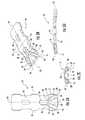
- FIGS. 1A-Frespectively show top, top isometric, end, side, bottom, and bottom isometric views of the low profile anterior vertebral plate system including a vertebral plate and multiple spike fixation elements, one of the spike fixation elements being in an open or ready position relative to the plate and the other spike fixation element being in the closed or fully inserted position relative to the plate.
- FIGS. 2A-Drespectively show top, isometric, end, and side views of the vertebral plate included in the system shown in FIGS. 1A-F .
- FIGS. 3A-Drespectively show top, isometric, end, and side views of an alternative vertebral plate that can be used with the anterior vertebral plate system, the alternative plate including at least one bone screw hole.
- FIGS. 4A-Crespectively show top, isometric, and side views of the spike fixation element included in the system shown in FIGS. 1A-F .
- FIG. 4Dshows a side view of a spike fixation element for use with the vertebral plate spike fixation system, the spike fixation element being provided with a spike grasping fixture.
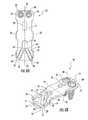
- FIGS. 5A-Brespectively show top and isometric views of the low profile anterior vertebral plate system including a vertebral plate and two pair of opposing spike fixation elements, one member of each pair of the spike fixation elements being in an open or ready position relative to the plate and the other member of each pair of the spike fixation elements being in the closed or fully inserted position relative to the plate.
- FIG. 5Bshows one of the spike fixations elements being configured with an alternative pointed insertion end.
- FIGS. 6A-Brespectively show top and isometric views of the low profile anterior vertebral plate system including a vertebral plate having a pair of spike fixation elements at one end of the plate and a pair of bone screw holes with fully inserted bone screws at the opposing end of the plate, one member of the pair of spike fixation elements being in an open or ready position relative to the plate and the other member of the pair of the spike fixation elements being in the closed or fully inserted position relative to the plate.
- the systemas generally shown at 10 in FIGS. 1A-F , 5 A-B, and 6 A-B includes a low profile anterior vertebral body plate 12 that, when implanted in a patient, can be secured to the underlying bone using at least one bone spike 14 .
- the vertebral body plate 12as shown in FIGS. 1A-F , 2 A-D, 3 A-D, 5 A-B, and 6 A-B can be provided as an elongated, low profile, plate structure that defines at least one and preferably multiple spike slots 16 , which are sized and configured to enable pivotal connection to a corresponding bone spike 14 .
- the bone spike 14as separately shown in FIGS. 4A-D and shown assembled to the bone plate 12 in FIGS. 1A-F , 5 A-B, and 6 A-B is configured to be pivotally connect to a spike connection end 18 of slot 16 .
- the plate 12can be configured to be generally planar; however, the plate preferably will be formed to have arcuate upper and lower surfaces 20 , 22 , arcing along both the longitudinal axis 24 as well as the transverse axis 26 of the plate 12 . This arcing of the plate surface provides a better conformational fit to the anterior surface of the vertebrae to which the plate is to be attached.
- the spike slots 16are defined in the body of the plate 12 to be open-ended slots.
- These open-ended spike slots 16have two slot side walls 28 , 30 extending inwardly from the outer edge of the plate 12 to the spike connection end 18 to form a three-sided open-ended slot.
- the side walls 28 , 30 of the spike slot 16are preferably parallel one to the other, although a spike slot 16 having non-parallel side walls 28 , 30 would still be within the inventor's concept of the system 10 .
- the side walls 28 , 30 of the spike slot 16are of sufficient distance one from the other so as to permit the bone spike 14 to traverse through the spike slot 16 as it pivots about the spike connection end 18 of the spike slot 16 .
- At least one plate portal 34is defined extending through the body of the plate 12 from the upper 20 to the lower 22 surface of the plate. As best shown in FIGS.
- the spike slot 16extends inwardly toward the plate portal 34 and terminates at the spike connection end 18 , which is proximate to the plate portal 34 .
- the portion of the plate 12 between the spike connection end 18 and the adjacent portion of the side wall of the plate portal 34is of a size and configuration appropriate to facilitate the pivotal connection of the bone spike 14 to the plate 12 .
- the spike pivot portion 36 of the plate 12is provided at the spike connection end 18 with a plate pivot surface 38 , which can have a generally convex form to facilitate the rotational movement of the bone spike 14 in its pivotal connection to the plate 12 .
- the bone spike 14as shown in FIGS. 1A-F , 4 A-D, 5 A-B, and 6 A-B can be provided as a generally arcuate or hook-like elongated element having a first end 40 and a second end 42 .
- the first end 40 of the bone spike 14defines an inwardly directed plate connection recess 44 that is sized configured to accept the spike pivot portion 36 of the plate 12 within the connection recess 44 .
- at least a portion of the connection recess 44is configured to have a spike pivot surface 46 having a concave shape that is complementary to the convex shaped plate pivot surface 38 of the plate 12 .
- the upper terminal edge 48 and the lower terminal edge 50 of the plate connection recess 44are spaced apart one from the other to define a recess opening 52 , which is sized to permit passage of the spike pivot portion 36 of the plate 12 into the recess connection 44 of the bone spike 14 .
- the lower terminal edge 50supports a spike securing element 54 , the inner most portion of which is the outermost edge 56 of the spike pivot surface 46 .
- the second end 42 of the bone spike 14can terminate in a sharpened bone penetrating end 58 .
- the sharpened bone penetrating end 58can be provided with a sharpened knife-like configuration suitable for penetrating cortical bone as the bone spike 14 is rotated downward from the plate 12 .
- a spike retention element 59can be provided on the upper or lower surface 60 , 62 near the penetrating end 58 of the spike 14 .
- the spike retention element 59can be configured as a barb, similar to that used on a fish hook, although any configuration for the retention element 59 can be employed that serves to retard the unintentional withdrawal of the fully inserted spike 12 from the bone. Also shown in FIG. 5B is an alternative pointed configuration for the sharpened bone penetrating end 58 . Other configurations of the bone penetrating end 58 can also be employed provided the end 58 is capable of penetrating cortical bone upon the application of manual downward force on the pivotally connected bone spike 14 .
- the bone spike 14has a spike upper surface 60 and a spike lower surface 62 , which due to the generally downward arcuate form of the bone spike 14 will be respectively of a convex shape and concave shape.
- the degree of downward curvature of the generally arcuate shaped bone spike 14is such that when fully inserted into the bone, the bone penetrating end 58 of the bone spike 14 will be positioned within the underlying bone and beneath the body of the plate 12 . When so positioned, the bone spike 14 provides a secure attachment to the underlying bone and thus provides stability to the bone plate system 10 in its attachment to the bone. As shown in FIG.
- the spike upper surface 60can be provided with a tool contact element 64 that is configured to facilitate tool attachment to the spike for the purpose of insertion and/or retraction of the bone spike 14 through cortical bone.
- a tool contact element 64as shown in FIG. 4D , has an eyelet-like configuration; however, the tool contact element 64 can be of any shape or size that is capable of facilitating connection of a tool to the bone spike 14 .
- Non-limiting examples of configurations of the tool contact element 64include an inwardly directed or outwardly directed eyelet, a hook, a textured protrusion, a textured recess, and combinations thereof.
- the spike slot 16can be defined in the body of the plate 12 at an acute angle to the longitudinal axis 24 of the plate 12 .
- This angled position of the spike slot 16which necessarily control the direction of entry of the pivotally attached bone spike 14 , provides additional stability of the plate 12 in both the longitudinal and transverse planes relative to the underlying bone to which the system 10 is attached.
- the system 10includes at least one bone spike 14 ; however, it is preferred that multiple bone spikes be employed to connect the bone plate 12 to underlying bone.
- the system 10can be configured to have at least four spike slots 16 with at least 4 corresponding pivotally connected bone spikes 14 .
- the system 10can also be provided with both bone spike 14 connections and bone screw 68 connections to secure the bone plate 12 to the underlying bone.
- the bone screw holes 70which are defined as through passages in the plate 12 , can be sized and configured to securely receive a respective bone screw 68 .
- the bone screws 68 and bone screw holes 70can be of any known design, including that of a bone screw capable of being locked into position in the bone plate 12 .
- the plate 12can be preassembled with the bone spikes 14 to provide a system 10 that is ready for insertion into a patient and for connection to the anterior surface of the vertebral body without the need for additional locking elements.
- the system 12presents each of the pivotally connected bone spikes 14 in a raised position 72 as shown in FIGS. 1A-F , 5 A-B, and 6 A-B.
- the bone spikes 14can be manually pushed into and through the cortical bone underlying the bone plate 12 , the bone penetrating end 58 of the bone spikes 14 acting to breach the cortical bone and ease the process of insertion of the bone spikes 14 .
- the tool contact element 64 on the upper surface 60 of the bone spike 14can be contacted by an insertion tool to facilitate the insertion process.
- the bone spike 14can be pushed inward into the bone until the pivotal rotation of the bone plate 14 reaches a position relative to the spike pivot portion 36 of the plate 12 where the spike securing element 54 reaches the edge of the plate portal 34 and makes the snap fit connection between the securing element 54 and the plate portal 34 , thus providing a locking connection for the bone spike 14 .
- a system 10is employed that includes both bone spike 14 connections and bone screw 68 connections, as demonstrated in FIGS. 5A-B , bone screws 68 can be inserted through the bone plate 12 and into the underlying bone either before or after the bone spikes 14 have been inserted into the underlying bone.
- the bone spikes 14can be manually pivotally rotated upward with sufficient force to disengage the locking connection of the spike securing element 54 from the edge of the plate portal 34 .
- the bone spike 14can then be easily pivotally rotated out of the underlying bone.
- This retraction of the bone spikes 14can be accomplished, if necessary, by employing a retraction tool suited to connect to the tool contact element 64 on the upper surface 60 of the bone spike 14 .
- the removal of the bone screws 68can be accomplished in a manner and using tools appropriate for the type of bone screw 68 employed.
- the system 10using only bone spikes 14 for connection to the underlying bone requires no additional small locking elements as are used in many conventional efforts to provide a locking method for vertebral plate devices.
- the above described method of use of the system 10can be employed as a method of stabilizing or fixing injured or diseased vertebrae and if necessary, multiple devices or a device, which is elongated beyond the examples depicted herein, can be employed as necessary so as to secure more than two vertebrae together.
- the device as described hereincan be preferably used to attach to the anterior surface of cervical vertebrae and is configured to be capable of stabilizing cervical vertebrae, it is within the inventors' understanding that the plate can be configured and adapted to conform to any implantable surgical plate requirement to provide a low profile plate capable of securing and stabilizing any injured or diseased bone.
- the device 10can be manufactured as integral components by methods known in the art, to include, for example, molding, casting, forming or extruding, and machining processes.
- the componentscan be manufactured using materials having sufficient strength, resiliency and biocompatibility as is well known in the art for such devices.
- suitable materialscan include implant grade metallic materials, such as titanium, cobalt chromium alloys, stainless steel, or other suitable materials for this purpose. It is conceivable that some components of the device can be made from plastics, composite materials, and the like.
- the bone plate 12 and the bone spikes 14can be integrally formed, the connection point of the spikes 14 to the plate 12 being manufactured of a material that can with sufficient force be bent to permit a rotation of the bone spike 14 downward and into underlying bone beneath the plate 12 .
- kitwhich includes at least one of the bone plate systems 10 disclosed herein.
- the kitcan also include additional orthopedic devices and instruments; such as for example, instruments for implanting the system and fixing the bone spikes 14 into bone, removing the bone spikes from the bone, bone screws, instruments for tightening or loosening bone screws, spinal rods, hooks or links and any additional instruments or tools associated therewith.
- additional orthopedic devices and instrumentssuch as for example, instruments for implanting the system and fixing the bone spikes 14 into bone, removing the bone spikes from the bone, bone screws, instruments for tightening or loosening bone screws, spinal rods, hooks or links and any additional instruments or tools associated therewith.
- Such a kitcan be provided with sterile packaging to facilitate opening and immediate use in an operating room.
Landscapes
- Health & Medical Sciences (AREA)
- Orthopedic Medicine & Surgery (AREA)
- Life Sciences & Earth Sciences (AREA)
- Surgery (AREA)
- Neurology (AREA)
- Heart & Thoracic Surgery (AREA)
- Engineering & Computer Science (AREA)
- Biomedical Technology (AREA)
- Nuclear Medicine, Radiotherapy & Molecular Imaging (AREA)
- Medical Informatics (AREA)
- Molecular Biology (AREA)
- Animal Behavior & Ethology (AREA)
- General Health & Medical Sciences (AREA)
- Public Health (AREA)
- Veterinary Medicine (AREA)
- Prostheses (AREA)
- Surgical Instruments (AREA)
Abstract
Description
Claims (23)
Priority Applications (1)
| Application Number | Priority Date | Filing Date | Title |
|---|---|---|---|
| US11/694,403US8920479B2 (en) | 2007-03-30 | 2007-03-30 | Anterior vertebral plate with spike fixation |
Applications Claiming Priority (1)
| Application Number | Priority Date | Filing Date | Title |
|---|---|---|---|
| US11/694,403US8920479B2 (en) | 2007-03-30 | 2007-03-30 | Anterior vertebral plate with spike fixation |
Publications (2)
| Publication Number | Publication Date |
|---|---|
| US20080255620A1 US20080255620A1 (en) | 2008-10-16 |
| US8920479B2true US8920479B2 (en) | 2014-12-30 |
Family
ID=39854441
Family Applications (1)
| Application Number | Title | Priority Date | Filing Date |
|---|---|---|---|
| US11/694,403Expired - Fee RelatedUS8920479B2 (en) | 2007-03-30 | 2007-03-30 | Anterior vertebral plate with spike fixation |
Country Status (1)
| Country | Link |
|---|---|
| US (1) | US8920479B2 (en) |
Cited By (1)
| Publication number | Priority date | Publication date | Assignee | Title |
|---|---|---|---|---|
| US20180049787A1 (en)* | 2016-08-17 | 2018-02-22 | Globus Medical, Inc. | Volar distal radius stabilization system |
Families Citing this family (26)
| Publication number | Priority date | Publication date | Assignee | Title |
|---|---|---|---|---|
| US9039768B2 (en) | 2006-12-22 | 2015-05-26 | Medos International Sarl | Composite vertebral spacers and instrument |
| US20090248092A1 (en) | 2008-03-26 | 2009-10-01 | Jonathan Bellas | Posterior Intervertebral Disc Inserter and Expansion Techniques |
| US8652182B1 (en)* | 2008-10-01 | 2014-02-18 | Spinal U.S.A. | Bone plate with retainer and stop for screw lock |
| US9526620B2 (en) | 2009-03-30 | 2016-12-27 | DePuy Synthes Products, Inc. | Zero profile spinal fusion cage |
| US9107716B2 (en)* | 2009-11-23 | 2015-08-18 | DePuy Synthes Products, Inc. | Flexible maxillo-mandibular fixation device |
| US9393129B2 (en) | 2009-12-10 | 2016-07-19 | DePuy Synthes Products, Inc. | Bellows-like expandable interbody fusion cage |
| US11529241B2 (en) | 2010-09-23 | 2022-12-20 | DePuy Synthes Products, Inc. | Fusion cage with in-line single piece fixation |
| US20120078372A1 (en) | 2010-09-23 | 2012-03-29 | Thomas Gamache | Novel implant inserter having a laterally-extending dovetail engagement feature |
| US20120078373A1 (en) | 2010-09-23 | 2012-03-29 | Thomas Gamache | Stand alone intervertebral fusion device |
| US9248028B2 (en) | 2011-09-16 | 2016-02-02 | DePuy Synthes Products, Inc. | Removable, bone-securing cover plate for intervertebral fusion cage |
| EP2572662A1 (en)* | 2011-09-23 | 2013-03-27 | Zimmer Spine | Stabilization device for vertebrae |
| US9271836B2 (en) | 2012-03-06 | 2016-03-01 | DePuy Synthes Products, Inc. | Nubbed plate |
| US10182921B2 (en) | 2012-11-09 | 2019-01-22 | DePuy Synthes Products, Inc. | Interbody device with opening to allow packing graft and other biologics |
| AU2014365821B2 (en) | 2013-12-20 | 2019-10-03 | Crossroads Extremity Systems, Llc | Polyaxial locking hole |
| WO2015131106A1 (en)* | 2014-02-27 | 2015-09-03 | Surgical Design Innovations | Bone fusion/fixation device and related systems and methods |
| US9820777B2 (en) | 2014-07-09 | 2017-11-21 | DePuy Synthes Products, Inc. | Flexible maxillo-mandibular fixation device |
| JP2017529886A (en) | 2014-07-10 | 2017-10-12 | クロスローズ エクストリミティ システムズ リミテッド ライアビリティ カンパニー | Bone implant and means of insertion |
| US11202626B2 (en) | 2014-07-10 | 2021-12-21 | Crossroads Extremity Systems, Llc | Bone implant with means for multi directional force and means of insertion |
| USD840035S1 (en) | 2015-01-07 | 2019-02-05 | Nextremity Solutions, Inc. | Bone fixation implant |
| WO2017011589A1 (en) | 2015-07-13 | 2017-01-19 | Crossroads Extremity Systems, Llc | Bone plates with dynamic elements |
| US11864753B2 (en) | 2017-02-06 | 2024-01-09 | Crossroads Extremity Systems, Llc | Implant inserter |
| EP3579762B1 (en) | 2017-02-07 | 2024-06-26 | Crossroads Extremity Systems, LLC | Counter-torque implant |
| US10940016B2 (en) | 2017-07-05 | 2021-03-09 | Medos International Sarl | Expandable intervertebral fusion cage |
| US12059183B2 (en) | 2020-07-31 | 2024-08-13 | Crossroads Extremity Systems, Llc | Bone plates with dynamic elements and screws |
| USD961081S1 (en) | 2020-11-18 | 2022-08-16 | Crossroads Extremity Systems, Llc | Orthopedic implant |
| US11813169B1 (en) | 2021-04-27 | 2023-11-14 | Zarija Djurovic | Anatomy preserving shoulder joint replacement device with narrow spherical bearing articulator-interpolation segment |
Citations (21)
| Publication number | Priority date | Publication date | Assignee | Title |
|---|---|---|---|---|
| US4047524A (en)* | 1975-04-28 | 1977-09-13 | Downs Surgical Limited | Surgical implant spinal staple |
| US4434796A (en)* | 1981-04-07 | 1984-03-06 | Vsesojuzny Nauchno-Issledovatelsky I Ispytatelny Institut Meditsinskoi Tekhniki | Surgical staple, a method of and forceps for its removal |
| US4456006A (en)* | 1980-11-10 | 1984-06-26 | Queen's University At Kingston | Contracting bone clip |
| US4531522A (en)* | 1983-06-20 | 1985-07-30 | Ethicon, Inc. | Two-piece tissue fastener with locking top and method for applying same |
| US4651724A (en)* | 1984-05-18 | 1987-03-24 | Technomed Gmk | Bone joining plate |
| US5201737A (en)* | 1991-04-11 | 1993-04-13 | Oswald Leibinger Gmbh | Plate for covering a drill hole in a skull cap and for fixing a cranial bone cover |
| US5662655A (en)* | 1992-07-24 | 1997-09-02 | Laboureau; Jacques Philippe | Osteosynthesis plate-staple |
| US5713899A (en)* | 1995-04-27 | 1998-02-03 | Societe Jbs Sa | Cervical cage designed for the performance of intersomatic arthrodesis |
| US5718705A (en)* | 1996-07-16 | 1998-02-17 | Sammarco; Giacomo J. | Internal fixation plate |
| US5899904A (en)* | 1998-10-19 | 1999-05-04 | Third Milennium Engineering, Llc | Compression locking vertebral body screw, staple, and rod assembly |
| US5941881A (en)* | 1998-01-09 | 1999-08-24 | Medidea, Llc | Bone fastening apparatus and related procedures |
| US6336928B1 (en)* | 1996-10-18 | 2002-01-08 | Depuy France | Device for securing at least two vertebrae |
| US20030100898A1 (en)* | 2001-11-26 | 2003-05-29 | Wellisz Tadeusz Z. | Bone alignment and fixation plate and installation method |
| US20040097935A1 (en)* | 2002-03-12 | 2004-05-20 | Marc Richelsoph | Bone plate and screw retaining mechanism |
| US6746450B1 (en)* | 1999-07-07 | 2004-06-08 | Children's Hospital Medical Center | Spinal correction system |
| US20040153078A1 (en)* | 2003-01-30 | 2004-08-05 | Grinberg Alexander D | Anterior buttress staple |
| US6916320B2 (en)* | 1997-02-11 | 2005-07-12 | Gary K. Michelson | Anterior cervical plate system |
| US20060058796A1 (en)* | 2004-09-14 | 2006-03-16 | Hartdegen Vernon R | Compression brace |
| US20060247681A1 (en)* | 2004-06-28 | 2006-11-02 | Cardio Life Research S.A. | Improved surgical staple |
| US20070123884A1 (en)* | 2005-11-09 | 2007-05-31 | Abdou M S | Bone fixation systems and methods of implantation |
| US20080234750A1 (en)* | 2007-01-31 | 2008-09-25 | Woods Richard W | Anterior vertebral plate with taper lock screw |
- 2007
- 2007-03-30USUS11/694,403patent/US8920479B2/ennot_activeExpired - Fee Related
Patent Citations (22)
| Publication number | Priority date | Publication date | Assignee | Title |
|---|---|---|---|---|
| US4047524A (en)* | 1975-04-28 | 1977-09-13 | Downs Surgical Limited | Surgical implant spinal staple |
| US4456006A (en)* | 1980-11-10 | 1984-06-26 | Queen's University At Kingston | Contracting bone clip |
| US4434796A (en)* | 1981-04-07 | 1984-03-06 | Vsesojuzny Nauchno-Issledovatelsky I Ispytatelny Institut Meditsinskoi Tekhniki | Surgical staple, a method of and forceps for its removal |
| US4531522A (en)* | 1983-06-20 | 1985-07-30 | Ethicon, Inc. | Two-piece tissue fastener with locking top and method for applying same |
| US4651724A (en)* | 1984-05-18 | 1987-03-24 | Technomed Gmk | Bone joining plate |
| US5201737A (en)* | 1991-04-11 | 1993-04-13 | Oswald Leibinger Gmbh | Plate for covering a drill hole in a skull cap and for fixing a cranial bone cover |
| US5662655A (en)* | 1992-07-24 | 1997-09-02 | Laboureau; Jacques Philippe | Osteosynthesis plate-staple |
| US5713899A (en)* | 1995-04-27 | 1998-02-03 | Societe Jbs Sa | Cervical cage designed for the performance of intersomatic arthrodesis |
| US5718705A (en)* | 1996-07-16 | 1998-02-17 | Sammarco; Giacomo J. | Internal fixation plate |
| US6336928B1 (en)* | 1996-10-18 | 2002-01-08 | Depuy France | Device for securing at least two vertebrae |
| US6916320B2 (en)* | 1997-02-11 | 2005-07-12 | Gary K. Michelson | Anterior cervical plate system |
| US5941881A (en)* | 1998-01-09 | 1999-08-24 | Medidea, Llc | Bone fastening apparatus and related procedures |
| US5899904A (en)* | 1998-10-19 | 1999-05-04 | Third Milennium Engineering, Llc | Compression locking vertebral body screw, staple, and rod assembly |
| US6746450B1 (en)* | 1999-07-07 | 2004-06-08 | Children's Hospital Medical Center | Spinal correction system |
| US20030100898A1 (en)* | 2001-11-26 | 2003-05-29 | Wellisz Tadeusz Z. | Bone alignment and fixation plate and installation method |
| US6620165B2 (en)* | 2001-11-26 | 2003-09-16 | Bioplate, Inc. | Bone alignment and fixation plate and installation method |
| US20040097935A1 (en)* | 2002-03-12 | 2004-05-20 | Marc Richelsoph | Bone plate and screw retaining mechanism |
| US20040153078A1 (en)* | 2003-01-30 | 2004-08-05 | Grinberg Alexander D | Anterior buttress staple |
| US20060247681A1 (en)* | 2004-06-28 | 2006-11-02 | Cardio Life Research S.A. | Improved surgical staple |
| US20060058796A1 (en)* | 2004-09-14 | 2006-03-16 | Hartdegen Vernon R | Compression brace |
| US20070123884A1 (en)* | 2005-11-09 | 2007-05-31 | Abdou M S | Bone fixation systems and methods of implantation |
| US20080234750A1 (en)* | 2007-01-31 | 2008-09-25 | Woods Richard W | Anterior vertebral plate with taper lock screw |
Cited By (2)
| Publication number | Priority date | Publication date | Assignee | Title |
|---|---|---|---|---|
| US20180049787A1 (en)* | 2016-08-17 | 2018-02-22 | Globus Medical, Inc. | Volar distal radius stabilization system |
| US10420596B2 (en)* | 2016-08-17 | 2019-09-24 | Globus Medical, Inc. | Volar distal radius stabilization system |
Also Published As
| Publication number | Publication date |
|---|---|
| US20080255620A1 (en) | 2008-10-16 |
Similar Documents
| Publication | Publication Date | Title |
|---|---|---|
| US8920479B2 (en) | Anterior vertebral plate with spike fixation | |
| US8834535B2 (en) | Anterior vertebral plate with closed thread screw | |
| US8403969B2 (en) | Anterior vertebral plate with quick lock screw | |
| US8303633B2 (en) | Dynamic anterior vertebral plate | |
| US12064149B2 (en) | Receiver for minimally invasive surgery | |
| US20080234750A1 (en) | Anterior vertebral plate with taper lock screw | |
| US10492836B2 (en) | Anterior cervical plate | |
| US9629664B2 (en) | Anterior cervical plate | |
| US9730804B2 (en) | Locking spinal fusion device | |
| US20210045783A1 (en) | Bone fixation plate | |
| EP1871251B1 (en) | Spinal fixation locking mechanism | |
| US8920471B2 (en) | Transverse connector | |
| JP4536118B2 (en) | Spine implant with a wide range of multiaxial fastener assemblies | |
| EP1928331B1 (en) | Spinal fixation system having locking and unlocking devices for use with a multi-planar taper lock screw | |
| US9468467B2 (en) | Bone support apparatus | |
| US20080306538A1 (en) | Low profile transverse connector | |
| US20080177314A1 (en) | Modular occipital plate | |
| MX2011000917A (en) | Locking mechanism with two-piece washer. | |
| KR20080107443A (en) | Device for securing the elongated spinal connection element at the bone anchor | |
| US20210401587A1 (en) | Spine implant with cam screws for inhibiting bone anchor backout | |
| US20090198290A1 (en) | Non-Clamping Fastening Mechanism With Anti-Splay Feature | |
| WO2011006155A1 (en) | Transverse connector | |
| US20090030466A1 (en) | Anterior vertebral plate with suture lock | |
| US11246629B2 (en) | Transverse connector | |
| US11857224B2 (en) | Bone plate |
Legal Events
| Date | Code | Title | Description |
|---|---|---|---|
| AS | Assignment | Owner name:K2M, INC., VIRGINIA Free format text:ASSIGNMENT OF ASSIGNORS INTEREST;ASSIGNORS:STRAUSS, KEVIN R.;MCCLINTOCK, LARRY E.;WALLENSTEIN, TODD M.;REEL/FRAME:019653/0877 Effective date:20070507 | |
| AS | Assignment | Owner name:SILICON VALLEY BANK, CALIFORNIA Free format text:SECURITY AGREEMENT;ASSIGNOR:K2M, INC.;REEL/FRAME:023032/0109 Effective date:20090729 Owner name:SILICON VALLEY BANK,CALIFORNIA Free format text:SECURITY AGREEMENT;ASSIGNOR:K2M, INC.;REEL/FRAME:023032/0109 Effective date:20090729 | |
| AS | Assignment | Owner name:SILICON VALLEY BANK, MASSACHUSETTS Free format text:SECURITY INTEREST;ASSIGNORS:K2M, INC.;K2M HOLDING, INC.;K2M UK LIMITED;REEL/FRAME:029489/0327 Effective date:20121029 | |
| AS | Assignment | Owner name:K2M, INC., VIRGINIA Free format text:TERMINATION;ASSIGNOR:SILICON VALLEY BANK;REEL/FRAME:030918/0426 Effective date:20121029 | |
| AS | Assignment | Owner name:SILICON VALLEY BANK, CALIFORNIA Free format text:FIRST AMENDMENT TO PATENT SECURITY AGREEMENT;ASSIGNORS:K2M, INC.;K2M UNLIMITED;K2M HOLDINGS, INC.;REEL/FRAME:034034/0097 Effective date:20141021 | |
| STCF | Information on status: patent grant | Free format text:PATENTED CASE | |
| AS | Assignment | Owner name:SILICON VALLEY BANK, AS ADMINISTRATIVE AGENT, CALIFORNIA Free format text:THIRD AMENDMENT TO PATENT SECURITY AGREEMENT;ASSIGNORS:K2M, INC.;K2M HOLDINGS, INC.;K2M UK LIMITED;REEL/FRAME:039627/0659 Effective date:20160808 Owner name:SILICON VALLEY BANK, AS ADMINISTRATIVE AGENT, CALI Free format text:THIRD AMENDMENT TO PATENT SECURITY AGREEMENT;ASSIGNORS:K2M, INC.;K2M HOLDINGS, INC.;K2M UK LIMITED;REEL/FRAME:039627/0659 Effective date:20160808 | |
| FEPP | Fee payment procedure | Free format text:ENTITY STATUS SET TO UNDISCOUNTED (ORIGINAL EVENT CODE: BIG.) | |
| MAFP | Maintenance fee payment | Free format text:PAYMENT OF MAINTENANCE FEE, 4TH YEAR, LARGE ENTITY (ORIGINAL EVENT CODE: M1551) Year of fee payment:4 | |
| AS | Assignment | Owner name:K2M UK LIMITED, UNITED KINGDOM Free format text:RELEASE BY SECURED PARTY;ASSIGNOR:SILICON VALLEY BANK;REEL/FRAME:047496/0001 Effective date:20181109 Owner name:K2M HOLDINGS, INC., VIRGINIA Free format text:RELEASE BY SECURED PARTY;ASSIGNOR:SILICON VALLEY BANK;REEL/FRAME:047496/0001 Effective date:20181109 Owner name:K2M, INC., VIRGINIA Free format text:RELEASE BY SECURED PARTY;ASSIGNOR:SILICON VALLEY BANK;REEL/FRAME:047496/0001 Effective date:20181109 | |
| FEPP | Fee payment procedure | Free format text:MAINTENANCE FEE REMINDER MAILED (ORIGINAL EVENT CODE: REM.); ENTITY STATUS OF PATENT OWNER: LARGE ENTITY | |
| LAPS | Lapse for failure to pay maintenance fees | Free format text:PATENT EXPIRED FOR FAILURE TO PAY MAINTENANCE FEES (ORIGINAL EVENT CODE: EXP.); ENTITY STATUS OF PATENT OWNER: LARGE ENTITY | |
| STCH | Information on status: patent discontinuation | Free format text:PATENT EXPIRED DUE TO NONPAYMENT OF MAINTENANCE FEES UNDER 37 CFR 1.362 | |
| FP | Lapsed due to failure to pay maintenance fee | Effective date:20221230 |