US8920473B2 - Posterior functionally dynamic stabilization system - Google Patents
Posterior functionally dynamic stabilization systemDownload PDFInfo
- Publication number
- US8920473B2 US8920473B2US11/952,575US95257507AUS8920473B2US 8920473 B2US8920473 B2US 8920473B2US 95257507 AUS95257507 AUS 95257507AUS 8920473 B2US8920473 B2US 8920473B2
- Authority
- US
- United States
- Prior art keywords
- coupler
- flexible
- rigid
- flexible coupler
- sleeve
- Prior art date
- Legal status (The legal status is an assumption and is not a legal conclusion. Google has not performed a legal analysis and makes no representation as to the accuracy of the status listed.)
- Active, expires
Links
Images


Classifications
- A—HUMAN NECESSITIES
- A61—MEDICAL OR VETERINARY SCIENCE; HYGIENE
- A61B—DIAGNOSIS; SURGERY; IDENTIFICATION
- A61B17/00—Surgical instruments, devices or methods
- A61B17/56—Surgical instruments or methods for treatment of bones or joints; Devices specially adapted therefor
- A61B17/58—Surgical instruments or methods for treatment of bones or joints; Devices specially adapted therefor for osteosynthesis, e.g. bone plates, screws or setting implements
- A61B17/68—Internal fixation devices, including fasteners and spinal fixators, even if a part thereof projects from the skin
- A61B17/70—Spinal positioners or stabilisers, e.g. stabilisers comprising fluid filler in an implant
- A61B17/7001—Screws or hooks combined with longitudinal elements which do not contact vertebrae
- A61B17/7002—Longitudinal elements, e.g. rods
- A61B17/7019—Longitudinal elements having flexible parts, or parts connected together, such that after implantation the elements can move relative to each other
- A61B17/7026—Longitudinal elements having flexible parts, or parts connected together, such that after implantation the elements can move relative to each other with a part that is flexible due to its form
- A61B17/7029—Longitudinal elements having flexible parts, or parts connected together, such that after implantation the elements can move relative to each other with a part that is flexible due to its form the entire longitudinal element being flexible
- A—HUMAN NECESSITIES
- A61—MEDICAL OR VETERINARY SCIENCE; HYGIENE
- A61B—DIAGNOSIS; SURGERY; IDENTIFICATION
- A61B17/00—Surgical instruments, devices or methods
- A61B17/56—Surgical instruments or methods for treatment of bones or joints; Devices specially adapted therefor
- A61B17/58—Surgical instruments or methods for treatment of bones or joints; Devices specially adapted therefor for osteosynthesis, e.g. bone plates, screws or setting implements
- A61B17/68—Internal fixation devices, including fasteners and spinal fixators, even if a part thereof projects from the skin
- A61B17/70—Spinal positioners or stabilisers, e.g. stabilisers comprising fluid filler in an implant
- A—HUMAN NECESSITIES
- A61—MEDICAL OR VETERINARY SCIENCE; HYGIENE
- A61B—DIAGNOSIS; SURGERY; IDENTIFICATION
- A61B17/00—Surgical instruments, devices or methods
- A61B17/16—Instruments for performing osteoclasis; Drills or chisels for bones; Trepans
- A61B17/17—Guides or aligning means for drills, mills, pins or wires
- A61B17/1739—Guides or aligning means for drills, mills, pins or wires specially adapted for particular parts of the body
- A61B17/1757—Guides or aligning means for drills, mills, pins or wires specially adapted for particular parts of the body for the spine
- A—HUMAN NECESSITIES
- A61—MEDICAL OR VETERINARY SCIENCE; HYGIENE
- A61B—DIAGNOSIS; SURGERY; IDENTIFICATION
- A61B17/00—Surgical instruments, devices or methods
- A61B17/56—Surgical instruments or methods for treatment of bones or joints; Devices specially adapted therefor
- A61B17/58—Surgical instruments or methods for treatment of bones or joints; Devices specially adapted therefor for osteosynthesis, e.g. bone plates, screws or setting implements
- A61B17/68—Internal fixation devices, including fasteners and spinal fixators, even if a part thereof projects from the skin
- A61B17/70—Spinal positioners or stabilisers, e.g. stabilisers comprising fluid filler in an implant
- A61B17/7001—Screws or hooks combined with longitudinal elements which do not contact vertebrae
- A61B17/7002—Longitudinal elements, e.g. rods
- A61B17/7004—Longitudinal elements, e.g. rods with a cross-section which varies along its length
- A61B17/7007—Parts of the longitudinal elements, e.g. their ends, being specially adapted to fit around the screw or hook heads
- A—HUMAN NECESSITIES
- A61—MEDICAL OR VETERINARY SCIENCE; HYGIENE
- A61B—DIAGNOSIS; SURGERY; IDENTIFICATION
- A61B17/00—Surgical instruments, devices or methods
- A61B17/56—Surgical instruments or methods for treatment of bones or joints; Devices specially adapted therefor
- A61B17/58—Surgical instruments or methods for treatment of bones or joints; Devices specially adapted therefor for osteosynthesis, e.g. bone plates, screws or setting implements
- A61B17/68—Internal fixation devices, including fasteners and spinal fixators, even if a part thereof projects from the skin
- A61B17/70—Spinal positioners or stabilisers, e.g. stabilisers comprising fluid filler in an implant
- A61B17/7001—Screws or hooks combined with longitudinal elements which do not contact vertebrae
- A61B17/7002—Longitudinal elements, e.g. rods
- A61B17/701—Longitudinal elements with a non-circular, e.g. rectangular, cross-section
- A—HUMAN NECESSITIES
- A61—MEDICAL OR VETERINARY SCIENCE; HYGIENE
- A61B—DIAGNOSIS; SURGERY; IDENTIFICATION
- A61B17/00—Surgical instruments, devices or methods
- A61B17/56—Surgical instruments or methods for treatment of bones or joints; Devices specially adapted therefor
- A61B17/58—Surgical instruments or methods for treatment of bones or joints; Devices specially adapted therefor for osteosynthesis, e.g. bone plates, screws or setting implements
- A61B17/68—Internal fixation devices, including fasteners and spinal fixators, even if a part thereof projects from the skin
- A61B17/70—Spinal positioners or stabilisers, e.g. stabilisers comprising fluid filler in an implant
- A61B17/7001—Screws or hooks combined with longitudinal elements which do not contact vertebrae
- A61B17/7002—Longitudinal elements, e.g. rods
- A61B17/7019—Longitudinal elements having flexible parts, or parts connected together, such that after implantation the elements can move relative to each other
- A61B17/7023—Longitudinal elements having flexible parts, or parts connected together, such that after implantation the elements can move relative to each other with a pivot joint
- A—HUMAN NECESSITIES
- A61—MEDICAL OR VETERINARY SCIENCE; HYGIENE
- A61B—DIAGNOSIS; SURGERY; IDENTIFICATION
- A61B17/00—Surgical instruments, devices or methods
- A61B17/56—Surgical instruments or methods for treatment of bones or joints; Devices specially adapted therefor
- A61B17/58—Surgical instruments or methods for treatment of bones or joints; Devices specially adapted therefor for osteosynthesis, e.g. bone plates, screws or setting implements
- A61B17/68—Internal fixation devices, including fasteners and spinal fixators, even if a part thereof projects from the skin
- A61B17/70—Spinal positioners or stabilisers, e.g. stabilisers comprising fluid filler in an implant
- A61B17/7001—Screws or hooks combined with longitudinal elements which do not contact vertebrae
- A61B17/7002—Longitudinal elements, e.g. rods
- A61B17/7019—Longitudinal elements having flexible parts, or parts connected together, such that after implantation the elements can move relative to each other
- A61B17/7025—Longitudinal elements having flexible parts, or parts connected together, such that after implantation the elements can move relative to each other with a sliding joint
- A—HUMAN NECESSITIES
- A61—MEDICAL OR VETERINARY SCIENCE; HYGIENE
- A61B—DIAGNOSIS; SURGERY; IDENTIFICATION
- A61B17/00—Surgical instruments, devices or methods
- A61B17/56—Surgical instruments or methods for treatment of bones or joints; Devices specially adapted therefor
- A61B17/58—Surgical instruments or methods for treatment of bones or joints; Devices specially adapted therefor for osteosynthesis, e.g. bone plates, screws or setting implements
- A61B17/68—Internal fixation devices, including fasteners and spinal fixators, even if a part thereof projects from the skin
- A61B17/70—Spinal positioners or stabilisers, e.g. stabilisers comprising fluid filler in an implant
- A61B17/7001—Screws or hooks combined with longitudinal elements which do not contact vertebrae
- A61B17/7002—Longitudinal elements, e.g. rods
- A61B17/7019—Longitudinal elements having flexible parts, or parts connected together, such that after implantation the elements can move relative to each other
- A61B17/7026—Longitudinal elements having flexible parts, or parts connected together, such that after implantation the elements can move relative to each other with a part that is flexible due to its form
- A61B17/7028—Longitudinal elements having flexible parts, or parts connected together, such that after implantation the elements can move relative to each other with a part that is flexible due to its form the flexible part being a coil spring
- A—HUMAN NECESSITIES
- A61—MEDICAL OR VETERINARY SCIENCE; HYGIENE
- A61B—DIAGNOSIS; SURGERY; IDENTIFICATION
- A61B17/00—Surgical instruments, devices or methods
- A61B17/56—Surgical instruments or methods for treatment of bones or joints; Devices specially adapted therefor
- A61B17/58—Surgical instruments or methods for treatment of bones or joints; Devices specially adapted therefor for osteosynthesis, e.g. bone plates, screws or setting implements
- A61B17/68—Internal fixation devices, including fasteners and spinal fixators, even if a part thereof projects from the skin
- A61B17/70—Spinal positioners or stabilisers, e.g. stabilisers comprising fluid filler in an implant
- A61B17/7074—Tools specially adapted for spinal fixation operations other than for bone removal or filler handling
- A61B17/7076—Tools specially adapted for spinal fixation operations other than for bone removal or filler handling for driving, positioning or assembling spinal clamps or bone anchors specially adapted for spinal fixation
- A61B17/7077—Tools specially adapted for spinal fixation operations other than for bone removal or filler handling for driving, positioning or assembling spinal clamps or bone anchors specially adapted for spinal fixation for moving bone anchors attached to vertebrae, thereby displacing the vertebrae
- A61B17/708—Tools specially adapted for spinal fixation operations other than for bone removal or filler handling for driving, positioning or assembling spinal clamps or bone anchors specially adapted for spinal fixation for moving bone anchors attached to vertebrae, thereby displacing the vertebrae with tubular extensions coaxially mounted on the bone anchors
- A—HUMAN NECESSITIES
- A61—MEDICAL OR VETERINARY SCIENCE; HYGIENE
- A61B—DIAGNOSIS; SURGERY; IDENTIFICATION
- A61B17/00—Surgical instruments, devices or methods
- A61B17/56—Surgical instruments or methods for treatment of bones or joints; Devices specially adapted therefor
- A61B17/58—Surgical instruments or methods for treatment of bones or joints; Devices specially adapted therefor for osteosynthesis, e.g. bone plates, screws or setting implements
- A61B17/88—Osteosynthesis instruments; Methods or means for implanting or extracting internal or external fixation devices
- A61B17/8863—Apparatus for shaping or cutting osteosynthesis equipment by medical personnel
- A—HUMAN NECESSITIES
- A61—MEDICAL OR VETERINARY SCIENCE; HYGIENE
- A61B—DIAGNOSIS; SURGERY; IDENTIFICATION
- A61B17/00—Surgical instruments, devices or methods
- A61B17/56—Surgical instruments or methods for treatment of bones or joints; Devices specially adapted therefor
- A61B17/58—Surgical instruments or methods for treatment of bones or joints; Devices specially adapted therefor for osteosynthesis, e.g. bone plates, screws or setting implements
- A61B17/88—Osteosynthesis instruments; Methods or means for implanting or extracting internal or external fixation devices
- A61B17/8897—Guide wires or guide pins
- A—HUMAN NECESSITIES
- A61—MEDICAL OR VETERINARY SCIENCE; HYGIENE
- A61B—DIAGNOSIS; SURGERY; IDENTIFICATION
- A61B17/00—Surgical instruments, devices or methods
- A61B17/56—Surgical instruments or methods for treatment of bones or joints; Devices specially adapted therefor
- A61B17/58—Surgical instruments or methods for treatment of bones or joints; Devices specially adapted therefor for osteosynthesis, e.g. bone plates, screws or setting implements
- A61B17/68—Internal fixation devices, including fasteners and spinal fixators, even if a part thereof projects from the skin
- A61B2017/681—Alignment, compression, or distraction mechanisms
- A61B2019/307—
- A61B2019/461—
- A—HUMAN NECESSITIES
- A61—MEDICAL OR VETERINARY SCIENCE; HYGIENE
- A61B—DIAGNOSIS; SURGERY; IDENTIFICATION
- A61B90/00—Instruments, implements or accessories specially adapted for surgery or diagnosis and not covered by any of the groups A61B1/00 - A61B50/00, e.g. for luxation treatment or for protecting wound edges
- A61B90/03—Automatic limiting or abutting means, e.g. for safety
- A61B2090/037—Automatic limiting or abutting means, e.g. for safety with a frangible part, e.g. by reduced diameter
- A—HUMAN NECESSITIES
- A61—MEDICAL OR VETERINARY SCIENCE; HYGIENE
- A61B—DIAGNOSIS; SURGERY; IDENTIFICATION
- A61B90/00—Instruments, implements or accessories specially adapted for surgery or diagnosis and not covered by any of the groups A61B1/00 - A61B50/00, e.g. for luxation treatment or for protecting wound edges
- A61B90/06—Measuring instruments not otherwise provided for
- A61B2090/061—Measuring instruments not otherwise provided for for measuring dimensions, e.g. length
Definitions
- the present inventionrelates to devices and methods for treating spinal conditions, and specifically to spinal stabilization systems for controlling or restricting relative motion between vertebrae.
- the spineincludes a series of joints known as motion segment units. Each unit represents the smallest component of the spine that exhibits a kinematic behavior characteristic of the entire spine.
- the motion segment unitis capable of flexion, extension, lateral bending, and translation.
- the components of each motion segment unitinclude two adjacent vertebrae, the corresponding apophyseal joints, an intervertebral disc, and connecting ligamentous tissue, with each component of the motion segment unit contributing to the mechanical stability of the joint.
- the intervertebral discs that separate adjacent vertebraeprovide stiffness that helps to restrain relative motion of the vertebrae in flexion, extension, axial rotation, and lateral bending.
- a damaged discmay provide inadequate stiffness, which may result in excessive relative vertebral motion when the spine is under a given load, causing pain and further damage to the disc.
- treatmentmay include fusion, discectomy, and/or a laminectomy.
- fusionresults in a permanent, rigid fixation with irreversible loss of range of motion at fused vertebral levels.
- loss of mobility at the fused levelscauses stress to be transferred to other neighboring motion segments, which can cause or accelerate degeneration of those segments.
- fusionoften does not alleviate some or all of the pain.
- the present disclosureprovides a functionally dynamic stabilization unit and system for treatment of spinal instability due to, for example, injury, trauma, or degenerative disc disease (DDD).
- Each unit, and collectively, the systemis configured to control flexion, extension, and translation of affected vertebrae, thereby stabilizing the vertebral segments by restoring normal function. This is achieved by providing a unit and system that allow for lateral bending, axial compression, rotation, anterior segmental height adjustment, and posterior segmental height adjustment.
- the unit and systemprovide sufficient segmental stiffness, while also controlling the range of motion to stabilize the vertebral segments.
- the systemmimics the natural movement of the normal spine.
- the systemis configured to allow adjustment over time, revision surgery (e.g., fusion), and percutaneous implantation.
- a functionally dynamic spinal stabilization systemmay comprise a flexible coupler and can include a cylindrical body portion including one or more slots in the wall of the cylindrical body.
- the systemcan further include a pair of gripping arms for attachment to bone anchors, the arms being located at opposed ends of the coupler.
- the flexible couplermay also include an internal range-of-motion limiting mechanism configured to limit motion of the flexible coupler in bending, compression, and tension.
- the systemcan further comprise a pair of bone anchors configured to cooperate with the gripping arms for attachment to bone tissue.
- the systemfurther includes a rigid coupler having a pair of gripping arms for attachment to bone anchors.
- the armscan be located at opposed ends of the coupler.
- this couplerdoes not allow extension or compression. Rather, the coupler promotes fusion by preventing motion at this segment.
- the methodcan comprise attaching a first bone anchor to a vertebra and attaching a second bone anchor to an adjacent vertebrae.
- a flexible couplermay then be attached to the first and second bone anchors.
- the flexible couplercan include a cylindrical body portion having one or more slots in the wall of the cylindrical body and an internal range-of-motion limiting mechanism configured to limit motion of the flexible coupler in bending, compression, and tension.
- the methodcan include producing at least one incision over at least two adjacent vertebrae to be treated and positioning at least two wires such that each wire separately contacts a pedicle of one the at least two vertebrae.
- a screwmay be secured to each vertebrae, and the distance between the screws inserted into two adjacent vertebrae is measured.
- a flexible coupler to be attached to the screwsis selected, and the length of the flexible coupler is adjusted based on the distance measured.
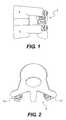
- FIG. 1illustrates a side perspective view of an implanted functionally dynamic stabilization system.
- FIG. 2illustrates a top view of the implanted functionally dynamic stabilization system of FIG. 1 , including two stabilization units on opposite sides of the spine.
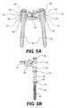
- FIG. 3illustrates a posterior view of the system of FIGS. 1-2 .
- FIG. 4Aillustrates a perspective view of one stabilization unit of the system of FIGS. 1-3 .
- FIG. 4Billustrates a side view of a portion of a flexible coupler used in the stabilization unit of FIG. 4A .
- FIG. 4Cillustrates a top view of the flexible coupler of FIG. 4B .
- FIG. 5Aillustrates a cross-sectional view of the unit of FIG. 4A .
- FIG. 5Billustrates an exploded view of a portion of the stabilization unit of FIG. 4A .
- FIG. 6illustrates an exploded view of the flexible coupler of FIGS. 4B-4C .
- FIG. 7Aillustrates a perspective view of a portion of the flexible coupler of FIGS. 4B and 4C .
- FIG. 7Billustrates a perspective view of a section of the portion of the flexible coupler of FIG. 7A .
- FIG. 8Aillustrates a cross-sectional view of the flexible coupler of FIG. 4B in a resting state.
- FIG. 8Billustrates a cross-sectional view of the flexible coupler of FIG. 4B in a fully expanded state.
- FIG. 8Cillustrates a cross-sectional view of the flexible coupler of FIG. 4B in a fully compressed state.
- FIG. 8Dillustrates an enlarged view of a portion of the flexible coupler of FIG. 8A in a resting state.
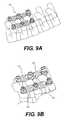
- FIG. 9Aillustrates a perspective view of another embodiment of an implanted functionally dynamic stabilization system.
- FIG. 9Billustrates an enlarged view of the implanted system of FIG. 9A .
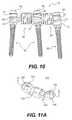
- FIG. 10illustrates a side view of a portion of the system of FIGS. 9A-9B .
- FIG. 11Aillustrates a perspective view of a rigid coupler that may be used with the stabilization systems of the present disclosure.
- FIG. 11Billustrates a cross-sectional view of the rigid coupler of FIG. 11A , taken along line A-A.
- FIG. 11Cillustrates a side cross-sectional view of an alternative embodiment of a rigid coupler that may be used with the stabilization systems of the present disclosure.
- FIG. 12illustrates a perspective view of a modular, multi-segmental stabilization system, according to another embodiment of the disclosure.
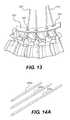
- FIG. 13illustrates a perspective view of a wire template and K-wires used to facilitate implantation of the spinal stabilization systems of the present disclosure.
- FIG. 14Aillustrates a perspective view of a set of extension rods used to facilitate implantation of bone anchors using the methods of the present disclosure.
- FIG. 14Billustrates a partial cutaway view of one of the extension rods of FIG. 14A connected to a bone anchor.
- FIG. 15illustrates a perspective view of a caliper.
- FIG. 16illustrates a perspective view of an alternative set of extension rods according to the present disclosure.
- FIG. 17illustrates a perspective view of an instrument for adjusting the length of a flexible coupler.
- FIG. 18Aillustrates a perspective view of a nut that may be used to secure stabilization units of the present disclosure.
- FIG. 18Billustrates a partial cutaway view of the nut of FIG. 18B coupled to the insertion tool of FIG. 19 .
- FIG. 19illustrates a perspective view of an insertion tool
- the present disclosureprovides a functionally dynamic stabilization unit and a system incorporating functionally dynamic stabilization units for treatment of spinal instability.
- the present disclosurefurther provides minimally-invasive methods for implanting spinal stabilization systems, as well as instruments that will facilitate these methods.
- the unit, system, and methods of the present disclosuremay be used to treat spinal pathologies caused by, for example, injury, trauma, or degenerative disc disease (DDD).
- the stabilization unit and systemscomprising such units are configured to control flexion, extension and translation of an affected unstable vertebral area, thereby stabilizing vertebral segments and restoring normal function. This is achieved by providing a unit and system that allow for lateral bending, axial compression, rotation, anterior segmental height adjustment, and posterior segmental height adjustment on the spine.
- the unit and systemprovide sufficient segmental stiffness within a patient's neutral or active zone, while also limiting or controlling range of motion outside a desired zone. In use, the system mimics the natural movement of the normal spine.
- the systemis configured to allow adjustment over time, revision surgery, and percutaneous delivery or implantation.
- FIG. 1shows an embodiment of a functionally dynamic stabilization system 8 , implanted between adjacent vertebrae 2 , 4 .
- FIG. 2illustrates a top view of an implanted functionally dynamic stabilization system
- FIG. 3illustrates a posterior view of the system 8 of FIGS. 1-2 .
- the system 8can include one or more flexible stabilization units 10 that can be implanted on a posterior portion of the spine to stabilize affected vertebrae 2 , 4 .
- each functionally dynamic stabilization unit 10may comprise a flexible coupler 20 connected to at least one bone anchor 50 , such as a pedicle screw or bone screw.
- the coupler 20may comprise a flexible body 22 including slots 24 and openings 26 .
- the flexible body 22may include, at one end, a gripping arm 30 having an opening 32 for insertion of a bone anchor 50 , and at an opposite end a second gripping arm 40 , also having an opening 33 for receiving a bone anchor 50 .
- the gripping arms 30 , 40may be integrally formed with the body 22 or may be detachably connected to the body 22 .
- one end of the gripping arm 40may be threaded for connection to the flexible body 22 via, for example, a sleeve 90 in the flexible body 22 , as shown in FIG. 6 .
- Each gripping arm 30 , 40 of the coupler 20can include, on one side, a concavely-shaped cavity 34 , 44 configured to seat against a semi-spherical ball bearing 60 , shown in FIGS. 5A-5B , and 6 .
- the ball bearing 60can have a through-hole, allowing it to fit over the bone anchor 50 .
- the bone anchor 50may have an elongate, threaded shaft 52 extending into a flange 56 that connects to a head portion 54 upon which the ball bearing 60 may be placed.
- the flange 56may further include serrations 57 to facilitate anchorage to bone tissue and reduce loosening of the anchor 50 over time.
- the bone anchor 50may be, for example, a pedicle screw.
- the bone anchor 50can be cannulated to enable the unit 10 or system 8 to be percutaneously delivered.
- the concavely-shaped cavities 34 , 44allow the gripping arms to slide or rotate with respect to the bearing 60 , thereby enabling the gripping arms 30 , 40 to move relative to the bone anchor 50 .
- Other appropriate structuresmay be used to connect the flexible body 22 to the bone anchors 50 while permitting relative movement between the two.
- a washer 70may be placed onto the screw 50 and against the flange 56 or nut 80 .
- the washer 70can be configured and shaped to lie against the ball bearing 60 .
- An assembled functionally dynamic stabilization unit 10would further include a nut 80 screwed onto the head portion 54 of the screw 50 to secure the components to one another, as illustrated in FIGS. 4A and 5A .
- Each functionally dynamic stabilization unit 10is configured to allow a range of motion or displacement of between 1.5 and 3.0 mm, where displacement may be measured from the center of a first pedicle screw connected to a first gripping arm 30 to the center of a second pedicle screw connected to the second gripping arm 40 .
- This displacement or range of motionmay be achieved, for example, through rotation, extension, or translation.
- FIG. 6illustrates an exploded view of the flexible coupler of FIGS. 4A-4C .
- one of the gripping arms 40may be removably attached to the coupler 20 .
- the coupler 20can include a threaded opening 28 for securing the second gripping arm 40 , and other components, to the coupler 20 .
- there may be a sleeve 90having an opening 92 at one end and including a threaded rim 94 around the opening 92 for threadably connecting to the coupler body 22 .
- the sleeve 90can be configured to reside within the coupler body 22 and to receive and cooperate with a pin 100 .
- the pin 100can comprise an elongate body 102 with a threaded end, the body 102 extending into a semispherical head region 104 and including a skirt or shoulder region 106 .
- the sleeve 90 and pin 100form an extension and compression stop within the coupler body 22 , functioning to limit range of motion of the flexible coupler 20 to the patient's neutral or active zone.
- the rim 92 of the sleeve 90may be threaded to engage the threaded end 46 of the detachable second gripping arm 40 .
- the overall length of the coupler 20may be adjusted by varying the amount of threading of the second gripping arm 40 into the sleeve 90 (i.e., varying the number of rotations of the arm 40 into the sleeve 90 ).
- the threaded end 46 of the detachable second gripping arm 40may extend into a plurality of compressible finger projections 43 , each projection 43 terminating at a flanged lip 47 .
- the flanged lip 47serves as a locking mechanism, preventing the second gripping arm 40 from being unscrewed from the sleeve 90 after assembly.
- the threaded end 46may also include a well 48 for receiving an elastomeric plug 110 , as shown in FIG. 8C .
- the elastomeric plug 110may be formed of a soft, compliant plastic material such as, for example, silicone, polyethylene, or polyethyletherketone (PEEK).
- PEEKpolyethyletherketone
- the plug 110interacts with the threaded opening 92 , reducing the slack or play between the arm 40 and the sleeve 90 .
- Other suitable structuresthat permit adjustment of the length of the flexible body while providing control of the amount of compression and extension of the flexible body may also be used.
- a gripping armcan be attached at a friction fit, a telescoping connection, or using a ratchet mechanism.
- the coupler body 22may include a cylindrical body comprised of a series of coil units 22 A.
- the series of coil units 22when connected to one another to form a stepwise series of slots 24 , whereby each slot 24 terminates at an opening 26 of the flexible body 22 .
- the series of coil units 22 Acan be formed from a single piece of material such that the units 22 A are integrally connected with one another.
- the coil units 22 Acan be etched or cut from a single, tubular piece of material.
- one or more coil units 22 Acan be formed individually and stacked upon one another. The stacked coil units 22 A can be connected to one another, for example, by welding or through mechanical connections.
- the coupler body 22may vary in degree of stiffness based on the height, width, distance or angle between two adjacent slots 24 and the number of units 22 A forming the coupler body 22 . Further, one or more units 22 A may be formed from different materials so as to vary the mechanical properties of the body 22 . In addition, the dimensions of the units 22 A, slots 24 , and openings 26 can be varied within a single body 22 .
- FIGS. 8A-8Dshow an embodiment of the fully assembled flexible coupler 20 in a resting state ( FIGS. 8A and 8D ), fully-expanded or distracted state ( FIG. 8B ), and a fully compressed state ( FIG. 8C ).
- the pin 100 and sleeve 90are not engaged (i.e., free of resistive forces or encumbrances).
- the fully-expanded or distracted stateFIG.
- the pin head 104having a dimension that is larger than the width of the narrowed opening 98 , abuts the narrowed opening 98 of the sleeve 90 , preventing the flexible coupler body 22 from over expanding.
- the end of the sleeve 90 with the narrowed opening 98abuts the inner edge of the first gripping arm 30 , as shown.
- the cooperation of the sleeve 90 and pin 100 inside the coupler body 22provides a distraction-compression stopping mechanism to control or limit the range of motion that can be offered, preventing not only injury or damage to the affected vertebral segments but also to the functionally dynamic stabilization unit itself.
- Other types of cooperating elementssuch as, for example, a telescoping element or internal piston, may be sued to control or limit the range of motion of the coupler body 22 .
- the functionally dynamic stabilization unit 10may be used alone to stabilize a pair of vertebral segments. Further, if desired, more than one unit 10 may be used in combination to form a multi-level, functionally dynamic stabilization system 12 , as shown in FIGS. 9A and 9B .
- the multi-level, functionally dynamic stabilization system 12may include two or more of the units 10 connected to one another.
- FIG. 10illustrates a side view of the system shown in FIGS. 9A-9B .
- the system 12includes a pair of flexible couplers 20 connected in series.
- the couplers 20are positioned such that the first gripping arm 30 of each coupler 20 is placed around one ball bearing 60 , with a bone anchor 50 and nut 80 securing the combination together. It is understood that more than two couplers 20 may be connected in this manner, and either the first 30 or second 40 gripping arm of any single coupler may be combined with the first 30 or second 40 gripping arm of another coupler 20 on a bone anchor 50 .
- Any number of couplers 20may be implanted either along one side, or on both sides, of a patient's spine. Further, the units 10 may have differing mechanical properties according to the patient's pathology and anatomy.
- the stabilization systems of the present disclosurecan allow fusion of one or more vertebral motion segments, along with functionally dynamic stabilization of other motion segments.
- the stabilization systemmay include a rigid, fusion-promoting coupler 101 , such as the one shown in FIG. 11A .
- the rigid coupler 101can be configured for use with the bone anchors 50 , ball bearings 60 , and washers 70 described previously.
- the rigid coupler 101comprises two components 122 , 124 , each of which extends to a gripping arm 130 , 140 , respectively, in a manner similar to that in the flexible coupler 20 previously described.
- Each of the arms 130 , 140includes an opening 132 for attachment to a bone anchor 50 , in a manner similar to that described with respect to the flexible coupler 20 .
- the two components 122 , 124may be attached to one another to allow adjustment of the length of the rigid coupler 101 .
- the components 122 , 124can include threaded surfaces, and the length of the rigid coupler 101 can be adjusted by twisting one component 122 with respect to the other component 124 , much like the manner previously described for adjusting the length of the flexible coupler 20 .
- Each of the gripping arms 130 , 140can also include, on an underside, a concave cavity 134 , 144 , respectively, configured to seat against a semi-spherical ball bearing 60 .
- the implantation of the rigid coupler 101 to the bone anchors 50is similar to that for the flexible coupler 20 , as previously described.
- a rigid, fusion-promoting coupler 201may be provided.
- the rigid, fusion-promoting coupler 201is similar to rigid coupler 101 except that it may not utilize threaded surfaces of components for adjusting a length of the coupler 201 .
- the rigid coupler 201can be configured for use with the bone anchors 50 , ball bearings 60 , and washers 70 described previously.
- the rigid coupler 201comprises two components 222 , 224 , each of which extends to a gripping arm 230 , 240 , respectively, in a manner similar to that in the flexible coupler 20 previously described.
- Each of the arms 230 , 240includes an opening (not shown) for attachment to a bone anchor 50 , in a manner similar to that described with respect to the flexible coupler 20 .
- Each of the gripping arms 230 , 240can also include, on an underside, a concave cavity 234 , 244 , respectively, configured to seat against a semi-spherical ball bearing 60 .
- the first component 222 and the second component 224may be movable relative to one another to facilitate adjustment of the length of the coupler 201 .
- the component 222may include a cavity 226 configured to receive a fastening element 230 to secure the first component 222 relative to the second component 224 .
- the first and second componentsdo not include threaded surfaces, they may be moved relative to one another by sliding the components rather than twisting. Such an embodiment permits the surgeon to adjust the length of the rigid coupler 201 in situ as necessary.
- the fastening element 230may be any suitable fastening element such as a screw or a nut.
- the fastening element 230may comprise a break-away nut having a first portion configured to fixingly engage the portion 226 of component 222 to fix the position of the first component 222 relative to the second component and a second portion configured to engage an insertion tool for tightening of the first portion to the rigid coupler.
- the second portion of the break-away nutmay be a break-away portion that has a thinner wall or area of lower yield-strength material, and is configured to break when a sufficient torque is applied (i.e., when the nut 230 has been sufficiently tightened).
- An internal surface of cavity 226 and an external surface of the fastening element 230may be provided with threads to facilitate engagement of the cavity 226 with the fastening element 230 .
- the stabilization systemmay include both functionally dynamic, flexible couplers 20 and rigid couplers 101 , thereby providing a modular system that allows the combination of motion preservation and fusion at discrete segments of the patient's spine.
- the surgeonwill have greater flexibility to address the specific needs of the patient. Therefore, one spinal segment may have functionally dynamic stabilization (i.e., non-fusion), while an adjacent segment may have rigid, segmental fixation (i.e., fusion).
- FIG. 12illustrates a multi-segmental system 12 comprising three discreet stabilization units 10 a , 10 b , 10 c utilizing flexible couplers 20 a , 20 b and a rigid coupler 101 .
- the flexible couplers 20 a , 20 b of units 10 a and 10 cincrease the segmental stiffness of the affected motion segment and restrict the range of motion in flexion, extension, lateral bending and rotation, while preserving motion.
- the posterior segmental heightcan be adjusted as well.
- the rigid, fusion-promoting coupler 101 of unit 10 bprovides rigid, segmental fixation, thereby promoting fusion, while utilizing the same type of bone anchors 50 and instruments.
- an implanted systemmay include only functionally dynamic, flexible couplers 20 connected to vertebra with bone anchors 50 , as described above.
- an implanted systemmay include only functionally dynamic, flexible couplers 20 connected to vertebra with bone anchors 50 , as described above.
- the units and systems of the present disclosurecan be implanted using a minimally-invasive, muscle-sparing approach.
- Such approachescan include percutaneous methods or a series of small incisions that minimize tissue damage.
- FIGS. 13-19illustrate exemplary embodiments of insertion instruments that may be provided separately or as a set along with the system.
- a series of K-wires 200are inserted into the pedicles of the patient's spine.
- the K-wires 200may be inserted through a series of small incisions in the patient's back.
- a wire template 202may be provided to assist the surgeon in placement of the incisions and K-wires 200 .
- the wire template 202may include predetermined openings 204 that align with the pedicles of the patient's spine, as illustrated.
- the openings 204may be bilaterally located in line with both pedicles of vertebrae to be treated.
- the templatemay be provided in various sizes to accommodate patients having variations in pedicle spacing.
- the cannulated bone anchors 50may be passed over the K-wires 200 , and using a series of extension rods 220 a , 220 b , 220 c , shown in FIG. 14A , the bone anchors can be implanted within selected vertebra. As shown in FIG. 14B , the extension rods can attach to the head portions 54 of the bone anchors 50 to allow manipulation of the anchors 50 . In addition, a dilatation sleeve (not shown) can be provided, and the extension rods can be passed through the dilation sleeve to access the implantation site.
- the extension rods 220can be used to manipulate the anchors 50 and the attached vertebrae to ascertain the full range of motion in a static condition and with an applied load. Such information may be useful to the surgeon to predict the possible range of corrective motion desirable for that spine segment.
- a caliper 240may also be provided with the instrument set.
- the caliper 240can comprise a pair of pivoting arms 242 , 244 , each arm extending to a finger engaging opening 246 , 248 , respectively, and terminating at an opposite end into a gripping end 250 , 252 , respectively.
- the pivoting arms 242 , 244can be connected via a leaf spring 254 .
- the ends of the arms 242 , 244are configured to provide a reading or measurement of the distance between a pair of adjacent bone anchors 50 using the indicia markings 258 on a backboard 256 .
- the gripping ends 250 , 252can be configured to hold a portion of the ball bearing 60 of each bone anchor 50 . This enables the caliper 240 to function even when the bone anchors 50 are situated in a nonparallel or unique angle relative to one another.
- FIG. 16illustrates various rod extensions 260 that are configured to connect to other components of the anchor, such as the ball bearing 60 , washer 70 , or nut 80 .
- Each of these rod extensions 260enables minimally-invasive or percutaneous manipulation of the respective component.
- a coupler length adjuster 270may be provided to ensure that the coupler length is correct prior to insertion.
- the length adjuster 270may include a body 272 having a pair of grips 271 , between which a coupler 20 , 101 can be held.
- the pair of grips 271form the insertion area 274 for the coupler.
- Within the body 272is a spring-loaded mechanism that exerts biased force against one of the grips 271 .
- the spring-loaded mechanismmay be controlled by turning a knob 280 , thereby twisting the coupler 20 , 101 , and consequently adjusting its length.
- the body 272may further include a window 278 within which there appear indicia 276 indicating the length of the coupler.
- a flexible coupler 20is illustrated, it is understood that the length adjuster 270 is also applicable for use with a rigid coupler 101 .
- FIG. 18Aillustrates an exemplary embodiment of a suitable nut 180 having a break-away portion 182 , connecting an anchor-engaging lower portion 186 to an upper portion 184 .
- the break-away portion 182having a thinner wall or area of lower yield-strength material, is configured to break when a sufficient torque is applied (i.e., when the nut 180 has been sufficiently tightened).
- FIG. 19shows an exemplary insertion tool 290 useful for insertion of the nut 180 .
- the insertion tool 290comprises an elongate body 292 extending from a handle portion 294 to a nut coupling end 296 at an opposite end.
- the coupling end 296may be configured to securely attach to the nut at the upper portion 184 , as shown in FIG. 18B , and the elongate body 292 , with a nut coupled thereto, can be inserted into a previously defined access site to secure the nut 180 to a bone anchor 50 .
- the nut 180will break at break-away portion 182 , leaving the lower portion 186 on a bone anchor and allowing the upper portion 184 to be withdrawn.
- the surgeonmay elect to repeat this process at an adjacent level until all the affected levels of the patient's spine have been treated.
- the entire processmay be done percutaneously and/or with minimal disruption to the surrounding tissue.
Landscapes
- Health & Medical Sciences (AREA)
- Orthopedic Medicine & Surgery (AREA)
- Life Sciences & Earth Sciences (AREA)
- Surgery (AREA)
- Neurology (AREA)
- Heart & Thoracic Surgery (AREA)
- General Health & Medical Sciences (AREA)
- Biomedical Technology (AREA)
- Nuclear Medicine, Radiotherapy & Molecular Imaging (AREA)
- Medical Informatics (AREA)
- Molecular Biology (AREA)
- Animal Behavior & Ethology (AREA)
- Engineering & Computer Science (AREA)
- Public Health (AREA)
- Veterinary Medicine (AREA)
- Dentistry (AREA)
- Oral & Maxillofacial Surgery (AREA)
- Prostheses (AREA)
- Surgical Instruments (AREA)
Abstract
Description
Claims (26)
Priority Applications (3)
| Application Number | Priority Date | Filing Date | Title |
|---|---|---|---|
| US11/952,575US8920473B2 (en) | 2006-12-10 | 2007-12-07 | Posterior functionally dynamic stabilization system |
| US14/585,097US9522018B2 (en) | 2006-12-10 | 2014-12-29 | Posterior functionally dynamic stabilization system |
| US15/383,536US10092329B2 (en) | 2006-12-10 | 2016-12-19 | Posterior functionally dynamic stabilization system |
Applications Claiming Priority (3)
| Application Number | Priority Date | Filing Date | Title |
|---|---|---|---|
| US86934206P | 2006-12-10 | 2006-12-10 | |
| US91436007P | 2007-04-27 | 2007-04-27 | |
| US11/952,575US8920473B2 (en) | 2006-12-10 | 2007-12-07 | Posterior functionally dynamic stabilization system |
Related Child Applications (1)
| Application Number | Title | Priority Date | Filing Date |
|---|---|---|---|
| US14/585,097DivisionUS9522018B2 (en) | 2006-12-10 | 2014-12-29 | Posterior functionally dynamic stabilization system |
Publications (2)
| Publication Number | Publication Date |
|---|---|
| US20080312693A1 US20080312693A1 (en) | 2008-12-18 |
| US8920473B2true US8920473B2 (en) | 2014-12-30 |
Family
ID=39323009
Family Applications (3)
| Application Number | Title | Priority Date | Filing Date |
|---|---|---|---|
| US11/952,575Active2030-06-27US8920473B2 (en) | 2006-12-10 | 2007-12-07 | Posterior functionally dynamic stabilization system |
| US14/585,097ActiveUS9522018B2 (en) | 2006-12-10 | 2014-12-29 | Posterior functionally dynamic stabilization system |
| US15/383,536Active2028-01-10US10092329B2 (en) | 2006-12-10 | 2016-12-19 | Posterior functionally dynamic stabilization system |
Family Applications After (2)
| Application Number | Title | Priority Date | Filing Date |
|---|---|---|---|
| US14/585,097ActiveUS9522018B2 (en) | 2006-12-10 | 2014-12-29 | Posterior functionally dynamic stabilization system |
| US15/383,536Active2028-01-10US10092329B2 (en) | 2006-12-10 | 2016-12-19 | Posterior functionally dynamic stabilization system |
Country Status (14)
| Country | Link |
|---|---|
| US (3) | US8920473B2 (en) |
| EP (2) | EP3216407B1 (en) |
| JP (1) | JP2010512228A (en) |
| KR (1) | KR20090097909A (en) |
| CN (1) | CN102525623B (en) |
| AR (1) | AR064204A1 (en) |
| AU (1) | AU2007333199B2 (en) |
| CA (1) | CA2671868A1 (en) |
| ES (1) | ES2601355T3 (en) |
| HK (1) | HK1244416B (en) |
| IL (1) | IL198962A0 (en) |
| MX (1) | MX2009005843A (en) |
| TW (1) | TW200843691A (en) |
| WO (1) | WO2008073830A1 (en) |
Cited By (6)
| Publication number | Priority date | Publication date | Assignee | Title |
|---|---|---|---|---|
| US20130253584A1 (en)* | 2006-10-19 | 2013-09-26 | Simpirica Spine, Inc. | Methods and systems for laterally stabilized constraint of spinous processes |
| US20150045888A1 (en)* | 2004-02-17 | 2015-02-12 | Gmedelaware 2 Llc | Facet joint replacement instruments and methods |
| US10080589B2 (en) | 2004-03-09 | 2018-09-25 | The Board Of Trustees Of The Leland Stanford Junior University | Methods and systems for constraint of spinous processes with attachment |
| US20210196327A1 (en)* | 2019-12-25 | 2021-07-01 | Apifix Ltd. | Biasing device for spinal device |
| US11583318B2 (en) | 2018-12-21 | 2023-02-21 | Paradigm Spine, Llc | Modular spine stabilization system and associated instruments |
| US20230085446A1 (en)* | 2007-06-22 | 2023-03-16 | Empirical Spine, Inc, | Methods and systems for increasing the bending stiffness of a spinal segment with elongation limit |
Families Citing this family (67)
| Publication number | Priority date | Publication date | Assignee | Title |
|---|---|---|---|---|
| US10258382B2 (en) | 2007-01-18 | 2019-04-16 | Roger P. Jackson | Rod-cord dynamic connection assemblies with slidable bone anchor attachment members along the cord |
| US10729469B2 (en) | 2006-01-09 | 2020-08-04 | Roger P. Jackson | Flexible spinal stabilization assembly with spacer having off-axis core member |
| US7862587B2 (en) | 2004-02-27 | 2011-01-04 | Jackson Roger P | Dynamic stabilization assemblies, tool set and method |
| US20160242816A9 (en) | 2001-05-09 | 2016-08-25 | Roger P. Jackson | Dynamic spinal stabilization assembly with elastic bumpers and locking limited travel closure mechanisms |
| DE10320417A1 (en)* | 2003-05-07 | 2004-12-02 | Biedermann Motech Gmbh | Dynamic anchoring device and dynamic stabilization device for bones, in particular for vertebrae, with such an anchoring device |
| US11241261B2 (en) | 2005-09-30 | 2022-02-08 | Roger P Jackson | Apparatus and method for soft spinal stabilization using a tensionable cord and releasable end structure |
| US7458981B2 (en) | 2004-03-09 | 2008-12-02 | The Board Of Trustees Of The Leland Stanford Junior University | Spinal implant and method for restricting spinal flexion |
| US9216041B2 (en)* | 2009-06-15 | 2015-12-22 | Roger P. Jackson | Spinal connecting members with tensioned cords and rigid sleeves for engaging compression inserts |
| US7901437B2 (en) | 2007-01-26 | 2011-03-08 | Jackson Roger P | Dynamic stabilization member with molded connection |
| US8187307B2 (en) | 2006-10-19 | 2012-05-29 | Simpirica Spine, Inc. | Structures and methods for constraining spinal processes with single connector |
| US8162982B2 (en) | 2006-10-19 | 2012-04-24 | Simpirica Spine, Inc. | Methods and systems for constraint of multiple spine segments |
| US9867640B2 (en) | 2006-12-07 | 2018-01-16 | Nexus Spine, LLC | Press-on pedicle screw assembly |
| US11224463B2 (en) | 2007-01-18 | 2022-01-18 | Roger P. Jackson | Dynamic stabilization connecting member with pre-tensioned flexible core member |
| US8475498B2 (en) | 2007-01-18 | 2013-07-02 | Roger P. Jackson | Dynamic stabilization connecting member with cord connection |
| US8366745B2 (en) | 2007-05-01 | 2013-02-05 | Jackson Roger P | Dynamic stabilization assembly having pre-compressed spacers with differential displacements |
| US9314346B2 (en) | 2007-02-12 | 2016-04-19 | Brigham Young University | Spinal implant |
| US10383660B2 (en) | 2007-05-01 | 2019-08-20 | Roger P. Jackson | Soft stabilization assemblies with pretensioned cords |
| US8048123B2 (en) | 2007-06-05 | 2011-11-01 | Spartek Medical, Inc. | Spine implant with a deflection rod system and connecting linkages and method |
| US8092501B2 (en) | 2007-06-05 | 2012-01-10 | Spartek Medical, Inc. | Dynamic spinal rod and method for dynamic stabilization of the spine |
| US8083772B2 (en) | 2007-06-05 | 2011-12-27 | Spartek Medical, Inc. | Dynamic spinal rod assembly and method for dynamic stabilization of the spine |
| US8048128B2 (en) | 2007-06-05 | 2011-11-01 | Spartek Medical, Inc. | Revision system and method for a dynamic stabilization and motion preservation spinal implantation system and method |
| US8048115B2 (en) | 2007-06-05 | 2011-11-01 | Spartek Medical, Inc. | Surgical tool and method for implantation of a dynamic bone anchor |
| US8114134B2 (en) | 2007-06-05 | 2012-02-14 | Spartek Medical, Inc. | Spinal prosthesis having a three bar linkage for motion preservation and dynamic stabilization of the spine |
| US8021396B2 (en) | 2007-06-05 | 2011-09-20 | Spartek Medical, Inc. | Configurable dynamic spinal rod and method for dynamic stabilization of the spine |
| EP2182864B1 (en) | 2007-06-22 | 2016-06-08 | Empirical Spine, Inc. | Devices for controlled flexion restriction of spinal segments |
| US20100036424A1 (en)* | 2007-06-22 | 2010-02-11 | Simpirica Spine, Inc. | Methods and systems for increasing the bending stiffness and constraining the spreading of a spinal segment |
| EP2047810B1 (en)* | 2007-10-11 | 2011-09-28 | BIEDERMANN MOTECH GmbH | Modular rod system for spinal stabilization |
| US8894687B2 (en) | 2011-04-25 | 2014-11-25 | Nexus Spine, L.L.C. | Coupling system for surgical construct |
| US8057517B2 (en) | 2008-02-26 | 2011-11-15 | Spartek Medical, Inc. | Load-sharing component having a deflectable post and centering spring and method for dynamic stabilization of the spine |
| US8333792B2 (en) | 2008-02-26 | 2012-12-18 | Spartek Medical, Inc. | Load-sharing bone anchor having a deflectable post and method for dynamic stabilization of the spine |
| US8211155B2 (en) | 2008-02-26 | 2012-07-03 | Spartek Medical, Inc. | Load-sharing bone anchor having a durable compliant member and method for dynamic stabilization of the spine |
| US8007518B2 (en) | 2008-02-26 | 2011-08-30 | Spartek Medical, Inc. | Load-sharing component having a deflectable post and method for dynamic stabilization of the spine |
| US8083775B2 (en) | 2008-02-26 | 2011-12-27 | Spartek Medical, Inc. | Load-sharing bone anchor having a natural center of rotation and method for dynamic stabilization of the spine |
| US8267979B2 (en) | 2008-02-26 | 2012-09-18 | Spartek Medical, Inc. | Load-sharing bone anchor having a deflectable post and axial spring and method for dynamic stabilization of the spine |
| US8097024B2 (en) | 2008-02-26 | 2012-01-17 | Spartek Medical, Inc. | Load-sharing bone anchor having a deflectable post and method for stabilization of the spine |
| US8337536B2 (en) | 2008-02-26 | 2012-12-25 | Spartek Medical, Inc. | Load-sharing bone anchor having a deflectable post with a compliant ring and method for stabilization of the spine |
| US8048125B2 (en) | 2008-02-26 | 2011-11-01 | Spartek Medical, Inc. | Versatile offset polyaxial connector and method for dynamic stabilization of the spine |
| WO2009149399A1 (en)* | 2008-06-06 | 2009-12-10 | Simpirica Spine, Inc. | Methods and apparatus for deploying spinous process constraints |
| WO2009149414A1 (en) | 2008-06-06 | 2009-12-10 | Simpirica Spine, Inc. | Methods and apparatus for locking a band |
| AU2010260521C1 (en) | 2008-08-01 | 2013-08-01 | Roger P. Jackson | Longitudinal connecting member with sleeved tensioned cords |
| CA2743721A1 (en) | 2009-02-19 | 2010-08-26 | Anton E. Bowden | Compliant dynamic spinal implant |
| WO2010096829A2 (en)* | 2009-02-23 | 2010-08-26 | Crocker Spinal, L.L.C. | Press-on link for surgical screws |
| WO2010104935A1 (en) | 2009-03-10 | 2010-09-16 | Simpirica Spine, Inc. | Surgical tether apparatus and methods of use |
| WO2010104975A1 (en)* | 2009-03-10 | 2010-09-16 | Simpirica Spine, Inc. | Surgical tether apparatus and methods of use |
| EP2405840B1 (en) | 2009-03-10 | 2024-02-21 | Empirical Spine, Inc. | Surgical tether apparatus |
| US8668719B2 (en)* | 2009-03-30 | 2014-03-11 | Simpirica Spine, Inc. | Methods and apparatus for improving shear loading capacity of a spinal segment |
| US8292927B2 (en)* | 2009-04-24 | 2012-10-23 | Warsaw Orthopedic, Inc. | Flexible articulating spinal rod |
| US8105360B1 (en) | 2009-07-16 | 2012-01-31 | Orthonex LLC | Device for dynamic stabilization of the spine |
| US9157497B1 (en) | 2009-10-30 | 2015-10-13 | Brigham Young University | Lamina emergent torsional joint and related methods |
| CN102695465A (en) | 2009-12-02 | 2012-09-26 | 斯帕泰克医疗股份有限公司 | Low profile spinal prosthesis incorporating a bone anchor having a deflectable post and a compound spinal rod |
| DE102010000339A1 (en) | 2010-02-08 | 2011-08-11 | Aesculap AG, 78532 | Connecting element for a spine stabilization system and spine stabilization system |
| US20110307015A1 (en) | 2010-06-10 | 2011-12-15 | Spartek Medical, Inc. | Adaptive spinal rod and methods for stabilization of the spine |
| AU2011299558A1 (en) | 2010-09-08 | 2013-05-02 | Roger P. Jackson | Dynamic stabilization members with elastic and inelastic sections |
| DE102010060101A1 (en) | 2010-09-20 | 2012-03-22 | Aesculap Ag | Spinal stabilization system and surgical device for temporarily stiffening a flexible intermediate portion of a spinal stabilization system connector |
| US8721566B2 (en) | 2010-11-12 | 2014-05-13 | Robert A. Connor | Spinal motion measurement device |
| WO2012109475A2 (en)* | 2011-02-09 | 2012-08-16 | Redyns Medical Llc | Method and apparatus for attaching an elongated object to bone |
| WO2012177412A2 (en)* | 2011-06-07 | 2012-12-27 | Brigham Young University | Serpentine spinal stability device and associated methods |
| US8430916B1 (en) | 2012-02-07 | 2013-04-30 | Spartek Medical, Inc. | Spinal rod connectors, methods of use, and spinal prosthesis incorporating spinal rod connectors |
| DE102012202750A1 (en) | 2012-02-22 | 2013-08-22 | Aces Gmbh | Dynamic stabilization device for treating degenerative diseases of spinal column, has support- and mating surfaces formed for clamping by load of spring element, and retaining elements movably mounted against each other in direction |
| US9402673B2 (en)* | 2012-09-28 | 2016-08-02 | DePuy Synthes Products, Inc. | Devices and methods for breaking and retaining surgical reduction tabs |
| DE102013110173A1 (en) | 2013-09-16 | 2015-03-19 | Aesculap Ag | Connecting element and spine stabilization system |
| ES2804126T3 (en) | 2014-02-24 | 2021-02-03 | Univ Curtin Tech | Bra |
| FR3018678B1 (en)* | 2014-03-20 | 2016-03-11 | Spineway | SURGICAL ASSEMBLY, BONE ANCHORING SCREW AND DEVICE FOR EXTENSION OF SUCH SCREWS FORMING PART OF SAID SURGICAL ASSEMBLY |
| US9642651B2 (en) | 2014-06-12 | 2017-05-09 | Brigham Young University | Inverted serpentine spinal stability device and associated methods |
| CN108289689A (en)* | 2015-10-13 | 2018-07-17 | 普罗维登斯医疗技术公司 | Joint of vertebral column implantation material conveying device and system |
| WO2017156596A1 (en) | 2016-03-18 | 2017-09-21 | Curtin University Of Technology | An expandable fastener for orthopaedic applications |
| FR3080759A1 (en)* | 2018-05-02 | 2019-11-08 | Abdollah Yassine Moufid | MEDICAL DEVICE FOR MEASURING ANGULATION OF SPINAL ARTHRODESIS ROD, ANGULATION OF PEDICULAR ARTHRODESE SPINAL SEGMENT OR IN SITU OSTEOTOMY ANGULATION IN PEROPERATIVE DURING SPINAL SURGERY |
Citations (83)
| Publication number | Priority date | Publication date | Assignee | Title |
|---|---|---|---|---|
| US1509715A (en) | 1923-06-25 | 1924-09-23 | Dacar Frank | Wire stretcher |
| US4570618A (en) | 1983-11-23 | 1986-02-18 | Henry Ford Hospital | Intervertebral body wire stabilization |
| US4604995A (en) | 1984-03-30 | 1986-08-12 | Stephens David C | Spinal stabilizer |
| US4653481A (en) | 1985-07-24 | 1987-03-31 | Howland Robert S | Advanced spine fixation system and method |
| US4743260A (en) | 1985-06-10 | 1988-05-10 | Burton Charles V | Method for a flexible stabilization system for a vertebral column |
| US4815453A (en) | 1983-05-04 | 1989-03-28 | Societe De Fabrication De Materiel Orthopedique (Sofamor) | Device for supporting the rachis |
| US5030220A (en) | 1990-03-29 | 1991-07-09 | Advanced Spine Fixation Systems Incorporated | Spine fixation system |
| US5375823A (en) | 1992-06-25 | 1994-12-27 | Societe Psi | Application of an improved damper to an intervertebral stabilization device |
| EP0677277A2 (en) | 1994-03-18 | 1995-10-18 | Patrice Moreau | Spinal prosthetic assembly |
| US5520687A (en) | 1992-09-02 | 1996-05-28 | Advanced Spine Fixation Systems, Inc. | Low profile spine fixation system |
| US5540688A (en) | 1991-05-30 | 1996-07-30 | Societe "Psi" | Intervertebral stabilization device incorporating dampers |
| US5545166A (en) | 1994-07-14 | 1996-08-13 | Advanced Spine Fixation Systems, Incorporated | Spinal segmental reduction derotational fixation system |
| US5672175A (en) | 1993-08-27 | 1997-09-30 | Martin; Jean Raymond | Dynamic implanted spinal orthosis and operative procedure for fitting |
| US5693053A (en) | 1995-10-19 | 1997-12-02 | Sdgi Holdings, Inc. | Variable angle and transitional linking member |
| US5733284A (en) | 1993-08-27 | 1998-03-31 | Paulette Fairant | Device for anchoring spinal instrumentation on a vertebra |
| USRE36221E (en) | 1989-02-03 | 1999-06-01 | Breard; Francis Henri | Flexible inter-vertebral stabilizer as well as process and apparatus for determining or verifying its tension before installation on the spinal column |
| EP0919199A2 (en) | 1997-11-26 | 1999-06-02 | Scient'x S.A.R.L. | Intervertebral connecting device with axial and angular play |
| US5961516A (en) | 1996-08-01 | 1999-10-05 | Graf; Henry | Device for mechanically connecting and assisting vertebrae with respect to one another |
| EP1072228A1 (en) | 1999-07-27 | 2001-01-31 | Société Etudes et Developpements S.E.D. | Implantable intervertebral connector device |
| US6248106B1 (en) | 2000-02-25 | 2001-06-19 | Bret Ferree | Cross-coupled vertebral stabilizers |
| WO2001045576A1 (en) | 1999-12-20 | 2001-06-28 | Synthes Ag Chur | Device for the stabilisation of two adjacent verterbral bodies of the spine |
| US6267764B1 (en) | 1996-11-15 | 2001-07-31 | Stryker France S.A. | Osteosynthesis system with elastic deformation for spinal column |
| WO2001056489A1 (en) | 2000-02-03 | 2001-08-09 | Aesculap Ag & Co. Kg | Bone plate |
| US6273914B1 (en) | 1995-09-28 | 2001-08-14 | Sparta, Inc. | Spinal implant |
| US6296644B1 (en) | 1998-08-26 | 2001-10-02 | Jean Saurat | Spinal instrumentation system with articulated modules |
| US20020087159A1 (en) | 2000-12-29 | 2002-07-04 | James Thomas | Vertebral alignment system |
| US6440189B1 (en) | 1999-03-30 | 2002-08-27 | Denso Corporation | Air conditioning apparatus with detachable filter |
| WO2002067793A2 (en) | 2001-02-28 | 2002-09-06 | Sdgi Holdings, Inc. | Flexible systems f0r spinal stablization and fixation |
| US20020133155A1 (en) | 2000-02-25 | 2002-09-19 | Ferree Bret A. | Cross-coupled vertebral stabilizers incorporating spinal motion restriction |
| US20020151978A1 (en) | 1996-07-22 | 2002-10-17 | Fred Zacouto | Skeletal implant |
| WO2002085217A2 (en) | 2001-04-19 | 2002-10-31 | Spineology, Inc. | Stacked intermedular rods for spinal fixation |
| US20020198526A1 (en) | 2000-06-23 | 2002-12-26 | Shaolian Samuel M. | Formed in place fixation system with thermal acceleration |
| WO2002102259A2 (en) | 2001-06-16 | 2002-12-27 | Dilip Kumar Sengupta | An assembly for the stabilisation of vertebral bodies of the spine |
| US20030055427A1 (en) | 1999-12-01 | 2003-03-20 | Henry Graf | Intervertebral stabilising device |
| WO2003047442A1 (en) | 2001-12-07 | 2003-06-12 | Mathys Medizinaltechnik Ag | Damping element and device for stabilisation of adjacent vertebral bodies |
| US6616669B2 (en) | 1999-04-23 | 2003-09-09 | Sdgi Holdings, Inc. | Method for the correction of spinal deformities through vertebral body tethering without fusion |
| US20030171749A1 (en) | 2000-07-25 | 2003-09-11 | Regis Le Couedic | Semirigid linking piece for stabilizing the spine |
| US20030191470A1 (en) | 2002-04-05 | 2003-10-09 | Stephen Ritland | Dynamic fixation device and method of use |
| US20030220642A1 (en) | 2002-05-21 | 2003-11-27 | Stefan Freudiger | Elastic stabilization system for vertebral columns |
| US20030220643A1 (en) | 2002-05-24 | 2003-11-27 | Ferree Bret A. | Devices to prevent spinal extension |
| US20040002708A1 (en) | 2002-05-08 | 2004-01-01 | Stephen Ritland | Dynamic fixation device and method of use |
| US20040015167A1 (en) | 2000-11-22 | 2004-01-22 | Jozsef Farkas | Set of surgical instruments for the fixation of vertebrae |
| US20040049189A1 (en) | 2000-07-25 | 2004-03-11 | Regis Le Couedic | Flexible linking piece for stabilising the spine |
| US20040049190A1 (en) | 2002-08-09 | 2004-03-11 | Biedermann Motech Gmbh | Dynamic stabilization device for bones, in particular for vertebrae |
| WO2004024011A1 (en) | 2002-09-11 | 2004-03-25 | Spinevision | Linking element for dynamically stabilizing a spinal fixing system and spinal fixing system comprising same |
| US20040087950A1 (en) | 2000-06-23 | 2004-05-06 | Teitelbaum George P. | Percutaneous vertebral fusion system |
| US20040092934A1 (en) | 2002-04-24 | 2004-05-13 | Howland Robert S. | Multi selective axis spinal fixation system |
| US20040116927A1 (en) | 2000-12-01 | 2004-06-17 | Henry Graf | Intervertebral stabilizing device |
| US20040138661A1 (en) | 2003-01-14 | 2004-07-15 | Bailey Kirk J. | Spinal fixation system |
| US20040172025A1 (en) | 2001-10-30 | 2004-09-02 | Drewry Troy D. | Flexible spinal stabilization system and method |
| US20040215193A1 (en) | 2000-06-23 | 2004-10-28 | Shaolian Samuel M. | Formable orthopedic fixation system |
| US20040236328A1 (en) | 2003-05-23 | 2004-11-25 | Paul David C. | Spine stabilization system |
| US20040236329A1 (en) | 2003-05-02 | 2004-11-25 | Panjabi Manohar M. | Dynamic spine stabilizer |
| US20040243127A1 (en) | 2001-01-23 | 2004-12-02 | Stryker Spine | Position-adjustment device with applicability for surgical instrumentation |
| US20040267260A1 (en) | 2003-06-16 | 2004-12-30 | Thomas Mack | Implant for correction and stabilization of the spinal column |
| US20050038432A1 (en) | 2003-04-25 | 2005-02-17 | Shaolian Samuel M. | Articulating spinal fixation rod and system |
| US20050065516A1 (en) | 2003-09-24 | 2005-03-24 | Tae-Ahn Jahng | Method and apparatus for flexible fixation of a spine |
| US6875212B2 (en) | 2000-06-23 | 2005-04-05 | Vertelink Corporation | Curable media for implantable medical device |
| US20050085815A1 (en) | 2003-10-17 | 2005-04-21 | Biedermann Motech Gmbh | Rod-shaped implant element for application in spine surgery or trauma surgery, stabilization apparatus comprising said rod-shaped implant element, and production method for the rod-shaped implant element |
| US20050113927A1 (en) | 2003-11-25 | 2005-05-26 | Malek Michel H. | Spinal stabilization systems |
| US20050124991A1 (en) | 2003-12-05 | 2005-06-09 | Tae-Ahn Jahng | Method and apparatus for flexible fixation of a spine |
| US20050131407A1 (en) | 2003-12-16 | 2005-06-16 | Sicvol Christopher W. | Flexible spinal fixation elements |
| US20050143737A1 (en) | 2003-12-31 | 2005-06-30 | John Pafford | Dynamic spinal stabilization system |
| US20050154390A1 (en) | 2003-11-07 | 2005-07-14 | Lutz Biedermann | Stabilization device for bones comprising a spring element and manufacturing method for said spring element |
| US20050165396A1 (en) | 2001-07-18 | 2005-07-28 | Frederic Fortin | Flexible vertebral linking device |
| US20050171543A1 (en) | 2003-05-02 | 2005-08-04 | Timm Jens P. | Spine stabilization systems and associated devices, assemblies and methods |
| US20050177156A1 (en) | 2003-05-02 | 2005-08-11 | Timm Jens P. | Surgical implant devices and systems including a sheath member |
| US20050177164A1 (en) | 2003-05-02 | 2005-08-11 | Carmen Walters | Pedicle screw devices, systems and methods having a preloaded set screw |
| US20050177166A1 (en) | 2003-05-02 | 2005-08-11 | Timm Jens P. | Mounting mechanisms for pedicle screws and related assemblies |
| US20050182400A1 (en) | 2003-05-02 | 2005-08-18 | Jeffrey White | Spine stabilization systems, devices and methods |
| US20050182401A1 (en) | 2003-05-02 | 2005-08-18 | Timm Jens P. | Systems and methods for spine stabilization including a dynamic junction |
| US20050203513A1 (en) | 2003-09-24 | 2005-09-15 | Tae-Ahn Jahng | Spinal stabilization device |
| US20050203519A1 (en) | 2004-03-09 | 2005-09-15 | Jurgen Harms | Rod-like element for application in spinal or trauma surgery, and stabilization device with such a rod-like element |
| US20050203518A1 (en) | 2004-03-05 | 2005-09-15 | Biedermann Motech Gmbh | Stabilization device for the dynamic stabilization of vertebrae or bones and rod like element for such a stabilization device |
| US20050203514A1 (en) | 2003-09-24 | 2005-09-15 | Tae-Ahn Jahng | Adjustable spinal stabilization system |
| US20050228380A1 (en) | 2004-04-09 | 2005-10-13 | Depuy Spine Inc. | Instruments and methods for minimally invasive spine surgery |
| US20050234451A1 (en) | 2004-04-16 | 2005-10-20 | Markworth Aaron D | Pedicle screw assembly |
| US20060025770A1 (en) | 2002-12-06 | 2006-02-02 | Fridolin Schlapfer | Device for stabilizing bones |
| WO2006045091A2 (en) | 2004-10-20 | 2006-04-27 | The Board Of Trustees Of The Leland Stanford Junior University | Systems and methods for posterior dynamic stabilization of the spine |
| US20060189983A1 (en) | 2005-02-22 | 2006-08-24 | Medicinelodge, Inc. | Apparatus and method for dynamic vertebral stabilization |
| US20100087862A1 (en)* | 2008-10-08 | 2010-04-08 | Lutz Biedermann | Elongated implant device and bone stabilization device including the same |
| US7811309B2 (en)* | 2005-07-26 | 2010-10-12 | Applied Spine Technologies, Inc. | Dynamic spine stabilization device with travel-limiting functionality |
| US7942905B2 (en)* | 2006-04-20 | 2011-05-17 | Warsaw Orthopedic, Inc. | Vertebral stabilizer |
Family Cites Families (2)
| Publication number | Priority date | Publication date | Assignee | Title |
|---|---|---|---|---|
| CN1176935C (en) | 2000-06-20 | 2004-11-24 | 王新华 | Preparation of clamycin 2'-monopropionate dodecylsulfate and its medicinal application |
| US7854752B2 (en)* | 2004-08-09 | 2010-12-21 | Theken Spine, Llc | System and method for dynamic skeletal stabilization |
- 2007
- 2007-12-07CNCN201110438899.1Apatent/CN102525623B/ennot_activeExpired - Fee Related
- 2007-12-07EPEP16184594.6Apatent/EP3216407B1/enactiveActive
- 2007-12-07USUS11/952,575patent/US8920473B2/enactiveActive
- 2007-12-07EPEP07865393.8Apatent/EP2120748B1/enactiveActive
- 2007-12-07ARARP070105504Apatent/AR064204A1/enunknown
- 2007-12-07WOPCT/US2007/086800patent/WO2008073830A1/enactiveApplication Filing
- 2007-12-07AUAU2007333199Apatent/AU2007333199B2/enactiveActive
- 2007-12-07JPJP2009541493Apatent/JP2010512228A/enactivePending
- 2007-12-07KRKR1020097014142Apatent/KR20090097909A/ennot_activeWithdrawn
- 2007-12-07MXMX2009005843Apatent/MX2009005843A/ennot_activeApplication Discontinuation
- 2007-12-07ESES07865393.8Tpatent/ES2601355T3/enactiveActive
- 2007-12-07TWTW096146803Apatent/TW200843691A/enunknown
- 2007-12-07CACA002671868Apatent/CA2671868A1/ennot_activeAbandoned
- 2009
- 2009-05-26ILIL198962Apatent/IL198962A0/enunknown
- 2014
- 2014-12-29USUS14/585,097patent/US9522018B2/enactiveActive
- 2016
- 2016-12-19USUS15/383,536patent/US10092329B2/enactiveActive
- 2018
- 2018-03-12HKHK18103391.9Apatent/HK1244416B/ennot_activeIP Right Cessation
Patent Citations (99)
| Publication number | Priority date | Publication date | Assignee | Title |
|---|---|---|---|---|
| US1509715A (en) | 1923-06-25 | 1924-09-23 | Dacar Frank | Wire stretcher |
| US4815453A (en) | 1983-05-04 | 1989-03-28 | Societe De Fabrication De Materiel Orthopedique (Sofamor) | Device for supporting the rachis |
| US4570618A (en) | 1983-11-23 | 1986-02-18 | Henry Ford Hospital | Intervertebral body wire stabilization |
| US4604995A (en) | 1984-03-30 | 1986-08-12 | Stephens David C | Spinal stabilizer |
| US4743260A (en) | 1985-06-10 | 1988-05-10 | Burton Charles V | Method for a flexible stabilization system for a vertebral column |
| US4653481A (en) | 1985-07-24 | 1987-03-31 | Howland Robert S | Advanced spine fixation system and method |
| USRE36221E (en) | 1989-02-03 | 1999-06-01 | Breard; Francis Henri | Flexible inter-vertebral stabilizer as well as process and apparatus for determining or verifying its tension before installation on the spinal column |
| US5030220A (en) | 1990-03-29 | 1991-07-09 | Advanced Spine Fixation Systems Incorporated | Spine fixation system |
| US5540688A (en) | 1991-05-30 | 1996-07-30 | Societe "Psi" | Intervertebral stabilization device incorporating dampers |
| US5375823A (en) | 1992-06-25 | 1994-12-27 | Societe Psi | Application of an improved damper to an intervertebral stabilization device |
| US5520687A (en) | 1992-09-02 | 1996-05-28 | Advanced Spine Fixation Systems, Inc. | Low profile spine fixation system |
| US5733284A (en) | 1993-08-27 | 1998-03-31 | Paulette Fairant | Device for anchoring spinal instrumentation on a vertebra |
| US5672175A (en) | 1993-08-27 | 1997-09-30 | Martin; Jean Raymond | Dynamic implanted spinal orthosis and operative procedure for fitting |
| EP0677277A2 (en) | 1994-03-18 | 1995-10-18 | Patrice Moreau | Spinal prosthetic assembly |
| US5545166A (en) | 1994-07-14 | 1996-08-13 | Advanced Spine Fixation Systems, Incorporated | Spinal segmental reduction derotational fixation system |
| US6273914B1 (en) | 1995-09-28 | 2001-08-14 | Sparta, Inc. | Spinal implant |
| US5693053A (en) | 1995-10-19 | 1997-12-02 | Sdgi Holdings, Inc. | Variable angle and transitional linking member |
| US20020151978A1 (en) | 1996-07-22 | 2002-10-17 | Fred Zacouto | Skeletal implant |
| US5961516A (en) | 1996-08-01 | 1999-10-05 | Graf; Henry | Device for mechanically connecting and assisting vertebrae with respect to one another |
| US6267764B1 (en) | 1996-11-15 | 2001-07-31 | Stryker France S.A. | Osteosynthesis system with elastic deformation for spinal column |
| EP0919199A2 (en) | 1997-11-26 | 1999-06-02 | Scient'x S.A.R.L. | Intervertebral connecting device with axial and angular play |
| US6241730B1 (en)* | 1997-11-26 | 2001-06-05 | Scient'x (Societe A Responsabilite Limitee) | Intervertebral link device capable of axial and angular displacement |
| US6296644B1 (en) | 1998-08-26 | 2001-10-02 | Jean Saurat | Spinal instrumentation system with articulated modules |
| US6440189B1 (en) | 1999-03-30 | 2002-08-27 | Denso Corporation | Air conditioning apparatus with detachable filter |
| US6616669B2 (en) | 1999-04-23 | 2003-09-09 | Sdgi Holdings, Inc. | Method for the correction of spinal deformities through vertebral body tethering without fusion |
| EP1072228A1 (en) | 1999-07-27 | 2001-01-31 | Société Etudes et Developpements S.E.D. | Implantable intervertebral connector device |
| US20030055427A1 (en) | 1999-12-01 | 2003-03-20 | Henry Graf | Intervertebral stabilising device |
| WO2001045576A1 (en) | 1999-12-20 | 2001-06-28 | Synthes Ag Chur | Device for the stabilisation of two adjacent verterbral bodies of the spine |
| WO2001056489A1 (en) | 2000-02-03 | 2001-08-09 | Aesculap Ag & Co. Kg | Bone plate |
| US6248106B1 (en) | 2000-02-25 | 2001-06-19 | Bret Ferree | Cross-coupled vertebral stabilizers |
| US20020133155A1 (en) | 2000-02-25 | 2002-09-19 | Ferree Bret A. | Cross-coupled vertebral stabilizers incorporating spinal motion restriction |
| US20040087950A1 (en) | 2000-06-23 | 2004-05-06 | Teitelbaum George P. | Percutaneous vertebral fusion system |
| US20040215193A1 (en) | 2000-06-23 | 2004-10-28 | Shaolian Samuel M. | Formable orthopedic fixation system |
| US20020198526A1 (en) | 2000-06-23 | 2002-12-26 | Shaolian Samuel M. | Formed in place fixation system with thermal acceleration |
| US20040082954A1 (en) | 2000-06-23 | 2004-04-29 | Teitelbaum George P. | Formable orthopedic fixation system with cross linking |
| US6875212B2 (en) | 2000-06-23 | 2005-04-05 | Vertelink Corporation | Curable media for implantable medical device |
| US6899713B2 (en) | 2000-06-23 | 2005-05-31 | Vertelink Corporation | Formable orthopedic fixation system |
| US20030171749A1 (en) | 2000-07-25 | 2003-09-11 | Regis Le Couedic | Semirigid linking piece for stabilizing the spine |
| US20040049189A1 (en) | 2000-07-25 | 2004-03-11 | Regis Le Couedic | Flexible linking piece for stabilising the spine |
| US20040015167A1 (en) | 2000-11-22 | 2004-01-22 | Jozsef Farkas | Set of surgical instruments for the fixation of vertebrae |
| US20040116927A1 (en) | 2000-12-01 | 2004-06-17 | Henry Graf | Intervertebral stabilizing device |
| US20020087159A1 (en) | 2000-12-29 | 2002-07-04 | James Thomas | Vertebral alignment system |
| US20040243127A1 (en) | 2001-01-23 | 2004-12-02 | Stryker Spine | Position-adjustment device with applicability for surgical instrumentation |
| WO2002067793A2 (en) | 2001-02-28 | 2002-09-06 | Sdgi Holdings, Inc. | Flexible systems f0r spinal stablization and fixation |
| WO2002085217A2 (en) | 2001-04-19 | 2002-10-31 | Spineology, Inc. | Stacked intermedular rods for spinal fixation |
| WO2002102259A2 (en) | 2001-06-16 | 2002-12-27 | Dilip Kumar Sengupta | An assembly for the stabilisation of vertebral bodies of the spine |
| US20050165396A1 (en) | 2001-07-18 | 2005-07-28 | Frederic Fortin | Flexible vertebral linking device |
| US20040172025A1 (en) | 2001-10-30 | 2004-09-02 | Drewry Troy D. | Flexible spinal stabilization system and method |
| US20050056979A1 (en)* | 2001-12-07 | 2005-03-17 | Mathys Medizinaltechnik Ag | Damping element and device for stabilisation of adjacent vertebral bodies |
| US20050065514A1 (en)* | 2001-12-07 | 2005-03-24 | Armin Studer | Damping element |
| WO2003047441A1 (en) | 2001-12-07 | 2003-06-12 | Mathys Medizinaltechnik Ag | Damping element |
| WO2003047442A1 (en) | 2001-12-07 | 2003-06-12 | Mathys Medizinaltechnik Ag | Damping element and device for stabilisation of adjacent vertebral bodies |
| US20030191470A1 (en) | 2002-04-05 | 2003-10-09 | Stephen Ritland | Dynamic fixation device and method of use |
| US20040092934A1 (en) | 2002-04-24 | 2004-05-13 | Howland Robert S. | Multi selective axis spinal fixation system |
| US20040002708A1 (en) | 2002-05-08 | 2004-01-01 | Stephen Ritland | Dynamic fixation device and method of use |
| US20030220642A1 (en) | 2002-05-21 | 2003-11-27 | Stefan Freudiger | Elastic stabilization system for vertebral columns |
| US20030220643A1 (en) | 2002-05-24 | 2003-11-27 | Ferree Bret A. | Devices to prevent spinal extension |
| US20040049190A1 (en) | 2002-08-09 | 2004-03-11 | Biedermann Motech Gmbh | Dynamic stabilization device for bones, in particular for vertebrae |
| WO2004024011A1 (en) | 2002-09-11 | 2004-03-25 | Spinevision | Linking element for dynamically stabilizing a spinal fixing system and spinal fixing system comprising same |
| US20060025770A1 (en) | 2002-12-06 | 2006-02-02 | Fridolin Schlapfer | Device for stabilizing bones |
| US20040138661A1 (en) | 2003-01-14 | 2004-07-15 | Bailey Kirk J. | Spinal fixation system |
| US20050038432A1 (en) | 2003-04-25 | 2005-02-17 | Shaolian Samuel M. | Articulating spinal fixation rod and system |
| US20050182400A1 (en) | 2003-05-02 | 2005-08-18 | Jeffrey White | Spine stabilization systems, devices and methods |
| US20050182409A1 (en) | 2003-05-02 | 2005-08-18 | Ronald Callahan | Systems and methods accommodating relative motion in spine stabilization |
| US20040236329A1 (en) | 2003-05-02 | 2004-11-25 | Panjabi Manohar M. | Dynamic spine stabilizer |
| US20050177166A1 (en) | 2003-05-02 | 2005-08-11 | Timm Jens P. | Mounting mechanisms for pedicle screws and related assemblies |
| US20050182401A1 (en) | 2003-05-02 | 2005-08-18 | Timm Jens P. | Systems and methods for spine stabilization including a dynamic junction |
| US20050222569A1 (en) | 2003-05-02 | 2005-10-06 | Panjabi Manohar M | Dynamic spine stabilizer |
| US20050177164A1 (en) | 2003-05-02 | 2005-08-11 | Carmen Walters | Pedicle screw devices, systems and methods having a preloaded set screw |
| US20050177156A1 (en) | 2003-05-02 | 2005-08-11 | Timm Jens P. | Surgical implant devices and systems including a sheath member |
| US20050171543A1 (en) | 2003-05-02 | 2005-08-04 | Timm Jens P. | Spine stabilization systems and associated devices, assemblies and methods |
| US20040236328A1 (en) | 2003-05-23 | 2004-11-25 | Paul David C. | Spine stabilization system |
| US20040267260A1 (en) | 2003-06-16 | 2004-12-30 | Thomas Mack | Implant for correction and stabilization of the spinal column |
| US20050065516A1 (en) | 2003-09-24 | 2005-03-24 | Tae-Ahn Jahng | Method and apparatus for flexible fixation of a spine |
| US20050065515A1 (en) | 2003-09-24 | 2005-03-24 | Tae-Ahn Jahng | Marking and guidance method and system for flexible fixation of a spine |
| US20050203513A1 (en) | 2003-09-24 | 2005-09-15 | Tae-Ahn Jahng | Spinal stabilization device |
| US20050203517A1 (en) | 2003-09-24 | 2005-09-15 | N Spine, Inc. | Spinal stabilization device |
| US20050203514A1 (en) | 2003-09-24 | 2005-09-15 | Tae-Ahn Jahng | Adjustable spinal stabilization system |
| US20050177157A1 (en) | 2003-09-24 | 2005-08-11 | N Spine, Inc. | Method and apparatus for flexible fixation of a spine |
| WO2005030029A2 (en) | 2003-09-24 | 2005-04-07 | N Spine, Inc. | Marking and guidance method and system for flexible fixation of a spine |
| US20050085815A1 (en) | 2003-10-17 | 2005-04-21 | Biedermann Motech Gmbh | Rod-shaped implant element for application in spine surgery or trauma surgery, stabilization apparatus comprising said rod-shaped implant element, and production method for the rod-shaped implant element |
| US20050154390A1 (en) | 2003-11-07 | 2005-07-14 | Lutz Biedermann | Stabilization device for bones comprising a spring element and manufacturing method for said spring element |
| US20050113927A1 (en) | 2003-11-25 | 2005-05-26 | Malek Michel H. | Spinal stabilization systems |
| US20050149020A1 (en) | 2003-12-05 | 2005-07-07 | Tae-Ahn Jahng | Method and apparatus for flexible fixation of a spine |
| US20050124991A1 (en) | 2003-12-05 | 2005-06-09 | Tae-Ahn Jahng | Method and apparatus for flexible fixation of a spine |
| US20050131407A1 (en) | 2003-12-16 | 2005-06-16 | Sicvol Christopher W. | Flexible spinal fixation elements |
| US20050143737A1 (en) | 2003-12-31 | 2005-06-30 | John Pafford | Dynamic spinal stabilization system |
| WO2005065375A2 (en) | 2003-12-31 | 2005-07-21 | Spine Wave, Inc. | Dynamic spinal stabilization system |
| US20050203518A1 (en) | 2004-03-05 | 2005-09-15 | Biedermann Motech Gmbh | Stabilization device for the dynamic stabilization of vertebrae or bones and rod like element for such a stabilization device |
| US20050203519A1 (en) | 2004-03-09 | 2005-09-15 | Jurgen Harms | Rod-like element for application in spinal or trauma surgery, and stabilization device with such a rod-like element |
| US20050228380A1 (en) | 2004-04-09 | 2005-10-13 | Depuy Spine Inc. | Instruments and methods for minimally invasive spine surgery |
| US20050234451A1 (en) | 2004-04-16 | 2005-10-20 | Markworth Aaron D | Pedicle screw assembly |
| WO2006045091A2 (en) | 2004-10-20 | 2006-04-27 | The Board Of Trustees Of The Leland Stanford Junior University | Systems and methods for posterior dynamic stabilization of the spine |
| WO2006045091A3 (en) | 2004-10-20 | 2006-05-26 | Univ The Board Of Trustees Of | Systems and methods for posterior dynamic stabilization of the spine |
| US20060189983A1 (en) | 2005-02-22 | 2006-08-24 | Medicinelodge, Inc. | Apparatus and method for dynamic vertebral stabilization |
| US20060189984A1 (en)* | 2005-02-22 | 2006-08-24 | Medicinelodge, Inc. | Apparatus and method for dynamic vertebral stabilization |
| US7811309B2 (en)* | 2005-07-26 | 2010-10-12 | Applied Spine Technologies, Inc. | Dynamic spine stabilization device with travel-limiting functionality |
| US7942905B2 (en)* | 2006-04-20 | 2011-05-17 | Warsaw Orthopedic, Inc. | Vertebral stabilizer |
| US20100087862A1 (en)* | 2008-10-08 | 2010-04-08 | Lutz Biedermann | Elongated implant device and bone stabilization device including the same |
Non-Patent Citations (5)
| Title |
|---|
| International Search Report and Written Opinion for International Application No. PCT/US2007/086800 mailed Nov. 26, 2008. |
| International Search Report for International Application No. PCT/US2007/086800 mailed May 20, 2008. |
| Japanese Office Action for corresponding Appl. No. JP2009-541493 dated Aug. 14, 2012. |
| Office Action for corresponding Mexican Application No. MX/a/2008/004558 received on Mar. 8, 2013. |
| Written Opinion of the International Searching Authority for International Application No. PCT/US2007/086800 mailed May 20, 2008. |
Cited By (12)
| Publication number | Priority date | Publication date | Assignee | Title |
|---|---|---|---|---|
| US20150045888A1 (en)* | 2004-02-17 | 2015-02-12 | Gmedelaware 2 Llc | Facet joint replacement instruments and methods |
| US20150164557A1 (en)* | 2004-02-17 | 2015-06-18 | Gmedelaware 2 Llc | Facet joint replacement instruments and methods |
| US9693808B2 (en)* | 2004-02-17 | 2017-07-04 | Globus Medical, Inc. | Facet joint replacement instruments and methods |
| US10238428B2 (en)* | 2004-02-17 | 2019-03-26 | Globus Medical, Inc. | Facet joint replacement instruments and methods |
| US10080589B2 (en) | 2004-03-09 | 2018-09-25 | The Board Of Trustees Of The Leland Stanford Junior University | Methods and systems for constraint of spinous processes with attachment |
| US20130253584A1 (en)* | 2006-10-19 | 2013-09-26 | Simpirica Spine, Inc. | Methods and systems for laterally stabilized constraint of spinous processes |
| US9295499B2 (en)* | 2006-10-19 | 2016-03-29 | Empirical Spine, Inc. | Methods and systems for laterally stabilized constraint of spinous processes |
| US20230085446A1 (en)* | 2007-06-22 | 2023-03-16 | Empirical Spine, Inc, | Methods and systems for increasing the bending stiffness of a spinal segment with elongation limit |
| US11583318B2 (en) | 2018-12-21 | 2023-02-21 | Paradigm Spine, Llc | Modular spine stabilization system and associated instruments |
| US12114895B2 (en) | 2018-12-21 | 2024-10-15 | Xtant Medical Holdings, Inc. | Modular spine stabilization system and associated instruments |
| US20210196327A1 (en)* | 2019-12-25 | 2021-07-01 | Apifix Ltd. | Biasing device for spinal device |
| US11723691B2 (en)* | 2019-12-25 | 2023-08-15 | Apifix Ltd | Biasing device for spinal device |
Also Published As
| Publication number | Publication date |
|---|---|
| CN102525623A (en) | 2012-07-04 |
| US20170095274A1 (en) | 2017-04-06 |
| US10092329B2 (en) | 2018-10-09 |
| AU2007333199B2 (en) | 2014-04-17 |
| US20150216567A1 (en) | 2015-08-06 |
| HK1244416B (en) | 2020-03-20 |
| IL198962A0 (en) | 2010-02-17 |
| MX2009005843A (en) | 2009-06-16 |
| JP2010512228A (en) | 2010-04-22 |
| US9522018B2 (en) | 2016-12-20 |
| WO2008073830A9 (en) | 2009-01-15 |
| EP3216407A2 (en) | 2017-09-13 |
| HK1138168A1 (en) | 2010-08-20 |
| US20080312693A1 (en) | 2008-12-18 |
| TW200843691A (en) | 2008-11-16 |
| EP2120748B1 (en) | 2016-08-24 |
| AR064204A1 (en) | 2009-03-18 |
| EP3216407A3 (en) | 2017-10-11 |
| AU2007333199A1 (en) | 2008-06-19 |
| EP2120748A1 (en) | 2009-11-25 |
| CN102525623B (en) | 2015-04-29 |
| CA2671868A1 (en) | 2008-06-19 |
| EP3216407B1 (en) | 2019-07-10 |
| KR20090097909A (en) | 2009-09-16 |
| HK1170141A1 (en) | 2013-02-22 |
| WO2008073830A1 (en) | 2008-06-19 |
| ES2601355T3 (en) | 2017-02-14 |
Similar Documents
| Publication | Publication Date | Title |
|---|---|---|
| US10092329B2 (en) | Posterior functionally dynamic stabilization system | |
| HK1244416A (en) | Posterior functionally dynamic stabilization system | |
| HK1244416A1 (en) | Posterior functionally dynamic stabilization system | |
| US8758410B2 (en) | Modular pedicle screw system | |
| US8425565B2 (en) | Modular percutaneous spinal fusion | |
| US20040177847A1 (en) | Posterior pedicle screw and plate system and methods | |
| US20110040331A1 (en) | Posterior stabilizer | |
| US12114895B2 (en) | Modular spine stabilization system and associated instruments | |
| CN101573081A (en) | Posterior functional dynamic stabilization system | |
| HK1138168B (en) | Posterior functionally dynamic stabilization system | |
| HK1170141B (en) | Posterior functionally dynamic stabilization system |
Legal Events
| Date | Code | Title | Description |
|---|---|---|---|
| AS | Assignment | Owner name:PARADIGM SPINE, LLC, NEW YORK Free format text:ASSIGNMENT OF ASSIGNORS INTEREST;ASSIGNORS:TRAUTWEIN, FRANK T.;HOLTKAMP, BERNHARD;BERTAGNOLI, RUDOLF, M.D.;AND OTHERS;REEL/FRAME:021021/0103 Effective date:20080507 | |
| AS | Assignment | Owner name:FIFTH THIRD BANK, OHIO Free format text:SECURITY AGREEMENT;ASSIGNOR:PARADIGM SPINE, LLC;REEL/FRAME:022832/0010 Effective date:20090616 | |
| AS | Assignment | Owner name:SIGULER GUFF DISTRESSED OPPORTUNITIES FUND III, LP Free format text:SECURITY AGREEMENT;ASSIGNORS:FOURTH DIMENSION SPINE, LLC;PARADIGM SPINE, LLC;REEL/FRAME:026525/0228 Effective date:20110629 Owner name:PARADIGM SPINE, LLC, DELAWARE Free format text:RELEASE BY SECURED PARTY;ASSIGNOR:FIFTH THIRD BANK;REEL/FRAME:026524/0791 Effective date:20110629 | |
| AS | Assignment | Owner name:PDL BIOPHARMA, INC., NEVADA Free format text:SECURITY AGREEMENT;ASSIGNORS:PARADIGM SPINE, LLC;FOURTH DIMENSION SPINE, LLC;REEL/FRAME:032264/0866 Effective date:20140214 | |
| AS | Assignment | Owner name:FOURTH DIMENSION SPINE, LLC, NEW YORK Free format text:RELEASE BY SECURED PARTY;ASSIGNOR:SIGULER GUFF DISTRESSED OPPORTUNITIES FUND III, LP;REEL/FRAME:032275/0580 Effective date:20140214 Owner name:PARADIGM SPINE, LLC, NEW YORK Free format text:RELEASE BY SECURED PARTY;ASSIGNOR:SIGULER GUFF DISTRESSED OPPORTUNITIES FUND III, LP;REEL/FRAME:032275/0580 Effective date:20140214 | |
| FEPP | Fee payment procedure | Free format text:PAYOR NUMBER ASSIGNED (ORIGINAL EVENT CODE: ASPN); ENTITY STATUS OF PATENT OWNER: LARGE ENTITY | |
| STCF | Information on status: patent grant | Free format text:PATENTED CASE | |
| AS | Assignment | Owner name:FOURTH DIMENSION SPINE, LLC, NEW YORK Free format text:RELEASE BY SECURED PARTY;ASSIGNOR:PDL BIOPHARMA, INC.;REEL/FRAME:039556/0012 Effective date:20160826 Owner name:PARADIGM SPINE, LLC, NEW YORK Free format text:RELEASE BY SECURED PARTY;ASSIGNOR:PDL BIOPHARMA, INC.;REEL/FRAME:039556/0012 Effective date:20160826 Owner name:HAYFIN SERVICES LLP, UNITED KINGDOM Free format text:SECURITY INTEREST;ASSIGNOR:PARADIGM SPINE, LLC;REEL/FRAME:039842/0877 Effective date:20160826 | |
| MAFP | Maintenance fee payment | Free format text:PAYMENT OF MAINTENANCE FEE, 4TH YR, SMALL ENTITY (ORIGINAL EVENT CODE: M2551) Year of fee payment:4 | |
| AS | Assignment | Owner name:JPMORGAN CHASE BANK, N.A., AS ADMINISTRATIVE AGENT, ILLINOIS Free format text:SECURITY INTEREST;ASSIGNORS:PARADIGM SPINE, LLC;FOURTH DIMENSION SPINE, LLC;REEL/FRAME:048538/0026 Effective date:20190308 Owner name:JPMORGAN CHASE BANK, N.A., AS ADMINISTRATIVE AGENT Free format text:SECURITY INTEREST;ASSIGNORS:PARADIGM SPINE, LLC;FOURTH DIMENSION SPINE, LLC;REEL/FRAME:048538/0026 Effective date:20190308 Owner name:ARES CAPITAL CORPORATION, AS ADMINISTRATIVE AGENT, Free format text:SECURITY INTEREST;ASSIGNORS:RTI SURGICAL, INC.;PIONEER SURGICAL TECHNOLOGY, INC.;TUTOGEN MEDICAL, INC.;AND OTHERS;REEL/FRAME:048543/0505 Effective date:20190308 Owner name:ARES CAPITAL CORPORATION, AS ADMINISTRATIVE AGENT, NEW YORK Free format text:SECURITY INTEREST;ASSIGNORS:RTI SURGICAL, INC.;PIONEER SURGICAL TECHNOLOGY, INC.;TUTOGEN MEDICAL, INC.;AND OTHERS;REEL/FRAME:048543/0505 Effective date:20190308 | |
| AS | Assignment | Owner name:PARADIGM SPINE, LLC, NEW YORK Free format text:RELEASE BY SECURED PARTY;ASSIGNOR:HAYFIN SERVICES LLP, AS ADMINISTRATIVE AGENT;REEL/FRAME:050426/0001 Effective date:20190308 | |
| FEPP | Fee payment procedure | Free format text:ENTITY STATUS SET TO UNDISCOUNTED (ORIGINAL EVENT CODE: BIG.); ENTITY STATUS OF PATENT OWNER: LARGE ENTITY | |
| AS | Assignment | Owner name:PARADIGM SPINE, LLC, NEW YORK Free format text:TERMINATION AND RELEASE OF SECURITY INTEREST IN PATENTS;ASSIGNOR:HAYFIN SERVICES LLP;REEL/FRAME:050236/0828 Effective date:20190308 | |
| AS | Assignment | Owner name:PIONEER SURGICAL TECHNOLOGY, INC., FLORIDA Free format text:RELEASE BY SECURED PARTY;ASSIGNOR:ARES CAPITAL CORPORATION, AS AGENT;REEL/FRAME:053257/0652 Effective date:20200720 Owner name:RTI SURGICAL, INC., FLORIDA Free format text:RELEASE BY SECURED PARTY;ASSIGNOR:ARES CAPITAL CORPORATION, AS AGENT;REEL/FRAME:053257/0652 Effective date:20200720 Owner name:FOURTH DIMENSION SPINE, LLC, NEW YORK Free format text:RELEASE BY SECURED PARTY;ASSIGNOR:ARES CAPITAL CORPORATION, AS AGENT;REEL/FRAME:053257/0652 Effective date:20200720 Owner name:PARADIGM SPINE, LLC, NEW YORK Free format text:RELEASE BY SECURED PARTY;ASSIGNOR:ARES CAPITAL CORPORATION, AS AGENT;REEL/FRAME:053257/0652 Effective date:20200720 Owner name:TUTOGEN MEDICAL, INC., FLORIDA Free format text:RELEASE BY SECURED PARTY;ASSIGNOR:ARES CAPITAL CORPORATION, AS AGENT;REEL/FRAME:053257/0652 Effective date:20200720 | |
| AS | Assignment | Owner name:FOURTH DIMENSION SPINE, LLC, FLORIDA Free format text:RELEASE BY SECURED PARTY;ASSIGNOR:JPMORGAN CHASE BANK, N.A., AS ADMINISTRATIVE AGENT;REEL/FRAME:053260/0156 Effective date:20200720 Owner name:PARADIGM SPINE, LLC, FLORIDA Free format text:RELEASE BY SECURED PARTY;ASSIGNOR:JPMORGAN CHASE BANK, N.A., AS ADMINISTRATIVE AGENT;REEL/FRAME:053260/0156 Effective date:20200720 | |
| MAFP | Maintenance fee payment | Free format text:PAYMENT OF MAINTENANCE FEE, 8TH YEAR, LARGE ENTITY (ORIGINAL EVENT CODE: M1552); ENTITY STATUS OF PATENT OWNER: LARGE ENTITY Year of fee payment:8 | |
| AS | Assignment | Owner name:SPINAL TRANSITION AND PROFESSIONAL SERVICES LLC, TEXAS Free format text:MERGER;ASSIGNOR:PARADIGM SPINE, LLC;REEL/FRAME:065847/0610 Effective date:20230613 | |
| AS | Assignment | Owner name:MIDCAP FUNDING IV TRUST, MARYLAND Free format text:SECURITY AGREEMENT SUPPLEMENT (REVOLVING);ASSIGNORS:XTANT MEDICAL HOLDINGS, INC.;XTANT MEDICAL, INC.;BACTERIN INTERNATIONAL, INC.;AND OTHERS;REEL/FRAME:066095/0652 Effective date:20231218 Owner name:MIDCAP FINANCIAL TRUST, MARYLAND Free format text:SECURITY AGREEMENT SUPPLEMENT (TERM);ASSIGNORS:XTANT MEDICAL HOLDINGS, INC.;XTANT MEDICAL, INC.;BACTERIN INTERNATIONAL, INC.;AND OTHERS;REEL/FRAME:066095/0635 Effective date:20231218 | |
| AS | Assignment | Owner name:MIDCAP FINANCIAL TRUST, MARYLAND Free format text:SECURITY INTEREST;ASSIGNORS:XTANT MEDICAL, INC.;BACTERIN INTERNATIONAL, INC.;X-SPINE SYSTEMS, INC.;AND OTHERS;REEL/FRAME:068539/0665 Effective date:20240307 Owner name:MIDCAP FUNDING IV TRUST, MARYLAND Free format text:SECURITY INTEREST;ASSIGNORS:XTANT MEDICAL, INC.;BACTERIN INTERNATIONAL, INC.;X-SPINE SYSTEMS, INC.;AND OTHERS;REEL/FRAME:068539/0492 Effective date:20240307 |