US8920453B2 - Fixation system, an intramedullary fixation assembly and method of use - Google Patents
Fixation system, an intramedullary fixation assembly and method of useDownload PDFInfo
- Publication number
- US8920453B2 US8920453B2US13/707,868US201213707868AUS8920453B2US 8920453 B2US8920453 B2US 8920453B2US 201213707868 AUS201213707868 AUS 201213707868AUS 8920453 B2US8920453 B2US 8920453B2
- Authority
- US
- United States
- Prior art keywords
- metatarsal
- aperture
- bone
- implant member
- phalangeal
- Prior art date
- Legal status (The legal status is an assumption and is not a legal conclusion. Google has not performed a legal analysis and makes no representation as to the accuracy of the status listed.)
- Active, expires
Links
- 238000000034methodMethods0.000titleclaimsdescription71
- 210000000988bone and boneAnatomy0.000claimsabstractdescription51
- 230000004927fusionEffects0.000claimsabstractdescription11
- 239000007943implantSubstances0.000claimsdescription119
- 210000001872metatarsal boneAnatomy0.000claimsdescription103
- 210000002683footAnatomy0.000claimsdescription48
- 230000008878couplingEffects0.000claimsdescription14
- 238000010168coupling processMethods0.000claimsdescription14
- 238000005859coupling reactionMethods0.000claimsdescription14
- 239000000463materialSubstances0.000claimsdescription12
- 238000010079rubber tappingMethods0.000claimsdescription8
- 210000004233talusAnatomy0.000claimsdescription8
- 238000007906compressionMethods0.000claimsdescription6
- 230000006835compressionEffects0.000claimsdescription6
- 238000003780insertionMethods0.000claimsdescription4
- 230000037431insertionEffects0.000claimsdescription4
- 210000000450navicular boneAnatomy0.000claimsdescription3
- 230000000295complement effectEffects0.000claims5
- 210000000460cuneiform boneAnatomy0.000claims2
- 210000000452mid-footAnatomy0.000description14
- 210000001503jointAnatomy0.000description9
- 238000005553drillingMethods0.000description4
- 230000000399orthopedic effectEffects0.000description4
- 230000009467reductionEffects0.000description4
- 206010061159Foot deformityDiseases0.000description3
- 208000005268Neurogenic ArthropathyDiseases0.000description3
- 206010029326Neuropathic arthropathyDiseases0.000description3
- 206010052428WoundDiseases0.000description3
- 208000027418Wounds and injuryDiseases0.000description3
- 230000000712assemblyEffects0.000description3
- 238000000429assemblyMethods0.000description3
- 210000000845cartilageAnatomy0.000description3
- 230000007423decreaseEffects0.000description3
- 210000000113medial cuneiformAnatomy0.000description3
- 238000001356surgical procedureMethods0.000description3
- 210000001519tissueAnatomy0.000description3
- 229910000684Cobalt-chromeInorganic materials0.000description2
- 208000001963Hallux ValgusDiseases0.000description2
- 239000004696Poly ether ether ketoneSubstances0.000description2
- 206010040880Skin irritationDiseases0.000description2
- RTAQQCXQSZGOHL-UHFFFAOYSA-NTitaniumChemical compound[Ti]RTAQQCXQSZGOHL-UHFFFAOYSA-N0.000description2
- 241001227561ValgusSpecies0.000description2
- 230000008901benefitEffects0.000description2
- JUPQTSLXMOCDHR-UHFFFAOYSA-Nbenzene-1,4-diol;bis(4-fluorophenyl)methanoneChemical compoundOC1=CC=C(O)C=C1.C1=CC(F)=CC=C1C(=O)C1=CC=C(F)C=C1JUPQTSLXMOCDHR-UHFFFAOYSA-N0.000description2
- 239000003124biologic agentSubstances0.000description2
- 239000010952cobalt-chromeSubstances0.000description2
- 206010012601diabetes mellitusDiseases0.000description2
- 208000037265diseases, disorders, signs and symptomsDiseases0.000description2
- 235000012489doughnutsNutrition0.000description2
- 210000000281joint capsuleAnatomy0.000description2
- 229910001000nickel titaniumInorganic materials0.000description2
- 229920002530polyetherether ketonePolymers0.000description2
- 206010039073rheumatoid arthritisDiseases0.000description2
- 230000036556skin irritationEffects0.000description2
- 231100000475skin irritationToxicity0.000description2
- 239000007787solidSubstances0.000description2
- 239000010936titaniumSubstances0.000description2
- 229910052719titaniumInorganic materials0.000description2
- 238000011282treatmentMethods0.000description2
- 208000014770Foot diseaseDiseases0.000description1
- 208000031650Surgical Wound InfectionDiseases0.000description1
- 208000025865UlcerDiseases0.000description1
- 241000469816VarusSpecies0.000description1
- 206010053692Wound complicationDiseases0.000description1
- 206010048031Wound dehiscenceDiseases0.000description1
- 210000003423ankleAnatomy0.000description1
- 210000000544articulatio talocruralisAnatomy0.000description1
- 238000005452bendingMethods0.000description1
- 210000000459calcaneusAnatomy0.000description1
- 210000000458cuboid boneAnatomy0.000description1
- 230000007812deficiencyEffects0.000description1
- 230000007850degenerationEffects0.000description1
- 230000023753dehiscenceEffects0.000description1
- 230000001066destructive effectEffects0.000description1
- 230000006866deteriorationEffects0.000description1
- 230000002542deteriorative effectEffects0.000description1
- 238000007907direct compressionMethods0.000description1
- 201000010099diseaseDiseases0.000description1
- 208000035475disorderDiseases0.000description1
- 210000001906first metatarsal boneAnatomy0.000description1
- 210000004744fore-footAnatomy0.000description1
- 238000013467fragmentationMethods0.000description1
- 238000006062fragmentation reactionMethods0.000description1
- 230000035876healingEffects0.000description1
- 208000015181infectious diseaseDiseases0.000description1
- 208000014674injuryDiseases0.000description1
- 238000011542limb amputationMethods0.000description1
- 230000008520organizationEffects0.000description1
- 230000008569processEffects0.000description1
- 230000008439repair processEffects0.000description1
- 210000001203second metatarsal boneAnatomy0.000description1
- 210000001137tarsal boneAnatomy0.000description1
- 210000004341tarsal jointAnatomy0.000description1
- 230000001225therapeutic effectEffects0.000description1
- 210000003371toeAnatomy0.000description1
- 230000008733traumaEffects0.000description1
- 230000036269ulcerationEffects0.000description1
Images


Classifications
- A—HUMAN NECESSITIES
- A61—MEDICAL OR VETERINARY SCIENCE; HYGIENE
- A61B—DIAGNOSIS; SURGERY; IDENTIFICATION
- A61B17/00—Surgical instruments, devices or methods
- A61B17/56—Surgical instruments or methods for treatment of bones or joints; Devices specially adapted therefor
- A61B17/58—Surgical instruments or methods for treatment of bones or joints; Devices specially adapted therefor for osteosynthesis, e.g. bone plates, screws or setting implements
- A61B17/68—Internal fixation devices, including fasteners and spinal fixators, even if a part thereof projects from the skin
- A61B17/72—Intramedullary devices, e.g. pins or nails
- A—HUMAN NECESSITIES
- A61—MEDICAL OR VETERINARY SCIENCE; HYGIENE
- A61B—DIAGNOSIS; SURGERY; IDENTIFICATION
- A61B17/00—Surgical instruments, devices or methods
- A61B17/16—Instruments for performing osteoclasis; Drills or chisels for bones; Trepans
- A61B17/17—Guides or aligning means for drills, mills, pins or wires
- A61B17/1717—Guides or aligning means for drills, mills, pins or wires for applying intramedullary nails or pins
- A—HUMAN NECESSITIES
- A61—MEDICAL OR VETERINARY SCIENCE; HYGIENE
- A61B—DIAGNOSIS; SURGERY; IDENTIFICATION
- A61B17/00—Surgical instruments, devices or methods
- A61B17/16—Instruments for performing osteoclasis; Drills or chisels for bones; Trepans
- A61B17/17—Guides or aligning means for drills, mills, pins or wires
- A61B17/1739—Guides or aligning means for drills, mills, pins or wires specially adapted for particular parts of the body
- A61B17/1775—Guides or aligning means for drills, mills, pins or wires specially adapted for particular parts of the body for the foot or ankle
- A—HUMAN NECESSITIES
- A61—MEDICAL OR VETERINARY SCIENCE; HYGIENE
- A61B—DIAGNOSIS; SURGERY; IDENTIFICATION
- A61B17/00—Surgical instruments, devices or methods
- A61B17/56—Surgical instruments or methods for treatment of bones or joints; Devices specially adapted therefor
- A61B17/58—Surgical instruments or methods for treatment of bones or joints; Devices specially adapted therefor for osteosynthesis, e.g. bone plates, screws or setting implements
- A61B17/68—Internal fixation devices, including fasteners and spinal fixators, even if a part thereof projects from the skin
- A61B17/72—Intramedullary devices, e.g. pins or nails
- A61B17/7291—Intramedullary devices, e.g. pins or nails for small bones, e.g. in the foot, ankle, hand or wrist
- A—HUMAN NECESSITIES
- A61—MEDICAL OR VETERINARY SCIENCE; HYGIENE
- A61B—DIAGNOSIS; SURGERY; IDENTIFICATION
- A61B17/00—Surgical instruments, devices or methods
- A61B17/56—Surgical instruments or methods for treatment of bones or joints; Devices specially adapted therefor
- A61B17/58—Surgical instruments or methods for treatment of bones or joints; Devices specially adapted therefor for osteosynthesis, e.g. bone plates, screws or setting implements
- A61B17/68—Internal fixation devices, including fasteners and spinal fixators, even if a part thereof projects from the skin
- A61B17/84—Fasteners therefor or fasteners being internal fixation devices
- A61B17/86—Pins or screws or threaded wires; nuts therefor
- A61B17/8605—Heads, i.e. proximal ends projecting from bone
- A—HUMAN NECESSITIES
- A61—MEDICAL OR VETERINARY SCIENCE; HYGIENE
- A61B—DIAGNOSIS; SURGERY; IDENTIFICATION
- A61B17/00—Surgical instruments, devices or methods
- A61B17/56—Surgical instruments or methods for treatment of bones or joints; Devices specially adapted therefor
- A61B17/58—Surgical instruments or methods for treatment of bones or joints; Devices specially adapted therefor for osteosynthesis, e.g. bone plates, screws or setting implements
- A61B17/68—Internal fixation devices, including fasteners and spinal fixators, even if a part thereof projects from the skin
- A61B17/84—Fasteners therefor or fasteners being internal fixation devices
- A61B17/86—Pins or screws or threaded wires; nuts therefor
- A61B17/8625—Shanks, i.e. parts contacting bone tissue
- A61B2017/1775—
- A—HUMAN NECESSITIES
- A61—MEDICAL OR VETERINARY SCIENCE; HYGIENE
- A61F—FILTERS IMPLANTABLE INTO BLOOD VESSELS; PROSTHESES; DEVICES PROVIDING PATENCY TO, OR PREVENTING COLLAPSING OF, TUBULAR STRUCTURES OF THE BODY, e.g. STENTS; ORTHOPAEDIC, NURSING OR CONTRACEPTIVE DEVICES; FOMENTATION; TREATMENT OR PROTECTION OF EYES OR EARS; BANDAGES, DRESSINGS OR ABSORBENT PADS; FIRST-AID KITS
- A61F2/00—Filters implantable into blood vessels; Prostheses, i.e. artificial substitutes or replacements for parts of the body; Appliances for connecting them with the body; Devices providing patency to, or preventing collapsing of, tubular structures of the body, e.g. stents
- A61F2/02—Prostheses implantable into the body
- A61F2/30—Joints
- A61F2/42—Joints for wrists or ankles; for hands, e.g. fingers; for feet, e.g. toes
- A61F2/4225—Joints for wrists or ankles; for hands, e.g. fingers; for feet, e.g. toes for feet, e.g. toes
- A61F2002/4238—Joints for wrists or ankles; for hands, e.g. fingers; for feet, e.g. toes for feet, e.g. toes for tarso-metatarsal joints, i.e. TMT joints
Definitions
- This inventionrelates to the field of orthopedic implant devices, and more particularly, to an intramedullary fixation assembly used for fusion of the angled joints, bones and deformity correction, such as the metatarsal and phalangeal bones in the foot.
- Orthopedic implant devicessuch as intramedullary nails, plates, rods and screws are often used to repair or reconstruct bones and joints affected by trauma, degeneration, deformity and disease, such as Charcot arthropathy caused by diabetes in some patients, Hallux Valgus deformities, failed Keller Bunionectomies, Rheumatoid Arthritis, and severe deformities.
- Charcot arthropathy(or Charcot foot) is a destructive process affecting many regions including joints of the foot and ankle in diabetics. This condition causes bony fragmentation, dislocation, and fractures that eventually progresses to foot deformity, bony prominences, ulceration and instability of the foot.
- Charcot arthropathycan affect any joint in the body but is often seen in the feet affecting the metatarsal, tarsometatarsal and tarsal joints and frequently causes the foot to lose its arch or curvature, thus resulting in “flat footedness” in the mid-foot region.
- Surgical treatmentsinclude orthopedic fixation devices that fixate the bones in order to fuse them into a stable mass. These orthopedic implant devices realign bone segments and hold them together in compression until healing occurs, resulting in a stable mass.
- Intramedullary nails and/or a plate with a lag screwtoo have deficiencies. These intramedullary nails also do not reconstruct an arch that is lost due to Charcot foot disease.
- Implantshave been utilized for surgical treatment of these bones and joints, including bone screws. Implants have also been utilized to treat severe deformities in the metatarsal and phalangeal bones, including multiple screws and plates. These multiple screws and plate implants have been commonly used in a first metatarsal-phalangeal fusion procedure to fuse the first metatarsal to the first phalangeal bone in hallux valgus deformities, failed keller bunionectomies, rheumatoid arthritis, and other types of severe deformities in the metatarsal and phalange bones. While these devices allow fixation and promote fusion, they do not deliver restoration of the arch in a Charcot foot nor are they effective in metatarsal-phalangeal (MTP) fusion procedures.
- MTPmetatarsal-phalangeal
- screw implants in MTP proceduresare ineffective in delivering sufficient compression to the bones in the foot, preventing screw head break out, or delivering effective bending resistance.
- hard to control dorsiflexion and valgus angles as well skin irritation from proximity to the skinprevents these screw implants from being readily utilized for surgical treatment.
- plate implants used with bone screwstoo have the same drawbacks as fixed varus and valgus angles, lack of direct compression across the MTP joint, and skin irritations from proximity to the skin reduce the effectiveness of these implants.
- An object of the inventionis to overcome the drawbacks of previous inventions.
- Another object of the inventionis to provide a novel and useful intramedullary fixation assembly that may be utilized to treat bones in a mid-foot and forefoot regions.
- Another object of the inventionis to restore the arch by utilizing an intramedullary assembly.
- Another object of the inventionis to provide a system for treating deteriorating bones in a mid-foot region.
- Another object of the inventionis to provide a method for restoring the arch of the foot by delivering a fixator that can be coupled in a patient's foot.
- Another object of the inventionis to fuse the metatarsal phalangeal joint by utilizing an intramedullary assembly.
- a fixation assemblycomprising two members.
- a first memberpositioned at a proximal end of the fixation assembly, has an elongated portion and a tapered bulbous end.
- a second memberpositioned at a distal end of the fixation assembly, has an internal tapered aperture, wherein the elongated portion resides within the internal tapered aperture.
- the first memberforms a fixed angle with the second member, thereby selectively coupling the first member to the second member.
- a method for reconstructing an arch in a mid-foot regioncomprises eight steps.
- Step oneincludes making an incision in the mid-foot region of a patient's foot.
- Step twoincludes gunstocking the foot to expose the articular surface.
- Step threeincludes reaming the intramedullary canal and inserting a distal member.
- Step fourincludes coupling the instrument to the distal member.
- Step fiveincludes assessing the position of the proximal member with a guide wire.
- Step sixincludes pre-drilling a hole through the joints selected for fusion.
- the seventh stepincludes inserting the proximal member over the guide wire until rigid connection with the tapered aperture is made that compresses the joint and wherein the proximal member is at an angle to the distal member.
- the eighth stepincludes removing the instrument and closing the incision, thereby causing the arch to be formed in the mid-foot region.
- an instrumentis combined with a fixation assembly for reconstructing an arch in a mid-foot region.
- the instrumenthas a handle, a “U-shaped” recess having two sides and a tapered bore.
- the intramedullary fixation assemblyhas a first member and a second member.
- the first memberis positioned at a proximal end of the intramedullary fixation assembly.
- the first memberhas an elongated portion and a bulbous portion.
- the second memberis positioned at a distal end of the intramedullary fixation assembly.
- the second memberhas an internal tapered aperture, a plurality of grooves and a threaded portion.
- the elongated portionresides within the internal tapered aperture, and a “U-shaped” recess having two sides that couple the first member to the second member, and further coupling the instrument to the intramedullary fixation assembly for reconstructing the arch in the mid-foot region.
- an intramedullary fixation assembly for bone fusionincludes a first member positioned at a proximal end of the intramedullary fixation assembly, and a second member positioned at a distal end of the intramedullary fixation assembly.
- the first memberis slideably coupled to the second member and provides for an interference fit with the second member.
- a method for fusing a metatarsal phalangeal jointcomprises seven steps.
- Step oneincludes providing a fixation assembly, where the fixation assembly includes a metatarsal implant member for connecting to a metatarsal bone and a phalangeal implant member for connecting to a phalange bone.
- Step twoincludes drilling the metatarsal medullary canal and drilling the phalangeal medullary canal.
- Step threeincludes inserting the metatarsal implant member into the metatarsal medullary canal.
- Step fourincludes inserting the phalangeal implant member into the internal aperture of the metatarsal implant member.
- Step sixincludes inserting the phalangeal implant member into the phalangeal medullary canal.
- Step sevenincludes applying compression to the phalangeal implant member to lock the metatarsal implant member to the phalangeal implant member, thereby fusing the metatarsal phalangeal joint.
- a fixation assembly for a metatarsal-phalangeal fusion in a human footincludes a metatarsal implant member for connecting to a metatarsal bone, where the metatarsal implant member is positioned at a proximal end of the fixation assembly, and a phalangeal implant member for connecting to a phalange bone, where the phalangeal implant member is positioned at a distal end of the fixation assembly.
- the phalangeal implant memberis slideably coupled to the metatarsal implant member and provides for an interference fit with the metatarsal implant member.
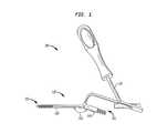
- FIG. 1is a perspective view of a fixation system according to a preferred embodiment of the invention.
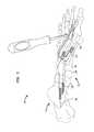
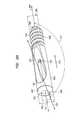
- FIG. 2is a perspective view of a proximal screw member used in the fixation system shown in FIG. 1 according to the preferred embodiment of the invention.
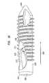
- FIG. 3Ais a perspective view of a distal member used in the fixation system shown in FIG. 1 according to the preferred embodiment of the invention.
- FIG. 3Bis a perspective cross-sectional view of the distal member shown in FIG. 3A according to the preferred embodiment of the invention.
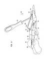
- FIG. 4is a perspective view of the instrument member used in the fixation system shown in FIG. 1 according to the preferred embodiment of the invention.
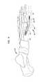
- FIG. 5is a perspective view of the assembled intramedullary fixation assembly inserted into the bones of a patient's foot according to the preferred embodiment of the invention.
- FIG. 6is a side view of the assembled intramedullary fixation assembly shown in FIG. 5 according to the preferred embodiment of the invention.
- FIG. 7is a flow chart illustrating the method of coupling the intramedullary fixation assembly shown in FIGS. 1-6 to tarsal and metatarsal bones in a patient's foot according to the preferred embodiment of the invention.
- FIG. 8is a perspective view of an assembled intramedullary fixation assembly inserted into the metatarsal and trapezoidal bones of a patient's foot according to an alternate embodiment of the invention.
- FIG. 9is a perspective cross-sectional view of the intramedullary fixation assembly according to the alternate embodiment of the invention.
- FIG. 10Ais a perspective view of a metatarsal implant member used in the intramedullary fixation assembly shown in FIG. 8 according to the alternate embodiment of the invention.
- FIG. 10Bis a perspective cross-sectional view of the metatarsal implant member used in the intramedullary fixation assembly shown in FIG. 10A according to the alternate embodiment of the invention.
- FIG. 11is a perspective cross-sectional view of a phalangeal implant member used in the intramedullary fixation assembly shown in FIG. 8 according to the alternate embodiment of the invention.
- FIG. 12is a perspective cross-sectional view of a locking set screw used in the intramedullary fixation assembly shown in FIG. 8 according to the alternate embodiment of the invention.
- FIG. 13is a flow chart illustrating the method of coupling the intramedullary fixation assembly shown in FIGS. 8-12 to metatarsal and phalangeal bones in a patient's foot according to the alternate embodiment of the invention.
- FIG. 14is a perspective view of the assembled intramedullary fixation assembly inserted into the bones of a patient's foot according to an alternate embodiment of the invention.
- FIG. 15is a perspective view of the intramedullary fixation assembly shown in FIG. 14 according to the alternate embodiment of the invention.
- FIG. 16is a perspective view of a metatarsal implant member used in the intramedullary fixation assembly shown in FIGS. 14-15 according to the alternate embodiment of the invention.
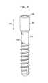
- FIG. 17is a perspective view of a phalangeal implant member used in the intramedullary fixation assembly shown in FIGS. 14-15 according to the alternate embodiment of the invention.
- the fixation system 100includes an intramedullary fixation assembly 110 , comprising a proximal screw member 130 and a distal member 140 .
- Proximal screw member 130is provided on proximal end 135 of assembly 110 and is coupled to a distal member 140 that is provided on the distal end 145 of the fixation assembly 110 .
- proximal screw member 130makes a fixed angle 150 with distal member 140 and this angle 150 determines the angle for arch restoration.
- fixation system 100includes instrument 120 that is utilized to couple intramedullary fixation assembly 110 to the bones in the mid-foot region (not shown).
- intramedullary fixation assembly 110may be made from a Titanium material, although, in other non-limiting embodiments, intramedullary fixation assembly 110 may be made from SST, PEEK, NiTi, Cobalt chrome or other similar types of materials.
- proximal screw member 130is generally cylindrical in shape and extends from first bulbous portion 202 to second tapered end 204 .
- End 204has a diameter that is slightly smaller than diameter 226 of bulbous portion 202 .
- bulbous portion 202has a taper, such as a Morse taper, with a width that decreases from end 211 to end 212 . The taper allows for a locked interference fit with tapered aperture 316 when tapered bulbous portion 202 is combined with tapered aperture 316 , shown and described below.
- bulbous portion 202is generally circular and has a generally hexagonal torque transmitting aperture 208 that traverses length 210 of bulbous portion 202 .
- Torque transmitting aperture 208is utilized to transmit a torque from bulbous portion 202 to tapered end 204 by rotating bulbous portion 202 .
- proximal screw member 130has a first smooth exterior portion 206 extending from end 212 of bulbous portion 202 .
- Portion 206comprises an internal aperture 214 that longitudinally traverses portion 206 in direction 201 .
- Portion 206terminates into a second generally tubular portion 216 .
- Portion 216may comprise internal circular aperture 220 that longitudinally traverses inside portion 216 .
- Internal circular aperture 220is aligned with apertures 214 and 208 along axis 203 to form a continuous opening (i.e., a cannula) from bulbous portion 202 to end 204 .
- the continuous opening or cannulais provided to interact with a guide wire (not shown) by receiving the guide wire within the continuous opening thereby positioning and locating the proximal member 130 .
- the proximal member 130may be provided without apertures 220 and 214 (i.e., the proximal member is solid).
- tubular portion 216has a plurality of circular threads, such as threads 218 , which are circumferentially disposed on the external surface of portion 216 and, with threads 218 having an external diameter 224 .
- Portion 216may also be provided with a self-tapping leading edge 222 to provide portion 216 with the ability to remove bone material during insertion of proximal screw member 130 into bone. It should be appreciated that the length of the proximal member 130 may be selected of varying lengths to allow a surgeon to fuse different joints in a foot (not shown).
- distal member 140 of the preferred embodimentis generally tubular in shape and tapers from a first end 302 to a second end 304 (i.e. end 302 has a diameter 306 that is slightly larger than diameter 308 of end 304 ).
- distal member 140has a constant width from first end 302 to second end 304 .
- first end 302is generally semi-spherical in shape and has an internal circular aperture 316 , which traverses end 302 along direction 301 (i.e. end 302 is generally “donut” shaped).
- circular aperture 316emanates from surface 322 , such that portion 310 has a generally tapered aperture 316 provided in portion 310 .
- Circular aperture 316comprises slope 320 from first end 302 to end 322 of portion 310 . Further, aperture 316 is aligned along axis 303 , which is offset from horizontal axis 305 of distal member 140 . Axis 303 forms an angle 150 with horizontal axis 305 that determines the angle for arch restoration, as shown in FIG. 3A . Angle 150 may be any angle greater than 90 degrees and less than 180 degrees. Tapered aperture 316 when combined with tapered bulbous portion 202 , shown in FIG. 2 , creates a locked interference fit between proximal member 130 and distal member 140 .
- First end 302has a plurality of substantially similar grooves 326 and 328 , which form an “L-shape” with surface 330 of end 302 .
- Grooves 326 and 328are provided to receive instrument 120 of fixation system 100 , which is later described. In other non-limiting embodiments, other similar instruments may be provided to be received within grooves 326 and 328 .
- Distal member 140further comprises a generally smooth portion 310 coupled to end 302 .
- Portion 310has a generally hexagonal shaped aperture 312 , which opens into aperture 316 and which longitudinally traverses through portion 310 in direction 301 .
- a star-shaped aperture, a square-shaped aperture, or any other shaped aperturemay be utilized.
- Circular aperture 316has a diameter 314 that is slightly larger than external diameter 224 of portion 216 and 206 of proximal screw member 130 , with portions 216 and 206 being slidably received within aperture 316 of portion 310 .
- Aperture 316has a diameter that is smaller than diameter 226 of bulbous portion 202 .
- Portion 310 of distal member 140terminates into a second generally cylindrical portion 318 which has a plurality of threads 324 , which are circumferentially disposed on the external surface of portion 318 .
- Portion 318has an internal circular aperture 326 which is longitudinally coextensive with portion 318 in direction 301 .
- Circular aperture 326aligns with aperture 312 to form a continuous opening from end 302 to end 304 .
- instrument 120is illustrated for coupling proximal screw member 130 to distal member 140 .
- instrument 120includes a handle portion 402 coupled to a rod portion 404 .
- Rod portion 404emanates from handle portion 402 at end 406 and terminates into a rectangular planar portion 408 at end 410 .
- Planar portion 408is aligned along axis 401 and is fixably coupled to a generally cylindrical tubular portion 412 (i.e., an aiming device).
- Portion 412traverses portion 408 from top surface 414 to bottom surface 416 .
- tubular portion 412is aligned along dissimilar axis 403 , forming an angle 405 with axis 401 .
- tubular portion 412has a through aperture 420 that longitudinally traverses portion 412 along axis 403 .
- Planar portion 408is coupled to planar portion 422 , with portion 422 having a width slightly smaller than width of portion 408 .
- Portion 422terminates into a generally “U-shaped” portion 424 with portion 424 being orthogonal to portion 422 .
- portion 424has a plurality of substantially similar sides 426 and 428 which are provided to be slidably coupled to grooves 326 and 328 of distal member 140 .
- sides 426 and 428 of instrument 120are received in respective grooves 326 and 328 of distal member 140 , of FIGS. 3A-3B , thereby slidably coupling distal member 140 to instrument 120 .
- axis 303 of aperture 316is aligned along substantially the same axis as axis 403 of instrument 120 .
- Proximal screw member 130is coupled to distal member 140 by slidably coupling portions 206 and 216 through aperture 420 of tubular portion 412 .
- Tubular portion 412guides proximal screw member 130 through internal aperture 420 and into aperture 316 on surface 322 and may also guide a Kirschner wire (K wire) or a drill.
- K wireKirschner wire
- Aperture 316being tapered along axis 303 , causes proximal screw member 130 to form an angle 150 with distal member 140 , with proximal member 130 being aligned along an axis 303 , which is substantially the same axis as axis 403 of tubular portion 412 of instrument 120 .
- the fixation system 100utilizes the intramedullary fixation assembly 110 for treating and fixating the deteriorated and damaged or fractured bones in the human foot 500 .
- the intramedullary assembly 110is coupled to the medullary canals of the first metatarsal 502 , medial cuneiform 504 , navicular 506 and talus bone 508 .
- Talus bone 508makes up part of the ankle joint where the threaded portion 216 of the proximal screw member 130 of the intramedullary assembly 110 is threadably coupled.
- the medial cuneiform 504 and navicular 506 bonesare most affected by Diabetic Charcot foot disorder that causes deterioration and collapse of the arch of the foot 500 .
- the intramedullary assembly 110may be used within each of the five rays, with a ray representing a line drawn from each metatarsal bone to the talus. The angulation in the smaller rays will be smaller than the two rays (i.e., a line from the first and second metatarsal bones to the talus bone).
- the diameter of distal member 140will decrease from the large ray to the small ray.
- the angulationmay be any angle greater than 90 degrees and less than 180 degrees.
- the angle for the first raymay be 150-170 degrees and the angles for the other rays may be 160-175 degrees.
- the intramedullary fixation assembly 110may be utilized to reconstruct an arch in a mid-foot region of a human foot 500 .
- the methodstarts in step 700 and proceeds to step 702 , whereby a Dorsal Lis Franc incision (i.e., mid-foot incision) (not shown) is made in foot 500 in order to gain access to the joint.
- the joint capsuleis separated by “Gunstocking” foot 500 in direction 601 (i.e., the foot 500 is bent mid-foot) to expose the articular surface 602 and the articulating cartilage is removed.
- the intramedullary canalis reamed and the distal member 140 is inserted into the intramedullary canal (not shown) of the metatarsal 502 .
- the distal member 140may be inserted by impaction, by press fit, by reaming a hole in the intramedullary canal (not shown) or substantially any other similar strategy or technique.
- step 708the instrument 120 is coupled to the distal member 140 by coupling sides 426 and 428 of instrument 120 to respective grooves 326 and 328 .
- step 710initial positioning of the proximal member 130 is assessed with the use of a guide wire through portion 412 (i.e., aiming device).
- a countersink drillis inserted through portion 412 and the proximal cortex is penetrated.
- a cannulated drill or guide wireis used to pre-drill the hole through the joints selected for fusion.
- step 714the proximal screw member 130 is inserted over the guide wire and into the distal member 140 .
- proximal member 130is inserted through tubular portion 412 (i.e., aiming device), causing proximal member 130 to travel through internal longitudinal aperture 420 , into distal member 140 and further into bones 504 , 506 and 508 until rigid connection with the tapered aperture 316 is made, thereby compressing the joint.
- a locking elementsuch as a plate or a washer is coupled to end 302 of the intramedullary fixation assembly 110 to further secure proximal threaded member 130 to distal member 140 .
- step 716the instrument 120 is removed and the dorsal Lis Franc (i.e., mid-foot) incision is closed. The method ends in step 718 .
- intramedullary fixation assembly 110may be inserted into any of the bones of a foot 500 such as, but not limited to the metatarsal, cuneiform, calcaneus, cuboid, talus and navicular bones, in order to restore the natural anatomical shape of the arch of the foot 500 .
- the fixation system 100in one non-limiting embodiment, is utilized to couple the intramedullary fixation assembly 110 to the foot 500 , which causes the metatarsal 504 , medial cuneiform 504 , navicular 506 and talus 508 bones to be aligned to the proper anatomical shape of an arch when assembled within foot 500 .
- the intramedullary fixation assembly 110is delivered through a dorsal midfoot incision, thereby reducing the disruption to the plantar tissues and/or the metatarsal heads while at the same time minimizing the tension on the skin. This allows for improved wound closure, reduced operating room time, reduction in the number of incisions required and reduction in the total length of incisions.
- the intramedullary assembly 110may be utilized with graft material (i.e., autograft, allograft or other biologic agent).
- an intramedullary fixation assembly 800may comprise three interconnected members for the internal fixation of the first metatarsal 845 to the first proximal phalange 850 in the human foot 840 or any other appropriate use for the internal fixation of the other bones in the human foot 840 .
- the interconnected members of the intramedullary fixation assembly 800may be inserted into the medullary canals of the first metatarsal 845 and the first proximal phalange 850 in order to restore the angle in the toes of a human foot 840 .
- the intramedullary fixation assembly 800may comprise a metatarsal implant member 810 , a phalangeal implant member 820 and an optional locking set screw 830 .
- the intramedullary fixation assembly 800comprises the metatarsal implant member 810 , which is provided on the distal end 935 of the intramedullary fixation assembly 800 , the phalangeal implant member 820 provided on the proximal end 940 and the optional locking set screw 830 provided to threadably couple to the metatarsal implant member 810 , thereby pressure coupling the metatarsal implant member 810 to the phalangeal implant member 820 .
- Optional locking set screw 830thereby locks the metatarsal implant member 810 to the phalangeal implant member 820 and allows for incremental adjustment of the position of phalangeal implant member 820 within the metatarsal implant member 810 as will be shown and described.
- intramedullary fixation assembly 800may be made from a Titanium material, although, in other non-limiting embodiments, intramedullary fixation assembly 800 may be made from SST, PEEK, NiTi, Cobalt chrome or other similar types of materials.
- metatarsal implant member 810 of the embodimentis generally tubular in shape and tapers from a first end 1002 to a second end 1004 (i.e. end 1002 has a diameter 1006 that is slightly larger than diameter 1008 of end 1004 ).
- metatarsal implant member 810has a constant width from first end 1002 to second end 1004 .
- first end 1002is generally semi-spherical in shape and has an internal circular aperture 1016 , which traverses end 1002 along direction 1001 (i.e. end 1002 is generally “donut” shaped).
- circular aperture 1016is aligned along axis 1003 , which is offset from horizontal axis 1005 at an angle 1050 .
- Angle 1050causes circular aperture 1016 to emanate from surface 1022 , such that circular aperture 1016 on cylindrical portion 1010 is generally tapered with the diameter 1030 being slightly smaller than diameter 1032 .
- angle 1050initially determines the angle for restoration, as shown in FIG. 10A .
- Angle 1050may be any angle greater than 90 degrees and less than 180 degrees.
- Circular aperture 1016also includes a plurality of substantially similar threads 1028 that are provided on interior surface 1026 of metatarsal implant member 810 . The plurality of substantially similar threads 1028 when combined with head portion 1105 of phalangeal implant member 820 , shown in FIG. 11 , creates a locked interference fit between metatarsal implant member 810 and phalangeal implant member 820 .
- Circular aperture 1016has a diameter 1014 that is provided to receive head portion 1105 of phalangeal implant member 820 , which will be shown in FIG. 11 .
- metatarsal implant member 810further comprises a generally smooth portion 1010 coupled to end 1002 .
- Portion 1010has a generally hexagonal shaped aperture 1012 aligned along axis 1005 .
- Aperture 1012emanates from circular aperture 1016 , traverses through portion 1010 in direction 1001 and terminates into a generally cylindrical portion 1018 .
- aperture 1012is longitudinally coextensive with portion 1018 in direction 1001 and emanates from second end 1004 . In this manner, a continuous opening from end 1002 to end 1004 may be formed to receive a Kirschner wire (K wire) or a drill.
- K wireKirschner wire
- portion 1018has a plurality of substantially similar circumferential threads, such as threads 1024 , which are circumferentially disposed on the external surface of portion 1018 .
- plurality of circumferential threads, such as threads 1024are provided so that rotating metatarsal implant member 810 causes the plurality of circumferential threads 1024 to grip or catch the medullary canal of first metatarsal 845 (shown in FIG. 8 ) causing metatarsal implant member 810 to travel into the first metatarsal 845 .
- metatarsal implant member 810may be utilized in any metatarsal for restoration of the angle in the human foot.
- the metatarsal implant membermay be utilized for fusion of other joints in the human body.
- phalangeal implant member 820is generally cylindrical in shape, has a generally solid body and extends from a spherical head portion 1105 to tapered end 1104 .
- Spherical head portion 1105is generally spherical in shape and has a generally hexagonal torque transmitting aperture 1108 traversing length 1110 of head portion 1105 .
- Torque transmitting aperture 1108is utilized to transmit a torque from head portion 1105 to tapered end 1104 when head portion 1105 is rotated.
- the largest diameter 1126 of head portion 1105is slightly larger than diameter 1032 of circular aperture 1016 on metatarsal implant member 810 , which was shown previously in FIGS. 10A-B .
- Head portion 1105further has a plurality of generally flat edges 1111 (i.e., head portion 1105 has a plurality of step-like protrusions) which are provided to engage circular aperture 1016 .
- the flat edges 1111allow for the phalangeal implant member 820 to be coupled at a plurality of angles to metatarsal implant member 810 .
- Each of the plurality of edges 1111allows for a unique angle in a locked interference fit to be created by head portion 1105 within circular aperture 1016 , shown in FIGS. 10A-B , as head portion 1105 of phalangeal implant member 820 is positioned within circular aperture 1016 of metatarsal implant member 810 , which will be shown and described below
- phalangeal implant member 820has a first smooth exterior portion 1106 extending from head portion 1105 .
- Portion 1106is generally cylindrical and terminates into a second generally cylindrical portion 1116 , with exterior portion 1106 and cylindrical 1116 having a uniform diameter.
- cylindrical portion 1116has a plurality of circular threads, such as threads 1118 , which are circumferentially disposed on the external surface of portion 1116 .
- Cylindrical portion 1116may also be provided with a self-tapping leading edge 1122 to provide portion 1116 with the ability to remove bone material during insertion of the phalangeal implant member 820 into bone or other matter.
- the length of the phalangeal implant member 820may be selected of varying lengths to allow a surgeon to fuse different joints (not shown).
- the phalangeal implant member 820may have a continuous opening (i.e., a cannula) from torque transmitting aperture 1108 to tapered end 1104 .
- the continuous opening or cannulamay be provided to interact with a guide wire (not shown), such as a Kirschner wire, by receiving the guide wire within the continuous opening thereby positioning and locating the phalangeal implant 820 .
- intramedullary fixation assembly 800may comprise an optional locking set screw 830 to couple the metatarsal implant member 810 to the phalangeal implant member 820 .
- Locking set screw 830is generally tubular in shape and extends from open first end 1202 to an open second end 1204 .
- First end 1202has a generally flat surface while second end 1204 has a semi-spherical groove 1206 .
- the semi-spherical groove 1206is provided to receive head portion 1105 of the phalangeal implant member 820 in an assembled intramedullary fixation assembly 800 .
- locking set screw 830has a generally hexagonal torque-transmitting aperture 1208 that traverses from first end 1202 to second end 1204 .
- a star-shaped aperture, a square-shaped aperture, or any other shaped aperture of any lengthmay be utilized without departing from the scope of the invention.
- Torque transmitting aperture 1208is utilized to receive a torque shaped tool in order to rotate and couple locking set screw 830 to first metatarsal implant member 810 (not shown).
- Locking set screw 830is also provided with a plurality of substantially similar circumferential threads 1210 in order to engage the plurality of threads 1028 on the interior surface 1026 of the metatarsal implant member 810 (shown in FIGS. 10A and 10B ) and threadably couple (i.e., mechanically couple) the locking set screw 830 to the metatarsal implant member 810 , thereby preventing the phalangeal implant member 820 from backing out of circular aperture 1016 on metatarsal implant member 810 and losing compression.
- the intramedullary fixation assembly 800may be utilized to reconstruct an arch and/or angle in a metatarsal phalangeal joint of a human foot 840 .
- the methodstarts in step 1300 and proceeds to step 1302 , whereby a dorsal incision is made in the metatarsal phalangeal (MTP) joint 855 of foot 840 in order to gain access to the MTP joint 855 .
- the joint capsuleis separated by “Gunstocking” foot 840 (i.e., the foot 840 is bent at MTP joint 855 ) to expose the articular surfaces of the metatarsal 845 and first proximal phalange 850 .
- the articulating cartilageis removed by denuding the cartilage in the MTP joint 855 .
- the intramedullary canal of the metatarsal 845is reamed by drilling the metatarsal intramedullary canal and the metatarsal implant member 810 is inserted.
- the cylindrical portion 1018 of the metatarsal implant member 810is inserted first into the intramedullary canal (of the metatarsal 845 to a predetermined depth until end 1002 is oriented at the opening of the MTP joint 855 .
- the metatarsal implant member 810may be inserted by impaction, by press fit, by reaming a hole in the intramedullary canal (not shown) or any other similar strategy or technique.
- step 1308the dorsal metatarsal cortex (not shown) is drilled and reamed to allow access to metatarsal implant member 810 from an anterior grade access.
- a cannulated drill or guide wireis used to pre-drill a pilot hole through the articular surface of the phalange 850 .
- the phalangeal implant member 820is inserted into the metatarsal implant member 810 and into the pre-drilled pilot hole by inserting the tapered end 1104 (shown in FIG. 11 ) into the circular aperture 1016 (shown in FIG. 10A-B ) at surface 1022 and until the tapered end 1104 emanates from circular aperture 1016 .
- the phalangeal implant member 820is inserted into the phalange 850 (shown in FIG. 8 ).
- step 1314the phalangeal implant member 820 is aligned and angle 845 (shown in FIG. 9 ) is formed and compression is applied to the intramedullary fixation assembly 800 by rotating the phalangeal implant member 820 .
- the phalangeal implant member 820is fixed at angle 845 (shown in FIG. 9 ).
- the locking set screw 830is inserted into metatarsal implant member 810 to lock angle 845 (shown in FIG. 9 ) in place.
- step 1318the dorsal incision is closed. The method ends in step 1320 .
- intramedullary fixation assembly 1400is provided so that metatarsal implant member 1410 resides at a constant and fixed angle 1425 with phalangeal implant member 1420 .
- the fixed angle 1425may vary between 15 and 30 degrees and may be selected by, in one example, a surgeon to provide for the internal fixation of the bones in the human foot.
- the metatarsal implant member 1410shown in FIG. 16 , is substantially similar to the distal member 140 shown and described in a previous embodiment in FIGS. 3A and 3B , and is generally tubular in shape and tapers from a first end 1602 to a second end 1604 (i.e. end 1602 has a diameter that is slightly larger than diameter of end 1604 ).
- metatarsal implant member 1410has a constant width from first end 1602 to second end 1604 .
- first end 1602has an internal circular aperture 1606 partially traversing metatarsal implant member 1410 along direction 301 .
- metatarsal implant member 1410has a longitudinal aperture 1612 emanating from surface 1610 , such that aperture 1612 forms a slope 1614 from in portion 1620 .
- Slope 1614determines the angle for restoration of the bones in a foot when phalangeal implant member 1420 (not shown) is coupled to metatarsal implant member 1410 and locks the phalangeal implant member at the fixed angle.
- phalangeal implant member 1420shown in FIG. 17 , is substantially similar to the proximal screw member 130 that was shown in a previous embodiment, however, phalangeal implant member 1420 includes bulbous portion 1430 having a constant diameter.
- bulbous portion 1430may include a morse taper (i.e., the diameter decreases from end 1440 in direction 1445 )
- the bulbous portion 1430is provided to be received inside aperture 1606 so that phalangeal implant member 1420 resides at a fixed angle with respect to metatarsal implant member 1410 .
- intramedullary fixation assembly 800may be inserted into any of the metatarsal and phalangeal bones of a foot 840 in order to restore the natural anatomical shape of the foot 840 .
- the intramedullary fixation assembly 800is delivered through a dorsal incision, thereby reducing the disruption to the plantar tissues and/or the metatarsal heads while at the same time minimizing the tension on the skin. This allows for improved wound closure, reduced operating room time, reduction in the number of incisions required and reduction in the total length of incisions.
- the intramedullary fixation assembly 800may also be utilized to restore any of the other bones in the human body. It should also be appreciated that in other non-limiting embodiments, the intramedullary assembly 800 may be utilized with graft material (i.e., autograft, allograft or other biologic agent).
- graft materiali.e., autograft, allograft or other biologic agent
Landscapes
- Health & Medical Sciences (AREA)
- Orthopedic Medicine & Surgery (AREA)
- Surgery (AREA)
- Life Sciences & Earth Sciences (AREA)
- Heart & Thoracic Surgery (AREA)
- Veterinary Medicine (AREA)
- Engineering & Computer Science (AREA)
- Biomedical Technology (AREA)
- Nuclear Medicine, Radiotherapy & Molecular Imaging (AREA)
- Medical Informatics (AREA)
- Molecular Biology (AREA)
- Animal Behavior & Ethology (AREA)
- General Health & Medical Sciences (AREA)
- Public Health (AREA)
- Neurology (AREA)
- Dentistry (AREA)
- Oral & Maxillofacial Surgery (AREA)
- Surgical Instruments (AREA)
- Prostheses (AREA)
Abstract
Description
This application is a division of U.S. application Ser. No. 12/460,069, filed Jul. 13, 2009, which is a continuation-in-part application of Non-Provisional application Ser. No. 12/456,808, filed Jun. 23, 2009, which claims the benefit of Provisional Application Ser. No. 61/132,932, filed Jun. 24, 2008, the entire contents of the entire chain of applications hereby being incorporated by reference.
This invention relates to the field of orthopedic implant devices, and more particularly, to an intramedullary fixation assembly used for fusion of the angled joints, bones and deformity correction, such as the metatarsal and phalangeal bones in the foot.
Orthopedic implant devices, such as intramedullary nails, plates, rods and screws are often used to repair or reconstruct bones and joints affected by trauma, degeneration, deformity and disease, such as Charcot arthropathy caused by diabetes in some patients, Hallux Valgus deformities, failed Keller Bunionectomies, Rheumatoid Arthritis, and severe deformities. Charcot arthropathy (or Charcot foot) is a destructive process affecting many regions including joints of the foot and ankle in diabetics. This condition causes bony fragmentation, dislocation, and fractures that eventually progresses to foot deformity, bony prominences, ulceration and instability of the foot. Charcot arthropathy can affect any joint in the body but is often seen in the feet affecting the metatarsal, tarsometatarsal and tarsal joints and frequently causes the foot to lose its arch or curvature, thus resulting in “flat footedness” in the mid-foot region.
Early treatment for Charcot foot includes the use of therapeutic footwear, immobilization of the foot and/or non-weight bearing treatment. Surgical treatments include orthopedic fixation devices that fixate the bones in order to fuse them into a stable mass. These orthopedic implant devices realign bone segments and hold them together in compression until healing occurs, resulting in a stable mass.
In order to restore an arch in a Charcot foot, the physician must estimate the arch and manually align the bones and deliver the screws to hold the bones in place, while reducing bone purchase. Intramedullary nails and/or a plate with a lag screw too have deficiencies. These intramedullary nails also do not reconstruct an arch that is lost due to Charcot foot disease.
Moreover, infections and wound complications are a major concern in the aforementioned procedures. Wound closure is technically demanding for the surgeon, and devices that add surface prominence, such as plates or exposed screws, add to the difficulty by requiring greater tissue tension during incision reapproximation. This increases the risk of postoperative wound infections and dehiscence that may ultimately result in limb amputation.
Various implants have been utilized for surgical treatment of these bones and joints, including bone screws. Implants have also been utilized to treat severe deformities in the metatarsal and phalangeal bones, including multiple screws and plates. These multiple screws and plate implants have been commonly used in a first metatarsal-phalangeal fusion procedure to fuse the first metatarsal to the first phalangeal bone in hallux valgus deformities, failed keller bunionectomies, rheumatoid arthritis, and other types of severe deformities in the metatarsal and phalange bones. While these devices allow fixation and promote fusion, they do not deliver restoration of the arch in a Charcot foot nor are they effective in metatarsal-phalangeal (MTP) fusion procedures.
Particularly, screw implants in MTP procedures are ineffective in delivering sufficient compression to the bones in the foot, preventing screw head break out, or delivering effective bending resistance. Moreover, hard to control dorsiflexion and valgus angles as well skin irritation from proximity to the skin prevents these screw implants from being readily utilized for surgical treatment. Yet further, plate implants used with bone screws too have the same drawbacks as fixed varus and valgus angles, lack of direct compression across the MTP joint, and skin irritations from proximity to the skin reduce the effectiveness of these implants.
There is therefore a need for an intramedullary fixation assembly and method of use that overcomes some or all of the previously delineated drawbacks of prior fixation assemblies.
An object of the invention is to overcome the drawbacks of previous inventions.
Another object of the invention is to provide a novel and useful intramedullary fixation assembly that may be utilized to treat bones in a mid-foot and forefoot regions.
Another object of the invention is to restore the arch by utilizing an intramedullary assembly.
Another object of the invention is to provide a system for treating deteriorating bones in a mid-foot region.
Another object of the invention is to provide a method for restoring the arch of the foot by delivering a fixator that can be coupled in a patient's foot.
Another object of the invention is to fuse the metatarsal phalangeal joint by utilizing an intramedullary assembly.
In a first non-limiting aspect of the invention, a fixation assembly comprising two members is provided. A first member, positioned at a proximal end of the fixation assembly, has an elongated portion and a tapered bulbous end. A second member, positioned at a distal end of the fixation assembly, has an internal tapered aperture, wherein the elongated portion resides within the internal tapered aperture. The first member forms a fixed angle with the second member, thereby selectively coupling the first member to the second member.
In a second non-limiting aspect of the invention, a method for reconstructing an arch in a mid-foot region comprises eight steps. Step one includes making an incision in the mid-foot region of a patient's foot. Step two includes gunstocking the foot to expose the articular surface. Step three includes reaming the intramedullary canal and inserting a distal member. Step four includes coupling the instrument to the distal member. Step five includes assessing the position of the proximal member with a guide wire. Step six includes pre-drilling a hole through the joints selected for fusion. The seventh step includes inserting the proximal member over the guide wire until rigid connection with the tapered aperture is made that compresses the joint and wherein the proximal member is at an angle to the distal member. The eighth step includes removing the instrument and closing the incision, thereby causing the arch to be formed in the mid-foot region.
In a third non-limiting aspect of the invention, an instrument is combined with a fixation assembly for reconstructing an arch in a mid-foot region. The instrument has a handle, a “U-shaped” recess having two sides and a tapered bore. The intramedullary fixation assembly has a first member and a second member. The first member is positioned at a proximal end of the intramedullary fixation assembly. The first member has an elongated portion and a bulbous portion. The second member is positioned at a distal end of the intramedullary fixation assembly. The second member has an internal tapered aperture, a plurality of grooves and a threaded portion. The elongated portion resides within the internal tapered aperture, and a “U-shaped” recess having two sides that couple the first member to the second member, and further coupling the instrument to the intramedullary fixation assembly for reconstructing the arch in the mid-foot region.
In a fourth non-limiting aspect of the invention, an intramedullary fixation assembly for bone fusion includes a first member positioned at a proximal end of the intramedullary fixation assembly, and a second member positioned at a distal end of the intramedullary fixation assembly. The first member is slideably coupled to the second member and provides for an interference fit with the second member.
In a fifth non-limiting aspect of the invention, a method for fusing a metatarsal phalangeal joint comprises seven steps. Step one includes providing a fixation assembly, where the fixation assembly includes a metatarsal implant member for connecting to a metatarsal bone and a phalangeal implant member for connecting to a phalange bone. Step two includes drilling the metatarsal medullary canal and drilling the phalangeal medullary canal. Step three includes inserting the metatarsal implant member into the metatarsal medullary canal. Step four includes inserting the phalangeal implant member into the internal aperture of the metatarsal implant member. Step six includes inserting the phalangeal implant member into the phalangeal medullary canal. Step seven includes applying compression to the phalangeal implant member to lock the metatarsal implant member to the phalangeal implant member, thereby fusing the metatarsal phalangeal joint.
In a sixth non-limiting aspect of the invention, a fixation assembly for a metatarsal-phalangeal fusion in a human foot includes a metatarsal implant member for connecting to a metatarsal bone, where the metatarsal implant member is positioned at a proximal end of the fixation assembly, and a phalangeal implant member for connecting to a phalange bone, where the phalangeal implant member is positioned at a distal end of the fixation assembly. The phalangeal implant member is slideably coupled to the metatarsal implant member and provides for an interference fit with the metatarsal implant member.
A further understanding of the invention can be obtained by reference to a preferred embodiment set forth in the illustrations of the accompanying drawings. Although the illustrated embodiment is merely exemplary of systems and methods for carrying out the invention, both the organization and method of operation of the invention, in general, together with further objectives and advantages thereof, may be more easily understood by reference to the drawings and the following description. The drawings are not intended to limit the scope of this invention, which is set forth with particularity in the claims as appended or as subsequently amended, but merely to clarify and exemplify the invention.
For a more complete understanding of the invention, reference is now made to the following drawings in which:
The invention may be understood more readily by reference to the following detailed description of preferred embodiment of the invention. However, techniques, systems and operating structures in accordance with the invention may be embodied in a wide variety of forms and modes, some of which may be quite different from those in the disclosed embodiment. Consequently, the specific structural and functional details disclosed herein are merely representative, yet in that regard, they are deemed to afford the best embodiment for purposes of disclosure and to provide a basis for the claims herein, which define the scope of the invention. It must be noted that, as used in the specification and the appended claims, the singular forms “a”, “an”, and “the” include plural referents unless the context clearly indicates otherwise.
Referring now toFIG. 1 , there is shown afixation system 100 which is made in accordance with the teachings of the preferred embodiment of the invention. As shown, thefixation system 100 includes anintramedullary fixation assembly 110, comprising aproximal screw member 130 and adistal member 140.Proximal screw member 130 is provided onproximal end 135 ofassembly 110 and is coupled to adistal member 140 that is provided on thedistal end 145 of thefixation assembly 110. Also,proximal screw member 130 makes afixed angle 150 withdistal member 140 and thisangle 150 determines the angle for arch restoration. Moreover,fixation system 100 includesinstrument 120 that is utilized to coupleintramedullary fixation assembly 110 to the bones in the mid-foot region (not shown). It should be appreciated that in one non-limiting embodiment,intramedullary fixation assembly 110 may be made from a Titanium material, although, in other non-limiting embodiments,intramedullary fixation assembly 110 may be made from SST, PEEK, NiTi, Cobalt chrome or other similar types of materials.
As shown inFIG. 2 ,proximal screw member 130 is generally cylindrical in shape and extends from firstbulbous portion 202 to secondtapered end 204.End 204 has a diameter that is slightly smaller thandiameter 226 ofbulbous portion 202. Additionally,bulbous portion 202 has a taper, such as a Morse taper, with a width that decreases fromend 211 to end212. The taper allows for a locked interference fit with taperedaperture 316 when taperedbulbous portion 202 is combined with taperedaperture 316, shown and described below. Moreover,bulbous portion 202 is generally circular and has a generally hexagonaltorque transmitting aperture 208 that traverseslength 210 ofbulbous portion 202. However, a star-shaped aperture, a square-shaped aperture, or any other shaped aperture may be utilized without departing from the scope of the invention.Torque transmitting aperture 208 is utilized to transmit a torque frombulbous portion 202 totapered end 204 by rotatingbulbous portion 202.
Further,proximal screw member 130 has a firstsmooth exterior portion 206 extending fromend 212 ofbulbous portion 202.Portion 206 comprises aninternal aperture 214 that longitudinally traversesportion 206 in direction201.Portion 206 terminates into a second generallytubular portion 216.Portion 216 may comprise internalcircular aperture 220 that longitudinally traverses insideportion 216. Internalcircular aperture 220 is aligned withapertures axis 203 to form a continuous opening (i.e., a cannula) frombulbous portion 202 to end204. The continuous opening or cannula is provided to interact with a guide wire (not shown) by receiving the guide wire within the continuous opening thereby positioning and locating theproximal member 130. In other non-limiting embodiments, theproximal member 130 may be provided withoutapertures 220 and214 (i.e., the proximal member is solid).
Furthermore,tubular portion 216 has a plurality of circular threads, such asthreads 218, which are circumferentially disposed on the external surface ofportion 216 and, withthreads 218 having anexternal diameter 224.Portion 216 may also be provided with a self-tappingleading edge 222 to provideportion 216 with the ability to remove bone material during insertion ofproximal screw member 130 into bone. It should be appreciated that the length of theproximal member 130 may be selected of varying lengths to allow a surgeon to fuse different joints in a foot (not shown).
As shown inFIGS. 3A-3B ,distal member 140 of the preferred embodiment is generally tubular in shape and tapers from afirst end 302 to a second end304 (i.e.end 302 has adiameter 306 that is slightly larger thandiameter 308 of end304). However, in another non-limiting embodiment,distal member 140 has a constant width fromfirst end 302 tosecond end 304. Further,first end 302 is generally semi-spherical in shape and has an internalcircular aperture 316, which traversesend 302 along direction301 (i.e.end 302 is generally “donut” shaped). Additionally,circular aperture 316 emanates fromsurface 322, such thatportion 310 has a generally taperedaperture 316 provided inportion 310.Circular aperture 316 comprisesslope 320 fromfirst end 302 to end322 ofportion 310. Further,aperture 316 is aligned alongaxis 303, which is offset fromhorizontal axis 305 ofdistal member 140.Axis 303 forms anangle 150 withhorizontal axis 305 that determines the angle for arch restoration, as shown inFIG. 3A .Angle 150 may be any angle greater than 90 degrees and less than 180 degrees.Tapered aperture 316 when combined with taperedbulbous portion 202, shown inFIG. 2 , creates a locked interference fit betweenproximal member 130 anddistal member 140.First end 302 has a plurality of substantiallysimilar grooves surface 330 ofend 302.Grooves instrument 120 offixation system 100, which is later described. In other non-limiting embodiments, other similar instruments may be provided to be received withingrooves
As shown inFIG. 4 ,instrument 120 is illustrated for couplingproximal screw member 130 todistal member 140. Particularly,instrument 120 includes ahandle portion 402 coupled to arod portion 404.Rod portion 404 emanates fromhandle portion 402 atend 406 and terminates into a rectangularplanar portion 408 atend 410.Planar portion 408 is aligned alongaxis 401 and is fixably coupled to a generally cylindrical tubular portion412 (i.e., an aiming device).Portion 412 traversesportion 408 fromtop surface 414 tobottom surface 416. Further,tubular portion 412 is aligned alongdissimilar axis 403, forming anangle 405 withaxis 401. Also,tubular portion 412 has a throughaperture 420 that longitudinally traversesportion 412 alongaxis 403.
In operation, sides426 and428 ofinstrument 120 are received inrespective grooves distal member 140, ofFIGS. 3A-3B , thereby slidably couplingdistal member 140 toinstrument 120. In this position,axis 303 ofaperture 316 is aligned along substantially the same axis asaxis 403 ofinstrument 120.Proximal screw member 130 is coupled todistal member 140 byslidably coupling portions aperture 420 oftubular portion 412.Tubular portion 412 guidesproximal screw member 130 throughinternal aperture 420 and intoaperture 316 onsurface 322 and may also guide a Kirschner wire (K wire) or a drill.Proximal screw member 130, ofFIG. 2 , travels into bone asportions aperture 316 atend 302 untilbulbous portion 202 is restrained bysurface 322 and end302.Aperture 316, being tapered alongaxis 303, causesproximal screw member 130 to form anangle 150 withdistal member 140, withproximal member 130 being aligned along anaxis 303, which is substantially the same axis asaxis 403 oftubular portion 412 ofinstrument 120.
In operation, and as best shown inFIGS. 5 ,6 and7, thefixation system 100 utilizes theintramedullary fixation assembly 110 for treating and fixating the deteriorated and damaged or fractured bones in thehuman foot 500. This restores the arch in ahuman foot 500 by coupling theintramedullary fixation assembly 110 to thehuman foot 500 of a left leg. In one-non limiting example, and as shown inFIG. 5 , theintramedullary assembly 110 is coupled to the medullary canals of thefirst metatarsal 502,medial cuneiform 504,navicular 506 andtalus bone 508.Talus bone 508 makes up part of the ankle joint where the threadedportion 216 of theproximal screw member 130 of theintramedullary assembly 110 is threadably coupled. Themedial cuneiform 504 andnavicular 506 bones are most affected by Diabetic Charcot foot disorder that causes deterioration and collapse of the arch of thefoot 500. It should be appreciated that theintramedullary assembly 110 may be used within each of the five rays, with a ray representing a line drawn from each metatarsal bone to the talus. The angulation in the smaller rays will be smaller than the two rays (i.e., a line from the first and second metatarsal bones to the talus bone). Also, the diameter ofdistal member 140 will decrease from the large ray to the small ray. In one non-limiting example, the angulation may be any angle greater than 90 degrees and less than 180 degrees. For example, the angle for the first ray may be 150-170 degrees and the angles for the other rays may be 160-175 degrees.
As shown inFIGS. 6 and 7 , theintramedullary fixation assembly 110 may be utilized to reconstruct an arch in a mid-foot region of ahuman foot 500. As shown, the method starts instep 700 and proceeds to step702, whereby a Dorsal Lis Franc incision (i.e., mid-foot incision) (not shown) is made infoot 500 in order to gain access to the joint. Instep 704, the joint capsule is separated by “Gunstocking”foot 500 in direction601 (i.e., thefoot 500 is bent mid-foot) to expose thearticular surface 602 and the articulating cartilage is removed. Next, instep 706, the intramedullary canal is reamed and thedistal member 140 is inserted into the intramedullary canal (not shown) of themetatarsal 502. In other non-limiting embodiments, thedistal member 140 may be inserted by impaction, by press fit, by reaming a hole in the intramedullary canal (not shown) or substantially any other similar strategy or technique.
Next, instep 708, theinstrument 120 is coupled to thedistal member 140 by couplingsides instrument 120 torespective grooves step 710, initial positioning of theproximal member 130 is assessed with the use of a guide wire through portion412 (i.e., aiming device). Next, instep 712, a countersink drill is inserted throughportion 412 and the proximal cortex is penetrated. In this step, a cannulated drill or guide wire is used to pre-drill the hole through the joints selected for fusion. Instep 714, theproximal screw member 130 is inserted over the guide wire and into thedistal member 140. Particularly, theproximal member 130 is inserted through tubular portion412 (i.e., aiming device), causingproximal member 130 to travel through internallongitudinal aperture 420, intodistal member 140 and further intobones aperture 316 is made, thereby compressing the joint. In one non-limiting embodiment, a locking element (not shown) such as a plate or a washer is coupled to end302 of theintramedullary fixation assembly 110 to further secure proximal threadedmember 130 todistal member 140. Next, instep 716 theinstrument 120 is removed and the dorsal Lis Franc (i.e., mid-foot) incision is closed. The method ends instep 718.
It should be appreciated that a plurality of intramedullary fixation assemblies, such asintramedullary fixation assembly 110, may be inserted into any of the bones of afoot 500 such as, but not limited to the metatarsal, cuneiform, calcaneus, cuboid, talus and navicular bones, in order to restore the natural anatomical shape of the arch of thefoot 500. Thus, thefixation system 100, in one non-limiting embodiment, is utilized to couple theintramedullary fixation assembly 110 to thefoot 500, which causes themetatarsal 504,medial cuneiform 504,navicular 506 andtalus 508 bones to be aligned to the proper anatomical shape of an arch when assembled withinfoot 500. It should be appreciated that theintramedullary fixation assembly 110 is delivered through a dorsal midfoot incision, thereby reducing the disruption to the plantar tissues and/or the metatarsal heads while at the same time minimizing the tension on the skin. This allows for improved wound closure, reduced operating room time, reduction in the number of incisions required and reduction in the total length of incisions. It should also be appreciated that in other non-limiting embodiments, theintramedullary assembly 110 may be utilized with graft material (i.e., autograft, allograft or other biologic agent).
In an alternate embodiment, as shown inFIG. 8 , anintramedullary fixation assembly 800 may comprise three interconnected members for the internal fixation of thefirst metatarsal 845 to the firstproximal phalange 850 in thehuman foot 840 or any other appropriate use for the internal fixation of the other bones in thehuman foot 840. The interconnected members of theintramedullary fixation assembly 800 may be inserted into the medullary canals of thefirst metatarsal 845 and the firstproximal phalange 850 in order to restore the angle in the toes of ahuman foot 840. Particularly, theintramedullary fixation assembly 800 may comprise ametatarsal implant member 810, aphalangeal implant member 820 and an optional locking setscrew 830.
As shown inFIG. 9 , theintramedullary fixation assembly 800 comprises themetatarsal implant member 810, which is provided on thedistal end 935 of theintramedullary fixation assembly 800, thephalangeal implant member 820 provided on theproximal end 940 and the optional locking setscrew 830 provided to threadably couple to themetatarsal implant member 810, thereby pressure coupling themetatarsal implant member 810 to thephalangeal implant member 820. Optional locking setscrew 830 thereby locks themetatarsal implant member 810 to thephalangeal implant member 820 and allows for incremental adjustment of the position ofphalangeal implant member 820 within themetatarsal implant member 810 as will be shown and described.
In its implanted position,metatarsal implant member 810 is at afixed angle 945 withphalangeal implant member 820 and thisangle 945 may be adjusted in order to set the angle for restoration. It should be appreciated that in one non-limiting embodiment,intramedullary fixation assembly 800 may be made from a Titanium material, although, in other non-limiting embodiments,intramedullary fixation assembly 800 may be made from SST, PEEK, NiTi, Cobalt chrome or other similar types of materials.
As shown inFIGS. 10A-10B ,metatarsal implant member 810 of the embodiment is generally tubular in shape and tapers from afirst end 1002 to a second end1004 (i.e.end 1002 has adiameter 1006 that is slightly larger thandiameter 1008 of end1004). However, in another non-limiting embodiment,metatarsal implant member 810 has a constant width fromfirst end 1002 tosecond end 1004. Further,first end 1002 is generally semi-spherical in shape and has an internalcircular aperture 1016, which traversesend 1002 along direction1001 (i.e.end 1002 is generally “donut” shaped). Additionally,circular aperture 1016 is aligned alongaxis 1003, which is offset fromhorizontal axis 1005 at anangle 1050.Angle 1050 causescircular aperture 1016 to emanate fromsurface 1022, such thatcircular aperture 1016 oncylindrical portion 1010 is generally tapered with thediameter 1030 being slightly smaller thandiameter 1032.
It should be appreciated thatangle 1050 initially determines the angle for restoration, as shown inFIG. 10A .Angle 1050 may be any angle greater than 90 degrees and less than 180 degrees.Circular aperture 1016 also includes a plurality of substantiallysimilar threads 1028 that are provided oninterior surface 1026 ofmetatarsal implant member 810. The plurality of substantiallysimilar threads 1028 when combined withhead portion 1105 ofphalangeal implant member 820, shown inFIG. 11 , creates a locked interference fit betweenmetatarsal implant member 810 andphalangeal implant member 820.Circular aperture 1016 has adiameter 1014 that is provided to receivehead portion 1105 ofphalangeal implant member 820, which will be shown inFIG. 11 .
Also,metatarsal implant member 810 further comprises a generallysmooth portion 1010 coupled to end1002.Portion 1010 has a generally hexagonal shapedaperture 1012 aligned alongaxis 1005.
In other non-limiting embodiments, a star-shaped aperture, a square-shaped aperture, or any other shaped aperture may be utilized.Aperture 1012 emanates fromcircular aperture 1016, traverses throughportion 1010 indirection 1001 and terminates into a generallycylindrical portion 1018. In other non-limiting embodiments,aperture 1012 is longitudinally coextensive withportion 1018 indirection 1001 and emanates fromsecond end 1004. In this manner, a continuous opening fromend 1002 to end1004 may be formed to receive a Kirschner wire (K wire) or a drill.
Further,portion 1018 has a plurality of substantially similar circumferential threads, such asthreads 1024, which are circumferentially disposed on the external surface ofportion 1018. It should be appreciated that plurality of circumferential threads, such asthreads 1024, are provided so that rotatingmetatarsal implant member 810 causes the plurality ofcircumferential threads 1024 to grip or catch the medullary canal of first metatarsal845 (shown inFIG. 8 ) causingmetatarsal implant member 810 to travel into thefirst metatarsal 845. It should be appreciated thatmetatarsal implant member 810 may be utilized in any metatarsal for restoration of the angle in the human foot. It should also be appreciated that the metatarsal implant member may be utilized for fusion of other joints in the human body.
As shown inFIG. 11 ,phalangeal implant member 820 is generally cylindrical in shape, has a generally solid body and extends from aspherical head portion 1105 to taperedend 1104.Spherical head portion 1105 is generally spherical in shape and has a generally hexagonaltorque transmitting aperture 1108traversing length 1110 ofhead portion 1105. In other non-limiting embodiments, a star-shaped aperture, a square-shaped aperture, or any other shaped aperture of any length may be utilized without departing from the scope of the invention.Torque transmitting aperture 1108 is utilized to transmit a torque fromhead portion 1105 to taperedend 1104 whenhead portion 1105 is rotated. Thelargest diameter 1126 ofhead portion 1105 is slightly larger thandiameter 1032 ofcircular aperture 1016 onmetatarsal implant member 810, which was shown previously inFIGS. 10A-B .
Further,phalangeal implant member 820 has a firstsmooth exterior portion 1106 extending fromhead portion 1105.Portion 1106 is generally cylindrical and terminates into a second generallycylindrical portion 1116, withexterior portion 1106 and cylindrical1116 having a uniform diameter. Furthermore,cylindrical portion 1116 has a plurality of circular threads, such asthreads 1118, which are circumferentially disposed on the external surface ofportion 1116.Cylindrical portion 1116 may also be provided with a self-tappingleading edge 1122 to provideportion 1116 with the ability to remove bone material during insertion of thephalangeal implant member 820 into bone or other matter. It should be appreciated that the length of thephalangeal implant member 820 may be selected of varying lengths to allow a surgeon to fuse different joints (not shown). In other non-limiting embodiments, thephalangeal implant member 820 may have a continuous opening (i.e., a cannula) fromtorque transmitting aperture 1108 to taperedend 1104. The continuous opening or cannula may be provided to interact with a guide wire (not shown), such as a Kirschner wire, by receiving the guide wire within the continuous opening thereby positioning and locating thephalangeal implant 820.
As shown inFIG. 12 ,intramedullary fixation assembly 800 may comprise an optional locking setscrew 830 to couple themetatarsal implant member 810 to thephalangeal implant member 820. Locking setscrew 830 is generally tubular in shape and extends from openfirst end 1202 to an opensecond end 1204.First end 1202 has a generally flat surface whilesecond end 1204 has asemi-spherical groove 1206. Thesemi-spherical groove 1206 is provided to receivehead portion 1105 of thephalangeal implant member 820 in an assembledintramedullary fixation assembly 800. Further, locking setscrew 830 has a generally hexagonal torque-transmittingaperture 1208 that traverses fromfirst end 1202 tosecond end 1204. In other non-limiting embodiments, a star-shaped aperture, a square-shaped aperture, or any other shaped aperture of any length may be utilized without departing from the scope of the invention.
In operation, and as shown inFIGS. 8 and 13 , theintramedullary fixation assembly 800 may be utilized to reconstruct an arch and/or angle in a metatarsal phalangeal joint of ahuman foot 840. As shown, the method starts instep 1300 and proceeds to step1302, whereby a dorsal incision is made in the metatarsal phalangeal (MTP)joint 855 offoot 840 in order to gain access to the MTP joint855. Instep 1304, the joint capsule is separated by “Gunstocking” foot840 (i.e., thefoot 840 is bent at MTP joint855) to expose the articular surfaces of themetatarsal 845 and firstproximal phalange 850. The articulating cartilage is removed by denuding the cartilage in the MTP joint855. Next, instep 1306, the intramedullary canal of themetatarsal 845 is reamed by drilling the metatarsal intramedullary canal and themetatarsal implant member 810 is inserted. Thecylindrical portion 1018 of themetatarsal implant member 810 is inserted first into the intramedullary canal (of themetatarsal 845 to a predetermined depth untilend 1002 is oriented at the opening of the MTP joint855. In other non-limiting embodiments, themetatarsal implant member 810 may be inserted by impaction, by press fit, by reaming a hole in the intramedullary canal (not shown) or any other similar strategy or technique.
Next, instep 1308, the dorsal metatarsal cortex (not shown) is drilled and reamed to allow access tometatarsal implant member 810 from an anterior grade access. Instep 1310, a cannulated drill or guide wire is used to pre-drill a pilot hole through the articular surface of thephalange 850. Instep 1312, thephalangeal implant member 820 is inserted into themetatarsal implant member 810 and into the pre-drilled pilot hole by inserting the tapered end1104 (shown inFIG. 11 ) into the circular aperture1016 (shown inFIG. 10A-B ) atsurface 1022 and until thetapered end 1104 emanates fromcircular aperture 1016. Further, thephalangeal implant member 820 is inserted into the phalange850 (shown inFIG. 8 ). Next instep 1314, thephalangeal implant member 820 is aligned and angle845 (shown inFIG. 9 ) is formed and compression is applied to theintramedullary fixation assembly 800 by rotating thephalangeal implant member 820. Thephalangeal implant member 820 is fixed at angle845 (shown inFIG. 9 ). Inoptional step 1316, the locking setscrew 830 is inserted intometatarsal implant member 810 to lock angle845 (shown in FIG.9) in place. Next, instep 1318, the dorsal incision is closed. The method ends instep 1320.
In an alternate embodiment, as shown inFIGS. 14 and 15 ,intramedullary fixation assembly 1400 is provided so thatmetatarsal implant member 1410 resides at a constant andfixed angle 1425 withphalangeal implant member 1420. The fixedangle 1425 may vary between 15 and 30 degrees and may be selected by, in one example, a surgeon to provide for the internal fixation of the bones in the human foot.
Themetatarsal implant member 1410, shown inFIG. 16 , is substantially similar to thedistal member 140 shown and described in a previous embodiment inFIGS. 3A and 3B , and is generally tubular in shape and tapers from afirst end 1602 to a second end1604 (i.e.end 1602 has a diameter that is slightly larger than diameter of end1604). However, in another non-limiting embodiment,metatarsal implant member 1410 has a constant width fromfirst end 1602 tosecond end 1604. Further,first end 1602 has an internalcircular aperture 1606 partially traversingmetatarsal implant member 1410 alongdirection 301. Additionally,metatarsal implant member 1410 has alongitudinal aperture 1612 emanating fromsurface 1610, such thataperture 1612 forms aslope 1614 from inportion 1620.Slope 1614 determines the angle for restoration of the bones in a foot when phalangeal implant member1420 (not shown) is coupled tometatarsal implant member 1410 and locks the phalangeal implant member at the fixed angle.
Also, thephalangeal implant member 1420, shown inFIG. 17 , is substantially similar to theproximal screw member 130 that was shown in a previous embodiment, however,phalangeal implant member 1420 includesbulbous portion 1430 having a constant diameter. In other non-limiting embodiments,bulbous portion 1430 may include a morse taper (i.e., the diameter decreases fromend 1440 in direction1445) Thebulbous portion 1430 is provided to be received insideaperture 1606 so thatphalangeal implant member 1420 resides at a fixed angle with respect tometatarsal implant member 1410.
It should be appreciated that a plurality of intramedullary fixation assemblies, such asintramedullary fixation assembly 800, may be inserted into any of the metatarsal and phalangeal bones of afoot 840 in order to restore the natural anatomical shape of thefoot 840. It should also be appreciated that theintramedullary fixation assembly 800 is delivered through a dorsal incision, thereby reducing the disruption to the plantar tissues and/or the metatarsal heads while at the same time minimizing the tension on the skin. This allows for improved wound closure, reduced operating room time, reduction in the number of incisions required and reduction in the total length of incisions. It should also be appreciated that theintramedullary fixation assembly 800 may also be utilized to restore any of the other bones in the human body. It should also be appreciated that in other non-limiting embodiments, theintramedullary assembly 800 may be utilized with graft material (i.e., autograft, allograft or other biologic agent).
It should also be understood that this invention is not limited to the disclosed features and other similar method and system may be utilized without departing from the spirit and the scope of the invention.
While the invention has been described with reference to the preferred embodiment and alternative embodiments, which embodiments have been set forth in considerable detail for the purposes of making a complete disclosure of the invention, such embodiments are merely exemplary and are not intended to be limiting or represent an exhaustive enumeration of all aspects of the invention. The scope of the invention, therefore, shall be defined solely by the following claims. Further, it will be apparent to those of skill in the art that numerous changes may be made in such details without departing from the spirit and the principles of the invention. It should be appreciated that the invention is capable of being embodied in other forms without departing from its essential characteristics.
Claims (49)
1. A method for fusing the metatarsal phalangeal joint, comprising:
providing a fixation assembly, wherein the fixation assembly comprises:
a phalangeal implant member comprising a head portion and a first elongated body extending along a first longitudinal axis; and
a metatarsal implant member comprising a second elongated body extending along a second longitudinal axis and a bore extending through the second shaft along a bore axis;
connecting the metatarsal implant member to a metatarsal bone; and
connecting the phalangeal implant member to a phalange bone;
forming the metatarsal medullary canal and forming the phalangeal medullary canal;
inserting the metatarsal implant member into the metatarsal medullary canal;
inserting the phalangeal implant member into the metatarsal implant member;
inserting the phalangeal implant member into the phalangeal medullary canal;
applying compression to the phalangeal implant member to provide an interference fit between the metatarsal implant member and the phalangeal implant member, thereby fusing the metatarsal phalangeal joint.
2. The method ofclaim 1 , wherein the second elongated body of the metatarsal implant member contains a second threaded portion at a second end, and an opening at a first end.
3. The method ofclaim 2 , wherein the metatarsal implant member further comprises a plurality of apertures disposed in the second elongated body.
4. The method ofclaim 3 , wherein the plurality of apertures includes a first internal aperture.
5. The method ofclaim 4 , wherein the first internal aperture further includes a hexagonally shaped opening, a star-shaped opening, or a square-shaped opening partially disposed in the second elongated body.
6. The method ofclaim 5 , wherein the opening is provided to receive a complementary shaped tool.
7. The method ofclaim 4 , wherein the first internal aperture partially traverses the second elongated body along an axis that is parallel to the second longitudinal axis of the second elongated body.
8. The method ofclaim 2 , wherein the second threaded portion includes a self-tapping edge, wherein the self-tapping edge provides for removal of bone material during insertion of the metatarsal implant member.
9. The method ofclaim 2 , wherein the second threaded portion contains a plurality of bone threads on an outer surface of the second threaded portion.
10. The method ofclaim 1 , wherein the first elongated body of phalangeal implant member comprises a first threaded portion at a first end and a partially spherical portion at a second end.
11. The method ofclaim 10 , wherein the partially spherical portion includes a plurality of flat edges disposed circumferentially on an outer surface of the partially spherical portion.
12. The method ofclaim 11 , wherein the plurality of flat edges provides for an interference lock with the metatarsal implant member.
13. The method ofclaim 11 , wherein the partially spherical portion includes an orifice longitudinally coextensive with a length of the partially spherical portion.
14. The method ofclaim 13 , wherein the orifice has a hexagonal shape, a star shape, or a square shape.
15. The method ofclaim 13 , wherein the orifice is provided to receive a complementary shaped end of an instrument.
16. The method ofclaim 13 , wherein the first threaded portion contains a plurality of bone threads disposed circumferentially on an outer surface of the first threaded portion.
17. The method ofclaim 13 , wherein the first threaded portion contains a plurality of bone threads on an outer surface of the first threaded portion.
18. The method ofclaim 13 , wherein the first threaded portion includes a self-tapping edge, wherein the self-tapping edge provides for removal of bone material during insertion of the phalangeal implant member.
19. The method ofclaim 10 , wherein the bore is provided to receive the first elongated body of the phalangeal implant member, wherein the partially spherical portion is contained in the bore, and further wherein the partially spherical portion abuts an opening at a first end of the metatarsal implant member.
20. The method ofclaim 1 , further comprising a cannulated threaded screw member having a plurality of threads on an external surface of the threaded screw member.
21. The method ofclaim 20 , wherein the cannulated threaded screw member further comprises a hexagonally shaped aperture, a star-shaped aperture, or a square-shaped aperture.
22. The method ofclaim 21 , wherein each of the hexagonally shaped aperture, a star-shaped aperture, or a square-shaped aperture is provided to receive a complementary shaped member.
23. The method ofclaim 20 , wherein the plurality of threads is provided to be threadably coupled to the bore of the metatarsal implant member.
24. The method ofclaim 1 , wherein the bore axis forms a predetermined angle with the second longitudinal axis.
25. The method ofclaim 24 , wherein the predetermined angle determines the angle for restoration.
26. The method ofclaim 1 , wherein the bore traverses the second elongated body from a first end to an exterior surface on the second elongated body.
27. The method ofclaim 1 , wherein the bore is tapered.
28. The method ofclaim 1 , wherein the bore further includes a plurality of threads partially disposed on an internal surface.
29. A method for metatarsal bone fusion in a foot, comprising the steps of:
providing a proximal screw member, the proximal screw member comprising a head portion and a first shaft extending along a first longitudinal axis; and
providing a distal member, the distal member comprising a second shaft extending along a second longitudinal axis and a bore extending through the second shaft along a bore axis;
forming a first bore hole in one of a cuneiform bone, a navicular bone, or a talus bone and forming a second bore hole in a metatarsal bone;
inserting the distal member into the second bore hole;
coupling the proximal screw member to the distal member;
inserting the proximal screw member into the first bore hole; and
applying torque to the head portion to lock the distal member to the proximal screw member, thereby compressing the metatarsal bone;
wherein the second longitudinal axis and the bore axis define an angle,
wherein the proximal screw member is adapted for coupling to the distal member at the angle, and
wherein the proximal screw member is adapted for residing substantially within one of the cuneiform bone, the navicular bone, or the talus bone and the distal member is adapted for residing substantially within the metatarsal bone.
30. The method ofclaim 29 , wherein the second shaft comprises a second threaded portion at a first end and an orifice at a second end, wherein the orifice is diametrically opposite the first end.
31. The method ofclaim 30 , wherein the bore axis traverses the second shaft from the orifice to an exterior surface on the distal member.
32. The method ofclaim 31 , further comprising receiving the head portion in the second aperture.
33. The method ofclaim 30 , further comprising removing bone material with a self-tapping edge provided on the second threaded portion.
34. The method ofclaim 30 , wherein the second threaded portion comprises a plurality of bone threads located on an outer surface of the second threaded portion.
35. The method ofclaim 29 , wherein the distal member comprises a second aperture extending internally through the second shaft along the second longitudinal axis.
36. The method ofclaim 35 , wherein the second aperture comprises a hexagonally shaped recess, a star-shaped recess, or a square-shaped recess traversing a partial length of the second aperture.
37. The method ofclaim 36 , wherein each of the hexagonally shaped recess, the star-shaped recess, or the square-shaped recess is adapted for receiving a complementary shaped end of an instrument.
38. The method ofclaim 29 , wherein the proximal screw member comprises a first threaded portion diametrically opposed to the head portion.
39. The method ofclaim 38 , wherein the first threaded portion comprises a plurality of bone threads located on an outer surface of the first threaded portion.
40. The method ofclaim 38 , further comprising removing bone material with a self-tapping edge provided on the first threaded portion.
41. The method ofclaim 29 , further comprising receiving a complementary shaped end of an instrument in a first aperture, wherein the first aperture is longitudinally coextensive with a length of the head portion.
42. The method ofclaim 41 , wherein the first aperture includes a hexagonal shape, a star shape, or a square shape.
43. The method ofclaim 29 , further comprising forming an interference fit with a taper on the distal member, the taper being provided on the head portion.
44. The method ofclaim 29 , further comprising forming an interference lock with a taper on the distal member, wherein the taper is provided on the head portion.
45. The method ofclaim 29 , wherein the first shaft is cannulated along the first longitudinal axis.
46. The method ofclaim 29 , further comprising coupling an instrument to first and second circumferentially spaced recesses on the distal member.
47. The method ofclaim 29 , further comprising receiving the first shaft within the bore along the bore axis.
48. The method ofclaim 29 , wherein the angle determines an angle for arch restoration.
49. The method ofclaim 29 , wherein the angle is in a range of about 90 degrees to about 180 degrees.
Priority Applications (1)
| Application Number | Priority Date | Filing Date | Title |
|---|---|---|---|
| US13/707,868US8920453B2 (en) | 2008-06-24 | 2012-12-07 | Fixation system, an intramedullary fixation assembly and method of use |
Applications Claiming Priority (4)
| Application Number | Priority Date | Filing Date | Title |
|---|---|---|---|
| US13293208P | 2008-06-24 | 2008-06-24 | |
| US12/456,808US8303589B2 (en) | 2008-06-24 | 2009-06-23 | Fixation system, an intramedullary fixation assembly and method of use |
| US12/460,069US8328806B2 (en) | 2008-06-24 | 2009-07-13 | Fixation system, an intramedullary fixation assembly and method of use |
| US13/707,868US8920453B2 (en) | 2008-06-24 | 2012-12-07 | Fixation system, an intramedullary fixation assembly and method of use |
Related Parent Applications (1)
| Application Number | Title | Priority Date | Filing Date |
|---|---|---|---|
| US12/460,069DivisionUS8328806B2 (en) | 2008-06-24 | 2009-07-13 | Fixation system, an intramedullary fixation assembly and method of use |
Publications (2)
| Publication Number | Publication Date |
|---|---|
| US20130172889A1 US20130172889A1 (en) | 2013-07-04 |
| US8920453B2true US8920453B2 (en) | 2014-12-30 |
Family
ID=43354948
Family Applications (2)
| Application Number | Title | Priority Date | Filing Date |
|---|---|---|---|
| US12/460,069Active2030-05-21US8328806B2 (en) | 2008-06-24 | 2009-07-13 | Fixation system, an intramedullary fixation assembly and method of use |
| US13/707,868Active2030-01-02US8920453B2 (en) | 2008-06-24 | 2012-12-07 | Fixation system, an intramedullary fixation assembly and method of use |
Family Applications Before (1)
| Application Number | Title | Priority Date | Filing Date |
|---|---|---|---|
| US12/460,069Active2030-05-21US8328806B2 (en) | 2008-06-24 | 2009-07-13 | Fixation system, an intramedullary fixation assembly and method of use |
Country Status (7)
| Country | Link |
|---|---|
| US (2) | US8328806B2 (en) |
| EP (2) | EP2708197B1 (en) |
| CN (1) | CN102573682B (en) |
| AU (1) | AU2010273215B2 (en) |
| BR (1) | BR112012000921A2 (en) |
| ES (2) | ES2639948T3 (en) |
| WO (1) | WO2011008255A1 (en) |
Cited By (5)
| Publication number | Priority date | Publication date | Assignee | Title |
|---|---|---|---|---|
| EP3653174A2 (en) | 2018-08-29 | 2020-05-20 | Zimmer, Inc. | Metatarsophalangeal joint replacement device and methods |
| US10898248B2 (en) | 2017-07-28 | 2021-01-26 | Fusion Orthopedics, Llc | Orthopedic implant assemblies and devices |
| US10987146B2 (en) | 2019-03-05 | 2021-04-27 | Nextremity Solutions, Inc. | Bone defect repair apparatus and method |
| US11000327B2 (en) | 2018-12-14 | 2021-05-11 | Nextremity Solutions, Inc. | Bone defect repair apparatus and method |
| US11950822B2 (en) | 2020-03-11 | 2024-04-09 | ExsoMed Corporation | Orthopedic implants and instruments for delivering the same |
Families Citing this family (133)
| Publication number | Priority date | Publication date | Assignee | Title |
|---|---|---|---|---|
| WO2004014243A1 (en) | 2002-08-10 | 2004-02-19 | William H Simon | Method and apparatus for repairing the mid-food region via an intermedullary nail |
| US8118836B2 (en) | 2004-11-05 | 2012-02-21 | Biomet Sports Medicine, Llc | Method and apparatus for coupling soft tissue to a bone |
| US9017381B2 (en) | 2007-04-10 | 2015-04-28 | Biomet Sports Medicine, Llc | Adjustable knotless loops |
| US8298262B2 (en) | 2006-02-03 | 2012-10-30 | Biomet Sports Medicine, Llc | Method for tissue fixation |
| US8361113B2 (en) | 2006-02-03 | 2013-01-29 | Biomet Sports Medicine, Llc | Method and apparatus for coupling soft tissue to a bone |
| US8303604B2 (en) | 2004-11-05 | 2012-11-06 | Biomet Sports Medicine, Llc | Soft tissue repair device and method |
| US8128658B2 (en) | 2004-11-05 | 2012-03-06 | Biomet Sports Medicine, Llc | Method and apparatus for coupling soft tissue to bone |
| US7905904B2 (en) | 2006-02-03 | 2011-03-15 | Biomet Sports Medicine, Llc | Soft tissue repair device and associated methods |
| US7749250B2 (en) | 2006-02-03 | 2010-07-06 | Biomet Sports Medicine, Llc | Soft tissue repair assembly and associated method |
| US7909851B2 (en) | 2006-02-03 | 2011-03-22 | Biomet Sports Medicine, Llc | Soft tissue repair device and associated methods |
| US8088130B2 (en) | 2006-02-03 | 2012-01-03 | Biomet Sports Medicine, Llc | Method and apparatus for coupling soft tissue to a bone |
| US10517587B2 (en) | 2006-02-03 | 2019-12-31 | Biomet Sports Medicine, Llc | Method and apparatus for forming a self-locking adjustable loop |
| US11259792B2 (en) | 2006-02-03 | 2022-03-01 | Biomet Sports Medicine, Llc | Method and apparatus for coupling anatomical features |
| US8652171B2 (en) | 2006-02-03 | 2014-02-18 | Biomet Sports Medicine, Llc | Method and apparatus for soft tissue fixation |
| US8968364B2 (en) | 2006-02-03 | 2015-03-03 | Biomet Sports Medicine, Llc | Method and apparatus for fixation of an ACL graft |
| US9078644B2 (en) | 2006-09-29 | 2015-07-14 | Biomet Sports Medicine, Llc | Fracture fixation device |
| US8562645B2 (en) | 2006-09-29 | 2013-10-22 | Biomet Sports Medicine, Llc | Method and apparatus for forming a self-locking adjustable loop |
| US11311287B2 (en) | 2006-02-03 | 2022-04-26 | Biomet Sports Medicine, Llc | Method for tissue fixation |
| US9468433B2 (en) | 2006-02-03 | 2016-10-18 | Biomet Sports Medicine, Llc | Method and apparatus for forming a self-locking adjustable loop |
| US8562647B2 (en) | 2006-09-29 | 2013-10-22 | Biomet Sports Medicine, Llc | Method and apparatus for securing soft tissue to bone |
| US8801783B2 (en) | 2006-09-29 | 2014-08-12 | Biomet Sports Medicine, Llc | Prosthetic ligament system for knee joint |
| US11259794B2 (en) | 2006-09-29 | 2022-03-01 | Biomet Sports Medicine, Llc | Method for implanting soft tissue |
| US8672969B2 (en) | 2006-09-29 | 2014-03-18 | Biomet Sports Medicine, Llc | Fracture fixation device |
| CN104068925B (en)* | 2008-03-26 | 2017-07-14 | 斯恩蒂斯有限公司 | For the universal anchor by physical attachment on bone tissue |
| CN102046111A (en) | 2008-06-05 | 2011-05-04 | 斯恩蒂斯有限公司 | Articulating disc implant |
| US8882838B2 (en)* | 2008-06-05 | 2014-11-11 | DePuy Synthes Products, LLC | Articulating disc implant |
| US9044282B2 (en)* | 2008-06-24 | 2015-06-02 | Extremity Medical Llc | Intraosseous intramedullary fixation assembly and method of use |
| US8328806B2 (en)* | 2008-06-24 | 2012-12-11 | Extremity Medical, Llc | Fixation system, an intramedullary fixation assembly and method of use |
| US9017329B2 (en)* | 2008-06-24 | 2015-04-28 | Extremity Medical, Llc | Intramedullary fixation assembly and method of use |
| US8313487B2 (en)* | 2008-06-24 | 2012-11-20 | Extremity Medical Llc | Fixation system, an intramedullary fixation assembly and method of use |
| US9289220B2 (en)* | 2008-06-24 | 2016-03-22 | Extremity Medical Llc | Intramedullary fixation assembly and method of use |
| US8303589B2 (en)* | 2008-06-24 | 2012-11-06 | Extremity Medical Llc | Fixation system, an intramedullary fixation assembly and method of use |
| US8343199B2 (en) | 2008-06-24 | 2013-01-01 | Extremity Medical, Llc | Intramedullary fixation screw, a fixation system, and method of fixation of the subtalar joint |
| US12419632B2 (en) | 2008-08-22 | 2025-09-23 | Biomet Sports Medicine, Llc | Method and apparatus for coupling anatomical features |
| US12245759B2 (en) | 2008-08-22 | 2025-03-11 | Biomet Sports Medicine, Llc | Method and apparatus for coupling soft tissue to bone |
| FR2936700B1 (en) | 2008-10-02 | 2012-04-13 | Memometal Technologies | ORTHOPEDIC IMPLANT IN THE FORM OF A PLATE TO BE FIXED BETWEEN TWO BONE PARTS |
| JP5759900B2 (en) | 2008-12-05 | 2015-08-05 | ジンテス ゲゼルシャフト ミット ベシュレンクテル ハフツング | Anchor-in-anchor system for use in bone fixation |
| US9060808B2 (en) | 2008-12-05 | 2015-06-23 | DePuy Synthes Products, Inc. | Anchor-in-anchor system for use in bone fixation |
| CN102405031A (en) | 2009-02-19 | 2012-04-04 | 内克斯特雷米蒂解决方案有限责任公司 | Bone joining apparatus and method |
| US9468465B2 (en) | 2009-02-19 | 2016-10-18 | Nextremity Solutions, Inc. | Reversible bone coupling device and method |
| US9072562B2 (en) | 2009-02-19 | 2015-07-07 | Nextremity Solutions, Inc. | Bone joining device, kit and method |
| US12096928B2 (en) | 2009-05-29 | 2024-09-24 | Biomet Sports Medicine, Llc | Method and apparatus for coupling soft tissue to a bone |
| US8277459B2 (en)* | 2009-09-25 | 2012-10-02 | Tarsus Medical Inc. | Methods and devices for treating a structural bone and joint deformity |
| US8282645B2 (en)* | 2010-01-18 | 2012-10-09 | Solana Surgical, Llc | Metatarsal bone implant cutting guide |
| WO2014165123A1 (en)* | 2013-03-13 | 2014-10-09 | Arrowhead Medical Device Technologies Llc | Hammertoe implant with enhanced gripping surfaces |
| US10349987B2 (en) | 2010-04-14 | 2019-07-16 | Arrowhead Medical Device Technologies, Llc | Intramedullary fixation devices |
| US8685024B2 (en)* | 2010-04-14 | 2014-04-01 | Arrowhead Medical Device Technologies, Llc | Intramedullary fixation device and methods for bone fixation and stabilization |
| US9498273B2 (en) | 2010-06-02 | 2016-11-22 | Wright Medical Technology, Inc. | Orthopedic implant kit |
| US9724140B2 (en) | 2010-06-02 | 2017-08-08 | Wright Medical Technology, Inc. | Tapered, cylindrical cruciform hammer toe implant and method |
| US8608785B2 (en) | 2010-06-02 | 2013-12-17 | Wright Medical Technology, Inc. | Hammer toe implant with expansion portion for retrograde approach |
| US9138219B2 (en) | 2010-12-29 | 2015-09-22 | Tarsus Medical Inc. | Methods and devices for treating a syndesmosis injury |
| US12329373B2 (en) | 2011-05-02 | 2025-06-17 | Biomet Sports Medicine, Llc | Method and apparatus for soft tissue fixation |
| WO2012174258A2 (en)* | 2011-06-14 | 2012-12-20 | Amit Gupta | Intramedullary system for managing a bone fracture |
| US9357991B2 (en) | 2011-11-03 | 2016-06-07 | Biomet Sports Medicine, Llc | Method and apparatus for stitching tendons |
| US9381013B2 (en) | 2011-11-10 | 2016-07-05 | Biomet Sports Medicine, Llc | Method for coupling soft tissue to a bone |
| BR112014011984B1 (en) | 2011-11-18 | 2021-02-09 | Synthes Gmbh | bone fixation system |
| US9017404B2 (en) | 2012-01-23 | 2015-04-28 | Lloyd P. Champagne | Devices and methods for tendon repair |
| US9480515B2 (en) | 2012-07-12 | 2016-11-01 | Exsomed International IP, LLC | Metacarpal bone stabilization device |
| US20140074169A1 (en)* | 2012-09-13 | 2014-03-13 | Warsaw Orthopedic, Inc. | Spinal correction system and method |
| EP2712562B1 (en) | 2012-10-01 | 2015-07-29 | Stryker Trauma GmbH | Intramedullary nail and implant system comprising the nail |
| US20140188179A1 (en)* | 2012-12-27 | 2014-07-03 | Wright Medical Technology, Inc. | Percutaneous flaring hammertoe fixation implant and instrument |
| US20140188239A1 (en)* | 2012-12-27 | 2014-07-03 | Wright Medical Technology, Inc. | Double thread hammertoe compression device |
| US8945232B2 (en) | 2012-12-31 | 2015-02-03 | Wright Medical Technology, Inc. | Ball and socket implants for correction of hammer toes and claw toes |
| US9974580B2 (en) | 2013-03-13 | 2018-05-22 | Arrowhead Medical Device Technologies Llc | Hammertoe implant with asymmetrical head |
| WO2014159125A1 (en) | 2013-03-13 | 2014-10-02 | Arrowhead Medical Device Technologies Llc | Methods and implants for treating hammertoe and other deformities |
| US9918827B2 (en)* | 2013-03-14 | 2018-03-20 | Biomet Sports Medicine, Llc | Scaffold for spring ligament repair |
| US9724139B2 (en) | 2013-10-01 | 2017-08-08 | Wright Medical Technology, Inc. | Hammer toe implant and method |
| WO2015050895A1 (en) | 2013-10-02 | 2015-04-09 | Exsomed Holding Company Llc | Full wrist fusion device |
| US9474561B2 (en)* | 2013-11-19 | 2016-10-25 | Wright Medical Technology, Inc. | Two-wire technique for installing hammertoe implant |
| CN103610489B (en)* | 2013-11-26 | 2014-10-15 | 张英泽 | Intramedullary repositor for fracture of long bones of arms and legs |
| US9622523B2 (en) | 2014-01-06 | 2017-04-18 | Exsomed International IP, LLC | Ergonomic work gloves |
| US9545274B2 (en) | 2014-02-12 | 2017-01-17 | Wright Medical Technology, Inc. | Intramedullary implant, system, and method for inserting an implant into a bone |
| US9498266B2 (en) | 2014-02-12 | 2016-11-22 | Wright Medical Technology, Inc. | Intramedullary implant, system, and method for inserting an implant into a bone |
| US9968373B1 (en)* | 2014-02-21 | 2018-05-15 | Surgentec, Llc | Handles for needle assemblies |
| WO2015167581A1 (en) | 2014-05-02 | 2015-11-05 | Wright Medical Technology, Inc. | Circular fixator system and method |
| US20160015426A1 (en) | 2014-07-15 | 2016-01-21 | Treace Medical Concepts, Inc. | Bone positioning and cutting system and method |
| US9943347B2 (en)* | 2014-07-22 | 2018-04-17 | Virginia Commonwealth University | Medial column (MECO) fixation device, method, and system |
| AU2014331633B2 (en) | 2014-09-18 | 2017-06-22 | Wright Medical Technology, Inc | Hammertoe implant and instrument |
| CN105960211B (en) | 2014-12-19 | 2019-01-11 | 瑞特医疗技术公司 | Intramedullary Anchors for Interphalangeal Arthrodesis |
| US9687250B2 (en) | 2015-01-07 | 2017-06-27 | Treace Medical Concepts, Inc. | Bone cutting guide systems and methods |
| WO2016134154A1 (en) | 2015-02-18 | 2016-08-25 | Treace Medical Concepts, Inc. | Pivotable bone cutting guide useful for bone realignment and compression techniques |
| WO2016154108A1 (en)* | 2015-03-22 | 2016-09-29 | Conmed Corporation | Indicating position and length of a bone tunnel and implementations thereof |
| US10653467B2 (en) | 2015-05-06 | 2020-05-19 | Treace Medical Concepts, Inc. | Intra-osseous plate system and method |
| WO2016186847A1 (en) | 2015-05-19 | 2016-11-24 | Exsomed International IP, LLC | Distal radius plate |
| US10376367B2 (en)* | 2015-07-02 | 2019-08-13 | First Ray, LLC | Orthopedic fasteners, instruments and methods |
| US10357314B2 (en) | 2015-07-08 | 2019-07-23 | Stryker European Holdings I, Llc | Instrumentation and method for repair of a bone fracture |
| US10499960B2 (en) | 2015-07-13 | 2019-12-10 | IntraFuse, LLC | Method of bone fixation |
| US10485595B2 (en) | 2015-07-13 | 2019-11-26 | IntraFuse, LLC | Flexible bone screw |
| US10492838B2 (en) | 2015-07-13 | 2019-12-03 | IntraFuse, LLC | Flexible bone implant |
| US10154863B2 (en) | 2015-07-13 | 2018-12-18 | IntraFuse, LLC | Flexible bone screw |
| EP4483824A3 (en) | 2015-07-14 | 2025-03-05 | Treace Medical Concepts, Inc. | Bone positioning guide |
| US10849663B2 (en) | 2015-07-14 | 2020-12-01 | Treace Medical Concepts, Inc. | Bone cutting guide systems and methods |
| US9622805B2 (en) | 2015-08-14 | 2017-04-18 | Treace Medical Concepts, Inc. | Bone positioning and preparing guide systems and methods |
| WO2017031020A1 (en) | 2015-08-14 | 2017-02-23 | Treace Medical Concepts, Inc. | Tarsal-metatarsal joint procedure utilizing fulcrum |
| EP4494582A3 (en) | 2015-08-14 | 2025-04-16 | Treace Medical Concepts, Inc. | Tarsal-metatarsal joint procedure utilizing fulcrum |
| CA2998481C (en) | 2015-09-18 | 2024-05-14 | Treace Medical Concepts, Inc. | Joint spacer systems and methods |
| US10702290B2 (en) | 2015-11-02 | 2020-07-07 | First Ray, LLC | Orthopedic fastener, retainer, and guide |
| US10245091B2 (en) | 2015-12-30 | 2019-04-02 | Exsomed Holding Company, Llc | Dip fusion spike screw |
| US11147604B2 (en) | 2016-01-12 | 2021-10-19 | ExsoMed Corporation | Bone stabilization device |
| US10194923B2 (en) | 2016-05-10 | 2019-02-05 | Exsomed International IP, LLC | Tool for percutaneous joint cartilage destruction and preparation for joint fusion |
| US10512470B1 (en) | 2016-08-26 | 2019-12-24 | Treace Medical Concepts, Inc. | Osteotomy procedure for correcting bone misalignment |
| US10524808B1 (en) | 2016-11-11 | 2020-01-07 | Treace Medical Concepts, Inc. | Devices and techniques for performing an osteotomy procedure on a first metatarsal to correct a bone misalignment |
| US10939939B1 (en) | 2017-02-26 | 2021-03-09 | Treace Medical Concepts, Inc. | Fulcrum for tarsal-metatarsal joint procedure |
| US11147681B2 (en) | 2017-09-05 | 2021-10-19 | ExsoMed Corporation | Small bone angled compression screw |
| US11191645B2 (en) | 2017-09-05 | 2021-12-07 | ExsoMed Corporation | Small bone tapered compression screw |
| JP2020532407A (en) | 2017-09-05 | 2020-11-12 | エクソームド コーポレーションExsomed Corporation | Threaded intramedullary nail for radial cortex fixation |
| US10881436B2 (en) | 2017-10-27 | 2021-01-05 | Wright Medical Technology, Inc. | Implant with intramedullary portion and offset extramedullary portion |
| US10932828B2 (en) | 2018-01-25 | 2021-03-02 | Advanced Orthopaedic Solutions, Inc. | Bone nail |
| US10646263B2 (en)* | 2018-07-11 | 2020-05-12 | Crossroads Extremity Systems, Llc | Bunion correction system and method |
| US11596443B2 (en) | 2018-07-11 | 2023-03-07 | Treace Medical Concepts, Inc. | Compressor-distractor for angularly realigning bone portions |
| US11583323B2 (en) | 2018-07-12 | 2023-02-21 | Treace Medical Concepts, Inc. | Multi-diameter bone pin for installing and aligning bone fixation plate while minimizing bone damage |
| US11660133B2 (en) | 2018-10-26 | 2023-05-30 | Zimmer, Inc. | Bone coupling device and method |
| EP3905965B1 (en) | 2019-01-02 | 2024-11-27 | Duet Spine Holdings, LLC | Bone fixation system |
| US11607250B2 (en) | 2019-02-13 | 2023-03-21 | Treace Medical Concepts, Inc. | Tarsal-metatarsal joint procedure utilizing compressor-distractor and instrument providing sliding surface |
| CA3146564A1 (en) | 2019-08-07 | 2021-02-11 | Jason May | Bi-planar instrument for bone cutting and joint realignment procedure |
| US11889998B1 (en) | 2019-09-12 | 2024-02-06 | Treace Medical Concepts, Inc. | Surgical pin positioning lock |
| US11986251B2 (en) | 2019-09-13 | 2024-05-21 | Treace Medical Concepts, Inc. | Patient-specific osteotomy instrumentation |
| EP4027922A4 (en) | 2019-09-13 | 2023-10-04 | MIOS Marketing LLC, DBA RedPoint Medical 3D | Patient-specific surgical methods and instrumentation |
| US11890039B1 (en) | 2019-09-13 | 2024-02-06 | Treace Medical Concepts, Inc. | Multi-diameter K-wire for orthopedic applications |
| EP4009888B1 (en) | 2019-10-09 | 2023-07-19 | Kaj Klaue | Bone nail |
| US10856925B1 (en)* | 2019-10-21 | 2020-12-08 | David Pontell | System and method for surgical correction of bunion |
| WO2021155269A1 (en) | 2020-01-31 | 2021-08-05 | Treace Medical Concepts, Inc. | Metatarsophalangeal joint preparation and metatarsal realignment for fusion |
| AU2021275140A1 (en) | 2020-05-19 | 2023-02-02 | Treace Medical Concepts, Inc. | Devices and techniques for treating metatarsus adductus |
| US12161371B2 (en) | 2021-01-18 | 2024-12-10 | Treace Medical Concepts, Inc. | Contoured bone plate with locking screw for bone compression, particularly across a tarsometatarsal joint |
| US12310603B2 (en) | 2021-02-18 | 2025-05-27 | Treace Medical Concepts, Inc. | System and technique for metatarsal realignment with reduced incision length |
| AU2022276540A1 (en) | 2021-05-20 | 2023-11-30 | Treace Medical Concepts, Inc. | Cut guide with integrated joint realignment features |
| USD1051382S1 (en) | 2022-02-23 | 2024-11-12 | Treace Medical Concepts, Inc. | Lesser metatarsal cut guide |
| USD1011524S1 (en) | 2022-02-23 | 2024-01-16 | Treace Medical Concepts, Inc. | Compressor-distractor for the foot |
| USD1079011S1 (en) | 2022-02-23 | 2025-06-10 | Treace Medical Concepts, Inc. | Metatarsal cut guide with parallel cut faces |
| USD1075012S1 (en) | 2022-02-23 | 2025-05-13 | Treace Medical Concepts, Inc. | Metatarsal lateral release instrument |
| USD1057155S1 (en) | 2022-02-23 | 2025-01-07 | Treace Medical Concepts, Inc. | Lesser metatarsal cut guide with parallel cut faces |
| USD1068078S1 (en) | 2023-02-08 | 2025-03-25 | Treace Medical Concepts, Inc. | Handle for an orthopedic instrument |
| USD1068077S1 (en) | 2023-02-08 | 2025-03-25 | Treace Medical Concepts, Inc. | Orthopedic rasp for preparing an intercuneiform joint |
Citations (291)
| Publication number | Priority date | Publication date | Assignee | Title |
|---|---|---|---|---|
| US928997A (en) | 1908-07-07 | 1909-07-27 | Emanuel Mueller | Lock-screw. |
| US2398220A (en) | 1944-11-28 | 1946-04-09 | Rawlplug Company Inc | Toggle lock |
| US2580821A (en) | 1950-10-21 | 1952-01-01 | Nicola Toufick | Spring impactor bone plate |
| US3019686A (en) | 1958-05-05 | 1962-02-06 | William L Behrle | Double nail unit |
| US3200694A (en) | 1963-02-08 | 1965-08-17 | Illinois Tool Works | Plastic fastener |
| US3411398A (en) | 1966-03-31 | 1968-11-19 | Vsi Corp | Blind fastener |
| US3474537A (en) | 1965-10-19 | 1969-10-28 | Robert W Christensen | Dental prosthetic appliance |
| US3924276A (en) | 1975-02-18 | 1975-12-09 | Richard E Eaton | Surgically implantable trapezium prosthesis and method of reconstructing the thumb carpometacarpal joint |
| US4152533A (en) | 1978-04-27 | 1979-05-01 | Great Lakes Carbon Corporation | Electrode joint |
| US4381770A (en) | 1981-10-26 | 1983-05-03 | Neufeld Alonzo J | Method and apparatus for performing percutaneous bone surgery and new pin implant |
| US4465065A (en) | 1983-01-07 | 1984-08-14 | Yechiel Gotfried | Surgical device for connection of fractured bones |
| US4760843A (en) | 1985-07-12 | 1988-08-02 | Artur Fischer | Connector for fractured bones |
| US4795294A (en) | 1985-10-14 | 1989-01-03 | Nippon Light Metal Co., Ltd. | Fixing device for brittle board such as plasterboard |
| US4854797A (en) | 1988-10-05 | 1989-08-08 | Ford Motor Company | Threaded fastener with resilient linking means |
| US4930963A (en) | 1988-05-17 | 1990-06-05 | Rockenfeller Kg | Driven tubular wall-plug anchoring element for light and porous concrete |
| US4940467A (en) | 1988-02-03 | 1990-07-10 | Tronzo Raymond G | Variable length fixation device |
| US4947502A (en) | 1988-10-07 | 1990-08-14 | Boehringer Mannheim Corporation | Method of making a dynamic tension bone screw |
| US4987714A (en) | 1988-08-25 | 1991-01-29 | Lemke Stuart H | Method for installing a roof fastener |
| US5084050A (en) | 1984-12-14 | 1992-01-28 | Klaus Draenert | Implant for bone reinforcement and for anchoring bone screws, implants and implant parts |
| US5112333A (en) | 1990-02-07 | 1992-05-12 | Fixel Irving E | Intramedullary nail |
| US5163940A (en) | 1991-03-04 | 1992-11-17 | American Cyanamid Company | Surgical drill guide for tibia |
| US5209753A (en) | 1989-11-03 | 1993-05-11 | Lutz Biedermann | Bone screw |
| US5350380A (en) | 1993-01-15 | 1994-09-27 | Depuy Inc. | Method for securing a ligament replacement in a bone |
| US5403321A (en) | 1993-12-15 | 1995-04-04 | Smith & Nephew Richards Inc. | Radiolucent drill guide |
| US5456267A (en) | 1994-03-18 | 1995-10-10 | Stark; John G. | Bone marrow harvesting systems and methods and bone biopsy systems and methods |
| US5478341A (en) | 1991-12-23 | 1995-12-26 | Zimmer, Inc. | Ratchet lock for an intramedullary nail locking bolt |
| US5501557A (en) | 1993-04-30 | 1996-03-26 | Wakai & Co., Ltd. | Screw fastener |
| US5505731A (en) | 1993-09-01 | 1996-04-09 | Tornier Sa | Screw for lumbar-sacral fixator |
| US5531748A (en) | 1992-11-24 | 1996-07-02 | Fixano | Osteosynthesis device for trochanteric or trochanteric-diaphyseal fracture |
| US5540694A (en) | 1993-06-01 | 1996-07-30 | Joint Medical Products Corporation | Instrument for cutting bone |
| US5573538A (en) | 1992-06-23 | 1996-11-12 | Societe Lars S.A. | Ancillary instrument set for the reconstruction of the posterior cruciate knee ligament |
| US5601550A (en) | 1994-10-25 | 1997-02-11 | Esser; Rene D. | Pelvic pin guide system for insertion of pins into iliac bone |
| US5613971A (en) | 1995-08-11 | 1997-03-25 | Depuy Inc. | Ratcheting tibial and femoral guide |
| US5620449A (en) | 1994-07-28 | 1997-04-15 | Orthofix, S.R.L. | Mechanical system for blind nail-hole alignment of bone screws |
| US5702470A (en) | 1996-02-23 | 1997-12-30 | Kinetikos Medical Incorporated | Prosthetic wrist implant and related method of implantation |
| US5718705A (en) | 1996-07-16 | 1998-02-17 | Sammarco; Giacomo J. | Internal fixation plate |
| US5718706A (en) | 1993-06-04 | 1998-02-17 | Hip Developments Pty. Ltd. | Surgical screw and washer |
| US5741266A (en) | 1996-09-19 | 1998-04-21 | Biomet, Inc. | Pin placement guide and method of making a bone entry hole for implantation of an intramedullary nail |
| US5766221A (en) | 1991-12-03 | 1998-06-16 | Boston Scientific Technology, Inc. | Bone anchor implantation device |
| US5779704A (en) | 1996-03-19 | 1998-07-14 | Kim; Andrew C. | Bi-directional universal dynamic compression device |
| US5857816A (en) | 1994-10-17 | 1999-01-12 | Anglo Dutch International Finance N.V. | Torque-limiting fastening device |
| US5865559A (en) | 1997-04-22 | 1999-02-02 | Yang; George | Float pins |
| US5888203A (en) | 1995-03-09 | 1999-03-30 | Goldberg; Robert | Biaxial ligamentous-restrained prostheses for upper and lower extremity arthroplasties |
| US5891150A (en) | 1996-12-04 | 1999-04-06 | Chan; Kwan-Ho | Apparatus and method for fixing a ligament in a bone tunnel |
| US5968050A (en) | 1997-12-05 | 1999-10-19 | Smith & Nephew, Inc. | Positioning a tibial tunnel |
| US5984681A (en) | 1997-09-02 | 1999-11-16 | Huang; Barney K. | Dental implant and method of implanting |
| US5997541A (en) | 1996-01-18 | 1999-12-07 | Synthes (U.S.A) | Threaded washer |
| USD420132S (en) | 1997-11-03 | 2000-02-01 | Surgical Navigation Technologies | Drill guide |
| US6019761A (en) | 1998-12-23 | 2000-02-01 | Gustilo; Ramon B. | Intramedullary nail and method of use |
| US6030162A (en) | 1998-12-18 | 2000-02-29 | Acumed, Inc. | Axial tension screw |
| US6048343A (en) | 1999-06-02 | 2000-04-11 | Mathis; John M. | Bone screw system |
| US6106528A (en) | 1997-02-11 | 2000-08-22 | Orthomatrix, Inc. | Modular intramedullary fixation system and insertion instrumentation |
| US6120511A (en) | 1997-11-18 | 2000-09-19 | Chan; Kwan-Ho | Drill guide assembly and method for producing a bone tunnel |
| US6123709A (en) | 1997-07-25 | 2000-09-26 | Jones; Andrew R. | Bone buttress plate and method of using same |
| US6123711A (en) | 1999-06-10 | 2000-09-26 | Winters; Thomas F. | Tissue fixation device and method |
| US6126661A (en) | 1997-01-20 | 2000-10-03 | Orthofix S.R.L. | Intramedullary cavity nail and kit for the treatment of fractures of the hip |
| US6168597B1 (en) | 1996-02-28 | 2001-01-02 | Lutz Biedermann | Bone screw |
| US6174119B1 (en) | 1999-10-04 | 2001-01-16 | Tom Orr | Connector with integral nail holder |
| US6214007B1 (en) | 1999-06-01 | 2001-04-10 | David G. Anderson | Surgical fastener for fixation of a soft tissue graft to a bone tunnel |
| US6214012B1 (en) | 1998-11-13 | 2001-04-10 | Harrington Arthritis Research Center | Method and apparatus for delivering material to a desired location |
| US6221074B1 (en) | 1999-06-10 | 2001-04-24 | Orthodyne, Inc. | Femoral intramedullary rod system |
| US6235031B1 (en) | 2000-02-04 | 2001-05-22 | Encore Medical Corporation | Intramedullary fracture fixation device |
| US6247883B1 (en) | 1999-07-13 | 2001-06-19 | Huck International, Inc. | High strength blind bolt with uniform high clamp over an extended grip range |
| US6254605B1 (en) | 1990-07-16 | 2001-07-03 | Stephen M. Howell | Tibial guide |
| US6254606B1 (en) | 1999-10-13 | 2001-07-03 | William P. Carney | Laser aiming device for performing anterior cruciate ligament reconstruction surgery and method for using same |
| US6261039B1 (en) | 1996-10-02 | 2001-07-17 | Gary Jack Reed | Thread repair insert |
| US6261290B1 (en) | 1992-06-01 | 2001-07-17 | Wilhelm Friedl | Osteosynthesis auxilliary for the treatment of subtrochanteric, peritrochanteric and femoral-neck fractures |
| US6270499B1 (en) | 1997-10-20 | 2001-08-07 | Synthes (U.S.A.) | Bone fixation device |
| US6280442B1 (en) | 1999-09-01 | 2001-08-28 | Sdgi Holdings, Inc. | Multi-axial bone screw assembly |
| US6287313B1 (en) | 1999-11-23 | 2001-09-11 | Sdgi Holdings, Inc. | Screw delivery system and method |
| US20010021852A1 (en) | 2000-04-10 | 2001-09-13 | Chappius James L. | Fenestrated surgical screw and method |
| US20020032445A1 (en) | 2000-07-27 | 2002-03-14 | Hiroo Fujiwara | Intramedullary nail |
| US6379362B1 (en) | 1997-12-10 | 2002-04-30 | Depuy Acromed, Inc. | Insulated skull pins |
| US20020052605A1 (en) | 1996-07-16 | 2002-05-02 | Grooms Jamie M. | Cortical bone interference screw |
| US6402757B1 (en) | 1999-03-12 | 2002-06-11 | Biomet, Inc. | Cannulated fastener system for repair of bone fracture |
| US6423064B1 (en) | 1999-09-15 | 2002-07-23 | Ulrich Gmbh & Co. Kg | Orthopaedic screw variable angle connection to a longitudinal support |
| US6443954B1 (en) | 2001-04-24 | 2002-09-03 | Dale G. Bramlet | Femoral nail intramedullary system |
| US20020128712A1 (en) | 2001-03-09 | 2002-09-12 | Michelson Gary K. | Expansion constraining member adapted for use with an expandable interbody spinal fusion implant |
| US6458134B1 (en) | 1999-08-17 | 2002-10-01 | Pioneer Laboratories, Inc. | Bone connector system with anti-rotational feature |
| US20020143333A1 (en) | 2001-03-30 | 2002-10-03 | Von Hoffmann Gerard | Method and apparatus for fixation of proximal femoral fractures |
| US20020169453A1 (en) | 1998-08-07 | 2002-11-14 | Berger J. Lee | Cannulated internally threaded bone screw |
| US20020197134A1 (en) | 2001-06-22 | 2002-12-26 | Creative Composites, Inc. | Panel fastener assembly |
| US20030028193A1 (en) | 2001-07-05 | 2003-02-06 | Weil Lowell Scott | Self-tapping screw for small-bone surgery |
| US6517541B1 (en) | 1998-12-23 | 2003-02-11 | Nenad Sesic | Axial intramedullary screw for the osteosynthesis of long bones |
| US6527775B1 (en) | 2000-09-22 | 2003-03-04 | Piper Medical, Inc. | Intramedullary interlocking fixation device for the distal radius |
| US20030060827A1 (en) | 2001-09-26 | 2003-03-27 | Coughln Michael John | Plate for fixing the bones of a joint, in particular a metatarso-phalangeal joint |
| US20030065391A1 (en) | 2001-10-01 | 2003-04-03 | Scandius Biomedical, Inc. | Apparatus and method for reconstructing a ligament |
| US20030083667A1 (en) | 2001-10-31 | 2003-05-01 | Ralph James D. | Polyaxial drill guide |
| US6569165B2 (en) | 1997-03-19 | 2003-05-27 | Stryker Trauma Selzach Ag | Modular intramedullary nail |
| US6579293B1 (en) | 2000-08-02 | 2003-06-17 | Rama E. Chandran | Intramedullary rod with interlocking oblique screw for tibio-calcaneal arthrodesis |
| US6589245B1 (en) | 1999-10-21 | 2003-07-08 | Karl Storz Gmbh & Co. Kg | Interference screw |
| US6596008B1 (en) | 1997-07-15 | 2003-07-22 | Parviz Kambin | Method and instruments for percutaneous arthroscopic disc removal, bone biopsy and fixation of the vertebral |
| US20030147716A1 (en) | 2002-02-01 | 2003-08-07 | Daiki Industries Co., Ltd. | Structure of loosening-stop tightening means, loosening-stop bolt having the structure, method for producing the same bolt, loosening-stop nut having the structure, and method for producing the same nut |
| US20030158555A1 (en) | 2002-02-15 | 2003-08-21 | Roy Sanders | Surgical screw and tool for its insertion |
| US6626916B1 (en) | 1998-12-31 | 2003-09-30 | Teresa T. Yeung | Tissue fastening devices and methods for sustained holding strength |
| US6629976B1 (en) | 1999-11-01 | 2003-10-07 | Sulzer Orthopedics, Ltd. | Radius marrow nail |
| US6632057B1 (en) | 2000-06-06 | 2003-10-14 | Gfi Aerospace | Fixing unit with an end imprint in a threaded terminal portion |
| US6648889B2 (en) | 2001-04-24 | 2003-11-18 | Dale G. Bramlet | Intramedullary hip nail with bifurcated lock |
| US20030229346A1 (en) | 2002-05-09 | 2003-12-11 | Showa Ika Kohgyo Co., Ltd. | Screw for fixing atlantoaxial joint |
| US6669700B1 (en) | 1997-05-15 | 2003-12-30 | Sdgi Holdings, Inc. | Anterior cervical plating system |
| US20040006345A1 (en) | 2002-02-12 | 2004-01-08 | Pioneer Laboratories, Inc. | Cannulated bone screw |
| US6679888B2 (en) | 2001-05-29 | 2004-01-20 | Synthes | Femur lever |
| US6685706B2 (en) | 2001-11-19 | 2004-02-03 | Triage Medical, Inc. | Proximal anchors for bone fixation system |
| US6692496B1 (en) | 1998-11-02 | 2004-02-17 | Grampian University Hospitals Nhs Trust | Fracture treatment |
| US6692503B2 (en) | 1999-10-13 | 2004-02-17 | Sdgi Holdings, Inc | System and method for securing a plate to the spinal column |
| US6695844B2 (en) | 1996-03-13 | 2004-02-24 | Orthopedic Designs, Inc. | Surgical fastener assembly |
| US6709436B1 (en) | 1999-04-09 | 2004-03-23 | Depuy Orthopaedics, Inc. | Non-metal spacers for intramedullary nail |
| US20040082959A1 (en) | 2002-10-25 | 2004-04-29 | Hayes Kiele S. | Instrumentation guide for orthopedic surgery |
| US20040097945A1 (en) | 1999-11-15 | 2004-05-20 | Wolf Eugene M. | Tapered bioabsorbable interference screw for endosteal fixation of ligaments |
| US6743018B1 (en) | 1996-12-12 | 2004-06-01 | Morrow Intellectual Properties, Llc | Dental restoration apparatus |
| US6778861B1 (en) | 1999-06-23 | 2004-08-17 | Geot Gesellschaft Fur Elektro-Osteo-Therapie G.M.B.H. | Bone screw comprising a device for electrostimulation |
| US20040172031A1 (en) | 2003-02-27 | 2004-09-02 | Reinhard Rubecamp | Compression bone screw and screwdriver blade therefor |
| US20040181234A1 (en) | 2000-11-16 | 2004-09-16 | Mcdevitt Dennis | Apparatus and method for attaching soft tissue to bone |
| US6793659B2 (en) | 2001-10-12 | 2004-09-21 | Regents Of The University Of Minnesota | Intramedullary rod for wrist fixation |
| US20040193162A1 (en) | 2003-02-03 | 2004-09-30 | Bramlet Dale G. | Femoral neck compression screw system with ortho-biologic material delivery capability |
| US6808527B2 (en) | 2000-04-10 | 2004-10-26 | Depuy Orthopaedics, Inc. | Intramedullary nail with snap-in window insert |
| US20040220570A1 (en) | 1998-05-19 | 2004-11-04 | Synthes (Usa) | Osteosynthetic implant with an embedded hinge joint |
| US20050015092A1 (en) | 2003-07-16 | 2005-01-20 | Rathbun David S. | Plating system with multiple function drill guide |
| US20050069397A1 (en) | 2002-01-23 | 2005-03-31 | Ronen Shavit | Locking mechanism for intramedullary nails |
| US20050107791A1 (en) | 2003-11-14 | 2005-05-19 | Manderson Easton L. | Intramedullary locked compression screw for stabiliziation and union of complex ankle and subtalar deformities |
| US20050125070A1 (en) | 1999-10-22 | 2005-06-09 | Advanced Total Ankles, Inc. | Ankle replacement system |
| US6908271B2 (en) | 2002-09-21 | 2005-06-21 | Patrick W. Breslin | Split lock screw fastener assembly and method |
| US20050149030A1 (en) | 2003-12-19 | 2005-07-07 | Depuy Spine, Inc. | Facet joint fixation system |
| US20050171544A1 (en) | 2004-02-02 | 2005-08-04 | Acumed Llc | Bone plate with toothed aperture |
| US20050187636A1 (en)* | 2004-02-19 | 2005-08-25 | Graham Michael E. | Sinus tarsi implant |
| US20050192580A1 (en) | 2004-02-26 | 2005-09-01 | Dalton Brian E. | Polyaxial locking screw plate assembly |
| US20050197711A1 (en)* | 2004-03-03 | 2005-09-08 | Cachia Victor V. | Catheter deliverable foot implant and method of delivering the same |
| US6951561B2 (en) | 2003-05-06 | 2005-10-04 | Triage Medical, Inc. | Spinal stabilization device |
| US6951538B2 (en) | 2001-01-29 | 2005-10-04 | Depuy Spine, Inc. | Retractor and method for spinal pedicle screw placement |
| US20050229433A1 (en)* | 2004-03-03 | 2005-10-20 | Cachia Victor V | Catheter deliverable foot implant and method of delivering the same |
| US20050240190A1 (en) | 2004-04-21 | 2005-10-27 | Gall Kenneth A | Osteosynthetic implants and methods of use and manufacture |
| US20050251147A1 (en) | 2004-05-07 | 2005-11-10 | Novak Vincent P | Open wedge osteotomy system and surgical method |
| US20050273101A1 (en) | 2004-05-28 | 2005-12-08 | Aesculap Ag & Co. Kg | Bone screw and osteosynthesis device |
| US20050277940A1 (en) | 2004-06-15 | 2005-12-15 | Neff James R | Dynamic compression device and driving tool |
| US20050283159A1 (en) | 2004-06-17 | 2005-12-22 | Bouali Amara | Intramedullary osteosynthesis implant |
| US6981974B2 (en) | 1998-08-07 | 2006-01-03 | Berger J Lee | Cannulated internally threaded bone screw with aperatured insert |
| US20060009774A1 (en) | 2003-12-30 | 2006-01-12 | Medicinelodge Inc. | Methods for mounting and using tethered joint bearing implants |
| US20060009846A1 (en) | 2001-02-28 | 2006-01-12 | Hai Trieu | Flexible systems for spinal stabilization and fixation |
| US20060015101A1 (en) | 2004-07-15 | 2006-01-19 | Wright Medical Technology, Inc. | Intramedullary fixation assembly and devices and methods for installing the same |
| US20060052787A1 (en) | 2004-08-18 | 2006-03-09 | Paul Re | Method and apparatus for reconstructing a ligament |
| US7018380B2 (en) | 1999-06-10 | 2006-03-28 | Cole J Dean | Femoral intramedullary rod system |
| US20060095039A1 (en) | 2004-01-20 | 2006-05-04 | Mutchler Austin W | Intramedullary nail and associated method |
| US20060122612A1 (en) | 2000-04-04 | 2006-06-08 | Justin Daniel F | Orthopedic screw and method |
| US20060149244A1 (en) | 1997-01-22 | 2006-07-06 | Synthes (Usa) | Device for connecting a longitudinal bar to a pedicle screw |
| US7074221B2 (en) | 1997-02-11 | 2006-07-11 | Sdgi Holdings, Inc. | Anterior cervical plate system |
| US20060173461A1 (en) | 2005-01-28 | 2006-08-03 | Kay David B | Cannulated orthopedic screw |
| US20060189991A1 (en) | 2005-01-11 | 2006-08-24 | Bickley Barry T | Graft anchor |
| US20060200160A1 (en) | 2005-02-18 | 2006-09-07 | Ebi, L.P. | Internal fixation assemblies and associated instruments |
| US20060200141A1 (en) | 2005-02-18 | 2006-09-07 | Si Janna | Hindfoot nail |
| US20060206044A1 (en) | 2002-08-10 | 2006-09-14 | Simon Willliam H | Method and apparatus for repairing the mid-food region via an intramedullary nail |
| US20060229606A1 (en)* | 2003-06-27 | 2006-10-12 | Jean-Luc Clement | Vertebral osteosynthesis equipment |
| US20060235396A1 (en) | 2005-03-31 | 2006-10-19 | Roy Sanders | Fixation device for the talus |
| US20060235393A1 (en)* | 2000-09-22 | 2006-10-19 | Depuy Spine, Inc. | Locking cap assembly for spinal fixation instrumentation |
| US20060241777A1 (en) | 2004-11-30 | 2006-10-26 | Partin Jason I | Resorbable medical implants and methods |
| US20060241596A1 (en)* | 2005-04-26 | 2006-10-26 | Alan Rezach | Open dorsal adjusting connector |
| US20060241608A1 (en) | 2005-03-31 | 2006-10-26 | Mark Myerson | Plate for fusion of the metatarso-phalangeal joint |
| US20060247624A1 (en)* | 2005-04-29 | 2006-11-02 | Ezzine Banouskou | Orthopedic implant apparatus |
| US20060264954A1 (en) | 2005-04-07 | 2006-11-23 | Sweeney Thomas M Ii | Active compression screw system and method for using the same |
| US20060271047A1 (en)* | 2005-05-10 | 2006-11-30 | Jackson Roger P | Polyaxial bone screw with compound articulation |
| US20060282074A1 (en)* | 2003-09-01 | 2006-12-14 | Christian Renaud | Osseous anchorig implant with a polyazial head and method for installing the implant |
| US20070010818A1 (en)* | 2005-07-06 | 2007-01-11 | Stone Howard A | Surgical system for joints |
| US20070021839A1 (en) | 2005-07-21 | 2007-01-25 | William Lowe | Trapezium prosthesis and method |
| US7175632B2 (en) | 2002-05-15 | 2007-02-13 | Linvatec Corporation | Cross-pin graft fixation instruments and method |
| US20070038303A1 (en)* | 2006-08-15 | 2007-02-15 | Ebi, L.P. | Foot/ankle implant and associated method |
| US20070038306A1 (en) | 2005-04-05 | 2007-02-15 | O'gara Tadhg J | O'Gara femur prosthesis |
| US20070066977A1 (en) | 2004-10-22 | 2007-03-22 | Assell Robert L | Exchange system for axial spinal procedures |
| US20070073290A1 (en) | 2005-09-13 | 2007-03-29 | Boehm Frank H Jr | Insertion of artificial/prosthetic facet joints with ballotable/compressible joint space component |
| US20070093841A1 (en) | 2005-09-23 | 2007-04-26 | Thomas Hoogland | Surgical drill, a set of surgical drills, a system for cutting bone and a method for removing bone |
| US20070112432A1 (en) | 1999-10-22 | 2007-05-17 | Advanced Total Ankles, Inc. | Systems and methods for installing ankle replacement prostheses |
| US7229448B2 (en) | 2001-04-18 | 2007-06-12 | Medicinelodge, Inc. | Apparatus and method for attaching a graft ligament to a bone |
| US7232442B2 (en) | 2005-02-22 | 2007-06-19 | Advanced Orthopaedic Solutions | Humeral nail |
| US20070162028A1 (en) | 2005-12-09 | 2007-07-12 | Jesse Jackson | Cannulated screw |
| US7247156B2 (en) | 2002-08-28 | 2007-07-24 | Stryker Trauma Gmbh | Humeral nail |
| US20070173835A1 (en) | 2006-01-13 | 2007-07-26 | Medoff Robert J | Intramedullary implant for fracture fixation and method of using the same |
| US7267678B2 (en) | 2003-09-30 | 2007-09-11 | Robert J. Medoff | Intramedullary implant for fracture fixation |
| US20070233114A1 (en) | 2005-10-14 | 2007-10-04 | Stryker Leibinger Gmbh & Co. Kg | Bone plate with at least two elongate holes and bone plate system |
| WO2007131287A1 (en) | 2006-05-17 | 2007-11-22 | Gordon Slater | Ankle fusion plate |
| US20070270848A1 (en) | 2006-05-01 | 2007-11-22 | Lin Shih-Wei | Interlocking hip screw |
| US20070270855A1 (en) | 2006-04-06 | 2007-11-22 | Lotus Medical, Llc | Active compression to facilitate healing of bones |
| US7331962B2 (en) | 2002-12-19 | 2008-02-19 | Pios Biotech Ab | Fixture |
| US7341588B2 (en) | 2001-09-12 | 2008-03-11 | Swanson Todd V | Method and apparatus for treating supracondylar fractures of the femur |
| US20080065224A1 (en) | 2005-02-16 | 2008-03-13 | Astor Reigstad | Joint Prosthesis and Use of Screw Tool for Positioning Members Thereof |
| US7344538B2 (en) | 2005-03-31 | 2008-03-18 | Depuy Products, Inc. | Mid-foot fixation plate |
| US20080154271A1 (en) | 2006-12-22 | 2008-06-26 | Sascha Berberich | Device For Guiding A Drilling Tool For Forming A Second Bore In A Bone |
| US20080167688A1 (en)* | 2005-02-22 | 2008-07-10 | Facet Solutions, Inc. | Taper-Locking Fixation System |
| US20080183215A1 (en)* | 2004-10-20 | 2008-07-31 | Moti Altarac | Multi-level minimally invasive spinal stabilization system |
| US20080195215A1 (en)* | 2007-02-09 | 2008-08-14 | Morton Troy N | Artificial toe joint |
| US20080221623A1 (en) | 2005-10-17 | 2008-09-11 | Gooch Hubert L | Systems and Methods for the Medical Treatment of Structural Tissue |
| US20080269908A1 (en) | 2007-04-27 | 2008-10-30 | Piper Medical, Inc. | Carpometacarpal (cmc) joint arthoplasty implants and related jigs, medical kits and methods |
| US20080279654A1 (en) | 2007-05-07 | 2008-11-13 | Res-Q-Jack, Inc., Dba Cepco Tool Company | Hidden deck fastener and method of use |
| US20080287998A1 (en)* | 2007-05-16 | 2008-11-20 | Doubler Robert L | Polyaxial bone screw |
| US20080294164A1 (en) | 2007-01-26 | 2008-11-27 | Ebi, Llc. | Lockable intramedullary fixation device |
| US20080306487A1 (en) | 2007-06-06 | 2008-12-11 | Rickey Hart | Drill Guide And Method For Placing A Fixation Device Hole |
| US20080306537A1 (en) | 2007-06-08 | 2008-12-11 | Interventional Spine, Inc. | Method and apparatus for spinal stabilization |
| US20090018542A1 (en) | 2007-07-11 | 2009-01-15 | Sonoma Orthopedic Products,Inc. | Fracture fixation devices, systems and methods incorporating a membrane |
| US20090048600A1 (en) | 2007-06-22 | 2009-02-19 | Anthem Orthopaedics Van, Llc | Intramedullary rod with pivotable fastener and method for using same |
| US20090062797A1 (en) | 2007-08-31 | 2009-03-05 | Huebner Randall J | Rod-based system for bone fixation |
| US20090088806A1 (en) | 2007-09-27 | 2009-04-02 | Depuy Products, Inc. | Plate holder assembly having bone plate seating confirmation arrangement |
| US20090088767A1 (en) | 2007-09-27 | 2009-04-02 | Depuy Products, Inc. | Guide assembly for use in a medical procedure |
| US20090093849A1 (en) | 2007-10-03 | 2009-04-09 | Greg Grabowski | Metatarsal fixation system |
| US20090093813A1 (en) | 2007-10-04 | 2009-04-09 | Ebi, L.P. | Alignment device for locking nail |
| US20090093851A1 (en) | 2007-10-09 | 2009-04-09 | Osman Said G | Transfacet-Pedicle Locking Screw Fixation of Lumbar Motion Segment |
| US20090099571A1 (en) | 2007-10-10 | 2009-04-16 | Ebi, Llc | Variable angle targeting device |
| US7524326B2 (en) | 2003-09-12 | 2009-04-28 | Signus Medizintechnik Gmbh | Bone screw |
| US7527627B2 (en) | 2003-09-08 | 2009-05-05 | Smith & Nephew, Inc. | Orthopaedic implant and screw assembly |
| US20090149857A1 (en) | 2004-08-03 | 2009-06-11 | Triage Medical | Telescopic Percutaneous Tissue Dilation Systems and Related Methods |
| US20090157077A1 (en) | 2007-12-17 | 2009-06-18 | Wright Medical Technology, Inc. | Guide assembly for intramedullary fixation and method of using the same |
| US20090157078A1 (en) | 2007-12-17 | 2009-06-18 | Mikol Edward J | Apparatus and Methods of Repairing Bone Defects |
| US20090177203A1 (en) | 2008-01-04 | 2009-07-09 | Inbone Technologies, Inc. | Devices, systems and methods for re-alignment of bone |
| US20090198289A1 (en) | 2008-02-02 | 2009-08-06 | Manderson Easton L | Fortified cannulated screw |
| US7582107B2 (en) | 2003-02-03 | 2009-09-01 | Integra Lifesciences Corporation | Compression screw apparatuses, systems and methods |
| US7588577B2 (en) | 2004-07-15 | 2009-09-15 | Wright Medical Technology, Inc. | Guide assembly for intramedullary fixation and method of using the same |
| US7591819B2 (en) | 2003-06-18 | 2009-09-22 | Stryker Trauma Gmbh | Bone nail |
| US20090240252A1 (en) | 2008-03-19 | 2009-09-24 | Chia Hsieh Chang | Targeting apparatus connecting to locking nails for the correction and fixation of femur deformity of a child |
| WO2009120852A2 (en) | 2008-03-26 | 2009-10-01 | Sevrain Lionel C | Universal anchor for attaching objects to bone tissue |
| US20090248025A1 (en) | 2008-03-31 | 2009-10-01 | Depuy Products, Inc. | Intramedullary nail with coupled shafts |
| US7601153B2 (en) | 2003-12-25 | 2009-10-13 | Homs Engineering Inc. | Intramedullary nail |
| US20090264885A1 (en) | 2008-04-21 | 2009-10-22 | Depuy Products, Inc. | Orthopaedic trauma hip screw assembly |
| US7608097B2 (en) | 2003-04-29 | 2009-10-27 | Millennium Medical Technologies | Bone screw with fluid delivery structure |
| US20090281580A1 (en) | 2006-07-05 | 2009-11-12 | Implants International Lmited | Bone screw |
| US20090306666A1 (en) | 2005-10-31 | 2009-12-10 | Czartoski Timothy J | Intramedullary nail with oblique openings |
| US7632272B2 (en) | 2002-10-03 | 2009-12-15 | Synthes Usa, Llc | Device for bone fixation |
| US20090326534A1 (en) | 2008-06-30 | 2009-12-31 | Depuy Products, Inc. | Fracture Fixation Apparatus |
| US20100023011A1 (en) | 2006-10-17 | 2010-01-28 | Shu Nakamura | Fracture fixator for femoral trochanteric fracture |
| US20100023064A1 (en) | 2008-07-24 | 2010-01-28 | Warsaw Orthopedic, Inc. | Cortical tenting screw |
| US7655009B2 (en) | 2003-12-01 | 2010-02-02 | Smith & Nephew, Inc. | Humeral nail |
| US20100030280A1 (en) | 2003-06-18 | 2010-02-04 | Jackson Roger P | Upload shank swivel head bone screw spinal implant |
| US20100042167A1 (en) | 2008-08-13 | 2010-02-18 | Nebosky Paul S | Orthopaedic screws |
| US20100042164A1 (en) | 2006-08-10 | 2010-02-18 | Shih-Tseng Lee | Expansion screw set and hollow nail and interior nail thereof |
| US7666212B2 (en) | 2000-08-22 | 2010-02-23 | Pathak Kartikeya P | Renew compression screw |
| US7670340B2 (en) | 2004-09-27 | 2010-03-02 | Orthofix International B.V. | Endomedullary nail for the treatment of proximal femur fractures |
| US20100057141A1 (en) | 2008-08-27 | 2010-03-04 | Custom Spine, Inc. | Multi-anchor anti-back out mechanism and method |
| US20100069970A1 (en) | 2008-09-16 | 2010-03-18 | Lewis Derek S | Orthopedic compression screw |
| US20100076499A1 (en) | 2008-03-03 | 2010-03-25 | Alaska Hand Research, Llc | Cannulated anchor and system |
| US20100121324A1 (en)* | 2008-06-24 | 2010-05-13 | Jeff Tyber | Fixation system, an intramedullary fixation assembly and method of use |
| US20100121325A1 (en) | 2008-06-24 | 2010-05-13 | Jeff Tyber | Hybrid intramedullary fixation assembly and method of use |
| US7717947B1 (en) | 1999-10-12 | 2010-05-18 | Biedermann Motech Gmbh | Bone screw |
| US20100174284A1 (en) | 2008-10-15 | 2010-07-08 | Zimmer, Gmbh | Intramedullary nail |
| US20100179551A1 (en) | 2007-05-25 | 2010-07-15 | Zimmer, Gmbh | Reinforced intramedullary nail |
| US7763021B2 (en) | 2003-05-17 | 2010-07-27 | Depuy International Limited | Intramedullary nail assembly |
| US7763022B2 (en) | 2003-02-07 | 2010-07-27 | Stryker Trauma Gmbh | Locking nail for treating fractures of the proximal femur |
| US7763023B2 (en) | 2007-02-09 | 2010-07-27 | Yechiel Gotfried | Intramedullary nail system and method for fixation of a fractured bone |
| US7771428B2 (en) | 2004-06-11 | 2010-08-10 | Synthes Usa, Llc | Intramedullary rod with spiraling flutes |
| US7785326B2 (en) | 2005-10-14 | 2010-08-31 | Green Daniel W | System for intramedullary rod fixation and method therefor |
| US20100234846A1 (en) | 2009-03-13 | 2010-09-16 | Eglseder W Andrew | Intramedullary radial head locking pin implant |
| US7799061B2 (en) | 2005-01-28 | 2010-09-21 | Orthohelix Surgical Designs, Inc. | Orthopedic plate |
| US20100256639A1 (en)* | 2008-06-24 | 2010-10-07 | Jeff Tyber | Fixation system, an intramedullary fixation assembly and method of use |
| US20100256638A1 (en) | 2008-06-24 | 2010-10-07 | Jeff Tyber | Intraosseous intramedullary fixation assembly and method of use |
| US7842036B2 (en) | 1999-05-27 | 2010-11-30 | Jonathan Phillips | Pediatric intramedullary nail and method |
| US20100312279A1 (en) | 2006-08-23 | 2010-12-09 | Gephart Matthew P | Minimally Invasive Surgical System |
| US20100324556A1 (en)* | 2008-06-24 | 2010-12-23 | Jeff Tyber | Fixation system, an intramedullary fixation assembly and method of use |
| US20110004255A1 (en) | 2009-02-19 | 2011-01-06 | Nextremity Solutions, Llc | Bone joining apparatus and method |
| US7892234B2 (en) | 2004-06-22 | 2011-02-22 | Synthes Usa, Llc | Intramedullary nail |
| US20110046681A1 (en) | 2008-10-02 | 2011-02-24 | Bernard Prandi | Orthopedic implant in the form of a plate to be fixed between two bone parts |
| US7909825B2 (en) | 2006-11-22 | 2011-03-22 | Sonoma Orthepedic Products, Inc. | Fracture fixation device, tools and methods |
| US7914532B2 (en) | 2005-10-21 | 2011-03-29 | Acumed Llc | Orthopedic rod with locking aperture |
| US7918853B2 (en) | 2007-03-20 | 2011-04-05 | Smith & Nephew, Inc. | Orthopaedic plate and screw assembly |
| US7922748B2 (en) | 2006-06-16 | 2011-04-12 | Zimmer Spine, Inc. | Removable polyaxial housing for a pedicle screw |
| US20110093085A1 (en)* | 2007-02-09 | 2011-04-21 | Morton Troy N | Artificial joint and insert |
| US7938848B2 (en) | 2004-06-09 | 2011-05-10 | Life Spine, Inc. | Spinal fixation system |
| US20110118739A1 (en)* | 2008-06-24 | 2011-05-19 | Jeff Tyber | Intramedullary fixation assembly and method of use |
| US20110125153A1 (en)* | 2008-06-24 | 2011-05-26 | Jeff Tyber | Intramedullary fixation assembly and method of use |
| US20110137313A1 (en) | 2008-08-12 | 2011-06-09 | Tantum Ag | Short pin for taking care of epiphysis fractures |
| US20110160729A1 (en) | 2009-07-01 | 2011-06-30 | Tom Overes | Intramedullary Nail and Protruding Screw Locking Mechanism |
| US20110213367A1 (en)* | 2008-06-24 | 2011-09-01 | Jeff Tyber | Intramedullary fixation screw, a fixation system, and method of fixation of the subtalar joint |
| US20110218580A1 (en) | 2010-03-08 | 2011-09-08 | Stryker Trauma Sa | Bone fixation system with curved profile threads |
| US20110230884A1 (en)* | 2008-06-24 | 2011-09-22 | Adam Mantzaris | Hybrid intramedullary fixation assembly and method of use |
| US8034082B2 (en) | 2004-07-08 | 2011-10-11 | Globus Medical, Inc. | Transverse fixation device for spinal fixation systems |
| US20110282398A1 (en) | 2010-05-13 | 2011-11-17 | Tom Overes | Bone Screw Assembly and Instruments for Implantation of the Same |
| US20110301651A1 (en) | 2007-12-19 | 2011-12-08 | X-Spine Systems, Inc. | Offset multiaxial or polyaxial screw, system and assembly |
| US20110307018A1 (en)* | 2010-06-10 | 2011-12-15 | Spartek Medical, Inc. | Adaptive spinal rod and methods for stabilization of the spine |
| US20110313469A1 (en)* | 2007-03-20 | 2011-12-22 | Wright Medical Technology, Inc. | Bone screw system |
| US20120004690A1 (en) | 2010-06-25 | 2012-01-05 | Eduardo Gonzalez-Hernandez | Screw fixation system |
| US20120010669A1 (en) | 2010-07-12 | 2012-01-12 | Depuy Spine, Inc. | Pedicular facet fusion screw with plate |
| US20120016424A1 (en) | 2010-07-19 | 2012-01-19 | Warsaw Orthopedic, Inc. | Extensions for spinal anchors |
| US8100946B2 (en) | 2005-11-21 | 2012-01-24 | Synthes Usa, Llc | Polyaxial bone anchors with increased angulation |
| US20120022603A1 (en) | 2010-07-20 | 2012-01-26 | X-Spine Systems, Inc. | Spinal facet compression screw with variable pitch thread zones and buttress head |
| US20120095516A1 (en) | 2010-10-18 | 2012-04-19 | Alphatec Spine, Inc. | Distal loading receiver for a polyaxial bone screw and method for implantation thereof |
| US20120109213A1 (en) | 2007-12-17 | 2012-05-03 | Andreas Appenzeller | Dynamic bone fixation element and method of using the same |
| US8206424B2 (en) | 2006-11-10 | 2012-06-26 | Biedermann Technologies Gmbh & Co. Kg | Bone anchoring nail |
| US20120197254A1 (en)* | 2008-06-24 | 2012-08-02 | Scott Wolfe | Intramedullary Fixation Assembly and Method of Use |
| US20120271359A1 (en)* | 2009-10-03 | 2012-10-25 | Nuvasive, Inc. | Bone plate system and related methods |
| US20120277800A1 (en)* | 2004-11-23 | 2012-11-01 | Jackson Roger P | Spinal fixation tool set and method |
| US20130006306A1 (en)* | 2006-09-26 | 2013-01-03 | Synthes Gmbh | Transconnector |
| US20130046345A1 (en)* | 2010-08-20 | 2013-02-21 | K2M, Inc. | Spinal fixation system |
| US20130144204A1 (en)* | 2010-11-12 | 2013-06-06 | Houdin Dehnad | Bone implant and systems that controllably releases silver |
| US20130184759A1 (en)* | 2011-12-14 | 2013-07-18 | Spinicity, Inc. | Minimally Invasive Method And Apparatus For Stabilizing The Spinal Column |
| US20130296862A1 (en)* | 2008-07-09 | 2013-11-07 | Icon Orthopaedic Concepts, Llc | Ankle Arthrodesis Nail and Outrigger Assembly |
| US20130325077A1 (en)* | 2010-03-16 | 2013-12-05 | Competitive Global Medical, Llc | Distal interphalangeal fusion method and device |
| US20130345754A1 (en)* | 2011-10-28 | 2013-12-26 | Ortho Innovations, Llc | Spring clip bottom loading polyaxial ball and socket fastener |
| US20140114358A1 (en)* | 2010-04-05 | 2014-04-24 | David L. Brumfield | Fully-Adjustable Bone Fixation Device |
Family Cites Families (10)
| Publication number | Priority date | Publication date | Assignee | Title |
|---|---|---|---|---|
| US4011863A (en)* | 1976-07-19 | 1977-03-15 | Zickel Robert E | Supracondylar prosthetic nail |
| FR2670898B1 (en) | 1990-12-21 | 1994-05-27 | Framatome Sa | DEVICE FOR NON-DESTRUCTIVE ULTRASONIC TESTING OF ELONGATE ELEMENTS WITH SUBSTANTIALLY CONSTANT SECTION. |
| WO1995010238A1 (en)* | 1993-10-08 | 1995-04-20 | Chaim Rogozinski | Spinal treatment apparatus and method including multi-directional attachment member |
| US5417692A (en)* | 1994-01-04 | 1995-05-23 | Goble; E. Marlowe | Bone fixation and fusion system |
| AU1467897A (en)* | 1995-12-21 | 1997-07-14 | Dale G. Bramlet M.D. | Multipiece interfragmentary fixation assembly |
| FR2861576A1 (en)* | 2003-10-31 | 2005-05-06 | Jean Michel Cognet | Osteosynthesis system for fractured upper end of ulna comprises lengthwise pin with holes for fixing screws at both ends |
| US7264621B2 (en)* | 2004-06-17 | 2007-09-04 | Sdgi Holdings, Inc. | Multi-axial bone attachment assembly |
| WO2008024373A2 (en)* | 2006-08-21 | 2008-02-28 | Abdou M Samy | Bone screw systems and methods of use |
| US20090118772A1 (en)* | 2007-06-01 | 2009-05-07 | Jennifer Diederich | Polyaxial bone anchor with increased angulation |
| CN101917915B (en)* | 2007-11-26 | 2014-08-06 | 比德尔曼技术有限责任两合公司 | Nails and Osseosynthesis Kits for Heels |
- 2009
- 2009-07-13USUS12/460,069patent/US8328806B2/enactiveActive
- 2010
- 2010-07-10BRBR112012000921Apatent/BR112012000921A2/ennot_activeIP Right Cessation
- 2010-07-10CNCN201080040529.6Apatent/CN102573682B/ennot_activeExpired - Fee Related
- 2010-07-10WOPCT/US2010/001943patent/WO2011008255A1/enactiveApplication Filing
- 2010-07-10AUAU2010273215Apatent/AU2010273215B2/enactiveActive
- 2010-07-10EPEP13195197.2Apatent/EP2708197B1/enactiveActive
- 2010-07-10ESES13195197.2Tpatent/ES2639948T3/enactiveActive
- 2010-07-10ESES10800145.4Tpatent/ES2627058T3/enactiveActive
- 2010-07-10EPEP10800145.4Apatent/EP2453819B1/enactiveActive
- 2012
- 2012-12-07USUS13/707,868patent/US8920453B2/enactiveActive
Patent Citations (350)
| Publication number | Priority date | Publication date | Assignee | Title |
|---|---|---|---|---|
| US928997A (en) | 1908-07-07 | 1909-07-27 | Emanuel Mueller | Lock-screw. |
| US2398220A (en) | 1944-11-28 | 1946-04-09 | Rawlplug Company Inc | Toggle lock |
| US2580821A (en) | 1950-10-21 | 1952-01-01 | Nicola Toufick | Spring impactor bone plate |
| US3019686A (en) | 1958-05-05 | 1962-02-06 | William L Behrle | Double nail unit |
| US3200694A (en) | 1963-02-08 | 1965-08-17 | Illinois Tool Works | Plastic fastener |
| US3474537A (en) | 1965-10-19 | 1969-10-28 | Robert W Christensen | Dental prosthetic appliance |
| US3411398A (en) | 1966-03-31 | 1968-11-19 | Vsi Corp | Blind fastener |
| US3924276A (en) | 1975-02-18 | 1975-12-09 | Richard E Eaton | Surgically implantable trapezium prosthesis and method of reconstructing the thumb carpometacarpal joint |
| US4152533A (en) | 1978-04-27 | 1979-05-01 | Great Lakes Carbon Corporation | Electrode joint |
| US4381770A (en) | 1981-10-26 | 1983-05-03 | Neufeld Alonzo J | Method and apparatus for performing percutaneous bone surgery and new pin implant |
| US4465065A (en) | 1983-01-07 | 1984-08-14 | Yechiel Gotfried | Surgical device for connection of fractured bones |
| US5084050A (en) | 1984-12-14 | 1992-01-28 | Klaus Draenert | Implant for bone reinforcement and for anchoring bone screws, implants and implant parts |
| US4760843A (en) | 1985-07-12 | 1988-08-02 | Artur Fischer | Connector for fractured bones |
| US4795294A (en) | 1985-10-14 | 1989-01-03 | Nippon Light Metal Co., Ltd. | Fixing device for brittle board such as plasterboard |
| US4940467A (en) | 1988-02-03 | 1990-07-10 | Tronzo Raymond G | Variable length fixation device |
| US4930963A (en) | 1988-05-17 | 1990-06-05 | Rockenfeller Kg | Driven tubular wall-plug anchoring element for light and porous concrete |
| US4987714A (en) | 1988-08-25 | 1991-01-29 | Lemke Stuart H | Method for installing a roof fastener |
| US4854797A (en) | 1988-10-05 | 1989-08-08 | Ford Motor Company | Threaded fastener with resilient linking means |
| US4947502A (en) | 1988-10-07 | 1990-08-14 | Boehringer Mannheim Corporation | Method of making a dynamic tension bone screw |
| US5209753A (en) | 1989-11-03 | 1993-05-11 | Lutz Biedermann | Bone screw |
| US5112333A (en) | 1990-02-07 | 1992-05-12 | Fixel Irving E | Intramedullary nail |
| US6254605B1 (en) | 1990-07-16 | 2001-07-03 | Stephen M. Howell | Tibial guide |
| US5163940A (en) | 1991-03-04 | 1992-11-17 | American Cyanamid Company | Surgical drill guide for tibia |
| US5766221A (en) | 1991-12-03 | 1998-06-16 | Boston Scientific Technology, Inc. | Bone anchor implantation device |
| US5478341A (en) | 1991-12-23 | 1995-12-26 | Zimmer, Inc. | Ratchet lock for an intramedullary nail locking bolt |
| US6261290B1 (en) | 1992-06-01 | 2001-07-17 | Wilhelm Friedl | Osteosynthesis auxilliary for the treatment of subtrochanteric, peritrochanteric and femoral-neck fractures |
| US5573538A (en) | 1992-06-23 | 1996-11-12 | Societe Lars S.A. | Ancillary instrument set for the reconstruction of the posterior cruciate knee ligament |
| US5531748A (en) | 1992-11-24 | 1996-07-02 | Fixano | Osteosynthesis device for trochanteric or trochanteric-diaphyseal fracture |
| US5350380A (en) | 1993-01-15 | 1994-09-27 | Depuy Inc. | Method for securing a ligament replacement in a bone |
| US5501557A (en) | 1993-04-30 | 1996-03-26 | Wakai & Co., Ltd. | Screw fastener |
| US5540694A (en) | 1993-06-01 | 1996-07-30 | Joint Medical Products Corporation | Instrument for cutting bone |
| US5718706A (en) | 1993-06-04 | 1998-02-17 | Hip Developments Pty. Ltd. | Surgical screw and washer |
| US5505731A (en) | 1993-09-01 | 1996-04-09 | Tornier Sa | Screw for lumbar-sacral fixator |
| US5403321A (en) | 1993-12-15 | 1995-04-04 | Smith & Nephew Richards Inc. | Radiolucent drill guide |
| US5456267A (en) | 1994-03-18 | 1995-10-10 | Stark; John G. | Bone marrow harvesting systems and methods and bone biopsy systems and methods |
| US5620449A (en) | 1994-07-28 | 1997-04-15 | Orthofix, S.R.L. | Mechanical system for blind nail-hole alignment of bone screws |
| US5857816A (en) | 1994-10-17 | 1999-01-12 | Anglo Dutch International Finance N.V. | Torque-limiting fastening device |
| US5601550A (en) | 1994-10-25 | 1997-02-11 | Esser; Rene D. | Pelvic pin guide system for insertion of pins into iliac bone |
| US5888203A (en) | 1995-03-09 | 1999-03-30 | Goldberg; Robert | Biaxial ligamentous-restrained prostheses for upper and lower extremity arthroplasties |
| US5613971A (en) | 1995-08-11 | 1997-03-25 | Depuy Inc. | Ratcheting tibial and femoral guide |
| US5997541A (en) | 1996-01-18 | 1999-12-07 | Synthes (U.S.A) | Threaded washer |
| US5702470A (en) | 1996-02-23 | 1997-12-30 | Kinetikos Medical Incorporated | Prosthetic wrist implant and related method of implantation |
| US6168597B1 (en) | 1996-02-28 | 2001-01-02 | Lutz Biedermann | Bone screw |
| US6695844B2 (en) | 1996-03-13 | 2004-02-24 | Orthopedic Designs, Inc. | Surgical fastener assembly |
| US5779704A (en) | 1996-03-19 | 1998-07-14 | Kim; Andrew C. | Bi-directional universal dynamic compression device |
| US5718705A (en) | 1996-07-16 | 1998-02-17 | Sammarco; Giacomo J. | Internal fixation plate |
| US20020052605A1 (en) | 1996-07-16 | 2002-05-02 | Grooms Jamie M. | Cortical bone interference screw |
| US5741266A (en) | 1996-09-19 | 1998-04-21 | Biomet, Inc. | Pin placement guide and method of making a bone entry hole for implantation of an intramedullary nail |
| US6261039B1 (en) | 1996-10-02 | 2001-07-17 | Gary Jack Reed | Thread repair insert |
| US6435788B2 (en) | 1996-10-02 | 2002-08-20 | Gary Jack Reed | Thread repair insert |
| US5891150A (en) | 1996-12-04 | 1999-04-06 | Chan; Kwan-Ho | Apparatus and method for fixing a ligament in a bone tunnel |
| US6743018B1 (en) | 1996-12-12 | 2004-06-01 | Morrow Intellectual Properties, Llc | Dental restoration apparatus |
| US6126661A (en) | 1997-01-20 | 2000-10-03 | Orthofix S.R.L. | Intramedullary cavity nail and kit for the treatment of fractures of the hip |
| US20060149244A1 (en) | 1997-01-22 | 2006-07-06 | Synthes (Usa) | Device for connecting a longitudinal bar to a pedicle screw |
| US6168595B1 (en) | 1997-02-11 | 2001-01-02 | Orthomatrix, Inc. | Modular intramedullary fixation system and insertion instrumentation |
| US7074221B2 (en) | 1997-02-11 | 2006-07-11 | Sdgi Holdings, Inc. | Anterior cervical plate system |
| US6106528A (en) | 1997-02-11 | 2000-08-22 | Orthomatrix, Inc. | Modular intramedullary fixation system and insertion instrumentation |
| US6569165B2 (en) | 1997-03-19 | 2003-05-27 | Stryker Trauma Selzach Ag | Modular intramedullary nail |
| US5865559A (en) | 1997-04-22 | 1999-02-02 | Yang; George | Float pins |
| US6669700B1 (en) | 1997-05-15 | 2003-12-30 | Sdgi Holdings, Inc. | Anterior cervical plating system |
| US6596008B1 (en) | 1997-07-15 | 2003-07-22 | Parviz Kambin | Method and instruments for percutaneous arthroscopic disc removal, bone biopsy and fixation of the vertebral |
| US6123709A (en) | 1997-07-25 | 2000-09-26 | Jones; Andrew R. | Bone buttress plate and method of using same |
| US5984681A (en) | 1997-09-02 | 1999-11-16 | Huang; Barney K. | Dental implant and method of implanting |
| US6270499B1 (en) | 1997-10-20 | 2001-08-07 | Synthes (U.S.A.) | Bone fixation device |
| USD420132S (en) | 1997-11-03 | 2000-02-01 | Surgical Navigation Technologies | Drill guide |
| US6120511A (en) | 1997-11-18 | 2000-09-19 | Chan; Kwan-Ho | Drill guide assembly and method for producing a bone tunnel |
| US5968050A (en) | 1997-12-05 | 1999-10-19 | Smith & Nephew, Inc. | Positioning a tibial tunnel |
| US6379362B1 (en) | 1997-12-10 | 2002-04-30 | Depuy Acromed, Inc. | Insulated skull pins |
| US20040220570A1 (en) | 1998-05-19 | 2004-11-04 | Synthes (Usa) | Osteosynthetic implant with an embedded hinge joint |
| US6981974B2 (en) | 1998-08-07 | 2006-01-03 | Berger J Lee | Cannulated internally threaded bone screw with aperatured insert |
| US20020169453A1 (en) | 1998-08-07 | 2002-11-14 | Berger J. Lee | Cannulated internally threaded bone screw |
| US6692496B1 (en) | 1998-11-02 | 2004-02-17 | Grampian University Hospitals Nhs Trust | Fracture treatment |
| US6214012B1 (en) | 1998-11-13 | 2001-04-10 | Harrington Arthritis Research Center | Method and apparatus for delivering material to a desired location |
| US6030162A (en) | 1998-12-18 | 2000-02-29 | Acumed, Inc. | Axial tension screw |
| US6517541B1 (en) | 1998-12-23 | 2003-02-11 | Nenad Sesic | Axial intramedullary screw for the osteosynthesis of long bones |
| US6019761A (en) | 1998-12-23 | 2000-02-01 | Gustilo; Ramon B. | Intramedullary nail and method of use |
| US6626916B1 (en) | 1998-12-31 | 2003-09-30 | Teresa T. Yeung | Tissue fastening devices and methods for sustained holding strength |
| US6402757B1 (en) | 1999-03-12 | 2002-06-11 | Biomet, Inc. | Cannulated fastener system for repair of bone fracture |
| US6709436B1 (en) | 1999-04-09 | 2004-03-23 | Depuy Orthopaedics, Inc. | Non-metal spacers for intramedullary nail |
| US7842036B2 (en) | 1999-05-27 | 2010-11-30 | Jonathan Phillips | Pediatric intramedullary nail and method |
| US6214007B1 (en) | 1999-06-01 | 2001-04-10 | David G. Anderson | Surgical fastener for fixation of a soft tissue graft to a bone tunnel |
| US6048343A (en) | 1999-06-02 | 2000-04-11 | Mathis; John M. | Bone screw system |
| US7041104B1 (en) | 1999-06-10 | 2006-05-09 | Orthodyne, Inc. | Femoral intramedullary rod system |
| US6221074B1 (en) | 1999-06-10 | 2001-04-24 | Orthodyne, Inc. | Femoral intramedullary rod system |
| US7018380B2 (en) | 1999-06-10 | 2006-03-28 | Cole J Dean | Femoral intramedullary rod system |
| US7867231B2 (en) | 1999-06-10 | 2011-01-11 | Cole J Dean | Femoral intramedullary rod system |
| US20060122600A1 (en) | 1999-06-10 | 2006-06-08 | Orthodyne, Inc. | Femoral intramedullary rod system |
| US6123711A (en) | 1999-06-10 | 2000-09-26 | Winters; Thomas F. | Tissue fixation device and method |
| US6402753B1 (en) | 1999-06-10 | 2002-06-11 | Orthodyne, Inc. | Femoral intramedullary rod system |
| US6778861B1 (en) | 1999-06-23 | 2004-08-17 | Geot Gesellschaft Fur Elektro-Osteo-Therapie G.M.B.H. | Bone screw comprising a device for electrostimulation |
| US6247883B1 (en) | 1999-07-13 | 2001-06-19 | Huck International, Inc. | High strength blind bolt with uniform high clamp over an extended grip range |
| US6458134B1 (en) | 1999-08-17 | 2002-10-01 | Pioneer Laboratories, Inc. | Bone connector system with anti-rotational feature |
| US6280442B1 (en) | 1999-09-01 | 2001-08-28 | Sdgi Holdings, Inc. | Multi-axial bone screw assembly |
| US6423064B1 (en) | 1999-09-15 | 2002-07-23 | Ulrich Gmbh & Co. Kg | Orthopaedic screw variable angle connection to a longitudinal support |
| US6174119B1 (en) | 1999-10-04 | 2001-01-16 | Tom Orr | Connector with integral nail holder |
| US7717947B1 (en) | 1999-10-12 | 2010-05-18 | Biedermann Motech Gmbh | Bone screw |
| US6692503B2 (en) | 1999-10-13 | 2004-02-17 | Sdgi Holdings, Inc | System and method for securing a plate to the spinal column |
| US6254606B1 (en) | 1999-10-13 | 2001-07-03 | William P. Carney | Laser aiming device for performing anterior cruciate ligament reconstruction surgery and method for using same |
| US6589245B1 (en) | 1999-10-21 | 2003-07-08 | Karl Storz Gmbh & Co. Kg | Interference screw |
| US20050125070A1 (en) | 1999-10-22 | 2005-06-09 | Advanced Total Ankles, Inc. | Ankle replacement system |
| US20070112432A1 (en) | 1999-10-22 | 2007-05-17 | Advanced Total Ankles, Inc. | Systems and methods for installing ankle replacement prostheses |
| US6629976B1 (en) | 1999-11-01 | 2003-10-07 | Sulzer Orthopedics, Ltd. | Radius marrow nail |
| US6875216B2 (en) | 1999-11-15 | 2005-04-05 | Arthrex, Inc. | Tapered bioabsorbable interference screw for endosteal fixation of ligaments |
| US20050171546A1 (en) | 1999-11-15 | 2005-08-04 | Wolf Eugene M. | Tapered bioabsorbable interference screw for endosteal fixation of ligaments |
| US20040097945A1 (en) | 1999-11-15 | 2004-05-20 | Wolf Eugene M. | Tapered bioabsorbable interference screw for endosteal fixation of ligaments |
| US6562046B2 (en) | 1999-11-23 | 2003-05-13 | Sdgi Holdings, Inc. | Screw delivery system and method |
| US6287313B1 (en) | 1999-11-23 | 2001-09-11 | Sdgi Holdings, Inc. | Screw delivery system and method |
| US6235031B1 (en) | 2000-02-04 | 2001-05-22 | Encore Medical Corporation | Intramedullary fracture fixation device |
| US20060122612A1 (en) | 2000-04-04 | 2006-06-08 | Justin Daniel F | Orthopedic screw and method |
| US6808527B2 (en) | 2000-04-10 | 2004-10-26 | Depuy Orthopaedics, Inc. | Intramedullary nail with snap-in window insert |
| US20010021852A1 (en) | 2000-04-10 | 2001-09-13 | Chappius James L. | Fenestrated surgical screw and method |
| US6632057B1 (en) | 2000-06-06 | 2003-10-14 | Gfi Aerospace | Fixing unit with an end imprint in a threaded terminal portion |
| US20020032445A1 (en) | 2000-07-27 | 2002-03-14 | Hiroo Fujiwara | Intramedullary nail |
| US6579293B1 (en) | 2000-08-02 | 2003-06-17 | Rama E. Chandran | Intramedullary rod with interlocking oblique screw for tibio-calcaneal arthrodesis |
| US7666212B2 (en) | 2000-08-22 | 2010-02-23 | Pathak Kartikeya P | Renew compression screw |
| US7160302B2 (en) | 2000-09-22 | 2007-01-09 | Piper Medical, Inc. | Intramedullary interlocking fixation device for the distal radius |
| US8100910B2 (en) | 2000-09-22 | 2012-01-24 | Piper Medical, Inc. | Intramedullary interlocking fixation devices for the distal radius |
| US7713271B2 (en) | 2000-09-22 | 2010-05-11 | Piper Medical, Inc. | Intramedullary interlocking fixation devices for the distal radius |
| US20090157080A1 (en) | 2000-09-22 | 2009-06-18 | Piper Medical, Inc. | Intramedullary interlocking fixation devices for the distal radius |
| US6527775B1 (en) | 2000-09-22 | 2003-03-04 | Piper Medical, Inc. | Intramedullary interlocking fixation device for the distal radius |
| US20060235393A1 (en)* | 2000-09-22 | 2006-10-19 | Depuy Spine, Inc. | Locking cap assembly for spinal fixation instrumentation |
| US20060200144A1 (en) | 2000-09-22 | 2006-09-07 | Warburton Mark J | Intramedullary interlocking fixation devices for the distal radius |
| US8092453B2 (en) | 2000-09-22 | 2012-01-10 | Piper Medical, Inc. | Intramedullary interlocking fixation devices for the distal radius |
| US20060200143A1 (en) | 2000-09-22 | 2006-09-07 | Piper Medical, Inc. | Kits with intramedullary interlocking fixation devices for the distal radius |
| US20040181234A1 (en) | 2000-11-16 | 2004-09-16 | Mcdevitt Dennis | Apparatus and method for attaching soft tissue to bone |
| US6951538B2 (en) | 2001-01-29 | 2005-10-04 | Depuy Spine, Inc. | Retractor and method for spinal pedicle screw placement |
| US20060009846A1 (en) | 2001-02-28 | 2006-01-12 | Hai Trieu | Flexible systems for spinal stabilization and fixation |
| US20020128712A1 (en) | 2001-03-09 | 2002-09-12 | Michelson Gary K. | Expansion constraining member adapted for use with an expandable interbody spinal fusion implant |
| US7326248B2 (en) | 2001-03-09 | 2008-02-05 | Warsaw Orthopedic, Inc. | Expandable interbody spinal fusion implant with expansion constraining member and method for use thereof |
| US6849093B2 (en) | 2001-03-09 | 2005-02-01 | Gary K. Michelson | Expansion constraining member adapted for use with an expandable interbody spinal fusion implant and method for use thereof |
| US20020143333A1 (en) | 2001-03-30 | 2002-10-03 | Von Hoffmann Gerard | Method and apparatus for fixation of proximal femoral fractures |
| US7229448B2 (en) | 2001-04-18 | 2007-06-12 | Medicinelodge, Inc. | Apparatus and method for attaching a graft ligament to a bone |
| US6648889B2 (en) | 2001-04-24 | 2003-11-18 | Dale G. Bramlet | Intramedullary hip nail with bifurcated lock |
| US6443954B1 (en) | 2001-04-24 | 2002-09-03 | Dale G. Bramlet | Femoral nail intramedullary system |
| US6679888B2 (en) | 2001-05-29 | 2004-01-20 | Synthes | Femur lever |
| US20020197134A1 (en) | 2001-06-22 | 2002-12-26 | Creative Composites, Inc. | Panel fastener assembly |
| US6634844B2 (en) | 2001-06-22 | 2003-10-21 | Bryan J. Huber | Panel fastener assembly |
| US20030028193A1 (en) | 2001-07-05 | 2003-02-06 | Weil Lowell Scott | Self-tapping screw for small-bone surgery |
| US7037309B2 (en) | 2001-07-05 | 2006-05-02 | Depuy (Ireland) Limted | Self-tapping screw for small-bone surgery |
| US7341588B2 (en) | 2001-09-12 | 2008-03-11 | Swanson Todd V | Method and apparatus for treating supracondylar fractures of the femur |
| US20030060827A1 (en) | 2001-09-26 | 2003-03-27 | Coughln Michael John | Plate for fixing the bones of a joint, in particular a metatarso-phalangeal joint |
| US7063724B2 (en) | 2001-10-01 | 2006-06-20 | Scandius Biomedical, Inc. | Apparatus and method for reconstructing a ligament |
| US20030065391A1 (en) | 2001-10-01 | 2003-04-03 | Scandius Biomedical, Inc. | Apparatus and method for reconstructing a ligament |
| US6712849B2 (en) | 2001-10-01 | 2004-03-30 | Scandius Biomedical, Inc. | Apparatus and method for reconstructing a ligament |
| US6793659B2 (en) | 2001-10-12 | 2004-09-21 | Regents Of The University Of Minnesota | Intramedullary rod for wrist fixation |
| US20030083667A1 (en) | 2001-10-31 | 2003-05-01 | Ralph James D. | Polyaxial drill guide |
| US20070055286A1 (en) | 2001-10-31 | 2007-03-08 | Ralph James D | Polyaxial drill guide |
| US6685706B2 (en) | 2001-11-19 | 2004-02-03 | Triage Medical, Inc. | Proximal anchors for bone fixation system |
| US20050069397A1 (en) | 2002-01-23 | 2005-03-31 | Ronen Shavit | Locking mechanism for intramedullary nails |
| US20030147716A1 (en) | 2002-02-01 | 2003-08-07 | Daiki Industries Co., Ltd. | Structure of loosening-stop tightening means, loosening-stop bolt having the structure, method for producing the same bolt, loosening-stop nut having the structure, and method for producing the same nut |
| US20040006345A1 (en) | 2002-02-12 | 2004-01-08 | Pioneer Laboratories, Inc. | Cannulated bone screw |
| US20030158555A1 (en) | 2002-02-15 | 2003-08-21 | Roy Sanders | Surgical screw and tool for its insertion |
| US20030229346A1 (en) | 2002-05-09 | 2003-12-11 | Showa Ika Kohgyo Co., Ltd. | Screw for fixing atlantoaxial joint |
| US7175632B2 (en) | 2002-05-15 | 2007-02-13 | Linvatec Corporation | Cross-pin graft fixation instruments and method |
| US20060206044A1 (en) | 2002-08-10 | 2006-09-14 | Simon Willliam H | Method and apparatus for repairing the mid-food region via an intramedullary nail |
| US8057476B2 (en) | 2002-08-28 | 2011-11-15 | Stryker Trauma Gmbh | Humeral nail |
| US7247156B2 (en) | 2002-08-28 | 2007-07-24 | Stryker Trauma Gmbh | Humeral nail |
| US6908271B2 (en) | 2002-09-21 | 2005-06-21 | Patrick W. Breslin | Split lock screw fastener assembly and method |
| US7632272B2 (en) | 2002-10-03 | 2009-12-15 | Synthes Usa, Llc | Device for bone fixation |
| US7144399B2 (en) | 2002-10-25 | 2006-12-05 | Zimmer Technology, Inc. | Instrumentation guide for orthopedic surgery |
| US20040082959A1 (en) | 2002-10-25 | 2004-04-29 | Hayes Kiele S. | Instrumentation guide for orthopedic surgery |
| US7331962B2 (en) | 2002-12-19 | 2008-02-19 | Pios Biotech Ab | Fixture |
| US7582107B2 (en) | 2003-02-03 | 2009-09-01 | Integra Lifesciences Corporation | Compression screw apparatuses, systems and methods |
| US20040193162A1 (en) | 2003-02-03 | 2004-09-30 | Bramlet Dale G. | Femoral neck compression screw system with ortho-biologic material delivery capability |
| US7763022B2 (en) | 2003-02-07 | 2010-07-27 | Stryker Trauma Gmbh | Locking nail for treating fractures of the proximal femur |
| US7794483B2 (en) | 2003-02-27 | 2010-09-14 | Stryker Leibinger Gmbh & Co. Kg | Compression bone screw |
| US20060142770A1 (en) | 2003-02-27 | 2006-06-29 | Stryker Leibinger Gmbh & Co. Kg | Compression bone screw |
| US20040172031A1 (en) | 2003-02-27 | 2004-09-02 | Reinhard Rubecamp | Compression bone screw and screwdriver blade therefor |
| US7608097B2 (en) | 2003-04-29 | 2009-10-27 | Millennium Medical Technologies | Bone screw with fluid delivery structure |
| US6951561B2 (en) | 2003-05-06 | 2005-10-04 | Triage Medical, Inc. | Spinal stabilization device |
| US7763021B2 (en) | 2003-05-17 | 2010-07-27 | Depuy International Limited | Intramedullary nail assembly |
| US20100030280A1 (en) | 2003-06-18 | 2010-02-04 | Jackson Roger P | Upload shank swivel head bone screw spinal implant |
| US7591819B2 (en) | 2003-06-18 | 2009-09-22 | Stryker Trauma Gmbh | Bone nail |
| US20060229606A1 (en)* | 2003-06-27 | 2006-10-12 | Jean-Luc Clement | Vertebral osteosynthesis equipment |
| US20050015092A1 (en) | 2003-07-16 | 2005-01-20 | Rathbun David S. | Plating system with multiple function drill guide |
| US7731721B2 (en) | 2003-07-16 | 2010-06-08 | Synthes Usa, Llc | Plating system with multiple function drill guide |
| US20060282074A1 (en)* | 2003-09-01 | 2006-12-14 | Christian Renaud | Osseous anchorig implant with a polyazial head and method for installing the implant |
| US20110060337A1 (en) | 2003-09-08 | 2011-03-10 | Smith & Nephew, Inc. | Orthopaedic Implant and Fastener Assembly |
| US7527627B2 (en) | 2003-09-08 | 2009-05-05 | Smith & Nephew, Inc. | Orthopaedic implant and screw assembly |
| US20090209961A1 (en) | 2003-09-08 | 2009-08-20 | Smith & Nephew, Inc., A Delaware Corporation | Orthopaedic implant and fastener assembly |
| US7524326B2 (en) | 2003-09-12 | 2009-04-28 | Signus Medizintechnik Gmbh | Bone screw |
| US7267678B2 (en) | 2003-09-30 | 2007-09-11 | Robert J. Medoff | Intramedullary implant for fracture fixation |
| US20050107791A1 (en) | 2003-11-14 | 2005-05-19 | Manderson Easton L. | Intramedullary locked compression screw for stabiliziation and union of complex ankle and subtalar deformities |
| US7655009B2 (en) | 2003-12-01 | 2010-02-02 | Smith & Nephew, Inc. | Humeral nail |
| US20050149030A1 (en) | 2003-12-19 | 2005-07-07 | Depuy Spine, Inc. | Facet joint fixation system |
| US7601153B2 (en) | 2003-12-25 | 2009-10-13 | Homs Engineering Inc. | Intramedullary nail |
| US20060009774A1 (en) | 2003-12-30 | 2006-01-12 | Medicinelodge Inc. | Methods for mounting and using tethered joint bearing implants |
| US7947043B2 (en) | 2004-01-20 | 2011-05-24 | Depuy Products, Inc. | Intramedullary nail and associated method |
| US20060095039A1 (en) | 2004-01-20 | 2006-05-04 | Mutchler Austin W | Intramedullary nail and associated method |
| US20050171544A1 (en) | 2004-02-02 | 2005-08-04 | Acumed Llc | Bone plate with toothed aperture |
| US7033398B2 (en)* | 2004-02-19 | 2006-04-25 | Graham Michael E | Sinus tarsi implant |
| US20050187636A1 (en)* | 2004-02-19 | 2005-08-25 | Graham Michael E. | Sinus tarsi implant |
| US20050192580A1 (en) | 2004-02-26 | 2005-09-01 | Dalton Brian E. | Polyaxial locking screw plate assembly |
| US20090082874A1 (en)* | 2004-03-03 | 2009-03-26 | Cachia Victor V | Catheter deliverable foot implant and method of delivering the same |
| US20050197711A1 (en)* | 2004-03-03 | 2005-09-08 | Cachia Victor V. | Catheter deliverable foot implant and method of delivering the same |
| US8747480B2 (en)* | 2004-03-03 | 2014-06-10 | Victor V. Cachia | Catheter deliverable foot implant and method of delivering the same |
| US20080200989A1 (en)* | 2004-03-03 | 2008-08-21 | Cachia Victor V | Catheter deliverable foot implant and method of delivering the same |
| US20130131821A1 (en)* | 2004-03-03 | 2013-05-23 | Victor V. Cachia | Catheter deliverable foot implant and method of delivering the same |
| US20050229433A1 (en)* | 2004-03-03 | 2005-10-20 | Cachia Victor V | Catheter deliverable foot implant and method of delivering the same |
| US20100228353A1 (en)* | 2004-03-03 | 2010-09-09 | Cachia Victor V | Catheter deliverable foot implant and method of delivering the same |
| US20050240190A1 (en) | 2004-04-21 | 2005-10-27 | Gall Kenneth A | Osteosynthetic implants and methods of use and manufacture |
| US20050251147A1 (en) | 2004-05-07 | 2005-11-10 | Novak Vincent P | Open wedge osteotomy system and surgical method |
| US20050273101A1 (en) | 2004-05-28 | 2005-12-08 | Aesculap Ag & Co. Kg | Bone screw and osteosynthesis device |
| US7938848B2 (en) | 2004-06-09 | 2011-05-10 | Life Spine, Inc. | Spinal fixation system |
| US7771428B2 (en) | 2004-06-11 | 2010-08-10 | Synthes Usa, Llc | Intramedullary rod with spiraling flutes |
| US20050277940A1 (en) | 2004-06-15 | 2005-12-15 | Neff James R | Dynamic compression device and driving tool |
| US20050283159A1 (en) | 2004-06-17 | 2005-12-22 | Bouali Amara | Intramedullary osteosynthesis implant |
| US7892234B2 (en) | 2004-06-22 | 2011-02-22 | Synthes Usa, Llc | Intramedullary nail |
| US8034082B2 (en) | 2004-07-08 | 2011-10-11 | Globus Medical, Inc. | Transverse fixation device for spinal fixation systems |
| US20060015101A1 (en) | 2004-07-15 | 2006-01-19 | Wright Medical Technology, Inc. | Intramedullary fixation assembly and devices and methods for installing the same |
| US7588577B2 (en) | 2004-07-15 | 2009-09-15 | Wright Medical Technology, Inc. | Guide assembly for intramedullary fixation and method of using the same |
| US8034056B2 (en) | 2004-07-15 | 2011-10-11 | Wright Medical Technology, Inc. | Guide assembly for intramedullary fixation and method of using the same |
| US20090157079A1 (en) | 2004-07-15 | 2009-06-18 | Wright Medical Technology, Inc. | Intramedullary fixation assembly and devices and methods for installing the same |
| US20090292292A1 (en) | 2004-07-15 | 2009-11-26 | Wright Medical Technology, Inc. | Guide assembly for intramedullary fixation and method of using the same |
| US20080091203A1 (en) | 2004-07-15 | 2008-04-17 | Wright Medical Technology, Inc. | Intramedullary fixation assembly and devices and methods for installing the same |
| US20090149857A1 (en) | 2004-08-03 | 2009-06-11 | Triage Medical | Telescopic Percutaneous Tissue Dilation Systems and Related Methods |
| US20060052787A1 (en) | 2004-08-18 | 2006-03-09 | Paul Re | Method and apparatus for reconstructing a ligament |
| US7670340B2 (en) | 2004-09-27 | 2010-03-02 | Orthofix International B.V. | Endomedullary nail for the treatment of proximal femur fractures |
| US20080183215A1 (en)* | 2004-10-20 | 2008-07-31 | Moti Altarac | Multi-level minimally invasive spinal stabilization system |
| US20070066977A1 (en) | 2004-10-22 | 2007-03-22 | Assell Robert L | Exchange system for axial spinal procedures |
| US20120277800A1 (en)* | 2004-11-23 | 2012-11-01 | Jackson Roger P | Spinal fixation tool set and method |
| US20060241777A1 (en) | 2004-11-30 | 2006-10-26 | Partin Jason I | Resorbable medical implants and methods |
| US20060189991A1 (en) | 2005-01-11 | 2006-08-24 | Bickley Barry T | Graft anchor |
| US7799061B2 (en) | 2005-01-28 | 2010-09-21 | Orthohelix Surgical Designs, Inc. | Orthopedic plate |
| US20060173461A1 (en) | 2005-01-28 | 2006-08-03 | Kay David B | Cannulated orthopedic screw |
| US20080065224A1 (en) | 2005-02-16 | 2008-03-13 | Astor Reigstad | Joint Prosthesis and Use of Screw Tool for Positioning Members Thereof |
| US20060200160A1 (en) | 2005-02-18 | 2006-09-07 | Ebi, L.P. | Internal fixation assemblies and associated instruments |
| US7410488B2 (en) | 2005-02-18 | 2008-08-12 | Smith & Nephew, Inc. | Hindfoot nail |
| US20060200141A1 (en) | 2005-02-18 | 2006-09-07 | Si Janna | Hindfoot nail |
| US20080167688A1 (en)* | 2005-02-22 | 2008-07-10 | Facet Solutions, Inc. | Taper-Locking Fixation System |
| US7232442B2 (en) | 2005-02-22 | 2007-06-19 | Advanced Orthopaedic Solutions | Humeral nail |
| US20060235396A1 (en) | 2005-03-31 | 2006-10-19 | Roy Sanders | Fixation device for the talus |
| US7344538B2 (en) | 2005-03-31 | 2008-03-18 | Depuy Products, Inc. | Mid-foot fixation plate |
| US20060241608A1 (en) | 2005-03-31 | 2006-10-26 | Mark Myerson | Plate for fusion of the metatarso-phalangeal joint |
| US7892264B2 (en) | 2005-03-31 | 2011-02-22 | Depuy Products, Inc. | Fixation device for the talus |
| US20070038306A1 (en) | 2005-04-05 | 2007-02-15 | O'gara Tadhg J | O'Gara femur prosthesis |
| US20060264954A1 (en) | 2005-04-07 | 2006-11-23 | Sweeney Thomas M Ii | Active compression screw system and method for using the same |
| WO2006116164A1 (en) | 2005-04-21 | 2006-11-02 | Medshape Solutions, Inc. | Osteosynthetic implants and methods of use and manufacture |
| US20060241596A1 (en)* | 2005-04-26 | 2006-10-26 | Alan Rezach | Open dorsal adjusting connector |
| US20060247624A1 (en)* | 2005-04-29 | 2006-11-02 | Ezzine Banouskou | Orthopedic implant apparatus |
| US20060271047A1 (en)* | 2005-05-10 | 2006-11-30 | Jackson Roger P | Polyaxial bone screw with compound articulation |
| US20070010818A1 (en)* | 2005-07-06 | 2007-01-11 | Stone Howard A | Surgical system for joints |
| US20070021839A1 (en) | 2005-07-21 | 2007-01-25 | William Lowe | Trapezium prosthesis and method |
| US20070073290A1 (en) | 2005-09-13 | 2007-03-29 | Boehm Frank H Jr | Insertion of artificial/prosthetic facet joints with ballotable/compressible joint space component |
| US20070093841A1 (en) | 2005-09-23 | 2007-04-26 | Thomas Hoogland | Surgical drill, a set of surgical drills, a system for cutting bone and a method for removing bone |
| US20070233114A1 (en) | 2005-10-14 | 2007-10-04 | Stryker Leibinger Gmbh & Co. Kg | Bone plate with at least two elongate holes and bone plate system |
| US7785326B2 (en) | 2005-10-14 | 2010-08-31 | Green Daniel W | System for intramedullary rod fixation and method therefor |
| US20080221623A1 (en) | 2005-10-17 | 2008-09-11 | Gooch Hubert L | Systems and Methods for the Medical Treatment of Structural Tissue |
| US7914532B2 (en) | 2005-10-21 | 2011-03-29 | Acumed Llc | Orthopedic rod with locking aperture |
| US20090306666A1 (en) | 2005-10-31 | 2009-12-10 | Czartoski Timothy J | Intramedullary nail with oblique openings |
| US8100946B2 (en) | 2005-11-21 | 2012-01-24 | Synthes Usa, Llc | Polyaxial bone anchors with increased angulation |
| US7731738B2 (en) | 2005-12-09 | 2010-06-08 | Orthopro, Llc | Cannulated screw |
| US20070162028A1 (en) | 2005-12-09 | 2007-07-12 | Jesse Jackson | Cannulated screw |
| US20080208261A1 (en) | 2006-01-13 | 2008-08-28 | Medoff Robert J | Method of using an intramedullary implant for fracture fixation |
| US20070173835A1 (en) | 2006-01-13 | 2007-07-26 | Medoff Robert J | Intramedullary implant for fracture fixation and method of using the same |
| US20070270855A1 (en) | 2006-04-06 | 2007-11-22 | Lotus Medical, Llc | Active compression to facilitate healing of bones |
| US20070270848A1 (en) | 2006-05-01 | 2007-11-22 | Lin Shih-Wei | Interlocking hip screw |
| WO2007131287A1 (en) | 2006-05-17 | 2007-11-22 | Gordon Slater | Ankle fusion plate |
| US7922748B2 (en) | 2006-06-16 | 2011-04-12 | Zimmer Spine, Inc. | Removable polyaxial housing for a pedicle screw |
| US20090281580A1 (en) | 2006-07-05 | 2009-11-12 | Implants International Lmited | Bone screw |
| US20100042164A1 (en) | 2006-08-10 | 2010-02-18 | Shih-Tseng Lee | Expansion screw set and hollow nail and interior nail thereof |
| US20070038303A1 (en)* | 2006-08-15 | 2007-02-15 | Ebi, L.P. | Foot/ankle implant and associated method |
| US20100312279A1 (en) | 2006-08-23 | 2010-12-09 | Gephart Matthew P | Minimally Invasive Surgical System |
| US20130006306A1 (en)* | 2006-09-26 | 2013-01-03 | Synthes Gmbh | Transconnector |
| US20100023011A1 (en) | 2006-10-17 | 2010-01-28 | Shu Nakamura | Fracture fixator for femoral trochanteric fracture |
| US8206424B2 (en) | 2006-11-10 | 2012-06-26 | Biedermann Technologies Gmbh & Co. Kg | Bone anchoring nail |
| US20110144645A1 (en) | 2006-11-22 | 2011-06-16 | Sonoma Orthopedic Products, Inc. | Fracture Fixation Device, Tools and Methods |
| US7909825B2 (en) | 2006-11-22 | 2011-03-22 | Sonoma Orthepedic Products, Inc. | Fracture fixation device, tools and methods |
| US20080154271A1 (en) | 2006-12-22 | 2008-06-26 | Sascha Berberich | Device For Guiding A Drilling Tool For Forming A Second Bore In A Bone |
| US20080294164A1 (en) | 2007-01-26 | 2008-11-27 | Ebi, Llc. | Lockable intramedullary fixation device |
| US20110093085A1 (en)* | 2007-02-09 | 2011-04-21 | Morton Troy N | Artificial joint and insert |
| US20080195215A1 (en)* | 2007-02-09 | 2008-08-14 | Morton Troy N | Artificial toe joint |
| US7763023B2 (en) | 2007-02-09 | 2010-07-27 | Yechiel Gotfried | Intramedullary nail system and method for fixation of a fractured bone |
| US7918853B2 (en) | 2007-03-20 | 2011-04-05 | Smith & Nephew, Inc. | Orthopaedic plate and screw assembly |
| US20110313469A1 (en)* | 2007-03-20 | 2011-12-22 | Wright Medical Technology, Inc. | Bone screw system |
| US20080269908A1 (en) | 2007-04-27 | 2008-10-30 | Piper Medical, Inc. | Carpometacarpal (cmc) joint arthoplasty implants and related jigs, medical kits and methods |
| US20080279654A1 (en) | 2007-05-07 | 2008-11-13 | Res-Q-Jack, Inc., Dba Cepco Tool Company | Hidden deck fastener and method of use |
| US20080287998A1 (en)* | 2007-05-16 | 2008-11-20 | Doubler Robert L | Polyaxial bone screw |
| US20100179551A1 (en) | 2007-05-25 | 2010-07-15 | Zimmer, Gmbh | Reinforced intramedullary nail |
| US7927340B2 (en) | 2007-06-06 | 2011-04-19 | Karl Storz Gmbh & Co. Kg | Drill guide and method for placing a fixation device hole |
| US20080306487A1 (en) | 2007-06-06 | 2008-12-11 | Rickey Hart | Drill Guide And Method For Placing A Fixation Device Hole |
| US7815646B2 (en) | 2007-06-06 | 2010-10-19 | Karl Storz Gmbh & Co. Kg | Drill guide and method for placing a fixation device hole |
| US20080306537A1 (en) | 2007-06-08 | 2008-12-11 | Interventional Spine, Inc. | Method and apparatus for spinal stabilization |
| US20090048600A1 (en) | 2007-06-22 | 2009-02-19 | Anthem Orthopaedics Van, Llc | Intramedullary rod with pivotable fastener and method for using same |
| US20090018542A1 (en) | 2007-07-11 | 2009-01-15 | Sonoma Orthopedic Products,Inc. | Fracture fixation devices, systems and methods incorporating a membrane |
| US20090062797A1 (en) | 2007-08-31 | 2009-03-05 | Huebner Randall J | Rod-based system for bone fixation |
| US20090088806A1 (en) | 2007-09-27 | 2009-04-02 | Depuy Products, Inc. | Plate holder assembly having bone plate seating confirmation arrangement |
| US20090088804A1 (en) | 2007-09-27 | 2009-04-02 | Depuy Products, Inc. | Plate holder assembly having movable guide component |
| US20090088767A1 (en) | 2007-09-27 | 2009-04-02 | Depuy Products, Inc. | Guide assembly for use in a medical procedure |
| US20090093849A1 (en) | 2007-10-03 | 2009-04-09 | Greg Grabowski | Metatarsal fixation system |
| US20090093813A1 (en) | 2007-10-04 | 2009-04-09 | Ebi, L.P. | Alignment device for locking nail |
| US20090093851A1 (en) | 2007-10-09 | 2009-04-09 | Osman Said G | Transfacet-Pedicle Locking Screw Fixation of Lumbar Motion Segment |
| US20090099571A1 (en) | 2007-10-10 | 2009-04-16 | Ebi, Llc | Variable angle targeting device |
| US20090157078A1 (en) | 2007-12-17 | 2009-06-18 | Mikol Edward J | Apparatus and Methods of Repairing Bone Defects |
| US20120109213A1 (en) | 2007-12-17 | 2012-05-03 | Andreas Appenzeller | Dynamic bone fixation element and method of using the same |
| US20090157077A1 (en) | 2007-12-17 | 2009-06-18 | Wright Medical Technology, Inc. | Guide assembly for intramedullary fixation and method of using the same |
| US20110301651A1 (en) | 2007-12-19 | 2011-12-08 | X-Spine Systems, Inc. | Offset multiaxial or polyaxial screw, system and assembly |
| US20090177203A1 (en) | 2008-01-04 | 2009-07-09 | Inbone Technologies, Inc. | Devices, systems and methods for re-alignment of bone |
| US20090198289A1 (en) | 2008-02-02 | 2009-08-06 | Manderson Easton L | Fortified cannulated screw |
| US20100076499A1 (en) | 2008-03-03 | 2010-03-25 | Alaska Hand Research, Llc | Cannulated anchor and system |
| US20090240252A1 (en) | 2008-03-19 | 2009-09-24 | Chia Hsieh Chang | Targeting apparatus connecting to locking nails for the correction and fixation of femur deformity of a child |
| US20110022066A1 (en) | 2008-03-26 | 2011-01-27 | Synthes Usa, Llc | Universal anchor for attaching objects to bone tissue |
| WO2009120852A2 (en) | 2008-03-26 | 2009-10-01 | Sevrain Lionel C | Universal anchor for attaching objects to bone tissue |
| US20090248025A1 (en) | 2008-03-31 | 2009-10-01 | Depuy Products, Inc. | Intramedullary nail with coupled shafts |
| US20090264885A1 (en) | 2008-04-21 | 2009-10-22 | Depuy Products, Inc. | Orthopaedic trauma hip screw assembly |
| US8343199B2 (en)* | 2008-06-24 | 2013-01-01 | Extremity Medical, Llc | Intramedullary fixation screw, a fixation system, and method of fixation of the subtalar joint |
| US20130053848A1 (en)* | 2008-06-24 | 2013-02-28 | Extremity Medical, Llc | Fixation system, an intramedullary fixation assembly and method of use |
| US20130172889A1 (en)* | 2008-06-24 | 2013-07-04 | Extremity Medical, Llc | Fixation system, an intramedullary fixation assembly and method of use |
| US20100324556A1 (en)* | 2008-06-24 | 2010-12-23 | Jeff Tyber | Fixation system, an intramedullary fixation assembly and method of use |
| US20110213367A1 (en)* | 2008-06-24 | 2011-09-01 | Jeff Tyber | Intramedullary fixation screw, a fixation system, and method of fixation of the subtalar joint |
| US20130030434A1 (en)* | 2008-06-24 | 2013-01-31 | Extremity Medical, Llc | Fixation system, an intramedullary fixation assembly and method of use |
| US20110230884A1 (en)* | 2008-06-24 | 2011-09-22 | Adam Mantzaris | Hybrid intramedullary fixation assembly and method of use |
| US20100121325A1 (en) | 2008-06-24 | 2010-05-13 | Jeff Tyber | Hybrid intramedullary fixation assembly and method of use |
| US20100121324A1 (en)* | 2008-06-24 | 2010-05-13 | Jeff Tyber | Fixation system, an intramedullary fixation assembly and method of use |
| US20110125153A1 (en)* | 2008-06-24 | 2011-05-26 | Jeff Tyber | Intramedullary fixation assembly and method of use |
| US20100256638A1 (en) | 2008-06-24 | 2010-10-07 | Jeff Tyber | Intraosseous intramedullary fixation assembly and method of use |
| US8328806B2 (en)* | 2008-06-24 | 2012-12-11 | Extremity Medical, Llc | Fixation system, an intramedullary fixation assembly and method of use |
| US8313487B2 (en)* | 2008-06-24 | 2012-11-20 | Extremity Medical Llc | Fixation system, an intramedullary fixation assembly and method of use |
| US8303589B2 (en)* | 2008-06-24 | 2012-11-06 | Extremity Medical Llc | Fixation system, an intramedullary fixation assembly and method of use |
| US20100256639A1 (en)* | 2008-06-24 | 2010-10-07 | Jeff Tyber | Fixation system, an intramedullary fixation assembly and method of use |
| US20120197254A1 (en)* | 2008-06-24 | 2012-08-02 | Scott Wolfe | Intramedullary Fixation Assembly and Method of Use |
| US20110118739A1 (en)* | 2008-06-24 | 2011-05-19 | Jeff Tyber | Intramedullary fixation assembly and method of use |
| US20090326534A1 (en) | 2008-06-30 | 2009-12-31 | Depuy Products, Inc. | Fracture Fixation Apparatus |
| US20130296862A1 (en)* | 2008-07-09 | 2013-11-07 | Icon Orthopaedic Concepts, Llc | Ankle Arthrodesis Nail and Outrigger Assembly |
| US20100023064A1 (en) | 2008-07-24 | 2010-01-28 | Warsaw Orthopedic, Inc. | Cortical tenting screw |
| US20110137313A1 (en) | 2008-08-12 | 2011-06-09 | Tantum Ag | Short pin for taking care of epiphysis fractures |
| US20100042167A1 (en) | 2008-08-13 | 2010-02-18 | Nebosky Paul S | Orthopaedic screws |
| US20100057141A1 (en) | 2008-08-27 | 2010-03-04 | Custom Spine, Inc. | Multi-anchor anti-back out mechanism and method |
| US20100069970A1 (en) | 2008-09-16 | 2010-03-18 | Lewis Derek S | Orthopedic compression screw |
| US20110046681A1 (en) | 2008-10-02 | 2011-02-24 | Bernard Prandi | Orthopedic implant in the form of a plate to be fixed between two bone parts |
| US20100174284A1 (en) | 2008-10-15 | 2010-07-08 | Zimmer, Gmbh | Intramedullary nail |
| US20110004255A1 (en) | 2009-02-19 | 2011-01-06 | Nextremity Solutions, Llc | Bone joining apparatus and method |
| US20100234846A1 (en) | 2009-03-13 | 2010-09-16 | Eglseder W Andrew | Intramedullary radial head locking pin implant |
| US20110160729A1 (en) | 2009-07-01 | 2011-06-30 | Tom Overes | Intramedullary Nail and Protruding Screw Locking Mechanism |
| US20120271359A1 (en)* | 2009-10-03 | 2012-10-25 | Nuvasive, Inc. | Bone plate system and related methods |
| US20110218580A1 (en) | 2010-03-08 | 2011-09-08 | Stryker Trauma Sa | Bone fixation system with curved profile threads |
| US20130325077A1 (en)* | 2010-03-16 | 2013-12-05 | Competitive Global Medical, Llc | Distal interphalangeal fusion method and device |
| US20140114358A1 (en)* | 2010-04-05 | 2014-04-24 | David L. Brumfield | Fully-Adjustable Bone Fixation Device |
| US20110282398A1 (en) | 2010-05-13 | 2011-11-17 | Tom Overes | Bone Screw Assembly and Instruments for Implantation of the Same |
| US20110307018A1 (en)* | 2010-06-10 | 2011-12-15 | Spartek Medical, Inc. | Adaptive spinal rod and methods for stabilization of the spine |
| US20120004690A1 (en) | 2010-06-25 | 2012-01-05 | Eduardo Gonzalez-Hernandez | Screw fixation system |
| US20120010669A1 (en) | 2010-07-12 | 2012-01-12 | Depuy Spine, Inc. | Pedicular facet fusion screw with plate |
| US20120016424A1 (en) | 2010-07-19 | 2012-01-19 | Warsaw Orthopedic, Inc. | Extensions for spinal anchors |
| US20120022603A1 (en) | 2010-07-20 | 2012-01-26 | X-Spine Systems, Inc. | Spinal facet compression screw with variable pitch thread zones and buttress head |
| US20130046345A1 (en)* | 2010-08-20 | 2013-02-21 | K2M, Inc. | Spinal fixation system |
| US20120095516A1 (en) | 2010-10-18 | 2012-04-19 | Alphatec Spine, Inc. | Distal loading receiver for a polyaxial bone screw and method for implantation thereof |
| US20130144204A1 (en)* | 2010-11-12 | 2013-06-06 | Houdin Dehnad | Bone implant and systems that controllably releases silver |
| US8771323B2 (en)* | 2010-11-12 | 2014-07-08 | Silver Bullet Therapeutics, Inc. | Bone implant and systems that controllably releases silver |
| US20130345754A1 (en)* | 2011-10-28 | 2013-12-26 | Ortho Innovations, Llc | Spring clip bottom loading polyaxial ball and socket fastener |
| US20130184759A1 (en)* | 2011-12-14 | 2013-07-18 | Spinicity, Inc. | Minimally Invasive Method And Apparatus For Stabilizing The Spinal Column |
Cited By (9)
| Publication number | Priority date | Publication date | Assignee | Title |
|---|---|---|---|---|
| US10898248B2 (en) | 2017-07-28 | 2021-01-26 | Fusion Orthopedics, Llc | Orthopedic implant assemblies and devices |
| US11617607B2 (en) | 2017-07-28 | 2023-04-04 | Fusion Orthopedics, Llc | Orthopedic implant assemblies and devices |
| US11622802B2 (en) | 2017-07-28 | 2023-04-11 | Fusion Orthopedics, Llc | Orthopedic implant assemblies and devices |
| EP3653174A2 (en) | 2018-08-29 | 2020-05-20 | Zimmer, Inc. | Metatarsophalangeal joint replacement device and methods |
| US11076964B2 (en) | 2018-08-29 | 2021-08-03 | Zimmer, Inc. | Metarsophalangeal joint replacement device and methods |
| US11779467B2 (en) | 2018-08-29 | 2023-10-10 | Zimmer, Inc. | Metarsophalangeal joint replacement device and methods |
| US11000327B2 (en) | 2018-12-14 | 2021-05-11 | Nextremity Solutions, Inc. | Bone defect repair apparatus and method |
| US10987146B2 (en) | 2019-03-05 | 2021-04-27 | Nextremity Solutions, Inc. | Bone defect repair apparatus and method |
| US11950822B2 (en) | 2020-03-11 | 2024-04-09 | ExsoMed Corporation | Orthopedic implants and instruments for delivering the same |
Also Published As
| Publication number | Publication date |
|---|---|
| CN102573682B (en) | 2015-11-25 |
| US20130172889A1 (en) | 2013-07-04 |
| BR112012000921A2 (en) | 2016-03-01 |
| ES2639948T3 (en) | 2017-10-30 |
| CN102573682A (en) | 2012-07-11 |
| EP2453819B1 (en) | 2017-03-15 |
| US8328806B2 (en) | 2012-12-11 |
| US20100324556A1 (en) | 2010-12-23 |
| ES2627058T3 (en) | 2017-07-26 |
| WO2011008255A1 (en) | 2011-01-20 |
| AU2010273215B2 (en) | 2014-04-17 |
| EP2453819A1 (en) | 2012-05-23 |
| EP2708197B1 (en) | 2017-06-14 |
| AU2010273215A1 (en) | 2012-03-08 |
| EP2453819A4 (en) | 2014-07-02 |
| EP2708197A1 (en) | 2014-03-19 |
Similar Documents
| Publication | Publication Date | Title |
|---|---|---|
| US11298166B2 (en) | Intraosseous intramedullary fixation assembly and method of use | |
| US8920453B2 (en) | Fixation system, an intramedullary fixation assembly and method of use | |
| US8313487B2 (en) | Fixation system, an intramedullary fixation assembly and method of use | |
| US8900274B2 (en) | Fixation system, an intramedullary fixation assembly and method of use | |
| US9615870B2 (en) | Intramedullary fixation assembly and method of use | |
| US20110125153A1 (en) | Intramedullary fixation assembly and method of use | |
| US8343199B2 (en) | Intramedullary fixation screw, a fixation system, and method of fixation of the subtalar joint | |
| US20110230884A1 (en) | Hybrid intramedullary fixation assembly and method of use | |
| AU2014200305B2 (en) | A fixation system, an intramedullary fixation assembly and method of use |
Legal Events
| Date | Code | Title | Description |
|---|---|---|---|
| AS | Assignment | Owner name:EXTREMITY MEDICAL, LLC, NEW JERSEY Free format text:ASSIGNMENT OF ASSIGNORS INTEREST;ASSIGNORS:TYBER, JEFF;GANNOE, JAMY;DIGIOVANNI, CHRIS;AND OTHERS;SIGNING DATES FROM 20101118 TO 20101123;REEL/FRAME:030220/0482 | |
| STCF | Information on status: patent grant | Free format text:PATENTED CASE | |
| MAFP | Maintenance fee payment | Free format text:PAYMENT OF MAINTENANCE FEE, 4TH YR, SMALL ENTITY (ORIGINAL EVENT CODE: M2551) Year of fee payment:4 | |
| MAFP | Maintenance fee payment | Free format text:PAYMENT OF MAINTENANCE FEE, 8TH YR, SMALL ENTITY (ORIGINAL EVENT CODE: M2552); ENTITY STATUS OF PATENT OWNER: SMALL ENTITY Year of fee payment:8 |