US8919554B2 - Splash-retarding fluid collection system - Google Patents
Splash-retarding fluid collection systemDownload PDFInfo
- Publication number
- US8919554B2 US8919554B2US13/283,421US201113283421AUS8919554B2US 8919554 B2US8919554 B2US 8919554B2US 201113283421 AUS201113283421 AUS 201113283421AUS 8919554 B2US8919554 B2US 8919554B2
- Authority
- US
- United States
- Prior art keywords
- fluid collection
- collection container
- vessel
- conduit layer
- mesh
- Prior art date
- Legal status (The legal status is an assumption and is not a legal conclusion. Google has not performed a legal analysis and makes no representation as to the accuracy of the status listed.)
- Active, expires
Links
Images


Classifications
- A—HUMAN NECESSITIES
- A61—MEDICAL OR VETERINARY SCIENCE; HYGIENE
- A61B—DIAGNOSIS; SURGERY; IDENTIFICATION
- A61B50/00—Containers, covers, furniture or holders specially adapted for surgical or diagnostic appliances or instruments, e.g. sterile covers
- A61B50/30—Containers specially adapted for packaging, protecting, dispensing, collecting or disposing of surgical or diagnostic appliances or instruments
- A61B50/36—Containers specially adapted for packaging, protecting, dispensing, collecting or disposing of surgical or diagnostic appliances or instruments for collecting or disposing of used articles
- A61B19/0287—
- B—PERFORMING OPERATIONS; TRANSPORTING
- B65—CONVEYING; PACKING; STORING; HANDLING THIN OR FILAMENTARY MATERIAL
- B65D—CONTAINERS FOR STORAGE OR TRANSPORT OF ARTICLES OR MATERIALS, e.g. BAGS, BARRELS, BOTTLES, BOXES, CANS, CARTONS, CRATES, DRUMS, JARS, TANKS, HOPPERS, FORWARDING CONTAINERS; ACCESSORIES, CLOSURES, OR FITTINGS THEREFOR; PACKAGING ELEMENTS; PACKAGES
- B65D51/00—Closures not otherwise provided for
- A61B19/42—
- A—HUMAN NECESSITIES
- A61—MEDICAL OR VETERINARY SCIENCE; HYGIENE
- A61B—DIAGNOSIS; SURGERY; IDENTIFICATION
- A61B90/00—Instruments, implements or accessories specially adapted for surgery or diagnosis and not covered by any of the groups A61B1/00 - A61B50/00, e.g. for luxation treatment or for protecting wound edges
- A61B90/05—Splash shields for protection of the surgeon, e.g. splash guards connected to the apparatus
- Y—GENERAL TAGGING OF NEW TECHNOLOGICAL DEVELOPMENTS; GENERAL TAGGING OF CROSS-SECTIONAL TECHNOLOGIES SPANNING OVER SEVERAL SECTIONS OF THE IPC; TECHNICAL SUBJECTS COVERED BY FORMER USPC CROSS-REFERENCE ART COLLECTIONS [XRACs] AND DIGESTS
- Y10—TECHNICAL SUBJECTS COVERED BY FORMER USPC
- Y10T—TECHNICAL SUBJECTS COVERED BY FORMER US CLASSIFICATION
- Y10T137/00—Fluid handling
- Y10T137/0318—Processes
- Y—GENERAL TAGGING OF NEW TECHNOLOGICAL DEVELOPMENTS; GENERAL TAGGING OF CROSS-SECTIONAL TECHNOLOGIES SPANNING OVER SEVERAL SECTIONS OF THE IPC; TECHNICAL SUBJECTS COVERED BY FORMER USPC CROSS-REFERENCE ART COLLECTIONS [XRACs] AND DIGESTS
- Y10—TECHNICAL SUBJECTS COVERED BY FORMER USPC
- Y10T—TECHNICAL SUBJECTS COVERED BY FORMER US CLASSIFICATION
- Y10T137/00—Fluid handling
- Y10T137/794—With means for separating solid material from the fluid
Definitions
- This inventionrelates generally to collection devices, and more particularly to fluid collection devices.
- Collection and disposal of fluidscan be a complex process. While water can merely be poured down a drain, if the fluid is a toxic, hazardous, or environmentally unfriendly substance, such as a petroleum product or biological waste, care must be taken when collecting, containing, and disposing of such materials. For example, medical professionals, such as those working in a catheter or blood laboratory, must take care to properly dispose of fluids so as to avoid contaminating themselves or the environment with harmful materials.
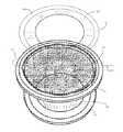
- FIG. 1illustrates one explanatory embodiment of a fluid collection container and lid configured in accordance with one or more embodiments of the invention.
- FIG. 2illustrates an exploded view of a fluid collection container with mesh layer configured in accordance with one or more embodiments of the invention.
- FIG. 3illustrates an exploded view of a fluid collection container with mesh layer and retention ring configured in accordance with one or more embodiments of the invention.
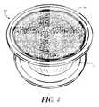
- FIG. 4illustrates one explanatory fluid collection container assembly configured in accordance with one or more embodiments of the invention.
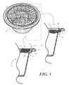
- FIG. 5illustrates one explanatory fluid collection container configured in accordance with one or more embodiments of the invention.
- FIG. 6illustrates alternate methods of coupling a mesh layer to a peripheral wall of one explanatory fluid collection container configured in accordance with one or more embodiments of the invention.
- FIG. 7illustrates splatter resistant properties of a fluid collection container configured in accordance with one or more embodiments of the invention.
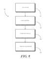
- FIG. 8illustrates one method of manufacturing a fluid collection container in accordance with one or more embodiments of the invention.
- FIG. 9illustrates one method of using a fluid collection container configured in accordance with one or more embodiments of the invention.
- Proper collection and disposal of certain fluids and other materialsis an important concern. For example, in the medical space, medical professionals pay special care to the appropriate disposition of blood, urine, tissue, and other biological materials that are obtained during medical procedures.
- the concern of proper collection and disposalstems from a desire to avoid contamination, possible infection, and exposure to such materials, as well as to abide by applicable rules and regulations concerning the disposal of such materials.
- the '314 patentattempts to provide a device configured for ready receipt and safe disposal of liquid wastes, and also to minimize the likelihood of splatter of the liquid wastes when introducing liquid into the container.
- the '314 patenttries to accomplish this by providing a bowl and lid.
- the lidincludes an opening through which liquids can be poured.
- the openingis sealed with a sheet of adhesive film that is permanently affixed at one end, and that can be peeled from the lid on the other end. A user peels back the adhesive film while liquids are poured into the opening.
- the adhesive filmis then pressed back across the opening to seal the container.
- Such a containersuffers from a number of deficiencies.
- the integrity of the seal between the adhesive film and the lidis dependent upon the user. A user in a hurry may insufficiently seal the adhesive film to the lid, thereby leaving an opening through which liquids may escape the container.
- a second exampleis more problematic. Since the adhesive film is tacky on one side and permanently affixed to the lid, a user must hold the film in a folded back position while dispensing liquids through the opening in the lid. Many users find that the folded adhesive film difficult to manage. Consequently, rather than peeling the adhesive film back, they simply remove the entire lid, thereby defeating the purpose of having a specialized container in the first place.
- Embodiments of the present inventionprovide a fluid collection container that offers many advantages over prior art designs.
- a first advantageis that the fluid entry into the container is large and wide. Rather than having a small aperture or specialized receptacle into which liquids are injected from a specialized device, like a syringe, embodiments of the present invention have large surfaces into which liquids may be injected, poured, or otherwise transferred. The large surface requires less accuracy in transferring liquids into the container when compared to prior art designs. Accordingly, a user may transfer fluids into the container more quickly and efficiently without any additional risk of spillage or contamination.
- a second advantageis that embodiments of the present invention provide splash-retarding elements that prevent splash back of fluids during transfer to the container.
- a mesh layer“gobbles” up liquid as it enters the container and eliminates or substantially prevents any splash back. Again, this feature allows a user to transfer fluids into the container more quickly and efficiently without any additional risk of spillage or contamination.
- a third advantageis that liquids can be introduced into the container at a wide variety of angles.
- Prior art containersrequired users to inject fluids into containers using syringes or other medical devices.
- the syringeshad to be oriented at just the proper angle to engage a specialized receptacle.
- small openingssuch as that found in the '314 patent required the user to hold the syringe at a particular angle.
- a usermay inject, pour, or otherwise transfer fluids into a container at any of a variety of angles without concern of spillage or splash back.
- the fluid collection container 100comprises a vessel 101 and a lid 102 configured for attachment to the vessel 101 .
- the vessel 101is defined by a plurality of surfaces having contours configured to form a hollow container, similar to a bowl or cask, which can be used to hold liquid.
- the lid 102is configured for selective attachment to the vessel 101 to form a closed fluid collection container. In one or more embodiments, when the lid 102 is attached to the vessel 101 , a leak-proof seal is formed between vessel 101 and lid 102 .
- Both the vessel 101 and the lid 102can be manufactured in a variety of ways.
- the vessel 101 and the lid 102can be manufactured from a thermoplastic material such as polypropylene by way of an injection molding process.
- the vessel 101 and lid 102can alternatively be thermally formed on a mold from a soft thermoplastic, such as styrene or polystyrene.
- the vessel 101 and lid 102can be poured on a mold using a quick setting plastic, epoxy, or resin. Other methods of manufacture will be obvious to those of ordinary skill in the art having the benefit of this disclosure.
- the plurality of surfaces defining the vessel 101includes a bottom surface 103 and a peripheral wall 104 .
- the explanatory vessel 101 shown in the figureshas a bottom surface 103 that is round.
- the bottom surface 103can be circular or oval, or alternatively can take other rounded shapes.
- the bottom surface 103can be triangular, rectangular, or multisided polygonal as well. Where the bottom surface 103 is polygonal, the corresponding peripheral wall 104 may include orthogonal angles.
- the peripheral wall 104is round and tapers outward as it extends distally upward from the bottom surface 103 . Such a taper can help the vessel 101 be extracted from a manufacturing tool. In this fashion, as shown in FIG. 1 , the bottom surface 103 and the peripheral wall 104 are arranged in a frustoconical geometry.
- the peripheral wall 104terminates in a contoured surface 105 .
- the contoured surface 105defines a stair-stepped flanged rim. The stair-stepped flanged rim will be shown and described in more detail with reference to FIG. 5 below.
- the lid 102includes an annular wall 106 disposed about a perimeter of the lid 102 .
- the annular wall 106defines a vessel receiving well 107 disposed beneath a central surface 108 of the lid 102 and within the annular wall 106 .
- the central surface 108spans an interior of the lid 102 .
- the central surface 108is configured with an inclined ring 109 disposed about the central surface 108 .
- the bottom surface 103 and the peripheral wall 104define an opening 110 disposed at an opposite end of the peripheral wall 104 from the bottom surface 103 , and an interior 111 disposed between the opening 110 , the bottom surface 103 , and the peripheral wall 104 .
- the opening 110is configured to receive liquids and other substances into the vessel 101 .
- the vesselis in a generally upright position, with the bottom surface 103 disposed below the opening 110 in three-dimensional space, liquids and other substances transferred to the vessel 101 through the opening 110 will be retained in the interior 111 of the vessel 101 .
- FIG. 2illustrated therein is the fluid collection container 100 of FIG. 1 with the lid 102 disposed beneath the vessel 101 .
- an inclined ring 109can be disposed about the central surface ( 108 ) of the lid 102 .
- the central surface ( 108 )can be configured to be substantially the same size as the bottom surface 103 of the vessel. Accordingly, when the vessel 101 is placed atop the lid 102 as shown in FIG. 2 , the inclined ring 109 can serve as a retention device that centers the vessel 101 into the lid 102 .
- FIG. 2is presented in an exploded view with a mesh conduit layer 201 disposed above the fluid collection container 100 .
- the mesh conduit layer 201will be coupled to the vessel 101 as shown in FIG. 4 , but is shown in an exploded view in FIG. 2 .
- the mesh conduit layer 201is referred to as “conduit” in that it forms a channel for conveying water or other fluids.
- the mesh conduit layer 201is a splash retarder in that it deflects liquid passing there through in directions other than that of incidence to prevent splash back. Said differently, the mesh conduit layer 201 disperses incident liquid to prevent is from splashing back toward the user.
- the mesh conduit layer 201is manufactured from a woven material.
- a hydrophilic materialsuch as cotton gauze manufactured with a loosely woven wave works well as the mesh conduit layer 201 .
- the mesh conduit layeris manufactured from a non-woven material.
- a hydrophobic materialsuch as spun glass—not unlike that used in inexpensive air filters used in ventilation systems—is used.
- mesh conduit layer 201can be used as well.
- a fiberspun non-woven materialsuch as ThinsulateTM manufactured by 3M.
- Other examples of materialsinclude spun cotton, spun glass, spun polyester, spun polyfibers, or spun nylon.
- “spunmelt” materialscan be used as the mesh conduit layer 201 .
- Spunmelt materialsare non-woven materials that are extruded while the extrusion heads are vibrated to form a non-woven material layer.
- the mesh conduit layer 201is manufactured from spunbond-meltblown-spunbond material.
- Other materialscan be used for the mesh conduit layer 201 include various woven, non-woven, hydroentangled materials, and/or combinations thereof, including spunlace, blends of polyester, polypropylene, polyethylene, urethane, and/or combinations thereof.
- the mesh conduit layer 201can be manufactured using various other methods than those described above, including a spunbond metblown spundbond method, and a spunbond metblown metblown spundbond method.
- the mesh conduit layer 201can be manufactured using a non-woven needle-punched process.
- a non-woven bunch of interlocking fibersare fed into a needle punch machine.
- the non-woven bunch of interlocking fiberscan be from a spunbond or carded web. Barbed felting needles then pass through the web of fibers, thereby causing one or more fibers to interlock.
- the mesh conduit layer 201when the mesh conduit layer 201 is coupled to the vessel 101 , it nests within the stair-stepped flanged rim of the contoured surface 105 . When coupled in this manner, the mesh conduit layer 201 spans the opening 110 to enclose the interior 111 of the vessel 101 . As the mesh conduit layer 201 is liquid permeable, despite enclosing the interior 111 of the vessel 101 , liquid can be transferred to the interior by pouring or dispensing the liquid through the mesh conduit layer 201 . As noted above, the mesh conduit layer 201 retards any splashing while the transfer occurs.
- FIG. 3illustrated therein is one example of how the mesh conduit layer 201 can be attached to the vessel 101 .
- the mesh conduit layer 201is disposed over the opening ( 110 ) of the vessel so as to span the opening ( 110 ) and enclose the interior of the vessel 101 .
- the coupling means shown in FIG. 3employs a retaining ring 301 that couples to the peripheral wall 104 atop the mesh conduit layer 201 . Accordingly, when the retaining ring 301 is coupled to the vessel at the contoured surface 105 , the mesh conduit layer 201 is disposed between the retaining ring 301 and the peripheral wall 104 , thereby holding the mesh conduit layer 201 in place.
- the retaining ring 301can be coupled to the contoured surface by an adhesive, thermal coupling, or other attachment methods.
- the retaining ring 301is configured to seat within the stair-stepped flanged rim by coupling to the peripheral wall 104 at the contoured surface 105 such that it seats beneath an upper limit 302 of the vessel 101 .
- the retaining ring 301will not interfere with placement of the lid 102 atop the vessel 101 .
- the lid 102attaches over the mesh conduit layer 201 , thereby sealing in any liquids in the interior ( 111 ) for convenient disposal.
- the retaining ring 301 of FIG. 3can offer an additional advantage in that it can serve to retain liquids within the vessel 101 should it tip to the side slightly.
- the retaining ringincludes an inclined surface 303 that extends from a peripheral wall coupling member 304 , which couples to the peripheral wall 104 at the contoured surface 105 , towards the interior ( 111 ) of the vessel 101 .
- the inclusion of the inclined surface 303helps to direct liquids into the vessel 101 .
- the retaining ring 301is shown coupled to the vessel 101 as a completed assembly 400 in FIG. 4 .
- a retaining ring 301is one example of a method of coupling the mesh conduit layer to the vessel 101 , other methods that do not require a retaining ring 301 can also be used. Turning to FIG. 5 , two such methods are shown.
- the mesh conduit layer 201is adhesively coupled to the contoured surface 105 of the vessel 101 .
- a layer of adhesive 503which may be a silicone or hot melt adhesive, is disposed between the mesh conduit layer 201 and the contoured surface 105 .
- the mesh conduit layer 201has been insert molded into the contoured surface 105 . This is accomplished by placing the mesh conduit layer 201 into a tool prior to injection molding a thermoplastic. As the thermoplastic passes about portions of the mesh conduit layer 201 , it becomes attached to the contoured surface 105 with layers 504 , 505 of material surrounding portions of the mesh conduit layer 201 .
- thermoplasticpasses about portions of the mesh conduit layer 201 , it becomes attached to the contoured surface 105 with layers 504 , 505 of material surrounding portions of the mesh conduit layer 201 .
- both the vessel 101 and the mesh conduit layer 201are manufactured from thermoplastics. In such an embodiment, a thermal process or heat bonding process can be used to weld the mesh conduit layer 201 to the vessel 101 .
- FIG. 5illustrates one embodiment of the contoured surface 105 when configured as a stair-stepped flanged rim.
- the stair-stepped flange rimincludes a ledge 506 , a tapered wall 507 , a flange support 508 , and a flange 509 .
- one or both of the flange support 508 and the flange 509are flexible so as to positively engage the lid ( 102 ) to form the closed fluid collection container.
- the mesh conduit layer 201is manufactured from hydrophobic, non-woven fibers 602 .
- the hydrophobic, non-woven fibers 602are spun glass that are liquid permeable and are configured to “gobble” liquids poured through them by slightly deflecting the liquid from their round cross-sectioned lengths to prevent splashing.
- the fibers forming the mesh conduit layerare opaque and are intermingled with a density sufficient to prevent a user from seeing through the mesh conduit layer 201 .
- Such an embodimentprovides an extra aesthetic appeal in that the user need not constantly look at liquids or other materials disposed within the interior 111 of the vessel 101 .
- Antimicrobial or toxin-neutralizing additivescan be added to the mesh conduit layer 201 to treat liquids that pass through as well.
- the vessel 101has disposed within its interior 111 a cache 603 of coagulant material.
- the coagulant materialis configured to cause liquids to change from a liquid state to a solid or semisolid state.
- the coagulant materialcan be a blood-specific coagulant configured to transform liquid blood into a gel to prevent spillage.
- the coagulantcan be a simple coagulant suitable for a variety of liquids. Such coagulants are routinely used as diaper gels in baby diapers.
- the cache 603comprises a simple hydrophilic material such as gauze.
- gauzeWhen the gauze absorbs the inserted liquid, it becomes effectively coagulated by passing into the fibers of the gauze.
- Other absorbent materialscan be substituted for the gauze as well.
- the cache 603 of coagulant materialoffers an advantage in that it counterbalances the vessel 101 when it becomes loaded. Said differently, once the cache 603 gets loaded, it lowers the center of gravity of the fluid collection container, which makes the vessel 101 harder to tip over. In many catheter procedures, a user will simply dump many containers of fluid into the vessel 101 . A lower center of gravity allows this to be accomplished more quickly with less spillage.
- FIG. 7illustrated therein are some of the many benefits of using a fluid collection container 700 configured in accordance with embodiments of the invention.
- a user 770is transferring liquid 771 through a mesh conduit layer 201 by way of a syringe 772 .
- the user 770may simply hold the syringe 772 generally above the mesh conduit layer 201 and allow the liquid 771 to flow.
- the fibers of the mesh conduit layer 201deflect portions 773 of the liquid that attempt to splash back toward the user 770 .
- FIG. 8illustrated therein is one method 800 of manufacturing a fluid collection container in accordance with one or more embodiments of the invention.
- the process stepshave largely been described in conjunction with the apparatus drawings above, and so will only be cursorily discussed here.
- a manufacturerobtains a fluid collection vessel. As noted above, this can be manufactured from an injection molding process, procured from a third-party vendor, or manufactured by other methods.
- the manufactureroptionally inserts a liquid trap into the interior of the vessel.
- the liquid trapis a cache of coagulant, such as a gelling agent or an absorbent material.
- the manufacturerattaches a mesh spatter-retarding layer to the vessel.
- the mesh layershould be liquid permeable, and should span an opening of the vessel to enclose its interior.
- various methodscan be used to couple the mesh layer to the vessel, including adhesive attachment, thermal attachment, attachment by an insert molding process, or other methods.
- the manufacturerobtains or manufactures a lid.
- the lidcan be packaged with the assembled vessel to form a fluid collection container ready for shipment to a user.
- the fluid collection containeris obtained from the manufacturer.
- the usertransfers a liquid substance to the fluid collection container by passing the liquid substance through the liquid-permeable mesh layer disposed across an opening of the fluid collection container.
- the useroptionally attaches a lid to the fluid collection container to form a sealed fluid collection container.
Landscapes
- Health & Medical Sciences (AREA)
- Engineering & Computer Science (AREA)
- Life Sciences & Earth Sciences (AREA)
- Surgery (AREA)
- Mechanical Engineering (AREA)
- Biomedical Technology (AREA)
- Nuclear Medicine, Radiotherapy & Molecular Imaging (AREA)
- Heart & Thoracic Surgery (AREA)
- Medical Informatics (AREA)
- Molecular Biology (AREA)
- Animal Behavior & Ethology (AREA)
- General Health & Medical Sciences (AREA)
- Public Health (AREA)
- Veterinary Medicine (AREA)
- Sampling And Sample Adjustment (AREA)
Abstract
Description
Claims (16)
Priority Applications (1)
| Application Number | Priority Date | Filing Date | Title |
|---|---|---|---|
| US13/283,421US8919554B2 (en) | 2011-10-27 | 2011-10-27 | Splash-retarding fluid collection system |
Applications Claiming Priority (1)
| Application Number | Priority Date | Filing Date | Title |
|---|---|---|---|
| US13/283,421US8919554B2 (en) | 2011-10-27 | 2011-10-27 | Splash-retarding fluid collection system |
Publications (2)
| Publication Number | Publication Date |
|---|---|
| US20130104989A1 US20130104989A1 (en) | 2013-05-02 |
| US8919554B2true US8919554B2 (en) | 2014-12-30 |
Family
ID=48171167
Family Applications (1)
| Application Number | Title | Priority Date | Filing Date |
|---|---|---|---|
| US13/283,421Active2032-09-12US8919554B2 (en) | 2011-10-27 | 2011-10-27 | Splash-retarding fluid collection system |
Country Status (1)
| Country | Link |
|---|---|
| US (1) | US8919554B2 (en) |
Cited By (6)
| Publication number | Priority date | Publication date | Assignee | Title |
|---|---|---|---|---|
| US20140246436A1 (en)* | 2011-04-13 | 2014-09-04 | Pablo Poch Figueroa | Polymorphic container for disposal of pathogens, biological, bio hazardous, anapatological and hospital materials with hermetic closure |
| USD874678S1 (en)* | 2017-08-31 | 2020-02-04 | Medline Industries, Inc. | Surgical kit |
| US20200154698A1 (en)* | 2017-07-20 | 2020-05-21 | Terumo Kabushiki Kaisha | Fragile object preserving device provided with sealing mechanism |
| USD1039712S1 (en) | 2022-09-14 | 2024-08-20 | Medline Industries, Lp | Medical procedure tray |
| USD1040625S1 (en) | 2021-04-15 | 2024-09-03 | Cascades Canada Ulc | Tray |
| US12220286B2 (en) | 2017-08-31 | 2025-02-11 | Medline Industries, Lp | Colored closing kit |
Citations (32)
| Publication number | Priority date | Publication date | Assignee | Title |
|---|---|---|---|---|
| US2511682A (en) | 1949-04-29 | 1950-06-13 | Russell C Allen | Cooking utensil cover |
| US4091956A (en) | 1977-06-21 | 1978-05-30 | Vecchio Fiore M | Splatter-proof lid |
| US4936449A (en)* | 1988-11-07 | 1990-06-26 | Conard Douglas S | Disposable sharps retaining and disposal device |
| US5024343A (en) | 1984-07-17 | 1991-06-18 | Lemelson Jerome H | Container assembly and method |
| US5047271A (en) | 1990-06-21 | 1991-09-10 | Fmt Holdings, Inc. | Apparatus and process relating to a preform and a container with geodesic reinforcement |
| US5305911A (en) | 1992-10-16 | 1994-04-26 | Sandusky Plastics, Inc. | Faceted container |
| US5350079A (en)* | 1993-03-01 | 1994-09-27 | Safety-Kleen Corp. | Safety cover assembly for open container |
| US5477897A (en) | 1994-05-17 | 1995-12-26 | Scofield; Brian S. | Oil recovery system |
| US5483999A (en) | 1993-03-15 | 1996-01-16 | Merit Medical Systems, Inc. | Waste collection system for containment and disposal of contaminated fluids |
| US5497892A (en) | 1994-02-24 | 1996-03-12 | Zojirushi Corporation | Filler caps for insulated urns and thermal containers |
| US5707173A (en)* | 1995-06-29 | 1998-01-13 | Advanced Medical Designs Inc. | Fluid collection device |
| US5769223A (en)* | 1994-03-01 | 1998-06-23 | Ohana Medical Concepts, Llc | Device for recapping needles and sharps |
| US5887739A (en) | 1997-10-03 | 1999-03-30 | Graham Packaging Company, L.P. | Ovalization and crush resistant container |
| US5967778A (en)* | 1998-01-28 | 1999-10-19 | Ultradent Products, Inc. | Apparatus and method for disinfecting endodontic instruments during use and storage |
| US6053314A (en)* | 1998-06-10 | 2000-04-25 | Deroyal Industries, Inc. | Receptacle for contaminated wastes |
| US6629602B1 (en)* | 2000-11-20 | 2003-10-07 | Becton, Dickinson And Company | Clear medical packaging |
| US6681925B2 (en)* | 2001-12-19 | 2004-01-27 | Ultradent Products, Inc. | Autoclavable and resealable endo file container |
| JP2004067214A (en) | 2002-08-08 | 2004-03-04 | Fukuoka Marumoto Kk | Assisting element for packaging |
| US6719017B1 (en) | 2002-01-10 | 2004-04-13 | Merit Medical Systems, Inc. | Waste collection system for containment and disposal of contaminated fluids |
| USD502993S1 (en) | 2002-01-10 | 2005-03-15 | Merit Medical Systems, Inc. | Waste collection container |
| JP2006123938A (en) | 2004-10-27 | 2006-05-18 | Fujimori Kogyo Co Ltd | Cap with funnel, spout member and packaging bag |
| US20070032764A1 (en) | 2005-08-05 | 2007-02-08 | Lampropoulos Fred P | Multi-part waste container apparatus |
| US7174928B1 (en) | 2005-08-05 | 2007-02-13 | Microsoft Corporation | Multi-part waste container apparatus |
| US7225927B2 (en) | 2003-07-17 | 2007-06-05 | Pactiv Corporation | Cup holder having frusto-conical cavities |
| US7458463B2 (en) | 2004-10-13 | 2008-12-02 | Merit Medical Systems, Inc. | Medical bio-waste container with integrated needle stop |
| US7507062B2 (en) | 2005-05-31 | 2009-03-24 | Societe Air France | Container for storage and transporting of a radome |
| US7597206B2 (en) | 2004-04-26 | 2009-10-06 | Dart Container Corporation | Container with one-step closing |
| JP2009280284A (en) | 2008-04-24 | 2009-12-03 | Toppan Printing Co Ltd | Packaging container and package using the same |
| US7644834B2 (en) | 2004-05-27 | 2010-01-12 | Navilyst Medical, Inc. | Splash minimizing lid for liquid waste receptacle |
| JP2011073701A (en) | 2009-09-29 | 2011-04-14 | Toppan Printing Co Ltd | Funnel part, packaging vessel using the same, and package |
| US7967147B2 (en) | 2006-11-07 | 2011-06-28 | Shin-Etsu Polymer Co., Ltd. | Substrate storage container |
| US8127963B2 (en) | 2004-12-16 | 2012-03-06 | Saint-Gobain Abrasives, Inc. | Liquid container system for a spray gun |
- 2011
- 2011-10-27USUS13/283,421patent/US8919554B2/enactiveActive
Patent Citations (33)
| Publication number | Priority date | Publication date | Assignee | Title |
|---|---|---|---|---|
| US2511682A (en) | 1949-04-29 | 1950-06-13 | Russell C Allen | Cooking utensil cover |
| US4091956A (en) | 1977-06-21 | 1978-05-30 | Vecchio Fiore M | Splatter-proof lid |
| US5024343A (en) | 1984-07-17 | 1991-06-18 | Lemelson Jerome H | Container assembly and method |
| US4936449A (en)* | 1988-11-07 | 1990-06-26 | Conard Douglas S | Disposable sharps retaining and disposal device |
| US5047271A (en) | 1990-06-21 | 1991-09-10 | Fmt Holdings, Inc. | Apparatus and process relating to a preform and a container with geodesic reinforcement |
| US5305911A (en) | 1992-10-16 | 1994-04-26 | Sandusky Plastics, Inc. | Faceted container |
| US5350079A (en)* | 1993-03-01 | 1994-09-27 | Safety-Kleen Corp. | Safety cover assembly for open container |
| US5483999A (en) | 1993-03-15 | 1996-01-16 | Merit Medical Systems, Inc. | Waste collection system for containment and disposal of contaminated fluids |
| US5497892A (en) | 1994-02-24 | 1996-03-12 | Zojirushi Corporation | Filler caps for insulated urns and thermal containers |
| US5769223A (en)* | 1994-03-01 | 1998-06-23 | Ohana Medical Concepts, Llc | Device for recapping needles and sharps |
| US5477897A (en) | 1994-05-17 | 1995-12-26 | Scofield; Brian S. | Oil recovery system |
| US5707173A (en)* | 1995-06-29 | 1998-01-13 | Advanced Medical Designs Inc. | Fluid collection device |
| US5887739A (en) | 1997-10-03 | 1999-03-30 | Graham Packaging Company, L.P. | Ovalization and crush resistant container |
| US5967778A (en)* | 1998-01-28 | 1999-10-19 | Ultradent Products, Inc. | Apparatus and method for disinfecting endodontic instruments during use and storage |
| US6053314A (en)* | 1998-06-10 | 2000-04-25 | Deroyal Industries, Inc. | Receptacle for contaminated wastes |
| US6629602B1 (en)* | 2000-11-20 | 2003-10-07 | Becton, Dickinson And Company | Clear medical packaging |
| US6681925B2 (en)* | 2001-12-19 | 2004-01-27 | Ultradent Products, Inc. | Autoclavable and resealable endo file container |
| US6719017B1 (en) | 2002-01-10 | 2004-04-13 | Merit Medical Systems, Inc. | Waste collection system for containment and disposal of contaminated fluids |
| USD502993S1 (en) | 2002-01-10 | 2005-03-15 | Merit Medical Systems, Inc. | Waste collection container |
| JP2004067214A (en) | 2002-08-08 | 2004-03-04 | Fukuoka Marumoto Kk | Assisting element for packaging |
| US7225927B2 (en) | 2003-07-17 | 2007-06-05 | Pactiv Corporation | Cup holder having frusto-conical cavities |
| US7597206B2 (en) | 2004-04-26 | 2009-10-06 | Dart Container Corporation | Container with one-step closing |
| US7644834B2 (en) | 2004-05-27 | 2010-01-12 | Navilyst Medical, Inc. | Splash minimizing lid for liquid waste receptacle |
| US7458463B2 (en) | 2004-10-13 | 2008-12-02 | Merit Medical Systems, Inc. | Medical bio-waste container with integrated needle stop |
| JP2006123938A (en) | 2004-10-27 | 2006-05-18 | Fujimori Kogyo Co Ltd | Cap with funnel, spout member and packaging bag |
| US8127963B2 (en) | 2004-12-16 | 2012-03-06 | Saint-Gobain Abrasives, Inc. | Liquid container system for a spray gun |
| US7507062B2 (en) | 2005-05-31 | 2009-03-24 | Societe Air France | Container for storage and transporting of a radome |
| US20070032764A1 (en) | 2005-08-05 | 2007-02-08 | Lampropoulos Fred P | Multi-part waste container apparatus |
| US7665491B2 (en) | 2005-08-05 | 2010-02-23 | Merit Medical Systems, Inc. | Multi-part waste container apparatus |
| US7174928B1 (en) | 2005-08-05 | 2007-02-13 | Microsoft Corporation | Multi-part waste container apparatus |
| US7967147B2 (en) | 2006-11-07 | 2011-06-28 | Shin-Etsu Polymer Co., Ltd. | Substrate storage container |
| JP2009280284A (en) | 2008-04-24 | 2009-12-03 | Toppan Printing Co Ltd | Packaging container and package using the same |
| JP2011073701A (en) | 2009-09-29 | 2011-04-14 | Toppan Printing Co Ltd | Funnel part, packaging vessel using the same, and package |
Non-Patent Citations (3)
| Title |
|---|
| Choi, Hyun G., "PCT Search Report and Written Opinion", PCT/US2013/050708; Filed Jul. 16, 2013; Mailed Oct. 7, 2013. |
| Warner, Brandon J., "Final OA", U.S. Appl. No. 13/559,285, filed Jul. 26, 2012; Mailed Jul. 31, 2013. |
| Warner, Brandon J., "NonFinal OA", U.S. Appl. No. 13/559,285, filed Jul. 26, 2012; Mailed Apr. 11, 2013. |
Cited By (7)
| Publication number | Priority date | Publication date | Assignee | Title |
|---|---|---|---|---|
| US20140246436A1 (en)* | 2011-04-13 | 2014-09-04 | Pablo Poch Figueroa | Polymorphic container for disposal of pathogens, biological, bio hazardous, anapatological and hospital materials with hermetic closure |
| US20200154698A1 (en)* | 2017-07-20 | 2020-05-21 | Terumo Kabushiki Kaisha | Fragile object preserving device provided with sealing mechanism |
| US12016329B2 (en)* | 2017-07-20 | 2024-06-25 | Terumo Kabushiki Kaisha | Fragile object preserving device provided with sealing mechanism |
| USD874678S1 (en)* | 2017-08-31 | 2020-02-04 | Medline Industries, Inc. | Surgical kit |
| US12220286B2 (en) | 2017-08-31 | 2025-02-11 | Medline Industries, Lp | Colored closing kit |
| USD1040625S1 (en) | 2021-04-15 | 2024-09-03 | Cascades Canada Ulc | Tray |
| USD1039712S1 (en) | 2022-09-14 | 2024-08-20 | Medline Industries, Lp | Medical procedure tray |
Also Published As
| Publication number | Publication date |
|---|---|
| US20130104989A1 (en) | 2013-05-02 |
Similar Documents
| Publication | Publication Date | Title |
|---|---|---|
| US10111989B2 (en) | Splash-retarding fluid collection system | |
| US8919554B2 (en) | Splash-retarding fluid collection system | |
| US5707173A (en) | Fluid collection device | |
| US7665491B2 (en) | Multi-part waste container apparatus | |
| US9474863B2 (en) | Multi-purpose syringe | |
| US6719017B1 (en) | Waste collection system for containment and disposal of contaminated fluids | |
| US5483999A (en) | Waste collection system for containment and disposal of contaminated fluids | |
| US9839479B2 (en) | Medical waste containment device | |
| EP3357525B1 (en) | Medical device packaging container, medical device package, and cylindrical outer package for prefilled syringe | |
| US20090030379A1 (en) | Drain Bag Valve And Shield | |
| JP3398098B2 (en) | Float for liquid waste treatment equipment | |
| JP3226672U (en) | Absorbent material storage device | |
| GB2121016A (en) | An evacuation device for sterile containers | |
| CN108697062B (en) | Urine containers and toilets | |
| JP3722518B2 (en) | Method of manufacturing a processing unit used in a liquid waste processing apparatus | |
| US7458463B2 (en) | Medical bio-waste container with integrated needle stop | |
| US20020049416A1 (en) | Disposable bag for storing excrement and solid and liquid residues for use in hospital containers | |
| KR102369576B1 (en) | Medical waste collecting apparatus including main vessel and buffer vessel | |
| US20050218032A1 (en) | Sterile cleaning kit | |
| JP6995560B2 (en) | Waste liquid collection container | |
| JP6968654B2 (en) | Waste liquid collection container | |
| WO2022263961A1 (en) | Granulate dispenser for flexible and tetrapak containers with ergonomic grip and lower end with sharp geometry | |
| JPH0736654Y2 (en) | Waste liquid treatment container | |
| JPH02157083A (en) | Container for processing waste fluids containing body fluids | |
| US20190000583A1 (en) | Medical Waste Container Lining Device and Method |
Legal Events
| Date | Code | Title | Description |
|---|---|---|---|
| AS | Assignment | Owner name:MEDLINE INDUSTRIES, INC., ILLINOIS Free format text:CORRECTIVE ASSIGNMENT TO CORRECT THE DATE TYPOGRAPHICAL ERROR - DATE ON ASSIGNMENT AND COVER SHEET WAS 10/26/2011 AND SHOULD BE 10/27/2011 PREVIOUSLY RECORDED ON REEL 027135 FRAME 0981. ASSIGNOR(S) HEREBY CONFIRMS THE WITH EXCEPTION OF THE FILING DATE - CORRECTED TO 10/27/2011 UNDER POWER OF ATTORNEY IN ASSIGNMENT.;ASSIGNOR:HULDIN, NELSON L., MR.;REEL/FRAME:027136/0950 Effective date:20111027 Owner name:MEDLINE INDUSTRIES, INC., ILLINOIS Free format text:ASSIGNMENT OF ASSIGNORS INTEREST;ASSIGNOR:HULDIN, NELSON L., MR.;REEL/FRAME:027135/0981 Effective date:20111026 | |
| STCF | Information on status: patent grant | Free format text:PATENTED CASE | |
| MAFP | Maintenance fee payment | Free format text:PAYMENT OF MAINTENANCE FEE, 4TH YEAR, LARGE ENTITY (ORIGINAL EVENT CODE: M1551) Year of fee payment:4 | |
| AS | Assignment | Owner name:BANK OF AMERICA, N.A., TEXAS Free format text:SECURITY INTEREST;ASSIGNOR:MEDLINE INDUSTRIES, LP;REEL/FRAME:058040/0001 Effective date:20211021 Owner name:WILMINGTON TRUST, NATIONAL ASSOCIATION, MINNESOTA Free format text:SECURITY INTEREST;ASSIGNOR:MEDLINE INDUSTRIES, LP;REEL/FRAME:057927/0091 Effective date:20211021 | |
| AS | Assignment | Owner name:MEDLINE INDUSTRIES, LP, ILLINOIS Free format text:CONVERSION OF ENTITY FROM CORPORATION TO LIMITED PARTNERSHIP;ASSIGNOR:MEDLINE INDUSTRIES, INC.;REEL/FRAME:057977/0567 Effective date:20210907 | |
| MAFP | Maintenance fee payment | Free format text:PAYMENT OF MAINTENANCE FEE, 8TH YEAR, LARGE ENTITY (ORIGINAL EVENT CODE: M1552); ENTITY STATUS OF PATENT OWNER: LARGE ENTITY Year of fee payment:8 | |
| AS | Assignment | Owner name:WILMINGTON TRUST, NATIONAL ASSOCIATION, AS NOTES COLLATERAL AGENT, MINNESOTA Free format text:PATENT SECURITY AGREEMENT;ASSIGNOR:MEDLINE INDUSTRIES, LP;REEL/FRAME:071672/0100 Effective date:20240327 |