US8919379B2 - Plug switch outlet mechanism - Google Patents
Plug switch outlet mechanismDownload PDFInfo
- Publication number
- US8919379B2 US8919379B2US13/583,178US201113583178AUS8919379B2US 8919379 B2US8919379 B2US 8919379B2US 201113583178 AUS201113583178 AUS 201113583178AUS 8919379 B2US8919379 B2US 8919379B2
- Authority
- US
- United States
- Prior art keywords
- switch
- waterway
- shower
- push plate
- plug
- Prior art date
- Legal status (The legal status is an assumption and is not a legal conclusion. Google has not performed a legal analysis and makes no representation as to the accuracy of the status listed.)
- Active, expires
Links
- XLYOFNOQVPJJNP-UHFFFAOYSA-NwaterSubstancesOXLYOFNOQVPJJNP-UHFFFAOYSA-N0.000claimsabstractdescription46
- 238000007789sealingMethods0.000claimsdescription25
- 230000013011matingEffects0.000claims1
- 238000005516engineering processMethods0.000description3
- 239000010985leatherSubstances0.000description3
- 238000012856packingMethods0.000description3
- 230000015556catabolic processEffects0.000description2
- 230000000694effectsEffects0.000description2
- 230000001105regulatory effectEffects0.000description2
- 238000000034methodMethods0.000description1
- 238000012986modificationMethods0.000description1
- 230000004048modificationEffects0.000description1
- 125000006850spacer groupChemical group0.000description1
Images


Classifications
- B—PERFORMING OPERATIONS; TRANSPORTING
- B05—SPRAYING OR ATOMISING IN GENERAL; APPLYING FLUENT MATERIALS TO SURFACES, IN GENERAL
- B05B—SPRAYING APPARATUS; ATOMISING APPARATUS; NOZZLES
- B05B1/00—Nozzles, spray heads or other outlets, with or without auxiliary devices such as valves, heating means
- B05B1/14—Nozzles, spray heads or other outlets, with or without auxiliary devices such as valves, heating means with multiple outlet openings; with strainers in or outside the outlet opening
- B05B1/16—Nozzles, spray heads or other outlets, with or without auxiliary devices such as valves, heating means with multiple outlet openings; with strainers in or outside the outlet opening having selectively- effective outlets
- B05B1/1609—Nozzles, spray heads or other outlets, with or without auxiliary devices such as valves, heating means with multiple outlet openings; with strainers in or outside the outlet opening having selectively- effective outlets with a selecting mechanism comprising a lift valve
- B05B1/1618—Nozzles, spray heads or other outlets, with or without auxiliary devices such as valves, heating means with multiple outlet openings; with strainers in or outside the outlet opening having selectively- effective outlets with a selecting mechanism comprising a lift valve where said valve is a double-seat lift valve
- E—FIXED CONSTRUCTIONS
- E03—WATER SUPPLY; SEWERAGE
- E03C—DOMESTIC PLUMBING INSTALLATIONS FOR FRESH WATER OR WASTE WATER; SINKS
- E03C1/00—Domestic plumbing installations for fresh water or waste water; Sinks
- E03C1/02—Plumbing installations for fresh water
- E03C1/04—Water-basin installations specially adapted to wash-basins or baths
- E03C1/0408—Water installations especially for showers
- E—FIXED CONSTRUCTIONS
- E03—WATER SUPPLY; SEWERAGE
- E03C—DOMESTIC PLUMBING INSTALLATIONS FOR FRESH WATER OR WASTE WATER; SINKS
- E03C1/00—Domestic plumbing installations for fresh water or waste water; Sinks
- E03C1/02—Plumbing installations for fresh water
- E03C1/06—Devices for suspending or supporting the supply pipe or supply hose of a shower-bath
- F—MECHANICAL ENGINEERING; LIGHTING; HEATING; WEAPONS; BLASTING
- F16—ENGINEERING ELEMENTS AND UNITS; GENERAL MEASURES FOR PRODUCING AND MAINTAINING EFFECTIVE FUNCTIONING OF MACHINES OR INSTALLATIONS; THERMAL INSULATION IN GENERAL
- F16K—VALVES; TAPS; COCKS; ACTUATING-FLOATS; DEVICES FOR VENTING OR AERATING
- F16K11/00—Multiple-way valves, e.g. mixing valves; Pipe fittings incorporating such valves
- F16K11/02—Multiple-way valves, e.g. mixing valves; Pipe fittings incorporating such valves with all movable sealing faces moving as one unit
- F16K11/04—Multiple-way valves, e.g. mixing valves; Pipe fittings incorporating such valves with all movable sealing faces moving as one unit comprising only lift valves
- F16K11/056—Multiple-way valves, e.g. mixing valves; Pipe fittings incorporating such valves with all movable sealing faces moving as one unit comprising only lift valves with ball-shaped valve members
- F—MECHANICAL ENGINEERING; LIGHTING; HEATING; WEAPONS; BLASTING
- F16—ENGINEERING ELEMENTS AND UNITS; GENERAL MEASURES FOR PRODUCING AND MAINTAINING EFFECTIVE FUNCTIONING OF MACHINES OR INSTALLATIONS; THERMAL INSULATION IN GENERAL
- F16K—VALVES; TAPS; COCKS; ACTUATING-FLOATS; DEVICES FOR VENTING OR AERATING
- F16K11/00—Multiple-way valves, e.g. mixing valves; Pipe fittings incorporating such valves
- F16K11/02—Multiple-way valves, e.g. mixing valves; Pipe fittings incorporating such valves with all movable sealing faces moving as one unit
- F16K11/06—Multiple-way valves, e.g. mixing valves; Pipe fittings incorporating such valves with all movable sealing faces moving as one unit comprising only sliding valves, i.e. sliding closure elements
- F16K11/065—Multiple-way valves, e.g. mixing valves; Pipe fittings incorporating such valves with all movable sealing faces moving as one unit comprising only sliding valves, i.e. sliding closure elements with linearly sliding closure members
- B—PERFORMING OPERATIONS; TRANSPORTING
- B05—SPRAYING OR ATOMISING IN GENERAL; APPLYING FLUENT MATERIALS TO SURFACES, IN GENERAL
- B05B—SPRAYING APPARATUS; ATOMISING APPARATUS; NOZZLES
- B05B1/00—Nozzles, spray heads or other outlets, with or without auxiliary devices such as valves, heating means
- B05B1/14—Nozzles, spray heads or other outlets, with or without auxiliary devices such as valves, heating means with multiple outlet openings; with strainers in or outside the outlet opening
- B05B1/18—Roses; Shower heads
- Y—GENERAL TAGGING OF NEW TECHNOLOGICAL DEVELOPMENTS; GENERAL TAGGING OF CROSS-SECTIONAL TECHNOLOGIES SPANNING OVER SEVERAL SECTIONS OF THE IPC; TECHNICAL SUBJECTS COVERED BY FORMER USPC CROSS-REFERENCE ART COLLECTIONS [XRACs] AND DIGESTS
- Y10—TECHNICAL SUBJECTS COVERED BY FORMER USPC
- Y10T—TECHNICAL SUBJECTS COVERED BY FORMER US CLASSIFICATION
- Y10T137/00—Fluid handling
- Y10T137/8593—Systems
- Y10T137/86493—Multi-way valve unit
- Y10T137/86879—Reciprocating valve unit
- Y—GENERAL TAGGING OF NEW TECHNOLOGICAL DEVELOPMENTS; GENERAL TAGGING OF CROSS-SECTIONAL TECHNOLOGIES SPANNING OVER SEVERAL SECTIONS OF THE IPC; TECHNICAL SUBJECTS COVERED BY FORMER USPC CROSS-REFERENCE ART COLLECTIONS [XRACs] AND DIGESTS
- Y10—TECHNICAL SUBJECTS COVERED BY FORMER USPC
- Y10T—TECHNICAL SUBJECTS COVERED BY FORMER US CLASSIFICATION
- Y10T137/00—Fluid handling
- Y10T137/8593—Systems
- Y10T137/877—With flow control means for branched passages
- Y10T137/87788—With valve or movable deflector at junction
- Y—GENERAL TAGGING OF NEW TECHNOLOGICAL DEVELOPMENTS; GENERAL TAGGING OF CROSS-SECTIONAL TECHNOLOGIES SPANNING OVER SEVERAL SECTIONS OF THE IPC; TECHNICAL SUBJECTS COVERED BY FORMER USPC CROSS-REFERENCE ART COLLECTIONS [XRACs] AND DIGESTS
- Y10—TECHNICAL SUBJECTS COVERED BY FORMER USPC
- Y10T—TECHNICAL SUBJECTS COVERED BY FORMER US CLASSIFICATION
- Y10T137/00—Fluid handling
- Y10T137/8593—Systems
- Y10T137/877—With flow control means for branched passages
- Y10T137/87829—Biased valve
- Y10T137/87837—Spring bias
- Y10T137/87861—Spring coaxial with valve
- Y10T137/87869—Biased open
Definitions
- the present inventionrelates to an outlet mechanism, especially to a plug switch outlet mechanism.
- Outlet unit combined with head shower and hand showeris provided as well. It's provided with an outlet unit combined with a fixed shower and a hand shower disclosed in American patent database with application number of US20050098661, disclosed in Chinese patent database with application number of CN200580036723, announced in Chinese patent database with application number of CN200620065207.8, disclosed in American patent database with application number of US20070022528.
- the outlet of the fixed showeris disposed with a plug groove for hand shower. It has a regulating switch button disposed in the inlet end and at the back side of the fixed unit of the shower for the switch of the outlet function of the fixed shower and the hand shower.
- the present inventionis provided with a plug switch outlet mechanism, which overcomes the problems of the existing technology.
- a plug switch outlet mechanismincludes:
- a first showercompositing a fixed unit, a first switch mechanism inside the fixed unit, an outlet connected to the fixed unit and a socket outside the fixed unit;
- the fixed unitis disposed with two waterways and an inlet waterway connected to the external water source, one of the waterways is connected to the outlet, the socket is disposed with a switch, the switch is driving and connected to the first switch mechanism for driving the first switch mechanism when touched to make the two waterways switched to connect to the inlet waterway;
- a second showerconnected to the other waterway, the second shower is coupled to the socket and can be plugged into the socket, when the second shower is inserted into the socket or pulled away from the socket, the switch is touched.
- the socketis fixed to the middle of the fixed unit.
- the outletis rotated and connected to the fixed unit, the outlet is disposed with several outlet functions, each outlet function is disposed with a water diversion hole corresponding to the waterway, the switch of the outlet function of the first shower is realized by rotating the outlet.
- the fixed unitfurther includes a sliding hole and a control cavity connected between the inlet waterway and the waterways, the inner end of the sliding hole is connected to the control cavity;
- the first switch mechanismis disposed with a push plate and a sealing, the push plate is sliding and connected to the sliding hole, the sealing is disposed in the inner end of the push plate, the switch is pivot jointed to the socket, the switch withstands the outer end of the push plate; the switch withstands the push plate and drives the push plate slide between a first position and a second position, the other waterway is sealed by the sealing and the inlet waterway is connected to the waterway when the push plate is situated in the first position, the waterway is sealed by the sealing and the inlet waterway is connected to the other waterway when the push plate is situated in the second position.
- the socketis disposed with a plug surface according to the second shower, the plug surface is concaved to form an accommodating groove, which is connected to the outer opening of the sliding hole, one end of the switch is pivot jointed to the accommodating groove, the other end of the switch withstands the outer end of the push plate.
- an elastic pieceis disposed between the push plate and the fixed unit, the elastic piece produces elastic force, and the direction of the elastic force is from the first position to the second position, the elastic force works on the push plate.
- the first showeris a head shower
- the second showeris a hand shower
- the hand showeris connected to the other waterway of the head shower through a flexible tube.
- the fixed unitincludes a ball unit, a body, a main body, an upper water diversion body, a joint and a press plate:
- the bodyis opened with a first throughout hole of inner and outer in the middle of the body and a second throughout hole of inner and outer;
- the main bodyis disposed with an inlet waterway formed from the top surface concaved downwards, a sliding groove formed from the side surface concaved inwards, a first watercourse, a second watercourse, a water groove formed from the side surface of the main body concaved inwards, a connection waterway connected to the second watercourse and the water groove;
- the upper water diversion bodyis opened with a water channel of throughout, the joint is passed through the second throughout hole, one end of the joint is connected to the water groove, while the other end is extended out of the body to connect to the hand shower through flexible tube;
- the press plateis fixed to the end of the sliding groove.
- the top surface of the upper water and the bottom surface of the main bodyare welded together; the water channel is connected to the first watercourse to form the first waterway.
- the entries of the first watercourse and the second watercourseare disposed on the inner surface of the sliding groove.
- the present inventionhas advantages as below: firstly, when the second shower is inserted into the socket or pulled away from the socket, the switch of the two waterways to connect to the inlet waterway is realized by the first switch mechanism touched by the switch, the selection is simple, fast and convenient; secondly, the socket is fixed to the middle of the fixed unit, the outlet is of variety, making it convenient for the standardization of the components, the outlet follows the widely usage pattern; thirdly, the switch of the outlet function of the head shower is realized by the rotation between the outlet and the fixed unit, which is convenient for the user; fourthly, the switch of the two waterways is realized through the switch, the push plate and the sealing with simple mechanism; fifthly, an elastic piece is disposed between the push plate and the fixed unit, making sure that the switch is touched when the second shower is pulled away from the socket or inserted into the socket; sixthly, one end of the switch is pivot jointed to the accommodating groove while the other end withstands the outer end of the push plate, making sure that the switch is touched when the second shower is
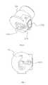
- FIG. 1illustrates the structure of the plug switch outlet mechanism of the preferred embodiment of the present invention when water is flowing through the head shower.
- FIG. 2illustrates the structure of the plug switch outlet mechanism of the preferred embodiment of the present invention when the water is flowing through the hand shower.
- FIG. 3illustrates the structure of the head shower of the plug switch outlet mechanism of the preferred embodiment of the present invention.
- FIG. 4illustrates the breakdown structure of the head shower of the plug switch outlet mechanism of the preferred embodiment of the present invention.
- FIG. 5illustrates the breakdown structure of the outlet of the head shower of the head shower of the plug switch outlet mechanism of the preferred embodiment of the present invention.
- FIG. 6illustrates the structure of the main body of the head shower of the head shower of the plug switch outlet mechanism of the preferred embodiment of the present invention.
- FIG. 7illustrates the bottom view of the main body of the head shower of the head shower of the plug switch outlet mechanism of the preferred embodiment of the present invention.
- FIG. 8illustrates the sectional view of the main body of the head shower of the head shower of the plug switch outlet mechanism of the preferred embodiment of the present invention.
- FIG. 9illustrates the sectional view of E-E of the FIG. 8 .
- FIG. 10illustrates the structure of the upper water diversion body of the head shower of the plug switch outlet mechanism of the preferred embodiment of the present invention.
- FIG. 11illustrates the structure of the assembly of the upper water diversion body and the main body of the head shower of the plug switch outlet mechanism of the preferred embodiment of the present invention.
- FIG. 12illustrates the sectional view of the head shower of the plug switch outlet mechanism of the preferred embodiment of the present invention when the water is flowing through the head shower.
- FIG. 13illustrates the sectional view of the A-A of the FIG. 12 .
- FIG. 14illustrates the sectional view of the head shower of the plug switch outlet mechanism of the preferred embodiment of the present invention when the water is flowing through the hand shower.
- FIG. 15illustrates the sectional view of the B-B of the FIG. 14 .
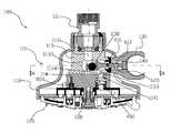
- FIG. 1Please refer to the FIG. 1 to the FIG. 15 with the plug switch outlet mechanism of the preferred embodiment of the present invention.
- the plug switch outlet mechanismincludes a head shower 100 and a hand shower 200 .
- the head shower 100includes a fixed unit 110 , a first switch mechanism, an outlet 120 , a socket 130 and a switch 140 .
- the fixed unit 110includes a ball unit 111 , a body 112 , a main body 113 , an upper water diversion body 114 , a joint 115 and a press plate 116 .
- the body 112is convex shaped; the upper of the body 112 is fixed to a supporting arm 700 through the ball unit 111 .
- the ball unit 111is fixed to the supporting arm 700 while the body 112 is fixed to the ball unit 111 .
- the body 112is opened with a first throughout hole 1121 of throughout inner and outer in the middle of the body 112 and a second throughout hole 1122 of throughout inner and outer.
- the main body 113is disposed with an inlet waterway 1131 formed from the top surface of the main body 113 concaved downwards, a sliding groove 1132 formed from the side surface of the main body 113 concaved inwards, a first watercourse 1133 , a second watercourse 1134 , a water groove 1135 formed from the side surface of the main body 113 concaved inwards, a connection waterway connected the second watercourse 1134 and the water groove 1135 , the entries of the first watercourse 1133 and the second watercourse 1134 are disposed on the inner surface of the sliding groove 1132 .
- the upper water diversion body 114is opened with a water channel 1141 of throughout; the top surface of the upper water diversion body 114 and the bottom surface of the main body 113 are welded together.
- the water channel 1141is connected to the first watercourse 1133 to form the first waterway.
- the joint 115is passed through the second throughout hole 1122 , one end of the joint 115 is connected to the water groove 1135 , while the other end is extended out of the body 112 to connect to the hand shower 200 through flexible tube 300 .
- the second watercourse 1134 , the connection channel, the water groove 1135 and the joint 115are formed the second waterway.
- the press plate 116is fixed to the end of the sliding groove 1132 .
- the press plate 116is disposed with a throughout hole according to the sliding groove 1132 , the sliding groove 1132 and the throughout hole are formed the sliding hole, which is corresponding to the first throughout hole 1121 .
- the outlet 120is rotated and connected inside the body 112 .
- the outlet 120has several outlet functions, each outlet functions is disposed with a water diversion hole corresponding to the lower end of the water channel 141 of the first waterway, so one of the water diversion hole is connected to the water channel 1141 when the outlet 120 is rotated to realize the switch of the outlet function of the head shower.
- the outlet functionis bubble water, massage water or shower water and so on.
- the cover 127is disposed with a convex button for the selection of the different outlet functions of the head shower for the user.
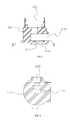
- itis better to disposed a packing leather 400 in the lower end of the water channel 141 of the first waterway and a spring 500 withstanding between the packing leather 400 and the water channel to make the packing leather 400 sealed and contacted to the outlet, making sure axial sealing and radial sealing.
- the position mechanism 800includes a groove disposed below the upper water diversion body, a withstand spring inside the groove, a pin connected to the withstand spring and several position holes disposed on the outlet 120 , the position holes are corresponding to the water diversion holes one by one, the pin is corresponding to the position hole and works on the position hole to realize position.
- the socket 130is passed through the first throughout hole 1121 and locked to the main body 113 through a catch arm 131 , making the socket 130 and the fixed unit 110 form a fixed connection relationship.
- the plug surface of the socket 130is concaved downward to form an accommodating groove 132 , which is corresponding to the sliding hole.
- one end of the switch 140is pivot jointed to the accommodating groove 132 and rotating between the third position and the fourth position, the fourth position is referred to the other end of the switch 140 extended out of the accommodating groove 132 , the third position is referred to the other end of the switch 140 drawn back to the accommodating groove 132 .
- the hand shower 200works on the other end of the switch 140 to make the switch 140 rotate from the fourth position to the third position.
- the switch 140rotates from the third position to the fourth position with the effect of the elastic piece 610 .
- the direction from one end to the other endis the same as the plug direction of the hand shower.
- the first switch mechanismincludes an elastic piece 610 , a push plate 620 and a sealing 630 .
- the push plate 620is connected to the sliding hole and sliding between the first position and the second position.
- the elastic piece 610is disposed between the push plate 620 and the fixed unit, the elastic piece 610 produces elastic force, the direction of the elastic force is from the first position to the second position, the elastic force works on the push plate 620 .
- the outer end of the push plate 620withstands the switch 140 , the inner end is disposed with a connection base 621 , the sealing 630 is a closure ball disposed inside the connection base 621 .
- the push plate 620When the switch 140 is situated in the third position, the push plate 620 is situated in the first position; when the switch 140 is situated in the fourth position, the push plate 620 is situated in the second position.
- the sealing 630closes the entry of the second watercourse 1134 of the second waterway, the inlet waterway 1131 is connected to the first waterway, the water flows out of the head shower 100 ;
- the push plate 620is situated in the second position, the first waterway is sealed by the sealing 630 , the inlet waterway 1131 is connected to the second waterway, the water flows out of the hand shower 200 .
- the hand shower 200is connected to the joint 115 of the second waterway through the flexible tube 300 .
- the hand shower 200is coupled to the socket 130 and can insert into the socket 130 .
- the hand shower 200works on the switch 140 , making it rotated from the fourth position to the third position, meanwhile the push plate 620 moves from the second position to the first position, the elastic piece 310 is pressed to store energy, the entry of the second watercourse 1134 of the second waterway is sealed by the sealing 630 .
- the inlet waterway 1131is connected to the first waterway, the water flows out of the head shower 100 .
- the outlet function of the head shower 100is switched by rotating the outlet 130 . Please refer to the FIG. 1 , FIG. 12 and FIG. 13 .
- the switch 140When the hand shower 200 is pulled away from the socket 130 , the switch 140 is rotated from the third position to the fourth position with the effect of the elastic force of the elastic piece 610 , meanwhile the push plate 620 moves from the first position to the second position, the entry of the first watercourse 1133 of the first waterway is sealed by the sealing 630 , the inlet waterway 1131 is connected to the second waterway, the water flows out of the hand shower 200 .
- FIG. 2 , FIG. 14 and FIG. 15Please refer to the FIG. 2 , FIG. 14 and FIG. 15 .
- the present inventionis provided with a plug switch outlet mechanism, when the second shower is inserted into the socket or pulled away from the socket, the switch of the two waterways to connect to the inlet waterway is realized by the first switch mechanism touched by the switch, the selection is simple, fast and convenient.
Landscapes
- Engineering & Computer Science (AREA)
- General Engineering & Computer Science (AREA)
- Health & Medical Sciences (AREA)
- Life Sciences & Earth Sciences (AREA)
- Hydrology & Water Resources (AREA)
- Public Health (AREA)
- Water Supply & Treatment (AREA)
- Mechanical Engineering (AREA)
- Bathtubs, Showers, And Their Attachments (AREA)
- Nozzles (AREA)
- Domestic Plumbing Installations (AREA)
Abstract
Description
Claims (18)
Applications Claiming Priority (7)
| Application Number | Priority Date | Filing Date | Title |
|---|---|---|---|
| CN 201010120616CN101862713B (en) | 2010-03-09 | 2010-03-09 | Triggering-switchover water outlet mechanism |
| CN201020126525U | 2010-03-09 | ||
| CN201010120616 | 2010-03-09 | ||
| CN201010120616.4 | 2010-03-09 | ||
| CN201020126525.7 | 2010-03-09 | ||
| CN2010201265257UCN201603636U (en) | 2010-03-09 | 2010-03-09 | Plugging-type switching water outlet mechanism |
| PCT/CN2011/071599WO2011110081A1 (en) | 2010-03-09 | 2011-03-08 | Mechanism for switching discharge by plugging in or unplugging |
Publications (2)
| Publication Number | Publication Date |
|---|---|
| US20120325353A1 US20120325353A1 (en) | 2012-12-27 |
| US8919379B2true US8919379B2 (en) | 2014-12-30 |
Family
ID=44562883
Family Applications (1)
| Application Number | Title | Priority Date | Filing Date |
|---|---|---|---|
| US13/583,178Active2031-08-16US8919379B2 (en) | 2010-03-09 | 2011-03-08 | Plug switch outlet mechanism |
Country Status (2)
| Country | Link |
|---|---|
| US (1) | US8919379B2 (en) |
| WO (1) | WO2011110081A1 (en) |
Cited By (13)
| Publication number | Priority date | Publication date | Assignee | Title |
|---|---|---|---|---|
| US20160340877A1 (en)* | 2015-05-18 | 2016-11-24 | Xiamen Runner Industrial Corporation | Push-button type multi-function shower arm and method of manufacturing the same |
| US20170259279A1 (en)* | 2016-03-08 | 2017-09-14 | Fujian Xihe Sanitary Ware Technology Co., Ltd. | Showerhead combination and method for switching water flowing |
| US20180282985A1 (en)* | 2017-04-01 | 2018-10-04 | Xiamen Solex High-Tech Industries Co., Ltd. | Hanging structure of an outlet terminal |
| US20190054479A1 (en)* | 2017-08-21 | 2019-02-21 | Xiamen Solex High-Tech Industries Co., Ltd. | Combination shower |
| US10464077B2 (en)* | 2015-12-11 | 2019-11-05 | Xiamen Solex High-Tech Industries Co., Ltd. | Combination showerhead with swing button switching |
| USRE47861E1 (en)* | 2012-08-27 | 2020-02-18 | Sidus Technologies Inc. | Showerhead system with front or side mounted diverter control interface |
| US11376612B2 (en)* | 2020-11-11 | 2022-07-05 | Fujian Onlytop Sanitaryware Co., Ltd. | Shower head with shower holder |
| US11383260B2 (en)* | 2018-05-16 | 2022-07-12 | Homewerks Worldwide, LLC | Handheld shower assembly |
| US20230085999A1 (en)* | 2021-09-21 | 2023-03-23 | Water Pik, Inc. | Showerhead with feedback assembly |
| USD1014697S1 (en) | 2021-09-21 | 2024-02-13 | Water Pik, Inc. | Showerhead |
| US11913204B2 (en)* | 2018-06-28 | 2024-02-27 | Kohler Co. | Pausing handshower cradle |
| US12162026B2 (en) | 2017-01-09 | 2024-12-10 | As America, Inc. | Shower system |
| USD1089531S1 (en) | 2023-10-25 | 2025-08-19 | Assa Abloy Americas Residential Inc. | Handheld showerhead mount |
Families Citing this family (14)
| Publication number | Priority date | Publication date | Assignee | Title |
|---|---|---|---|---|
| CN102463203B (en)* | 2011-12-01 | 2014-03-12 | 厦门市易洁卫浴有限公司 | Wall-buried faucet with sprinkler socket |
| CN203355918U (en)* | 2013-07-04 | 2013-12-25 | 厦门松霖科技有限公司 | Multifunctional shower head |
| US20150158047A1 (en)* | 2013-12-06 | 2015-06-11 | Masco Corporation Of Indiana | Adjustable height shower system |
| CN204724343U (en)* | 2015-03-13 | 2015-10-28 | 福建西河卫浴科技有限公司 | A kind of combination gondola water faucet of gravity handoff functionality |
| CN106269322B (en)* | 2016-10-14 | 2019-12-03 | 浙江花乐科技股份有限公司 | Combine shower |
| US10563384B2 (en)* | 2017-05-12 | 2020-02-18 | Norman Faiola | Quick clean faucet |
| US11105075B2 (en) | 2018-05-08 | 2021-08-31 | Delta Faucet Company | Adjustable height shower head assembly |
| CN110547711B (en)* | 2018-06-04 | 2024-04-05 | 厦门松霖科技股份有限公司 | Socket device with waterway switching function |
| US11192125B2 (en) | 2018-09-11 | 2021-12-07 | Kohler Co. | Showerhead with pin plate |
| CN209465203U (en) | 2018-11-16 | 2019-10-08 | 福建西河卫浴科技有限公司 | a combination shower |
| CN210097974U (en)* | 2019-01-24 | 2020-02-21 | 厦门建霖健康家居股份有限公司 | Combined shower head |
| CN109915629B (en)* | 2019-03-14 | 2024-09-20 | 厦门松霖科技股份有限公司 | Socket device |
| USD944923S1 (en)* | 2020-10-20 | 2022-03-01 | Sinyu Technology (Fujian) Co., Ltd. | Shower head |
| CA230677S (en)* | 2024-03-25 | 2025-03-14 | Sinyu Tech Fujian Co Ltd | Spray head for shower |
Citations (21)
| Publication number | Priority date | Publication date | Assignee | Title |
|---|---|---|---|---|
| US3441054A (en)* | 1966-01-24 | 1969-04-29 | Carlton M Mellan | Combination valve for a shower and cleaning brush |
| US4203551A (en)* | 1978-08-31 | 1980-05-20 | Levine Stewart A | Apparatus for producing a pulsating spray of water |
| DE3115464A1 (en) | 1980-04-25 | 1982-04-01 | Günter 8804 Au Zürich Schwarz | Flow distributor for shower systems |
| US5560548A (en)* | 1994-11-03 | 1996-10-01 | Idea Factory, Inc. | Diverter valve for shower spray systems |
| FR2792701A1 (en) | 1999-04-21 | 2000-10-27 | Christian Blanchard | Device for automatically turning off shower comprises housing with transverse bore, tube with openings corresponding with bore and piston with circumferential groove which in tube which has spring retained by elastic ring |
| JP2001137143A (en) | 1999-11-10 | 2001-05-22 | Kotobuki Tsusho:Kk | Shower head with water purification function |
| CN2564258Y (en) | 2002-07-04 | 2003-08-06 | 周华松 | Multifunctional water dividing change-over shower head |
| US20050061896A1 (en)* | 2002-12-10 | 2005-03-24 | Luettgen Harold A. | Shower head with enhanced pause mode |
| US20050098661A1 (en) | 2003-11-06 | 2005-05-12 | Mordechai Lev | Showerhead system with integrated handle |
| US20070022528A1 (en) | 2005-08-01 | 2007-02-01 | Gilbert Christopher J | Combination handheld shower and stationary showerhead |
| US7213616B2 (en)* | 2003-09-02 | 2007-05-08 | Parker-Hannifin | Diversion valve fluid coupling |
| US20070158460A1 (en) | 2005-07-13 | 2007-07-12 | Mordechai Lev | Shower handle water supply diverter system |
| CN200957383Y (en) | 2006-09-25 | 2007-10-10 | 周华松 | Assembled watering can |
| US7299510B2 (en)* | 2005-03-14 | 2007-11-27 | Pi Kuang Tsai | Holder device for shower head and nozzle |
| US7373954B2 (en)* | 2006-04-24 | 2008-05-20 | Sam Zhadanov | Multi-ways water distributing device |
| CN201088942Y (en) | 2007-07-17 | 2008-07-23 | 周华松 | Plug-in type gondola water faucet shifter |
| CN201098654Y (en) | 2007-08-09 | 2008-08-13 | 周华松 | Water faucet hose water-piloting inserting type switching structure |
| US20090276953A1 (en)* | 2008-05-09 | 2009-11-12 | Globe Union Industrial Corp. | Diverter assembly for use in holding shower head and shower nozzle |
| CN201603636U (en) | 2010-03-09 | 2010-10-13 | 厦门松霖科技有限公司 | Plugging-type switching water outlet mechanism |
| CN101862713A (en) | 2010-03-09 | 2010-10-20 | 厦门松霖科技有限公司 | Triggering-switchover water outlet mechanism |
| US8191185B2 (en)* | 2008-04-28 | 2012-06-05 | Pi Kuang Tsai | Holder device for shower head and nozzle |
- 2011
- 2011-03-08WOPCT/CN2011/071599patent/WO2011110081A1/enactiveApplication Filing
- 2011-03-08USUS13/583,178patent/US8919379B2/enactiveActive
Patent Citations (22)
| Publication number | Priority date | Publication date | Assignee | Title |
|---|---|---|---|---|
| US3441054A (en)* | 1966-01-24 | 1969-04-29 | Carlton M Mellan | Combination valve for a shower and cleaning brush |
| US4203551A (en)* | 1978-08-31 | 1980-05-20 | Levine Stewart A | Apparatus for producing a pulsating spray of water |
| DE3115464A1 (en) | 1980-04-25 | 1982-04-01 | Günter 8804 Au Zürich Schwarz | Flow distributor for shower systems |
| US5560548A (en)* | 1994-11-03 | 1996-10-01 | Idea Factory, Inc. | Diverter valve for shower spray systems |
| FR2792701A1 (en) | 1999-04-21 | 2000-10-27 | Christian Blanchard | Device for automatically turning off shower comprises housing with transverse bore, tube with openings corresponding with bore and piston with circumferential groove which in tube which has spring retained by elastic ring |
| JP2001137143A (en) | 1999-11-10 | 2001-05-22 | Kotobuki Tsusho:Kk | Shower head with water purification function |
| CN2564258Y (en) | 2002-07-04 | 2003-08-06 | 周华松 | Multifunctional water dividing change-over shower head |
| US20050061896A1 (en)* | 2002-12-10 | 2005-03-24 | Luettgen Harold A. | Shower head with enhanced pause mode |
| US7213616B2 (en)* | 2003-09-02 | 2007-05-08 | Parker-Hannifin | Diversion valve fluid coupling |
| US20050098661A1 (en) | 2003-11-06 | 2005-05-12 | Mordechai Lev | Showerhead system with integrated handle |
| CN101218035A (en) | 2004-08-30 | 2008-07-09 | 阿尔松斯公司 | Sprinkler system with integrated handle |
| US7299510B2 (en)* | 2005-03-14 | 2007-11-27 | Pi Kuang Tsai | Holder device for shower head and nozzle |
| US20070158460A1 (en) | 2005-07-13 | 2007-07-12 | Mordechai Lev | Shower handle water supply diverter system |
| US20070022528A1 (en) | 2005-08-01 | 2007-02-01 | Gilbert Christopher J | Combination handheld shower and stationary showerhead |
| US7373954B2 (en)* | 2006-04-24 | 2008-05-20 | Sam Zhadanov | Multi-ways water distributing device |
| CN200957383Y (en) | 2006-09-25 | 2007-10-10 | 周华松 | Assembled watering can |
| CN201088942Y (en) | 2007-07-17 | 2008-07-23 | 周华松 | Plug-in type gondola water faucet shifter |
| CN201098654Y (en) | 2007-08-09 | 2008-08-13 | 周华松 | Water faucet hose water-piloting inserting type switching structure |
| US8191185B2 (en)* | 2008-04-28 | 2012-06-05 | Pi Kuang Tsai | Holder device for shower head and nozzle |
| US20090276953A1 (en)* | 2008-05-09 | 2009-11-12 | Globe Union Industrial Corp. | Diverter assembly for use in holding shower head and shower nozzle |
| CN201603636U (en) | 2010-03-09 | 2010-10-13 | 厦门松霖科技有限公司 | Plugging-type switching water outlet mechanism |
| CN101862713A (en) | 2010-03-09 | 2010-10-20 | 厦门松霖科技有限公司 | Triggering-switchover water outlet mechanism |
Cited By (21)
| Publication number | Priority date | Publication date | Assignee | Title |
|---|---|---|---|---|
| USRE47861E1 (en)* | 2012-08-27 | 2020-02-18 | Sidus Technologies Inc. | Showerhead system with front or side mounted diverter control interface |
| US20160340877A1 (en)* | 2015-05-18 | 2016-11-24 | Xiamen Runner Industrial Corporation | Push-button type multi-function shower arm and method of manufacturing the same |
| US10464077B2 (en)* | 2015-12-11 | 2019-11-05 | Xiamen Solex High-Tech Industries Co., Ltd. | Combination showerhead with swing button switching |
| US20170259279A1 (en)* | 2016-03-08 | 2017-09-14 | Fujian Xihe Sanitary Ware Technology Co., Ltd. | Showerhead combination and method for switching water flowing |
| US10661284B2 (en)* | 2016-03-08 | 2020-05-26 | Fujian Xihe Sanitary Ware Technology Co., Ltd. | Showerhead combination and method for switching water flowing |
| US12162026B2 (en) | 2017-01-09 | 2024-12-10 | As America, Inc. | Shower system |
| US20180282985A1 (en)* | 2017-04-01 | 2018-10-04 | Xiamen Solex High-Tech Industries Co., Ltd. | Hanging structure of an outlet terminal |
| US10753072B2 (en)* | 2017-04-01 | 2020-08-25 | Xiamen Solex High-Tech Industries Co., Ltd. | Hanging structure for an outlet terminal such as a hand-held shower head |
| US20190054479A1 (en)* | 2017-08-21 | 2019-02-21 | Xiamen Solex High-Tech Industries Co., Ltd. | Combination shower |
| US10919056B2 (en)* | 2017-08-21 | 2021-02-16 | Xiamen Solex High-Tech Industries Co., Ltd. | Combination shower |
| US11383260B2 (en)* | 2018-05-16 | 2022-07-12 | Homewerks Worldwide, LLC | Handheld shower assembly |
| US20220339657A1 (en)* | 2018-05-16 | 2022-10-27 | Homewerks Worldwide, LLC | Handheld shower assembly |
| US11628462B2 (en)* | 2018-05-16 | 2023-04-18 | Homewerks Worldwide, LLC | Handheld shower assembly |
| US11913204B2 (en)* | 2018-06-28 | 2024-02-27 | Kohler Co. | Pausing handshower cradle |
| US20240183136A1 (en)* | 2018-06-28 | 2024-06-06 | Kohler Co. | Pausing handshower cradle |
| US11376612B2 (en)* | 2020-11-11 | 2022-07-05 | Fujian Onlytop Sanitaryware Co., Ltd. | Shower head with shower holder |
| US20230085999A1 (en)* | 2021-09-21 | 2023-03-23 | Water Pik, Inc. | Showerhead with feedback assembly |
| USD1014697S1 (en) | 2021-09-21 | 2024-02-13 | Water Pik, Inc. | Showerhead |
| US11951500B2 (en)* | 2021-09-21 | 2024-04-09 | Water Pik, Inc. | Showerhead with feedback assembly |
| US20240253076A1 (en)* | 2021-09-21 | 2024-08-01 | Water Pik, Inc. | Showerhead with feedback assembly |
| USD1089531S1 (en) | 2023-10-25 | 2025-08-19 | Assa Abloy Americas Residential Inc. | Handheld showerhead mount |
Also Published As
| Publication number | Publication date |
|---|---|
| WO2011110081A1 (en) | 2011-09-15 |
| US20120325353A1 (en) | 2012-12-27 |
Similar Documents
| Publication | Publication Date | Title |
|---|---|---|
| US8919379B2 (en) | Plug switch outlet mechanism | |
| US9585526B2 (en) | Pilot valve switch mechanism and a shower system applied with the pilot valve switch mechanism | |
| US9587383B2 (en) | Pilot valve switch mechanism and a combined shower applied with the pilot valve switch mechanism | |
| US10500596B2 (en) | Combination showerhead with push button switching | |
| US10046341B2 (en) | Shower system combining a top sprayer and a hand shower | |
| US8973614B2 (en) | Outlet switch device and an outlet switch method | |
| US20130161549A1 (en) | Flow adjusting device with a button | |
| US20170100727A1 (en) | Waterway switch device and a shower head applied with the device | |
| US20120145810A1 (en) | Rotary switch valve and shower group with rotary switch valve | |
| CN105840908B (en) | Control valve and selector valve device with row's cold water function | |
| CN103120990A (en) | Switching by pulling water outputting terminal | |
| WO2017190278A1 (en) | Water path switching mechanism and button shower head using same | |
| US20120266992A1 (en) | Rocker switch waterway mechanism | |
| CN108970822B (en) | Combined shower head convenient to switch waterways | |
| US10618063B2 (en) | Shower device | |
| CN108343762B (en) | Straight-through type switching valve | |
| CN204724343U (en) | A kind of combination gondola water faucet of gravity handoff functionality | |
| US10066374B2 (en) | Single button, cyclic shower head switch | |
| US20150115062A1 (en) | Side spraying outlet device | |
| CN102069041B (en) | Showerhead with socket | |
| CN112704575B (en) | Cup water flosser | |
| CN105202240B (en) | A kind of push type valve element | |
| CN104843312B (en) | Improved Rotary Telescopic Vacuum Nozzle and Its Application Method | |
| EP3575649B1 (en) | Straight-through switching valve | |
| CN217301711U (en) | Two-function water-switching bubbler |
Legal Events
| Date | Code | Title | Description |
|---|---|---|---|
| AS | Assignment | Owner name:ZHOU, HUASONG, CHINA Free format text:ASSIGNMENT OF ASSIGNORS INTEREST;ASSIGNORS:ZHOU, HUASONG;PENG, HAISONG;LI, RENZHONG;AND OTHERS;REEL/FRAME:028910/0592 Effective date:20120906 Owner name:XIAMEN SOLEX HIGH-TECH INDUSTRIES CO., LTD., CHINA Free format text:ASSIGNMENT OF ASSIGNORS INTEREST;ASSIGNORS:ZHOU, HUASONG;PENG, HAISONG;LI, RENZHONG;AND OTHERS;REEL/FRAME:028910/0592 Effective date:20120906 | |
| STCF | Information on status: patent grant | Free format text:PATENTED CASE | |
| AS | Assignment | Owner name:XIAMEN SOLEX HIGH-TECH INDUSTRIES CO., LTD., CHINA Free format text:ASSIGNMENT OF ASSIGNORS INTEREST;ASSIGNORS:XIAMEN SOLEX HIGH-TECH INDUSTRIES CO., LTD.;ZHOU, HUASONG;REEL/FRAME:044599/0786 Effective date:20171116 | |
| MAFP | Maintenance fee payment | Free format text:PAYMENT OF MAINTENANCE FEE, 4TH YEAR, LARGE ENTITY (ORIGINAL EVENT CODE: M1551) Year of fee payment:4 | |
| MAFP | Maintenance fee payment | Free format text:PAYMENT OF MAINTENANCE FEE, 8TH YEAR, LARGE ENTITY (ORIGINAL EVENT CODE: M1552); ENTITY STATUS OF PATENT OWNER: LARGE ENTITY Year of fee payment:8 |