US8917964B2 - Composite communications cables having a fiber optic component located adjacent an outer surface of the central conductor of a coaxial cable component and related methods - Google Patents
Composite communications cables having a fiber optic component located adjacent an outer surface of the central conductor of a coaxial cable component and related methodsDownload PDFInfo
- Publication number
- US8917964B2 US8917964B2US13/523,185US201213523185AUS8917964B2US 8917964 B2US8917964 B2US 8917964B2US 201213523185 AUS201213523185 AUS 201213523185AUS 8917964 B2US8917964 B2US 8917964B2
- Authority
- US
- United States
- Prior art keywords
- optical fiber
- central conductor
- communications cable
- composite communications
- buffered optical
- Prior art date
- Legal status (The legal status is an assumption and is not a legal conclusion. Google has not performed a legal analysis and makes no representation as to the accuracy of the status listed.)
- Expired - Fee Related, expires
Links
Images

Classifications
- H—ELECTRICITY
- H01—ELECTRIC ELEMENTS
- H01B—CABLES; CONDUCTORS; INSULATORS; SELECTION OF MATERIALS FOR THEIR CONDUCTIVE, INSULATING OR DIELECTRIC PROPERTIES
- H01B11/00—Communication cables or conductors
- H01B11/18—Coaxial cables; Analogous cables having more than one inner conductor within a common outer conductor
- H01B11/1891—Coaxial cables; Analogous cables having more than one inner conductor within a common outer conductor comprising auxiliary conductors
- G—PHYSICS
- G02—OPTICS
- G02B—OPTICAL ELEMENTS, SYSTEMS OR APPARATUS
- G02B6/00—Light guides; Structural details of arrangements comprising light guides and other optical elements, e.g. couplings
- G02B6/44—Mechanical structures for providing tensile strength and external protection for fibres, e.g. optical transmission cables
- G02B6/4401—Optical cables
- G02B6/4415—Cables for special applications
- G02B6/4416—Heterogeneous cables
Definitions
- the present inventionrelates to composite communications cables and, more particularly, to composite communications cables that include a coaxial transmission component and a fiber optic transmission component.
- FIG. 1is a schematic perspective view of a conventional coaxial cable 10 that has been partially cut apart to reveal its internal structure.
- the coaxial cable 10has a central conductor 12 that is surrounded by a dielectric spacer 14 .
- a tape 16may be bonded to the outside surface of the dielectric spacer 14 .
- a metallic electrical shield 18which typically comprises braided shielding wires and, optionally, one or more electrical shielding tapes (not shown in FIG. 1 ), surrounds the central conductor 12 , dielectric spacer 14 and tape 16 .
- the electrical shield 18serves as an outer conductor of the coaxial cable 10 .
- a cable jacket 20surrounds the electrical shield 18 to complete the coaxial cable 10 .
- Fiber optic cablesare also well known in the art. Fiber optic cables typically include one or more optical fibers, one or more strength members such as, for example, aramid fibers or other strength yarns, and a protective outer jacket.
- FIG. 2is a cross-sectional view of a conventional fiber optic cable 32 . As shown in FIG. 2 , the fiber optic cable 32 includes a glass (silica) core 34 , a glass cladding 36 , and a protective coating 38 that is typically a polymer layer such as an acrylic or other plastic layer that is integral with the core 34 and cladding 36 . A jacket 40 surrounds and protects the optical fiber 32 . While not shown in FIG.
- fiber optic cablessuch as strength yarns, buffer tubes additional optical fibers, etc.
- fiber optic communications cablesare known in the art, including ribbon cables, loose tube cables, cables that include a single optical fiber, cables that include multiple optical fibers, etc.
- Cable television networksrefer to communications networks that are used to transmit cable television signals and signals relating to other services such as broadband Internet and/or Voice-over-Internet Protocol (“VoIP”) telephone service between a service provider and a plurality of subscribers.
- the service provideris a cable television company that may have exclusive rights to offer cable television services in a particular geographic area.
- the subscribers in a cable television networkmay include, for example, individual homes, apartments, hotels, businesses, schools, government facilities and various other entities.
- Most conventional cable television networkscomprise hybrid fiber-coaxial networks.
- fiber optic cablesare typically used to carry signals from the headend facilities of the service provider to various distribution points. These fiber optic cables may support very high bandwidth communications, and thus may provide an efficient mechanism for distributing signals throughout a service area.
- fiber optic cabling and the related equipment that are used to transmit optical signalscan be substantially more expensive than coaxial cable and the related equipment that is used to transmit electrical RF signals throughout a cable television network. Consequently, less expensive coaxial cable is typically used at least in the so-called “drop” sections of a cable television network in order to carry the signals into neighborhoods and/or into individual homes, apartment complexes, businesses and other subscriber premises.
- Electronic interface unitsare located throughout the cable television networks that are used convert the optical signals into electrical signals and vice versa.
- composite communications cablesinclude a central conductor, a dielectric spacer that substantially surrounds the central conductor, an outer conductor that substantially surrounds the dielectric spacer, a jacket that surrounds the outer conductor and a non-buffered optical fiber positioned between the central conductor and the dielectric spacer.
- An outer surface of the non-buffered optical fiberis within 50 microns of the outer surface of the central conductor.
- the non-buffered optical fiberdirectly may contact an outside surface of the central conductor.
- the non-buffered optical fibermay extend, for example, parallel to the central conductor or may be helically wound around the central conductor. If helically wound, the optical fiber may be wound in a single direction or may be wound to have both clockwise and counterclockwise wound sections.
- the optical fibermay have a glass core or a plastic core. Plastic core optical fibers may more closely match the dielectric constant of the dielectric spacer (as compared to glass core fiber), which may reduce the affect of the inclusion of the optical fiber on transmission qualities of the coaxial cable.
- coaxial cable dielectric constantsare, for example, approximately 1.25, whereas glass optical fibers may have a dielectric constant of, for example, about 3.8, and plastic optical fibers may have a dielectric constant of, for example, about 2.4-3.0.
- a stripping agentmay be included between the central conductor and the non-buffered optical fiber.
- a central axis of the non-buffered optical fibermay be within 200 microns of an outer surface of the central conductor.
- the composite communications cablemay also include a coaxial connector on at least one end thereof that covers and blocks access to an end of the non-buffered optical fiber.
- the composite communications cablemay further a second non-buffered optical fiber that is positioned between the central conductor and the dielectric spacer, where an outer surface of the second non-buffered optical fiber is within 50 microns of the outer surface of the central conductor.
- composite communications cablesinclude a central conductor, an outer conductor, a dielectric spacer that is between the central conductor and the outer conductor, and a tightly-buffered optical fiber that has a central core, a cladding layer concentrically surrounding the core, a polymer layer concentrically surrounding the cladding layer, and an outer plastic layer concentrically surrounding the polymer layer and joined to the polymer layer.
- a central axis of the optical fiberis within 450 microns of an outer surface of the central conductor.
- an outer surface of the tightly-buffered optical fibermay be within 50 microns of the outer surface of the central conductor.
- the tightly-buffered optical fibermay directly contact an outside surface of the central conductor.
- the tightly-buffered optical fibermay run parallel to the central conductor or may be helically wound around the central conductor.
- the core of the tightly-buffered optical fibermay be a plastic core.
- the composite communications cablemay also include a stripping agent that is between the central conductor and the tightly-buffered optical fiber.
- the composite communications cablemay further include a second tightly-buffered optical fiber that is positioned between the central conductor and the dielectric spacer, where an outer surface of the second tightly-buffered optical fiber is within 50 microns of the outer surface of the central conductor.
- the composite communicationsmay include a coaxial connector on at least one end thereof that covers and blocks access to an end of the tightly-buffered optical fiber.
- FIG. 1is a perspective, partially cut-away view of a conventional coaxial cable.
- FIG. 2is a transverse cross-sectional view of a conventional fiber optic communications cable.
- FIG. 3is a perspective, partially cut-away view of a composite communications cable according to embodiments of the present invention.
- FIG. 4is a transverse cross-sectional view of the composite communications cable of FIG. 3 .
- FIG. 5is a transverse cross-sectional view of a composite communications cable according to further embodiments of the present invention.
- FIG. 6is a perspective, partially cut-away view of a composite communications cable according to still further embodiments of the present invention.
- FIG. 7is a transverse cross-sectional view of a composite communications cable according to yet additional embodiments of the present invention.
- FIG. 8is a schematic block diagram of a cable television network according to embodiments of the present invention.
- FIG. 9is a flow chart illustrating a method of deploying and subsequently upgrading a communications network to have fiber-to-the-home functionality according to still further embodiments of the present invention.
- FIG. 10is a transverse cross-sectional view of a composite communications cable that includes a tightly buffered optical fiber according to yet additional embodiments of the present invention.
- optical-to-electronic interface unitwhich is typically referred to as a “node” when deployed within a hybrid fiber-coaxial network and is often referred to as a micro-node or network interface unit when deployed within individual subscriber premises (e.g., homes).
- fiber-to-the-home serviceis not currently economically feasible for most cable television service providers, it may become so in the future as the bandwidth requirements of individual subscribers increase and/or as the cost of fiber optic cabling and equipment decreases as compared to coaxial cable and equipment. However, if and when such changes occur, it may be cost prohibitive to retrofit existing cable television networks to have fiber-to-the-home deployments as the cost of reinstalling the cabling may far exceed the cost of the additional fiber optic cabling and equipment that would be necessary for a fiber-to-the-home deployment.
- composite communications cablesare provided that include both a coaxial transmission component and a fiber optic transmission component within a single cable structure.
- the composite communications cables according to embodiments of the present inventionmay be deployed as, for example, drop cables in both existing cable television networks (e.g., when those networks are expanded to include new neighborhoods and/or when existing drop cables are replaced as part of routine maintenance or repair operations) and in new cable television networks.
- the composite cables according to embodiments of the present inventionmay be installed in these networks using conventional coaxial connectors and may be operated initially as coaxial cables, with the optical fibers that are embedded in the cables remaining unused.
- an optical network unitmay be installed at, for example, the subscriber premise, the coaxial connector can be removed from the cable, the coaxial cable components of the composite cable can be stripped back to expose the optical fiber(s), and the optical fiber(s) may be connected to the optical network unit to provide a high bandwidth fiber optic connection directly to the subscriber premise.
- a cable television service providermay—for a relatively small price increase now—significantly reduce the cost of deploying fiber-to-the-home in the future.
- the composite communications cables according to embodiments of the present inventionmay also be used in other hybrid fiber-coaxial networks other than cable television networks.
- optical fibersinclude a glass core that may be easily damaged if the cable is bent at too tight of an angle or otherwise subjected to excessive force.
- fiber optic cableroutinely include strength members such as fiberglass or aramid fibers that protect the optical fibers, and often also include protective buffer tubes which both protect the optical fibers and may allow the optical fibers to move relative to the other components of the cable.
- Optical fibers that can move relative to the buffer tubeare referred to as “loosely-buffered” optical fibers. So-called “tightly-buffered” optical fibers are also known in the art.
- These tightly-buffered optical fiberstypically comprise a plastic material that is extruded directly onto the optical fiber (e.g., onto an acrylate coating of the optical fiber) such that the buffer layer is bonded to the optical fiber and forms an integral structure with the optical fiber.
- the buffer layer that is provided on a tightly-buffered optical fiberis typically about 250-325 microns thick, and the overall diameter of a tightly-buffered optical fiber (including the buffer layer) may be, for example, about 900 microns.
- U.S. Pat. Nos. 5,150,442, 5,467,420 and 5,293,678disclose composite coaxial/fiber optic communications cables that hollow out the central conductor of the coaxial cable to allow one or more optical fibers to be installed within the interior of the central conductor.
- a hollow central conductorincreases the manufacturing costs for the cable, and the hollow central conductor (which must still be sized to work with conventional coaxial connector ports) may not be sufficiently robust and hence susceptible to damage.
- Running the optical fibers within a hollow central conductor of the coaxial cablemay also make the coaxial and/or fiber optic connectorization process more difficult.
- U.S. Pat. Nos. 5,745,627, 6,343,172 and 5,468,913disclose composite coaxial/fiber optic communications cables that embed one or more optical fibers in a central region or outside edge of the dielectric insulator of a coaxial transmission component and/or outside the outer conductor of the coaxial transmission component.
- the optical fibersmay experience higher levels of stress in response to, for example, the bending of the cable, and hence buffered optical fibers are typically used and/or the optical fibers are loosely positioned in channels within the dielectric insulator.
- the use of such buffering/channelsmay increase the manufacturing costs for the composite communications cable.
- optical fibersmay still be susceptible to damage when positioned close to the outer conductor of the coaxial transmission component. Accordingly, composite communications cables that include both a coaxial transmission component and a fiber optic transmission component have not routinely been deployed to facilitate subsequently upgrading a cable television network to have fiber-to-the-home capability.
- the composite communications cables according to embodiments of the present inventionposition one or more optical fibers just outside the central conductor of, for example, a conventional coaxial cable.
- an outer surface of the optical fiber(s)may be in direct contact with an outer surface of the central conductor and/or may be within 50 microns of the outer surface of the central conductor. It has been discovered that by placing the optical fiber(s) in this location, the bending stresses and strains that the optical fibers may experience at the industry specified coaxial cable bend radius may be kept within industry acceptable levels, even when unbuffered and/or tightly buffered optical fibers are used.
- positioning the optical fiber(s) to be in direct or near direct contact with the central conductormay simplify manufacturing by, for example, eliminating any need to form channels in the dielectric spacer.
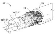
- FIG. 3is a perspective, partially cut-away view of a composite communications cable 100 according to embodiments of the present invention.
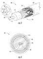
- FIG. 4is a transverse cross-sectional view of the composite communications cable 100 of FIG. 3 .
- the composite communications cable 100may extend in a “longitudinal” direction (which may also be referred to herein as an “axial” direction), and may have a generally round transverse cross-section.
- the cable 100includes a central conductor 112 that is surrounded by a dielectric spacer 114 .
- a metallic electrical shield 118which may comprise a plurality of braided shielding wires, surrounds the dielectric spacer 114 .
- a cable jacket 120surrounds the electrical shield 118 .
- the central conductor 112 , dielectric spacer 114 and electrical shield 118together comprise a coaxial transmission component 110 of composite cable 100 .
- the central conductor 112may comprise, for example, a copper or copper alloy wire of suitable gauge (e.g., 18 gauge) or a copper or copper alloy-plated aluminum or steel wire. Other conductive materials may also be used to form the central conductor.
- the dielectric spacer 114may be a any suitable insulative material including, for example, polytetrafluoroethylene (“PTFE”) or polyethylene.
- PTFEpolytetrafluoroethylene
- the dielectric constant of the dielectric spacer 114may be selected in view of, for example, the radii of the central conductor 112 and the electrical shield 118 to provide a characteristic impedance of 75 ohms.
- the dielectric spacer 114may be applied as a foam that cures to form a solid that surrounds the central conductor 112 .
- the electrical shield 118may comprise, for example, braided copper wire.
- a conductive tape(not shown) may be bonded to an outside surface of the dielectric spacer 114 , and one or more electrical shielding tapes (not shown) may surround the electrical shield 118 .
- the composite communications cable 100further includes a fiber optic transmission component 130 .
- this fiber optic transmission component 130comprises a non-buffered optical fiber 132 (which is also sometimes referred to as a “bare” optical fiber) that is positioned just outside the central conductor 112 .
- the optical fiber 132includes a core 134 and a surrounding cladding 136 .
- the core and cladding 134 , 136may be constructed in any suitable manner.
- each of the core 134 and cladding 136may include one or more concentric segments or layers, may be doped, etc.
- the core and cladding 134 , 136may be formed of any suitable materials and using any suitable methods.
- the core and cladding 134 , 136may comprise a glass core and cladding 134 , 136 . In other embodiments, the core and cladding 134 , 136 may comprise a plastic core and cladding 134 , 136 . Other suitable materials may also be used to form the core and/or cladding 134 , 136 .
- the non-buffered optical fiber 132further includes a coating layer 138 that surrounds the cladding 136 .
- the coating layer 138provides environmental protection for the core 134 and cladding 136 and may comprise, for example, a polymer layer.
- the coating layer 138consists of a single coating layer; however, multiple concentric layers may be applied to form the overall coating 138 .
- the coating layer 138may comprise an ultra-violet light-cured acrylate.
- the overall diameter of the optical fiber 132may be in the range of from about 235 to about 265 ⁇ m.
- the thickness of the coating layer 138is no greater than about 70.5 ⁇ m.
- the diameter of the core 134is between about 6 and about 64 ⁇ m and the thickness of the cladding 136 is between about 115 and about 135 ⁇ m.
- the optical fiber 132may extend parallel to the central conductor 112 and may be in direct contact with the central conductor 112 .
- the coaxial transmission component 110 and the fiber optic transmission component 130may both be encased within a protective jacket 120 .
- the jacket 120may be formed of any suitable material such as a polymeric material. According to some embodiments, the jacket 120 is formed of a thermoplastic polymer. Suitable polymeric materials may include, without limitation, PVC, PVDF or FRPE. The jacket 120 may be molded or extruded over the outer conductor 118 of the coaxial cable component 110 . Suitable apparatus and methods for forming the composite communications cable 100 will be apparent to those of skill in the art.
- the optical fiber 132will have a dielectric constant that is different than the dielectric constant of the dielectric spacer 114 . If only one (or a few) optical fibers 132 are included in the cable 100 , then the dielectric constant for the portion of the coaxial transmission component that includes the embedded optical fiber(s) will typically be different than the dielectric constant that will provide a 75 ohm characteristic impedance due to the inclusion of the optical fiber 132 having the different dielectric constant. Test results on one example embodiment that included an optical component that consisted of a single non-buffered optical fiber have shown that this deviation from an ideal characteristic impedance can result in an additional loss of about 3 dB per 100 feet of cable for a 1 GHz communications signal.
- this attenuation lossmay be reduced by using a plastic optical fiber instead of a glass optical fiber that has a dielectric constant that is more closely matched to the dielectric constant of the dielectric spacer 114 .
- the dielectric constant for state of the art coaxial cable dielectric spacersmay be about 1.25
- glass optical fibersmay have a dielectric constant of for example, about 3.8
- plastic core optical fibersmay have a dielectric constant of, for example, about 2.4-3.0, which is significantly closer to the dielectric constant of the dielectric spacer.
- the dielectric constant of the optical fibermay be no more than 2.4 times the dielectric constant of the dielectric spacer.
- a plastic optic fiber 132may also be capable of withstanding increased bending related stresses and/or strains without damage.
- the stresses and strains that are applied to the optical fiber 132 when the composite communications cable 100 is bentare reduced. These stresses and strains may be calculated based on the overall geometry of the composite communications cable 100 .
- the stress that will be applied to the optical fiber 132 if the cable 100 is bent to a radius that is ten (10) times the cable outside diameter, or in this case 2.75 inches (which is the maximum coaxial cable bend radius specified in the relevant industry standards document)is 0.9 percent.
- Optical fibersare commercially available that may readily handle this stress level without breaking or being damaged.
- the stress that will be applied to the optical fiber 132 if the cable 100 is bent to a radius of 2.75 inchesis 3.26%, which is outside of the acceptable range.
- a composite communications cablethat has a central conductor 112 with a diameter of 1.0 millimeters (0.040 inches), an optical fiber 132 that has a core/cladding layer 134 / 136 with a diameter of 125 microns, an acrylate coating 138 having a thickness of 250 microns and a tight buffer layer having a thickness of 900 microns (such that the composite communications cable has an overall outer diameter of 7 millimeters), the stress that will be applied to the optical fiber 132 if the cable is bent to a radius of 2.75 inches is 3.26 percent.
- Optical fibersare also commercially available that will handle this stress level without breaking or being damaged.
- the optical fiber 132may be located in a position that will protect the optical fiber 132 from damage.
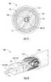
- FIG. 5is a transverse cross-sectional view of a composite communications cable 200 according to further embodiments of the present invention.
- the composite communications cable 200includes a coaxial transmission component 110 that may be identical to the coaxial transmission component 110 that is described above, and may likewise include a fiber optic transmission component 130 that may be identical to the fiber optic transmission component 130 that is described above. Accordingly, further description of components 110 and 130 will be omitted.
- the composite communications cable 200differs from the composite communications cable 100 in that in the composite communications cable 200 the fiber optic component 130 is spaced a small distance “x” from the central conductor 112 of the coaxial transmission component 110 as opposed to being directly adjacent to the central conductor 112 as is the case in the composite communications cable 100 of FIGS. 3 and 4 .
- the outside surface of the optical fiber 132may be no more than 50 microns from an outside surface of the central conductor 112 .
- the central axis of the optical fiber 132will be no more than 200 microns from an outer surface of the central conductor 112 .
- a release agent 140may be coated on the central conductor 112 and/or on the outer surface of the optical fiber 132 in order to facilitate separating the optical fiber 132 from the central conductor 112 and/or the dielectric spacer 114 in the event that the composite communications cable 200 is later used as a fiber optic cable instead of as a coaxial cable.
- This release agent 140may, in some embodiments, fill some or all of the space labeled “x” shown in FIG. 5 that exists between the optical fiber 132 and the central conductor 112 .
- a portion of the dielectric spacer 114may be positioned between the outer surface of the central conductor 112 and the optical fiber 132 .
- Other configurationsare also possible.
- FIG. 6is a perspective, partially cut-away view of a composite communications cable 300 according to still further embodiments of the present invention that includes a helically wound optical fiber transmission component 130 ′.
- the composite communications cable 300includes a coaxial transmission component 110 that may be identical to the coaxial transmission component 110 of the composite communications cable 100 that is described above with reference to FIGS. 3-4 .
- the composite communications cable 300further includes a fiber optic transmission component 130 ′ that includes a non-buffered optical fiber 132 ′.
- the non-buffered optical fiber 132 ′may be identical to the non-buffered optical fiber 132 of composite communications cable 100 , except that the optical fiber 132 ′ is helically wound about the central conductor 112 .
- Such a helical windingmay better balance the composite communications cable 300 and, to the extent that the optical fiber 132 ′ does not adhere to the dielectric spacer 114 or the central conductor 112 , may also allow more relative movement between the optical fiber 132 ′ and the remaining components of composite communications cable 300 , which facilitate reducing stresses and strains on the optical fiber 132 ′.
- the optical fiber 132 ′is wound helically in the same direction about the central conductor 112 for the entire length of the cable 300 .
- the optical fiber 132 ′may be wound helically about the central conductor 112 in a first direction for a first segment of the cable 300 and then may be wound helically about the central conductor 112 in a second (opposite) direction for another segment of the cable 300 (i.e., the optical fiber 132 ′ includes both clockwise helically wound sections and counterclockwise helically wound sections).
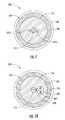
- FIG. 7is a perspective, partially cut-away view of a composite communications cable 400 according to embodiments of the present invention that includes a second optical fiber.
- the composite communications cable 400includes a coaxial transmission component 110 that may be identical to the coaxial transmission component 110 of the composite communications cable 100 that is described above with reference to FIGS. 3-4 .
- the fiber optic component 130 ′ of the composite communications cable 400includes both an optical fiber 132 - 1 and a second optical fiber 132 - 2 .
- the optical fibers 132 - 1 and 132 - 2may be identical to each other and may, for example, be implemented using the non-buffered optical fibers 132 that are described above. In other embodiments, the optical fibers 132 - 1 and 132 - 2 may be different from each other.
- the optical fibers 132 - 1 and 132 - 2may be positioned on opposite sides of the central conductor 112 , although other positions are also possible.
- FIG. 7illustrates a composite communications cable 400 that includes two optical fibers 132 - 1 and 132 - 2 , it will be appreciated that in other embodiments more than two optical fibers may be provided. It will also be appreciated that the composite cables 200 and 300 discussed above may be modified to include more than one optical fiber 132 .
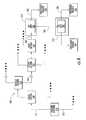
- FIG. 8is a simplified, schematic block diagram of a cable television network 500 according to embodiments of the present invention.
- the cable television network 500includes headend facilities 510 where signals (e.g., broadcast and other signals) from various sources, such as transmissions from satellites, microwave, fiber optic and other sources, are gathered and processed for transmission over the cable television network 500 . These signals are distributed via a main or “trunk” network 515 to trunk stations 520 . The signals may be further distributed from each trunk station 520 to a plurality of district sections 530 , where the signals are typically amplified by amplification units 540 . Each district section 530 may feed a plurality of feeder sections 550 . In many cable television networks, the signals that are passed between the headend facilities 510 and subscriber premises may be passed as optical signals over fiber optic cables through the trunk stations 520 , the district sections 530 and the feeder sections 550 .
- signalse.g., broadcast and other signals
- Each feeder section 550may feed a plurality of drop sections 560 .
- optical network interface unitsmay be provided in the drop sections 560 that convert downstream optical signals from the headend facilities 510 into electrical RF signals and that convert upstream RF signals from the subscriber premises into optical signals.
- Coaxial “drop” cables 565are connected to the output of each drop section 560 and are routed through neighborhoods and the like, and a plurality of distribution and amplification systems 570 are provided that connect individual subscriber premises 590 to the cable television network 500 .
- each distribution and amplification system 570includes a tap unit 580 that may provide connections to one or more subscriber premises 590 .
- the tap units 580are located outside near the subscriber premises 590 (i.e., on the outside of a building, in a cable box near the street, etc.). Drop cables 585 are provided that connect each subscriber premise 590 to a tap port on one of the tap units 580 .
- the drop cables 565may be composite communications cables according to embodiments of the present invention.
- Coaxial connectorsmay be installed on each end of each drop cable 565 in order to allow the network side of each drop cable 565 to be connected to, for example, a coaxial connector provided on network equipment at the drop sections 560 , and to allow the subscriber side of each drop cable 565 to be connected to, for example, a coaxial connector port on a tap unit 580 .
- the drop cables 585 that extend from the tap units 580 to the individual subscriber premises 590may comprise composite communications cables according to embodiments of the present invention.
- Coaxial connectorsmay also be installed on each end of each drop cable 585 in order to allow the network side of each drop cable 585 to be connected to, for example, a coaxial connector tap port on a tap unit 580 , and to allow the subscriber side of each drop cable 585 to be connected to, for example, a coaxial connector RF input port on a signal amplifier or other unit at a subscriber premise 590 .
- the cable television network 500may then be operated in a conventional manner as a hybrid fiber-coaxial network with RF (coaxial) connections from, for example, the drop sections 560 to the subscriber premises 590 using the coaxial transmission component of the composite communications cable.
- the cable television network 500implements, for example, the drop cables 565 and 585 using composite communications cables according to embodiments of the present invention, it may be more easily upgraded at a later date to provide fiber-to-the-home functionality.
- a slack loopthat includes perhaps six to eighteen inches of excess cable may be provided on each end of the drop cables 565 and 585 during the installation process.
- the coaxial connectorsthat are provided on each end of the cables 565 and 585 to be disconnected from the above-mentioned coaxial connector ports.
- the coaxial connectorsmay then be removed from each end of the drop cables 565 , 585 , and end portions of the cable jacket, electrical shield and dielectric spacer may be stripped back or removed from each end of the drop cables 565 , 585 to expose the fiber optic communication element of these cables.
- the central conductor of the drop cablesmay also be removed.
- the provision of the above-mentioned slack loopsmay provide excess cabling that allows a portion of each end of the drop cables 565 , 585 to be removed or stripped back.
- a plug terminationmay be installed on each end of the drop cables 565 , 585 .
- the plug terminationmay receive, for example, the fiber optic component, and may also receive the cable jacket and/or the central conductor.
- the plug terminationmay include, for example, at least one ferrule.
- Each optical fiber of the fiber optic component of the drop cables 565 , 585may be inserted in a respective ferrule of the plug termination to convert the drop cables 565 , 585 into fiber optic patch cords 565 ′, 585 ′.
- a network interface unitmay be installed at the subscriber premises 590 , and the network equipment in the drop sections 560 and the tap units 580 may be replaced with corresponding fiber optic equipment.
- the fiber optic patch cords 565 ′, 585 ′may be connected to the above-described fiber optic apparatus to provide a fiber optic connection all the way from the head end facilities 510 to the subscriber premises 590 . This fiber optic connection may support substantially more bandwidth than the coaxial cable connections that were originally provided to the subscriber premises 590 .
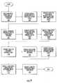
- FIG. 9is a flow chart that illustrates one example of these methods.
- a composite coaxial-fiber drop cablesuch as the cables according to embodiments of the present invention is run between a subscriber premise and a distribution and amplification unit of the network (block 600 ).
- the cablemay be pre-cut or cut at the time of deployment to have sufficient length to include a slack loop at or near at least one end of the cable.
- a coaxial connectoris mounted on at least one end of the composite cable (block 605 ).
- the composite cablemay then be connected to apparatus at both the subscriber premise and the distribution and amplification unit to provide an electrical RF communications path between the distribution and amplification (“D&A”) unit and the subscriber premise (block 610 ).
- D&Adistribution and amplification
- a first slack loopmay be formed in the composite cable at or near the subscriber premise and/or a second slack loop may be formed in the composite cable at or near the distribution and amplification unit.
- the cable television networkmay be upgraded to provide fiber-to-the-home functionality.
- a network interface unitmay be installed at or near the subscriber premise and connected to equipment and/or cabling in the subscriber premises (block 615 ).
- a first coaxial connectormay be removed from the end of the composite cable that connects to the subscriber premise, and various of the coaxial transmission components of this end of the composite cable may be stripped back to expose a segment of the fiber optic transmission component of the composite cable (block 620 ).
- a fiber optic terminationmay then be terminated onto the fiber optic transmission component (block 625 ), and the composite cable may then be connected to a fiber optic port on the network interface unit (block 630 ).
- Fiber optic distribution equipment(which may include amplification, if appropriate) may be installed in place of existing RF distribution and amplification equipment and connected to fiber optic connections of the cable television network (block 635 ).
- a second coaxial connectormay be removed from the end of the composite cable that connects to the distribution and amplification equipment, and various of the coaxial transmission components of this end of the composite cable may be stripped back to expose a segment of the fiber optic transmission component of the composite cable (block 640 ).
- a fiber optic terminationmay then be terminated onto the fiber optic transmission component (block 645 ), and the composite cable may then be connected to a fiber optic port on the fiber optic distribution equipment (block 650 ). In this fashion, the cable television network 500 may be upgraded to implement fiber-to-the-home functionality without any need to install new drop cables.
- the fiber optic distribution equipmentthat is discussed with respect to block 650 of FIG. 9 may be a network interface unit or a similar device that converts optical signals to electrical signals and/or splits the signal for distribution throughout a subscriber premise.
- the coaxial connectormay be removed from the composite communications cable 100 , and a tool which only cuts through the outer jacket 120 , outer conductor 118 and a portion of the dielectric spacer 114 may then be used to access the optical fiber 132 without damaging the optical fiber 132 .
- this toolmay be designed to cut the dielectric spacer 114 to a depth such that it is only “scored,” and the scored section of the dielectric spacer 114 may then be manually manipulated to break it off without damaging the optical fiber 132 . Steps may also be taken to protect the optical fiber 132 from the center conductor 112 such as, for example, removing the portion of the center conductor 112 that extends beyond the dielectric spacer 114 , bending this portion of the center conductor 112 away from the optical fiber 132 or coating the exposed portion of the center conductor 112 to eliminate any possible mechanical degradation of the optical fiber 132 by the center conductor 112 .
- the composite communications cable 100may be routed into the interior of the network interface unit (e.g., through a grommet in a sidewall of the unit).
- a strain relief mechanismmay be provided in the interior of the network interface unit, and the composite communications cable 100 may be connected to the strain relief mechanism.
- the exposed optical fiber 132may then be placed within a furcation tube that protects the optical fiber 132 .
- a pigtail connectormay be provided that comprises, for example a tightly-buffered optical fiber that has a male connector mounted on one end thereof.
- a fusion splicermay then be used to align the exposed end of the optical fiber 132 to the exposed end of the tightly-buffered optical fiber on the pigtail connector and to then fuse the two together.
- the male connector on the pigtailmay then be plugged into a female optical fiber connector port that is within the network interface unit to optically connect the optical fiber 132 to optical equipment within the network interface unit.
- a similar processmay be used to convert the other end of the composite communications cable 100 (i.e., the end that was previously connected to, for example, a tap unit) from use as a coaxial cable to a use as a fiber optic cable.
- the optical equipment that the composite communications cable 100will be connected to at the tap unit will comprise passive equipment as opposed to the network interface unit that is provided at the subscriber premise.
- FIG. 10is a transverse, cross-sectional view of a composite communications cable 600 according to still further embodiments of the present invention.
- the composite communications cable 600includes a coaxial transmission component 110 that may be identical to the coaxial transmission component 110 of the composite communications cable 100 that is described above with reference to FIGS. 3-4 .
- the composite communications cable 600further includes a fiber optic transmission component 630 that includes a tightly-buffered optical fiber 632 .
- the tightly-buffered optical fiber 632has a central core, a cladding layer concentrically surrounding the core, a polymer layer concentrically surrounding the cladding layer, and an outer plastic layer 637 concentrically surrounding the polymer layer and joined to the polymer layer.
- the tightly-buffered optical fiber 632is larger than the non-buffered optical fibers depicted in the embodiments of the present invention discussed above.
- a central axis of the optical fiber 632may be within 450 microns of an outer surface of the central conductor 112 .
- An outer surface of the tightly-buffered optical fiber 632may be within 50 microns of the outer surface of the central conductor 112 and, in some embodiments, may directly contact an outside surface of the central conductor.
- the core of the tightly-buffered optical fiber 632may be, for example, a glass core or a plastic core.
- This inventionis directed, in part, to composite communications cables.
- the term “longitudinal” and derivatives thereofrefer to the lengthwise direction defined by the central axis of the cable when the cable is pulled taunt in a straight line.
- the terms “transverse plane” and “transverse cross-section”refer to a plane and cross-section, respectively, that are taken normal to the longitudinal direction.
Landscapes
- Physics & Mathematics (AREA)
- General Physics & Mathematics (AREA)
- Optics & Photonics (AREA)
- Communication Cables (AREA)
Abstract
Description
Claims (21)
Priority Applications (3)
| Application Number | Priority Date | Filing Date | Title |
|---|---|---|---|
| US13/523,185US8917964B2 (en) | 2012-06-14 | 2012-06-14 | Composite communications cables having a fiber optic component located adjacent an outer surface of the central conductor of a coaxial cable component and related methods |
| CA2817600ACA2817600A1 (en) | 2012-06-14 | 2013-06-04 | Composite communications cables having a fiber optic component located adjacent an outer surface of the central conductor of a coaxial cable component and related methods |
| MX2013006772AMX2013006772A (en) | 2012-06-14 | 2013-06-13 | Composite communications cables having a fiber optic component located adjacent an outer surface of the central conductor of a coaxial cable component and related methods. |
Applications Claiming Priority (1)
| Application Number | Priority Date | Filing Date | Title |
|---|---|---|---|
| US13/523,185US8917964B2 (en) | 2012-06-14 | 2012-06-14 | Composite communications cables having a fiber optic component located adjacent an outer surface of the central conductor of a coaxial cable component and related methods |
Publications (2)
| Publication Number | Publication Date |
|---|---|
| US20130336623A1 US20130336623A1 (en) | 2013-12-19 |
| US8917964B2true US8917964B2 (en) | 2014-12-23 |
Family
ID=49753592
Family Applications (1)
| Application Number | Title | Priority Date | Filing Date |
|---|---|---|---|
| US13/523,185Expired - Fee RelatedUS8917964B2 (en) | 2012-06-14 | 2012-06-14 | Composite communications cables having a fiber optic component located adjacent an outer surface of the central conductor of a coaxial cable component and related methods |
Country Status (3)
| Country | Link |
|---|---|
| US (1) | US8917964B2 (en) |
| CA (1) | CA2817600A1 (en) |
| MX (1) | MX2013006772A (en) |
Cited By (169)
| Publication number | Priority date | Publication date | Assignee | Title |
|---|---|---|---|---|
| US9119127B1 (en) | 2012-12-05 | 2015-08-25 | At&T Intellectual Property I, Lp | Backhaul link for distributed antenna system |
| US9154966B2 (en) | 2013-11-06 | 2015-10-06 | At&T Intellectual Property I, Lp | Surface-wave communications and methods thereof |
| US9209902B2 (en) | 2013-12-10 | 2015-12-08 | At&T Intellectual Property I, L.P. | Quasi-optical coupler |
| US9312919B1 (en) | 2014-10-21 | 2016-04-12 | At&T Intellectual Property I, Lp | Transmission device with impairment compensation and methods for use therewith |
| US9461706B1 (en) | 2015-07-31 | 2016-10-04 | At&T Intellectual Property I, Lp | Method and apparatus for exchanging communication signals |
| US9490869B1 (en) | 2015-05-14 | 2016-11-08 | At&T Intellectual Property I, L.P. | Transmission medium having multiple cores and methods for use therewith |
| US9503189B2 (en) | 2014-10-10 | 2016-11-22 | At&T Intellectual Property I, L.P. | Method and apparatus for arranging communication sessions in a communication system |
| US9509415B1 (en) | 2015-06-25 | 2016-11-29 | At&T Intellectual Property I, L.P. | Methods and apparatus for inducing a fundamental wave mode on a transmission medium |
| US9520945B2 (en) | 2014-10-21 | 2016-12-13 | At&T Intellectual Property I, L.P. | Apparatus for providing communication services and methods thereof |
| US9525524B2 (en) | 2013-05-31 | 2016-12-20 | At&T Intellectual Property I, L.P. | Remote distributed antenna system |
| US9525210B2 (en) | 2014-10-21 | 2016-12-20 | At&T Intellectual Property I, L.P. | Guided-wave transmission device with non-fundamental mode propagation and methods for use therewith |
| US9531427B2 (en) | 2014-11-20 | 2016-12-27 | At&T Intellectual Property I, L.P. | Transmission device with mode division multiplexing and methods for use therewith |
| US9564947B2 (en) | 2014-10-21 | 2017-02-07 | At&T Intellectual Property I, L.P. | Guided-wave transmission device with diversity and methods for use therewith |
| US9577307B2 (en) | 2014-10-21 | 2017-02-21 | At&T Intellectual Property I, L.P. | Guided-wave transmission device and methods for use therewith |
| US9608740B2 (en) | 2015-07-15 | 2017-03-28 | At&T Intellectual Property I, L.P. | Method and apparatus for launching a wave mode that mitigates interference |
| US9608692B2 (en) | 2015-06-11 | 2017-03-28 | At&T Intellectual Property I, L.P. | Repeater and methods for use therewith |
| US9615269B2 (en) | 2014-10-02 | 2017-04-04 | At&T Intellectual Property I, L.P. | Method and apparatus that provides fault tolerance in a communication network |
| US9628116B2 (en) | 2015-07-14 | 2017-04-18 | At&T Intellectual Property I, L.P. | Apparatus and methods for transmitting wireless signals |
| US9628854B2 (en) | 2014-09-29 | 2017-04-18 | At&T Intellectual Property I, L.P. | Method and apparatus for distributing content in a communication network |
| US9640850B2 (en) | 2015-06-25 | 2017-05-02 | At&T Intellectual Property I, L.P. | Methods and apparatus for inducing a non-fundamental wave mode on a transmission medium |
| US9653770B2 (en) | 2014-10-21 | 2017-05-16 | At&T Intellectual Property I, L.P. | Guided wave coupler, coupling module and methods for use therewith |
| US9654173B2 (en) | 2014-11-20 | 2017-05-16 | At&T Intellectual Property I, L.P. | Apparatus for powering a communication device and methods thereof |
| US9667317B2 (en) | 2015-06-15 | 2017-05-30 | At&T Intellectual Property I, L.P. | Method and apparatus for providing security using network traffic adjustments |
| US9680670B2 (en) | 2014-11-20 | 2017-06-13 | At&T Intellectual Property I, L.P. | Transmission device with channel equalization and control and methods for use therewith |
| US9685992B2 (en) | 2014-10-03 | 2017-06-20 | At&T Intellectual Property I, L.P. | Circuit panel network and methods thereof |
| US9692101B2 (en) | 2014-08-26 | 2017-06-27 | At&T Intellectual Property I, L.P. | Guided wave couplers for coupling electromagnetic waves between a waveguide surface and a surface of a wire |
| US9705561B2 (en) | 2015-04-24 | 2017-07-11 | At&T Intellectual Property I, L.P. | Directional coupling device and methods for use therewith |
| US9705571B2 (en) | 2015-09-16 | 2017-07-11 | At&T Intellectual Property I, L.P. | Method and apparatus for use with a radio distributed antenna system |
| US9722318B2 (en) | 2015-07-14 | 2017-08-01 | At&T Intellectual Property I, L.P. | Method and apparatus for coupling an antenna to a device |
| US9729197B2 (en) | 2015-10-01 | 2017-08-08 | At&T Intellectual Property I, L.P. | Method and apparatus for communicating network management traffic over a network |
| US9735833B2 (en) | 2015-07-31 | 2017-08-15 | At&T Intellectual Property I, L.P. | Method and apparatus for communications management in a neighborhood network |
| US9742462B2 (en) | 2014-12-04 | 2017-08-22 | At&T Intellectual Property I, L.P. | Transmission medium and communication interfaces and methods for use therewith |
| US9749013B2 (en) | 2015-03-17 | 2017-08-29 | At&T Intellectual Property I, L.P. | Method and apparatus for reducing attenuation of electromagnetic waves guided by a transmission medium |
| US9749053B2 (en) | 2015-07-23 | 2017-08-29 | At&T Intellectual Property I, L.P. | Node device, repeater and methods for use therewith |
| US9748626B2 (en) | 2015-05-14 | 2017-08-29 | At&T Intellectual Property I, L.P. | Plurality of cables having different cross-sectional shapes which are bundled together to form a transmission medium |
| US9755697B2 (en) | 2014-09-15 | 2017-09-05 | At&T Intellectual Property I, L.P. | Method and apparatus for sensing a condition in a transmission medium of electromagnetic waves |
| US9762289B2 (en) | 2014-10-14 | 2017-09-12 | At&T Intellectual Property I, L.P. | Method and apparatus for transmitting or receiving signals in a transportation system |
| US9769128B2 (en) | 2015-09-28 | 2017-09-19 | At&T Intellectual Property I, L.P. | Method and apparatus for encryption of communications over a network |
| US9769020B2 (en) | 2014-10-21 | 2017-09-19 | At&T Intellectual Property I, L.P. | Method and apparatus for responding to events affecting communications in a communication network |
| US9780834B2 (en) | 2014-10-21 | 2017-10-03 | At&T Intellectual Property I, L.P. | Method and apparatus for transmitting electromagnetic waves |
| US9793951B2 (en) | 2015-07-15 | 2017-10-17 | At&T Intellectual Property I, L.P. | Method and apparatus for launching a wave mode that mitigates interference |
| US9793955B2 (en) | 2015-04-24 | 2017-10-17 | At&T Intellectual Property I, Lp | Passive electrical coupling device and methods for use therewith |
| US9793954B2 (en) | 2015-04-28 | 2017-10-17 | At&T Intellectual Property I, L.P. | Magnetic coupling device and methods for use therewith |
| US9800327B2 (en) | 2014-11-20 | 2017-10-24 | At&T Intellectual Property I, L.P. | Apparatus for controlling operations of a communication device and methods thereof |
| US9820146B2 (en) | 2015-06-12 | 2017-11-14 | At&T Intellectual Property I, L.P. | Method and apparatus for authentication and identity management of communicating devices |
| US9838896B1 (en) | 2016-12-09 | 2017-12-05 | At&T Intellectual Property I, L.P. | Method and apparatus for assessing network coverage |
| US9836957B2 (en) | 2015-07-14 | 2017-12-05 | At&T Intellectual Property I, L.P. | Method and apparatus for communicating with premises equipment |
| US9847566B2 (en) | 2015-07-14 | 2017-12-19 | At&T Intellectual Property I, L.P. | Method and apparatus for adjusting a field of a signal to mitigate interference |
| US9847850B2 (en) | 2014-10-14 | 2017-12-19 | At&T Intellectual Property I, L.P. | Method and apparatus for adjusting a mode of communication in a communication network |
| US9853342B2 (en) | 2015-07-14 | 2017-12-26 | At&T Intellectual Property I, L.P. | Dielectric transmission medium connector and methods for use therewith |
| US9860075B1 (en) | 2016-08-26 | 2018-01-02 | At&T Intellectual Property I, L.P. | Method and communication node for broadband distribution |
| US9866309B2 (en) | 2015-06-03 | 2018-01-09 | At&T Intellectual Property I, Lp | Host node device and methods for use therewith |
| US9865911B2 (en) | 2015-06-25 | 2018-01-09 | At&T Intellectual Property I, L.P. | Waveguide system for slot radiating first electromagnetic waves that are combined into a non-fundamental wave mode second electromagnetic wave on a transmission medium |
| US9871282B2 (en) | 2015-05-14 | 2018-01-16 | At&T Intellectual Property I, L.P. | At least one transmission medium having a dielectric surface that is covered at least in part by a second dielectric |
| US9871283B2 (en) | 2015-07-23 | 2018-01-16 | At&T Intellectual Property I, Lp | Transmission medium having a dielectric core comprised of plural members connected by a ball and socket configuration |
| US9876571B2 (en) | 2015-02-20 | 2018-01-23 | At&T Intellectual Property I, Lp | Guided-wave transmission device with non-fundamental mode propagation and methods for use therewith |
| US9876605B1 (en) | 2016-10-21 | 2018-01-23 | At&T Intellectual Property I, L.P. | Launcher and coupling system to support desired guided wave mode |
| US9876264B2 (en) | 2015-10-02 | 2018-01-23 | At&T Intellectual Property I, Lp | Communication system, guided wave switch and methods for use therewith |
| US9882277B2 (en) | 2015-10-02 | 2018-01-30 | At&T Intellectual Property I, Lp | Communication device and antenna assembly with actuated gimbal mount |
| US9882257B2 (en) | 2015-07-14 | 2018-01-30 | At&T Intellectual Property I, L.P. | Method and apparatus for launching a wave mode that mitigates interference |
| US9893795B1 (en) | 2016-12-07 | 2018-02-13 | At&T Intellectual Property I, Lp | Method and repeater for broadband distribution |
| US9904535B2 (en) | 2015-09-14 | 2018-02-27 | At&T Intellectual Property I, L.P. | Method and apparatus for distributing software |
| US9906269B2 (en) | 2014-09-17 | 2018-02-27 | At&T Intellectual Property I, L.P. | Monitoring and mitigating conditions in a communication network |
| US9913139B2 (en) | 2015-06-09 | 2018-03-06 | At&T Intellectual Property I, L.P. | Signal fingerprinting for authentication of communicating devices |
| US9912381B2 (en) | 2015-06-03 | 2018-03-06 | At&T Intellectual Property I, Lp | Network termination and methods for use therewith |
| US9912027B2 (en) | 2015-07-23 | 2018-03-06 | At&T Intellectual Property I, L.P. | Method and apparatus for exchanging communication signals |
| US9911020B1 (en) | 2016-12-08 | 2018-03-06 | At&T Intellectual Property I, L.P. | Method and apparatus for tracking via a radio frequency identification device |
| US9912419B1 (en) | 2016-08-24 | 2018-03-06 | At&T Intellectual Property I, L.P. | Method and apparatus for managing a fault in a distributed antenna system |
| US9917341B2 (en) | 2015-05-27 | 2018-03-13 | At&T Intellectual Property I, L.P. | Apparatus and method for launching electromagnetic waves and for modifying radial dimensions of the propagating electromagnetic waves |
| US9927517B1 (en) | 2016-12-06 | 2018-03-27 | At&T Intellectual Property I, L.P. | Apparatus and methods for sensing rainfall |
| US9948354B2 (en) | 2015-04-28 | 2018-04-17 | At&T Intellectual Property I, L.P. | Magnetic coupling device with reflective plate and methods for use therewith |
| US9948333B2 (en) | 2015-07-23 | 2018-04-17 | At&T Intellectual Property I, L.P. | Method and apparatus for wireless communications to mitigate interference |
| US9954287B2 (en) | 2014-11-20 | 2018-04-24 | At&T Intellectual Property I, L.P. | Apparatus for converting wireless signals and electromagnetic waves and methods thereof |
| US9967173B2 (en) | 2015-07-31 | 2018-05-08 | At&T Intellectual Property I, L.P. | Method and apparatus for authentication and identity management of communicating devices |
| US9973940B1 (en) | 2017-02-27 | 2018-05-15 | At&T Intellectual Property I, L.P. | Apparatus and methods for dynamic impedance matching of a guided wave launcher |
| US9991580B2 (en) | 2016-10-21 | 2018-06-05 | At&T Intellectual Property I, L.P. | Launcher and coupling system for guided wave mode cancellation |
| US9997819B2 (en) | 2015-06-09 | 2018-06-12 | At&T Intellectual Property I, L.P. | Transmission medium and method for facilitating propagation of electromagnetic waves via a core |
| US9999038B2 (en) | 2013-05-31 | 2018-06-12 | At&T Intellectual Property I, L.P. | Remote distributed antenna system |
| US9998870B1 (en) | 2016-12-08 | 2018-06-12 | At&T Intellectual Property I, L.P. | Method and apparatus for proximity sensing |
| US10009063B2 (en) | 2015-09-16 | 2018-06-26 | At&T Intellectual Property I, L.P. | Method and apparatus for use with a radio distributed antenna system having an out-of-band reference signal |
| US10009067B2 (en) | 2014-12-04 | 2018-06-26 | At&T Intellectual Property I, L.P. | Method and apparatus for configuring a communication interface |
| US10009901B2 (en) | 2015-09-16 | 2018-06-26 | At&T Intellectual Property I, L.P. | Method, apparatus, and computer-readable storage medium for managing utilization of wireless resources between base stations |
| US10009065B2 (en) | 2012-12-05 | 2018-06-26 | At&T Intellectual Property I, L.P. | Backhaul link for distributed antenna system |
| US10020844B2 (en) | 2016-12-06 | 2018-07-10 | T&T Intellectual Property I, L.P. | Method and apparatus for broadcast communication via guided waves |
| US10020587B2 (en) | 2015-07-31 | 2018-07-10 | At&T Intellectual Property I, L.P. | Radial antenna and methods for use therewith |
| US10027397B2 (en) | 2016-12-07 | 2018-07-17 | At&T Intellectual Property I, L.P. | Distributed antenna system and methods for use therewith |
| US10033108B2 (en) | 2015-07-14 | 2018-07-24 | At&T Intellectual Property I, L.P. | Apparatus and methods for generating an electromagnetic wave having a wave mode that mitigates interference |
| US10033107B2 (en) | 2015-07-14 | 2018-07-24 | At&T Intellectual Property I, L.P. | Method and apparatus for coupling an antenna to a device |
| US10044409B2 (en) | 2015-07-14 | 2018-08-07 | At&T Intellectual Property I, L.P. | Transmission medium and methods for use therewith |
| US10051483B2 (en) | 2015-10-16 | 2018-08-14 | At&T Intellectual Property I, L.P. | Method and apparatus for directing wireless signals |
| US10051629B2 (en) | 2015-09-16 | 2018-08-14 | At&T Intellectual Property I, L.P. | Method and apparatus for use with a radio distributed antenna system having an in-band reference signal |
| US10069535B2 (en) | 2016-12-08 | 2018-09-04 | At&T Intellectual Property I, L.P. | Apparatus and methods for launching electromagnetic waves having a certain electric field structure |
| US10074890B2 (en) | 2015-10-02 | 2018-09-11 | At&T Intellectual Property I, L.P. | Communication device and antenna with integrated light assembly |
| US10079661B2 (en) | 2015-09-16 | 2018-09-18 | At&T Intellectual Property I, L.P. | Method and apparatus for use with a radio distributed antenna system having a clock reference |
| US10090594B2 (en) | 2016-11-23 | 2018-10-02 | At&T Intellectual Property I, L.P. | Antenna system having structural configurations for assembly |
| US10090606B2 (en) | 2015-07-15 | 2018-10-02 | At&T Intellectual Property I, L.P. | Antenna system with dielectric array and methods for use therewith |
| US10103422B2 (en) | 2016-12-08 | 2018-10-16 | At&T Intellectual Property I, L.P. | Method and apparatus for mounting network devices |
| US10103801B2 (en) | 2015-06-03 | 2018-10-16 | At&T Intellectual Property I, L.P. | Host node device and methods for use therewith |
| US10135147B2 (en) | 2016-10-18 | 2018-11-20 | At&T Intellectual Property I, L.P. | Apparatus and methods for launching guided waves via an antenna |
| US10135145B2 (en) | 2016-12-06 | 2018-11-20 | At&T Intellectual Property I, L.P. | Apparatus and methods for generating an electromagnetic wave along a transmission medium |
| US10135146B2 (en) | 2016-10-18 | 2018-11-20 | At&T Intellectual Property I, L.P. | Apparatus and methods for launching guided waves via circuits |
| US10136434B2 (en) | 2015-09-16 | 2018-11-20 | At&T Intellectual Property I, L.P. | Method and apparatus for use with a radio distributed antenna system having an ultra-wideband control channel |
| US10142086B2 (en) | 2015-06-11 | 2018-11-27 | At&T Intellectual Property I, L.P. | Repeater and methods for use therewith |
| US10139820B2 (en) | 2016-12-07 | 2018-11-27 | At&T Intellectual Property I, L.P. | Method and apparatus for deploying equipment of a communication system |
| US10144036B2 (en) | 2015-01-30 | 2018-12-04 | At&T Intellectual Property I, L.P. | Method and apparatus for mitigating interference affecting a propagation of electromagnetic waves guided by a transmission medium |
| US10148016B2 (en) | 2015-07-14 | 2018-12-04 | At&T Intellectual Property I, L.P. | Apparatus and methods for communicating utilizing an antenna array |
| US10154493B2 (en) | 2015-06-03 | 2018-12-11 | At&T Intellectual Property I, L.P. | Network termination and methods for use therewith |
| US10170840B2 (en) | 2015-07-14 | 2019-01-01 | At&T Intellectual Property I, L.P. | Apparatus and methods for sending or receiving electromagnetic signals |
| US10168695B2 (en) | 2016-12-07 | 2019-01-01 | At&T Intellectual Property I, L.P. | Method and apparatus for controlling an unmanned aircraft |
| US10178445B2 (en) | 2016-11-23 | 2019-01-08 | At&T Intellectual Property I, L.P. | Methods, devices, and systems for load balancing between a plurality of waveguides |
| US10205655B2 (en) | 2015-07-14 | 2019-02-12 | At&T Intellectual Property I, L.P. | Apparatus and methods for communicating utilizing an antenna array and multiple communication paths |
| US10224634B2 (en) | 2016-11-03 | 2019-03-05 | At&T Intellectual Property I, L.P. | Methods and apparatus for adjusting an operational characteristic of an antenna |
| US10225025B2 (en) | 2016-11-03 | 2019-03-05 | At&T Intellectual Property I, L.P. | Method and apparatus for detecting a fault in a communication system |
| US10243270B2 (en) | 2016-12-07 | 2019-03-26 | At&T Intellectual Property I, L.P. | Beam adaptive multi-feed dielectric antenna system and methods for use therewith |
| US10243784B2 (en) | 2014-11-20 | 2019-03-26 | At&T Intellectual Property I, L.P. | System for generating topology information and methods thereof |
| US10264586B2 (en) | 2016-12-09 | 2019-04-16 | At&T Mobility Ii Llc | Cloud-based packet controller and methods for use therewith |
| US10291311B2 (en) | 2016-09-09 | 2019-05-14 | At&T Intellectual Property I, L.P. | Method and apparatus for mitigating a fault in a distributed antenna system |
| US10291334B2 (en) | 2016-11-03 | 2019-05-14 | At&T Intellectual Property I, L.P. | System for detecting a fault in a communication system |
| US10298293B2 (en) | 2017-03-13 | 2019-05-21 | At&T Intellectual Property I, L.P. | Apparatus of communication utilizing wireless network devices |
| US10305190B2 (en) | 2016-12-01 | 2019-05-28 | At&T Intellectual Property I, L.P. | Reflecting dielectric antenna system and methods for use therewith |
| US10312567B2 (en) | 2016-10-26 | 2019-06-04 | At&T Intellectual Property I, L.P. | Launcher with planar strip antenna and methods for use therewith |
| US10320586B2 (en) | 2015-07-14 | 2019-06-11 | At&T Intellectual Property I, L.P. | Apparatus and methods for generating non-interfering electromagnetic waves on an insulated transmission medium |
| US10326689B2 (en) | 2016-12-08 | 2019-06-18 | At&T Intellectual Property I, L.P. | Method and system for providing alternative communication paths |
| US10326494B2 (en) | 2016-12-06 | 2019-06-18 | At&T Intellectual Property I, L.P. | Apparatus for measurement de-embedding and methods for use therewith |
| US10340600B2 (en) | 2016-10-18 | 2019-07-02 | At&T Intellectual Property I, L.P. | Apparatus and methods for launching guided waves via plural waveguide systems |
| US10341142B2 (en) | 2015-07-14 | 2019-07-02 | At&T Intellectual Property I, L.P. | Apparatus and methods for generating non-interfering electromagnetic waves on an uninsulated conductor |
| US10340983B2 (en) | 2016-12-09 | 2019-07-02 | At&T Intellectual Property I, L.P. | Method and apparatus for surveying remote sites via guided wave communications |
| US10340603B2 (en) | 2016-11-23 | 2019-07-02 | At&T Intellectual Property I, L.P. | Antenna system having shielded structural configurations for assembly |
| US10340573B2 (en) | 2016-10-26 | 2019-07-02 | At&T Intellectual Property I, L.P. | Launcher with cylindrical coupling device and methods for use therewith |
| US10340601B2 (en) | 2016-11-23 | 2019-07-02 | At&T Intellectual Property I, L.P. | Multi-antenna system and methods for use therewith |
| US10348391B2 (en) | 2015-06-03 | 2019-07-09 | At&T Intellectual Property I, L.P. | Client node device with frequency conversion and methods for use therewith |
| US10355367B2 (en) | 2015-10-16 | 2019-07-16 | At&T Intellectual Property I, L.P. | Antenna structure for exchanging wireless signals |
| US10359749B2 (en) | 2016-12-07 | 2019-07-23 | At&T Intellectual Property I, L.P. | Method and apparatus for utilities management via guided wave communication |
| US10361489B2 (en) | 2016-12-01 | 2019-07-23 | At&T Intellectual Property I, L.P. | Dielectric dish antenna system and methods for use therewith |
| US10374316B2 (en) | 2016-10-21 | 2019-08-06 | At&T Intellectual Property I, L.P. | System and dielectric antenna with non-uniform dielectric |
| US10382976B2 (en) | 2016-12-06 | 2019-08-13 | At&T Intellectual Property I, L.P. | Method and apparatus for managing wireless communications based on communication paths and network device positions |
| US10389029B2 (en) | 2016-12-07 | 2019-08-20 | At&T Intellectual Property I, L.P. | Multi-feed dielectric antenna system with core selection and methods for use therewith |
| US10389037B2 (en) | 2016-12-08 | 2019-08-20 | At&T Intellectual Property I, L.P. | Apparatus and methods for selecting sections of an antenna array and use therewith |
| US10396887B2 (en) | 2015-06-03 | 2019-08-27 | At&T Intellectual Property I, L.P. | Client node device and methods for use therewith |
| US10411920B2 (en) | 2014-11-20 | 2019-09-10 | At&T Intellectual Property I, L.P. | Methods and apparatus for inducing electromagnetic waves within pathways of a cable |
| US10411356B2 (en) | 2016-12-08 | 2019-09-10 | At&T Intellectual Property I, L.P. | Apparatus and methods for selectively targeting communication devices with an antenna array |
| US10439675B2 (en) | 2016-12-06 | 2019-10-08 | At&T Intellectual Property I, L.P. | Method and apparatus for repeating guided wave communication signals |
| US10446936B2 (en) | 2016-12-07 | 2019-10-15 | At&T Intellectual Property I, L.P. | Multi-feed dielectric antenna system and methods for use therewith |
| US10498044B2 (en) | 2016-11-03 | 2019-12-03 | At&T Intellectual Property I, L.P. | Apparatus for configuring a surface of an antenna |
| US10505252B2 (en) | 2014-11-20 | 2019-12-10 | At&T Intellectual Property I, L.P. | Communication system having a coupler for guiding electromagnetic waves through interstitial areas formed by a plurality of stranded uninsulated conductors and method of use |
| US10505248B2 (en) | 2014-11-20 | 2019-12-10 | At&T Intellectual Property I, L.P. | Communication cable having a plurality of uninsulated conductors forming interstitial areas for propagating electromagnetic waves therein and method of use |
| US10505249B2 (en) | 2014-11-20 | 2019-12-10 | At&T Intellectual Property I, L.P. | Communication system having a cable with a plurality of stranded uninsulated conductors forming interstitial areas for guiding electromagnetic waves therein and method of use |
| US10505250B2 (en) | 2014-11-20 | 2019-12-10 | At&T Intellectual Property I, L.P. | Communication system having a cable with a plurality of stranded uninsulated conductors forming interstitial areas for propagating guided wave modes therein and methods of use |
| US10516555B2 (en) | 2014-11-20 | 2019-12-24 | At&T Intellectual Property I, L.P. | Methods and apparatus for creating interstitial areas in a cable |
| US10530505B2 (en) | 2016-12-08 | 2020-01-07 | At&T Intellectual Property I, L.P. | Apparatus and methods for launching electromagnetic waves along a transmission medium |
| US10535928B2 (en) | 2016-11-23 | 2020-01-14 | At&T Intellectual Property I, L.P. | Antenna system and methods for use therewith |
| US10547348B2 (en) | 2016-12-07 | 2020-01-28 | At&T Intellectual Property I, L.P. | Method and apparatus for switching transmission mediums in a communication system |
| US10554454B2 (en) | 2014-11-20 | 2020-02-04 | At&T Intellectual Property I, L.P. | Methods and apparatus for inducing electromagnetic waves in a cable |
| US10601494B2 (en) | 2016-12-08 | 2020-03-24 | At&T Intellectual Property I, L.P. | Dual-band communication device and method for use therewith |
| US10637149B2 (en) | 2016-12-06 | 2020-04-28 | At&T Intellectual Property I, L.P. | Injection molded dielectric antenna and methods for use therewith |
| US10650940B2 (en) | 2015-05-15 | 2020-05-12 | At&T Intellectual Property I, L.P. | Transmission medium having a conductive material and methods for use therewith |
| US10665942B2 (en) | 2015-10-16 | 2020-05-26 | At&T Intellectual Property I, L.P. | Method and apparatus for adjusting wireless communications |
| US10679767B2 (en) | 2015-05-15 | 2020-06-09 | At&T Intellectual Property I, L.P. | Transmission medium having a conductive material and methods for use therewith |
| US10694379B2 (en) | 2016-12-06 | 2020-06-23 | At&T Intellectual Property I, L.P. | Waveguide system with device-based authentication and methods for use therewith |
| US10727599B2 (en) | 2016-12-06 | 2020-07-28 | At&T Intellectual Property I, L.P. | Launcher with slot antenna and methods for use therewith |
| US10755542B2 (en) | 2016-12-06 | 2020-08-25 | At&T Intellectual Property I, L.P. | Method and apparatus for surveillance via guided wave communication |
| US10777873B2 (en) | 2016-12-08 | 2020-09-15 | At&T Intellectual Property I, L.P. | Method and apparatus for mounting network devices |
| US10784670B2 (en) | 2015-07-23 | 2020-09-22 | At&T Intellectual Property I, L.P. | Antenna support for aligning an antenna |
| US10811767B2 (en) | 2016-10-21 | 2020-10-20 | At&T Intellectual Property I, L.P. | System and dielectric antenna with convex dielectric radome |
| US10819035B2 (en) | 2016-12-06 | 2020-10-27 | At&T Intellectual Property I, L.P. | Launcher with helical antenna and methods for use therewith |
| US10916969B2 (en) | 2016-12-08 | 2021-02-09 | At&T Intellectual Property I, L.P. | Method and apparatus for providing power using an inductive coupling |
| US10938108B2 (en) | 2016-12-08 | 2021-03-02 | At&T Intellectual Property I, L.P. | Frequency selective multi-feed dielectric antenna system and methods for use therewith |
| US11025460B2 (en) | 2014-11-20 | 2021-06-01 | At&T Intellectual Property I, L.P. | Methods and apparatus for accessing interstitial areas of a cable |
| US11032819B2 (en) | 2016-09-15 | 2021-06-08 | At&T Intellectual Property I, L.P. | Method and apparatus for use with a radio distributed antenna system having a control channel reference signal |
Families Citing this family (7)
| Publication number | Priority date | Publication date | Assignee | Title |
|---|---|---|---|---|
| US9530544B2 (en)* | 2012-11-19 | 2016-12-27 | Commscope Technologies Llc | Shielded electrical conductor furcation assembly |
| US9355760B2 (en)* | 2013-01-23 | 2016-05-31 | Cox Communications, Inc. | Integrating optical fiber with coaxial cable |
| US20150030290A1 (en) | 2013-07-24 | 2015-01-29 | Commscope, Inc. Of North Carolina | Connectors for Composite Fiber Optic/Coaxial Cables and Related Connectorized Cables and Methods |
| US10955635B2 (en)* | 2018-09-10 | 2021-03-23 | Arris Enterprises Llc | Node fiber connectorization |
| US10784584B1 (en)* | 2019-01-17 | 2020-09-22 | Superior Essex International LP | Radiating coaxial cable configured to transmit power and data |
| US12248194B2 (en)* | 2019-03-15 | 2025-03-11 | Hampidjan Hf | High strength data transmission cable |
| CN113674903B (en)* | 2021-07-07 | 2023-06-09 | 神宇通信科技股份公司 | Built-in optical fiber coaxial cable |
Citations (29)
| Publication number | Priority date | Publication date | Assignee | Title |
|---|---|---|---|---|
| US4118594A (en) | 1975-12-30 | 1978-10-03 | Societe Lignes Telegraphiques Et Telephoniques | Long distance coaxial cable with optical fibres |
| US4158478A (en) | 1976-07-16 | 1979-06-19 | Thomson-Csf | Coaxial optical fibre cable |
| US4416508A (en) | 1977-05-13 | 1983-11-22 | Bicc Public Limited Company | Overhead electric and optical transmission cables |
| US4695127A (en)* | 1985-03-27 | 1987-09-22 | Cooper Industries, Inc. | Hybrid coaxial-optical cable and method of use |
| US4723832A (en) | 1985-06-28 | 1988-02-09 | Fujikura Limited | Composite overhead cable structure for electric and optical transmission |
| US4763981A (en) | 1981-03-02 | 1988-08-16 | The United States Of America As Represented By The Secretary Of The Navy | Ultimate low-loss electro-optical cable |
| US5125062A (en) | 1990-07-19 | 1992-06-23 | Alcatel Cable | Undersea telecommunications cable having optical fibers |
| US5150442A (en) | 1990-03-27 | 1992-09-22 | Thomson Video Equipement | Combined electric/optic cable and application thereof to the link between a camera head and a control unit |
| US5189718A (en) | 1991-04-02 | 1993-02-23 | Siecor Corporation | Composite cable containing light waveguides and electrical conductors |
| US5222173A (en) | 1990-09-17 | 1993-06-22 | Felten & Guilleaume Enrgietechnik Aktiengesellschaft | Electro-optical overhead wire with at least 24 light wave guides |
| US5268971A (en) | 1991-11-07 | 1993-12-07 | Alcatel Na Cable Systems, Inc. | Optical fiber/metallic conductor composite cable |
| US5293678A (en) | 1992-02-28 | 1994-03-15 | Comm/Scope | Method for upgrading and converting a coaxial cable with a fiber optic cable |
| US5371823A (en) | 1994-03-04 | 1994-12-06 | Siecor Corporation | Composite cable including a light waveguide cable and a coaxial cable |
| US5418878A (en)* | 1994-05-09 | 1995-05-23 | Metropolitan Communication Authority, Inc. | Multi-mode communications cable having a coaxial cable with twisted electrical conductors and optical fibers |
| US5467420A (en) | 1993-04-10 | 1995-11-14 | Kabel Rheydt Aktiengesellschaft | Coaxial high frequency cable including an optical fiber element |
| US5468913A (en) | 1993-08-19 | 1995-11-21 | The United States Of America As Represented By The Secretary Of The Navy | Electro-optical coaxial tow cable |
| US5473715A (en) | 1994-05-03 | 1995-12-05 | Methode Electronics, Inc. | Hybrid fiber optic/electrical connector |
| US5555338A (en) | 1994-07-19 | 1996-09-10 | Alcatel Kabel Ag & Co. | Self-supporting electrical and optical overhead cable |
| US5557698A (en) | 1994-08-19 | 1996-09-17 | Belden Wire & Cable Company | Coaxial fiber optical cable |
| US5574815A (en) | 1991-01-28 | 1996-11-12 | Kneeland; Foster C. | Combination cable capable of simultaneous transmission of electrical signals in the radio and microwave frequency range and optical communication signals |
| US5745627A (en) | 1995-12-28 | 1998-04-28 | Lucent Technologies Inc. | Composite cable for fiber-to-the-curb architecture using centralized power |
| US5777260A (en) | 1995-03-14 | 1998-07-07 | Siemens Aktiengesellschaft | Coaxial cable additionally having at least one light waveguide |
| US6343172B1 (en)* | 1999-08-24 | 2002-01-29 | Corning Cable System Llc | Composite fiber optic/coaxial electrical cables |
| US6859590B1 (en) | 1998-07-20 | 2005-02-22 | Pirelli Cavi E Sistemi S.P.A. | Hybrid electrical-optical cable for overhead installation |
| US7200305B2 (en) | 2002-11-21 | 2007-04-03 | Bae Systems Information And Electronic Systems Integration Inc. | Electro-optical cable for use in transmission of high voltage and optical signals under extremes of temperature |
| US20070098338A1 (en)* | 2004-05-28 | 2007-05-03 | Superior Essex Communications Lp | Buffer tubes with improved flexibility |
| US20070189679A1 (en)* | 2006-02-01 | 2007-08-16 | Chuck Stahulak | Powered fiber cable |
| US20100329614A1 (en)* | 2009-06-30 | 2010-12-30 | David Keller | Composite, optical fiber, power and signal tactical cable |
| US8041165B2 (en)* | 2009-04-17 | 2011-10-18 | Baker Hughes Incorporated | System, method and apparatus for power transmission cable with optical fiber for downhole tool in subterranean applications |
- 2012
- 2012-06-14USUS13/523,185patent/US8917964B2/ennot_activeExpired - Fee Related
- 2013
- 2013-06-04CACA2817600Apatent/CA2817600A1/ennot_activeAbandoned
- 2013-06-13MXMX2013006772Apatent/MX2013006772A/ennot_activeApplication Discontinuation
Patent Citations (30)
| Publication number | Priority date | Publication date | Assignee | Title |
|---|---|---|---|---|
| US4118594A (en) | 1975-12-30 | 1978-10-03 | Societe Lignes Telegraphiques Et Telephoniques | Long distance coaxial cable with optical fibres |
| US4158478A (en) | 1976-07-16 | 1979-06-19 | Thomson-Csf | Coaxial optical fibre cable |
| US4416508A (en) | 1977-05-13 | 1983-11-22 | Bicc Public Limited Company | Overhead electric and optical transmission cables |
| US4763981A (en) | 1981-03-02 | 1988-08-16 | The United States Of America As Represented By The Secretary Of The Navy | Ultimate low-loss electro-optical cable |
| US4695127A (en)* | 1985-03-27 | 1987-09-22 | Cooper Industries, Inc. | Hybrid coaxial-optical cable and method of use |
| US4723832A (en) | 1985-06-28 | 1988-02-09 | Fujikura Limited | Composite overhead cable structure for electric and optical transmission |
| US5150442A (en) | 1990-03-27 | 1992-09-22 | Thomson Video Equipement | Combined electric/optic cable and application thereof to the link between a camera head and a control unit |
| US5125062A (en) | 1990-07-19 | 1992-06-23 | Alcatel Cable | Undersea telecommunications cable having optical fibers |
| US5222173A (en) | 1990-09-17 | 1993-06-22 | Felten & Guilleaume Enrgietechnik Aktiengesellschaft | Electro-optical overhead wire with at least 24 light wave guides |
| US5574815A (en) | 1991-01-28 | 1996-11-12 | Kneeland; Foster C. | Combination cable capable of simultaneous transmission of electrical signals in the radio and microwave frequency range and optical communication signals |
| US5189718A (en) | 1991-04-02 | 1993-02-23 | Siecor Corporation | Composite cable containing light waveguides and electrical conductors |
| US5268971A (en) | 1991-11-07 | 1993-12-07 | Alcatel Na Cable Systems, Inc. | Optical fiber/metallic conductor composite cable |
| US5293678A (en) | 1992-02-28 | 1994-03-15 | Comm/Scope | Method for upgrading and converting a coaxial cable with a fiber optic cable |
| US5467420A (en) | 1993-04-10 | 1995-11-14 | Kabel Rheydt Aktiengesellschaft | Coaxial high frequency cable including an optical fiber element |
| US5468913A (en) | 1993-08-19 | 1995-11-21 | The United States Of America As Represented By The Secretary Of The Navy | Electro-optical coaxial tow cable |
| US5371823A (en) | 1994-03-04 | 1994-12-06 | Siecor Corporation | Composite cable including a light waveguide cable and a coaxial cable |
| US5473715A (en) | 1994-05-03 | 1995-12-05 | Methode Electronics, Inc. | Hybrid fiber optic/electrical connector |
| US5418878A (en)* | 1994-05-09 | 1995-05-23 | Metropolitan Communication Authority, Inc. | Multi-mode communications cable having a coaxial cable with twisted electrical conductors and optical fibers |
| US5555338A (en) | 1994-07-19 | 1996-09-10 | Alcatel Kabel Ag & Co. | Self-supporting electrical and optical overhead cable |
| US5557698A (en) | 1994-08-19 | 1996-09-17 | Belden Wire & Cable Company | Coaxial fiber optical cable |
| US5777260A (en) | 1995-03-14 | 1998-07-07 | Siemens Aktiengesellschaft | Coaxial cable additionally having at least one light waveguide |
| US5745627A (en) | 1995-12-28 | 1998-04-28 | Lucent Technologies Inc. | Composite cable for fiber-to-the-curb architecture using centralized power |
| US6859590B1 (en) | 1998-07-20 | 2005-02-22 | Pirelli Cavi E Sistemi S.P.A. | Hybrid electrical-optical cable for overhead installation |
| US6343172B1 (en)* | 1999-08-24 | 2002-01-29 | Corning Cable System Llc | Composite fiber optic/coaxial electrical cables |
| US7200305B2 (en) | 2002-11-21 | 2007-04-03 | Bae Systems Information And Electronic Systems Integration Inc. | Electro-optical cable for use in transmission of high voltage and optical signals under extremes of temperature |
| US20070098338A1 (en)* | 2004-05-28 | 2007-05-03 | Superior Essex Communications Lp | Buffer tubes with improved flexibility |
| US20070189679A1 (en)* | 2006-02-01 | 2007-08-16 | Chuck Stahulak | Powered fiber cable |
| US8041165B2 (en)* | 2009-04-17 | 2011-10-18 | Baker Hughes Incorporated | System, method and apparatus for power transmission cable with optical fiber for downhole tool in subterranean applications |
| US20100329614A1 (en)* | 2009-06-30 | 2010-12-30 | David Keller | Composite, optical fiber, power and signal tactical cable |
| US8204348B2 (en)* | 2009-06-30 | 2012-06-19 | Nexans | Composite, optical fiber, power and signal tactical cable |
Non-Patent Citations (1)
| Title |
|---|
| Mexican Office Action Corresponding to Mexican Patent Application No. MX/a/2013/006772; Dated: Aug. 8, 2014; Foreign Text, 3 pages, English Translation Thereof, 3 Pages. |
Cited By (233)
| Publication number | Priority date | Publication date | Assignee | Title |
|---|---|---|---|---|
| US9119127B1 (en) | 2012-12-05 | 2015-08-25 | At&T Intellectual Property I, Lp | Backhaul link for distributed antenna system |
| US10194437B2 (en) | 2012-12-05 | 2019-01-29 | At&T Intellectual Property I, L.P. | Backhaul link for distributed antenna system |
| US10009065B2 (en) | 2012-12-05 | 2018-06-26 | At&T Intellectual Property I, L.P. | Backhaul link for distributed antenna system |
| US9699785B2 (en) | 2012-12-05 | 2017-07-04 | At&T Intellectual Property I, L.P. | Backhaul link for distributed antenna system |
| US9788326B2 (en) | 2012-12-05 | 2017-10-10 | At&T Intellectual Property I, L.P. | Backhaul link for distributed antenna system |
| US9999038B2 (en) | 2013-05-31 | 2018-06-12 | At&T Intellectual Property I, L.P. | Remote distributed antenna system |
| US10091787B2 (en) | 2013-05-31 | 2018-10-02 | At&T Intellectual Property I, L.P. | Remote distributed antenna system |
| US10051630B2 (en) | 2013-05-31 | 2018-08-14 | At&T Intellectual Property I, L.P. | Remote distributed antenna system |
| US9525524B2 (en) | 2013-05-31 | 2016-12-20 | At&T Intellectual Property I, L.P. | Remote distributed antenna system |
| US9930668B2 (en) | 2013-05-31 | 2018-03-27 | At&T Intellectual Property I, L.P. | Remote distributed antenna system |
| US9467870B2 (en) | 2013-11-06 | 2016-10-11 | At&T Intellectual Property I, L.P. | Surface-wave communications and methods thereof |
| US9661505B2 (en) | 2013-11-06 | 2017-05-23 | At&T Intellectual Property I, L.P. | Surface-wave communications and methods thereof |
| US9154966B2 (en) | 2013-11-06 | 2015-10-06 | At&T Intellectual Property I, Lp | Surface-wave communications and methods thereof |
| US9674711B2 (en) | 2013-11-06 | 2017-06-06 | At&T Intellectual Property I, L.P. | Surface-wave communications and methods thereof |
| US9794003B2 (en) | 2013-12-10 | 2017-10-17 | At&T Intellectual Property I, L.P. | Quasi-optical coupler |
| US9479266B2 (en) | 2013-12-10 | 2016-10-25 | At&T Intellectual Property I, L.P. | Quasi-optical coupler |
| US9876584B2 (en) | 2013-12-10 | 2018-01-23 | At&T Intellectual Property I, L.P. | Quasi-optical coupler |
| US9209902B2 (en) | 2013-12-10 | 2015-12-08 | At&T Intellectual Property I, L.P. | Quasi-optical coupler |
| US10096881B2 (en) | 2014-08-26 | 2018-10-09 | At&T Intellectual Property I, L.P. | Guided wave couplers for coupling electromagnetic waves to an outer surface of a transmission medium |
| US9692101B2 (en) | 2014-08-26 | 2017-06-27 | At&T Intellectual Property I, L.P. | Guided wave couplers for coupling electromagnetic waves between a waveguide surface and a surface of a wire |
| US9755697B2 (en) | 2014-09-15 | 2017-09-05 | At&T Intellectual Property I, L.P. | Method and apparatus for sensing a condition in a transmission medium of electromagnetic waves |
| US9768833B2 (en) | 2014-09-15 | 2017-09-19 | At&T Intellectual Property I, L.P. | Method and apparatus for sensing a condition in a transmission medium of electromagnetic waves |
| US9906269B2 (en) | 2014-09-17 | 2018-02-27 | At&T Intellectual Property I, L.P. | Monitoring and mitigating conditions in a communication network |
| US10063280B2 (en) | 2014-09-17 | 2018-08-28 | At&T Intellectual Property I, L.P. | Monitoring and mitigating conditions in a communication network |
| US9628854B2 (en) | 2014-09-29 | 2017-04-18 | At&T Intellectual Property I, L.P. | Method and apparatus for distributing content in a communication network |
| US9615269B2 (en) | 2014-10-02 | 2017-04-04 | At&T Intellectual Property I, L.P. | Method and apparatus that provides fault tolerance in a communication network |
| US9998932B2 (en) | 2014-10-02 | 2018-06-12 | At&T Intellectual Property I, L.P. | Method and apparatus that provides fault tolerance in a communication network |
| US9973416B2 (en) | 2014-10-02 | 2018-05-15 | At&T Intellectual Property I, L.P. | Method and apparatus that provides fault tolerance in a communication network |
| US9685992B2 (en) | 2014-10-03 | 2017-06-20 | At&T Intellectual Property I, L.P. | Circuit panel network and methods thereof |
| US9503189B2 (en) | 2014-10-10 | 2016-11-22 | At&T Intellectual Property I, L.P. | Method and apparatus for arranging communication sessions in a communication system |
| US9866276B2 (en) | 2014-10-10 | 2018-01-09 | At&T Intellectual Property I, L.P. | Method and apparatus for arranging communication sessions in a communication system |
| US9973299B2 (en) | 2014-10-14 | 2018-05-15 | At&T Intellectual Property I, L.P. | Method and apparatus for adjusting a mode of communication in a communication network |
| US9847850B2 (en) | 2014-10-14 | 2017-12-19 | At&T Intellectual Property I, L.P. | Method and apparatus for adjusting a mode of communication in a communication network |
| US9762289B2 (en) | 2014-10-14 | 2017-09-12 | At&T Intellectual Property I, L.P. | Method and apparatus for transmitting or receiving signals in a transportation system |
| US9876587B2 (en) | 2014-10-21 | 2018-01-23 | At&T Intellectual Property I, L.P. | Transmission device with impairment compensation and methods for use therewith |
| US9871558B2 (en) | 2014-10-21 | 2018-01-16 | At&T Intellectual Property I, L.P. | Guided-wave transmission device and methods for use therewith |
| US9705610B2 (en) | 2014-10-21 | 2017-07-11 | At&T Intellectual Property I, L.P. | Transmission device with impairment compensation and methods for use therewith |
| US9596001B2 (en) | 2014-10-21 | 2017-03-14 | At&T Intellectual Property I, L.P. | Apparatus for providing communication services and methods thereof |
| US9577306B2 (en) | 2014-10-21 | 2017-02-21 | At&T Intellectual Property I, L.P. | Guided-wave transmission device and methods for use therewith |
| US9577307B2 (en) | 2014-10-21 | 2017-02-21 | At&T Intellectual Property I, L.P. | Guided-wave transmission device and methods for use therewith |
| US9571209B2 (en) | 2014-10-21 | 2017-02-14 | At&T Intellectual Property I, L.P. | Transmission device with impairment compensation and methods for use therewith |
| US9564947B2 (en) | 2014-10-21 | 2017-02-07 | At&T Intellectual Property I, L.P. | Guided-wave transmission device with diversity and methods for use therewith |
| US9960808B2 (en) | 2014-10-21 | 2018-05-01 | At&T Intellectual Property I, L.P. | Guided-wave transmission device and methods for use therewith |
| US9627768B2 (en) | 2014-10-21 | 2017-04-18 | At&T Intellectual Property I, L.P. | Guided-wave transmission device with non-fundamental mode propagation and methods for use therewith |
| US9525210B2 (en) | 2014-10-21 | 2016-12-20 | At&T Intellectual Property I, L.P. | Guided-wave transmission device with non-fundamental mode propagation and methods for use therewith |
| US9520945B2 (en) | 2014-10-21 | 2016-12-13 | At&T Intellectual Property I, L.P. | Apparatus for providing communication services and methods thereof |
| US9912033B2 (en) | 2014-10-21 | 2018-03-06 | At&T Intellectual Property I, Lp | Guided wave coupler, coupling module and methods for use therewith |
| US9948355B2 (en) | 2014-10-21 | 2018-04-17 | At&T Intellectual Property I, L.P. | Apparatus for providing communication services and methods thereof |
| US9954286B2 (en) | 2014-10-21 | 2018-04-24 | At&T Intellectual Property I, L.P. | Guided-wave transmission device with non-fundamental mode propagation and methods for use therewith |
| US9312919B1 (en) | 2014-10-21 | 2016-04-12 | At&T Intellectual Property I, Lp | Transmission device with impairment compensation and methods for use therewith |
| US9653770B2 (en) | 2014-10-21 | 2017-05-16 | At&T Intellectual Property I, L.P. | Guided wave coupler, coupling module and methods for use therewith |
| US9780834B2 (en) | 2014-10-21 | 2017-10-03 | At&T Intellectual Property I, L.P. | Method and apparatus for transmitting electromagnetic waves |
| US9769020B2 (en) | 2014-10-21 | 2017-09-19 | At&T Intellectual Property I, L.P. | Method and apparatus for responding to events affecting communications in a communication network |
| US9654173B2 (en) | 2014-11-20 | 2017-05-16 | At&T Intellectual Property I, L.P. | Apparatus for powering a communication device and methods thereof |
| US9749083B2 (en) | 2014-11-20 | 2017-08-29 | At&T Intellectual Property I, L.P. | Transmission device with mode division multiplexing and methods for use therewith |
| US10652054B2 (en) | 2014-11-20 | 2020-05-12 | At&T Intellectual Property I, L.P. | Methods and apparatus for inducing electromagnetic waves within pathways of a cable |
| US10505250B2 (en) | 2014-11-20 | 2019-12-10 | At&T Intellectual Property I, L.P. | Communication system having a cable with a plurality of stranded uninsulated conductors forming interstitial areas for propagating guided wave modes therein and methods of use |
| US10505249B2 (en) | 2014-11-20 | 2019-12-10 | At&T Intellectual Property I, L.P. | Communication system having a cable with a plurality of stranded uninsulated conductors forming interstitial areas for guiding electromagnetic waves therein and method of use |
| US9680670B2 (en) | 2014-11-20 | 2017-06-13 | At&T Intellectual Property I, L.P. | Transmission device with channel equalization and control and methods for use therewith |
| US9544006B2 (en) | 2014-11-20 | 2017-01-10 | At&T Intellectual Property I, L.P. | Transmission device with mode division multiplexing and methods for use therewith |
| US10516555B2 (en) | 2014-11-20 | 2019-12-24 | At&T Intellectual Property I, L.P. | Methods and apparatus for creating interstitial areas in a cable |
| US9800327B2 (en) | 2014-11-20 | 2017-10-24 | At&T Intellectual Property I, L.P. | Apparatus for controlling operations of a communication device and methods thereof |
| US10505248B2 (en) | 2014-11-20 | 2019-12-10 | At&T Intellectual Property I, L.P. | Communication cable having a plurality of uninsulated conductors forming interstitial areas for propagating electromagnetic waves therein and method of use |
| US10505252B2 (en) | 2014-11-20 | 2019-12-10 | At&T Intellectual Property I, L.P. | Communication system having a coupler for guiding electromagnetic waves through interstitial areas formed by a plurality of stranded uninsulated conductors and method of use |
| US9531427B2 (en) | 2014-11-20 | 2016-12-27 | At&T Intellectual Property I, L.P. | Transmission device with mode division multiplexing and methods for use therewith |
| US10411920B2 (en) | 2014-11-20 | 2019-09-10 | At&T Intellectual Property I, L.P. | Methods and apparatus for inducing electromagnetic waves within pathways of a cable |
| US9712350B2 (en) | 2014-11-20 | 2017-07-18 | At&T Intellectual Property I, L.P. | Transmission device with channel equalization and control and methods for use therewith |
| US9954287B2 (en) | 2014-11-20 | 2018-04-24 | At&T Intellectual Property I, L.P. | Apparatus for converting wireless signals and electromagnetic waves and methods thereof |
| US11025460B2 (en) | 2014-11-20 | 2021-06-01 | At&T Intellectual Property I, L.P. | Methods and apparatus for accessing interstitial areas of a cable |
| US10554454B2 (en) | 2014-11-20 | 2020-02-04 | At&T Intellectual Property I, L.P. | Methods and apparatus for inducing electromagnetic waves in a cable |
| US10243784B2 (en) | 2014-11-20 | 2019-03-26 | At&T Intellectual Property I, L.P. | System for generating topology information and methods thereof |
| US9742521B2 (en) | 2014-11-20 | 2017-08-22 | At&T Intellectual Property I, L.P. | Transmission device with mode division multiplexing and methods for use therewith |
| US10560152B2 (en) | 2014-12-04 | 2020-02-11 | At&T Intellectual Property I, L.P. | Method and apparatus for configuring a communication interface |
| US10560144B2 (en) | 2014-12-04 | 2020-02-11 | At&T Intellectual Property I, L.P. | Transmission medium and communication interfaces and methods for use therewith |
| US10917136B2 (en) | 2014-12-04 | 2021-02-09 | At&T Intellectual Property I, L.P. | Method and apparatus for configuring a communication interface |
| US10516443B2 (en) | 2014-12-04 | 2019-12-24 | At&T Intellectual Property I, L.P. | Method and apparatus for configuring a communication interface |
| US9742462B2 (en) | 2014-12-04 | 2017-08-22 | At&T Intellectual Property I, L.P. | Transmission medium and communication interfaces and methods for use therewith |
| US10965340B2 (en) | 2014-12-04 | 2021-03-30 | At&T Intellectual Property I, L.P. | Transmission medium and communication interfaces and methods for use therewith |
| US10404321B2 (en) | 2014-12-04 | 2019-09-03 | At&T Intellectual Property I, L.P. | Transmission medium and communication interfaces and methods for use therewith |
| US10009067B2 (en) | 2014-12-04 | 2018-06-26 | At&T Intellectual Property I, L.P. | Method and apparatus for configuring a communication interface |
| US10144036B2 (en) | 2015-01-30 | 2018-12-04 | At&T Intellectual Property I, L.P. | Method and apparatus for mitigating interference affecting a propagation of electromagnetic waves guided by a transmission medium |
| US9876570B2 (en) | 2015-02-20 | 2018-01-23 | At&T Intellectual Property I, Lp | Guided-wave transmission device with non-fundamental mode propagation and methods for use therewith |
| US9876571B2 (en) | 2015-02-20 | 2018-01-23 | At&T Intellectual Property I, Lp | Guided-wave transmission device with non-fundamental mode propagation and methods for use therewith |
| US9749013B2 (en) | 2015-03-17 | 2017-08-29 | At&T Intellectual Property I, L.P. | Method and apparatus for reducing attenuation of electromagnetic waves guided by a transmission medium |
| US9831912B2 (en) | 2015-04-24 | 2017-11-28 | At&T Intellectual Property I, Lp | Directional coupling device and methods for use therewith |
| US9705561B2 (en) | 2015-04-24 | 2017-07-11 | At&T Intellectual Property I, L.P. | Directional coupling device and methods for use therewith |
| US9793955B2 (en) | 2015-04-24 | 2017-10-17 | At&T Intellectual Property I, Lp | Passive electrical coupling device and methods for use therewith |
| US10224981B2 (en) | 2015-04-24 | 2019-03-05 | At&T Intellectual Property I, Lp | Passive electrical coupling device and methods for use therewith |
| US9948354B2 (en) | 2015-04-28 | 2018-04-17 | At&T Intellectual Property I, L.P. | Magnetic coupling device with reflective plate and methods for use therewith |
| US9793954B2 (en) | 2015-04-28 | 2017-10-17 | At&T Intellectual Property I, L.P. | Magnetic coupling device and methods for use therewith |
| US9490869B1 (en) | 2015-05-14 | 2016-11-08 | At&T Intellectual Property I, L.P. | Transmission medium having multiple cores and methods for use therewith |
| US9887447B2 (en) | 2015-05-14 | 2018-02-06 | At&T Intellectual Property I, L.P. | Transmission medium having multiple cores and methods for use therewith |
| US9748626B2 (en) | 2015-05-14 | 2017-08-29 | At&T Intellectual Property I, L.P. | Plurality of cables having different cross-sectional shapes which are bundled together to form a transmission medium |
| US9871282B2 (en) | 2015-05-14 | 2018-01-16 | At&T Intellectual Property I, L.P. | At least one transmission medium having a dielectric surface that is covered at least in part by a second dielectric |
| US10679767B2 (en) | 2015-05-15 | 2020-06-09 | At&T Intellectual Property I, L.P. | Transmission medium having a conductive material and methods for use therewith |
| US10650940B2 (en) | 2015-05-15 | 2020-05-12 | At&T Intellectual Property I, L.P. | Transmission medium having a conductive material and methods for use therewith |
| US9917341B2 (en) | 2015-05-27 | 2018-03-13 | At&T Intellectual Property I, L.P. | Apparatus and method for launching electromagnetic waves and for modifying radial dimensions of the propagating electromagnetic waves |
| US10812174B2 (en) | 2015-06-03 | 2020-10-20 | At&T Intellectual Property I, L.P. | Client node device and methods for use therewith |
| US9912382B2 (en) | 2015-06-03 | 2018-03-06 | At&T Intellectual Property I, Lp | Network termination and methods for use therewith |
| US9912381B2 (en) | 2015-06-03 | 2018-03-06 | At&T Intellectual Property I, Lp | Network termination and methods for use therewith |
| US10050697B2 (en) | 2015-06-03 | 2018-08-14 | At&T Intellectual Property I, L.P. | Host node device and methods for use therewith |
| US10797781B2 (en) | 2015-06-03 | 2020-10-06 | At&T Intellectual Property I, L.P. | Client node device and methods for use therewith |
| US9935703B2 (en) | 2015-06-03 | 2018-04-03 | At&T Intellectual Property I, L.P. | Host node device and methods for use therewith |
| US10103801B2 (en) | 2015-06-03 | 2018-10-16 | At&T Intellectual Property I, L.P. | Host node device and methods for use therewith |
| US10154493B2 (en) | 2015-06-03 | 2018-12-11 | At&T Intellectual Property I, L.P. | Network termination and methods for use therewith |
| US9866309B2 (en) | 2015-06-03 | 2018-01-09 | At&T Intellectual Property I, Lp | Host node device and methods for use therewith |
| US9967002B2 (en) | 2015-06-03 | 2018-05-08 | At&T Intellectual I, Lp | Network termination and methods for use therewith |
| US10348391B2 (en) | 2015-06-03 | 2019-07-09 | At&T Intellectual Property I, L.P. | Client node device with frequency conversion and methods for use therewith |
| US10396887B2 (en) | 2015-06-03 | 2019-08-27 | At&T Intellectual Property I, L.P. | Client node device and methods for use therewith |
| US9997819B2 (en) | 2015-06-09 | 2018-06-12 | At&T Intellectual Property I, L.P. | Transmission medium and method for facilitating propagation of electromagnetic waves via a core |
| US9913139B2 (en) | 2015-06-09 | 2018-03-06 | At&T Intellectual Property I, L.P. | Signal fingerprinting for authentication of communicating devices |
| US9608692B2 (en) | 2015-06-11 | 2017-03-28 | At&T Intellectual Property I, L.P. | Repeater and methods for use therewith |
| US10027398B2 (en) | 2015-06-11 | 2018-07-17 | At&T Intellectual Property I, Lp | Repeater and methods for use therewith |
| US10142010B2 (en) | 2015-06-11 | 2018-11-27 | At&T Intellectual Property I, L.P. | Repeater and methods for use therewith |
| US10142086B2 (en) | 2015-06-11 | 2018-11-27 | At&T Intellectual Property I, L.P. | Repeater and methods for use therewith |
| US9820146B2 (en) | 2015-06-12 | 2017-11-14 | At&T Intellectual Property I, L.P. | Method and apparatus for authentication and identity management of communicating devices |
| US9667317B2 (en) | 2015-06-15 | 2017-05-30 | At&T Intellectual Property I, L.P. | Method and apparatus for providing security using network traffic adjustments |
| US10069185B2 (en) | 2015-06-25 | 2018-09-04 | At&T Intellectual Property I, L.P. | Methods and apparatus for inducing a non-fundamental wave mode on a transmission medium |
| US9882657B2 (en) | 2015-06-25 | 2018-01-30 | At&T Intellectual Property I, L.P. | Methods and apparatus for inducing a fundamental wave mode on a transmission medium |
| US9865911B2 (en) | 2015-06-25 | 2018-01-09 | At&T Intellectual Property I, L.P. | Waveguide system for slot radiating first electromagnetic waves that are combined into a non-fundamental wave mode second electromagnetic wave on a transmission medium |
| US9509415B1 (en) | 2015-06-25 | 2016-11-29 | At&T Intellectual Property I, L.P. | Methods and apparatus for inducing a fundamental wave mode on a transmission medium |
| US9640850B2 (en) | 2015-06-25 | 2017-05-02 | At&T Intellectual Property I, L.P. | Methods and apparatus for inducing a non-fundamental wave mode on a transmission medium |
| US9787412B2 (en) | 2015-06-25 | 2017-10-10 | At&T Intellectual Property I, L.P. | Methods and apparatus for inducing a fundamental wave mode on a transmission medium |
| US10090601B2 (en) | 2015-06-25 | 2018-10-02 | At&T Intellectual Property I, L.P. | Waveguide system and methods for inducing a non-fundamental wave mode on a transmission medium |
| US9628116B2 (en) | 2015-07-14 | 2017-04-18 | At&T Intellectual Property I, L.P. | Apparatus and methods for transmitting wireless signals |
| US9929755B2 (en) | 2015-07-14 | 2018-03-27 | At&T Intellectual Property I, L.P. | Method and apparatus for coupling an antenna to a device |
| US10148016B2 (en) | 2015-07-14 | 2018-12-04 | At&T Intellectual Property I, L.P. | Apparatus and methods for communicating utilizing an antenna array |
| US10170840B2 (en) | 2015-07-14 | 2019-01-01 | At&T Intellectual Property I, L.P. | Apparatus and methods for sending or receiving electromagnetic signals |
| US10033108B2 (en) | 2015-07-14 | 2018-07-24 | At&T Intellectual Property I, L.P. | Apparatus and methods for generating an electromagnetic wave having a wave mode that mitigates interference |
| US10033107B2 (en) | 2015-07-14 | 2018-07-24 | At&T Intellectual Property I, L.P. | Method and apparatus for coupling an antenna to a device |
| US10044409B2 (en) | 2015-07-14 | 2018-08-07 | At&T Intellectual Property I, L.P. | Transmission medium and methods for use therewith |
| US9847566B2 (en) | 2015-07-14 | 2017-12-19 | At&T Intellectual Property I, L.P. | Method and apparatus for adjusting a field of a signal to mitigate interference |
| US9882257B2 (en) | 2015-07-14 | 2018-01-30 | At&T Intellectual Property I, L.P. | Method and apparatus for launching a wave mode that mitigates interference |
| US9836957B2 (en) | 2015-07-14 | 2017-12-05 | At&T Intellectual Property I, L.P. | Method and apparatus for communicating with premises equipment |
| US9722318B2 (en) | 2015-07-14 | 2017-08-01 | At&T Intellectual Property I, L.P. | Method and apparatus for coupling an antenna to a device |
| US10320586B2 (en) | 2015-07-14 | 2019-06-11 | At&T Intellectual Property I, L.P. | Apparatus and methods for generating non-interfering electromagnetic waves on an insulated transmission medium |
| US10205655B2 (en) | 2015-07-14 | 2019-02-12 | At&T Intellectual Property I, L.P. | Apparatus and methods for communicating utilizing an antenna array and multiple communication paths |
| US10341142B2 (en) | 2015-07-14 | 2019-07-02 | At&T Intellectual Property I, L.P. | Apparatus and methods for generating non-interfering electromagnetic waves on an uninsulated conductor |
| US9853342B2 (en) | 2015-07-14 | 2017-12-26 | At&T Intellectual Property I, L.P. | Dielectric transmission medium connector and methods for use therewith |
| US9947982B2 (en) | 2015-07-14 | 2018-04-17 | At&T Intellectual Property I, Lp | Dielectric transmission medium connector and methods for use therewith |
| US9793951B2 (en) | 2015-07-15 | 2017-10-17 | At&T Intellectual Property I, L.P. | Method and apparatus for launching a wave mode that mitigates interference |
| US9608740B2 (en) | 2015-07-15 | 2017-03-28 | At&T Intellectual Property I, L.P. | Method and apparatus for launching a wave mode that mitigates interference |
| US10090606B2 (en) | 2015-07-15 | 2018-10-02 | At&T Intellectual Property I, L.P. | Antenna system with dielectric array and methods for use therewith |
| US10074886B2 (en) | 2015-07-23 | 2018-09-11 | At&T Intellectual Property I, L.P. | Dielectric transmission medium comprising a plurality of rigid dielectric members coupled together in a ball and socket configuration |
| US9749053B2 (en) | 2015-07-23 | 2017-08-29 | At&T Intellectual Property I, L.P. | Node device, repeater and methods for use therewith |
| US9948333B2 (en) | 2015-07-23 | 2018-04-17 | At&T Intellectual Property I, L.P. | Method and apparatus for wireless communications to mitigate interference |
| US9806818B2 (en) | 2015-07-23 | 2017-10-31 | At&T Intellectual Property I, Lp | Node device, repeater and methods for use therewith |
| US10784670B2 (en) | 2015-07-23 | 2020-09-22 | At&T Intellectual Property I, L.P. | Antenna support for aligning an antenna |
| US9912027B2 (en) | 2015-07-23 | 2018-03-06 | At&T Intellectual Property I, L.P. | Method and apparatus for exchanging communication signals |
| US9871283B2 (en) | 2015-07-23 | 2018-01-16 | At&T Intellectual Property I, Lp | Transmission medium having a dielectric core comprised of plural members connected by a ball and socket configuration |
| US10020587B2 (en) | 2015-07-31 | 2018-07-10 | At&T Intellectual Property I, L.P. | Radial antenna and methods for use therewith |
| US9967173B2 (en) | 2015-07-31 | 2018-05-08 | At&T Intellectual Property I, L.P. | Method and apparatus for authentication and identity management of communicating devices |
| US9461706B1 (en) | 2015-07-31 | 2016-10-04 | At&T Intellectual Property I, Lp | Method and apparatus for exchanging communication signals |
| US9838078B2 (en) | 2015-07-31 | 2017-12-05 | At&T Intellectual Property I, L.P. | Method and apparatus for exchanging communication signals |
| US9735833B2 (en) | 2015-07-31 | 2017-08-15 | At&T Intellectual Property I, L.P. | Method and apparatus for communications management in a neighborhood network |
| US9904535B2 (en) | 2015-09-14 | 2018-02-27 | At&T Intellectual Property I, L.P. | Method and apparatus for distributing software |
| US10009901B2 (en) | 2015-09-16 | 2018-06-26 | At&T Intellectual Property I, L.P. | Method, apparatus, and computer-readable storage medium for managing utilization of wireless resources between base stations |
| US9705571B2 (en) | 2015-09-16 | 2017-07-11 | At&T Intellectual Property I, L.P. | Method and apparatus for use with a radio distributed antenna system |
| US10136434B2 (en) | 2015-09-16 | 2018-11-20 | At&T Intellectual Property I, L.P. | Method and apparatus for use with a radio distributed antenna system having an ultra-wideband control channel |
| US10009063B2 (en) | 2015-09-16 | 2018-06-26 | At&T Intellectual Property I, L.P. | Method and apparatus for use with a radio distributed antenna system having an out-of-band reference signal |
| US10349418B2 (en) | 2015-09-16 | 2019-07-09 | At&T Intellectual Property I, L.P. | Method and apparatus for managing utilization of wireless resources via use of a reference signal to reduce distortion |
| US10051629B2 (en) | 2015-09-16 | 2018-08-14 | At&T Intellectual Property I, L.P. | Method and apparatus for use with a radio distributed antenna system having an in-band reference signal |
| US10225842B2 (en) | 2015-09-16 | 2019-03-05 | At&T Intellectual Property I, L.P. | Method, device and storage medium for communications using a modulated signal and a reference signal |
| US10079661B2 (en) | 2015-09-16 | 2018-09-18 | At&T Intellectual Property I, L.P. | Method and apparatus for use with a radio distributed antenna system having a clock reference |
| US9769128B2 (en) | 2015-09-28 | 2017-09-19 | At&T Intellectual Property I, L.P. | Method and apparatus for encryption of communications over a network |
| US9729197B2 (en) | 2015-10-01 | 2017-08-08 | At&T Intellectual Property I, L.P. | Method and apparatus for communicating network management traffic over a network |
| US10074890B2 (en) | 2015-10-02 | 2018-09-11 | At&T Intellectual Property I, L.P. | Communication device and antenna with integrated light assembly |
| US9876264B2 (en) | 2015-10-02 | 2018-01-23 | At&T Intellectual Property I, Lp | Communication system, guided wave switch and methods for use therewith |
| US9882277B2 (en) | 2015-10-02 | 2018-01-30 | At&T Intellectual Property I, Lp | Communication device and antenna assembly with actuated gimbal mount |
| US10665942B2 (en) | 2015-10-16 | 2020-05-26 | At&T Intellectual Property I, L.P. | Method and apparatus for adjusting wireless communications |
| US10051483B2 (en) | 2015-10-16 | 2018-08-14 | At&T Intellectual Property I, L.P. | Method and apparatus for directing wireless signals |
| US10355367B2 (en) | 2015-10-16 | 2019-07-16 | At&T Intellectual Property I, L.P. | Antenna structure for exchanging wireless signals |
| US9912419B1 (en) | 2016-08-24 | 2018-03-06 | At&T Intellectual Property I, L.P. | Method and apparatus for managing a fault in a distributed antenna system |
| US9860075B1 (en) | 2016-08-26 | 2018-01-02 | At&T Intellectual Property I, L.P. | Method and communication node for broadband distribution |
| US10291311B2 (en) | 2016-09-09 | 2019-05-14 | At&T Intellectual Property I, L.P. | Method and apparatus for mitigating a fault in a distributed antenna system |
| US11032819B2 (en) | 2016-09-15 | 2021-06-08 | At&T Intellectual Property I, L.P. | Method and apparatus for use with a radio distributed antenna system having a control channel reference signal |
| US10340600B2 (en) | 2016-10-18 | 2019-07-02 | At&T Intellectual Property I, L.P. | Apparatus and methods for launching guided waves via plural waveguide systems |
| US10135147B2 (en) | 2016-10-18 | 2018-11-20 | At&T Intellectual Property I, L.P. | Apparatus and methods for launching guided waves via an antenna |
| US10135146B2 (en) | 2016-10-18 | 2018-11-20 | At&T Intellectual Property I, L.P. | Apparatus and methods for launching guided waves via circuits |
| US10811767B2 (en) | 2016-10-21 | 2020-10-20 | At&T Intellectual Property I, L.P. | System and dielectric antenna with convex dielectric radome |
| US9991580B2 (en) | 2016-10-21 | 2018-06-05 | At&T Intellectual Property I, L.P. | Launcher and coupling system for guided wave mode cancellation |
| US9876605B1 (en) | 2016-10-21 | 2018-01-23 | At&T Intellectual Property I, L.P. | Launcher and coupling system to support desired guided wave mode |
| US10374316B2 (en) | 2016-10-21 | 2019-08-06 | At&T Intellectual Property I, L.P. | System and dielectric antenna with non-uniform dielectric |
| US10312567B2 (en) | 2016-10-26 | 2019-06-04 | At&T Intellectual Property I, L.P. | Launcher with planar strip antenna and methods for use therewith |
| US10340573B2 (en) | 2016-10-26 | 2019-07-02 | At&T Intellectual Property I, L.P. | Launcher with cylindrical coupling device and methods for use therewith |
| US10498044B2 (en) | 2016-11-03 | 2019-12-03 | At&T Intellectual Property I, L.P. | Apparatus for configuring a surface of an antenna |
| US10225025B2 (en) | 2016-11-03 | 2019-03-05 | At&T Intellectual Property I, L.P. | Method and apparatus for detecting a fault in a communication system |
| US10291334B2 (en) | 2016-11-03 | 2019-05-14 | At&T Intellectual Property I, L.P. | System for detecting a fault in a communication system |
| US10224634B2 (en) | 2016-11-03 | 2019-03-05 | At&T Intellectual Property I, L.P. | Methods and apparatus for adjusting an operational characteristic of an antenna |
| US10340603B2 (en) | 2016-11-23 | 2019-07-02 | At&T Intellectual Property I, L.P. | Antenna system having shielded structural configurations for assembly |
| US10178445B2 (en) | 2016-11-23 | 2019-01-08 | At&T Intellectual Property I, L.P. | Methods, devices, and systems for load balancing between a plurality of waveguides |
| US10090594B2 (en) | 2016-11-23 | 2018-10-02 | At&T Intellectual Property I, L.P. | Antenna system having structural configurations for assembly |
| US10340601B2 (en) | 2016-11-23 | 2019-07-02 | At&T Intellectual Property I, L.P. | Multi-antenna system and methods for use therewith |
| US10535928B2 (en) | 2016-11-23 | 2020-01-14 | At&T Intellectual Property I, L.P. | Antenna system and methods for use therewith |
| US10361489B2 (en) | 2016-12-01 | 2019-07-23 | At&T Intellectual Property I, L.P. | Dielectric dish antenna system and methods for use therewith |
| US10305190B2 (en) | 2016-12-01 | 2019-05-28 | At&T Intellectual Property I, L.P. | Reflecting dielectric antenna system and methods for use therewith |
| US10727599B2 (en) | 2016-12-06 | 2020-07-28 | At&T Intellectual Property I, L.P. | Launcher with slot antenna and methods for use therewith |
| US10326494B2 (en) | 2016-12-06 | 2019-06-18 | At&T Intellectual Property I, L.P. | Apparatus for measurement de-embedding and methods for use therewith |
| US10020844B2 (en) | 2016-12-06 | 2018-07-10 | T&T Intellectual Property I, L.P. | Method and apparatus for broadcast communication via guided waves |
| US10637149B2 (en) | 2016-12-06 | 2020-04-28 | At&T Intellectual Property I, L.P. | Injection molded dielectric antenna and methods for use therewith |
| US10694379B2 (en) | 2016-12-06 | 2020-06-23 | At&T Intellectual Property I, L.P. | Waveguide system with device-based authentication and methods for use therewith |
| US10135145B2 (en) | 2016-12-06 | 2018-11-20 | At&T Intellectual Property I, L.P. | Apparatus and methods for generating an electromagnetic wave along a transmission medium |
| US9927517B1 (en) | 2016-12-06 | 2018-03-27 | At&T Intellectual Property I, L.P. | Apparatus and methods for sensing rainfall |
| US10755542B2 (en) | 2016-12-06 | 2020-08-25 | At&T Intellectual Property I, L.P. | Method and apparatus for surveillance via guided wave communication |
| US10819035B2 (en) | 2016-12-06 | 2020-10-27 | At&T Intellectual Property I, L.P. | Launcher with helical antenna and methods for use therewith |
| US10382976B2 (en) | 2016-12-06 | 2019-08-13 | At&T Intellectual Property I, L.P. | Method and apparatus for managing wireless communications based on communication paths and network device positions |
| US10439675B2 (en) | 2016-12-06 | 2019-10-08 | At&T Intellectual Property I, L.P. | Method and apparatus for repeating guided wave communication signals |
| US10389029B2 (en) | 2016-12-07 | 2019-08-20 | At&T Intellectual Property I, L.P. | Multi-feed dielectric antenna system with core selection and methods for use therewith |
| US10547348B2 (en) | 2016-12-07 | 2020-01-28 | At&T Intellectual Property I, L.P. | Method and apparatus for switching transmission mediums in a communication system |
| US10139820B2 (en) | 2016-12-07 | 2018-11-27 | At&T Intellectual Property I, L.P. | Method and apparatus for deploying equipment of a communication system |
| US10168695B2 (en) | 2016-12-07 | 2019-01-01 | At&T Intellectual Property I, L.P. | Method and apparatus for controlling an unmanned aircraft |
| US9893795B1 (en) | 2016-12-07 | 2018-02-13 | At&T Intellectual Property I, Lp | Method and repeater for broadband distribution |
| US10359749B2 (en) | 2016-12-07 | 2019-07-23 | At&T Intellectual Property I, L.P. | Method and apparatus for utilities management via guided wave communication |
| US10243270B2 (en) | 2016-12-07 | 2019-03-26 | At&T Intellectual Property I, L.P. | Beam adaptive multi-feed dielectric antenna system and methods for use therewith |
| US10446936B2 (en) | 2016-12-07 | 2019-10-15 | At&T Intellectual Property I, L.P. | Multi-feed dielectric antenna system and methods for use therewith |
| US10027397B2 (en) | 2016-12-07 | 2018-07-17 | At&T Intellectual Property I, L.P. | Distributed antenna system and methods for use therewith |
| US10530505B2 (en) | 2016-12-08 | 2020-01-07 | At&T Intellectual Property I, L.P. | Apparatus and methods for launching electromagnetic waves along a transmission medium |
| US10938108B2 (en) | 2016-12-08 | 2021-03-02 | At&T Intellectual Property I, L.P. | Frequency selective multi-feed dielectric antenna system and methods for use therewith |
| US10601494B2 (en) | 2016-12-08 | 2020-03-24 | At&T Intellectual Property I, L.P. | Dual-band communication device and method for use therewith |
| US10069535B2 (en) | 2016-12-08 | 2018-09-04 | At&T Intellectual Property I, L.P. | Apparatus and methods for launching electromagnetic waves having a certain electric field structure |
| US10389037B2 (en) | 2016-12-08 | 2019-08-20 | At&T Intellectual Property I, L.P. | Apparatus and methods for selecting sections of an antenna array and use therewith |
| US10777873B2 (en) | 2016-12-08 | 2020-09-15 | At&T Intellectual Property I, L.P. | Method and apparatus for mounting network devices |
| US9911020B1 (en) | 2016-12-08 | 2018-03-06 | At&T Intellectual Property I, L.P. | Method and apparatus for tracking via a radio frequency identification device |
| US9998870B1 (en) | 2016-12-08 | 2018-06-12 | At&T Intellectual Property I, L.P. | Method and apparatus for proximity sensing |
| US10411356B2 (en) | 2016-12-08 | 2019-09-10 | At&T Intellectual Property I, L.P. | Apparatus and methods for selectively targeting communication devices with an antenna array |
| US10326689B2 (en) | 2016-12-08 | 2019-06-18 | At&T Intellectual Property I, L.P. | Method and system for providing alternative communication paths |
| US10103422B2 (en) | 2016-12-08 | 2018-10-16 | At&T Intellectual Property I, L.P. | Method and apparatus for mounting network devices |
| US10916969B2 (en) | 2016-12-08 | 2021-02-09 | At&T Intellectual Property I, L.P. | Method and apparatus for providing power using an inductive coupling |
| US10264586B2 (en) | 2016-12-09 | 2019-04-16 | At&T Mobility Ii Llc | Cloud-based packet controller and methods for use therewith |
| US9838896B1 (en) | 2016-12-09 | 2017-12-05 | At&T Intellectual Property I, L.P. | Method and apparatus for assessing network coverage |
| US10340983B2 (en) | 2016-12-09 | 2019-07-02 | At&T Intellectual Property I, L.P. | Method and apparatus for surveying remote sites via guided wave communications |
| US9973940B1 (en) | 2017-02-27 | 2018-05-15 | At&T Intellectual Property I, L.P. | Apparatus and methods for dynamic impedance matching of a guided wave launcher |
| US10298293B2 (en) | 2017-03-13 | 2019-05-21 | At&T Intellectual Property I, L.P. | Apparatus of communication utilizing wireless network devices |
Also Published As
| Publication number | Publication date |
|---|---|
| US20130336623A1 (en) | 2013-12-19 |
| CA2817600A1 (en) | 2013-12-14 |
| MX2013006772A (en) | 2013-12-16 |
Similar Documents
| Publication | Publication Date | Title |
|---|---|---|
| US8917964B2 (en) | Composite communications cables having a fiber optic component located adjacent an outer surface of the central conductor of a coaxial cable component and related methods | |
| US10345544B1 (en) | Composite optoelectronic HDMI cable | |
| US6215930B1 (en) | Remote-splitter fiber optic cable | |
| US6343172B1 (en) | Composite fiber optic/coaxial electrical cables | |
| US7590321B2 (en) | Mid-span breakout with helical fiber routing | |
| US5448669A (en) | Hybrid communications cable for enhancement of transmission capability | |
| US7692098B2 (en) | Coaxial cable having wide continuous usable bandwidth | |
| CN104813211B (en) | Shield electric conductor furcation assemblies | |
| US9343882B2 (en) | Power cable with ability to provide optical fiber upgrade | |
| EP2920631B1 (en) | Rugged furcation tube | |
| US8126304B2 (en) | Methods for terminating optical fiber cables | |
| JPH0793057B2 (en) | Communication cable, connection method and manufacturing method thereof | |
| JP2000040425A (en) | Network access composite cable | |
| CN104350405A (en) | Universal remote radio unit fiber optic cable assembly | |
| US20110318003A1 (en) | Optical switching and termination apparatus and methods | |
| NL2026914B1 (en) | High and low temperature resistant remote optical cable and process for manufacturing the same | |
| US11714248B2 (en) | High density bundled optical fiber cable with preconnectorized drop points | |
| US10962723B2 (en) | Connectors for composite fiber optic/coaxial cables and related connectorized cables and methods | |
| CA2947866C (en) | Optical broadband node cable | |
| CN202650706U (en) | Indoor armored photoelectric composite cable | |
| KR100451255B1 (en) | FTTC composite cable for data transmission and power source supply | |
| CA3198944A1 (en) | Hybrid drop cable | |
| US9355760B2 (en) | Integrating optical fiber with coaxial cable |
Legal Events
| Date | Code | Title | Description |
|---|---|---|---|
| AS | Assignment | Owner name:COMMSCOPE, INC. OF NORTH CAROLINA, NORTH CAROLINA Free format text:ASSIGNMENT OF ASSIGNORS INTEREST;ASSIGNORS:CHAMBERLAIN, JOHN CHARLES;BLEW, DOUGLAS;REEL/FRAME:028376/0226 Effective date:20120613 | |
| AS | Assignment | Owner name:WILMINGTON TRUST, NATIONAL ASSOCIATION, AS COLLATERAL AGENT, CONNECTICUT Free format text:SECURITY INTEREST;ASSIGNORS:ALLEN TELECOM LLC;COMMSCOPE TECHNOLOGIES LLC;COMMSCOPE, INC. OF NORTH CAROLINA;AND OTHERS;REEL/FRAME:036201/0283 Effective date:20150611 Owner name:WILMINGTON TRUST, NATIONAL ASSOCIATION, AS COLLATE Free format text:SECURITY INTEREST;ASSIGNORS:ALLEN TELECOM LLC;COMMSCOPE TECHNOLOGIES LLC;COMMSCOPE, INC. OF NORTH CAROLINA;AND OTHERS;REEL/FRAME:036201/0283 Effective date:20150611 | |
| AS | Assignment | Owner name:ALLEN TELECOM LLC, NORTH CAROLINA Free format text:RELEASE OF SECURITY INTEREST PATENTS (RELEASES RF 036201/0283);ASSIGNOR:WILMINGTON TRUST, NATIONAL ASSOCIATION;REEL/FRAME:042126/0434 Effective date:20170317 Owner name:COMMSCOPE TECHNOLOGIES LLC, NORTH CAROLINA Free format text:RELEASE OF SECURITY INTEREST PATENTS (RELEASES RF 036201/0283);ASSIGNOR:WILMINGTON TRUST, NATIONAL ASSOCIATION;REEL/FRAME:042126/0434 Effective date:20170317 Owner name:COMMSCOPE, INC. OF NORTH CAROLINA, NORTH CAROLINA Free format text:RELEASE OF SECURITY INTEREST PATENTS (RELEASES RF 036201/0283);ASSIGNOR:WILMINGTON TRUST, NATIONAL ASSOCIATION;REEL/FRAME:042126/0434 Effective date:20170317 Owner name:REDWOOD SYSTEMS, INC., NORTH CAROLINA Free format text:RELEASE OF SECURITY INTEREST PATENTS (RELEASES RF 036201/0283);ASSIGNOR:WILMINGTON TRUST, NATIONAL ASSOCIATION;REEL/FRAME:042126/0434 Effective date:20170317 | |
| FEPP | Fee payment procedure | Free format text:MAINTENANCE FEE REMINDER MAILED (ORIGINAL EVENT CODE: REM.) | |
| LAPS | Lapse for failure to pay maintenance fees | Free format text:PATENT EXPIRED FOR FAILURE TO PAY MAINTENANCE FEES (ORIGINAL EVENT CODE: EXP.); ENTITY STATUS OF PATENT OWNER: LARGE ENTITY | |
| STCH | Information on status: patent discontinuation | Free format text:PATENT EXPIRED DUE TO NONPAYMENT OF MAINTENANCE FEES UNDER 37 CFR 1.362 | |
| FP | Lapsed due to failure to pay maintenance fee | Effective date:20181223 | |
| AS | Assignment | Owner name:WILMINGTON TRUST, NATIONAL ASSOCIATION, AS COLLATE Free format text:PATENT SECURITY AGREEMENT;ASSIGNOR:COMMSCOPE, INC. OF NORTH CAROLINA;REEL/FRAME:049678/0577 Effective date:20190404 Owner name:JPMORGAN CHASE BANK, N.A., NEW YORK Free format text:TERM LOAN SECURITY AGREEMENT;ASSIGNORS:COMMSCOPE, INC. OF NORTH CAROLINA;COMMSCOPE TECHNOLOGIES LLC;ARRIS ENTERPRISES LLC;AND OTHERS;REEL/FRAME:049905/0504 Effective date:20190404 Owner name:JPMORGAN CHASE BANK, N.A., NEW YORK Free format text:ABL SECURITY AGREEMENT;ASSIGNORS:COMMSCOPE, INC. OF NORTH CAROLINA;COMMSCOPE TECHNOLOGIES LLC;ARRIS ENTERPRISES LLC;AND OTHERS;REEL/FRAME:049892/0396 Effective date:20190404 Owner name:WILMINGTON TRUST, NATIONAL ASSOCIATION, AS COLLATERAL AGENT, CONNECTICUT Free format text:PATENT SECURITY AGREEMENT;ASSIGNOR:COMMSCOPE, INC. OF NORTH CAROLINA;REEL/FRAME:049678/0577 Effective date:20190404 | |
| AS | Assignment | Owner name:RUCKUS WIRELESS, LLC (F/K/A RUCKUS WIRELESS, INC.), NORTH CAROLINA Free format text:RELEASE OF SECURITY INTEREST AT REEL/FRAME 049905/0504;ASSIGNOR:JPMORGAN CHASE BANK, N.A., AS COLLATERAL AGENT;REEL/FRAME:071477/0255 Effective date:20241217 Owner name:COMMSCOPE TECHNOLOGIES LLC, NORTH CAROLINA Free format text:RELEASE OF SECURITY INTEREST AT REEL/FRAME 049905/0504;ASSIGNOR:JPMORGAN CHASE BANK, N.A., AS COLLATERAL AGENT;REEL/FRAME:071477/0255 Effective date:20241217 Owner name:COMMSCOPE, INC. OF NORTH CAROLINA, NORTH CAROLINA Free format text:RELEASE OF SECURITY INTEREST AT REEL/FRAME 049905/0504;ASSIGNOR:JPMORGAN CHASE BANK, N.A., AS COLLATERAL AGENT;REEL/FRAME:071477/0255 Effective date:20241217 Owner name:ARRIS SOLUTIONS, INC., NORTH CAROLINA Free format text:RELEASE OF SECURITY INTEREST AT REEL/FRAME 049905/0504;ASSIGNOR:JPMORGAN CHASE BANK, N.A., AS COLLATERAL AGENT;REEL/FRAME:071477/0255 Effective date:20241217 Owner name:ARRIS TECHNOLOGY, INC., NORTH CAROLINA Free format text:RELEASE OF SECURITY INTEREST AT REEL/FRAME 049905/0504;ASSIGNOR:JPMORGAN CHASE BANK, N.A., AS COLLATERAL AGENT;REEL/FRAME:071477/0255 Effective date:20241217 Owner name:ARRIS ENTERPRISES LLC (F/K/A ARRIS ENTERPRISES, INC.), NORTH CAROLINA Free format text:RELEASE OF SECURITY INTEREST AT REEL/FRAME 049905/0504;ASSIGNOR:JPMORGAN CHASE BANK, N.A., AS COLLATERAL AGENT;REEL/FRAME:071477/0255 Effective date:20241217 |