US8917506B2 - Portable electronic device case with battery - Google Patents
Portable electronic device case with batteryDownload PDFInfo
- Publication number
- US8917506B2 US8917506B2US14/330,613US201414330613AUS8917506B2US 8917506 B2US8917506 B2US 8917506B2US 201414330613 AUS201414330613 AUS 201414330613AUS 8917506 B2US8917506 B2US 8917506B2
- Authority
- US
- United States
- Prior art keywords
- case
- electronic device
- case portion
- portable electronic
- battery
- Prior art date
- Legal status (The legal status is an assumption and is not a legal conclusion. Google has not performed a legal analysis and makes no representation as to the accuracy of the status listed.)
- Active
Links
Images


Classifications
- A—HUMAN NECESSITIES
- A45—HAND OR TRAVELLING ARTICLES
- A45C—PURSES; LUGGAGE; HAND CARRIED BAGS
- A45C11/00—Receptacles for purposes not provided for in groups A45C1/00-A45C9/00
- G—PHYSICS
- G06—COMPUTING OR CALCULATING; COUNTING
- G06F—ELECTRIC DIGITAL DATA PROCESSING
- G06F1/00—Details not covered by groups G06F3/00 - G06F13/00 and G06F21/00
- G06F1/16—Constructional details or arrangements
- G06F1/1613—Constructional details or arrangements for portable computers
- G06F1/1628—Enclosures for carrying portable computers with peripheral devices, e.g. cases for a laptop and a printer
- G—PHYSICS
- G06—COMPUTING OR CALCULATING; COUNTING
- G06F—ELECTRIC DIGITAL DATA PROCESSING
- G06F1/00—Details not covered by groups G06F3/00 - G06F13/00 and G06F21/00
- G06F1/16—Constructional details or arrangements
- G06F1/18—Packaging or power distribution
- G06F1/189—Power distribution
- H—ELECTRICITY
- H04—ELECTRIC COMMUNICATION TECHNIQUE
- H04B—TRANSMISSION
- H04B1/00—Details of transmission systems, not covered by a single one of groups H04B3/00 - H04B13/00; Details of transmission systems not characterised by the medium used for transmission
- H04B1/38—Transceivers, i.e. devices in which transmitter and receiver form a structural unit and in which at least one part is used for functions of transmitting and receiving
- H04B1/3827—Portable transceivers
- H04B1/3883—Arrangements for mounting batteries or battery chargers
- H—ELECTRICITY
- H04—ELECTRIC COMMUNICATION TECHNIQUE
- H04M—TELEPHONIC COMMUNICATION
- H04M1/00—Substation equipment, e.g. for use by subscribers
- H04M1/02—Constructional features of telephone sets
- H04M1/0202—Portable telephone sets, e.g. cordless phones, mobile phones or bar type handsets
- H04M1/026—Details of the structure or mounting of specific components
- H04M1/0262—Details of the structure or mounting of specific components for a battery compartment
- H—ELECTRICITY
- H04—ELECTRIC COMMUNICATION TECHNIQUE
- H04M—TELEPHONIC COMMUNICATION
- H04M1/00—Substation equipment, e.g. for use by subscribers
- H04M1/02—Constructional features of telephone sets
- H04M1/04—Supports for telephone transmitters or receivers
- H—ELECTRICITY
- H05—ELECTRIC TECHNIQUES NOT OTHERWISE PROVIDED FOR
- H05K—PRINTED CIRCUITS; CASINGS OR CONSTRUCTIONAL DETAILS OF ELECTRIC APPARATUS; MANUFACTURE OF ASSEMBLAGES OF ELECTRICAL COMPONENTS
- H05K13/00—Apparatus or processes specially adapted for manufacturing or adjusting assemblages of electric components
- A—HUMAN NECESSITIES
- A45—HAND OR TRAVELLING ARTICLES
- A45C—PURSES; LUGGAGE; HAND CARRIED BAGS
- A45C11/00—Receptacles for purposes not provided for in groups A45C1/00-A45C9/00
- A45C11/001—Receptacles for purposes not provided for in groups A45C1/00-A45C9/00 for storing portable audio devices, e.g. headphones or digital music players
- A—HUMAN NECESSITIES
- A45—HAND OR TRAVELLING ARTICLES
- A45C—PURSES; LUGGAGE; HAND CARRIED BAGS
- A45C11/00—Receptacles for purposes not provided for in groups A45C1/00-A45C9/00
- A45C11/003—Receptacles for purposes not provided for in groups A45C1/00-A45C9/00 for storing portable computing devices, e.g. laptops, tablets or calculators
- A45C2011/001—
- A45C2011/003—
- Y—GENERAL TAGGING OF NEW TECHNOLOGICAL DEVELOPMENTS; GENERAL TAGGING OF CROSS-SECTIONAL TECHNOLOGIES SPANNING OVER SEVERAL SECTIONS OF THE IPC; TECHNICAL SUBJECTS COVERED BY FORMER USPC CROSS-REFERENCE ART COLLECTIONS [XRACs] AND DIGESTS
- Y10—TECHNICAL SUBJECTS COVERED BY FORMER USPC
- Y10T—TECHNICAL SUBJECTS COVERED BY FORMER US CLASSIFICATION
- Y10T29/00—Metal working
- Y10T29/49—Method of mechanical manufacture
- Y10T29/49002—Electrical device making
- Y—GENERAL TAGGING OF NEW TECHNOLOGICAL DEVELOPMENTS; GENERAL TAGGING OF CROSS-SECTIONAL TECHNOLOGIES SPANNING OVER SEVERAL SECTIONS OF THE IPC; TECHNICAL SUBJECTS COVERED BY FORMER USPC CROSS-REFERENCE ART COLLECTIONS [XRACs] AND DIGESTS
- Y10—TECHNICAL SUBJECTS COVERED BY FORMER USPC
- Y10T—TECHNICAL SUBJECTS COVERED BY FORMER US CLASSIFICATION
- Y10T29/00—Metal working
- Y10T29/49—Method of mechanical manufacture
- Y10T29/49826—Assembling or joining
Definitions
- This inventionrelates to a case for portable electronic devices, and more specifically, to a case with a battery.
- PDAspersonal digital assistants
- computerssmartphones, mobile phones, satellite phones, cellular phones, pagers, music player, MP3 players, media players, digital cameras, video cameras, bar code scanner, global positioning system (GPS), and portable game consoles.
- PDAspersonal digital assistants
- smartphonesmobile phones, satellite phones, cellular phones, pagers, music player, MP3 players, media players, digital cameras, video cameras, bar code scanner, global positioning system (GPS), and portable game consoles.
- GPSglobal positioning system
- portable game consolestypically these devices are battery powered, so that people can carry and use the devices during their daily lives (e.g., on a bus or train, while in flight on an airplane, at the gym on the stair stepper, walking down an aisle, riding a bike, or driving a car).
- portable electronic devicesare somewhat fragile and used to carry valuable personal information (e.g. phone numbers, financial information, private photos or videos, and favorite music tracks).
- personal informatione.g. phone numbers, financial information, private photos or videos, and favorite music tracks
- casesprotect the back, side, and front of the devices from scratches, dings, drops, and other physical damage.
- Some casesmay even have pockets to hold extra batteries or memory. So, when a battery becomes discharged, the person can take the used battery out of the portable electronic device and replace it with a fresh battery from the case's pocket. Then the used battery can be recharged using a recharger at home.
- a case for an electronic deviceprotects and extends the battery life of the electronic device.
- the casehas a lower case portion and an upper case portion, which assemble together to protect the top, side, and bottom edges of the electronic device.
- the lower case portionincludes a battery to extend the battery life of the electronic device.
- the casehas openings which allow a user with fully access the features of the portable electronic device.
- a front opening of the case for a screen of the electronic deviceis formed by a merging of partial openings in the upper and lower case portions.
- the casealso allows the electronic device to synchronize with another device without removing it from the case.
- a case for an electronic deviceincludes a lower case or first case portion including: a base surface upon which a back of the electronic device will be placed against, where the base surface includes a top edge; a battery, enclosed in the lower case portion; electronic circuitry, connected to the battery; a lower sidewall, connected to the base surface at an end opposite of the top edge, that will be positioned against a bottom side edge of the electronic device; an inner connector, on the lower sidewall, positioned to connect to a connector of the electronic device, and connected through the electronic circuitry to the battery; and an outer connector, positioned on an outside bottom side of the lower case portion, connected through the electronic circuitry to the battery and inner connector.
- the caseincludes an upper or second case portion including: an upper sidewall that will be positioned against a top side edge of the electronic device when the upper case portion is seated against the lower case portion; and an open side end, opposite of the upper sidewall.
- the upper case portionslides onto the lower case portion through the open side end in a direction along the base surface from the top edge to the lower sidewall.
- the upper and lower case portionsmeet at and form a seam which extends across a back of the case.
- the upper case portionfurther includes a left sidewall having an opening through which buttons on a left side of the electronic device will be accessible.
- the lower case portionfurther includes a back surface having a button, connected to the electronic circuitry, positioned on a side of the seam line closer to the outside bottom side of the lower case portion.
- the lower case portionincludes an opening through the base back surface against which a camera lens opening of the electronic device will be placed.
- the lower and upper case portionare made of rigid plastic material.
- the upper and lower portionsare not made of a relatively flexible material such as rubber or silicone.
- the lower case portionincludes: a first group of openings, positioned on the lower sidewall on a first side from the inner connector, where a first speaker opening for the electronic will be placed against the first openings when electronic device is connected to the inner connector.
- a second group of openingspositioned on the lower sidewall on a second side from the inner connector, where a second speaker opening for the electronic will be placed against the second openings when electronic device is connected to the inner connector.
- a first open-polygon opening for the lower case portionmerges with a second open-polygon opening for the upper case portion to form a front opening, having a closed-polygon shape, of the case through which a screen of the electronic device will be visible.
- the upper case portionoverlaps at least one portion of the lower case portion to hold the upper case to the lower case portion.
- the lower case portionhas a button, connected to the electronic circuitry.
- the casecan be switch from one mode to another. For example, via the button, the case is placed in a first mode during which synchronizing with the electronic device will be permitted or in a second mode during which charging of the electronic device will be permitted.
- the lower case portionincludes some lighting indicators (e.g., LEDs), which are connected to the electronic circuitry. After pressing the button for a first time period, the lighting indicators will specify a level of charge remaining for the battery. After pressing the button for a second time period, longer than the first time period, the circuit enters the first mode (e.g., synchronization). When connecting a cable to the outer connector of the lower case portion, the cable does not pass through any opening of the upper case portion.
- some lighting indicatorse.g., LEDs
- a method making an electronic device caseincludes: providing a lower case portion of the electronic device case including a base front surface and base back surface; enclosing a battery between the base front surface and base back surface; connecting electronic circuitry to the battery and an inner and outer connector; and providing an upper case portion for the electronic device case that slides onto the lower case portion, where when the upper case portion is seated against the lower case portion, the upper and lower case portions form a seam which extends across a back of the case.
- the base back surfaceincludes a base upper back surface and base lower back surface, the base back surface has a first side, a second side, and a first thickness between the first and second sides.
- the methodfurther includes: enclosing the electronic circuitry between the base front surface and the base lower back surface; making a cavity in the base lower back surface, where the cavity extends from the second side toward, but not through to the first side, and a second thickness from an end of the cavity to the first side is thinner than the first thickness; and positioning a lighting source of the electronic circuitry facing toward the cavity, wherein when turned on, the lighting source emits visible light that passes through the second thickness, but not the first thickness, to the first side.
- the methodincludes: providing a button in the base back surface, where the button is connected to the electronic circuitry and a surface of the button is flush with a surface of the base back surface; providing indicator lights in the base back surface, where the indicator lights are connected to the electronic circuitry; after holding the button for a first time period, using the indicator lights to show a charge level of the battery; and after holding the button for a second time period, longer than the first time period, entering a sync mode to establish a data path between the inner and outer connectors.
- pressing the buttoncauses exiting of the sync mode.
- at least one of the indicator lightsis used to indicate the circuitry is in the sync mode.
- a metal shieldis provided between the electronic circuitry and the base front surface.
- a kit for case for an electronic deviceincludes: a foam tray (e.g., black foam) including a first compartment and a second compartment; a cable, contained within the first compartment; and a case for a portable electronic device, contained within the second compartment.
- a foam traye.g., black foam
- the caseincludes: a lower case portion comprising a base front surface and base back surface; a battery, contained between the base front surface and base back surface; electronic circuitry, coupled to the battery; and an upper case portion, attached to the lower case portion.
- a first open-polygon opening for the lower case portionmerges with a second open-polygon opening for the upper case portion to form a front opening of the case through which a screen of the electronic device will be visible, the front opening having a closed-polygon shape.
- the cableis a universal serial bus cable having a first end with a USB Type A plug connector and a second end having USB Mini-B plug connector.
- a case for an electronic deviceincludes a lower case portion and upper case portion that slides onto the lower case portion.
- the lower case portionincludes a battery; electronic circuitry, connected to the battery; a lower sidewall; and an inner connector, positioned on the lower sidewall and connected to the battery through the circuitry.
- a first openingis positioned on the lower sidewall in a first direction (e.g., left) away from the inner connector.
- a second openingis positioned on the lower sidewall in a second direction (e.g., right) away from the inner connector, where the second direction is opposite of the first direction.
- the first and second openingsmay be audio openings (e.g., stereo sound).
- An outer connectoris positioned on a bottom side of the lower case portion and connected to the battery and inner connector through the circuitry.
- a third openingis positioned on the bottom side, where a first line through the first opening, second line through the second opening, and a third line through the third opening are parallel to each other.
- the base front surfacemay include raised cushioning strips running a third direction, transverse to the first direction.
- the upper case portionincludes upper, first, and second sidewalls, and a seam edge extends from the first sidewall across a back of the upper case portion through to the second sidewall.
- the seam edgeis generally transverse to the first line.
- the seam edgeis generally transverse to the strips.
- the back of the lower case portioncan include a number of lighting indicators, connected to the circuitry; and a button, connected to the circuitry, where after pressing the button for a first time period (e.g., less than 3 seconds), the light indicators will specify a level of charge remaining for the battery, and after pressing the button for a second time period (e.g., 3 seconds or more), longer than the first time period, the circuit enters a sync mode.
- a first time periode.g., less than 3 seconds
- a second time periode.g., 3 seconds or more
- the circuitryAfter entering the sync mode, when the outer connector is not connected to another electronic device within a third time period (e.g., 30 seconds), longer than the second time period, the circuitry exits the sync mode. After entering the sync mode, when the button is pressed, the circuitry exits the sync mode. After entering sync mode, when the outer connector is disconnected from another electronic device, the circuitry exits the sync mode.
- a third time periode.g. 30 seconds
- one of the lighting indicatorsflashes. At least one of the lighting indicators used to indicate a charge level of the battery is also used to indicate the circuitry is in the sync mode.
- the lower case portionfurther includes a first camera opening on a base front surface, where the first camera opening is a closed polygon (e.g., circle, square, or hexagon) having a first area; and a second camera opening on a base back surface, where the second camera opening is a closed polygon having a second area, larger than the first area, and the battery is enclosed between the base front surface and base back surface.
- first camera openingis a closed polygon (e.g., circle, square, or hexagon) having a first area
- a second camera opening on a base back surfacewhere the second camera opening is a closed polygon having a second area, larger than the first area, and the battery is enclosed between the base front surface and base back surface.
- a back of the lower case portionincludes a number of lighting indicators (e.g., three, four, or five), connected to the circuitry, where a line extends between a first and second of the lighting indicators.
- a buttonis connected to the circuitry, and this button is positioned so the line (passing through the first and second of the lighting indicators) does not pass through the button.
- a back of the lower case portionincludes a number of lighting indicators, connected to the circuitry, where a line segment extends between a first and second of the lighting indicators.
- a buttonis connected to the circuitry and this button is positioned in a third direction (e.g., below) from the line segment, transverse to the first direction and is equidistant (e.g., centered between) to ends of the line segment.
- a seam linedivides the case so the lower case portion is from about 0.18 to about 0.38 of a length of the joined case.
- a seam linedivides the case so for a front of the case, the lower case portion is about X of a length of the joined case and for a back of the case, the lower case portion is about Y of a length of the joined case, where X and Y are numbers and Y is greater than X.
- Xis about 0.23 and Y is about 0.27.
- a methodincludes: providing a lower case portion of an electronic device case including a base front surface and base back surface; providing a first camera opening on the base front surface, where the first camera opening has a closed polygon shape; enclosing a battery between the base front surface and base back surface; providing electronic circuitry connected to the battery and an inner and outer connector; and providing an upper case portion for the electronic device case that slides onto the lower case portion, where the upper case portion comprises a seam edge that extends from a first front corner across a back of the upper case portion through to a second front corner.
- the base back surfaceincludes a base upper back surface and base lower back surface.
- the base back surfacehas a first side, a second side, and a first thickness between the first and second sides.
- the methodfurther includes: enclosing the electronic circuitry between the base front surface and the base lower back surface; making a cavity in the base lower back surface, wherein the cavity extends from the second side toward, but not through to the first side, and a second thickness from an end of the cavity to the first side is thinner than the first thickness; and positioning a lighting source of the electronic circuitry facing toward the cavity, wherein when turned on, the lighting source emits visible light that passes through the second thickness, but not the first thickness, to the first side.
- a second camera openingis provided on the base back surface, where the second camera opening has a closed polygon shape and a first area of the first camera opening is less than a second area of the second camera opening.
- the base back surfaceincludes a sloped lens hood around the first camera opening, extending from the first camera opening to the second camera opening at least a thickness of the battery.
- the methodincludes: providing a button in the base back surface, where the button is connected to the electronic circuitry and a surface of the button is flush with a surface of the base back surface; providing indicator lights in the base back surface, where the indicator lights are connected to the electronic circuitry; after holding the button for a first time period, using the indicator lights to show a charge level of the battery; and after holding the button for a second time period, longer than the first time period, entering a sync mode to establish a data path between the inner and outer connectors.
- the methodincludes after entering the sync mode, pressing the button causes exiting the sync mode.
- the methodincludes after entering the sync mode, using at least one of the indicator lights to indicate the circuitry is in the sync mode.
- a methodincludes providing a lower case portion.
- the lower case portionincludes a front side, a back side, and a lower sidewall.
- the lower casehas no indicator lights on a front side.
- the lower casehas an inner connector having a first width (e.g., 22 millimeters) and an outer connector having a second width (e.g., 8 millimeters).
- the second widthis less than the first width.
- the first widthis from about 2 to about 2.75 times wider than the second width.
- the lower case portionincludes a number of indicator lights (e.g., five) on a back side.
- a buttonis centered (e.g., below a middle of the five indicator lights) on the back side. Holding the button for more than a time period (e.g., three seconds or more) indicates to the circuitry to enter a synchronization mode.
- the lower case portionhas a battery and circuitry to charge the battery using power input through the outer connector. The battery charges a portable electronic device to be connected to the inner connector.
- a first camera opening (e.g., a circle) on a base front surface of the lower case portionhas a first diameter.
- a second camera opening (e.g., a circle) on a base back surface of the lower case portionhas a second diameter greater than the first diameter.
- a first set of audio openingsis positioned on the lower sidewall at a first side (e.g., left) of the inner connector.
- a second set of audio openingsis positioned on the lower sidewall at a second side (e.g., right) of the inner connector
- a third set of audio openings on an exterior lower side of the lower case portionis at a second side of the outer connector.
- a first line passing through one of the first set of audio openingsis parallel to a second line passing through one of the third set of audio openings.
- the lower case portionhas a first raised strip on the base front surface.
- the lower case portionhas a second raised strip on the base front surface.
- the raised stripsare made of the same material and provide some cushioning, compared to the base front surface.
- a front opening of the assembled caseis generally rectangular with rounded corners.
- the front openinghas a first frame edge that extends in a vertical direction from a first seam line toward a first rounded corner at a bottom left of the lower case portion, through the first rounded corner to a second frame edge that extends in a horizontal direction toward a second rounded corner at a bottom right of the lower case portion, through the second rounded corner to a third frame edge, parallel to the first frame edge to a second seam line.
- the first seam lineis inline with the second seam line.
- the first seam lineis transverse to the vertical direction.
- the first seam lineis positioned at from about 0.15 to about 0.38 of a vertical length of the lower case portion. Further, when the upper case portion is on the lower case portion, the first seam line is positioned at about 0.23 of a length of a vertical length of the assembled case.
- the third seam lineis positioned at a different ratio (e.g., 0.27 versus 0.23) of the vertical length of the assembled case.
- the upper caseOn a left side, the upper case has a first slot opening. On a top side, the upper case has a circular opening and a second slot opening, smaller than the first slot opening. On a back, the upper case has a camera opening.
- a back and side surface of the upper case portionis coated with a soft-touch coating.
- a front inside surface of the upper case portionis polished to a glossy finish.
- a front, back, and side surface of the lower case portionis coated with the soft-touch coating.
- the base front surface of the lower case portionis polished to a glossy finish.
- FIG. 1Ashows an upper case portion for a case for a portable electronic device.
- FIG. 1Bshows a lower case portion for a case for the portable electronic device.
- FIG. 1Cshows an example of a portable electronic device.
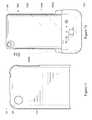
- FIG. 2shows the portable electronic device case, where the upper and lower case portions are assembled together.
- the portable electronic deviceis not shown in the case.
- FIG. 3shows a front view of the assembled case.
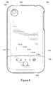
- FIG. 4shows a back view of the assembled case including a case button, indicator lights, a lens shield, and camera opening.
- FIG. 5shows a left side view of the assembled case.
- FIG. 6shows a right side view of the assembled case.
- FIG. 7shows a top side view of the upper case portion of the assembled case.
- FIG. 8shows a bottom side view of the lower case portion of the assembled case.
- FIG. 9shows a front view of the upper case portion.
- FIG. 10shows a front view of the lower case portion.
- FIG. 11shows a back view of the upper case portion
- FIG. 12shows a back view of the lower case portion.
- FIG. 13shows a left side view of the upper case portion.
- FIG. 14shows a left side view of the lower case portion.
- FIG. 15shows a right side view of the upper case portion.
- FIG. 16shows a right side view of the lower case portion.
- FIG. 17shows a top side view of the upper case portion only.
- FIG. 18shows a bottom side view of the upper case portion only.
- FIG. 19shows a top side view of the lower case portion only.
- FIG. 20shows a cross section of the case holding a phone when placed face down on a flat surface.
- FIG. 21shows a close-up top view of the built-in lens hood and the camera openings of the upper and lower case portions.
- FIG. 22shows a right side view of the assembled case including the camera opening.
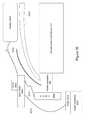
- FIG. 23shows a cross section of the lens hood between the camera openings of the upper and lower case portions.
- FIG. 24shows a diagram of the front of the assembled case with a portable electronic device in the case. There is a seam line where the upper and lower case portions meet.
- FIG. 25shows a back view of the assembled case where a region of the back surface is relatively flat.
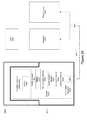
- FIG. 26shows a functional block diagram of the portable electronic device case with a battery that extends the battery life of the portable electronic device.
- FIGS. 27 and 28show tables listing operational modes of the portable electronic device case.
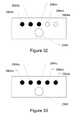
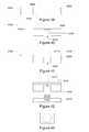
- FIG. 29shows an arrangement of indicator lights and a case button below the indicator lights.
- FIG. 30shows the rightmost indicator light turned on.
- FIG. 31shows the leftmost indicator light turned on.
- FIG. 32shows three indicator lights turned on.
- FIG. 33shows five indicator lights turned on.
- FIG. 34shows a circuit block diagram for electronic circuitry of the portable electronic device case.
- FIG. 35shows a layout view of the components for the lower case portion, as viewed from a back side of the lower case portion.
- FIG. 36shows a cross section of a portion of the lower case portion.
- FIG. 37shows a top view of a sound box portion of the case.
- FIG. 38shows a cross section of the sound box.
- FIGS. 39-42show steps in a process of making a flush indicator light covering for the case.
- FIG. 43shows a top view of the flush indicator light covering.
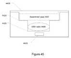
- FIG. 44shows a kit for a portable electronic case with a battery including a tray to hold the case and a cable.
- FIG. 45shows a cross section of an implementation of a tray for the kit. This tray has multilevel compartments.
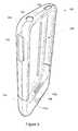
- FIGS. 1A-1Cshow a case that protects a portable electronic device 101 (e.g., smartphone, music player, or camera) from damage and also has a built-in battery to extend the battery life of the portable electronic device.
- FIG. 1Ashows an upper case portion 104 of the case
- FIG. 1Bshows a lower portion 108 of the case
- FIG. 1Cshows a representative portable electronic device 101 .
- This figuresshow the case and electronic device in a portrait mode orientation.
- the orientation of the casemay change (e.g., landscape mode orientation or upside-down orientation) or vary depending on the point of view or the orientation of the electronic device. So, the lower case portion may become the upper case portion, right-side case portion, or left-side case portion.
- the upper case portionmay become the lower case portion, right-side case portion, or left-side case portion. Regardless of the orientation, the case has two portions, where one case portion encloses a built-in battery.
- the lower case portionmay also be referred to as a first case portion and the upper case portion may be referred to as a second case portion.
- FIG. 2shows an assembled case 201 with upper and lower case portions joined together, but without the portable electronic device in the case.
- the caseprotects the portable electronic device and has openings which allow a user to access the features of the device. Further, the case includes a battery, enclosed within the lower case portion, to supplement the battery of the portable electronic device, thus increasing running time for the portable electronic device. Features and aspects of this case may be applied to cases for various portable electronic devices and device types.
- the portable electronic deviceis a smartphone.
- this patentdescribes the case as being for a smartphone.
- smartphonesinclude the Apple® iPhone, Blackberry® Storm, Blackberry® Pearl, Samsung® BlackJack, LG® Touch phones, and LG® Dare, and there are many others.
- the casecan be used with any type of battery-powered portable electronic device, where this device does not necessarily provide telephony functionality.
- the casemay be for a portable or handheld gaming device (e.g., Sony® PlayStation® Portable or PSP®, or Nintendo® DSTM), portable or palm-sized computer (e.g., OQO computer or Intel® AtomTM netbook), personal digital assistant (PDA), pager, audio player, video player, media player (Apple® Touch), cassette player, compact disc (CD) player, digital video disc (DVD) player, camera, video recorder, digital recorder, voice recorder, music recorder, digital audio recorder, or nonvolatile memory storage (e.g., Flash or phase-change memory).
- Appleis a trademark of Apple Computer Incorporated.
- Blackberryis a trademark of Research in Motion Limited.
- Samsungis a trademark of Samsung Electronics Company Limited.
- LGis a trademark of LG Electronics, Incorporated.
- Sonyis a trademark of Sony Corporation.
- PlayStation and PSPare trademarks of Sony Computer Entertainment Incorporated.
- Nintendois a trademark of Nintendo Company, Limited.
- Intel and Atomare trademarks of Intel Corporation.
- OQOis a trademark of OQO Incorporated.
- the smartphonehas a top side edge where there is a headset jack 112 and a sleep/wake button 116 .
- a headset jack 112On a left side edge, there is a ring/silent switch 120 and volume buttons 124 .
- a camera lens 128On a back of the device (not shown in FIG. 1C ), there is a camera lens 128 (indicated using broken lines).
- the phoneOn a bottom side edge of the device, there are speaker and microphone openings (not shown) and an electrical connector (not shown). Via the electrical connector, the phone can be charged or connected to another device, such as a computer or another smartphone, for synchronizing or transferring of files.
- another devicesuch as a computer or another smartphone
- a screen 132On a front of the device, there is a screen 132 , which may be a touch screen. Below the touch screen, there is a button 136 , and above the touch screen, a telephone receiver 140 (which a user can hold to an ear to hear a telephone conversation).
- upper case portion 104has on its top side (upper sidewall), a headset jack opening 144 and a button opening 148 , respectively.
- the upper case portionhas on its left side (left sidewall), a side opening 152 .
- lower case portion 108has a camera opening 156 and upper case portion 104 also has a corresponding camera opening (not shown in FIG. 1A ). The camera opening in the upper case portion lines up with the camera openings in the lower case portion.
- opening 204in the front, through which the user can view and access the touch screen, home button, and receiver.
- opening 204has a closed-polygon shape.
- the closed-polygon shapecan have any shape (e.g., square, trapezoid, pentagon, hexagon, octagon, star, circle, arch, or oval).
- the closed-polygon shapeis a rectangle with rounded corners.
- This closed-polygon shapeis formed by the merging of two open-polygon shapes.
- the upper case portionhas a first open-polygon front opening; this shape may generally be described as an upside down U.
- the lower case portionhas a second open-polygon front opening; this shape may generally be described as a U.
- To assemble the case togetherthe upper case portion is seated or fitted against the lower case portion. Then the upside-down U of the upper case portion joins with the U of the lower case portion to form the rectangular closed-polygon-shaped front opening shown in FIG. 2 .
- the lower case portionhas rubber strips 160 a and 160 b on a base front surface 164 .
- the stripsprotect and cushion the phone in the case.
- a back of the electronic deviceWhen placed in the case, a back of the electronic device will be placed against base front surface 164 .
- the base surfacehas a top edge 165 .
- an inside or inner connector 168On the lower sidewall is an inside or inner connector 168 , which is positioned and will connect to the electrical connector on the bottom side edge of the electronic device.
- To the left and right of the inner connectorare left speaker openings 172 a and right speaker openings 172 b .
- Each of the speaker openings 172 a and 172 bmay include one or more individual openings.
- a left speaker opening on the bottom side edge of the electronic devicewill be placed against left speaker openings 172 a .
- a right speaker opening on the bottom side edge of the electronic devicewill be placed against right speaker openings 172 b .
- the electronic device's microphone and speakerstransmit sound through these speaker (or audio) openings. More details on the speaker or audio openings are below.
- FIGS. 3-10show various other views of the case.
- FIG. 3shows a front view of the assembled case. Where upper 104 and lower 108 case portions meet, there is a seam line 304 . There are seam lines on either side (opposite sides) of front opening 204 .
- FIG. 4shows a back view of the assembled case.
- case button 408there are a case button 408 and indicator lights 412 a - e (e.g., light emitting diodes (LEDs) or other lighting sources).
- indicator lights 412 a - ee.g., light emitting diodes (LEDs) or other lighting sources.
- a synchronization (or sync) marking 416is around indicator light 412 e ; this marking is optional.
- the lower case portionincludes a lens shield or lens hood 420 (see also FIG. 12 ), which extends from camera opening 156 .
- Upper case portion 104also has a camera opening 424 for the camera lens; camera opening 424 is larger (i.e., larger diameter) than camera opening 156 . More details on the camera lens openings and lens shield are below.
- FIG. 5shows a left side view of the assembled case. Where the upper and lower case portions meet, there is a seam line that extends across the back and through the sides to the front.
- seam line 304is angled slightly with respect to a horizontal line.
- SM 1a distance is from the seam line to the bottom of the case.
- SM 2a distance is from the seam line to the bottom of the case. The angled seam line on the side is due to distance SM 2 being greater than distance SM 1 .
- FIG. 6shows a right side view of the assembled case.
- the seam lineis also angled in this side view.
- FIG. 7shows a top side view of the upper case portion of the assembled case.
- the speaker openings 172 a and 172 bare visible through the openings on the top side of the upper case portion. More details on camera opening 424 are below.
- FIG. 8shows a bottom side view of the lower case portion.
- the lower case portionhas an outside or outer connector 804 (e.g., a mini-B USB connector) and a grille or outside speaker opening 808 that are positioned on an outside bottom side.
- the outer connectorallows a user to connect the case and device via a cable (e.g., USB cable) to a power source or to synchronize with another electronic device.
- the outer connectoris positioned a bottom side edge of the lower case portion (or portion which encloses or conceals the battery).
- the outer connectormay be positions at other locations.
- the outer connectorcan be positioned on an outside right side edge of the lower case portion.
- the outer connectorcan be positioned on an outside left side edge of the lower case portion.
- the outer connectorcan be positioned on a back side (near or below the buttons and LEDs) of the lower case portion.
- the outer connectorcan be positioned on a front side (near or below the front screen opening) of the lower case portion.
- the outer connectormay be position on the case portion which does not have enclose the battery (e.g., upper case portion); then the connector is connected to the battery via wires or other electrical connectors.
- the outer connectorcan be positioned on an outside top or upper side edge of the upper case portion.
- the outer connectorcan be positioned on an outside right side edge of the upper case portion.
- the outer connectorcan be positioned on an outside left side edge of the upper case portion.
- the outer connectorcan be positioned on a back side of the upper case portion.
- the outer connectorcan be positioned on a front side (near or above the front screen opening) of the upper case portion.
- the outside speaker openingallows sound output (e.g., stereo sound output). Sound from the electronic device will travel through speaker openings 172 a and 172 b and output through openings 808 . Openings 172 a and 172 b are aligned with openings 808 , so a line passing through openings 172 a and 172 b will be parallel with lines passing through openings 808 . Note that openings 808 are made up of individual circular openings that are each smaller than the opening for outer connector 804 . In other implementations, however, there can be any number of openings, larger or smaller than the openings shown, and each opening may have a different shape. More details on the outer connector and outside speaker opening are below.
- FIG. 9shows a front view of the upper case portion.
- the upper case portionincludes a left sidewall 904 , a right sidewall 908 (opposite the left side wall), an upper sidewall 912 , and an upper interior surface 916 which connects to the left, right, and upper sidewalls.
- the upper interior surfaceis approximately perpendicular to the sidewalls.
- Sidewalls 904 , 908 , and 912generally form a three-sided rectangular frame with rounded corners (e.g., upside down U).
- the upper case portionalso has an open side end 919 (which would be the fourth side of the rectangular frame) that is opposite of upper sidewall 912 .
- FIG. 10shows a top view of the lower case portion.
- the lower case portionincludes front base surface 164 with strips 160 a and 160 b that run in a vertical direction (when viewing the case in a portrait orientation) on its surface.
- the electronic devicee.g., phone
- the electronic devicewill be placed on front base surface 164 and inserted (e.g., by sliding) into inner connector 168 , which holds the phone to the lower case portion.
- These insertsextend from a lower sidewall 1006 , which is generally shaped like a three-sided rectangular frame with rounded corners (e.g., U).
- a persontakes the upper case portion and slides it (through open side end 919 of the upper case portion) over the electronic device onto the lower case portion.
- the upper case portionslides onto the lower case portion through the open side end in a direction 1013 (i.e., vertical direction) along the base surface from the top edge to the lower sidewall.
- the material of the caseis a rigid hard plastic. Both upper and lower case portions are made of the same material.
- the upper case portionis formed of a shape to fit over the phone and lower case portions without need to stretch the upper case portion over the lower case portion.
- the case portions made of a relatively rigid materialcannot be stretched as much as, for example, gel, silicone, or rubber, without cracking or breaking. More details on the material of the case are below.
- the base front surfacegenerally has a contour that matches or conforms to the back of the phone or other device which will lie on the base front surface. For example, if the phone has a convex curved back, then the base front surface will have a concave curved surface.
- the base front surfacegives good support for the electronic device.
- a length of the base front surfaceis such that when an electronic device is placed on the base surface, the top edge base front surface is roughly aligned (e.g., same length, slightly longer, or slightly shorter) with a top side edge of the electronic device.
- Strips 160 a and 160 bextend in the vertical direction along base front surface 164 of the lower case portion.
- Strips 160 a and 160 bare typically a different material than the base front surface material and rise slightly above the base front surface.
- These stripscan be made of a material that has cushioning properties such as rubber, vinyl, polymer, plastic, foam (e.g., material with bubbles), or silicone. Depending on the material used, the strips may also be slightly tacky. These strips help cushion the electronic device and prevent it from becoming scratched or marred, especially when inserting the device into the lower case portion. The strips also help to gently grip the electronic device so that it does not inadvertently slide or become as easily dislodged from the lower case portion.
- the figuresshow a specific arrangement and number of strips, but in other implementations, there can be any number of strips in any arrangement. For example, there can be three, four, or more strips running in the lengthwise direction. Or the strips can run diagonally or horizontally on the base front surface. Further, in an implementation, the strips can be omitted entirely.
- the upper case portionslides over and onto the left and right inserts ( 1004 a and 1004 b ) of the lower case portion until being stopped by a raised lip 1008 of the lower case portion.
- This raised lipextends from the left insert along the back (see also FIG. 12 ) to the right insert of the lower case portion. Where the upper and lower case portions meet, the exterior surfaces become flush with each other.
- the upper case portionWhen the upper case portion is seated against the lower case portion, on a back side of the case, the upper case portion overlaps at least one portion of the lower case portion to hold the upper case to the lower case portion.
- the upper case portionoverlaps inserts 1004 a and 1004 b and a back base surface 1204 ( FIG. 12 ) of the lower case portion.
- the upper case portiongenerally holds onto the left and right inserts of the lower case portion through friction. Further, a distance from an outer surface of the left insert to an outer surface of the right insert can be typically slightly greater than an inner width of the upper case portion (i.e., into which the inserts will fit). This allows the upper case portion to hold onto the left and right inserts by compression.
- front opening 204which is generally a rectangular frame with rounded corners.
- the upper case portion's camera opening 424aligns with the lower case portion's camera openings 156 and 1208 .
- the camera lens of the phonewill have an unobstructed view through the camera openings of the lower and upper case portions.
- FIG. 11shows a back view of the upper case portion.
- There is an upper exterior surface 1104which is the opposite side of upper interior surface 916 .
- FIG. 12shows a back view of the lower case portion.
- Lens shield 420extends from camera opening 156 at base front surface 164 to opening 1208 at a base back surface 1204 .
- Camera opening 156is smaller (i.e., smaller diameter) than camera opening 1208 . Note that if the base surface is sufficiently shorter than the electronic device, camera opening 156 , lens shield 420 , and camera opening 1208 may be omitted or partially omitted from the lower case portion.
- the base back surfaceis a single piece (e.g., plastic) that has a base upper back surface 1209 and a base lower back surface 1212 .
- the base upper back surface and base lower back surfacecan be different sections of the base back surface.
- base upper back surface 1209 and base lower back surface 1212are individual pieces (e.g., two plastic pieces) that make up the base back surface (e.g., see FIG. 38 ).
- FIG. 13shows a left side view of the upper case portion.
- FIG. 14shows a left side view of the lower case portion.
- FIG. 15shows a right side view of the upper case portion.
- FIG. 16shows a right side view of the lower case portion.
- FIG. 17shows a top side view of the upper case portion (case not assembled), including headset jack opening 144 , button opening 148 , and camera opening 424 .
- FIG. 18shows a bottom side view of the upper case portion.
- FIG. 19shows a top side view of the lower case portion, showing inner connector 168 , left speaker opening 172 a , right speaker opening 172 b , and camera opening 1208 .
- the case shownhas specific openings sized, shaped, and positioned at particular locations. These openings are customized for smartphone 101 as described above and shown in FIG. 1C . It should be appreciated that there may be any number of openings in the upper and lower portions of the case to allow features of a portable electronic device to be accessible to a user.
- the openingsmay have any size, any shape, any combination of sizes, or any combination of shapes. There can be more, fewer, or different openings from those shown for the case in the figures.
- the openingscan be positioned at different locations than that shown.
- FIG. 20shows a cross section of a case with a phone, when placed face down on a table 2004 or other flat or relatively flat surface.
- the case with phonemay be placed on a countertop, vanity, hot tub edge, window sill, chair, sofa, or floor.
- the front of the casehas front opening 204 (see FIG. 2 ) and along a border of this opening are frame edges 2009 . These frame edges hold the phone in the case and also raise the phone slightly off the surface of the table.
- This featurehelps protect the front face of the phone from damage (e.g., scratching) since the front face does not touch the surface when in the face-down position.
- the usercan rub the face-down case and phone on the surface (as if sanding the surface using a sanding block), and the phone's front face and screen will not be damaged.
- the frame edges of the caseform a plane.
- This planeis generally, depending on a flatness of the table surface, approximately planar with a plane of the table surface.
- the frame edgesraise the phone's screen from about 0.25 millimeters to about 2.5 millimeters above the plane of the frame edges.
- a distance from the phone's screen to the table's surfacecan be 0.5, 0.8, 1, 1.2, or 1.5 millimeters.
- the phone's screenis coplanar to the table and a distance from the table to the screen is approximately 1 millimeter. This distance will vary depending on the flatness of the surfaces.
- front opening 204is smaller than the phone's front face.
- a length of the front openingis less than a length of the phone's front face.
- a width of the front openingis less than a width of the phone's front face.
- the front openingis generally rectangular and has a length of about 109.5 millimeters and a width of about 55 millimeters. The corners of the front opening can also be rounded (or square in other implementations).
- FIG. 21shows a close-up top view of built-in lens hood 420 and the camera openings of the upper and lower case portions.
- FIG. 22shows a side view of a camera opening 2230 for the assembled case.
- FIG. 23shows a cross section of the lens hood between the camera openings of the upper and lower case portions.
- the lower case portionwhich includes base front surface 164 and base back surface 1204 .
- Base front surface 164(see also FIG. 1 ) has camera opening 156 .
- Base back surface 1204has camera opening 1208 .
- the base front surface and base back surfaceform an enclosure 2309 between them, within which a battery 2317 for the case is housed. More details on the battery are below.
- Base back surface 1204has lens hood 420 which extends from camera opening 1208 toward base front surface 164 .
- Base front surface 164joins with base back surface 1204 , and camera opening 156 aligns with lens hood 420 .
- camera opening 424 of upper case portion 104aligns with the camera openings in the lower case portion.
- the lens hoodhas about a 31 degree field of view. In other implementations, however, the field of view can be any desired number of degrees, less than or greater than 31 degrees.
- the angle of view provided by the casewill depend on the field of view of the camera of the phone and will generally be at least as wide as the camera's field of view, so that the lens hood will not appear in the photos taken by the camera.
- the camerahas a field of view of about 30-32 degrees, and the corresponding camera opening in the case is at least about 30-32 degrees or wider.
- the angle of view of the camera openingcan range from about 25-60 degrees.
- the lens hood for the lower case portionhas a length of about 3.7 millimeters from opening 156 to opening 1208 .
- the length of the lens hoodcan be any desired length and vary on a number of factors such as a thickness of the battery.
- the hood lengthcan vary from about 2.8 millimeters to about 5 millimeters. The length can be less than 2.8 millimeters (e.g., for a thin battery) or greater than 4.5 millimeters (e.g., for a jumbo battery).
- the thicker battery 2317is, the longer the lens hood.
- a thicker battery(for the same two-dimensional area) also usually means greater battery capacity.
- the casehas the camera openings to allow a user to take pictures with the phone's camera without removing the phone from the case.
- the phone's camera lensaligns behind the lower case portion's camera openings 156 and 1208 , and the upper case portion's camera opening 424 so that the camera lens' view is unobstructed. A picture taken with the phone in the case will not capture the sides or edges of the camera openings.
- the built-in lens hood of the caseis a feature that improves the picture taking of the camera. Without a lens hood, sun or other light can more easily strike the camera lens and cause unwanted flaring, glare, uneven lighting, and shadows in the photos.
- the lens hood of this casehelps prevent such undesired effects.
- the lens hoodalso protects the lens of the camera.
- the lens hoodprotrudes from the camera lens a certain distance, preventing inadvertent touches and scratches to the lens. Without a lens hood, the camera lens is more vulnerable to accidental contact (e.g., bumping against a surface), potentially resulting in damage to the camera lens.
- the lens hoodalso helps to shelter the camera lens from dust, rain, and other elements. Without a lens hood, for example, rain drops can more easily hit the camera lens. The lens hood of this case helps prevent such damage.
- the area of camera opening 1208is greater than the area of camera opening 156 .
- a lens hood surface between the two camera openingsis conical or frustoconical.
- the greater the size of camera opening 1208 is as compared to camera opening 156helps to increase the peripheral field that can be captured by the camera and helps to ensure that the camera does not capture the sides or edges of camera opening 1208 when taking pictures.
- the area of camera opening 424is greater than the area of camera opening 1208 .
- camera openings 156 , 424 , and 1208are circular.
- the camera openingscan be any shape or closed polygon (e.g., not a semicircle or arc), such as a triangle, square, rectangle, trapezoid, or other.
- openings 156 , 424 , and 1208will have a similar shape and openings closer to the camera lens will be smaller than those further away.
- a cross-sectional area of a closed-polygon opening 156will be less than a cross-sectional area of a closed-polygon opening 1208 , which will be less than a cross-sectional area of a closed-polygon opening 424 .
- the inside diameter of camera opening 156is approximately 6 millimeters
- the diameter of camera opening 1208is approximately 11-12 millimeters
- the diameter of camera opening 424is approximately 12.2 millimeters.
- the diameters of the openingscan have any desired size or shape.
- opening 156can range from about 2 millimeters to about 12 millimeters.
- Opening 1208can range from about 4 millimeters to about 24 millimeters.
- Opening 424can range from about 5 millimeters to about 25 millimeters.
- a ratio of opening 1208 to opening 156is from about 1.7:1 to about 2.25:1. Generally, the openings are larger than the camera lens and sufficiently large so that the case does not appear in photographs.
- FIG. 24shows the front of a case with an electronic device in the case.
- the upper case portionslides over the lower case portion.
- the seam line(from 2404 a to 2404 b ) runs around the entire case (e.g., across the back of the case).
- FIG. 4shows the seam line for the back
- FIGS. 5 and 6show the seam lines for the sides.
- the surfaces of the lower and upper case portionsare relatively flush with each other. The seam line remains visible and can be felt tactilely.
- seam line for the caseis positioned to ensure the upper and lower case portions are securely attached to each other.
- seam lines 2404 a and 2404 bare positioned so that they align with a bottom edge of screen 132 of the phone. As shown in FIG. 24 , with the phone in the case, the bottom edge of touch screen 132 is in-line with lines 2404 a and 2404 b .
- the seam linescan be at other positions. For example, the seam line can be aligned with an upper edge of screen 132 , or anywhere between the upper and lower edges of the screen.
- the upper case portionsecurely engages (e.g., by overlapping) to the phone and lower case portion, so the upper case portion will not inadvertently slide off or otherwise detach. Also, in an implementation, when the user grips the phone in a portrait orientation, part of the hand (e.g., thumb and forefinger) is holding onto the upper case portion, while the palm of the hand is pushing against the lower case portion (urging the lower case portion toward the upper case portion).
- part of the hande.g., thumb and forefinger
- aligning seam lines 2404 a and 2404 b with the bottom edge of the touch screenprovides for a symmetrical arrangement and appearance of the visual elements of the phone and case. This enhances the smartphone experience for the user, allowing the user to easily locate the display both visually and tactilely (because the user can feel for the seam).
- the seam lineis at about 30 millimeters from a bottom edge of the case.
- a case lengthis about 130 millimeters.
- This seam linedivides the case at about 0.23 of the whole.
- the seam linecan be at other positions (e.g., ranging from about 15 millimeters to about 50 millimeters) and have other ratios (e.g., ranging from 0.10 to 0.50 of the whole).
- the seam lineis at about 35 millimeters from a bottom edge of the case.
- a case lengthis about 130 millimeters.
- This seam linedivides the case at about 0.27 of the whole.
- the seam linecan be at other positions (e.g., ranging from about 15 millimeters to about 50 millimeters) and have other ratios (e.g., ranging from 0.10 to 0.50 of the whole).
- seam lines 2404 a and 2404 b in the front of the caseare about X of a length of the joined case, and a seam line for the back of the case is about Y of a length of the joined case.
- X and Yare numbers and Y is greater than X.
- the seam line for the front and backdiffer because the seam line is angled on the sides of the case (see FIGS. 5 and 6 ). In other implementations, the seam line can be angled even more on the sides so that a difference between the ratios in the front and back is greater. The seam line can be angled less on the sides so that a difference between the ratios in the front and back is less or 0, or the ratio is larger in front and less in back.
- a distance 2416 between a bottom edge of front opening 204 and the seam lineis about 16 millimeters.
- a length of front opening 204is about 109.5 millimeters. Therefore, the seam line divides the front opening at about 0.146 of the whole.
- distance 2416can vary, depending on for example the screen size, in a range from about 8 millimeters to about 32 millimeters. The seam line will divide the opening in a range, for example, from about 0.10 to about 0.50 of the whole.
- FIG. 25shows a back view of the assembled case where a region of the back surface, indicated by box 2504 , is relatively flat.
- the flat portion of the back surfaceensures the electronic device and case will be stable (e.g., not rock back and forth) when the case is placed on its back on a table. See also FIGS. 5-8 which show various views of the case's flat back surface. Even if the electronic device does not have a flat back, the flat portion of the case ensures the electronic device will be stable when placed on a table.
- both the upper and lower case portionshave sections which are flat. Where the upper and lower case portions meet, a seam line 2508 divides the upper and lower case portions. As shown, the flat case section of the lower case portion is smaller in terms of area than the flat section of the upper case portion. The seam where the upper and lower case portions meet is flush, so the seam does not cause the case to be unstable.
- the flat back surfaceensures stability when the case is placed on its back, regardless of how the back of the phone is shaped.
- This featurecreates a steady and stable surface and ensures that the electronic device will not slide or wobble as a result of being placed, for instance, on a table.
- an electronic devicemay be curved in all directions (e.g., no flat surfaces at all) or have a design where the back will not be stable when placed on a table.
- the designmay have notches, indentations, or other structures (possibly ornamental) that cause the phone to not lie stably on its back. Despite this, when the phone is in the case, because of the flat back, the case will rest securely on its back.
- rectangular flat surface 2504is centered in back of the assembled case. That is, the distance surrounding the flat back surface is equal at opposite sides. In other implementations, however, the flat back surface may be located anywhere on the back of the case portions. Further, the flat back surface may be of any size, any shape, any combination of sizes, or any combination of shapes. For example, the flat back surface may have a circular or oval shape. The flat region may be rectangular with rounded corners.
- the flat back surfaceis typically sufficiently sized to make the case stable when placed on its back.
- the size of the flat back surfacecan vary and the proportion of the area ( 2504 ) that is flat to the area that is not flat (case back outside box 2504 ) can vary.
- the flat back surface areais larger than the electronic device the case is holding.
- the flat back surface areacan be larger than a flat back surface area provided by the electronic device itself.
- dimensions for flat surface section 2504are about 100 millimeters by about 40 millimeters. Dimensions for the case are about 130 millimeters by about 66.2 millimeters.
- the area ratio between the flat surface section 2504 and the total case dimensionsis about 0.465 (i.e., 4000 square millimeters/8606 square millimeters). However, in other implementations, the ratio can be in the range from about 0.333 to about 0.6.
- a distance between a bottom edge of the lower case portion and a bottom edge of the flat back surfaceis about 13 millimeters.
- a distance between a top edge of the upper case portion and a top edge of the flat back surfaceis about 13 millimeters.
- a distance between a left edge of the assembled case and a left edge of the flat back surfaceis about 15 millimeters.
- a distance between a right edge of the assembled case and a right edge of the flat back surfaceis about 15 millimeters.
- FIG. 26shows a functional block diagram of a case for holding a portable electronic device 2601 having a battery 2604 .
- the casehas an upper case portion 2608 and a lower case portion 2612 .
- the electronic deviceis inserted into the lower case portion and is connected to inner connector 168 , and the upper case portion slides over the electronic device and a portion of the lower case portion.
- the lower case portionincludes a circuitry 2616 which is connected to inner connector 168 , a case battery 2317 , a battery status indicator 2620 , a synchronization indicator 2624 , a user input element 2628 , an outer connector 2632 , and audio-video (AV) openings 2636 .
- a cable 2640 having connectors 2644 and 2648may be used to connect the case to a computer 2652 , a power source 2656 , or both.
- this applicationdiscusses the portable electronic device as being a smartphone.
- the portable electronic devicecan be any device type and may be a device other than a telephony device.
- smartphones and other portable electronic devicesinclude a multitude of other features. These features include data storage, music playing, picture taking, video recording, and games. Further, these devices include vivid color displays, cameras, speakers, speakerphone, nonvolatile storage, touchscreens, and others. Such features use power. And the more such features are used, the shorter the battery life.
- the casewith its built-in battery (i.e., battery 2317 ), alleviates this problem by providing additional power to the phone.
- Various implementations of the casedouble, triple, or quadruple the battery life of the phone or the amount of time that the user can use the phone.
- FIGS. 27 and 28show tables listing the various modes.
- the usercharges the case battery. To do so, the user connects a power source via a cable (e.g., USB cable) to the case's outer connector (e.g., mini-B USB connector).
- a cablee.g., USB cable
- the case's outer connectore.g., mini-B USB connector
- the casewill be in a power-up mode (described in FIG. 27 ) during which at least one of the indicator lights (e.g., LEDs) of the case lights momentarily.
- the phonedoes not need to be in the case; but if the phone is in the case, the user will be able to use the phone normally. This may be referred to as a normal operating mode for the phone.
- the indicator lightsWhen entering the power-up mode, the indicator lights turn on in order to indicate to the user that the case has been powered up. Power-up may be indicated to the user using any visual (or audible) indication. In a specific implementation, for example, one of the LEDs turns on for a short time and then turns off. In another implementation, each of the LEDs may turn on and off in sequence. In another implementation, at least one LED turns on and stays on while the case is connected to a charging source. In this implementation, the number of lights turned on is proportional to the battery life and the number of lights increases as the battery life increases.
- FIG. 29shows a specific arrangement of indicator lights 2904 a - e (e.g., LEDs, laser diodes, light bulbs, neon bulbs, or other lighting) for the case, where a case button 2908 is centered below the indicator lights.
- a line extending between indicator light 2904 a and 2904 bdoes not pass through case button 2908 .
- the indicator lightsare positioned horizontally on the back of the lower case portion and a line segment extends from indicator lights 2904 a - e .
- the case buttonis positioned transverse to the line segment and equidistance to ends of the line segment.
- the indicator lights and case buttonhave a circular shape.
- the indicator light cover and case buttonare flush with the case surface.
- the case buttonis located near the indictor lights.
- the case buttoncan have any shape (e.g., square, rectangle, triangle, and oval) and may be located anywhere on the case.
- the indicator lightsare positioned horizontally on the back of the lower case portion (see FIGS. 4 and 12 ), in other implementations the indicator lights can be in a different location or be arranged differently (e.g., off-center or vertically arranged). Also, there may be any number of lights (e.g., 0, 1, 2, 3, 4, 5, 6, 7, or more than 8) and the openings for the indicator lights may have any shape (e.g., circle, square, rectangle, or triangle).
- the right-most indicator light ( 2904 e )turns on momentarily and then turns off (e.g., flashes or blinks) to indicate that the case is connected to a power source.
- the power sourcemay be a power socket, power receptacle, or power outlet in the user's home or office.
- the cablemay be connected to a cigarette lighter socket in the user's car or boat. This allows, for example, the user to charge the case battery while driving.
- the cablecan be connected to a computer's USB port or any other power source.
- FIG. 27describes the charge case battery mode. Power from the cable connected to the case outer connector will charge the case battery. Circuitry (described below) in the case will control charging of the battery until it is fully charged.
- the usercan press the case button and determine the battery life remaining in the case battery by reading the fuel gauge.
- the case buttonUpon pressing the case button, the case will be in a fuel gauge mode as described in FIG. 27 . If the case battery is charged, an appropriate number of indicator lights will light to indicate a charge level of the case battery. To enter this mode, the phone does not need to be in the case; but if the phone is in the case, the phone will be in normal operating mode.
- the case battery lifemay be indicated to the user using any visual (or audible) indication.
- the indicator lightsturn on from left to right and each indicator light that turns on indicates an additional level of charge for the case battery.
- the number of LEDs lighting upis proportional to the case battery life.
- the indicator lightsturn on from right to left and each indicator light that turns on indicates an additional level of charge for the case battery.
- the lighting indicatorsemit a blue or bluish light (e.g., blue LED).
- the lighting indicatorscan emit any color or wavelength of light as desired.
- the colorcan be red, green, yellow, white, or purple, or any combination of these.
- two different indicator lights of the same casecan emit two different colors.
- the color of the lightmay be a result of the LED color itself or a cover over the LED light (e.g., white LED light is covered by a bluish lighting cover).
- FIG. 29shows a specific implementation where no indicator lights turn on, indicating the case battery is discharged or has a very low level of charge.
- FIG. 31shows the leftmost indicator light ( 2904 a ) turning on, indicating that the case has a minimal charge. More indicator lights turn on in FIG. 31 than in FIG. 29 , indicating that the case battery in FIG. 31 has a higher level of charge than the case battery in FIG. 29 .
- FIG. 32shows three indicator lights ( 2904 a - c ) turning on to indicate an approximately half-charged battery. A greater number of lights turn on in FIG. 32 than in FIGS. 29 and 31 , indicating that the case battery in FIG. 32 has a higher level of charge than the case battery in FIGS. 29 and 31 .
- FIG. 33shows a specific implementation of five indicator lights ( 2904 a - e ) turning on to indicate a fully charged battery. A greater number of indicator lights turn on in FIG. 33 than in FIG. 32 , indicating that the case battery in FIG. 33 has a higher level of charge (e.g., more juice) than the case battery in FIG. 32 .
- the phoneWhile charging the case battery in the charge case battery mode, the phone does not need to be in the case. If the phone is in the case, the case will also be in the charge phone battery mode listed in FIG. 27 . When the phone battery becomes discharged, the case battery will, via inner connector 168 , charge and top off the phone's battery as needed. The case will continue to charge the phone battery as needed until the case battery becomes completely discharged.
- the casecan be in the charge phone battery mode as long as there is charge in the case battery, but the case will no longer be in the charge case battery mode.
- the caseWhen the user connects a power source via a cable (e.g., USB cable) to the case's outer connector, the case will be placed in charge phone battery mode. The case will continue to charge and top off the phone battery as needed. Also see discussion regarding sleep mode below.
- a cablee.g., USB cable
- the phonemay indicate to the user that the phone is charging.
- the phone's screendisplays an icon (e.g., lightning bolt) to indicate that the phone is charging.
- the phone's screeninforms the user (e.g., icon changes from a lightning bolt to a plug symbol).
- the casealso has a battery gauge such as shown in FIG. 29 . While in the charge phone battery mode, the user can press the case button and determine the case battery life remaining by reading the fuel gauge. Upon pressing the case button, the case will simultaneously be in the fuel gauge mode.
- the fuel gauge modeis described in FIG. 27 and above.
- the caseIf the case is not connected to a power source and the case battery is at a charge level below a certain threshold (i.e., a sleep mode level of charge), the case will enter a sleep mode. For example, when the case battery is completely discharged, the case will be in sleep mode.
- a sleep mode level of chargei.e., a certain threshold
- the sleep modeis described in FIG. 27 . While in the sleep mode, the case becomes inactive (e.g., the case button and case indicator lights are not functional) and the user will be unable to get a battery reading. The sleep mode will not affect the phone. The phone will be in normal operating mode as long as the phone has sufficient charge. The case will not draw any power from the phone.
- the userconnects power to the outer connector of the case in order to charge the case battery.
- the case batterywill be charged for some amount of time before charging of the phone battery begins. For example, this amount of time may be about five minutes, but the exact amount of time (e.g., two, three, six, or more minutes) will depend on a number of factors including the charging current and the level of charge remaining in the battery. The amount of time will vary depending on how long it will take for the case battery to be charged to a level above the sleep mode level of charge.
- the case batteryWhen the case battery has been charged above the sleep mode level of charge, the case exits sleep mode and enters power-up mode.
- the case batterywill be used to charge the phone battery, as needed.
- the case button and case indicator lightswill work. When the user presses the case button, the user will get a battery reading from the fuel gauge.
- the phone batterymay need to be charged to some level before becoming active and operate normally. For example, this amount of time may be about five minutes, but will vary depending on the charging current and level of charge of the phone battery.
- the sleep modewhen the user connects a power source via a cable (e.g., USB cable) to the case's outer connector, the case will immediately charge the phone battery and the case battery. Both the phone and case batteries will be charged in parallel. The power from the USB cable is used to charge the phone battery even if the case battery does not have a minimum level of charge.
- a cablee.g., USB cable
- the casehas an extended sleep mode, which is not the same as the sleep mode described above.
- the extended sleep modeis described in FIG. 28 .
- the caseenters the extended sleep mode when no phone is connected to the case and power is not connected to the outside connector of the case.
- circuitry of the caseWhen in the extended sleep mode, circuitry of the case will use less power so the case will retain its battery power for relatively longer periods of time. For example, for the extended sleep mode, some inactive circuits or portions of the circuit will be turned off so they do not draw power.
- the extended sleep modeextends the case battery life.
- the casewill retain charge seven weeks or more (when starting with a fully charged case battery).
- the battery life during extended sleep modecan vary and may be one week, ten days, two weeks, three weeks, six weeks, less than one week, or more than seven weeks.
- the usercan exit the extended sleep mode by any one of three ways.
- An implementation of a case of the inventioncan have any one of or a combination of the following three ways to exit the extended sleep mode.
- the userwill insert the phone into the case.
- the caseenters initial phone connect mode (described in FIG. 28 ) during which the circuitry in the case authenticates with the phone.
- the case circuitryincludes an authentication chip which allows the case to communicate with the phone. If the case does not have this authentication chip, the case is not authenticated.
- the case circuitryimplements a handshaking protocol by sending a self-identification signal to the phone. If the phone recognizes the signal, the phone can accept the signal and authenticate the case. If the phone does not recognize the signal, the case is not authenticated.
- the authentication processuses certificates, which get exchanged with the electronic device and opens up communication channels once these certificates have been exchanged and authenticated.
- the phoneUpon putting the phone in the case, if the case authenticates with the phone, the phone will display its normal screen and no warning messages regarding the case will appear on the phone screen.
- the phone screendisplays a warning message.
- This warning messagemay be referred to as a “nag message,” informing the user that the case is not a valid accessory or has not been approved by the manufacturer of the phone.
- the warning messageis “This accessory is not designed for this phone. This accessory might cause interference, do you wish to enable airplane mode?” and will appear on the phone's screen.
- the phonewill enter a normal operating mode and the user can continue using the phone normally.
- the case batterywill provide extended battery life for the phone.
- the usercan synchronize the phone with a second electronic device. To do so, the user pushes and holds the case button for about three seconds. The case will enter a synchronization or sync mode described in FIG. 28 .
- the period of time for which the user holds the case button for to enter the sync modecan be set to any value, such as in a range from two to fifteen seconds; the longer the time period, the less likely the user can accidentally enter the sync mode.
- the second electronic deviceis a computer. While in the sync mode, the case is ready for the phone to synchronize with the computer. If the case is connected to a computer via the cable (e.g., USB cable), the user can synchronize data between the phone and the computer, send data from the phone to the computer, send data from the computer to the phone, or any combination of these. Synchronization includes synchronizing calendar information, contact information (e.g., names, addresses, phone numbers), music files, video files, and e-mail between the phone and the computer.
- the cablee.g., USB cable
- the phoneWhile the case is in the sync mode, the phone is also in a sync mode when the phone is ready to transfer or receive data from the computer.
- the usercan determine the status of the phone by looking at its screen.
- the phone's screenmay display a sync status symbol or a not charging symbol, or both.
- the second electronic devicemay be an electronic device (e.g., mobile phone, PDA, smartphone, pager, audio player, media player, portable media player, game console, server), software (e.g., iTunes or Windows Media Player), or a service (e.g., iTunes Store, Urge, or Rhapsody).
- an electronic devicee.g., mobile phone, PDA, smartphone, pager, audio player, media player, portable media player, game console, server
- softwaree.g., iTunes or Windows Media Player
- a servicee.g., iTunes Store, Urge, or Rhapsody
- the casedoes not need to be connected to a computer to enter the sync mode. If the user connects the case via the cable to a computer within about 30 seconds, then the user will be able to synchronize the phone with the computer. If the user does not connect the cable to a computer within 30 seconds, however, the case will automatically exit the sync mode (e.g., returning to the charge phone battery mode).
- An automatic time out of 30 seconds for the synchronization modeis provided as an example, and the time out value can vary from about 3 seconds to about 3 minutes. For example, the time out value can be 15, 40, 50, 60, 180, or 360 seconds.
- the caseupon entering the sync mode, the case exits other modes. For example, if the case is in the charge case battery mode, the case will exit this mode upon entering the sync mode and the case battery will stop charging. Similarly, if the case is in the charge phone battery mode, the case will exit this mode upon entering the sync mode and the case will stop charging the phone battery.
- the sync modemay be indicated to the user using any visual (or audible) indication.
- a synchronization indicatorindicates to the user that the phone is ready to be synchronized with the computer.
- the synchronization indicatormay also indicate when the phone is not ready to be synchronized, whether or not the synchronization is complete, whether or not there was an error in synchronization, and so forth.
- Synchronizationcan be indicated via the indicator lights. For example, a lighting of an LED will indicate to the user that the case is in the sync mode. In a specific embodiment, for example, one of the LEDs blinks continuously. In other embodiments, a different number of LEDs blink continuously or a number of LEDs blink twice and turn off. In a specific embodiment of the sync mode, as shown in FIG. 30 , LED 2904 e will blink continuously to indicate to the user that the phone is ready to synchronize with another device.
- the casemay be unable to enter the sync mode under certain circumstances. For example, when the case is in the sleep mode, the case button and indicator lights do not work. The phone cannot synchronize with another electronic device because the case requires a minimal amount of power for its electronic board to support the synching mechanism. So, if the user pushes and holds the case button for three seconds, this will have no effect on the case and the case will not enter the sync mode.
- the usercan exit the sync mode (described in FIG. 28 ) by any one of three ways.
- An implementation of a case of the inventioncan have any one of or a combination of the following three ways to exit the sync mode.
- the usercan only exit the sync mode using the first two options and not the third option. So, once the case is in the sync mode, the user cannot exit the sync mode by pressing the case button. This prevents the user from inadvertently exiting the sync mode by intentionally or unintentionally pressing the case button.
- the indicator lightsWhen the case exits the sync mode, the indicator lights will turn off (or turn on) to indicate that the case is no longer in the sync mode. For example, when indicator light 2904 e blinks continuously to indicate the sync mode, this indicator light turns off to indicate the case is no longer in the sync mode.
- the phoneWhen the case exits the sync mode, the phone will also exit the sync mode and no longer transfer data to and from the computer. Upon exiting the sync mode, the phone will enter the normal operating mode and the user can use the phone normally (e.g., make a phone call to Stephan Schiffer, send a text message to Beyonce, play a Nena song, play computer baseball with Tim Lincecum, or call Jenny at 867-5309).
- the phonewill enter the normal operating mode and the user can use the phone normally (e.g., make a phone call to Stephan Schiffer, send a text message to Beyonce, play a Nena song, play computer baseball with Tim Lincecum, or call Jenny at 867-5309).
- the case batteryis typically a rechargeable type.
- the case batteryis a rechargeable lithium-ion polymer battery. This battery can be charged, used, and recharged many times (e.g., about 500 times).
- Other rechargeable battery typesmay be used.
- some other rechargeable type batteriesinclude nickel cadmium (NiCd), nickel metal hydride (NiMH), lithium ion, lithium polymer, lead acid, and other rechargeable battery chemistries.
- the case batteryis integrated with the case and the battery is not replaceable by the user.
- One benefit of this designis that it allows for a smaller and more compact case as compared to a case with a replaceable battery because there is no additional interface (e.g., battery cover) that interferes with the profile of the case.
- the batteryis replaceable by the user.
- the batterymay be a rechargeable type such that after the battery has been drained and recharged after a threshold number of cycles, the battery is replaceable by the user.
- the batterymay be a disposable battery (e.g., N, AA, AAA, or C cell battery) such that after the battery is drained, the user removes the drained battery from the case, and installs a new battery.
- the user input elementallows a user to communicate with the case.
- the user input elementis a button that the user can push. Pushing the button displays the battery status indicator, the synchronization indicator, or both.
- at least one LEDfunctions as a battery status indicator and as a synchronization indicator.
- pushing the button for a first threshold time periodlights a first LED in a first mode. In the first mode, the LED is solid and indicates a battery status.
- Pushing the button for a second threshold time periode.g., 2, 3, 4, 5, 6, 7, or 8 seconds
- the LEDis blinking and indicates a synchronization status.
- the modes associated with a patternmay vary. For example, to indicate a battery status, an LED may blink twice or all the LEDs may flash one after the other from left to right. Also, a blinking LED in a first pattern may indicate that the phone is ready to be synchronized. A blinking LED in a second pattern, different from the first pattern, may indicate that synchronization is complete.
- the blinksmay be in any pattern. Some examples of patterns include a long blink, followed by a short blink; two long blinks followed by three short blinks; one short blink, followed by two long blinks. In a specific implementation, all the LEDs blink twice to indicate there is a problem with recharging the battery.
- the user input elementsmay not necessarily be a button.
- the user input elementmay be a microphone to accept a voice command from the user.
- the user input elementmay be a touch screen or a sliding switch that the user slides back and forth.
- the audio-video (A/V) openingsinclude one or more holes or openings in the lower case portion, the upper case portion, or both. These openings direct audio information, video information, or both from the phone to the user. These openings also allow the phone to receive audio information, video information, or both.
- the cablemay, be any type of cable having any number of wires that can electronically connect the case to the computer or power source.
- the cableis a USB cable (e.g., USB 2.0 cable) where connector 2644 is a USB mini-A plug (or male connector) and connector 2648 is a USB type-B plug (or male connector).
- USB 2.0 cablee.g., USB 2.0 cable
- connector 2644is a USB mini-A plug (or male connector)
- connector 2648is a USB type-B plug (or male connector).
- the cableallows battery 2317 , battery 2604 , or both to be charged by the computer, power source, or both.
- the cablealso allows the portable electronic device and the computer (or other device) to be synchronized.
- connector 2648is plugged into an automotive cigarette lighter plug (e.g., 12 volt automotive lighter plug, 6 volt automotive lighter plug), a type A flat blade electrical plug, or a type B flat blade with round grounding pin plug.
- automotive cigarette lighter pluge.g., 12 volt automotive lighter plug, 6 volt automotive lighter plug
- type A flat blade electrical pluge.g., 12 volt automotive lighter plug, 6 volt automotive lighter plug
- type B flat blade with round grounding pin pluge.g., 6 volt automotive lighter plug
- different parts of the worlduse different types of electrical plugs.
- a type C plugis common in Europe.
- the U.S. Department of Commerce, International Trade Administration publication Electric Current Abroad, 1998 edition, reprinted 2002which is incorporated by reference, describes different types of electrical plugs used in different parts of the world, which are suitable for use as connector 2648 of the present invention.
- the length of the cableranges from about 0.3 meters to about 5 meters.
- the cablemay also be less than 0.3 meters or more than 4.9 meters.
- the variations in cable lengthreflect the many different preferences that users may have. For example, some users may desire a longer cable so that they can place the case further away from the second electronic device. Other users may desire a shorter cable to lessen the likelihood that the cable will become tangled.
- the outer connectorincludes wireless capabilities.
- the outer connectormay be a wireless transceiver, a wireless receiver, or a wireless transmitter. This allows the case and computer or power source to communicate wirelessly.
- Such wireless communicationmay be accomplished using any wireless technology (e.g., infrared, Wi-Fi, Bluetooth, radio frequency, microwave, 802.11, 802.11a, 802.11b, 802.11g, 802.11-2007, and 802.11n, or wireless USB).
- wireless featuresmay also allow batteries 2317 , 2604 , or both to be wirelessly charged (e.g., resonance charging).
- FIG. 34shows a circuit block diagram for the case. This diagram shows more details of circuitry 2616 and components of lower case portion 2612 . The circuit blocks in this figure implement the functionality and modes of the case described above.
- the casehas a connector 3404 for connecting to a portable electronic device 3408 which the case is designed for.
- the portable electronic deviceis a smartphone having a 30-pin connector.
- the casehas a corresponding 30-pin inner connector that fits into the phone's connector.
- the caseincludes a male inner connector that fits into the phone's female connector.
- the case's inner connectorcan have any number or combination of pins and shapes in order to interface with the portable electronic device that the case is designed for.
- the case circuitryinterfaces with the phone, such as for charging the phone's battery and synchronizing.
- power from a lithium battery 3412is passed through a DC-to-DC converter block 3416 and connector 3404 to the phone.
- input-output (I/O) via a mini-USB connector 3420is passed through wires 3424 (i.e., differential D+ and D ⁇ signals) through USB resistors 3428 , converter 3416 , connector 3404 to the phone.
- USB mini-Be.g., USB mini-B
- other connectorsmay be used such as USB type A, type B, mini-A, micro-AB, or micro-B.
- other types of connectorssuch as FireWire (i.e., an IEEE 1394 interface, i.LINK, or Lynx), eSATA, or a proprietary connector may be used instead or in addition.
- analog datacan be converted to digital data for the phone.
- Digital data from the phonecan be converted into analog form for further processing, or vice versa.
- A/D converter circuit 3432is connected to battery 3412 and is used to collect analog measurement information (e.g., voltage level) about the battery. This information is converted to digital form by the A/D converter and used in the fuel gauge algorithms (see discussion on fuel gauge mode above) to determine and indicate the charge level of the battery.
- the electronic devicelooks for an authentication or handshaking signal (e.g., sending of an authentication code). If the device does not receive the proper authentication, the device may display a message (e.g., nag message) that the case is not an authorized peripheral for the device or the device can simply not allow the case circuitry to interface with the phone (e.g., not allow charging or synchronization).
- an authentication or handshaking signale.g., sending of an authentication code
- An authentication circuit 3440can be included in the circuitry to provide proper authentication to the electronic device.
- This authentication circuitcan connect to the other circuitry of the case through a microcontroller (uC) 3444 interface.
- microcontroller 3444is the ATMega32 from Atmel.
- the userWhen the authentication circuit is present, the user, for example, will not see a nag message on the phone. In an implementation, when the authentication circuit is not present, the user will see a nag message, but afterwards, the case will still function (e.g., provide the functionality described in the tables in FIGS. 27 and 28 ) with the device.
- case battery 3412has lithium-ion polymer battery 3412 to provide extra charge and capacity for the phone. See above discussion for more detail on the functionality.
- case battery 3412has a nominal capacity of 1390 milliamp-hours. The capacity can range from about 1330 milliamp-hours to about 1490 milliamp-hours. In comparison, the electronic device's battery capacity is approximately 1150 milliamp-hours. So, with the addition of case battery 3412 , the device's battery life will approximately double.
- the case batteryhas a length of about 74 millimeters, a width of about 41 millimeters, and a thickness of about 4.2 millimeters (after swelling).
- a weight of the batteryis about 28 grams.
- a discharging operating temperature for the batteryis about ⁇ 20 degrees Celsius to about 60 degrees Celsius.
- the batterycan be recharged using a standard charging current (665 milliamps at 4.2 volts) in about 2.5 hours or a rapid charging current (1330 milliamps at 4.2 volts) in about 1.5 hours.
- the batteryprovides an output voltage of about 3.7 volts.
- the caseincludes circuitry for charging case battery 3412 .
- Poweris supplied through USB connector 3420 to a battery charging circuit 3448 , which is connected to the battery.
- the battery charging circuitsupplies the voltages and currents to the battery for charging, and can detect when the battery is fully charged (at which point circuit 3448 stops charging the battery).
- the charging circuitcan also include a DC-to-DC converter to convert the voltage received at the USB connector (e.g., 5 volts) to the voltage used to charge the battery (e.g., 4.2 volts).
- Battery charging circuit 3448may be implemented using an integrated circuit manufactured, for example, by Linear Technology Corporation, Maxim Integrated Products, Incorporated, or National Semiconductor Corporation.
- a battery control circuit 3452is connected to battery charging circuit 3448 to control its operation.
- the battery control circuitcan direct the charging circuit to charge the battery or stop charging the battery, such as when the user wants to enter the synchronization mode.
- case battery 3412is used to charge the battery of the electronic device.
- Converter 3416is used to convert the output voltage of the battery (e.g., 3.7 volts) to the voltage level used by the phone (e.g., 3.3 volts or 5 volts). In a specific implementation, the phone uses 5 volts and converter 3416 converts the output voltage of the battery to 5 volts.
- a fuel gauge circuit 3456is connected to case battery 3412 , which will determine a charge level of the battery. The determined charge level is passed to a control system circuit 3460 , which appropriately lights LED indicators 3464 to show the user the charge level.
- the control systemuses a 3.3 volt level, and there is a 3.3 volt power converter circuit 3468 that takes power (e.g., 5 volts) from the USB and converts it to the desired level.
- Control system circuit 3460controls the case's overall operational modes as described above.
- the control systemcontrols the battery charging, battery level, authentication, and synchronization operations.
- the control systemcan be implemented using a microcontroller and firmware.
- the firmwaremay be encrypted.
- the microcontrollerwill decrypt the firmware before utilizing it.
- microcontrollersinclude processors from Intel Corporation, International Business Machines Corporation, MIPS Technology Incorporated, ARM Limited, and Atmel Corporation.
- Atmelmanufactures the AVR® 8-bit microcontroller products, which is described in data sheets and other product literature published by Atmel, which is incorporated by reference along with all other references cited in this application. Such a controller can be used to control operation of the case.
- the figureshows a functional block diagram that can be implemented using any number of integrated circuits and any number of circuit boards.
- battery charging circuit 3448can be one integrated circuit.
- Authentication circuit 3440can be another integrated circuit.
- the fuel gauge, battery control, A/D, control system, and UCcan be implemented using a single integrated circuit.
- the integrated circuit or chipscan be placed on one or more printed circuit boards (PCBs) connected by wiring.
- PCBsprinted circuit boards
- FIG. 35shows a layout view of the components for the lower case portion, as viewed from a back of the lower case portion.
- PCB1 3504is the main PCB, which contains the controller, firmware, authentication chip, battery charging circuit, and LEDs.
- PCB2 3508contains the case connector (e.g., 30 pin connector).
- PCB3 3512contains the USB connector.
- PCB1 3504connects to PCB2 3508 through a cable 3514 .
- PCB1 3504connects to PCB3 3512 through a cable 3514 .
- cables 3514are flexible printed circuit (FlexPC) cables. In another implementation, cables 3514 are not flexible printed circuit cables, but other connections or cabling such as ribbon cables or wires.
- a first section 3516 of the lower case portionholds the PCBs, while a second section 3520 holds a case battery 3524 .
- the case batteryis connected to PCB1 3504 .
- the batteryhas plus (e.g., red) and minus (e.g., black) wires that are connected to the appropriate points of PCB1 3504 .
- Beneath PCB1 3504is a shield 3524 .
- FIG. 36shows a cross section of first section 3516 .
- the shieldis between PCB1 3504 and the portable electronic device.
- the shieldis between the case circuitry and the base front surface.
- This copper shieldserves to protect the portable electronic device from any electrical or radio interference (RF) generated by PCB1 3504 , and vice versa.
- RFradio interference
- the portable electronic devicewill have better operating characteristics. For example, a phone will have better reception and transmission (e.g., less drop outs and voice conversations will be clearer).
- shield 3524is made of copper, but in other implementations, this shield can be made of any conductive materials such as aluminum, platinum, gold, or silver.
- a length 3528 and width 3532 of the first sectionis about 35 and 63 millimeters.
- An area of the first sectionis about 2205 square millimeters.
- a length 3536 and width 3540 of the second sectionis about 87 and 54 millimeters.
- An area of the second sectionis about 4698 square millimeters.
- a ratio of the first section to the second sectionis about 0.469 (i.e., 2205 square millimeters/4698 square millimeters). In other implementations, however, the ratio can be in the range from about 0.333 to about 0.6. Generally, the greater the ratio, the battery will be larger and can provide longer battery life.
- PCB1 3504is placed in a first orientation (e.g., horizontal), while PCB2 3508 is positioned in a second orientation, which is transverse (e.g., vertical) to PCB1 3504 .
- PCB3 3512is also positioned in the first orientation.
- PCB2 3508has the internal case connector 168 (e.g., 30-pin connector), which is connected to the portable electronic device.
- PCB3 3512has the USB or an outer connector 2632 .
- Portable electronic device 101is connected to inner connector 168 , which is connected to the PCB2.
- the casealso has outer connector 2632 to allow connections to a power source or computer.
- the outer connectoris connected to the PCB3.
- Both the PCB2 and PCB3are connected to the main PCB1 through cables 3514 .
- the main PCB1also includes LEDs 3604 .
- the PCBs and shieldare attached to base lower back 3704 of the lower case portion.
- the lower case portionalso includes a base front back 3708 which covers the PCBs and shields.
- the base lower back and base front backform a space which encases the PCBs, shield, and other components of the case.
- the base lower back and base front backcan be made of plastic.
- FIG. 37shows a top view of a sound box formed by base lower back 3704 and base front back 3708 .
- the base lower back and base front backprovides a sound box, which enhances the sound and audio characteristics of the portable electronic device.
- base lower back 3704has audio openings (for a speaker or microphone, or both) 172 a and 172 b .
- the openingscan be for two channels for stereo sound. See FIG. 1B which show the speaker openings for a specific implementation.
- a base front back 3708has audio openings or grille 808 . See FIG. 8 for a specific implementation.
- a distance 3712 between the audio openings in the base lower back and base front backis about 12 millimeters.
- the enclosure spacethat enhances the sound. This space may be referred to as a sound box space 3716 . For example, this space helps deepen the bass (e.g., better low frequency response) of the audio and generally enhances the sound.
- Distance 3712can be any value, such as 9, 10, 11, 13, 14, 15, 16, or greater than 20 millimeters. The greater distance 3712 is, the better the low frequency response generally will be because the enclosure is larger.
- the openingsare aligned, parallel to, or coaxial with a direction that the sound is traveling. This helps to improve the transmission quality and clarity of the sound.
- openings 172 a and 172 b and grille 808are located near the case circuitry. This location helps heat released from the circuit escape from the case.
- These audio openingsmay be of any size, any shape, any combination of sizes, or any combination of shapes. Some examples of shapes include circles, squares, rectangles, crescents, and ovals. An opening may be bounded on all sides by the case. Or, an opening may be partially bounded by the case. There may be any number of openings and these openings may be located anywhere on the case.
- FIG. 38shows a side view of the sound box formed by a base front back 3804 and a base lower back 3808 .
- FIG. 38shows sound box 3716 and main PCB1 3504 enclosed between base front back 3804 and base lower back 3808 .
- a case battery 3810is between base front back 3804 and a base upper back 3812 .
- Base lower back 3808 and base upper back 3812meet at a seam line 3816 and are not flush with each other.
- the base lower backrises slightly above the base upper back so that when the upper case portion and lower case portions meet, the exterior surfaces of the upper case portion and the base lower back become flush with each other.
- the case materialis hard or rigid plastic or a nonelastomeric material such as a polycarbonate (e.g., Bayer PC2405 or Makrolon® by Bayer Material Science LLC).
- the case materialcan be a plastic such as a high density polyethylene, low density polyethylene, thermoplastic, amorphous thermoplastic, or other resin or polymer.
- thermoplasticsincludes acrylonitrile butadiene styrene (ABS), acrylic, celluloid, cellulose acetate, ethylene-vinyl acetate (EVA), ethylene vinyl alcohol (EVOH), fluoroplastics, ionomers, Kydex®, liquid crystal polymer (LCP), polyacetal (POM or acetal), polyacrylates (acrylic), polyacrylonitrile (PAN or acrylonitrile), polyamide (PA or nylon), polyamide-imide (PAT), polyaryletherketone (PAEK or ketone), polybutadiene (PBD), polybutylene (PB), polybutylene terephthalate (PBT), polycaprolactone (PCL), polychlorotrifluoroethylene (PCTFE), polyethylene terephthalate (PET), polycyclohexylene dimethylene terephthalate (PCT), polyhydroxyalkanoates (PHAs), polyketone (PK), polyester, polyethylene (PE), polyether
- a soft-touch or rubberized coatingmay be applied to the case surface to help improve a user's grip on the case.
- the soft-touch coatingcan make the case surface tacky or slightly tacky.
- both upper and lower case portionsare made from the same material.
- the upper and lower case portionsmay be made of different types of materials (e.g., different types of plastics).
- the case materialmay be (or include), rather than a hard or rigid plastic, a compliant or rubber-like material such as a gel, elastomeric, silicone, or rubber.
- some portions of the casecan be polished to have a high gloss finish (e.g., similar to a glossy black plano), while other portions will have the soft-touch coating (which is a matte finish).
- all surfacescan have a high gloss finish.
- all surfacescan be coated with the soft-touch coating.
- base front surface 164( FIG. 10 ), upper interior surface 916 ( FIG. 9 ), inserts 1004 a and 1004 b ( FIG. 10 ), have a high gloss finish.
- Surfaces 1104( FIG. 11 ), 1212 ( FIG. 12 ), 1208 ( FIG. 12 ), 3812 ( FIG. 10 ), 408 ( FIG. 4 ), 412 a - e ( FIG. 4 ), 420 ( FIG. 12 ), 3816 ( FIG. 8 ), 3818 ( FIG. 7 ), 3827 ( FIG. 5 ), and 3831 ( FIG. 6 ) have the soft-touch coating.
- the high gloss finishcan be obtained or achieved by polishing, sanding, rubbing, or buffing the surface with a relatively fine grit material (e.g., sandpaper, polishing cloth, or paste).
- a relatively fine grit materiale.g., sandpaper, polishing cloth, or paste.
- polishingcan be performed using a buffing machine, such as a rotary buffing machine or other buffing machine.
- the soft-touch coatingcan be applied by, for example, spraying, brushing, or painting an appropriate coating on the desired surfaces.
- the coatinghas a thickness of about 0.1 millimeters. But the thickness of the coating can vary, for example, due to manufacturing variations. In other implementations, for example, the thickness can be from about 0.05 millimeters to about 0.3 millimeters. In further implementations, the coating can be less than 0.05 millimeters or greater than 0.3 millimeters.
- the surfaces where the soft-touch coating will be applieddo not need to be polished before the coating is applied. However, it may be desirable to buff slightly before applying the coating to ensure the surface is smooth (but not necessarily a high gloss finish) before applying the coating.
- base front surface 164may include strips 160 a and 160 b , which are parallel to each other and vertical (when viewing the case in a portrait orientation). As discussed above, these strips help protect the finish of the back of the portable electronic device.
- the casecan be a material other than plastic.
- case materialsinclude metal (e.g., stainless steel or titanium), glass, transparent or translucent plastic, sapphire, diamond, leather, vinyl, quartz, granite, and many others.
- FIGS. 39-42show steps in a process for making a flush lighting indicator on a surface of the case (e.g., 412 a - e of FIG. 4 ).
- the processincludes:
- the case materialis a plastic 3904 having a certain thickness.
- This plasticis about 95 percent or greater opaque, which means visible light (e.g., LED light) will not shine through it easily.
- the plasticcan be less than 95 percent opaque.
- the materialmay be transparent or translucent.
- the plastichas two sides, a first side 3908 and a second side 3912 .
- the first sideis the side which the user will see and can touch.
- the second sideis the underside, which faces the circuitry and is generally hidden from the user.
- thickness 3916is about 1.4 millimeters. Thickness 3916 can vary. In other implementations, for example, thickness 3916 is from about 0.95 millimeters to about 2 millimeters. In further implementations, the thickness is less than 0.95 millimeters or greater than 2 millimeters.
- a cavity 4004(e.g., trench or lacuna) is formed in the starting material.
- Cavity 4004is a partial opening and does not go through the entire thickness of material 3904 .
- the cavitymay be formed using any process for creating an opening including molding, melting, drilling, and etching.
- cavity 4004is created by drilling into the plastic from the second side to the first side but not through the first side.
- a thickness from a bottom 4006 of the cavity to the first sideis a thickness 4008 .
- thickness 4008is about 0.4 millimeters.
- thickness 4008can vary depending, for example, on manufacturing variations. For example, the thickness can vary from about 0.2 millimeters to about 0.7 millimeters.
- a ratio of thickness 4008 to thickness 3916is about 0.286 (i.e., 0.4 millimeters/1.4 millimeters). If thickness 4008 remains at 0.4 millimeters, the ratio can vary depending on the thickness 3916 . As thickness 3916 increases, the ratio will decrease. In other implementations, a ratio of thickness 4008 to thickness 3916 is about 0.05, 0.12, 0.15, 0.18, 0.20, 0.22, 0.28, 0.32, 0.33, 0.38, or 0.42, or any other ratio.
- Thickness 4008will be sufficiently thin so the plastic will be much less than 95 percent opaque, so light can very easily pass through a thin portion 4008 , but not through the thick portion 3916 . The light will be visible from the first side through thickness 4008 .
- the opacitycan be in a range from about 5 percent to about 30 percent.
- the degree of opaquenesscan be varied by varying a thickness 4008 .
- a thinner 4008will generally allow greater light transmission, while a thicker 4008 will block light transmission.
- the brightness of the indicator lightscan be adjusted as desired.
- the cavityis circular to create a circular indicator light, such as shown in FIG. 43 .
- the cavitycan be other shapes.
- the cavity shapecan be a triangle, trapezoid, square, rectangle, oval, pentagon, hexagon, octagon, or other.
- the first side of the plasticwhich is the side opposite the opening, is applied (e.g., painted, sprayed, or brushed on) with a coating 4104 .
- the coating sprayedhas a thickness 4108 , less than thickness 3916 .
- the coatingis sprayed over the first side of the plastic including the surface above the opening.
- the exterior surface ( 3908 and 4104 ) of the caseis smooth.
- the coatingis clear and allows visible light from the second side to pass through and be visible from the first side.
- Coating 4104is the same soft-touch coating that is applied to the exterior of the rest of the case. This soft-touch coating allows visible light from the second side to pass through and be visible from the first side.
- coating thickness 4108 and the coating of the caseboth have the same thickness. In this specific implementation, coating 4108 and the coating of the case have a thickness of about 0.1 millimeters. As discussed above, this thickness may vary.
- the openingis positioned above a lighting source 4204 such as an LED.
- the openingcan be above the lighting source (e.g., offset or to the side) as long as light from the light source can pass through the opening and be visible from the first side.
- the openingis directly above the lighting source.
- the lighting sourceis positioned facing toward the cavity such that when the lighting source emits visible light, it passes through thickness 4008 and 4108 , but not thickness 3916 , to the first side.
- the LEDWhen the LED lights up, the light from the second side is visible through the opening and coating ( 4212 ) from the first side. But light is not visible through other portions ( 4215 ) where the case material is thicker.
- the LEDmay be on a printed circuit board PCB 4219 .
- FIG. 43shows a top view of the lighting indicator from the first side of the plastic.
- the lighting indicatoris shown using broken lines to indicate it is hidden when it is not lighted. Specifically, when LED 4204 lights up, a user can see light through the opening and coating. The shape of the cavity will be the shape of the light. With the flush lighting cover of the invention, when the LED is not lighted up, the user may not even realize that the lighting indicator is there. When not lighted, the surface of the case over the opening ( 4212 ) appears the same as the thicker portions ( 4215 ).
- the lighting indicatordoes not project out from the surface, resulting in a smooth back surface and a smooth tactile feel (e.g., completely flush).
- the lighting indicatorsmay bulge above or be recessed in the surface of the case.
- FIG. 44shows a kit including a portable electronic device case with a battery (as described above).
- the kitincludes a portable electronic device battery case 4402 , a cable 4406 (e.g., USB cable), a user manual 4408 , a tray 4416 , and a box 4418 .
- the portable electronic device battery casecan be a case as described in this application.
- the trayholds the case, cable, and user manual.
- the tray with componentsslides into the box.
- the user manualdescribes the features of the case and how to use them.
- the cableis for charging the case and also for synchronizing.
- the cablecan be a USB or a universal serial bus cable having a first end with a USB Type A plug connector and a second end having USB Mini-B plug connector.
- the trayis designed with compartments to hold the case, cable, and user manual neatly.
- FIG. 44shows a top view of the tray and multilevel compartments
- FIG. 45shows a cross-sectional view.
- the shape and depth of each compartmentis customized for the component which it will hold (i.e., case or cable).
- the traysare not multileveled, but on a single level or on the same level, so that each item is accessible without removing another item first.
- the traycan be made of a foam material (e.g., black foam) or nonfoam material.
- the trayhas a first level compartment 4420 to hold the cable. Above the first level compartment is a second level compartment 4424 to hold the case. The second level compartment is larger in area than the first level compartment. Generally, a bigger or larger area compartment is needed to store the case than the cable.
- the user manualcan be placed between the case and cable compartments. Or the user manual may be placed over both the case and cable such as shown in FIG. 45 .
- a loop 4428On a side of the tray (e.g., top or bottom) is a loop 4428 .
- the trayis inserted into the box so that loop 4428 is immediately visible and accessible to the user when the user opens the box. After the user opens the box top, the user will see loop 4428 and can easily grab the loop to pull the tray out of the box.
- the trayhas a separate cavity (e.g., on a single level) for the user manual, case, and cable.
- the cavity levelsallow the kit to have a thin and organized packaging.
- kitswere described as having the box, user manual, cable, and tray. In other implementations, however, components of the kit can include any combinations of these components and can contain more components. For example, a kit can contain two USB cables, a tray, and a box.
Landscapes
- Engineering & Computer Science (AREA)
- Theoretical Computer Science (AREA)
- Signal Processing (AREA)
- Physics & Mathematics (AREA)
- General Engineering & Computer Science (AREA)
- General Physics & Mathematics (AREA)
- Human Computer Interaction (AREA)
- Power Engineering (AREA)
- Computer Hardware Design (AREA)
- Computer Networks & Wireless Communication (AREA)
- Manufacturing & Machinery (AREA)
- Microelectronics & Electronic Packaging (AREA)
- Telephone Set Structure (AREA)
- Casings For Electric Apparatus (AREA)
Abstract
Description
Claims (20)
Priority Applications (1)
| Application Number | Priority Date | Filing Date | Title |
|---|---|---|---|
| US14/330,613US8917506B2 (en) | 2008-11-17 | 2014-07-14 | Portable electronic device case with battery |
Applications Claiming Priority (9)
| Application Number | Priority Date | Filing Date | Title |
|---|---|---|---|
| US11552908P | 2008-11-17 | 2008-11-17 | |
| US15711109P | 2009-03-03 | 2009-03-03 | |
| US17145509P | 2009-04-21 | 2009-04-21 | |
| US12/464,059US7612997B1 (en) | 2008-11-17 | 2009-05-11 | Portable electronic device case with battery |
| US12/580,977US7782610B2 (en) | 2008-11-17 | 2009-10-16 | Portable electronic device case with battery |
| US12/862,552US7889498B2 (en) | 2008-11-17 | 2010-08-24 | Portable electronic device case with battery |
| US13/026,022US8531833B2 (en) | 2008-11-17 | 2011-02-11 | Portable electronic device case with battery |
| US14/020,710US9402452B2 (en) | 2008-11-17 | 2013-09-06 | Method of making a smartphone case with a battery |
| US14/330,613US8917506B2 (en) | 2008-11-17 | 2014-07-14 | Portable electronic device case with battery |
Related Parent Applications (1)
| Application Number | Title | Priority Date | Filing Date |
|---|---|---|---|
| US14/020,710ContinuationUS9402452B2 (en) | 2008-11-17 | 2013-09-06 | Method of making a smartphone case with a battery |
Publications (2)
| Publication Number | Publication Date |
|---|---|
| US20140321052A1 US20140321052A1 (en) | 2014-10-30 |
| US8917506B2true US8917506B2 (en) | 2014-12-23 |
Family
ID=41682240
Family Applications (5)
| Application Number | Title | Priority Date | Filing Date |
|---|---|---|---|
| US12/580,977Expired - Fee RelatedUS7782610B2 (en) | 2008-11-17 | 2009-10-16 | Portable electronic device case with battery |
| US12/862,552Expired - Fee RelatedUS7889498B2 (en) | 2008-11-17 | 2010-08-24 | Portable electronic device case with battery |
| US13/026,022Expired - Fee RelatedUS8531833B2 (en) | 2008-11-17 | 2011-02-11 | Portable electronic device case with battery |
| US14/020,710Active2029-08-27US9402452B2 (en) | 2008-11-17 | 2013-09-06 | Method of making a smartphone case with a battery |
| US14/330,613ActiveUS8917506B2 (en) | 2008-11-17 | 2014-07-14 | Portable electronic device case with battery |
Family Applications Before (4)
| Application Number | Title | Priority Date | Filing Date |
|---|---|---|---|
| US12/580,977Expired - Fee RelatedUS7782610B2 (en) | 2008-11-17 | 2009-10-16 | Portable electronic device case with battery |
| US12/862,552Expired - Fee RelatedUS7889498B2 (en) | 2008-11-17 | 2010-08-24 | Portable electronic device case with battery |
| US13/026,022Expired - Fee RelatedUS8531833B2 (en) | 2008-11-17 | 2011-02-11 | Portable electronic device case with battery |
| US14/020,710Active2029-08-27US9402452B2 (en) | 2008-11-17 | 2013-09-06 | Method of making a smartphone case with a battery |
Country Status (3)
| Country | Link |
|---|---|
| US (5) | US7782610B2 (en) |
| EP (1) | EP2187601B1 (en) |
| ES (1) | ES2628373T3 (en) |
Cited By (42)
| Publication number | Priority date | Publication date | Assignee | Title |
|---|---|---|---|---|
| US9123935B2 (en) | 2008-01-18 | 2015-09-01 | Mophie, Inc. | Wireless communication accessory for a mobile device |
| US20150365508A1 (en)* | 2014-06-13 | 2015-12-17 | Samsung Electronics Co., Ltd. | Electronic device including screen |
| US20160013828A1 (en)* | 2014-07-11 | 2016-01-14 | Superior Communications, Inc. | Mobile device case and armband with fluid chamber |
| US20160064962A1 (en)* | 2014-09-03 | 2016-03-03 | Mophie, Inc. | Systems and methods for battery charging and management |
| US9319501B2 (en) | 2010-05-19 | 2016-04-19 | Mophie, Inc. | External processing accessory for mobile device |
| US9356267B1 (en) | 2014-12-17 | 2016-05-31 | Mophie, Inc. | Protective battery case to partially enclose a mobile electronic device |
| US9406913B2 (en) | 2008-01-18 | 2016-08-02 | Mophie, Inc. | Battery case for mobile devices |
| US9402452B2 (en) | 2008-11-17 | 2016-08-02 | Mophie, Inc. | Method of making a smartphone case with a battery |
| US20160255736A1 (en)* | 2015-02-27 | 2016-09-01 | Samsung Electronics Co., Ltd. | Exterior cover |
| USD766819S1 (en) | 2015-04-06 | 2016-09-20 | Mophie, Inc. | Protective battery case |
| USD767485S1 (en) | 2015-04-07 | 2016-09-27 | Mophie, Inc. | Battery case |
| USD768615S1 (en)* | 2015-01-14 | 2016-10-11 | Taer Innovation Co., Ltd. | Protective cover for an electronic communication device |
| US9495375B2 (en) | 2013-11-27 | 2016-11-15 | Mophie, Inc. | Battery pack with supplemental memory |
| US9508335B2 (en) | 2014-12-05 | 2016-11-29 | Stages Pcs, Llc | Active noise control and customized audio system |
| US9654868B2 (en) | 2014-12-05 | 2017-05-16 | Stages Llc | Multi-channel multi-domain source identification and tracking |
| US9748779B1 (en)* | 2016-10-11 | 2017-08-29 | The Code Corporation | Conditionally delayed charging of a barcode reader's rechargeable battery |
| US9747367B2 (en) | 2014-12-05 | 2017-08-29 | Stages Llc | Communication system for establishing and providing preferred audio |
| US9755444B2 (en) | 2013-02-25 | 2017-09-05 | Mophie, Inc. | Protective case with switch cover |
| USD797092S1 (en) | 2014-11-25 | 2017-09-12 | Mophie, Inc. | Case for a mobile electronic device |
| USD797091S1 (en) | 2014-11-25 | 2017-09-12 | Mophie, Inc. | Case for a mobile electronic device |
| USD797093S1 (en) | 2014-12-03 | 2017-09-12 | Mophie, Inc. | Case for a mobile electronic device |
| USD806694S1 (en)* | 2016-01-15 | 2018-01-02 | Lg Electronics Inc. | Case for cellular phone |
| US9876522B2 (en) | 2013-03-15 | 2018-01-23 | Mophie, Inc. | Protective case for mobile device |
| US9906851B2 (en) | 2016-05-20 | 2018-02-27 | Evolved Audio LLC | Wireless earbud charging and communication systems and methods |
| USD814412S1 (en)* | 2016-11-10 | 2018-04-03 | Molonlave Group Llc | Portable battery charger |
| US9980042B1 (en) | 2016-11-18 | 2018-05-22 | Stages Llc | Beamformer direction of arrival and orientation analysis system |
| US9980075B1 (en) | 2016-11-18 | 2018-05-22 | Stages Llc | Audio source spatialization relative to orientation sensor and output |
| US10236711B1 (en) | 2016-03-28 | 2019-03-19 | Adam Brett Miller | Solar-charging storage container apparatus |
| USD855601S1 (en) | 2015-09-14 | 2019-08-06 | Mophie Inc. | Case for a mobile electronic device |
| USD860179S1 (en) | 2016-03-03 | 2019-09-17 | Mophie Inc. | Case for a mobile electronic device |
| USD861654S1 (en) | 2016-03-03 | 2019-10-01 | Mophie Inc. | Case for a mobile electronic device |
| USD861653S1 (en) | 2015-05-27 | 2019-10-01 | Mophie Inc. | Protective battery case for mobile communications device |
| US10516431B2 (en) | 2017-11-21 | 2019-12-24 | Mophie Inc. | Mobile device case for receiving wireless signals |
| US10623040B2 (en) | 2017-12-01 | 2020-04-14 | David Thayne Martin | Electronic device case |
| US20200214409A1 (en)* | 2017-08-14 | 2020-07-09 | Lidan Limited | Improvements in or relating to organic material |
| US10945080B2 (en) | 2016-11-18 | 2021-03-09 | Stages Llc | Audio analysis and processing system |
| USD940647S1 (en) | 2019-01-07 | 2022-01-11 | Mophie Inc. | Battery pack |
| US11303138B2 (en) | 2018-12-17 | 2022-04-12 | Apple Inc. | Battery case power system |
| USD950538S1 (en)* | 2016-03-03 | 2022-05-03 | Mophie Inc. | Case for a mobile electronic device |
| USD961572S1 (en) | 2020-11-11 | 2022-08-23 | Case-Mate, Inc. | Case for mobile device |
| US12004618B2 (en) | 2020-11-17 | 2024-06-11 | Targus International Llc | Case with extractable/retractable charging port |
| US20250224768A1 (en)* | 2024-01-04 | 2025-07-10 | National Products, Inc. | Case with removable endpiece for portable electronic device and methods of using |
Families Citing this family (354)
| Publication number | Priority date | Publication date | Assignee | Title |
|---|---|---|---|---|
| USD606751S1 (en)* | 2007-06-25 | 2009-12-29 | Apple Inc. | Cover |
| US7975368B2 (en)* | 2008-02-04 | 2011-07-12 | Dexin Corporation | Wireless receiver structure |
| US20090280871A1 (en)* | 2008-05-12 | 2009-11-12 | Research In Motion Limited | Communication device |
| US7778023B1 (en)* | 2008-09-19 | 2010-08-17 | Victor Mohoney | Docking system for MP3 players and other portable electronic devices |
| US20110020771A1 (en)* | 2009-07-23 | 2011-01-27 | Rea Ryan M | Electronic braille typing interface |
| US20110182013A1 (en)* | 2010-01-28 | 2011-07-28 | Marware, Inc. | Frame Case for Portable Electronic Devices |
| US8279589B2 (en)* | 2010-02-01 | 2012-10-02 | Christine Hana Kim | Apparatus and method for data entry from a removable portable device cover |
| FR2955813B1 (en)* | 2010-02-02 | 2015-05-22 | Dav | HAPTIC RETURN MODULE FOR INTEGRATING IN A MOTOR VEHICLE FOR A NOMAD DEVICE AND CORRESPONDING CONTROL DEVICE |
| US8913395B2 (en) | 2010-02-02 | 2014-12-16 | Apple Inc. | High tolerance connection between elements |
| US8783531B2 (en) | 2010-02-19 | 2014-07-22 | Robert Kroupa | Attachable extendable and retractable earpiece and protective casing assembly for mobile communication and sound devices |
| CN102202471B (en)* | 2010-03-23 | 2015-04-15 | 深圳富泰宏精密工业有限公司 | Electronic apparatus and manufacturing method thereof |
| CN102202476B (en)* | 2010-03-26 | 2015-07-08 | 深圳富泰宏精密工业有限公司 | Housing and electronic device having same housing |
| US8615849B2 (en) | 2010-04-14 | 2013-12-31 | Cjd Llc | Cord management system |
| US8028794B1 (en)* | 2010-04-22 | 2011-10-04 | Futuristic Audio Design Innovations, LLC | Case for an electronic device |
| CA2800513A1 (en)* | 2010-05-28 | 2011-12-01 | Third Rail Mobility, Llc | Power module for portable devices |
| US8655422B2 (en) | 2010-06-04 | 2014-02-18 | Apple Inc. | Ring-shaped cover for portable electronic device |
| US8457701B2 (en)* | 2010-06-16 | 2013-06-04 | Incase Designs Corp. | Case for portable electronic device |
| USD678869S1 (en)* | 2010-06-16 | 2013-03-26 | Incase Designs Corp. | Portable electronic device case |
| US20120106103A1 (en)* | 2010-06-23 | 2012-05-03 | Tanios Nohra | Radio frequency energy harvesting enclosure for radio frequency connected devices |
| US8884777B2 (en)* | 2010-06-25 | 2014-11-11 | Sony Corporation | Mobile device including a solar battery |
| USD668901S1 (en)* | 2010-06-26 | 2012-10-16 | Openpeak, Inc. | Multimedia telephone |
| US8509864B1 (en)* | 2010-07-16 | 2013-08-13 | Incase Designs Corp. | Preventing glare to camera from flash in smartphone case |
| USD632122S1 (en) | 2010-07-16 | 2011-02-08 | Jerald Joseph Foster | Protective case with integrated pivot for a portable computing device |
| US8289702B2 (en)* | 2010-08-11 | 2012-10-16 | Sihar Ahmad Karwan | Universal rearward keyboard with means for inserting a portable computational display |
| DE202010011923U1 (en)* | 2010-08-27 | 2010-12-16 | Q-Bus Mediatektur Gmbh | Plug-in and screw-down holder with application lock for electronic mobile devices |
| US8824162B2 (en) | 2010-08-30 | 2014-09-02 | Apple Inc. | Electronic devices with moisture guiding structures |
| JP5640593B2 (en)* | 2010-09-14 | 2014-12-17 | ソニー株式会社 | Cradle device |
| USD676033S1 (en) | 2010-09-24 | 2013-02-12 | Cjd Llc | Case with metal back for a cord management system |
| USD669062S1 (en) | 2010-09-24 | 2012-10-16 | Cjd Llc | Case with metal back for a cord management system |
| USD669063S1 (en) | 2010-09-24 | 2012-10-16 | Cjd Llc | Case with metal back for a cord management system |
| USD647519S1 (en) | 2010-09-24 | 2011-10-25 | Cjd Llc | Case with metal back for a cord management system |
| USD671109S1 (en) | 2010-10-04 | 2012-11-20 | Cjd Llc | Case with metal back and band edge for a cord management system |
| USD671101S1 (en) | 2010-10-04 | 2012-11-20 | Cjd Llc | Case with metal back and band edge for a cord management system |
| USD671103S1 (en) | 2010-10-06 | 2012-11-20 | Cjd Llc | Case with metal back and band edge for a cord management system |
| USD671102S1 (en) | 2010-10-06 | 2012-11-20 | Cjd Llc | Case with metal back and band edge for a cord management system |
| US20120088555A1 (en)* | 2010-10-12 | 2012-04-12 | Jianzhong Hu | Wireless charging equipment for mobile phones |
| WO2012052895A1 (en)* | 2010-10-18 | 2012-04-26 | Koninklijke Philips Electronics N.V. | System comprising a docking station and a handheld device |
| US20120100398A1 (en)* | 2010-10-20 | 2012-04-26 | Chih-Hsing Lee | Apple-ipad holder type battery pack |
| USD662923S1 (en)* | 2010-10-26 | 2012-07-03 | Marware Inc. | Mobile telephone or portable digital player case having interchangeable panels |
| USD671105S1 (en) | 2010-10-27 | 2012-11-20 | Cjd Llc | Case with combined metal and plastic back for a cord management system |
| USD671104S1 (en) | 2010-10-27 | 2012-11-20 | Cjd Llc | Case with combined metal and plastic back for a cord management system |
| USD671106S1 (en) | 2010-10-27 | 2012-11-20 | Cjd Llc | Case with combined metal and plastic back for a cord management system |
| USD671108S1 (en) | 2010-10-29 | 2012-11-20 | Cjd Llc | Case with metal back and framed front for a cord management system |
| USD671107S1 (en) | 2010-10-29 | 2012-11-20 | Cjd Llc | Case with metal back and framed front for a cord management system |
| USD676837S1 (en) | 2010-10-29 | 2013-02-26 | Cjd Llc | Case with metal back and framed front for an electronic communications device with wire management system |
| EP2463747A3 (en)* | 2010-12-11 | 2015-01-21 | SA Shuang | Casing device for portable electronic device |
| CN201985556U (en)* | 2010-12-21 | 2011-09-21 | 深圳市力可普尔电子有限公司 | Converter for connector of electronic equipment |
| USD676432S1 (en)* | 2010-12-30 | 2013-02-19 | mophie, LLC | Snap mobile phone case |
| US20120177967A1 (en)* | 2011-01-06 | 2012-07-12 | Wen Fee Wang | Battery case for portable electronic devices |
| TWM412544U (en)* | 2011-01-10 | 2011-09-21 | Lingo Ltd | Smart charging system |
| JP5656661B2 (en)* | 2011-01-18 | 2015-01-21 | 京セラ株式会社 | Portable electronic devices |
| US9442346B2 (en) | 2011-01-28 | 2016-09-13 | Windy Place, Inc. | Lighting and power devices and modules |
| KR200454809Y1 (en)* | 2011-02-10 | 2011-07-28 | 정준엽 | Display device that can be combined with a mobile terminal |
| WO2012111002A2 (en) | 2011-02-14 | 2012-08-23 | Hoter-Ishay Idit | Rescue battery |
| US20130052871A1 (en)* | 2011-02-24 | 2013-02-28 | Andrew Eklind | Method and apparatus of a charging cell phone case |
| US8830662B2 (en)* | 2011-03-01 | 2014-09-09 | Apple Inc. | Electronic devices with moisture resistant openings |
| WO2012116496A1 (en)* | 2011-03-03 | 2012-09-07 | Yuen Chi Tat Ricky | Protective case for portable electronic devices |
| US8560031B2 (en) | 2011-03-16 | 2013-10-15 | David B. Barnett | Extending socket for portable media player |
| US9833525B2 (en) | 2011-03-23 | 2017-12-05 | Dean Schumacher | System and apparatus for sanitizing a door opening device or other point of contact |
| US20120254479A1 (en)* | 2011-03-31 | 2012-10-04 | Yoshimichi Matsuoka | System and Method for Supplementing and/or Modifying Operations of a Mobile Computing Device Using a Cover |
| USD717304S1 (en)* | 2012-03-26 | 2014-11-11 | Patientsafe Solutions, Inc. | Scanning jacket for a handheld device |
| US8687351B2 (en) | 2011-03-31 | 2014-04-01 | Patientsafe Solutions, Inc. | Scanning jacket for a handheld device |
| US20120246873A1 (en)* | 2011-04-01 | 2012-10-04 | Rama Konduri | Hollow articles comprising fiber-filled polyester compositions, methods of manufacture, and uses thereof |
| TW201242265A (en)* | 2011-04-08 | 2012-10-16 | Gemtek Technology Co Ltd | Protective jacket and wireless communication device using the same |
| US9930943B2 (en) | 2011-04-13 | 2018-04-03 | Thumbs Up Designs, Llc | Device for retaining a portable electronic component |
| US8490789B2 (en) | 2011-04-13 | 2013-07-23 | Thumbs-Up, Inc. | Device for retaining a portable electronic component |
| FR2974642B1 (en)* | 2011-04-30 | 2014-01-10 | Bigben Interactive Sa | PROTECTIVE CASE FOR A GAMING CONSOLE |
| US9197273B2 (en)* | 2011-05-05 | 2015-11-24 | Robert Haleluk | Case for mobile communication device with flash and camera controls |
| US9069083B2 (en)* | 2011-05-19 | 2015-06-30 | Danimar Ltd. | Portable radiation detector |
| US8873250B2 (en) | 2011-06-09 | 2014-10-28 | Robert Kroupa | Attachable extendable and retractable earpiece cable assembly for mobile communication and sound devices |
| GB201119623D0 (en)* | 2011-11-14 | 2011-12-28 | Rawlin Internat Inc | Case for display device |
| CN105843331B (en) | 2011-06-13 | 2019-06-14 | 树蛙开发公司 | Case to protect tablet |
| TWI504225B (en)* | 2011-06-14 | 2015-10-11 | Bitplay Inc | Auxiliary operation suite for a portable electronic device with touch panel |
| TWM421679U (en)* | 2011-07-01 | 2012-01-21 | Pei-Lin Huang | Sound guiding protection cover for tablet electronic device |
| RU2633512C2 (en)* | 2011-07-20 | 2017-10-13 | Йота Девайсез Ипр Лтд | Device display unit |
| KR20140048319A (en) | 2011-08-05 | 2014-04-23 | 지유아이 글로벌 프로덕츠 엘티디. | Apparatus for cleaning view screens and lenses and method for the use thereof |
| USD670280S1 (en)* | 2011-08-09 | 2012-11-06 | Treefrog Developments, Inc. | Case for an electronic device |
| TWM421641U (en)* | 2011-08-09 | 2012-01-21 | ming-xiang Ye | Back discharging protection sleeve for handset device |
| USD691990S1 (en) | 2011-08-09 | 2013-10-22 | Treefrog Developments, Inc. | Case for an electronic device |
| USD693801S1 (en) | 2011-08-09 | 2013-11-19 | Treefrog Developments, Inc. | Case for an electronic device |
| USD694227S1 (en) | 2011-08-09 | 2013-11-26 | Treefrog Developments, Inc. | Case for an electronic device |
| US20130038269A1 (en)* | 2011-08-10 | 2013-02-14 | Steven Stilts | Handheld mobile electrical assembly |
| US8644895B2 (en)* | 2011-08-15 | 2014-02-04 | DANIEL Frederick HEYWOOD | Protective device for portable electronic device |
| WO2013040260A2 (en)* | 2011-09-13 | 2013-03-21 | Phonesoap Llc | Portable electronic device sanitizer |
| US8826153B2 (en)* | 2011-10-04 | 2014-09-02 | Google Inc. | Speculative actions based on user dwell time over selectable content |
| US9130384B2 (en)* | 2011-10-06 | 2015-09-08 | Prong, Inc. | Smart phone and/or consumer electronics device charger system |
| TW201316888A (en)* | 2011-10-07 | 2013-04-16 | Taer Inno Co Ltd | Protective frame for mobile communication device |
| USD714769S1 (en) | 2011-10-12 | 2014-10-07 | Treefrog Developments, Inc. | Case for an electronic device |
| US9071740B1 (en) | 2011-10-28 | 2015-06-30 | Google Inc. | Modular camera system |
| US20130107449A1 (en)* | 2011-10-28 | 2013-05-02 | Yuan Zi Su | Tablet computer enclosure |
| USD718289S1 (en) | 2011-11-11 | 2014-11-25 | Mophie, Inc. | Multi-piece case |
| US20130191575A1 (en)* | 2011-12-21 | 2013-07-25 | Hendricks Investment Holdings, Llc | Methods and systems for providing alternative storage resources |
| EP3193456B1 (en) | 2011-12-22 | 2018-12-12 | TreeFrog Developments, Inc. | Accessories for use with housing for an electronic device |
| TW201327554A (en)* | 2011-12-26 | 2013-07-01 | Hon Hai Prec Ind Co Ltd | Hard disk carrier |
| US8767992B2 (en)* | 2011-12-30 | 2014-07-01 | Gary A. Lester, JR. | Mobile media device case/attachment for providing passive acoustic boosting |
| TWI504833B (en)* | 2012-01-01 | 2015-10-21 | Cal Comp Electronics & Comm Co | Lamp |
| US9197686B1 (en) | 2012-01-06 | 2015-11-24 | Google Inc. | Backfill of video stream |
| USD705206S1 (en)* | 2012-01-09 | 2014-05-20 | Zagg Intellectual Property Holding Co., Inc. | Perimeter cover for a portable electronic device |
| USD714215S1 (en) | 2012-01-09 | 2014-09-30 | Mophie, Inc. | Mobile battery charger |
| USD711819S1 (en) | 2012-01-09 | 2014-08-26 | Mophie Inc. | Mobile battery charger |
| SG192293A1 (en)* | 2012-01-10 | 2013-08-30 | Creative Tech Ltd | A holder apparatus suitable for carrying an electronic device |
| KR101927201B1 (en)* | 2012-01-11 | 2018-12-11 | 삼성전자주식회사 | Portable terminal with support plate |
| US8640868B2 (en)* | 2012-01-13 | 2014-02-04 | John O'Dowd | Case assembly and method for covering and protecting a portable device |
| US9127806B2 (en)* | 2012-01-26 | 2015-09-08 | Hit Technologies Inc. | Providing a rail mounting system for a mobile device case |
| US10495946B2 (en) | 2012-02-03 | 2019-12-03 | Case-Mate, Inc. | Illumination device |
| US9464796B2 (en) | 2012-02-03 | 2016-10-11 | Lumee, Llc | Illumination device |
| US9593842B2 (en) | 2012-02-03 | 2017-03-14 | Lumee Llc | Illumination device |
| GB201202764D0 (en)* | 2012-02-17 | 2012-04-04 | Vodafone Ip Licensing Ltd | Induction charging system |
| US10528772B1 (en) | 2012-02-24 | 2020-01-07 | Socket Mobile, Inc. | Assisted aimer for optimized symbol scanning by a portable computing device having an integral camera |
| US8693189B2 (en)* | 2012-03-05 | 2014-04-08 | Gregory Thomas | Case for a tablet computer |
| US8787009B2 (en) | 2012-04-13 | 2014-07-22 | Wimo Labs LLC | Portable electronic device case |
| US9007758B2 (en) | 2012-04-13 | 2015-04-14 | Wimo Labs LLC | Portable electronic device case |
| US9465520B2 (en) | 2012-05-01 | 2016-10-11 | Jorge Mestre | Messaging device |
| USD720812S1 (en) | 2012-05-01 | 2015-01-06 | Jorge Mestre | Messaging device |
| US9101188B2 (en)* | 2012-05-08 | 2015-08-11 | Otter Products, Llc | Protective case with integral stand |
| USD728467S1 (en) | 2012-05-24 | 2015-05-05 | Mophie, Inc. | Mobile battery charger |
| USD720687S1 (en) | 2012-05-24 | 2015-01-06 | Mophie, Inc. | Mobile battery charger |
| US8390255B1 (en)* | 2012-05-25 | 2013-03-05 | Incipio Technologies, Inc. | Battery case for mobile device |
| CN102651464B (en)* | 2012-05-25 | 2016-01-27 | 深圳市万拓电子技术有限公司 | Detachable contact power supply |
| US9997751B2 (en) | 2012-05-25 | 2018-06-12 | Incipio, Llc | Battery case for mobile device |
| US9469469B2 (en) | 2012-06-01 | 2016-10-18 | Treefrog Developments, Inc. | Housing for encasing an object having a thin profile |
| USD709057S1 (en) | 2012-06-12 | 2014-07-15 | Wimo Labs LLC | Portable electronic device case |
| US9429997B2 (en)* | 2012-06-12 | 2016-08-30 | Apple Inc. | Electronic device with wrapped display |
| US9787103B1 (en)* | 2013-08-06 | 2017-10-10 | Energous Corporation | Systems and methods for wirelessly delivering power to electronic devices that are unable to communicate with a transmitter |
| US10965164B2 (en) | 2012-07-06 | 2021-03-30 | Energous Corporation | Systems and methods of wirelessly delivering power to a receiver device |
| US9867062B1 (en) | 2014-07-21 | 2018-01-09 | Energous Corporation | System and methods for using a remote server to authorize a receiving device that has requested wireless power and to determine whether another receiving device should request wireless power in a wireless power transmission system |
| US9825674B1 (en) | 2014-05-23 | 2017-11-21 | Energous Corporation | Enhanced transmitter that selects configurations of antenna elements for performing wireless power transmission and receiving functions |
| US10063105B2 (en) | 2013-07-11 | 2018-08-28 | Energous Corporation | Proximity transmitters for wireless power charging systems |
| US10312715B2 (en) | 2015-09-16 | 2019-06-04 | Energous Corporation | Systems and methods for wireless power charging |
| US12057715B2 (en) | 2012-07-06 | 2024-08-06 | Energous Corporation | Systems and methods of wirelessly delivering power to a wireless-power receiver device in response to a change of orientation of the wireless-power receiver device |
| US10256657B2 (en) | 2015-12-24 | 2019-04-09 | Energous Corporation | Antenna having coaxial structure for near field wireless power charging |
| US11502551B2 (en) | 2012-07-06 | 2022-11-15 | Energous Corporation | Wirelessly charging multiple wireless-power receivers using different subsets of an antenna array to focus energy at different locations |
| US10992187B2 (en) | 2012-07-06 | 2021-04-27 | Energous Corporation | System and methods of using electromagnetic waves to wirelessly deliver power to electronic devices |
| US9876394B1 (en) | 2014-05-07 | 2018-01-23 | Energous Corporation | Boost-charger-boost system for enhanced power delivery |
| US10992185B2 (en) | 2012-07-06 | 2021-04-27 | Energous Corporation | Systems and methods of using electromagnetic waves to wirelessly deliver power to game controllers |
| USD727883S1 (en) | 2012-07-20 | 2015-04-28 | Mophie, Inc. | Mobile phone case |
| CA2880430A1 (en) | 2012-07-30 | 2014-02-06 | Treefrog Developments, Inc. | Weatherproof loudspeaker and speaker assembly |
| USD729218S1 (en) | 2012-08-17 | 2015-05-12 | Wimo Labs, LLC | Portable electronic device case |
| US8744529B2 (en)* | 2012-08-27 | 2014-06-03 | Lsi Corporation | Enhanced mobile device having multiple housing configurations |
| US20160172883A1 (en)* | 2012-08-30 | 2016-06-16 | Rivo Case, LLC | Electronics Case with Incorporated Connector |
| WO2014036248A1 (en) | 2012-09-01 | 2014-03-06 | Mophie, Inc. | Wireless communication accessory for a mobile device |
| USD730881S1 (en)* | 2012-09-27 | 2015-06-02 | Lg Electronics Inc. | Cellular phone |
| USD723530S1 (en) | 2012-10-03 | 2015-03-03 | Mophie, Inc. | Unbanded battery case for a mobile device |
| US9124124B2 (en) | 2012-10-16 | 2015-09-01 | Ford Global Technologies, Llc | System and method for reducing interference during wireless charging |
| US9455596B2 (en) | 2012-10-16 | 2016-09-27 | Ford Global Technologies, Llc | System and method for reducing interference between wireless charging and amplitude modulation reception |
| USD721687S1 (en)* | 2012-10-30 | 2015-01-27 | Mophie, Inc. | High capacity banded battery case for a mobile device |
| CN103793034A (en)* | 2012-10-30 | 2014-05-14 | 英业达科技有限公司 | Power-on device and power-on method |
| USD718754S1 (en)* | 2012-10-30 | 2014-12-02 | Mophie, Inc. | Thin banded battery case for a mobile device |
| US9276421B2 (en) | 2012-10-31 | 2016-03-01 | Motorola Solutions, Inc. | Portable rechargeable battery pack and external adapter for same |
| US20200137906A9 (en) | 2012-11-05 | 2020-04-30 | Gui Global Products, Ltd. | Devices and accessories employing a living hinge |
| USD711863S1 (en)* | 2012-11-18 | 2014-08-26 | Hello Technology Limited | IPhone slide rail with a mobile power supply |
| CN104798360A (en)* | 2012-11-19 | 2015-07-22 | 株式会社力援 | Housing-protecting case for portable electronic device |
| US8964364B2 (en)* | 2012-11-23 | 2015-02-24 | Blackberry Limited | Carrying case for controlling a mobile device |
| USD718293S1 (en)* | 2012-11-30 | 2014-11-25 | Mophie, Inc. | Unbanded snap battery case for a mobile device |
| CN103001659B (en)* | 2012-12-03 | 2016-02-10 | 惠州Tcl移动通信有限公司 | A kind of kit with radio communication function for mobile terminal |
| USD718230S1 (en) | 2012-12-04 | 2014-11-25 | Mophie, Inc. | High capacity banded snap battery case for a mobile device |
| US9760116B2 (en)* | 2012-12-05 | 2017-09-12 | Mobile Tech, Inc. | Docking station for tablet device |
| USD687427S1 (en) | 2012-12-13 | 2013-08-06 | Loop Attachment Co. | Portable electronic device case |
| USD718755S1 (en)* | 2012-12-18 | 2014-12-02 | Mophie, Inc. | Thin banded snap battery case for a mobile device |
| US9252627B2 (en)* | 2012-12-21 | 2016-02-02 | Nokia Technologies Oy | Wireless energy transfer |
| US9148033B2 (en) | 2012-12-21 | 2015-09-29 | Ford Global Technologies, Llc | System of securing a wide-range of devices during wireless charging |
| USD709439S1 (en)* | 2012-12-28 | 2014-07-22 | Rfa Brands, Llc | Battery case for a mobile device |
| US20140195180A1 (en)* | 2013-01-04 | 2014-07-10 | 1 Oak Technologies, LLC | Electronic device power management |
| US8910863B2 (en) | 2013-01-05 | 2014-12-16 | Otter Products, Llc | Electronic device case for mobile point of sale |
| US8979060B1 (en)* | 2013-01-23 | 2015-03-17 | Google Inc. | Device holder for retaining an electronic device |
| US8937816B2 (en)* | 2013-01-24 | 2015-01-20 | Marc Trombino | Carrying case with multi-frequency shielding |
| US9472963B2 (en) | 2013-02-06 | 2016-10-18 | Ford Global Technologies, Llc | Device for wireless charging having a plurality of wireless charging protocols |
| TWI563905B (en)* | 2013-02-18 | 2016-12-21 | Sunonwealth Electr Mach Ind Co | Hand-held electronic device |
| US9337667B2 (en) | 2013-02-28 | 2016-05-10 | Motorola Solutions, Inc. | External adapter for battery pack used to power a portable device |
| US20140253038A1 (en)* | 2013-03-11 | 2014-09-11 | John G. Posa | Mobile devices and cases with built-in power supplies |
| EP2974349A4 (en)* | 2013-03-15 | 2016-12-07 | Videri Inc | SYSTEMS AND METHODS FOR CONTROLLING DISTRIBUTION AND VISUALIZATION OF IMAGES AND DIGITAL ART VIA THE INTERNET |
| US9339576B2 (en) | 2013-03-15 | 2016-05-17 | Phonesoap Llc | Portable electronic device sanitizer |
| US20140287800A1 (en)* | 2013-03-19 | 2014-09-25 | Oxti Corporation | Protective shell and charging device combination for mobile phone |
| US20140287801A1 (en)* | 2013-03-19 | 2014-09-25 | Oxti Corporation | Protective shell and charging device assembly for mobile phone |
| TWM459668U (en)* | 2013-03-22 | 2013-08-11 | Primax Electronics Ltd | Protecting device for electrical device |
| US20140302896A1 (en)* | 2013-04-04 | 2014-10-09 | Ye Xu | Portable Charging System for a Smartphone |
| USD732012S1 (en)* | 2013-04-06 | 2015-06-16 | Mophie, Inc. | Curved battery case for a mobile device |
| WO2014167567A1 (en)* | 2013-04-08 | 2014-10-16 | Noam Hadas | Casing for mobile electronic device |
| US8799799B1 (en)* | 2013-05-07 | 2014-08-05 | Palantir Technologies Inc. | Interactive geospatial map |
| EP2997436B1 (en) | 2013-05-16 | 2022-02-16 | Mobelisk Group, LLC | Modular tablet case |
| US9763067B2 (en)* | 2013-05-28 | 2017-09-12 | Protected Mobility, Llc | Methods and apparatus for long-short wave, low-high frequency radio secure message service |
| USD734748S1 (en)* | 2013-07-04 | 2015-07-21 | Getac Technology Corporation | Mobile computer |
| US9413179B2 (en)* | 2013-07-09 | 2016-08-09 | Yeoshua Sorias | Detachably integrated battery charger for mobile cell phones and like devices |
| TWI495225B (en)* | 2013-07-26 | 2015-08-01 | Univ Nat Taiwan Normal | Mobile power management methods and systems |
| US9198305B2 (en) | 2013-08-12 | 2015-11-24 | Anthony N. Smith | Sound enhancing case for electronic media devices |
| CN203840653U (en)* | 2013-08-19 | 2014-09-17 | 三星电子株式会社 | Protective case and electronic device with the same |
| US9223346B2 (en) | 2013-08-27 | 2015-12-29 | Wimo Labs LLC | Mobile device case |
| US9614569B2 (en) | 2013-08-30 | 2017-04-04 | Wimo Labs LLC | Waterproof casing with exposed display surface |
| US9462099B2 (en) | 2013-08-30 | 2016-10-04 | Wimo Labs LLC | Mobile device case |
| US9537526B2 (en) | 2013-08-30 | 2017-01-03 | Wimo Labs LLC | Door securement mechanism for waterproof encasement |
| US9310020B1 (en) | 2013-09-17 | 2016-04-12 | Douglas B. Bernards | Mobile device mounting system and method |
| USD703655S1 (en)* | 2013-09-20 | 2014-04-29 | Otter Products, Llc | Case for electronic device |
| KR101461355B1 (en)* | 2013-09-26 | 2014-11-13 | 우영찬 | radioactivity pollution photo detector with smart device |
| USD708173S1 (en) | 2013-09-30 | 2014-07-01 | Jong Rin Lee | Smartphone case |
| USD709871S1 (en) | 2013-09-30 | 2014-07-29 | Jong Rin Lee | Smartphone case |
| USD709870S1 (en) | 2013-09-30 | 2014-07-29 | Jong Rin Lee | Smartphone case |
| USD717782S1 (en) | 2013-09-30 | 2014-11-18 | Jong Rin Lee | Smartphone case |
| US9806549B2 (en) | 2013-10-04 | 2017-10-31 | Rai Strategic Holdings, Inc. | Accessory for an aerosol delivery device and related method and computer program product |
| USD705814S1 (en)* | 2013-10-30 | 2014-05-27 | R.J. Reynolds Tobacco Company | Device case |
| US9618968B2 (en) | 2013-10-31 | 2017-04-11 | Sony Corporation | Mobile computing device with a combined housing and connector port |
| US9122449B2 (en)* | 2013-11-01 | 2015-09-01 | Switchform, LLC | Modular gang box docking system for computing devices |
| TWI556619B (en)* | 2013-11-18 | 2016-11-01 | 信泰光學(深圳)有限公司 | Composite module for mobile phone |
| US9288295B2 (en) | 2013-12-03 | 2016-03-15 | Vladimir Ivanovski | Modular mobile device case |
| USD733043S1 (en) | 2013-12-09 | 2015-06-30 | Mophie, Inc. | Battery pack |
| KR102192148B1 (en)* | 2013-12-27 | 2020-12-16 | 삼성전자주식회사 | Protective cover and electronic device having it |
| USD721646S1 (en) | 2014-01-02 | 2015-01-27 | Mophie, Inc. | Battery pack with integrated connector |
| US9647474B2 (en)* | 2014-01-06 | 2017-05-09 | Incipio, Llc | Protective case for mobile device with auxiliary battery and power control |
| USD756980S1 (en)* | 2014-02-05 | 2016-05-24 | Airwavz Inc. | Smartphone case with integrated digital television (DTV) antenna/display stand |
| US8891800B1 (en) | 2014-02-21 | 2014-11-18 | Jonathan Everett Shaffer | Earbud charging case for mobile device |
| US9148717B2 (en) | 2014-02-21 | 2015-09-29 | Alpha Audiotronics, Inc. | Earbud charging case |
| WO2015127429A1 (en)* | 2014-02-24 | 2015-08-27 | Arash Sabet | Electronic cigarette charging systems integration with cell phone case |
| US20150256730A1 (en)* | 2014-03-05 | 2015-09-10 | Forward Optics Co., Ltd. | Image-capturing device configured for a handheld electronic device |
| USD741845S1 (en)* | 2014-03-07 | 2015-10-27 | Dae-Young Kim | Case for electronic devices |
| US20150263552A1 (en)* | 2014-03-12 | 2015-09-17 | Ergotron, Inc. | Electronic device charger |
| US10008870B2 (en) | 2014-03-20 | 2018-06-26 | Otter Products, Llc | Powered case for portable electronic device |
| TWM481636U (en)* | 2014-03-20 | 2014-07-11 | Gloriole Electroptic Technology Corp | Waterproof and dustproof protection device for mobile phone |
| USD757696S1 (en)* | 2014-03-21 | 2016-05-31 | Grimed Saglik Hizmetleri Ve Bilgisayar Ürünleri Sanayi Ticaret Limitet Sirketi | Phone attachment |
| USD762605S1 (en)* | 2014-04-04 | 2016-08-02 | Microsoft Mobile Oy | Handset case |
| MX2016013331A (en) | 2014-04-10 | 2017-03-03 | Rostami Ramin | COUPLING OF ELECTRONIC DEVICE WITH ELECTRICAL ENERGY STORAGE. |
| CA2945299A1 (en) | 2014-04-10 | 2015-10-15 | Ramin Rostami | Electronic device multicomponent case with electrical energy storage |
| EP2938001A1 (en)* | 2014-04-23 | 2015-10-28 | Bigben Connected S.A.S. | Protective case for portable electronic apparatus |
| FR3020551A1 (en)* | 2014-04-23 | 2015-10-30 | Bigben Connected | DEVICE FOR PROTECTING PORTABLE ELECTRONIC DEVICE |
| US9496602B2 (en)* | 2014-04-28 | 2016-11-15 | Apple Inc. | Plastic electronic device structures with embedded components |
| US10158257B2 (en) | 2014-05-01 | 2018-12-18 | Energous Corporation | System and methods for using sound waves to wirelessly deliver power to electronic devices |
| US9698632B2 (en) | 2014-05-09 | 2017-07-04 | Otter Products, Llc | Wireless battery charger and charge-receiving device |
| WO2015191954A1 (en)* | 2014-06-12 | 2015-12-17 | Endoluxe Inc. | Encasement platform for smartdevice for attachment to endoscope |
| US9548622B2 (en)* | 2014-06-16 | 2017-01-17 | Wistron Corporation | Wirelessly charging a mobile device and utilizing the mobile device as a power source |
| US20160043585A1 (en)* | 2014-08-05 | 2016-02-11 | Michael Jozef Zawadzki | Rapid Charging Mobile Electronic Device Battery Case |
| US9857841B2 (en) | 2014-08-05 | 2018-01-02 | Switchform, LLC | Modular gang box docking system for computing devices |
| CN104238666A (en)* | 2014-08-06 | 2014-12-24 | 深圳市锦雅电子数码科技有限公司 | Intelligent mobile terminal system |
| US9407048B2 (en) | 2014-08-07 | 2016-08-02 | Cordcase Llc | Protective case for portable electronic device with integrated dispensable and retractable charge and sync cable |
| USD719167S1 (en)* | 2014-08-22 | 2014-12-09 | Patientsafe Solutions, Inc. | Scanning jacket for a handheld personal digital assistant (PDA) device |
| USD719166S1 (en)* | 2014-08-22 | 2014-12-09 | Patientsafe Solutions, Inc. | Scanning jacket for a handheld phone device |
| CN105373755A (en)* | 2014-09-01 | 2016-03-02 | 富泰华工业(深圳)有限公司 | Scanner |
| US9634709B2 (en) | 2014-09-04 | 2017-04-25 | Apple Inc. | Removable electronic device case with supplemental antenna element |
| US9559535B2 (en) | 2014-09-23 | 2017-01-31 | Deborah A. Armstrong | Portable electronic storage and charging apparatus |
| GB2531901B (en)* | 2014-09-30 | 2020-09-23 | Faurecia Interior System India Private Ltd | An electronic device holder |
| US9153985B1 (en) | 2014-09-30 | 2015-10-06 | Mophie, Inc. | Portable charging device |
| JP6348822B2 (en)* | 2014-10-29 | 2018-06-27 | 京セラ株式会社 | Electronics |
| US10088865B1 (en)* | 2014-11-06 | 2018-10-02 | Amazon Technologies, Inc. | Modular computing system |
| US9210498B1 (en) | 2014-11-12 | 2015-12-08 | Alpha Audiotronics, Inc. | Wearable earbud charging band |
| USD744472S1 (en)* | 2014-11-18 | 2015-12-01 | Uniluv Marketing, Inc. | Case |
| USD744995S1 (en)* | 2014-11-18 | 2015-12-08 | Uniluv Marketing, Inc. | Case |
| TWI519935B (en)* | 2014-11-24 | 2016-02-01 | 緯創資通股份有限公司 | Electronic device having thermoelectric conversion module |
| USD831630S1 (en) | 2014-12-05 | 2018-10-23 | Catalyst Medium Four, Inc. | Cellular phone case |
| WO2016100331A1 (en)* | 2014-12-17 | 2016-06-23 | Mophie, Inc. | Protective battery case |
| USD803829S1 (en)* | 2014-12-31 | 2017-11-28 | Samsung Electronics Co., Ltd. | Electronic device |
| US9433242B1 (en)* | 2015-01-06 | 2016-09-06 | Christopher Steven William Buffone | Mobile device case with an electronic cigarette compartment |
| US20180062417A1 (en)* | 2015-03-03 | 2018-03-01 | Amogreentech Co., Ltd. | Case for portable terminal having built-in battery |
| EP3611632A1 (en) | 2015-03-16 | 2020-02-19 | Palantir Technologies Inc. | Displaying attribute and event data along paths |
| US20160285292A1 (en)* | 2015-03-26 | 2016-09-29 | Karen OConnor | Portable Electronic Device Case Assembly |
| US10326488B2 (en) | 2015-04-01 | 2019-06-18 | Otter Products, Llc | Electronic device case with inductive coupling features |
| USD847129S1 (en)* | 2015-04-07 | 2019-04-30 | Mophie Inc. | Battery case for electronic communications device |
| US9654164B2 (en) | 2015-04-14 | 2017-05-16 | Apple Inc. | Removable electronic device case with supplemental wireless circuitry |
| US9544005B2 (en) | 2015-04-15 | 2017-01-10 | Lin L. Wei | Adaptable mobile phone case with battery and charger |
| USD771612S1 (en)* | 2015-05-05 | 2016-11-15 | Tech 21 Licensing Limited | Mobile communications device cover |
| EP3304244B1 (en) | 2015-05-27 | 2020-10-14 | Heartware, Inc. | Electronic device holder |
| US9544485B2 (en) | 2015-05-27 | 2017-01-10 | Google Inc. | Multi-mode LED illumination system |
| USD785614S1 (en) | 2015-06-01 | 2017-05-02 | Hit Technologies Inc. | Shield for a mobile device case |
| USD824382S1 (en)* | 2015-06-03 | 2018-07-31 | Samsung Electronics Co., Ltd | Electronic device |
| USD780175S1 (en)* | 2015-06-03 | 2017-02-28 | Samsung Electronics Co., Ltd | Electronic device |
| USD761261S1 (en)* | 2015-06-09 | 2016-07-12 | Teco Image Systems Co., Ltd | Handheld scanner |
| US9886620B2 (en) | 2015-06-12 | 2018-02-06 | Google Llc | Using a scene illuminating infrared emitter array in a video monitoring camera to estimate the position of the camera |
| US9554063B2 (en) | 2015-06-12 | 2017-01-24 | Google Inc. | Using infrared images of a monitored scene to identify windows |
| US9613423B2 (en) | 2015-06-12 | 2017-04-04 | Google Inc. | Using a depth map of a monitored scene to identify floors, walls, and ceilings |
| US9235899B1 (en) | 2015-06-12 | 2016-01-12 | Google Inc. | Simulating an infrared emitter array in a video monitoring camera to construct a lookup table for depth determination |
| US9386230B1 (en) | 2015-06-12 | 2016-07-05 | Google Inc. | Day and night detection based on one or more of illuminant detection, lux level detection, and tiling |
| US9454820B1 (en) | 2015-06-12 | 2016-09-27 | Google Inc. | Using a scene illuminating infrared emitter array in a video monitoring camera for depth determination |
| US10164468B2 (en) | 2015-06-16 | 2018-12-25 | Otter Products, Llc | Protective cover with wireless charging feature |
| US9520912B1 (en)* | 2015-07-16 | 2016-12-13 | Cretronix, Inc. | Shock absorbing phone case with hidden compartment |
| US10296047B2 (en)* | 2015-08-04 | 2019-05-21 | Apple Inc. | Input mechanism with deformable touch-sensitive material |
| KR20170019604A (en)* | 2015-08-12 | 2017-02-22 | 삼성전자주식회사 | Accessory device for wireless charging and electronic device having the same |
| US9600146B2 (en) | 2015-08-17 | 2017-03-21 | Palantir Technologies Inc. | Interactive geospatial map |
| US10706434B1 (en) | 2015-09-01 | 2020-07-07 | Palantir Technologies Inc. | Methods and systems for determining location information |
| USD789346S1 (en)* | 2015-09-04 | 2017-06-13 | Apple Inc. | Case for mobile communications device |
| JP6569402B2 (en)* | 2015-09-08 | 2019-09-04 | 株式会社バッファロー | Case |
| USD848408S1 (en) | 2015-09-08 | 2019-05-14 | Apple Inc. | Case for electronic communication device |
| US11710321B2 (en) | 2015-09-16 | 2023-07-25 | Energous Corporation | Systems and methods of object detection in wireless power charging systems |
| US10778041B2 (en) | 2015-09-16 | 2020-09-15 | Energous Corporation | Systems and methods for generating power waves in a wireless power transmission system |
| US10064467B2 (en)* | 2015-09-18 | 2018-09-04 | Apple Inc. | Protective enclosure for an electronic device |
| US10734717B2 (en) | 2015-10-13 | 2020-08-04 | Energous Corporation | 3D ceramic mold antenna |
| US10063108B1 (en) | 2015-11-02 | 2018-08-28 | Energous Corporation | Stamped three-dimensional antenna |
| US9800703B2 (en) | 2015-11-23 | 2017-10-24 | TecTide Group, LLC | Handling apparatus for portable electronic devices |
| US20170155418A1 (en)* | 2015-11-26 | 2017-06-01 | Spigen Korea Co., Ltd. | Magnetic mount for electronic devices |
| US10038332B1 (en) | 2015-12-24 | 2018-07-31 | Energous Corporation | Systems and methods of wireless power charging through multiple receiving devices |
| US10079515B2 (en) | 2016-12-12 | 2018-09-18 | Energous Corporation | Near-field RF charging pad with multi-band antenna element with adaptive loading to efficiently charge an electronic device at any position on the pad |
| US11863001B2 (en) | 2015-12-24 | 2024-01-02 | Energous Corporation | Near-field antenna for wireless power transmission with antenna elements that follow meandering patterns |
| US9746881B2 (en)* | 2016-01-14 | 2017-08-29 | Phillip Q. Owens, JR. | Apparatus for port expansion |
| US9729187B1 (en) | 2016-02-01 | 2017-08-08 | Otter Products, Llc | Case with electrical multiplexing |
| US9813097B2 (en)* | 2016-03-03 | 2017-11-07 | Kwame Appiah | Moisture resistant mobile phone case |
| US9941591B2 (en) | 2016-03-03 | 2018-04-10 | Microsoft Technology Licensing, Llc | Antenna arrangement |
| US10432013B2 (en) | 2016-04-06 | 2019-10-01 | Otter Products, Llc | Windshield solar mount assembly |
| USD818714S1 (en)* | 2016-05-12 | 2018-05-29 | Remote Skins LLC | Remote control cover |
| US10027151B2 (en) | 2016-06-29 | 2018-07-17 | Husain Yusuf Ezzi | Smart phone charging system |
| US9716394B1 (en)* | 2016-07-12 | 2017-07-25 | Abl Ip Holding Llc | Lighting control device with removable power supply charge state indication and a method therefor |
| US10833520B2 (en) | 2016-07-22 | 2020-11-10 | Mine Site Technologies Pty Ltd | Wireless communications unit |
| US10101770B2 (en) | 2016-07-29 | 2018-10-16 | Mobile Tech, Inc. | Docking system for portable computing device in an enclosure |
| US10054259B2 (en) | 2016-08-17 | 2018-08-21 | Popsockets Llc | Expanding socket accessory for mobile electronic device |
| CN106253399B (en)* | 2016-08-24 | 2019-01-01 | 天津市天楚科技有限公司 | A kind of mobile power source |
| US10178902B2 (en) | 2016-09-07 | 2019-01-15 | Otter Products, Llc | Protective enclosure for encasing an electronic device |
| USD837193S1 (en) | 2016-09-15 | 2019-01-01 | Scott Wilson Design, Ltd. | Protective casing with integral bumper for an electronic communications device |
| US20180109713A1 (en)* | 2016-10-15 | 2018-04-19 | SMPL Inc. | System and method for evenly-scattered adaptable subject lighting for mobile device photography |
| US9979429B2 (en) | 2016-10-24 | 2018-05-22 | Catalyst Medium Four, Inc. | Mobile phone case with enhanced grip area and reduced grip area |
| US10180615B2 (en) | 2016-10-31 | 2019-01-15 | Google Llc | Electrochromic filtering in a camera |
| US10923954B2 (en) | 2016-11-03 | 2021-02-16 | Energous Corporation | Wireless power receiver with a synchronous rectifier |
| US10678310B2 (en)* | 2016-11-23 | 2020-06-09 | Mobelisk Group, Llc | Modular tablet case with environmental monitoring components |
| TWD184712S (en)* | 2016-12-01 | 2017-08-01 | 廣達電腦股份有限公司 | Cover for electronic device |
| US9807483B1 (en) | 2016-12-07 | 2017-10-31 | BassCase LLC | Mobile device case with foldable speaker system |
| KR102185600B1 (en) | 2016-12-12 | 2020-12-03 | 에너저스 코포레이션 | A method of selectively activating antenna zones of a near field charging pad to maximize transmitted wireless power |
| US10708401B2 (en) | 2017-01-04 | 2020-07-07 | Toughbuilt Industries, Inc. | Mobile phone body with lateral indents for attachable accessory |
| US10506857B2 (en) | 2017-01-04 | 2019-12-17 | Catalyst Medium Four, Inc. | Adhesive pocket for mobile phones |
| US10680319B2 (en) | 2017-01-06 | 2020-06-09 | Energous Corporation | Devices and methods for reducing mutual coupling effects in wireless power transmission systems |
| US10439442B2 (en) | 2017-01-24 | 2019-10-08 | Energous Corporation | Microstrip antennas for wireless power transmitters |
| US9857837B1 (en) | 2017-01-20 | 2018-01-02 | Nathan VanKirk | Portable electronic device case |
| US11011942B2 (en) | 2017-03-30 | 2021-05-18 | Energous Corporation | Flat antennas having two or more resonant frequencies for use in wireless power transmission systems |
| US12074460B2 (en) | 2017-05-16 | 2024-08-27 | Wireless Electrical Grid Lan, Wigl Inc. | Rechargeable wireless power bank and method of using |
| US11462949B2 (en) | 2017-05-16 | 2022-10-04 | Wireless electrical Grid LAN, WiGL Inc | Wireless charging method and system |
| US12074452B2 (en) | 2017-05-16 | 2024-08-27 | Wireless Electrical Grid Lan, Wigl Inc. | Networked wireless charging system |
| US12224788B2 (en) | 2017-05-25 | 2025-02-11 | Spigen Korea Co., Ltd. | Magnetic auxiliary devices for mobile devices |
| US10469119B2 (en) | 2017-05-25 | 2019-11-05 | Spigen Korea Co., Ltd. | Magnetic mount for electronic devices |
| US12191902B2 (en) | 2017-05-25 | 2025-01-07 | Spigen Korea Co., Ltd. | Mobile electronic device cases for electromagnetic shielding |
| US20180357385A1 (en) | 2017-06-13 | 2018-12-13 | Phonesoap Llc | Systems and methods for managing device sanitization |
| US10848853B2 (en) | 2017-06-23 | 2020-11-24 | Energous Corporation | Systems, methods, and devices for utilizing a wire of a sound-producing device as an antenna for receipt of wirelessly delivered power |
| US10050397B1 (en)* | 2017-06-26 | 2018-08-14 | Daniel Hetzroni | Mount for a touch-screen device |
| KR101968947B1 (en)* | 2017-09-11 | 2019-04-15 | 신승민 | Smart distribution box for preventing an electric shock |
| US11342798B2 (en) | 2017-10-30 | 2022-05-24 | Energous Corporation | Systems and methods for managing coexistence of wireless-power signals and data signals operating in a same frequency band |
| US10772488B2 (en) | 2017-11-10 | 2020-09-15 | Endoluxe Inc. | System and methods for endoscopic imaging |
| US10615647B2 (en) | 2018-02-02 | 2020-04-07 | Energous Corporation | Systems and methods for detecting wireless power receivers and other objects at a near-field charging pad |
| KR102479640B1 (en)* | 2018-02-23 | 2022-12-22 | 삼성전자주식회사 | Accessory and manufacturing method thereof |
| USD854536S1 (en)* | 2018-03-09 | 2019-07-23 | Spigen Korea Co., Ltd. | Case for electronic communications device |
| US10827809B2 (en) | 2018-04-05 | 2020-11-10 | Otter Products, Llc | Protective case for electronic device |
| US11515732B2 (en) | 2018-06-25 | 2022-11-29 | Energous Corporation | Power wave transmission techniques to focus wirelessly delivered power at a receiving device |
| USD926739S1 (en) | 2018-07-02 | 2021-08-03 | Apple Inc. | Case for an electronic device |
| RU184411U9 (en)* | 2018-07-17 | 2018-12-07 | Андрей Витальевич Майдуков | CALL PANEL OF INTERCONNECTOR WITH PROTECTION OF DISPLAY FROM ELECTRIC SHOCKER |
| US10958103B2 (en) | 2018-08-14 | 2021-03-23 | Otter Products, Llc | Stackable battery pack system with wireless charging |
| CN111131349A (en)* | 2018-10-31 | 2020-05-08 | 成都鼎桥通信技术有限公司 | Method and device for providing private network service for client |
| KR102581257B1 (en)* | 2018-11-06 | 2023-09-22 | 삼성디스플레이 주식회사 | Display apparatus and manufacturing method thoreof |
| US11437735B2 (en) | 2018-11-14 | 2022-09-06 | Energous Corporation | Systems for receiving electromagnetic energy using antennas that are minimally affected by the presence of the human body |
| US11338616B1 (en)* | 2018-12-11 | 2022-05-24 | Amzon Technolgies, Inc. | Wheel mechanism for autonomous mobile device |
| US11190035B2 (en)* | 2018-12-21 | 2021-11-30 | Adeeb SOBH | Device for charging portable electronic devices |
| USD928771S1 (en) | 2019-01-07 | 2021-08-24 | Popsockets Llc | Grip and stand accessory for personal electronic device |
| USD898719S1 (en)* | 2019-01-22 | 2020-10-13 | Polecat Innovations, LLC | Mobile phone case |
| US11539243B2 (en) | 2019-01-28 | 2022-12-27 | Energous Corporation | Systems and methods for miniaturized antenna for wireless power transmissions |
| EP3921945A1 (en) | 2019-02-06 | 2021-12-15 | Energous Corporation | Systems and methods of estimating optimal phases to use for individual antennas in an antenna array |
| DE102019104039B3 (en)* | 2019-02-18 | 2020-06-18 | Workaround Gmbh | Portable interface system |
| USD906958S1 (en) | 2019-05-13 | 2021-01-05 | Otter Products, Llc | Battery charger |
| EP4025541B1 (en)* | 2019-09-06 | 2024-11-13 | Mobile Advanced Technologies, LLC | Glass separating and cutting system for electronic mobile device repair |
| USD988304S1 (en) | 2019-09-09 | 2023-06-06 | Apple Inc. | Case for an electronic device |
| US11909219B2 (en) | 2019-12-19 | 2024-02-20 | SOCIéTé BIC | Portable device configured for charging electronic devices |
| BR102021004620A2 (en)* | 2021-03-11 | 2022-09-20 | Luiz Carlos Augusto | ANTI-THEFT CELL PHONE COVER |
| US12376731B2 (en) | 2022-01-10 | 2025-08-05 | Endoluxe Inc. | Systems, apparatuses, and methods for endoscopy |
| US11930624B2 (en)* | 2022-03-10 | 2024-03-12 | The Joy Factory, Inc. | Electronic device protecting casing with heating function |
| CN220275092U (en)* | 2023-03-13 | 2024-01-02 | 广东喜中喜科技有限公司 | Mobile terminal protective sleeve |
| US20250199587A1 (en)* | 2023-12-15 | 2025-06-19 | Stm Management Pty Ltd | Case for a tablet shaped device |
Citations (454)
| Publication number | Priority date | Publication date | Assignee | Title |
|---|---|---|---|---|
| USD267795S (en) | 1980-05-27 | 1983-02-01 | Perrott Engineering Labs, Inc. | Battery holder |
| US4479596A (en) | 1983-06-20 | 1984-10-30 | Swanson Albert W | Carrying case for portable electronic paging devices |
| US4515272A (en) | 1983-03-29 | 1985-05-07 | Newhouse Denis P | Rosin bar holder |
| USD284372S (en) | 1983-07-25 | 1986-06-24 | Lowell Carpenter | Carrying case for cordless phone |
| US4951817A (en) | 1989-09-27 | 1990-08-28 | Anthony Barletta | Beeper slip on cover |
| USD312534S (en) | 1987-11-13 | 1990-12-04 | John Fluke Mfg. Co., Inc. | Multimeter holster |
| US5001772A (en) | 1989-11-17 | 1991-03-19 | Jack N. Holcomb | Power pack with concealed radio transmitter for portable cellular telephone |
| USD322719S (en) | 1990-05-24 | 1991-12-31 | Jayez Ali R | Carrying case for a portable telephone |
| USD327868S (en) | 1990-07-26 | 1992-07-14 | Sharp Kabushiki Kaisha | Combined car-mount unit and power supply adapter for a digital audio tape recorder |
| US5360108A (en) | 1993-08-24 | 1994-11-01 | Sedi S.R.L. | Electronic device shock absorber |
| US5368159A (en) | 1991-06-14 | 1994-11-29 | Daniels S.R.L. | Protection case for remote controls |
| US5383091A (en) | 1993-02-22 | 1995-01-17 | Sony Electronics, Inc. | Grip and protective casing for cellular telephone |
| US5386084A (en) | 1993-07-22 | 1995-01-31 | Ii Morrow Inc. | Electronic device enclosure |
| WO1995015619A1 (en) | 1993-12-01 | 1995-06-08 | Stefano Uno S.R.L. | Case for cellular phone containing a spare battery |
| JPH0818637B2 (en) | 1987-02-27 | 1996-02-28 | 本田技研工業株式会社 | Method and device for injecting engine oil |
| US5508123A (en) | 1995-03-06 | 1996-04-16 | Wey Henn Co., Ltd. | Power supplying device |
| USD372896S (en) | 1995-06-13 | 1996-08-20 | Motorola, Inc. | Battery housing |
| US5586002A (en) | 1992-06-24 | 1996-12-17 | John Notarianni | Protective case and interface housing containing computer devices and the like |
| US5604050A (en) | 1995-06-13 | 1997-02-18 | Motorola Inc. | Latching mechanism and method of latching thereby |
| US5610979A (en) | 1995-09-19 | 1997-03-11 | Yu; Wen-Chung | Mobile phone holder having security and charging function |
| WO1997033497A1 (en) | 1996-03-14 | 1997-09-18 | Grundig Ag | Protective case for hand-held dictating machines |
| US5708707A (en) | 1995-01-20 | 1998-01-13 | Nokia Mobile Phones Limited | Telephone holder |
| US5711013A (en) | 1995-01-18 | 1998-01-20 | Cycomm Corporation | Conformant compact portable cellular phone case system and connector |
| USD392248S (en) | 1995-09-13 | 1998-03-17 | Nokia Mobile Phones Limited | Battery |
| USD392939S (en) | 1996-02-23 | 1998-03-31 | Nokia Mobile Phone Limited | Battery |
| US5786106A (en) | 1996-06-24 | 1998-07-28 | Armani; Shane | Battery pack with interchangeable tag-along supplemental feature cartridge particularly for cellular telephones |
| US5816459A (en) | 1995-12-06 | 1998-10-06 | Armistead; Thomas M. | Protective carrying case and method for making same |
| USD400495S (en) | 1997-12-23 | 1998-11-03 | Motorola, Inc. | Auxiliary battery encasement |
| US5859481A (en) | 1996-10-29 | 1999-01-12 | Ericsson Inc. | Auxiliary battery sensor switch |
| US5864766A (en) | 1996-08-13 | 1999-01-26 | Chiang; Chih-Cheng | Cellular telephone battery with auto-answering and hand-free functions |
| USD405801S (en) | 1997-02-18 | 1999-02-16 | Motorola, Inc. | Receptacle for a cordless portable telephone handset |
| US5876351A (en) | 1997-04-10 | 1999-03-02 | Mitchell Rohde | Portable modular diagnostic medical device |
| USD407063S (en) | 1998-05-14 | 1999-03-23 | Motorola, Inc. | Battery housing for a cellular telephone |
| USD407708S (en) | 1997-06-17 | 1999-04-06 | Motorola, Inc. | Accessory housing |
| US5896277A (en) | 1996-12-12 | 1999-04-20 | Motorola, Inc. | Slidable cover for a battery housing |
| US5959433A (en) | 1997-08-22 | 1999-09-28 | Centurion Intl., Inc. | Universal inductive battery charger system |
| US5973477A (en) | 1998-12-16 | 1999-10-26 | Creation Intelligence Technology Co., Ltd. | Multi-purpose battery mobile phones |
| USD417189S (en) | 1998-11-01 | 1999-11-30 | Motorola, Inc. | Travel charger |
| US6043626A (en) | 1996-10-29 | 2000-03-28 | Ericsson Inc. | Auxiliary battery holder with multicharger functionality |
| USD424512S (en) | 1999-04-22 | 2000-05-09 | Storm Electronics Company Limited | Rechargeable battery pack with vibrator and speaker for handheld electronic games |
| JP2000175720A (en) | 1998-12-17 | 2000-06-27 | Toshiba Corp | Case for portable wireless terminal |
| US6081595A (en) | 1995-09-14 | 2000-06-27 | Alcatel Mobile Phones | Mobile radio terminal adapted to receive a protective cover |
| US6082535A (en) | 1999-01-20 | 2000-07-04 | Mitchell; Burke H. | Protective covering for a cell phone or a pager |
| USD428019S (en) | 1999-06-25 | 2000-07-11 | VideoChip Technologies | Combined snapshot digital image player and recorder |
| US6171138B1 (en) | 2000-01-28 | 2001-01-09 | Motorola, Inc. | Electrical connector for removable components |
| US6184654B1 (en) | 1998-07-28 | 2001-02-06 | Double-Time Battery Corporation | Wearable docking-holster system, with energy management, to support portable electronic devices |
| USD438004S1 (en) | 2000-07-26 | 2001-02-27 | Roy Watson | Vacuum resealable display and storage case |
| US6201867B1 (en) | 1997-05-14 | 2001-03-13 | Kunihiko Koike | Portable telephone having a removable covering |
| USD439218S1 (en) | 2000-04-17 | 2001-03-20 | Storm Electronics Company Limited | Rechargeable battery pack with vibrator and speaker for handheld electronic games |
| US6208115B1 (en) | 1997-06-16 | 2001-03-27 | Yehuda Binder | Battery substitute pack |
| USD446497S1 (en) | 2000-05-26 | 2001-08-14 | Storm Electronics Company Limited | Rechargeable battery pack with built-in DC jack for handheld electronic games |
| US6273252B1 (en) | 1999-01-20 | 2001-08-14 | Burke H. Mitchell | Protective covering for a hand-held device |
| US6313982B1 (en) | 1998-02-16 | 2001-11-06 | Sony Computer Entertainment, Inc. | Protective case for portable electronic apparatus |
| US6317313B1 (en)* | 1999-11-09 | 2001-11-13 | Interlogix, Inc. | Case and cover for an electronic device |
| US6324380B1 (en) | 1997-02-28 | 2001-11-27 | Kyocera Corporation | Dual-mode satellite/terrestrial mobile communication unit |
| US20010054148A1 (en) | 2000-02-18 | 2001-12-20 | Frank Hoornaert | Field programmable smart card terminal and token device |
| US6346791B1 (en) | 1998-07-30 | 2002-02-12 | Sarl Tecknisolar-Seni | Self-contained recharging device for portable telephone and/or battery and/or protective case |
| US6405056B1 (en) | 2000-09-12 | 2002-06-11 | Dieceland Technologies Corp. | Compact wireless telephone with enabling module |
| US6415138B2 (en) | 1997-11-27 | 2002-07-02 | Nokia Mobile Phones Ltd. | Wireless communication device and a method of manufacturing a wireless communication device |
| USD460411S1 (en) | 2000-08-28 | 2002-07-16 | Shu Jane Wang | Battery for a handsfree mobile phone |
| USD460761S1 (en) | 2001-07-24 | 2002-07-23 | Symbol Technologies, Inc. | Adapter unit for a personal digital assistant |
| US20020111189A1 (en) | 2001-02-09 | 2002-08-15 | Ming-Hsun Chou | Cellular telephone with detachable radio |
| US6445577B1 (en) | 2000-09-20 | 2002-09-03 | 3Com Corporation | Case with communication module having a double pin hinge for a handheld computer system |
| US20020147035A1 (en) | 2001-04-10 | 2002-10-10 | Den-Tsai Su | Multifunctional battery box of a mobile telephone |
| US6471056B1 (en) | 2001-07-06 | 2002-10-29 | Kuo-Chen Tzeng | Portable electronic device protective cover |
| US20020197965A1 (en) | 2001-06-26 | 2002-12-26 | Kuan-Lin Peng | Protective mask of mobile phone |
| US20030000984A1 (en) | 2000-01-04 | 2003-01-02 | Vick Ross W. | Device cover, particularly suited for electronic devices |
| USD469427S1 (en) | 2002-04-30 | 2003-01-28 | Motorola, Inc. | Holder for a communication device or for similar articles |
| US6538413B1 (en) | 1995-09-07 | 2003-03-25 | Intermec Ip Corp. | Battery pack with capacity and pre-removal indicators |
| US6536589B2 (en) | 2001-04-17 | 2003-03-25 | Tery Chih-Hao Chang | Protection device of personal digital assistant |
| USD472384S1 (en) | 2001-11-28 | 2003-04-01 | Otter Products, Llc | Weather proof box |
| US6552513B1 (en) | 2002-01-15 | 2003-04-22 | Canhold International Ltd. | Portable charging device for coupling portable phones to vehicle and for attaching portable phones to user |
| US6555990B1 (en) | 2002-03-29 | 2003-04-29 | Fu-I Yang | Mobile telephone battery charger with power indicator means |
| US20030096642A1 (en) | 2001-11-19 | 2003-05-22 | Jerry Bessa | Case for cellular phone |
| US6583601B2 (en) | 2000-11-06 | 2003-06-24 | Research In Motion Limited | Portable battery charger for a mobile device |
| US20030151890A1 (en) | 2002-02-08 | 2003-08-14 | Tony Huang | Protective sheath for portable electronic device and method for making same |
| US6614722B2 (en) | 1999-10-04 | 2003-09-02 | Diver Entertainment Systems, Inc. | System for housing an audio system in an aquatic environment |
| US6626362B1 (en) | 1999-02-16 | 2003-09-30 | Mark Steiner | Protective cover for a hand held device |
| USD481716S1 (en) | 2002-12-27 | 2003-11-04 | Hon Hai Precision Ind. Co., Ltd. | Battery cover for a mobile phone |
| US6646864B2 (en) | 2001-11-19 | 2003-11-11 | Otter Products, Llc | Protective case for touch screen device |
| USD482529S1 (en) | 2003-02-12 | 2003-11-25 | Hardigg Industries, Inc. | Transport case |
| US20030218445A1 (en) | 2002-05-21 | 2003-11-27 | Behar Brad M. | Portable electronic device carrier and charger |
| US20030228866A1 (en) | 2002-05-24 | 2003-12-11 | Farhad Pezeshki | Mobile terminal system |
| USD484874S1 (en) | 2002-03-13 | 2004-01-06 | Incase Design Llc | Phone case |
| US6681003B2 (en) | 1999-10-05 | 2004-01-20 | Lifecor, Inc. | Data collection and system management for patient-worn medical devices |
| USD485834S1 (en) | 2002-03-19 | 2004-01-27 | Linda G. Davetas | Cell phone cover with accessory pocket |
| US6701159B1 (en) | 2000-03-03 | 2004-03-02 | Andew P. Powell | Jacket for cellular phone |
| US6708887B1 (en) | 2001-08-18 | 2004-03-23 | Gsl Solutions, Inc. | Detachable hand-held computer handle |
| US6714802B1 (en) | 1999-09-21 | 2004-03-30 | Telefonaktiebolaget Lm Ericsson (Publ) | Portable communication apparatus having first and second user interfaces, and an accessory device comprising a keypad and a display for a portable radio telephone |
| US20040096054A1 (en) | 2000-12-29 | 2004-05-20 | Frank Nuovo | Casing |
| US20040097256A1 (en) | 2000-08-31 | 2004-05-20 | Clemens Kujawski | Protective cover |
| US20040104268A1 (en) | 2002-07-30 | 2004-06-03 | Bailey Kenneth Stephen | Plug in credit card reader module for wireless cellular phone verifications |
| US6819549B1 (en) | 2002-11-14 | 2004-11-16 | Garmin Ltd. | Hinged protective cover for portable electronic device |
| USD500041S1 (en) | 2003-08-29 | 2004-12-21 | Sharp Kabushiki Kaisha | Expansion unit for personal digital assistant |
| KR20050027961A (en) | 2003-09-16 | 2005-03-21 | 주식회사 블루맥스 커뮤니케이션 | A personal repeater using rf coupling |
| US20050090301A1 (en) | 2002-02-06 | 2005-04-28 | Thorsten Lange | Holder for an electronic device |
| US20050093510A1 (en) | 2003-11-03 | 2005-05-05 | Belkin Corporation | Attachment apparatus for attaching a first device to a second device |
| US20050116684A1 (en) | 2003-11-27 | 2005-06-02 | Kim Ju-Young | Portable charger for mobile phones |
| USD506612S1 (en) | 2004-04-05 | 2005-06-28 | Norma Rosa | Remote control cover |
| USD508495S1 (en) | 2004-06-02 | 2005-08-16 | Sandisk Corporation | Media device |
| US20050231159A1 (en) | 2004-04-14 | 2005-10-20 | Jones James A Sr | Portable electronic device charger and method |
| US20050247787A1 (en) | 2002-02-12 | 2005-11-10 | Clay Von Mueller | Magnetic stripe reader with power management control for attachment to a PDA device |
| US20050248312A1 (en) | 2004-05-05 | 2005-11-10 | Advanced Connectek Inc. | Portable power supply with computer port |
| US6980777B2 (en) | 2002-07-31 | 2005-12-27 | Nokia Corporation | Smart pouch cover for mobile device |
| USD513123S1 (en) | 2004-03-08 | 2005-12-27 | Otter Products, Llc | Box |
| US20050286212A1 (en) | 2004-06-29 | 2005-12-29 | Cyril Brignone | Appliance cover method and system |
| USD513451S1 (en) | 2004-03-08 | 2006-01-10 | Otter Products, Llc | Box |
| US20060010588A1 (en) | 2003-04-30 | 2006-01-19 | Bwana Gear, Llc | Inflatable cases and methods |
| US6992461B2 (en) | 2003-10-29 | 2006-01-31 | Hui-Hu Liang | Automotive-use charger flashing light array |
| USD514808S1 (en) | 2004-05-21 | 2006-02-14 | Otter Products, Llc | Rounded, ribbed box |
| USD516553S1 (en) | 2004-11-18 | 2006-03-07 | Otter Products, Llc | Tablet computer enclosure |
| USD516309S1 (en) | 2004-03-08 | 2006-03-07 | Otter Products, Llc | Box |
| USD516554S1 (en) | 2004-11-18 | 2006-03-07 | Otter Products, Llc | Personal digital assistant enclosure |
| US20060052064A1 (en) | 2004-09-08 | 2006-03-09 | A.G. Findings & Mfg. Co., Inc. | Carrying case for cell phone or other device with protective end cap and cushioning |
| USD517007S1 (en) | 2004-07-16 | 2006-03-14 | Advanced Connectek, Inc. | Portable electrical charger |
| USD516807S1 (en) | 2004-05-18 | 2006-03-14 | Otter Products, Llc | Box |
| US20060058073A1 (en) | 2004-01-29 | 2006-03-16 | Duck-Young Kim | Portable cellular phone holder which has an electric charging ability |
| US20060063569A1 (en) | 2004-09-20 | 2006-03-23 | Qualcomm Incorporated | Portable device with versatile user interface |
| US20060099999A1 (en) | 2002-08-17 | 2006-05-11 | Young-Tae Park | Connector for charging cellular phone |
| USD520744S1 (en) | 2004-02-18 | 2006-05-16 | Black & Decker Inc. | Storage container |
| US20060105722A1 (en) | 2002-05-29 | 2006-05-18 | Rajendra Kumar | Portable data entry device with a detachable host pda |
| US20060105824A1 (en) | 2004-11-15 | 2006-05-18 | Samsung Electronics Co., Ltd. | Sliding-folding type portable communication apparatus |
| US7050841B1 (en) | 2004-08-30 | 2006-05-23 | Hideki Francis Onda | Protective enclosure for a hand-held electronic device that both stores and plays digital audio recordings |
| US7069063B2 (en) | 2001-06-19 | 2006-06-27 | Nokia Mobile Phones Limited | User changeable mobile phone cover |
| US7072699B2 (en) | 2000-10-02 | 2006-07-04 | Nokia Corporation | Sliding cover |
| US7079879B1 (en) | 2001-09-28 | 2006-07-18 | Bellsouth Intellectual Property Corp. | Protective cover for cellular telephone or the like |
| USD525582S1 (en) | 2005-05-11 | 2006-07-25 | Elf-Power Device Innovation Co. | Charger |
| USD526958S1 (en) | 2004-12-30 | 2006-08-22 | Sony Corporation | Combined charger and connector |
| USD526780S1 (en) | 2004-07-22 | 2006-08-22 | Otter Products, Llc | Case |
| US20060205447A1 (en) | 2005-03-14 | 2006-09-14 | Samsung Electronics Co., Ltd. | Portable terminal having replaceable modules |
| USD530079S1 (en) | 2005-03-11 | 2006-10-17 | Otter Products, Llc | Container for a handheld electronic device |
| US20060255493A1 (en) | 2005-05-11 | 2006-11-16 | Sik, Inc. | Apparatus and method for making form-fitted molded protective cases for products |
| US7158376B2 (en) | 2001-11-19 | 2007-01-02 | Otter Products, Llc | Protective enclosure for an interactive flat-panel controlled device |
| US20070004450A1 (en) | 2005-06-30 | 2007-01-04 | Parikh Jay G | Mobile handheld electronic device with a removable cellphone |
| USD535252S1 (en) | 2005-04-15 | 2007-01-16 | Jumpit Manufacturing As | Charger for electronic device |
| US7166987B2 (en)* | 2003-10-10 | 2007-01-23 | R. F. Tech Co., Ltd | Portable charger for mobile phone |
| US20070019804A1 (en) | 2005-06-30 | 2007-01-25 | Kramer Aaron F | Waterproof flip phone case |
| US7180735B2 (en) | 2001-11-19 | 2007-02-20 | Otter Products, Llc | Protective enclosure and watertight adapter for an interactive flat-panel controlled device |
| USD537063S1 (en) | 2005-09-09 | 2007-02-20 | Samsung Electronics Co., Ltd. | Portable phone with interchangeable rear covers |
| US7180754B2 (en) | 2003-05-09 | 2007-02-20 | Shenzhen Futaihong Precision Ind. Co., Ltd. | Connecting mechanism for a battery case and a body of a portable electronic device |
| US7203467B2 (en) | 2003-04-14 | 2007-04-10 | Microsoft Corporation | Protective case for electronics in a mobile device |
| USD540539S1 (en) | 2005-06-13 | 2007-04-17 | Griffin Technology, Inc. | Protective case for a memory storage device which is connectable to a computer or an MP3 player device |
| US20070093140A1 (en) | 2003-04-29 | 2007-04-26 | Stjepan Begic | Exchangeable covers for radio communication terminals |
| USD542286S1 (en) | 2005-02-04 | 2007-05-08 | Matsushita Electric Industrial Co., Ltd. | Panel for a mobile phone |
| USD542524S1 (en) | 2004-08-17 | 2007-05-15 | Otter Products, Llc | Box |
| USD543541S1 (en) | 2004-11-16 | 2007-05-29 | Samsung Electronics Co., Ltd. | Cover for cellular phone |
| US7230823B2 (en) | 2003-08-20 | 2007-06-12 | Otter Products, Llc | Protective membrane for touch screen device |
| USD544486S1 (en) | 2006-07-06 | 2007-06-12 | I-Tec Electronics Inc. | FM transmitter cradle for portable audio player |
| US20070142097A1 (en) | 2002-10-21 | 2007-06-21 | Shogo Hamasaki | Mounting device for mobile information terminal, and mobile information terminal |
| US20070152633A1 (en) | 2006-01-04 | 2007-07-05 | Samsung Electronics Co., Ltd. | Cradle for use with a portable electronic appliance and a portable electronic appliance set including the cradle |
| US20070161404A1 (en) | 2005-10-18 | 2007-07-12 | Nozomu Yasujima | Wireless communication module for mobile communication |
| US20070167190A1 (en) | 2006-01-18 | 2007-07-19 | Research In Motion Limited | Component-based mobile device |
| USD547057S1 (en) | 2007-01-22 | 2007-07-24 | Griffin Technology, Inc. | Decorative case for an MP3 player device |
| USD547056S1 (en) | 2007-01-22 | 2007-07-24 | Griffin Technology, Inc. | Decorative case for an MP3 player device |
| US7266391B2 (en) | 2001-09-20 | 2007-09-04 | Peter Warren | Expanded display and input-output device for mobile wireless telephone |
| USD550455S1 (en) | 2007-05-21 | 2007-09-11 | Lucille Patille Barnhart | Secure card case |
| USD551252S1 (en) | 2005-09-02 | 2007-09-18 | Apple Inc. | Sleeve |
| US20070225031A1 (en) | 2005-01-03 | 2007-09-27 | Fellowes, Inc. | Portable device case with corner protector |
| USD551856S1 (en) | 2006-11-30 | 2007-10-02 | Hon Hai Precision Industry Co., Ltd. | Protective apparatus |
| US20070236180A1 (en) | 2006-04-11 | 2007-10-11 | Andrew Rodgers | Recharging device for use with portable electronic devices |
| USD553857S1 (en) | 2006-04-27 | 2007-10-30 | Credo Technology Corporation | Case for tool accessories |
| US20070261978A1 (en) | 2006-05-10 | 2007-11-15 | David Sanderson | Waterproof case for electronic devices |
| USD556679S1 (en) | 2007-01-25 | 2007-12-04 | Eveready Battery Company, Inc. | External power device |
| USD556681S1 (en) | 2007-03-07 | 2007-12-04 | Jwin Electronics Corp. | Battery pack with case for multimedia phone |
| USD557264S1 (en) | 2006-05-19 | 2007-12-11 | Otter Products, Llc | Alphanumeric keypad |
| USD557205S1 (en) | 2006-05-03 | 2007-12-11 | Jwin Electronics Corp. | Protective holder for portable electronic devices with auxiliary battery and charger |
| USD557494S1 (en) | 2006-01-04 | 2007-12-18 | Logitech Europe S.A. | Flip-top case for a personal audio device |
| USD557897S1 (en) | 2001-11-19 | 2007-12-25 | Otter Products, Llc | Laptop case |
| US20070297149A1 (en) | 2001-11-19 | 2007-12-27 | Otter Products, Llc | Modular accessory for protective case enclosing touch screen device |
| USD558757S1 (en) | 2007-01-05 | 2008-01-01 | Apple Inc. | Electronic device |
| USD558667S1 (en) | 2007-01-18 | 2008-01-01 | Samsung Electronics Co., Ltd. | Charger for mobile phone having speaker |
| USD558973S1 (en) | 2007-04-23 | 2008-01-08 | I-Tec Electronics, Inc. | Audio accessory and storage case for portable digital electronic device |
| USD559267S1 (en) | 2006-07-10 | 2008-01-08 | Paul Griffin | Case for an electronic device for recording, storing or transmitting audio files |
| USD558972S1 (en) | 2005-11-22 | 2008-01-08 | Jwin Electronics Corp. | Protective portable electronic device holder with auxiliary battery and charger |
| US20080007214A1 (en) | 2006-07-10 | 2008-01-10 | Lucent Trans Electronic Co., Ltd. | Carrying case with an emergency charger |
| USD560229S1 (en) | 2006-06-12 | 2008-01-22 | Matsushita Electric Industrial Co., Ltd. | Semiconductor memory card recorder with radio tuner |
| US20080026794A1 (en) | 2002-09-19 | 2008-01-31 | Peter Warren | Expanded Display For Mobile Wireless Communication Device |
| US20080026803A1 (en) | 2006-07-28 | 2008-01-31 | Sony Ericsson Mobile Communications Ab | Detachable Housings for a Wireless Communication Device |
| USD561092S1 (en) | 2007-03-07 | 2008-02-05 | Jwin Electronics Corp. | Combined battery pack and silicone case for multimedia phone |
| US20080032758A1 (en) | 2006-08-02 | 2008-02-07 | Ramin Rostami | Handheld device protective case |
| US7336973B2 (en) | 2002-10-30 | 2008-02-26 | Way Systems, Inc | Mobile communication device equipped with a magnetic stripe reader |
| KR20080017688A (en) | 2006-08-22 | 2008-02-27 | 임희봉 | waterproof case |
| USD563093S1 (en) | 2005-10-10 | 2008-03-04 | Odenwalder Kunstsoffwerke Gehausesysteme Gmbh | Enclosure for portable electronic equipment |
| US20080053770A1 (en) | 2006-08-31 | 2008-03-06 | Timothy Tynyk | Travel case for a portable electronic device |
| USD565291S1 (en) | 2007-07-30 | 2008-04-01 | Marware, Inc. | Mobile telephone case |
| US20080096620A1 (en) | 2006-10-20 | 2008-04-24 | Lee Min-Soo | Mobile terminal and case for mobile terminal |
| US20080108395A1 (en) | 2006-11-06 | 2008-05-08 | Samsung Electronics Co., Ltd. | Portable sub-battery pack, portable communication terminal, and system for cradling portable communication terminal |
| US20080119244A1 (en) | 2006-11-22 | 2008-05-22 | Rohit Malhotra | Aesthetic and protective case |
| US20080123287A1 (en)* | 2006-11-27 | 2008-05-29 | Addonit Limited | Casings for hand-held electronic devices |
| US20080132289A1 (en) | 2004-01-30 | 2008-06-05 | Nokia Corporation | Protective devices for a mobile terminal |
| US20080150367A1 (en) | 2006-12-20 | 2008-06-26 | Seung Hee Oh | Auxiliary Battery Pack |
| USD574326S1 (en) | 2007-02-09 | 2008-08-05 | Storm Electronics Company Limited | Charging adaptor for game controller |
| USD574819S1 (en) | 2007-06-25 | 2008-08-12 | Apple Inc. | Case |
| USD575056S1 (en) | 2008-02-19 | 2008-08-19 | Incase Designs Corporation | Portable electronic device case |
| US7428427B2 (en) | 2005-11-02 | 2008-09-23 | Sony Ericsson Mobile Communications Ab | IMF cover for a portable electronic device |
| USD577904S1 (en) | 2008-01-25 | 2008-10-07 | Jeff K Sasaki | Protective carrying case for portable electronic devices |
| USD581155S1 (en) | 2007-12-07 | 2008-11-25 | Otter Products, Llc | Case |
| USD581421S1 (en) | 2002-11-19 | 2008-11-25 | Otter Products, Llc | PDA case |
| USD581151S1 (en) | 2008-02-19 | 2008-11-25 | Incase Designs Corporation | Portable electronic device case |
| US7464814B2 (en) | 2005-01-28 | 2008-12-16 | Carnevali Jeffrey D | Dry box with movable protective cover |
| US20090009945A1 (en) | 2001-11-19 | 2009-01-08 | Jamie Lee Johnson | Protective enclosure for touch screen device |
| USD584732S1 (en) | 2007-12-21 | 2009-01-13 | Creative Technology Ltd | Docking loudspeaker for media player |
| US20090017883A1 (en) | 2007-07-13 | 2009-01-15 | Tso Wei Lin | Cell phone case |
| US7479759B2 (en) | 2004-02-26 | 2009-01-20 | Research In Motion Limited | Electronic device including handheld electronic device with dual battery configuration, and associated method |
| USD587008S1 (en) | 2007-12-07 | 2009-02-24 | Otter Products, Llc | Case |
| US20090051319A1 (en) | 2007-08-21 | 2009-02-26 | Asustek Computer Inc. | Phone charging stand |
| USD587896S1 (en) | 2008-02-19 | 2009-03-10 | Incase Designs Corporation | Portable electronic device case |
| US20090069050A1 (en) | 2007-09-12 | 2009-03-12 | Devicefidelity, Inc. | Updating mobile devices with additional elements |
| US20090073650A1 (en) | 2007-09-19 | 2009-03-19 | Giga-Byte Communications & Giga-Byte Technology Co., Ltd. | Holster for mobile electronic apparatus |
| USD589016S1 (en) | 2007-09-12 | 2009-03-24 | Otter Products, Llc | Phone case |
| US20090096417A1 (en) | 2007-10-12 | 2009-04-16 | Idzik Jacek S | Electronic device, including handheld electronic device with intelligent holster |
| US20090108800A1 (en) | 2007-10-31 | 2009-04-30 | Steven Woud | Case battery |
| US20090111543A1 (en) | 2007-10-31 | 2009-04-30 | Hong Fu Jin Precision Industry (Shenzhen) Co., Ltd. | Protective sleeve for portable electronic devices |
| US20090117955A1 (en) | 2007-11-07 | 2009-05-07 | Kuo-Jung Lo | Mobile phone capable of rapidly switching to have multiple-media function |
| US20090114556A1 (en) | 2007-11-02 | 2009-05-07 | Hong Fu Jin Precision Industry (Shenzhen) Co., Ltd. | Protective sleeve for portable electronic devices |
| US7536099B2 (en) | 2006-05-25 | 2009-05-19 | Nokia Corporation | Camera protection cover |
| US20090128092A1 (en) | 2007-11-15 | 2009-05-21 | Steven Woud | Base case battery with storage |
| USD593319S1 (en) | 2008-10-14 | 2009-06-02 | Otter Products, Llc | Case |
| CN201252577Y (en) | 2008-06-27 | 2009-06-03 | 麦华彬 | Mobile equipment attachment |
| US20090143104A1 (en) | 2007-09-21 | 2009-06-04 | Michael Loh | Wireless smart card and integrated personal area network, near field communication and contactless payment system |
| US20090144456A1 (en) | 2007-11-30 | 2009-06-04 | Alexander David Gelf | Interface Device for Securely Extending Computer Functionality |
| USD593746S1 (en) | 2008-10-20 | 2009-06-09 | Otter Products, Llc | Case |
| US20090146898A1 (en) | 2004-04-27 | 2009-06-11 | Sony Corporation | Antenna Module-Use Magnetic Core Member, Antenna Module, and Portable Information Terminal Having the Same |
| USD594849S1 (en) | 2005-12-22 | 2009-06-23 | Hutchison Harbour Ring Enterprises Limited | Wireless communication device with casing for audio and/or video player |
| US20090160400A1 (en) | 2007-12-21 | 2009-06-25 | Steven Woud | Case battery system |
| US20090160399A1 (en) | 2007-12-21 | 2009-06-25 | Steven Woud | Case Battery |
| US7555325B2 (en) | 2001-11-03 | 2009-06-30 | Jean Goros | Protective sleeve for small portable electronic devices |
| US20090181729A1 (en) | 2008-01-04 | 2009-07-16 | Griffin Jr Paul P | Device case with optical lenses |
| USD597089S1 (en) | 2008-08-21 | 2009-07-28 | Research In Motion Limited | Hand-held electronic device cover |
| USD597301S1 (en) | 2008-11-07 | 2009-08-04 | Otter Products, Llc | Case |
| USD598407S1 (en) | 2007-02-16 | 2009-08-18 | Otter Products, Llc | Enclosure for a handheld mobile electronic device |
| US20090205983A1 (en) | 2008-02-19 | 2009-08-20 | Sony Ericsson Mobile Communications Ab | Metal cover for portable electronic device |
| USD600640S1 (en) | 2008-09-29 | 2009-09-22 | Dtg, Inc. | Extension battery |
| USD600908S1 (en) | 2008-11-26 | 2009-09-29 | Otter Products, Llc | Case |
| US20090247244A1 (en) | 2008-04-01 | 2009-10-01 | Apple Inc. | Receiver acoustic system |
| USD601960S1 (en) | 2008-01-02 | 2009-10-13 | Bestway (Hong Kong) Electronics Co., Limited | Portable spare battery jacket for phone |
| USD601959S1 (en) | 2007-06-04 | 2009-10-13 | Samsung Electronics Co., Ltd. | Battery case for a battery of a mobile communication terminal |
| USD601955S1 (en) | 2008-12-31 | 2009-10-13 | Ekko (Hk) Ltd | Charger |
| US7609512B2 (en) | 2001-11-19 | 2009-10-27 | Otter Products, Llc | Protective enclosure for electronic device |
| US7612997B1 (en)* | 2008-11-17 | 2009-11-03 | Incase Designs Corp. | Portable electronic device case with battery |
| USD603603S1 (en) | 2009-01-06 | 2009-11-10 | Powermat Usa, Llc | Case for an electronic device |
| USD603602S1 (en) | 2009-01-05 | 2009-11-10 | Otter Products, Llc | Case |
| US20090284216A1 (en) | 2008-05-09 | 2009-11-19 | Ipowerup, Inc. | Portable and universal hybrid-charging apparatus for portable electronic devices |
| US20090301289A1 (en) | 2008-06-10 | 2009-12-10 | Deshko Gynes | Modular MIDI controller |
| USD605850S1 (en) | 2008-07-11 | 2009-12-15 | Otter Products, Llc | Electronics device case |
| US7635086B2 (en) | 2004-10-22 | 2009-12-22 | II Carroll Alexis Spencer | Covers having RFID functionality for portable electronic devices |
| USD606529S1 (en) | 2009-06-17 | 2009-12-22 | Research In Motion Limited | Handheld electronic device skin |
| USD606528S1 (en) | 2009-05-04 | 2009-12-22 | Research In Motion Limited | Skin for a handheld electronic device |
| US20090314400A1 (en) | 2008-06-24 | 2009-12-24 | Keng-Yuan Liu | Protective Cover With Power Supply Unit For Portable Electronic Device |
| US7638969B2 (en) | 2007-12-14 | 2009-12-29 | Steven Woud | Case battery with storage device |
| US20090325657A1 (en) | 2004-01-06 | 2009-12-31 | Prime Finish, Llc | Customizable universal protective case for a portable electronic device |
| US7647082B2 (en) | 2006-06-28 | 2010-01-12 | Sony Ericsson Mobile Communications Ab | Cover for portable device |
| KR20100005030A (en) | 2007-03-23 | 2010-01-13 | 후지쯔 가부시끼가이샤 | Electronic device, electronic apparatus mounting electronic device, article mounting electronic device, and method for manufacturing electronic device |
| US20100013431A1 (en) | 2008-07-16 | 2010-01-21 | Xun Liu | Inductively Powered Sleeve For Mobile Electronic Device |
| US20100022277A1 (en) | 2008-07-25 | 2010-01-28 | An Hyuk San | Mobile terminal having expansion module and method of controlling operation of the mobile terminal |
| US7656120B2 (en) | 2004-09-15 | 2010-02-02 | Belkin International, Inc. | Power supply system comprising rechargeable battery pack and attachment apparatus |
| USD609228S1 (en) | 2009-06-17 | 2010-02-02 | Research In Motion Limited | Handheld electronic device skin |
| US20100026589A1 (en) | 2007-07-31 | 2010-02-04 | Weiping Dou | Antenna Design for an Attached Accessory |
| USD609463S1 (en) | 2009-03-31 | 2010-02-09 | Solar Components Llc | Case for a cell phone |
| US7663878B2 (en) | 2006-03-23 | 2010-02-16 | Harris Kent Swan | Modular protective housing with peripherals for a handheld communications device |
| USD610538S1 (en) | 2009-09-21 | 2010-02-23 | Wu William C W | Portable rechargeable battery pack with retractable contact |
| US7667433B1 (en) | 2007-03-23 | 2010-02-23 | Smith Steven D | Recharging cover system |
| US20100048267A1 (en) | 2008-08-19 | 2010-02-25 | Beyond Electronics Inc. | Disposable protector case for cell phone with touchable lens to be used with a touchscreen cell phone |
| USD610807S1 (en) | 2008-09-23 | 2010-03-02 | Switcheasy Limited | Protective case for portable handheld electronic device |
| USD611042S1 (en) | 2009-06-24 | 2010-03-02 | Research In Motion Limited | Handheld electronic device skin |
| USD611478S1 (en) | 2008-09-12 | 2010-03-09 | Otter Products, Llc | Electronics device case |
| US20100064883A1 (en) | 2008-06-10 | 2010-03-18 | Deshko Gynes | Compact modular wireless control devices |
| US20100078343A1 (en) | 2008-09-30 | 2010-04-01 | Hoellwarth Quin C | Cover for Portable Electronic Device |
| USD613282S1 (en) | 2007-09-10 | 2010-04-06 | Otter Products, Llc | Phone case |
| US20100088439A1 (en) | 2007-06-13 | 2010-04-08 | Entermo Limited | Intelligent case for handheld computer |
| US20100093412A1 (en) | 2008-10-09 | 2010-04-15 | Inside Contactless | Protective envelope for a handheld electronic device |
| US20100096284A1 (en) | 2008-06-27 | 2010-04-22 | Steven Chi Vun Bau | Protective case having a hybrid structure for portable handheld electronic devices |
| USD615077S1 (en) | 2009-09-25 | 2010-05-04 | Otter Products, Llc | Case |
| US20100113106A1 (en) | 2008-11-03 | 2010-05-06 | Dana Innovations | Portable ipod charger with additional functionality |
| USD615536S1 (en) | 2009-09-25 | 2010-05-11 | Otter Products, Llc | Case |
| USD615535S1 (en) | 2009-06-19 | 2010-05-11 | Otter Products, Llc | Case |
| USD615967S1 (en) | 2009-09-25 | 2010-05-18 | Otter Products, Llc | Case |
| USD616360S1 (en) | 2009-01-19 | 2010-05-25 | Daniel Huang | Battery pack |
| USD616361S1 (en) | 2009-01-19 | 2010-05-25 | Daniel Huang | Battery pack |
| US7733637B1 (en) | 2001-04-27 | 2010-06-08 | Palm, Inc. | Keyboard sled with rotating screen |
| USD617787S1 (en) | 2009-10-02 | 2010-06-15 | Otter Products, Llc | Case |
| USD617785S1 (en) | 2009-10-02 | 2010-06-15 | Otter Products, Llc | Case |
| USD617753S1 (en) | 2008-10-14 | 2010-06-15 | Fih (Hong Kong) Limited | Mobile phone |
| USD617784S1 (en) | 2008-11-26 | 2010-06-15 | Otter Products, Llc | Case |
| USD617786S1 (en) | 2009-10-02 | 2010-06-15 | Otter Products, Llc | Case |
| USD619573S1 (en) | 2009-01-08 | 2010-07-13 | Research In Motion Limited | Hand-held electronic device cover |
| USD619574S1 (en) | 2009-08-21 | 2010-07-13 | Otter Products, Llc | Case |
| USD619991S1 (en) | 2009-08-06 | 2010-07-20 | Hon Hai Precision Industry Co., Ltd. | Mobile terminal |
| USD620487S1 (en) | 2009-10-02 | 2010-07-27 | Otter Products, Llc | Case |
| US20100195279A1 (en) | 2007-07-18 | 2010-08-05 | Blue Bee Limited | Docking station and kit for a personal electronic device |
| USD621395S1 (en) | 2009-10-08 | 2010-08-10 | Otter Products, Llc | Case |
| USD621394S1 (en) | 2009-10-02 | 2010-08-10 | Otter Products, Llc | Case |
| US20100203931A1 (en) | 2009-02-06 | 2010-08-12 | Bryan Lee Hynecek | One Piece Co-formed Exterior Hard Shell Case with an Elastomeric Liner for Mobile Electronic Devices |
| US20100200456A1 (en) | 2009-02-06 | 2010-08-12 | Kevin Parkinson | Electronic device cover and method of making same |
| USD621822S1 (en) | 2009-12-18 | 2010-08-17 | Otter Products, Llc | Case |
| USD621821S1 (en) | 2009-10-12 | 2010-08-17 | Otter Products, Llc | Case |
| US7778023B1 (en) | 2008-09-19 | 2010-08-17 | Victor Mohoney | Docking system for MP3 players and other portable electronic devices |
| US7782610B2 (en)* | 2008-11-17 | 2010-08-24 | Incase Designs Corp. | Portable electronic device case with battery |
| USD623179S1 (en) | 2009-12-18 | 2010-09-07 | Otter Products, Llc | Case |
| USD623180S1 (en) | 2010-06-16 | 2010-09-07 | Incase Designs Corp. | Portable electronic device case |
| USD623639S1 (en) | 2010-04-07 | 2010-09-14 | Otter Products, Llc | Case |
| USD623640S1 (en) | 2010-04-22 | 2010-09-14 | Futuristic Audio Design Innovations, LLC | Case for an electronic device |
| USD623638S1 (en) | 2010-04-07 | 2010-09-14 | Otter Products, Llc | Case |
| USD624317S1 (en) | 2009-09-02 | 2010-09-28 | Black & Decker Inc. | Tool container |
| USD624533S1 (en) | 2010-03-16 | 2010-09-28 | Otter Products, Llc | Case |
| US20100243516A1 (en) | 2009-03-31 | 2010-09-30 | Marware, Inc. | Protective Carrying Case for a Portable Electronic Device |
| USD624908S1 (en) | 2009-11-05 | 2010-10-05 | Reminderband, Inc. | Case |
| USD624909S1 (en) | 2009-11-05 | 2010-10-05 | Reminderband, Inc. | Case |
| USD624910S1 (en) | 2009-12-18 | 2010-10-05 | Otter Products, Llc | Case |
| USD625303S1 (en) | 2008-08-19 | 2010-10-12 | Dae-Young Kim | Mobile phone case |
| USD626121S1 (en) | 2010-04-16 | 2010-10-26 | Otter Products, Llc | Case |
| USD626120S1 (en) | 2010-04-16 | 2010-10-26 | Otter Products, Llc | Case |
| USD626540S1 (en) | 2009-08-11 | 2010-11-02 | Uncommon, LLC | Portable electronic device case |
| USD626539S1 (en) | 2009-08-11 | 2010-11-02 | Uncommon Llc | Portable electronic device case |
| USD626538S1 (en) | 2009-08-11 | 2010-11-02 | Uncommon Llc | Portable electronic device case |
| USD626964S1 (en) | 2010-04-07 | 2010-11-09 | Otter Products, Llc | Stand |
| US20100302716A1 (en) | 2009-05-29 | 2010-12-02 | Harsh Gandhi | Slider Case for Portable Electronic Device |
| USD628568S1 (en) | 2010-03-16 | 2010-12-07 | Otter Products, Llc | Case |
| USD628994S1 (en) | 2008-05-30 | 2010-12-14 | Griffin Technology, Inc. | Case for mobile phone |
| KR20100132724A (en) | 2009-06-10 | 2010-12-20 | 엘지이노텍 주식회사 | NFC Antenna Using Double Resonance |
| US20100328203A1 (en) | 2009-06-24 | 2010-12-30 | Weistech Technology Co., Ltd. | Removable pads with a carrying case for a portable electronic device with a touch screen |
| US7863856B2 (en) | 2008-01-11 | 2011-01-04 | Modu Ltd. | Bi-directional battery charging for coupled electronic devices |
| KR20110005507A (en) | 2009-07-10 | 2011-01-18 | 에스케이 텔레콤주식회사 | Electronic money payment system and method using online connection device incorporating short-range wireless communication technology, and apparatus applied thereto |
| USD631246S1 (en) | 2010-04-30 | 2011-01-25 | Karen Boettner | Combined cell phone case and pill carrier |
| USD632685S1 (en) | 2010-07-28 | 2011-02-15 | Otter Products, Llc | Case |
| USD632683S1 (en) | 2010-05-18 | 2011-02-15 | Otter Products, Llc | Case |
| USD632684S1 (en) | 2010-05-18 | 2011-02-15 | Otter Products, Llc | Case |
| USD632686S1 (en) | 2010-09-21 | 2011-02-15 | Otter Products, Llc | Case |
| USD632648S1 (en) | 2010-07-07 | 2011-02-15 | Samya Technology Co., Ltd. | Portable lithium power bank, power detector and separate battery charger three in one |
| US7889489B2 (en) | 2001-11-19 | 2011-02-15 | Otter Products, Llc | Detachable pod assembly for protective case |
| US7899397B2 (en) | 2007-11-27 | 2011-03-01 | Avi Kumar | Mobile internet device with detachable wireless module |
| US20110049005A1 (en) | 2009-08-12 | 2011-03-03 | Uncommon Llc | Two-Piece Protective Carrying Case |
| US20110055447A1 (en) | 2008-05-07 | 2011-03-03 | Signostics Limited | Docking system for medical diagnostic scanning using a handheld device |
| USD634704S1 (en) | 2010-10-05 | 2011-03-22 | EcoloBlue, Inc | Solar charger |
| USD634741S1 (en) | 2010-08-26 | 2011-03-22 | Otter Products, Llc | Case |
| US20110084081A1 (en) | 2009-10-05 | 2011-04-14 | Marware, Inc. | Case for portable media player with integral handles |
| USD636386S1 (en) | 2010-06-14 | 2011-04-19 | Otter Products, Llc | Case |
| USD636387S1 (en) | 2010-10-19 | 2011-04-19 | Otter Products, Llc | Case |
| US7930011B2 (en) | 2008-03-26 | 2011-04-19 | Shenzhen Futaihong Precision Industry Co., Ltd. | Housing assembly for electronic device |
| US7933122B2 (en) | 2007-06-06 | 2011-04-26 | Otter Products, Llc | Protective enclosure for a computer |
| USD637588S1 (en) | 2010-05-18 | 2011-05-10 | Otter Products, Llc | Case |
| USD637590S1 (en) | 2010-09-21 | 2011-05-10 | Otter Products, Llc | Case |
| USD637591S1 (en) | 2010-09-21 | 2011-05-10 | Otter Products, Llc | Case |
| USD637589S1 (en) | 2010-08-26 | 2011-05-10 | Otter Products, Llc | Case |
| USD637592S1 (en) | 2010-09-24 | 2011-05-10 | Otter Products, Llc | Case |
| USD637952S1 (en) | 2010-04-05 | 2011-05-17 | Santom Ltd | Portable phone holder and solar charger |
| USD638005S1 (en) | 2010-06-14 | 2011-05-17 | Otter Products, Llc | Case |
| US20110117974A1 (en) | 2008-04-24 | 2011-05-19 | Landon Spitalnik | Supplemental accessory system for portable electronic devices |
| USD638411S1 (en) | 2010-08-26 | 2011-05-24 | Otter Products, Llc | Case |
| USD638414S1 (en) | 2010-12-07 | 2011-05-24 | Otter Products, Llc | Case |
| USD638413S1 (en) | 2010-12-07 | 2011-05-24 | Otter Products, Llc | Case |
| USD638829S1 (en) | 2010-11-02 | 2011-05-31 | Otter Products, Llc | Case |
| USD638830S1 (en) | 2010-12-06 | 2011-05-31 | Otter Products, Llc | Case |
| USD638828S1 (en) | 2010-11-02 | 2011-05-31 | Otter Products, Llc | Case |
| US7957524B2 (en) | 2006-03-02 | 2011-06-07 | Zagg Incorporated | Protective covering for an electronic device |
| US20110136555A1 (en) | 2009-12-04 | 2011-06-09 | Ramies Thomas M | Case for handheld devices with one or more integral tools |
| USD639731S1 (en) | 2010-10-26 | 2011-06-14 | Freda Chu | External battery |
| USD640680S1 (en) | 2010-12-06 | 2011-06-28 | Otter Products, Llc | Case |
| USD640679S1 (en) | 2010-10-22 | 2011-06-28 | Otter Products, Llc | Cover for an electronic device |
| US20110159324A1 (en) | 2008-01-18 | 2011-06-30 | Mophie, Inc. | Battery pack, holster, and extendible processing and interface platform for mobile devices |
| USD641014S1 (en) | 2011-02-06 | 2011-07-05 | Otter Products, Llc | Case |
| USD641013S1 (en) | 2010-06-14 | 2011-07-05 | Otter Products, Llc | Case |
| USD642170S1 (en) | 2010-10-19 | 2011-07-26 | Otter Products, Llc | Cover for an electronic device component |
| USD642171S1 (en) | 2011-02-06 | 2011-07-26 | Otter Products, Llc | Case |
| USD641974S1 (en) | 2010-06-21 | 2011-07-26 | Urs Stampfli | H4 phone holster |
| US7988010B2 (en) | 2009-04-13 | 2011-08-02 | Fih (Hong Kong) Limited | Protective case for portable electronic devices |
| USD642558S1 (en) | 2010-12-07 | 2011-08-02 | Otter Products, Llc | Case |
| USD643029S1 (en) | 2011-03-10 | 2011-08-09 | Wen Feng | Cell phone slip |
| USD643424S1 (en) | 2009-12-18 | 2011-08-16 | Otter Products, Llc | Case |
| US20110199041A1 (en) | 2010-02-17 | 2011-08-18 | Jerry Yang | Rechargeable battery product |
| US8004962B2 (en) | 2007-12-24 | 2011-08-23 | At&T Intellectual Property I, L.P. | Method and system of addressing a problem associated with a network including a video access ready device |
| USD644215S1 (en) | 2008-11-04 | 2011-08-30 | Valor Communication, Inc. | Dual material protective case to retain electronic devices including cell phones and electronic data and communication devices |
| USD644219S1 (en) | 2010-05-14 | 2011-08-30 | Kyocera Corporation | Portable terminal |
| USD644216S1 (en) | 2009-12-18 | 2011-08-30 | Otter Products, Llc | Case |
| USD644639S1 (en) | 2011-02-06 | 2011-09-06 | Otter Products, Llc | Case |
| USD644635S1 (en) | 2009-12-18 | 2011-09-06 | Otter Products, Llc | Case |
| US8028794B1 (en) | 2010-04-22 | 2011-10-04 | Futuristic Audio Design Innovations, LLC | Case for an electronic device |
| USD647084S1 (en) | 2010-03-03 | 2011-10-18 | Incipio Technologies, Inc. | Case |
| USD647108S1 (en) | 2010-12-20 | 2011-10-18 | Coby Electronics Corporation | Portable media player |
| US20110253569A1 (en) | 2010-04-19 | 2011-10-20 | Lord Westin P | Portable electronic device case with integrated bottle opener |
| USD648714S1 (en) | 2010-08-09 | 2011-11-15 | Sprint Communications Company L.P. | Cellular communications device |
| USD648715S1 (en) | 2010-08-09 | 2011-11-15 | Sprint Communications Company L.P. | Cellular communications device with wrap-in flaps |
| USD648716S1 (en) | 2010-08-09 | 2011-11-15 | Sprint Communications Company L.P. | Cellular communications device with multiple bottom data ports |
| USD649143S1 (en) | 2010-08-09 | 2011-11-22 | Sprint Communications Company L.P. | Cellular communications device with side slot |
| US20110287726A1 (en) | 2010-05-19 | 2011-11-24 | Daniel Huang | External processing accessory for mobile device |
| USD649539S1 (en) | 2011-02-25 | 2011-11-29 | Uncommon Llc | Portable electronic device case |
| US20110297578A1 (en) | 2010-06-04 | 2011-12-08 | Kurt Stiehl | Ring-Shaped Cover for Portable Electronic Device |
| USD650810S1 (en) | 2011-02-24 | 2011-12-20 | Third Rail Mobility, LLC. | Cover for portable electronic devices |
| US20120013295A1 (en) | 2010-07-19 | 2012-01-19 | Ming-Hsiang Yeh | Bidirectional wireless charging/discharging device |
| USD653202S1 (en) | 2010-09-07 | 2012-01-31 | Mophie, Inc. | Battery case |
| USD654069S1 (en) | 2011-03-03 | 2012-02-14 | Samsung Electronics Co., Ltd. | Mobile phone case |
| USD654483S1 (en) | 2010-05-11 | 2012-02-21 | Otter Products, Llc | Case |
| USD654931S1 (en) | 2011-02-24 | 2012-02-28 | Third Rail Mobility, LLC. | Combined power module and cover for portable electronic devices |
| USD655281S1 (en) | 2010-07-13 | 2012-03-06 | A.G. Findings & Mfg. Co., Inc. | Mobile device case |
| USD655699S1 (en) | 2009-10-30 | 2012-03-13 | Switcheasy Limited | Protective case for portable handheld electronic device |
| US20120071214A1 (en) | 2010-09-22 | 2012-03-22 | Ash Jr Daniel R | Inductively Coupled Signal Booster For A Wireless Communication Device And In Combination Therwith |
| USD656495S1 (en) | 2007-06-25 | 2012-03-27 | Apple Inc. | Cover |
| US8150485B2 (en) | 2007-11-09 | 2012-04-03 | Lg Electronics Inc. | Casing and portable terminal having the same |
| US20120088555A1 (en) | 2010-10-12 | 2012-04-12 | Jianzhong Hu | Wireless charging equipment for mobile phones |
| USD658165S1 (en) | 2010-09-14 | 2012-04-24 | Futuristic Audio Design Innovations, LLC | Case for an electronic device |
| US20120122520A1 (en) | 2010-11-11 | 2012-05-17 | Simon Phillips | Payment-enabled mobile telephone assembly |
| US20120161696A1 (en) | 2010-10-29 | 2012-06-28 | Qualcomm Incorporated | Wireless energy transfer via coupled parasitic resonators |
| USD662923S1 (en) | 2010-10-26 | 2012-07-03 | Marware Inc. | Mobile telephone or portable digital player case having interchangeable panels |
| USD663263S1 (en) | 2011-04-29 | 2012-07-10 | Sumeet Gupta | Combination battery and case for electronic equipment |
| USD663319S1 (en) | 2011-04-14 | 2012-07-10 | Quanta Computer Inc. | Multi-media device |
| US8224408B2 (en) | 2005-01-24 | 2012-07-17 | Ralf Tomasini | Cradle for mobile phones |
| USD664091S1 (en) | 2012-03-01 | 2012-07-24 | Anthem Grand, LLC | Smartphone charging plug system |
| CN202364273U (en) | 2011-12-16 | 2012-08-01 | 唐昌富 | A mobile phone protective case with a sliding rear cover |
| USD665386S1 (en) | 2010-07-13 | 2012-08-14 | Incipio Technologies, Inc. | Camera hole insert for phone case |
| US20120209745A1 (en) | 2004-10-22 | 2012-08-16 | Spencer Ii Carroll Alexis | Covers having rfid functionality for portable electronic devices |
| US8247102B2 (en) | 2008-05-20 | 2012-08-21 | Shenzhen Futaihong Precision Industry Co., Ltd. | Standable portable electronic device |
| USD665735S1 (en) | 2012-01-05 | 2012-08-21 | Eveready Battery Company, Inc. | Charging sleeve |
| USD667783S1 (en) | 2010-07-22 | 2012-09-25 | Solar Tech USA, Inc. | Solar case |
| TWD150044S (en) | 2011-06-03 | 2012-11-01 | 鴻海精密工業股份有限公司 | Protective cover for mobile phone |
| USD670281S1 (en) | 2011-08-15 | 2012-11-06 | ACCO Brands Corporation | Mobile communication device case |
| US20120282977A1 (en) | 2011-05-05 | 2012-11-08 | Robert Haleluk | Case for mobile communication device with flash and camera controls |
| USD670689S1 (en) | 2011-08-17 | 2012-11-13 | Wen Fee Wang | Mobile device case |
| CN202535667U (en) | 2012-03-16 | 2012-11-14 | 任子俊 | Waterproof and dustproof protective cover for handset or tablet PC |
| USD671105S1 (en) | 2010-10-27 | 2012-11-20 | Cjd Llc | Case with combined metal and plastic back for a cord management system |
| USD671106S1 (en) | 2010-10-27 | 2012-11-20 | Cjd Llc | Case with combined metal and plastic back for a cord management system |
| USD671493S1 (en) | 2012-05-25 | 2012-11-27 | Mophie, Inc. | Mobile battery case |
| US8321619B2 (en) | 2006-10-27 | 2012-11-27 | Ecosol Solar Technologies, Inc. | Combination power memory device |
| US20120303520A1 (en) | 2008-01-18 | 2012-11-29 | Mophie, Inc. | Wireless communication accessory for a mobile device |
| US8328008B2 (en) | 2010-08-10 | 2012-12-11 | Incase Designs Corp. | Case for electronic tablet |
| USD674394S1 (en) | 2010-12-27 | 2013-01-15 | Murata Manufacturing Co., Ltd. | Mobile terminal cover |
| USD675603S1 (en) | 2011-02-06 | 2013-02-05 | Otter Products, Llc | Case |
| USD676032S1 (en) | 2010-12-27 | 2013-02-12 | John Russell STUMP | Case for a mobile phone with detachable tripod mount |
| USD676432S1 (en) | 2010-12-30 | 2013-02-19 | mophie, LLC | Snap mobile phone case |
| US8380264B2 (en) | 2009-08-06 | 2013-02-19 | Belkin International, Inc. | Case for electrical device and method of providing same |
| US20130045775A1 (en) | 2011-08-15 | 2013-02-21 | DANIEL Frederick HEYWOOD | Protective device for portable electronic device |
| US8393466B2 (en) | 2010-10-12 | 2013-03-12 | Treefrog Developments, Inc | Housing for encasing an object |
| USD679271S1 (en) | 2012-04-25 | 2013-04-02 | Fattafa Limited | Smart phone extended cover with stand |
| US20130084799A1 (en) | 2011-09-29 | 2013-04-04 | Broadcom Corporation | Antenna Driver Circuit for NFC Reader Applications |
| USD679684S1 (en) | 2010-12-02 | 2013-04-09 | Clay W. Baker | Case for a digital device |
| USD682196S1 (en) | 2012-11-07 | 2013-05-14 | Globexpress Co. Limited | Battery pack with illuminated power button |
| US8452242B2 (en) | 2002-06-29 | 2013-05-28 | Cell Lotto, Inc. | Functional identifiers on wireless devices for gaming/wagering/lottery applications and methods of using same |
| US8457701B2 (en) | 2010-06-16 | 2013-06-04 | Incase Designs Corp. | Case for portable electronic device |
| USD685356S1 (en) | 2010-06-16 | 2013-07-02 | Incase Designs Corp. | Portable electronic device case |
| USD686152S1 (en) | 2012-06-07 | 2013-07-16 | Samsung Sdi Co., Ltd. | Battery |
| USD686606S1 (en) | 2012-09-12 | 2013-07-23 | Uncommon Llc | Portable electronic device case |
| CN302510329S (en) | 2013-01-29 | 2013-07-24 | 富港电子(东莞)有限公司 | mobile power |
| US20130189923A1 (en) | 2012-01-20 | 2013-07-25 | Research In Motion Limited | Mobile wireless communications device including nfc antenna scanning switch and related methods |
| USD687426S1 (en) | 2011-11-01 | 2013-08-06 | James Requa | Portable phone case |
| US8499933B2 (en) | 2009-10-20 | 2013-08-06 | Aquarian, Llc | Compartmentalized protective case for portable handheld electronic devices |
| US8509864B1 (en) | 2010-07-16 | 2013-08-13 | Incase Designs Corp. | Preventing glare to camera from flash in smartphone case |
| US8505718B2 (en) | 2007-04-13 | 2013-08-13 | Griffin Technology, Inc. | Portable electronic device case configuration |
| US8560014B1 (en) | 2012-07-20 | 2013-10-15 | Taer Inno Co., Ltd. | Adapter for communication device protective frame having back cover mobile power source and the protective frame |
| US20130273983A1 (en) | 2012-04-16 | 2013-10-17 | Padtron Technology L.L.C. | Auxiliary device for mobile electronic apparatus |
| TWD156538S (en) | 2013-02-21 | 2013-10-21 | 羅佩鳳; | Mobile phone cases |
| USD691990S1 (en) | 2011-08-09 | 2013-10-22 | Treefrog Developments, Inc. | Case for an electronic device |
| US8579172B2 (en) | 2010-03-29 | 2013-11-12 | Eat Dirt, Llc | Cases and covers for electronic handheld devices |
| USD693801S1 (en) | 2011-08-09 | 2013-11-19 | Treefrog Developments, Inc. | Case for an electronic device |
| US20130314880A1 (en) | 2012-05-25 | 2013-11-28 | Shenzhen Win-Top Electronic Tech Co., Ltd. | Contact type portable power |
| US20140065948A1 (en) | 2012-09-01 | 2014-03-06 | Mophie, Inc. | Wireless communication accessory for a mobile device |
Family Cites Families (83)
| Publication number | Priority date | Publication date | Assignee | Title |
|---|---|---|---|---|
| US3851126A (en) | 1973-09-21 | 1974-11-26 | Pro Light Inc | Flashlight switch |
| US4028515A (en) | 1975-09-15 | 1977-06-07 | Illinois Tool Works Inc. | Spring contact switch for dual in line multiple switch assembly having momentary actuated lighted indicators |
| US6069332A (en) | 1995-04-03 | 2000-05-30 | Itt Automotive, Inc. | Apparatus for retaining and aligning an electrical switch housing in a cast housing member |
| USD384327S (en) | 1995-09-18 | 1997-09-30 | ToCad Company Ltd. | Cellular phone battery pack |
| TW330757U (en) | 1997-04-08 | 1998-04-21 | Inventec Corp | Combined actuating device |
| USD400496S (en) | 1998-01-21 | 1998-11-03 | Motorola, Inc. | Battery apparatus |
| US6266539B1 (en) | 1998-06-12 | 2001-07-24 | Cisco Technology, Inc. | Telephone docking station for personal digital assistant |
| GB2346759B (en) | 1999-02-12 | 2003-06-18 | Nokia Mobile Phones Ltd | Radiotelephone |
| US20020065054A1 (en) | 2000-11-29 | 2002-05-30 | Morris Humphreys | Mobile station and elastomeric cover |
| USD447462S1 (en) | 2000-12-22 | 2001-09-04 | Motorola, Inc. | Battery housing |
| JP4593834B2 (en) | 2001-07-02 | 2010-12-08 | 富士フイルム株式会社 | Digital camera and system |
| US6798647B2 (en) | 2001-07-16 | 2004-09-28 | Hewlett-Packard Development Company, L.P. | Portable computer with integrated PDA I/O docking cradle |
| WO2003065227A1 (en) | 2002-01-28 | 2003-08-07 | Gripon Australia Pty Ltd | Detachable peripheral apparatus for handheld devices |
| US6785566B1 (en) | 2002-02-04 | 2004-08-31 | Louis Irizarry | Cellular telephone case |
| US20030217210A1 (en) | 2002-05-15 | 2003-11-20 | Carau Frank P. | Memory card having an integral battery that powers an electronic device |
| JP2004235736A (en) | 2003-01-28 | 2004-08-19 | Nec Infrontia Corp | Key telephone set and key telephone system |
| US20050049016A1 (en) | 2003-08-25 | 2005-03-03 | Samsung Electronics Co., Ltd. | Port cover unit for electronic equipment |
| US7236588B2 (en) | 2003-12-12 | 2007-06-26 | Nokia Corporation | Interlocking cover for mobile terminals |
| CN101588397B (en)* | 2004-03-05 | 2011-11-16 | 日本电气株式会社 | Cradle device for portable terminal |
| KR100641423B1 (en) | 2004-12-29 | 2006-11-01 | 엘지전자 주식회사 | Fingerprint recognition system type mobile communication terminal |
| JP4473752B2 (en) | 2005-03-04 | 2010-06-02 | ポリマテック株式会社 | Cover sheet for pushbutton switch |
| US7397658B2 (en) | 2005-05-24 | 2008-07-08 | Nokia Corporation | Multi-function electronic device with split cover |
| WO2007041866A1 (en) | 2005-10-14 | 2007-04-19 | Research In Motion Limited | Battery pack authentication for a mobile device |
| US7562813B2 (en) | 2006-05-10 | 2009-07-21 | First Data Corporation | System and method for activating telephone-based payment instrument |
| US8112128B2 (en) | 2006-08-31 | 2012-02-07 | Flextronics Ap, Llc | Discreetly positionable camera housing |
| KR100834636B1 (en) | 2006-12-08 | 2008-06-02 | 삼성전자주식회사 | Terminal cover switchgear of mobile terminal |
| DE202007006565U1 (en) | 2007-05-04 | 2008-03-13 | Reemtsma Cigarettenfabriken Gmbh | filter cigarillo |
| US20090152089A1 (en) | 2007-12-18 | 2009-06-18 | Hamilton Beach Brands, Inc. | Appliance button |
| JP2010088101A (en) | 2008-09-02 | 2010-04-15 | Toshiba Corp | Method of setting wireless link, and wireless system |
| US20100154062A1 (en) | 2008-12-16 | 2010-06-17 | Elad Baram | Virus Scanning Executed Within a Storage Device to Reduce Demand on Host Resources |
| US20100224519A1 (en) | 2009-03-03 | 2010-09-09 | Yuan Kao | Thin Object Holder Apparatus for Use with a Portable Device Patent |
| KR101027052B1 (en) | 2009-07-14 | 2011-04-11 | (주)블루버드 소프트 | Mobile terminal |
| KR101580126B1 (en) | 2009-07-21 | 2015-12-28 | 엘지전자 주식회사 | Mobile terminal |
| USD618231S1 (en) | 2009-09-30 | 2010-06-22 | Research In Motion Limited | Handheld electronic device skin |
| USD631877S1 (en) | 2009-09-30 | 2011-02-01 | Research In Motion Limited | Handheld electronic device skin |
| USD652828S1 (en) | 2010-02-23 | 2012-01-24 | Research In Motion Limited | Handheld electronic device shell |
| USD652827S1 (en) | 2010-02-23 | 2012-01-24 | Research In Motion Limited | Handheld electronic device shell |
| USD671930S1 (en) | 2010-06-05 | 2012-12-04 | Apple Inc. | Cover |
| US8592681B2 (en) | 2010-04-27 | 2013-11-26 | Leviton Manufacturing Co., Inc. | Electrical device with removable cover |
| JP4881465B2 (en) | 2010-07-23 | 2012-02-22 | シャープ株式会社 | Push button switch structure and electronic device equipped with the same |
| USD648717S1 (en) | 2010-10-01 | 2011-11-15 | Research In Motion Limited | Handheld electronic device skin |
| US20120088558A1 (en) | 2010-10-08 | 2012-04-12 | Tan Qing Song | Phone case |
| US20120320501A1 (en) | 2010-12-17 | 2012-12-20 | Andrew Ackloo | Protective cover |
| US20120177967A1 (en) | 2011-01-06 | 2012-07-12 | Wen Fee Wang | Battery case for portable electronic devices |
| USD682815S1 (en) | 2011-04-29 | 2013-05-21 | David Chang | Case |
| USD653659S1 (en) | 2011-06-16 | 2012-02-07 | Research In Motion Limited | Handheld electronic device shell |
| USD658643S1 (en) | 2011-06-16 | 2012-05-01 | Research In Motion Limited | Handheld electronic device shell |
| USD696234S1 (en) | 2011-08-19 | 2013-12-24 | Catalyst Lifestyle Limited | Case |
| USD688233S1 (en) | 2011-09-01 | 2013-08-20 | Valor Communication, Inc. | Cell phone dual protector case |
| US8850610B2 (en) | 2011-11-10 | 2014-09-30 | Christopher Bernard Johnson | Mobile device peripherals management system and multi-data stream technology (MdS) |
| US8942748B2 (en) | 2012-02-14 | 2015-01-27 | Harris Corporation | Adapters for facilitating half-duplex wireless communications in portable electronic communications devices, and systems comprising same |
| USD704182S1 (en) | 2012-03-19 | 2014-05-06 | Otter Products, Llc | Case for electronic device |
| DE102012005960B4 (en) | 2012-03-23 | 2017-06-08 | Johnson Electric Germany GmbH & Co. KG | Electric switch assembly, comprising a switch housing and at least one guided in the switch housing button |
| USD683338S1 (en) | 2012-04-13 | 2013-05-28 | Wimo Labs, LLC | Electronic device case |
| US9030440B2 (en) | 2012-05-18 | 2015-05-12 | Apple Inc. | Capacitive sensor packaging |
| USD721356S1 (en) | 2012-05-25 | 2015-01-20 | Mophie, Inc. | Mobile phone case |
| USD721685S1 (en) | 2012-05-25 | 2015-01-27 | Mophie, Inc. | Mobile phone case |
| US8390255B1 (en) | 2012-05-25 | 2013-03-05 | Incipio Technologies, Inc. | Battery case for mobile device |
| USD727883S1 (en) | 2012-07-20 | 2015-04-28 | Mophie, Inc. | Mobile phone case |
| USD697502S1 (en) | 2012-08-12 | 2014-01-14 | Ascent Solar Technologies, Inc. | Mobile electronic device case |
| USD681020S1 (en) | 2012-08-15 | 2013-04-30 | Otter Products, Llc | Case for electronic device |
| USD704688S1 (en) | 2012-09-04 | 2014-05-13 | Nokia Corporation | Handset rear cover |
| JP2015527175A (en) | 2012-09-07 | 2015-09-17 | ジー−フォーム, エルエルシーG−Form, LLC | Protective case and manufacturing method |
| USD709058S1 (en) | 2012-09-21 | 2014-07-15 | Incipio Technologies, Inc. | Case |
| USD723530S1 (en) | 2012-10-03 | 2015-03-03 | Mophie, Inc. | Unbanded battery case for a mobile device |
| US8439191B1 (en) | 2012-10-19 | 2013-05-14 | Valor Communication, Inc. | Cell phone protector case having the combination of an interior soft silicone shell and a hard exterior shell with aligned retaining members |
| USD721687S1 (en) | 2012-10-30 | 2015-01-27 | Mophie, Inc. | High capacity banded battery case for a mobile device |
| USD711863S1 (en) | 2012-11-18 | 2014-08-26 | Hello Technology Limited | IPhone slide rail with a mobile power supply |
| US8509865B1 (en) | 2012-11-30 | 2013-08-13 | Superior Communications, Inc. | Mobile device with cushion devices |
| USD706256S1 (en) | 2012-12-20 | 2014-06-03 | M-Edge Accessories, Llc | Protective cover for an electronic device |
| USD710344S1 (en) | 2013-01-06 | 2014-08-05 | Otter Products, Llc | Case for electronic device |
| USD703652S1 (en) | 2013-01-08 | 2014-04-29 | Otter Products, Llc | Case for electronic device |
| USD706272S1 (en) | 2013-01-31 | 2014-06-03 | Griffin Technology, Inc. | Case for a tablet computer |
| USD711362S1 (en) | 2013-01-31 | 2014-08-19 | Griffin Technology, Inc. | Case for a phone |
| USD698774S1 (en) | 2013-03-05 | 2014-02-04 | Amen Wardy | Dual-phone cellphone case |
| TWD164114S (en) | 2013-04-03 | 2014-11-11 | 鴻海精密工業股份有限公司 | Power bank |
| USD732012S1 (en) | 2013-04-06 | 2015-06-16 | Mophie, Inc. | Curved battery case for a mobile device |
| USD710839S1 (en) | 2013-04-26 | 2014-08-12 | David Chang | Protective cover |
| USD716784S1 (en) | 2013-05-24 | 2014-11-04 | Shenzhen Hello Tech Energy Co., Ltd. | Mobile phone case |
| USD714278S1 (en) | 2013-07-29 | 2014-09-30 | Nite Ize, Inc. | Mobile phone case |
| USD710795S1 (en) | 2013-08-23 | 2014-08-12 | Sumeet Kumar Gupta | Combination battery and case for electronic equipment |
| USD716785S1 (en) | 2013-09-13 | 2014-11-04 | MOHS Innovations LLC | Cellphone holder |
| WO2015081125A1 (en) | 2013-11-27 | 2015-06-04 | Mophie, Inc. | Battery pack with supplemental memory |
- 2009
- 2009-10-16USUS12/580,977patent/US7782610B2/ennot_activeExpired - Fee Related
- 2009-11-16EPEP09176139.5Apatent/EP2187601B1/enactiveActive
- 2009-11-16ESES09176139.5Tpatent/ES2628373T3/enactiveActive
- 2010
- 2010-08-24USUS12/862,552patent/US7889498B2/ennot_activeExpired - Fee Related
- 2011
- 2011-02-11USUS13/026,022patent/US8531833B2/ennot_activeExpired - Fee Related
- 2013
- 2013-09-06USUS14/020,710patent/US9402452B2/enactiveActive
- 2014
- 2014-07-14USUS14/330,613patent/US8917506B2/enactiveActive
Patent Citations (477)
| Publication number | Priority date | Publication date | Assignee | Title |
|---|---|---|---|---|
| USD267795S (en) | 1980-05-27 | 1983-02-01 | Perrott Engineering Labs, Inc. | Battery holder |
| US4515272A (en) | 1983-03-29 | 1985-05-07 | Newhouse Denis P | Rosin bar holder |
| US4479596A (en) | 1983-06-20 | 1984-10-30 | Swanson Albert W | Carrying case for portable electronic paging devices |
| USD284372S (en) | 1983-07-25 | 1986-06-24 | Lowell Carpenter | Carrying case for cordless phone |
| JPH0818637B2 (en) | 1987-02-27 | 1996-02-28 | 本田技研工業株式会社 | Method and device for injecting engine oil |
| USD312534S (en) | 1987-11-13 | 1990-12-04 | John Fluke Mfg. Co., Inc. | Multimeter holster |
| US4951817A (en) | 1989-09-27 | 1990-08-28 | Anthony Barletta | Beeper slip on cover |
| US5001772A (en) | 1989-11-17 | 1991-03-19 | Jack N. Holcomb | Power pack with concealed radio transmitter for portable cellular telephone |
| USD322719S (en) | 1990-05-24 | 1991-12-31 | Jayez Ali R | Carrying case for a portable telephone |
| USD327868S (en) | 1990-07-26 | 1992-07-14 | Sharp Kabushiki Kaisha | Combined car-mount unit and power supply adapter for a digital audio tape recorder |
| US5368159A (en) | 1991-06-14 | 1994-11-29 | Daniels S.R.L. | Protection case for remote controls |
| US5586002A (en) | 1992-06-24 | 1996-12-17 | John Notarianni | Protective case and interface housing containing computer devices and the like |
| US5383091A (en) | 1993-02-22 | 1995-01-17 | Sony Electronics, Inc. | Grip and protective casing for cellular telephone |
| US5386084A (en) | 1993-07-22 | 1995-01-31 | Ii Morrow Inc. | Electronic device enclosure |
| US5360108A (en) | 1993-08-24 | 1994-11-01 | Sedi S.R.L. | Electronic device shock absorber |
| WO1995015619A1 (en) | 1993-12-01 | 1995-06-08 | Stefano Uno S.R.L. | Case for cellular phone containing a spare battery |
| US5711013A (en) | 1995-01-18 | 1998-01-20 | Cycomm Corporation | Conformant compact portable cellular phone case system and connector |
| US5708707A (en) | 1995-01-20 | 1998-01-13 | Nokia Mobile Phones Limited | Telephone holder |
| US5508123A (en) | 1995-03-06 | 1996-04-16 | Wey Henn Co., Ltd. | Power supplying device |
| US5604050A (en) | 1995-06-13 | 1997-02-18 | Motorola Inc. | Latching mechanism and method of latching thereby |
| USD372896S (en) | 1995-06-13 | 1996-08-20 | Motorola, Inc. | Battery housing |
| US6538413B1 (en) | 1995-09-07 | 2003-03-25 | Intermec Ip Corp. | Battery pack with capacity and pre-removal indicators |
| USD392248S (en) | 1995-09-13 | 1998-03-17 | Nokia Mobile Phones Limited | Battery |
| US6081595A (en) | 1995-09-14 | 2000-06-27 | Alcatel Mobile Phones | Mobile radio terminal adapted to receive a protective cover |
| US5610979A (en) | 1995-09-19 | 1997-03-11 | Yu; Wen-Chung | Mobile phone holder having security and charging function |
| US5816459A (en) | 1995-12-06 | 1998-10-06 | Armistead; Thomas M. | Protective carrying case and method for making same |
| USD392939S (en) | 1996-02-23 | 1998-03-31 | Nokia Mobile Phone Limited | Battery |
| WO1997033497A1 (en) | 1996-03-14 | 1997-09-18 | Grundig Ag | Protective case for hand-held dictating machines |
| US5786106A (en) | 1996-06-24 | 1998-07-28 | Armani; Shane | Battery pack with interchangeable tag-along supplemental feature cartridge particularly for cellular telephones |
| US5864766A (en) | 1996-08-13 | 1999-01-26 | Chiang; Chih-Cheng | Cellular telephone battery with auto-answering and hand-free functions |
| US6043626A (en) | 1996-10-29 | 2000-03-28 | Ericsson Inc. | Auxiliary battery holder with multicharger functionality |
| US5859481A (en) | 1996-10-29 | 1999-01-12 | Ericsson Inc. | Auxiliary battery sensor switch |
| US5896277A (en) | 1996-12-12 | 1999-04-20 | Motorola, Inc. | Slidable cover for a battery housing |
| USD405801S (en) | 1997-02-18 | 1999-02-16 | Motorola, Inc. | Receptacle for a cordless portable telephone handset |
| US6324380B1 (en) | 1997-02-28 | 2001-11-27 | Kyocera Corporation | Dual-mode satellite/terrestrial mobile communication unit |
| US5876351A (en) | 1997-04-10 | 1999-03-02 | Mitchell Rohde | Portable modular diagnostic medical device |
| US6201867B1 (en) | 1997-05-14 | 2001-03-13 | Kunihiko Koike | Portable telephone having a removable covering |
| US6208115B1 (en) | 1997-06-16 | 2001-03-27 | Yehuda Binder | Battery substitute pack |
| USD407708S (en) | 1997-06-17 | 1999-04-06 | Motorola, Inc. | Accessory housing |
| US5959433A (en) | 1997-08-22 | 1999-09-28 | Centurion Intl., Inc. | Universal inductive battery charger system |
| US6415138B2 (en) | 1997-11-27 | 2002-07-02 | Nokia Mobile Phones Ltd. | Wireless communication device and a method of manufacturing a wireless communication device |
| USD400495S (en) | 1997-12-23 | 1998-11-03 | Motorola, Inc. | Auxiliary battery encasement |
| US6313982B1 (en) | 1998-02-16 | 2001-11-06 | Sony Computer Entertainment, Inc. | Protective case for portable electronic apparatus |
| USD407063S (en) | 1998-05-14 | 1999-03-23 | Motorola, Inc. | Battery housing for a cellular telephone |
| US6184654B1 (en) | 1998-07-28 | 2001-02-06 | Double-Time Battery Corporation | Wearable docking-holster system, with energy management, to support portable electronic devices |
| US6346791B1 (en) | 1998-07-30 | 2002-02-12 | Sarl Tecknisolar-Seni | Self-contained recharging device for portable telephone and/or battery and/or protective case |
| USD417189S (en) | 1998-11-01 | 1999-11-30 | Motorola, Inc. | Travel charger |
| US5973477A (en) | 1998-12-16 | 1999-10-26 | Creation Intelligence Technology Co., Ltd. | Multi-purpose battery mobile phones |
| JP2000175720A (en) | 1998-12-17 | 2000-06-27 | Toshiba Corp | Case for portable wireless terminal |
| US6273252B1 (en) | 1999-01-20 | 2001-08-14 | Burke H. Mitchell | Protective covering for a hand-held device |
| US6082535A (en) | 1999-01-20 | 2000-07-04 | Mitchell; Burke H. | Protective covering for a cell phone or a pager |
| US6626362B1 (en) | 1999-02-16 | 2003-09-30 | Mark Steiner | Protective cover for a hand held device |
| USD424512S (en) | 1999-04-22 | 2000-05-09 | Storm Electronics Company Limited | Rechargeable battery pack with vibrator and speaker for handheld electronic games |
| USD428019S (en) | 1999-06-25 | 2000-07-11 | VideoChip Technologies | Combined snapshot digital image player and recorder |
| US6714802B1 (en) | 1999-09-21 | 2004-03-30 | Telefonaktiebolaget Lm Ericsson (Publ) | Portable communication apparatus having first and second user interfaces, and an accessory device comprising a keypad and a display for a portable radio telephone |
| US6614722B2 (en) | 1999-10-04 | 2003-09-02 | Diver Entertainment Systems, Inc. | System for housing an audio system in an aquatic environment |
| US6681003B2 (en) | 1999-10-05 | 2004-01-20 | Lifecor, Inc. | Data collection and system management for patient-worn medical devices |
| US6317313B1 (en)* | 1999-11-09 | 2001-11-13 | Interlogix, Inc. | Case and cover for an electronic device |
| US20030000984A1 (en) | 2000-01-04 | 2003-01-02 | Vick Ross W. | Device cover, particularly suited for electronic devices |
| US6171138B1 (en) | 2000-01-28 | 2001-01-09 | Motorola, Inc. | Electrical connector for removable components |
| US20010054148A1 (en) | 2000-02-18 | 2001-12-20 | Frank Hoornaert | Field programmable smart card terminal and token device |
| US6701159B1 (en) | 2000-03-03 | 2004-03-02 | Andew P. Powell | Jacket for cellular phone |
| USD439218S1 (en) | 2000-04-17 | 2001-03-20 | Storm Electronics Company Limited | Rechargeable battery pack with vibrator and speaker for handheld electronic games |
| USD446497S1 (en) | 2000-05-26 | 2001-08-14 | Storm Electronics Company Limited | Rechargeable battery pack with built-in DC jack for handheld electronic games |
| USD438004S1 (en) | 2000-07-26 | 2001-02-27 | Roy Watson | Vacuum resealable display and storage case |
| USD460411S1 (en) | 2000-08-28 | 2002-07-16 | Shu Jane Wang | Battery for a handsfree mobile phone |
| US20040097256A1 (en) | 2000-08-31 | 2004-05-20 | Clemens Kujawski | Protective cover |
| US6405056B1 (en) | 2000-09-12 | 2002-06-11 | Dieceland Technologies Corp. | Compact wireless telephone with enabling module |
| US6445577B1 (en) | 2000-09-20 | 2002-09-03 | 3Com Corporation | Case with communication module having a double pin hinge for a handheld computer system |
| US7072699B2 (en) | 2000-10-02 | 2006-07-04 | Nokia Corporation | Sliding cover |
| US6583601B2 (en) | 2000-11-06 | 2003-06-24 | Research In Motion Limited | Portable battery charger for a mobile device |
| US20040096054A1 (en) | 2000-12-29 | 2004-05-20 | Frank Nuovo | Casing |
| US20020111189A1 (en) | 2001-02-09 | 2002-08-15 | Ming-Hsun Chou | Cellular telephone with detachable radio |
| US20020147035A1 (en) | 2001-04-10 | 2002-10-10 | Den-Tsai Su | Multifunctional battery box of a mobile telephone |
| US6536589B2 (en) | 2001-04-17 | 2003-03-25 | Tery Chih-Hao Chang | Protection device of personal digital assistant |
| US7733637B1 (en) | 2001-04-27 | 2010-06-08 | Palm, Inc. | Keyboard sled with rotating screen |
| US7069063B2 (en) | 2001-06-19 | 2006-06-27 | Nokia Mobile Phones Limited | User changeable mobile phone cover |
| US20020197965A1 (en) | 2001-06-26 | 2002-12-26 | Kuan-Lin Peng | Protective mask of mobile phone |
| US7194291B2 (en) | 2001-06-26 | 2007-03-20 | Gregory Kim | Protective mask of mobile phone |
| US6471056B1 (en) | 2001-07-06 | 2002-10-29 | Kuo-Chen Tzeng | Portable electronic device protective cover |
| USD460761S1 (en) | 2001-07-24 | 2002-07-23 | Symbol Technologies, Inc. | Adapter unit for a personal digital assistant |
| US6708887B1 (en) | 2001-08-18 | 2004-03-23 | Gsl Solutions, Inc. | Detachable hand-held computer handle |
| US7266391B2 (en) | 2001-09-20 | 2007-09-04 | Peter Warren | Expanded display and input-output device for mobile wireless telephone |
| US7079879B1 (en) | 2001-09-28 | 2006-07-18 | Bellsouth Intellectual Property Corp. | Protective cover for cellular telephone or the like |
| US7555325B2 (en) | 2001-11-03 | 2009-06-30 | Jean Goros | Protective sleeve for small portable electronic devices |
| US7609512B2 (en) | 2001-11-19 | 2009-10-27 | Otter Products, Llc | Protective enclosure for electronic device |
| US6646864B2 (en) | 2001-11-19 | 2003-11-11 | Otter Products, Llc | Protective case for touch screen device |
| US7312984B2 (en) | 2001-11-19 | 2007-12-25 | Otter Products, Llc | Protective enclosure and watertight adapter for an interactive flat-panel controlled device |
| USD557897S1 (en) | 2001-11-19 | 2007-12-25 | Otter Products, Llc | Laptop case |
| US20090009945A1 (en) | 2001-11-19 | 2009-01-08 | Jamie Lee Johnson | Protective enclosure for touch screen device |
| US20070297149A1 (en) | 2001-11-19 | 2007-12-27 | Otter Products, Llc | Modular accessory for protective case enclosing touch screen device |
| US7907394B2 (en) | 2001-11-19 | 2011-03-15 | Otter Products, Llc | Protective enclosure for touch screen device |
| US7180735B2 (en) | 2001-11-19 | 2007-02-20 | Otter Products, Llc | Protective enclosure and watertight adapter for an interactive flat-panel controlled device |
| US7889489B2 (en) | 2001-11-19 | 2011-02-15 | Otter Products, Llc | Detachable pod assembly for protective case |
| US20030096642A1 (en) | 2001-11-19 | 2003-05-22 | Jerry Bessa | Case for cellular phone |
| US7158376B2 (en) | 2001-11-19 | 2007-01-02 | Otter Products, Llc | Protective enclosure for an interactive flat-panel controlled device |
| USD472384S1 (en) | 2001-11-28 | 2003-04-01 | Otter Products, Llc | Weather proof box |
| US6552513B1 (en) | 2002-01-15 | 2003-04-22 | Canhold International Ltd. | Portable charging device for coupling portable phones to vehicle and for attaching portable phones to user |
| US20050090301A1 (en) | 2002-02-06 | 2005-04-28 | Thorsten Lange | Holder for an electronic device |
| US20030151890A1 (en) | 2002-02-08 | 2003-08-14 | Tony Huang | Protective sheath for portable electronic device and method for making same |
| US20050247787A1 (en) | 2002-02-12 | 2005-11-10 | Clay Von Mueller | Magnetic stripe reader with power management control for attachment to a PDA device |
| USD484874S1 (en) | 2002-03-13 | 2004-01-06 | Incase Design Llc | Phone case |
| USD485834S1 (en) | 2002-03-19 | 2004-01-27 | Linda G. Davetas | Cell phone cover with accessory pocket |
| US6555990B1 (en) | 2002-03-29 | 2003-04-29 | Fu-I Yang | Mobile telephone battery charger with power indicator means |
| USD469427S1 (en) | 2002-04-30 | 2003-01-28 | Motorola, Inc. | Holder for a communication device or for similar articles |
| US20030218445A1 (en) | 2002-05-21 | 2003-11-27 | Behar Brad M. | Portable electronic device carrier and charger |
| US20030228866A1 (en) | 2002-05-24 | 2003-12-11 | Farhad Pezeshki | Mobile terminal system |
| US7577462B2 (en) | 2002-05-29 | 2009-08-18 | Khyber Technologies Corporation | Portable data entry device with a detachable host PDA |
| US20060105722A1 (en) | 2002-05-29 | 2006-05-18 | Rajendra Kumar | Portable data entry device with a detachable host pda |
| US8452242B2 (en) | 2002-06-29 | 2013-05-28 | Cell Lotto, Inc. | Functional identifiers on wireless devices for gaming/wagering/lottery applications and methods of using same |
| US20040104268A1 (en) | 2002-07-30 | 2004-06-03 | Bailey Kenneth Stephen | Plug in credit card reader module for wireless cellular phone verifications |
| US6980777B2 (en) | 2002-07-31 | 2005-12-27 | Nokia Corporation | Smart pouch cover for mobile device |
| US20060099999A1 (en) | 2002-08-17 | 2006-05-11 | Young-Tae Park | Connector for charging cellular phone |
| US20080026794A1 (en) | 2002-09-19 | 2008-01-31 | Peter Warren | Expanded Display For Mobile Wireless Communication Device |
| US20070142097A1 (en) | 2002-10-21 | 2007-06-21 | Shogo Hamasaki | Mounting device for mobile information terminal, and mobile information terminal |
| US7336973B2 (en) | 2002-10-30 | 2008-02-26 | Way Systems, Inc | Mobile communication device equipped with a magnetic stripe reader |
| US6819549B1 (en) | 2002-11-14 | 2004-11-16 | Garmin Ltd. | Hinged protective cover for portable electronic device |
| USD581421S1 (en) | 2002-11-19 | 2008-11-25 | Otter Products, Llc | PDA case |
| USD481716S1 (en) | 2002-12-27 | 2003-11-04 | Hon Hai Precision Ind. Co., Ltd. | Battery cover for a mobile phone |
| USD482529S1 (en) | 2003-02-12 | 2003-11-25 | Hardigg Industries, Inc. | Transport case |
| US7203467B2 (en) | 2003-04-14 | 2007-04-10 | Microsoft Corporation | Protective case for electronics in a mobile device |
| US20070093140A1 (en) | 2003-04-29 | 2007-04-26 | Stjepan Begic | Exchangeable covers for radio communication terminals |
| US20060010588A1 (en) | 2003-04-30 | 2006-01-19 | Bwana Gear, Llc | Inflatable cases and methods |
| US7180754B2 (en) | 2003-05-09 | 2007-02-20 | Shenzhen Futaihong Precision Ind. Co., Ltd. | Connecting mechanism for a battery case and a body of a portable electronic device |
| US7230823B2 (en) | 2003-08-20 | 2007-06-12 | Otter Products, Llc | Protective membrane for touch screen device |
| USD500041S1 (en) | 2003-08-29 | 2004-12-21 | Sharp Kabushiki Kaisha | Expansion unit for personal digital assistant |
| KR20050027961A (en) | 2003-09-16 | 2005-03-21 | 주식회사 블루맥스 커뮤니케이션 | A personal repeater using rf coupling |
| US7166987B2 (en)* | 2003-10-10 | 2007-01-23 | R. F. Tech Co., Ltd | Portable charger for mobile phone |
| US6992461B2 (en) | 2003-10-29 | 2006-01-31 | Hui-Hu Liang | Automotive-use charger flashing light array |
| US20050093510A1 (en) | 2003-11-03 | 2005-05-05 | Belkin Corporation | Attachment apparatus for attaching a first device to a second device |
| US7081736B2 (en) | 2003-11-03 | 2006-07-25 | Belking Corporation | Attachment apparatus with suction cup |
| US20050116684A1 (en) | 2003-11-27 | 2005-06-02 | Kim Ju-Young | Portable charger for mobile phones |
| US20090325657A1 (en) | 2004-01-06 | 2009-12-31 | Prime Finish, Llc | Customizable universal protective case for a portable electronic device |
| US20060058073A1 (en) | 2004-01-29 | 2006-03-16 | Duck-Young Kim | Portable cellular phone holder which has an electric charging ability |
| US20080132289A1 (en) | 2004-01-30 | 2008-06-05 | Nokia Corporation | Protective devices for a mobile terminal |
| US7400917B2 (en)* | 2004-01-30 | 2008-07-15 | Nokia Corporation | Protective devices for a mobile terminal |
| US20090312058A9 (en) | 2004-01-30 | 2009-12-17 | Nokia Corporation | Protective devices for a mobile terminal |
| USD520744S1 (en) | 2004-02-18 | 2006-05-16 | Black & Decker Inc. | Storage container |
| US7479759B2 (en) | 2004-02-26 | 2009-01-20 | Research In Motion Limited | Electronic device including handheld electronic device with dual battery configuration, and associated method |
| USD513451S1 (en) | 2004-03-08 | 2006-01-10 | Otter Products, Llc | Box |
| USD516309S1 (en) | 2004-03-08 | 2006-03-07 | Otter Products, Llc | Box |
| USD513123S1 (en) | 2004-03-08 | 2005-12-27 | Otter Products, Llc | Box |
| USD506612S1 (en) | 2004-04-05 | 2005-06-28 | Norma Rosa | Remote control cover |
| US20050231159A1 (en) | 2004-04-14 | 2005-10-20 | Jones James A Sr | Portable electronic device charger and method |
| US20090146898A1 (en) | 2004-04-27 | 2009-06-11 | Sony Corporation | Antenna Module-Use Magnetic Core Member, Antenna Module, and Portable Information Terminal Having the Same |
| US20060125445A1 (en) | 2004-05-05 | 2006-06-15 | Advanced Connected Inc. | Portable power supply with computer port |
| US20050248312A1 (en) | 2004-05-05 | 2005-11-10 | Advanced Connectek Inc. | Portable power supply with computer port |
| USD516807S1 (en) | 2004-05-18 | 2006-03-14 | Otter Products, Llc | Box |
| USD514808S1 (en) | 2004-05-21 | 2006-02-14 | Otter Products, Llc | Rounded, ribbed box |
| USD508495S1 (en) | 2004-06-02 | 2005-08-16 | Sandisk Corporation | Media device |
| US20050286212A1 (en) | 2004-06-29 | 2005-12-29 | Cyril Brignone | Appliance cover method and system |
| USD517007S1 (en) | 2004-07-16 | 2006-03-14 | Advanced Connectek, Inc. | Portable electrical charger |
| USD526780S1 (en) | 2004-07-22 | 2006-08-22 | Otter Products, Llc | Case |
| USD542524S1 (en) | 2004-08-17 | 2007-05-15 | Otter Products, Llc | Box |
| US7050841B1 (en) | 2004-08-30 | 2006-05-23 | Hideki Francis Onda | Protective enclosure for a hand-held electronic device that both stores and plays digital audio recordings |
| US20060052064A1 (en) | 2004-09-08 | 2006-03-09 | A.G. Findings & Mfg. Co., Inc. | Carrying case for cell phone or other device with protective end cap and cushioning |
| US7656120B2 (en) | 2004-09-15 | 2010-02-02 | Belkin International, Inc. | Power supply system comprising rechargeable battery pack and attachment apparatus |
| US20060063569A1 (en) | 2004-09-20 | 2006-03-23 | Qualcomm Incorporated | Portable device with versatile user interface |
| US7635086B2 (en) | 2004-10-22 | 2009-12-22 | II Carroll Alexis Spencer | Covers having RFID functionality for portable electronic devices |
| US20120209745A1 (en) | 2004-10-22 | 2012-08-16 | Spencer Ii Carroll Alexis | Covers having rfid functionality for portable electronic devices |
| US20060105824A1 (en) | 2004-11-15 | 2006-05-18 | Samsung Electronics Co., Ltd. | Sliding-folding type portable communication apparatus |
| USD543541S1 (en) | 2004-11-16 | 2007-05-29 | Samsung Electronics Co., Ltd. | Cover for cellular phone |
| USD516553S1 (en) | 2004-11-18 | 2006-03-07 | Otter Products, Llc | Tablet computer enclosure |
| USD516554S1 (en) | 2004-11-18 | 2006-03-07 | Otter Products, Llc | Personal digital assistant enclosure |
| USD526958S1 (en) | 2004-12-30 | 2006-08-22 | Sony Corporation | Combined charger and connector |
| US20070225031A1 (en) | 2005-01-03 | 2007-09-27 | Fellowes, Inc. | Portable device case with corner protector |
| US8224408B2 (en) | 2005-01-24 | 2012-07-17 | Ralf Tomasini | Cradle for mobile phones |
| US7464814B2 (en) | 2005-01-28 | 2008-12-16 | Carnevali Jeffrey D | Dry box with movable protective cover |
| USD542286S1 (en) | 2005-02-04 | 2007-05-08 | Matsushita Electric Industrial Co., Ltd. | Panel for a mobile phone |
| USD530079S1 (en) | 2005-03-11 | 2006-10-17 | Otter Products, Llc | Container for a handheld electronic device |
| US20060205447A1 (en) | 2005-03-14 | 2006-09-14 | Samsung Electronics Co., Ltd. | Portable terminal having replaceable modules |
| USD535252S1 (en) | 2005-04-15 | 2007-01-16 | Jumpit Manufacturing As | Charger for electronic device |
| USD525582S1 (en) | 2005-05-11 | 2006-07-25 | Elf-Power Device Innovation Co. | Charger |
| US20060255493A1 (en) | 2005-05-11 | 2006-11-16 | Sik, Inc. | Apparatus and method for making form-fitted molded protective cases for products |
| USD540539S1 (en) | 2005-06-13 | 2007-04-17 | Griffin Technology, Inc. | Protective case for a memory storage device which is connectable to a computer or an MP3 player device |
| US20070019804A1 (en) | 2005-06-30 | 2007-01-25 | Kramer Aaron F | Waterproof flip phone case |
| US20070004450A1 (en) | 2005-06-30 | 2007-01-04 | Parikh Jay G | Mobile handheld electronic device with a removable cellphone |
| USD551252S1 (en) | 2005-09-02 | 2007-09-18 | Apple Inc. | Sleeve |
| USD537063S1 (en) | 2005-09-09 | 2007-02-20 | Samsung Electronics Co., Ltd. | Portable phone with interchangeable rear covers |
| USD563093S1 (en) | 2005-10-10 | 2008-03-04 | Odenwalder Kunstsoffwerke Gehausesysteme Gmbh | Enclosure for portable electronic equipment |
| US20070161404A1 (en) | 2005-10-18 | 2007-07-12 | Nozomu Yasujima | Wireless communication module for mobile communication |
| US7428427B2 (en) | 2005-11-02 | 2008-09-23 | Sony Ericsson Mobile Communications Ab | IMF cover for a portable electronic device |
| USD558972S1 (en) | 2005-11-22 | 2008-01-08 | Jwin Electronics Corp. | Protective portable electronic device holder with auxiliary battery and charger |
| USD594849S1 (en) | 2005-12-22 | 2009-06-23 | Hutchison Harbour Ring Enterprises Limited | Wireless communication device with casing for audio and/or video player |
| US20070152633A1 (en) | 2006-01-04 | 2007-07-05 | Samsung Electronics Co., Ltd. | Cradle for use with a portable electronic appliance and a portable electronic appliance set including the cradle |
| USD557494S1 (en) | 2006-01-04 | 2007-12-18 | Logitech Europe S.A. | Flip-top case for a personal audio device |
| US20070167190A1 (en) | 2006-01-18 | 2007-07-19 | Research In Motion Limited | Component-based mobile device |
| US7957524B2 (en) | 2006-03-02 | 2011-06-07 | Zagg Incorporated | Protective covering for an electronic device |
| US7663878B2 (en) | 2006-03-23 | 2010-02-16 | Harris Kent Swan | Modular protective housing with peripherals for a handheld communications device |
| US20070236180A1 (en) | 2006-04-11 | 2007-10-11 | Andrew Rodgers | Recharging device for use with portable electronic devices |
| USD553857S1 (en) | 2006-04-27 | 2007-10-30 | Credo Technology Corporation | Case for tool accessories |
| USD557205S1 (en) | 2006-05-03 | 2007-12-11 | Jwin Electronics Corp. | Protective holder for portable electronic devices with auxiliary battery and charger |
| US20070261978A1 (en) | 2006-05-10 | 2007-11-15 | David Sanderson | Waterproof case for electronic devices |
| USD557264S1 (en) | 2006-05-19 | 2007-12-11 | Otter Products, Llc | Alphanumeric keypad |
| US7536099B2 (en) | 2006-05-25 | 2009-05-19 | Nokia Corporation | Camera protection cover |
| USD560229S1 (en) | 2006-06-12 | 2008-01-22 | Matsushita Electric Industrial Co., Ltd. | Semiconductor memory card recorder with radio tuner |
| US7647082B2 (en) | 2006-06-28 | 2010-01-12 | Sony Ericsson Mobile Communications Ab | Cover for portable device |
| USD544486S1 (en) | 2006-07-06 | 2007-06-12 | I-Tec Electronics Inc. | FM transmitter cradle for portable audio player |
| US20080007214A1 (en) | 2006-07-10 | 2008-01-10 | Lucent Trans Electronic Co., Ltd. | Carrying case with an emergency charger |
| USD559267S1 (en) | 2006-07-10 | 2008-01-08 | Paul Griffin | Case for an electronic device for recording, storing or transmitting audio files |
| US20080026803A1 (en) | 2006-07-28 | 2008-01-31 | Sony Ericsson Mobile Communications Ab | Detachable Housings for a Wireless Communication Device |
| US20080032758A1 (en) | 2006-08-02 | 2008-02-07 | Ramin Rostami | Handheld device protective case |
| US7343184B2 (en) | 2006-08-02 | 2008-03-11 | Ramin Rostami | Handheld device protective case |
| KR20080017688A (en) | 2006-08-22 | 2008-02-27 | 임희봉 | waterproof case |
| US20080053770A1 (en) | 2006-08-31 | 2008-03-06 | Timothy Tynyk | Travel case for a portable electronic device |
| US20080096620A1 (en) | 2006-10-20 | 2008-04-24 | Lee Min-Soo | Mobile terminal and case for mobile terminal |
| US8046039B2 (en) | 2006-10-20 | 2011-10-25 | Lg Electronics Inc. | Mobile terminal and case for mobile terminal |
| US8321619B2 (en) | 2006-10-27 | 2012-11-27 | Ecosol Solar Technologies, Inc. | Combination power memory device |
| US20080108395A1 (en) | 2006-11-06 | 2008-05-08 | Samsung Electronics Co., Ltd. | Portable sub-battery pack, portable communication terminal, and system for cradling portable communication terminal |
| US20080119244A1 (en) | 2006-11-22 | 2008-05-22 | Rohit Malhotra | Aesthetic and protective case |
| US20080123287A1 (en)* | 2006-11-27 | 2008-05-29 | Addonit Limited | Casings for hand-held electronic devices |
| USD551856S1 (en) | 2006-11-30 | 2007-10-02 | Hon Hai Precision Industry Co., Ltd. | Protective apparatus |
| US20080150367A1 (en) | 2006-12-20 | 2008-06-26 | Seung Hee Oh | Auxiliary Battery Pack |
| USD558757S1 (en) | 2007-01-05 | 2008-01-01 | Apple Inc. | Electronic device |
| USD558667S1 (en) | 2007-01-18 | 2008-01-01 | Samsung Electronics Co., Ltd. | Charger for mobile phone having speaker |
| USD547056S1 (en) | 2007-01-22 | 2007-07-24 | Griffin Technology, Inc. | Decorative case for an MP3 player device |
| USD547057S1 (en) | 2007-01-22 | 2007-07-24 | Griffin Technology, Inc. | Decorative case for an MP3 player device |
| USD556679S1 (en) | 2007-01-25 | 2007-12-04 | Eveready Battery Company, Inc. | External power device |
| USD574326S1 (en) | 2007-02-09 | 2008-08-05 | Storm Electronics Company Limited | Charging adaptor for game controller |
| USD598407S1 (en) | 2007-02-16 | 2009-08-18 | Otter Products, Llc | Enclosure for a handheld mobile electronic device |
| USD556681S1 (en) | 2007-03-07 | 2007-12-04 | Jwin Electronics Corp. | Battery pack with case for multimedia phone |
| USD561092S1 (en) | 2007-03-07 | 2008-02-05 | Jwin Electronics Corp. | Combined battery pack and silicone case for multimedia phone |
| US7667433B1 (en) | 2007-03-23 | 2010-02-23 | Smith Steven D | Recharging cover system |
| KR20100005030A (en) | 2007-03-23 | 2010-01-13 | 후지쯔 가부시끼가이샤 | Electronic device, electronic apparatus mounting electronic device, article mounting electronic device, and method for manufacturing electronic device |
| US8505718B2 (en) | 2007-04-13 | 2013-08-13 | Griffin Technology, Inc. | Portable electronic device case configuration |
| USD558973S1 (en) | 2007-04-23 | 2008-01-08 | I-Tec Electronics, Inc. | Audio accessory and storage case for portable digital electronic device |
| USD550455S1 (en) | 2007-05-21 | 2007-09-11 | Lucille Patille Barnhart | Secure card case |
| USD601959S1 (en) | 2007-06-04 | 2009-10-13 | Samsung Electronics Co., Ltd. | Battery case for a battery of a mobile communication terminal |
| US7933122B2 (en) | 2007-06-06 | 2011-04-26 | Otter Products, Llc | Protective enclosure for a computer |
| US20100088439A1 (en) | 2007-06-13 | 2010-04-08 | Entermo Limited | Intelligent case for handheld computer |
| USD574819S1 (en) | 2007-06-25 | 2008-08-12 | Apple Inc. | Case |
| USD656495S1 (en) | 2007-06-25 | 2012-03-27 | Apple Inc. | Cover |
| US20090017883A1 (en) | 2007-07-13 | 2009-01-15 | Tso Wei Lin | Cell phone case |
| US20100195279A1 (en) | 2007-07-18 | 2010-08-05 | Blue Bee Limited | Docking station and kit for a personal electronic device |
| USD565291S1 (en) | 2007-07-30 | 2008-04-01 | Marware, Inc. | Mobile telephone case |
| US20100026589A1 (en) | 2007-07-31 | 2010-02-04 | Weiping Dou | Antenna Design for an Attached Accessory |
| US20090051319A1 (en) | 2007-08-21 | 2009-02-26 | Asustek Computer Inc. | Phone charging stand |
| USD613282S1 (en) | 2007-09-10 | 2010-04-06 | Otter Products, Llc | Phone case |
| US20090069050A1 (en) | 2007-09-12 | 2009-03-12 | Devicefidelity, Inc. | Updating mobile devices with additional elements |
| USD589016S1 (en) | 2007-09-12 | 2009-03-24 | Otter Products, Llc | Phone case |
| US20090073650A1 (en) | 2007-09-19 | 2009-03-19 | Giga-Byte Communications & Giga-Byte Technology Co., Ltd. | Holster for mobile electronic apparatus |
| US20090143104A1 (en) | 2007-09-21 | 2009-06-04 | Michael Loh | Wireless smart card and integrated personal area network, near field communication and contactless payment system |
| US7863862B2 (en) | 2007-10-12 | 2011-01-04 | Research In Motion Limited | Handheld electronic device with holster having a notification device |
| US20090096417A1 (en) | 2007-10-12 | 2009-04-16 | Idzik Jacek S | Electronic device, including handheld electronic device with intelligent holster |
| US20090108800A1 (en) | 2007-10-31 | 2009-04-30 | Steven Woud | Case battery |
| US20090111543A1 (en) | 2007-10-31 | 2009-04-30 | Hong Fu Jin Precision Industry (Shenzhen) Co., Ltd. | Protective sleeve for portable electronic devices |
| US20090114556A1 (en) | 2007-11-02 | 2009-05-07 | Hong Fu Jin Precision Industry (Shenzhen) Co., Ltd. | Protective sleeve for portable electronic devices |
| US20090117955A1 (en) | 2007-11-07 | 2009-05-07 | Kuo-Jung Lo | Mobile phone capable of rapidly switching to have multiple-media function |
| US8150485B2 (en) | 2007-11-09 | 2012-04-03 | Lg Electronics Inc. | Casing and portable terminal having the same |
| US20090128092A1 (en) | 2007-11-15 | 2009-05-21 | Steven Woud | Base case battery with storage |
| US7899397B2 (en) | 2007-11-27 | 2011-03-01 | Avi Kumar | Mobile internet device with detachable wireless module |
| US20090144456A1 (en) | 2007-11-30 | 2009-06-04 | Alexander David Gelf | Interface Device for Securely Extending Computer Functionality |
| USD581155S1 (en) | 2007-12-07 | 2008-11-25 | Otter Products, Llc | Case |
| USD587008S1 (en) | 2007-12-07 | 2009-02-24 | Otter Products, Llc | Case |
| US7638969B2 (en) | 2007-12-14 | 2009-12-29 | Steven Woud | Case battery with storage device |
| USD584732S1 (en) | 2007-12-21 | 2009-01-13 | Creative Technology Ltd | Docking loudspeaker for media player |
| US20090160400A1 (en) | 2007-12-21 | 2009-06-25 | Steven Woud | Case battery system |
| US7859222B2 (en) | 2007-12-21 | 2010-12-28 | Steven Woud | Case battery system |
| US20090160399A1 (en) | 2007-12-21 | 2009-06-25 | Steven Woud | Case Battery |
| US8004962B2 (en) | 2007-12-24 | 2011-08-23 | At&T Intellectual Property I, L.P. | Method and system of addressing a problem associated with a network including a video access ready device |
| USD601960S1 (en) | 2008-01-02 | 2009-10-13 | Bestway (Hong Kong) Electronics Co., Limited | Portable spare battery jacket for phone |
| US20090181729A1 (en) | 2008-01-04 | 2009-07-16 | Griffin Jr Paul P | Device case with optical lenses |
| US7863856B2 (en) | 2008-01-11 | 2011-01-04 | Modu Ltd. | Bi-directional battery charging for coupled electronic devices |
| US20110159324A1 (en) | 2008-01-18 | 2011-06-30 | Mophie, Inc. | Battery pack, holster, and extendible processing and interface platform for mobile devices |
| US8367235B2 (en) | 2008-01-18 | 2013-02-05 | Mophie, Inc. | Battery pack, holster, and extendible processing and interface platform for mobile devices |
| US20120303520A1 (en) | 2008-01-18 | 2012-11-29 | Mophie, Inc. | Wireless communication accessory for a mobile device |
| USD577904S1 (en) | 2008-01-25 | 2008-10-07 | Jeff K Sasaki | Protective carrying case for portable electronic devices |
| USD587896S1 (en) | 2008-02-19 | 2009-03-10 | Incase Designs Corporation | Portable electronic device case |
| USD581151S1 (en) | 2008-02-19 | 2008-11-25 | Incase Designs Corporation | Portable electronic device case |
| USD575056S1 (en) | 2008-02-19 | 2008-08-19 | Incase Designs Corporation | Portable electronic device case |
| US20090205983A1 (en) | 2008-02-19 | 2009-08-20 | Sony Ericsson Mobile Communications Ab | Metal cover for portable electronic device |
| USD582149S1 (en) | 2008-02-19 | 2008-12-09 | Incase Designs Corporation | Portable electronic device case |
| US7930011B2 (en) | 2008-03-26 | 2011-04-19 | Shenzhen Futaihong Precision Industry Co., Ltd. | Housing assembly for electronic device |
| US20090247244A1 (en) | 2008-04-01 | 2009-10-01 | Apple Inc. | Receiver acoustic system |
| US20110117974A1 (en) | 2008-04-24 | 2011-05-19 | Landon Spitalnik | Supplemental accessory system for portable electronic devices |
| US20110055447A1 (en) | 2008-05-07 | 2011-03-03 | Signostics Limited | Docking system for medical diagnostic scanning using a handheld device |
| US20090284216A1 (en) | 2008-05-09 | 2009-11-19 | Ipowerup, Inc. | Portable and universal hybrid-charging apparatus for portable electronic devices |
| US8247102B2 (en) | 2008-05-20 | 2012-08-21 | Shenzhen Futaihong Precision Industry Co., Ltd. | Standable portable electronic device |
| USD628994S1 (en) | 2008-05-30 | 2010-12-14 | Griffin Technology, Inc. | Case for mobile phone |
| US20090301289A1 (en) | 2008-06-10 | 2009-12-10 | Deshko Gynes | Modular MIDI controller |
| US20100064883A1 (en) | 2008-06-10 | 2010-03-18 | Deshko Gynes | Compact modular wireless control devices |
| US20090314400A1 (en) | 2008-06-24 | 2009-12-24 | Keng-Yuan Liu | Protective Cover With Power Supply Unit For Portable Electronic Device |
| CN201252577Y (en) | 2008-06-27 | 2009-06-03 | 麦华彬 | Mobile equipment attachment |
| US8245842B2 (en) | 2008-06-27 | 2012-08-21 | Switcheasy Limited | Protective case having a hybrid structure for portable handheld electronic devices |
| US20100096284A1 (en) | 2008-06-27 | 2010-04-22 | Steven Chi Vun Bau | Protective case having a hybrid structure for portable handheld electronic devices |
| USD605850S1 (en) | 2008-07-11 | 2009-12-15 | Otter Products, Llc | Electronics device case |
| US20100013431A1 (en) | 2008-07-16 | 2010-01-21 | Xun Liu | Inductively Powered Sleeve For Mobile Electronic Device |
| US20100022277A1 (en) | 2008-07-25 | 2010-01-28 | An Hyuk San | Mobile terminal having expansion module and method of controlling operation of the mobile terminal |
| US20100048267A1 (en) | 2008-08-19 | 2010-02-25 | Beyond Electronics Inc. | Disposable protector case for cell phone with touchable lens to be used with a touchscreen cell phone |
| USD625303S1 (en) | 2008-08-19 | 2010-10-12 | Dae-Young Kim | Mobile phone case |
| USD597089S1 (en) | 2008-08-21 | 2009-07-28 | Research In Motion Limited | Hand-held electronic device cover |
| USD611478S1 (en) | 2008-09-12 | 2010-03-09 | Otter Products, Llc | Electronics device case |
| US7778023B1 (en) | 2008-09-19 | 2010-08-17 | Victor Mohoney | Docking system for MP3 players and other portable electronic devices |
| USD610807S1 (en) | 2008-09-23 | 2010-03-02 | Switcheasy Limited | Protective case for portable handheld electronic device |
| USD600640S1 (en) | 2008-09-29 | 2009-09-22 | Dtg, Inc. | Extension battery |
| US20110090626A1 (en) | 2008-09-30 | 2011-04-21 | Apple Inc. | Cover for portable electronic device |
| US20100078343A1 (en) | 2008-09-30 | 2010-04-01 | Hoellwarth Quin C | Cover for Portable Electronic Device |
| US20100093412A1 (en) | 2008-10-09 | 2010-04-15 | Inside Contactless | Protective envelope for a handheld electronic device |
| USD617753S1 (en) | 2008-10-14 | 2010-06-15 | Fih (Hong Kong) Limited | Mobile phone |
| USD593319S1 (en) | 2008-10-14 | 2009-06-02 | Otter Products, Llc | Case |
| USD593746S1 (en) | 2008-10-20 | 2009-06-09 | Otter Products, Llc | Case |
| US20100113106A1 (en) | 2008-11-03 | 2010-05-06 | Dana Innovations | Portable ipod charger with additional functionality |
| USD644215S1 (en) | 2008-11-04 | 2011-08-30 | Valor Communication, Inc. | Dual material protective case to retain electronic devices including cell phones and electronic data and communication devices |
| USD597301S1 (en) | 2008-11-07 | 2009-08-04 | Otter Products, Llc | Case |
| US7612997B1 (en)* | 2008-11-17 | 2009-11-03 | Incase Designs Corp. | Portable electronic device case with battery |
| US8531833B2 (en) | 2008-11-17 | 2013-09-10 | Incase Designs Corp. | Portable electronic device case with battery |
| US7782610B2 (en)* | 2008-11-17 | 2010-08-24 | Incase Designs Corp. | Portable electronic device case with battery |
| US7889498B2 (en) | 2008-11-17 | 2011-02-15 | Incase Designs Corp. | Portable electronic device case with battery |
| USD617784S1 (en) | 2008-11-26 | 2010-06-15 | Otter Products, Llc | Case |
| USD600908S1 (en) | 2008-11-26 | 2009-09-29 | Otter Products, Llc | Case |
| USD601955S1 (en) | 2008-12-31 | 2009-10-13 | Ekko (Hk) Ltd | Charger |
| USD603602S1 (en) | 2009-01-05 | 2009-11-10 | Otter Products, Llc | Case |
| USD603603S1 (en) | 2009-01-06 | 2009-11-10 | Powermat Usa, Llc | Case for an electronic device |
| USD619573S1 (en) | 2009-01-08 | 2010-07-13 | Research In Motion Limited | Hand-held electronic device cover |
| USD616361S1 (en) | 2009-01-19 | 2010-05-25 | Daniel Huang | Battery pack |
| USD616360S1 (en) | 2009-01-19 | 2010-05-25 | Daniel Huang | Battery pack |
| US20100200456A1 (en) | 2009-02-06 | 2010-08-12 | Kevin Parkinson | Electronic device cover and method of making same |
| US20100203931A1 (en) | 2009-02-06 | 2010-08-12 | Bryan Lee Hynecek | One Piece Co-formed Exterior Hard Shell Case with an Elastomeric Liner for Mobile Electronic Devices |
| US20100243516A1 (en) | 2009-03-31 | 2010-09-30 | Marware, Inc. | Protective Carrying Case for a Portable Electronic Device |
| USD609463S1 (en) | 2009-03-31 | 2010-02-09 | Solar Components Llc | Case for a cell phone |
| US8167127B2 (en) | 2009-03-31 | 2012-05-01 | Marware Inc. | Protective carrying case for a portable electronic device |
| US7988010B2 (en) | 2009-04-13 | 2011-08-02 | Fih (Hong Kong) Limited | Protective case for portable electronic devices |
| USD606528S1 (en) | 2009-05-04 | 2009-12-22 | Research In Motion Limited | Skin for a handheld electronic device |
| US20100302716A1 (en) | 2009-05-29 | 2010-12-02 | Harsh Gandhi | Slider Case for Portable Electronic Device |
| KR20100132724A (en) | 2009-06-10 | 2010-12-20 | 엘지이노텍 주식회사 | NFC Antenna Using Double Resonance |
| USD606529S1 (en) | 2009-06-17 | 2009-12-22 | Research In Motion Limited | Handheld electronic device skin |
| USD609228S1 (en) | 2009-06-17 | 2010-02-02 | Research In Motion Limited | Handheld electronic device skin |
| USD615535S1 (en) | 2009-06-19 | 2010-05-11 | Otter Products, Llc | Case |
| USD611042S1 (en) | 2009-06-24 | 2010-03-02 | Research In Motion Limited | Handheld electronic device skin |
| US20100328203A1 (en) | 2009-06-24 | 2010-12-30 | Weistech Technology Co., Ltd. | Removable pads with a carrying case for a portable electronic device with a touch screen |
| KR20110005507A (en) | 2009-07-10 | 2011-01-18 | 에스케이 텔레콤주식회사 | Electronic money payment system and method using online connection device incorporating short-range wireless communication technology, and apparatus applied thereto |
| USD619991S1 (en) | 2009-08-06 | 2010-07-20 | Hon Hai Precision Industry Co., Ltd. | Mobile terminal |
| US8380264B2 (en) | 2009-08-06 | 2013-02-19 | Belkin International, Inc. | Case for electrical device and method of providing same |
| USD626540S1 (en) | 2009-08-11 | 2010-11-02 | Uncommon, LLC | Portable electronic device case |
| USD626538S1 (en) | 2009-08-11 | 2010-11-02 | Uncommon Llc | Portable electronic device case |
| USD626539S1 (en) | 2009-08-11 | 2010-11-02 | Uncommon Llc | Portable electronic device case |
| US20110049005A1 (en) | 2009-08-12 | 2011-03-03 | Uncommon Llc | Two-Piece Protective Carrying Case |
| USD619574S1 (en) | 2009-08-21 | 2010-07-13 | Otter Products, Llc | Case |
| USD624317S1 (en) | 2009-09-02 | 2010-09-28 | Black & Decker Inc. | Tool container |
| USD610538S1 (en) | 2009-09-21 | 2010-02-23 | Wu William C W | Portable rechargeable battery pack with retractable contact |
| USD615536S1 (en) | 2009-09-25 | 2010-05-11 | Otter Products, Llc | Case |
| USD615077S1 (en) | 2009-09-25 | 2010-05-04 | Otter Products, Llc | Case |
| USD615967S1 (en) | 2009-09-25 | 2010-05-18 | Otter Products, Llc | Case |
| USD620487S1 (en) | 2009-10-02 | 2010-07-27 | Otter Products, Llc | Case |
| USD617787S1 (en) | 2009-10-02 | 2010-06-15 | Otter Products, Llc | Case |
| USD621394S1 (en) | 2009-10-02 | 2010-08-10 | Otter Products, Llc | Case |
| USD617785S1 (en) | 2009-10-02 | 2010-06-15 | Otter Products, Llc | Case |
| USD617786S1 (en) | 2009-10-02 | 2010-06-15 | Otter Products, Llc | Case |
| US20110084081A1 (en) | 2009-10-05 | 2011-04-14 | Marware, Inc. | Case for portable media player with integral handles |
| USD621395S1 (en) | 2009-10-08 | 2010-08-10 | Otter Products, Llc | Case |
| USD621821S1 (en) | 2009-10-12 | 2010-08-17 | Otter Products, Llc | Case |
| US8499933B2 (en) | 2009-10-20 | 2013-08-06 | Aquarian, Llc | Compartmentalized protective case for portable handheld electronic devices |
| USD655699S1 (en) | 2009-10-30 | 2012-03-13 | Switcheasy Limited | Protective case for portable handheld electronic device |
| USD624908S1 (en) | 2009-11-05 | 2010-10-05 | Reminderband, Inc. | Case |
| USD624909S1 (en) | 2009-11-05 | 2010-10-05 | Reminderband, Inc. | Case |
| US20110136555A1 (en) | 2009-12-04 | 2011-06-09 | Ramies Thomas M | Case for handheld devices with one or more integral tools |
| USD644635S1 (en) | 2009-12-18 | 2011-09-06 | Otter Products, Llc | Case |
| USD621822S1 (en) | 2009-12-18 | 2010-08-17 | Otter Products, Llc | Case |
| USD644216S1 (en) | 2009-12-18 | 2011-08-30 | Otter Products, Llc | Case |
| USD624910S1 (en) | 2009-12-18 | 2010-10-05 | Otter Products, Llc | Case |
| USD623179S1 (en) | 2009-12-18 | 2010-09-07 | Otter Products, Llc | Case |
| USD643424S1 (en) | 2009-12-18 | 2011-08-16 | Otter Products, Llc | Case |
| US20110199041A1 (en) | 2010-02-17 | 2011-08-18 | Jerry Yang | Rechargeable battery product |
| USD647084S1 (en) | 2010-03-03 | 2011-10-18 | Incipio Technologies, Inc. | Case |
| USD628568S1 (en) | 2010-03-16 | 2010-12-07 | Otter Products, Llc | Case |
| USD624533S1 (en) | 2010-03-16 | 2010-09-28 | Otter Products, Llc | Case |
| US8579172B2 (en) | 2010-03-29 | 2013-11-12 | Eat Dirt, Llc | Cases and covers for electronic handheld devices |
| USD637952S1 (en) | 2010-04-05 | 2011-05-17 | Santom Ltd | Portable phone holder and solar charger |
| USD626964S1 (en) | 2010-04-07 | 2010-11-09 | Otter Products, Llc | Stand |
| USD623638S1 (en) | 2010-04-07 | 2010-09-14 | Otter Products, Llc | Case |
| USD623639S1 (en) | 2010-04-07 | 2010-09-14 | Otter Products, Llc | Case |
| USD626120S1 (en) | 2010-04-16 | 2010-10-26 | Otter Products, Llc | Case |
| USD626121S1 (en) | 2010-04-16 | 2010-10-26 | Otter Products, Llc | Case |
| US20110253569A1 (en) | 2010-04-19 | 2011-10-20 | Lord Westin P | Portable electronic device case with integrated bottle opener |
| US8028794B1 (en) | 2010-04-22 | 2011-10-04 | Futuristic Audio Design Innovations, LLC | Case for an electronic device |
| USD623640S1 (en) | 2010-04-22 | 2010-09-14 | Futuristic Audio Design Innovations, LLC | Case for an electronic device |
| USD631246S1 (en) | 2010-04-30 | 2011-01-25 | Karen Boettner | Combined cell phone case and pill carrier |
| USD654483S1 (en) | 2010-05-11 | 2012-02-21 | Otter Products, Llc | Case |
| USD644219S1 (en) | 2010-05-14 | 2011-08-30 | Kyocera Corporation | Portable terminal |
| USD632683S1 (en) | 2010-05-18 | 2011-02-15 | Otter Products, Llc | Case |
| USD637588S1 (en) | 2010-05-18 | 2011-05-10 | Otter Products, Llc | Case |
| USD632684S1 (en) | 2010-05-18 | 2011-02-15 | Otter Products, Llc | Case |
| US8483758B2 (en) | 2010-05-19 | 2013-07-09 | Mophie, Inc. | Modular mobile accessory for mobile device |
| US20110287726A1 (en) | 2010-05-19 | 2011-11-24 | Daniel Huang | External processing accessory for mobile device |
| US20110297578A1 (en) | 2010-06-04 | 2011-12-08 | Kurt Stiehl | Ring-Shaped Cover for Portable Electronic Device |
| USD636386S1 (en) | 2010-06-14 | 2011-04-19 | Otter Products, Llc | Case |
| USD638005S1 (en) | 2010-06-14 | 2011-05-17 | Otter Products, Llc | Case |
| USD641013S1 (en) | 2010-06-14 | 2011-07-05 | Otter Products, Llc | Case |
| USD623180S1 (en) | 2010-06-16 | 2010-09-07 | Incase Designs Corp. | Portable electronic device case |
| USD685356S1 (en) | 2010-06-16 | 2013-07-02 | Incase Designs Corp. | Portable electronic device case |
| USD678869S1 (en) | 2010-06-16 | 2013-03-26 | Incase Designs Corp. | Portable electronic device case |
| US8457701B2 (en) | 2010-06-16 | 2013-06-04 | Incase Designs Corp. | Case for portable electronic device |
| USD641974S1 (en) | 2010-06-21 | 2011-07-26 | Urs Stampfli | H4 phone holster |
| USD632648S1 (en) | 2010-07-07 | 2011-02-15 | Samya Technology Co., Ltd. | Portable lithium power bank, power detector and separate battery charger three in one |
| USD665386S1 (en) | 2010-07-13 | 2012-08-14 | Incipio Technologies, Inc. | Camera hole insert for phone case |
| USD655281S1 (en) | 2010-07-13 | 2012-03-06 | A.G. Findings & Mfg. Co., Inc. | Mobile device case |
| US8509864B1 (en) | 2010-07-16 | 2013-08-13 | Incase Designs Corp. | Preventing glare to camera from flash in smartphone case |
| US20120013295A1 (en) | 2010-07-19 | 2012-01-19 | Ming-Hsiang Yeh | Bidirectional wireless charging/discharging device |
| USD667783S1 (en) | 2010-07-22 | 2012-09-25 | Solar Tech USA, Inc. | Solar case |
| USD632685S1 (en) | 2010-07-28 | 2011-02-15 | Otter Products, Llc | Case |
| USD648716S1 (en) | 2010-08-09 | 2011-11-15 | Sprint Communications Company L.P. | Cellular communications device with multiple bottom data ports |
| USD648714S1 (en) | 2010-08-09 | 2011-11-15 | Sprint Communications Company L.P. | Cellular communications device |
| USD649143S1 (en) | 2010-08-09 | 2011-11-22 | Sprint Communications Company L.P. | Cellular communications device with side slot |
| USD648715S1 (en) | 2010-08-09 | 2011-11-15 | Sprint Communications Company L.P. | Cellular communications device with wrap-in flaps |
| US8328008B2 (en) | 2010-08-10 | 2012-12-11 | Incase Designs Corp. | Case for electronic tablet |
| USD638411S1 (en) | 2010-08-26 | 2011-05-24 | Otter Products, Llc | Case |
| USD634741S1 (en) | 2010-08-26 | 2011-03-22 | Otter Products, Llc | Case |
| USD637589S1 (en) | 2010-08-26 | 2011-05-10 | Otter Products, Llc | Case |
| USD653202S1 (en) | 2010-09-07 | 2012-01-31 | Mophie, Inc. | Battery case |
| USD658165S1 (en) | 2010-09-14 | 2012-04-24 | Futuristic Audio Design Innovations, LLC | Case for an electronic device |
| USD637591S1 (en) | 2010-09-21 | 2011-05-10 | Otter Products, Llc | Case |
| USD637590S1 (en) | 2010-09-21 | 2011-05-10 | Otter Products, Llc | Case |
| USD632686S1 (en) | 2010-09-21 | 2011-02-15 | Otter Products, Llc | Case |
| US20120071214A1 (en) | 2010-09-22 | 2012-03-22 | Ash Jr Daniel R | Inductively Coupled Signal Booster For A Wireless Communication Device And In Combination Therwith |
| USD637592S1 (en) | 2010-09-24 | 2011-05-10 | Otter Products, Llc | Case |
| USD634704S1 (en) | 2010-10-05 | 2011-03-22 | EcoloBlue, Inc | Solar charger |
| US20120088555A1 (en) | 2010-10-12 | 2012-04-12 | Jianzhong Hu | Wireless charging equipment for mobile phones |
| US8393466B2 (en) | 2010-10-12 | 2013-03-12 | Treefrog Developments, Inc | Housing for encasing an object |
| USD642170S1 (en) | 2010-10-19 | 2011-07-26 | Otter Products, Llc | Cover for an electronic device component |
| USD636387S1 (en) | 2010-10-19 | 2011-04-19 | Otter Products, Llc | Case |
| USD640679S1 (en) | 2010-10-22 | 2011-06-28 | Otter Products, Llc | Cover for an electronic device |
| USD662923S1 (en) | 2010-10-26 | 2012-07-03 | Marware Inc. | Mobile telephone or portable digital player case having interchangeable panels |
| USD639731S1 (en) | 2010-10-26 | 2011-06-14 | Freda Chu | External battery |
| USD671106S1 (en) | 2010-10-27 | 2012-11-20 | Cjd Llc | Case with combined metal and plastic back for a cord management system |
| USD671105S1 (en) | 2010-10-27 | 2012-11-20 | Cjd Llc | Case with combined metal and plastic back for a cord management system |
| US20120161696A1 (en) | 2010-10-29 | 2012-06-28 | Qualcomm Incorporated | Wireless energy transfer via coupled parasitic resonators |
| USD638829S1 (en) | 2010-11-02 | 2011-05-31 | Otter Products, Llc | Case |
| USD638828S1 (en) | 2010-11-02 | 2011-05-31 | Otter Products, Llc | Case |
| US20120122520A1 (en) | 2010-11-11 | 2012-05-17 | Simon Phillips | Payment-enabled mobile telephone assembly |
| USD679684S1 (en) | 2010-12-02 | 2013-04-09 | Clay W. Baker | Case for a digital device |
| USD638830S1 (en) | 2010-12-06 | 2011-05-31 | Otter Products, Llc | Case |
| USD640680S1 (en) | 2010-12-06 | 2011-06-28 | Otter Products, Llc | Case |
| USD642558S1 (en) | 2010-12-07 | 2011-08-02 | Otter Products, Llc | Case |
| USD638414S1 (en) | 2010-12-07 | 2011-05-24 | Otter Products, Llc | Case |
| USD638413S1 (en) | 2010-12-07 | 2011-05-24 | Otter Products, Llc | Case |
| USD647108S1 (en) | 2010-12-20 | 2011-10-18 | Coby Electronics Corporation | Portable media player |
| USD676032S1 (en) | 2010-12-27 | 2013-02-12 | John Russell STUMP | Case for a mobile phone with detachable tripod mount |
| USD674394S1 (en) | 2010-12-27 | 2013-01-15 | Murata Manufacturing Co., Ltd. | Mobile terminal cover |
| USD676432S1 (en) | 2010-12-30 | 2013-02-19 | mophie, LLC | Snap mobile phone case |
| USD642171S1 (en) | 2011-02-06 | 2011-07-26 | Otter Products, Llc | Case |
| USD644639S1 (en) | 2011-02-06 | 2011-09-06 | Otter Products, Llc | Case |
| USD675603S1 (en) | 2011-02-06 | 2013-02-05 | Otter Products, Llc | Case |
| USD641014S1 (en) | 2011-02-06 | 2011-07-05 | Otter Products, Llc | Case |
| USD654931S1 (en) | 2011-02-24 | 2012-02-28 | Third Rail Mobility, LLC. | Combined power module and cover for portable electronic devices |
| USD650810S1 (en) | 2011-02-24 | 2011-12-20 | Third Rail Mobility, LLC. | Cover for portable electronic devices |
| USD649539S1 (en) | 2011-02-25 | 2011-11-29 | Uncommon Llc | Portable electronic device case |
| USD654069S1 (en) | 2011-03-03 | 2012-02-14 | Samsung Electronics Co., Ltd. | Mobile phone case |
| USD643029S1 (en) | 2011-03-10 | 2011-08-09 | Wen Feng | Cell phone slip |
| USD663319S1 (en) | 2011-04-14 | 2012-07-10 | Quanta Computer Inc. | Multi-media device |
| USD663263S1 (en) | 2011-04-29 | 2012-07-10 | Sumeet Gupta | Combination battery and case for electronic equipment |
| US20120282977A1 (en) | 2011-05-05 | 2012-11-08 | Robert Haleluk | Case for mobile communication device with flash and camera controls |
| USD677249S1 (en) | 2011-06-03 | 2013-03-05 | Hon Hai Precision Industry Co., Ltd. | Protective cover for mobile phone |
| TWD150044S (en) | 2011-06-03 | 2012-11-01 | 鴻海精密工業股份有限公司 | Protective cover for mobile phone |
| USD691990S1 (en) | 2011-08-09 | 2013-10-22 | Treefrog Developments, Inc. | Case for an electronic device |
| USD693801S1 (en) | 2011-08-09 | 2013-11-19 | Treefrog Developments, Inc. | Case for an electronic device |
| US20130045775A1 (en) | 2011-08-15 | 2013-02-21 | DANIEL Frederick HEYWOOD | Protective device for portable electronic device |
| USD670281S1 (en) | 2011-08-15 | 2012-11-06 | ACCO Brands Corporation | Mobile communication device case |
| USD670689S1 (en) | 2011-08-17 | 2012-11-13 | Wen Fee Wang | Mobile device case |
| US20130084799A1 (en) | 2011-09-29 | 2013-04-04 | Broadcom Corporation | Antenna Driver Circuit for NFC Reader Applications |
| USD687426S1 (en) | 2011-11-01 | 2013-08-06 | James Requa | Portable phone case |
| CN202364273U (en) | 2011-12-16 | 2012-08-01 | 唐昌富 | A mobile phone protective case with a sliding rear cover |
| USD665735S1 (en) | 2012-01-05 | 2012-08-21 | Eveready Battery Company, Inc. | Charging sleeve |
| US20130189923A1 (en) | 2012-01-20 | 2013-07-25 | Research In Motion Limited | Mobile wireless communications device including nfc antenna scanning switch and related methods |
| USD664091S1 (en) | 2012-03-01 | 2012-07-24 | Anthem Grand, LLC | Smartphone charging plug system |
| CN202535667U (en) | 2012-03-16 | 2012-11-14 | 任子俊 | Waterproof and dustproof protective cover for handset or tablet PC |
| US20130273983A1 (en) | 2012-04-16 | 2013-10-17 | Padtron Technology L.L.C. | Auxiliary device for mobile electronic apparatus |
| USD679271S1 (en) | 2012-04-25 | 2013-04-02 | Fattafa Limited | Smart phone extended cover with stand |
| USD671493S1 (en) | 2012-05-25 | 2012-11-27 | Mophie, Inc. | Mobile battery case |
| US20130314880A1 (en) | 2012-05-25 | 2013-11-28 | Shenzhen Win-Top Electronic Tech Co., Ltd. | Contact type portable power |
| USD686152S1 (en) | 2012-06-07 | 2013-07-16 | Samsung Sdi Co., Ltd. | Battery |
| US8560014B1 (en) | 2012-07-20 | 2013-10-15 | Taer Inno Co., Ltd. | Adapter for communication device protective frame having back cover mobile power source and the protective frame |
| US20140065948A1 (en) | 2012-09-01 | 2014-03-06 | Mophie, Inc. | Wireless communication accessory for a mobile device |
| USD686606S1 (en) | 2012-09-12 | 2013-07-23 | Uncommon Llc | Portable electronic device case |
| USD682196S1 (en) | 2012-11-07 | 2013-05-14 | Globexpress Co. Limited | Battery pack with illuminated power button |
| CN302573150S (en) | 2012-12-07 | 2013-09-18 | 深圳市安至升电子科技有限公司 | Back clip battery shell (iphone5) |
| CN302510329S (en) | 2013-01-29 | 2013-07-24 | 富港电子(东莞)有限公司 | mobile power |
| TWD156538S (en) | 2013-02-21 | 2013-10-21 | 羅佩鳳; | Mobile phone cases |
Non-Patent Citations (155)
| Title |
|---|
| "Cheap DIY iPhone External Battery," dated Jul. 22, 2008, http://fastdad.wordpress.com/2008/07/22/cheap-diy-iphone-external-battery/. |
| "iPhone 4 Case with Battery Pack," dated Sep. 28, 2010, http://gadgetsin.com/iphone-4-case-with-battery-pack.htm. |
| "Power Slider," Web Archive Date Dec. 4, 2008, https://web.archive.org/web/20081204105303/http://goincase.com/products/detail/power-slider-ec20003/?. |
| "PowerSkin Samsung Galaxy S3 Case with Backup Battery," dated Aug. 19, 2012 , http://gadgetsin.com/powerskin-samsung-galaxy-s3-case-with-backup-battery.htm. |
| "Sandberg BatteryCase for iPhone 4/4S delivers more band for your buck," dated Mar. 15, 2012, http://www.gizmag.com/sanberg-batterycase-iphone/21839. |
| "Test: Batterie iPhone SKPAD" with Machine English Translation, Feb. 2, 2009, http://iphonesofa.com/2009/02/02/test-batterie-iphone-skpad. |
| "USB battery charger detector intelligently powers mobiles," Dec. 17, 2007, http://www.eetasia.com/ART-8800493819-765245-NP-10b171b6.HTMce#. |
| Azadeh Ensha, "A Case for Filling the iPhone 3G's Power Vacuum," Dated Nov. 27, 2008. |
| Battery Charging Specification, dated Apr. 15, 2009. |
| BCM2033 Product Brief, 2 pages, dated Nov. 1, 2002. |
| Ben Kaufman, "Behind the Invention: The mophie Juice Pack," dated Dec. 31, 2013, https://medium.com/@benkaufman/behind-the-invention-the-mophie-juice-pack-a0620f74efcf. |
| Brian Nyhuis, "Mophie Juice Pack Battery Case for Samsung Galaxy S III Review," dated Nov. 28, 2012; http://www.legitreviews.com/mophie-juice-pack-battery-case-for-samung-galaxy-s-iii-review-2084. |
| Case-Ari, LLC v. mStation, Inc., Case No. 1:2010-CV-01874 in the United States District Court for the Northern District of Georgia, filed Jun. 17, 2010 (Docket). |
| Chris Foresman, "Several Backup Batteries Can Extend Your Daily iPhone 3G Use," dated Jul. 18, 2008, http://arstechnica.com/apple/2008/07/several-backup-batteries-can-extend-your-daily-iphone-3g-use/. |
| Corrected Request for Ex Parte Reexamination of U.S. Patent No. 8,367,235, filed Sep. 18, 2014. |
| Daniel Huang v. GC Technology, LLC, Case No. CV10-4705 CAS (VBKx) in the United States District Court for the Central District of California, filed Jun. 24, 2010 (Docket). |
| Darren Quick, "Mophie Juice Pack for iPhone 3G now shipping," dated Nov. 10, 2008, http://www.gizmag.com/mophie-juice-pack-iphone-3g/10342/. |
| Dave Rees, "Richard Solo Backup Battery for iPhone / iPod Review," dated Jun. 16, 2008, http://the-gadgeteer.com/2008/06/16/richard-solo-backup-battery-for-iphone-ipod/. |
| David Munson Deposition Transcript, dated Sep. 29, 2014, in Mophie, Inc. v. Source Vista, Case No. 8:13-CV-01321 in the United States District Court for the Central District of California. |
| Declaration of Andrew Wolfe, filed Nov. 20, 2013 in Patent Interference No. 105,946(RES). |
| Declaration of David Munson in Support of Defendant's Motion for Partial Summary Judgment, dated Sep. 22, 2014, in Mophie, Inc. v. Source Vista, Case No. 8:13-CV-01321 in the United States District Court for the Central District of California. |
| Declaration of Gabriel Dan, filed Nov. 20, 2013 in Patent Interference No. 105,946(RES). |
| Declaration of John Feland, Ph.D, In Support of Mophie Motion 1 to Be Accorded Benefit, dated Nov. 20, 2013, in Patent Interference No. 105,946(RES). |
| Declaration of John Feland, Ph.D, in Support of Mophie Motion 2 for Judgement That Incase's Involved Claims Are Unpatentable, dated Nov. 20, 2013, in Patent Interference No. 105,946(RES). |
| Declaration of Thomas Overthun, filed Nov. 20, 2013 in Patent Interference No. 105,946(RES). |
| Defendant's Memorandum in Support of Motion for Partial Summary Judgement, dated Sep. 23, 2014, in Mophie, Inc. v. Source Vista, Case No. 8:13-CV-01321 in the United States District Court for the Central District of California. |
| Defendants' Opposition to Plaintiff's Motion for Summary Judgment, filed Oct. 3, 2014, in Mophie, Inc. v. Source Vista, Case No. 8:13-CV-01321 in the United States District Court for the Central District of California. |
| Defendants' Response to Plaintiffs Statement of Uncontroverted Material Fact and Contentions of Law, filed Oct. 3, 2014, in Mophie, Inc. v. Source Vista, Case No. 8:13-CV-01321 in the United States District Court for the Central District of California. |
| Defendants' Statement of Uncontroverted Material Fact and Contentions of Law, filed Sep. 22, 2014 in Mophie, Inc. v. Source Vista, Case No. 8:13-CV-01321 in the United States District Court for the Central District of California. |
| Devin Coldewey, "Combination iPhone battery pack and flash from FastMac," dated Nov. 4, 2008, http://crunchgear.com/2008/11/04/combination-iphone-battery-pack-and-flash-from-fastmac/. |
| Dharmesh Shah Deposition Transcript, dated Jul. 11, 2014, in Mophie, Inc. v. Source Vista, Case No. 8:13-CV-01321 in the United States District Court for the Central District of California. |
| Dr. Macenstein, "Review: Mophie Juice Pack 3G for iPhone," dated Nov. 27, 2008, http://macenstein.com/default/archives/1820. |
| Dr. Macenstein, "Review: Mophie Juice Pack for iPhone," dated Apr. 27, 2008, http://macenstein.com/default/archives/1314. |
| Ewdison Then, "Mophie Juice Pack iPhone 3G Review," dated Nov. 12, 2008, http://www.slashgear.com/mophie-juice-pack-iphone-3g-review-1222446/. |
| Expert Report of Dr. David Munson, dated Aug. 28, 2014, in Mophie, Inc. v. Source Vista, Case No. 8:13-CV-01321 in the United States District Court for the Central District of California. |
| Expert Report of John Feland, Ph.D, dated Aug. 28, 2014, in Mophie, Inc. v. Source Vista, Case No. 8:13-CV-01321 in the United States District Court for the Central District of California. |
| Hali-Power, Inc. v. mStation Corp., Case No. 1:2010-CV-00773 in the United States District Court for the Northern District of New York, filed Jun. 30, 2010 (Docket). |
| Incase Designs, Corp. v. Mophie, Inc., Case No. 3:2013-CV-04314 in the United States District Court for the Northern District of California, filed Sep. 18, 2013 (Docket). |
| Incase Designs, Inc. v. Mophie, Inc., Case No. 3:2013-CV-00602 in the United States District Court for the Northern District of California, filed Feb. 12, 2013 (Docket). |
| Incase Designs, Inc. v. Mophie, Inc., Case No. 3:2013-CV-03356 in the United States District Court for the Northern District of California, filed Jul. 18, 2013 (Docket). |
| Incase Motion 1—Motion for Benefit, filed Nov. 20, 2013 in Patent Interference No. 105,946(RES). |
| Incase Motion 2—Motion to Undesignate Claims, filed Nov. 20, 2013 in Patent Interference No. 105,946(RES). |
| Incase Motion 3—Motion for Judgment Based on Lack of Written Description, filed Nov. 20, 2013 in Patent Interference No. 105,946(RES). |
| Incase Motion 4—Motion for Unpatentability of Mophie Claims, filed Nov. 20, 2013 in Patent Interference No. 105,946(RES). |
| Incase Power Slider 3G for iPhone 3G Product Reference, alleged by Incase to be available on Nov. 28, 2008. |
| International Preliminary Report on Patentability for PCT/US2011/037244, dated Nov. 29, 2012. |
| International Preliminary Report on Patentability for PCT/US2011/037249, dated Nov. 29, 2012. |
| International Preliminary Report on Patentability for PCT/US2011/037254, dated Nov. 29, 2012. |
| International Preliminary Report on Patentability for PCT/US2011/037257, dated Nov. 29, 2012. |
| International Preliminary Report on Patentability for PCT/US2012/041768, dated Dec. 27, 2013. |
| International Search Report and Written Opinion of the International Searching Authority for PCT/US2011/037244, dated Jul. 19, 2011. |
| International Search Report and Written Opinion of the International Searching Authority for PCT/US2011/037249, dated Jul. 13, 2011. |
| International Search Report and Written Opinion of the International Searching Authority for PCT/US2011/037254, dated Jul. 13, 2011. |
| International Search Report and Written Opinion of the International Searching Authority for PCT/US2011/037257, dated Sep. 22, 2011. |
| International Search Report and Written Opinion of the International Searching Authority for PCT/US2012/041768, dated Feb. 27, 2013. |
| International Search Report and Written Opinion of the International Searching Authority for PCT/US2013/057276, dated Dec. 10, 2013. |
| International Search Report and Written Opinion of the International Searching Authority for PCT/US2014/017781, dated Jun. 8, 2014. |
| International Search Report and Written Opinion of the International Searching Authority for PCT/US2014/023592, dated Aug. 28, 2014. |
| iPhone User's Guide, 2007. |
| Jeremy Horowitz, "FastMac TruePower iV Universal Battery Charger," Dec. 11, 2008, http://www.ilounge.com/index.php/reviews/entry/fastmac-truepower-iv-universal-battery-charger/. |
| Jeremy Horowitz, "Konnet PowerKZ Extended Power for iPhone," Apr. 2, 2009, http://www.ilounge.com/index.php/reviews/entry/konnet-powerkz-extended-power-for-iphone/. |
| Jeremy Horowitz, "PhoneSuit MiLi Power Pack for iPhone," Jan. 29, 2009, http://www.ilounge.com/index.php/reviews/entry/phonesuit-mili-power-pack-for-iphone/. |
| Jeremy Horwitz, "iLuv i603 / i604 Rechargeable Lithium Polymer Batteries with Silicone Skin," dated Jun. 27, 2006, http://www.ilounge.com/index.php/reviews/entry/iluv-i603-rechargeable-lithium-polymer-battery-with-silicone-skin/. |
| Jeremy Horwitz, "Kensington Mini Battery Pack and Charger for iPhone and iPod," dated May 16, 2008, http://www.ilounge.com/index.php/reviews/entry/kensington-mini-batterypack-and-charger-for-iphone-and-ipod/. |
| Jeremy Horwitz, "Mophie Juice Pack for iPhone," dated Dec. 7, 2007, http://www.ilounge.com/index.php/reviews/entry/mophie-juice-pack-for-iphone/. |
| Jeremy Horwitz, "Mophie Juice Pack Plus for iPhone 5," dated May 21, 2013, http://www.ilounge.com/index.php/reviews/entry/mophie-juice-pack-plus-for-iphone-5/. |
| John Feland, Ph.D. Deposition Transcript, dated Sep. 30, 2014, in Mophie, Inc. v. Source Vista, Case No. 8:13-CV-01321 in the United States District Court for the Central District of California. |
| Joint Claim Construction Statement, filed Jun. 26, 2013 in Otter Products, LLC v. Mophie, LLC, Case No. 1:2012-CV-01969 in the United States District Court for the District of Colorado. |
| Jonathan Pena, "iPhone 5 Cases, Round 3," dated Sep. 16, 2012, http://www.technologytell.com/apple/103833/iphone-5-cases-round-3/. |
| Joseph Flatley, "Incase Power Slider for iPhone 3G Doubles the Juice, Lets You Sync," dated Nov. 17, 2008. |
| Julie Strietelmeier, "Seidio INNODock Desktop Cradle for Treo 650," dated Jul. 28, 2005, http://the-gadgeteer.com/2005/07/28/seidio-innodock-desktop-cradle-for-treo-650/. |
| Kanamori et al., "USB battery-charger designs meet new industry standards," EDN pp. 63-70, dated Feb. 21, 2008. |
| Kensington Mini Battery Pack and Charger for iPhone and iPod, dated Sep. 30, 2008, 1 Page. |
| Lisa Gade, "Palm Treo 750," dated Jan. 17, 2007, http://www.mobiletechreview.com/phones/Treo-750.htm. |
| LivingSocial's Answer to Mophie's Fifth Amended Complaint and Counterclaims, filed Sep. 24, 2014, in Mophie, Inc. v. Source Vista, Case No. 8:13-CV-01321 in the United States District Court for the Central District of California. |
| Matthew Brand Deposition Transcript, dated Jul. 23, 2014, in Mophie, Inc. v. Source Vista, Case No. 8:13-CV-01321 in the United States District Court for the Central District of California. |
| Memorandum of Points and Authorities in Support of Mophie's Motion for Summary Judgment, filed Sep. 22, 2014, in Mophie, Inc. v. Source Vista, Case No. 8:13-CV-01321 in the United States District Court for the Central District of California. |
| Mophie Juice Pack iPhone 1G Product-Figure 8-Retrieved from http://www.mophie.com/pages/information/ on Apr. 10, 2009. |
| Mophie Juice Pack iPhone 1G Product-Figures 15-16-Retrieved from http://mophie.com/blogs/Juice-Pack-FAQ on Apr. 20, 2009. Figure 16 is dated May 1, 2008. |
| Mophie Juice Pack iPhone 1G Product-Figures 1-7-Retrieved from http://www.mophie.com/products/juice-pack on Apr. 10, 2009. |
| Mophie Juice Pack iPhone 1G Product-Figures 9-14-Retrieved from http://www.mophie.com/blogs/Juice-Pack-FAQ on Apr. 10, 2009. |
| Mophie Juice Pack iPhone 3G Product-Figures 11-14-Retrieved from http://mophie.com/blogs/Juice-Pack-3G-FAQ on Apr. 10, 2009. |
| Mophie Juice Pack iPhone 3G Product-Figures 15-16-Retrieved from http://mophie.com/blogs/press on Apr. 20, 2009. Figure 15 is dated Aug. 4, 2008, and Figure 16 is dated Nov. 10, 2008. |
| Mophie Juice Pack iPhone 3G Product-Figures 1-8-Retrieved from http://www.mophie.com/products/juice-pack-iphone-3g on Apr. 10, 2009. |
| Mophie Juice Pack iPhone 3G Product-Figures 9-10-Retrieved from http://www.mophie.com/pages/iphone-3g-details on Apr. 10, 2009. |
| Mophie Juice Pack iPhone 3G User Manual-Retrieved from http://static3.shopify.com/s/files/1/0008/4942/assets/mophie-juice-pack-3G-manual-rl.pdf on Apr. 10, 2009. |
| Mophie Motion 1—To Be Accorded Benefit, filed Nov. 20, 2013 in Patent Interference No. 105,946(RES). |
| Mophie Motion 2—for Judgment that Incase's Involved Claims Are Unpatentable, filed Nov. 20, 2013 in Patent Interference No. 105,946(RES). |
| Mophie Relo Recharge, dated Feb. 7, 2006, http://songsling.com/recharge.html. |
| Mophie, Inc. v. Foreign Trade Corporation, Case No. 8:12-CV-00292-JST-RNB in the United States District Court for the Central District of California, filed Feb. 24, 2012 (Docket). |
| Mophie, Inc. v. Kdlinks Inc., Case No. 2:2012-CV-02639 in the United States District Court for the Central District of California, filed Mar. 27, 2012 (Docket). |
| Mophie, Inc. v. Loza & Loza, LLP, Case No. SACV11-00539 DOC (MLGx) in the United States District Court for the Central District of California, filed Apr. 7, 2011 (Docket). |
| Mophie's Amended Answer and Counterclaims, filed May 8, 2013 in Incase Designs, Inc. v. Mophie, Inc., Case No. 3:2013-CV-00602 in the United States District Court for the Northern District of California. |
| Mophie's Answer, filed Oct. 15, 2012 in Otter Products, LLC v. Mophie, LLC, Case No. 1:2012-CV-01969 in the United States District Court for the District of Colorado. |
| Mophie's Brief in Response to Otter's Claim Construction Brief, filed Jun. 24, 2013 in Otter Products, LLC v. Mophie, LLC, Case No. 1:2012-CV-01969 in the United States District Court for the District of Colorado. |
| Mophie's Claim Construction Brief, filed Jun. 14, 2013 in Otter Products, LLC v. Mophie, LLC, Case No. 1:2012-CV-01969 in the United States District Court for the District of Colorado. |
| Mophie's Complaint, filed Apr. 7, 2011 in Mophie, Inc. v. Loza & Loza, LLP, Case No. SACV11-00539 DOC (MLGx) in the United States District Court for the Central District of California. |
| Mophie's First Amended Complaint, filed Jun. 25, 2014, in Mophie, Inc. v. UNU Electronics Inc., Case No. 8:13-CV-01705 in the United States District Court for the Central District of California. |
| Mophie's Opposition to Motion for Summary Judgment of Infringement, filed Jun. 6, 2013 in Otter Products, LLC v. Mophie, LLC, Case No. 1:2012-CV-01969 in the United States District Court for the District of Colorado. |
| Mophie's Opposition to Motion to Strike Amended Affirmative Defenses, Filed Jun. 12, 2013 in Incase Designs, Inc. v. Mophie, Inc., Case No. 3:2013-CV-00602 in the United States District Court for the Northern District of California. |
| Mophie's Opposition to Shah and Serve Global's Motion for Partial Summary Judgment, dated Oct. 3, 2014, in Mophie, Inc. v. Source Vista, Case No. 8:13-CV-01321 in the United States District Court for the Central District of California. |
| Mophie's Reply in Support of Motion to Stay and Supporting Declaration, filed Sep. 3, 2103 in Incase Designs, Inc. v. Mophie, Inc., Case No. 3:2013-CV-00602 in the United States District Court for the Northern District of California. |
| Mophie's Responses to Defendant's First set of Requests for Admissions (Nos. 1-46), dated Aug. 19, 2014, in Mophie, Inc. v. UNU Electronics Inc., Case No. 8:13-CV-01705 in the United States District Court for the Central District of California. |
| Mophie's Responses to Defendant's Second set of Requests for Admissions (Nos. 47-109), dated Aug. 19, 2014, in Mophie, Inc. v. UNU Electronics Inc., Case No. 8:13-CV-01705 in the United States District Court for the Central District of California. |
| Mophie's Responses to Defendant's Third Set of Interrogatories (No. 12), dated Aug. 21, 2014, in Mophie, Inc. v. UNU Electronics Inc., Case No. 8:13-CV-01705 in the United States District Court for the Central District of California. |
| Mophie's Second Amended Response to LivingSocial's Interrogatory No. 1[21], dated Aug. 28, 2014, in Mophie, Inc. v. Source Vista, Case No. 8:13-CV-01321 in the United States District Court for the Central District of California. |
| Mophie's Second Amended Response to Serve Global's Interrogatory No. 2, dated Aug. 28, 2014, in Mophie, Inc. v. Source Vista, Case No. 8:13-CV-01321 in the United States District Court for the Central District of California. |
| Mophie's Third Amended Complaint, filed Jun. 27, 2014, in Mophie, Inc. v. Source Vista, Case No. 8:13-CV-01321 in the United States District Court for the Central District of California. |
| Nick Guy, "Incipio offGRID Battery Case for iPhone 5/5s," dated Oct. 9, 2013, http://www.ilounge.com/index.php/reviews/entry/incipio-offgrid-battery-case-for-iphone-5-5s/. |
| Nick Guy, "RND Power Solutions Sync & Charge Dock with Lightning Connector," dated Nov. 18, 2013, http://www.ilounge.com/index.php/reviews/entry/tylt-energi-sl. |
| Opposition of LivingSocial to Mophie's Motion for Summary Judgment, dated Oct. 3, 2014, in Mophie, Inc. v. Source Vista, Case No. 8:13-CV-01321 in the United States District Court for the Central District of California. |
| Otter Products, LLC v. Mophie, LLC, Case No. 1:2012-CV-01969 in the United States District Court for the District of Colorado, filed Jul. 27, 2012 (Docket). |
| Otterbox Catalog, 2006. |
| Otter's Claim Construction Brief, filed Jun. 14, 2013 in Otter Products, LLC v. Mophie, LLC, Case No. 1:2012-CV-01969 in the United States District Court for the District of Colorado. |
| Otter's Motion for Summary Judgment of Infringement and Declaration in Support Thereof, filed May 13, 2013 in Otter Products, LLC v. Mophie, LLC, Case No. 1:2012-CV-01969 in the United States District Court for the District of Colorado. |
| Otter's Rebuttal Brief for Construction of Claim Terms and Declaration, filed Jun. 24, 2013 in Otter Products, LLC v. Mophie, LLC, Case No. 1:2012-CV-01969 in the United States District Court for the District of Colorado. |
| Otter's Reply in Support of Motion for Summary Judgment of Infringement, filed Jun. 24, 2013 in Otter Products, LLC v. Mophie, LLC, Case No. 1:2012-CV-01969 in the United States District Court for the District of Colorado. |
| Panasonic Lithium Ion Batteries Technical Handbook, dated 2007. |
| Rebutal Expert Report of Dr. David Munson, dated Sep. 25, 2014, in Mophie, Inc. v. Source Vista, Case No. 8:13-CV-01321 in the United States District Court for the Central District of California. |
| Rebutal Expert Report of John Feland, Ph.D, dated Sep. 25, 2014, in Mophie, Inc. v. Source Vista, Case No. 8:13-CV-01321 in the United States District Court for the Central District of California. |
| Reexamination Control No. 90/013,319 including its prosecution history, filed Sep. 18, 2014, Huang et al. |
| Request for Ex Parte Reexamination of U.S. Patent No. 8,367,235, filed Aug. 14, 2014. |
| Shah's Answer, Affirmative Defenses, and Counterclaims to Plaintiff's Fifth Amended Complaint, filed Sep. 24, 2014, in Mophie, Inc. v. Source Vista, Case No. 8:13-CV-01321 in the United States District Court for the Central District of California. |
| Shawn Brown, "Incase Power Slider battery doubles as a case," dated Nov. 19, 2008, http://www.iphonebuzz.com/incase-power-slider-battery-doubles-as-a-case-195224.php. |
| Statement of Genuine Disputes of Material Fact in Opposition to Shah and Serve Global's Motion for Partial Summary Judgment, filed Oct. 3, 2014, in Mophie, Inc. v. Source Vista, Case No. 8:13-CV-01321 in the United States District Court for the Central District of California. |
| Statement of Uncontroverted Facts and Conclusions of Law in Support of Mophie's Motion for Summary Judgment, filed Sep. 22, 2014, in Mophie, Inc. v. Source Vista, Case No. 8:13-CV-01321 in the United States District Court for the Central District of California. |
| Sven Rafferty, "Mybat External Battery for iPhone and iPod," dated May 18, 2008, http://svenontech.com/reviews/?p=74. |
| Tomas Ratas, "Mophie Juice Pack-iPhone 3G," dated Dec. 9, 2008, http://www.testfreaks.com/blog/review/mophie-juice-pack-iphone-3g/. |
| U.S. Appl. 29/433,665 including its prosecuting history, filed Oct. 3, 2012, Namminga et al. |
| U.S. Appl. No. 14/020,710 including its prosecuting history, filed Sep. 6, 2013, Diebel et al. |
| U.S. Appl. No. 14/187,046 including its prosecuting history, filed Feb. 21, 2014, To et al. |
| U.S. Appl. No. 14/205,024 including its prosecuting history, filed Mar. 11, 2014, Huang et al. |
| U.S. Appl. No. 14/205,167 including its prosecuting history, filed Mar. 11, 2014, Huang et al. |
| U.S. Appl. No. 14/494,348 including its prosecuting history, filed Sep. 23, 2014, Huang et al. |
| U.S. Appl. No. 29/382,515 including its prosecuting history, filed Jan. 4, 2011, Gallouzi et al. |
| U.S. Appl. No. 29/406,346 including its prosecuting history, filed Nov. 11, 2011, Brand. |
| U.S. Appl. No. 29/423,026 including its prosecuting history, filed May 25, 2012, Hasbrook et al. |
| U.S. Appl. No. 29/423,032 including its prosecuting history, filed May 25, 2012, Hasbrook et al. |
| U.S. Appl. No. 29/427,724 including its prosecuting history, filed Jul. 20, 2012, Brand et al. |
| U.S. Appl. No. 29/435,907 including its prosecuting history, filed Oct. 30, 2012, To et al. |
| U.S. Appl. No. 29/435,908 including its prosecuting history, filed Oct. 3, 2012, To et al. |
| U.S. Appl. No. 29/438,697 including its prosecuting history, filed Nov. 30, 2012, Namminga et al. |
| U.S. Appl. No. 29/438,877 including its prosecuting history, filed Dec. 4, 2012, To et al. |
| U.S. Appl. No. 29/440,062 including its prosecuting history, filed Dec. 18, 2012, To et al. |
| U.S. Appl. No. 29/451,703 including its prosecuting history, filed Apr. 6, 2013, Tsai et al. |
| U.S. Appl. No. 29/464,620 including its prosecuting history, filed Aug. 19, 2013, Tsai. |
| U.S. Appl. No. 29/478,383 including its prosecuting history, filed Jan. 3, 2014, Dang et al. |
| U.S. Appl. No. 29/478,388 including its prosecuting history, filed Jan. 3, 2014, Kim et al. |
| U.S. Appl. No. 29/478,390 including its prosecuting history, filed Jan. 3, 2014, Dang et al. |
| U.S. Appl. No. 29/478,391 including its prosecuting history, filed Jan. 3, 2014, Namminga et al. |
| U.S. Appl. No. 29/499,868 including its prosecuting history, filed Aug. 19, 2014, Mophie, Inc. |
| UNU's Answer and Counterclaims, filed Jul. 10, 2014, in Mophie, Inc. v. UNU Electronics Inc., Case No. 8:13-CV-01705 in the United States District Court for the Central District of California. |
| Using Your Treo 650 Smartphone by palmOne, dated 2005. |
| Wayne Schulz, "iPhone Extended Battery Review-Mophie Juice Pack," dated Jun. 17, 2008, http://www.geardiary.com/2008/06/17/iphone-extended-battery-review-mophie-juice-pack/. |
| Webpage Archive, Mophie.com, Nov. 25, 2007. |
Cited By (58)
| Publication number | Priority date | Publication date | Assignee | Title |
|---|---|---|---|---|
| US9406913B2 (en) | 2008-01-18 | 2016-08-02 | Mophie, Inc. | Battery case for mobile devices |
| US9123935B2 (en) | 2008-01-18 | 2015-09-01 | Mophie, Inc. | Wireless communication accessory for a mobile device |
| US9577695B2 (en) | 2008-01-18 | 2017-02-21 | Mophie, Inc. | Wireless communication accessory for a mobile device |
| US10170738B2 (en) | 2008-01-18 | 2019-01-01 | Mophie Inc. | Battery pack for mobile devices |
| US10559788B2 (en) | 2008-01-18 | 2020-02-11 | Mophie Inc. | Battery pack for mobile devices |
| US9402452B2 (en) | 2008-11-17 | 2016-08-02 | Mophie, Inc. | Method of making a smartphone case with a battery |
| US9319501B2 (en) | 2010-05-19 | 2016-04-19 | Mophie, Inc. | External processing accessory for mobile device |
| US9755444B2 (en) | 2013-02-25 | 2017-09-05 | Mophie, Inc. | Protective case with switch cover |
| US9876522B2 (en) | 2013-03-15 | 2018-01-23 | Mophie, Inc. | Protective case for mobile device |
| US9495375B2 (en) | 2013-11-27 | 2016-11-15 | Mophie, Inc. | Battery pack with supplemental memory |
| US20150365508A1 (en)* | 2014-06-13 | 2015-12-17 | Samsung Electronics Co., Ltd. | Electronic device including screen |
| US9800700B2 (en)* | 2014-06-13 | 2017-10-24 | Samsung Electronics Co., Ltd. | Electronic device including screen |
| US20160013828A1 (en)* | 2014-07-11 | 2016-01-14 | Superior Communications, Inc. | Mobile device case and armband with fluid chamber |
| US9634707B2 (en)* | 2014-07-11 | 2017-04-25 | Superior Communications, Inc. | Mobile device case and armband with fluid chamber |
| US10033204B2 (en) | 2014-09-03 | 2018-07-24 | Mophie, Inc. | Systems and methods for battery charging and management |
| US20160064962A1 (en)* | 2014-09-03 | 2016-03-03 | Mophie, Inc. | Systems and methods for battery charging and management |
| US9997933B2 (en)* | 2014-09-03 | 2018-06-12 | Mophie, Inc. | Systems and methods for battery charging and management |
| US10079496B2 (en) | 2014-09-03 | 2018-09-18 | Mophie Inc. | Systems for managing charging devices based on battery health information |
| USD797092S1 (en) | 2014-11-25 | 2017-09-12 | Mophie, Inc. | Case for a mobile electronic device |
| USD797091S1 (en) | 2014-11-25 | 2017-09-12 | Mophie, Inc. | Case for a mobile electronic device |
| USD797093S1 (en) | 2014-12-03 | 2017-09-12 | Mophie, Inc. | Case for a mobile electronic device |
| US9774970B2 (en) | 2014-12-05 | 2017-09-26 | Stages Llc | Multi-channel multi-domain source identification and tracking |
| US9747367B2 (en) | 2014-12-05 | 2017-08-29 | Stages Llc | Communication system for establishing and providing preferred audio |
| US9508335B2 (en) | 2014-12-05 | 2016-11-29 | Stages Pcs, Llc | Active noise control and customized audio system |
| US9654868B2 (en) | 2014-12-05 | 2017-05-16 | Stages Llc | Multi-channel multi-domain source identification and tracking |
| US9356267B1 (en) | 2014-12-17 | 2016-05-31 | Mophie, Inc. | Protective battery case to partially enclose a mobile electronic device |
| USD768615S1 (en)* | 2015-01-14 | 2016-10-11 | Taer Innovation Co., Ltd. | Protective cover for an electronic communication device |
| US9686878B2 (en)* | 2015-02-27 | 2017-06-20 | Samsung Electronics Co., Ltd. | Exterior cover |
| US20160255736A1 (en)* | 2015-02-27 | 2016-09-01 | Samsung Electronics Co., Ltd. | Exterior cover |
| US10715197B2 (en) | 2015-02-27 | 2020-07-14 | Samsung Electronics Co., Ltd. | Exterior cover |
| USD766819S1 (en) | 2015-04-06 | 2016-09-20 | Mophie, Inc. | Protective battery case |
| USD767485S1 (en) | 2015-04-07 | 2016-09-27 | Mophie, Inc. | Battery case |
| USD861653S1 (en) | 2015-05-27 | 2019-10-01 | Mophie Inc. | Protective battery case for mobile communications device |
| USD855601S1 (en) | 2015-09-14 | 2019-08-06 | Mophie Inc. | Case for a mobile electronic device |
| USD806694S1 (en)* | 2016-01-15 | 2018-01-02 | Lg Electronics Inc. | Case for cellular phone |
| USD950538S1 (en)* | 2016-03-03 | 2022-05-03 | Mophie Inc. | Case for a mobile electronic device |
| USD861654S1 (en) | 2016-03-03 | 2019-10-01 | Mophie Inc. | Case for a mobile electronic device |
| USD860179S1 (en) | 2016-03-03 | 2019-09-17 | Mophie Inc. | Case for a mobile electronic device |
| US10236711B1 (en) | 2016-03-28 | 2019-03-19 | Adam Brett Miller | Solar-charging storage container apparatus |
| US9906851B2 (en) | 2016-05-20 | 2018-02-27 | Evolved Audio LLC | Wireless earbud charging and communication systems and methods |
| US11039238B2 (en) | 2016-05-20 | 2021-06-15 | Royal Isle Design Llc | Wireless earbud charging and communication systems and methods |
| US9748779B1 (en)* | 2016-10-11 | 2017-08-29 | The Code Corporation | Conditionally delayed charging of a barcode reader's rechargeable battery |
| USD814412S1 (en)* | 2016-11-10 | 2018-04-03 | Molonlave Group Llc | Portable battery charger |
| US12262193B2 (en) | 2016-11-18 | 2025-03-25 | Stages Llc | Audio source spatialization relative to orientation sensor and output |
| US9980042B1 (en) | 2016-11-18 | 2018-05-22 | Stages Llc | Beamformer direction of arrival and orientation analysis system |
| US10945080B2 (en) | 2016-11-18 | 2021-03-09 | Stages Llc | Audio analysis and processing system |
| US9980075B1 (en) | 2016-11-18 | 2018-05-22 | Stages Llc | Audio source spatialization relative to orientation sensor and output |
| US11601764B2 (en) | 2016-11-18 | 2023-03-07 | Stages Llc | Audio analysis and processing system |
| US11478053B2 (en)* | 2017-08-14 | 2022-10-25 | Lidan Limited | Relating to organic material |
| US20200214409A1 (en)* | 2017-08-14 | 2020-07-09 | Lidan Limited | Improvements in or relating to organic material |
| US10516431B2 (en) | 2017-11-21 | 2019-12-24 | Mophie Inc. | Mobile device case for receiving wireless signals |
| US10623040B2 (en) | 2017-12-01 | 2020-04-14 | David Thayne Martin | Electronic device case |
| US11303138B2 (en) | 2018-12-17 | 2022-04-12 | Apple Inc. | Battery case power system |
| USD940647S1 (en) | 2019-01-07 | 2022-01-11 | Mophie Inc. | Battery pack |
| USD956686S1 (en) | 2019-01-07 | 2022-07-05 | Mophie Inc. | Battery pack |
| USD961572S1 (en) | 2020-11-11 | 2022-08-23 | Case-Mate, Inc. | Case for mobile device |
| US12004618B2 (en) | 2020-11-17 | 2024-06-11 | Targus International Llc | Case with extractable/retractable charging port |
| US20250224768A1 (en)* | 2024-01-04 | 2025-07-10 | National Products, Inc. | Case with removable endpiece for portable electronic device and methods of using |
Also Published As
| Publication number | Publication date |
|---|---|
| US8531833B2 (en) | 2013-09-10 |
| US20140165379A1 (en) | 2014-06-19 |
| EP2187601A1 (en) | 2010-05-19 |
| ES2628373T3 (en) | 2017-08-02 |
| US20100124040A1 (en) | 2010-05-20 |
| EP2187601B1 (en) | 2017-03-15 |
| US20100321871A1 (en) | 2010-12-23 |
| US7782610B2 (en) | 2010-08-24 |
| US20120106037A1 (en) | 2012-05-03 |
| US9402452B2 (en) | 2016-08-02 |
| US7889498B2 (en) | 2011-02-15 |
| US20140321052A1 (en) | 2014-10-30 |
Similar Documents
| Publication | Publication Date | Title |
|---|---|---|
| US8917506B2 (en) | Portable electronic device case with battery | |
| US7612997B1 (en) | Portable electronic device case with battery | |
| US11582341B2 (en) | Camera opening for smartphone case to reduce flash glare | |
| US10419055B2 (en) | Method for forming a two-piece case with black or dark colored opening for camera and flash of portable electronic device | |
| US10485312B2 (en) | Protective case system with stand | |
| US20120088558A1 (en) | Phone case | |
| US9118195B2 (en) | Mobile communication device housing | |
| CN101512459B (en) | highly portable media device | |
| US9997751B2 (en) | Battery case for mobile device | |
| US20120187902A1 (en) | Portable battery charger | |
| US20120177967A1 (en) | Battery case for portable electronic devices | |
| US20150271582A1 (en) | Wireless bottle cap speaker | |
| CN105706021A (en) | Power adapter unit with integrated input/output interface, and portable electronic device with storage recess for multifunction power adapter | |
| JP2018523225A (en) | Docking sleeve with electrical adapter | |
| TW202201945A (en) | Portable monitor and peripherals hub system | |
| TW202134839A (en) | Computer mouse with enhanced functionality | |
| HK1143913A (en) | Portable electronic device case with battery | |
| KR20120007004U (en) | cover type assistance battery pack | |
| TWM431612U (en) | Electronic facility protection cover with charge cable | |
| CN101841114A (en) | Adapters and portable electronic devices | |
| HK1230741A1 (en) | Docking sleeve with electrical adapter | |
| TWM485230U (en) | Storage bag having function of wirelessly playing audio signal |
Legal Events
| Date | Code | Title | Description |
|---|---|---|---|
| AS | Assignment | Owner name:INCASE DESIGNS CORP., CALIFORNIA Free format text:ASSIGNMENT OF ASSIGNORS INTEREST;ASSIGNORS:DIEBEL, MARKUS;JOHNSON, DAVID;REEL/FRAME:034112/0093 Effective date:20090511 Owner name:MOPHIE, INC., CALIFORNIA Free format text:ASSIGNMENT OF ASSIGNORS INTEREST;ASSIGNOR:INCASE DESIGNS CORP.;REEL/FRAME:034112/0169 Effective date:20140206 | |
| AS | Assignment | Owner name:JPMORGAN CHASE BANK, N.A., MICHIGAN Free format text:SECURITY INTEREST;ASSIGNOR:MOPHIE INC.;REEL/FRAME:034523/0001 Effective date:20141014 | |
| STCF | Information on status: patent grant | Free format text:PATENTED CASE | |
| AS | Assignment | Owner name:KEYBANK NATIONAL ASSOCIATION, OHIO Free format text:INTELLECTUAL PROPERTY SECURITY AGREEMENT;ASSIGNOR:MOPHIE INC.;REEL/FRAME:038012/0900 Effective date:20160303 | |
| FEPP | Fee payment procedure | Free format text:ENTITY STATUS SET TO UNDISCOUNTED (ORIGINAL EVENT CODE: BIG.) | |
| MAFP | Maintenance fee payment | Free format text:PAYMENT OF MAINTENANCE FEE, 4TH YEAR, LARGE ENTITY (ORIGINAL EVENT CODE: M1551) Year of fee payment:4 | |
| AS | Assignment | Owner name:MOPHIE INC., UTAH Free format text:RELEASE BY SECURED PARTY;ASSIGNOR:JPMORGAN CHASE BANK, N.A.;REEL/FRAME:054388/0697 Effective date:20160304 | |
| AS | Assignment | Owner name:LYNX HOLDINGS V, LLC, TEXAS Free format text:SECURITY INTEREST;ASSIGNOR:MOPHIE, INC.;REEL/FRAME:055381/0484 Effective date:20210222 | |
| AS | Assignment | Owner name:BLUE TORCH FINANCE, LLC, NEW YORK Free format text:SECURITY INTEREST;ASSIGNORS:ZAGG INC.;MOPHIE INC.;HALO2CLOUD, LLC;REEL/FRAME:056972/0857 Effective date:20210723 | |
| AS | Assignment | Owner name:MOPHIE INC., UTAH Free format text:RELEASE BY SECURED PARTY;ASSIGNOR:LYNX HOLDINGS V, LLC;REEL/FRAME:057650/0190 Effective date:20210723 | |
| MAFP | Maintenance fee payment | Free format text:PAYMENT OF MAINTENANCE FEE, 8TH YEAR, LARGE ENTITY (ORIGINAL EVENT CODE: M1552); ENTITY STATUS OF PATENT OWNER: LARGE ENTITY Year of fee payment:8 | |
| AS | Assignment | Owner name:HALO2CLOUD, LLC, UTAH Free format text:RELEASE BY SECURED PARTY;ASSIGNOR:BLUE TORCH FINANCE, LLC;REEL/FRAME:061085/0585 Effective date:20220804 Owner name:MOPHIE INC., UTAH Free format text:RELEASE BY SECURED PARTY;ASSIGNOR:BLUE TORCH FINANCE, LLC;REEL/FRAME:061085/0585 Effective date:20220804 Owner name:ZAGG INC, UTAH Free format text:RELEASE BY SECURED PARTY;ASSIGNOR:BLUE TORCH FINANCE, LLC;REEL/FRAME:061085/0585 Effective date:20220804 |