US8915909B2 - Impedance matching circuit - Google Patents
Impedance matching circuitDownload PDFInfo
- Publication number
- US8915909B2 US8915909B2US13/441,860US201213441860AUS8915909B2US 8915909 B2US8915909 B2US 8915909B2US 201213441860 AUS201213441860 AUS 201213441860AUS 8915909 B2US8915909 B2US 8915909B2
- Authority
- US
- United States
- Prior art keywords
- thermal
- matching circuit
- surgical instrument
- impedance
- input impedance
- Prior art date
- Legal status (The legal status is an assumption and is not a legal conclusion. Google has not performed a legal analysis and makes no representation as to the accuracy of the status listed.)
- Active, expires
Links
- 239000003990capacitorSubstances0.000claimsabstractdescription43
- 238000004519manufacturing processMethods0.000claimsabstractdescription13
- 239000004020conductorSubstances0.000claimsdescription46
- 230000005540biological transmissionEffects0.000claimsdescription22
- 238000012546transferMethods0.000claimsdescription20
- 238000000034methodMethods0.000claimsdescription15
- 230000004044responseEffects0.000claimsdescription3
- 238000004891communicationMethods0.000claimsdescription2
- 238000012544monitoring processMethods0.000claimsdescription2
- 239000000758substrateSubstances0.000claimsdescription2
- 238000013500data storageMethods0.000claims4
- 239000003302ferromagnetic materialSubstances0.000claims1
- 230000003993interactionEffects0.000claims1
- 238000013461designMethods0.000abstractdescription4
- 239000010410layerSubstances0.000description57
- 230000005294ferromagnetic effectEffects0.000description32
- 238000010586diagramMethods0.000description9
- 230000001939inductive effectEffects0.000description6
- 238000005520cutting processMethods0.000description5
- 230000000694effectsEffects0.000description5
- 238000000576coating methodMethods0.000description4
- 239000002356single layerSubstances0.000description4
- 230000008901benefitEffects0.000description3
- 239000000523sampleSubstances0.000description3
- 238000002679ablationMethods0.000description2
- 239000000654additiveSubstances0.000description2
- 230000000996additive effectEffects0.000description2
- 230000006870functionEffects0.000description2
- 238000001228spectrumMethods0.000description2
- 230000001225therapeutic effectEffects0.000description2
- RYGMFSIKBFXOCR-UHFFFAOYSA-NCopperChemical compound[Cu]RYGMFSIKBFXOCR-UHFFFAOYSA-N0.000description1
- 206010027476MetastasesDiseases0.000description1
- 230000004075alterationEffects0.000description1
- 238000007664blowingMethods0.000description1
- 238000010276constructionMethods0.000description1
- 230000001276controlling effectEffects0.000description1
- 238000001816coolingMethods0.000description1
- 229910052802copperInorganic materials0.000description1
- 239000010949copperSubstances0.000description1
- 230000004907fluxEffects0.000description1
- 239000012212insulatorSubstances0.000description1
- 230000002427irreversible effectEffects0.000description1
- 230000002262irrigationEffects0.000description1
- 238000003973irrigationMethods0.000description1
- 238000005304joiningMethods0.000description1
- 210000004185liverAnatomy0.000description1
- 239000000463materialSubstances0.000description1
- 230000007246mechanismEffects0.000description1
- 230000009401metastasisEffects0.000description1
- 230000000704physical effectEffects0.000description1
- 230000002265preventionEffects0.000description1
- 230000001105regulatory effectEffects0.000description1
- 238000009877renderingMethods0.000description1
- 239000000126substanceSubstances0.000description1
- 230000001131transforming effectEffects0.000description1
- 238000004804windingMethods0.000description1
Images


Classifications
- A—HUMAN NECESSITIES
- A61—MEDICAL OR VETERINARY SCIENCE; HYGIENE
- A61B—DIAGNOSIS; SURGERY; IDENTIFICATION
- A61B18/00—Surgical instruments, devices or methods for transferring non-mechanical forms of energy to or from the body
- A61B18/04—Surgical instruments, devices or methods for transferring non-mechanical forms of energy to or from the body by heating
- A61B18/08—Surgical instruments, devices or methods for transferring non-mechanical forms of energy to or from the body by heating by means of electrically-heated probes
- A61B18/10—Power sources therefor
- A—HUMAN NECESSITIES
- A61—MEDICAL OR VETERINARY SCIENCE; HYGIENE
- A61B—DIAGNOSIS; SURGERY; IDENTIFICATION
- A61B18/00—Surgical instruments, devices or methods for transferring non-mechanical forms of energy to or from the body
- A61B18/04—Surgical instruments, devices or methods for transferring non-mechanical forms of energy to or from the body by heating
- A61B18/12—Surgical instruments, devices or methods for transferring non-mechanical forms of energy to or from the body by heating by passing a current through the tissue to be heated, e.g. high-frequency current
- A61B18/1206—Generators therefor
- H—ELECTRICITY
- H05—ELECTRIC TECHNIQUES NOT OTHERWISE PROVIDED FOR
- H05K—PRINTED CIRCUITS; CASINGS OR CONSTRUCTIONAL DETAILS OF ELECTRIC APPARATUS; MANUFACTURE OF ASSEMBLAGES OF ELECTRICAL COMPONENTS
- H05K13/00—Apparatus or processes specially adapted for manufacturing or adjusting assemblages of electric components
- A—HUMAN NECESSITIES
- A61—MEDICAL OR VETERINARY SCIENCE; HYGIENE
- A61B—DIAGNOSIS; SURGERY; IDENTIFICATION
- A61B18/00—Surgical instruments, devices or methods for transferring non-mechanical forms of energy to or from the body
- A61B18/04—Surgical instruments, devices or methods for transferring non-mechanical forms of energy to or from the body by heating
- A61B18/08—Surgical instruments, devices or methods for transferring non-mechanical forms of energy to or from the body by heating by means of electrically-heated probes
- A61B18/082—Probes or electrodes therefor
- A61B18/085—Forceps, scissors
- A—HUMAN NECESSITIES
- A61—MEDICAL OR VETERINARY SCIENCE; HYGIENE
- A61B—DIAGNOSIS; SURGERY; IDENTIFICATION
- A61B18/00—Surgical instruments, devices or methods for transferring non-mechanical forms of energy to or from the body
- A61B18/04—Surgical instruments, devices or methods for transferring non-mechanical forms of energy to or from the body by heating
- A61B18/12—Surgical instruments, devices or methods for transferring non-mechanical forms of energy to or from the body by heating by passing a current through the tissue to be heated, e.g. high-frequency current
- A61B18/14—Probes or electrodes therefor
- A61B18/1402—Probes for open surgery
- A—HUMAN NECESSITIES
- A61—MEDICAL OR VETERINARY SCIENCE; HYGIENE
- A61B—DIAGNOSIS; SURGERY; IDENTIFICATION
- A61B18/00—Surgical instruments, devices or methods for transferring non-mechanical forms of energy to or from the body
- A61B18/04—Surgical instruments, devices or methods for transferring non-mechanical forms of energy to or from the body by heating
- A61B18/12—Surgical instruments, devices or methods for transferring non-mechanical forms of energy to or from the body by heating by passing a current through the tissue to be heated, e.g. high-frequency current
- A61B18/14—Probes or electrodes therefor
- A61B18/1477—Needle-like probes
- A—HUMAN NECESSITIES
- A61—MEDICAL OR VETERINARY SCIENCE; HYGIENE
- A61B—DIAGNOSIS; SURGERY; IDENTIFICATION
- A61B18/00—Surgical instruments, devices or methods for transferring non-mechanical forms of energy to or from the body
- A61B18/04—Surgical instruments, devices or methods for transferring non-mechanical forms of energy to or from the body by heating
- A61B18/12—Surgical instruments, devices or methods for transferring non-mechanical forms of energy to or from the body by heating by passing a current through the tissue to be heated, e.g. high-frequency current
- A61B18/14—Probes or electrodes therefor
- A61B18/1492—Probes or electrodes therefor having a flexible, catheter-like structure, e.g. for heart ablation
- A—HUMAN NECESSITIES
- A61—MEDICAL OR VETERINARY SCIENCE; HYGIENE
- A61B—DIAGNOSIS; SURGERY; IDENTIFICATION
- A61B17/00—Surgical instruments, devices or methods
- A61B2017/00526—Methods of manufacturing
- A—HUMAN NECESSITIES
- A61—MEDICAL OR VETERINARY SCIENCE; HYGIENE
- A61B—DIAGNOSIS; SURGERY; IDENTIFICATION
- A61B17/00—Surgical instruments, devices or methods
- A61B17/32—Surgical cutting instruments
- A61B17/320068—Surgical cutting instruments using mechanical vibrations, e.g. ultrasonic
- A61B2017/320069—Surgical cutting instruments using mechanical vibrations, e.g. ultrasonic for ablating tissue
- A—HUMAN NECESSITIES
- A61—MEDICAL OR VETERINARY SCIENCE; HYGIENE
- A61B—DIAGNOSIS; SURGERY; IDENTIFICATION
- A61B17/00—Surgical instruments, devices or methods
- A61B17/32—Surgical cutting instruments
- A61B17/320068—Surgical cutting instruments using mechanical vibrations, e.g. ultrasonic
- A61B2017/32007—Surgical cutting instruments using mechanical vibrations, e.g. ultrasonic with suction or vacuum means
- A—HUMAN NECESSITIES
- A61—MEDICAL OR VETERINARY SCIENCE; HYGIENE
- A61B—DIAGNOSIS; SURGERY; IDENTIFICATION
- A61B18/00—Surgical instruments, devices or methods for transferring non-mechanical forms of energy to or from the body
- A61B2018/00053—Mechanical features of the instrument of device
- A61B2018/00107—Coatings on the energy applicator
- A—HUMAN NECESSITIES
- A61—MEDICAL OR VETERINARY SCIENCE; HYGIENE
- A61B—DIAGNOSIS; SURGERY; IDENTIFICATION
- A61B18/00—Surgical instruments, devices or methods for transferring non-mechanical forms of energy to or from the body
- A61B2018/00571—Surgical instruments, devices or methods for transferring non-mechanical forms of energy to or from the body for achieving a particular surgical effect
- A61B2018/00577—Ablation
- A—HUMAN NECESSITIES
- A61—MEDICAL OR VETERINARY SCIENCE; HYGIENE
- A61B—DIAGNOSIS; SURGERY; IDENTIFICATION
- A61B18/00—Surgical instruments, devices or methods for transferring non-mechanical forms of energy to or from the body
- A61B2018/00636—Sensing and controlling the application of energy
- A61B2018/00642—Sensing and controlling the application of energy with feedback, i.e. closed loop control
- A—HUMAN NECESSITIES
- A61—MEDICAL OR VETERINARY SCIENCE; HYGIENE
- A61B—DIAGNOSIS; SURGERY; IDENTIFICATION
- A61B18/00—Surgical instruments, devices or methods for transferring non-mechanical forms of energy to or from the body
- A61B2018/00636—Sensing and controlling the application of energy
- A61B2018/00696—Controlled or regulated parameters
- A61B2018/00755—Resistance or impedance
- A—HUMAN NECESSITIES
- A61—MEDICAL OR VETERINARY SCIENCE; HYGIENE
- A61B—DIAGNOSIS; SURGERY; IDENTIFICATION
- A61B18/00—Surgical instruments, devices or methods for transferring non-mechanical forms of energy to or from the body
- A61B2018/00636—Sensing and controlling the application of energy
- A61B2018/00773—Sensed parameters
- A61B2018/00779—Power or energy
- A61B2018/00785—Reflected power
- A—HUMAN NECESSITIES
- A61—MEDICAL OR VETERINARY SCIENCE; HYGIENE
- A61B—DIAGNOSIS; SURGERY; IDENTIFICATION
- A61B18/00—Surgical instruments, devices or methods for transferring non-mechanical forms of energy to or from the body
- A61B2018/00636—Sensing and controlling the application of energy
- A61B2018/00773—Sensed parameters
- A61B2018/00845—Frequency
- A—HUMAN NECESSITIES
- A61—MEDICAL OR VETERINARY SCIENCE; HYGIENE
- A61B—DIAGNOSIS; SURGERY; IDENTIFICATION
- A61B18/00—Surgical instruments, devices or methods for transferring non-mechanical forms of energy to or from the body
- A61B2018/00988—Means for storing information, e.g. calibration constants, or for preventing excessive use, e.g. usage, service life counter
- A—HUMAN NECESSITIES
- A61—MEDICAL OR VETERINARY SCIENCE; HYGIENE
- A61B—DIAGNOSIS; SURGERY; IDENTIFICATION
- A61B18/00—Surgical instruments, devices or methods for transferring non-mechanical forms of energy to or from the body
- A61B2018/00994—Surgical instruments, devices or methods for transferring non-mechanical forms of energy to or from the body combining two or more different kinds of non-mechanical energy or combining one or more non-mechanical energies with ultrasound
- A—HUMAN NECESSITIES
- A61—MEDICAL OR VETERINARY SCIENCE; HYGIENE
- A61B—DIAGNOSIS; SURGERY; IDENTIFICATION
- A61B18/00—Surgical instruments, devices or methods for transferring non-mechanical forms of energy to or from the body
- A61B18/04—Surgical instruments, devices or methods for transferring non-mechanical forms of energy to or from the body by heating
- A61B18/12—Surgical instruments, devices or methods for transferring non-mechanical forms of energy to or from the body by heating by passing a current through the tissue to be heated, e.g. high-frequency current
- A61B18/14—Probes or electrodes therefor
- A61B2018/1405—Electrodes having a specific shape
- A61B2018/1407—Loop
- A61B2018/141—Snare
- A—HUMAN NECESSITIES
- A61—MEDICAL OR VETERINARY SCIENCE; HYGIENE
- A61B—DIAGNOSIS; SURGERY; IDENTIFICATION
- A61B18/00—Surgical instruments, devices or methods for transferring non-mechanical forms of energy to or from the body
- A61B18/04—Surgical instruments, devices or methods for transferring non-mechanical forms of energy to or from the body by heating
- A61B18/12—Surgical instruments, devices or methods for transferring non-mechanical forms of energy to or from the body by heating by passing a current through the tissue to be heated, e.g. high-frequency current
- A61B18/14—Probes or electrodes therefor
- A61B18/1442—Probes having pivoting end effectors, e.g. forceps
- A61B2018/1462—Tweezers
- A—HUMAN NECESSITIES
- A61—MEDICAL OR VETERINARY SCIENCE; HYGIENE
- A61B—DIAGNOSIS; SURGERY; IDENTIFICATION
- A61B18/00—Surgical instruments, devices or methods for transferring non-mechanical forms of energy to or from the body
- A61B18/04—Surgical instruments, devices or methods for transferring non-mechanical forms of energy to or from the body by heating
- A61B18/12—Surgical instruments, devices or methods for transferring non-mechanical forms of energy to or from the body by heating by passing a current through the tissue to be heated, e.g. high-frequency current
- A61B18/14—Probes or electrodes therefor
- A61B2018/1475—Electrodes retractable in or deployable from a housing
- A—HUMAN NECESSITIES
- A61—MEDICAL OR VETERINARY SCIENCE; HYGIENE
- A61B—DIAGNOSIS; SURGERY; IDENTIFICATION
- A61B18/00—Surgical instruments, devices or methods for transferring non-mechanical forms of energy to or from the body
- A61B18/04—Surgical instruments, devices or methods for transferring non-mechanical forms of energy to or from the body by heating
- A61B18/12—Surgical instruments, devices or methods for transferring non-mechanical forms of energy to or from the body by heating by passing a current through the tissue to be heated, e.g. high-frequency current
- A61B18/14—Probes or electrodes therefor
- A61B2018/1495—Electrodes being detachable from a support structure
- F—MECHANICAL ENGINEERING; LIGHTING; HEATING; WEAPONS; BLASTING
- F04—POSITIVE - DISPLACEMENT MACHINES FOR LIQUIDS; PUMPS FOR LIQUIDS OR ELASTIC FLUIDS
- F04C—ROTARY-PISTON, OR OSCILLATING-PISTON, POSITIVE-DISPLACEMENT MACHINES FOR LIQUIDS; ROTARY-PISTON, OR OSCILLATING-PISTON, POSITIVE-DISPLACEMENT PUMPS
- F04C2270/00—Control; Monitoring or safety arrangements
- F04C2270/04—Force
- F04C2270/042—Force radial
- F04C2270/0421—Controlled or regulated
- Y—GENERAL TAGGING OF NEW TECHNOLOGICAL DEVELOPMENTS; GENERAL TAGGING OF CROSS-SECTIONAL TECHNOLOGIES SPANNING OVER SEVERAL SECTIONS OF THE IPC; TECHNICAL SUBJECTS COVERED BY FORMER USPC CROSS-REFERENCE ART COLLECTIONS [XRACs] AND DIGESTS
- Y10—TECHNICAL SUBJECTS COVERED BY FORMER USPC
- Y10T—TECHNICAL SUBJECTS COVERED BY FORMER US CLASSIFICATION
- Y10T29/00—Metal working
- Y10T29/49—Method of mechanical manufacture
- Y10T29/49002—Electrical device making
- Y10T29/49117—Conductor or circuit manufacturing
Definitions
- the present inventionrelates to power transfer. More specifically, the present invention relates to optimum power transfer from a power source to a thermal surgical instrument.
- Circuitsmay be designed with maximum voltage to load, maximum power to load or, sometimes, no thought to power or voltage transfer. In many situations, maximum power transfer is desirable, as it provides maximum power to the load. It is believed that maximum power transfer may be achieved by matching the impedance of the source to the load (and any intermediate lines or components). Circuits may use a matching network on the source side and load side (see FIG. 1A ) or on one side only.
- impedancehas a complex value; this means that loads (symbolized as Z) generally have a resistance component (symbolized as R) which forms the real part of Z and a reactance component (symbolized as X) which forms the imaginary part of Z.
- loadssymbolized as Z
- Rresistance component
- Xreactance component
- reactance Xis variable with frequency, the matching network is generally tuned to one frequency.
- a conductive layermay be used as a variable capacitor.
- the conductive layermay be formed as part of a circuit board, flex board, etc. As the system monitors standing wave ratio, portions of the circuit board may be removed until a minimum of the standing wave ratio is obtained.
- Two conductive layersmay be used to provide adjustments for the series capacitance and parallel capacitance. Removing part of a conductive layer from one side of the circuit board may adjust the series capacitance, while removing part of a conductive layer from the other side may adjust the parallel capacitance.
- a surgical tipmay contain a matching circuit or network.
- the surgical tipmay comprise different geometries having different characteristic impedance. Additionally, due to variations in fabrication, any two similar tips may have slightly different characteristic impedances. Thus each tip may be individually configured using the matching circuit.
- the surgical tipsmay be attachable to a handpiece which receives electrical energy from a power source via a transmission line having characteristic impedances that match the impedance of the surgical tip to achieve substantially maximum power transfer.
- standing wave ratiomay be monitored to determine if the system has encountered a failure or a limit.
- a capacitor and/or inductorsuch as an electronically controlled capacitor and/or inductor may be used in tuning the circuit.
- the capacitor and/or inductor valuemay be set at manufacturing as part of the impedance matching setting.
- the matching circuitmay contain a processor that monitors SWR and adjusts an electronically controlled capacitor and/or inductor to minimize SWR.
- a coaxial cable having a characteristic impedancemay be used in tuning the circuit.
- inductorsmay be used in tuning the circuit.
- FIG. 1Ashows a schematic of a circuit with two matching circuits in accordance with the prior art
- FIG. 1Bshows a schematic of a circuit with a source impedance and load impedance in accordance with the prior art
- FIG. 2shows a diagram of a surgical system in accordance with one aspect of the present invention
- FIG. 3shows a schematic of an equivalent circuit with a surgical element
- FIG. 4shows a chart of standing wave ratio to frequency
- FIG. 5shows a diagram of an unaltered circuit board matching circuit
- FIG. 6Ashows a diagram of a single layer circuit board matching circuit
- FIG. 6Bshows a diagram of a two layer circuit board matching circuit
- FIG. 7shows an equivalent schematic of the circuit board matching circuit in 6 B
- FIG. 8Ashows an alternate schematic of a circuit board matching circuit
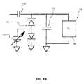
- FIG. 8Bshows another alternate schematic of a circuit board matching circuit with a varactor
- FIG. 9shows a replaceable tip matching circuit and joint
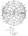
- FIG. 10Ashows a Smith chart and schematic for matching the load of a surgical tip with a source impedance using capacitors
- FIG. 10Bshows a Smith chart and schematic for matching the load of a surgical tip with a source impedance using a capacitor and a coaxial cable;
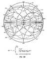
- FIG. 10Cshows a Smith chart and schematic for matching the load of a surgical tip with a source impedance using capacitors and an inductor
- FIG. 10Dshows a Smith chart and schematic for matching the load of a surgical tip with a source impedance using a capacitor and transformer
- FIG. 11Ashows a perspective view of a thermal surgical tool system
- FIG. 11Bshows a perspective view of an alternate embodiment of a thermal surgical tool system
- FIG. 12shows a diagram of a thermal surgical tool system
- FIG. 13Ashows a thermal surgical tool system with heat prevention terminals, heat sink, and wireless communication devices
- FIG. 13Bshows a thermal surgical tool system with an impedance matching network
- FIG. 14shows a close-up, side cross-sectional view of a single layer ferromagnetic coated conductor tip in accordance with one aspect of the present invention
- FIG. 15shows a close-up, side cross-sectional view of a single layer ferromagnetic coated conductor tip with a thermal insulator in accordance with one aspect of the present invention
- FIG. 16Ashows a close-up view of ferromagnetic coated conductor surgical tool tip with a loop geometry in accordance with one aspect of the present invention
- FIG. 16Bshows a close-up view of a ferromagnetic coated conductor surgical tool tip with a generally square geometry in accordance with one aspect of the present invention
- FIG. 16Cshows a close-up view of a ferromagnetic coated conductor surgical tool tip with a pointed geometry
- FIG. 16Dshows a close-up view of a ferromagnetic coated conductor surgical tool tip with an asymmetrical loop geometry
- FIG. 16Eshows a close-up view of a ferromagnetic coated conductor surgical tool tip with a hook geometry in which the concave portion may be used for therapeutic effect, including cutting;
- FIG. 16Fshows a close up view of a ferromagnetic coated conductor surgical tool tip with a hook geometry in which the convex portion may be used for therapeutic effect, including cutting;
- FIG. 16Gshows a close up view of a ferromagnetic coated conductor surgical tool tip with an angled geometry
- FIG. 17shows a cut-away view of a retracted snare
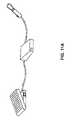
- FIG. 18Ashows a side view of an extended snare
- FIG. 18Bshows an alternate embodiment of an extended snare
- FIG. 19Ashows a close-up view of a ferromagnetic coated conductor surgical tool with a loop geometry and array of coatings
- FIG. 19Bshows a close up view of a ferromagnetic coated conductor surgical tool with an alternate hook geometry and array of coatings
- FIG. 20shows a cut-away view of a retracted snare with an array of coatings
- FIG. 21shows a side view of an extended snare with a array of coatings
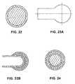
- FIG. 22shows an axial cross-sectional view of a single layer ferromagnetic coated conductor surgical tool in the ferromagnetic-coated region
- FIG. 23Ashows a perspective view of a multi-layer ferromagnetic coated conductor surgical tool tip
- FIG. 23Bshows a side cross-sectional view of a multi-layer ferromagnetic coated conductor surgical tool tip shown in 23 A;
- FIG. 24shows an axial cross-section of the multi-layer ferromagnetic coated conductor surgical tool tip shown in FIG. 23A ;
- FIG. 25shows a cross-sectional view of a flattened side cylindrical geometry ferromagnetic coated conductor showing electromagnetic lines of flux in accordance with one aspect of the present invention
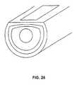
- FIG. 26shows a closed conductor tip in accordance with another aspect of the present invention.
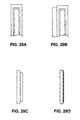
- FIG. 27Ashows a single edge ferromagnetic coated conductor surgical tip in accordance with one aspect of the invention
- FIG. 27Bshows a double edge ferromagnetic coated conductor surgical tip
- FIG. 27Cshows a three wire ferromagnetic coated conductor surgical tip
- FIG. 27Dshows a receptacle for the tips shown in FIGS. 27A through 27C ;
- FIG. 28Ashows a normally cold cutting scalpel with alternate inductive ferromagnetic thermal function
- FIG. 28Bshows an alternate embodiment of a normally cold cutting scalpel with alternate inductive ferromagnetic thermal function
- FIG. 29Ashows a thermal surgical tool with a spatula shaped geometry
- FIG. 29Bshows a thermal surgical tool with a spatula shaped geometry in a forceps configuration
- FIG. 29Cshows a top view of the thermal surgical tool of FIG. 29A with the ferromagnetic coated conductor upon the primary geometry
- FIG. 29Dshows a top view of the thermal surgical tool of FIG. 29A with the ferromagnetic coated conductor embedded within the primary geometry;
- FIG. 30Ashows a thermal surgical tool with a ball shaped geometry and horizontal winding
- FIG. 30Bshows an alternate embodiment of a thermal surgical tool with a ball shaped geometry and horseshoe configuration
- FIG. 30Cshows an alternate embodiment of a thermal surgical tool with a ball shaped geometry and vertical orientation
- FIG. 31Ashows a thermal surgical tool with a pointed geometry
- FIG. 31Bshows a thermal surgical tool with a pointed geometry in a forceps configuration
- FIG. 31Cshows a thermal surgical tool having two different activateable thermal zones
- FIG. 32Ashows a perspective view of a catheter having a coil of ferromagnetic coated conductor disposed around the tip of the catheter;
- FIG. 32Bshows a perspective view of a ferromagnetic coated conductor surgical catheter tip
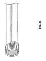
- FIG. 33shows a side view of an alternate embodiment of an ferromagnetic coated conductor surgical catheter tip
- FIG. 34shows an alternate embodiment of a ferromagnetic coated conductor surgical tip disposed within an endoscope
- FIG. 35shows a tissue ablation tool
- FIG. 36shows a multi-mode surgical tool with monopolar and thermal modalities
- FIG. 37Ashows a multi-mode tissue ablation tool within a metastasis in tissue, such as in a liver
- FIG. 37Bshows a close-up the ablating probe of FIG. 37A ;
- FIG. 37Cshows a close-up of an ablating probe with a sensor
- FIG. 37Dshows a close-up of a multiple tip ablating probe
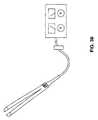
- FIG. 38shows a multi-mode surgical tool with bipolar and thermal modalities
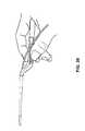
- FIG. 39shows a side view of multi-mode forceps
- FIG. 40Ashows a close-up of an alternate embodiment of forceps tips
- FIG. 40Bshows a diagram of a coated forceps tip
- FIG. 41Ashows a multi-mode surgical tool with thermal and ultrasonic modalities
- FIG. 41Bshows a multi-mode surgical tool with thermal and ultrasonic modalities with a hook primary geometry
- FIG. 41Cshows a multi-mode surgical tool with thermal and ultrasonic modalities with a sensor
- FIG. 41Dshows a multi-mode surgical tool with thermal and ultrasonic modalities with a second tip
- FIG. 42shows a multi-mode surgical tool with thermal and ultrasonic modalities with aspiration/irrigation and sensor.
- FIG. 43shows a thermal spectrum as related to tissue effects.
- a power source 20provides power which is delivered to the surgical handpiece 30 through a transmission line 40 .
- the power source 20may be impedance matched to the handpiece 30 equivalent load. More specifically, the power source 20 may be impedance matched to the transmission line 40 , which may be impedance matched to the surgical handpiece 30 . Therefore a matching circuit (also known as a network) may be used to match the power source to the load.
- a thermal element 50such as a ferromagnetic element, may form the active portion of the load.
- the thermal elementmay have little resistance.
- a matching circuitmay be used to match the impedance of the power source to the load of the thermal element.
- inductors and/or coaxial cablesmay be used to complete a matching circuit with the thermal element.
- thermal surgical toolswhich have been designed which may incorporate the principles of the present invention. Some such devices are disclosed in U.S. Publication Nos.
- FIG. 3a schematic of an equivalent circuit 60 which may be used with a surgical element 70 is shown.
- the impedance of the surgical element 70is designated as Z E .
- the matching networksmay be completed with a matching circuit 90 .
- Each matching circuitmay depend on the surgical element type, including chemical composition, geometry and physical properties. While a surgical element may be matched empirically, often times, a circuit may be monitored for a standing wave ratio (SWR) at a desired frequency, such as a voltage standing wave ratio (VSWR) and adjustments made to the matching network based on the SWR.
- SWRstanding wave ratio
- VSWRvoltage standing wave ratio
- a surgical element 70may be matched with a series capacitance 100 of between 10 pF and 300 pF and a parallel capacitance 110 of between 100 pF and 600 pF. More preferably, the element may be matched with a series capacitance of between 55 pF and 80 pF and a parallel capacitance of between 270 pF and 400 pF.
- the transmission line 40( FIG. 2 ) may be a 50 ohm coaxial cable.
- FIG. 4a chart 120 of standing wave ratio to frequency is shown. As SWR is minimized 125 , power transfer is increased. In some cases, a SWR ratio of 1:1 may be desired with maximum power transfer at the target frequency (F 0 ) 130 . Using the equivalent circuit of FIG. 3 , the series capacitance 100 and parallel capacitance 110 may be altered to minimize the SWR.
- a circuit board, flex board, etc.may be used as part of the matching circuit. After an initial matching circuit and load are assembled, the matching circuit may be adjusted for better power transfer near the end of the manufacturing process. This allows the system to be individually adjusted for component and manufacturing tolerances.
- one or more layers of circuit board conductor 140may be used as capacitors or other impedance matching circuit element.
- cut out portions 150 A ( FIG. 6A ), 150 B ( FIG. 6B ), 150 C ( FIG. 6B ) of the circuit boardare removed, the capacitance (or other electrical characteristics) of the circuit board conductor layer may be reduced or increased.
- the circuitmay be adjusted for some or all the manufacturing tolerances, and achieve a practically low SWR and better power transfer.
- a circuit board 155may have one or more layers 140 of circuit board conductor 140 , a fixed value portion 170 of the matching circuit, and a surgical element 70 .
- a layer or layers of circuit board conductor 140such as copper, may have intrinsic capacitance.
- the layer of conductor 140may be placed in series or parallel with a fixed value capacitor 160 as part of a fixed value portion 170 of the matching circuit.
- the circuit board 155may then be connected to a power source 20 ( FIG. 2 ) and SWR monitored as the circuit board 155 is adjusted.
- the layer of conductor 140may act as a variable capacitor.
- the layer of conductor 140may be used to alter the effective capacitance of a series capacitor 100 or parallel capacitor 110 (see FIG. 3 ) as it may be placed in parallel or series with a fixed capacitor.
- the fixed capacitancemay provide an initial value that may be effectively altered by the layer of conductor 140 to achieve a better SWR and consequently a better power transfer.
- the capacitance of the layer of conductor 140may be adjusted by removing portions 150 A of the circuit board 180 .
- SWRmay be monitored while removing portions 150 A of the circuit board 180 .
- SWRmay be monitored by a manufacturing system. When the system detects a minimum or acceptable SWR, the system may cease cutting the circuit board 180 . In other embodiments, the circuit board 180 may not be removed, but the layer of conductor 140 may be removed.
- the single plane circuit board 180may be assembled such that electrical components, including the surgical element, are attached.
- the circuit boardmay then be connected to a power source 20 ( FIG. 2 ). While SWR is monitored, a laser may remove portions of the layer of conductor 140 , which may include portions 150 A of the single plane circuit board 180 . When an acceptable SWR is reached, the system may stop removing portions of the layer of conductor 140 .
- the single plane circuit board 180may then move to further assembly.
- the circuit board 180may be used as a divider, such as in cooling applications. Therefore it may be desirable to cut longer portions 150 A′ of smaller width than portions 150 A with larger width.
- FIG. 6Ba diagram of a two layer circuit board 190 matching circuit is shown.
- an upper layer 200 A and lower layer 200 Bmay be used to alter the effective capacitance of a series capacitor 100 and parallel capacitor 110 (see FIG. 3 ) as the upper layer 200 A and lower layer 200 B may be placed in parallel or series with a fixed capacitor.
- both the effective series capacitance 100 and effective parallel capacitance 110may be adjusted.
- SWRmay be monitored as the upper layer 200 A is adjusted by forming the cut-out portion 150 B, and lower layer 200 B may be adjusted by the cut-out portion 150 C.
- the systemmay stop removing material from upper layer 200 A and/or lower layer 200 B.
- the upper layer 200 A and lower layer 200 Bmay be used to modify fixed capacitors 160 .
- circuit board conductor 140which combine a circuit board conductor 140 with other discrete circuit elements (e.g., capacitors), other embodiments may be implemented which rely solely on circuit board conductors 140 . Also, although embodiments of the circuit board conductor 140 are described as being implemented on a circuit board 150 , other types of flexible or rigid circuit substrates may be used.
- a conductor 140 acting as a capacitormay include an upper plate formed by a conductive circuit board layer, a dielectric formed by an insulating circuit board layer, and a lower plate formed by another conductive circuit board layer.
- more than two planes or layersmay be used in the circuit by providing areas that may be removed to adjust different planes/layers. In some cases, it may be desirable to have overlap in the planes, so that more than one capacitance may be altered by a single cut.
- FIG. 7shows a schematic of one embodiment of a circuit board matching circuit.
- Fixed capacitancessuch as series capacitance 100 and parallel capacitance 110 may be altered by the capacitances of upper layer 200 A and lower layer 200 B.
- the capacitancesallow the manufacturer to adjust the impedance matching circuit after the circuit has been constructed.
- surgical element impedance 80 and fixed capacitancesmay have manufacturing tolerances, the circuit may be tuned for better power transfer from a power source 20 ( FIG. 2 ) to surgical element 70 .
- This ability to tune the circuitsis similar, in some aspects, to using a variable capacitor.
- the capacitances 150 A that are adjusted by the manufacturermay be referred to as variable capacitances, although the variability is achieved through irreversible physical alterations.
- Series capacitance 100may be altered by the upper layer 200 A variable capacitance. As the capacitors are in parallel, their effect is additive. Therefore series capacitance 100 may be a minimum value which may be added upon by upper layer 200 A.
- parallel capacitance 110may be altered by the lower layer 200 B variable capacitance. As the capacitors are in parallel, their effect is additive. Therefore parallel capacitance 110 may be a minimum value which may be added upon by lower layer 200 B.
- either planemay modify either series or parallel capacitance by adjusting the circuit layout.
- the upper layer 200 Amay instead modify the parallel capacitance 110
- the lower layer 200 Bmay instead modify the series capacitance 100 .
- the layers 200 A and 200 Bmay be placed side by side or in any other desired configuration.
- FIG. 8Aan alternate schematic of a circuit board matching circuit is shown.
- the upper layer 200 A and lower layer 200 Bmay be installed in series or parallel with the series capacitance 100 and parallel capacitance 110 .
- the effective capacitancewill be smaller than either of the capacitances in series. Therefore, the series capacitance 100 and/or the parallel capacitance 110 may be chosen as a maximum amount to be adjusted downward by the corresponding variable layer capacitance.
- a varactor diodemay be used to adjust the apparent parallel capacitance 110 in a matching network.
- a variable voltage supply 112may cause the varactor diodes 114 to increase or decrease their depletion region size, changing the functional capacitance of the devices, which in turn additively changes the total capacitance of parallel capacitor 110 and the varactor diodes 114 .
- the voltage supply 112may be a fixed reference from a voltage divider network or regulated supply, driven by a digital to analog converter, an operation amplifier, or any other mechanism especially those which may adjust the voltage as part of an open or closed feedback loop. It will also be apparent to those skilled in the art that series capacitor 100 can be adjusted by a similar manner.
- a varactor diode 114may be substituted with a number of other types of devices such as rectifying diodes, which exhibit the same behavior as they are biased with an electric potential.
- the varactor diode 114may provide for a self-tuning surgical tip.
- a replaceable tip with matching circuit 215 and joint 205is shown.
- a replaceable tip with matching circuit 215may be connected to a handle body through a joint 205 .
- the matching circuit 215may contain a series capacitance 100 and parallel capacitance 110 .
- Electronically controlled capacitors 220 A, 220 Bmay be used to adjust the effective series and parallel capacitance for impedance matching.
- the electronically controlled capacitor values 220 A, 220 Bmay be set at manufacturing. After assembly of the replaceable tip electronics, the replaceable tip may be connected to a power source 20 ( FIG. 2 ). Electronically controlled capacitors may be adjusted until an acceptable SWR or near minimum SWR has been obtained. The electronically controlled capacitors may then have their settings stored with the matching circuit 215 , as described in more detail.
- Storing settings or controlling components of the matching circuitmay be accomplished through multiple methods.
- a processor 230may store the settings in non-volatile memory.
- fusesmay be used, such that by “blowing” a fuse, or rendering it inactive, a different setting is stored.
- circuit tracesmay be joined, such that each joining of a trace causes a different setting to be stored.
- a processor 230may monitor the SWR and adjust the electronically controlled capacitors. It may be desirable to have an active method of minimizing the SWR. By actively monitoring SWR, a system may be operable over more than a narrow frequency band. Thus, if different frequencies are desirable in different instances, an operator may choose the most effective frequency and the matching circuit 215 may automatically match the new impedance of the source, line and/or load.
- the sensor 232may monitor SWR and the information gathered by the sensor 232 may be used to adjust controllable capacitors, controllable inductors, controllable resistors, and/or other controllable components which might make up the matching circuit 215 according to principles discussed herein.
- a matching circuitmay be made more useful over a larger range of devices by including variable inductance, capacitance and/or resistance in the matching circuit. The matching circuit may thus be able to accommodate more surgical elements and/or more frequencies.
- the sensor 232may monitor SWR or another indicator which provides information regarding the efficiency of power transfer from a power source to the surgical instrument.
- the circuitmay be adjusted so that power transfer is improved or maximized.
- the matching circuitmay attempt to make adjustments to achieve SWR of 1:1 that may provide a desired response of better power transfer to the surgical element.
- the circuitmay use variable inductors, capacitors, transformers, transmission lines, resistors, and/or combinations of the foregoing to accomplish this goal.
- the overall goal of the present inventionis to provide for tuning of a thermal surgical instrument by transforming the impedance of a load, for example the load of a thermal element such as a ferromagnetic tip, to match that of a transmission line connecting a power source to the thermal element.
- a loadfor example the load of a thermal element such as a ferromagnetic tip
- the transmission line which carries the RF current from a power source to a surgical handpiecemay be 50 ohms.
- the thermal element, such as a ferromagnetic tipmay have a load of, for example, 2+i18 ohms.
- componentssuch as capacitors, coaxial cables, varactors, and sometimes more inductors may be used.
- a Smith chartmay be used to determine which components will make up the matching circuit.
- the Smith chartis plotted on the complex reflection coefficient plane in two dimensions and may be scaled in normalized impedance.
- the Smith charthas circumferential scaling in wavelengths and degrees.
- the wavelengths scaleis used in distributed component problems and represents the distance measured along the transmission line connected between the generator or source and the load to the point under consideration.
- the degrees scalerepresents the angle of the voltage reflection coefficient at that point.
- FIGS. 10A-10Dshow several examples of how one might transform the impedance of the load of a surgical tip of the present invention. It will be appreciated that there are a variety methods, other than using a Smith chart, which may be used to design a matching circuit of the present invention. Furthermore, those skilled in the art will appreciate that examples shown in FIGS. 10A-10D are not exhaustive of how the load may be matched to the characteristic impedance of a transmission line.
- FIG. 10Athere is shown a Smith chart having a normalized impedance of 50 ohms for designing a matching circuit for a transmission line having a characteristic impedance of 50 ohms.
- transmission lines having different characteristic impedance valuesmay be used with a thermal surgical instrument of the present invention, however, for ease of illustration the Smith chart discussed herein all have normalized impedance of 50 ohms.
- FIG. 10Aillustrates how capacitors may be used to transform the load of a surgical tip 250 to match the source impedance of a transmission line 260 .
- the load of the surgical tip 250is 2+i18 ohms.
- Capacitors connected in series and parallelmay be used to transform the load of the surgical to about 50+i0.0 ohms.
- the Smith chartmay be used to determine the proper capacitance to match the load 250 to the characteristic impedance of the transmission line.
- the load 250may be matched using a series capacitance 280 of about 52 pF and a parallel capacitance 270 of about 179 pF.
- a schematic 290 of the matching circuitis also shown in FIG. 10A .
- FIG. 10Billustrates how a length of coaxial cable and capacitors may be used match the load of a surgical tip 250 with a source impedance 260 .
- a series capacitance 280 of about 49 pF and a coaxial cable 270may be used to transform the load 2+i18 of the surgical tip 250 to about 50+i0.0 so that it substantially matches the source impedance 260 .
- a schematic 320 of such a matching circuitis also shown in FIG. 10B .
- FIG. 10Cillustrates how capacitors and inductors may be used match the load of a surgical tip 250 with a source impedance 260 .
- a series capacitance 350 of about 79 pF, a parallel capacitance 340 of about 235 pF, and an inductance 330 of about 35 nHmay be used to transform the load 2+i5 of the surgical tip 250 to about 50+i0.0 so that it substantially matches the source impedance 260 .
- the matching circuit of FIG. 10Cmay be particularly useful with surgical tips which have very low impedance.
- a schematic 360 of such a matching circuitis also shown in FIG. 10C .
- FIG. 10Dillustrates how a capacitor and transformer may be used to match the load of a surgical tip 250 with a source impedance 260 .
- a series capacitance 380 of about 31 pF and a transformer having a primary to secondary turn ratio of 1:5.00may be used to transform the load 2+i5 of the surgical tip 250 to about 50+i0.0 so that it substantially matches the source impedance 260 .
- a schematic 390 of such a matching circuitis also shown in FIG. 10D .
- FIGS. 11A to 42show various embodiments of surgical elements and handpieces that may benefit from an impedance matching circuit using the techniques and construction described above.
- FIGS. 11A to 13Ba surgical handpiece is shown with a power source, control and handpiece.
- the surgical elementmay be a ferromagnetic covered conductor.
- FIG. 13Bshows an autotransformer, which may be another way of matching the load of the thermal element of a surgical tool to a power source.
- FIGS. 14 to 33various tip geometries are shown. Each tip configuration may require different base impedance matching circuit component values as well as individual adjustments due to manufacturing tolerances. Tip configurations such as geometry, thicknesses of layers, composition, and length, may all require different matching circuit component values.
- the impedance matching circuitsmay be used with different surgical tools and/or modalities such as catheters ( FIG. 34 ), thermal surgical tools ( FIG. 35 ), mono-polar electrosurgical tools ( FIG. 36 ), bipolar electrosurgical tools ( FIG. 38 ), ultra-sonic surgical tools ( FIG. 41A ), and multi-mode surgical tools that may combine multiple surgical modalities into one instrument, such as a thermal and bipolar surgical modality.
- different surgical tools and/or modalitiessuch as catheters ( FIG. 34 ), thermal surgical tools ( FIG. 35 ), mono-polar electrosurgical tools ( FIG. 36 ), bipolar electrosurgical tools ( FIG. 38 ), ultra-sonic surgical tools ( FIG. 41A ), and multi-mode surgical tools that may combine multiple surgical modalities into one instrument, such as a thermal and bipolar surgical modality.
- FIG. 43a thermal spectrum as related to tissue effects is shown.
- efficient power transfersuch as may be achieved with a correctly adjusted matching circuit
- a smaller power sourcemay be used to achieve desired tissue effects than would be required with an inefficient power transfer.
Landscapes
- Health & Medical Sciences (AREA)
- Engineering & Computer Science (AREA)
- Surgery (AREA)
- Life Sciences & Earth Sciences (AREA)
- Medical Informatics (AREA)
- Molecular Biology (AREA)
- Nuclear Medicine, Radiotherapy & Molecular Imaging (AREA)
- Plasma & Fusion (AREA)
- Biomedical Technology (AREA)
- Heart & Thoracic Surgery (AREA)
- Physics & Mathematics (AREA)
- Otolaryngology (AREA)
- Animal Behavior & Ethology (AREA)
- General Health & Medical Sciences (AREA)
- Public Health (AREA)
- Veterinary Medicine (AREA)
- Manufacturing & Machinery (AREA)
- Microelectronics & Electronic Packaging (AREA)
- Surgical Instruments (AREA)
- Amplifiers (AREA)
Abstract
Description
The present application claims the benefit of U.S. Provisional Patent Application Ser. No. 61/473,722, filed Apr. 8, 2011, which is incorporated herein by reference in its entirety.
The present invention relates to power transfer. More specifically, the present invention relates to optimum power transfer from a power source to a thermal surgical instrument.
Circuits may be designed with maximum voltage to load, maximum power to load or, sometimes, no thought to power or voltage transfer. In many situations, maximum power transfer is desirable, as it provides maximum power to the load. It is believed that maximum power transfer may be achieved by matching the impedance of the source to the load (and any intermediate lines or components). Circuits may use a matching network on the source side and load side (seeFIG. 1A ) or on one side only.
In general, impedance has a complex value; this means that loads (symbolized as Z) generally have a resistance component (symbolized as R) which forms the real part of Z and a reactance component (symbolized as X) which forms the imaginary part of Z. Power transfer theory dictates that for maximum power to be transferred, the source impedance (ZS) should equal the complex conjugate of the load impedance (ZL) such that the following equation holds true: RS+jXS=RL−jXL(seeFIG. 1B ). As reactance X is variable with frequency, the matching network is generally tuned to one frequency.
Matching the load to the characteristic impedance (Z0) of the transmission line allows reflectionless matching, minimizing reflections from the load. Thus, a transmission line connecting the source and load together would ideally be the same impedance: ZL=Z0=ZS.
While in an ideal world, Z1, Z0and ZLwould be immutable and the same for every product produced, the impedances may be variable due to tolerances and design in manufacturing. Therefore, there is a need to customize each circuit to match impedances in a cost efficient manner.
It is an object of the present invention to provide an improved impedance matching circuit for a thermal surgical instrument.
According to one aspect of the invention, a conductive layer may be used as a variable capacitor. The conductive layer may be formed as part of a circuit board, flex board, etc. As the system monitors standing wave ratio, portions of the circuit board may be removed until a minimum of the standing wave ratio is obtained. Two conductive layers may be used to provide adjustments for the series capacitance and parallel capacitance. Removing part of a conductive layer from one side of the circuit board may adjust the series capacitance, while removing part of a conductive layer from the other side may adjust the parallel capacitance.
According to another aspect of the invention, a surgical tip may contain a matching circuit or network. The surgical tip may comprise different geometries having different characteristic impedance. Additionally, due to variations in fabrication, any two similar tips may have slightly different characteristic impedances. Thus each tip may be individually configured using the matching circuit. The surgical tips may be attachable to a handpiece which receives electrical energy from a power source via a transmission line having characteristic impedances that match the impedance of the surgical tip to achieve substantially maximum power transfer.
According to another aspect of the invention, standing wave ratio may be monitored to determine if the system has encountered a failure or a limit.
According to another aspect of the invention, a capacitor and/or inductor, such as an electronically controlled capacitor and/or inductor may be used in tuning the circuit. In one embodiment, the capacitor and/or inductor value may be set at manufacturing as part of the impedance matching setting. In another embodiment, the matching circuit may contain a processor that monitors SWR and adjusts an electronically controlled capacitor and/or inductor to minimize SWR.
According to another aspect of the invention, a coaxial cable having a characteristic impedance may be used in tuning the circuit.
According to still another aspect of the invention, inductors, transformers, resistors, varactors, coaxial cables, and/or combinations thereof may be used in tuning the circuit.
These and other aspects of the present invention are realized in an impedance matching circuit as shown and described in the following figures and related description.
Various embodiments of the present invention are shown and described in reference to the numbered drawings wherein:
It will be appreciated that the drawings are illustrative and not limiting of the scope of the invention which is defined by the appended claims. The embodiments shown accomplish various aspects and objects of the invention. It is appreciated that it is not possible to clearly show each element and aspect of the invention in a single figure, and as such, multiple figures are presented to separately illustrate the various details of the invention in greater clarity. Thus, multiple figures may be used to show a particular aspect of the invention. Similarly, not every embodiment need accomplish all advantages of the present invention.
The invention and accompanying drawings will now be discussed in reference to the numerals provided therein so as to enable one skilled in the art to practice the present invention. The drawings and descriptions are exemplary of various aspects of the invention and are not intended to narrow the scope of the appended claims.
Turning now toFIG. 2 , asurgical system 10 is shown. Apower source 20 provides power which is delivered to thesurgical handpiece 30 through atransmission line 40. As maximum power transfer may be desired, thepower source 20 may be impedance matched to thehandpiece 30 equivalent load. More specifically, thepower source 20 may be impedance matched to thetransmission line 40, which may be impedance matched to thesurgical handpiece 30. Therefore a matching circuit (also known as a network) may be used to match the power source to the load.
In the surgical handpiece shown, athermal element 50, such as a ferromagnetic element, may form the active portion of the load. The thermal element may have little resistance. A matching circuit may be used to match the impedance of the power source to the load of the thermal element. Alternatively, inductors and/or coaxial cables (or other suitable components as explained in more detail below) may be used to complete a matching circuit with the thermal element. There are multiple thermal surgical tools which have been designed which may incorporate the principles of the present invention. Some such devices are disclosed in U.S. Publication Nos. 2010-0268207, 2010-0268214, 2010-0268208, 2010-0268209, 2010-0268215, 2010-0268205, 2010-0268210, 2010-0268212, 2010-0268213, 2010-0268211, 2010-0268216, 2010-0268206, all of which are expressly incorporated herein.
Turning now toFIG. 3 , a schematic of anequivalent circuit 60 which may be used with asurgical element 70 is shown. The impedance of thesurgical element 70 is designated as ZE. In the case of somesurgical elements 70 with some resistance andinductive reactance 80, the matching networks may be completed with amatching circuit 90. Each matching circuit may depend on the surgical element type, including chemical composition, geometry and physical properties. While a surgical element may be matched empirically, often times, a circuit may be monitored for a standing wave ratio (SWR) at a desired frequency, such as a voltage standing wave ratio (VSWR) and adjustments made to the matching network based on the SWR. According to one aspect of the invention, asurgical element 70 may be matched with aseries capacitance 100 of between 10 pF and 300 pF and aparallel capacitance 110 of between 100 pF and 600 pF. More preferably, the element may be matched with a series capacitance of between 55 pF and 80 pF and a parallel capacitance of between 270 pF and 400 pF. The transmission line40 (FIG. 2 ) may be a 50 ohm coaxial cable.
Turning now toFIG. 4 , achart 120 of standing wave ratio to frequency is shown. As SWR is minimized125, power transfer is increased. In some cases, a SWR ratio of 1:1 may be desired with maximum power transfer at the target frequency (F0)130. Using the equivalent circuit ofFIG. 3 , theseries capacitance 100 andparallel capacitance 110 may be altered to minimize the SWR.
Turning now toFIGS. 5 ,6A and6B, a circuit board, flex board, etc. may be used as part of the matching circuit. After an initial matching circuit and load are assembled, the matching circuit may be adjusted for better power transfer near the end of the manufacturing process. This allows the system to be individually adjusted for component and manufacturing tolerances.
More specifically, one or more layers ofcircuit board conductor 140 may be used as capacitors or other impedance matching circuit element. As cut outportions 150A (FIG. 6A ),150B (FIG. 6B ),150C (FIG. 6B ) of the circuit board are removed, the capacitance (or other electrical characteristics) of the circuit board conductor layer may be reduced or increased. Thus, after being built, the circuit may be adjusted for some or all the manufacturing tolerances, and achieve a practically low SWR and better power transfer.
As a general note, although many of the embodiments described herein describe using capacitances to implement a matching circuit, other circuit elements may be used in addition to or instead of the referenced capacitors. Indeed, in this example embodiment, which has a primarily inductive load, capacitive tuning is readily applicable. In cases where the load looks capacitive, an inductive matching circuit may be appropriate. Any combination of reactive elements may be used to match one load to another.
Turning now specifically toFIG. 5 , a diagram of an unaltered circuit board matching circuit is shown. At the end of manufacturing, acircuit board 155 may have one ormore layers 140 ofcircuit board conductor 140, a fixedvalue portion 170 of the matching circuit, and asurgical element 70. A layer or layers ofcircuit board conductor 140, such as copper, may have intrinsic capacitance. The layer ofconductor 140 may be placed in series or parallel with a fixedvalue capacitor 160 as part of a fixedvalue portion 170 of the matching circuit. Thecircuit board 155 may then be connected to a power source20 (FIG. 2 ) and SWR monitored as thecircuit board 155 is adjusted.
Turning now specifically toFIG. 6A , a diagram of a singleplane circuit board 180 matching circuit is shown. The layer ofconductor 140 may act as a variable capacitor. The layer ofconductor 140 may be used to alter the effective capacitance of aseries capacitor 100 or parallel capacitor110 (seeFIG. 3 ) as it may be placed in parallel or series with a fixed capacitor. By using the layer ofconductor 140 with a fixed capacitance, the fixed capacitance may provide an initial value that may be effectively altered by the layer ofconductor 140 to achieve a better SWR and consequently a better power transfer.
In the case of a single plane matching circuit, the capacitance of the layer ofconductor 140 may be adjusted by removingportions 150A of thecircuit board 180. SWR may be monitored while removingportions 150A of thecircuit board 180. For example, SWR may be monitored by a manufacturing system. When the system detects a minimum or acceptable SWR, the system may cease cutting thecircuit board 180. In other embodiments, thecircuit board 180 may not be removed, but the layer ofconductor 140 may be removed.
According to one aspect of the invention, the singleplane circuit board 180 may be assembled such that electrical components, including the surgical element, are attached. The circuit board may then be connected to a power source20 (FIG. 2 ). While SWR is monitored, a laser may remove portions of the layer ofconductor 140, which may includeportions 150A of the singleplane circuit board 180. When an acceptable SWR is reached, the system may stop removing portions of the layer ofconductor 140. The singleplane circuit board 180 may then move to further assembly.
According to another aspect of the invention, thecircuit board 180 may be used as a divider, such as in cooling applications. Therefore it may be desirable to cutlonger portions 150A′ of smaller width thanportions 150A with larger width.
Turning now toFIG. 6B , a diagram of a twolayer circuit board 190 matching circuit is shown. With a twolayer circuit board 190, anupper layer 200A andlower layer 200B may be used to alter the effective capacitance of aseries capacitor 100 and parallel capacitor110 (seeFIG. 3 ) as theupper layer 200A andlower layer 200B may be placed in parallel or series with a fixed capacitor. Thus, both theeffective series capacitance 100 and effectiveparallel capacitance 110 may be adjusted.
SWR may be monitored as theupper layer 200A is adjusted by forming the cut-outportion 150B, andlower layer 200B may be adjusted by the cut-outportion 150C. When the SWR is acceptable or is near a minimum, the system may stop removing material fromupper layer 200A and/orlower layer 200B. Thus, theupper layer 200A andlower layer 200B may be used to modify fixedcapacitors 160.
Although embodiments of matching circuits are described which combine acircuit board conductor 140 with other discrete circuit elements (e.g., capacitors), other embodiments may be implemented which rely solely oncircuit board conductors 140. Also, although embodiments of thecircuit board conductor 140 are described as being implemented on a circuit board150, other types of flexible or rigid circuit substrates may be used.
While circuit board layers or layers on a flex board have been discussed inFIGS. 5-6B , it should be recognized that it may be desirable to use multiple conductor layers in a multi-layer circuit board to create a single capacitance. For example, aconductor 140 acting as a capacitor may include an upper plate formed by a conductive circuit board layer, a dielectric formed by an insulating circuit board layer, and a lower plate formed by another conductive circuit board layer. Furthermore, it should be recognized that more than two planes or layers may be used in the circuit by providing areas that may be removed to adjust different planes/layers. In some cases, it may be desirable to have overlap in the planes, so that more than one capacitance may be altered by a single cut.
Similarly,parallel capacitance 110 may be altered by thelower layer 200B variable capacitance. As the capacitors are in parallel, their effect is additive. Thereforeparallel capacitance 110 may be a minimum value which may be added upon bylower layer 200B.
It should be recognized that either plane may modify either series or parallel capacitance by adjusting the circuit layout. Theupper layer 200A may instead modify theparallel capacitance 110, and thelower layer 200B may instead modify theseries capacitance 100. Likewise, thelayers
Turning now toFIG. 8A , an alternate schematic of a circuit board matching circuit is shown. It should be recognized that theupper layer 200A andlower layer 200B may be installed in series or parallel with theseries capacitance 100 andparallel capacitance 110. In the figure shown, the capacitances are related to their inverse such that the relation to the effective capacitance (Ceff) is 1/Ceff=1/C100+1/C200A. Thus, the effective capacitance will be smaller than either of the capacitances in series. Therefore, theseries capacitance 100 and/or theparallel capacitance 110 may be chosen as a maximum amount to be adjusted downward by the corresponding variable layer capacitance.
Turning now toFIG. 8B , a varactor diode may be used to adjust the apparentparallel capacitance 110 in a matching network. Avariable voltage supply 112 may cause thevaractor diodes 114 to increase or decrease their depletion region size, changing the functional capacitance of the devices, which in turn additively changes the total capacitance ofparallel capacitor 110 and thevaractor diodes 114. Thevoltage supply 112 may be a fixed reference from a voltage divider network or regulated supply, driven by a digital to analog converter, an operation amplifier, or any other mechanism especially those which may adjust the voltage as part of an open or closed feedback loop. It will also be apparent to those skilled in the art thatseries capacitor 100 can be adjusted by a similar manner. It will be further apparent to those skilled in the art that avaractor diode 114 may be substituted with a number of other types of devices such as rectifying diodes, which exhibit the same behavior as they are biased with an electric potential. Thus, to the extent that the variable voltage source is controlled to adjust based on operating characteristics of thesurgical tip 70, thevaractor diode 114 may provide for a self-tuning surgical tip.
Turning now toFIG. 9 , a replaceable tip with matchingcircuit 215 and joint205 is shown. A replaceable tip with matchingcircuit 215 may be connected to a handle body through a joint205. Similar to the circuit seen inFIG. 7 , thematching circuit 215 may contain aseries capacitance 100 andparallel capacitance 110. Electronically controlledcapacitors
The electronically controlled capacitor values220A,220B may be set at manufacturing. After assembly of the replaceable tip electronics, the replaceable tip may be connected to a power source20 (FIG. 2 ). Electronically controlled capacitors may be adjusted until an acceptable SWR or near minimum SWR has been obtained. The electronically controlled capacitors may then have their settings stored with thematching circuit 215, as described in more detail.
Storing settings or controlling components of the matching circuit may be accomplished through multiple methods. According to one aspect of the invention, aprocessor 230 may store the settings in non-volatile memory. Alternatively, fuses may be used, such that by “blowing” a fuse, or rendering it inactive, a different setting is stored. According to another aspect, circuit traces may be joined, such that each joining of a trace causes a different setting to be stored.
In another embodiment, aprocessor 230 may monitor the SWR and adjust the electronically controlled capacitors. It may be desirable to have an active method of minimizing the SWR. By actively monitoring SWR, a system may be operable over more than a narrow frequency band. Thus, if different frequencies are desirable in different instances, an operator may choose the most effective frequency and thematching circuit 215 may automatically match the new impedance of the source, line and/or load.
According to one aspect of the present invention, thesensor 232 may monitor SWR and the information gathered by thesensor 232 may be used to adjust controllable capacitors, controllable inductors, controllable resistors, and/or other controllable components which might make up thematching circuit 215 according to principles discussed herein. In some embodiments, a matching circuit may be made more useful over a larger range of devices by including variable inductance, capacitance and/or resistance in the matching circuit. The matching circuit may thus be able to accommodate more surgical elements and/or more frequencies.
Thesensor 232 may monitor SWR or another indicator which provides information regarding the efficiency of power transfer from a power source to the surgical instrument. Thus, when the indicator, such as SWR, suggests that power is being lost in transmission to the surgical instrument, the circuit may be adjusted so that power transfer is improved or maximized. In the case of SWR, the matching circuit may attempt to make adjustments to achieve SWR of 1:1 that may provide a desired response of better power transfer to the surgical element. The circuit may use variable inductors, capacitors, transformers, transmission lines, resistors, and/or combinations of the foregoing to accomplish this goal.
The overall goal of the present invention is to provide for tuning of a thermal surgical instrument by transforming the impedance of a load, for example the load of a thermal element such as a ferromagnetic tip, to match that of a transmission line connecting a power source to the thermal element. For example, the transmission line which carries the RF current from a power source to a surgical handpiece may be 50 ohms. The thermal element, such as a ferromagnetic tip may have a load of, for example, 2+i18 ohms. To transform the inductive load of the thermal element to a 50+i0.0 ohm load to match the characteristic impedance of the transmission line, components such as capacitors, coaxial cables, varactors, and sometimes more inductors may be used.
A Smith chart may be used to determine which components will make up the matching circuit. The Smith chart is plotted on the complex reflection coefficient plane in two dimensions and may be scaled in normalized impedance. The Smith chart has circumferential scaling in wavelengths and degrees. The wavelengths scale is used in distributed component problems and represents the distance measured along the transmission line connected between the generator or source and the load to the point under consideration. The degrees scale represents the angle of the voltage reflection coefficient at that point.
For example a Smith chart having a normalized impedance of 50 ohms may be used to design a matching circuit for matching the impedance of a load with the impedance of a transmission line having a characteristic impedance of 50 ohms.FIGS. 10A-10D show several examples of how one might transform the impedance of the load of a surgical tip of the present invention. It will be appreciated that there are a variety methods, other than using a Smith chart, which may be used to design a matching circuit of the present invention. Furthermore, those skilled in the art will appreciate that examples shown inFIGS. 10A-10D are not exhaustive of how the load may be matched to the characteristic impedance of a transmission line.
Turning now toFIG. 10A , there is shown a Smith chart having a normalized impedance of 50 ohms for designing a matching circuit for a transmission line having a characteristic impedance of 50 ohms. It will be appreciated that transmission lines having different characteristic impedance values may be used with a thermal surgical instrument of the present invention, however, for ease of illustration the Smith chart discussed herein all have normalized impedance of 50 ohms.FIG. 10A illustrates how capacitors may be used to transform the load of asurgical tip 250 to match the source impedance of atransmission line 260. The load of thesurgical tip 250 is 2+i18 ohms. Capacitors connected in series and parallel may be used to transform the load of the surgical to about 50+i0.0 ohms. The Smith chart may be used to determine the proper capacitance to match theload 250 to the characteristic impedance of the transmission line. For example, theload 250 may be matched using aseries capacitance 280 of about 52 pF and aparallel capacitance 270 of about 179 pF. A schematic290 of the matching circuit is also shown inFIG. 10A .
Turning now toFIGS. 11A to 13B , a surgical handpiece is shown with a power source, control and handpiece. The surgical element may be a ferromagnetic covered conductor.FIG. 13B shows an autotransformer, which may be another way of matching the load of the thermal element of a surgical tool to a power source.
Turning now toFIGS. 14 to 33 , various tip geometries are shown. Each tip configuration may require different base impedance matching circuit component values as well as individual adjustments due to manufacturing tolerances. Tip configurations such as geometry, thicknesses of layers, composition, and length, may all require different matching circuit component values.
Turning now toFIGS. 34 to 42 , various surgical tools are shown. The impedance matching circuits may be used with different surgical tools and/or modalities such as catheters (FIG. 34 ), thermal surgical tools (FIG. 35 ), mono-polar electrosurgical tools (FIG. 36 ), bipolar electrosurgical tools (FIG. 38 ), ultra-sonic surgical tools (FIG. 41A ), and multi-mode surgical tools that may combine multiple surgical modalities into one instrument, such as a thermal and bipolar surgical modality.
Turning now toFIG. 43 , a thermal spectrum as related to tissue effects is shown. With efficient power transfer, such as may be achieved with a correctly adjusted matching circuit, a smaller power source may be used to achieve desired tissue effects than would be required with an inefficient power transfer.
There is thus disclosed an improved impedance matching circuit. It will be appreciated that numerous changes may be made to the present invention without departing from the scope of the claims.
Claims (21)
1. A thermal surgical instrument comprising:
a thermal element configured to generate thermal energy in response to an electrical signal, the thermal element comprising a ferromagnetic material disposed on an electrical conductor; and
a matching circuit electrically connected to the thermal element;
wherein the matching circuit, in combination with the thermal element, has an input impedance.
2. The thermal surgical instrument ofclaim 1 , wherein the thermal surgical instrument is connectable to a power source, and wherein the input impedance matches the output impedance of the power source.
3. The thermal surgical instrument ofclaim 1 , wherein the thermal surgical instrument is connectable to a power source via a transmission line, and wherein the input impedance matches the impedance of the transmission line.
4. The thermal surgical instrument ofclaim 1 , further comprising a sensor to monitor an indicator of efficiency of power transfer to the thermal surgical instrument.
5. The thermal surgical instrument ofclaim 1 , wherein the input impedance is adjustable.
6. The thermal surgical instrument ofclaim 5 , wherein the input impedance is electronically adjustable.
7. The thermal surgical instrument ofclaim 1 , wherein the matching circuit comprises at least one component selected from the group of a capacitor, inductor, variable capacitor, variable inductor, transformer, coaxial cable, and varactor.
8. The thermal surgical instrument ofclaim 1 , further comprising a data storage unit to store a setting of the thermal surgical element.
9. The thermal surgical instrument ofclaim 8 , wherein the data storage unit is an EEPROM.
10. A thermal surgical instrument comprising:
a thermal element configured to generate thermal energy in response to an electrical signal; and
a matching circuit electrically connected to the thermal element;
wherein the matching circuit, in combination with the thermal element, has an input impedance; and
wherein the matching circuit further comprises a conductive layer disposed on a substrate, wherein at least a portion of the conductive layer is removable.
11. A method of matching an input impedance of a load of a thermal surgical instrument with an output impedance of a power source comprising the steps of:
selecting a thermal surgical tool having a thermal element and a circuit board;
disposing a component on the circuit board to form a matching circuit;
wherein the thermal element and the matching circuit comprise a load having an adjustable input impedance.
12. The method according toclaim 11 , further comprising measuring an indicator of the load and adjusting the component so that the adjustable input impedance is substantially equal to an output impedance of a transmission line connecting a power source to the thermal surgical instrument.
13. The method according toclaim 12 , wherein the component comprises a conductive layer, and wherein the method further comprises removing at least a portion of the conductive layer to adjust the input impedance.
14. The method according toclaim 12 , wherein components are adjusted electronically.
15. The method according toclaim 11 , further comprising disposing a second component on the board to form the matching circuit.
16. The method according toclaim 11 , wherein the indicator measured is the standing wave ratio on the transmission line caused by impedance mismatch interaction between the load and source, and wherein the component is adjusted such that the standard wave ratio is substantially 1:1.
17. The method according toclaim 11 , wherein the component is a varactor, and wherein the method further comprises controlling a voltage applied to the varactor to adjust the input impedance.
18. A method of manufacturing a thermal surgical instrument comprising the steps of:
selecting a surgical instrument comprising a thermal element;
disposing a matching circuit in electrical communication with the thermal element such that the matching circuit, in combination with the thermal element, has an input impedance and wherein the matching circuit comprises a conductive layer; and
adjusting the input impedance by removing at least a portion of the conductive layer so that it matches an output impedance of a power source.
19. The method according toclaim 18 , further comprising disposing a data storage unit on the thermal surgical instrument, wherein the data storage unit stores settings of the thermal surgical instrument.
20. The method according toclaim 18 , further comprising disposing a sensor on the thermal surgical element for monitoring an indicator of the thermal element.
21. A thermal surgical tool comprising:
a thermal element;
a circuit board having a component disposed thereon to form a matching circuit; and
wherein the thermal element and the matching circuit comprise a load having an adjustable input impedance.
Priority Applications (2)
| Application Number | Priority Date | Filing Date | Title |
|---|---|---|---|
| US13/441,860US8915909B2 (en) | 2011-04-08 | 2012-04-07 | Impedance matching circuit |
| US14/551,506US20150173822A1 (en) | 2011-04-08 | 2014-11-24 | Impedance Matching Circuit |
Applications Claiming Priority (2)
| Application Number | Priority Date | Filing Date | Title |
|---|---|---|---|
| US201161473722P | 2011-04-08 | 2011-04-08 | |
| US13/441,860US8915909B2 (en) | 2011-04-08 | 2012-04-07 | Impedance matching circuit |
Related Child Applications (1)
| Application Number | Title | Priority Date | Filing Date |
|---|---|---|---|
| US14/551,506ContinuationUS20150173822A1 (en) | 2011-04-08 | 2014-11-24 | Impedance Matching Circuit |
Publications (2)
| Publication Number | Publication Date |
|---|---|
| US20120259323A1 US20120259323A1 (en) | 2012-10-11 |
| US8915909B2true US8915909B2 (en) | 2014-12-23 |
Family
ID=46966666
Family Applications (2)
| Application Number | Title | Priority Date | Filing Date |
|---|---|---|---|
| US13/441,860Active2033-05-12US8915909B2 (en) | 2011-04-08 | 2012-04-07 | Impedance matching circuit |
| US14/551,506AbandonedUS20150173822A1 (en) | 2011-04-08 | 2014-11-24 | Impedance Matching Circuit |
Family Applications After (1)
| Application Number | Title | Priority Date | Filing Date |
|---|---|---|---|
| US14/551,506AbandonedUS20150173822A1 (en) | 2011-04-08 | 2014-11-24 | Impedance Matching Circuit |
Country Status (4)
| Country | Link |
|---|---|
| US (2) | US8915909B2 (en) |
| EP (1) | EP2704657A4 (en) |
| CA (1) | CA2868742A1 (en) |
| WO (1) | WO2013106036A2 (en) |
Cited By (8)
| Publication number | Priority date | Publication date | Assignee | Title |
|---|---|---|---|---|
| US9283023B2 (en) | 2011-06-13 | 2016-03-15 | Bovie Medical Corporation | Hand-held cautery device |
| US10045809B2 (en) | 2015-08-05 | 2018-08-14 | Terumo Cardiovascular Systems Corporation | Endoscopic vessel harvester with blunt and active dissection |
| US10117700B2 (en) | 2015-08-05 | 2018-11-06 | Terumo Cardiovascular Systems Corporation | Endoscopic vessel harvester with blunt and active ring dissection |
| US11365490B2 (en) | 2019-12-21 | 2022-06-21 | Covidien Lp | Thermal cutting elements, electrosurgical instruments including thermal cutting elements, and methods of manufacturing |
| US11529186B2 (en) | 2019-07-22 | 2022-12-20 | Covidien Lp | Electrosurgical forceps including thermal cutting element |
| US12048472B2 (en) | 2021-02-01 | 2024-07-30 | Covidien Lp | Electrosurgical instruments, jaw members thereof, and methods of manufacturing |
| US12251155B2 (en) | 2021-05-27 | 2025-03-18 | Covidien Lp | Methods for open dissection using sealing instrument |
| US12408970B2 (en) | 2020-04-02 | 2025-09-09 | Covidien Lp | Systems and methods for sealing and dissecting tissue using an electrosurgical forceps including a thermal cutting element |
Families Citing this family (13)
| Publication number | Priority date | Publication date | Assignee | Title |
|---|---|---|---|---|
| US9107666B2 (en) | 2009-04-17 | 2015-08-18 | Domain Surgical, Inc. | Thermal resecting loop |
| US9730749B2 (en) | 2009-04-17 | 2017-08-15 | Domain Surgical, Inc. | Surgical scalpel with inductively heated regions |
| US9131977B2 (en) | 2009-04-17 | 2015-09-15 | Domain Surgical, Inc. | Layered ferromagnetic coated conductor thermal surgical tool |
| US8932279B2 (en) | 2011-04-08 | 2015-01-13 | Domain Surgical, Inc. | System and method for cooling of a heated surgical instrument and/or surgical site and treating tissue |
| WO2013040255A2 (en) | 2011-09-13 | 2013-03-21 | Domain Surgical, Inc. | Sealing and/or cutting instrument |
| JP2015506729A (en) | 2011-12-06 | 2015-03-05 | ドメイン・サージカル,インコーポレーテッド | System and method for controlling power supply to a surgical instrument |
| JP5702326B2 (en)* | 2012-03-30 | 2015-04-15 | 富士フイルム株式会社 | Ultrasonic probe and ultrasonic diagnostic apparatus including the same |
| US10357306B2 (en) | 2014-05-14 | 2019-07-23 | Domain Surgical, Inc. | Planar ferromagnetic coated surgical tip and method for making |
| CN105832411B (en)* | 2016-01-25 | 2020-10-27 | 安进医疗科技(北京)有限公司 | Endoscope electrode system for electromagnetic knife operation |
| CN110311646A (en)* | 2019-06-28 | 2019-10-08 | 高斯贝尔数码科技股份有限公司 | A kind of adaptive matching method and system of microwave power source and reaction chamber |
| US20210244465A1 (en)* | 2020-02-07 | 2021-08-12 | Covidien Lp | Electrosurgical instruments and systems including thermal cutting elements |
| CN111544110B (en)* | 2020-05-06 | 2021-07-20 | 安进医疗科技(北京)有限公司 | Endoscopic surgery electrode assembly |
| CA3190840A1 (en) | 2020-09-02 | 2022-03-10 | Pulse Biosciences, Inc. | Universal handpiece for electrical treatment applicator |
Citations (262)
| Publication number | Priority date | Publication date | Assignee | Title |
|---|---|---|---|---|
| US300155A (en) | 1884-06-10 | stabr | ||
| US770368A (en) | 1904-09-20 | Surgical instrument | ||
| US1104053A (en) | 1912-09-28 | 1914-07-21 | Donald Henry Lea | Tool for uncapping honey and like purposes. |
| US1280052A (en) | 1916-12-18 | 1918-09-24 | Tiodolf Lidberg | Therapeutic instrument. |
| US1335987A (en) | 1919-05-27 | 1920-04-06 | Kienle | Dental instrument |
| US1366231A (en) | 1917-09-08 | 1921-01-18 | Kny Scheerer Corp | Sterilizable cautery |
| US1401104A (en) | 1920-03-15 | 1921-12-20 | Kruesheld Henry | Surgical instrument |
| US1794296A (en) | 1927-08-24 | 1931-02-24 | Mortimer N Hyams | Surgical instrument |
| US2027854A (en) | 1934-11-14 | 1936-01-14 | Gen Tire & Rubber Co | Tube splicer |
| US2050904A (en) | 1934-11-26 | 1936-08-11 | Trice Spencer Talley | Electric hemostat or cautery |
| US2120598A (en) | 1937-03-06 | 1938-06-14 | George H Beuoy | Electrical cutting instrument |
| US2250602A (en) | 1939-08-21 | 1941-07-29 | Paul W Pierce | Honey uncapping knife |
| US2278633A (en) | 1940-08-15 | 1942-04-07 | American Telephone & Telegraph | Temperature control apparatus |
| US2375154A (en) | 1943-10-07 | 1945-05-01 | Metals & Controls Corp | Electric furnace |
| US2412977A (en) | 1943-11-19 | 1946-12-24 | Robertshaw Thermostat Co | Flame sensitive device |
| US2501499A (en) | 1947-12-20 | 1950-03-21 | Gen Electric | Electric heating device and control therefor |
| US2670425A (en) | 1952-05-01 | 1954-02-23 | Norton Co | Gas heater |
| US2735797A (en) | 1956-02-21 | Method of heat sealing and severing | ||
| US2782290A (en) | 1954-09-28 | 1957-02-19 | Westinghouse Electric Corp | Temperature responsive control device |
| US2831242A (en) | 1953-03-25 | 1958-04-22 | Schwarzkopf Dev Co | Sintered electric resistance heating element |
| US2846560A (en) | 1957-05-31 | 1958-08-05 | Gen Electric | Heater wire |
| US2863036A (en) | 1957-06-19 | 1958-12-02 | Donald O Mitchell | Electrically heated butchering knives |
| US2947345A (en) | 1958-10-08 | 1960-08-02 | Schjeldahl Co G T | Machine for making articles from multiple thermoplastic webs |
| US2960592A (en) | 1959-10-12 | 1960-11-15 | Paul W Pierce | Knife for decapping honeycomb |
| US3084242A (en) | 1961-11-14 | 1963-04-02 | Essex Wire Corp | Electric heater wire |
| US3213259A (en) | 1961-05-23 | 1965-10-19 | Gen Electric | Electrode for electrical resistance heating tool |
| US3350544A (en) | 1964-05-01 | 1967-10-31 | Arc O Vec Inc | Thermo-electrically controlled electrical heater |
| US3352011A (en) | 1966-04-22 | 1967-11-14 | Wells Mfg Corp | Electrically heated flexible knife |
| US3400252A (en) | 1965-10-20 | 1968-09-03 | Matsushita Electric Industrial Co Ltd | Electrical heating device |
| US3404202A (en) | 1964-11-06 | 1968-10-01 | Basic Inc | Electric resistance heater and method of making |
| US3413442A (en) | 1965-07-15 | 1968-11-26 | Texas Instruments Inc | Self-regulating thermal apparatus |
| US3414705A (en) | 1965-10-24 | 1968-12-03 | Texas Instruments Inc | Component oven |
| US3434476A (en) | 1966-04-07 | 1969-03-25 | Robert F Shaw | Plasma arc scalpel |
| US3501619A (en) | 1965-07-15 | 1970-03-17 | Texas Instruments Inc | Self-regulating thermal apparatus |
| US3515837A (en) | 1966-04-01 | 1970-06-02 | Chisso Corp | Heat generating pipe |
| US3520043A (en) | 1966-06-17 | 1970-07-14 | Johnson Matthey Co Ltd | Self-regulating heating elements |
| US3556953A (en) | 1964-10-19 | 1971-01-19 | Werner P Schulz | Microsurgery suture-needle and of its method of manufacture |
| US3768482A (en) | 1972-10-10 | 1973-10-30 | R Shaw | Surgical cutting instrument having electrically heated cutting edge |
| US3825004A (en) | 1972-09-13 | 1974-07-23 | Durden Enterprises Ltd | Disposable electrosurgical cautery |
| US3826263A (en) | 1970-08-13 | 1974-07-30 | R Shaw | Electrically heated surgical cutting instrument |
| US3834392A (en) | 1973-02-01 | 1974-09-10 | Kli Inc | Laparoscopy system |
| US3978312A (en) | 1974-10-17 | 1976-08-31 | Concept, Inc. | Variable temperature electric cautery assembly |
| USRE29088E (en) | 1972-10-10 | 1976-12-28 | Surgical cutting instrument having electrically heated cutting edge | |
| US4089336A (en) | 1970-08-13 | 1978-05-16 | Robert F. Shaw | Electrically heated surgical cutting instrument and method of using the same |
| US4091813A (en) | 1975-03-14 | 1978-05-30 | Robert F. Shaw | Surgical instrument having self-regulated electrical proximity heating of its cutting edge and method of using the same |
| GB1546624A (en) | 1975-03-14 | 1979-05-23 | Shaw R F | Surgical cutting instrument heving relf-regulated electrical indoction heating of its cutting edge |
| GB2022974A (en) | 1978-04-20 | 1979-12-19 | Shaw R F | Improved electrically heated apparatus and method and material |
| USRE30190E (en) | 1967-11-09 | 1980-01-15 | Electrically heated surgical cutting instrument | |
| US4185632A (en) | 1970-08-13 | 1980-01-29 | Shaw Robert F | Surgical instrument having self-regulated electrical skin-depth heating of its cutting edge and method of using the same |
| US4196734A (en) | 1978-02-16 | 1980-04-08 | Valleylab, Inc. | Combined electrosurgery/cautery system and method |
| US4198957A (en) | 1967-11-09 | 1980-04-22 | Robert F. Shaw | Method of using an electrically heated surgical cutting instrument |
| US4206759A (en) | 1970-08-13 | 1980-06-10 | Shaw Robert F | Surgical instrument having self-regulated vapor condensation heating of its cutting edge and method of using the same |
| US4207896A (en) | 1970-08-13 | 1980-06-17 | Shaw Robert F | Surgical instrument having self-regulating dielectric heating of its cutting edge |
| US4209017A (en) | 1970-08-13 | 1980-06-24 | Shaw Robert F | Surgical instrument having self-regulating radiant heating of its cutting edge and method of using the same |
| US4256945A (en) | 1979-08-31 | 1981-03-17 | Iris Associates | Alternating current electrically resistive heating element having intrinsic temperature control |
| WO1982000746A1 (en) | 1980-08-20 | 1982-03-04 | D Blackmore | Skin effect heat generating unit having convective and conductive transfer of heat |
| US4359052A (en) | 1976-01-26 | 1982-11-16 | Concept Inc. | Removable tip cautery |
| US4364390A (en) | 1975-03-14 | 1982-12-21 | Shaw Robert F | Surgical instrument having self-regulating dielectric heating of its cutting edge and method of using the same |
| US4371861A (en) | 1980-12-11 | 1983-02-01 | Honeywell Inc. | Ni-fe thin-film temperature sensor |
| US4374517A (en) | 1980-06-10 | 1983-02-22 | Olympus Optical Co., Ltd. | Endoscope type high frequency surgical apparatus |
| EP0033958B1 (en) | 1980-02-08 | 1983-05-25 | Sumitomo Electric Industries Limited | A laser knife |
| USRE31723E (en) | 1967-11-09 | 1984-11-06 | Surgical cutting instrument having electrically heated cutting edge | |
| US4481057A (en) | 1980-10-28 | 1984-11-06 | Oximetrix, Inc. | Cutting device and method of manufacture |
| US4485810A (en) | 1980-10-28 | 1984-12-04 | Oximetrix, Inc. | Surgical cutting blade |
| US4492231A (en) | 1982-09-17 | 1985-01-08 | Auth David C | Non-sticking electrocautery system and forceps |
| EP0130671A2 (en) | 1983-05-26 | 1985-01-09 | Metcal Inc. | Multiple temperature autoregulating heater |
| US4493320A (en) | 1982-04-02 | 1985-01-15 | Treat Michael R | Bipolar electrocautery surgical snare |
| US4523084A (en) | 1981-09-02 | 1985-06-11 | Oximetrix, Inc. | Controller for resistive heating element |
| US4549073A (en) | 1981-11-06 | 1985-10-22 | Oximetrix, Inc. | Current controller for resistive heating element |
| US4600018A (en) | 1982-06-02 | 1986-07-15 | National Research Development Corporation | Electromagnetic medical applicators |
| US4622966A (en) | 1981-06-30 | 1986-11-18 | Abbott Laboratories | Surgical cutting device |
| US4701587A (en) | 1979-08-31 | 1987-10-20 | Metcal, Inc. | Shielded heating element having intrinsic temperature control |
| US4752673A (en) | 1982-12-01 | 1988-06-21 | Metcal, Inc. | Autoregulating heater |
| US4807620A (en) | 1987-05-22 | 1989-02-28 | Advanced Interventional Systems, Inc. | Apparatus for thermal angioplasty |
| US4839501A (en) | 1984-12-21 | 1989-06-13 | Metcal, Inc. | Cartridge soldering iron |
| US4848337A (en) | 1979-09-10 | 1989-07-18 | Shaw Robert F | Abherent surgical instrument and method |
| US4877944A (en) | 1987-06-08 | 1989-10-31 | Metcal, Inc. | Self regulating heater |
| US4914267A (en) | 1982-12-01 | 1990-04-03 | Metcal, Inc. | Connector containing fusible material and having intrinsic temperature control |
| US4915100A (en) | 1988-12-19 | 1990-04-10 | United States Surgical Corporation | Surgical stapler apparatus with tissue shield |
| US4927413A (en) | 1987-08-24 | 1990-05-22 | Progressive Angioplasty Systems, Inc. | Catheter for balloon angioplasty |
| US4938761A (en) | 1989-03-06 | 1990-07-03 | Mdt Corporation | Bipolar electrosurgical forceps |
| US5003991A (en) | 1987-03-31 | 1991-04-02 | Olympus Optical Co., Ltd. | Hyperthermia apparatus |
| US5047025A (en) | 1990-01-12 | 1991-09-10 | Metcal, Inc. | Thermal atherectomy device |
| US5053595A (en) | 1982-12-01 | 1991-10-01 | Metcal, Inc. | Heat shrink sleeve with high mu material |
| US5057106A (en) | 1986-02-27 | 1991-10-15 | Kasevich Associates, Inc. | Microwave balloon angioplasty |
| JPH0351179Y2 (en) | 1984-02-01 | 1991-10-31 | ||
| US5071419A (en) | 1990-04-30 | 1991-12-10 | Everest Medical Corporation | Percutaneous laparoscopic cholecystectomy instrument |
| US5087804A (en) | 1990-12-28 | 1992-02-11 | Metcal, Inc. | Self-regulating heater with integral induction coil and method of manufacture thereof |
| US5098429A (en) | 1990-04-17 | 1992-03-24 | Mmtc, Inc. | Angioplastic technique employing an inductively-heated ferrite material |
| US5107095A (en) | 1982-12-01 | 1992-04-21 | Metcal, Inc. | Clam shell heater employing high permeability material |
| WO1992017121A1 (en) | 1991-04-05 | 1992-10-15 | Metcal, Inc. | Instrument for cutting, coagulating and ablating tissue |
| US5182427A (en) | 1990-09-20 | 1993-01-26 | Metcal, Inc. | Self-regulating heater utilizing ferrite-type body |
| US5189271A (en) | 1982-12-01 | 1993-02-23 | Metcal, Inc. | Temperature self-regulating induction apparatus |
| US5197649A (en) | 1991-10-29 | 1993-03-30 | The Trustees Of Columbia University In The City Of New York | Gastrointestinal endoscoptic stapler |
| US5203782A (en) | 1990-04-02 | 1993-04-20 | Gudov Vasily F | Method and apparatus for treating malignant tumors by local hyperpyrexia |
| US5211646A (en) | 1990-03-09 | 1993-05-18 | Alperovich Boris I | Cryogenic scalpel |
| US5217460A (en) | 1991-03-22 | 1993-06-08 | Knoepfler Dennis J | Multiple purpose forceps |
| WO1993021839A1 (en) | 1992-05-01 | 1993-11-11 | Hemostatix Corporation | Surgical instruments having auto-regulating heater |
| US5300750A (en) | 1988-03-16 | 1994-04-05 | Metcal, Inc. | Thermal induction heater |
| US5300068A (en) | 1992-04-21 | 1994-04-05 | St. Jude Medical, Inc. | Electrosurgical apparatus |
| US5308311A (en) | 1992-05-01 | 1994-05-03 | Robert F. Shaw | Electrically heated surgical blade and methods of making |
| US5318564A (en) | 1992-05-01 | 1994-06-07 | Hemostatic Surgery Corporation | Bipolar surgical snare and methods of use |
| US5370675A (en) | 1992-08-12 | 1994-12-06 | Vidamed, Inc. | Medical probe device and method |
| US5376094A (en) | 1993-08-19 | 1994-12-27 | Boston Scientific Corporation | Improved actuating handle with pulley system for providing mechanical advantage to a surgical working element |
| US5382247A (en) | 1994-01-21 | 1995-01-17 | Valleylab Inc. | Technique for electrosurgical tips and method of manufacture and use |
| US5400267A (en) | 1992-12-08 | 1995-03-21 | Hemostatix Corporation | Local in-device memory feature for electrically powered medical equipment |
| US5423808A (en) | 1991-11-08 | 1995-06-13 | Ep Technologies, Inc. | Systems and methods for radiofrequency ablation with phase sensitive power detection |
| US5445635A (en) | 1992-05-01 | 1995-08-29 | Hemostatic Surgery Corporation | Regulated-current power supply and methods for resistively-heated surgical instruments |
| US5472443A (en) | 1991-06-07 | 1995-12-05 | Hemostatic Surgery Corporation | Electrosurgical apparatus employing constant voltage and methods of use |
| US5475203A (en) | 1994-05-18 | 1995-12-12 | Gas Research Institute | Method and woven mesh heater comprising insulated and noninsulated wire for fusion welding of plastic pieces |
| US5480398A (en) | 1992-05-01 | 1996-01-02 | Hemostatic Surgery Corporation | Endoscopic instrument with disposable auto-regulating heater |
| US5496312A (en) | 1993-10-07 | 1996-03-05 | Valleylab Inc. | Impedance and temperature generator control |
| US5496314A (en) | 1992-05-01 | 1996-03-05 | Hemostatic Surgery Corporation | Irrigation and shroud arrangement for electrically powered endoscopic probes |
| US5507743A (en) | 1993-11-08 | 1996-04-16 | Zomed International | Coiled RF electrode treatment apparatus |
| US5540679A (en) | 1992-10-05 | 1996-07-30 | Boston Scientific Corporation | Device and method for heating tissue in a patient's body |
| US5540681A (en) | 1992-04-10 | 1996-07-30 | Medtronic Cardiorhythm | Method and system for radiofrequency ablation of tissue |
| US5542916A (en) | 1992-08-12 | 1996-08-06 | Vidamed, Inc. | Dual-channel RF power delivery system |
| WO1996026677A1 (en) | 1995-03-02 | 1996-09-06 | Eggers Philip E | Resistively heated cutting and coagulating surgical instrument |
| US5571153A (en) | 1991-09-20 | 1996-11-05 | Wallst+E,Acu E+Ee N; Hans I. | Device for hyperthermia treatment |
| US5573533A (en) | 1992-04-10 | 1996-11-12 | Medtronic Cardiorhythm | Method and system for radiofrequency ablation of cardiac tissue |
| US5593406A (en) | 1992-05-01 | 1997-01-14 | Hemostatic Surgery Corporation | Endoscopic instrument with auto-regulating heater and method of using same |
| RU2072118C1 (en) | 1995-05-23 | 1997-01-20 | Александр Модестович Шамашкин | Induction heater for ferromagnetic material |
| US5595565A (en) | 1994-06-30 | 1997-01-21 | The Trustees Of Columbia University In The City Of New York | Self-propelled endoscope using pressure driven linear actuators |
| US5628771A (en) | 1993-05-12 | 1997-05-13 | Olympus Optical Co., Ltd. | Electromagnetic-wave thermatological device |
| US5674219A (en) | 1994-10-06 | 1997-10-07 | Donaldson Company, Inc. | Electrosurgical smoke evacuator |
| JP2558584Y2 (en) | 1990-11-09 | 1997-12-24 | 株式会社テック | Vacuum cleaner caster body |
| US5707402A (en) | 1995-05-09 | 1998-01-13 | Team Medical, L.L.C. | Directed energy surgical method and assembly |
| US5827269A (en) | 1996-12-31 | 1998-10-27 | Gynecare, Inc. | Heated balloon having a reciprocating fluid agitator |
| US5836943A (en) | 1996-08-23 | 1998-11-17 | Team Medical, L.L.C. | Electrosurgical generator |
| US5836874A (en) | 1996-04-08 | 1998-11-17 | Ep Technologies, Inc. | Multi-function electrode structures for electrically analyzing and heating body tissue |
| US5911719A (en) | 1997-06-05 | 1999-06-15 | Eggers; Philip E. | Resistively heating cutting and coagulating surgical instrument |
| WO1999037227A1 (en) | 1998-01-26 | 1999-07-29 | Boston Scientific Limited | Tissue resection using resistance heating |
| US5964759A (en) | 1992-10-27 | 1999-10-12 | Ortho Development Corporation | Electroconvergent cautery system |
| US6004316A (en) | 1996-10-30 | 1999-12-21 | Hearten Medical, Inc. | Method for the treatment of patent ductus arteriosus |
| US6006755A (en) | 1994-06-24 | 1999-12-28 | Edwards; Stuart D. | Method to detect and treat aberrant myoelectric activity |
| US6015415A (en) | 1999-03-09 | 2000-01-18 | General Science And Technology | Polypectomy snare instrument |
| US6035238A (en) | 1997-08-13 | 2000-03-07 | Surx, Inc. | Noninvasive devices, methods, and systems for shrinking of tissues |
| US6038017A (en) | 1996-05-31 | 2000-03-14 | Pinsukanjana; Paul Ruengrit | Method of controlling multi-species epitaxial deposition |
| US6066138A (en) | 1998-05-27 | 2000-05-23 | Sheffer; Yehiel | Medical instrument and method of utilizing same for eye capsulotomy |
| US6161048A (en) | 1997-06-26 | 2000-12-12 | Radionics, Inc. | Method and system for neural tissue modification |
| WO2001006943A1 (en) | 1999-07-27 | 2001-02-01 | Neotonus, Inc. | Electromagnetic scalpel for the heating of biological tissue |
| US6190382B1 (en) | 1998-12-14 | 2001-02-20 | Medwaves, Inc. | Radio-frequency based catheter system for ablation of body tissues |
| US6228084B1 (en) | 1999-04-06 | 2001-05-08 | Kirwan Surgical Products, Inc. | Electro-surgical forceps having recessed irrigation channel |
| US6241723B1 (en) | 1997-10-15 | 2001-06-05 | Team Medical Llc | Electrosurgical system |
| US20010014804A1 (en) | 2000-02-08 | 2001-08-16 | Goble Colin C.O. | Electrosurgical instrument and an electrosurgery system including such an instrument |
| US6287305B1 (en) | 1997-12-23 | 2001-09-11 | Team Medical, L.L.C. | Electrosurgical instrument |
| US6290697B1 (en) | 1998-12-01 | 2001-09-18 | Irvine Biomedical, Inc. | Self-guiding catheter system for tissue ablation |
| US20020019644A1 (en) | 1999-07-12 | 2002-02-14 | Hastings Roger N. | Magnetically guided atherectomy |
| US6350262B1 (en) | 1997-10-22 | 2002-02-26 | Oratec Interventions, Inc. | Method and apparatus for applying thermal energy to tissue asymetrically |
| US20020026188A1 (en) | 2000-03-31 | 2002-02-28 | Balbierz Daniel J. | Tissue biopsy and treatment apparatus and method |
| US20020029037A1 (en) | 2000-09-06 | 2002-03-07 | Kim Young D. | Method and apparatus for percutaneous trans-endocardial reperfusion |
| US6358273B1 (en) | 1999-04-09 | 2002-03-19 | Oratec Inventions, Inc. | Soft tissue heating apparatus with independent, cooperative heating sources |
| US20020068931A1 (en) | 1999-06-04 | 2002-06-06 | Engineering & Research Associates, Inc. | Apparatus and method for real time determination of materials' electrical properties |
| US20020120261A1 (en) | 2001-02-28 | 2002-08-29 | Morris David L. | Tissue surface treatment apparatus and method |
| US20020173787A1 (en) | 1997-11-12 | 2002-11-21 | Buysse Steven P. | Bipolar electrosurgical instrument for sealing vessels |
| US20030004507A1 (en) | 2001-04-26 | 2003-01-02 | Medtronic, Inc. | Ablation system and method of use |
| US6533781B2 (en) | 1997-12-23 | 2003-03-18 | Team Medical Llc | Electrosurgical instrument |
| US20030055424A1 (en) | 2001-09-18 | 2003-03-20 | Scott Ciarrocca | Combination bipolar forceps and scissors instrument |
| US20030055417A1 (en) | 2001-09-19 | 2003-03-20 | Csaba Truckai | Surgical system for applying ultrasonic energy to tissue |
| US20030060818A1 (en) | 1999-04-21 | 2003-03-27 | Oratec Interventions, Inc. | Method and apparatus for controlling a temperature-controlled probe |
| US20030073989A1 (en) | 1998-07-07 | 2003-04-17 | Medtronic, Inc. | Apparatus and method for creating, maintaining, and controlling a virtual electrode used for the ablation of tissue |
| US20030073987A1 (en) | 2001-10-16 | 2003-04-17 | Olympus Optical Co., Ltd. | Treating apparatus and treating device for treating living-body tissue |
| US20030109871A1 (en) | 2000-07-25 | 2003-06-12 | Johnson Theodore C. | Apparatus for detecting and treating tumors using locaIized impedance measurement |
| US20030144660A1 (en) | 2002-01-03 | 2003-07-31 | Starion Instruments Corp. | Combined dissecting, cauterizing, and stapling device |
| US6604003B2 (en) | 2000-09-07 | 2003-08-05 | Sherwood Services Ag | Apparatus and method for treatment of an intervertebral disc |
| US20030171747A1 (en) | 1999-01-25 | 2003-09-11 | Olympus Optical Co., Ltd. | Medical treatment instrument |
| US6626901B1 (en) | 1997-03-05 | 2003-09-30 | The Trustees Of Columbia University In The City Of New York | Electrothermal instrument for sealing and joining or cutting tissue |
| US6632182B1 (en) | 1998-10-23 | 2003-10-14 | The Trustees Of Columbia University In The City Of New York | Multiple bit, multiple specimen endoscopic biopsy forceps |
| US20030199755A1 (en) | 1998-11-04 | 2003-10-23 | Johns Hopkins University School Of Medicine | System and method for magnetic-resonance-guided electrophysiologic and ablation procedures |
| US20040006335A1 (en) | 2002-07-08 | 2004-01-08 | Garrison Lawrence L. | Cauterizing surgical saw |
| US20040030330A1 (en) | 2002-04-18 | 2004-02-12 | Brassell James L. | Electrosurgery systems |
| US6692489B1 (en) | 1999-07-21 | 2004-02-17 | Team Medical, Llc | Electrosurgical mode conversion system |
| US20040034349A1 (en) | 2002-08-15 | 2004-02-19 | Kirwan Lawrence T. | Electro-surgical forceps having fully plated tines and process for manufacturing same |
| US20040049185A1 (en) | 2002-07-02 | 2004-03-11 | Gyrus Medical, Inc. | Bipolar electrosurgical instrument for cutting desiccating and sealing tissue |
| WO2004014217A3 (en) | 2002-08-09 | 2004-03-18 | Marchitto Kevin | Activated surgical fasteners, devices therefor and uses thereof |
| US20040059345A1 (en) | 2001-01-12 | 2004-03-25 | Nakao Naomi L. | Medical cauterization snare assembly and associated methodology |
| US6726683B1 (en) | 1967-11-09 | 2004-04-27 | Robert F. Shaw | Electrically heated surgical cutting instrument |
| US20040167506A1 (en) | 2003-02-25 | 2004-08-26 | Scimed Life Systems, Inc. | Medical devices employing ferromagnetic heating |
| US20040176756A1 (en) | 2003-03-07 | 2004-09-09 | Mcgaffigan Thomas H. | Tubular resistance heater with electrically insulating high thermal conductivity core for use in a tissue welding device |
| US20040187875A1 (en) | 2001-05-01 | 2004-09-30 | He Sheng Ding | Method and apparatus for altering conduction properties along pathways in the heart and in vessels in conductive communication with the heart. |
| US20040243120A1 (en) | 1997-12-10 | 2004-12-02 | Orszulak James Henry | Smart recognition apparatus and method |
| US20050021016A1 (en) | 2003-03-27 | 2005-01-27 | Cierra, Inc. | Energy based devices and methods for treatment of anatomic tissue defects |
| US20050033338A1 (en) | 2003-06-19 | 2005-02-10 | Ferree Bret A. | Surgical instruments particularly suited to severing ligaments and fibrous tissues |
| US20050107776A1 (en) | 2003-11-14 | 2005-05-19 | Starion Instruments Corporation | Thermal cautery devices with improved heating profiles |
| US20050113824A1 (en) | 2003-11-20 | 2005-05-26 | Sartor Joe D. | Electrosurgical pencil with improved controls |
| US6912911B2 (en) | 2002-04-30 | 2005-07-05 | Sung J. Oh | Inductively coupled stress/strain sensor |
| US20050197661A1 (en) | 2004-03-03 | 2005-09-08 | Scimed Life Systems, Inc. | Tissue removal probe with sliding burr in cutting window |
| US20050245919A1 (en) | 2004-04-29 | 2005-11-03 | Van Der Weide Daniel W | Triaxial antenna for microwave tissue ablation |
| US20050273111A1 (en) | 1999-10-08 | 2005-12-08 | Ferree Bret A | Methods and apparatus for intervertebral disc removal and endplate preparation |
| US20050283067A1 (en) | 2004-06-21 | 2005-12-22 | Mediguide Ltd. | Inductor for catheter |
| US20050283149A1 (en) | 2004-06-08 | 2005-12-22 | Thorne Jonathan O | Electrosurgical cutting instrument |
| US6980865B1 (en) | 2002-01-22 | 2005-12-27 | Nanoset, Llc | Implantable shielded medical device |
| US20050288659A1 (en) | 2004-06-22 | 2005-12-29 | Olympus Corporation | Ultrasonic surgical apparatus with treatment modes selectable |
| WO2006017517A2 (en) | 2004-08-04 | 2006-02-16 | Cardio-Optics, Inc. | Transparent electrode for the radiofrequency ablation of tissue |
| WO2006029649A1 (en) | 2004-09-15 | 2006-03-23 | Commissariat A L'energie Atomique | Microwave oscillator tuned with a ferromagnetic thin film |
| US20060127706A1 (en) | 2004-12-10 | 2006-06-15 | Goebel Steven G | Reactant feed for nested stamped plates for a compact fuel cell |
| US20060142824A1 (en)* | 2004-12-20 | 2006-06-29 | Zikorus Arthur W | Systems and methods for treating a hollow anatomical structure |
| US20060161149A1 (en) | 2005-01-18 | 2006-07-20 | Salvatore Privitera | Surgical ablation device |
| US20060167450A1 (en) | 2005-01-14 | 2006-07-27 | Johnson Kristin D | Vessel sealer and divider with rotating sealer and cutter |
| US7083613B2 (en) | 1997-03-05 | 2006-08-01 | The Trustees Of Columbia University In The City Of New York | Ringed forceps |
| US20060212030A1 (en) | 2005-03-16 | 2006-09-21 | Mcgaffigan Thomas H | Integrated metalized ceramic heating element for use in a tissue cutting and sealing device |
| US20060217706A1 (en) | 2005-03-25 | 2006-09-28 | Liming Lau | Tissue welding and cutting apparatus and method |
| US20060217700A1 (en) | 2005-03-28 | 2006-09-28 | Garito Jon C | Electrosurgical instrument with enhanced capability |
| US7122030B2 (en) | 2004-07-13 | 2006-10-17 | University Of Florida Research Foundation, Inc. | Ferroelectric hyperthermia system and method for cancer therapy |
| US20060241587A1 (en) | 2004-07-20 | 2006-10-26 | Surginetics, Llc | Multielectrode Electrosurgical Instrument |
| US20060271037A1 (en) | 2005-05-25 | 2006-11-30 | Forcept, Inc. | Assisted systems and methods for performing transvaginal hysterectomies |
| US20070005054A1 (en) | 2005-06-30 | 2007-01-04 | Surginetics, Llc | Electrosurgical Instrument |
| US20070005060A1 (en) | 2005-06-30 | 2007-01-04 | Surginetics, Llc | Method For Conducting Electrosurgery With Increased Crest Factor |
| US20070005057A1 (en) | 2005-06-30 | 2007-01-04 | Surginetics, Llc | Electrosurgical Blade With Profile For Minimizing Tissue Damage |
| US20070005055A1 (en) | 2005-06-30 | 2007-01-04 | Surginetics, Llc | Electrosurgical Blade |
| US20070005059A1 (en) | 2005-06-30 | 2007-01-04 | Surginetics, Llc | Electrosurgical Needle Electrode |
| US20070005056A1 (en) | 2005-06-30 | 2007-01-04 | Surginetics, Llc | Electrosurgical Instrument With Blade Profile For Reduced Tissue Damage |
| US7164968B2 (en) | 2002-04-05 | 2007-01-16 | The Trustees Of Columbia University In The City Of New York | Robotic scrub nurse |
| US20070060920A1 (en) | 2005-08-25 | 2007-03-15 | Boston Scientific Scimed, Inc. | Endoscopic resection method |
| US20070073282A1 (en) | 2005-09-26 | 2007-03-29 | Starion Instruments Corporation | Resistive heating device and method for turbinate ablation |
| US20070100336A1 (en) | 2005-10-27 | 2007-05-03 | Mcfarlin Kevin | Micro-resecting and evoked potential monitoring system and method |
| US20070106294A1 (en) | 2002-12-12 | 2007-05-10 | Orion Industries, Ltd. | Anti-microbial electrosurgical electrode and method of manufacturing same |
| US20070127897A1 (en) | 2005-10-24 | 2007-06-07 | John Randy C | Subsurface heaters with low sulfidation rates |
| US7235073B2 (en) | 2000-07-06 | 2007-06-26 | Ethicon Endo-Surgery, Inc. | Cooled electrosurgical forceps |
| WO2007080578A2 (en) | 2006-01-09 | 2007-07-19 | Biospiral Ltd. | System and method for thermally treating tissues |
| US20070173811A1 (en) | 2006-01-24 | 2007-07-26 | Sherwood Services Ag | Method and system for controlling delivery of energy to divide tissue |
| US20070239151A1 (en) | 2006-04-06 | 2007-10-11 | Baylor College Of Medicine | Method and apparatus for the detachment of catheters or puncturing of membranes and intraluminal devices within the body |
| US20070270924A1 (en) | 2006-04-04 | 2007-11-22 | Mccann Claire | Coil electrode apparatus for thermal therapy |
| US7300452B2 (en) | 2002-08-24 | 2007-11-27 | Koninklijke Philips Electronics N.V. | Method for local heating by means of magnetic particles |
| US7317275B2 (en) | 2003-09-30 | 2008-01-08 | The Trustees Of Columbia University In The City Of New York | Harmonic propulsion and harmonic controller |
| US20080017380A1 (en) | 2006-04-21 | 2008-01-24 | Vinegar Harold J | Non-ferromagnetic overburden casing |
| US20080033419A1 (en) | 2006-08-04 | 2008-02-07 | Nields Morgan W | Method for planning, performing and monitoring thermal ablation |
| US7329255B2 (en) | 2003-12-23 | 2008-02-12 | Starion Instruments Corporation | System for regulating heating in a tissue sealing and cutting device |
| US20080119841A1 (en) | 2006-01-03 | 2008-05-22 | Geisel Donald J | High, efficiency, precision electrosurgical apparatus and method |
| US7377919B2 (en) | 2003-11-10 | 2008-05-27 | Surginetics, Inc. | Electrosurgical instrument |
| US20080128134A1 (en) | 2006-10-20 | 2008-06-05 | Ramesh Raju Mudunuri | Producing drive fluid in situ in tar sands formations |
| US20080161800A1 (en) | 2006-12-29 | 2008-07-03 | Huisun Wang | Ablation catheter tip for generating an angled flow |
| US20080228135A1 (en) | 2007-03-05 | 2008-09-18 | Elizabeth Ann Snoderly | Apparatus for treating a damaged spinal disc |
| US20080281310A1 (en) | 2007-05-11 | 2008-11-13 | Tyco Healthcare Group Lp | Temperature monitoring return electrode |
| US20080281315A1 (en) | 1997-04-09 | 2008-11-13 | David Lee Gines | Electrosurgical Generator With Adaptive Power Control |
| US20080319438A1 (en) | 2007-06-22 | 2008-12-25 | Decarlo Arnold V | Electrosurgical systems and cartridges for use therewith |
| US7473250B2 (en) | 2004-05-21 | 2009-01-06 | Ethicon Endo-Surgery, Inc. | Ultrasound medical system and method |
| US7494492B2 (en) | 2004-12-10 | 2009-02-24 | Therative, Inc. | Skin treatment device |
| US20090093811A1 (en) | 2007-10-09 | 2009-04-09 | Josef Koblish | Cooled ablation catheter devices and methods of use |
| US20090112200A1 (en) | 2007-10-30 | 2009-04-30 | Hemostatix Medical Technologies Llc | Hemostatic surgical blade, system and method of blade manufacture |
| US20090118729A1 (en) | 2007-11-07 | 2009-05-07 | Mirabilis Medica Inc. | Hemostatic spark erosion tissue tunnel generator with integral treatment providing variable volumetric necrotization of tissue |
| EP2070486A1 (en) | 1994-12-13 | 2009-06-17 | Torben Lorentzen | An electrosurgical instrument for tissue ablation, an apparatus, and a method for providing a lesion in damaged and diseased tissue from a mammal |
| US7578815B2 (en) | 2002-03-13 | 2009-08-25 | Starion Instruments Corporation | Power supply for identification and control of electrical surgical tools |
| US7588565B2 (en) | 2002-05-15 | 2009-09-15 | Rocky Mountain Biosystems, Inc. | Method and device for anastomoses |
| US20090248002A1 (en) | 2008-04-01 | 2009-10-01 | Tomoyuki Takashino | Treatment system, and treatment method for living tissue using energy |
| US7613523B2 (en) | 2003-12-11 | 2009-11-03 | Apsara Medical Corporation | Aesthetic thermal sculpting of skin |
| US20090292347A1 (en) | 2008-05-21 | 2009-11-26 | Boston Scientific Scimed, Inc. | Systems and methods for heating and cooling during stent crimping |
| US20090306644A1 (en) | 2008-05-09 | 2009-12-10 | Innovative Pulmonary Solutions, Inc. | Systems, assemblies, and methods for treating a bronchial tree |
| US20090312753A1 (en) | 2000-12-09 | 2009-12-17 | Tsunami Medtech, Llc | Thermotherapy device |
| US20100082022A1 (en) | 2008-09-30 | 2010-04-01 | Haley Kaylen J | Delivered energy generator for microwave ablation |
| US20100152725A1 (en) | 2008-12-12 | 2010-06-17 | Angiodynamics, Inc. | Method and system for tissue treatment utilizing irreversible electroporation and thermal track coagulation |
| US20100198216A1 (en) | 2009-02-02 | 2010-08-05 | Palanker Daniel V | Electro-thermotherapy of tissue using penetrating microelectrode array |
| US20100228244A1 (en) | 2006-10-10 | 2010-09-09 | Microoncology Limited | Tissue measurement and ablation antenna |
| US20100268218A1 (en) | 2009-04-15 | 2010-10-21 | Medwaves, Inc. | Electrically Tunable Tissue Ablation system and Method |
| US20110004204A1 (en) | 2006-01-25 | 2011-01-06 | The Regents Of The University Of Michigan | Surgical Instrument and Method for Use Thereof |
| US7871406B2 (en) | 2006-08-04 | 2011-01-18 | INTIO, Inc. | Methods for planning and performing thermal ablation |
| US20110054456A1 (en) | 2005-07-21 | 2011-03-03 | Tyco Healthcare Group, Lp | Systems for treating a hollow anatomical structure |
| US7922713B2 (en) | 2006-01-03 | 2011-04-12 | Geisel Donald J | High efficiency, precision electrosurgical apparatus and method |
| US7931649B2 (en) | 2002-10-04 | 2011-04-26 | Tyco Healthcare Group Lp | Vessel sealing instrument with electrical cutting mechanism |
| US7951149B2 (en) | 2006-10-17 | 2011-05-31 | Tyco Healthcare Group Lp | Ablative material for use with tissue treatment device |
| US20110152857A1 (en) | 2009-12-19 | 2011-06-23 | Frank Ingle | Apparatus and Methods For Electrophysiology Procedures |
| US8100896B2 (en) | 2004-09-21 | 2012-01-24 | Covidien Ag | Method for treatment of an intervertebral disc |
Family Cites Families (5)
| Publication number | Priority date | Publication date | Assignee | Title |
|---|---|---|---|---|
| US6529775B2 (en)* | 2001-01-16 | 2003-03-04 | Alsius Corporation | System and method employing indwelling RF catheter for systemic patient warming by application of dielectric heating |
| US20070016181A1 (en) | 2004-04-29 | 2007-01-18 | Van Der Weide Daniel W | Microwave tissue resection tool |
| US8747398B2 (en)* | 2007-09-13 | 2014-06-10 | Covidien Lp | Frequency tuning in a microwave electrosurgical system |
| US9352174B2 (en)* | 2008-12-30 | 2016-05-31 | St. Jude Medical, Atrial Fibrillation Division, Inc. | Ablation system with blood leakage minimization and tissue protective capabilities |
| US9730749B2 (en)* | 2009-04-17 | 2017-08-15 | Domain Surgical, Inc. | Surgical scalpel with inductively heated regions |
- 2012
- 2012-04-07EPEP12865504.0Apatent/EP2704657A4/ennot_activeCeased
- 2012-04-07WOPCT/US2012/032661patent/WO2013106036A2/enactiveApplication Filing
- 2012-04-07USUS13/441,860patent/US8915909B2/enactiveActive
- 2012-04-07CACA2868742Apatent/CA2868742A1/ennot_activeAbandoned
- 2014
- 2014-11-24USUS14/551,506patent/US20150173822A1/ennot_activeAbandoned
Patent Citations (333)
| Publication number | Priority date | Publication date | Assignee | Title |
|---|---|---|---|---|
| US2735797A (en) | 1956-02-21 | Method of heat sealing and severing | ||
| US770368A (en) | 1904-09-20 | Surgical instrument | ||
| US300155A (en) | 1884-06-10 | stabr | ||
| US1104053A (en) | 1912-09-28 | 1914-07-21 | Donald Henry Lea | Tool for uncapping honey and like purposes. |
| US1280052A (en) | 1916-12-18 | 1918-09-24 | Tiodolf Lidberg | Therapeutic instrument. |
| US1366231A (en) | 1917-09-08 | 1921-01-18 | Kny Scheerer Corp | Sterilizable cautery |
| US1335987A (en) | 1919-05-27 | 1920-04-06 | Kienle | Dental instrument |
| US1401104A (en) | 1920-03-15 | 1921-12-20 | Kruesheld Henry | Surgical instrument |
| US1794296A (en) | 1927-08-24 | 1931-02-24 | Mortimer N Hyams | Surgical instrument |
| US2027854A (en) | 1934-11-14 | 1936-01-14 | Gen Tire & Rubber Co | Tube splicer |
| US2050904A (en) | 1934-11-26 | 1936-08-11 | Trice Spencer Talley | Electric hemostat or cautery |
| US2120598A (en) | 1937-03-06 | 1938-06-14 | George H Beuoy | Electrical cutting instrument |
| US2250602A (en) | 1939-08-21 | 1941-07-29 | Paul W Pierce | Honey uncapping knife |
| US2278633A (en) | 1940-08-15 | 1942-04-07 | American Telephone & Telegraph | Temperature control apparatus |
| US2375154A (en) | 1943-10-07 | 1945-05-01 | Metals & Controls Corp | Electric furnace |
| US2412977A (en) | 1943-11-19 | 1946-12-24 | Robertshaw Thermostat Co | Flame sensitive device |
| US2501499A (en) | 1947-12-20 | 1950-03-21 | Gen Electric | Electric heating device and control therefor |
| US2670425A (en) | 1952-05-01 | 1954-02-23 | Norton Co | Gas heater |
| US2831242A (en) | 1953-03-25 | 1958-04-22 | Schwarzkopf Dev Co | Sintered electric resistance heating element |
| US2782290A (en) | 1954-09-28 | 1957-02-19 | Westinghouse Electric Corp | Temperature responsive control device |
| US2846560A (en) | 1957-05-31 | 1958-08-05 | Gen Electric | Heater wire |
| US2863036A (en) | 1957-06-19 | 1958-12-02 | Donald O Mitchell | Electrically heated butchering knives |
| US2947345A (en) | 1958-10-08 | 1960-08-02 | Schjeldahl Co G T | Machine for making articles from multiple thermoplastic webs |
| US2960592A (en) | 1959-10-12 | 1960-11-15 | Paul W Pierce | Knife for decapping honeycomb |
| US3213259A (en) | 1961-05-23 | 1965-10-19 | Gen Electric | Electrode for electrical resistance heating tool |
| US3084242A (en) | 1961-11-14 | 1963-04-02 | Essex Wire Corp | Electric heater wire |
| US3350544A (en) | 1964-05-01 | 1967-10-31 | Arc O Vec Inc | Thermo-electrically controlled electrical heater |
| US3556953A (en) | 1964-10-19 | 1971-01-19 | Werner P Schulz | Microsurgery suture-needle and of its method of manufacture |
| US3404202A (en) | 1964-11-06 | 1968-10-01 | Basic Inc | Electric resistance heater and method of making |
| US3413442A (en) | 1965-07-15 | 1968-11-26 | Texas Instruments Inc | Self-regulating thermal apparatus |
| US3501619A (en) | 1965-07-15 | 1970-03-17 | Texas Instruments Inc | Self-regulating thermal apparatus |
| US3400252A (en) | 1965-10-20 | 1968-09-03 | Matsushita Electric Industrial Co Ltd | Electrical heating device |
| US3414705A (en) | 1965-10-24 | 1968-12-03 | Texas Instruments Inc | Component oven |
| US3515837A (en) | 1966-04-01 | 1970-06-02 | Chisso Corp | Heat generating pipe |
| US3434476A (en) | 1966-04-07 | 1969-03-25 | Robert F Shaw | Plasma arc scalpel |
| US3352011A (en) | 1966-04-22 | 1967-11-14 | Wells Mfg Corp | Electrically heated flexible knife |
| US3520043A (en) | 1966-06-17 | 1970-07-14 | Johnson Matthey Co Ltd | Self-regulating heating elements |
| US6726683B1 (en) | 1967-11-09 | 2004-04-27 | Robert F. Shaw | Electrically heated surgical cutting instrument |
| USRE30190E (en) | 1967-11-09 | 1980-01-15 | Electrically heated surgical cutting instrument | |
| USRE31723E (en) | 1967-11-09 | 1984-11-06 | Surgical cutting instrument having electrically heated cutting edge | |
| US4198957A (en) | 1967-11-09 | 1980-04-22 | Robert F. Shaw | Method of using an electrically heated surgical cutting instrument |
| US3826263A (en) | 1970-08-13 | 1974-07-30 | R Shaw | Electrically heated surgical cutting instrument |
| US4209017A (en) | 1970-08-13 | 1980-06-24 | Shaw Robert F | Surgical instrument having self-regulating radiant heating of its cutting edge and method of using the same |
| US4207896A (en) | 1970-08-13 | 1980-06-17 | Shaw Robert F | Surgical instrument having self-regulating dielectric heating of its cutting edge |
| US4089336A (en) | 1970-08-13 | 1978-05-16 | Robert F. Shaw | Electrically heated surgical cutting instrument and method of using the same |
| US4206759A (en) | 1970-08-13 | 1980-06-10 | Shaw Robert F | Surgical instrument having self-regulated vapor condensation heating of its cutting edge and method of using the same |
| US4185632A (en) | 1970-08-13 | 1980-01-29 | Shaw Robert F | Surgical instrument having self-regulated electrical skin-depth heating of its cutting edge and method of using the same |
| US3825004A (en) | 1972-09-13 | 1974-07-23 | Durden Enterprises Ltd | Disposable electrosurgical cautery |
| US3768482A (en) | 1972-10-10 | 1973-10-30 | R Shaw | Surgical cutting instrument having electrically heated cutting edge |
| USRE29088E (en) | 1972-10-10 | 1976-12-28 | Surgical cutting instrument having electrically heated cutting edge | |
| US3834392A (en) | 1973-02-01 | 1974-09-10 | Kli Inc | Laparoscopy system |
| US3978312A (en) | 1974-10-17 | 1976-08-31 | Concept, Inc. | Variable temperature electric cautery assembly |
| US4364390A (en) | 1975-03-14 | 1982-12-21 | Shaw Robert F | Surgical instrument having self-regulating dielectric heating of its cutting edge and method of using the same |
| GB1546624A (en) | 1975-03-14 | 1979-05-23 | Shaw R F | Surgical cutting instrument heving relf-regulated electrical indoction heating of its cutting edge |
| US4091813A (en) | 1975-03-14 | 1978-05-30 | Robert F. Shaw | Surgical instrument having self-regulated electrical proximity heating of its cutting edge and method of using the same |
| US4359052A (en) | 1976-01-26 | 1982-11-16 | Concept Inc. | Removable tip cautery |
| US4196734A (en) | 1978-02-16 | 1980-04-08 | Valleylab, Inc. | Combined electrosurgery/cautery system and method |
| GB2022974A (en) | 1978-04-20 | 1979-12-19 | Shaw R F | Improved electrically heated apparatus and method and material |
| US4701587A (en) | 1979-08-31 | 1987-10-20 | Metcal, Inc. | Shielded heating element having intrinsic temperature control |
| US4256945A (en) | 1979-08-31 | 1981-03-17 | Iris Associates | Alternating current electrically resistive heating element having intrinsic temperature control |
| US4848337A (en) | 1979-09-10 | 1989-07-18 | Shaw Robert F | Abherent surgical instrument and method |
| EP0033958B1 (en) | 1980-02-08 | 1983-05-25 | Sumitomo Electric Industries Limited | A laser knife |
| US4374517A (en) | 1980-06-10 | 1983-02-22 | Olympus Optical Co., Ltd. | Endoscope type high frequency surgical apparatus |
| WO1982000746A1 (en) | 1980-08-20 | 1982-03-04 | D Blackmore | Skin effect heat generating unit having convective and conductive transfer of heat |
| US4481057A (en) | 1980-10-28 | 1984-11-06 | Oximetrix, Inc. | Cutting device and method of manufacture |
| US4485810A (en) | 1980-10-28 | 1984-12-04 | Oximetrix, Inc. | Surgical cutting blade |
| US4371861A (en) | 1980-12-11 | 1983-02-01 | Honeywell Inc. | Ni-fe thin-film temperature sensor |
| US4622966A (en) | 1981-06-30 | 1986-11-18 | Abbott Laboratories | Surgical cutting device |
| US4523084A (en) | 1981-09-02 | 1985-06-11 | Oximetrix, Inc. | Controller for resistive heating element |
| US4549073A (en) | 1981-11-06 | 1985-10-22 | Oximetrix, Inc. | Current controller for resistive heating element |
| US4493320A (en) | 1982-04-02 | 1985-01-15 | Treat Michael R | Bipolar electrocautery surgical snare |
| US4600018A (en) | 1982-06-02 | 1986-07-15 | National Research Development Corporation | Electromagnetic medical applicators |
| US4492231A (en) | 1982-09-17 | 1985-01-08 | Auth David C | Non-sticking electrocautery system and forceps |
| US4752673A (en) | 1982-12-01 | 1988-06-21 | Metcal, Inc. | Autoregulating heater |
| US5053595A (en) | 1982-12-01 | 1991-10-01 | Metcal, Inc. | Heat shrink sleeve with high mu material |
| US5189271A (en) | 1982-12-01 | 1993-02-23 | Metcal, Inc. | Temperature self-regulating induction apparatus |
| US4914267A (en) | 1982-12-01 | 1990-04-03 | Metcal, Inc. | Connector containing fusible material and having intrinsic temperature control |
| US5107095A (en) | 1982-12-01 | 1992-04-21 | Metcal, Inc. | Clam shell heater employing high permeability material |
| EP0130671A2 (en) | 1983-05-26 | 1985-01-09 | Metcal Inc. | Multiple temperature autoregulating heater |
| JPH0351179Y2 (en) | 1984-02-01 | 1991-10-31 | ||
| US4839501A (en) | 1984-12-21 | 1989-06-13 | Metcal, Inc. | Cartridge soldering iron |
| US5057106A (en) | 1986-02-27 | 1991-10-15 | Kasevich Associates, Inc. | Microwave balloon angioplasty |
| US5003991A (en) | 1987-03-31 | 1991-04-02 | Olympus Optical Co., Ltd. | Hyperthermia apparatus |
| US4807620A (en) | 1987-05-22 | 1989-02-28 | Advanced Interventional Systems, Inc. | Apparatus for thermal angioplasty |
| US4877944A (en) | 1987-06-08 | 1989-10-31 | Metcal, Inc. | Self regulating heater |
| US4927413A (en) | 1987-08-24 | 1990-05-22 | Progressive Angioplasty Systems, Inc. | Catheter for balloon angioplasty |
| US5300750A (en) | 1988-03-16 | 1994-04-05 | Metcal, Inc. | Thermal induction heater |
| US4915100A (en) | 1988-12-19 | 1990-04-10 | United States Surgical Corporation | Surgical stapler apparatus with tissue shield |
| US4938761A (en) | 1989-03-06 | 1990-07-03 | Mdt Corporation | Bipolar electrosurgical forceps |
| US5087256A (en) | 1990-01-12 | 1992-02-11 | Metcal Inc. | Thermal atherectomy device |
| US5047025A (en) | 1990-01-12 | 1991-09-10 | Metcal, Inc. | Thermal atherectomy device |
| US5211646A (en) | 1990-03-09 | 1993-05-18 | Alperovich Boris I | Cryogenic scalpel |
| US5203782A (en) | 1990-04-02 | 1993-04-20 | Gudov Vasily F | Method and apparatus for treating malignant tumors by local hyperpyrexia |
| US5098429A (en) | 1990-04-17 | 1992-03-24 | Mmtc, Inc. | Angioplastic technique employing an inductively-heated ferrite material |
| US5071419A (en) | 1990-04-30 | 1991-12-10 | Everest Medical Corporation | Percutaneous laparoscopic cholecystectomy instrument |
| US5182427A (en) | 1990-09-20 | 1993-01-26 | Metcal, Inc. | Self-regulating heater utilizing ferrite-type body |
| JP2558584Y2 (en) | 1990-11-09 | 1997-12-24 | 株式会社テック | Vacuum cleaner caster body |
| US5087804A (en) | 1990-12-28 | 1992-02-11 | Metcal, Inc. | Self-regulating heater with integral induction coil and method of manufacture thereof |
| US5217460A (en) | 1991-03-22 | 1993-06-08 | Knoepfler Dennis J | Multiple purpose forceps |
| WO1992017121A1 (en) | 1991-04-05 | 1992-10-15 | Metcal, Inc. | Instrument for cutting, coagulating and ablating tissue |
| US5425731A (en) | 1991-04-05 | 1995-06-20 | Metcal, Inc. | Instrument for cutting, coagulating and ablating tissue |
| US5472443A (en) | 1991-06-07 | 1995-12-05 | Hemostatic Surgery Corporation | Electrosurgical apparatus employing constant voltage and methods of use |
| US5571153A (en) | 1991-09-20 | 1996-11-05 | Wallst+E,Acu E+Ee N; Hans I. | Device for hyperthermia treatment |
| US5197649A (en) | 1991-10-29 | 1993-03-30 | The Trustees Of Columbia University In The City Of New York | Gastrointestinal endoscoptic stapler |
| US5411508A (en) | 1991-10-29 | 1995-05-02 | The Trustees Of Columbia University In The City Of New York | Gastrointestinal approximating and tissue attaching device |
| US5423808A (en) | 1991-11-08 | 1995-06-13 | Ep Technologies, Inc. | Systems and methods for radiofrequency ablation with phase sensitive power detection |
| US5573533A (en) | 1992-04-10 | 1996-11-12 | Medtronic Cardiorhythm | Method and system for radiofrequency ablation of cardiac tissue |
| US5540681A (en) | 1992-04-10 | 1996-07-30 | Medtronic Cardiorhythm | Method and system for radiofrequency ablation of tissue |
| US5300068A (en) | 1992-04-21 | 1994-04-05 | St. Jude Medical, Inc. | Electrosurgical apparatus |
| US5593406A (en) | 1992-05-01 | 1997-01-14 | Hemostatic Surgery Corporation | Endoscopic instrument with auto-regulating heater and method of using same |
| US5496314A (en) | 1992-05-01 | 1996-03-05 | Hemostatic Surgery Corporation | Irrigation and shroud arrangement for electrically powered endoscopic probes |
| US5318564A (en) | 1992-05-01 | 1994-06-07 | Hemostatic Surgery Corporation | Bipolar surgical snare and methods of use |
| US5445635A (en) | 1992-05-01 | 1995-08-29 | Hemostatic Surgery Corporation | Regulated-current power supply and methods for resistively-heated surgical instruments |
| US5480397A (en) | 1992-05-01 | 1996-01-02 | Hemostatic Surgery Corporation | Surgical instrument with auto-regulating heater and method of using same |
| US5480398A (en) | 1992-05-01 | 1996-01-02 | Hemostatic Surgery Corporation | Endoscopic instrument with disposable auto-regulating heater |
| US5308311A (en) | 1992-05-01 | 1994-05-03 | Robert F. Shaw | Electrically heated surgical blade and methods of making |
| WO1993021839A1 (en) | 1992-05-01 | 1993-11-11 | Hemostatix Corporation | Surgical instruments having auto-regulating heater |
| US5542916A (en) | 1992-08-12 | 1996-08-06 | Vidamed, Inc. | Dual-channel RF power delivery system |
| US5370675A (en) | 1992-08-12 | 1994-12-06 | Vidamed, Inc. | Medical probe device and method |
| US5540679A (en) | 1992-10-05 | 1996-07-30 | Boston Scientific Corporation | Device and method for heating tissue in a patient's body |
| US5964759A (en) | 1992-10-27 | 1999-10-12 | Ortho Development Corporation | Electroconvergent cautery system |
| US5400267A (en) | 1992-12-08 | 1995-03-21 | Hemostatix Corporation | Local in-device memory feature for electrically powered medical equipment |
| US5628771A (en) | 1993-05-12 | 1997-05-13 | Olympus Optical Co., Ltd. | Electromagnetic-wave thermatological device |
| US5376094A (en) | 1993-08-19 | 1994-12-27 | Boston Scientific Corporation | Improved actuating handle with pulley system for providing mechanical advantage to a surgical working element |
| US5496312A (en) | 1993-10-07 | 1996-03-05 | Valleylab Inc. | Impedance and temperature generator control |
| US5507743A (en) | 1993-11-08 | 1996-04-16 | Zomed International | Coiled RF electrode treatment apparatus |
| US5382247A (en) | 1994-01-21 | 1995-01-17 | Valleylab Inc. | Technique for electrosurgical tips and method of manufacture and use |
| US5475203A (en) | 1994-05-18 | 1995-12-12 | Gas Research Institute | Method and woven mesh heater comprising insulated and noninsulated wire for fusion welding of plastic pieces |
| US6006755A (en) | 1994-06-24 | 1999-12-28 | Edwards; Stuart D. | Method to detect and treat aberrant myoelectric activity |
| US5595565A (en) | 1994-06-30 | 1997-01-21 | The Trustees Of Columbia University In The City Of New York | Self-propelled endoscope using pressure driven linear actuators |
| US5674219A (en) | 1994-10-06 | 1997-10-07 | Donaldson Company, Inc. | Electrosurgical smoke evacuator |
| EP2070486A1 (en) | 1994-12-13 | 2009-06-17 | Torben Lorentzen | An electrosurgical instrument for tissue ablation, an apparatus, and a method for providing a lesion in damaged and diseased tissue from a mammal |
| US5807392A (en) | 1995-03-02 | 1998-09-15 | Eggers; Philip E. | Resistively heated cutting and coagulating surgical instrument |
| WO1996026677A1 (en) | 1995-03-02 | 1996-09-06 | Eggers Philip E | Resistively heated cutting and coagulating surgical instrument |
| US5611798A (en) | 1995-03-02 | 1997-03-18 | Eggers; Philip E. | Resistively heated cutting and coagulating surgical instrument |
| US5707402A (en) | 1995-05-09 | 1998-01-13 | Team Medical, L.L.C. | Directed energy surgical method and assembly |
| RU2072118C1 (en) | 1995-05-23 | 1997-01-20 | Александр Модестович Шамашкин | Induction heater for ferromagnetic material |
| US5836874A (en) | 1996-04-08 | 1998-11-17 | Ep Technologies, Inc. | Multi-function electrode structures for electrically analyzing and heating body tissue |
| US6038017A (en) | 1996-05-31 | 2000-03-14 | Pinsukanjana; Paul Ruengrit | Method of controlling multi-species epitaxial deposition |
| US5836943A (en) | 1996-08-23 | 1998-11-17 | Team Medical, L.L.C. | Electrosurgical generator |
| US6004316A (en) | 1996-10-30 | 1999-12-21 | Hearten Medical, Inc. | Method for the treatment of patent ductus arteriosus |
| US5827269A (en) | 1996-12-31 | 1998-10-27 | Gynecare, Inc. | Heated balloon having a reciprocating fluid agitator |
| US6908463B2 (en) | 1997-03-05 | 2005-06-21 | The Trustees Of Columbia University In The City Of New York | Electrothermal device for coagulating, sealing and cutting tissue during surgery |
| US7211079B2 (en) | 1997-03-05 | 2007-05-01 | The Trustees Of Columbia University In The City Of New York | Ringed forceps |
| US6626901B1 (en) | 1997-03-05 | 2003-09-30 | The Trustees Of Columbia University In The City Of New York | Electrothermal instrument for sealing and joining or cutting tissue |
| US7083613B2 (en) | 1997-03-05 | 2006-08-01 | The Trustees Of Columbia University In The City Of New York | Ringed forceps |
| US7588566B2 (en) | 1997-03-05 | 2009-09-15 | The Trustees Of Columbia University In The City Of New York | Electrothermal instrument for sealing and joining or cutting tissue |
| US7211080B2 (en) | 1997-03-05 | 2007-05-01 | The Trustees Of Columbia University In The City Of New York | Electrothermal instrument for sealing and joining or cutting tissue |
| US6860880B2 (en) | 1997-03-05 | 2005-03-01 | The Trustees Of Columbia University In The City Of New York | Electrothermal instrument for sealing and joining or cutting tissue |
| US20080281315A1 (en) | 1997-04-09 | 2008-11-13 | David Lee Gines | Electrosurgical Generator With Adaptive Power Control |
| US5911719A (en) | 1997-06-05 | 1999-06-15 | Eggers; Philip E. | Resistively heating cutting and coagulating surgical instrument |
| US6161048A (en) | 1997-06-26 | 2000-12-12 | Radionics, Inc. | Method and system for neural tissue modification |
| US6035238A (en) | 1997-08-13 | 2000-03-07 | Surx, Inc. | Noninvasive devices, methods, and systems for shrinking of tissues |
| US6241723B1 (en) | 1997-10-15 | 2001-06-05 | Team Medical Llc | Electrosurgical system |
| US6350262B1 (en) | 1997-10-22 | 2002-02-26 | Oratec Interventions, Inc. | Method and apparatus for applying thermal energy to tissue asymetrically |
| US20020173787A1 (en) | 1997-11-12 | 2002-11-21 | Buysse Steven P. | Bipolar electrosurgical instrument for sealing vessels |
| US20040243120A1 (en) | 1997-12-10 | 2004-12-02 | Orszulak James Henry | Smart recognition apparatus and method |
| US6533781B2 (en) | 1997-12-23 | 2003-03-18 | Team Medical Llc | Electrosurgical instrument |
| US6287305B1 (en) | 1997-12-23 | 2001-09-11 | Team Medical, L.L.C. | Electrosurgical instrument |
| WO1999037227A1 (en) | 1998-01-26 | 1999-07-29 | Boston Scientific Limited | Tissue resection using resistance heating |
| US6066138A (en) | 1998-05-27 | 2000-05-23 | Sheffer; Yehiel | Medical instrument and method of utilizing same for eye capsulotomy |
| US20030073989A1 (en) | 1998-07-07 | 2003-04-17 | Medtronic, Inc. | Apparatus and method for creating, maintaining, and controlling a virtual electrode used for the ablation of tissue |
| US6632182B1 (en) | 1998-10-23 | 2003-10-14 | The Trustees Of Columbia University In The City Of New York | Multiple bit, multiple specimen endoscopic biopsy forceps |
| US20030199755A1 (en) | 1998-11-04 | 2003-10-23 | Johns Hopkins University School Of Medicine | System and method for magnetic-resonance-guided electrophysiologic and ablation procedures |
| US6290697B1 (en) | 1998-12-01 | 2001-09-18 | Irvine Biomedical, Inc. | Self-guiding catheter system for tissue ablation |
| US6190382B1 (en) | 1998-12-14 | 2001-02-20 | Medwaves, Inc. | Radio-frequency based catheter system for ablation of body tissues |
| US20030171747A1 (en) | 1999-01-25 | 2003-09-11 | Olympus Optical Co., Ltd. | Medical treatment instrument |
| US6015415A (en) | 1999-03-09 | 2000-01-18 | General Science And Technology | Polypectomy snare instrument |
| US6228084B1 (en) | 1999-04-06 | 2001-05-08 | Kirwan Surgical Products, Inc. | Electro-surgical forceps having recessed irrigation channel |
| US6358273B1 (en) | 1999-04-09 | 2002-03-19 | Oratec Inventions, Inc. | Soft tissue heating apparatus with independent, cooperative heating sources |
| US20030060818A1 (en) | 1999-04-21 | 2003-03-27 | Oratec Interventions, Inc. | Method and apparatus for controlling a temperature-controlled probe |
| US20020068931A1 (en) | 1999-06-04 | 2002-06-06 | Engineering & Research Associates, Inc. | Apparatus and method for real time determination of materials' electrical properties |
| US6911026B1 (en) | 1999-07-12 | 2005-06-28 | Stereotaxis, Inc. | Magnetically guided atherectomy |
| US20020019644A1 (en) | 1999-07-12 | 2002-02-14 | Hastings Roger N. | Magnetically guided atherectomy |
| US6692489B1 (en) | 1999-07-21 | 2004-02-17 | Team Medical, Llc | Electrosurgical mode conversion system |
| US7175621B2 (en) | 1999-07-21 | 2007-02-13 | Surginetics, Llc | Electrosurgical mode conversion system |
| WO2001006943A1 (en) | 1999-07-27 | 2001-02-01 | Neotonus, Inc. | Electromagnetic scalpel for the heating of biological tissue |
| US20050273111A1 (en) | 1999-10-08 | 2005-12-08 | Ferree Bret A | Methods and apparatus for intervertebral disc removal and endplate preparation |
| US20010014804A1 (en) | 2000-02-08 | 2001-08-16 | Goble Colin C.O. | Electrosurgical instrument and an electrosurgery system including such an instrument |
| US20020026188A1 (en) | 2000-03-31 | 2002-02-28 | Balbierz Daniel J. | Tissue biopsy and treatment apparatus and method |
| US7235073B2 (en) | 2000-07-06 | 2007-06-26 | Ethicon Endo-Surgery, Inc. | Cooled electrosurgical forceps |
| US20030109871A1 (en) | 2000-07-25 | 2003-06-12 | Johnson Theodore C. | Apparatus for detecting and treating tumors using locaIized impedance measurement |
| US20020029037A1 (en) | 2000-09-06 | 2002-03-07 | Kim Young D. | Method and apparatus for percutaneous trans-endocardial reperfusion |
| US7702397B2 (en) | 2000-09-07 | 2010-04-20 | Covidien Ag | Apparatus and method for treatment of an intervertebral disc |
| US6980862B2 (en) | 2000-09-07 | 2005-12-27 | Sherwood Services Ag | Apparatus and method for treatment of an intervertebral disc |
| US6604003B2 (en) | 2000-09-07 | 2003-08-05 | Sherwood Services Ag | Apparatus and method for treatment of an intervertebral disc |
| US20090312753A1 (en) | 2000-12-09 | 2009-12-17 | Tsunami Medtech, Llc | Thermotherapy device |
| US20040059345A1 (en) | 2001-01-12 | 2004-03-25 | Nakao Naomi L. | Medical cauterization snare assembly and associated methodology |
| US20020120261A1 (en) | 2001-02-28 | 2002-08-29 | Morris David L. | Tissue surface treatment apparatus and method |
| US20030004507A1 (en) | 2001-04-26 | 2003-01-02 | Medtronic, Inc. | Ablation system and method of use |
| US20040187875A1 (en) | 2001-05-01 | 2004-09-30 | He Sheng Ding | Method and apparatus for altering conduction properties along pathways in the heart and in vessels in conductive communication with the heart. |
| US20030055424A1 (en) | 2001-09-18 | 2003-03-20 | Scott Ciarrocca | Combination bipolar forceps and scissors instrument |
| US20030055417A1 (en) | 2001-09-19 | 2003-03-20 | Csaba Truckai | Surgical system for applying ultrasonic energy to tissue |
| US20030073987A1 (en) | 2001-10-16 | 2003-04-17 | Olympus Optical Co., Ltd. | Treating apparatus and treating device for treating living-body tissue |
| US7938779B2 (en) | 2001-10-16 | 2011-05-10 | Olympus Corporation | Treating apparatus and treating device for treating living-body tissue |
| US20050072827A1 (en) | 2002-01-03 | 2005-04-07 | Starion Instruments Corporation | Combined dissecting, cauterizing, and stapling device |
| US20090118730A1 (en) | 2002-01-03 | 2009-05-07 | Starion Instruments Corporation | Combined Dissecting, Cauterizing, and Stapling Device |
| US6821273B2 (en) | 2002-01-03 | 2004-11-23 | Starion Instruments Corporation | Combined dissecting, cauterizing, and stapling device |
| US6602252B2 (en) | 2002-01-03 | 2003-08-05 | Starion Instruments Corporation | Combined dissecting, cauterizing, and stapling device |
| US20030144660A1 (en) | 2002-01-03 | 2003-07-31 | Starion Instruments Corp. | Combined dissecting, cauterizing, and stapling device |
| US7396356B2 (en) | 2002-01-03 | 2008-07-08 | Starion Instruments Corporation | Combined dissecting, cauterizing, and stapling device |
| US6980865B1 (en) | 2002-01-22 | 2005-12-27 | Nanoset, Llc | Implantable shielded medical device |
| US7578815B2 (en) | 2002-03-13 | 2009-08-25 | Starion Instruments Corporation | Power supply for identification and control of electrical surgical tools |
| US7164968B2 (en) | 2002-04-05 | 2007-01-16 | The Trustees Of Columbia University In The City Of New York | Robotic scrub nurse |
| US20040030330A1 (en) | 2002-04-18 | 2004-02-12 | Brassell James L. | Electrosurgery systems |
| US6912911B2 (en) | 2002-04-30 | 2005-07-05 | Sung J. Oh | Inductively coupled stress/strain sensor |
| US7588565B2 (en) | 2002-05-15 | 2009-09-15 | Rocky Mountain Biosystems, Inc. | Method and device for anastomoses |
| US20040049185A1 (en) | 2002-07-02 | 2004-03-11 | Gyrus Medical, Inc. | Bipolar electrosurgical instrument for cutting desiccating and sealing tissue |
| US20040006335A1 (en) | 2002-07-08 | 2004-01-08 | Garrison Lawrence L. | Cauterizing surgical saw |
| US20040073256A1 (en) | 2002-08-09 | 2004-04-15 | Kevin Marchitto | Activated surgical fasteners, devices therefor and uses thereof |
| WO2004014217A3 (en) | 2002-08-09 | 2004-03-18 | Marchitto Kevin | Activated surgical fasteners, devices therefor and uses thereof |
| US20040034349A1 (en) | 2002-08-15 | 2004-02-19 | Kirwan Lawrence T. | Electro-surgical forceps having fully plated tines and process for manufacturing same |
| US7300452B2 (en) | 2002-08-24 | 2007-11-27 | Koninklijke Philips Electronics N.V. | Method for local heating by means of magnetic particles |
| US7931649B2 (en) | 2002-10-04 | 2011-04-26 | Tyco Healthcare Group Lp | Vessel sealing instrument with electrical cutting mechanism |
| US20070106294A1 (en) | 2002-12-12 | 2007-05-10 | Orion Industries, Ltd. | Anti-microbial electrosurgical electrode and method of manufacturing same |
| US20040167506A1 (en) | 2003-02-25 | 2004-08-26 | Scimed Life Systems, Inc. | Medical devices employing ferromagnetic heating |
| WO2004076146A3 (en) | 2003-02-25 | 2008-01-03 | Boston Scient Ltd | Medical device comprising a ferromagnetic heating device |
| US7326202B2 (en) | 2003-03-07 | 2008-02-05 | Starion Instruments Corporation | Tubular resistance heater with electrically insulating high thermal conductivity core for use in a tissue welding device |
| US20040176756A1 (en) | 2003-03-07 | 2004-09-09 | Mcgaffigan Thomas H. | Tubular resistance heater with electrically insulating high thermal conductivity core for use in a tissue welding device |
| US20050021016A1 (en) | 2003-03-27 | 2005-01-27 | Cierra, Inc. | Energy based devices and methods for treatment of anatomic tissue defects |
| US20050033338A1 (en) | 2003-06-19 | 2005-02-10 | Ferree Bret A. | Surgical instruments particularly suited to severing ligaments and fibrous tissues |
| US7317275B2 (en) | 2003-09-30 | 2008-01-08 | The Trustees Of Columbia University In The City Of New York | Harmonic propulsion and harmonic controller |
| US7377919B2 (en) | 2003-11-10 | 2008-05-27 | Surginetics, Inc. | Electrosurgical instrument |
| US20060212031A1 (en) | 2003-11-14 | 2006-09-21 | Starion Instruments, Inc. | Thermal cautery devices with improved heating profiles |
| US7011656B2 (en) | 2003-11-14 | 2006-03-14 | Starion Instruments Corporation | Thermal cautery devices with improved heating profiles |
| US20050107776A1 (en) | 2003-11-14 | 2005-05-19 | Starion Instruments Corporation | Thermal cautery devices with improved heating profiles |
| US20050113824A1 (en) | 2003-11-20 | 2005-05-26 | Sartor Joe D. | Electrosurgical pencil with improved controls |
| US7613523B2 (en) | 2003-12-11 | 2009-11-03 | Apsara Medical Corporation | Aesthetic thermal sculpting of skin |
| US7329255B2 (en) | 2003-12-23 | 2008-02-12 | Starion Instruments Corporation | System for regulating heating in a tissue sealing and cutting device |
| US20050197661A1 (en) | 2004-03-03 | 2005-09-08 | Scimed Life Systems, Inc. | Tissue removal probe with sliding burr in cutting window |
| US20050245919A1 (en) | 2004-04-29 | 2005-11-03 | Van Der Weide Daniel W | Triaxial antenna for microwave tissue ablation |
| US7473250B2 (en) | 2004-05-21 | 2009-01-06 | Ethicon Endo-Surgery, Inc. | Ultrasound medical system and method |
| US20050283149A1 (en) | 2004-06-08 | 2005-12-22 | Thorne Jonathan O | Electrosurgical cutting instrument |
| US20050283067A1 (en) | 2004-06-21 | 2005-12-22 | Mediguide Ltd. | Inductor for catheter |
| US20050288659A1 (en) | 2004-06-22 | 2005-12-29 | Olympus Corporation | Ultrasonic surgical apparatus with treatment modes selectable |
| US7632295B2 (en) | 2004-07-13 | 2009-12-15 | University Of Florida Research Foundation, Inc. | Ferroelectric hyperthermia method for cancer treatment |
| US7122030B2 (en) | 2004-07-13 | 2006-10-17 | University Of Florida Research Foundation, Inc. | Ferroelectric hyperthermia system and method for cancer therapy |
| US20060241589A1 (en) | 2004-07-20 | 2006-10-26 | Surginetics, Llc | Battery Powered Electrosurgical System |
| US20060241587A1 (en) | 2004-07-20 | 2006-10-26 | Surginetics, Llc | Multielectrode Electrosurgical Instrument |
| US20060241588A1 (en) | 2004-07-20 | 2006-10-26 | Surginetics, Llc | Multielectrode Electrosurgical Blade |
| WO2006017517A2 (en) | 2004-08-04 | 2006-02-16 | Cardio-Optics, Inc. | Transparent electrode for the radiofrequency ablation of tissue |
| US7528663B2 (en) | 2004-09-15 | 2009-05-05 | Commissariat A L'energie Atomique | Microwave oscillator tuned with a ferromagnetic thin film |
| WO2006029649A1 (en) | 2004-09-15 | 2006-03-23 | Commissariat A L'energie Atomique | Microwave oscillator tuned with a ferromagnetic thin film |
| US8100896B2 (en) | 2004-09-21 | 2012-01-24 | Covidien Ag | Method for treatment of an intervertebral disc |
| US7494492B2 (en) | 2004-12-10 | 2009-02-24 | Therative, Inc. | Skin treatment device |
| US20060127706A1 (en) | 2004-12-10 | 2006-06-15 | Goebel Steven G | Reactant feed for nested stamped plates for a compact fuel cell |
| US20060142824A1 (en)* | 2004-12-20 | 2006-06-29 | Zikorus Arthur W | Systems and methods for treating a hollow anatomical structure |
| US20060167450A1 (en) | 2005-01-14 | 2006-07-27 | Johnson Kristin D | Vessel sealer and divider with rotating sealer and cutter |
| US20060161149A1 (en) | 2005-01-18 | 2006-07-20 | Salvatore Privitera | Surgical ablation device |
| US20090198224A1 (en) | 2005-03-16 | 2009-08-06 | Starion Instruments | Integrated Metalized Ceramic Heating Element for Use in a Tissue Cutting and Sealing Device |
| US20060212030A1 (en) | 2005-03-16 | 2006-09-21 | Mcgaffigan Thomas H | Integrated metalized ceramic heating element for use in a tissue cutting and sealing device |
| US20060217706A1 (en) | 2005-03-25 | 2006-09-28 | Liming Lau | Tissue welding and cutting apparatus and method |
| US20060217700A1 (en) | 2005-03-28 | 2006-09-28 | Garito Jon C | Electrosurgical instrument with enhanced capability |
| US20060271037A1 (en) | 2005-05-25 | 2006-11-30 | Forcept, Inc. | Assisted systems and methods for performing transvaginal hysterectomies |
| US20070005057A1 (en) | 2005-06-30 | 2007-01-04 | Surginetics, Llc | Electrosurgical Blade With Profile For Minimizing Tissue Damage |
| US20070005056A1 (en) | 2005-06-30 | 2007-01-04 | Surginetics, Llc | Electrosurgical Instrument With Blade Profile For Reduced Tissue Damage |
| US20070005060A1 (en) | 2005-06-30 | 2007-01-04 | Surginetics, Llc | Method For Conducting Electrosurgery With Increased Crest Factor |
| US20070005058A1 (en) | 2005-06-30 | 2007-01-04 | Surginetics, Llc | Electrosurgical Instrument With Needle Electrode |
| US20070005055A1 (en) | 2005-06-30 | 2007-01-04 | Surginetics, Llc | Electrosurgical Blade |
| US20070005059A1 (en) | 2005-06-30 | 2007-01-04 | Surginetics, Llc | Electrosurgical Needle Electrode |
| US20070005054A1 (en) | 2005-06-30 | 2007-01-04 | Surginetics, Llc | Electrosurgical Instrument |
| US20110054456A1 (en) | 2005-07-21 | 2011-03-03 | Tyco Healthcare Group, Lp | Systems for treating a hollow anatomical structure |
| US20070060920A1 (en) | 2005-08-25 | 2007-03-15 | Boston Scientific Scimed, Inc. | Endoscopic resection method |
| US20070073282A1 (en) | 2005-09-26 | 2007-03-29 | Starion Instruments Corporation | Resistive heating device and method for turbinate ablation |
| US7559368B2 (en) | 2005-10-24 | 2009-07-14 | Shell Oil Company | Solution mining systems and methods for treating hydrocarbon containing formations |
| US7562706B2 (en) | 2005-10-24 | 2009-07-21 | Shell Oil Company | Systems and methods for producing hydrocarbons from tar sands formations |
| US20070127897A1 (en) | 2005-10-24 | 2007-06-07 | John Randy C | Subsurface heaters with low sulfidation rates |
| US7635025B2 (en) | 2005-10-24 | 2009-12-22 | Shell Oil Company | Cogeneration systems and processes for treating hydrocarbon containing formations |
| US7549470B2 (en) | 2005-10-24 | 2009-06-23 | Shell Oil Company | Solution mining and heating by oxidation for treating hydrocarbon containing formations |
| US7584789B2 (en) | 2005-10-24 | 2009-09-08 | Shell Oil Company | Methods of cracking a crude product to produce additional crude products |
| US7581589B2 (en) | 2005-10-24 | 2009-09-01 | Shell Oil Company | Methods of producing alkylated hydrocarbons from an in situ heat treatment process liquid |
| US20070131428A1 (en) | 2005-10-24 | 2007-06-14 | Willem Cornelis Den Boestert J | Methods of filtering a liquid stream produced from an in situ heat treatment process |
| US7556096B2 (en) | 2005-10-24 | 2009-07-07 | Shell Oil Company | Varying heating in dawsonite zones in hydrocarbon containing formations |
| US7591310B2 (en) | 2005-10-24 | 2009-09-22 | Shell Oil Company | Methods of hydrotreating a liquid stream to remove clogging compounds |
| US7556095B2 (en) | 2005-10-24 | 2009-07-07 | Shell Oil Company | Solution mining dawsonite from hydrocarbon containing formations with a chelating agent |
| US7559367B2 (en) | 2005-10-24 | 2009-07-14 | Shell Oil Company | Temperature limited heater with a conduit substantially electrically isolated from the formation |
| US20070100336A1 (en) | 2005-10-27 | 2007-05-03 | Mcfarlin Kevin | Micro-resecting and evoked potential monitoring system and method |
| US7922713B2 (en) | 2006-01-03 | 2011-04-12 | Geisel Donald J | High efficiency, precision electrosurgical apparatus and method |
| US20080119841A1 (en) | 2006-01-03 | 2008-05-22 | Geisel Donald J | High, efficiency, precision electrosurgical apparatus and method |
| WO2007080578A2 (en) | 2006-01-09 | 2007-07-19 | Biospiral Ltd. | System and method for thermally treating tissues |
| US20070173811A1 (en) | 2006-01-24 | 2007-07-26 | Sherwood Services Ag | Method and system for controlling delivery of energy to divide tissue |
| US20110004204A1 (en) | 2006-01-25 | 2011-01-06 | The Regents Of The University Of Michigan | Surgical Instrument and Method for Use Thereof |
| US20070270924A1 (en) | 2006-04-04 | 2007-11-22 | Mccann Claire | Coil electrode apparatus for thermal therapy |
| US20070239151A1 (en) | 2006-04-06 | 2007-10-11 | Baylor College Of Medicine | Method and apparatus for the detachment of catheters or puncturing of membranes and intraluminal devices within the body |
| US20080173444A1 (en) | 2006-04-21 | 2008-07-24 | Francis Marion Stone | Alternate energy source usage for in situ heat treatment processes |
| US7635023B2 (en) | 2006-04-21 | 2009-12-22 | Shell Oil Company | Time sequenced heating of multiple layers in a hydrocarbon containing formation |
| US20080038144A1 (en) | 2006-04-21 | 2008-02-14 | Maziasz Phillip J | High strength alloys |
| US7533719B2 (en) | 2006-04-21 | 2009-05-19 | Shell Oil Company | Wellhead with non-ferromagnetic materials |
| US20080174115A1 (en) | 2006-04-21 | 2008-07-24 | Gene Richard Lambirth | Power systems utilizing the heat of produced formation fluid |
| US20080035705A1 (en) | 2006-04-21 | 2008-02-14 | Menotti James L | Welding shield for coupling heaters |
| US20080035346A1 (en) | 2006-04-21 | 2008-02-14 | Vijay Nair | Methods of producing transportation fuel |
| US7604052B2 (en) | 2006-04-21 | 2009-10-20 | Shell Oil Company | Compositions produced using an in situ heat treatment process |
| US7610962B2 (en) | 2006-04-21 | 2009-11-03 | Shell Oil Company | Sour gas injection for use with in situ heat treatment |
| US7631689B2 (en) | 2006-04-21 | 2009-12-15 | Shell Oil Company | Sulfur barrier for use with in situ processes for treating formations |
| WO2008060668A2 (en) | 2006-04-21 | 2008-05-22 | Shell Oil Company | Temperature limited heaters using phase transformation of ferromagnetic material |
| US20080035347A1 (en) | 2006-04-21 | 2008-02-14 | Brady Michael P | Adjusting alloy compositions for selected properties in temperature limited heaters |
| US20080017380A1 (en) | 2006-04-21 | 2008-01-24 | Vinegar Harold J | Non-ferromagnetic overburden casing |
| US7597147B2 (en) | 2006-04-21 | 2009-10-06 | Shell Oil Company | Temperature limited heaters using phase transformation of ferromagnetic material |
| US20080033419A1 (en) | 2006-08-04 | 2008-02-07 | Nields Morgan W | Method for planning, performing and monitoring thermal ablation |
| US7871406B2 (en) | 2006-08-04 | 2011-01-18 | INTIO, Inc. | Methods for planning and performing thermal ablation |
| US20100228244A1 (en) | 2006-10-10 | 2010-09-09 | Microoncology Limited | Tissue measurement and ablation antenna |
| US7951149B2 (en) | 2006-10-17 | 2011-05-31 | Tyco Healthcare Group Lp | Ablative material for use with tissue treatment device |
| US7562707B2 (en) | 2006-10-20 | 2009-07-21 | Shell Oil Company | Heating hydrocarbon containing formations in a line drive staged process |
| US7631690B2 (en) | 2006-10-20 | 2009-12-15 | Shell Oil Company | Heating hydrocarbon containing formations in a spiral startup staged sequence |
| US7540324B2 (en) | 2006-10-20 | 2009-06-02 | Shell Oil Company | Heating hydrocarbon containing formations in a checkerboard pattern staged process |
| US20080277113A1 (en) | 2006-10-20 | 2008-11-13 | George Leo Stegemeier | Heating tar sands formations while controlling pressure |
| US20080185147A1 (en) | 2006-10-20 | 2008-08-07 | Vinegar Harold J | Wax barrier for use with in situ processes for treating formations |
| US20080142217A1 (en) | 2006-10-20 | 2008-06-19 | Roelof Pieterson | Using geothermal energy to heat a portion of a formation for an in situ heat treatment process |
| US20080217003A1 (en) | 2006-10-20 | 2008-09-11 | Myron Ira Kuhlman | Gas injection to inhibit migration during an in situ heat treatment process |
| US20090014180A1 (en) | 2006-10-20 | 2009-01-15 | George Leo Stegemeier | Moving hydrocarbons through portions of tar sands formations with a fluid |
| US20090014181A1 (en) | 2006-10-20 | 2009-01-15 | Vinegar Harold J | Creating and maintaining a gas cap in tar sands formations |
| US20080142216A1 (en) | 2006-10-20 | 2008-06-19 | Vinegar Harold J | Treating tar sands formations with dolomite |
| US20080135254A1 (en) | 2006-10-20 | 2008-06-12 | Vinegar Harold J | In situ heat treatment process utilizing a closed loop heating system |
| US20080217016A1 (en) | 2006-10-20 | 2008-09-11 | George Leo Stegemeier | Creating fluid injectivity in tar sands formations |
| US20080135253A1 (en) | 2006-10-20 | 2008-06-12 | Vinegar Harold J | Treating tar sands formations with karsted zones |
| US7635024B2 (en) | 2006-10-20 | 2009-12-22 | Shell Oil Company | Heating tar sands formations to visbreaking temperatures |
| US20080236831A1 (en) | 2006-10-20 | 2008-10-02 | Chia-Fu Hsu | Condensing vaporized water in situ to treat tar sands formations |
| US20080128134A1 (en) | 2006-10-20 | 2008-06-05 | Ramesh Raju Mudunuri | Producing drive fluid in situ in tar sands formations |
| US20080161800A1 (en) | 2006-12-29 | 2008-07-03 | Huisun Wang | Ablation catheter tip for generating an angled flow |
| US20080228135A1 (en) | 2007-03-05 | 2008-09-18 | Elizabeth Ann Snoderly | Apparatus for treating a damaged spinal disc |
| US20080281310A1 (en) | 2007-05-11 | 2008-11-13 | Tyco Healthcare Group Lp | Temperature monitoring return electrode |
| US20080319438A1 (en) | 2007-06-22 | 2008-12-25 | Decarlo Arnold V | Electrosurgical systems and cartridges for use therewith |
| US20090093811A1 (en) | 2007-10-09 | 2009-04-09 | Josef Koblish | Cooled ablation catheter devices and methods of use |
| US20090112200A1 (en) | 2007-10-30 | 2009-04-30 | Hemostatix Medical Technologies Llc | Hemostatic surgical blade, system and method of blade manufacture |
| US20090118729A1 (en) | 2007-11-07 | 2009-05-07 | Mirabilis Medica Inc. | Hemostatic spark erosion tissue tunnel generator with integral treatment providing variable volumetric necrotization of tissue |
| US20090248002A1 (en) | 2008-04-01 | 2009-10-01 | Tomoyuki Takashino | Treatment system, and treatment method for living tissue using energy |
| US20090306644A1 (en) | 2008-05-09 | 2009-12-10 | Innovative Pulmonary Solutions, Inc. | Systems, assemblies, and methods for treating a bronchial tree |
| US20090292347A1 (en) | 2008-05-21 | 2009-11-26 | Boston Scientific Scimed, Inc. | Systems and methods for heating and cooling during stent crimping |
| US20100082022A1 (en) | 2008-09-30 | 2010-04-01 | Haley Kaylen J | Delivered energy generator for microwave ablation |
| US20100152725A1 (en) | 2008-12-12 | 2010-06-17 | Angiodynamics, Inc. | Method and system for tissue treatment utilizing irreversible electroporation and thermal track coagulation |
| US20100198216A1 (en) | 2009-02-02 | 2010-08-05 | Palanker Daniel V | Electro-thermotherapy of tissue using penetrating microelectrode array |
| US20100268218A1 (en) | 2009-04-15 | 2010-10-21 | Medwaves, Inc. | Electrically Tunable Tissue Ablation system and Method |
| US20110152857A1 (en) | 2009-12-19 | 2011-06-23 | Frank Ingle | Apparatus and Methods For Electrophysiology Procedures |
Non-Patent Citations (20)
| Title |
|---|
| "High Temp Metals." NI2001201 Technical Data. High Temp Metals, Inc., n.d. Web. Jul. 13, 2012. <http://www.hightempmetals.com/techdatafnitempNi200data.php. |
| Center for Research in Scientific Computation. A Domain Wall Theory for Ferroelectric Hysteresis, Jan. 1999. |
| International Preliminary Report on Patentability from related PCT Patent Application No. PCT/US2010/031114, Nov. 1, 2011. |
| International Preliminary Report on Patentability from related PCT Patent Application No. PCT/US2011/050417, Apr. 12, 2012. |
| International Preliminary Report on Patentability from related PCT Patent Application No. PCT/US2012/032656, Oct. 23, 2012. |
| International Preliminary Report on Patentability from related PCT Patent Application No. PCT/US2012/032659, Nov. 23, 2012. |
| International Preliminary Report on Patentability from related PCT Patent Application No. PCT/US2012/038005, Nov. 23, 2012. |
| International Preliminary Report on Patentability from related PCT Patent Application No. PCT/US2012/055229, Feb. 1, 2013. |
| International Preliminary Report on Patentability from related PCT Patent Application No. PCT/US2012/068027, Feb. 25, 2013. |
| International Search Report and Written Opinion from related PCT Application US2012/032565, Oct. 8, 2013. |
| International Search Report and Written Opinion from related PCT Application US2012/032659, Oct. 8, 2013. |
| International Search Report and Written Opinion from related PCT Application US2012/032661, Aug. 19, 2013. |
| International Search Report and Written Opinion from related PCT Application US2012/038005, Nov. 19, 2013. |
| International Search Report from related PCT Patent Application No. PCT/U52010/031114, Jan. 21, 2011. |
| Metcal Soldering Iron Catalog-2006. |
| Metcal Soldering Iron Catalog—2006. |
| Translation of Office Action from related Japanese Patent Application No. 2012-506188, PCT US2010-031114. |
| URSI EMTS 2004, pp. 489-491, Electromagnetic Probes for Living Tissue Cauterization. |
| Visioli, Antonio. Practice PID Control: London: Springer-Verlag, 2006. 1-18. Print. |
| Written Opinion of the International Preliminary Examining Authority from related PCT Patent Application No. PCT/US2011/050417, Feb. 6, 2013. |
Cited By (11)
| Publication number | Priority date | Publication date | Assignee | Title |
|---|---|---|---|---|
| US9283023B2 (en) | 2011-06-13 | 2016-03-15 | Bovie Medical Corporation | Hand-held cautery device |
| USD751707S1 (en)* | 2011-06-13 | 2016-03-15 | Bovie Medical Corporation | Hand-held cautery device |
| US10045809B2 (en) | 2015-08-05 | 2018-08-14 | Terumo Cardiovascular Systems Corporation | Endoscopic vessel harvester with blunt and active dissection |
| US10117700B2 (en) | 2015-08-05 | 2018-11-06 | Terumo Cardiovascular Systems Corporation | Endoscopic vessel harvester with blunt and active ring dissection |
| US11529186B2 (en) | 2019-07-22 | 2022-12-20 | Covidien Lp | Electrosurgical forceps including thermal cutting element |
| US12433663B2 (en) | 2019-07-22 | 2025-10-07 | Covidien Lp | Electrosurgical forceps including energized cutting element |
| US11365490B2 (en) | 2019-12-21 | 2022-06-21 | Covidien Lp | Thermal cutting elements, electrosurgical instruments including thermal cutting elements, and methods of manufacturing |
| US12049706B2 (en) | 2019-12-21 | 2024-07-30 | Covidien Lp | Thermal cutting elements, electrosurgical instruments including thermal cutting elements, and methods of manufacturing |
| US12408970B2 (en) | 2020-04-02 | 2025-09-09 | Covidien Lp | Systems and methods for sealing and dissecting tissue using an electrosurgical forceps including a thermal cutting element |
| US12048472B2 (en) | 2021-02-01 | 2024-07-30 | Covidien Lp | Electrosurgical instruments, jaw members thereof, and methods of manufacturing |
| US12251155B2 (en) | 2021-05-27 | 2025-03-18 | Covidien Lp | Methods for open dissection using sealing instrument |
Also Published As
| Publication number | Publication date |
|---|---|
| US20120259323A1 (en) | 2012-10-11 |
| WO2013106036A3 (en) | 2013-10-17 |
| WO2013106036A2 (en) | 2013-07-18 |
| CA2868742A1 (en) | 2013-07-18 |
| EP2704657A2 (en) | 2014-03-12 |
| US20150173822A1 (en) | 2015-06-25 |
| EP2704657A4 (en) | 2014-12-31 |
Similar Documents
| Publication | Publication Date | Title |
|---|---|---|
| US8915909B2 (en) | Impedance matching circuit | |
| US7175621B2 (en) | Electrosurgical mode conversion system | |
| US6325799B1 (en) | Electrosurgical instrument | |
| CA2639366C (en) | Frequency tuning in a microwave electrosurgical system | |
| EP2299922B1 (en) | Apparatus for generating plasma | |
| US9532827B2 (en) | Connection of a bipolar electrosurgical hand piece to a monopolar output of an electrosurgical generator | |
| EP2449991B1 (en) | Simultaneous ablation by multiple electrodes | |
| CN101998843B (en) | Electrocautery method and apparatus | |
| CA2911846C (en) | Method and apparatus for controlling power delivered by electrosurgical probe | |
| AU2014264489B2 (en) | Electrosurgical apparatus having RF pulse profile controller | |
| US9826888B2 (en) | Endoscope having power transmission electrode and treatment tool having power reception electrode, and endoscope system | |
| US20100324550A1 (en) | Active conversion of a monopolar circuit to a bipolar circuit using impedance feedback balancing | |
| CN102858264B (en) | electrosurgical generator | |
| CN118804720A (en) | Energy delivery device, generator device, electrosurgical apparatus, and method for reducing leakage current using an energy delivery device | |
| HK1239492B (en) | Method and apparatus for controlling power delivered by electrosurgical probe | |
| AU2005211642A1 (en) | Electrosurgical mode conversion system |
Legal Events
| Date | Code | Title | Description |
|---|---|---|---|
| AS | Assignment | Owner name:DOMAIN SURGICAL, INC., UTAH Free format text:ASSIGNMENT OF ASSIGNORS INTEREST;ASSIGNORS:MANWARING, PRESTON;MANWARING, KIM;STRINGHAM, MARK;AND OTHERS;SIGNING DATES FROM 20120605 TO 20120611;REEL/FRAME:032282/0038 | |
| STCF | Information on status: patent grant | Free format text:PATENTED CASE | |
| MAFP | Maintenance fee payment | Free format text:PAYMENT OF MAINTENANCE FEE, 4TH YR, SMALL ENTITY (ORIGINAL EVENT CODE: M2551) Year of fee payment:4 | |
| AS | Assignment | Owner name:SOLAR CAPITAL LTD., AS AGENT, NEW YORK Free format text:INTELLECTUAL PROPERTY SECURITY AGREEMENT;ASSIGNOR:DOMAIN SURGICAL, INC.;REEL/FRAME:046662/0635 Effective date:20180730 | |
| MAFP | Maintenance fee payment | Free format text:PAYMENT OF MAINTENANCE FEE, 8TH YR, SMALL ENTITY (ORIGINAL EVENT CODE: M2552); ENTITY STATUS OF PATENT OWNER: SMALL ENTITY Year of fee payment:8 |