US8915896B2 - Apparatus and method for administering reduced pressure treatment to a tissue site - Google Patents
Apparatus and method for administering reduced pressure treatment to a tissue siteDownload PDFInfo
- Publication number
- US8915896B2 US8915896B2US13/290,889US201113290889AUS8915896B2US 8915896 B2US8915896 B2US 8915896B2US 201113290889 AUS201113290889 AUS 201113290889AUS 8915896 B2US8915896 B2US 8915896B2
- Authority
- US
- United States
- Prior art keywords
- reduced pressure
- indicator
- tissue site
- collection
- lumens
- Prior art date
- Legal status (The legal status is an assumption and is not a legal conclusion. Google has not performed a legal analysis and makes no representation as to the accuracy of the status listed.)
- Active, expires
Links
Images


Classifications
- A—HUMAN NECESSITIES
- A61—MEDICAL OR VETERINARY SCIENCE; HYGIENE
- A61M—DEVICES FOR INTRODUCING MEDIA INTO, OR ONTO, THE BODY; DEVICES FOR TRANSDUCING BODY MEDIA OR FOR TAKING MEDIA FROM THE BODY; DEVICES FOR PRODUCING OR ENDING SLEEP OR STUPOR
- A61M27/00—Drainage appliance for wounds or the like, i.e. wound drains, implanted drains
- A61M1/0088—
- A—HUMAN NECESSITIES
- A61—MEDICAL OR VETERINARY SCIENCE; HYGIENE
- A61M—DEVICES FOR INTRODUCING MEDIA INTO, OR ONTO, THE BODY; DEVICES FOR TRANSDUCING BODY MEDIA OR FOR TAKING MEDIA FROM THE BODY; DEVICES FOR PRODUCING OR ENDING SLEEP OR STUPOR
- A61M1/00—Suction or pumping devices for medical purposes; Devices for carrying-off, for treatment of, or for carrying-over, body-liquids; Drainage systems
- A61M1/0027—
- A—HUMAN NECESSITIES
- A61—MEDICAL OR VETERINARY SCIENCE; HYGIENE
- A61M—DEVICES FOR INTRODUCING MEDIA INTO, OR ONTO, THE BODY; DEVICES FOR TRANSDUCING BODY MEDIA OR FOR TAKING MEDIA FROM THE BODY; DEVICES FOR PRODUCING OR ENDING SLEEP OR STUPOR
- A61M1/00—Suction or pumping devices for medical purposes; Devices for carrying-off, for treatment of, or for carrying-over, body-liquids; Drainage systems
- A61M1/60—Containers for suction drainage, adapted to be used with an external suction source
- A—HUMAN NECESSITIES
- A61—MEDICAL OR VETERINARY SCIENCE; HYGIENE
- A61M—DEVICES FOR INTRODUCING MEDIA INTO, OR ONTO, THE BODY; DEVICES FOR TRANSDUCING BODY MEDIA OR FOR TAKING MEDIA FROM THE BODY; DEVICES FOR PRODUCING OR ENDING SLEEP OR STUPOR
- A61M1/00—Suction or pumping devices for medical purposes; Devices for carrying-off, for treatment of, or for carrying-over, body-liquids; Drainage systems
- A61M1/71—Suction drainage systems
- A61M1/73—Suction drainage systems comprising sensors or indicators for physical values
- A61M1/732—Visual indicating means for vacuum pressure
- A—HUMAN NECESSITIES
- A61—MEDICAL OR VETERINARY SCIENCE; HYGIENE
- A61M—DEVICES FOR INTRODUCING MEDIA INTO, OR ONTO, THE BODY; DEVICES FOR TRANSDUCING BODY MEDIA OR FOR TAKING MEDIA FROM THE BODY; DEVICES FOR PRODUCING OR ENDING SLEEP OR STUPOR
- A61M1/00—Suction or pumping devices for medical purposes; Devices for carrying-off, for treatment of, or for carrying-over, body-liquids; Drainage systems
- A61M1/90—Negative pressure wound therapy devices, i.e. devices for applying suction to a wound to promote healing, e.g. including a vacuum dressing
- A61M1/91—Suction aspects of the dressing
- A61M1/915—Constructional details of the pressure distribution manifold
- A—HUMAN NECESSITIES
- A61—MEDICAL OR VETERINARY SCIENCE; HYGIENE
- A61M—DEVICES FOR INTRODUCING MEDIA INTO, OR ONTO, THE BODY; DEVICES FOR TRANSDUCING BODY MEDIA OR FOR TAKING MEDIA FROM THE BODY; DEVICES FOR PRODUCING OR ENDING SLEEP OR STUPOR
- A61M1/00—Suction or pumping devices for medical purposes; Devices for carrying-off, for treatment of, or for carrying-over, body-liquids; Drainage systems
- A61M1/90—Negative pressure wound therapy devices, i.e. devices for applying suction to a wound to promote healing, e.g. including a vacuum dressing
- A61M1/91—Suction aspects of the dressing
- A61M1/916—Suction aspects of the dressing specially adapted for deep wounds
- A—HUMAN NECESSITIES
- A61—MEDICAL OR VETERINARY SCIENCE; HYGIENE
- A61M—DEVICES FOR INTRODUCING MEDIA INTO, OR ONTO, THE BODY; DEVICES FOR TRANSDUCING BODY MEDIA OR FOR TAKING MEDIA FROM THE BODY; DEVICES FOR PRODUCING OR ENDING SLEEP OR STUPOR
- A61M1/00—Suction or pumping devices for medical purposes; Devices for carrying-off, for treatment of, or for carrying-over, body-liquids; Drainage systems
- A61M1/90—Negative pressure wound therapy devices, i.e. devices for applying suction to a wound to promote healing, e.g. including a vacuum dressing
- A61M1/98—Containers specifically adapted for negative pressure wound therapy
- A61M1/982—Containers specifically adapted for negative pressure wound therapy with means for detecting level of collected exudate
- A—HUMAN NECESSITIES
- A61—MEDICAL OR VETERINARY SCIENCE; HYGIENE
- A61M—DEVICES FOR INTRODUCING MEDIA INTO, OR ONTO, THE BODY; DEVICES FOR TRANSDUCING BODY MEDIA OR FOR TAKING MEDIA FROM THE BODY; DEVICES FOR PRODUCING OR ENDING SLEEP OR STUPOR
- A61M37/00—Other apparatus for introducing media into the body; Percutany, i.e. introducing medicines into the body by diffusion through the skin
- A61M1/0001—
- A61M1/0049—
- A—HUMAN NECESSITIES
- A61—MEDICAL OR VETERINARY SCIENCE; HYGIENE
- A61M—DEVICES FOR INTRODUCING MEDIA INTO, OR ONTO, THE BODY; DEVICES FOR TRANSDUCING BODY MEDIA OR FOR TAKING MEDIA FROM THE BODY; DEVICES FOR PRODUCING OR ENDING SLEEP OR STUPOR
- A61M1/00—Suction or pumping devices for medical purposes; Devices for carrying-off, for treatment of, or for carrying-over, body-liquids; Drainage systems
- A61M1/71—Suction drainage systems
- A61M1/78—Means for preventing overflow or contamination of the pumping systems
- A—HUMAN NECESSITIES
- A61—MEDICAL OR VETERINARY SCIENCE; HYGIENE
- A61M—DEVICES FOR INTRODUCING MEDIA INTO, OR ONTO, THE BODY; DEVICES FOR TRANSDUCING BODY MEDIA OR FOR TAKING MEDIA FROM THE BODY; DEVICES FOR PRODUCING OR ENDING SLEEP OR STUPOR
- A61M1/00—Suction or pumping devices for medical purposes; Devices for carrying-off, for treatment of, or for carrying-over, body-liquids; Drainage systems
- A61M1/88—Draining devices having means for processing the drained fluid, e.g. an absorber
- A61M1/882—Draining devices provided with means for releasing antimicrobial or gelation agents in the drained fluid
- A—HUMAN NECESSITIES
- A61—MEDICAL OR VETERINARY SCIENCE; HYGIENE
- A61M—DEVICES FOR INTRODUCING MEDIA INTO, OR ONTO, THE BODY; DEVICES FOR TRANSDUCING BODY MEDIA OR FOR TAKING MEDIA FROM THE BODY; DEVICES FOR PRODUCING OR ENDING SLEEP OR STUPOR
- A61M1/00—Suction or pumping devices for medical purposes; Devices for carrying-off, for treatment of, or for carrying-over, body-liquids; Drainage systems
- A61M1/90—Negative pressure wound therapy devices, i.e. devices for applying suction to a wound to promote healing, e.g. including a vacuum dressing
- A61M1/92—Negative pressure wound therapy devices, i.e. devices for applying suction to a wound to promote healing, e.g. including a vacuum dressing with liquid supply means
- A—HUMAN NECESSITIES
- A61—MEDICAL OR VETERINARY SCIENCE; HYGIENE
- A61M—DEVICES FOR INTRODUCING MEDIA INTO, OR ONTO, THE BODY; DEVICES FOR TRANSDUCING BODY MEDIA OR FOR TAKING MEDIA FROM THE BODY; DEVICES FOR PRODUCING OR ENDING SLEEP OR STUPOR
- A61M25/00—Catheters; Hollow probes
- A61M25/0021—Catheters; Hollow probes characterised by the form of the tubing
- A61M25/0023—Catheters; Hollow probes characterised by the form of the tubing by the form of the lumen, e.g. cross-section, variable diameter
- A61M25/0026—Multi-lumen catheters with stationary elements
- A61M2025/0036—Multi-lumen catheters with stationary elements with more than four lumina
- A—HUMAN NECESSITIES
- A61—MEDICAL OR VETERINARY SCIENCE; HYGIENE
- A61M—DEVICES FOR INTRODUCING MEDIA INTO, OR ONTO, THE BODY; DEVICES FOR TRANSDUCING BODY MEDIA OR FOR TAKING MEDIA FROM THE BODY; DEVICES FOR PRODUCING OR ENDING SLEEP OR STUPOR
- A61M25/00—Catheters; Hollow probes
- A61M25/0021—Catheters; Hollow probes characterised by the form of the tubing
- A61M25/0023—Catheters; Hollow probes characterised by the form of the tubing by the form of the lumen, e.g. cross-section, variable diameter
- A61M25/0026—Multi-lumen catheters with stationary elements
- A61M2025/004—Multi-lumen catheters with stationary elements characterized by lumina being arranged circumferentially
- A—HUMAN NECESSITIES
- A61—MEDICAL OR VETERINARY SCIENCE; HYGIENE
- A61M—DEVICES FOR INTRODUCING MEDIA INTO, OR ONTO, THE BODY; DEVICES FOR TRANSDUCING BODY MEDIA OR FOR TAKING MEDIA FROM THE BODY; DEVICES FOR PRODUCING OR ENDING SLEEP OR STUPOR
- A61M2205/00—General characteristics of the apparatus
- A61M2205/15—Detection of leaks
- A—HUMAN NECESSITIES
- A61—MEDICAL OR VETERINARY SCIENCE; HYGIENE
- A61M—DEVICES FOR INTRODUCING MEDIA INTO, OR ONTO, THE BODY; DEVICES FOR TRANSDUCING BODY MEDIA OR FOR TAKING MEDIA FROM THE BODY; DEVICES FOR PRODUCING OR ENDING SLEEP OR STUPOR
- A61M2205/00—General characteristics of the apparatus
- A61M2205/33—Controlling, regulating or measuring
- A61M2205/3331—Pressure; Flow
- A61M2205/3334—Measuring or controlling the flow rate
- A—HUMAN NECESSITIES
- A61—MEDICAL OR VETERINARY SCIENCE; HYGIENE
- A61M—DEVICES FOR INTRODUCING MEDIA INTO, OR ONTO, THE BODY; DEVICES FOR TRANSDUCING BODY MEDIA OR FOR TAKING MEDIA FROM THE BODY; DEVICES FOR PRODUCING OR ENDING SLEEP OR STUPOR
- A61M2205/00—General characteristics of the apparatus
- A61M2205/33—Controlling, regulating or measuring
- A61M2205/3331—Pressure; Flow
- A61M2205/3344—Measuring or controlling pressure at the body treatment site
- A—HUMAN NECESSITIES
- A61—MEDICAL OR VETERINARY SCIENCE; HYGIENE
- A61M—DEVICES FOR INTRODUCING MEDIA INTO, OR ONTO, THE BODY; DEVICES FOR TRANSDUCING BODY MEDIA OR FOR TAKING MEDIA FROM THE BODY; DEVICES FOR PRODUCING OR ENDING SLEEP OR STUPOR
- A61M2205/00—General characteristics of the apparatus
- A61M2205/33—Controlling, regulating or measuring
- A61M2205/3379—Masses, volumes, levels of fluids in reservoirs, flow rates
- A—HUMAN NECESSITIES
- A61—MEDICAL OR VETERINARY SCIENCE; HYGIENE
- A61M—DEVICES FOR INTRODUCING MEDIA INTO, OR ONTO, THE BODY; DEVICES FOR TRANSDUCING BODY MEDIA OR FOR TAKING MEDIA FROM THE BODY; DEVICES FOR PRODUCING OR ENDING SLEEP OR STUPOR
- A61M2205/00—General characteristics of the apparatus
- A61M2205/58—Means for facilitating use, e.g. by people with impaired vision
- A61M2205/583—Means for facilitating use, e.g. by people with impaired vision by visual feedback
- A—HUMAN NECESSITIES
- A61—MEDICAL OR VETERINARY SCIENCE; HYGIENE
- A61M—DEVICES FOR INTRODUCING MEDIA INTO, OR ONTO, THE BODY; DEVICES FOR TRANSDUCING BODY MEDIA OR FOR TAKING MEDIA FROM THE BODY; DEVICES FOR PRODUCING OR ENDING SLEEP OR STUPOR
- A61M2205/00—General characteristics of the apparatus
- A61M2205/75—General characteristics of the apparatus with filters
- A61M2205/7527—General characteristics of the apparatus with filters liquophilic, hydrophilic
- A—HUMAN NECESSITIES
- A61—MEDICAL OR VETERINARY SCIENCE; HYGIENE
- A61M—DEVICES FOR INTRODUCING MEDIA INTO, OR ONTO, THE BODY; DEVICES FOR TRANSDUCING BODY MEDIA OR FOR TAKING MEDIA FROM THE BODY; DEVICES FOR PRODUCING OR ENDING SLEEP OR STUPOR
- A61M2205/00—General characteristics of the apparatus
- A61M2205/75—General characteristics of the apparatus with filters
- A61M2205/7536—General characteristics of the apparatus with filters allowing gas passage, but preventing liquid passage, e.g. liquophobic, hydrophobic, water-repellent membranes
- A—HUMAN NECESSITIES
- A61—MEDICAL OR VETERINARY SCIENCE; HYGIENE
- A61M—DEVICES FOR INTRODUCING MEDIA INTO, OR ONTO, THE BODY; DEVICES FOR TRANSDUCING BODY MEDIA OR FOR TAKING MEDIA FROM THE BODY; DEVICES FOR PRODUCING OR ENDING SLEEP OR STUPOR
- A61M25/00—Catheters; Hollow probes
- A61M25/0021—Catheters; Hollow probes characterised by the form of the tubing
- A61M25/0023—Catheters; Hollow probes characterised by the form of the tubing by the form of the lumen, e.g. cross-section, variable diameter
- A61M25/0026—Multi-lumen catheters with stationary elements
- A61M25/0029—Multi-lumen catheters with stationary elements characterized by features relating to least one lumen located at the middle part of the catheter, e.g. slots, flaps, valves, cuffs, apertures, notches, grooves or rapid exchange ports
Definitions
- the present inventionrelates generally to the field of tissue treatment, and more specifically to a system and method for applying reduced pressure at a tissue site.
- Reduced pressure treatment systemsare often applied to large, highly exudating wounds present on patients undergoing acute or chronic care, as well as other severe wounds that are not readily susceptible to healing without application of reduced pressure.
- Low-severity wounds that are smaller in volume and produce less exudatehave generally been treated using advanced dressings instead of reduced pressure treatment.
- the illustrative embodiments described hereinare directed to an apparatus and method for administering reduced pressure at a tissue site.
- the apparatusincludes a reduced pressure source.
- the reduced pressure sourcegenerates a reduced pressure.
- the apparatusincludes a tube having a plurality of lumens.
- the plurality of lumensincludes at least one collection lumen.
- the reduced pressure sourceapplies the reduced pressure to the tissue site through the plurality of lumens such that the at least one collection lumen receives fluid from the tissue site.
- the at least one collection lumenstores the fluid received from the tissue site.
- the apparatusin another embodiment, includes an indicator that is movable into a plurality of positions.
- the indicatormoves into a refracted position in the plurality of positions in a presence of reduced pressure from the reduced pressure source.
- the apparatusmay also include a compressible member coupled to the indicator. The compressible member exerts a biasing force on the indicator toward an extended position in the plurality of positions.
- FIG. 1is a block diagram of an apparatus for administering reduced pressure at a tissue site in accordance with an illustrative embodiment of the present invention
- FIG. 2is a block diagram of an apparatus for administering reduced pressure at a tissue site in accordance with an illustrative embodiment of the present invention
- FIG. 3is a cross-sectional view of components of an apparatus for administering reduced pressure at a tissue site in accordance with an illustrative embodiment of the present invention
- FIG. 4is a cross-sectional view of components of an apparatus for administering reduced pressure at a tissue site in accordance with an illustrative embodiment of the present invention
- FIG. 5is a cross-sectional view of components of an apparatus for administering reduced pressure at a tissue site in accordance with an illustrative embodiment of the present invention
- FIG. 6is a cross-sectional view of components of an apparatus for administering reduced pressure at a tissue site in accordance with an illustrative embodiment of the present invention
- FIG. 7is a cross-sectional view of components of an apparatus for administering reduced pressure at a tissue site in accordance with an illustrative embodiment of the present invention.
- FIG. 8is a cross-sectional view of components of an apparatus for administering reduced pressure at a tissue site in accordance with an illustrative embodiment of the present invention.
- FIG. 9is a cross-sectional view of components of an apparatus for administering reduced pressure at a tissue site in accordance with an illustrative embodiment of the present invention.
- FIG. 10is a block diagram of an apparatus for administering reduced pressure at a tissue site in accordance with an illustrative embodiment of the present invention.
- FIG. 11is a perspective view of components of an apparatus for administering reduced pressure at a tissue site in accordance with an illustrative embodiment of the present invention.
- FIG. 12is a perspective view of components of an apparatus for administering reduced pressure at a tissue site in accordance with an illustrative embodiment of the present invention.
- FIG. 13is a perspective view of components of an apparatus for administering reduced pressure at a tissue site in accordance with an illustrative embodiment of the present invention.
- FIG. 14is graphical representation of a system for administering reduced pressure at a tissue site in accordance with an illustrative embodiment of the present invention.
- FIG. 15is a flowchart illustrating a process for administering reduced pressure at a tissue site in accordance with an illustrative embodiment of the present invention.
- FIG. 16is a flowchart illustrating a process for administering reduced pressure at a tissue site in accordance with an illustrative embodiment of the present invention.
- Reduced pressuregenerally refers to a pressure less than the ambient pressure at a tissue site that is being subjected to treatment. In most cases, this reduced pressure will be less than the atmospheric pressure of the location at which the patient is located.
- vacuumand “negative pressure” may be used to describe the pressure applied to the tissue site, the actual pressure applied to the tissue site may be significantly less than the pressure normally associated with a complete vacuum. Consistent with this nomenclature, an increase in reduced pressure or vacuum pressure refers to a relative reduction of absolute pressure, while a decrease in reduced pressure or vacuum pressure refers to a relative increase of absolute pressure.
- a reduced pressure that is “less” than a particular reduced pressurerefers to an absolute pressure that is more than the absolute pressure that corresponds to the particular reduced pressure.
- a reduced pressure that is “more” than a particular reduced pressurerefers to an absolute pressure that is less than the absolute pressure that corresponds to the particular reduced pressure.
- the apparatusmay include a reduced pressure source.
- the reduced pressure sourcegenerates a reduced pressure.
- the apparatusincludes a tube having a plurality of lumens.
- the plurality of lumensincludes at least one collection lumen.
- the reduced pressure sourceapplies the reduced pressure to the tissue site through the plurality of lumens such that the at least one collection lumen receives fluid from the tissue site.
- the at least one collection lumenstores the fluid received from the tissue site.
- the apparatusincludes an indicator that is movable into a plurality of positions.
- the indicatormay be a cylindrical indicator contained in an indicator housing that is coupled between two portions of a delivery tube.
- the delivery tubemay be used to deliver reduced pressure to a tissue site.
- the indicatormoves into a retracted position in the plurality of positions in a presence of reduced pressure from the reduced pressure source.
- a compressible membermay be coupled to the indicator.
- the term “coupled”includes coupling via a separate object.
- the compressible membermay be coupled to the indicator if both the set of filters and the tube are coupled to a third object.
- the term “coupled”also includes “directly coupled,” in which case the two objects touch each other in some way.
- the term “coupled”also encompasses two or more components that are continuous with one another by virtue of each of the components being formed from the same piece of material.
- the compressible membermay exert a biasing force on the indicator toward an extended position in the plurality of positions.
- tissue site 105may be the bodily tissue of any human, animal, or other organism, including bone tissue, adipose tissue, muscle tissue, dermal tissue, vascular tissue, connective tissue, cartilage, tendons, ligaments, or any other tissue. While tissue site 105 may include a wound, diseased tissue, or defective tissue, the tissue site may also be healthy tissue that is not wounded, diseased, or defective.
- the application of reduced pressure to tissue site 105may be used to promote the drainage of exudate and other liquids from tissue site 105 , as well as stimulate the growth of additional tissue.
- tissue site 105is a wound site
- the growth of granulation tissue and removal of exudates and bacteriapromotes healing of the wound.
- the application of reduced pressure to non-wounded or non-defective tissue, including healthy tissue,may be used to promote the growth of tissue that may be harvested and transplanted to another tissue location.
- Reduced pressure source 110may be any type of manually, mechanically, or electrically operated pump.
- Non-limiting examples of reduced pressure source 110include devices that are driven by stored energy, and which are capable of producing a reduced pressure. Examples of such stored energy, reduced pressure sources include, without limitation, pumps driven by piezo electric energy, spring energy, solar energy, kinetic energy, energy stored in capacitors, combustion, and energy developed by Sterling or similar cycles.
- reduced pressure source 110examples include devices that are manually activated, such as bellows pumps, peristaltic pumps, diaphragm pumps, rotary vane pumps, linear piston pumps, pneumatic pumps, hydraulic pumps, hand pumps, foot pumps, and manual pumps such as those used with manually-activated spray bottles. Still other devices and processes that may be used or included in reduced pressure source 110 include syringes, lead screws, ratchets, clockwork-driven devices, pendulum-driven devices, manual generators, osmotic processes, thermal heating processes, and processes in which vacuum pressures are generated by condensation.
- reduced pressure source 110may include a pump that is driven by a chemical reaction.
- a tablet, solution, spray, or other delivery mechanismmay be delivered to the pump and used to initiate the chemical reaction.
- the heat generated by the chemical reactionmay be used to drive the pump to produce the reduced pressure.
- a pressurized gas cylindersuch as a CO 2 cylinder is used to drive a pump to produce the reduced pressure.
- reduced pressure source 110may be a battery-driven pump.
- the pumpuses low amounts of power and is capable of operating for an extended period of time on a single charge of the battery.
- Reduced pressure source 110provides reduced pressure to tissue site 105 via a dressing 115 .
- Dressing 115includes a manifold 120 , which may be placed adjacent to or in contact with tissue site 105 .
- Manifold 120may be a biocompatible, porous material that is capable of being placed in contact with tissue site 105 and distributing reduced pressure to the tissue site 105 .
- Manifold 120may be made from foam, gauze, felted mat, or any other material suited to a particular biological application.
- Manifold 120may include a plurality of flow channels or pathways to facilitate distribution of reduced pressure or fluids to or from tissue site 105 .
- manifold 120is a porous foam and includes a plurality of interconnected cells or pores that act as flow channels.
- the porous foammay be a polyurethane, open-cell, reticulated foam such as GranuFoam manufactured by Kinetic Concepts, Inc. of San Antonio, Tex. If an open-cell foam is used, the porosity may vary, but is preferably about 400 to 600 microns.
- the flow channelsallow fluid communication throughout the portion of manifold 120 having open cells.
- the cells and flow channelsmay be uniform in shape and size, or may include patterned or random variations in shape and size. Variations in shape and size of the cells of manifold result in variations in the flow channels, and such characteristics may be used to alter the flow characteristics of fluid through manifold 120 .
- Manifold 120may also be constructed from bioresorbable materials that do not have to be removed from a patient's body following use of reduced pressure treatment system 100 .
- Suitable bioresorbable materialsmay include, without limitation, a polymeric blend of polylactic acid (PLA) and polyglycolic acid (PGA).
- the polymeric blendmay also include without limitation polycarbonates, polyfumarates, and capralactones.
- Manifold 120may further serve as a scaffold for new cell-growth, or a scaffold material may be used in conjunction with manifold 120 to promote cell-growth.
- a scaffoldis a substance or structure used to enhance or promote the growth of cells or formation of tissue, such as a three-dimensional porous structure that provides a template for cell growth.
- scaffold materialsinclude calcium phosphate, collagen, PLA/PGA, coral hydroxy apatites, carbonates, or processed allograft materials.
- the scaffold materialhas a high void-fraction (i.e. a high content of air).
- Dressing 115also includes a sealing member 125 .
- Manifold 120may be secured to tissue site 105 using sealing member 125 .
- Sealing member 125may be a cover that is used to secure manifold 120 at tissue site 105 . While sealing member 125 may be impermeable or semi-permeable, in one example sealing member 125 is capable of maintaining a reduced pressure at tissue site 105 after installation of the sealing member 125 over manifold 120 .
- Sealing member 125may be a flexible drape or film made from a silicone based compound, acrylic, hydrogel or hydrogel-forming material, or any other biocompatible material that includes the impermeability or permeability characteristics desired for tissue site 105 . Sealing member 125 may be formed of a hydrophobic material to prevent moisture absorption by the sealing member 125 .
- sealing member 125may be provided in a pourable or sprayable form that is applied over the manifold 120 after placement of manifold 120 in contact with the tissue site 105 .
- sealing member 125may include a device that is placed over manifold 120 and tissue site 105 to provide sealing functionality, including but not limited to a suction cup, a molded cast, and a bell jar.
- sealing member 125is configured to provide a sealed connection with the tissue surrounding manifold 120 and tissue site 105 .
- the sealed connectionmay be provided by an adhesive positioned along a perimeter of sealing member 125 or on any portion of sealing member 125 to secure sealing member 125 to manifold 120 or the tissue surrounding tissue site 105 .
- the adhesivemay be pre-positioned on sealing member 125 or may be sprayed or otherwise applied to sealing member 125 immediately prior to installing sealing member 125 .
- sealing member 125may not be required to seal tissue site 105 .
- tissue site 105may be capable of being “self-sealed” to maintain reduced pressure.
- maintenance of reduced pressure at tissue site 105may be possible without the use of sealing member 125 . Since tissue often encases or surrounds these types of tissue sites, the tissue surrounding the tissue site acts effectively as a sealing member.
- the reduced pressure generated by reduced pressure source 110may be applied to tissue site 105 using a delivery tube 135 .
- Delivery tube 135may be any tube through which a gas, liquid, gel, or other fluid may flow. For example, exudate from tissue site 105 may flow through delivery tube 135 .
- connector 150couples delivery tube 135 to a fluid collection apparatus 140 .
- delivery tube 135may directly couple reduced pressure source 110 to dressing 115 without intervening connector 150 or fluid collection apparatus 140 .
- Delivery tube 135may have any cross-sectional shape, such as a circle, oval, or polygon.
- delivery tube 135may be made from any material, and may be either flexible or inflexible.
- delivery tube 135may include one or more paths or lumens through which fluid may flow.
- delivery tube 135may include two lumens. In this example, one lumen may be used for the passage of exudate from tissue site 105 to fluid collection apparatus 140 .
- the other lumenmay be used to deliver fluids, such as air, antibacterial agents, antiviral agents, cell-growth promotion agents, irrigation fluids, or other chemically active agents, to tissue site 105 .
- the fluid source from which these fluids originateis not shown in FIG. 1 .
- delivery tube 135includes a delivery lumen and one or more collection lumens to collect exudate from tissue site 105 . These lumens may also each include a filter to manage the flow of exudate through the lumens. Additional details regarding the inclusion of delivery lumens, collection lumens, and filters in delivery tube 135 are provided below in FIGS. 2-10 .
- delivery tube 135is coupled to manifold 120 via a connection member 145 .
- Connection member 145permits the passage of fluid from manifold 120 to delivery tube 135 , and vice versa. For example, exudates collected from tissue site 105 using manifold 120 may enter delivery tube 135 via connection member 145 .
- reduced pressure treatment system 100does not include connection member 145 .
- delivery tube 135may be inserted directly into sealing member 125 or manifold 120 such that an end of delivery tube 135 is adjacent to or in contact with manifold 120 .
- Reduced pressure treatment system 100includes fluid collection apparatus 140 .
- Liquid, such as exudate, from tissue site 105may flow through delivery tube 135 into fluid collection apparatus 140 .
- Fluid collection apparatus 140may be any device or cavity capable of containing a fluid, such as gases and liquids, as well as fluids that contain solids.
- canister 115may contain exudates from tissue site 105 .
- Delivery tube 135may be directly connected to fluid collection apparatus 140 , or may be coupled to fluid collection apparatus 140 via a connector, such as connector 150 .
- the fluid collection apparatus 140may be a flexible or rigid canister, a bag, or pouch fluidly connected to manifold 120 by delivery tube 135 .
- Fluid collection apparatus 140may be a separate container or may be operably combined with reduced pressure source 110 to collect exudate and fluids.
- the variable-volume chamber that generates the reduced pressuremay also serve as fluid collection apparatus 140 , collecting fluid as the chamber expands.
- the fluid collection apparatus 140may include a single chamber for collecting fluids, or alternatively may include multiple chambers.
- a desiccant or absorptive materialmay be disposed within fluid collection apparatus 140 to trap or control fluid once the fluid has been collected.
- fluid collection apparatus 140In the absence of fluid collection apparatus 140 , a method for controlling exudate and other fluids may be employed in which the fluids, especially those that are water soluble, are allowed to evaporate from manifold 120 .
- one or more collection lumens in delivery tube 135which will be described below in FIG. 2-10 , may be used in lieu of or in addition to fluid collection apparatus 140 .
- Reduced pressure treatment system 100includes a reduced pressure feedback system 155 operably associated with the other components of reduced pressure treatment system 100 to provide information to a user of the reduced pressure treatment system 100 indicating a relative or absolute amount of pressure that is being delivered to the tissue site 105 or that is being generated by reduced pressure source 110 .
- feedback systemsinclude, without limitation, pop valves that activate when the reduced pressure rises above a selected value and deflection pop valves. Additional details regarding feedback systems that include pop valves and, in particular, movable indicators that respond to reduced pressure in delivery tube 135 , are provided below with respect to FIGS. 11-14 .
- feedback systemsinclude low power electronic indicators powered by miniature cells, dial indicators that indicate specific pressure values that are being applied to the tissue site, polymers with various deflection characteristics, and films that move relative to one another to produce visual identifiers indicating the relative or absolute pressure values being generated by the reduced pressure source 110 .
- An example of a “film” based systemmay include a yellow film anchored to a first part of the reduced pressure source 110 that is capable of movement relative to a blue film anchored to a second part. When the first and second parts are moved relative to one another to apply a reduced pressure, the yellow and blue films overlap to create a green indicator. As the pressure increases and the films move away from one another, the loss of the green color indicates that the pressure has increased (i.e. more reduced pressure needs to be applied).
- Reduced pressure treatment system 100may further include a volume detection system 157 to detect the amount of fluid present in fluid collection apparatus 140 , a blood detection system 159 to detect the presence of blood in exudate drawn from tissue site 105 , a temperature monitoring system 162 to monitor the temperature of tissue site 105 , an infection detection system 165 to detect the presence of infection at tissue site 105 , and a flow rate monitoring system 167 to monitor the flow rate of fluids drawn from tissue site 105 .
- Infection detection system 165may include a foam or other substance that changes color in the presence of bacteria. The foam or other substance may be operably associated with manifold 120 or delivery tube 135 such that the color changing material is exposed to exudate from tissue site 105 .
- reduced pressure treatment system 100may include valves, regulators, switches, and other electrical, mechanical, and fluid components to facilitate administration of reduced pressure treatment to tissue site 105 .
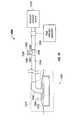
- reduced pressure treatment system 200which is a non-limiting example of reduced pressure treatment system 100 in FIG. 1 , is shown according to an illustrative embodiment.
- fluid collection apparatus 140 in FIG. 1is tube 235 fluidly connected between the dressing 215 and the reduced pressure source 210 .
- Dressing 215 and reduced pressure source 210are non-limiting examples of dressing 115 and reduced pressure source 110 in FIG. 1 , respectively.
- Tube 235includes a plurality of lumens.
- tube 235includes a delivery lumen 270 and a plurality of collection lumens 272 .
- FIG. 2shows tube 235 as having a single delivery lumen 270 and two collection lumens 272
- tube 235may have any number of delivery and collection lumens.
- multiple delivery lumens and a single collection lumenmay be included in tube 235 .
- All of the plurality of lumens in tube 235are fluidly connected to reduced pressure source 210 such that all are exposed to reduced pressure.
- reduced pressure generated by reduced pressure source 210may be transmitted through each of the plurality of lumens in tube 235 to tissue site 205 via dressing 215 .
- reduced pressure source 210applies reduced pressure to tissue site 205 through delivery lumen 270 and plurality of collection lumens 272 such that the plurality of collection lumens 272 receives a fluid 274 , such as a liquid or a liquid containing solids, from tissue site 205 .
- fluid 274is exudate from tissue site 205 .
- Plurality of collection lumens 272may store fluid 274 received from tissue site 205 .
- Reduced pressure treatment system 200may include at least one filter coupled to tube 235 .
- tube 235includes a delivery lumen filter 276 and collection lumen filter 278 .
- Delivery lumen filter 276 and collection lumen filter 278prevents fluid 274 from tissue site 205 from passing or flowing past the one or more locations at which the filters are located.
- Delivery lumen filter 276 and collection lumen filter 278may be any type of filter capable of preventing the flow of fluid 274 , such as a hydrophobic filter, a hydrophilic filter, and a mechanical valve.
- a one-way valvesuch as a duck-bill valve, may be used.
- Delivery lumen filter 276is coupled to the end of tube 235 that is adjacent to tissue site 205 and dressing 215 .
- “adjacent”means at or near another object.
- a first objectmay be adjacent to a particular object if the first object is nearer to the particular object than a second object.
- a first end of tube 235may be adjacent to tissue site 205 if the first end of the tube is nearer to tissue site 205 than a second end of the tube.
- Delivery lumen filter 276restrains or prevents fluid 274 from entering delivery lumen 270 through dressing 215 . Thus, reduced pressure may continually be applied via delivery lumen 270 unobstructed by fluid 274 , even as fluid 274 is collected into plurality of collection lumens 274 .
- FIG. 2shows delivery lumen filter 276 as preventing any fluid 274 from entering delivery lumen 270
- delivery lumen filter 276may also be placed so as to prevent fluid 274 from passing a particular point along delivery lumen 270 .
- delivery lumen filter 276may be placed inside of delivery lumen 270 at a particular distance away from an end of tube 235 such that fluid 274 is allowed to enter a portion of delivery lumen 270 unobstructed by delivery lumen filter 276 . Additional details regarding the placement and coupling of delivery lumen filter 276 is provided in FIGS. 4-6 below.
- Collection lumen filter 278is coupled to the end of tube 235 that is adjacent to reduced pressure source 210 . Collection lumen filter 278 prevents fluid 274 from entering reduced pressure source 210 or from exiting plurality of collection lumens 272 . Due to the location of collection lumen filter 278 , plurality of collection lumens 272 between the dressing 215 and collection lumen filter 278 are reservoirs capable of receiving exudate and other fluids from tissue site 205 . Since plurality of collection lumens 272 are influenced by reduced pressure source 210 , fluids are drawn from tissue site 205 through manifold 220 , which is adjacent to tissue site 205 , into plurality of collection lumens 272 .
- the volume of space available for fluiddepends upon the diameter and number of collection lumens in plurality of collection lumens 272 , as well as the length of each collection lumen between dressing 215 and collection lumen filter 278 .
- plurality of collection lumens 272may be capable holding approximately 30-60 cubic centimeters of fluid 274 .
- the aforementioned physical parameters of plurality of collection lumens 272may be adjusted based on the particular implementation such that plurality of collection lumens 272 may store any amount of fluid 274 .
- plurality of collection lumens 272continue to be capable of transmitting reduced pressure from reduced pressure source 210 .
- reduced pressuremay no longer be capable of being transmitted through plurality of collection lumens 272 .
- delivery lumen 270continues to transmit reduced pressure even after the plurality of collection lumens 272 is full.
- collection lumen filter 278is shown as being coupled to the end of tube 235 that is adjacent to reduced pressure source 210 , collection lumen filter 278 may be located anywhere along tube 235 .
- collection lumen filter 278may be located at a midpoint along the length of tube 235 .
- plurality of collection lumens 272may fill with fluid 274 until fluid 274 becomes obstructed by collection lumen filter 278 at the midpoint of tube 235 .
- collection lumen filter 278prevents fluid 274 from passing the midpoint of tube 235 along plurality of collection lumens 272 . In this example, only a portion of the space defined by plurality of collection lumens 272 may fill with fluid 274 .
- reduced pressure treatment system 200may include multiple collection lumen filters.
- each collection lumen filtermay be located at a different location along each collection lumen in plurality of collection lumens 272 .
- each collection lumen in plurality of collection lumens 272may have a different fluid capacity.
- reduced pressure treatment system 200may be used to treat low-exudating tissue sites, the smaller fluid collection volume provided by plurality of collection lumens 272 (as opposed to a dedicated canister) has little or no effect on the ability of reduced pressure treatment system 200 to provide treatment for an extended period of time.
- the compact nature of a fluid collection apparatus that is integrated into a reduced pressure delivery tubeminimizes patient discomfort and maximizes patient mobility.
- tube 235may be easily replaced with a new tube.
- plurality of collection lumens 272may be partially filled or packed with desiccants, absorptive materials, or other trapping agents.
- Tube 235may include at least one substantially transparent tube portion through which fluid 274 may be visible.
- the one or more substantially transparent tube portionsmay be a window on tube 235 made from a transparent material. Each of these windows may extend across portions of tube 235 that are adjacent to each respective collection lumen 272 .
- the material from which tube 235 is mademay be a transparent material.
- fluid 274may be visible due to the total transparency of tube 235 .
- fluid levels within plurality of collection lumens 272may be easily ascertainable by a user.
- Tube 235also includes demarcations 280 .
- Demarcations 280indicate an amount of fluid 274 in plurality of collection lumens 272 .
- demarcations 280may be included along each the windows.
- Each of demarcations 280may correspond to a specific volume or amount of fluid 274 .
- the first of demarcations 280may be labeled “5 cc” and each demarcation thereafter may be labeled in 5 cubic centimeters increments. The particular incremented used may depend on the implementation.
- FIG. 3a cross-sectional view of tube 300 is shown from the perspective of cross-sectional indicator labeled “FIG. 3 ” in FIG. 2 .
- delivery lumen 270has a larger cross-section than each of collection lumens 272 .
- the cross-section of delivery lumen 270may be the same or smaller than the cross-section of each of collection lumens 272 .
- Delivery lumen 270 and collection lumens 272also have a circular cross-section shape.
- delivery lumen 270 and collection lumens 272may have any cross-sectional shape, such as an oval, polygonal, or irregular cross-sectional shape.
- Each of collection lumens 272are shown as equidistant from delivery lumen 270 such that collection lumens 272 surrounds delivery lumen 270 in a circular pattern.
- delivery lumen 270 and collection lumens 272may have any spatial configuration relative to one another, including configurations in which each of collection lumens 272 are a different distance from delivery lumen 270 .
- tube 300may include two or more delivery lumens such as delivery lumen 270 . Any number of collection lumens 272 may also be included in tube 300 . In one example, the number of delivery lumens in tube 300 exceeds the number of collection lumens.
- Delivery lumen 270is also shown to be located along the longitudinal center of tube 300 . However, delivery lumen 270 may be located along any longitudinal axis that traverses the length of tube 300 . In one example, delivery lumen 270 and collection lumens 272 may be defined by walls that longitudinally extend through the length of tube 300 . In this example, two or more intersecting walls may define quadrants, any of which may be a delivery lumen or collection lumen.
- Tube 400includes delivery tube filter 276 , which is coupled to tube 400 at the opening of delivery lumen 270 .
- Delivery tube filter 276may have the same or slightly larger cross-section than delivery lumen 270 to ensure the delivery tube filter 276 can prevent fluid from entering delivery lumen 270 .
- Delivery lumen filter 276may be coupled to the end of tube 400 using any method. For example, delivery lumen filter 276 may be welded, screwed, glued, bolted, air-lock sealed, snapped, or pressed onto the end of tube 400 .
- FIG. 5a cross-sectional view of tube 500 is shown from the perspective of cross-sectional indicator labeled “FIG. 5 ” in FIG. 4 .
- FIG. 5shows the opening of delivery lumen 270 obstructed by delivery lumen filter 276 such that fluid from a tissue site cannot enter delivery lumen 270 .
- delivery lumen filter 270is shown to be located just outside of delivery lumen 270 such that delivery lumen filter 270 overhangs the diameter of delivery lumen 270 at overhanging portions 277 .
- Delivery lumen filter 276may have any thickness sufficient to prevent the flow of fluid into delivery lumen 270 .
- the openings of collection lumens 272are unobstructed by delivery lumen filter 276 such that fluid may be received and collected by collection lumens 272 .
- FIG. 6a cross-sectional view of tube 600 is shown in which delivery lumen filter 276 has a different size and configuration as delivery lumen filter 276 in FIG. 5 .
- delivery lumen filter 276has a diameter approximately equal to the diameter of delivery tube 270 such that delivery lumen filter 276 fits into the space defined by delivery lumen 270 .
- delivery lumen filter 276is shown to be positioned at the end of delivery lumen 270 , delivery lumen filter 276 may be located anywhere along the length of delivery lumen 270 .
- delivery lumen filter 276prevents fluid from a tissue site from passing the location at which delivery lumen filter 276 is located along delivery lumen 270 .
- Tube 700includes collection lumen filter 278 .
- Collection lumen filter 278is shown to be coupled to an end of tube 700 .
- Collection lumen filter 278is also shown as decoupled from the end of tube 700 to better show the shape of collection lumen filter.
- Collection lumen filter 278is a disk having an aperture 279 . When coupled onto the end of tube 700 , collection lumen filter 278 covers collection lumens 272 but does not cover delivery lumen 270 , as aperture 279 is located at the opening of delivery lumen 270 .
- collection lumen filter 278may prevent fluid that has been collected by collection lumen filter 278 from exiting collection lumens 272 and entering a reduced pressure source, such as reduced pressure source 210 in FIG. 2 . However, reduced pressure may still be applied through collection lumen filter 278 such that collection lumens 272 may transmit reduced pressure to a tissue site.
- collection lumen filter 278is shown to have an “O” shape, collection lumen filter 278 may have any shape capable of preventing fluid from exiting one or more of collection lumens 272 .
- Collection lumen filter 278may be coupled to the end of tube 700 using any method.
- collection lumen filter 278may be welded, screwed, glued, bolted, air-lock sealed, snapped, or pressed onto the end of tube 700 .
- FIG. 8a cross-sectional view of tube 500 is shown from the perspective of cross-sectional indicator labeled “FIG. 8 ” in FIG. 7 .
- FIG. 8shows the opening of collection lumens 272 obstructed by collection lumen filter 278 such that fluid from a tissue site cannot exit collection lumens 272 or enter a reduced pressure source.
- collection lumen filter 278is shown to be located just outside collection lumens 272 such that collection lumen filter 278 overhangs each diameter of each collection lumen 272 .
- Collection lumen filter 278may have any thickness sufficient to prevent the flow of fluid out of collection lumens 278 .
- the opening of delivery lumen 270is unobstructed by collection lumen filter 278 such that no hindrance exists between the opening of delivery lumen 270 and a reduced pressure source.
- collection lumen filter 278has a different size and configuration as collection lumen filter 278 in FIG. 8 .
- collection lumen filter 278includes multiple collection lumen filters, each of which are located inside the space defined by collection lumens 272 .
- the diameter of each collection lumen filter 278is approximately equal to the diameter of each collection lumen 272 such that collection lumen filters 278 fit into collection lumens 272 .
- each of collection lumen filtersmay be mechanical valves that prevent the flow of liquid, such as exudate, but do not prevent the flow of gas, thereby allowing the flow of reduced pressure across collection lumen filters 278 .
- collection lumen filters 278are shown to be positioned at the ends of each collection lumen 272 , collection lumen filters 278 may be located anywhere along the length of collection lumens 272 , thereby defining a fluid capacity for each collection lumen 272 . Each one of collection lumen filter 278 may also be located at different locations along each respective collection lumen 272 such that each collection lumen 272 has a different fluid capacity.
- reduced pressure treatment system 1000which is a non-limiting example of reduced pressure system 100 in FIG. 1 , is shown according to an illustrative embodiment.
- reduced pressure treatment system 1000includes a non-limiting example of reduced pressure feedback system 155 in FIG. 1 .
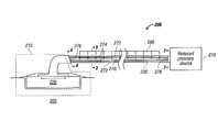
- Reduced pressure treatment system 1000includes reduced pressure source 1010 , which generates a reduced pressure that may be applied to tissue site 1005 .
- Reduced pressure treatment system 1000also includes indicator housing 1000 , which is disposed between two portions of delivery tube 1035 .
- Delivery tube 1035is a non-limiting example of delivery tube 135 in FIG. 1 .
- Indicator housing 1000includes connecting portion 1086 . Connecting portion 1086 transmits the reduced pressure from one portion of delivery tube 1035 to another portion of delivery tube 1035 . Connecting portion 1086 also contains a same or similar amount of reduced pressure as that contained by delivery tube 1035 .
- Indicator housing 1000includes indicator 1088 , which is slidably coupled to an opening along tube portion 1090 of indicator housing 1085 .
- Indicator 1088may have a cylindrical shape. Indicator 1088 may have an oval or polygonal cross-sectional shape. Indicator 1088 may also be any color, such as red, orange, or yellow.
- Indicator 1088responds to an amount of reduced pressure present in reduced pressure treatment system 1000 such that a user may determine whether a desired or therapeutic amount of reduced pressure is being applied to tissue site 1005 .
- indicator 1088is movable into a plurality of positions along axis 1092 .
- the plurality of positionsmay include a retracted position. In the retracted position, indicator 1088 may be fully or partially retracted into tube portion 1090 such that indicator 1088 is partially or fully non-visible to a user.
- the plurality of positionsmay also include an extended position. In FIG. 10 , indicator 1088 is shown in the extended position. In the extended position, indicator 1088 may be fully or partially protruding from tube portion 1090 such that indicator 1088 is visible by a user.
- the plurality of positionsmay also include any position between a fully extended and a fully retracted position.
- Reduced pressure treatment system 1000also includes a compressible member, such as a spring, that is coupled to indicator 1088 and is located in tube portion 1090 .
- the compressible memberis not shown in FIG. 10 , but will be described in greater detail in FIGS. 11 and 12 below.
- the compressible memberexerts a biasing force on indicator 1088 that biases indicator 1088 toward the extended position.
- the biasing forceis exerted in the direction indicated by arrow 1093 .
- indicator housing 1085may be located anywhere in reduced pressure treatment system 1000 at which a reduced pressure being applied to tissue site 1005 may be detected.
- indicator housing 1085along with indicator 1088 , may be located anywhere at dressing 1015 , including sealing member 1025 or connector 1045 .
- Dotted indicator 1094shows the example in which indicator housing 1085 , along with indicator 1088 , is located on sealing member 1025 .
- indicator housing 1085 , along with indicator 1088may be located on either end of a single delivery tube that couples reduced pressure source 1010 to dressing 1015 .
- indicator 1088moves into a retracted position in the presence of reduced pressure from reduced pressure source 1010 .
- indicator 1088may move into the retracted position when a reduced pressure is present in delivery tube 1035 and connecting portion 1086 .
- indicator 1088In moving into the retracted position, indicator 1088 must overcome the biasing force being exerted by the compressible member in the direction indicated by arrow 1093 .
- a sufficiently high reduced pressure in connecting portion 1086may overcome this biasing force and pull indicator 1088 into the refracted position.
- the amount of reduced pressure that is required to overcome the biasing forcemay depend on the amount of biasing force exerted by the compressible member. In the example in which the compressible member is a coiled spring, the spring constant of the coiled spring determines the amount of reduced pressure necessary to pull indicator 1088 into the retracted position.
- indicator 1088moves into the refracted position when the reduced pressure in delivery tube 1035 exceeds a first threshold reduced pressure.
- the first threshold reduced pressuremay be determined by a user and may be implemented by varying the biasing force exerted by the compressible member. For example, a user may select a compressible member with a spring constant that requires the reduced pressure in delivery tube 1035 to exceed a therapeutic reduced pressure in order for indicator 1088 to be pulled into the retracted position.
- indicator 1088moves into the retracted position when an absolute pressure generated by the reduced pressure source is equal to or less than approximately 125 millimeters of mercury.
- a user of reduced pressure treatment system 1000may be able to visually detect when a therapeutic reduced pressure is being applied to tissue site 1005 by observing that indicator 1088 does not protrude from tube portion 1090 .
- the compressible membermay bias indicator 1088 into the extended position when the reduced pressure in delivery tube 1035 is less than a second threshold reduced pressure.
- the first threshold reduced pressureis the same as the second threshold reduced pressure.
- the first threshold reduced pressureis different from the second threshold reduced pressure such that the indicator is in a fully retracted position when the reduced pressure exceeds the first reduced pressure threshold and is in a fully extended position when the reduced pressure is less than the second reduced pressure threshold.
- indicator 1088may be in an intermediate position between the fully retracted and the fully extended position when the reduced pressure is between the first and second reduced pressure thresholds.
- compressible memberbiases indicator 1088 into the extended position in an absence of reduced pressure in delivery tube 1035 .
- the absence of reduced pressureis due to reduced pressure source 1010 being turned off. Because the compressible member in tube portion 1090 biases indicator 1088 to protrude from tube portion 1090 when the reduced pressure is absent or below a threshold amount, a user may visually detect when a therapeutic pressure is not being applied to tissue site 1005 by observing that indicator 1088 protrudes from tube portion 1090 . The user may then take the necessary action to apply a therapeutic pressure to tissue site 1005 . On reason why the reduced pressure in delivery tube 1035 may be absent or below a threshold amount is because of a leak in delivery tube 1035 or elsewhere in reduced pressure treatment system 1000 . In this circumstance, a user is alerted to a possible leakage when indicator 1088 is in the extended position.
- FIG. 11a reduced pressure feedback system 1100 , such as that shown in FIG. 10 , is shown in accordance with an illustrative embodiment.
- indicator 1088is in an extended position in reduced pressure feedback system 1100 .
- Connecting portion 1086is slidingly engaged with the two portions of delivery tube 1035 to form a sealed fit.
- Connecting portion 1086 of indicator housing 1085may also be sealingly engaged with the two portions of delivery tube 1035 in a variety of ways.
- connecting portion 1086may be welded, screwed, glued, bolted, air-lock sealed, or snapped to the two portions of delivery tube 1035 .
- the compressible memberis a coiled spring.
- Tube portion 1090 of indicator housing 1085includes base 1096 , to which an end of coiled spring 1095 is coupled. However, the end of coiled spring 1095 that is not attached to indicator 1088 may be attached to any other component of indicator housing with which a coiled spring maybe used to exert a biasing force on indicator 1088 .
- the inner surface of tube portion 1090is a tubular opening along which indicator 1088 may slide into refracted and extended positions.
- Coiled spring 1095is contained by a plurality of corrugations 1097 that form part of a tubular wall. Corrugations 1097 allow the tubular wall to be compressed and expanded without causing lateral stress to the inner wall of tubular portion 1090 .
- Reduced pressure feedback system 1100also includes cap 1098 .
- Cap 1098may be composed of a transparent material that allows a user to view indicator 1088 when indicator 1088 is in the extended position.
- cap 1098is also sealingly engaged with the remainder of indicator housing 1085 so that reduced pressure does not escape through the tubular opening in indicator housing 1085 .
- coiled spring 1095may have any spring constant.
- the spring constant of coiled spring 1095determines the biasing force that is exerted upon indicator 1088 toward the extended position.
- coiled spring 1095has a spring constant such that coiled spring 1095 biases indicator 1088 into the extended position when an absolute pressure in delivery tube 1035 exceeds approximately 125 millimeters of mercury.
- Other coiled springs having other spring constantsmay also be used to bias indicator 1088 into the extended position when the absolute pressure in delivery tube 1035 exceeds other absolute pressure thresholds, such as desired therapeutic pressure thresholds.
- reduced pressure feedback system 1200which is a non-limiting example of reduced pressure feedback system 1100 , is shown in accordance with an illustrative embodiment.
- reduced pressure feedback system 1200shows indicator 1088 in a retracted position.
- indicator 1088When indicator 1088 is in a retracted position, reduced pressure from delivery tube 1035 is transferred to indicator 1088 through the tubular wall formed from corrugations 1097 .
- This reduced pressureexerts a pulling force upon indicator 1088 that is sufficient to overcome the biasing force exerted by coiled spring 1095 in the opposite direction.
- Indicator 1088is thus pulled out of transparent cap 1098 and out of the view of a user of the reduced pressure treatment system.
- cap 1098may be coupled to indicator 1088 such that cap 1098 is also retracted into tube portion 1090 when indicator 1088 is in the retracted position.
- reduced pressure feedback system 1300which is a non-limiting example of the reduced pressure feedback system shown in FIG. 10 , is shown in an illustrative embodiment.
- the perspective view of FIG. 13shows the circular cross-section of indicator 1088 , cap 1098 , tube portion 1090 , as well as opening 1099 through which indicator 1088 protrudes.
- These componentsmay have any cross-sectional shape, such as an oval or polygon.
- FIG. 14a graph showing the relation between the reduced pressure in delivery tube 1035 and the position of indicator 1088 is shown in accordance with an illustrative embodiment.
- indicator 1088moves toward the fully retracted position.
- indicator 1088moves toward the full retracted position in a linear fashion as indicated by graph line 1410 .
- the relation between the reduced pressure and the position of indicator 1088may also follow other patterns, as indicated by graph lines 1415 and 1420 . Other patterns, such as a stair-step pattern, may also characterize the relation between the reduced pressure and the position of indicator 1088 .
- indicator 1088is in the fully retracted position when the reduced pressure corresponds to an absolute pressure of 125 millimeters of mercury.
- FIG. 15a process that may be implemented by a reduced pressure treatment system such as reduced pressure treatment system 200 in FIG. 2 is shown in accordance with an illustrative embodiment.
- the processapplies reduced pressure to a tissue site via a plurality of lumens in a delivery tube (step 1505 ).
- the processstores fluid from the tissue site in at least one collection lumen in the plurality of lumens (step 1510 ).
- the processdetermines a fluid level of the fluid in the at least one collection lumen based on a plurality of demarcations on the delivery tube (step 1515 ).
- FIG. 16a process that may be implemented by a reduced pressure treatment system such as reduced pressure treatment system 1000 in FIG. 10 is shown in accordance with an illustrative embodiment.
- the processapplies a reduced pressure to the tissue site using a reduced pressure source (step 1605 ).
- the processdetermines whether there is a presence of a threshold amount of reduced pressure in a delivery tube or other component of a reduced pressure treatment system (step 1610 ). If the process determines that there is not a presence of a threshold amount of reduced pressure, the process moves an indicator into an extended position using a compressible member. The process then returns to step 1605 . Returning to step 1610 , if the process determines that there is a presence of a threshold amount of reduced pressure, the process moves the indicator into the retracted position (step 1620 ).
Landscapes
- Health & Medical Sciences (AREA)
- Heart & Thoracic Surgery (AREA)
- Engineering & Computer Science (AREA)
- Animal Behavior & Ethology (AREA)
- Public Health (AREA)
- Biomedical Technology (AREA)
- Hematology (AREA)
- Life Sciences & Earth Sciences (AREA)
- Veterinary Medicine (AREA)
- General Health & Medical Sciences (AREA)
- Anesthesiology (AREA)
- Vascular Medicine (AREA)
- Otolaryngology (AREA)
- Dermatology (AREA)
- Medical Informatics (AREA)
- Media Introduction/Drainage Providing Device (AREA)
- Surgical Instruments (AREA)
- External Artificial Organs (AREA)
- Materials For Medical Uses (AREA)
Abstract
Description
Claims (13)
Priority Applications (3)
| Application Number | Priority Date | Filing Date | Title |
|---|---|---|---|
| US13/290,889US8915896B2 (en) | 2007-02-09 | 2011-11-07 | Apparatus and method for administering reduced pressure treatment to a tissue site |
| US14/551,746US9925316B2 (en) | 2007-02-09 | 2014-11-24 | Apparatus and method for administering reduced pressure treatment to a tissue site |
| US15/894,681US20180221549A1 (en) | 2007-02-09 | 2018-02-12 | Apparatus and method for administering reduced pressure treatment to a tissue site |
Applications Claiming Priority (3)
| Application Number | Priority Date | Filing Date | Title |
|---|---|---|---|
| US90041507P | 2007-02-09 | 2007-02-09 | |
| US12/069,363US8057449B2 (en) | 2007-02-09 | 2008-02-08 | Apparatus and method for administering reduced pressure treatment to a tissue site |
| US13/290,889US8915896B2 (en) | 2007-02-09 | 2011-11-07 | Apparatus and method for administering reduced pressure treatment to a tissue site |
Related Parent Applications (1)
| Application Number | Title | Priority Date | Filing Date |
|---|---|---|---|
| US12/069,363ContinuationUS8057449B2 (en) | 2007-02-09 | 2008-02-08 | Apparatus and method for administering reduced pressure treatment to a tissue site |
Related Child Applications (1)
| Application Number | Title | Priority Date | Filing Date |
|---|---|---|---|
| US14/551,746ContinuationUS9925316B2 (en) | 2007-02-09 | 2014-11-24 | Apparatus and method for administering reduced pressure treatment to a tissue site |
Publications (2)
| Publication Number | Publication Date |
|---|---|
| US20120046626A1 US20120046626A1 (en) | 2012-02-23 |
| US8915896B2true US8915896B2 (en) | 2014-12-23 |
Family
ID=39690676
Family Applications (4)
| Application Number | Title | Priority Date | Filing Date |
|---|---|---|---|
| US12/069,363Active2029-08-14US8057449B2 (en) | 2007-02-09 | 2008-02-08 | Apparatus and method for administering reduced pressure treatment to a tissue site |
| US13/290,889Active2029-07-21US8915896B2 (en) | 2007-02-09 | 2011-11-07 | Apparatus and method for administering reduced pressure treatment to a tissue site |
| US14/551,746Active2029-10-17US9925316B2 (en) | 2007-02-09 | 2014-11-24 | Apparatus and method for administering reduced pressure treatment to a tissue site |
| US15/894,681AbandonedUS20180221549A1 (en) | 2007-02-09 | 2018-02-12 | Apparatus and method for administering reduced pressure treatment to a tissue site |
Family Applications Before (1)
| Application Number | Title | Priority Date | Filing Date |
|---|---|---|---|
| US12/069,363Active2029-08-14US8057449B2 (en) | 2007-02-09 | 2008-02-08 | Apparatus and method for administering reduced pressure treatment to a tissue site |
Family Applications After (2)
| Application Number | Title | Priority Date | Filing Date |
|---|---|---|---|
| US14/551,746Active2029-10-17US9925316B2 (en) | 2007-02-09 | 2014-11-24 | Apparatus and method for administering reduced pressure treatment to a tissue site |
| US15/894,681AbandonedUS20180221549A1 (en) | 2007-02-09 | 2018-02-12 | Apparatus and method for administering reduced pressure treatment to a tissue site |
Country Status (14)
| Country | Link |
|---|---|
| US (4) | US8057449B2 (en) |
| EP (2) | EP2859903B1 (en) |
| JP (3) | JP5038439B2 (en) |
| KR (1) | KR101174963B1 (en) |
| CN (1) | CN101600465B (en) |
| AU (1) | AU2008216787B2 (en) |
| BR (1) | BRPI0806210A2 (en) |
| CA (2) | CA2674025C (en) |
| IL (1) | IL199732A0 (en) |
| MX (1) | MX2009008399A (en) |
| RU (1) | RU2459636C2 (en) |
| TW (1) | TWI359035B (en) |
| WO (1) | WO2008100446A2 (en) |
| ZA (1) | ZA200904345B (en) |
Cited By (14)
| Publication number | Priority date | Publication date | Assignee | Title |
|---|---|---|---|---|
| US20140330225A1 (en)* | 2007-12-06 | 2014-11-06 | Smith & Nephew Plc | Apparatus for topical negative pressure therapy |
| US9289542B2 (en) | 2003-10-28 | 2016-03-22 | Smith & Nephew Plc | Wound cleansing apparatus |
| US9452248B2 (en) | 2003-10-28 | 2016-09-27 | Smith & Nephew Plc | Wound cleansing apparatus in-situ |
| US9545463B2 (en) | 2004-04-28 | 2017-01-17 | Smith & Nephew Plc | Wound treatment apparatus and method |
| US9844473B2 (en) | 2002-10-28 | 2017-12-19 | Smith & Nephew Plc | Apparatus for aspirating, irrigating and cleansing wounds |
| US10010658B2 (en) | 2013-05-10 | 2018-07-03 | Smith & Nephew Plc | Fluidic connector for irrigation and aspiration of wounds |
| US10413644B2 (en) | 2004-04-27 | 2019-09-17 | Smith & Nephew Plc | Wound treatment apparatus and method |
| US11298453B2 (en) | 2003-10-28 | 2022-04-12 | Smith & Nephew Plc | Apparatus and method for wound cleansing with actives |
| US20240082477A1 (en)* | 2011-06-24 | 2024-03-14 | 3M Innovative Properties Company | Reduced-pressure dressings employing tissue-fixation elements |
| US12035968B2 (en) | 2014-05-18 | 2024-07-16 | Eximo Medical Ltd. | System for tissue ablation using pulsed laser |
| US12038322B2 (en) | 2022-06-21 | 2024-07-16 | Eximo Medical Ltd. | Devices and methods for testing ablation systems |
| US12042223B2 (en) | 2011-02-24 | 2024-07-23 | Eximo Medical Ltd. | Hybrid catheter for vascular intervention |
| US12193736B2 (en) | 2016-05-05 | 2025-01-14 | Eximo Medical Ltd. | Apparatus and methods for resecting and/or ablating an undesired tissue |
| US12376904B1 (en) | 2020-09-08 | 2025-08-05 | Angiodynamics, Inc. | Dynamic laser stabilization and calibration system |
Families Citing this family (109)
| Publication number | Priority date | Publication date | Assignee | Title |
|---|---|---|---|---|
| CN1822874B (en) | 2003-07-22 | 2010-10-13 | 凯希特许有限公司 | Negative pressure wound treatment dressing |
| GB0508531D0 (en) | 2005-04-27 | 2005-06-01 | Smith & Nephew | Sai with ultrasound |
| CA2949821C (en) | 2005-09-06 | 2021-05-18 | Smith & Nephew, Inc. | Self contained wound dressing with micropump |
| US8235939B2 (en) | 2006-02-06 | 2012-08-07 | Kci Licensing, Inc. | System and method for purging a reduced pressure apparatus during the administration of reduced pressure treatment |
| US8366690B2 (en) | 2006-09-19 | 2013-02-05 | Kci Licensing, Inc. | System and method for determining a fill status of a canister of fluid in a reduced pressure treatment system |
| US7876546B2 (en)* | 2006-09-19 | 2011-01-25 | Kci Licensing Inc. | Component module for a reduced pressure treatment system |
| US8061360B2 (en) | 2006-09-19 | 2011-11-22 | Kci Licensing, Inc. | System and method for locating fluid leaks at a drape of a reduced pressure delivery system |
| WO2008036361A2 (en) | 2006-09-19 | 2008-03-27 | Kci Licensing Inc. | Reduced pressure treatment system having blockage clearing and dual-zone pressure protection capabilities |
| EP1905465B2 (en) | 2006-09-28 | 2013-11-27 | Smith & Nephew, Inc. | Portable wound therapy system |
| ES2564519T3 (en) | 2006-10-13 | 2016-03-23 | Bluesky Medical Group Inc. | Pressure control of a medical vacuum pump |
| AU2007311028B2 (en)* | 2006-10-17 | 2013-06-27 | Smith & Nephew Plc | Auxiliary powered negative pressure wound therapy apparatuses and methods |
| CA2674997C (en) | 2007-02-09 | 2012-08-14 | Kci Licensing, Inc. | A breathable interface system for topical reduced pressure |
| WO2008100446A2 (en) | 2007-02-09 | 2008-08-21 | Kci Licensing Inc. | Apparatus and method for administering reduced pressure treatment to a tissue site |
| US8267908B2 (en)* | 2007-02-09 | 2012-09-18 | Kci Licensing, Inc. | Delivery tube, system, and method for storing liquid from a tissue site |
| EP2129409B2 (en) | 2007-03-14 | 2021-11-24 | The Board of Trustees of the Leland Stanford Junior University | Devices for application of reduced pressure therapy |
| EP2152333B1 (en)* | 2007-05-07 | 2012-10-17 | Carmeli Adahan | Suction system |
| SE531259C2 (en)* | 2007-06-27 | 2009-02-03 | Moelnlycke Health Care Ab | Device for treating reduced pressure ulcers |
| GB0712763D0 (en) | 2007-07-02 | 2007-08-08 | Smith & Nephew | Apparatus |
| GB0712764D0 (en) | 2007-07-02 | 2007-08-08 | Smith & Nephew | Carrying Bag |
| US9408954B2 (en) | 2007-07-02 | 2016-08-09 | Smith & Nephew Plc | Systems and methods for controlling operation of negative pressure wound therapy apparatus |
| GB0715259D0 (en) | 2007-08-06 | 2007-09-12 | Smith & Nephew | Canister status determination |
| GB0712736D0 (en)* | 2007-07-02 | 2007-08-08 | Smith & Nephew | Apparatus |
| GB0712739D0 (en) | 2007-07-02 | 2007-08-08 | Smith & Nephew | Apparatus |
| US12121648B2 (en) | 2007-08-06 | 2024-10-22 | Smith & Nephew Plc | Canister status determination |
| EP2203137B1 (en)* | 2007-10-11 | 2016-02-24 | Spiracur, Inc. | Closed incision negative pressure wound therapy device |
| US20130096518A1 (en) | 2007-12-06 | 2013-04-18 | Smith & Nephew Plc | Wound filling apparatuses and methods |
| GB0723874D0 (en)* | 2007-12-06 | 2008-01-16 | Smith & Nephew | Dressing |
| US11253399B2 (en) | 2007-12-06 | 2022-02-22 | Smith & Nephew Plc | Wound filling apparatuses and methods |
| US8377017B2 (en) | 2008-01-03 | 2013-02-19 | Kci Licensing, Inc. | Low-profile reduced pressure treatment system |
| WO2009086580A1 (en)* | 2008-01-07 | 2009-07-16 | Cerulean Medical Pty Ltd | Negative pressure treatment device |
| US8366692B2 (en) | 2008-01-08 | 2013-02-05 | Richard Scott Weston | Sustained variable negative pressure wound treatment and method of controlling same |
| AU2009214439B2 (en) | 2008-02-14 | 2014-09-25 | Solventum Intellectual Properties Company | Devices and methods for treatment of damaged tissue |
| GB0803564D0 (en)* | 2008-02-27 | 2008-04-02 | Smith & Nephew | Fluid collection |
| US9033942B2 (en) | 2008-03-07 | 2015-05-19 | Smith & Nephew, Inc. | Wound dressing port and associated wound dressing |
| US8021347B2 (en) | 2008-07-21 | 2011-09-20 | Tyco Healthcare Group Lp | Thin film wound dressing |
| US8298200B2 (en) | 2009-06-01 | 2012-10-30 | Tyco Healthcare Group Lp | System for providing continual drainage in negative pressure wound therapy |
| AU2009223037A1 (en) | 2008-03-12 | 2009-09-17 | Smith & Nephew Plc | Negative pressure dressing and method of using same |
| EP2977067B1 (en) | 2008-03-13 | 2020-12-09 | 3M Innovative Properties Company | Apparatus for applying reduced pressure to a tissue site on a foot |
| US8152785B2 (en) | 2008-03-13 | 2012-04-10 | Tyco Healthcare Group Lp | Vacuum port for vacuum wound therapy |
| CA2729201C (en)* | 2008-06-27 | 2016-06-21 | Davol, Inc. | Endoscopic vacuum controller |
| US8257326B2 (en) | 2008-06-30 | 2012-09-04 | Tyco Healthcare Group Lp | Apparatus for enhancing wound healing |
| WO2010005709A1 (en) | 2008-07-08 | 2010-01-14 | Tyco Healthcare Group Lp | Portable negative pressure wound therapy device |
| ES2658263T3 (en) | 2008-08-08 | 2018-03-09 | Smith & Nephew, Inc. | Continuous fiber wound dressing |
| US8251979B2 (en) | 2009-05-11 | 2012-08-28 | Tyco Healthcare Group Lp | Orientation independent canister for a negative pressure wound therapy device |
| US8827983B2 (en) | 2008-08-21 | 2014-09-09 | Smith & Nephew, Inc. | Sensor with electrical contact protection for use in fluid collection canister and negative pressure wound therapy systems including same |
| US8216198B2 (en) | 2009-01-09 | 2012-07-10 | Tyco Healthcare Group Lp | Canister for receiving wound exudate in a negative pressure therapy system |
| US9414968B2 (en) | 2008-09-05 | 2016-08-16 | Smith & Nephew, Inc. | Three-dimensional porous film contact layer with improved wound healing |
| US8158844B2 (en) | 2008-10-08 | 2012-04-17 | Kci Licensing, Inc. | Limited-access, reduced-pressure systems and methods |
| MX2011005192A (en) | 2008-11-19 | 2011-06-01 | Kci Licensing Inc | Dynamic, reduced-pressure treatment systems and methods. |
| CA2744548C (en)* | 2008-11-25 | 2017-06-13 | Spiracur Inc. | Device for delivery of reduced pressure to body surfaces |
| WO2010078353A2 (en)* | 2008-12-31 | 2010-07-08 | Kci Licensing, Inc. | Systems for providing fluid flow to tissues |
| CA2745462C (en) | 2008-12-31 | 2014-07-15 | Kci Licensing, Inc. | Tissue roll scaffolds |
| CA2746525C (en) | 2008-12-31 | 2017-12-12 | Kci Licensing, Inc. | Manifolds, systems, and methods for administering reduced pressure to a subcutaneous tissue site |
| US8361043B2 (en)* | 2009-01-07 | 2013-01-29 | Spiracur Inc. | Reduced pressure therapy of the sacral region |
| US8162907B2 (en) | 2009-01-20 | 2012-04-24 | Tyco Healthcare Group Lp | Method and apparatus for bridging from a dressing in negative pressure wound therapy |
| US8728045B2 (en)* | 2009-03-04 | 2014-05-20 | Spiracur Inc. | Devices and methods to apply alternating level of reduced pressure to tissue |
| JP5650199B2 (en) | 2009-04-10 | 2015-01-07 | スピレイカー・インコーポレイテッドSpiracur, Inc. | Method and apparatus for attaching a negative pressure closure therapy system for a closed incision |
| US8444614B2 (en) | 2009-04-10 | 2013-05-21 | Spiracur, Inc. | Methods and devices for applying closed incision negative pressure wound therapy |
| US20100305523A1 (en)* | 2009-05-27 | 2010-12-02 | Tyco Healthcare Group Lp | Active Exudate Control System |
| US20110196321A1 (en) | 2009-06-10 | 2011-08-11 | Tyco Healthcare Group Lp | Fluid Collection Canister Including Canister Top with Filter Membrane and Negative Pressure Wound Therapy Systems Including Same |
| US20100324516A1 (en) | 2009-06-18 | 2010-12-23 | Tyco Healthcare Group Lp | Apparatus for Vacuum Bridging and/or Exudate Collection |
| US8529526B2 (en)* | 2009-10-20 | 2013-09-10 | Kci Licensing, Inc. | Dressing reduced-pressure indicators, systems, and methods |
| AU2010341491B2 (en) | 2009-12-22 | 2015-05-14 | Smith & Nephew, Inc. | Apparatuses and methods for negative pressure wound therapy |
| US8377018B2 (en)* | 2009-12-23 | 2013-02-19 | Kci Licensing, Inc. | Reduced-pressure, multi-orientation, liquid-collection canister |
| USRE48117E1 (en) | 2010-05-07 | 2020-07-28 | Smith & Nephew, Inc. | Apparatuses and methods for negative pressure wound therapy |
| US8403902B2 (en)* | 2010-05-18 | 2013-03-26 | Kci Licensing, Inc. | Reduced-pressure medical systems and methods employing a moisture processing device |
| US8795246B2 (en) | 2010-08-10 | 2014-08-05 | Spiracur Inc. | Alarm system |
| US8753322B2 (en) | 2010-08-10 | 2014-06-17 | Spiracur Inc. | Controlled negative pressure apparatus and alarm mechanism |
| CN101947348B (en)* | 2010-09-03 | 2012-03-07 | 惠州市华阳医疗电子有限公司 | Negative pressure wound therapy system capable of detecting colors of exudates |
| CN101940804B (en)* | 2010-09-03 | 2012-08-29 | 惠州市华阳医疗电子有限公司 | Negative pressure wound therapeutic system capable of detecting and displaying transudate volume |
| CN101947349B (en)* | 2010-09-03 | 2013-03-06 | 惠州市华阳医疗电子有限公司 | Negative pressure wound treatment system based on wound exudate management |
| CN101966364A (en)* | 2010-09-03 | 2011-02-09 | 惠州市华阳多媒体电子有限公司 | Negative pressure wound treatment system capable of detecting air leakage rate |
| US9526920B2 (en) | 2010-10-12 | 2016-12-27 | Smith & Nephew, Inc. | Medical device |
| WO2012065309A1 (en)* | 2010-11-19 | 2012-05-24 | 惠州市华阳多媒体电子有限公司 | Negative-pressure wound treating system capable of displaying relationship chart between exudate volume and viscosity |
| CN201969175U (en)* | 2010-12-20 | 2011-09-14 | 惠州市华阳多媒体电子有限公司 | Negative-pressure wound therapy system capable of detecting smell of wound exudate |
| RU2016111981A (en) | 2010-12-22 | 2018-11-27 | Смит Энд Нефью, Инк. | DEVICE AND METHOD FOR TREATING RAS WITH NEGATIVE PRESSURE |
| USD714433S1 (en) | 2010-12-22 | 2014-09-30 | Smith & Nephew, Inc. | Suction adapter |
| US9302034B2 (en) | 2011-04-04 | 2016-04-05 | Smith & Nephew, Inc. | Negative pressure wound therapy dressing |
| CN106730060B (en) | 2011-05-27 | 2020-12-04 | 凯希特许有限公司 | Systems and methods for delivering fluid to a wound therapy dressing |
| RU2611760C2 (en) | 2011-06-07 | 2017-02-28 | Смит Энд Нефью Плс | Wound contacting elements and methods of their use |
| CN103764186B (en)* | 2011-07-26 | 2016-05-04 | 凯希特许有限公司 | Systems and methods for treating a tissue site with reduced pressure, involving a reduced-pressure interface having a multi-lumen catheter for contacting a manifold |
| CN202236824U (en)* | 2011-08-29 | 2012-05-30 | 惠州市华阳医疗电子有限公司 | Negative pressure wound therapy system with exudate flow rate alarm function |
| EP2776084B1 (en)* | 2011-11-11 | 2015-10-28 | KCI Licensing, Inc. | Reduced-pressure, tunnel-wound dressings, systems, and methods |
| JP6202686B2 (en)* | 2011-11-18 | 2017-09-27 | ケーシーアイ ライセンシング インコーポレイテッド | Tissue treatment system and method having a porous substrate having a contraction region and an expansion region |
| JP6250571B2 (en)* | 2012-03-12 | 2017-12-20 | スミス アンド ネフュー ピーエルシーSmith & Nephew Public Limited Company | Pressure reducing apparatus and method |
| JP6400570B2 (en) | 2012-05-23 | 2018-10-10 | スミス アンド ネフュー ピーエルシーSmith & Nephew Public Limited Company | Apparatus and method for local negative pressure closure therapy |
| WO2014020440A1 (en) | 2012-08-01 | 2014-02-06 | Smith & Nephew Plc | Wound dressing |
| CN108186200B (en) | 2012-08-01 | 2021-08-10 | 史密夫及内修公开有限公司 | Wound dressing |
| GB201216928D0 (en)* | 2012-09-21 | 2012-11-07 | I2R Medical Ltd | Portable medical device system |
| ES2817834T3 (en) | 2013-03-12 | 2021-04-08 | 3M Innovative Properties Co | System that uses vacuum to promote the healing of sprains |
| US9737649B2 (en) | 2013-03-14 | 2017-08-22 | Smith & Nephew, Inc. | Systems and methods for applying reduced pressure therapy |
| JP2016517318A (en) | 2013-03-14 | 2016-06-16 | スミス アンド ネフュー インコーポレーテッド | System and method for administering decompression therapy |
| WO2015023515A1 (en) | 2013-08-13 | 2015-02-19 | Smith & Nephew, Inc. | Systems and methods for applying reduced pressure therapy |
| BR112016007156B1 (en)* | 2013-10-02 | 2022-12-13 | 3M Innovative Properties Company | REDUCED PRESSURE SYSTEM |
| US11026847B2 (en) | 2014-06-02 | 2021-06-08 | Zdzislaw Harry Piotrowski | Systems and methods for wound healing |
| US10022274B1 (en)* | 2014-06-02 | 2018-07-17 | Zdzislaw Harry Piotrowski | Systems and methods for wound healing |
| CA3179001A1 (en) | 2014-07-31 | 2016-02-04 | Smith & Nephew, Inc. | Systems and methods for applying reduced pressure therapy |
| US12133789B2 (en) | 2014-07-31 | 2024-11-05 | Smith & Nephew, Inc. | Reduced pressure therapy apparatus construction and control |
| DE102014013419A1 (en)* | 2014-09-10 | 2016-03-10 | Fresenius Medical Care Deutschland Gmbh | Device comprising a multi-lumen tube |
| WO2016069890A1 (en)* | 2014-10-29 | 2016-05-06 | Shakam LLC | Negative pressure wound therapy dressing and drainage apparatus and system |
| US10076594B2 (en) | 2015-05-18 | 2018-09-18 | Smith & Nephew Plc | Fluidic connector for negative pressure wound therapy |
| CN109069713A (en) | 2016-05-13 | 2018-12-21 | 史密夫和内修有限公司 | Automatic wound in negative pressure wound treating system couples detection |
| JP7349364B2 (en)* | 2016-11-28 | 2023-09-22 | アイノバ メディカル ピーティーワイ リミテッド | percutaneous drainage device |
| US10624794B2 (en) | 2018-02-12 | 2020-04-21 | Healyx Labs, Inc. | Negative pressure wound therapy systems, devices, and methods |
| EP3773782A4 (en) | 2018-05-16 | 2022-03-02 | Midwest Training and Development Services, LLC | Negative pressure wound apposition dressing system |
| GB201811449D0 (en) | 2018-07-12 | 2018-08-29 | Smith & Nephew | Apparatuses and methods for negative pressure wound therapy |
| GB202000574D0 (en) | 2020-01-15 | 2020-02-26 | Smith & Nephew | Fluidic connectors for negative pressure wound therapy |
| US20230256156A1 (en)* | 2020-08-14 | 2023-08-17 | Kci Manufacturing Unlimited Company | Decompression wrap |
| US20240197981A1 (en)* | 2021-04-23 | 2024-06-20 | 3M Innovative Properties Company | Wound Therapy System |
Citations (241)
| Publication number | Priority date | Publication date | Assignee | Title |
|---|---|---|---|---|
| US1355846A (en) | 1920-02-06 | 1920-10-19 | David A Rannells | Medical appliance |
| US2547758A (en) | 1949-01-05 | 1951-04-03 | Wilmer B Keeling | Instrument for treating the male urethra |
| US2632443A (en) | 1949-04-18 | 1953-03-24 | Eleanor P Lesher | Surgical dressing |
| GB692578A (en) | 1949-09-13 | 1953-06-10 | Minnesota Mining & Mfg | Improvements in or relating to drape sheets for surgical use |
| US2682873A (en) | 1952-07-30 | 1954-07-06 | Johnson & Johnson | General purpose protective dressing |
| US2910763A (en) | 1955-08-17 | 1959-11-03 | Du Pont | Felt-like products |
| US2969057A (en) | 1957-11-04 | 1961-01-24 | Brady Co W H | Nematodic swab |
| US3066672A (en) | 1960-09-27 | 1962-12-04 | Jr William H Crosby | Method and apparatus for serial sampling of intestinal juice |
| US3367332A (en) | 1965-08-27 | 1968-02-06 | Gen Electric | Product and process for establishing a sterile area of skin |
| US3376868A (en) | 1964-06-04 | 1968-04-09 | Howe Sound Co | Surgical evacuator device |
| US3382867A (en) | 1965-03-22 | 1968-05-14 | Ruby L. Reaves | Body portion developing device with combined vacuum and vibrating means |
| US3520300A (en) | 1967-03-15 | 1970-07-14 | Amp Inc | Surgical sponge and suction device |
| US3568675A (en) | 1968-08-30 | 1971-03-09 | Clyde B Harvey | Fistula and penetrating wound dressing |
| US3589356A (en) | 1969-09-04 | 1971-06-29 | Daniel Silverman | Method for everting and extraverting flexible tubing into a body cavity |
| US3595241A (en)* | 1969-02-19 | 1971-07-27 | David S Sheridan | Insured internal flow medicosurgical tubes |
| US3648692A (en) | 1970-12-07 | 1972-03-14 | Parke Davis & Co | Medical-surgical dressing for burns and the like |
| US3682180A (en) | 1970-06-08 | 1972-08-08 | Coilform Co Inc | Drain clip for surgical drain |
| US3742952A (en) | 1971-04-28 | 1973-07-03 | Alpha Ind Inc | Surgical suction pump assembly |
| US3774611A (en) | 1972-06-08 | 1973-11-27 | J Tussey | Stabilized contamination free surgical evacuator |
| US3779243A (en) | 1971-10-15 | 1973-12-18 | J Tussey | Contamination free surgical evacuator |
| US3823716A (en) | 1972-08-14 | 1974-07-16 | Simpla Plastics | Urinary drainage devices |
| US3826254A (en) | 1973-02-26 | 1974-07-30 | Verco Ind | Needle or catheter retaining appliance |
| US3875941A (en) | 1974-04-03 | 1975-04-08 | Medical Dynamics Inc | System for evacuating fluids from the body |
| US3957054A (en) | 1973-09-26 | 1976-05-18 | Mcfarlane Richard H | Surgical drainage tube |
| DE2640413A1 (en) | 1976-09-08 | 1978-03-09 | Wolf Gmbh Richard | CATHETER MONITORING DEVICE |
| US4080970A (en) | 1976-11-17 | 1978-03-28 | Miller Thomas J | Post-operative combination dressing and internal drain tube with external shield and tube connector |
| US4096853A (en) | 1975-06-21 | 1978-06-27 | Hoechst Aktiengesellschaft | Device for the introduction of contrast medium into an anus praeter |
| US4139004A (en) | 1977-02-17 | 1979-02-13 | Gonzalez Jr Harry | Bandage apparatus for treating burns |
| US4141361A (en) | 1970-02-09 | 1979-02-27 | Snyder Manufacturing Co., Incorporated | Evacuator |
| US4165748A (en) | 1977-11-07 | 1979-08-28 | Johnson Melissa C | Catheter tube holder |
| US4184510A (en) | 1977-03-15 | 1980-01-22 | Fibra-Sonics, Inc. | Valued device for controlling vacuum in surgery |
| WO1980002182A1 (en) | 1979-04-06 | 1980-10-16 | J Moss | Portable suction device for collecting fluids from a closed wound |
| US4233969A (en) | 1976-11-11 | 1980-11-18 | Lock Peter M | Wound dressing materials |
| US4245630A (en) | 1976-10-08 | 1981-01-20 | T. J. Smith & Nephew, Ltd. | Tearable composite strip of materials |
| US4250882A (en) | 1979-01-26 | 1981-02-17 | Medical Dynamics, Inc. | Wound drainage device |
| US4256109A (en) | 1978-07-10 | 1981-03-17 | Nichols Robert L | Shut off valve for medical suction apparatus |
| US4261363A (en) | 1979-11-09 | 1981-04-14 | C. R. Bard, Inc. | Retention clips for body fluid drains |
| US4275721A (en) | 1978-11-28 | 1981-06-30 | Landstingens Inkopscentral Lic, Ekonomisk Forening | Vein catheter bandage |
| US4284079A (en) | 1979-06-28 | 1981-08-18 | Adair Edwin Lloyd | Method for applying a male incontinence device |
| US4297995A (en) | 1980-06-03 | 1981-11-03 | Key Pharmaceuticals, Inc. | Bandage containing attachment post |
| US4329743A (en) | 1979-04-27 | 1982-05-18 | College Of Medicine And Dentistry Of New Jersey | Bio-absorbable composite tissue scaffold |
| US4333468A (en) | 1980-08-18 | 1982-06-08 | Geist Robert W | Mesentery tube holder apparatus |
| US4373519A (en) | 1981-06-26 | 1983-02-15 | Minnesota Mining And Manufacturing Company | Composite wound dressing |
| US4382441A (en) | 1978-12-06 | 1983-05-10 | Svedman Paul | Device for treating tissues, for example skin |
| JPS5895841U (en) | 1981-12-21 | 1983-06-29 | 住友ベークライト株式会社 | Medical body fluid drain tube |
| US4392853A (en) | 1981-03-16 | 1983-07-12 | Rudolph Muto | Sterile assembly for protecting and fastening an indwelling device |
| US4392858A (en) | 1981-07-16 | 1983-07-12 | Sherwood Medical Company | Wound drainage device |
| US4419097A (en) | 1981-07-31 | 1983-12-06 | Rexar Industries, Inc. | Attachment for catheter tube |
| EP0100148A1 (en) | 1982-07-06 | 1984-02-08 | Dow Corning Limited | Medical-surgical dressing and a process for the production thereof |
| US4433973A (en) | 1982-01-12 | 1984-02-28 | Bioresearch Inc. | Reusable tube connector assembly |
| US4465485A (en) | 1981-03-06 | 1984-08-14 | Becton, Dickinson And Company | Suction canister with unitary shut-off valve and filter features |
| EP0117632A2 (en) | 1983-01-27 | 1984-09-05 | Johnson & Johnson Products Inc. | Adhesive film dressing |
| US4475909A (en) | 1982-05-06 | 1984-10-09 | Eisenberg Melvin I | Male urinary device and method for applying the device |
| US4480638A (en) | 1980-03-11 | 1984-11-06 | Eduard Schmid | Cushion for holding an element of grafted skin |
| US4523920A (en) | 1983-12-05 | 1985-06-18 | Sil-Fab Corporation | Surgical suction drain |
| US4525374A (en) | 1984-02-27 | 1985-06-25 | Manresa, Inc. | Treating hydrophobic filters to render them hydrophilic |
| US4525166A (en) | 1981-11-21 | 1985-06-25 | Intermedicat Gmbh | Rolled flexible medical suction drainage device |
| US4529402A (en) | 1980-07-08 | 1985-07-16 | Snyder Laboratories, Inc. | Closed wound suction evacuator with rotary valve |
| US4540412A (en) | 1983-07-14 | 1985-09-10 | The Kendall Company | Device for moist heat therapy |
| US4543100A (en) | 1983-11-01 | 1985-09-24 | Brodsky Stuart A | Catheter and drain tube retainer |
| US4548202A (en) | 1983-06-20 | 1985-10-22 | Ethicon, Inc. | Mesh tissue fasteners |
| US4551139A (en) | 1982-02-08 | 1985-11-05 | Marion Laboratories, Inc. | Method and apparatus for burn wound treatment |
| EP0161865A2 (en) | 1984-05-03 | 1985-11-21 | Smith and Nephew Associated Companies p.l.c. | Adhesive wound dressing |
| US4569348A (en) | 1980-02-22 | 1986-02-11 | Velcro Usa Inc. | Catheter tube holder strap |
| US4573965A (en) | 1984-02-13 | 1986-03-04 | Superior Plastic Products Corp. | Device for draining wounds |
| US4579555A (en) | 1983-12-05 | 1986-04-01 | Sil-Fab Corporation | Surgical gravity drain having aligned longitudinally extending capillary drainage channels |
| US4605399A (en) | 1984-12-04 | 1986-08-12 | Complex, Inc. | Transdermal infusion device |
| US4608041A (en) | 1981-10-14 | 1986-08-26 | Frese Nielsen | Device for treatment of wounds in body tissue of patients by exposure to jets of gas |
| US4640688A (en) | 1985-08-23 | 1987-02-03 | Mentor Corporation | Urine collection catheter |
| US4642093A (en) | 1984-02-08 | 1987-02-10 | Haerle Anton | Aspirator for withdrawal of secretions from wounds |
| US4643719A (en) | 1984-07-19 | 1987-02-17 | Garth Geoffrey C | Manually operable aspirator |
| US4655754A (en) | 1984-11-09 | 1987-04-07 | Stryker Corporation | Vacuum wound drainage system and lipids baffle therefor |
| US4664662A (en) | 1984-08-02 | 1987-05-12 | Smith And Nephew Associated Companies Plc | Wound dressing |
| US4664652A (en) | 1985-02-07 | 1987-05-12 | Snyder Laboratories, Inc. | Wound evacuator |
| US4681570A (en) | 1985-12-26 | 1987-07-21 | Dalton Michael J | Peritoneal catheter |
| WO1987004626A1 (en) | 1986-01-31 | 1987-08-13 | Osmond, Roger, L., W. | Suction system for wound and gastro-intestinal drainage |
| US4710165A (en) | 1985-09-16 | 1987-12-01 | Mcneil Charles B | Wearable, variable rate suction/collection device |
| US4733659A (en) | 1986-01-17 | 1988-03-29 | Seton Company | Foam bandage |
| GB2195255A (en) | 1986-09-30 | 1988-04-07 | Vacutec Uk Limited | Method and apparatus for vacuum treatment of an epidermal surface |
| US4743232A (en) | 1986-10-06 | 1988-05-10 | The Clinipad Corporation | Package assembly for plastic film bandage |
| GB2197789A (en) | 1986-11-28 | 1988-06-02 | Smiths Industries Plc | Anti-foaming disinfectants used in surgical suction apparatus |
| US4758220A (en) | 1985-09-26 | 1988-07-19 | Alcon Laboratories, Inc. | Surgical cassette proximity sensing and latching apparatus |
| US4787888A (en) | 1987-06-01 | 1988-11-29 | University Of Connecticut | Disposable piezoelectric polymer bandage for percutaneous delivery of drugs and method for such percutaneous delivery (a) |
| US4826494A (en) | 1984-11-09 | 1989-05-02 | Stryker Corporation | Vacuum wound drainage system |
| US4838883A (en) | 1986-03-07 | 1989-06-13 | Nissho Corporation | Urine-collecting device |
| US4840187A (en) | 1986-09-11 | 1989-06-20 | Bard Limited | Sheath applicator |
| US4863449A (en) | 1987-07-06 | 1989-09-05 | Hollister Incorporated | Adhesive-lined elastic condom cathether |
| US4872450A (en) | 1984-08-17 | 1989-10-10 | Austad Eric D | Wound dressing and method of forming same |
| US4878901A (en) | 1986-10-10 | 1989-11-07 | Sachse Hans Ernst | Condom catheter, a urethral catheter for the prevention of ascending infections |
| GB2220357A (en) | 1988-05-28 | 1990-01-10 | Smiths Industries Plc | Medico-surgical containers |
| US4897081A (en) | 1984-05-25 | 1990-01-30 | Thermedics Inc. | Percutaneous access device |
| US4906233A (en) | 1986-05-29 | 1990-03-06 | Terumo Kabushiki Kaisha | Method of securing a catheter body to a human skin surface |
| US4906240A (en) | 1988-02-01 | 1990-03-06 | Matrix Medica, Inc. | Adhesive-faced porous absorbent sheet and method of making same |
| US4919654A (en) | 1988-08-03 | 1990-04-24 | Kalt Medical Corporation | IV clamp with membrane |
| CA2005436A1 (en) | 1988-12-13 | 1990-06-13 | Glenda G. Kalt | Transparent tracheostomy tube dressing |
| US4941882A (en) | 1987-03-14 | 1990-07-17 | Smith And Nephew Associated Companies, P.L.C. | Adhesive dressing for retaining a cannula on the skin |
| US4953565A (en) | 1986-11-26 | 1990-09-04 | Shunro Tachibana | Endermic application kits for external medicines |
| WO1990010424A1 (en) | 1989-03-16 | 1990-09-20 | Smith & Nephew Plc | Absorbent devices and precursors therefor |
| US4969880A (en) | 1989-04-03 | 1990-11-13 | Zamierowski David S | Wound dressing and treatment method |
| US4981474A (en) | 1988-02-16 | 1991-01-01 | Baxter Travenol Laboratories, Inc. | Body fluid drainage device |
| US4985019A (en) | 1988-03-11 | 1991-01-15 | Michelson Gary K | X-ray marker |
| GB2235877A (en) | 1989-09-18 | 1991-03-20 | Antonio Talluri | Closed wound suction apparatus |
| US5013300A (en) | 1989-03-09 | 1991-05-07 | Williams James D | Apparatus for suction lipectomy surgery |
| US5019059A (en) | 1986-12-15 | 1991-05-28 | Uresil Corporation | Apparatus and method for collecting body fluids |
| US5034006A (en) | 1987-06-22 | 1991-07-23 | Takeda Chemical Industries, Ltd. | Suction equipment for medical operation |
| US5037397A (en) | 1985-05-03 | 1991-08-06 | Medical Distributors, Inc. | Universal clamp |
| US5086170A (en) | 1989-01-16 | 1992-02-04 | Roussel Uclaf | Process for the preparation of azabicyclo compounds |
| US5092858A (en) | 1990-03-20 | 1992-03-03 | Becton, Dickinson And Company | Liquid gelling agent distributor device |
| US5100396A (en) | 1989-04-03 | 1992-03-31 | Zamierowski David S | Fluidic connection system and method |
| US5100395A (en) | 1989-10-06 | 1992-03-31 | Lior Rosenberg | Fluid drain for wounds |
| US5102404A (en) | 1986-12-15 | 1992-04-07 | Uresil Corporation | Apparatus and method for collecting body fluids |
| US5108364A (en) | 1989-02-16 | 1992-04-28 | Sumitomo Bakelte Company Limited | Monitoring catheter for medical use |
| US5112323A (en) | 1990-02-08 | 1992-05-12 | Snyder Laboratories, Inc. | Wound evacuator |
| US5116310A (en) | 1990-07-30 | 1992-05-26 | Helix Medical, Inc. | Multiple lumen wound drain with bypass openings |
| US5134994A (en) | 1990-02-12 | 1992-08-04 | Say Sam L | Field aspirator in a soft pack with externally mounted container |
| US5149331A (en) | 1991-05-03 | 1992-09-22 | Ariel Ferdman | Method and device for wound closure |
| US5167613A (en) | 1992-03-23 | 1992-12-01 | The Kendall Company | Composite vented wound dressing |
| US5176663A (en) | 1987-12-02 | 1993-01-05 | Pal Svedman | Dressing having pad with compressibility limiting elements |
| WO1993009727A1 (en) | 1991-11-14 | 1993-05-27 | Wake Forest University | Method and apparatus for treating tissue damage |
| US5215522A (en) | 1984-07-23 | 1993-06-01 | Ballard Medical Products | Single use medical aspirating device and method |
| US5232453A (en) | 1989-07-14 | 1993-08-03 | E. R. Squibb & Sons, Inc. | Catheter holder |
| US5242428A (en) | 1991-10-04 | 1993-09-07 | Aubrey Palestrant | Apparatus for wetting hydrophilic-coated guide wires and catheters |
| US5259399A (en) | 1992-03-02 | 1993-11-09 | Alan Brown | Device and method of causing weight loss using removable variable volume intragastric bladder |
| US5261893A (en) | 1989-04-03 | 1993-11-16 | Zamierowski David S | Fastening system and method |
| US5266071A (en) | 1986-03-28 | 1993-11-30 | Nancy W. Elftman | Method for using percutaneous accessport |
| US5278100A (en) | 1991-11-08 | 1994-01-11 | Micron Technology, Inc. | Chemical vapor deposition technique for depositing titanium silicide on semiconductor wafers |
| US5279550A (en) | 1991-12-19 | 1994-01-18 | Gish Biomedical, Inc. | Orthopedic autotransfusion system |
| US5298015A (en) | 1989-07-11 | 1994-03-29 | Nippon Zeon Co., Ltd. | Wound dressing having a porous structure |
| US5324306A (en) | 1991-10-30 | 1994-06-28 | Howmedica, Inc. | Hemostatic implant introducer |
| US5342376A (en) | 1993-05-03 | 1994-08-30 | Dermagraphics, Inc. | Inserting device for a barbed tissue connector |
| US5342329A (en) | 1991-10-11 | 1994-08-30 | Inmed Ltda. | Portable disposable device for post-surgical suction |
| US5344415A (en) | 1993-06-15 | 1994-09-06 | Deroyal Industries, Inc. | Sterile system for dressing vascular access site |
| DE4306478A1 (en) | 1993-03-02 | 1994-09-08 | Wolfgang Dr Wagner | Drainage device, in particular pleural drainage device, and drainage method |
| WO1994020041A1 (en) | 1993-03-09 | 1994-09-15 | Wake Forest University | Wound treatment employing reduced pressure |
| JPH0670746U (en) | 1993-03-25 | 1994-10-04 | 住友ベークライト株式会社 | Medical drain tube |
| JPH06285155A (en) | 1993-03-30 | 1994-10-11 | Kaoru Sakatani | Suction tool for surgical operation |
| US5358494A (en) | 1989-07-11 | 1994-10-25 | Svedman Paul | Irrigation dressing |
| US5358492A (en) | 1991-05-02 | 1994-10-25 | Feibus Miriam H | Woven surgical drain and method of making |
| US5405322A (en) | 1993-08-12 | 1995-04-11 | Boston Scientific Corporation | Method for treating aneurysms with a thermal source |
| US5437651A (en) | 1993-09-01 | 1995-08-01 | Research Medical, Inc. | Medical suction apparatus |
| US5437622A (en) | 1992-04-29 | 1995-08-01 | Laboratoire Hydrex (Sa) | Transparent adhesive dressing with reinforced starter cuts |
| DE29504378U1 (en) | 1995-03-15 | 1995-09-14 | MTG Medizinisch, technische Gerätebau GmbH, 66299 Friedrichsthal | Electronically controlled low-vacuum pump for chest and wound drainage |
| US5470316A (en) | 1993-09-07 | 1995-11-28 | United States Surgical Corporation | Body tissue penetrating device having a vacuum indicator |
| WO1996005873A1 (en) | 1994-08-22 | 1996-02-29 | Kinetic Concepts Inc. | Wound drainage equipment |
| US5527293A (en) | 1989-04-03 | 1996-06-18 | Kinetic Concepts, Inc. | Fastening system and method |
| US5549584A (en) | 1994-02-14 | 1996-08-27 | The Kendall Company | Apparatus for removing fluid from a wound |
| US5549579A (en) | 1992-11-20 | 1996-08-27 | Specialty Silicone Fabricators | Unitary drain and method for making |
| US5556375A (en) | 1994-06-16 | 1996-09-17 | Hercules Incorporated | Wound dressing having a fenestrated base layer |
| US5569184A (en) | 1992-04-29 | 1996-10-29 | Cardiovascular Dynamics, Inc. | Delivery and balloon dilatation catheter and method of using |
| US5607388A (en) | 1994-06-16 | 1997-03-04 | Hercules Incorporated | Multi-purpose wound dressing |
| WO1997018007A1 (en) | 1995-11-14 | 1997-05-22 | Kci Medical Limited | Portable wound treatment apparatus |
| US5643589A (en) | 1992-12-04 | 1997-07-01 | Chalmers; Susanna Elizabeth | Desiccant formulated for treating wounds or lesions |
| US5676634A (en) | 1994-03-30 | 1997-10-14 | Khouri Biomedical Research, Inc. | Method and apparatus for soft tissue enlargement with balanced force appliance |
| US5713874A (en) | 1995-08-01 | 1998-02-03 | Kind-R-Ject Company, Llc | Camouflaged injection needle |
| US5735833A (en) | 1996-12-11 | 1998-04-07 | Bristol-Myers Squibb Co. | Lavage tip |
| US5762640A (en) | 1995-05-31 | 1998-06-09 | Nec Corporation | Effusion fluid sucking device |
| US5820581A (en) | 1994-08-19 | 1998-10-13 | Lifenet Research Foundation | Process for cleaning large bone grafts and bone grafts produced thereby |
| JPH11501837A (en) | 1995-03-16 | 1999-02-16 | オリジン・メドシステムズ・インク | Inflation device to separate tissue layers |
| WO1999013793A1 (en) | 1997-09-12 | 1999-03-25 | Kci Medical Limited | Surgical drape and suction head for wound treatment |
| US5914264A (en) | 1994-12-30 | 1999-06-22 | Reconstructive Technologies | Apparatus for growing vertebrate skin in vitro |
| US5941859A (en) | 1997-03-17 | 1999-08-24 | Lerman; Benjamin S. | Wound irrigation shield with fluid scavenging |
| US5980503A (en) | 1996-04-08 | 1999-11-09 | Guidant Corporation | Endoscopic cardioplegia infusion cannula and method of use |
| US5984942A (en) | 1997-04-02 | 1999-11-16 | Femrx, Inc. | Methods and systems for reducing tissue adhesion |
| US6042537A (en) | 1997-08-13 | 2000-03-28 | Kaiser; Daniel | Method and apparatus for tissue enlargement |
| US6071267A (en) | 1998-02-06 | 2000-06-06 | Kinetic Concepts, Inc. | Medical patient fluid management interface system and method |
| US6080243A (en) | 1998-06-18 | 2000-06-27 | 3M Innovative Properties Company | Fluid guide device having an open structure surface for attachement to a fluid transport source |
| US6135116A (en) | 1997-07-28 | 2000-10-24 | Kci Licensing, Inc. | Therapeutic method for treating ulcers |
| US6174306B1 (en) | 1995-05-13 | 2001-01-16 | Wim Fleischmann | Device for vacuum-sealing an injury |
| WO2001034223A1 (en) | 1999-11-09 | 2001-05-17 | Kci Medical Limited | Wound suction device with multi-lumen connector |
| WO2001036021A1 (en) | 1999-11-15 | 2001-05-25 | Allegiance Corporation | Wound drain with portals to enable uniform suction |
| US6241747B1 (en) | 1993-05-03 | 2001-06-05 | Quill Medical, Inc. | Barbed Bodily tissue connector |
| US6287316B1 (en) | 1999-03-26 | 2001-09-11 | Ethicon, Inc. | Knitted surgical mesh |
| JP2001252349A (en) | 2000-03-09 | 2001-09-18 | Sachiko Yanagida | Tube for drainage |
| US6394948B1 (en) | 1995-09-20 | 2002-05-28 | Medtronic, Inc. | Method and apparatus for temporarily immobilizing a local area of tissue |
| US20020065494A1 (en) | 2000-11-29 | 2002-05-30 | Lockwood Jeffrey S. | Vacuum therapy and cleansing dressing for wounds |
| US6398767B1 (en) | 1997-05-27 | 2002-06-04 | Wilhelm Fleischmann | Process and device for application of active substances to a wound surface area |
| US20020077661A1 (en) | 2000-12-20 | 2002-06-20 | Vahid Saadat | Multi-barbed device for retaining tissue in apposition and methods of use |
| US20020099343A1 (en) | 2001-01-23 | 2002-07-25 | Teddy Garcia | Suction device for removing material from skin pores |
| US20020115951A1 (en) | 2001-02-22 | 2002-08-22 | Core Products International, Inc. | Ankle brace providing upper and lower ankle adjustment |
| US20020120185A1 (en) | 2000-05-26 | 2002-08-29 | Kci Licensing, Inc. | System for combined transcutaneous blood gas monitoring and vacuum assisted wound closure |
| US6458109B1 (en) | 1998-08-07 | 2002-10-01 | Hill-Rom Services, Inc. | Wound treatment apparatus |
| US20020143286A1 (en) | 2001-03-05 | 2002-10-03 | Kci Licensing, Inc. | Vacuum assisted wound treatment apparatus and infection identification system and method |
| US20020161346A1 (en) | 2000-11-29 | 2002-10-31 | Lockwood Jeffrey S. | Vacuum therapy and cleansing dressing for wounds |
| US6488643B1 (en) | 1998-10-08 | 2002-12-03 | Kci Licensing, Inc. | Wound healing foot wrap |
| US6493568B1 (en) | 1994-07-19 | 2002-12-10 | Kci Licensing, Inc. | Patient interface system |
| AU755496B2 (en) | 1997-09-12 | 2002-12-12 | Kci Licensing, Inc. | Surgical drape and suction head for wound treatment |
| US20020198504A1 (en) | 2000-11-29 | 2002-12-26 | Risk James R. | Wound treatment apparatus |
| US20020198503A1 (en) | 2000-11-29 | 2002-12-26 | Risk James R. | Wound treatment apparatus |
| US6500112B1 (en) | 1994-03-30 | 2002-12-31 | Brava, Llc | Vacuum dome with supporting rim and rim cushion |
| US20030014022A1 (en) | 2001-07-12 | 2003-01-16 | Lockwood Jeffrey S. | Control of vacuum level rate of change |
| US20030040687A1 (en) | 2001-08-24 | 2003-02-27 | Kci Licensing, Inc | Vacuum assisted tissue treatment system |
| US20030057070A1 (en) | 2001-09-07 | 2003-03-27 | Shih-Chieh Wang | Power switch apparatus |
| US6551280B1 (en) | 2000-06-30 | 2003-04-22 | Embro Corporation | Therapeutic device and system |
| US20030088209A1 (en) | 2000-02-16 | 2003-05-08 | Jessica Chiu | Multi-lumen extrusion tubing |
| US6572594B2 (en) | 1999-08-18 | 2003-06-03 | R.S. Medical Equipment Llc | Skin treatment using neuromuscular stimulation and a treatment gas containing medicine |
| WO2003057070A2 (en) | 2001-12-26 | 2003-07-17 | Hill-Rom Services Inc. | Vented vacuum bandage and method |
| US6626891B2 (en) | 1997-07-03 | 2003-09-30 | Polymedics N.V. | Drainage system to be used with an open wound, an element which is used thereby for placing a drainage tube or hose, and a method of using said drainage system |
| US20030187367A1 (en) | 2002-03-22 | 2003-10-02 | Odland Rick Mathew | System for treating tissue swelling |
| TW558444B (en) | 2001-10-11 | 2003-10-21 | Hill Rom Services Inc | Waste container for negative pressure therapy |
| US6641575B1 (en) | 1999-01-26 | 2003-11-04 | Neal M. Lonky | Surgical vacuum instrument for retracting, extracting, and manipulating tissue |
| US6641553B1 (en) | 1999-06-02 | 2003-11-04 | Boston Scientific Corporation | Devices and methods for delivering a drug |
| US6648862B2 (en) | 2001-11-20 | 2003-11-18 | Spheric Products, Ltd. | Personally portable vacuum desiccator |
| US20030216672A1 (en) | 2002-05-15 | 2003-11-20 | The Research Foundation Of State University Of New York | System and method for healing skin injuries |
| US6656149B2 (en) | 2000-04-13 | 2003-12-02 | Leland L. Ladd | Expansible medical suction canister |
| US20030225441A1 (en) | 2000-06-08 | 2003-12-04 | Kci Licensing, Inc. | Localized liquid therapy and thermotherapy device |
| US6660484B2 (en) | 1992-11-13 | 2003-12-09 | Regents Of The University Of California | Colorimetric glycopolythiophene biosensors |
| US20040006319A1 (en) | 1999-04-09 | 2004-01-08 | Lina Cesar Z. | Wound therapy device |
| US6682506B1 (en) | 1998-12-22 | 2004-01-27 | Francis Navarro | Device for maintaining at least a tube |
| US20040039406A1 (en) | 1998-06-01 | 2004-02-26 | Jessen Jonh W. | Method and apparatus for placing and maintaining a percutaneous tube into a body cavity |
| US20040064132A1 (en) | 2002-09-16 | 2004-04-01 | Boehringer John R. | Device for treating a wound |
| US20040093026A1 (en) | 2002-11-07 | 2004-05-13 | Rolf Weidenhagen | Endoscopic wound care treatment system and method |
| US6755807B2 (en) | 1999-11-29 | 2004-06-29 | Hill-Rom Services, Inc. | Wound treatment apparatus |
| US6755796B2 (en) | 1999-02-07 | 2004-06-29 | Medispec Ltd. | Pressure-pulse therapy apparatus |
| US6758836B2 (en) | 2002-02-07 | 2004-07-06 | C. R. Bard, Inc. | Split tip dialysis catheter |
| WO2004101052A2 (en) | 2003-05-12 | 2004-11-25 | I-Flow Corporation | Catheter for uniform delivery of medication |
| US6840960B2 (en) | 2002-09-27 | 2005-01-11 | Stephen K. Bubb | Porous implant system and treatment method |
| US20050065484A1 (en) | 2003-09-10 | 2005-03-24 | Watson Richard L. | Wound healing apparatus with bioabsorbable material and suction tubes |
| US20050070858A1 (en) | 2002-04-10 | 2005-03-31 | Lockwood Jeffrey S | Access openings in vacuum bandage |
| US20050137539A1 (en) | 2002-09-13 | 2005-06-23 | Biggie John J. | Closed wound drainage system |
| US20050148913A1 (en) | 2004-01-02 | 2005-07-07 | Weston Richard S. | Reduced pressure wound treatment appliance |
| US20050171467A1 (en) | 2004-01-30 | 2005-08-04 | Jaime Landman | Multiple function surgical device |
| US20050203483A1 (en) | 1999-07-02 | 2005-09-15 | Pulmonx | Methods, systems, and kits for lung volume reduction |
| JP2005528167A (en) | 2002-06-03 | 2005-09-22 | ウェイク フォーレスト ユニバーシティ ヘルス サイエンシーズ | Directed tissue growth using reduced pressure |
| US20050245906A1 (en) | 2004-04-21 | 2005-11-03 | Exploramed Nc1, Inc. | Implantable device and methods for delivering drugs and other substances to treat sinusitis and other disorders |
| WO2005105180A1 (en) | 2004-04-28 | 2005-11-10 | Smith & Nephew, Plc | Apparatus for aspirating, irrigating and/or cleansing of wounds |
| US20050261642A1 (en) | 2004-05-21 | 2005-11-24 | Weston Richard S | Flexible reduced pressure treatment appliance |
| US20050261643A1 (en) | 2002-09-13 | 2005-11-24 | Farhad Bybordi | Closed wound drainage system |
| US7070584B2 (en) | 2001-02-20 | 2006-07-04 | Kci Licensing, Inc. | Biocompatible wound dressing |
| US20060271019A1 (en) | 2004-10-15 | 2006-11-30 | The Regents Of The University Of California | Drainage system |
| US20070021698A1 (en) | 1997-05-27 | 2007-01-25 | Kci Licensing, Inc. | Process and device for application of active substances to a wound surface |
| US20070118096A1 (en) | 2005-11-21 | 2007-05-24 | Smith Joshua D | Wound care system |
| WO2007133618A2 (en) | 2006-05-11 | 2007-11-22 | Iasis Medical, Llc | Device and method for wound therapy |
| US7344512B2 (en) | 2002-03-15 | 2008-03-18 | Sun Medical Technology Research Corporation | Protector and blood pump system |
| US7396339B2 (en) | 2004-04-30 | 2008-07-08 | The First Years Inc. | Pumping breast milk |
| JP4129536B2 (en) | 2000-02-24 | 2008-08-06 | ヴェネテック インターナショナル,インコーポレイテッド | Highly compatible catheter anchoring system |
| WO2008100446A2 (en) | 2007-02-09 | 2008-08-21 | Kci Licensing Inc. | Apparatus and method for administering reduced pressure treatment to a tissue site |
| US20080275409A1 (en) | 2007-05-01 | 2008-11-06 | The Brigham And Women's Hospital, Inc. | Wound healing device |
| US7699823B2 (en) | 2005-09-07 | 2010-04-20 | Tyco Healthcare Group Lp | Wound dressing with vacuum reservoir |
| US7824384B2 (en) | 2004-08-10 | 2010-11-02 | Kci Licensing, Inc. | Chest tube drainage system |
| US7976533B2 (en) | 2003-12-22 | 2011-07-12 | Medela Holding Ag | Drainage apparatus and method |
| US20110172617A1 (en) | 2004-11-24 | 2011-07-14 | Birgit Riesinger | Drainage device for treating wounds using a reduced pressure |
Family Cites Families (24)
| Publication number | Priority date | Publication date | Assignee | Title |
|---|---|---|---|---|
| DE3011163C2 (en)† | 1980-03-22 | 1982-07-15 | Sterimed Gesellschaft für medizinischen Bedarf mbH, 6600 Saarbrücken | Suction bottle for aspirating secretions from wound cavities |
| AU550575B2 (en) | 1981-08-07 | 1986-03-27 | Richard Christian Wright | Wound drainage device |
| EP0175830A1 (en)* | 1984-09-26 | 1986-04-02 | Bay, Otto, Dipl.-Ing. | Aspirator bottle for use in the draining of wounds |
| DE3441891A1 (en)* | 1984-11-16 | 1986-05-28 | Walter Beck | METHOD AND DEVICE FOR SUCTIONING SECRETARY LIQUID FROM A Wound |
| US4795448A (en)† | 1986-08-08 | 1989-01-03 | Haemonetics Corporation | Suction collection system |
| US5002529A (en)† | 1987-07-10 | 1991-03-26 | Solco Basle, Inc. | Postoperative wound drainage |
| DE8908336U1 (en)* | 1989-07-08 | 1989-08-31 | Medinorm AG Medizintechnische Produkte, 6607 Quierschied | Hose clamp |
| RU2026085C1 (en)* | 1991-11-11 | 1995-01-09 | Институт травматологии и ортопедии Восточно-Сибирского филиала СО АМН РФ | Device for curing post-operational and purulent cavities |
| SE500395C2 (en)† | 1992-10-16 | 1994-06-20 | Humanteknik Ab | Moisture absorbing device |
| US6417605B1 (en)* | 1994-09-16 | 2002-07-09 | Micron Technology, Inc. | Method of preventing junction leakage in field emission devices |
| US5876384A (en)† | 1995-10-05 | 1999-03-02 | Dragan; William B. | Micro aspirator |
| US5992239A (en)* | 1998-09-10 | 1999-11-30 | Boehringer Laboratories, Inc. | Gauge |
| SE517247C2 (en)† | 2000-09-13 | 2002-05-14 | Dan Lundgren | Strainer for suction tubes for surgical or dental use |
| US20030021667A1 (en)* | 2001-07-27 | 2003-01-30 | Harrell Olen Spincer | Forklift attchment for carrying a barrel and dumping the contents thereof |
| US6695853B2 (en)* | 2001-11-21 | 2004-02-24 | Emed, Inc. | Microdermabrasion system and method of use |
| GB0508529D0 (en)* | 2005-04-27 | 2005-06-01 | Smith & Nephew | Sai with microstress |
| US7608066B2 (en) | 2005-08-08 | 2009-10-27 | Innovative Therapies, Inc. | Wound irrigation device pressure monitoring and control system |
| CA2949821C (en) | 2005-09-06 | 2021-05-18 | Smith & Nephew, Inc. | Self contained wound dressing with micropump |
| US20070137484A1 (en)* | 2005-12-21 | 2007-06-21 | Porous Media | Operating room body gas evacuation system |
| EP1905462A1 (en)† | 2006-09-29 | 2008-04-02 | Johnson & Johnson Regenerative Therapeutics, LLC | Hollow tissue growth devices made by lyophilization |
| US20090007969A1 (en)* | 2007-07-05 | 2009-01-08 | 3M Innovative Properties Company | Microfluidic actuation structures |
| EP3415171B1 (en) | 2008-02-27 | 2022-12-14 | 3M Innovative Properties Company | System and method for healing a wound at a tissue site |
| AU2009221772B2 (en) | 2008-03-05 | 2015-01-22 | Solventum Intellectual Properties Company | Dressing and method for applying reduced pressure to and collecting and storing fluid from a tissue site |
| SE533167C2 (en) | 2008-04-09 | 2010-07-13 | Moelnlycke Health Care Ab | Device for treating wounds and means for making wound pads |
- 2008
- 2008-02-08WOPCT/US2008/001741patent/WO2008100446A2/enactiveApplication Filing
- 2008-02-08CACA2674025Apatent/CA2674025C/enactiveActive
- 2008-02-08CNCN2008800036951Apatent/CN101600465B/enactiveActive
- 2008-02-08CACA2925998Apatent/CA2925998C/enactiveActive
- 2008-02-08RURU2009123208/14Apatent/RU2459636C2/ennot_activeIP Right Cessation
- 2008-02-08USUS12/069,363patent/US8057449B2/enactiveActive
- 2008-02-08EPEP14194747.3Apatent/EP2859903B1/enactiveActive
- 2008-02-08KRKR1020097018800Apatent/KR101174963B1/ennot_activeExpired - Fee Related
- 2008-02-08JPJP2009549125Apatent/JP5038439B2/enactiveActive
- 2008-02-08EPEP08725382.9Apatent/EP2109473B2/enactiveActive
- 2008-02-08MXMX2009008399Apatent/MX2009008399A/enactiveIP Right Grant
- 2008-02-08AUAU2008216787Apatent/AU2008216787B2/enactiveActive
- 2008-02-08BRBRPI0806210-2Apatent/BRPI0806210A2/ennot_activeIP Right Cessation
- 2008-02-12TWTW097104984Apatent/TWI359035B/ennot_activeIP Right Cessation
- 2009
- 2009-06-22ZAZA200904345Apatent/ZA200904345B/enunknown
- 2009-07-07ILIL199732Apatent/IL199732A0/enunknown
- 2011
- 2011-11-07USUS13/290,889patent/US8915896B2/enactiveActive
- 2012
- 2012-03-19JPJP2012061577Apatent/JP5600132B2/enactiveActive
- 2014
- 2014-08-14JPJP2014165058Apatent/JP6026470B2/enactiveActive
- 2014-11-24USUS14/551,746patent/US9925316B2/enactiveActive
- 2018
- 2018-02-12USUS15/894,681patent/US20180221549A1/ennot_activeAbandoned
Patent Citations (273)
| Publication number | Priority date | Publication date | Assignee | Title |
|---|---|---|---|---|
| US1355846A (en) | 1920-02-06 | 1920-10-19 | David A Rannells | Medical appliance |
| US2547758A (en) | 1949-01-05 | 1951-04-03 | Wilmer B Keeling | Instrument for treating the male urethra |
| US2632443A (en) | 1949-04-18 | 1953-03-24 | Eleanor P Lesher | Surgical dressing |
| GB692578A (en) | 1949-09-13 | 1953-06-10 | Minnesota Mining & Mfg | Improvements in or relating to drape sheets for surgical use |
| US2682873A (en) | 1952-07-30 | 1954-07-06 | Johnson & Johnson | General purpose protective dressing |
| US2910763A (en) | 1955-08-17 | 1959-11-03 | Du Pont | Felt-like products |
| US2969057A (en) | 1957-11-04 | 1961-01-24 | Brady Co W H | Nematodic swab |
| US3066672A (en) | 1960-09-27 | 1962-12-04 | Jr William H Crosby | Method and apparatus for serial sampling of intestinal juice |
| US3376868A (en) | 1964-06-04 | 1968-04-09 | Howe Sound Co | Surgical evacuator device |
| US3382867A (en) | 1965-03-22 | 1968-05-14 | Ruby L. Reaves | Body portion developing device with combined vacuum and vibrating means |
| US3367332A (en) | 1965-08-27 | 1968-02-06 | Gen Electric | Product and process for establishing a sterile area of skin |
| US3520300A (en) | 1967-03-15 | 1970-07-14 | Amp Inc | Surgical sponge and suction device |
| US3568675A (en) | 1968-08-30 | 1971-03-09 | Clyde B Harvey | Fistula and penetrating wound dressing |
| US3595241A (en)* | 1969-02-19 | 1971-07-27 | David S Sheridan | Insured internal flow medicosurgical tubes |
| US3589356A (en) | 1969-09-04 | 1971-06-29 | Daniel Silverman | Method for everting and extraverting flexible tubing into a body cavity |
| US4141361A (en) | 1970-02-09 | 1979-02-27 | Snyder Manufacturing Co., Incorporated | Evacuator |
| US3682180A (en) | 1970-06-08 | 1972-08-08 | Coilform Co Inc | Drain clip for surgical drain |
| US3648692A (en) | 1970-12-07 | 1972-03-14 | Parke Davis & Co | Medical-surgical dressing for burns and the like |
| US3742952A (en) | 1971-04-28 | 1973-07-03 | Alpha Ind Inc | Surgical suction pump assembly |
| US3779243A (en) | 1971-10-15 | 1973-12-18 | J Tussey | Contamination free surgical evacuator |
| US3774611A (en) | 1972-06-08 | 1973-11-27 | J Tussey | Stabilized contamination free surgical evacuator |
| US3823716A (en) | 1972-08-14 | 1974-07-16 | Simpla Plastics | Urinary drainage devices |
| US3826254A (en) | 1973-02-26 | 1974-07-30 | Verco Ind | Needle or catheter retaining appliance |
| US3957054A (en) | 1973-09-26 | 1976-05-18 | Mcfarlane Richard H | Surgical drainage tube |
| US3875941A (en) | 1974-04-03 | 1975-04-08 | Medical Dynamics Inc | System for evacuating fluids from the body |
| US4096853A (en) | 1975-06-21 | 1978-06-27 | Hoechst Aktiengesellschaft | Device for the introduction of contrast medium into an anus praeter |
| DE2640413A1 (en) | 1976-09-08 | 1978-03-09 | Wolf Gmbh Richard | CATHETER MONITORING DEVICE |
| US4245630A (en) | 1976-10-08 | 1981-01-20 | T. J. Smith & Nephew, Ltd. | Tearable composite strip of materials |
| US4233969A (en) | 1976-11-11 | 1980-11-18 | Lock Peter M | Wound dressing materials |
| US4080970A (en) | 1976-11-17 | 1978-03-28 | Miller Thomas J | Post-operative combination dressing and internal drain tube with external shield and tube connector |
| US4139004A (en) | 1977-02-17 | 1979-02-13 | Gonzalez Jr Harry | Bandage apparatus for treating burns |
| US4184510A (en) | 1977-03-15 | 1980-01-22 | Fibra-Sonics, Inc. | Valued device for controlling vacuum in surgery |
| US4165748A (en) | 1977-11-07 | 1979-08-28 | Johnson Melissa C | Catheter tube holder |
| US4256109A (en) | 1978-07-10 | 1981-03-17 | Nichols Robert L | Shut off valve for medical suction apparatus |
| US4275721A (en) | 1978-11-28 | 1981-06-30 | Landstingens Inkopscentral Lic, Ekonomisk Forening | Vein catheter bandage |
| US4382441A (en) | 1978-12-06 | 1983-05-10 | Svedman Paul | Device for treating tissues, for example skin |
| US4250882A (en) | 1979-01-26 | 1981-02-17 | Medical Dynamics, Inc. | Wound drainage device |
| WO1980002182A1 (en) | 1979-04-06 | 1980-10-16 | J Moss | Portable suction device for collecting fluids from a closed wound |
| US4329743A (en) | 1979-04-27 | 1982-05-18 | College Of Medicine And Dentistry Of New Jersey | Bio-absorbable composite tissue scaffold |
| US4284079A (en) | 1979-06-28 | 1981-08-18 | Adair Edwin Lloyd | Method for applying a male incontinence device |
| US4261363A (en) | 1979-11-09 | 1981-04-14 | C. R. Bard, Inc. | Retention clips for body fluid drains |
| US4569348A (en) | 1980-02-22 | 1986-02-11 | Velcro Usa Inc. | Catheter tube holder strap |
| US4480638A (en) | 1980-03-11 | 1984-11-06 | Eduard Schmid | Cushion for holding an element of grafted skin |
| US4297995A (en) | 1980-06-03 | 1981-11-03 | Key Pharmaceuticals, Inc. | Bandage containing attachment post |
| US4529402A (en) | 1980-07-08 | 1985-07-16 | Snyder Laboratories, Inc. | Closed wound suction evacuator with rotary valve |
| US4333468A (en) | 1980-08-18 | 1982-06-08 | Geist Robert W | Mesentery tube holder apparatus |
| US4465485A (en) | 1981-03-06 | 1984-08-14 | Becton, Dickinson And Company | Suction canister with unitary shut-off valve and filter features |
| US4392853A (en) | 1981-03-16 | 1983-07-12 | Rudolph Muto | Sterile assembly for protecting and fastening an indwelling device |
| US4373519A (en) | 1981-06-26 | 1983-02-15 | Minnesota Mining And Manufacturing Company | Composite wound dressing |
| US4392858A (en) | 1981-07-16 | 1983-07-12 | Sherwood Medical Company | Wound drainage device |
| US4419097A (en) | 1981-07-31 | 1983-12-06 | Rexar Industries, Inc. | Attachment for catheter tube |
| US4608041A (en) | 1981-10-14 | 1986-08-26 | Frese Nielsen | Device for treatment of wounds in body tissue of patients by exposure to jets of gas |
| US4525166A (en) | 1981-11-21 | 1985-06-25 | Intermedicat Gmbh | Rolled flexible medical suction drainage device |
| JPS5895841U (en) | 1981-12-21 | 1983-06-29 | 住友ベークライト株式会社 | Medical body fluid drain tube |
| US4433973A (en) | 1982-01-12 | 1984-02-28 | Bioresearch Inc. | Reusable tube connector assembly |
| US4551139A (en) | 1982-02-08 | 1985-11-05 | Marion Laboratories, Inc. | Method and apparatus for burn wound treatment |
| US4475909A (en) | 1982-05-06 | 1984-10-09 | Eisenberg Melvin I | Male urinary device and method for applying the device |
| EP0100148A1 (en) | 1982-07-06 | 1984-02-08 | Dow Corning Limited | Medical-surgical dressing and a process for the production thereof |
| EP0117632A2 (en) | 1983-01-27 | 1984-09-05 | Johnson & Johnson Products Inc. | Adhesive film dressing |
| US4548202A (en) | 1983-06-20 | 1985-10-22 | Ethicon, Inc. | Mesh tissue fasteners |
| US4540412A (en) | 1983-07-14 | 1985-09-10 | The Kendall Company | Device for moist heat therapy |
| US4543100A (en) | 1983-11-01 | 1985-09-24 | Brodsky Stuart A | Catheter and drain tube retainer |
| US4523920A (en) | 1983-12-05 | 1985-06-18 | Sil-Fab Corporation | Surgical suction drain |
| US4579555A (en) | 1983-12-05 | 1986-04-01 | Sil-Fab Corporation | Surgical gravity drain having aligned longitudinally extending capillary drainage channels |
| US4642093A (en) | 1984-02-08 | 1987-02-10 | Haerle Anton | Aspirator for withdrawal of secretions from wounds |
| US4573965A (en) | 1984-02-13 | 1986-03-04 | Superior Plastic Products Corp. | Device for draining wounds |
| US4525374A (en) | 1984-02-27 | 1985-06-25 | Manresa, Inc. | Treating hydrophobic filters to render them hydrophilic |
| EP0161865A2 (en) | 1984-05-03 | 1985-11-21 | Smith and Nephew Associated Companies p.l.c. | Adhesive wound dressing |
| US4897081A (en) | 1984-05-25 | 1990-01-30 | Thermedics Inc. | Percutaneous access device |
| US4643719A (en) | 1984-07-19 | 1987-02-17 | Garth Geoffrey C | Manually operable aspirator |
| US5215522A (en) | 1984-07-23 | 1993-06-01 | Ballard Medical Products | Single use medical aspirating device and method |
| US4664662A (en) | 1984-08-02 | 1987-05-12 | Smith And Nephew Associated Companies Plc | Wound dressing |
| US4872450A (en) | 1984-08-17 | 1989-10-10 | Austad Eric D | Wound dressing and method of forming same |
| US4655754A (en) | 1984-11-09 | 1987-04-07 | Stryker Corporation | Vacuum wound drainage system and lipids baffle therefor |
| US4826494A (en) | 1984-11-09 | 1989-05-02 | Stryker Corporation | Vacuum wound drainage system |
| US4605399A (en) | 1984-12-04 | 1986-08-12 | Complex, Inc. | Transdermal infusion device |
| US4664652A (en) | 1985-02-07 | 1987-05-12 | Snyder Laboratories, Inc. | Wound evacuator |
| US5037397A (en) | 1985-05-03 | 1991-08-06 | Medical Distributors, Inc. | Universal clamp |
| US4640688A (en) | 1985-08-23 | 1987-02-03 | Mentor Corporation | Urine collection catheter |
| US4710165A (en) | 1985-09-16 | 1987-12-01 | Mcneil Charles B | Wearable, variable rate suction/collection device |
| US4758220A (en) | 1985-09-26 | 1988-07-19 | Alcon Laboratories, Inc. | Surgical cassette proximity sensing and latching apparatus |
| US4681570A (en) | 1985-12-26 | 1987-07-21 | Dalton Michael J | Peritoneal catheter |
| US4733659A (en) | 1986-01-17 | 1988-03-29 | Seton Company | Foam bandage |
| WO1987004626A1 (en) | 1986-01-31 | 1987-08-13 | Osmond, Roger, L., W. | Suction system for wound and gastro-intestinal drainage |
| US4838883A (en) | 1986-03-07 | 1989-06-13 | Nissho Corporation | Urine-collecting device |
| US5266071A (en) | 1986-03-28 | 1993-11-30 | Nancy W. Elftman | Method for using percutaneous accessport |
| US4906233A (en) | 1986-05-29 | 1990-03-06 | Terumo Kabushiki Kaisha | Method of securing a catheter body to a human skin surface |
| US4840187A (en) | 1986-09-11 | 1989-06-20 | Bard Limited | Sheath applicator |
| GB2195255A (en) | 1986-09-30 | 1988-04-07 | Vacutec Uk Limited | Method and apparatus for vacuum treatment of an epidermal surface |
| US4743232A (en) | 1986-10-06 | 1988-05-10 | The Clinipad Corporation | Package assembly for plastic film bandage |
| US4878901A (en) | 1986-10-10 | 1989-11-07 | Sachse Hans Ernst | Condom catheter, a urethral catheter for the prevention of ascending infections |
| US4953565A (en) | 1986-11-26 | 1990-09-04 | Shunro Tachibana | Endermic application kits for external medicines |
| GB2197789A (en) | 1986-11-28 | 1988-06-02 | Smiths Industries Plc | Anti-foaming disinfectants used in surgical suction apparatus |
| US5102404A (en) | 1986-12-15 | 1992-04-07 | Uresil Corporation | Apparatus and method for collecting body fluids |
| US5019059A (en) | 1986-12-15 | 1991-05-28 | Uresil Corporation | Apparatus and method for collecting body fluids |
| US4941882A (en) | 1987-03-14 | 1990-07-17 | Smith And Nephew Associated Companies, P.L.C. | Adhesive dressing for retaining a cannula on the skin |
| US4787888A (en) | 1987-06-01 | 1988-11-29 | University Of Connecticut | Disposable piezoelectric polymer bandage for percutaneous delivery of drugs and method for such percutaneous delivery (a) |
| US5034006A (en) | 1987-06-22 | 1991-07-23 | Takeda Chemical Industries, Ltd. | Suction equipment for medical operation |
| US4863449A (en) | 1987-07-06 | 1989-09-05 | Hollister Incorporated | Adhesive-lined elastic condom cathether |
| US5176663A (en) | 1987-12-02 | 1993-01-05 | Pal Svedman | Dressing having pad with compressibility limiting elements |
| US4906240A (en) | 1988-02-01 | 1990-03-06 | Matrix Medica, Inc. | Adhesive-faced porous absorbent sheet and method of making same |
| US4981474A (en) | 1988-02-16 | 1991-01-01 | Baxter Travenol Laboratories, Inc. | Body fluid drainage device |
| US4985019A (en) | 1988-03-11 | 1991-01-15 | Michelson Gary K | X-ray marker |
| EP0358302A2 (en) | 1988-05-28 | 1990-03-14 | Smiths Industries Public Limited Company | Medico-surgical suction container |
| GB2220357A (en) | 1988-05-28 | 1990-01-10 | Smiths Industries Plc | Medico-surgical containers |
| US4919654A (en) | 1988-08-03 | 1990-04-24 | Kalt Medical Corporation | IV clamp with membrane |
| CA2005436A1 (en) | 1988-12-13 | 1990-06-13 | Glenda G. Kalt | Transparent tracheostomy tube dressing |
| US5086170A (en) | 1989-01-16 | 1992-02-04 | Roussel Uclaf | Process for the preparation of azabicyclo compounds |
| US5108364A (en) | 1989-02-16 | 1992-04-28 | Sumitomo Bakelte Company Limited | Monitoring catheter for medical use |
| US5013300A (en) | 1989-03-09 | 1991-05-07 | Williams James D | Apparatus for suction lipectomy surgery |
| WO1990010424A1 (en) | 1989-03-16 | 1990-09-20 | Smith & Nephew Plc | Absorbent devices and precursors therefor |
| US5100396A (en) | 1989-04-03 | 1992-03-31 | Zamierowski David S | Fluidic connection system and method |
| US5527293A (en) | 1989-04-03 | 1996-06-18 | Kinetic Concepts, Inc. | Fastening system and method |
| US4969880A (en) | 1989-04-03 | 1990-11-13 | Zamierowski David S | Wound dressing and treatment method |
| US5261893A (en) | 1989-04-03 | 1993-11-16 | Zamierowski David S | Fastening system and method |
| US5358494A (en) | 1989-07-11 | 1994-10-25 | Svedman Paul | Irrigation dressing |
| US5298015A (en) | 1989-07-11 | 1994-03-29 | Nippon Zeon Co., Ltd. | Wound dressing having a porous structure |
| US5232453A (en) | 1989-07-14 | 1993-08-03 | E. R. Squibb & Sons, Inc. | Catheter holder |
| GB2235877A (en) | 1989-09-18 | 1991-03-20 | Antonio Talluri | Closed wound suction apparatus |
| US5100395A (en) | 1989-10-06 | 1992-03-31 | Lior Rosenberg | Fluid drain for wounds |
| US5112323A (en) | 1990-02-08 | 1992-05-12 | Snyder Laboratories, Inc. | Wound evacuator |
| US5134994A (en) | 1990-02-12 | 1992-08-04 | Say Sam L | Field aspirator in a soft pack with externally mounted container |
| US5092858A (en) | 1990-03-20 | 1992-03-03 | Becton, Dickinson And Company | Liquid gelling agent distributor device |
| US5116310A (en) | 1990-07-30 | 1992-05-26 | Helix Medical, Inc. | Multiple lumen wound drain with bypass openings |
| US5358492A (en) | 1991-05-02 | 1994-10-25 | Feibus Miriam H | Woven surgical drain and method of making |
| US5149331A (en) | 1991-05-03 | 1992-09-22 | Ariel Ferdman | Method and device for wound closure |
| US5242428A (en) | 1991-10-04 | 1993-09-07 | Aubrey Palestrant | Apparatus for wetting hydrophilic-coated guide wires and catheters |
| US5342329A (en) | 1991-10-11 | 1994-08-30 | Inmed Ltda. | Portable disposable device for post-surgical suction |
| US5324306A (en) | 1991-10-30 | 1994-06-28 | Howmedica, Inc. | Hemostatic implant introducer |
| US5278100A (en) | 1991-11-08 | 1994-01-11 | Micron Technology, Inc. | Chemical vapor deposition technique for depositing titanium silicide on semiconductor wafers |
| WO1993009727A1 (en) | 1991-11-14 | 1993-05-27 | Wake Forest University | Method and apparatus for treating tissue damage |
| US5636643A (en) | 1991-11-14 | 1997-06-10 | Wake Forest University | Wound treatment employing reduced pressure |
| US5645081A (en) | 1991-11-14 | 1997-07-08 | Wake Forest University | Method of treating tissue damage and apparatus for same |
| US5279550A (en) | 1991-12-19 | 1994-01-18 | Gish Biomedical, Inc. | Orthopedic autotransfusion system |
| US5259399A (en) | 1992-03-02 | 1993-11-09 | Alan Brown | Device and method of causing weight loss using removable variable volume intragastric bladder |
| US5167613A (en) | 1992-03-23 | 1992-12-01 | The Kendall Company | Composite vented wound dressing |
| US5569184A (en) | 1992-04-29 | 1996-10-29 | Cardiovascular Dynamics, Inc. | Delivery and balloon dilatation catheter and method of using |
| US5437622A (en) | 1992-04-29 | 1995-08-01 | Laboratoire Hydrex (Sa) | Transparent adhesive dressing with reinforced starter cuts |
| US6660484B2 (en) | 1992-11-13 | 2003-12-09 | Regents Of The University Of California | Colorimetric glycopolythiophene biosensors |
| US5549579A (en) | 1992-11-20 | 1996-08-27 | Specialty Silicone Fabricators | Unitary drain and method for making |
| US5643589A (en) | 1992-12-04 | 1997-07-01 | Chalmers; Susanna Elizabeth | Desiccant formulated for treating wounds or lesions |
| DE4306478A1 (en) | 1993-03-02 | 1994-09-08 | Wolfgang Dr Wagner | Drainage device, in particular pleural drainage device, and drainage method |
| US5738656A (en) | 1993-03-02 | 1998-04-14 | Wagner; Wolfgang | Drainage apparatus and method of use |
| WO1994020041A1 (en) | 1993-03-09 | 1994-09-15 | Wake Forest University | Wound treatment employing reduced pressure |
| JPH0670746U (en) | 1993-03-25 | 1994-10-04 | 住友ベークライト株式会社 | Medical drain tube |
| JPH06285155A (en) | 1993-03-30 | 1994-10-11 | Kaoru Sakatani | Suction tool for surgical operation |
| US6241747B1 (en) | 1993-05-03 | 2001-06-05 | Quill Medical, Inc. | Barbed Bodily tissue connector |
| US5342376A (en) | 1993-05-03 | 1994-08-30 | Dermagraphics, Inc. | Inserting device for a barbed tissue connector |
| US5344415A (en) | 1993-06-15 | 1994-09-06 | Deroyal Industries, Inc. | Sterile system for dressing vascular access site |
| US5405322A (en) | 1993-08-12 | 1995-04-11 | Boston Scientific Corporation | Method for treating aneurysms with a thermal source |
| US5437651A (en) | 1993-09-01 | 1995-08-01 | Research Medical, Inc. | Medical suction apparatus |
| US5470316A (en) | 1993-09-07 | 1995-11-28 | United States Surgical Corporation | Body tissue penetrating device having a vacuum indicator |
| US5549584A (en) | 1994-02-14 | 1996-08-27 | The Kendall Company | Apparatus for removing fluid from a wound |
| US5676634A (en) | 1994-03-30 | 1997-10-14 | Khouri Biomedical Research, Inc. | Method and apparatus for soft tissue enlargement with balanced force appliance |
| US6500112B1 (en) | 1994-03-30 | 2002-12-31 | Brava, Llc | Vacuum dome with supporting rim and rim cushion |
| US5556375A (en) | 1994-06-16 | 1996-09-17 | Hercules Incorporated | Wound dressing having a fenestrated base layer |
| US5607388A (en) | 1994-06-16 | 1997-03-04 | Hercules Incorporated | Multi-purpose wound dressing |
| US6493568B1 (en) | 1994-07-19 | 2002-12-10 | Kci Licensing, Inc. | Patient interface system |
| US5820581A (en) | 1994-08-19 | 1998-10-13 | Lifenet Research Foundation | Process for cleaning large bone grafts and bone grafts produced thereby |
| WO1996005873A1 (en) | 1994-08-22 | 1996-02-29 | Kinetic Concepts Inc. | Wound drainage equipment |
| US5914264A (en) | 1994-12-30 | 1999-06-22 | Reconstructive Technologies | Apparatus for growing vertebrate skin in vitro |
| DE29504378U1 (en) | 1995-03-15 | 1995-09-14 | MTG Medizinisch, technische Gerätebau GmbH, 66299 Friedrichsthal | Electronically controlled low-vacuum pump for chest and wound drainage |
| JPH11501837A (en) | 1995-03-16 | 1999-02-16 | オリジン・メドシステムズ・インク | Inflation device to separate tissue layers |
| US6174306B1 (en) | 1995-05-13 | 2001-01-16 | Wim Fleischmann | Device for vacuum-sealing an injury |
| US5762640A (en) | 1995-05-31 | 1998-06-09 | Nec Corporation | Effusion fluid sucking device |
| US5713874A (en) | 1995-08-01 | 1998-02-03 | Kind-R-Ject Company, Llc | Camouflaged injection needle |
| US6394948B1 (en) | 1995-09-20 | 2002-05-28 | Medtronic, Inc. | Method and apparatus for temporarily immobilizing a local area of tissue |
| US6142982A (en) | 1995-11-14 | 2000-11-07 | Kci Medical Limited | Portable wound treatment apparatus |
| WO1997018007A1 (en) | 1995-11-14 | 1997-05-22 | Kci Medical Limited | Portable wound treatment apparatus |
| US5980503A (en) | 1996-04-08 | 1999-11-09 | Guidant Corporation | Endoscopic cardioplegia infusion cannula and method of use |
| US5735833A (en) | 1996-12-11 | 1998-04-07 | Bristol-Myers Squibb Co. | Lavage tip |
| US5941859A (en) | 1997-03-17 | 1999-08-24 | Lerman; Benjamin S. | Wound irrigation shield with fluid scavenging |
| US5984942A (en) | 1997-04-02 | 1999-11-16 | Femrx, Inc. | Methods and systems for reducing tissue adhesion |
| US20070021698A1 (en) | 1997-05-27 | 2007-01-25 | Kci Licensing, Inc. | Process and device for application of active substances to a wound surface |
| US6398767B1 (en) | 1997-05-27 | 2002-06-04 | Wilhelm Fleischmann | Process and device for application of active substances to a wound surface area |
| US7077832B2 (en) | 1997-05-27 | 2006-07-18 | Kci Licensing, Inc. | Process and device for application of active substances to a wound surface |
| US6626891B2 (en) | 1997-07-03 | 2003-09-30 | Polymedics N.V. | Drainage system to be used with an open wound, an element which is used thereby for placing a drainage tube or hose, and a method of using said drainage system |
| US6135116A (en) | 1997-07-28 | 2000-10-24 | Kci Licensing, Inc. | Therapeutic method for treating ulcers |
| US6042537A (en) | 1997-08-13 | 2000-03-28 | Kaiser; Daniel | Method and apparatus for tissue enlargement |
| GB2333965A (en) | 1997-09-12 | 1999-08-11 | Kci Medical Ltd | Surgical drape |
| AU755496B2 (en) | 1997-09-12 | 2002-12-12 | Kci Licensing, Inc. | Surgical drape and suction head for wound treatment |
| AU745271B2 (en) | 1997-09-12 | 2002-03-14 | Kci Licensing, Inc. | Surgical drape and suction head for wound treatment |
| GB2329127B (en) | 1997-09-12 | 2000-08-16 | Kci Medical Ltd | Surgical drape and suction head for wound treatment |
| US6553998B2 (en) | 1997-09-12 | 2003-04-29 | Kci Licensing, Inc. | Surgical drape and suction head for wound treatment |
| US6814079B2 (en) | 1997-09-12 | 2004-11-09 | Kci Licensing, Inc. | Surgical drape and suction head for wound treatment |
| EP1018967B1 (en) | 1997-09-12 | 2004-08-18 | KCI Licensing, Inc. | Suction head for wound treatment and combination with a surgical drape |
| WO1999013793A1 (en) | 1997-09-12 | 1999-03-25 | Kci Medical Limited | Surgical drape and suction head for wound treatment |
| US6345623B1 (en) | 1997-09-12 | 2002-02-12 | Keith Patrick Heaton | Surgical drape and suction head for wound treatment |
| US6071267A (en) | 1998-02-06 | 2000-06-06 | Kinetic Concepts, Inc. | Medical patient fluid management interface system and method |
| US20040039406A1 (en) | 1998-06-01 | 2004-02-26 | Jessen Jonh W. | Method and apparatus for placing and maintaining a percutaneous tube into a body cavity |
| US6080243A (en) | 1998-06-18 | 2000-06-27 | 3M Innovative Properties Company | Fluid guide device having an open structure surface for attachement to a fluid transport source |
| US6458109B1 (en) | 1998-08-07 | 2002-10-01 | Hill-Rom Services, Inc. | Wound treatment apparatus |
| US7276051B1 (en) | 1998-08-07 | 2007-10-02 | Hill-Rom Services, Inc. | Wound treatment apparatus |
| US6488643B1 (en) | 1998-10-08 | 2002-12-03 | Kci Licensing, Inc. | Wound healing foot wrap |
| US6682506B1 (en) | 1998-12-22 | 2004-01-27 | Francis Navarro | Device for maintaining at least a tube |
| US6641575B1 (en) | 1999-01-26 | 2003-11-04 | Neal M. Lonky | Surgical vacuum instrument for retracting, extracting, and manipulating tissue |
| US6755796B2 (en) | 1999-02-07 | 2004-06-29 | Medispec Ltd. | Pressure-pulse therapy apparatus |
| US6287316B1 (en) | 1999-03-26 | 2001-09-11 | Ethicon, Inc. | Knitted surgical mesh |
| US6695823B1 (en) | 1999-04-09 | 2004-02-24 | Kci Licensing, Inc. | Wound therapy device |
| US20040006319A1 (en) | 1999-04-09 | 2004-01-08 | Lina Cesar Z. | Wound therapy device |
| US6641553B1 (en) | 1999-06-02 | 2003-11-04 | Boston Scientific Corporation | Devices and methods for delivering a drug |
| US20050203483A1 (en) | 1999-07-02 | 2005-09-15 | Pulmonx | Methods, systems, and kits for lung volume reduction |
| US6572594B2 (en) | 1999-08-18 | 2003-06-03 | R.S. Medical Equipment Llc | Skin treatment using neuromuscular stimulation and a treatment gas containing medicine |
| WO2001034223A1 (en) | 1999-11-09 | 2001-05-17 | Kci Medical Limited | Wound suction device with multi-lumen connector |
| WO2001036021A1 (en) | 1999-11-15 | 2001-05-25 | Allegiance Corporation | Wound drain with portals to enable uniform suction |
| US6478789B1 (en) | 1999-11-15 | 2002-11-12 | Allegiance Corporation | Wound drain with portals to enable uniform suction |
| US6800074B2 (en) | 1999-11-29 | 2004-10-05 | Hill-Rom Services, Inc. | Wound treatment apparatus |
| US6755807B2 (en) | 1999-11-29 | 2004-06-29 | Hill-Rom Services, Inc. | Wound treatment apparatus |
| US20030088209A1 (en) | 2000-02-16 | 2003-05-08 | Jessica Chiu | Multi-lumen extrusion tubing |
| JP4129536B2 (en) | 2000-02-24 | 2008-08-06 | ヴェネテック インターナショナル,インコーポレイテッド | Highly compatible catheter anchoring system |
| JP2001252349A (en) | 2000-03-09 | 2001-09-18 | Sachiko Yanagida | Tube for drainage |
| US6656149B2 (en) | 2000-04-13 | 2003-12-02 | Leland L. Ladd | Expansible medical suction canister |
| US20020120185A1 (en) | 2000-05-26 | 2002-08-29 | Kci Licensing, Inc. | System for combined transcutaneous blood gas monitoring and vacuum assisted wound closure |
| US20030225441A1 (en) | 2000-06-08 | 2003-12-04 | Kci Licensing, Inc. | Localized liquid therapy and thermotherapy device |
| US6551280B1 (en) | 2000-06-30 | 2003-04-22 | Embro Corporation | Therapeutic device and system |
| US20020198503A1 (en) | 2000-11-29 | 2002-12-26 | Risk James R. | Wound treatment apparatus |
| US20020198504A1 (en) | 2000-11-29 | 2002-12-26 | Risk James R. | Wound treatment apparatus |
| US20020161346A1 (en) | 2000-11-29 | 2002-10-31 | Lockwood Jeffrey S. | Vacuum therapy and cleansing dressing for wounds |
| US6824533B2 (en) | 2000-11-29 | 2004-11-30 | Hill-Rom Services, Inc. | Wound treatment apparatus |
| US6685681B2 (en) | 2000-11-29 | 2004-02-03 | Hill-Rom Services, Inc. | Vacuum therapy and cleansing dressing for wounds |
| US6855135B2 (en) | 2000-11-29 | 2005-02-15 | Hill-Rom Services, Inc. | Vacuum therapy and cleansing dressing for wounds |
| US20050131327A1 (en) | 2000-11-29 | 2005-06-16 | Lockwood Jeffrey S. | Vacuum therapy and cleansing dressing for wounds |
| US20040064111A1 (en) | 2000-11-29 | 2004-04-01 | Lockwood Jeffrey S. | Vacuum therapy and cleansing dressing for wounds |
| US6752794B2 (en) | 2000-11-29 | 2004-06-22 | Hill-Rom Services, Inc. | Vacuum therapy and cleansing dressing for wounds |
| US20020065494A1 (en) | 2000-11-29 | 2002-05-30 | Lockwood Jeffrey S. | Vacuum therapy and cleansing dressing for wounds |
| US20020077661A1 (en) | 2000-12-20 | 2002-06-20 | Vahid Saadat | Multi-barbed device for retaining tissue in apposition and methods of use |
| US20020099343A1 (en) | 2001-01-23 | 2002-07-25 | Teddy Garcia | Suction device for removing material from skin pores |
| US7070584B2 (en) | 2001-02-20 | 2006-07-04 | Kci Licensing, Inc. | Biocompatible wound dressing |
| US20020115951A1 (en) | 2001-02-22 | 2002-08-22 | Core Products International, Inc. | Ankle brace providing upper and lower ankle adjustment |
| US20020143286A1 (en) | 2001-03-05 | 2002-10-03 | Kci Licensing, Inc. | Vacuum assisted wound treatment apparatus and infection identification system and method |
| US20030014022A1 (en) | 2001-07-12 | 2003-01-16 | Lockwood Jeffrey S. | Control of vacuum level rate of change |
| US7022113B2 (en) | 2001-07-12 | 2006-04-04 | Hill-Rom Services, Inc. | Control of vacuum level rate of change |
| WO2003018098A2 (en) | 2001-08-24 | 2003-03-06 | Kci Licensing, Inc. | Vacuum assisted tissue treatment system |
| US7004915B2 (en) | 2001-08-24 | 2006-02-28 | Kci Licensing, Inc. | Negative pressure assisted tissue treatment system |
| US20030040687A1 (en) | 2001-08-24 | 2003-02-27 | Kci Licensing, Inc | Vacuum assisted tissue treatment system |
| US20060149170A1 (en) | 2001-08-24 | 2006-07-06 | Kci Licensing, Inc. | Negative pressure assisted tissue treatment system |
| US20030057070A1 (en) | 2001-09-07 | 2003-03-27 | Shih-Chieh Wang | Power switch apparatus |
| TW558444B (en) | 2001-10-11 | 2003-10-21 | Hill Rom Services Inc | Waste container for negative pressure therapy |
| US6648862B2 (en) | 2001-11-20 | 2003-11-18 | Spheric Products, Ltd. | Personally portable vacuum desiccator |
| WO2003057070A2 (en) | 2001-12-26 | 2003-07-17 | Hill-Rom Services Inc. | Vented vacuum bandage and method |
| US7195624B2 (en) | 2001-12-26 | 2007-03-27 | Hill-Rom Services, Inc. | Vented vacuum bandage with irrigation for wound healing and method |
| US20050004534A1 (en) | 2001-12-26 | 2005-01-06 | Lockwood Jeffery S | Vented vacuum bandage and method |
| US6758836B2 (en) | 2002-02-07 | 2004-07-06 | C. R. Bard, Inc. | Split tip dialysis catheter |
| US7344512B2 (en) | 2002-03-15 | 2008-03-18 | Sun Medical Technology Research Corporation | Protector and blood pump system |
| US20030187367A1 (en) | 2002-03-22 | 2003-10-02 | Odland Rick Mathew | System for treating tissue swelling |
| US20050070858A1 (en) | 2002-04-10 | 2005-03-31 | Lockwood Jeffrey S | Access openings in vacuum bandage |
| US20030216672A1 (en) | 2002-05-15 | 2003-11-20 | The Research Foundation Of State University Of New York | System and method for healing skin injuries |
| JP2005528167A (en) | 2002-06-03 | 2005-09-22 | ウェイク フォーレスト ユニバーシティ ヘルス サイエンシーズ | Directed tissue growth using reduced pressure |
| US20050137539A1 (en) | 2002-09-13 | 2005-06-23 | Biggie John J. | Closed wound drainage system |
| US20050261643A1 (en) | 2002-09-13 | 2005-11-24 | Farhad Bybordi | Closed wound drainage system |
| US6979324B2 (en) | 2002-09-13 | 2005-12-27 | Neogen Technologies, Inc. | Closed wound drainage system |
| US20040064132A1 (en) | 2002-09-16 | 2004-04-01 | Boehringer John R. | Device for treating a wound |
| US6840960B2 (en) | 2002-09-27 | 2005-01-11 | Stephen K. Bubb | Porous implant system and treatment method |
| US20040093026A1 (en) | 2002-11-07 | 2004-05-13 | Rolf Weidenhagen | Endoscopic wound care treatment system and method |
| WO2004101052A2 (en) | 2003-05-12 | 2004-11-25 | I-Flow Corporation | Catheter for uniform delivery of medication |
| US20050065484A1 (en) | 2003-09-10 | 2005-03-24 | Watson Richard L. | Wound healing apparatus with bioabsorbable material and suction tubes |
| US7976533B2 (en) | 2003-12-22 | 2011-07-12 | Medela Holding Ag | Drainage apparatus and method |
| US7128735B2 (en) | 2004-01-02 | 2006-10-31 | Richard Scott Weston | Reduced pressure wound treatment appliance |
| US20050148913A1 (en) | 2004-01-02 | 2005-07-07 | Weston Richard S. | Reduced pressure wound treatment appliance |
| US20050171467A1 (en) | 2004-01-30 | 2005-08-04 | Jaime Landman | Multiple function surgical device |
| US20050245906A1 (en) | 2004-04-21 | 2005-11-03 | Exploramed Nc1, Inc. | Implantable device and methods for delivering drugs and other substances to treat sinusitis and other disorders |
| WO2005105180A1 (en) | 2004-04-28 | 2005-11-10 | Smith & Nephew, Plc | Apparatus for aspirating, irrigating and/or cleansing of wounds |
| US7396339B2 (en) | 2004-04-30 | 2008-07-08 | The First Years Inc. | Pumping breast milk |
| US20050261642A1 (en) | 2004-05-21 | 2005-11-24 | Weston Richard S | Flexible reduced pressure treatment appliance |
| US7824384B2 (en) | 2004-08-10 | 2010-11-02 | Kci Licensing, Inc. | Chest tube drainage system |
| US20060271019A1 (en) | 2004-10-15 | 2006-11-30 | The Regents Of The University Of California | Drainage system |
| US20110172617A1 (en) | 2004-11-24 | 2011-07-14 | Birgit Riesinger | Drainage device for treating wounds using a reduced pressure |
| US7699823B2 (en) | 2005-09-07 | 2010-04-20 | Tyco Healthcare Group Lp | Wound dressing with vacuum reservoir |
| US20070118096A1 (en) | 2005-11-21 | 2007-05-24 | Smith Joshua D | Wound care system |
| WO2007133618A2 (en) | 2006-05-11 | 2007-11-22 | Iasis Medical, Llc | Device and method for wound therapy |
| WO2008100446A2 (en) | 2007-02-09 | 2008-08-21 | Kci Licensing Inc. | Apparatus and method for administering reduced pressure treatment to a tissue site |
| US8057449B2 (en) | 2007-02-09 | 2011-11-15 | Kci Licensing Inc. | Apparatus and method for administering reduced pressure treatment to a tissue site |
| US20080275409A1 (en) | 2007-05-01 | 2008-11-06 | The Brigham And Women's Hospital, Inc. | Wound healing device |
Non-Patent Citations (108)
| Title |
|---|
| A.A. Safronov, Dissertation Abstract, Vacuum Therapy of Trophic Ulcers of the Lower Leg with Simultaneous Autoplasty of the Skin (Central Scientific Research Institute of Traumatology and Orthopedics, Moscow, U.S.S.R. 1967) (copy and certified translation). |
| Advisory Action date mailed Nov. 10, 2010 for U.S. Appl. No. 11/807,834. |
| Advisory Action dated Jul. 26, 2007 for U.S. Appl. No. 11/200,837. |
| Arnljots, Björn et al.: "Irrigation Treatment in Split-Thickness Skin Grafting of Intractable Leg Ulcers", Scand J. Plast Reconstr. Surg., No. 19, 1985, pp. 211-213. |
| C. Daniel Medical, Inc.; All Silicone Jackson Pratt(r) Style Flat Drain; www.cdanielmedical.com; Mar. 2007, 2 pgs. |
| C. Daniel Medical, Inc.; All Silicone Jackson Pratt(r) Style Round Drain; www.cdanielmedical.com; Mar. 2007, 2 pgs. |
| C.E. Tennants, "The Use of Hypermia in the Postoperative Treatment of Lesions of the Extremities and Thorax," Journal of the American Medical Association 64 (1915), pp. 1548-1549. |
| Chariker, Mark E., M.D., et al; "Effective Management of incisional and cutaneous fistulae with closed suction wound drainage"; Contemporary Surgery, vol. 34, Jun. 1989, pp. 59-63. |
| Chinn, Steven D. et al.: "Closed Wound Suction Drainage", The Journal of Foot Surgery, vol. 24, No. 1, 1985, pp. 76-81. |
| D.E. Tribble, An Improved Sump Drain-Irrigation Device of Simple Construction, Archives of Surgery 105 (1972) pp. 511-513. |
| Dattilo, Philip P., Jr., et al; "Medical Textiles: Application of an Absorbable Barbed Bi-directional Surgical Suture"; Journal of Textile and Apparel, Technology and Management, vol. 2, Issue 2, Spring 2002, pp. 1-5. |
| Davydov, Yu. A., et al; "Bacteriological and Cytological Assessment of Vacuum Therapy for Purulent Wounds"; Vestnik Khirurgi, Oct. 1988, pp. 48-52, and 8 page English translation thereof. |
| Davydov, Yu. A., et al; "Concepts for the Clinical-Biological Management of the Wound Process in the Treatment of Purulent Wounds by Means of Vacuum Therapy"; Vestnik Khirurgi, Jul. 7, 1980, pp. 132-136, and 8 page English translation thereof. |
| Davydov, Yu. A., et al; "Vacuum Therapy in the Treatment of Purulent Lactation Mastitis"; Vestnik Khirurgi, May 14, 1986, pp. 66-70, and 9 page English translation thereof. |
| Decision on Petition for Express Abandonment date and Notice of Abandonment date mailed May 3, 2010 for U.S. Appl. No. 12/540,934. |
| Egnell Minor, Instruction Book, First Edition, 300 7502, Feb. 1975, pp. 24. |
| Egnell Minor: Addition to the Users Manual Concerning Overflow Protection-Concerns all Egnell Pumps, Feb. 3, 1983, pp. 2. |
| Express Abandonment filed Apr. 22, 2010 for U.S. Appl. No. 12/540,934. |
| Express Abandonment filed Nov. 29, 2011 for U.S. Appl. No. 11/724,072. |
| F.E. Johnson, "An Improved Technique for Skin Graft Placement Using a Suction Drain," Surgery, Gynecology, and Obstetrics 159 (1984), pp. 584-585. |
| Final Office Action date mailed Aug. 1, 2011 for U.S. Appl. No. 11/724,072. |
| Final Office Action date mailed Aug. 31, 2010 for U.S. Appl. No. 11/807,834. |
| Final Office Action date mailed Dec. 7, 2010 for U.S. Appl. No. 12/069,363. |
| Final Office Action dated Apr. 27, 2007 for U.S. Appl. No. 11/200,837. |
| Final Office Action dated Jul. 9, 2008 for U.S. Appl. No. 11/200,837. |
| Final Office Action dated Nov. 14, 2008 for U.S. Appl. No. 11/200,837. |
| Final Rejection date mailed Oct. 2, 2009 for U.S. Appl. No. 11/807,834. |
| G. {hacek over (Z)}ivadinovic, V. ukic, {hacek over (Z)}. Maksimovic, . Radak, and P. Pe{hacek over (s)}ka, "Vacuum Therapy in the Treatment of Peripheral Blood Vessels," Timok Medical Journal 11 (1986), pp. 161-164 (copy and certified translation). |
| G. {hacek over (Z)}ivadinović, V. ukić, {hacek over (Z)}. Maksimović, . Radak, and P. Pe{hacek over (s)}ka, "Vacuum Therapy in the Treatment of Peripheral Blood Vessels," Timok Medical Journal 11 (1986), pp. 161-164 (copy and certified translation). |
| George V. Letsou, MD., et al; "Stimulation of Adenylate Cyclase Activity in Cultured Endothelial Cells Subjected to Cyclic Stretch"; Journal of Cardiovascular Surgery, 31, 1990, pp. 634-639. |
| International Search Report and Written Opinion date mailed Jun. 28, 2010; PCT International Application No. PCT/US2009/064972. |
| International Search Report for PCT International Application PCT/GB95/01983; Nov. 23, 1995. |
| Interview Summary date mailed Jun. 11, 2010 for U.S. Appl. No. 11/807,834. |
| Interview Summary date mailed May 17, 2011 for U.S. Appl. No. 11/807,834. |
| Interview Summary date mailed May 2, 2011 for U.S. Appl. No. 11/724,072. |
| Interview Summary date mailed Oct. 4, 2010 for U.S. Appl. No. 12/069,363. |
| James H. Blackburn, II, MD, et al; "Negative-Pressure Dressings as a Bolster for Skin Grafts"; Annals of Plastic Surgery, vol. 40, No. 5, May 1998, pp. 453-457. |
| John Masters; "Reliable, Inexpensive and Simple Suction Dressings"; Letter to the Editor, British Journal of Plastic Surgery, 1998, vol. 51 (3), p. 267; Elsevier Science/The British Association of Plastic Surgeons, UK. |
| K.F. Jeter, T.E. Tintle, and M. Chariker, "Managing Draining Wounds and Fistulae: New and Established Methods," Chronic Wound Care, edited by D. Krasner (Health Management Publications, Inc., King of Prussia, PA 1990), pp. 240-246. |
| Kostyuchenok, B.M., et al; "Vacuum Treatment in the Surgical Management of Purulent Wounds"; Vestnik Khirurgi, Sep. 1986, pp. 18-21 and 6 page English translation thereof. |
| Louis C. Argenta, MD and Michael J. Morykwas, PhD; "Vacuum-Assisted Closure: A New Method for Wound Control and Treatment: Clinical Experience"; Annals of Plastic Surgery, vol. 38, No. 6, Jun. 1997; pp. 563-576. |
| M. Schein, R. Saadia, J.R. Jamieson, and G.A.G. Decker, "The 'Sandwich Technique' in the Management of the Open Abdomen," British Journal of Surgery 73 (1986), pp. 369-370. |
| M.J. Morykwas, L.C. Argenta, E.I. Shelton-Brown, and W. McGuirt, "Vacuum-Assisted Closure: A New Method for Wound Control and Treatment: Animal Studies and Basic Foundation," Annals of Plastic Surgery 38 (1997), pp. 553-562 (Morykwas I). |
| Marc G. Jeschke, MD, et al: "Development of New Reconstructive Techniques: Use of Integra in Combination with Fibrin Glue and Negative-Pressure Therapy for Reconstrucion of Acute and Chronic Wounds"; Plastic and Reconstructive Surgery, Feb. 2004, vol. 113, No. 2, pp. 525-530. |
| N.A. Bagautdinov, "Variant of External Vacuum Aspiration in the Treatment of Purulent Diseases of the Soft Tissues," Current Problems in Modern Clinical Surgery: Interdepartmental Collection, edited by V. Ye Volkov et al. (Chuvashia State University, Cheboksary, U.S.S.R. 1986);pp. 94-96 (copy and certified translation). |
| Non-Final Office Action date mailed Feb. 11, 2011 for U.S. Appl. No. 12/069,363. |
| Non-Final Office Action date mailed Feb. 18, 2011 for U.S. Appl. No. 11/807,834. |
| Non-Final Office Action date mailed Jul. 9, 2009 for U.S. Appl. No. 11/200,837. |
| Non-Final Office Action date mailed Jul. 9, 2010 for U.S. Appl. No. 12/069,363. |
| Non-Final Office Action date mailed Jun. 18, 2009 for U.S. Appl. No. 11/807,834. |
| Non-Final Office Action date mailed Jun. 30, 2011 for U.S. Appl. No. 11/807,834. |
| Non-Final Office Action date mailed May 17, 2011 for U.S. Appl. No. 12/275,417. |
| Non-Final Office Action date mailed Oct. 25, 2011 for U.S. Appl. No. 12/275,417. |
| Non-Final Office Action date mailed Oct. 4, 2011 for U.S. Appl. No. 11/717,893. |
| Non-Final Office Action dated Jan. 16, 2008 for U.S. Appl. No. 11/200,837. |
| Non-Final Office Action dated Sep. 27, 2006 for U.S. Appl. No. 11/200,837. |
| Non-Final Office Action Feb. 14, 2011 for U.S. Appl. No. 11/724,072. |
| Non-Final Rejection date mailed Mar. 11, 2010 for U.S. Appl. No. 11/807,834. |
| Notice of Allowance date mailed Jan. 14, 2010 for U.S. Appl. No. 11/200,837. |
| Notice of Allowance date mailed Jul. 1, 2011 for U.S. Appl. No. 12/069,363. |
| Notice of Allowance date mailed Jun. 16, 2010 for U.S. Appl. No. 11/200,837. |
| Notice of Allowance date mailed Sep. 1, 2010 for U.S. Appl. No. 11/200,837. |
| NPD 1000 Negative Pressure Wound Therapy System, Kalypto Medical, pp. 1-4; Sep. 2008. |
| Orringer, Jay, et al; "Management of Wounds in Patients with Complex Enterocutaneous Fistulas"; Surgery, Gynecology & Obstetrics, Jul. 1987, vol. 165, pp. 79-80. |
| PCT International Examination and Search Report, PCT International Application PCT/GB96/02802; Jan. 15, 1998 & Apr. 29, 1997. |
| PCT International Search Report for PCT International Application PCT/GB98/02713; Jan. 8, 1999. |
| PCT Written Opinion, PCT International Application PCT/GB96/02802; Sep. 3, 1997. |
| PCT Written Opinion; PCT International Application PCT/GB98/02713; Jun. 8, 1999. |
| RCE/Amendment filed Apr. 7, 2010 for U.S. Appl. No. 11/200,837. |
| RCE/Amendment filed Jan. 27, 2010 for U.S. Appl. No. 11/807,834. |
| RCE/Response filed Nov. 24, 2010 for U.S. Appl. No. 11/807,834. |
| Request for Continued Examination filed Oct. 29, 2007 for U.S. Appl. No. 11/200,837. |
| Response filed Apr. 21, 2011 for U.S. Appl. No. 12/069,363. |
| Response filed Apr. 28, 2011 for U.S. Appl. No. 12/275,417. |
| Response filed Apr. 3, 2009 for U.S. Appl. No. 11/200,837. |
| Response filed Aug. 12, 2011 for U.S. Appl. No. 11/717,893. |
| Response filed Aug. 17, 2011 for U.S. Appl. No. 12/275,417. |
| Response filed Aug. 19, 2009 for U.S. Appl. No. 11/807,834. |
| Response filed Jan. 28, 2011 for U.S. Appl. No. 12/069,363. |
| Response filed Jan. 29, 2007 for U.S. Appl. No. 11/200,837. |
| Response filed Jun. 14, 2010 for U.S. Appl. No. 11/807,834. |
| Response filed Jun. 26, 2007 for U.S. Appl. No. 11/200,837. |
| Response filed Mar. 27, 2008 for U.S. Appl. No. 11/200,837. |
| Response filed May 12, 2011 for U.S. Appl. No. 11/724,072. |
| Response filed May 16, 2011 for U.S. Appl. No. 11/807,834. |
| Response filed May 4, 2010 for U.S. Appl. No. 12/069,363. |
| Response filed Nov. 8, 2010 for U.S. Appl. No. 11/724,072. |
| Response filed Oct. 26, 2010 for U.S. Appl. No. 11/807,834. |
| Response filed Sep. 17, 2009 for U.S. Appl. No. 11/200,837. |
| Response filed Sep. 24, 2010 for U.S. Appl. No. 12/069,363. |
| Response filed Sep. 8, 2008 for U.S. Appl. No. 11/200,837. |
| Restriction Requirement date mailed Apr. 13, 2010 for U.S. Appl. No. 12/069,363. |
| Restriction Requirement date mailed Jul. 25, 2011 for U.S. Appl. No. 11/717,893. |
| Restriction Requirement date mailed Mar. 28, 2011 for U.S. Appl. No. 12/275,417. |
| Restriction Requirement date mailed Mar. 5, 2009 for U.S. Appl. No. 11/200,837. |
| Restriction Requirement date mailed Oct. 7, 2010 for U.S. Appl. No. 11/724,072. |
| S.E. Greer, et al "The Use of Subatmospheric Pressure Dressing Therapy to Close Lymphocutaneous Fistulas of the Groin" British Journal of Plastic Surgery (2000), 53, pp. 484-487. |
| Selections from W. Meyer and V. Schmieden, Bier's Hyperemic Treatment in Surgery, Medicine, and the Specialties: A Manual of Its Practical Application, (W.B. Saunders Co., Philadelphia, PA 1909), pp. 17-25, 44-64, 90-96, 167-170, and 210-211. |
| Supplemental Response filed Feb. 27, 2009 for U.S. Appl. No. 11/200,837. |
| Susan Mendez-Eastmen, RN; "When Wounds Won't Heal" RN Jan. 1998, vol. 61 (1); Medical Economics Company, Inc., Montvale, NJ, USA; pp. 20-24. |
| Svedman, P. et al.: "A Dressing System Providing Fluid Supply and Suction Drainage Used for Continuous or Intermittent Irrigation", Annals of Plastic Surgery, vol. 17, No. 2, Aug. 1986, pp. 125-133. |
| Svedman, P.: "A Dressing Allowing Continuous Treatment of a Biosurface", IRCS Medical Science: Biomedical Technology, Clinical Medicine, Surgery and Transplantation, vol. 7, 1979, p. 221. |
| Svedman, P.: "Irrigation Treatment of Leg Ulcers", The Lancet, Sep. 3, 1983, pp. 532-534. |
| V.A. Kuznetsov & N.A. Bagautdinov, "Vacuum and Vacuum-Sorption Treatment of Open Septic Wounds," in II All-Union Conference on Wounds and Wound Infections: Presentation Abstracts, edited by B.M. Kostyuchenok et al. (Moscow, U.S.S.R. Oct. 28-29, 1986) pp. 91-92 ("Bagautdinov II"). |
| V.A. Solovev et al., Guidelines, The Method of Treatment of Immature External Fistulas in the Upper Gastrointestinal Tract, editor-in-chief Prov. V.I. Parahonyak (S.M. Kirov Gorky State Medical Institute, Gorky, U.S.S.R. 1987) ("Solovev Guidelines"). |
| V.A. Solovev, Dissertation Abstract, Treatment and Prevention of Suture Failures after Gastric Resection (S.M. Kirov Gorky State Medical Institute, Gorky, U.S.S.R. 1988) ("Solovev Abstract"). |
| V.A.C.® Therapy Clinical Guidelines: A Reference Source for Clinicians (Jul. 2007). |
| Yusupov. Yu. N., et al; "Active Wound Drainage", Vestnik Khirurgi, vol. 138, Issue 4, 1987, and 7 page English translation thereof. |
Cited By (26)
| Publication number | Priority date | Publication date | Assignee | Title |
|---|---|---|---|---|
| US10278869B2 (en) | 2002-10-28 | 2019-05-07 | Smith & Nephew Plc | Apparatus for aspirating, irrigating and cleansing wounds |
| US10842678B2 (en) | 2002-10-28 | 2020-11-24 | Smith & Nephew Plc | Apparatus for aspirating, irrigating and cleansing wounds |
| US9844473B2 (en) | 2002-10-28 | 2017-12-19 | Smith & Nephew Plc | Apparatus for aspirating, irrigating and cleansing wounds |
| US9289542B2 (en) | 2003-10-28 | 2016-03-22 | Smith & Nephew Plc | Wound cleansing apparatus |
| US9452248B2 (en) | 2003-10-28 | 2016-09-27 | Smith & Nephew Plc | Wound cleansing apparatus in-situ |
| US11298453B2 (en) | 2003-10-28 | 2022-04-12 | Smith & Nephew Plc | Apparatus and method for wound cleansing with actives |
| US9616208B2 (en) | 2003-10-28 | 2017-04-11 | Smith & Nephew Plc | Wound cleansing apparatus |
| US11013837B2 (en) | 2004-04-27 | 2021-05-25 | Smith & Nephew Plc | Wound treatment apparatus and method |
| US10413644B2 (en) | 2004-04-27 | 2019-09-17 | Smith & Nephew Plc | Wound treatment apparatus and method |
| US11426497B2 (en) | 2004-04-27 | 2022-08-30 | Smith & Nephew Plc | Wound treatment apparatus and method |
| US9545463B2 (en) | 2004-04-28 | 2017-01-17 | Smith & Nephew Plc | Wound treatment apparatus and method |
| US10561769B2 (en)* | 2007-12-06 | 2020-02-18 | Smith & Nephew Plc | Apparatus for topical negative pressure therapy |
| US9801985B2 (en)* | 2007-12-06 | 2017-10-31 | Smith & Nephew Plc | Apparatus for topical negative pressure therapy |
| US20140330225A1 (en)* | 2007-12-06 | 2014-11-06 | Smith & Nephew Plc | Apparatus for topical negative pressure therapy |
| US11433176B2 (en)* | 2007-12-06 | 2022-09-06 | Smith & Nephew Plc | Apparatus for topical negative pressure therapy |
| US11717655B2 (en)* | 2007-12-06 | 2023-08-08 | Smith & Nephew Plc | Apparatus for topical negative pressure therapy |
| US12064579B2 (en)* | 2007-12-06 | 2024-08-20 | Smith & Nephew Plc | Apparatus for topical negative pressure therapy |
| US12042223B2 (en) | 2011-02-24 | 2024-07-23 | Eximo Medical Ltd. | Hybrid catheter for vascular intervention |
| US12178954B2 (en)* | 2011-06-24 | 2024-12-31 | Solventum Intellectual Properties Company | Reduced-pressure dressings employing tissue-fixation elements |
| US20240082477A1 (en)* | 2011-06-24 | 2024-03-14 | 3M Innovative Properties Company | Reduced-pressure dressings employing tissue-fixation elements |
| US11439741B2 (en) | 2013-05-10 | 2022-09-13 | Smith & Nephew Plc | Fluidic connector for irrigation and aspiration of wounds |
| US10010658B2 (en) | 2013-05-10 | 2018-07-03 | Smith & Nephew Plc | Fluidic connector for irrigation and aspiration of wounds |
| US12035968B2 (en) | 2014-05-18 | 2024-07-16 | Eximo Medical Ltd. | System for tissue ablation using pulsed laser |
| US12193736B2 (en) | 2016-05-05 | 2025-01-14 | Eximo Medical Ltd. | Apparatus and methods for resecting and/or ablating an undesired tissue |
| US12376904B1 (en) | 2020-09-08 | 2025-08-05 | Angiodynamics, Inc. | Dynamic laser stabilization and calibration system |
| US12038322B2 (en) | 2022-06-21 | 2024-07-16 | Eximo Medical Ltd. | Devices and methods for testing ablation systems |
Also Published As
Similar Documents
| Publication | Publication Date | Title |
|---|---|---|
| US9925316B2 (en) | Apparatus and method for administering reduced pressure treatment to a tissue site | |
| US8267908B2 (en) | Delivery tube, system, and method for storing liquid from a tissue site | |
| AU2015201860B2 (en) | Apparatus and method for administering reduced pressure treatment to a tissue site | |
| AU2012202494B2 (en) | Apparatus and method for administering reduced pressure treatment to a tissue site | |
| HK1137157B (en) | Apparatus and method for administering reduced pressure treatment to a tissue site |
Legal Events
| Date | Code | Title | Description |
|---|---|---|---|
| AS | Assignment | Owner name:KCI LICENSING, INC., TEXAS Free format text:ASSIGNMENT OF ASSIGNORS INTEREST;ASSIGNORS:SANDERS, T. BLANE;HEATON, KEITH PATRICK;HARDMAN, IAN JAMES;AND OTHERS;SIGNING DATES FROM 20080324 TO 20080430;REEL/FRAME:027202/0692 | |
| STCF | Information on status: patent grant | Free format text:PATENTED CASE | |
| FEPP | Fee payment procedure | Free format text:PAYOR NUMBER ASSIGNED (ORIGINAL EVENT CODE: ASPN); ENTITY STATUS OF PATENT OWNER: LARGE ENTITY | |
| AS | Assignment | Owner name:WILMINGTON TRUST, NATIONAL ASSOCIATION, AS COLLATERAL AGENT, MINNESOTA Free format text:SECOND LIEN SECURITY AGREEMENT;ASSIGNORS:KCI USA, INC.;LIFECELL CORPORATION;KCI LICENSING, INC.;REEL/FRAME:040098/0268 Effective date:20160920 Owner name:WILMINGTON TRUST, NATIONAL ASSOCIATION, AS COLLATE Free format text:SECOND LIEN SECURITY AGREEMENT;ASSIGNORS:KCI USA, INC.;LIFECELL CORPORATION;KCI LICENSING, INC.;REEL/FRAME:040098/0268 Effective date:20160920 | |
| AS | Assignment | Owner name:WILMINGTON TRUST, NATIONAL ASSOCIATION, AS COLLATERAL AGENT, MINNESOTA Free format text:LIMITED THIRD LIEN INTELLECTUAL PROPERTY SECURITY AGREEMENT;ASSIGNORS:KCI USA, INC.;LIFECELL CORPORATION;KCI LICENSING, INC.;REEL/FRAME:040291/0237 Effective date:20161006 Owner name:WILMINGTON TRUST, NATIONAL ASSOCIATION, AS COLLATE Free format text:LIMITED THIRD LIEN INTELLECTUAL PROPERTY SECURITY AGREEMENT;ASSIGNORS:KCI USA, INC.;LIFECELL CORPORATION;KCI LICENSING, INC.;REEL/FRAME:040291/0237 Effective date:20161006 | |
| AS | Assignment | Owner name:KCI USA, INC., TEXAS Free format text:RELEASE OF SECURITY INTEREST REEL/FRAME 040098/0268;ASSIGNOR:WILMINGTON TRUST;REEL/FRAME:041666/0320 Effective date:20170203 | |
| MAFP | Maintenance fee payment | Free format text:PAYMENT OF MAINTENANCE FEE, 4TH YEAR, LARGE ENTITY (ORIGINAL EVENT CODE: M1551) Year of fee payment:4 | |
| AS | Assignment | Owner name:KCI USA, INC., TEXAS Free format text:RELEASE OF SECURITY INTEREST IN PATENTS;ASSIGNOR:WILMINGTON TRUST, NATIONAL ASSOCIATION;REEL/FRAME:050966/0547 Effective date:20191011 Owner name:KCI LICENSING, INC., TEXAS Free format text:RELEASE OF SECURITY INTEREST IN PATENTS;ASSIGNOR:WILMINGTON TRUST, NATIONAL ASSOCIATION;REEL/FRAME:050966/0547 Effective date:20191011 | |
| MAFP | Maintenance fee payment | Free format text:PAYMENT OF MAINTENANCE FEE, 8TH YEAR, LARGE ENTITY (ORIGINAL EVENT CODE: M1552); ENTITY STATUS OF PATENT OWNER: LARGE ENTITY Year of fee payment:8 | |
| AS | Assignment | Owner name:3M INNOVATIVE PROPERTIES COMPANY, MINNESOTA Free format text:ASSIGNMENT OF ASSIGNORS INTEREST;ASSIGNOR:KCI LICENSING, INC.;REEL/FRAME:064790/0085 Effective date:20230830 | |
| AS | Assignment | Owner name:SOLVENTUM INTELLECTUAL PROPERTIES COMPANY, MINNESOTA Free format text:ASSIGNMENT OF ASSIGNORS INTEREST;ASSIGNOR:3M INNOVATIVE PROPERTIES COMPANY;REEL/FRAME:066430/0333 Effective date:20240201 |