US8915685B2 - Strap corner protector multifunctional installation tool - Google Patents
Strap corner protector multifunctional installation toolDownload PDFInfo
- Publication number
- US8915685B2 US8915685B2US14/255,795US201414255795AUS8915685B2US 8915685 B2US8915685 B2US 8915685B2US 201414255795 AUS201414255795 AUS 201414255795AUS 8915685 B2US8915685 B2US 8915685B2
- Authority
- US
- United States
- Prior art keywords
- plate
- corner protector
- installation tool
- strap
- attached
- Prior art date
- Legal status (The legal status is an assumption and is not a legal conclusion. Google has not performed a legal analysis and makes no representation as to the accuracy of the status listed.)
- Active - Reinstated
Links
Images


Classifications
- B—PERFORMING OPERATIONS; TRANSPORTING
- B65—CONVEYING; PACKING; STORING; HANDLING THIN OR FILAMENTARY MATERIAL
- B65B—MACHINES, APPARATUS OR DEVICES FOR, OR METHODS OF, PACKAGING ARTICLES OR MATERIALS; UNPACKING
- B65B13/00—Bundling articles
- B65B13/18—Details of, or auxiliary devices used in, bundling machines or bundling tools
- B65B13/181—Details of, or auxiliary devices used in, bundling machines or bundling tools applying edge protecting members during bundling
- B—PERFORMING OPERATIONS; TRANSPORTING
- B25—HAND TOOLS; PORTABLE POWER-DRIVEN TOOLS; MANIPULATORS
- B25F—COMBINATION OR MULTI-PURPOSE TOOLS NOT OTHERWISE PROVIDED FOR; DETAILS OR COMPONENTS OF PORTABLE POWER-DRIVEN TOOLS NOT PARTICULARLY RELATED TO THE OPERATIONS PERFORMED AND NOT OTHERWISE PROVIDED FOR
- B25F1/00—Combination or multi-purpose hand tools
- B—PERFORMING OPERATIONS; TRANSPORTING
- B60—VEHICLES IN GENERAL
- B60P—VEHICLES ADAPTED FOR LOAD TRANSPORTATION OR TO TRANSPORT, TO CARRY, OR TO COMPRISE SPECIAL LOADS OR OBJECTS
- B60P7/00—Securing or covering of load on vehicles
- B60P7/06—Securing of load
- B60P7/08—Securing to the vehicle floor or sides
- B60P7/0823—Straps; Tighteners
- B60P7/0853—Tools for manipulating straps or tighteners
- B—PERFORMING OPERATIONS; TRANSPORTING
- B60—VEHICLES IN GENERAL
- B60P—VEHICLES ADAPTED FOR LOAD TRANSPORTATION OR TO TRANSPORT, TO CARRY, OR TO COMPRISE SPECIAL LOADS OR OBJECTS
- B60P7/00—Securing or covering of load on vehicles
- B60P7/06—Securing of load
- B60P7/08—Securing to the vehicle floor or sides
- B60P7/0823—Straps; Tighteners
- B60P7/0869—Protecting the strap or the load from wear
Definitions
- the present inventionrelates to strap corner protectors and, more particularly, to a strap corner protector multifunctional installation tool.
- a strap corner protector multifunctional installation toolcomprises: a plate having a front side, a rear side, a top end and a bottom end, wherein the plate is bent into a J-shape with a curved section ending in front of the front side of the plate; at least two upper posts attached to the top end of the plate; at least one lower post attached to the bottom end of the plate; at least two back posts attached to the rear side of the plate; and a threaded protrusion attached to the bottom end of the plate.
- a method for installing a corner protector accessory using a curved section of a toolcomprises: removably securing an object on a strap corner protector multifunctional installation tool, wherein the strap corner protector multifunctional installation tool is defined by plate having a front side, a rear side, a top end and a bottom end, wherein the plate is bent into a J-shape with a curve along the front side of the plate; at least two upper posts attached to the top end of the plate; at least one lower post attached to the bottom end of the plate; at least two back posts attached to the rear side of the plate; and a threaded protrusion attached to the bottom end of the plate; directing the object to a proper location with the movement of the strap corner protector multifunctional installation tool; and securing the positioning of the object to the proper location.
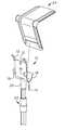
- FIG. 1is a top perspective view of an exemplary embodiment of the invention
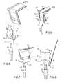
- FIG. 2is a bottom perspective view of an exemplary embodiment of the present invention
- FIG. 3is a rear view of an exemplary embodiment of the present invention.
- FIG. 4is a side view of an exemplary embodiment of the present invention.
- FIG. 5is an exploded view of an exemplary embodiment of the present invention shown in pre-interface configuration with a corner protector
- FIG. 6is a rear perspective view of an exemplary embodiment of the present invention shown in conjunction with the corner protector and a strap;
- FIG. 7is a front perspective view of an exemplary embodiment of the present invention shown with the corner protector omitting the strap for illustrative clarity;
- FIG. 8is a rear perspective view of an exemplary embodiment of the present invention shown interfacing with a hook
- FIG. 9is a front perspective view of an exemplary embodiment of the present invention shown interfacing with a chain
- FIG. 10is a front perspective view of an exemplary embodiment of the present invention shown interfacing with the chain;
- FIG. 11is a front perspective view of an exemplary embodiment of the present invention shown interfacing with the chain;
- FIG. 12is a front perspective view of an exemplary embodiment of the present invention shown interfacing with the chain;
- FIG. 13is a front perspective view of an exemplary embodiment of the present invention shown interfacing with a long strap protector
- FIG. 14is a rear perspective view of an exemplary embodiment of the present invention shown interfacing with the long strap protector;
- FIG. 15is a front perspective view of an exemplary embodiment of the present invention shown interfacing a plank board assembly.
- FIG. 16is a rear perspective view of an exemplary embodiment of the present invention shown interfacing the plank board assembly
- an embodiment of the present inventionprovides a strap corner protector multifunctional installation tool that may include a plate having a front side, a rear side, a top end and a bottom end.
- the platemay be bent into a J-shape with a curved section ending in front of the front side of the plate.
- At least two upper postsmay be attached to the top end of the plate.
- At least one lower postmay be attached to the bottom end of the plate.
- At least two back postsmay be attached to the rear side of the plate.
- a threaded protrusionmay be attached to the bottom end of the plate.
- a polemay be connected to the strap corner protector multifunctional installation tool.
- Various accessories for securing cargomay be installed and positioned through the use of the strap corner protector multifunctional installation tool.
- the strap corner protector installation tool 10may include a plate 18 .
- the plate 18may have a front side 36 , a rear side 38 , a top end 40 and a bottom end 42 .
- the plate 18may be bent in a J-shape with a curved section 44 ending in front of the front side 36 of the plate 18 .
- At least two upper posts 12may be attached to the top end 40 of the plate 18 .
- the at least two upper posts 12may be angled back away from the rear side 38 of the plate 18 .
- At least one lower post 14may be attached to the bottom end 42 of the plate 18 .
- the at least one lower post 14may be positioned along one side of the bottom end 42 of the plate 18 .
- At least two back posts 16may be attached to the rear side 38 of the plate 18 .
- the at least two back posts 16may be J-shaped.
- the at least two upper posts 12 , the at least one lower post 14 , and the at least two back posts 16may all be included in the term post.
- a threaded protrusion 20may be attached to the bottom end 42 of the plate 18 .
- the threaded protrusion 20may be approximately centrally located along the bottom end 42 of the plate 18 .
- the length of the threaded protrusion 20 and the length of the at least one lower post 14may be approximately the same.
- a pole 22may be attached to the threaded protrusion 20 on the bottom end 42 of the plate 18 .
- the pole 22may be telescopic. The pole 22 may attach to the threaded protrusion 20 by screwing the pole 22 into the threaded protrusion 20 .
- a method of making the strap corner protector installation tool 10may include the following.
- the plate 18may be cut out of a cold rolled steel sheet. A hole may be drilled into the plate 18 .
- the sheetmay be bent into a J-shape. In certain embodiments, the plate 18 may be approximately six inches long by approximately 3 . 75 inches wide.
- the upper posts 12 , the lower post 14 and the back posts 16may be cut from solid round rods.
- the threaded protrusion 20may have a female thread along an interior housing. All components may be welded together. Sharp edges may be removed.
- the strap corner protector installation tool 10may be made from aluminum, galvanized steel, stainless steel, plastic or the like.
- a method of using the strap corner protector installation tool 10may include the following.
- An objectsuch as a corner protector 24 may be removably secured into the strap corner protector installation tool 10 .
- An opening in the corner protector 24may be placed and removably secured within the curved section 44 of the plate 18 .
- a curved section of the corner protector 24may extend out from the front side 36 of the plate 18 .
- a strap 26may be held and may slide up the rear side 38 of the plate 18 in between the at least two back posts 16 and between the at least two upper posts 12 and over along the corner protector 24 extending out from the front side 36 of the plate 18 . As the strap 26 may be moved, the precision of the location may remain intact through the upper posts 12 and the back posts 16 .
- a personmay then direct the corner protector 24 to a proper location. Once the corner protector 24 may be in position, the strap corner protector installation tool 10 may be removed by holding the strap 26 and pulling down on the strap corner protector installation tool 10 . The corner protector 24 may stay in position at this time.
- an objectsuch as a long strap protector 32 may be installed using the rear side 38 of the plate 18 .
- the long strap protector 32may be removably secured in the strap corner protector installation tool 10 .
- a curved section of the long strap protector 32may face out from the rear side 38 of the plate 18 .
- a lip of the long strap protector 32may be placed in the space between the back posts 16 and the rear side 38 of the plate 18 .
- the long strap protector 32may be additionally secured in position along the strap corner protector installation tool 10 by the upper posts 12 .
- the strap 26may be placed over the long strap protector 32 . A person may then direct the long strap protector 32 to a proper location. Once the long strap protector 32 may be in position, the strap corner protector installation tool 10 may be removed by holding the strap 26 and pulling down on the strap corner protector installation tool 10 .
- the long strap protector 32may stay in position at this time.
- the strap corner protector installation tool 10may be used to route an object such as a tying chain 30 .
- the tying chain 30may be removably secured by the strap corner protector installation tool 10 .
- the tying chain 30may be placed on any of the upper posts 12 , the lower post 14 , or the back posts 16 .
- the lengths of the upper posts 12 , the lower post 14 and the back posts 16are long enough so that the tying chain 30 may be removably secured in position along the strap corner protector installation tool 10 while in motion.
- the tying chain 30may be moved to a position required.
- the strap corner protector installation tool 10may be pulled to provide tension on the tying chain 30 , rope or the like.
- the strap corner protector installation tool 10may be used for a short throw.
- An object such as a hook 28 attached to the end of a strap 26may be placed on the lower post 14 .
- the strap corner protector installation tool 10may be pulled which may pull down the hook 28 towards the user requiring no additional throws.
- the strap corner protector installation tool 10may be used to insert an object such as a plank board assembly 34 .
- a center point of the plank board assembly 34may be aligned with a center point of the strap corner protector installation tool 10 and be removably secured.
- the plank board assembly 34may be placed within the curve along the front side 36 of the plate 18 .
- the plank board assembly 34may face out away from the strap corner protector installation tool 10 .
- a personmay then direct the plank board assembly 34 to a proper location.
- the plank board assembly 34may be removed by raising the strap corner protector installation tool 10 above the area it was located and pulling the strap corner protector installation tool 10 and plank board assembly 34 away from the cargo.
Landscapes
- Engineering & Computer Science (AREA)
- Mechanical Engineering (AREA)
- Transportation (AREA)
- Package Frames And Binding Bands (AREA)
Abstract
Description
Claims (10)
Priority Applications (1)
| Application Number | Priority Date | Filing Date | Title |
|---|---|---|---|
| US14/255,795US8915685B2 (en) | 2013-04-17 | 2014-04-17 | Strap corner protector multifunctional installation tool |
Applications Claiming Priority (2)
| Application Number | Priority Date | Filing Date | Title |
|---|---|---|---|
| US201361813020P | 2013-04-17 | 2013-04-17 | |
| US14/255,795US8915685B2 (en) | 2013-04-17 | 2014-04-17 | Strap corner protector multifunctional installation tool |
Publications (2)
| Publication Number | Publication Date |
|---|---|
| US20140311092A1 US20140311092A1 (en) | 2014-10-23 |
| US8915685B2true US8915685B2 (en) | 2014-12-23 |
Family
ID=51727942
Family Applications (1)
| Application Number | Title | Priority Date | Filing Date |
|---|---|---|---|
| US14/255,795Active - ReinstatedUS8915685B2 (en) | 2013-04-17 | 2014-04-17 | Strap corner protector multifunctional installation tool |
Country Status (1)
| Country | Link |
|---|---|
| US (1) | US8915685B2 (en) |
Cited By (8)
| Publication number | Priority date | Publication date | Assignee | Title |
|---|---|---|---|---|
| US20150013116A1 (en)* | 2013-07-12 | 2015-01-15 | Samuel Lindberg | Strap Assembly And Protective Cover For A Hook Of A Strap Assembly |
| US9126521B1 (en)* | 2014-04-28 | 2015-09-08 | David McCullough | Winch supported cargo strap launching device |
| US9227552B2 (en)* | 2014-04-28 | 2016-01-05 | David McCullough | Cargo strap launching device |
| US9428096B1 (en)* | 2015-07-02 | 2016-08-30 | Terry Lee Bach | Hay strapping hook |
| US9744664B1 (en) | 2016-04-05 | 2017-08-29 | Jose Santiago | Edge protector clip kit |
| US20180361908A1 (en)* | 2017-06-15 | 2018-12-20 | Robert A. Williams | Tie-Down Management System for Securing Loads on a Vehicle Bed |
| US10618452B1 (en)* | 2019-02-20 | 2020-04-14 | Larry Coker | Cargo strap protector |
| US10850660B2 (en)* | 2015-11-17 | 2020-12-01 | Ralph Justin ABOOD | Strap locating arrangement |
Families Citing this family (8)
| Publication number | Priority date | Publication date | Assignee | Title |
|---|---|---|---|---|
| NL2012034C2 (en)* | 2013-12-30 | 2015-07-01 | Syma Logistic Tools B V | Edge protector. |
| US10099808B2 (en) | 2014-12-01 | 2018-10-16 | Signode Industrial Group Llc | Apparatus and method for forming and applying edge protectors |
| FR3035357B1 (en)* | 2015-04-23 | 2020-09-25 | Kp1 | STRAP PROTECTION KIT, ASSOCIATED PROTECTION ACCESSORY AND POSITIONING POLE |
| USD904677S1 (en)* | 2017-11-14 | 2020-12-08 | Omix-Ada, Inc. | Vehicle corner protector |
| DE102019107702B3 (en) | 2019-03-26 | 2020-05-28 | Signode Industrial Group Llc | Method for arranging an edge protection agent on a package in a device for strapping packages and device for strapping packages |
| DE102019117949B4 (en) | 2019-07-03 | 2021-05-20 | Signode Industrial Group Llc | Strapping device |
| US11801954B2 (en)* | 2019-08-14 | 2023-10-31 | Signode Industrial Group Llc | Strapping machine with improved edge-protector-positioner |
| KR102323133B1 (en)* | 2020-03-20 | 2021-11-08 | 장희규 | Device for installing of guard for goods protecter |
Citations (16)
| Publication number | Priority date | Publication date | Assignee | Title |
|---|---|---|---|---|
| US3424077A (en)* | 1967-06-12 | 1969-01-28 | Alvie L De Haan | Method for setting corner irons |
| US3469878A (en)* | 1967-06-12 | 1969-09-30 | Alvie L De Haan | Apparatus for setting corner irons |
| US3863289A (en)* | 1973-07-23 | 1975-02-04 | Richard E Whittaker | Floor mop with single use paper mopping element |
| US3936088A (en)* | 1974-07-01 | 1976-02-03 | Charles Samuel Williams | Flexible tarpaulin handling device |
| US4611512A (en)* | 1985-02-26 | 1986-09-16 | Hirosi Honda | Device for replacing fluorescent lamps |
| US4801166A (en)* | 1988-01-25 | 1989-01-31 | Cindy Jordan | Grate handle |
| USD342198S (en)* | 1991-11-30 | 1993-12-14 | Zamarripa Santiago J | Holder for hanging posters |
| US5385435A (en)* | 1991-08-01 | 1995-01-31 | Musta; Frederick A. | Tie down system and a method of using same |
| US5454611A (en)* | 1994-02-04 | 1995-10-03 | The Big Strapper Corporation | Strap installer |
| US6729358B1 (en)* | 2002-10-25 | 2004-05-04 | Greenlee Textron Inc. | Wire twisting tool |
| US6820906B1 (en) | 2002-11-15 | 2004-11-23 | Mcclendon Verlin | Hand tool for installing tie-down strap corner protector |
| US6827379B2 (en)* | 2001-11-16 | 2004-12-07 | Micro Plastics, Inc. | Quick mounting clip system for hanging decorations and Christmas lights |
| USD545648S1 (en)* | 2005-10-14 | 2007-07-03 | Robert Bosch Gmbh | Tool for holding an S-cam brake |
| US7393031B2 (en) | 2004-12-16 | 2008-07-01 | Hector Goulet | Strap launching device and method of use |
| US7900985B2 (en) | 2008-04-30 | 2011-03-08 | Carle Robert Goodfellow | Load securing extension arm |
| US8641110B1 (en)* | 2011-08-26 | 2014-02-04 | Douglas D. Perry | Multi-purpose reacher-grabber tool |
- 2014
- 2014-04-17USUS14/255,795patent/US8915685B2/enactiveActive - Reinstated
Patent Citations (16)
| Publication number | Priority date | Publication date | Assignee | Title |
|---|---|---|---|---|
| US3424077A (en)* | 1967-06-12 | 1969-01-28 | Alvie L De Haan | Method for setting corner irons |
| US3469878A (en)* | 1967-06-12 | 1969-09-30 | Alvie L De Haan | Apparatus for setting corner irons |
| US3863289A (en)* | 1973-07-23 | 1975-02-04 | Richard E Whittaker | Floor mop with single use paper mopping element |
| US3936088A (en)* | 1974-07-01 | 1976-02-03 | Charles Samuel Williams | Flexible tarpaulin handling device |
| US4611512A (en)* | 1985-02-26 | 1986-09-16 | Hirosi Honda | Device for replacing fluorescent lamps |
| US4801166A (en)* | 1988-01-25 | 1989-01-31 | Cindy Jordan | Grate handle |
| US5385435A (en)* | 1991-08-01 | 1995-01-31 | Musta; Frederick A. | Tie down system and a method of using same |
| USD342198S (en)* | 1991-11-30 | 1993-12-14 | Zamarripa Santiago J | Holder for hanging posters |
| US5454611A (en)* | 1994-02-04 | 1995-10-03 | The Big Strapper Corporation | Strap installer |
| US6827379B2 (en)* | 2001-11-16 | 2004-12-07 | Micro Plastics, Inc. | Quick mounting clip system for hanging decorations and Christmas lights |
| US6729358B1 (en)* | 2002-10-25 | 2004-05-04 | Greenlee Textron Inc. | Wire twisting tool |
| US6820906B1 (en) | 2002-11-15 | 2004-11-23 | Mcclendon Verlin | Hand tool for installing tie-down strap corner protector |
| US7393031B2 (en) | 2004-12-16 | 2008-07-01 | Hector Goulet | Strap launching device and method of use |
| USD545648S1 (en)* | 2005-10-14 | 2007-07-03 | Robert Bosch Gmbh | Tool for holding an S-cam brake |
| US7900985B2 (en) | 2008-04-30 | 2011-03-08 | Carle Robert Goodfellow | Load securing extension arm |
| US8641110B1 (en)* | 2011-08-26 | 2014-02-04 | Douglas D. Perry | Multi-purpose reacher-grabber tool |
Cited By (10)
| Publication number | Priority date | Publication date | Assignee | Title |
|---|---|---|---|---|
| US20150013116A1 (en)* | 2013-07-12 | 2015-01-15 | Samuel Lindberg | Strap Assembly And Protective Cover For A Hook Of A Strap Assembly |
| US9481285B2 (en)* | 2013-07-12 | 2016-11-01 | Samuel Lindberg | Strap assembly and protective cover for a hook of a strap assembly |
| US9126521B1 (en)* | 2014-04-28 | 2015-09-08 | David McCullough | Winch supported cargo strap launching device |
| US9227552B2 (en)* | 2014-04-28 | 2016-01-05 | David McCullough | Cargo strap launching device |
| US9428096B1 (en)* | 2015-07-02 | 2016-08-30 | Terry Lee Bach | Hay strapping hook |
| US10850660B2 (en)* | 2015-11-17 | 2020-12-01 | Ralph Justin ABOOD | Strap locating arrangement |
| US9744664B1 (en) | 2016-04-05 | 2017-08-29 | Jose Santiago | Edge protector clip kit |
| US20180361908A1 (en)* | 2017-06-15 | 2018-12-20 | Robert A. Williams | Tie-Down Management System for Securing Loads on a Vehicle Bed |
| US10688909B2 (en)* | 2017-06-15 | 2020-06-23 | Robert A. Williams | Tie-down management system for securing loads on a vehicle bed |
| US10618452B1 (en)* | 2019-02-20 | 2020-04-14 | Larry Coker | Cargo strap protector |
Also Published As
| Publication number | Publication date |
|---|---|
| US20140311092A1 (en) | 2014-10-23 |
Similar Documents
| Publication | Publication Date | Title |
|---|---|---|
| US8915685B2 (en) | Strap corner protector multifunctional installation tool | |
| US10138681B2 (en) | Ladder tie off system | |
| US8286572B1 (en) | Fishing rod holding system | |
| US10161186B1 (en) | Ladder securing device | |
| US9421917B1 (en) | Equipment holder for workers and safety, rescue and disaster crews | |
| CN102316939B (en) | Pole safety assembly | |
| US9874039B2 (en) | Sheet material fastener device | |
| US9359779B2 (en) | Space saving anchor point for a concrete structure | |
| EP2378032B1 (en) | Soft net containment | |
| US9393980B2 (en) | Tow plate shelf device | |
| US9353535B2 (en) | Space saving anchor point for a concrete structure | |
| US10422181B2 (en) | Extendible barricade | |
| US6397865B1 (en) | Tie-downs for a table umbrella | |
| US5884890A (en) | Spring loaded CB antenna mount | |
| US10088135B2 (en) | Mounting base for work light | |
| US10030396B2 (en) | System to deter external climbing of open stairs | |
| US20150369421A1 (en) | Bracket and Lifting/Lowering Device Assembly | |
| US6786010B1 (en) | Outdoor storage structure | |
| JP3217294U (en) | Rope locking device | |
| US8157283B1 (en) | Fifth wheel release tool apparatus | |
| JP5380110B2 (en) | fence | |
| US20150360598A1 (en) | Truck bed extender device | |
| US20140020980A1 (en) | Hand grip assembly | |
| US9353934B1 (en) | Structure lighting assembly | |
| CA2505271A1 (en) | Cable bracket mechanism |
Legal Events
| Date | Code | Title | Description |
|---|---|---|---|
| FEPP | Fee payment procedure | Free format text:MAINTENANCE FEE REMINDER MAILED (ORIGINAL EVENT CODE: REM.) | |
| LAPS | Lapse for failure to pay maintenance fees | Free format text:PATENT EXPIRED FOR FAILURE TO PAY MAINTENANCE FEES (ORIGINAL EVENT CODE: EXP.); ENTITY STATUS OF PATENT OWNER: MICROENTITY | |
| STCH | Information on status: patent discontinuation | Free format text:PATENT EXPIRED DUE TO NONPAYMENT OF MAINTENANCE FEES UNDER 37 CFR 1.362 | |
| FP | Lapsed due to failure to pay maintenance fee | Effective date:20181223 | |
| FEPP | Fee payment procedure | Free format text:PETITION RELATED TO MAINTENANCE FEES FILED (ORIGINAL EVENT CODE: PMFP); ENTITY STATUS OF PATENT OWNER: MICROENTITY | |
| MAFP | Maintenance fee payment | Free format text:PAYMENT OF MAINTENANCE FEE, 4TH YEAR, MICRO ENTITY (ORIGINAL EVENT CODE: M3551); ENTITY STATUS OF PATENT OWNER: MICROENTITY Year of fee payment:4 | |
| FEPP | Fee payment procedure | Free format text:PETITION RELATED TO MAINTENANCE FEES DISMISSED (ORIGINAL EVENT CODE: PMFS); ENTITY STATUS OF PATENT OWNER: MICROENTITY | |
| FEPP | Fee payment procedure | Free format text:PETITION RELATED TO MAINTENANCE FEES FILED (ORIGINAL EVENT CODE: PMFP); ENTITY STATUS OF PATENT OWNER: MICROENTITY | |
| FEPP | Fee payment procedure | Free format text:PETITION RELATED TO MAINTENANCE FEES GRANTED (ORIGINAL EVENT CODE: PMFG); ENTITY STATUS OF PATENT OWNER: MICROENTITY | |
| PRDP | Patent reinstated due to the acceptance of a late maintenance fee | Effective date:20200831 | |
| STCF | Information on status: patent grant | Free format text:PATENTED CASE | |
| FEPP | Fee payment procedure | Free format text:MAINTENANCE FEE REMINDER MAILED (ORIGINAL EVENT CODE: REM.); ENTITY STATUS OF PATENT OWNER: MICROENTITY | |
| FEPP | Fee payment procedure | Free format text:SURCHARGE FOR LATE PAYMENT, MICRO ENTITY (ORIGINAL EVENT CODE: M3555); ENTITY STATUS OF PATENT OWNER: MICROENTITY | |
| MAFP | Maintenance fee payment | Free format text:PAYMENT OF MAINTENANCE FEE, 8TH YEAR, MICRO ENTITY (ORIGINAL EVENT CODE: M3552); ENTITY STATUS OF PATENT OWNER: MICROENTITY Year of fee payment:8 |