US8915434B2 - Fraud prevention - Google Patents
Fraud preventionDownload PDFInfo
- Publication number
- US8915434B2 US8915434B2US13/099,836US201113099836AUS8915434B2US 8915434 B2US8915434 B2US 8915434B2US 201113099836 AUS201113099836 AUS 201113099836AUS 8915434 B2US8915434 B2US 8915434B2
- Authority
- US
- United States
- Prior art keywords
- card reader
- card
- protrusion
- customer
- alien
- Prior art date
- Legal status (The legal status is an assumption and is not a legal conclusion. Google has not performed a legal analysis and makes no representation as to the accuracy of the status listed.)
- Active, expires
Links
Images


Classifications
- G—PHYSICS
- G07—CHECKING-DEVICES
- G07F—COIN-FREED OR LIKE APPARATUS
- G07F19/00—Complete banking systems; Coded card-freed arrangements adapted for dispensing or receiving monies or the like and posting such transactions to existing accounts, e.g. automatic teller machines
- G07F19/20—Automatic teller machines [ATMs]
- G07F19/205—Housing aspects of ATMs
- G07F19/2055—Anti-skimming aspects at ATMs
Definitions
- the present inventionrelates to fraud prevention.
- the inventionrelates to preventing unauthorized reading of data from a card.
- card skimmingUnauthorized reading of card data, such as data encoded on a magnetic stripe card, while the card is being used (hereafter “card skimming”), is a known type of fraud. Card skimming is typically perpetrated by adding a magnetic read head (hereafter “alien reader”) to a fascia of an automated teller machine (ATM) to read a magnetic stripe on a customer's card as the customer inserts or (more commonly) retrieves the card from an ATM. The customer's personal identification number (PIN) is also ascertained when the customer uses the ATM.
- ATMautomated teller machine
- Examples of how this is achievedinclude: a video camera that captures images of the PINpad on the ATM, a false PINpad overlay that captures the customer's PIN, or a third party watching the customer (“shoulder surfing”) as he/she enters his/her PIN.
- the third partycan then create a card using the card data read by the alien reader, and can withdraw funds from the customer's account using the created card and the customer's PIN (ascertained by one of the ways described above).
- One methodinvolves transmitting an electromagnetic signal (hereafter a “jamming signal”) when the card is being transported so that the alien reader cannot detect the magnetically encoded data because of the presence of the jamming signal.
- a jamming signalan electromagnetic signal
- This techniquecan be effective, it is possible to filter out the jamming signal so that the magnetically encoded data from the customer's card can be detected.
- signal processingto cancel out a jamming signal by using another alien reader that receives only the jamming signal and uses this as a reference signal.
- the reference signalis used to cancel out the jamming signal by subtracting the reference signal from the composite signal (comprising the reference signal and the magnetic signal representing account data from the data card) to reveal the account data signal.
- Using a jamming signalalso has some disadvantages. If too powerful a signal is used, then there are concerns that the jamming signal could interfere with medical devices, such as heart pacemakers.
- the inventiongenerally provides methods, systems, apparatus, and software for providing improved fraud prevention.
- a card reader guidefor use in a fascia of a self-service terminal, the card reader guide comprising:
- a card reader apertureextending in a first direction through which a customer may insert a data card
- a first protrusionextending (i) along part of the card reader aperture through which a magnetic stripe of the card passes, and (ii) towards the customer, wherein the first protrusion defines a stripe path in registration with the magnetic stripe of the card as the card is inserted by the customer;
- a second protrusionopposite to, and aligned with, the first protrusion, and extending (i) along the part of the card reader aperture through which the magnetic stripe of the card passes, and (ii) towards the customer;
- a magnetic reader detectorlocated in the first protrusion at the stripe path.
- the card reader guidemay further comprise a shielding plate coupled thereto and located behind the card reader aperture so that the magnetic reader detector does not detect any components within the self-service terminal (SST).
- the shielding platemay comprise a metal, a metal alloy, a plastics material having a conducting coating, or the like. The shielding plate prevents metal components within the SST being detected as alien card readers. For example, if a motorized card reader within the SST is moved closer to the card reader aperture than usual (for example, after a service operation), then this may (incorrectly) be detected as an alien device.
- the shielding devicepreferably includes an aperture through which the data cards can be transported between the card reader guide and a card reader within the SST.
- a signal generator circuitmay be located in the second protrusion.
- the shielding devicemay define a plurality of apertures for routing cables therethrough, such as cables extending between the magnetic reader detector and a controller card coupled to an SST controller, and between the signal generator circuit and the controller card.
- the magnetic reader detectormay comprise a capacitive sensor.
- the capacitive sensormay comprise a transmit plate spatially separated from a receive plate by a ground strip.
- the ground stripmay have a longitudinal shape and may extend transversely to the card reader aperture and towards the customer.
- the ground stripmay be in registration with the stripe path.
- the ground stripmay be in registration with a track two portion of the stripe path.
- the capacitive sensormay receive an alternating voltage on the transmit plate
- a self-service terminal(SST) incorporating the card reader guide according to the first aspect.
- the SSTmay include a card reader.
- the card reader guidemay be removably coupled to an SST fascia.
- the self-service terminalmay be an automated teller machine (ATM), an information kiosk, a financial services centre, a bill payment kiosk, a lottery kiosk, a postal services machine, a check-in and/or check-out terminal such as those used in the retail, hotel, car rental, gaming, healthcare, and airline industries, and the like.
- ATMautomated teller machine
- information kioska financial services centre
- bill payment kioska bill payment kiosk
- lottery kioska lottery kiosk
- postal services machinea check-in and/or check-out terminal such as those used in the retail, hotel, car rental, gaming, healthcare, and airline industries, and the like.
- the first protrusionmay be located beneath the second protrusion. Alternatively, the first protrusion may be located above the second protrusion. In some embodiments, the card reader slot may extend vertically (or at least not horizontally) so the first and second protrusions may be laterally (or even diagonally) offset.
- the first and second protrusionmay extend by the same amount (or nearly the same amount) from the card reader aperture as a card is ejected by the card reader, so that the customer must place his/her fingers on the part of the card that is not enclosed by the first and second protrusions.
- Thisalso has the advantage that it is more difficult to place a magnetic reader (that is, an alien reader) at the end of one of the protrusions without the customer noticing that there is an alien device present.
- a magnetic readerthat is, an alien reader
- protrusionsto cover the part of a card having the magnetic stripe is in contrast to known card reader guides where the protrusions extend along a part of the card that does not have a magnetic stripe so that the customer can only grasp the card by the portion carrying the stripe.
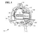
- FIG. 1is a pictorial diagram of a rear perspective view of a card reader guide according to one embodiment of the present invention
- FIG. 2is an exploded pictorial diagram illustrating components of the card reader guide of FIG. 1 ;
- FIG. 3is a front perspective view of one part (the card reader guide cover) of the card reader guide of FIG. 1 ;
- FIG. 4is a rear perspective view of the card reader guide cover of FIG. 3 ;
- FIG. 5is a pictorial plan view of part (the magnetic reader detector) of one of the components of the card reader guide shown in FIG. 2 ;
- FIG. 6is a pictorial perspective view of the card reader guide of FIG. 1 , with the card reader guide cover of FIG. 3 shown as partially transparent to reveal the magnetic reader detector of FIG. 5 ;
- FIG. 7is a pictorial plan view of another part (the signal generator) of one of the components of the card reader guide shown in FIG. 2 ;
- FIG. 8is a pictorial perspective view of the signal generator of FIG. 7 ;
- FIG. 9is a simplified schematic view of a fascia of a self-service terminal incorporating the card reader guide of FIG. 1 ;
- FIG. 10is a block diagram of a controller for controlling the operation of the magnetic reader detector of FIG. 5 and the signal generator of FIG. 7 .
- FIG. 1is a pictorial diagram of a rear perspective view of a card reader guide 10 according to one embodiment of the present invention.
- the card reader guide 10comprises a card reader guide cover 12 defining three apertured tabs 14 by which the card reader guide cover 12 is coupled to a rear part of a fascia (not shown in FIG. 1 ) of an SST.
- the card reader guide 10further comprises a shielding plate 20 coupled to the card reader guide cover 12 by three screws 22 a,b,c.
- FIG. 2is an exploded pictorial diagram illustrating components of the card reader guide 10 .
- FIG. 2illustrates a magnetic reader detector 30 and a signal generator 40 .
- FIG. 2also shows a data card 42 (in the form of a magnetic stripe card) aligned with the card reader guide 10 .
- the card reader guide 10is operable to receive the magnetic stripe card 42 , which is inserted by a customer.
- a magnetic stripe cardhas a large planar area (the length and width) on each of two opposing sides and a four thin edges therebetween. Two of these edges (front and rear) 43 a,b are narrower than the other two edges (the side edges) 44 a,b .
- the magnetic stripe side (the lower side) of a cardrefers to the large planar area that carries a magnetic stripe 45 (shown in broken line in FIG. 2 ).
- the magnetic stripe 45is disposed parallel to the side edges 44 a,b.
- the magnetic stripe sideOpposite the magnetic stripe side (the upper side 47 ) there is a large planar area that (typically) does not carry a magnetic stripe 45 , but typically includes account and customer information embossed thereon. On some cards, the upper side 47 may carry integrated circuit contacts. On the magnetic stripe side of the card, the magnetic stripe 45 is not centrally located; rather, it is located nearer to one of the side edges (referred to as the magnetic stripe edge 44 a ) than to the other side edge (referred to as the non-magnetic stripe edge 44 b ).
- FIGS. 3 and 4are front and rear perspective views, respectively, of the card reader guide cover 12 .
- the card reader guide cover 12comprises a moulded plastics part dimensioned to be accommodated within, and partially protrude through, an aperture in a fascia (not shown in FIG. 2 ).
- the card reader guide 10defines a card slot 50 extending generally horizontally across the guide 10 in the direction of centre line 52 , from a non-stripe end 54 to a stripe end 56 .
- the magnetic stripe 45 on the magnetic stripe card 42is located closer to the stripe end 56 than to the non-stripe end 54 .
- the card reader guide 10defines a breakout line 58 extending generally vertically (perpendicular to the card reader slot 50 ).
- the card reader guide 10also defines a first (lower) protrusion 60 .
- the first (lower) protrusion 60includes a planar section 62 across which the magnetic stripe side of a card passes as the card 42 is inserted.
- the first (lower) protrusion 60also includes an upright section 64 that extends from the breakout line 58 to an end surface 66 .
- the end surface 66is spaced from the card slot 50 to ensure that card does not protrude beyond the end surface 66 when ejected by a card reader (not shown in FIGS. 2 to 4 ) within the SST.
- a magnetic stripe path 68is defined on the planar section 62 . This is the portion of the planar section 62 that the magnetic stripe 45 on a correctly inserted data card 42 will be in registration with when the card 42 is inserted or removed by a customer.
- the magnetic stripe path 68is centered on track two of a magnetic stripe. It is track two that carries the customer account information for the data card 42 , so track two is the track that alien readers attempt to read.
- the first protrusion 60also defines a cavity (best seen in FIG. 4 and shown generally by arrow 70 ), which is referred to herein as the “detector cavity”, and which is beneath the planar section 62 and within the card reader guide cover 12 .
- the card reader guide 10defines a second (upper) protrusion 80 similar to, aligned with, and opposite the first protrusion 60 .
- the second (upper) protrusion 80includes a planar section 82 (best seen in FIG. 4 ) beneath which a magnetic stripe side of a card 42 passes as the card 42 is inserted.
- the second (upper) protrusion 80also includes an upright section 84 that extends from the breakout line 58 to an end surface 86 .
- the second protrusion 80defines a cavity 90 (referred to herein as the “signal generator cavity”) above the planar section 82 and within the card reader guide cover 12 .
- the magnetic reader detector 30is dimensioned to be accommodated within the detector cavity 70 and is mounted therein by two screws 102 that engage with the card reader guide 10 .
- the magnetic reader detector 30includes a communication cable 104 for routing signals and power between the magnetic reader detector 30 and an external controller (not shown in FIG. 2 ). Such a controller would typically be located in an SST in which the card reader guide 10 is installed.
- the signal generator 40is dimensioned to be accommodated within the signal generator cavity 90 and is mounted therein by two screws 106 that engage with the card reader guide 10 .
- the signal generator 40also includes an output cable 108 for routing signals and power between the signal generator 40 and the external controller (not shown in FIG. 2 ).
- a drainage pipe 109is also provided to drain away any water ingress from the card slot 50 .
- FIG. 5is a pictorial plan view of part of the magnetic reader detector 30 .
- the magnetic reader detector 30comprises a track printed circuit board (pcb) 110 on which is disposed part of a capacitive sensor 112 and an electronic drive circuit (not shown in FIG. 5 ) located beneath the track pcb 110 .
- pcbtrack printed circuit board
- the magnetic reader detector 30is physically configured to conform to the shape of the detector cavity 70 so that when the magnetic reader detector 30 is inserted into the detector cavity 70 the track pcb 110 fits securely in place.
- the capacitive sensor 112operates in a similar way to a capacitive proximity sensor, as will now be described.
- the capacitive sensor 112comprises a transmit plate 114 separated from a receive plate 115 by a linear track (a ground strip) 116 .
- the transmit plate 114 , receive plate 115 , and ground strip 116are all defined as conducting tracks on the track pcb 110 .
- the ground strip 116is located on the track pcb 110 such that when the magnetic reader detector 30 is inserted into the lower protrusion 60 of the card reader guide 10 , the ground strip 116 is in registration with the magnetic stripe path 68 . In particular, the ground strip 116 is aligned with track two of the magnetic stripe path 68 . This is illustrated in FIG. 6 , which is a pictorial perspective view of the card reader guide 10 , with the card reader guide cover 12 shown as partially transparent to reveal the magnetic reader detector 30 .
- the capacitive sensor 112operates by transmitting an alternating signal on the transmit plate 114 , which creates an electric field between the transmit plate 114 and the receive plate 115 that arches over the ground strip 116 , the air gap in the arch providing the dielectric. If a material (such as an alien reader, or a data card) is inserted into this electric field then the dielectric changes, which changes the phase and magnitude of the electric field. This is detected by the receive plate 115 .
- a materialsuch as an alien reader, or a data card
- Drive and signal processing circuitry(not shown in FIG. 5 ) is located on a drive pcb 117 (located beneath the track pcb 110 , as shown in FIG. 6 ) to provide the alternating signal and detect the phase and magnitude changes.
- the geometry, configuration, and location of the transmit plate 114 , receive plate 115 , and ground strip 116optimizes the probability of the capacitive sensor 112 detecting an alien reader, because any alien reader must be located at a point over which track two of the card's magnetic stripe will pass, and the electric field is located along this path.
- the track pcb 110also includes two magnetic sensors 118 a,b mounted on an underside thereof.
- the communication cable 104conveys one signal from each of the two magnetic sensors 118 , power to supply the capacitive sensor 112 , and one response signal from the capacitive sensor 112 .
- FIGS. 7 and 8are a pictorial plan view and perspective view respectively, of part of the signal generator 40 shown relative to the magnetic stripe path 68 .
- the signal generator 40comprises a pair of inductive coil drives 120 a,b .
- Each inductive drive coil 120 a,bcomprises a generally C-shaped (when viewed from the side) ferrite core 122 a,b having opposing poles (north pole 124 a,b (only 124 a is shown) and south pole 126 a,b ) at opposite ends, and being wound with wire 128 a,b at a central portion.
- Each inductive coil drive 120 a,bis driven by a signal from the external controller (not shown in FIGS. 7 and 8 ).
- the C-shape of the ferrite coresensures that most of the electromagnetic field generated by the inductive coil drives 120 a,b extends downwards towards the magnetic stripe path 68 , rather than upwards.
- Each of the inductive coil drives 120 a,bis aligned with the magnetic stripe path 68 but the two inductive coil drives are longitudinally offset relative to each other (as shown in FIG. 7 ).
- the two inductive coils 120 a,bdo not generate a symmetric electromagnetic field. This longitudinal offsetting makes it more difficult for a fraudster to filter out the combined signal from the two inductive coil drives 120 a,b.
- One of the two magnetic sensors 118 a,bis in registration with a centre point between the poles 124 a , 126 a of the first ferrite core 122 a
- the other of the two magnetic sensors 118 bis in registration with a centre point between the poles of the second ferrite core 122 b .
- Each of the two magnetic sensors 118 a,bmeasures the magnetic signal present. If the two inductive coils 120 a,b are active then a large magnetic signal should be detected by each of the two magnetic sensors 118 a,b.
- FIG. 9is a pictorial diagram of a fascia 140 of an SST 150 that includes the card reader guide 10 , and shows the data card 42 partially inserted therein.
- a motorized card reader 170(illustrated in broken line) is aligned with, and located behind, the card reader guide 10 so that a card transport path (not shown in FIG. 9 ) in the card reader 170 aligns with the card slot 50 of the card reader guide 10 .
- the card reader 170includes a card reader controller 172 for controlling operation of the card reader 170 .
- the motorized card readeris from Sankyo Seiki Mfg Ltd at 1-17-2, Shinbashi, Minato-Ku, Tokyo, 1058633, Japan.
- any other convenient motorized card readercould be used.
- the SSTalso includes an SST controller 174 , which includes a card guide control circuit 180 implemented as an expansion board that slots into a motherboard (not shown) on which a processor 182 is mounted.
- the processor 182executes an SST control program 184 .
- the SST control program 184controls the operation of the SST, including communicating with modules such as the card reader 170 , and presenting a sequence of screens to a customer to guide the customer through a transaction.
- FIG. 10is a simplified block diagram of the card guide control circuit 180 that is used to control the electronic components in the card reader guide 10 and to indicate if an alien reader may be present.
- the control circuit 180receives five inputs. Three of these inputs are fed into a detector 190 , the other two inputs are fed into a monitor 200 .
- One of the detector inputs (the width switch status) 202indicates the status of a width switch (not shown) on the card reader 170 . As is known in the art, when the width switch is closed, this indicates that an object inserted into the card reader 170 has a width that matches that of a standard data card.
- Another of the detector inputs (the shutter status) 204indicates the status of a shutter (not shown) in the card reader 170 .
- the shuttercan either be open or closed and controls access to a card reader path within the card reader 170 .
- the shutter 170is only opened by the card reader controller 172 ( FIG. 9 ) within the card reader 170 if the width switch is closed and a magnetic pre-read head (not shown) in the card reader 170 detects a magnetic stripe.
- the pre-read headis used to ensure that a data card has been inserted in the correct orientation.
- the third detector input (from the capacitive sensor 112 ) 206indicates the state of the output signal from the capacitive sensor 112 .
- the capacitive sensor input 206indicates whether an object is present in the vicinity of the magnetic stripe path 68 .
- the two inputs 210 , 212(referred to as magnetic signal inputs) that are fed into the monitor 200 are from the two magnetic sensors 118 a,b . These magnetic signal inputs 210 , 212 indicate the presence of a magnetic signal at each of the two magnetic sensors 118 a,b respectively.
- the detector 190includes logic circuitry and provides an active output 220 (referred to as the jam signal) when the width switch is open (the width switch status input 202 is active), the shutter is open (the shutter status input 204 is active), and an alien object is detected by the capacitive sensor input 206 .
- the control circuit 180generates a jamming signal. This should occur every time a card is inserted by a customer because the inserted card changes the dielectric value of the air gap above the capacitive sensor 112 .
- the jam signal 220is fed into a random number generator circuit 230 (which may generate truly random or pseudo random numbers). Random number generating circuits are well-known to those of skill in the art so will not be described herein in detail.
- the random number generator circuit 230provides two outputs: a first random signal 232 and a second random signal 234 . These two outputs 232 , 234 (which convey different random signals) are fed into a coil driver circuit 240 .
- the coil driver circuit 240generates two base signals (a first base signal and a second base signal), each centered on approximately 2 kHz.
- the coil driver circuit 240applies the first random signal 232 to the first base signal; and the second random signal 234 to the second base signal, and outputs these as a first drive signal 242 and a second drive signal 244 respectively.
- the random signalsare in the form of a bit pattern sequence.
- the coil driver circuit 240uses the random signals (the bit pattern sequences) to change the duty cycle of each of the first and second base signals. That is, the random signals are used to provide pulse width modulation of the 2 kHz signals.
- the important pointis that the random signals 232 , 234 are used to impart some randomness to the regular (2 kHz) base signals. This randomness may comprise pulse width modulation, amplitude modulation, superimposing a high frequency component on a base signal, or any other convenient technique. This added randomness makes it much more difficult to filter out the signals.
- the first drive signal 242is output to the first inductive coil drive 120 a ; and the second drive signal 244 is output to the second inductive coil drive 120 b .
- the first and second drive signals 242 , 244are the signals that drive the inductive coil drives 120 a,b.
- the first and second drive signals 242 , 244are also output to the monitor 200 .
- the main purpose of the monitor 200is to ensure that the magnetic reader detector 30 is not being (i) jammed by an external signal, or (ii) screened so that it does not detect an alien reader.
- the monitor 200continually monitors the two magnetic signal inputs 210 , 212 from the two magnetic sensors 118 a,b . As mentioned above, these magnetic signal inputs 210 , 212 indicate the presence of magnetic signals at the two magnetic sensors 118 a,b.
- the monitor 200correlates these two magnetic signal inputs 210 , 212 with the jam signal 220 . Due to time delays in creating an electro-magnetic field at the coil drives 120 , there will be a short delay between each of the coil drive signals 242 , 244 going active, and the two magnetic sensors 118 a,b detecting a magnetic field. Hence there will be a delay between the coil drive signals 242 , 244 going active and the magnetic signal inputs 210 , 212 going active. Similarly, when the coil drive signals 242 , 244 go inactive, there will be a short delay before the magnetic signal inputs 210 , 212 go inactive.
- the monitor 200detects that a magnetic signal input 210 , 212 is active at the instant when the associated coil drive signal 242 , 244 has just transitioned to active, then this may indicate that a third party is attempting to jam the magnetic reader detector 30 . This is because there should be a time delay between the coil drive signal 242 , 244 going active and an electro-magnetic field being detected. If there is no time delay, then the magnetic signal input 210 , 212 that was detected as active must have been active before the coil drive signal was activate. If such an event occurs on “m” consecutive occasions, then the monitor 200 activates a jam attack output 252 .
- the jam attack output 252indicates that an electromagnetic field is present that was not generated by the coil drives 120 a,b . In this embodiment, “m” is four, so the jam attack output 252 is activated if this condition occurs on four consecutive occasions.
- the monitor 200detects that a magnetic signal input 210 , 212 is inactive at the instant when the associated coil drive signal 242 , 244 has just transitioned to inactive, then this may indicate that a third party is attempting to shield (or screen) the magnetic reader detector 30 from the electromagnetic field generated by the coil drives 120 a,b . This is because there should be a time delay (a time lag) between the coil drive signal 242 , 244 going inactive and the electro-magnetic field generated by those coil drives 120 a,b reducing to zero. If there is no time delay, then the magnetic signal input 210 , 212 that was detected as inactive must have been inactive before the coil drive signal was inactivated.
- a time delaya time lag
- the monitor 200activates a weak output 254 .
- the weak attack output 254indicates that no electromagnetic field is present even though the coil drives 120 a,b are generating (or attempting to generate) an electromagnetic field. This may indicate that a third party is attempting to shield (or screen) the two inductive coil drives 120 a,b to prevent them from jamming an alien reader.
- “n”is four, so the weak output 254 is activated if this condition occurs on four consecutive occasions.
- both of the magnetic sensors 118 a,bdetect magnetic signals that correlate with the first and second drive signals 242 , 244 , then the monitor 200 activates a normal (OK) output 256 to indicate that the correct jamming signals have been detected from the inductive coil drives 120 a,b .
- both of the magnetic sensors 118 a,bdetect magnetic signals that are correctly offset from the first and second drive signals 242 , 244 respectively, then the monitor 200 activates the normal output 256 .
- correctly offsetmeans that there is a time delay between each of the magnetic signal sensors 118 a,b and its associated first and second drive signal 242 , 244 that corresponds to an expected time delay.
- the card guide circuit 180also includes a local processor 260 including firmware 262 .
- the firmware 262interfaces with the logic circuitry in the card guide circuit 180 , and communicates with the SST control program 184 via a USB interface 264 .
- the local processor 260receives the three outputs 252 , 254 , 256 from the monitor 200 and also the jam signal 220 , and the firmware 262 decides whether to raise an alarm based on the status of these signals.
- the firmware 262may transmit an alarm signal if the jam signal 220 is active for longer than a predetermined length of time, for example, one minute, or if either of the weak output 254 or the jam attack output 252 is active, or if either of the weak output 254 or the jam attack output 252 is active for longer than a predetermined time (for example, five seconds).
- the firmware 262communicates with the SST control program 184 and provides an alarm signal (which may be active or inactive) thereto over the USB interface 264 . This enables the SST control program 184 to take action if the alarm signal is active.
- the firmware 262may also include a simple network management protocol (SNMP) agent (not shown) that transmits a trap to a remote management centre (not shown) if the alarm signal is set active by the firmware 262 .
- SNMPsimple network management protocol
- the width switchis closed and the pre-read head detects the magnetic stripe 45 on the underside of the card 42 .
- the card reader 170then opens the shutter.
- the capacitive sensor input 206indicates that an object (the data card 42 ) is present. This combination causes the detector 190 to activate the jam signal 220 .
- the active jam signal 220causes the random number generator 230 to generate the first and second random signals 232 , 234 , which the coil driver 240 applies to the first and second base signals to generate the first and second drive signals 242 , 244 , which now have different duty cycles. These signals 242 , 244 are used to power the inductive coil drives 120 a,b respectively, which create electromagnetic fields around the data card 42 .
- the random signals 232 , 234are continuous bit streams that are applied to the base signals as the base signals are being generated.
- the monitor 200attempts to correlate the two inputs 210 , 212 from the two magnetic sensors 118 a,b with the first and second drive signals 242 , 244 .
- the monitor 200activates the normal (OK) output 256 .
- the monitor 200records this as a potential jam and increments a counter. If this occurs four times in succession, then the monitor 200 activates the jam attack output 252 . If this does not happen four times in succession, for example, on the third occasion the status is correct, then the monitor 200 resets the counter.
- the monitor 200records this as a potential shielding attack and increments a counter. If this occurs four times in succession, then the monitor 200 activates the weak output 254 . If this does not happen four times in succession, for example, on the third occasion the status is correct, then the monitor 200 resets the counter.
- the card guide control circuit 180raises an alarm, causing the SST controller 174 to complete any current transaction, return the data card 42 to the customer, then put the SST 150 out of service and send an alarm signal to a remote management centre (not shown) to request a visit from a service engineer.
- the number of inductive coil drives 120may be more or less than two.
- the inductive coil drives 120may be driven at a frequency other than 2 kHz.
- the number of times in succession that a correlation must be incorrect before the appropriate signal is activatedmay be more or less than four, and may differ for the jam attack output and the weak output.
- control circuit 180may include a built-in alarm.
- the shape of the protrusionsmay differ from those described above.
Landscapes
- Business, Economics & Management (AREA)
- Accounting & Taxation (AREA)
- Finance (AREA)
- Physics & Mathematics (AREA)
- General Physics & Mathematics (AREA)
- Control Of Vending Devices And Auxiliary Devices For Vending Devices (AREA)
Abstract
Description
Claims (18)
Priority Applications (1)
| Application Number | Priority Date | Filing Date | Title |
|---|---|---|---|
| US13/099,836US8915434B2 (en) | 2011-05-03 | 2011-05-03 | Fraud prevention |
Applications Claiming Priority (1)
| Application Number | Priority Date | Filing Date | Title |
|---|---|---|---|
| US13/099,836US8915434B2 (en) | 2011-05-03 | 2011-05-03 | Fraud prevention |
Publications (2)
| Publication Number | Publication Date |
|---|---|
| US20120280033A1 US20120280033A1 (en) | 2012-11-08 |
| US8915434B2true US8915434B2 (en) | 2014-12-23 |
Family
ID=47089572
Family Applications (1)
| Application Number | Title | Priority Date | Filing Date |
|---|---|---|---|
| US13/099,836Active2031-07-20US8915434B2 (en) | 2011-05-03 | 2011-05-03 | Fraud prevention |
Country Status (1)
| Country | Link |
|---|---|
| US (1) | US8915434B2 (en) |
Cited By (13)
| Publication number | Priority date | Publication date | Assignee | Title |
|---|---|---|---|---|
| US20170249808A1 (en)* | 2016-02-27 | 2017-08-31 | Raymond Markase | Anti-skimming Device |
| US20180060578A1 (en)* | 2016-08-29 | 2018-03-01 | Mfs Corporation | Magnetic stripe card anti-hacking method and device |
| US10810475B1 (en) | 2019-12-20 | 2020-10-20 | Capital One Services, Llc | Systems and methods for overmolding a card to prevent chip fraud |
| US10817768B1 (en) | 2019-12-20 | 2020-10-27 | Capital One Services, Llc | Systems and methods for preventing chip fraud by inserts in chip pocket |
| US10891819B2 (en) | 2012-10-01 | 2021-01-12 | Jcm American Corporation | Bezel assembly for use with an automated transaction device |
| US10888940B1 (en) | 2019-12-20 | 2021-01-12 | Capital One Services, Llc | Systems and methods for saw tooth milling to prevent chip fraud |
| US10977539B1 (en) | 2019-12-20 | 2021-04-13 | Capital One Services, Llc | Systems and methods for use of capacitive member to prevent chip fraud |
| US11049822B1 (en) | 2019-12-20 | 2021-06-29 | Capital One Services, Llc | Systems and methods for the use of fraud prevention fluid to prevent chip fraud |
| US11227461B2 (en) | 2012-10-01 | 2022-01-18 | Jcm American Corporation | Bezel assembly with close range communication abilities for use with an automated transaction device |
| US11295319B2 (en) | 2020-05-26 | 2022-04-05 | Ncr Corporation | Fraud detection system and method |
| US11475741B1 (en) | 2021-07-19 | 2022-10-18 | Ncr Corporation | Fraud detection system and method |
| US11715103B2 (en) | 2020-08-12 | 2023-08-01 | Capital One Services, Llc | Systems and methods for chip-based identity verification and transaction authentication |
| US12443821B2 (en) | 2024-04-15 | 2025-10-14 | Capital One Services, Llc | Systems and methods for use of capacitive member to prevent chip fraud |
Families Citing this family (7)
| Publication number | Priority date | Publication date | Assignee | Title |
|---|---|---|---|---|
| US20090159682A1 (en) | 2007-12-24 | 2009-06-25 | Dynamics Inc. | Cards and devices with multi-function magnetic emulators and methods for using same |
| US8584947B2 (en)* | 2011-09-13 | 2013-11-19 | Ncr Corporation | Fraud prevention |
| US10410458B2 (en) | 2012-10-01 | 2019-09-10 | Jcm American Corporation | Bezel assembly for use with an automated transaction device |
| CN106030669B (en)* | 2013-09-22 | 2019-09-20 | Jcm美国公司 | Front frame assembly for use with automated trading equipment |
| CN105590376B (en)* | 2016-02-03 | 2018-11-02 | 江苏国光信息产业股份有限公司 | Multifunctional service accepting terminal |
| US20200027299A1 (en)* | 2018-07-17 | 2020-01-23 | Revolution Retail Systems Llc | Metal detection systems and methods |
| JP7749401B2 (en)* | 2021-10-18 | 2025-10-06 | ニデックインスツルメンツ株式会社 | Card processing device and covering member |
Citations (31)
| Publication number | Priority date | Publication date | Assignee | Title |
|---|---|---|---|---|
| US4587412A (en)* | 1984-02-27 | 1986-05-06 | Ardac, Inc. | Magnetic sensor for tray acceptor |
| US4950877A (en)* | 1987-02-09 | 1990-08-21 | Canon Kabushiki Kaisha | Apparatus for transporting card-like information recording medium |
| US5311003A (en)* | 1992-06-05 | 1994-05-10 | American Magnetics Corporation | Hand-operated magnetic stripe card reader |
| US5698832A (en)* | 1995-03-31 | 1997-12-16 | Neuron Corporation | Magnetic card reading apparatus |
| US5949048A (en)* | 1996-08-08 | 1999-09-07 | Anritsu Corporation | Card processing apparatus capable of keeping card removal speed near constant |
| US6031732A (en)* | 1994-11-28 | 2000-02-29 | Kabushiki Kaisha Toshiba | Electronic apparatus with a shield structure and a shield case used in the shield structure and a manufacturing method of the shield case |
| US6042010A (en)* | 1997-01-10 | 2000-03-28 | Matsushita Electric Industrial Co., Ltd. | Card reader and a method of installing a card reader |
| US6390367B1 (en)* | 1999-06-29 | 2002-05-21 | Ncr Corporation | Fraud prevention arrangement |
| US20020170957A1 (en)* | 2001-05-16 | 2002-11-21 | Ncr Corporation | Card reader |
| US6527187B1 (en)* | 1999-01-04 | 2003-03-04 | Sankyo Seiki Mfg. Co., Ltd. | Card reader |
| US6641034B1 (en)* | 2000-08-11 | 2003-11-04 | Matsushita Electric Industrial Co., Ltd. | Card reader with a light-emitting bezel |
| US20040011877A1 (en)* | 2002-07-19 | 2004-01-22 | Reppermund Hans U. | System for a card having data embedded therein |
| US20040173679A1 (en)* | 2001-08-03 | 2004-09-09 | Hajime Oki | Card reader |
| US7100829B2 (en)* | 2002-08-02 | 2006-09-05 | Omron Corporation | Card reader and transaction processing apparatus |
| US7143934B2 (en)* | 2003-06-03 | 2006-12-05 | Luis Juan Firpo Polledo | Electronic security device for avoiding card fraudulent action in automated teller machines and card reader driver including such device |
| US7240827B2 (en)* | 2002-11-26 | 2007-07-10 | Diebold, Incorporated | Automated banking machine with improved resistance to fraud |
| US7281656B2 (en)* | 1999-07-09 | 2007-10-16 | Nidec Sankyo Corporation | Magnetic card transaction apparatus |
| US7377434B2 (en)* | 2005-12-14 | 2008-05-27 | Hitachi-Omron Terminal Solutions, Corp. | Magnetic card processor with improved fraud resistance |
| US7469817B2 (en)* | 2004-01-14 | 2008-12-30 | Cubic Corporation | Validating removable fare collection system |
| WO2009016819A1 (en)* | 2007-07-31 | 2009-02-05 | Nidec Sankyo Corporation | Card processing device |
| US20090159676A1 (en)* | 2005-09-12 | 2009-06-25 | Wincor Nixdorf International Gmbh | Method for generating a protective electromagnetic field for a card reading device |
| WO2009109543A1 (en)* | 2008-03-03 | 2009-09-11 | Wincor Nixdorf International Gmbh | Protective device and method for preventing skimming on a card reader |
| US7810734B2 (en)* | 2004-05-05 | 2010-10-12 | Utc Fire & Security Corporation | Anti-skimming card reader surface configuration |
| WO2010133101A1 (en)* | 2009-05-21 | 2010-11-25 | 广州广电运通金融电子股份有限公司 | Foreign substance detection device for card reader and card reader socket |
| US20110135092A1 (en)* | 2008-06-18 | 2011-06-09 | Keba Ag | Method and device for proctecting a reading device for card-shaped data carriers from unauthorized evaluation or copying of magnetically encoded data of an inserted card-shaped data carrier |
| US20120280782A1 (en)* | 2011-05-03 | 2012-11-08 | Ncr Corporation | Fraud prevention |
| US20120280041A1 (en)* | 2011-05-03 | 2012-11-08 | Ncr Corporation | Fraud prevention |
| US20130062410A1 (en)* | 2011-09-13 | 2013-03-14 | Ncr Corporation | Fraud prevention |
| US20130119136A1 (en)* | 2010-02-08 | 2013-05-16 | Kazutoshi Ishikawa | Card reader |
| US8474700B1 (en)* | 2005-12-20 | 2013-07-02 | Diebold Self-Service Systems Division Of Diebold, Incorporated | Banking machine controlled responsive to data read from data bearing records |
| US8695879B1 (en)* | 2012-10-30 | 2014-04-15 | Ncr Corporation | Fraud prevention |
- 2011
- 2011-05-03USUS13/099,836patent/US8915434B2/enactiveActive
Patent Citations (35)
| Publication number | Priority date | Publication date | Assignee | Title |
|---|---|---|---|---|
| US4587412A (en)* | 1984-02-27 | 1986-05-06 | Ardac, Inc. | Magnetic sensor for tray acceptor |
| US4950877A (en)* | 1987-02-09 | 1990-08-21 | Canon Kabushiki Kaisha | Apparatus for transporting card-like information recording medium |
| US5311003A (en)* | 1992-06-05 | 1994-05-10 | American Magnetics Corporation | Hand-operated magnetic stripe card reader |
| US6031732A (en)* | 1994-11-28 | 2000-02-29 | Kabushiki Kaisha Toshiba | Electronic apparatus with a shield structure and a shield case used in the shield structure and a manufacturing method of the shield case |
| US5698832A (en)* | 1995-03-31 | 1997-12-16 | Neuron Corporation | Magnetic card reading apparatus |
| US5949048A (en)* | 1996-08-08 | 1999-09-07 | Anritsu Corporation | Card processing apparatus capable of keeping card removal speed near constant |
| US6042010A (en)* | 1997-01-10 | 2000-03-28 | Matsushita Electric Industrial Co., Ltd. | Card reader and a method of installing a card reader |
| US6527187B1 (en)* | 1999-01-04 | 2003-03-04 | Sankyo Seiki Mfg. Co., Ltd. | Card reader |
| US6390367B1 (en)* | 1999-06-29 | 2002-05-21 | Ncr Corporation | Fraud prevention arrangement |
| US7281656B2 (en)* | 1999-07-09 | 2007-10-16 | Nidec Sankyo Corporation | Magnetic card transaction apparatus |
| US6641034B1 (en)* | 2000-08-11 | 2003-11-04 | Matsushita Electric Industrial Co., Ltd. | Card reader with a light-emitting bezel |
| US20020170957A1 (en)* | 2001-05-16 | 2002-11-21 | Ncr Corporation | Card reader |
| US20040173679A1 (en)* | 2001-08-03 | 2004-09-09 | Hajime Oki | Card reader |
| US20040011877A1 (en)* | 2002-07-19 | 2004-01-22 | Reppermund Hans U. | System for a card having data embedded therein |
| US7100829B2 (en)* | 2002-08-02 | 2006-09-05 | Omron Corporation | Card reader and transaction processing apparatus |
| US7240827B2 (en)* | 2002-11-26 | 2007-07-10 | Diebold, Incorporated | Automated banking machine with improved resistance to fraud |
| US7143934B2 (en)* | 2003-06-03 | 2006-12-05 | Luis Juan Firpo Polledo | Electronic security device for avoiding card fraudulent action in automated teller machines and card reader driver including such device |
| US7469817B2 (en)* | 2004-01-14 | 2008-12-30 | Cubic Corporation | Validating removable fare collection system |
| US7810734B2 (en)* | 2004-05-05 | 2010-10-12 | Utc Fire & Security Corporation | Anti-skimming card reader surface configuration |
| US20090159676A1 (en)* | 2005-09-12 | 2009-06-25 | Wincor Nixdorf International Gmbh | Method for generating a protective electromagnetic field for a card reading device |
| US7377434B2 (en)* | 2005-12-14 | 2008-05-27 | Hitachi-Omron Terminal Solutions, Corp. | Magnetic card processor with improved fraud resistance |
| US8474700B1 (en)* | 2005-12-20 | 2013-07-02 | Diebold Self-Service Systems Division Of Diebold, Incorporated | Banking machine controlled responsive to data read from data bearing records |
| WO2009016819A1 (en)* | 2007-07-31 | 2009-02-05 | Nidec Sankyo Corporation | Card processing device |
| US20110266346A1 (en)* | 2007-07-31 | 2011-11-03 | Nidec Sankyo Corporation | Card processing device |
| US20110006112A1 (en)* | 2008-03-03 | 2011-01-13 | Wincor Nixdorf International Gmbh | Protective device and method for preventing skimming on a card reader |
| WO2009109543A1 (en)* | 2008-03-03 | 2009-09-11 | Wincor Nixdorf International Gmbh | Protective device and method for preventing skimming on a card reader |
| US20110135092A1 (en)* | 2008-06-18 | 2011-06-09 | Keba Ag | Method and device for proctecting a reading device for card-shaped data carriers from unauthorized evaluation or copying of magnetically encoded data of an inserted card-shaped data carrier |
| WO2010133101A1 (en)* | 2009-05-21 | 2010-11-25 | 广州广电运通金融电子股份有限公司 | Foreign substance detection device for card reader and card reader socket |
| US8348162B2 (en)* | 2009-05-21 | 2013-01-08 | Grg Banking Equipment Co., Ltd. | Foreign substance detection device for card reader and card reader socket |
| US20130119136A1 (en)* | 2010-02-08 | 2013-05-16 | Kazutoshi Ishikawa | Card reader |
| US20120280782A1 (en)* | 2011-05-03 | 2012-11-08 | Ncr Corporation | Fraud prevention |
| US20120280041A1 (en)* | 2011-05-03 | 2012-11-08 | Ncr Corporation | Fraud prevention |
| US8496171B2 (en)* | 2011-05-03 | 2013-07-30 | Ncr Corporation | Fraud prevention |
| US20130062410A1 (en)* | 2011-09-13 | 2013-03-14 | Ncr Corporation | Fraud prevention |
| US8695879B1 (en)* | 2012-10-30 | 2014-04-15 | Ncr Corporation | Fraud prevention |
Cited By (27)
| Publication number | Priority date | Publication date | Assignee | Title |
|---|---|---|---|---|
| US10891819B2 (en) | 2012-10-01 | 2021-01-12 | Jcm American Corporation | Bezel assembly for use with an automated transaction device |
| US11227461B2 (en) | 2012-10-01 | 2022-01-18 | Jcm American Corporation | Bezel assembly with close range communication abilities for use with an automated transaction device |
| US20170249808A1 (en)* | 2016-02-27 | 2017-08-31 | Raymond Markase | Anti-skimming Device |
| US20180060578A1 (en)* | 2016-08-29 | 2018-03-01 | Mfs Corporation | Magnetic stripe card anti-hacking method and device |
| US11403503B2 (en) | 2019-12-20 | 2022-08-02 | Capital One Services, Llc | Systems and methods for use of capacitive member to prevent chip fraud |
| US11989607B2 (en) | 2019-12-20 | 2024-05-21 | Capital One Services, Llc | Systems and methods for use of capacitive member to prevent chip fraud |
| US10977539B1 (en) | 2019-12-20 | 2021-04-13 | Capital One Services, Llc | Systems and methods for use of capacitive member to prevent chip fraud |
| US11049822B1 (en) | 2019-12-20 | 2021-06-29 | Capital One Services, Llc | Systems and methods for the use of fraud prevention fluid to prevent chip fraud |
| US10817768B1 (en) | 2019-12-20 | 2020-10-27 | Capital One Services, Llc | Systems and methods for preventing chip fraud by inserts in chip pocket |
| US11288560B2 (en) | 2019-12-20 | 2022-03-29 | Capital One Services, Llc | Systems and methods for overmolding a card to prevent chip fraud |
| US12350748B2 (en) | 2019-12-20 | 2025-07-08 | Capital One Services, Llc | Systems and methods for saw tooth milling to prevent chip fraud |
| US11361208B2 (en) | 2019-12-20 | 2022-06-14 | Capital One Services, Llc | Systems and methods for preventing chip fraud by inserts in chip pocket |
| US10810475B1 (en) | 2019-12-20 | 2020-10-20 | Capital One Services, Llc | Systems and methods for overmolding a card to prevent chip fraud |
| US12210922B2 (en) | 2019-12-20 | 2025-01-28 | Capital One Services, Llc | Systems and methods for overmolding a card to prevent chip fraud |
| US12094839B2 (en) | 2019-12-20 | 2024-09-17 | Capital One Services, Llc | Systems and methods for the use of fraud prevention fluid to prevent chip fraud |
| US11682635B2 (en) | 2019-12-20 | 2023-06-20 | Capital One Services, Llc | Systems and methods for the use of fraud prevention fluid to prevent chip fraud |
| US11694056B2 (en) | 2019-12-20 | 2023-07-04 | Capital One Services, Llc | Systems and methods for preventing chip fraud by inserts in chip pocket |
| US11699058B2 (en) | 2019-12-20 | 2023-07-11 | Capital One Services, Llc | Systems and methods for overmolding a card to prevent chip fraud |
| US11701725B2 (en) | 2019-12-20 | 2023-07-18 | Capital One Services, Llc | Systems and methods for saw tooth milling to prevent chip fraud |
| US12039391B2 (en) | 2019-12-20 | 2024-07-16 | Capital One Services, Llc | Systems and methods for preventing chip fraud by inserts in chip pocket |
| US10888940B1 (en) | 2019-12-20 | 2021-01-12 | Capital One Services, Llc | Systems and methods for saw tooth milling to prevent chip fraud |
| US11562377B2 (en) | 2020-05-26 | 2023-01-24 | Ncr Corporation | Fraud detection system and method |
| US11295319B2 (en) | 2020-05-26 | 2022-04-05 | Ncr Corporation | Fraud detection system and method |
| US11715103B2 (en) | 2020-08-12 | 2023-08-01 | Capital One Services, Llc | Systems and methods for chip-based identity verification and transaction authentication |
| US12118553B2 (en) | 2020-08-12 | 2024-10-15 | Capital One Services, Llc | Systems and methods for chip-based identity verification and transaction authentication |
| US11475741B1 (en) | 2021-07-19 | 2022-10-18 | Ncr Corporation | Fraud detection system and method |
| US12443821B2 (en) | 2024-04-15 | 2025-10-14 | Capital One Services, Llc | Systems and methods for use of capacitive member to prevent chip fraud |
Also Published As
| Publication number | Publication date |
|---|---|
| US20120280033A1 (en) | 2012-11-08 |
Similar Documents
| Publication | Publication Date | Title |
|---|---|---|
| US8915434B2 (en) | Fraud prevention | |
| US8496171B2 (en) | Fraud prevention | |
| US8584947B2 (en) | Fraud prevention | |
| US10152615B2 (en) | Fraud prevention | |
| CN101263507B (en) | Method for protection device of self-service terminal and self-service terminal | |
| US8985450B2 (en) | Card insertion part and card reader | |
| CN100576268C (en) | card processing device | |
| US8397991B2 (en) | Protective device and method for preventing skimming on a card reader | |
| US8704633B2 (en) | Fraud prevention | |
| US9010628B2 (en) | Self service terminal, an anti-skimming unit, a card reader device, a bezel, a method of jamming and use of an anti-skimming unit | |
| EP2367158B1 (en) | Magnetic reader | |
| JP5376630B2 (en) | Card reader device and self-service terminal device | |
| JP2656592B2 (en) | Memory card read / write device provided with fraud prevention mechanism | |
| JP2008504599A (en) | Device for preventing reading of magnetic cards | |
| CN104217187B (en) | Magnetic recording medium reading device | |
| JP6225273B2 (en) | Card insertion / discharge unit, card processing apparatus and automatic transaction apparatus | |
| JP2018151762A (en) | Card processing device, automatic transaction device, and card slot unit | |
| US8622296B2 (en) | Magnetic stripe card reader assembly and method | |
| US20190340395A1 (en) | Card reader device | |
| JP6417264B2 (en) | Card insertion / discharge unit, card processing apparatus and automatic transaction apparatus | |
| KR20190026446A (en) | An anti-skimming device and the anti-skimming method of ATM using the same | |
| JP2006252493A (en) | Method of skimming preventive mechanism in automatic cash register | |
| WO2015136614A1 (en) | Card insertion/discharge slot unit and card handling apparatus |
Legal Events
| Date | Code | Title | Description |
|---|---|---|---|
| AS | Assignment | Owner name:NCR CORPORATION, GEORGIA Free format text:ASSIGNMENT OF ASSIGNORS INTEREST;ASSIGNORS:MITCHELL, GRAEME;RITCHIE, STEVEN;REEL/FRAME:029137/0886 Effective date:20110719 | |
| AS | Assignment | Owner name:JPMORGAN CHASE BANK, N.A., AS ADMINISTRATIVE AGENT, ILLINOIS Free format text:SECURITY AGREEMENT;ASSIGNORS:NCR CORPORATION;NCR INTERNATIONAL, INC.;REEL/FRAME:032034/0010 Effective date:20140106 Owner name:JPMORGAN CHASE BANK, N.A., AS ADMINISTRATIVE AGENT Free format text:SECURITY AGREEMENT;ASSIGNORS:NCR CORPORATION;NCR INTERNATIONAL, INC.;REEL/FRAME:032034/0010 Effective date:20140106 | |
| STCF | Information on status: patent grant | Free format text:PATENTED CASE | |
| AS | Assignment | Owner name:JPMORGAN CHASE BANK, N.A., ILLINOIS Free format text:SECURITY AGREEMENT;ASSIGNORS:NCR CORPORATION;NCR INTERNATIONAL, INC.;REEL/FRAME:038646/0001 Effective date:20160331 | |
| MAFP | Maintenance fee payment | Free format text:PAYMENT OF MAINTENANCE FEE, 4TH YEAR, LARGE ENTITY (ORIGINAL EVENT CODE: M1551) Year of fee payment:4 | |
| MAFP | Maintenance fee payment | Free format text:PAYMENT OF MAINTENANCE FEE, 8TH YEAR, LARGE ENTITY (ORIGINAL EVENT CODE: M1552); ENTITY STATUS OF PATENT OWNER: LARGE ENTITY Year of fee payment:8 | |
| AS | Assignment | Owner name:CITIBANK, N.A., NEW YORK Free format text:SECURITY INTEREST;ASSIGNOR:NCR ATLEOS CORPORATION;REEL/FRAME:065331/0297 Effective date:20230927 | |
| AS | Assignment | Owner name:NCR VOYIX CORPORATION, GEORGIA Free format text:RELEASE OF PATENT SECURITY INTEREST;ASSIGNOR:JPMORGAN CHASE BANK, N.A., AS ADMINISTRATIVE AGENT;REEL/FRAME:065346/0531 Effective date:20231016 Owner name:BANK OF AMERICA, N.A., AS ADMINISTRATIVE AGENT, NORTH CAROLINA Free format text:SECURITY INTEREST;ASSIGNORS:NCR ATLEOS CORPORATION;CARDTRONICS USA, LLC;REEL/FRAME:065346/0367 Effective date:20231016 | |
| AS | Assignment | Owner name:CITIBANK, N.A., NEW YORK Free format text:CORRECTIVE ASSIGNMENT TO CORRECT THE DOCUMENT DATE AND REMOVE THE OATH/DECLARATION (37 CFR 1.63) PREVIOUSLY RECORDED AT REEL: 065331 FRAME: 0297. ASSIGNOR(S) HEREBY CONFIRMS THE SECURITY INTEREST;ASSIGNOR:NCR ATLEOS CORPORATION;REEL/FRAME:065627/0332 Effective date:20231016 | |
| AS | Assignment | Owner name:NCR VOYIX CORPORATION, GEORGIA Free format text:CHANGE OF NAME;ASSIGNOR:NCR CORPORATION;REEL/FRAME:067578/0417 Effective date:20231013 Owner name:NCR ATLEOS CORPORATION, GEORGIA Free format text:ASSIGNMENT OF ASSIGNORS INTEREST;ASSIGNOR:NCR VOYIX CORPORATION;REEL/FRAME:067590/0109 Effective date:20231016 | |
| AS | Assignment | Owner name:BANK OF AMERICA, N.A., AS ADMINISTRATIVE AGENT, NORTH CAROLINA Free format text:CORRECTIVE ASSIGNMENT TO CORRECT THE THE PROPERTIES SECTION BY INCLUDING IT WITH TEN PREVIOUSLY OMITTED PROPERTY NUMBERS PREVIOUSLY RECORDED ON REEL 65346 FRAME 367. ASSIGNOR(S) HEREBY CONFIRMS THE SECURITY INTEREST;ASSIGNORS:NCR ATLEOS CORPORATION;CARDTRONICS USA, LLC;REEL/FRAME:072445/0072 Effective date:20231016 |