US8914724B2 - Method and apparatus for creating and modifying graphical schedules - Google Patents
Method and apparatus for creating and modifying graphical schedulesDownload PDFInfo
- Publication number
- US8914724B2 US8914724B2US13/081,183US201113081183AUS8914724B2US 8914724 B2US8914724 B2US 8914724B2US 201113081183 AUS201113081183 AUS 201113081183AUS 8914724 B2US8914724 B2US 8914724B2
- Authority
- US
- United States
- Prior art keywords
- devices
- graphical
- user
- presets
- schedule
- Prior art date
- Legal status (The legal status is an assumption and is not a legal conclusion. Google has not performed a legal analysis and makes no representation as to the accuracy of the status listed.)
- Active, expires
Links
Images


Classifications
- G—PHYSICS
- G06—COMPUTING OR CALCULATING; COUNTING
- G06F—ELECTRIC DIGITAL DATA PROCESSING
- G06F3/00—Input arrangements for transferring data to be processed into a form capable of being handled by the computer; Output arrangements for transferring data from processing unit to output unit, e.g. interface arrangements
- G06F3/01—Input arrangements or combined input and output arrangements for interaction between user and computer
- G06F3/048—Interaction techniques based on graphical user interfaces [GUI]
- G06F3/0487—Interaction techniques based on graphical user interfaces [GUI] using specific features provided by the input device, e.g. functions controlled by the rotation of a mouse with dual sensing arrangements, or of the nature of the input device, e.g. tap gestures based on pressure sensed by a digitiser
- G06F3/0488—Interaction techniques based on graphical user interfaces [GUI] using specific features provided by the input device, e.g. functions controlled by the rotation of a mouse with dual sensing arrangements, or of the nature of the input device, e.g. tap gestures based on pressure sensed by a digitiser using a touch-screen or digitiser, e.g. input of commands through traced gestures
- G06F3/04883—Interaction techniques based on graphical user interfaces [GUI] using specific features provided by the input device, e.g. functions controlled by the rotation of a mouse with dual sensing arrangements, or of the nature of the input device, e.g. tap gestures based on pressure sensed by a digitiser using a touch-screen or digitiser, e.g. input of commands through traced gestures for inputting data by handwriting, e.g. gesture or text
- G—PHYSICS
- G06—COMPUTING OR CALCULATING; COUNTING
- G06F—ELECTRIC DIGITAL DATA PROCESSING
- G06F3/00—Input arrangements for transferring data to be processed into a form capable of being handled by the computer; Output arrangements for transferring data from processing unit to output unit, e.g. interface arrangements
- G06F3/01—Input arrangements or combined input and output arrangements for interaction between user and computer
- G06F3/048—Interaction techniques based on graphical user interfaces [GUI]
- G06F3/0484—Interaction techniques based on graphical user interfaces [GUI] for the control of specific functions or operations, e.g. selecting or manipulating an object, an image or a displayed text element, setting a parameter value or selecting a range
- G06F3/04847—Interaction techniques to control parameter settings, e.g. interaction with sliders or dials
- G—PHYSICS
- G06—COMPUTING OR CALCULATING; COUNTING
- G06F—ELECTRIC DIGITAL DATA PROCESSING
- G06F3/00—Input arrangements for transferring data to be processed into a form capable of being handled by the computer; Output arrangements for transferring data from processing unit to output unit, e.g. interface arrangements
- G06F3/01—Input arrangements or combined input and output arrangements for interaction between user and computer
- G06F3/048—Interaction techniques based on graphical user interfaces [GUI]
- G06F3/0484—Interaction techniques based on graphical user interfaces [GUI] for the control of specific functions or operations, e.g. selecting or manipulating an object, an image or a displayed text element, setting a parameter value or selecting a range
- G06F3/0486—Drag-and-drop
Definitions
- the present inventionrelates generally to schedulers and, more specifically, to creating and modifying graphical schedules which are associated with devices that are controlled by a programmable multimedia controller.
- the present inventionprovides a graphical user interface which enables a user to create graphical schedules, as well as modify existing graphical schedules, for a wide variety of devices controlled by a programmable multimedia controller.
- a graphical schedulegraphically depicts a relationship between time and at least one user-selected condition to be satisfied (e.g., a minimum temperature to be maintained in a home during evening hours) or at least one user-selected action to be taken (e.g., turning on a sprinkler system at noon).
- the usermay easily create or modify a graphical schedule by graphically manipulating the time-based relationship using techniques such as taps and swipes, drag and drop, point and click, or other techniques.
- a usermay create and modify presets which are associated with a graphical schedule.
- One type of presetrepresents a user-selected environmental state for a predetermined physical space. For example, a user may create a preset for a family room in a home in which, at a predetermined time, certain light fixtures are turned on, a television is turned on and tuned to a particular channel, and the motorized shades are closed.
- Presetsmay be created for single rooms or multi-room zones within a structure, or for the structure as a whole, and may address one or multiple devices controlled by a programmable multimedia controller.
- the graphical user interfacemay be presented to a user using any of a variety of devices including touch-sensitive devices, an on screen display, or a conventional video display in which user input is made through a keyboard or mouse.
- FIG. 1is a block diagram of a system which includes a programmable multimedia controller interconnected with a variety of devices that may be controlled by the controller;
- FIG. 2is a high level block diagram of the hardware architecture of the programmable multimedia controller of FIG. 1 ;
- FIG. 3is a functional block diagram of certain hardware components and software processes which may be involved in creating or modifying graphical schedules in accordance with a preferred embodiment of the present invention
- FIG. 4is a main screen of a graphical user interface which enables a user to create and modify graphical schedules which are associated with devices controlled by the programmable multimedia controller of FIG. 1 , in accordance with a preferred embodiment of the present invention
- FIG. 5is a screen of the graphical user interface showing an existing graphical calendar for HVAC that is available for editing
- FIG. 6is a main screen of a graphical user interface which enables a user to create and modify profiles and presets which are associated with devices controlled by the programmable multimedia controller of FIG. 1 , in accordance with a preferred embodiment of the present invention
- FIG. 7is a screen of the graphical user interface showing existing presets for lighting control that are available for editing.
- FIG. 8is a screen of the graphical user interface showing an existing graphical schedule that is available for editing and which includes several presets.
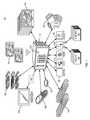
- FIG. 1is a block diagram of a system 90 which includes a programmable multimedia controller 100 interconnected to a number of devices.
- programmable multimedia controllershould be interpreted broadly as a device which includes a general purpose computer and is capable of controlling, switching data among, and/or otherwise interoperating with a variety of electrical and electronic devices, such as audio, video, telephony, data, security, motor-operated, relay-operated, heating, ventilation, and air conditioning (HVAC), energy management and/or other types of devices.
- HVACheating, ventilation, and air conditioning
- a line of programmable multimedia controllersare available from Savant Systems, LLC of Osterville, Mass.
- Programmable multimedia controller 100may be coupled to or interfaced with a variety of A/V devices, including audio source devices 110 , such as compact disk (CD) players, digital video disc (DVD) players, microphones, digital video recorders (DVRs), cable boxes, audio/video receivers, personal media players, and other devices that source audio signals.
- Audio source devices 110such as compact disk (CD) players, digital video disc (DVD) players, microphones, digital video recorders (DVRs), cable boxes, audio/video receivers, personal media players, and other devices that source audio signals.
- Programmable multimedia controller 100may also be coupled to or interfaced with a variety of video source devices 120 , such as DVD players, DVRs, personal media players and other devices that source video signals.
- Programmable multimedia controller 100may be coupled to or interfaced with a variety of audio output devices 130 , such as speakers, devices that incorporate speakers, and other devices that output audio, as well as a variety of video output devices 140 , such as televisions, monitors, and other devices that output video.
- programmable multimedia controller 100may be coupled to or interface with, control, and otherwise interoperate with a variety of other types of devices, either directly, or through one or more intermediate controllers.
- programmable multimedia controller 100may be coupled to a closed-circuit television (CCTV) control system 170 that manages a system of cameras positioned about a home or other structure, HVAC control and/or energy management system 175 that manages HVAC devices to regulate environmental functions and/or energy management devices in the home or other structure, and/or a security system 180 that manages a plurality of individual security sensors in the home or other structure.
- CCTV control system 170 , HVAC control system and/or energy management system 175 , and security system 180may manage the devices under their respective immediate control.
- programmable multimedia controller 100may be coupled to or interface with, control, and otherwise interoperate with, one or more electronic lighting controllers 190 .
- Electronic lighting controllers 190may be coupled to, for example, via wired or wireless links, a plurality of relays 192 and/or dimmer units 193 distributed throughout the home or other structure, and wired inline with the electrical feed to individual light fixtures located therein.
- electronic lighting controllers 190may selectively trigger relays 192 and/or adjust dimmer units 193 wired inline to particular light fixtures (not shown), to create a desired level of illumination or darkness in different rooms of the home or other structure.
- programmable multimedia controller 100may be coupled to or interfaced with, control, and otherwise interoperate with, one or more motor operated device controllers 195 , for example, one or more automatic window shade controllers, or other types of controllers.
- motor-operated device controllers 195may selectively trigger motor-operated devices (not shown) in various rooms of the home or other structure, to achieve desired effects.
- Programmable multimedia controller 100may receive user-input via one or more control units 150 , for example, wall-mounted control units, table-top control units, handheld portable control units, and the like, that include a display screen.
- Control units 150may include a touch screen interface, a mouse and pointer interface, or other type of interface.
- Control units 150may be special-purpose units, dedicated to operating with programmable multimedia controller 100 , or general-purpose devices, for example, laptop computers, desktop computers, and the like, configured with software to implement a user interface.
- control units 150may be coupled to programmable multimedia controller 100 via an intermediate device 153 , such a computer, via a wired or wireless connections or networks. In other cases, control units 150 may communicate directly to programmable multimedia controller 100 .
- Programmable multimedia controller 100may also receive user-input via one or more handheld button-centric remote control units and/or wall mounted button-centric control units 155 , or from one or more handheld remote control units including an annular touch sensor 157 .
- Remote control units including annular touch sensor 157may be adapted to manipulate, and make control selections using, an on-screen display (OSD) system. Further details regarding remote control units, including an annular touch sensor, and an OSD may be found in copending applications by Madonna et al., U.S. patent application Ser. No. 11/520,328, filed Sep. 13, 2006 and titled “Remote Control Unit for a Programmable Multimedia Controller,” U.S. patent application Ser. No. 11/687,511, filed Mar.
- Programmable multimedia controller 100may also receive user-input via one or more mobile devices 160 .
- mobile devicerefers to electronic devices that are adapted to be transported on one's person, including multimedia smartphones, such as the iPhone® multimedia phone available from Apple Inc. and the Blackberry® device available from Research In Motion Limited, multi-purpose tablet computing devices, such as the iPad® tablet available from Apple Inc., portable media players with enhanced capabilities, such as the iPod® touch available from Apple Inc., personal digital assistants (PDAs), electronic book readers, and the like.
- Such mobile devicesmay communicate directly with programmable multimedia controller 100 , or indirectly through various wireless, cellular, and/or wired networks (not shown).
- programmable multimedia controller 100may receive user-input via a touch screen or other interface integrated into programmable controller multimedia 100 itself, for example, a touch screen or other interface arranged as a front panel 165 of programmable multimedia controller 100 . Still further, programmable multimedia controller 100 may receive user-input via a touch screen integrated into a video output device 140 , such as a television.
- programmable multimedia controller 100may switch data among, issue control commands to, and/or otherwise interoperate with, audio source devices 110 , video source devices 120 , audio output devices 130 , and/or video output devices 140 .
- programmable multimedia controller 100may issue control commands to, and otherwise interoperate with, CCTV control system 170 , HVAC control and/or energy management system 175 , security system 180 , electronic lighting controllers 190 , as well as motor operated device controllers 195 .
- FIG. 2is a schematic block diagram of a high-level hardware architecture 200 for programmable multimedia controller 100 .
- the various components shownmay be arranged on a “motherboard” of programmable multimedia controller 100 , or on a plurality of circuit cards interconnected by a backplane (not shown).
- a microcontroller 210manages the general operation of programmable multimedia controller 100 .
- Microcontroller 210in some configurations, is coupled to an audio switch 215 and a video switch 220 via a bus 218 .
- Audio switch 215 and video switch 220are preferably crosspoint switches capable of switching a number of connections simultaneously. However, many other types of switches capable of switching digital signals may be employed, for example Time Division Multiplexing (TDM) switches or other devices.
- TDMTime Division Multiplexing
- a mid plane 235interconnects audio and video switches 215 , 220 to a variety of input and output modules, for example, one or more Video Input/Output Modules 300 , one or more Audio Input/Output Modules 290 , and/or one or more other modules 295 .
- Mid plane 235is further coupled to an Ethernet switch 230 that permits switching of 10BaseT, 100BaseT, Gigabyte Ethernet and/or other types of data signals.
- Ethernet switch 230interconnects Ethernet ports 232 and a processing subsystem 240 to microcontroller 210 .
- processing subsystem 240includes one or more “general-purpose computers” 245 .
- a general-purpose computer 245refers to a device that is configured to execute a set of instructions, and depending upon the particular instructions executed, may perform a variety of different functions or tasks.
- a general-purpose computer 245executes a general-purpose operating system, such as the Windows® operating system, available from Microsoft Corporation, the Linux® operating system, available from a variety of vendors, the OSX® operating system, available from Apple Inc., or another operating system.
- a general-purpose computer 245may have any of a variety of form factors.
- a general-purpose computer 245may be a Central Processing Unit (CPU) card, a Single Board Computer (SBC), a PC/104 processing module, a conventional ATX form factor motherboard and CPU, an “off-the-shelf” small form factor general-purpose personal computer including a case, power supply, and other accessories, an “off-the-shelf” large form factor general-purpose personal computer including a case, power supply, and other accessories, and/or a rack-mount general-purpose personal computer including a case, power supply, and other accessories.
- CPUCentral Processing Unit
- SBCSingle Board Computer
- General-purpose computer 245may include a storage device, for example a hard drive, a compact disc read-only memory (CDROM) drive, a Flash memory, or other type of storage device, and/or may be interconnected to a storage device provided elsewhere in the processing subsystem 240 .
- a storage devicefor example a hard drive, a compact disc read-only memory (CDROM) drive, a Flash memory, or other type of storage device, and/or may be interconnected to a storage device provided elsewhere in the processing subsystem 240 .
- Processing subsystem 240preferably has one or more graphics outputs 241 , 242 such as analog Video Graphics Array (VGA) connectors, Digital Visual Interface (DVI) connectors, Apple Display Connector (ADC) connectors, or other type of connectors, for supplying graphics.
- graphics outputs 241 , 242may, for example, be supplied directly from the one or more general-purpose computers 245 of the processing subsystem 240 .
- graphicsshould be interpreted broadly to encompass a wide variety of computer graphics, text, full-motion video, still images, or other types of visual data, represented in any of a variety of different color spaces, for example RGB, YCrCb, and the like, at any of a variety of different color depths, for example 8-bit color, 16-bit color, 24-bit color, 32-bit color, and the like.
- Graphics from processing subsystem 240are passed to video switch 220 , in some configurations, and then switched to other parts of programmable multimedia controller 100 , for example to Video Input/Output Modules 300 . Alternately, graphics from processing subsystem 240 , in some arrangements, may pass directly to a module, such as Video Input/Output Modules 300 .
- USBUniversal Serial Bus
- a memory card interface 225is also connected to USB hub 243 .
- the interfacemay accept one or more well-known memory card formats, for example CompactFlashTM cards, Memory StickTM cards, Secure DigitalTM (SD) cards, or other formats.
- a USB switch 244is employed to switch USB links to processing subsystem 240 .
- a number of IEEE 1394 (FireWireTM) ports 246are interconnected to an IEEE 1394 hub 247 and to an IEEE 1394 switch 248 , for switching to the processing subsystem 240 .
- Microcontroller 210is further connected to a Serial Peripheral Interface (SPI) and Inter-Integrated Circuit (I 2 C) distribution circuit 250 , which provides a serial communication interface to relatively low data transfer rate devices.
- SPI/I 2 C controller 250is connected to mid plane 235 and thereby provides control commands from microcontroller 210 to modules 290 , 295 , 300 and other devices of the programmable multimedia controller 100 . Further, connections from the SPI/I 2 C controller 250 are provided to devices such as a fan controller 251 , a temperature sensor 252 , and a power manager circuit 253 , which collectively manage the thermal characteristics of programmable multimedia controller 100 and prevent overheating.
- Microcontroller 210is also connected to an Infra-Red (IR) interface 260 , an RS232 interface 265 , and a RF interface 267 , each of which permits further interconnection with external devices. Also, a device control interface 275 is provided to communicate with lighting, home automation, and motor and/or relay operated devices. It is expressly contemplated that various other interfaces, including WI-FI, BluetoothTM, Zig-BeeTM and/or other wired and wireless interfaces, may be employed by programmable multimedia controller 100 .
- an expansion port 280is provided for linking several programmable multimedia controllers 100 together, to form an expanded system, while a front panel display 285 , for example a touch screen Liquid Crystal Display (LCD) display, is provided to display status, configuration, and/or other information to a user, as well as to accept user input.
- LCDLiquid Crystal Display
- FIG. 3is a functional block diagram of certain hardware components and software processes which may be involved in creating or modifying graphical schedules as described in detail below.
- a multi-touch device 302which represents one type of user interface device that may be used in connection with the present invention, may be implemented with an iPod® Touch, iPhone® and iPad® from Apple Inc. (not shown).
- An on-screen display (OSD) 304which represents an alternative type of user interface device that may be used in connection with the present invention, is described in the copending applications incorporated by referenced above.
- Yet another alternative type of user interface devicewould be a computer with a video monitor, keyboard and mouse (not shown).
- a network process 306provides the basic functionality to support both wired and wireless network communication with multi-touch device 302 and OSD 304 .
- Information (user input) received from multi-touch device 302 and OSD 304is passed by network process 306 to a data integration service 308 .
- data integration service 308interprets commands received from multi-touch device 302 and OSD 304 , stores data points and provides appropriate feedback (e.g., changes in screen appearance, sounds, etc.) to multi-touch device 302 and OSD 304 .
- Data integration service 308provides a generic engine for data manipulation and presentation with user interfaces. Among other functions, data integration service 308 may store data in, as well as retrieve data from, a database 310 or other suitable store. With respect to graphical schedules, data integration service 308 uses database 310 to store schedule points as described below.
- a scheduler process 312communicates with data integration service 308 and is capable of recognizing schedule points previously stored by that service. Once the current day (or date) or time, or both, match a stored schedule point, scheduler process 312 issues appropriate messages or commands to a service controller 314 . Depending upon the action(s) to be taken, in accordance with a schedule previously created by a user, service controller 314 issues appropriate messages or commands to one or more devices such as HVAC controller 316 , lighting controller 318 , audio/video (AV) receiver 320 , DVD controller 322 , shade controller 324 and personal media player 326 which are controlled by a programmable multimedia controller 100 ( FIG. 1 ).
- AVaudio/video
- FIG. 4depicts a main screen 400 of a graphical user interface which enables a user to create and modify graphical schedules for devices controlled by programmable multimedia controller 100 of FIG. 1 .
- User control buttons 402enable a user to select a major category such as All, Video, Music, Env(ironmental), Settings and My Favorites. As indicated by a boldface border, a user has selected the Settings category by pressing button 404 .
- buttons 406appear and these include Category Settings, Surround Sound, Video, Favorites Editor and HVAC Schedules. Again, as indicated by a boldface border, a user has selected HVAC Scheduling by pressing button 408 .
- a workspace 410is provided in which a graphical schedule may be displayed, as described below.
- a control button 412By pressing a control button 412 , a user may initiate the creation of a new graphical schedule for HVAC in workspace 410 .
- a control button 414a user may recall from persistent data storage (not shown) one or more existing or “working” graphical schedule(s) for HVAC.
- popover menu 416allows a user to edit or copy the working graphical schedule, to display a summary, to assign the working schedule to zones (e.g., particular rooms or portions of a home) or to assign the working schedule to all zones.
- zonese.g., particular rooms or portions of a home
- assign the working schedule to all zonese.g., particular rooms or portions of a home
- a userwishes to edit an HVAC working graphical schedule and presses the Edit Schedule box in popover 416 . This action will result in the HVAC working graphical schedule being retrieved from data storage and displayed in workspace 410 as shown in FIG. 5 .
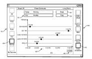
- HVAC working graphical schedule 500is displayed in workspace 410 .
- text boxes 502identify the name (Working) of graphical schedule 500 and the day of week (Monday) to which it applies.
- a popover menu(not shown) may appear to enable a user to change the day of week.
- a control button 504Done
- a control button 506Copy
- Copy optionsmay include copying a graphical schedule from the previous day, copy the currently displayed graphical schedule to the next day, or copying the currently displayed graphical schedule to all weekdays, all weekend days or all days.
- Graphical schedule 500shows a 24 hour time of day along a horizontal axis and temperature along a vertical axis. For any given time, there are two temperatures. The higher temperature (e.g., 75° between 12:00 a.m. and 6:00 a.m.) represents a maximum temperature that must be reached before the HVAC system cools the room. The lower temperature represents a minimum temperature (e.g., 65° between 12:00 a.m. and 6:00 a.m.) that must be reached before the HVAC system heats the room. Control buttons 508 ( ⁇ /+) enable a user to remove or add, respectively, schedule points to graphical schedule 500 .
- the higher temperaturee.g., 75° between 12:00 a.m. and 6:00 a.m.
- the lower temperaturerepresents a minimum temperature (e.g., 65° between 12:00 a.m. and 6:00 a.m.) that must be reached before the HVAC system heats the room.
- Control buttons 508( ⁇ /+) enable a user to remove or add, respectively
- graphical schedule 500When graphical schedule 500 is displayed on a touch-sensitive device, a user may easily and rapidly modify the temperatures or time boundaries with swipes or similar gestures. Alternatively, modifications may also be made through a user's interactions with an on-screen display, a keyboard, mouse or other user input device.
- FIG. 6depicts a main screen 400 of a graphical user interface which enables a user to create and modify presets which are associated with devices controlled by programmable multimedia controller 100 of FIG. 1 .
- User control buttons 402enable a user to select a major category such as All, Video, Music, Env(ironmental), Settings and My Favorites. As indicated by a boldface border, a user has selected the Settings category by pressing button 404 .
- buttons 602which correspond to various devices controlled by programmable multimedia controller 100 .
- control buttons 602correspond, respectively, to Office Cable, Living Room Blu-ray, Living Room Lights and Security Cameras.
- Schedule ProfilesAs indicated by a boldface border, a user has selected Schedule Profiles by pressing button 604 .
- Working 606the profile of a user
- Summer 608the profile of a user
- Evening Lighting 610the last of a user wishes to view and possibly modify presets associated with the last. By selecting Evening Lighting 610 , as indicated by the boldface border, this action will result in the presets associated with that profile being displayed as shown in FIG. 7 .
- FIG. 7a different set of control buttons 702 are displayed. As indicated by a boldface border, a user has pressed control button 704 (Presets) in order to view and possibly modify a configuration of an Evening Lights On preset 706 .
- Evening Lights On preset 706operates to turn on certain lights, set the position of certain shades, and possibly perform other actions at a predetermined time in the evening.
- Evening Lights On preset 706operates to create a user-selected environmental state for a predetermined physical space.
- preset configuration 708Shown in Evening Lights On preset configuration 708 are the name of the preset, the zones (i.e., physical space(s)) and service categories which are impacted by the preset's actions, the particular devices (i.e., individual lights and shades) that are impacted by the preset's actions.
- each other item shown in preset configuration 708has a popover menu (not shown) which enables a user to modify the configuration.
- a usermay press a Save button 710 in order to save the changes. If a user wished to discard the changes, he or she would press a Cancel button 712 .
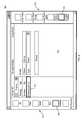
- a graphical schedule 800which includes several presets is displayed in workspace 410 and is available for editing.
- text boxes 802identify the name (Working) of graphical schedule 800 and the day of week (Monday) to which it applies.
- a popover menu(not shown) may appear to enable a user to change the day of week.
- a control button 804Done
- a control button 806Copy
- a popover menu(not shown) of copy options will appear.
- Graphical schedule 800shows a 24 hour time of day along a horizontal axis and a total of five presets along a vertical axis. For example, a first preset named Dish Washer is scheduled to run at 2:00 a.m. A second preset named Bed Time is scheduled to run at 11:00 p.m.
- Control buttons 808( ⁇ /+) enable a user to remove or add, respectively, presets to graphical schedule 800 .
- graphical schedule 800is displayed on a touch-sensitive device, a user may easily and rapidly modify the scheduled times at which presets run with swipes or similar gestures. Alternatively, modifications may also be made through a user's interactions with an on-screen display, a keyboard, mouse or other user input device.
- a usermay assign a preset to a desired button in a user interface. In this fashion, a user may run a desired preset on demand by pressing the assigned button. Details regarding button assignment are provided in U.S. patent application Ser. No. 11/687,458 incorporated by reference above.
Landscapes
- Engineering & Computer Science (AREA)
- General Engineering & Computer Science (AREA)
- Theoretical Computer Science (AREA)
- Human Computer Interaction (AREA)
- Physics & Mathematics (AREA)
- General Physics & Mathematics (AREA)
- User Interface Of Digital Computer (AREA)
Abstract
Description
Claims (21)
Priority Applications (15)
| Application Number | Priority Date | Filing Date | Title |
|---|---|---|---|
| US13/081,183US8914724B2 (en) | 2011-04-06 | 2011-04-06 | Method and apparatus for creating and modifying graphical schedules |
| US13/097,189US20120260206A1 (en) | 2011-04-06 | 2011-04-29 | Method and apparatus for creating and modifying graphical schedules in conjunction with historical data |
| RU2013146662ARU2611994C2 (en) | 2011-04-06 | 2012-04-05 | Method and apparatus for creating and modifying graphical schedules |
| EP12720305.7AEP2695332B1 (en) | 2011-04-06 | 2012-04-05 | Method and apparatus for creating and modifying graphical schedules |
| MX2013011455AMX340371B (en) | 2011-04-06 | 2012-04-05 | Method and apparatus for creating and modifying graphical schedules. |
| NZ616350ANZ616350B2 (en) | 2011-04-06 | 2012-04-05 | Method and apparatus for creating and modifying graphical schedules |
| CA2832335ACA2832335C (en) | 2011-04-06 | 2012-04-05 | Method and apparatus for creating and modifying graphical schedules |
| BR112013025793-8ABR112013025793B1 (en) | 2011-04-06 | 2012-04-05 | METHOD AND APPARATUS FOR CREATING AND MODIFYING GRAPHIC PROGRAMS |
| KR1020137029114AKR101932786B1 (en) | 2011-04-06 | 2012-04-05 | Method and apparatus for creating and modifying graphical schedules |
| PCT/US2012/000191WO2012138401A1 (en) | 2011-04-06 | 2012-04-05 | Method and apparatus for creating and modifying graphical schedules |
| CN201280027628.XACN103583018B (en) | 2011-04-06 | 2012-04-05 | Method and apparatus for creating and modifying graphical schedule |
| AU2012240571AAU2012240571B2 (en) | 2011-04-06 | 2012-04-05 | Method and apparatus for creating and modifying graphical schedules |
| JP2014503651AJP6050312B2 (en) | 2011-04-06 | 2012-04-05 | Method and apparatus for creating and modifying a graphical schedule |
| ES12720305TES2714222T3 (en) | 2011-04-06 | 2012-04-05 | Procedure and apparatus for creating and modifying graphic programming |
| IL228698AIL228698A (en) | 2011-04-06 | 2013-10-02 | Method and apparatus for creating and modifying graphical schedules |
Applications Claiming Priority (1)
| Application Number | Priority Date | Filing Date | Title |
|---|---|---|---|
| US13/081,183US8914724B2 (en) | 2011-04-06 | 2011-04-06 | Method and apparatus for creating and modifying graphical schedules |
Related Child Applications (1)
| Application Number | Title | Priority Date | Filing Date |
|---|---|---|---|
| US13/097,189Continuation-In-PartUS20120260206A1 (en) | 2011-04-06 | 2011-04-29 | Method and apparatus for creating and modifying graphical schedules in conjunction with historical data |
Publications (2)
| Publication Number | Publication Date |
|---|---|
| US20120260166A1 US20120260166A1 (en) | 2012-10-11 |
| US8914724B2true US8914724B2 (en) | 2014-12-16 |
Family
ID=46967078
Family Applications (1)
| Application Number | Title | Priority Date | Filing Date |
|---|---|---|---|
| US13/081,183Active2033-02-13US8914724B2 (en) | 2011-04-06 | 2011-04-06 | Method and apparatus for creating and modifying graphical schedules |
Country Status (1)
| Country | Link |
|---|---|
| US (1) | US8914724B2 (en) |
Cited By (4)
| Publication number | Priority date | Publication date | Assignee | Title |
|---|---|---|---|---|
| US20160070244A1 (en)* | 2014-09-09 | 2016-03-10 | Savant Systems, Llc | User-defined scenes for home automation |
| US20170045864A1 (en)* | 2010-11-19 | 2017-02-16 | Google Inc. | Systems and Methods for Energy-Efficient Control of an Energy-Consuming System |
| US20180299162A1 (en)* | 2017-04-14 | 2018-10-18 | Johnson Controls Technology Company | Multi-function thermostat with event schedule controls |
| US12271960B2 (en) | 2019-09-11 | 2025-04-08 | Savant Systems, Inc. | Energy management system and methods |
Families Citing this family (5)
| Publication number | Priority date | Publication date | Assignee | Title |
|---|---|---|---|---|
| US20130178985A1 (en)* | 2012-01-10 | 2013-07-11 | Ecobee Inc. | Hvac controller with time of use scheduler |
| US9058583B2 (en) | 2012-09-06 | 2015-06-16 | Sap Se | Systems and methods for mobile access to item information |
| US20140068445A1 (en)* | 2012-09-06 | 2014-03-06 | Sap Ag | Systems and Methods for Mobile Access to Enterprise Work Area Information |
| JP2015219751A (en) | 2014-05-19 | 2015-12-07 | 株式会社デンソーウェーブ | Air conditioner operation device |
| US10747290B1 (en)* | 2018-03-30 | 2020-08-18 | Shopkick, Inc. | Varying application strategy based on device state |
Citations (35)
| Publication number | Priority date | Publication date | Assignee | Title |
|---|---|---|---|---|
| US5566084A (en)* | 1993-03-02 | 1996-10-15 | Cmar; Gregory | Process for identifying patterns of electric energy effects of proposed changes, and implementing such changes in the facility to conserve energy |
| US6067482A (en)* | 1999-01-08 | 2000-05-23 | Hussmann Corporation | Load shifting control system for commercial refrigeration |
| US6160359A (en)* | 1998-01-30 | 2000-12-12 | Hewlett-Packard Company | Apparatus for communicating with a remote computer to control an assigned lighting load |
| US6366889B1 (en)* | 1998-05-18 | 2002-04-02 | Joseph A. Zaloom | Optimizing operational efficiency and reducing costs of major energy system at large facilities |
| US20030016247A1 (en)* | 2001-07-18 | 2003-01-23 | International Business Machines Corporation | Method and system for software applications using a tiled user interface |
| US20030110926A1 (en)* | 1996-07-10 | 2003-06-19 | Sitrick David H. | Electronic image visualization system and management and communication methodologies |
| US6756998B1 (en)* | 2000-10-19 | 2004-06-29 | Destiny Networks, Inc. | User interface and method for home automation system |
| US20040138981A1 (en)* | 2002-03-28 | 2004-07-15 | Ehlers Gregory A | System and method of controlling delivery and/or usage of a commodity |
| US20050149233A1 (en)* | 2004-01-07 | 2005-07-07 | Metz Stephen V. | Controller interface with dynamic schedule display |
| US7047092B2 (en)* | 2003-04-08 | 2006-05-16 | Coraccess Systems | Home automation contextual user interface |
| US20060288842A1 (en)* | 1996-07-10 | 2006-12-28 | Sitrick David H | System and methodology for image and overlaid annotation display, management and communicaiton |
| US7167777B2 (en)* | 2003-11-04 | 2007-01-23 | Powerweb Technologies | Wireless internet lighting control system |
| US7181317B2 (en)* | 2003-12-02 | 2007-02-20 | Honeywell International Inc. | Controller interface with interview programming |
| US20070092229A1 (en)* | 2000-11-29 | 2007-04-26 | Masako Ninomiya | Optical disc, recording apparatus, reproducing apparatus, program, computer-readable recording medium, recording method and reproducing method |
| US20070198099A9 (en)* | 2000-10-26 | 2007-08-23 | Shah Dipak J | Graphical user interface system for a thermal comfort controller |
| US20080019610A1 (en)* | 2004-03-17 | 2008-01-24 | Kenji Matsuzaka | Image processing device and image processing method |
| US20080079604A1 (en)* | 2006-09-13 | 2008-04-03 | Madonna Robert P | Remote control unit for a programmable multimedia controller |
| US20080127063A1 (en)* | 2006-09-13 | 2008-05-29 | Silva Michael C | Programming environment and metadata management for programmable multimedia controller |
| US20080158148A1 (en)* | 2006-09-13 | 2008-07-03 | Madonna Robert P | Programmable on screen display and remote control |
| US20080270937A1 (en)* | 2005-03-01 | 2008-10-30 | Olivier Poulet | Control Interface for a Home Automation System and Method for Operating Same |
| US20080306632A1 (en)* | 2006-12-22 | 2008-12-11 | Daikin Industries, Ltd. | Air Conditioning Control Device |
| US7603200B2 (en)* | 2004-06-15 | 2009-10-13 | Abb Patent Gmbh | Method and system for assessing the state of at least one axial joint |
| JP2009275928A (en) | 2008-05-12 | 2009-11-26 | Mitsubishi Electric Corp | Bathroom ventilating-drying-heating system |
| US20100023865A1 (en)* | 2005-03-16 | 2010-01-28 | Jim Fulker | Cross-Client Sensor User Interface in an Integrated Security Network |
| US20100162160A1 (en)* | 2008-12-22 | 2010-06-24 | Verizon Data Services Llc | Stage interaction for mobile device |
| US20100312366A1 (en)* | 2009-06-03 | 2010-12-09 | Savant Systems Llc | Virtual room-based light fixture and device control |
| US20110004825A1 (en)* | 2008-08-22 | 2011-01-06 | Lennox Industries, Incorporated | Display apparatus and method having multiple day programming capability for an environmental control system |
| US7890195B2 (en)* | 2003-12-01 | 2011-02-15 | Honeywell International Inc. | Controller interface with multiple day programming |
| US20110083094A1 (en)* | 2009-09-29 | 2011-04-07 | Honeywell International Inc. | Systems and methods for displaying hvac information |
| US20110184565A1 (en)* | 2010-01-22 | 2011-07-28 | Honeywell International Inc. | Hvac control with utility time of day pricing support |
| US20110219339A1 (en)* | 2010-03-03 | 2011-09-08 | Gilray Densham | System and Method for Visualizing Virtual Objects on a Mobile Device |
| US20110320044A1 (en)* | 2010-06-29 | 2011-12-29 | Cisco Technology, Inc. | System and method for providing environmental controls for a meeting session in a network environment |
| US20120081750A1 (en)* | 2006-08-14 | 2012-04-05 | Canon Kabushiki Kaisha | Image processing apparatus, control method of image processing apparatus, program and storage medium |
| US20120185801A1 (en)* | 2011-01-18 | 2012-07-19 | Savant Systems, Llc | Remote control interface providing head-up operation and visual feedback when interacting with an on screen display |
| US20120260206A1 (en)* | 2011-04-06 | 2012-10-11 | Cipollo Nicholas J | Method and apparatus for creating and modifying graphical schedules in conjunction with historical data |
- 2011
- 2011-04-06USUS13/081,183patent/US8914724B2/enactiveActive
Patent Citations (40)
| Publication number | Priority date | Publication date | Assignee | Title |
|---|---|---|---|---|
| US5566084A (en)* | 1993-03-02 | 1996-10-15 | Cmar; Gregory | Process for identifying patterns of electric energy effects of proposed changes, and implementing such changes in the facility to conserve energy |
| US20060288842A1 (en)* | 1996-07-10 | 2006-12-28 | Sitrick David H | System and methodology for image and overlaid annotation display, management and communicaiton |
| US20030110926A1 (en)* | 1996-07-10 | 2003-06-19 | Sitrick David H. | Electronic image visualization system and management and communication methodologies |
| US6160359A (en)* | 1998-01-30 | 2000-12-12 | Hewlett-Packard Company | Apparatus for communicating with a remote computer to control an assigned lighting load |
| US6366889B1 (en)* | 1998-05-18 | 2002-04-02 | Joseph A. Zaloom | Optimizing operational efficiency and reducing costs of major energy system at large facilities |
| US6067482A (en)* | 1999-01-08 | 2000-05-23 | Hussmann Corporation | Load shifting control system for commercial refrigeration |
| US6756998B1 (en)* | 2000-10-19 | 2004-06-29 | Destiny Networks, Inc. | User interface and method for home automation system |
| US20070198099A9 (en)* | 2000-10-26 | 2007-08-23 | Shah Dipak J | Graphical user interface system for a thermal comfort controller |
| US7360717B2 (en)* | 2000-10-26 | 2008-04-22 | Honeywell International Inc. | Graphical user interface system for a thermal comfort controller |
| US20070092229A1 (en)* | 2000-11-29 | 2007-04-26 | Masako Ninomiya | Optical disc, recording apparatus, reproducing apparatus, program, computer-readable recording medium, recording method and reproducing method |
| US20030016247A1 (en)* | 2001-07-18 | 2003-01-23 | International Business Machines Corporation | Method and system for software applications using a tiled user interface |
| US20040138981A1 (en)* | 2002-03-28 | 2004-07-15 | Ehlers Gregory A | System and method of controlling delivery and/or usage of a commodity |
| US7047092B2 (en)* | 2003-04-08 | 2006-05-16 | Coraccess Systems | Home automation contextual user interface |
| US7167777B2 (en)* | 2003-11-04 | 2007-01-23 | Powerweb Technologies | Wireless internet lighting control system |
| US7890195B2 (en)* | 2003-12-01 | 2011-02-15 | Honeywell International Inc. | Controller interface with multiple day programming |
| US7181317B2 (en)* | 2003-12-02 | 2007-02-20 | Honeywell International Inc. | Controller interface with interview programming |
| US20050149233A1 (en)* | 2004-01-07 | 2005-07-07 | Metz Stephen V. | Controller interface with dynamic schedule display |
| US7142948B2 (en)* | 2004-01-07 | 2006-11-28 | Honeywell International Inc. | Controller interface with dynamic schedule display |
| US20080019610A1 (en)* | 2004-03-17 | 2008-01-24 | Kenji Matsuzaka | Image processing device and image processing method |
| US7603200B2 (en)* | 2004-06-15 | 2009-10-13 | Abb Patent Gmbh | Method and system for assessing the state of at least one axial joint |
| US20080270937A1 (en)* | 2005-03-01 | 2008-10-30 | Olivier Poulet | Control Interface for a Home Automation System and Method for Operating Same |
| US20100023865A1 (en)* | 2005-03-16 | 2010-01-28 | Jim Fulker | Cross-Client Sensor User Interface in an Integrated Security Network |
| US20120081750A1 (en)* | 2006-08-14 | 2012-04-05 | Canon Kabushiki Kaisha | Image processing apparatus, control method of image processing apparatus, program and storage medium |
| US20080158148A1 (en)* | 2006-09-13 | 2008-07-03 | Madonna Robert P | Programmable on screen display and remote control |
| US20080079604A1 (en)* | 2006-09-13 | 2008-04-03 | Madonna Robert P | Remote control unit for a programmable multimedia controller |
| US20080127063A1 (en)* | 2006-09-13 | 2008-05-29 | Silva Michael C | Programming environment and metadata management for programmable multimedia controller |
| US20110167348A1 (en)* | 2006-09-13 | 2011-07-07 | Savant Systems, Llc | Programming environment for configuring a system of audio/video components |
| US20080306632A1 (en)* | 2006-12-22 | 2008-12-11 | Daikin Industries, Ltd. | Air Conditioning Control Device |
| JP2009275928A (en) | 2008-05-12 | 2009-11-26 | Mitsubishi Electric Corp | Bathroom ventilating-drying-heating system |
| US20110004825A1 (en)* | 2008-08-22 | 2011-01-06 | Lennox Industries, Incorporated | Display apparatus and method having multiple day programming capability for an environmental control system |
| US20100162160A1 (en)* | 2008-12-22 | 2010-06-24 | Verizon Data Services Llc | Stage interaction for mobile device |
| US20100312366A1 (en)* | 2009-06-03 | 2010-12-09 | Savant Systems Llc | Virtual room-based light fixture and device control |
| US20120284672A1 (en)* | 2009-06-03 | 2012-11-08 | Savant Systems, Llc | Virtual room-based light fixture and device control |
| US8296669B2 (en)* | 2009-06-03 | 2012-10-23 | Savant Systems, Llc | Virtual room-based light fixture and device control |
| US20110083094A1 (en)* | 2009-09-29 | 2011-04-07 | Honeywell International Inc. | Systems and methods for displaying hvac information |
| US20110184565A1 (en)* | 2010-01-22 | 2011-07-28 | Honeywell International Inc. | Hvac control with utility time of day pricing support |
| US20110219339A1 (en)* | 2010-03-03 | 2011-09-08 | Gilray Densham | System and Method for Visualizing Virtual Objects on a Mobile Device |
| US20110320044A1 (en)* | 2010-06-29 | 2011-12-29 | Cisco Technology, Inc. | System and method for providing environmental controls for a meeting session in a network environment |
| US20120185801A1 (en)* | 2011-01-18 | 2012-07-19 | Savant Systems, Llc | Remote control interface providing head-up operation and visual feedback when interacting with an on screen display |
| US20120260206A1 (en)* | 2011-04-06 | 2012-10-11 | Cipollo Nicholas J | Method and apparatus for creating and modifying graphical schedules in conjunction with historical data |
Non-Patent Citations (3)
| Title |
|---|
| "Notification of Transmittal of the International Search Report and the Written Opinion of the International Searching Authority, or the Declaration," International Filing Date: Apr. 5, 2012, International Application No. PCT/US2012/000191, Applicant: SAVANT SYSTEMS, LLC., Date of Mailing: Aug. 28, 2012, pp. 1-13. |
| Meliones, A., et al., "A Context Aware Connected Home Platform for Pervasive Applications," 2008 Second IEEE International Conference on Self-Adaptive and Self-Organizing Systems Workshops, IEEE Computer Society, Oct. 20, 2008, pp. 120-125. |
| U.S. Appl. No. 11/687,511 entitled System and Method for Mixing Graphics with video images or Other Content filed on Mar. 16, 2007 by Robert P. Madonna, 31 pages. |
Cited By (7)
| Publication number | Priority date | Publication date | Assignee | Title |
|---|---|---|---|---|
| US20170045864A1 (en)* | 2010-11-19 | 2017-02-16 | Google Inc. | Systems and Methods for Energy-Efficient Control of an Energy-Consuming System |
| US10175668B2 (en)* | 2010-11-19 | 2019-01-08 | Google Llc | Systems and methods for energy-efficient control of an energy-consuming system |
| US20160070244A1 (en)* | 2014-09-09 | 2016-03-10 | Savant Systems, Llc | User-defined scenes for home automation |
| US10042336B2 (en)* | 2014-09-09 | 2018-08-07 | Savant Systems, Llc | User-defined scenes for home automation |
| US20180299162A1 (en)* | 2017-04-14 | 2018-10-18 | Johnson Controls Technology Company | Multi-function thermostat with event schedule controls |
| US10648690B2 (en)* | 2017-04-14 | 2020-05-12 | Johnson Controls Technology Company | Multi-function thermostat with event schedule controls |
| US12271960B2 (en) | 2019-09-11 | 2025-04-08 | Savant Systems, Inc. | Energy management system and methods |
Also Published As
| Publication number | Publication date |
|---|---|
| US20120260166A1 (en) | 2012-10-11 |
Similar Documents
| Publication | Publication Date | Title |
|---|---|---|
| AU2012240571B2 (en) | Method and apparatus for creating and modifying graphical schedules | |
| US8914724B2 (en) | Method and apparatus for creating and modifying graphical schedules | |
| EP2619993B1 (en) | Programmable multimedia controller with flexible user access and shared device configurations | |
| US8296669B2 (en) | Virtual room-based light fixture and device control | |
| NZ616350B2 (en) | Method and apparatus for creating and modifying graphical schedules |
Legal Events
| Date | Code | Title | Description |
|---|---|---|---|
| AS | Assignment | Owner name:SAVANT SYSTEMS, LLC, MASSACHUSETTS Free format text:ASSIGNMENT OF ASSIGNORS INTEREST;ASSIGNORS:CIPOLLO, NICHOLAS J.;SILVA, MICHAEL C.;LOCASCIO, TIMOTHY R.;REEL/FRAME:026454/0991 Effective date:20110615 | |
| STCF | Information on status: patent grant | Free format text:PATENTED CASE | |
| CC | Certificate of correction | ||
| MAFP | Maintenance fee payment | Free format text:PAYMENT OF MAINTENANCE FEE, 4TH YR, SMALL ENTITY (ORIGINAL EVENT CODE: M2551) Year of fee payment:4 | |
| FEPP | Fee payment procedure | Free format text:ENTITY STATUS SET TO UNDISCOUNTED (ORIGINAL EVENT CODE: BIG.); ENTITY STATUS OF PATENT OWNER: LARGE ENTITY | |
| AS | Assignment | Owner name:SAVANT SYSTEMS, INC., MASSACHUSETTS Free format text:MERGER AND CHANGE OF NAME;ASSIGNORS:SAVANT SYSTEMS, LLC;SAVANT SYSTEMS, INC.;REEL/FRAME:052909/0298 Effective date:20200524 | |
| AS | Assignment | Owner name:PNC BANK, NATIONAL ASSOCIATION, PENNSYLVANIA Free format text:SECURITY INTEREST;ASSIGNORS:SAVANT SYSTEMS, INC.;CONSUMER LIGHTING (U.S.), LLC;REEL/FRAME:053095/0001 Effective date:20200630 | |
| AS | Assignment | Owner name:RACEPOINT ENERGY, LLC, OHIO Free format text:RELEASE BY SECURED PARTY;ASSIGNOR:PNC BANK, NATIONAL ASSOCIATION;REEL/FRAME:059910/0312 Effective date:20220331 Owner name:SAVANT TECHNOLOGIES LLC, OHIO Free format text:RELEASE BY SECURED PARTY;ASSIGNOR:PNC BANK, NATIONAL ASSOCIATION;REEL/FRAME:059910/0312 Effective date:20220331 Owner name:SAVANT SYSTEMS, INC., MASSACHUSETTS Free format text:RELEASE BY SECURED PARTY;ASSIGNOR:PNC BANK, NATIONAL ASSOCIATION;REEL/FRAME:059910/0312 Effective date:20220331 | |
| MAFP | Maintenance fee payment | Free format text:PAYMENT OF MAINTENANCE FEE, 8TH YEAR, LARGE ENTITY (ORIGINAL EVENT CODE: M1552); ENTITY STATUS OF PATENT OWNER: LARGE ENTITY Year of fee payment:8 |