US8914245B2 - Ultrasound probe with accelerometer - Google Patents
Ultrasound probe with accelerometerDownload PDFInfo
- Publication number
- US8914245B2 US8914245B2US13/256,763US201013256763AUS8914245B2US 8914245 B2US8914245 B2US 8914245B2US 201013256763 AUS201013256763 AUS 201013256763AUS 8914245 B2US8914245 B2US 8914245B2
- Authority
- US
- United States
- Prior art keywords
- probe
- sound waves
- subject
- transducer
- micro
- Prior art date
- Legal status (The legal status is an assumption and is not a legal conclusion. Google has not performed a legal analysis and makes no representation as to the accuracy of the status listed.)
- Active, expires
Links
- 239000000523sampleSubstances0.000titleclaimsabstractdescription151
- 238000002604ultrasonographyMethods0.000titledescription15
- 238000001514detection methodMethods0.000claimsdescription19
- 210000000056organAnatomy0.000claimsdescription12
- 239000013078crystalSubstances0.000claimsdescription7
- 238000012545processingMethods0.000claimsdescription6
- 239000000872bufferSubstances0.000claimsdescription3
- 238000012285ultrasound imagingMethods0.000claims1
- 238000000034methodMethods0.000description10
- 230000004044responseEffects0.000description6
- 238000006073displacement reactionMethods0.000description4
- 210000002307prostateAnatomy0.000description4
- 230000003187abdominal effectEffects0.000description3
- 230000001133accelerationEffects0.000description3
- 239000012530fluidSubstances0.000description3
- 238000011835investigationMethods0.000description2
- 210000003903pelvic floorAnatomy0.000description2
- 230000035939shockEffects0.000description2
- 210000003708urethraAnatomy0.000description2
- ZMHWQAHZKUPENF-UHFFFAOYSA-N1,2-dichloro-3-(4-chlorophenyl)benzeneChemical compoundC1=CC(Cl)=CC=C1C1=CC=CC(Cl)=C1ClZMHWQAHZKUPENF-UHFFFAOYSA-N0.000description1
- 238000013459approachMethods0.000description1
- 230000005484gravityEffects0.000description1
- 239000007788liquidSubstances0.000description1
- 238000005259measurementMethods0.000description1
- 230000007935neutral effectEffects0.000description1
- 210000000664rectumAnatomy0.000description1
- 210000001519tissueAnatomy0.000description1
- 230000000007visual effectEffects0.000description1
- 239000002699waste materialSubstances0.000description1
Images


Classifications
- A—HUMAN NECESSITIES
- A61—MEDICAL OR VETERINARY SCIENCE; HYGIENE
- A61B—DIAGNOSIS; SURGERY; IDENTIFICATION
- A61B8/00—Diagnosis using ultrasonic, sonic or infrasonic waves
- A61B8/12—Diagnosis using ultrasonic, sonic or infrasonic waves in body cavities or body tracts, e.g. by using catheters
- A—HUMAN NECESSITIES
- A61—MEDICAL OR VETERINARY SCIENCE; HYGIENE
- A61B—DIAGNOSIS; SURGERY; IDENTIFICATION
- A61B8/00—Diagnosis using ultrasonic, sonic or infrasonic waves
- A61B8/42—Details of probe positioning or probe attachment to the patient
- A61B8/4245—Details of probe positioning or probe attachment to the patient involving determining the position of the probe, e.g. with respect to an external reference frame or to the patient
- A61B8/4254—Details of probe positioning or probe attachment to the patient involving determining the position of the probe, e.g. with respect to an external reference frame or to the patient using sensors mounted on the probe
- A—HUMAN NECESSITIES
- A61—MEDICAL OR VETERINARY SCIENCE; HYGIENE
- A61B—DIAGNOSIS; SURGERY; IDENTIFICATION
- A61B8/00—Diagnosis using ultrasonic, sonic or infrasonic waves
- A61B8/48—Diagnostic techniques
- A61B8/483—Diagnostic techniques involving the acquisition of a 3D volume of data
- G—PHYSICS
- G01—MEASURING; TESTING
- G01P—MEASURING LINEAR OR ANGULAR SPEED, ACCELERATION, DECELERATION, OR SHOCK; INDICATING PRESENCE, ABSENCE, OR DIRECTION, OF MOVEMENT
- G01P7/00—Measuring speed by integrating acceleration
- G—PHYSICS
- G10—MUSICAL INSTRUMENTS; ACOUSTICS
- G10K—SOUND-PRODUCING DEVICES; METHODS OR DEVICES FOR PROTECTING AGAINST, OR FOR DAMPING, NOISE OR OTHER ACOUSTIC WAVES IN GENERAL; ACOUSTICS NOT OTHERWISE PROVIDED FOR
- G10K11/00—Methods or devices for transmitting, conducting or directing sound in general; Methods or devices for protecting against, or for damping, noise or other acoustic waves in general
- G10K11/18—Methods or devices for transmitting, conducting or directing sound
- G10K11/26—Sound-focusing or directing, e.g. scanning
- G10K11/35—Sound-focusing or directing, e.g. scanning using mechanical steering of transducers or their beams
- A—HUMAN NECESSITIES
- A61—MEDICAL OR VETERINARY SCIENCE; HYGIENE
- A61B—DIAGNOSIS; SURGERY; IDENTIFICATION
- A61B2562/00—Details of sensors; Constructional details of sensor housings or probes; Accessories for sensors
- A61B2562/02—Details of sensors specially adapted for in-vivo measurements
- A61B2562/0219—Inertial sensors, e.g. accelerometers, gyroscopes, tilt switches
- G—PHYSICS
- G01—MEASURING; TESTING
- G01S—RADIO DIRECTION-FINDING; RADIO NAVIGATION; DETERMINING DISTANCE OR VELOCITY BY USE OF RADIO WAVES; LOCATING OR PRESENCE-DETECTING BY USE OF THE REFLECTION OR RERADIATION OF RADIO WAVES; ANALOGOUS ARRANGEMENTS USING OTHER WAVES
- G01S15/00—Systems using the reflection or reradiation of acoustic waves, e.g. sonar systems
- G01S15/88—Sonar systems specially adapted for specific applications
- G01S15/89—Sonar systems specially adapted for specific applications for mapping or imaging
- G01S15/8906—Short-range imaging systems; Acoustic microscope systems using pulse-echo techniques
- G01S15/8934—Short-range imaging systems; Acoustic microscope systems using pulse-echo techniques using a dynamic transducer configuration
- G01S15/8936—Short-range imaging systems; Acoustic microscope systems using pulse-echo techniques using a dynamic transducer configuration using transducers mounted for mechanical movement in three dimensions
Definitions
- This present inventiondiscloses an ultrasound probe with accelerometer for scanning the outside or inside of the human body for producing visual images of various organs in the body.
- Handheld ultrasonic probes attached by a cable to a processing unit and a display unitare known in the field.
- This inventionincorporates an accelerometer in the probe to detect movement of the probe in three axes as the probe is rotated or moved in a linear direction.
- the accelerometerdetects the rotation of the probe along the longitudinal axes of the probe. This allows the projection of images of the reflected ultrasound waves from different angles. Images can be produced from the transverse plane and the sagittal plane. 3D images can be produced.
- the probemay have an electric motor to mechanically move the sound beam or it can have a number of transducer elements, such as piezoelectric crystals , which may arranged in an array to steer the sound beam. Either of these means can be used to steer the sound beam in the proper direction.
- the conventional ultrasonic probehas a fluid bulb at its forward end.
- the probecan be used for transrectal, pelvic floor and urethra scanning.
- This inventionuses a three-axis digital accelerometer suitable with use with probe of this invention.
- the accelerometers used with the probe of this inventioncan be a low cost analog devices.
- the LIS3LV02DL accelerometer made by STMicroelectronicsis preferred type of accelerometer because it has a programmable interrupt output when it detects movement. With this feature the processor does not have to waste time if there is nothing to see.
- a three-axes digital accelerometeris preferred over a two-axes accelerometer.
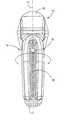
- FIG. 1is the front longitudinal view of the ultrasound probe with accelerometer of this invention.
- FIG. 2is the back longitudinal view of the ultrasound probe of FIG. 1 .
- FIG. 3is the bottom end view of the ultrasound probe of FIG. 1 .
- FIG. 4a longitudinal cross-section of the internal components of the ultrasound probe of FIG. 1 .
- FIG. 5is a schematic view of the Micro electro-mechanical systems accelerometer integrated circuit(MEMS)
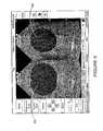
- FIG. 6is side-by-side view taken at right angles to each other of a human bladder (Transverse and Sagittal planes)
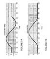
- FIG. 7Ais a graph showing a measurement of the accelerometer graphically displaying velocity and distance traveled which shows that velocity is the integral of accelerometer.
- FIG. 7Bis a graph showing that distance traveled in the integral of velocity (double integral of accelerometer).
- FIG. 8Ais a longitudinal view of an end cavity ultrasound probe with accelerometer.
- FIG. 8Bis longitudinal view of a sidefire ultrasound probe with accelerometer.
- Probe casing22. Interface Printed circuit board 24. Motor 26. Transducer 28. Transducer cradle 30. Scanner connector 32. Micro electro-mechanical systems accelerometer integrated circuit (MEMS) 34. Logic buffers 36. Probe switch connector Non-volatile memory Transverse plane of bladder 42 Sagittal plane of bladder
- Ultrasound probesnormally consist of a piezoelectric element which is driven by a high voltage pulse to produce a high frequency sound wave between 1-20 MHz.
- the piezoelectric elementmay consist of a number of elements as used in a phased array or electronic probe or a single or annular element mechanically driven.
- FIG. 1illustrates a front longitudinal view of the ultrasound probe with accelerometer 10 of this invention.
- This ultrasound probe with accelerometer 10as shown in the longitudinal cross-section of FIG. 4 consists of the piezoelectric element in a transducer 26 , electric drive motor 24 , interface printed circuit board (PCB 22 , probe switch 12 and outlet connector ( 19 ).
- PCB 22interface printed circuit board
- the transducer 26is a piezoelectric transducer which converts mechanical waves to electrical signals and vice versa. These transducers frequently incorporate a polycrystalline piezoelectric and may be based upon the composition Pb(Zr 1-x ,Ti x )O 3 , generally known as PZT. Other crystals which convert mechanical waves to electrical signals may also be used.
- the printed circuit board 22 shown in FIG. 5acts as the interface between the incoming cable from the ultrasound scanner electronic and the probe element.
- the printed circuit board 22contains the interface electronics containing the non-volatile memory 38 , the micro electro-mechanical systems accelerometer integrated circuit (MEMS) 32 , and clock buffers.
- An accelerometeris a device that measures non-gravitational accelerometers. The accelerometer is detected by mechanically accelerating the accelerometer via its casing.
- the MEMS sensorUnder the influence of external accelerometers that are transmitted via the casing the MEMS sensor deflects from its neutral position. This deflection is measured in an analog or digital manner. Most commonly the capacitance between a set of fixed beams and a set of beams attached to the proof mass is measured. This method is simple, reliable and does not require additional process steps making it inexpensive.
- An accelerometermeasures the non gravitational acceleration it experiences. It is simplest to consider that the gravitational forces accelerate the whole accelerometer equally, and therefore give no reading. Non-gravitational acceleration is produced by forces other than gravity or inertial forces. Such forces include all simple mechanical forces. These are transmitted to the accelerometer device through mechanical stress on its mounting.
- the non-volatile memory 38can be used to contain the serial number, probe characteristics, time gain characteristics, last used settings for when probe is interchanged with other types of probe, i.e. abdominal, endocavity, linear etc.
- the accelerometerdetects movement of the probe in three axes and allows detection of the probe 10 when rotated or moved in a linear direction.
- the probe 10could be used to detect movement of the probe in two axes, but the results would be less accurate.
- the probe 10When scanning an organ (such as a bladder) as shown in FIG. 6 and the probe 10 is aligned in the normal direction for scanning that organ and the probe switch 12 is then pressed, it will save the image from that position and mark that position as 0 degrees.
- the probe 10is then rotated through 90 degrees as shown in the sketch below.
- the informationcan be automatically saved or used to open a second window to display the sagittal view, which is the vertical plane passing through the standing body from front to back.
- the two viewscan also be used to calculate the organ volume (such as bladder volume) to a greater accuracy.
- the velocityis the integral of the acceleration measured by the MEMS accelerometer 32 and the distance traveled is the integral of the velocity.
- the linear displacementis interpolated from the accelerometer and deceleration and time of displacement of the probe 10 .
- the image shown in FIG. 6are two scans taken at right angles to each other of the bladder of a person (Transverse and Sagittal planes).By using both images a more accurate valuation of the bladder volume can be made.
- the MEMS accelerometer 32 sensorBy using the MEMS accelerometer 32 sensor the 90° turn in the probe 10 can be detected and the image automatically switched to the other window. This allows the two images to be shown side by side.
- the scancan be started by either pressing the probe switch 12 on the probe 10 or on the START button on the monitor screen as shown in FIG. 6 , the maximum bladder size can be manually or automatically detected.
- Manual detectionis achieved by the operator moving the probe 10 to visually maximize the image of the bladder.
- the operatorplaces the probe 10 approximately over where the bladder should be and then moves the probe in the horizontal or vertical direction to centre the bladder, then moves the probe angularly with the front end of the probe as represented by the fluid chamber 18 remaining in the same position until the maximum bladder area is observed.
- the operatorpresses the probe switch 12 or the STOP/Freeze button on the monitor screen to stop the scan and save the image and instigate the calculation for the bladder volume.
- Automatic detectionis achieved by the operator moving the probe 10 as described in the manual detection. During the scan each frame is compared to see if the image of the bladder area is larger than that in the preceding frame. The frame with the image of the largest bladder area is then stored.
- Pressing the probe switch 12 or the Stop/freeze button on the monitor screen to stop the scanwould instigate the calculation for the bladder volume using the frame image stored with the image of the bladder with the maximum area obtained during the investigation.
- the probe 10 of this inventionhas an orientation spot 14 as shown FIG. 1 which provides the operator with a starting point analogous to a GPS starting point or on a map direction website on the internet.
- the sagittal scancan then be obtained manually when the operator rotates the probe 90° to the previous scan and repeats the process of scanning as just denote the sagittal scan position and another orientation spot or dot 14 or the start/stop button on the monitor denoting the transverse position.
- the operatormoves the probe 10 to visually maximize the image of the bladder. Pressing the probe switch or the Stop/Freeze button on the screen will stop the scan and save the image and instigate the calculation for the bladder volume. However, it could also instigate the calculation for the bladder volume using the transverse and sagittal frame images stored showing the bladder with the maximum area.
- the sagittal scancan also be obtained automatically such that when the operator rotates the probe 10 by 90°.
- the MEMS 32 accelerometer sensorautomatically senses when the probe 10 is rotated 90° to automatically display the sagittal plane on the display either individually or side by side with the transverse scan.
- the frame with the image of the largest bladder areais then stored. Pressing the probe switch 12 or the STOP/Freeze button on the screen to stop the scan will start the calculation for the bladder volume using the images stored with the bladder with the maximum area for transverse and sagittal frames. This method can also apply to other organs such as the prostate.
- FIG. 7AThe non-contact method to measure accelerometer, velocity, and distance traveled is illustrated in FIG. 7A .
- Velocityis the integral of Accelerometer observed.
- the operatorpresses the probe button or the STOP/Freeze button on the screen to stop the scan and save the image and instigate the calculation for the bladder volume.
- Automatic detectionis achieved by the operator moving the probe as described in the manual detection. During the scan each frame is compared to see if the image of the bladder area is larger than that in the preceding frame. The frame with the image of the largest bladder area is then stored.
- Pressing the probe button or the Stop/freeze button on the screen to stop the scanwould instigate the calculation for the bladder volume using the frame image stored with the image of the bladder with the maximum area obtained during the investigation.
- the orientation of the probe 10can be determined by placing an orientation spot or dot 14 as illustrated in FIG. 1 and in the sketch below. It is analogous to the start position of GPS or map directions on some internet websites such as MapquestTM.
- Pressing the probe switch 12 or the START button on the monitor screenstarts the transverse scan so that the maximum bladder size can be detected either manually as described previously or automatically.
- Automatic detectionis achieved by moving the probe 10 to maximize the image of the bladder, each frame is compared to see if the image of the bladder area is larger than that in the preceding frame. The frame with the image of the largest bladder area is then stored.
- the sagittal scancan then be obtained manually when the operator rotates the probe 90° to the previous scan and repeats the process of scanning as just described for the transverse scan.
- the probe 10is usually marked with a spot or dot on the probe to denote the sagittal scan position and another orientation spot or dot 14 or the start/stop button on the monitor denoting the transverse position.
- the operatormoves the probe 10 to visually maximize the image of the bladder. Pressing the probe switch or the Stop/Freeze button on the screen will stop the scan and save the image and instigate the calculation for the bladder volume. However, it could also instigate the calculation for the bladder volume using the transverse and sagittal frame images stored showing the bladder with the maximum area.
- the sagittal scancan also be obtained automatically such that when the operator rotates the probe 10 by 90°.
- the MEMS 32 accelerometer sensorautomatically senses when the probe 10 is rotated 90° to automatically display the sagittal plane on the display either individually or side by side with the transverse scan.
- the frame with the image of the largest bladder areais then stored. Pressing the probe switch 12 or the STOP/Freeze button on the screen to stop the scan will start the calculation for the bladder volume using the images stored with the bladder with the maximum area for transverse and sagittal frames.
- This methodcan also apply to other organs such as the prostate.
- the non-contact method to measure accelerometer, velocity, and distance traveledis illustrated in FIG. 7A .
- Velocityis the integral of Accelerometer as shown in FIG. 7B .
- the distanceis the integral of velocity (double integral of accelerometer.
- Piezo-film(Vibration, shock), AC Response only, Senses many things besides motion (sound, temperature, pressure)
- Endocavity probes as illustrated in FIGS. 8A and 8Bare used for transrectal, pelvic floor and urethra scanning.
- the 90° turncan be automatically detected using the MEMS 32 accelerometer sensor and the image automatically saved.
- an endfire endocavity probeas illustrated in FIG. 8A an arc of sound is emitted in line with the shaft of the probe (A) (in the directions indicated by the arrows), for example to scan a prostate situated in front of the probe . If the probe is rotated through 180° (B) whilst scanning in this mode, then by using a MEMS 32 accelerometer sensor in the probe to sense the angular rotation, a 3D image can be built up.
- a sidefire endocavity probeas the sound is emitted at right angles to the shaft of the probe (C) to image the tissue surrounding the probe.
- Cthe shaft of the probe
- Dthe probe in a linear mode
- 3D imagecan be built up.
- the MEMS 32 accelerometer sensoris used to sense the linear motion. Although the sensor only detects the accelerometer, the linear displacement is interpolated from the accelerometer and deceleration and time of displacement of the probe.
Landscapes
- Health & Medical Sciences (AREA)
- Life Sciences & Earth Sciences (AREA)
- Physics & Mathematics (AREA)
- Engineering & Computer Science (AREA)
- Medical Informatics (AREA)
- Animal Behavior & Ethology (AREA)
- Radiology & Medical Imaging (AREA)
- Nuclear Medicine, Radiotherapy & Molecular Imaging (AREA)
- Biomedical Technology (AREA)
- Heart & Thoracic Surgery (AREA)
- Biophysics (AREA)
- Molecular Biology (AREA)
- Surgery (AREA)
- Pathology (AREA)
- General Health & Medical Sciences (AREA)
- Public Health (AREA)
- Veterinary Medicine (AREA)
- General Physics & Mathematics (AREA)
- Acoustics & Sound (AREA)
- Multimedia (AREA)
- Ultra Sonic Daignosis Equipment (AREA)
Abstract
Description
| 10. | Ultrasound |
| 12. | Probe Switch |
| 14. | |
| 16. | |
| 17. | |
| 18. | |
| 19. | |
| 20. | Probe |
| 22. | Interface Printed |
| 24. | |
| 26. | Transducer |
| 28. | Transducer |
| 30. | |
| 32. | Micro electro-mechanical |
| systems accelerometer integrated | |
| circuit (MEMS) | |
| 34. | |
| 36. | Probe switch connector |
| Non-volatile memory | |
| Transverse plane of | |
| 42 | Sagittal plane of bladder |
Claims (20)
Priority Applications (1)
| Application Number | Priority Date | Filing Date | Title |
|---|---|---|---|
| US13/256,763US8914245B2 (en) | 2009-03-20 | 2010-03-22 | Ultrasound probe with accelerometer |
Applications Claiming Priority (3)
| Application Number | Priority Date | Filing Date | Title |
|---|---|---|---|
| US16191009P | 2009-03-20 | 2009-03-20 | |
| US13/256,763US8914245B2 (en) | 2009-03-20 | 2010-03-22 | Ultrasound probe with accelerometer |
| PCT/GB2010/050480WO2010106379A1 (en) | 2009-03-20 | 2010-03-22 | Ultrasound probe with accelerometer |
Publications (2)
| Publication Number | Publication Date |
|---|---|
| US20110320143A1 US20110320143A1 (en) | 2011-12-29 |
| US8914245B2true US8914245B2 (en) | 2014-12-16 |
Family
ID=42200025
Family Applications (1)
| Application Number | Title | Priority Date | Filing Date |
|---|---|---|---|
| US13/256,763Active2031-02-03US8914245B2 (en) | 2009-03-20 | 2010-03-22 | Ultrasound probe with accelerometer |
Country Status (2)
| Country | Link |
|---|---|
| US (1) | US8914245B2 (en) |
| WO (1) | WO2010106379A1 (en) |
Cited By (6)
| Publication number | Priority date | Publication date | Assignee | Title |
|---|---|---|---|---|
| US20140355377A1 (en)* | 2013-05-31 | 2014-12-04 | eagleyemed, Inc. | Ultrasound image enhancement and super-resolution |
| US10347818B2 (en) | 2016-03-31 | 2019-07-09 | General Electric Company | Method for manufacturing ultrasound transducers |
| WO2021061257A1 (en)* | 2019-09-27 | 2021-04-01 | Google Llc | Automated maternal and prenatal health diagnostics from ultrasound blind sweep video sequences |
| US11368667B2 (en) | 2009-06-17 | 2022-06-21 | 3Shape A/S | Intraoral scanning apparatus |
| US11701208B2 (en) | 2014-02-07 | 2023-07-18 | 3Shape A/S | Detecting tooth shade |
| US11872080B1 (en) | 2020-02-26 | 2024-01-16 | Board Of Trustees Of The University Of Alabama, For And On Behalf Of The University Of Alabama In Huntsville | Multi-modal heart diagnostic system and method |
Families Citing this family (12)
| Publication number | Priority date | Publication date | Assignee | Title |
|---|---|---|---|---|
| EP2528509B1 (en) | 2010-01-29 | 2021-10-13 | University Of Virginia Patent Foundation | Ultrasound for locating anatomy or probe guidance |
| WO2012148985A1 (en) | 2011-04-26 | 2012-11-01 | University Of Virginia Patent Foundation | Bone surface image reconstruction using ultrasound |
| WO2013170053A1 (en) | 2012-05-09 | 2013-11-14 | The Regents Of The University Of Michigan | Linear magnetic drive transducer for ultrasound imaging |
| US20150182198A1 (en)* | 2013-12-27 | 2015-07-02 | General Electric Company | System and method for displaying ultrasound images |
| WO2015110436A1 (en)* | 2014-01-27 | 2015-07-30 | Koninklijke Philips N.V. | An ultrasound imaging system and an ultrasound imaging method |
| US20150327841A1 (en)* | 2014-05-13 | 2015-11-19 | Kabushiki Kaisha Toshiba | Tracking in ultrasound for imaging and user interface |
| WO2016002992A1 (en)* | 2014-07-04 | 2016-01-07 | 한국디지털병원수출사업협동조합 | Image distortion compensation system for three-dimensional ultrasound diagnostic device |
| KR101999829B1 (en) | 2016-04-07 | 2019-08-16 | (주)엠큐브테크놀로지 | Stand-alone type ultrasonic scanner |
| CN106108947A (en)* | 2016-07-18 | 2016-11-16 | 上海市第人民医院 | A kind of system automatically controlling diasonograph |
| EP3613352A1 (en) | 2018-08-21 | 2020-02-26 | Koninklijke Philips N.V. | Systems and methods for performing bi-plane imaging |
| CN112603365B (en)* | 2020-12-18 | 2025-01-07 | 无锡祥生医疗科技股份有限公司 | Switchable ultrasound probes and ultrasound equipment |
| CN115089208B (en)* | 2022-06-27 | 2023-01-06 | 深圳市索诺瑞科技有限公司 | Linear scanning mechanical volume probe |
Citations (41)
| Publication number | Priority date | Publication date | Assignee | Title |
|---|---|---|---|---|
| US3572899A (en)* | 1968-02-13 | 1971-03-30 | Texas Instruments Inc | Acousto-optical modulator |
| US4170142A (en)* | 1977-07-15 | 1979-10-09 | Electric Power Research Institute, Inc. | Linear transducer array and method for both pulse-echo and holographic acoustic imaging |
| US5095752A (en)* | 1988-11-15 | 1992-03-17 | Hitachi, Ltd. | Capacitance type accelerometer |
| US5130937A (en)* | 1990-03-07 | 1992-07-14 | Sundstrand Corporation | Method and apparatus for storing velocity data |
| US5538004A (en)* | 1995-02-28 | 1996-07-23 | Hewlett-Packard Company | Method and apparatus for tissue-centered scan conversion in an ultrasound imaging system |
| US5582173A (en)* | 1995-09-18 | 1996-12-10 | Siemens Medical Systems, Inc. | System and method for 3-D medical imaging using 2-D scan data |
| US6122538A (en) | 1997-01-16 | 2000-09-19 | Acuson Corporation | Motion--Monitoring method and system for medical devices |
| US6142947A (en)* | 1998-12-04 | 2000-11-07 | General Electric Company | Ultrasound probe and related methods of assembly/disassembly |
| US6150947A (en)* | 1999-09-08 | 2000-11-21 | Shima; James Michael | Programmable motion-sensitive sound effects device |
| US6171248B1 (en)* | 1997-02-27 | 2001-01-09 | Acuson Corporation | Ultrasonic probe, system and method for two-dimensional imaging or three-dimensional reconstruction |
| US20010051766A1 (en)* | 1999-03-01 | 2001-12-13 | Gazdzinski Robert F. | Endoscopic smart probe and method |
| US6338716B1 (en) | 1999-11-24 | 2002-01-15 | Acuson Corporation | Medical diagnostic ultrasonic transducer probe and imaging system for use with a position and orientation sensor |
| US6371903B1 (en)* | 2000-06-22 | 2002-04-16 | Technomed Medical Systems, S.A. | Therapy probe |
| US20030176787A1 (en)* | 1999-06-22 | 2003-09-18 | Teratech Corporation | Ultrasound probe with integrated electronics |
| EP1348385A1 (en) | 2002-03-25 | 2003-10-01 | Insightec-Txsonics Ltd. | Positioning systems for guided ultrasound therapy systems |
| US20040264707A1 (en)* | 2001-08-31 | 2004-12-30 | Jun Yang | Steering of directional sound beams |
| US20050193820A1 (en)* | 2004-03-04 | 2005-09-08 | Siemens Medical Solutions Usa, Inc. | Integrated sensor and motion sensing for ultrasound and other devices |
| US20060058676A1 (en)* | 2002-04-17 | 2006-03-16 | Tomoyuki Yagi | Ultrasonic probe in body cavity |
| US7066887B2 (en)* | 2003-10-21 | 2006-06-27 | Vermon | Bi-plane ultrasonic probe |
| US20060235316A1 (en)* | 2002-10-18 | 2006-10-19 | Ungless Gary S | Cardiac monitoring apparatus and method |
| US20070010747A1 (en)* | 2005-05-26 | 2007-01-11 | Sabourin Thomas J | Methods and systems for acquiring ultrasound image data |
| US20070010742A1 (en)* | 2005-05-25 | 2007-01-11 | General Electric Company | Method and system for determining contact along a surface of an ultrasound probe |
| US20070135807A1 (en)* | 2005-12-12 | 2007-06-14 | Richard Wolf Gmbh | Endoscopic Instrument |
| US20080004528A1 (en)* | 2006-01-25 | 2008-01-03 | Fitzsimons Thomas P | Ultrasound medical system and methods |
| US20080146941A1 (en) | 2006-12-13 | 2008-06-19 | Ep Medsystems, Inc. | Catheter Position Tracking for Intracardiac Catheters |
| US20080146932A1 (en) | 2002-06-07 | 2008-06-19 | Vikram Chalana | 3D ultrasound-based instrument for non-invasive measurement of Amniotic Fluid Volume |
| US20080194951A1 (en)* | 2005-04-18 | 2008-08-14 | Koninklijke Philips Electronics N.V. | Ultrasonic Diagnostic Imaging System Configured By Probe Firmware |
| US20080200807A1 (en)* | 2007-02-20 | 2008-08-21 | Accutome Ultrasound, Inc. | Attitude-sensing ultrasound probe |
| US20080249418A1 (en)* | 2007-04-05 | 2008-10-09 | Kabushiki Kaisha Toshiba | Ultrasound diagnosis system including a motor driving multiplane ultrasound probe and image data acquiring method |
| US7443154B1 (en)* | 2003-10-04 | 2008-10-28 | Seektech, Inc. | Multi-sensor mapping omnidirectional sonde and line locator |
| US20090112089A1 (en)* | 2007-10-27 | 2009-04-30 | Bill Barnard | System and method for measuring bladder wall thickness and presenting a bladder virtual image |
| US20090130642A1 (en)* | 2005-12-26 | 2009-05-21 | Hrs Consultant Service, Inc. | Educational Simulator for Transthoracic Echocardiography |
| US20090209860A1 (en)* | 2008-02-19 | 2009-08-20 | Nihon Dempa Kogyo Co., Ltd. | Ultrasonic probe |
| US20090264754A1 (en)* | 2008-04-21 | 2009-10-22 | University Of Washington | Method and apparatus for evaluating osteointegration of medical implants |
| US20090306509A1 (en)* | 2005-03-30 | 2009-12-10 | Worcester Polytechnic Institute | Free-hand three-dimensional ultrasound diagnostic imaging with position and angle determination sensors |
| US20100194692A1 (en)* | 2009-01-30 | 2010-08-05 | Research In Motion Limited | Handheld electronic device having a touchscreen and a method of using a touchscreen of a handheld electronic device |
| US20100201573A1 (en)* | 2009-02-06 | 2010-08-12 | Michael George Lamming | Ranging transceiver based activity monitoring system |
| US20110034806A1 (en)* | 2008-01-09 | 2011-02-10 | The Trustees Of Dartmouth College | Systems And Methods For Combined Ultrasound And Electrical Impedance Imaging |
| US20110248603A1 (en)* | 2010-04-13 | 2011-10-13 | Toshiba Medical Systems Corporation | Ultrasound transducer, ultrasound probe, and a method for manufacturing ultrasound transducers |
| US20120238875A1 (en)* | 2004-11-30 | 2012-09-20 | Eric Savitsky | Embedded Motion Sensing Technology for Integration within Commercial Ultrasound Probes |
| US8366622B2 (en)* | 2004-10-06 | 2013-02-05 | Guided Therapy Systems, Llc | Treatment of sub-dermal regions for cosmetic effects |
- 2010
- 2010-03-22USUS13/256,763patent/US8914245B2/enactiveActive
- 2010-03-22WOPCT/GB2010/050480patent/WO2010106379A1/enactiveApplication Filing
Patent Citations (41)
| Publication number | Priority date | Publication date | Assignee | Title |
|---|---|---|---|---|
| US3572899A (en)* | 1968-02-13 | 1971-03-30 | Texas Instruments Inc | Acousto-optical modulator |
| US4170142A (en)* | 1977-07-15 | 1979-10-09 | Electric Power Research Institute, Inc. | Linear transducer array and method for both pulse-echo and holographic acoustic imaging |
| US5095752A (en)* | 1988-11-15 | 1992-03-17 | Hitachi, Ltd. | Capacitance type accelerometer |
| US5130937A (en)* | 1990-03-07 | 1992-07-14 | Sundstrand Corporation | Method and apparatus for storing velocity data |
| US5538004A (en)* | 1995-02-28 | 1996-07-23 | Hewlett-Packard Company | Method and apparatus for tissue-centered scan conversion in an ultrasound imaging system |
| US5582173A (en)* | 1995-09-18 | 1996-12-10 | Siemens Medical Systems, Inc. | System and method for 3-D medical imaging using 2-D scan data |
| US6122538A (en) | 1997-01-16 | 2000-09-19 | Acuson Corporation | Motion--Monitoring method and system for medical devices |
| US6171248B1 (en)* | 1997-02-27 | 2001-01-09 | Acuson Corporation | Ultrasonic probe, system and method for two-dimensional imaging or three-dimensional reconstruction |
| US6142947A (en)* | 1998-12-04 | 2000-11-07 | General Electric Company | Ultrasound probe and related methods of assembly/disassembly |
| US20010051766A1 (en)* | 1999-03-01 | 2001-12-13 | Gazdzinski Robert F. | Endoscopic smart probe and method |
| US20030176787A1 (en)* | 1999-06-22 | 2003-09-18 | Teratech Corporation | Ultrasound probe with integrated electronics |
| US6150947A (en)* | 1999-09-08 | 2000-11-21 | Shima; James Michael | Programmable motion-sensitive sound effects device |
| US6338716B1 (en) | 1999-11-24 | 2002-01-15 | Acuson Corporation | Medical diagnostic ultrasonic transducer probe and imaging system for use with a position and orientation sensor |
| US6371903B1 (en)* | 2000-06-22 | 2002-04-16 | Technomed Medical Systems, S.A. | Therapy probe |
| US20040264707A1 (en)* | 2001-08-31 | 2004-12-30 | Jun Yang | Steering of directional sound beams |
| EP1348385A1 (en) | 2002-03-25 | 2003-10-01 | Insightec-Txsonics Ltd. | Positioning systems for guided ultrasound therapy systems |
| US20060058676A1 (en)* | 2002-04-17 | 2006-03-16 | Tomoyuki Yagi | Ultrasonic probe in body cavity |
| US20080146932A1 (en) | 2002-06-07 | 2008-06-19 | Vikram Chalana | 3D ultrasound-based instrument for non-invasive measurement of Amniotic Fluid Volume |
| US20060235316A1 (en)* | 2002-10-18 | 2006-10-19 | Ungless Gary S | Cardiac monitoring apparatus and method |
| US7443154B1 (en)* | 2003-10-04 | 2008-10-28 | Seektech, Inc. | Multi-sensor mapping omnidirectional sonde and line locator |
| US7066887B2 (en)* | 2003-10-21 | 2006-06-27 | Vermon | Bi-plane ultrasonic probe |
| US20050193820A1 (en)* | 2004-03-04 | 2005-09-08 | Siemens Medical Solutions Usa, Inc. | Integrated sensor and motion sensing for ultrasound and other devices |
| US8366622B2 (en)* | 2004-10-06 | 2013-02-05 | Guided Therapy Systems, Llc | Treatment of sub-dermal regions for cosmetic effects |
| US20120238875A1 (en)* | 2004-11-30 | 2012-09-20 | Eric Savitsky | Embedded Motion Sensing Technology for Integration within Commercial Ultrasound Probes |
| US20090306509A1 (en)* | 2005-03-30 | 2009-12-10 | Worcester Polytechnic Institute | Free-hand three-dimensional ultrasound diagnostic imaging with position and angle determination sensors |
| US20080194951A1 (en)* | 2005-04-18 | 2008-08-14 | Koninklijke Philips Electronics N.V. | Ultrasonic Diagnostic Imaging System Configured By Probe Firmware |
| US20070010742A1 (en)* | 2005-05-25 | 2007-01-11 | General Electric Company | Method and system for determining contact along a surface of an ultrasound probe |
| US20070010747A1 (en)* | 2005-05-26 | 2007-01-11 | Sabourin Thomas J | Methods and systems for acquiring ultrasound image data |
| US20070135807A1 (en)* | 2005-12-12 | 2007-06-14 | Richard Wolf Gmbh | Endoscopic Instrument |
| US20090130642A1 (en)* | 2005-12-26 | 2009-05-21 | Hrs Consultant Service, Inc. | Educational Simulator for Transthoracic Echocardiography |
| US20080004528A1 (en)* | 2006-01-25 | 2008-01-03 | Fitzsimons Thomas P | Ultrasound medical system and methods |
| US20080146941A1 (en) | 2006-12-13 | 2008-06-19 | Ep Medsystems, Inc. | Catheter Position Tracking for Intracardiac Catheters |
| US20080200807A1 (en)* | 2007-02-20 | 2008-08-21 | Accutome Ultrasound, Inc. | Attitude-sensing ultrasound probe |
| US20080249418A1 (en)* | 2007-04-05 | 2008-10-09 | Kabushiki Kaisha Toshiba | Ultrasound diagnosis system including a motor driving multiplane ultrasound probe and image data acquiring method |
| US20090112089A1 (en)* | 2007-10-27 | 2009-04-30 | Bill Barnard | System and method for measuring bladder wall thickness and presenting a bladder virtual image |
| US20110034806A1 (en)* | 2008-01-09 | 2011-02-10 | The Trustees Of Dartmouth College | Systems And Methods For Combined Ultrasound And Electrical Impedance Imaging |
| US20090209860A1 (en)* | 2008-02-19 | 2009-08-20 | Nihon Dempa Kogyo Co., Ltd. | Ultrasonic probe |
| US20090264754A1 (en)* | 2008-04-21 | 2009-10-22 | University Of Washington | Method and apparatus for evaluating osteointegration of medical implants |
| US20100194692A1 (en)* | 2009-01-30 | 2010-08-05 | Research In Motion Limited | Handheld electronic device having a touchscreen and a method of using a touchscreen of a handheld electronic device |
| US20100201573A1 (en)* | 2009-02-06 | 2010-08-12 | Michael George Lamming | Ranging transceiver based activity monitoring system |
| US20110248603A1 (en)* | 2010-04-13 | 2011-10-13 | Toshiba Medical Systems Corporation | Ultrasound transducer, ultrasound probe, and a method for manufacturing ultrasound transducers |
Non-Patent Citations (1)
| Title |
|---|
| The International Search Report dated Jun. 23, 2010. |
Cited By (19)
| Publication number | Priority date | Publication date | Assignee | Title |
|---|---|---|---|---|
| US11671582B2 (en) | 2009-06-17 | 2023-06-06 | 3Shape A/S | Intraoral scanning apparatus |
| US12375638B2 (en) | 2009-06-17 | 2025-07-29 | 3Shape A/S | Intraoral scanning apparatus |
| US12355936B2 (en) | 2009-06-17 | 2025-07-08 | 3Shape A/S | Intraoral scanning apparatus |
| US11368667B2 (en) | 2009-06-17 | 2022-06-21 | 3Shape A/S | Intraoral scanning apparatus |
| US11539937B2 (en) | 2009-06-17 | 2022-12-27 | 3Shape A/S | Intraoral scanning apparatus |
| US11622102B2 (en) | 2009-06-17 | 2023-04-04 | 3Shape A/S | Intraoral scanning apparatus |
| US11831815B2 (en) | 2009-06-17 | 2023-11-28 | 3Shape A/S | Intraoral scanning apparatus |
| US12335456B2 (en) | 2009-06-17 | 2025-06-17 | 3Shape A/S | Intraoral scanning apparatus |
| US12155812B2 (en) | 2009-06-17 | 2024-11-26 | 3Shape A/S | Intraoral scanning apparatus |
| US20150092515A1 (en)* | 2013-05-31 | 2015-04-02 | eagleyemed, Inc. | Ultrasound image enhancement and super-resolution |
| US9188664B2 (en)* | 2013-05-31 | 2015-11-17 | eagleyemed, Inc. | Ultrasound image enhancement and super-resolution |
| US9194941B2 (en)* | 2013-05-31 | 2015-11-24 | Eagleyemed Inc. | Ultrasound image enhancement and super-resolution |
| US20140355377A1 (en)* | 2013-05-31 | 2014-12-04 | eagleyemed, Inc. | Ultrasound image enhancement and super-resolution |
| US11723759B2 (en) | 2014-02-07 | 2023-08-15 | 3Shape A/S | Detecting tooth shade |
| US11707347B2 (en) | 2014-02-07 | 2023-07-25 | 3Shape A/S | Detecting tooth shade |
| US11701208B2 (en) | 2014-02-07 | 2023-07-18 | 3Shape A/S | Detecting tooth shade |
| US10347818B2 (en) | 2016-03-31 | 2019-07-09 | General Electric Company | Method for manufacturing ultrasound transducers |
| WO2021061257A1 (en)* | 2019-09-27 | 2021-04-01 | Google Llc | Automated maternal and prenatal health diagnostics from ultrasound blind sweep video sequences |
| US11872080B1 (en) | 2020-02-26 | 2024-01-16 | Board Of Trustees Of The University Of Alabama, For And On Behalf Of The University Of Alabama In Huntsville | Multi-modal heart diagnostic system and method |
Also Published As
| Publication number | Publication date |
|---|---|
| US20110320143A1 (en) | 2011-12-29 |
| WO2010106379A1 (en) | 2010-09-23 |
Similar Documents
| Publication | Publication Date | Title |
|---|---|---|
| US8914245B2 (en) | Ultrasound probe with accelerometer | |
| US6045508A (en) | Ultrasonic probe, system and method for two-dimensional imaging or three-dimensional reconstruction | |
| JP4294376B2 (en) | Ultrasonic diagnostic probe device | |
| KR101999829B1 (en) | Stand-alone type ultrasonic scanner | |
| CN110997165B (en) | Capacitive Micromachined Ultrasonic Transducer (CMUT) apparatus and control method | |
| WO2006046471A1 (en) | Capacitive micromachined ultrasonic transducer and intracorporeal ultrasound diagnostic system using same | |
| JPH07114775B2 (en) | Ultrasonic lumen diagnostic device | |
| JP2008073391A (en) | Ultrasonic diagnostic apparatus | |
| US20180085090A1 (en) | Ultrasound diagnosis apparatus and method of operating the same | |
| US20160015361A1 (en) | Ultrasound probe for puncture needle and ultrasound diagnostic device using same | |
| JPWO2018105366A1 (en) | Ultrasonic diagnostic apparatus and control method of ultrasonic diagnostic apparatus | |
| JP2002253549A (en) | Ultrasonic image pickup device and method, and probe | |
| JP2012050516A (en) | Portable ultrasonic diagnostic apparatus | |
| JPH0523332A (en) | Probe and ultrasonic diagnosing apparatus using the same | |
| WO2018055841A1 (en) | Ultrasound diagnostic device and method for control of ultrasound diagnostic device | |
| JPH07222744A (en) | Ultrasonic diagnostic equipment | |
| US20160317125A1 (en) | Ultrasonic device unit, probe, electronic apparatus, and ultrasonic diagnostic apparatus | |
| US20040254466A1 (en) | Apparatus and method for real time three-dimensional ultrasound imaging | |
| KR102180465B1 (en) | Supporting device of ultrasound probe, Handfree ultrasound probe comprising the same and Method of operating Handfree ultrasound probe | |
| JP7737184B2 (en) | Ultrasonic scanner and method for correcting ultrasonic signals in said ultrasonic scanner | |
| KR101053286B1 (en) | Ultrasonic probes and ultrasonic diagnostic equipment | |
| JP2011056103A (en) | Ultrasonic probe and ultrasonic diagnostic device | |
| JP2009066046A (en) | Ultrasonograph | |
| JP2001327501A (en) | Ultrasonic probe for inside of body cavity and ultrasonic diagnostic device using the same | |
| EP3031397B1 (en) | Ultrasound imaging apparatus |
Legal Events
| Date | Code | Title | Description |
|---|---|---|---|
| AS | Assignment | Owner name:MEDIWATCH UK LIMITED, UNITED KINGDOM Free format text:ASSIGNMENT OF ASSIGNORS INTEREST;ASSIGNOR:HOPKINS, ANDREW DAVID;REEL/FRAME:026911/0980 Effective date:20110915 | |
| STCF | Information on status: patent grant | Free format text:PATENTED CASE | |
| AS | Assignment | Owner name:LABORIE MEDICAL TECHNOLOGIES EUROPE LIMITED, UNITE Free format text:ASSIGNMENT OF ASSIGNORS INTEREST;ASSIGNOR:MEDIWATCH UK LIMITED;REEL/FRAME:039138/0563 Effective date:20160628 | |
| FEPP | Fee payment procedure | Free format text:ENTITY STATUS SET TO SMALL (ORIGINAL EVENT CODE: SMAL) | |
| MAFP | Maintenance fee payment | Free format text:PAYMENT OF MAINTENANCE FEE, 4TH YR, SMALL ENTITY (ORIGINAL EVENT CODE: M2551) Year of fee payment:4 | |
| AS | Assignment | Owner name:LABORIE MEDICAL TECHNOLOGIES CORPORATION, NEW HAMPSHIRE Free format text:NUNC PRO TUNC ASSIGNMENT;ASSIGNOR:LABORIE MEDICAL TECHNOLOGIES CANADA ULC;REEL/FRAME:055575/0515 Effective date:20210304 | |
| FEPP | Fee payment procedure | Free format text:ENTITY STATUS SET TO UNDISCOUNTED (ORIGINAL EVENT CODE: BIG.); ENTITY STATUS OF PATENT OWNER: LARGE ENTITY | |
| MAFP | Maintenance fee payment | Free format text:PAYMENT OF MAINTENANCE FEE, 8TH YEAR, LARGE ENTITY (ORIGINAL EVENT CODE: M1552); ENTITY STATUS OF PATENT OWNER: LARGE ENTITY Year of fee payment:8 | |
| AS | Assignment | Owner name:JPMORGAN CHASE BANK, N.A., AS ADMINISTRATIVE AGENT, ILLINOIS Free format text:SECURITY INTEREST;ASSIGNORS:CLINICAL INNOVATIONS, LLC;COGENTIX MEDICAL, INC.;UROPLASTY, LLC;AND OTHERS;REEL/FRAME:066986/0500 Effective date:20240329 |