US8913978B2 - RTWO-based down converter - Google Patents
RTWO-based down converterDownload PDFInfo
- Publication number
- US8913978B2 US8913978B2US12/100,391US10039108AUS8913978B2US 8913978 B2US8913978 B2US 8913978B2US 10039108 AUS10039108 AUS 10039108AUS 8913978 B2US8913978 B2US 8913978B2
- Authority
- US
- United States
- Prior art keywords
- phase
- phases
- pair
- mixer
- signal
- Prior art date
- Legal status (The legal status is an assumption and is not a legal conclusion. Google has not performed a legal analysis and makes no representation as to the accuracy of the status listed.)
- Active, expires
Links
- 230000005540biological transmissionEffects0.000claimsdescription10
- 238000000034methodMethods0.000claimsdescription7
- 230000001902propagating effectEffects0.000claims2
- 230000001172regenerating effectEffects0.000claims2
- 229910044991metal oxideInorganic materials0.000claims1
- 150000004706metal oxidesChemical class0.000claims1
- 239000004065semiconductorSubstances0.000claims1
- 238000006243chemical reactionMethods0.000description4
- 238000005516engineering processMethods0.000description4
- 238000010586diagramMethods0.000description3
- 230000003595spectral effectEffects0.000description3
- 230000000737periodic effectEffects0.000description2
- 230000007274generation of a signal involved in cell-cell signalingEffects0.000description1
- 230000010355oscillationEffects0.000description1
- 235000014366other mixerNutrition0.000description1
- 238000005191phase separationMethods0.000description1
- 230000008929regenerationEffects0.000description1
- 238000011069regeneration methodMethods0.000description1
Images


Classifications
- H—ELECTRICITY
- H03—ELECTRONIC CIRCUITRY
- H03D—DEMODULATION OR TRANSFERENCE OF MODULATION FROM ONE CARRIER TO ANOTHER
- H03D7/00—Transference of modulation from one carrier to another, e.g. frequency-changing
- H03D7/16—Multiple-frequency-changing
- H03D7/165—Multiple-frequency-changing at least two frequency changers being located in different paths, e.g. in two paths with carriers in quadrature
- H—ELECTRICITY
- H03—ELECTRONIC CIRCUITRY
- H03B—GENERATION OF OSCILLATIONS, DIRECTLY OR BY FREQUENCY-CHANGING, BY CIRCUITS EMPLOYING ACTIVE ELEMENTS WHICH OPERATE IN A NON-SWITCHING MANNER; GENERATION OF NOISE BY SUCH CIRCUITS
- H03B27/00—Generation of oscillations providing a plurality of outputs of the same frequency but differing in phase, other than merely two anti-phase outputs
Definitions
- This inventionrelates generally to mixers in radio frequency applications and more particularly to mixers using multiphase reduced frequency conversion techniques.
- a rotary traveling wave oscillatoris described in U.S. Pat. No. 6,556,089, which is incorporated by reference into the present application.
- a wave frontmoves around a closed, differential loop, reversing its polarity in each transit of the loop.
- the wave front traveling on the loopis established and maintained by a plurality of regeneration elements, such as back to back inverters, distributed about the entire loop.
- a differential clock signalis available by making a connection to that point.
- the frequency of the clock signalis determined by the electrical size of the loop, by which is meant the time it takes to make a lapse around the loop, given the loop's loaded transmission line characteristics.
- the rotary clock technologymakes it possible to obtain a large number of clock phases from a single physical circuit, creating new architecture possibilities.
- a common solutionis a ring oscillator.
- the phases orderis defined by the circuit order itself.
- ring oscillatorshave a limited number of phases available, determined mostly by the time delay of the inverter used.
- the spectral purity and the current/power consumptionare known to be critical limitations for the ring oscillator.
- generation of multiple phasesis also possible by injecting multiple oscillators together in such a way that they are operating at the same frequency, but with a well-known phase delay between them.
- the I/Q (90 degree out of phase) signal generationis a common requirement for wireless systems with modern digital modulation. This solution is practical if a low number of phases is needed.
- the rotary clockis ideal for multiple phase generation, the time delay between two phases being mostly defined by the transmission line and the capacitive loading. This time can be significantly lower than the minimum time delay of an inverter for the technology used and the spectral purity of the phases is comparable or better than the standard LC tank solution.
- FIG. 1Ashows a prior art conversion, receiver A, and FIG. 1B shows a representative architecture of the present invention, receiver B;
- FIG. 2shows an implementation of a N multi-phase mixer
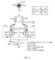
- FIG. 3shows a representative timing diagram with 8 phases
- FIG. 4Ashows an implementation of a mixer circuit with 2 phases and with eight phases.
- One embodiment of the present inventionis a multiphase mixer that includes a rotary traveling wave oscillator, a first mixer circuit, and a second mixer circuit.
- the rotary traveling wave oscillatorgenerates a first plurality N/2 phases and a second plurality of N/2 phases. Each phase has a frequency that is less than the incoming radio frequency signal by a factor of N/2. Each of the first plurality of phases is 90° out of phase with each of the second plurality of phases respectively.
- the first mixer circuitreceives the incoming radio frequency signal and the first plurality of phases from the rotary traveling wave oscillator and generates an output which is the first down converted signal.
- the second mixer circuitreceives the incoming radio frequency signal and the second plurality of phases and generates a second down converted signal.
- the first and second mixer circuitsinclude a first and second pairs of CMOS transistors where in each pair the transistors have their channels in series between first and second voltage sources.
- the first pairhas its first and second gates connected, respectively, to first and second phases from the rotary oscillator and the second pair has its first and second gates connected, respectively, to said second and first phases.
- the output of each mixer circuitis present at the drains of each pair of transistors.
- the rotary clockis applicable to the 60 GHz wireless HD standard, which is technically a very challenging standard for today's CMOS technologies.
- a key conceptis that, instead of operating the clock at 60 GHz, the clock operates at a lower frequency but has multiple phases so that access to the time resolution represented by a 60 GHz clock is still possible, but with low cost standard technology.
- Using a lower frequencyoffers many advantages in term of power, dc offset (LO leakage), reciprocal mixing.
- the present inventionis directed towards circuitry that can achieve direct-conversion (homodyne architecture) of a high frequency signal (at w rf ) with a local oscillator (LO), delivering multiple phases (N phases) oscillating at a lower frequency (2 ⁇ w rf /N) in conjunction with a multi-phase mixer.
- LOlocal oscillator
- the sine and the cosine with a frequency w rfare equivalent to the weighted product of N/2 ⁇ 1 sine waves at a frequency w rf /(N/2).
- Using a lower frequency for the LOoffers at least two advantages: (i) there is low LO leakage (less DC offset), and (ii) the oscillation frequency for the local oscillator is lower.
- Receiver A 10includes an RF filter 12 connected to the receiving antenna 14 , an LNA 16 which amplifies the output of the RF filter 12 and a pair of single-phase mixers 18 , 20 .
- One of the mixers, the sine mixer 18mixes the output of the LNA 16 with a local oscillator 22 single phase sine signal 24 .
- the other mixer, the cosine mixer 20mixes the output of the LNA 16 with a local oscillator 22 single phase cosine signal 26 .
- Each output of the sine and cosine mixers 18 , 20is applied to a low pass filter 28 , 30 , one LPF 28 output generating the I signal 32 and the other LPF 30 output generating the Q signal 34 .
- Receiver B 40 in FIG. 1Bincludes an RF filter 42 connected to the receiving antenna 44 , an LNA 46 which amplifies the output of the RF filter 42 , and a pair of multi-phase mixers 48 , 50 .
- One of the multiphase mixers 48operates with N/2 sine phases 54 and the other multiphase mixer 50 operates with N/2 cosine phases 56 .
- the output of sine mixer 48is applied to an LPF 58 to generate the I signal 62 and the output of the cosine mixer 50 is applied to an LPF 60 to generate the Q signal 64 .
- the Local Oscillator 52 in Receiver B 40is a Rotary Traveling Wave Oscillator operating at a frequency w rf /(N/2) whereas the local oscillator 22 in Receiver A 10 operates at a frequency w rf .
- the Rotary Traveling Wave Oscillator 52operates at a frequency that is a factor (N/2) ⁇ 1 of the frequency of the local oscillator 22 in Receiver A.
- FIG. 3shows a representative timing diagram for the case of 8 phases. Also shown are the equivalent clocks represented by the availability of the multiple phases. Using an overlap between a particular phase and one that is 5 phases away, produces eight unique overlapping times (shown as shaded portions).
- FIG. 4Ashows an implementation of a mixer circuit 100 with two phases and FIG. 4B shows a mixer circuit 150 with eight phases.
- the two-phase mixer circuit 100 in FIG. 4Aincludes a pair of I-to-V blocks 102 , 104 , each providing a current-to-voltage conversion. Implementations of the I-to-V block include a resistor, transistor, or the input of an operational amplifier properly configured.
- the two-phase mixer 100also includes a pair of transistors 106 , 108 and a current source 110 , forming a differential pair, which develops a differential output 112 using the I-to-V blocks 106 , 108 .
- the current source 110is a biased transistor, as shown.
- the two phases, EQ_CLK 114 and EQ_CLKx 116to be mixed are provided to the gates of the differential pair transistors 106 , 108 .
- the 8-phase mixer 150 in FIG. 4Bincludes two 8-phase balanced mixers 152 , 154 .
- Each of the 8-phase mixersincludes four two-phase mixers, one with mixers 156 , 158 , 160 , 162 and one with mixers 164 , 166 , 168 , 170 , each combining a pair of phases that are 5 (mod 8) phase steps away from each other.
- the first 8-phase mixer (left side) 152combines phases (0,5), (2,7), (4,1), (6,3).
- the second 8-phase mixer (right side) 154combines phases (1,6), (3,0), (5,2), (7,4).
- the timing diagram in FIG. 3shows the overlapping times for each of these phase combinations. With eight phase combinations, there are eight unique overlapping times, the 8-phase mixer in FIG. 4 thus operating at a frequency that is four times the frequency of the 2-phase mixer.
- FIG. 2shows an implementation of a N multi-phase mixer 48 , 50 .
- the N-phase mixerincludes I-to-V converters 102 and 104 and two N-phase mixers 80 and 82 .
- Each mixerincludes N/2 two-phase mixers, one with mixers 84 a , 84 b - m , 84 n and the other with 86 a , 86 b - m , 86 n .
- Each of the mixerscombines a pair of phases that are N/2+1 phase steps away from each other.
- mixer 86 acombines phase 2k+1 with [N/2+2(k+1)] mod N and mixer 86 n combines phase 1 with phase [N/2+2].
- the even phases [0 . . . (N ⁇ 2)]are combined with the odd phases [1 . . . N ⁇ 1] where the latter set is rotated to create the minimum phase overlap in each mixer.
- the odd phases [(N ⁇ 1) . . . 1]are combined with the even phases [(N ⁇ 2) . . . 0] where the latter set is rotated to create the minimum phase overlap in each mixer.
Landscapes
- Engineering & Computer Science (AREA)
- Power Engineering (AREA)
- Superheterodyne Receivers (AREA)
- Manipulation Of Pulses (AREA)
Abstract
Description
This application claims priority to U.S. Provisional Application Ser. No. 60/910,809, filed Apr. 9, 2007, and titled “RTWO-BASED DOWN CONVERTER ”, which provisional application is incorporated by reference into the present application.
This invention relates generally to mixers in radio frequency applications and more particularly to mixers using multiphase reduced frequency conversion techniques.
A rotary traveling wave oscillator is described in U.S. Pat. No. 6,556,089, which is incorporated by reference into the present application. In that patent, a wave front moves around a closed, differential loop, reversing its polarity in each transit of the loop. The wave front traveling on the loop is established and maintained by a plurality of regeneration elements, such as back to back inverters, distributed about the entire loop. At any point on the differential loop, a differential clock signal is available by making a connection to that point. The frequency of the clock signal is determined by the electrical size of the loop, by which is meant the time it takes to make a lapse around the loop, given the loop's loaded transmission line characteristics.
The rotary clock technology makes it possible to obtain a large number of clock phases from a single physical circuit, creating new architecture possibilities.
For those architectures that need several phases (more than 2) simultaneously, a common solution is a ring oscillator. In that case, the phases order is defined by the circuit order itself. However, ring oscillators have a limited number of phases available, determined mostly by the time delay of the inverter used. Also, the spectral purity and the current/power consumption are known to be critical limitations for the ring oscillator. For applications that need good spectral purity and low power consumption, generation of multiple phases is also possible by injecting multiple oscillators together in such a way that they are operating at the same frequency, but with a well-known phase delay between them. The I/Q (90 degree out of phase) signal generation is a common requirement for wireless systems with modern digital modulation. This solution is practical if a low number of phases is needed.
The rotary clock is ideal for multiple phase generation, the time delay between two phases being mostly defined by the transmission line and the capacitive loading. This time can be significantly lower than the minimum time delay of an inverter for the technology used and the spectral purity of the phases is comparable or better than the standard LC tank solution.
These and other features, aspects and advantages of the present invention will become better understood with regard to the following description, appended claims, and accompanying drawings where:
One embodiment of the present invention is a multiphase mixer that includes a rotary traveling wave oscillator, a first mixer circuit, and a second mixer circuit. The rotary traveling wave oscillator generates a first plurality N/2 phases and a second plurality of N/2 phases. Each phase has a frequency that is less than the incoming radio frequency signal by a factor of N/2. Each of the first plurality of phases is 90° out of phase with each of the second plurality of phases respectively. The first mixer circuit receives the incoming radio frequency signal and the first plurality of phases from the rotary traveling wave oscillator and generates an output which is the first down converted signal. The second mixer circuit receives the incoming radio frequency signal and the second plurality of phases and generates a second down converted signal.
In one embodiment, the first and second mixer circuits include a first and second pairs of CMOS transistors where in each pair the transistors have their channels in series between first and second voltage sources. The first pair has its first and second gates connected, respectively, to first and second phases from the rotary oscillator and the second pair has its first and second gates connected, respectively, to said second and first phases. The output of each mixer circuit is present at the drains of each pair of transistors.
The rotary clock is applicable to the 60 GHz wireless HD standard, which is technically a very challenging standard for today's CMOS technologies. A key concept is that, instead of operating the clock at 60 GHz, the clock operates at a lower frequency but has multiple phases so that access to the time resolution represented by a 60 GHz clock is still possible, but with low cost standard technology. Using a lower frequency offers many advantages in term of power, dc offset (LO leakage), reciprocal mixing.
The present invention is directed towards circuitry that can achieve direct-conversion (homodyne architecture) of a high frequency signal (at wrf) with a local oscillator (LO), delivering multiple phases (N phases) oscillating at a lower frequency (2·wrf/N) in conjunction with a multi-phase mixer.
The concept behind that circuit is that mixing a single phase high frequency periodic signal is mathematically equivalent to mixing a set of multiphase reduced frequency periodic signals.
Mathematically, the sine and the cosine with a frequency wrfare equivalent to the weighted product of N/2−1 sine waves at a frequency wrf/(N/2).
Using a lower frequency for the LO offers at least two advantages: (i) there is low LO leakage (less DC offset), and (ii) the oscillation frequency for the local oscillator is lower.
The proposed architecture is presented inFIG. 1B . Thereceiver A 10 inFIG. 1A is the standard implementation whereas thereceiver B 40 takes advantage of the availability of the multiple phases of the rotary clock.Receiver A 10 includes anRF filter 12 connected to thereceiving antenna 14, an LNA16 which amplifies the output of theRF filter 12 and a pair of single-phase mixers sine mixer 18, mixes the output of theLNA 16 with alocal oscillator 22 singlephase sine signal 24. The other mixer, thecosine mixer 20, mixes the output of theLNA 16 with alocal oscillator 22 singlephase cosine signal 26. Each output of the sine andcosine mixers low pass filter 28,30, one LPF28 output generating theI signal 32 and theother LPF 30 output generating theQ signal 34.
The 8-phase mixer 150 inFIG. 4B includes two 8-phasebalanced mixers mixers mixers
The timing diagram inFIG. 3 shows the overlapping times for each of these phase combinations. With eight phase combinations, there are eight unique overlapping times, the 8-phase mixer inFIG. 4 thus operating at a frequency that is four times the frequency of the 2-phase mixer.
Although the present invention has been described in considerable detail with reference to certain preferred versions thereof, other versions are possible. Therefore, the spirit and scope of the appended claims should not be limited to the description of the preferred versions contained herein.
Claims (19)
1. A multiphase mixer comprising:
a rotary traveling wave oscillator configured to generate a rotary traveling wave oscillator signal having a plurality of N number of phases, each phase oscillating at a frequency that is less than a frequency of an incoming radio signal by a factor of N/2, said plurality of phases including a first plurality of phases and a second plurality of phases, said first plurality of phases being sine phases and said second plurality of phases being cosine phases, wherein the rotary travelling wave oscillator comprises:
a differential transmission line in a closed loop, the differential transmission line including an odd number of one or more cross-overs configured to reverse the polarity of a wave propagating through the differential transmission line; and
a plurality of regenerative devices electrically connected along a path of the differential transmission line;
a first mixer circuit having an input configured to receive the incoming radio frequency signal and being coupled to receive the first plurality of phases from the rotary traveling wave oscillator, said first mixer circuit having an output that generates a first down converted signal; and
a second mixer circuit having an input configured to receive the incoming radio frequency signal and being coupled to receive the second plurality of phases from the rotary traveling wave oscillator, said second mixer circuit having an output that generates a second down converted signal,
wherein the first mixer circuit comprises a first plurality of phase-pair combining circuits, wherein the first plurality of phase-pair combining circuits combines pairs of phases in said plurality of phases with the incoming radio frequency signal to generate a first mixed output, wherein a first phase and a second phase of each pair of phases differ by N/2+1 phase steps.
2. The multiphase mixer as recited inclaim 1 , wherein the down converted signals are baseband signals.
3. The multiphase mixer as recited inclaim 1 ,
wherein each of the first and second mixer circuits includes N/2 phase-pair combining circuits,
wherein each phase-pair combining circuit has a first pair of transistors in a CMOS configuration and a second pair of transistors in a CMOS configuration, each transistor having a source, a drain, a gate, and a channel being defined between the source and drain,
wherein said first pair of transistors and said second pair of transistors are each configured with their channels in series between a first voltage source and a second voltage source, said first and second gates of the first pair of transistors connected to a first phase and a second phase, respectively, of the rotary traveling wave oscillator, and said first and second gates of the second pair of transistors connected to said second phase and said first phase, respectively, of the rotary traveling wave oscillator, said second phase being displaced (N/2+1) phase steps from the first phase, and
wherein the differential output of each mixer circuit is present between the drains of each pair of transistors.
4. The multiphase mixer recited inclaim 1 , wherein each of the first and second mixer circuits includes N/2 phase-pair combining circuits, said phase-pair combining circuit being divided into two sections, each having N/2 phase-pair combining circuits, a first section of the two sections being coupled to N/2 phase signals from the rotary traveling wave oscillator, said N/2 phase signals being combined to obtain a first set of N/2 equally spaced phases, a second section of the two sections being coupled to N/2 phase signals from the rotary traveling wave oscillator, said N/2 phase signals being combined to obtain a second set of N/2 equally spaced phases, each phase in the second set being shifted by a phase step of 1/N from the first set.
5. The multiphase mixer recited inclaim 1 , wherein each of the first and second mixer circuits includes N/2 phase-pair combining circuits, said N/2 phase-pair combining circuits being divided into two sections, each having N/2 phase-pair combining circuits, a first section of the two sections being coupled to N/2 phase pair signals from the rotary traveling wave oscillator, each phase pair having phases 2k, (2k+N/2+1) mod N, respectively, where k is an positive integer with a range from 0 to N/2−1, a second section of the two sections being coupled to N/2 phase signals from the rotary traveling wave oscillator, each phase pair having phases 2k+1, (2k+1)+(N/2+1) mod N, respectively, where k is a positive integer with a range from 0 to N/2−1.
6. The multiphase mixer recited inclaim 1 ,
wherein each of the first and second mixer circuits includes N/2 phase-pair combining circuits,
wherein each of the first and second mixer circuits includes a current source connected between the N/2 phase-pair combining circuits and a reference voltage, and
wherein the current source receives the incoming radio frequency signal.
7. The multiphase mixer as recited inclaim 1 , wherein the first mixed output is based on an overlap of the first phase and the second phase of each pair of phases.
8. The multiphase mixer as recited inclaim 1 , wherein N is equal to 8, wherein the plurality of phases comprises a first phase (CLK0), a second phase (CLK1), a third phase (CLK2), a fourth phase (CLK3), a fifth phase (CLK4), a sixth phase (CLK5), a seventh phase (CLK6), and an eighth phase (CLK7), wherein the first plurality of phase-pair combining circuits comprises:
a first phase-pair combining circuit configured to combine the first phase (CLK0) and the sixth phase (CLK5);
a second phase-pair combining circuit configured to combine the third phase (CLK2) and the eighth phase (CLK7);
a third phase-pair combining circuit configured to combine the fifth phase (CLK4) and the second phase (CLK1); and
a fourth phase-pair combining circuit configured to combine the seventh phase (CLK6) and the fourth phase (CLK3).
9. The multiphase mixer as recited inclaim 1 , wherein each of the first plurality of phase-pair combining circuits comprises a first metal oxide semiconductor (MOS) transistor and a second MOS transistor electrically connected in series, wherein a gate of the first MOS transistor receives the first phase, and wherein a gate of the second MOS transistor receives the second phase.
10. The multiphase mixer as recited inclaim 1 , wherein the second mixer circuit comprises a second plurality of phase-pair combining circuits, wherein the second plurality of phase-pair combining circuits combines pairs of phases in said plurality of phases with the incoming radio frequency signal to form a second mixed output, wherein a first phase and a second phase of each pair of phases differ by N/2+1 phase steps.
11. The multiphase mixer as recited inclaim 10 , wherein the second mixed output is based on an overlap of the first phase and the second phase of each pair of phases.
12. The multiphase mixer as recited inclaim 10 , wherein the second plurality of phase-pair combining circuits comprises:
a fifth phase-pair combining circuit configured to combine the eighth phase (CLK7) and the fifth phase (CLK4);
a sixth phase-pair combining circuit configured to combine the sixth phase (CLK5) and the third phase (CLK2);
a seventh phase-pair combining circuit configured to combine the fourth phase (CLK3) and the first phase (CLK0); and
an eighth phase-pair combining circuit configured to combine the second phase (CLK1) and the seventh phase (CLK6).
13. The multiphase mixer as recited inclaim 10 , further comprising:
a first low pass filter configured to receive the first down converted signal and to generate an in-phase (I) signal; and
a second low pass filter configured to receive the second down converted signal and to generate a quadrature-phase (Q) signal.
14. A multiphase mixer comprising:
a rotary traveling wave oscillator configured to generate a rotary traveling wave oscillator signal having a plurality of N number of phases, each phase oscillating at a frequency that is less than a frequency of an incoming radio signal by a factor of N/2, said plurality of phases including a first plurality of phases and a second plurality of phases, said first plurality of phases being sine phases and said second plurality of phases being cosine phases;
a first mixer circuit having an input configured to receive the incoming radio frequency signal and being coupled to receive the first plurality of phases from the rotary traveling wave oscillator, said first mixer circuit having an output that generates a first down converted signal; and
a second mixer circuit having an input configured to receive the incoming radio frequency signal and being coupled to receive the second plurality of phases from the rotary traveling wave oscillator, said second mixer circuit having an output that generates a second down converted signal,
wherein each of the first and second mixer circuits includes eight phase-pair combining circuits, said eight phase-pair combining circuits being divided into two sections, each having four phase-pair combining circuits, a first section of the two sections being coupled to eight phase pair signals from the rotary traveling wave oscillator, each phase pair having phases 2k, (2k+5) mod 8, respectively, where k is an positive integer with a range from 0 to 3, a second section of the two sections being coupled to eight phase signals from the rotary traveling wave oscillator, each phase pair having phases 2+1, (2k+1+5) mod 8, respectively, where k is a positive integer with a range from 0 to 3.
15. A method of mixing a signal, said method comprising:
providing a rotary traveling wave oscillator signal having a plurality N phases from a rotary traveling wave oscillator, each oscillating at a frequency that is less than a frequency of an incoming radio signal by a factor of N/2, said plurality of phases including a first plurality of phases and a second plurality of phases, wherein the rotary travelling wave oscillator comprises:
a differential transmission line in a closed loop, the differential transmission line including an odd number of one or more cross-overs configured to reverse the polarity of a wave propagating through the differential transmission line; and
a plurality of regenerative devices electrically connected along a path of the differential transmission line;
combining pairs of phases in the first plurality of phases with the incoming radio frequency signal to form a first mixed output, wherein the phases in each pair differ by N/2+1 phase steps; and
combining pairs of phases in the second plurality of phases with the incoming radio frequency signal to form a second mixed output, wherein the phases in each pair differ by N/2+1 phase steps, and wherein the first mixed output is orthogonal to the second mixed output.
16. The method of mixing a signal recited inclaim 15 , wherein each of the phases of the second plurality of phases differs respectively from each of the phases of the first plurality of phases by one phase step.
17. The method of mixing a signal recited inclaim 15 , wherein there are N/2 phases in the first plurality of phases and N/2 phases in the second plurality of phases.
18. The method of mixing a signal recited inclaim 15 , wherein the step of combining pairs of phases in the first plurality of phases with the incoming radio frequency signal to form a first mixed output includes combining each of N/2 pairs of phases with the incoming radio frequency signal.
19. The method of mixing a signal recited inclaim 15 , wherein the step of combining pairs of phases in the second plurality of phases with the incoming radio frequency signal to form a second mixed output includes combining each of N/2 pairs of phases with the incoming radio frequency signal.
Priority Applications (1)
| Application Number | Priority Date | Filing Date | Title |
|---|---|---|---|
| US12/100,391US8913978B2 (en) | 2007-04-09 | 2008-04-09 | RTWO-based down converter |
Applications Claiming Priority (2)
| Application Number | Priority Date | Filing Date | Title |
|---|---|---|---|
| US91080907P | 2007-04-09 | 2007-04-09 | |
| US12/100,391US8913978B2 (en) | 2007-04-09 | 2008-04-09 | RTWO-based down converter |
Publications (2)
| Publication Number | Publication Date |
|---|---|
| US20090045850A1 US20090045850A1 (en) | 2009-02-19 |
| US8913978B2true US8913978B2 (en) | 2014-12-16 |
Family
ID=40362480
Family Applications (1)
| Application Number | Title | Priority Date | Filing Date |
|---|---|---|---|
| US12/100,391Active2031-07-21US8913978B2 (en) | 2007-04-09 | 2008-04-09 | RTWO-based down converter |
Country Status (1)
| Country | Link |
|---|---|
| US (1) | US8913978B2 (en) |
Families Citing this family (1)
| Publication number | Priority date | Publication date | Assignee | Title |
|---|---|---|---|---|
| US20130016796A1 (en)* | 2011-07-14 | 2013-01-17 | Chih-Hao Sun | Signal modulator and signal modulating method |
Citations (89)
| Publication number | Priority date | Publication date | Assignee | Title |
|---|---|---|---|---|
| US5302920A (en) | 1992-10-13 | 1994-04-12 | Ncr Corporation | Controllable multi-phase ring oscillators with variable current sources and capacitances |
| US5448772A (en) | 1994-08-29 | 1995-09-05 | Motorola, Inc. | Stacked double balanced mixer circuit |
| US5584067A (en) | 1993-12-10 | 1996-12-10 | Motorola, Inc. | Dual traveling wave resonator filter and method |
| US5592126A (en) | 1992-08-20 | 1997-01-07 | U.S. Philips Corporation | Multiphase output oscillator |
| US5652549A (en) | 1995-03-28 | 1997-07-29 | Siemens Aktiengesellschaft | Integrated circuit ring oscillator having line driver with double line feedback |
| US5825211A (en) | 1995-09-29 | 1998-10-20 | Dallas Semiconductor Corporation | Oversampled state machine for jitter tolerant pulse detection |
| US6150886A (en) | 1998-10-20 | 2000-11-21 | Mitsubishi Denki Kabushiki Kaisha | Phase locked loop circuit with multiple combinations which each produce a single phase and multiphase clock signals |
| US6157037A (en) | 1998-12-04 | 2000-12-05 | Photosense, Llc | Sensing device and method for measuring emission time delay during irradiation of targeted samples |
| US6194947B1 (en) | 1998-07-24 | 2001-02-27 | Global Communication Technology Inc. | VCO-mixer structure |
| US6259747B1 (en) | 1997-03-20 | 2001-07-10 | Telefonaktiebolaget L M Ericsson (Publ) | IQ modulator, and associated method |
| US6281759B1 (en) | 1997-05-30 | 2001-08-28 | Lsi Logic Corporation | Digital frequency generation method and apparatus |
| WO2001089088A1 (en) | 2000-05-11 | 2001-11-22 | Multigig Limited | Electronic pulse generator and oscillator |
| US6323737B1 (en) | 2000-01-18 | 2001-11-27 | Raytheon Company | System and method for generating a multi-phase signal with a ring oscillator |
| US6396359B1 (en) | 1999-09-15 | 2002-05-28 | California Institute Of Technology | Tunable, distributed, voltage-controlled oscillator |
| US6426662B1 (en) | 2001-11-12 | 2002-07-30 | Pericom Semiconductor Corp. | Twisted-ring oscillator and delay line generating multiple phases using differential dividers and comparators to match delays |
| US6566968B2 (en) | 1999-12-13 | 2003-05-20 | Broadcom Corporation | Oscillator having multi-phase complementary outputs |
| US20030094976A1 (en)* | 2001-10-22 | 2003-05-22 | Takumi Miyashita | Mixer circuit, receiver circuit, and frequency comparison circuit |
| US20040002315A1 (en)* | 2002-06-28 | 2004-01-01 | Ching-Lang Lin | Harmonic boost signals in up/down direct/super heterodyne conversions for advanced receiver/transmitter architecture |
| US6781424B2 (en) | 1998-07-24 | 2004-08-24 | Gct Semiconductor, Inc. | Single chip CMOS transmitter/receiver and method of using same |
| US20040196939A1 (en)* | 2003-04-01 | 2004-10-07 | Co Ramon S. | All-Digital Phase Modulator/Demodulator Using Multi-Phase Clocks and Digital PLL |
| US6856208B2 (en) | 2002-01-21 | 2005-02-15 | National Chung Cheng University | Multi-phase oscillator and multi-phase oscillation signal generation method |
| US20050070242A1 (en)* | 2003-09-16 | 2005-03-31 | Microtune (Texas), L.P. | System and method for frequency translation with harmonic suppression using mixer stages |
| US6900699B1 (en) | 2001-11-14 | 2005-05-31 | Berkana Wireless, Inc. | Phase synchronous multiple LC tank oscillator |
| US6943599B2 (en) | 2003-12-10 | 2005-09-13 | International Business Machines Corporation | Methods and arrangements for a low power phase-locked loop |
| US20050225365A1 (en) | 2002-02-15 | 2005-10-13 | John Wood | Electronic circuits |
| US20060003717A1 (en)* | 2004-07-02 | 2006-01-05 | Tirdad Sowlati | Quadrature subharmonic mixer |
| US6999747B2 (en)* | 2003-06-22 | 2006-02-14 | Realtek Semiconductor Corp. | Passive harmonic switch mixer |
| US7005930B1 (en) | 2001-11-14 | 2006-02-28 | Berkana Wireless, Inc. | Synchronously coupled oscillator |
| US7085668B2 (en) | 2004-08-20 | 2006-08-01 | Teradyne, Inc. | Time measurement method using quadrature sine waves |
| US7091802B2 (en) | 2003-07-23 | 2006-08-15 | President And Fellows Of Harvard College | Methods and apparatus based on coplanar striplines |
| US20060208776A1 (en) | 2005-02-22 | 2006-09-21 | Riccardo Tonietto | Six phase synchronous by-4 loop frequency divider and method |
| US7130604B1 (en) | 2002-06-06 | 2006-10-31 | National Semiconductor Corporation | Harmonic rejection mixer and method of operation |
| US20070112904A1 (en)* | 2003-12-05 | 2007-05-17 | Semiconductor Ideas To The Market (Itom) B.V. | Multiplier device |
| US7224199B1 (en) | 2005-11-04 | 2007-05-29 | National Semiconductor Corporation | Circuit and method for digital delay and circuits incorporating the same |
| US7224235B2 (en) | 2004-12-16 | 2007-05-29 | Rf Magic, Inc. | Phase-accurate multi-phase wide-band radio frequency local oscillator generator |
| US7307483B2 (en)* | 2006-02-03 | 2007-12-11 | Fujitsu Limited | Electronic oscillators having a plurality of phased outputs and such oscillators with phase-setting and phase-reversal capability |
| US7315219B2 (en) | 2004-09-07 | 2008-01-01 | Realtek Semiconductor Corp. | Multiphase voltage controlled oscillator |
| US20080009259A1 (en)* | 2006-07-10 | 2008-01-10 | Jen-Chung Chang | Frequency-converting circuit and down converter with the same |
| US7339439B2 (en) | 2005-07-18 | 2008-03-04 | Atmel Corporation | Voltage-controlled oscillator with multi-phase realignment of asymmetric stages |
| US20080074202A1 (en) | 2005-07-19 | 2008-03-27 | Lctank Llc | Multi-phase Closed Loop LC Tank Circuits |
| US7397230B2 (en) | 2004-12-10 | 2008-07-08 | Nupower Semiconductor, Inc. | Integrated FET synchronous multiphase buck converter with innovative oscillator |
| US7409012B2 (en) | 2001-07-06 | 2008-08-05 | Motorola, Inc. | Modulator and signaling method |
| US7446578B2 (en) | 2007-03-20 | 2008-11-04 | Etron Technology, Inc. | Spread spectrum clock generator |
| US20080272952A1 (en)* | 2005-12-27 | 2008-11-06 | Multigig, Inc. | Rotary clock flash analog to digital converter system and method |
| US7471153B2 (en) | 2003-10-28 | 2008-12-30 | Axiom Microdevices, Inc. | Multi-primary distributed active transformer amplifier power supply and control |
| US7482884B2 (en) | 2007-01-31 | 2009-01-27 | Moai Electronics Corporation | Ring oscillator with a two-stage phase blender for generating multi-phase clock signals |
| US7504895B2 (en) | 2007-04-10 | 2009-03-17 | Texas Instruments Incorporated | Multi-phase interleaved oscillator |
| US7513873B2 (en) | 2004-10-08 | 2009-04-07 | Supertex, Inc. | Low-noise ultrasound method and beamformer system for doppler processing |
| US7515005B2 (en) | 2006-06-30 | 2009-04-07 | O2Micro International Ltd. | Variable frequency multi-phase oscillator |
| US7545225B2 (en) | 2000-05-11 | 2009-06-09 | Multigig Inc. | Regeneration device for rotary traveling wave oscillator |
| US7551038B2 (en) | 2006-11-07 | 2009-06-23 | National Taiwan University Of Science And Technology | Multi-phase voltage-control oscillator |
| US7571337B1 (en) | 2004-06-04 | 2009-08-04 | Integrated Device Technology, Inc. | Integrated circuits and methods with transmit-side data bus deskew |
| US7577225B2 (en) | 2005-07-28 | 2009-08-18 | Agere Systems Inc. | Digital phase-looked loop |
| US7612621B2 (en) | 2007-05-16 | 2009-11-03 | International Business Machines Corporation | System for providing open-loop quadrature clock generation |
| US7630700B2 (en)* | 2006-06-30 | 2009-12-08 | Nokia Corporation | Multi-function passive frequency mixer |
| US20090322394A1 (en) | 2008-06-30 | 2009-12-31 | Hynix Semiconductor, Inc. | Ring oscillator and multi-phase clock correction circuit using the same |
| US7656336B2 (en) | 2004-07-27 | 2010-02-02 | Multigig Inc. | High-speed, single-slope analog-to-digital converter |
| US7656239B2 (en) | 2004-06-17 | 2010-02-02 | Stmicroelectronics, S.R.L. | Phase shifting coupling technique for multi-phase LC tank based oscillators |
| US7656979B2 (en) | 2005-01-05 | 2010-02-02 | Axalto S.A. | Data communication device |
| US7663328B2 (en) | 2007-12-12 | 2010-02-16 | The Boeing Company | Multi-phase, multi-frequency controller |
| US7715143B2 (en) | 2006-12-31 | 2010-05-11 | Broadcom Corporation | Delta-sigma PLL using fractional divider from a multiphase ring oscillator |
| US20100117744A1 (en) | 2008-11-10 | 2010-05-13 | Matsushita Electric Industrial Co., Ltd. | Phase error correction in rotary traveling wave oscillators |
| US7741921B2 (en) | 2008-05-05 | 2010-06-22 | Waveworks, Inc. | Trigger-mode distributed wave oscillator system |
| US20100156549A1 (en) | 2008-12-22 | 2010-06-24 | Shinichiro Uemura | Voltage controlled oscillator |
| US7782988B2 (en) | 2005-05-02 | 2010-08-24 | Multigig Inc. | Digital frequency synthesizer |
| US7833158B2 (en) | 2005-02-14 | 2010-11-16 | Bartz James C | Methods and apparatus for beamforming applications |
| US7847643B2 (en) | 2008-11-07 | 2010-12-07 | Infineon Technologies Ag | Circuit with multiphase oscillator |
| US20100321121A1 (en) | 2009-06-19 | 2010-12-23 | Alpha & Omega Semiconductor Incorporated | Flexible low current oscillator for multiphase operations |
| US7885625B2 (en) | 2007-03-13 | 2011-02-08 | Texas Instruments Incorporated | RF A/D converter with phased feedback to low noise amplifier |
| US7907023B2 (en) | 2009-05-29 | 2011-03-15 | Panasonic Corporation | Phase lock loop with a multiphase oscillator |
| US7911284B2 (en) | 2007-03-28 | 2011-03-22 | Renesas Electronics Corporation | Voltage controlled oscillator |
| US7924076B2 (en) | 2006-09-04 | 2011-04-12 | Mitsubishi Electric Corporation | Data recovery circuit |
| US7936193B2 (en) | 2007-05-01 | 2011-05-03 | Nxp B.V. | Multi-phase clock system |
| US7944316B2 (en) | 2005-12-02 | 2011-05-17 | Panasonic Corporation | Multi-phase oscillator |
| US7952439B1 (en) | 2009-11-23 | 2011-05-31 | The United States Of America As Represented By The Secretary Of The Air Force | System and method for phase locking multiple oscillators |
| US20110156773A1 (en) | 2009-12-29 | 2011-06-30 | Stephen Mark Beccue | Low Noise Fractional Divider Using A Multiphase Oscillator |
| US20110156760A1 (en) | 2009-12-30 | 2011-06-30 | Bhuiyan Ekram H | Temperature-stable oscillator circuit having frequency-to-current feedback |
| US7973609B2 (en) | 2008-09-16 | 2011-07-05 | Panasonic Corporation | Digitally-controlled oscillator, frequency synthesizer and radio communication device |
| US7995364B2 (en) | 2008-06-13 | 2011-08-09 | Green Solution Technology Co., Ltd. | DC/DC converter circuit and controller thereof |
| US20110195683A1 (en) | 2009-12-30 | 2011-08-11 | Nxp B.V. | Tuner apparatus with digital-to-analog-converter mixer using single local oscillator |
| US8008981B2 (en) | 2009-01-21 | 2011-08-30 | Korea Advanced Institute Of Science And Technology | Multi-phase ultra-wideband signal generator using differential pulse oscillators and array thereof |
| US8049563B2 (en) | 2000-10-10 | 2011-11-01 | California Institute Of Technology | Distributed circular geometry power amplifier architecture |
| US20110286510A1 (en) | 2009-02-27 | 2011-11-24 | Politecnico Di Milano | Electronic device for generating a fractional frequency |
| US20120008717A1 (en) | 2010-07-12 | 2012-01-12 | Nxp B.V. | Conversion system |
| US20120013407A1 (en) | 2010-07-19 | 2012-01-19 | Koji Takinami | Method and system for compensation of frequency pulling in an all digital phase lock loop |
| US20120013363A1 (en) | 2010-07-19 | 2012-01-19 | Koji Takinami | Method and system for a glitch correction in an all digital phase lock loop |
| US20120025918A1 (en) | 2010-07-27 | 2012-02-02 | Chi-Hsueh Wang | Apparatus and method for calibrating timing mismatch of edge rotator operating on multiple phases of oscillator |
| US8169267B2 (en) | 2007-03-29 | 2012-05-01 | Multigig, Inc. | Wave reversing system and method for a rotary traveling wave oscillator |
| US8410858B2 (en) | 1999-01-22 | 2013-04-02 | Analog Devices, Inc. | Electronic circuitry |
- 2008
- 2008-04-09USUS12/100,391patent/US8913978B2/enactiveActive
Patent Citations (104)
| Publication number | Priority date | Publication date | Assignee | Title |
|---|---|---|---|---|
| US5592126A (en) | 1992-08-20 | 1997-01-07 | U.S. Philips Corporation | Multiphase output oscillator |
| US5302920A (en) | 1992-10-13 | 1994-04-12 | Ncr Corporation | Controllable multi-phase ring oscillators with variable current sources and capacitances |
| US5584067A (en) | 1993-12-10 | 1996-12-10 | Motorola, Inc. | Dual traveling wave resonator filter and method |
| US5448772A (en) | 1994-08-29 | 1995-09-05 | Motorola, Inc. | Stacked double balanced mixer circuit |
| US5652549A (en) | 1995-03-28 | 1997-07-29 | Siemens Aktiengesellschaft | Integrated circuit ring oscillator having line driver with double line feedback |
| US5825211A (en) | 1995-09-29 | 1998-10-20 | Dallas Semiconductor Corporation | Oversampled state machine for jitter tolerant pulse detection |
| US6002274A (en) | 1995-09-29 | 1999-12-14 | Dallas Semiconductor | Oversampled state machine for jitter tolerant pulse detection |
| US6259747B1 (en) | 1997-03-20 | 2001-07-10 | Telefonaktiebolaget L M Ericsson (Publ) | IQ modulator, and associated method |
| US6281759B1 (en) | 1997-05-30 | 2001-08-28 | Lsi Logic Corporation | Digital frequency generation method and apparatus |
| US6781424B2 (en) | 1998-07-24 | 2004-08-24 | Gct Semiconductor, Inc. | Single chip CMOS transmitter/receiver and method of using same |
| US6194947B1 (en) | 1998-07-24 | 2001-02-27 | Global Communication Technology Inc. | VCO-mixer structure |
| US6150886A (en) | 1998-10-20 | 2000-11-21 | Mitsubishi Denki Kabushiki Kaisha | Phase locked loop circuit with multiple combinations which each produce a single phase and multiphase clock signals |
| US6157037A (en) | 1998-12-04 | 2000-12-05 | Photosense, Llc | Sensing device and method for measuring emission time delay during irradiation of targeted samples |
| US8410858B2 (en) | 1999-01-22 | 2013-04-02 | Analog Devices, Inc. | Electronic circuitry |
| US6396359B1 (en) | 1999-09-15 | 2002-05-28 | California Institute Of Technology | Tunable, distributed, voltage-controlled oscillator |
| US6566968B2 (en) | 1999-12-13 | 2003-05-20 | Broadcom Corporation | Oscillator having multi-phase complementary outputs |
| US6870431B2 (en) | 1999-12-13 | 2005-03-22 | Broadcom Corporation | Oscillator having multi-phase complementary outputs |
| US6995620B2 (en) | 1999-12-13 | 2006-02-07 | Broadcom Corporation | Oscillator having multi-phase complementary outputs |
| US6323737B1 (en) | 2000-01-18 | 2001-11-27 | Raytheon Company | System and method for generating a multi-phase signal with a ring oscillator |
| WO2001089088A1 (en) | 2000-05-11 | 2001-11-22 | Multigig Limited | Electronic pulse generator and oscillator |
| US7545225B2 (en) | 2000-05-11 | 2009-06-09 | Multigig Inc. | Regeneration device for rotary traveling wave oscillator |
| US7218180B2 (en) | 2000-05-11 | 2007-05-15 | Multigig, Ltd. | Low noise oscillator |
| US8049563B2 (en) | 2000-10-10 | 2011-11-01 | California Institute Of Technology | Distributed circular geometry power amplifier architecture |
| US7409012B2 (en) | 2001-07-06 | 2008-08-05 | Motorola, Inc. | Modulator and signaling method |
| US20030094976A1 (en)* | 2001-10-22 | 2003-05-22 | Takumi Miyashita | Mixer circuit, receiver circuit, and frequency comparison circuit |
| US6426662B1 (en) | 2001-11-12 | 2002-07-30 | Pericom Semiconductor Corp. | Twisted-ring oscillator and delay line generating multiple phases using differential dividers and comparators to match delays |
| US7295076B2 (en) | 2001-11-14 | 2007-11-13 | Qualcomm Incorporated | Synchronously coupled oscillator |
| US6900699B1 (en) | 2001-11-14 | 2005-05-31 | Berkana Wireless, Inc. | Phase synchronous multiple LC tank oscillator |
| US7005930B1 (en) | 2001-11-14 | 2006-02-28 | Berkana Wireless, Inc. | Synchronously coupled oscillator |
| US6856208B2 (en) | 2002-01-21 | 2005-02-15 | National Chung Cheng University | Multi-phase oscillator and multi-phase oscillation signal generation method |
| US20050225365A1 (en) | 2002-02-15 | 2005-10-13 | John Wood | Electronic circuits |
| US7130604B1 (en) | 2002-06-06 | 2006-10-31 | National Semiconductor Corporation | Harmonic rejection mixer and method of operation |
| US20040002315A1 (en)* | 2002-06-28 | 2004-01-01 | Ching-Lang Lin | Harmonic boost signals in up/down direct/super heterodyne conversions for advanced receiver/transmitter architecture |
| US20040196939A1 (en)* | 2003-04-01 | 2004-10-07 | Co Ramon S. | All-Digital Phase Modulator/Demodulator Using Multi-Phase Clocks and Digital PLL |
| US6999747B2 (en)* | 2003-06-22 | 2006-02-14 | Realtek Semiconductor Corp. | Passive harmonic switch mixer |
| US7091802B2 (en) | 2003-07-23 | 2006-08-15 | President And Fellows Of Harvard College | Methods and apparatus based on coplanar striplines |
| US7242272B2 (en) | 2003-07-23 | 2007-07-10 | President And Fellows Of Harvard College | Methods and apparatus based on coplanar striplines |
| US7274262B2 (en) | 2003-07-23 | 2007-09-25 | Presidents And Fellows Of Harvard College | Methods and apparatus based on coplanar striplines |
| US20050070242A1 (en)* | 2003-09-16 | 2005-03-31 | Microtune (Texas), L.P. | System and method for frequency translation with harmonic suppression using mixer stages |
| US7471153B2 (en) | 2003-10-28 | 2008-12-30 | Axiom Microdevices, Inc. | Multi-primary distributed active transformer amplifier power supply and control |
| US20070112904A1 (en)* | 2003-12-05 | 2007-05-17 | Semiconductor Ideas To The Market (Itom) B.V. | Multiplier device |
| US7088154B2 (en) | 2003-12-10 | 2006-08-08 | International Business Machines Corporation | Methods and arrangements for a low power phase-locked loop |
| US6943599B2 (en) | 2003-12-10 | 2005-09-13 | International Business Machines Corporation | Methods and arrangements for a low power phase-locked loop |
| US7571337B1 (en) | 2004-06-04 | 2009-08-04 | Integrated Device Technology, Inc. | Integrated circuits and methods with transmit-side data bus deskew |
| US7656239B2 (en) | 2004-06-17 | 2010-02-02 | Stmicroelectronics, S.R.L. | Phase shifting coupling technique for multi-phase LC tank based oscillators |
| US20060003717A1 (en)* | 2004-07-02 | 2006-01-05 | Tirdad Sowlati | Quadrature subharmonic mixer |
| US7656336B2 (en) | 2004-07-27 | 2010-02-02 | Multigig Inc. | High-speed, single-slope analog-to-digital converter |
| US7085668B2 (en) | 2004-08-20 | 2006-08-01 | Teradyne, Inc. | Time measurement method using quadrature sine waves |
| US7315219B2 (en) | 2004-09-07 | 2008-01-01 | Realtek Semiconductor Corp. | Multiphase voltage controlled oscillator |
| US7513873B2 (en) | 2004-10-08 | 2009-04-07 | Supertex, Inc. | Low-noise ultrasound method and beamformer system for doppler processing |
| US7397230B2 (en) | 2004-12-10 | 2008-07-08 | Nupower Semiconductor, Inc. | Integrated FET synchronous multiphase buck converter with innovative oscillator |
| US7541794B2 (en) | 2004-12-10 | 2009-06-02 | Nupower Semiconductor, Inc. | Integrated FET synchronous multiphase buck converter with innovative oscillator |
| US7224235B2 (en) | 2004-12-16 | 2007-05-29 | Rf Magic, Inc. | Phase-accurate multi-phase wide-band radio frequency local oscillator generator |
| US7656979B2 (en) | 2005-01-05 | 2010-02-02 | Axalto S.A. | Data communication device |
| US7833158B2 (en) | 2005-02-14 | 2010-11-16 | Bartz James C | Methods and apparatus for beamforming applications |
| US20060208776A1 (en) | 2005-02-22 | 2006-09-21 | Riccardo Tonietto | Six phase synchronous by-4 loop frequency divider and method |
| US7782988B2 (en) | 2005-05-02 | 2010-08-24 | Multigig Inc. | Digital frequency synthesizer |
| US7339439B2 (en) | 2005-07-18 | 2008-03-04 | Atmel Corporation | Voltage-controlled oscillator with multi-phase realignment of asymmetric stages |
| US7511588B2 (en) | 2005-07-19 | 2009-03-31 | Lctank Llc | Flux linked LC tank circuits forming distributed clock networks |
| US20080074202A1 (en) | 2005-07-19 | 2008-03-27 | Lctank Llc | Multi-phase Closed Loop LC Tank Circuits |
| US7577225B2 (en) | 2005-07-28 | 2009-08-18 | Agere Systems Inc. | Digital phase-looked loop |
| US7378893B1 (en) | 2005-11-04 | 2008-05-27 | National Semiconductor Corporation | Circuit and method for digital delay and circuits incorporating the same |
| US7224199B1 (en) | 2005-11-04 | 2007-05-29 | National Semiconductor Corporation | Circuit and method for digital delay and circuits incorporating the same |
| US7944316B2 (en) | 2005-12-02 | 2011-05-17 | Panasonic Corporation | Multi-phase oscillator |
| US7609756B2 (en) | 2005-12-27 | 2009-10-27 | Multigig Inc. | Rotary clock flash analog to digital converter system and method |
| US20080272952A1 (en)* | 2005-12-27 | 2008-11-06 | Multigig, Inc. | Rotary clock flash analog to digital converter system and method |
| US7307483B2 (en)* | 2006-02-03 | 2007-12-11 | Fujitsu Limited | Electronic oscillators having a plurality of phased outputs and such oscillators with phase-setting and phase-reversal capability |
| US7616070B2 (en) | 2006-02-03 | 2009-11-10 | Fujitsu Limited | Electronic oscillators having a plurality of phased outputs and such oscillators with phase-setting and phase-reversal capability |
| US7515005B2 (en) | 2006-06-30 | 2009-04-07 | O2Micro International Ltd. | Variable frequency multi-phase oscillator |
| US7630700B2 (en)* | 2006-06-30 | 2009-12-08 | Nokia Corporation | Multi-function passive frequency mixer |
| US20080009259A1 (en)* | 2006-07-10 | 2008-01-10 | Jen-Chung Chang | Frequency-converting circuit and down converter with the same |
| US7924076B2 (en) | 2006-09-04 | 2011-04-12 | Mitsubishi Electric Corporation | Data recovery circuit |
| US7551038B2 (en) | 2006-11-07 | 2009-06-23 | National Taiwan University Of Science And Technology | Multi-phase voltage-control oscillator |
| US7715143B2 (en) | 2006-12-31 | 2010-05-11 | Broadcom Corporation | Delta-sigma PLL using fractional divider from a multiphase ring oscillator |
| US7482884B2 (en) | 2007-01-31 | 2009-01-27 | Moai Electronics Corporation | Ring oscillator with a two-stage phase blender for generating multi-phase clock signals |
| US7885625B2 (en) | 2007-03-13 | 2011-02-08 | Texas Instruments Incorporated | RF A/D converter with phased feedback to low noise amplifier |
| US7446578B2 (en) | 2007-03-20 | 2008-11-04 | Etron Technology, Inc. | Spread spectrum clock generator |
| US7911284B2 (en) | 2007-03-28 | 2011-03-22 | Renesas Electronics Corporation | Voltage controlled oscillator |
| US8169267B2 (en) | 2007-03-29 | 2012-05-01 | Multigig, Inc. | Wave reversing system and method for a rotary traveling wave oscillator |
| US7504895B2 (en) | 2007-04-10 | 2009-03-17 | Texas Instruments Incorporated | Multi-phase interleaved oscillator |
| US7936193B2 (en) | 2007-05-01 | 2011-05-03 | Nxp B.V. | Multi-phase clock system |
| US7612621B2 (en) | 2007-05-16 | 2009-11-03 | International Business Machines Corporation | System for providing open-loop quadrature clock generation |
| US7663328B2 (en) | 2007-12-12 | 2010-02-16 | The Boeing Company | Multi-phase, multi-frequency controller |
| US7741921B2 (en) | 2008-05-05 | 2010-06-22 | Waveworks, Inc. | Trigger-mode distributed wave oscillator system |
| US7995364B2 (en) | 2008-06-13 | 2011-08-09 | Green Solution Technology Co., Ltd. | DC/DC converter circuit and controller thereof |
| US20090322394A1 (en) | 2008-06-30 | 2009-12-31 | Hynix Semiconductor, Inc. | Ring oscillator and multi-phase clock correction circuit using the same |
| US7973609B2 (en) | 2008-09-16 | 2011-07-05 | Panasonic Corporation | Digitally-controlled oscillator, frequency synthesizer and radio communication device |
| US7847643B2 (en) | 2008-11-07 | 2010-12-07 | Infineon Technologies Ag | Circuit with multiphase oscillator |
| US20100117744A1 (en) | 2008-11-10 | 2010-05-13 | Matsushita Electric Industrial Co., Ltd. | Phase error correction in rotary traveling wave oscillators |
| US20100156549A1 (en) | 2008-12-22 | 2010-06-24 | Shinichiro Uemura | Voltage controlled oscillator |
| US8008981B2 (en) | 2009-01-21 | 2011-08-30 | Korea Advanced Institute Of Science And Technology | Multi-phase ultra-wideband signal generator using differential pulse oscillators and array thereof |
| US20110286510A1 (en) | 2009-02-27 | 2011-11-24 | Politecnico Di Milano | Electronic device for generating a fractional frequency |
| US7907023B2 (en) | 2009-05-29 | 2011-03-15 | Panasonic Corporation | Phase lock loop with a multiphase oscillator |
| US20100321121A1 (en) | 2009-06-19 | 2010-12-23 | Alpha & Omega Semiconductor Incorporated | Flexible low current oscillator for multiphase operations |
| US7893778B2 (en) | 2009-06-19 | 2011-02-22 | Alpha & Omega Semiconductor Incorporated | Flexible low current oscillator for multiphase operations |
| US20110095833A1 (en) | 2009-06-19 | 2011-04-28 | Alpha And Omega Semiconductor Incorporated | Flexible low current oscillator for multiphase operations |
| US7952439B1 (en) | 2009-11-23 | 2011-05-31 | The United States Of America As Represented By The Secretary Of The Air Force | System and method for phase locking multiple oscillators |
| US20110156773A1 (en) | 2009-12-29 | 2011-06-30 | Stephen Mark Beccue | Low Noise Fractional Divider Using A Multiphase Oscillator |
| US20110195683A1 (en) | 2009-12-30 | 2011-08-11 | Nxp B.V. | Tuner apparatus with digital-to-analog-converter mixer using single local oscillator |
| US20110156760A1 (en) | 2009-12-30 | 2011-06-30 | Bhuiyan Ekram H | Temperature-stable oscillator circuit having frequency-to-current feedback |
| US20120008717A1 (en) | 2010-07-12 | 2012-01-12 | Nxp B.V. | Conversion system |
| US20120013407A1 (en) | 2010-07-19 | 2012-01-19 | Koji Takinami | Method and system for compensation of frequency pulling in an all digital phase lock loop |
| US20120013363A1 (en) | 2010-07-19 | 2012-01-19 | Koji Takinami | Method and system for a glitch correction in an all digital phase lock loop |
| US20120025918A1 (en) | 2010-07-27 | 2012-02-02 | Chi-Hsueh Wang | Apparatus and method for calibrating timing mismatch of edge rotator operating on multiple phases of oscillator |
Also Published As
| Publication number | Publication date |
|---|---|
| US20090045850A1 (en) | 2009-02-19 |
Similar Documents
| Publication | Publication Date | Title |
|---|---|---|
| US6335952B1 (en) | Single chip CMOS transmitter/receiver | |
| JP4545932B2 (en) | Single chip CMOS transmitter / receiver and VCO-mixer structure | |
| KR101066054B1 (en) | Systems, methods and apparatus for frequency conversion | |
| US8237485B2 (en) | System and method for multiple-phase clock generation | |
| US6313688B1 (en) | Mixer structure and method of using same | |
| US7471939B2 (en) | Multiplier and radio communication apparatus using the same | |
| JP5494370B2 (en) | Multi-phase clock generation circuit | |
| US7388416B2 (en) | Latch circuit, 4-phase clock generator, and receiving circuit | |
| US8004342B2 (en) | Mixer with shorting switch | |
| US6785528B2 (en) | Quadrature divider | |
| Hari et al. | Approaches to nonoverlapping clock generation for RF to millimeter-wave mixer-first receivers | |
| EP2391000B1 (en) | Digital Signal Generator | |
| US8913978B2 (en) | RTWO-based down converter | |
| EP1545006A1 (en) | Local oscillator for harmonic image-rejection mixers | |
| US6907236B2 (en) | Mixer for dual conversion receiver | |
| US10630239B1 (en) | Low area layout for multiphase mixer local oscillator | |
| US7057439B2 (en) | Switched-current integrator | |
| US12081170B2 (en) | Radio frequency receiver and method for down-converting signals to baseband signal components | |
| CN118199568A (en) | Clock generation circuit, transceiver, and wireless communication device | |
| JP2012217157A (en) | Mixer circuit |
Legal Events
| Date | Code | Title | Description |
|---|---|---|---|
| AS | Assignment | Owner name:MULTIGIG INC., CALIFORNIA Free format text:ASSIGNMENT OF ASSIGNORS INTEREST;ASSIGNOR:LE GRAND DE MERCEY, GREGOIRE;REEL/FRAME:021606/0882 Effective date:20080911 | |
| AS | Assignment | Owner name:ANALOG DEVICES, INC., MASSACHUSETTS Free format text:ASSIGNMENT OF ASSIGNORS INTEREST;ASSIGNOR:MULTIGIG, INC.;REEL/FRAME:028126/0104 Effective date:20120417 | |
| STCF | Information on status: patent grant | Free format text:PATENTED CASE | |
| CC | Certificate of correction | ||
| MAFP | Maintenance fee payment | Free format text:PAYMENT OF MAINTENANCE FEE, 4TH YEAR, LARGE ENTITY (ORIGINAL EVENT CODE: M1551) Year of fee payment:4 | |
| MAFP | Maintenance fee payment | Free format text:PAYMENT OF MAINTENANCE FEE, 8TH YEAR, LARGE ENTITY (ORIGINAL EVENT CODE: M1552); ENTITY STATUS OF PATENT OWNER: LARGE ENTITY Year of fee payment:8 |