US8913898B2 - Fiber optic telecommunications card with security detection - Google Patents
Fiber optic telecommunications card with security detectionDownload PDFInfo
- Publication number
- US8913898B2 US8913898B2US13/759,650US201313759650AUS8913898B2US 8913898 B2US8913898 B2US 8913898B2US 201313759650 AUS201313759650 AUS 201313759650AUS 8913898 B2US8913898 B2US 8913898B2
- Authority
- US
- United States
- Prior art keywords
- transceiver card
- recited
- energy level
- fiber
- optical
- Prior art date
- Legal status (The legal status is an assumption and is not a legal conclusion. Google has not performed a legal analysis and makes no representation as to the accuracy of the status listed.)
- Expired - Fee Related
Links
Images


Classifications
- H—ELECTRICITY
- H04—ELECTRIC COMMUNICATION TECHNIQUE
- H04B—TRANSMISSION
- H04B10/00—Transmission systems employing electromagnetic waves other than radio-waves, e.g. infrared, visible or ultraviolet light, or employing corpuscular radiation, e.g. quantum communication
- H04B10/07—Arrangements for monitoring or testing transmission systems; Arrangements for fault measurement of transmission systems
- H04B10/071—Arrangements for monitoring or testing transmission systems; Arrangements for fault measurement of transmission systems using a reflected signal, e.g. using optical time domain reflectometers [OTDR]
- H04B10/0705—
- H—ELECTRICITY
- H04—ELECTRIC COMMUNICATION TECHNIQUE
- H04B—TRANSMISSION
- H04B10/00—Transmission systems employing electromagnetic waves other than radio-waves, e.g. infrared, visible or ultraviolet light, or employing corpuscular radiation, e.g. quantum communication
- H04B10/07—Arrangements for monitoring or testing transmission systems; Arrangements for fault measurement of transmission systems
- H04B10/075—Arrangements for monitoring or testing transmission systems; Arrangements for fault measurement of transmission systems using an in-service signal
- H04B10/079—Arrangements for monitoring or testing transmission systems; Arrangements for fault measurement of transmission systems using an in-service signal using measurements of the data signal
- H04B10/0795—Performance monitoring; Measurement of transmission parameters
- H04B10/07955—Monitoring or measuring power
- H—ELECTRICITY
- H04—ELECTRIC COMMUNICATION TECHNIQUE
- H04B—TRANSMISSION
- H04B10/00—Transmission systems employing electromagnetic waves other than radio-waves, e.g. infrared, visible or ultraviolet light, or employing corpuscular radiation, e.g. quantum communication
- H04B10/80—Optical aspects relating to the use of optical transmission for specific applications, not provided for in groups H04B10/03 - H04B10/70, e.g. optical power feeding or optical transmission through water
- H04B10/85—Protection from unauthorised access, e.g. eavesdrop protection
Definitions
- the present inventionrelates generally to telecommunications and more particularly to transmitters and receivers for fiber optic networks.
- an electronic data streamis fed to an optical fiber multiplexor, which is also called “a box” in the industry.
- Each multiplexorruns on a specific transmission standard, for example, SONET.
- a laser and an amplitude modulation circuit for the lasertypically are located on a card, which fits into the box.
- the laser amplitude modulatortypically pulses or alters the laser output to create an amplitude-modulated optical signal representative of the electronic data stream.
- the laser amplitude modulator and laserthus define a transmitter for transmitting the optical signal over an optical fiber.
- a receiver for the amplitude-modulated optical signals of the optical datatypically includes a photodiode to convert the optical signals back into the electronic data stream. Both the transmitter and the receiver typically are located on the backplane of a single card, which is replaceable should a component fail.
- the cardtypically also contains a connector for receiving at least one optical fiber, for example a duplex SC connector.
- the connectorsnormally are located on a faceplate of the card, the faceplate being perpendicular to the backplane.
- the reading of the amplitude-modulated optical data signals using the photodiode on the cardis straightforward: the optical signals either produce an electric output at the photodiode or they do not. As a result, an output electronic data stream of zeros and ones is generated.
- the electronics for the amplitude modulation of the laser and for the receiving of the optical data on the cardthus is relatively simple. All that is required is a pulsing circuit for pulsing the laser as a direct function of the input data and a photodiode for the receiver.
- U.S. Pat. No. 5,455,698purports to disclose a secure fiber optic communications system based on the principles of a Sagnac interferometer.
- a data transmitteris a phase modulator for modulating counter-propagating light beams sent by a receiver round a loop.
- the receiverincludes a light source, a beamsplitter for splitting light from the light source into counter-propagating light beams and for receiving the phase-modulated light beams, and an output detector.
- U.S. Pat. No. 5,223,967describes a similar Sagnac-interferometer-based system operating over a single optical fiber.
- the Sagnac-interferometer-based systems described in these patentshave the disadvantage that they require the light to travel over a loop, whether back and forth in a single fiber or over a long length looped fiber. As a result, either the link budget for the single fiber must be doubled, reducing the data carrying capacity for a single fiber, or else a looped fiber with significant and expensive extra length of at least twice that of a single fiber must be laid between the transmitter and the receiver.
- the receivercontains the light source, as opposed to the current installed base where the transmitter has the light source.
- the Sagnac-interferometer-based systemsthus are expensive to build and operate, and do not work particularly well with existing multiplexors or card formats.
- OTDRoptical time-domain reflectometers
- An object of the present inventionis to provide a transceiver card for providing secure optical data transmission over optical fiber.
- Another alternate or additional object of the present inventionis to provide for replacement of existing cards with a transceiver card permitting ODTR and tapping detection capabilities.
- the present inventionprovides a transceiver card for transmitting data over a first optical fiber and receiving data over a second optical fiber, the card having a transmitter for transmitting data over the first optical fiber and a receiver for receiving data from the second optical fiber, and an OTDR connected optically to the second optical fiber upstream from the receiver.
- the OTDRoperates at a wavelength that is different than the wavelength used for data transmission and is connected in the optical circuit via a wavelength division multiplexed coupler. By operating the OTDR at a wavelength different than the wavelength used for data transmission, the OTDR may be allowed to continuously operate without disruption of the data traffic.
- an energy level detectoris also provided on the card.
- the energy level detectoris preferably optically connected to the second fiber between the OTDR and the receiver.
- the OTDRpreferably is monitored by an embedded processor within the box.
- the processoranalyzes the OTDR output data to determine if the characteristics of the optical fiber system have changed relative to a reference characteristic. If the optical fiber system has changed relative to the reference OTDR characteristic, then a degradation of the optical fiber system, which may indicate a fiber breach or a fiber tap, can be logged along the position of the degradation source relative to the location of the OTDR.
- the indication of degradation of the fiber systemmay provide an alarm signal, for example an electronic signal sent to a network operations center to indicate the measured degradation of the fiber system along with the approximate location of the degradation point, a light on the outside of the box or a sound-emitting alarm.
- the OTDR outputmay be connected to a display model via an electrical connection on the card for display to a human operator, or transferred by the transceiver to be analyzed at the network operations center.
- the transceiver card of the present inventionpreferably has fiber span length ranges for operation that are compatible with standard optical multiplexor operation, for example, two to twenty kilometers or ten to one hundred kilometers.
- the OTDR and energy level detectormust have a measurement dynamic range that ensures proper operation over the span length limits of the transceiver card.
- the present inventionthus permits a card-based transmission system incorporating an energy level detector for optical tap detection, which can provide for more secure data transmission than existing amplitude-based cards along with breach localization services from the OTDR. Because of advances in semiconductor and optical component packaging, the OTDR and energy level detector parts along with the optical transmitter and receiver components can fit all on one card compatible with most existing box dimensions.
- the transmitter light sourcepreferably is a laser, for example a semiconductor laser operating at a 1550 nm, or other, wavelength.
- the energy level detector provided on the card for measuring light energy in a fiberis connected electronically to an alarm, so that when a drop or increase in the energy level is detected, which may indicate a tap, the card may provide an alarm signal, for example an electronic signal sent to a network operations center to indicate a drop or increase in the optical energy level, a light on the outside of the box or a sound-emitting alarm.
- an alarm signalfor example an electronic signal sent to a network operations center to indicate a drop or increase in the optical energy level, a light on the outside of the box or a sound-emitting alarm.
- a successful tapmay be placed by adding light to the system through the tapping device. Implementations of the single fiber Sagnac transmission method described in U.S. Pat. No. 5,223,967 may be susceptible to such a tapping method unless an energy level detector that monitors for an increase or decrease in the optical signal level is included as part of the design.
- the cardincludes an optical fiber interface for at least one fiber, and preferably for two fibers.
- the interfacemay be a duplex SC connector, for example.
- the cardpreferably is a replacement part for an existing optical multiplexor transceiver card.
- the present inventionalso provides a method for providing a continually-operating or, preferably, a commanded operation OTDR within an existing box including the steps of:
- the present inventionalso provides a method for manufacturing an optical transceiver card for transmitting data over at least one data transmitting optical fiber, the card having a transmitter and a receiver, the method comprising the steps of:
- an energy level detectoris also placed on the printed circuit board, and a light is connected to a faceplate connected to the printed circuit board, the light indicated a change in energy at the detector or degradation of the optical fiber system.
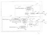
- FIG. 1shows schematically a card of the present invention located in an existing telecommunications box, such as a mutliplexor;
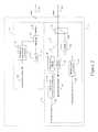
- FIG. 2shows a block diagram of the transceiver of the present invention.
- FIG. 3shows a description of an analog energy level detector of the present invention.
- FIG. 1shows an existing telecommunications box 2 , for example a multiplexor, refitted with a card 1 of the present invention.
- Box 2has an electronic data input 3 and output 4 , which connect to a motherboard 5 of the box 2 .
- Motherboard 5includes a bus 6 for connecting existing amplitude-based cards to the motherboard 5 , and connects the input 3 and output 4 , through for example, data conversion circuitry, to the bus 6 .
- the type of bus 6is dependent upon the box manufacturer, and different types of boxes, motherboards and buses are well known in the art.
- Card 1 of the present inventionincludes electrical connections 8 to fit into bus 6 .
- Card 1also includes a faceplate 9 and a backplane 7 , which preferably is a printed circuit board. Faceplate 9 may be perpendicular to backplane 7 and be flush with a front side of box 2 .
- Faceplate 9may have a fiber connector 109 , such as a duplex SC connector, for connecting to an output fiber 110 and an input fiber 111 .
- a fiber connector 109such as a duplex SC connector
- a single fiber for inputting and outputting signalscould be provided.
- FIG. 2shows the card 1 of the present invention in more detail.
- a transmitter 10transmits signals over optical fiber 110 .
- Transmitter 10includes a single laser 12 , for example a semiconductor laser emitting a narrow band of light at approximately 1550 nm, or at other wavelengths.
- Light emitted from laser 12passes through a modulator 16 , for example an amplitude or phase modulator, directly next to or part of the same package as laser 12 .
- the lightmay be depolarized by a depolarizer 14 .
- An electronic controller 18preferably manufactured directed on the printed circuit board of backplane 7 ( FIG. 1 ), controls modulator 16 and may provide power to laser 12
- Input data 19is fed to the controller 18 , which then controls modulator 16 to modulate the light from laser 12 as a function of the input data 19 .
- the transceiver of the present inventionpreferably operates in a phase-modulated mode, though conventional amplitude-modulated transmitters and receivers, including those using return-to-zero type signals, for example, may also be used.
- the phase-modulated signalshave the advantage that breach detection by the energy level detector work more effectively, since the amplitude of the optical signal is constant and thus a drop in the optical signal level is more easily detected.
- Optical signalsare received at connector 109 from fiber 111 .
- Receiver 11includes two coupler/splitters 31 and 131 , each functioning as a splitter.
- Splitter 131is preferably a wavelength division multiplexed coupler/splitter to allow the OTDR 132 to operate at one optical wavelength, for example 1670 nm, while the transmitted data stream 19 and received data stream 34 are carried on a different wavelength, for example 1550 nm. This functionality allows the OTDR 132 on transceiver card 1 to be commanded to continuously operate without interruption or corruption of the received data stream 34 .
- Splitter 131splits off the wavelength of light applicable to the OTDR into fiber 133 , which has an input to OTDR 132 .
- Splitter 31then splits off a portion of the remaining other light, directing part of the optical energy to an energy level or tap detector 33 and passes the residual light to an optical receiver 32 .
- Optical receiver 32converts the optical signal from optical to electronic form to recover the electronic data stream 34 as appropriate for the optical modulation technique employed.
- OTDR 132has a control circuit 134 and a bus 135 which allows the device to be controlled by a processor.
- the OTDRthus can monitor the fiber 111 and provide information through bus 135 to a processor for determining the location of a breach or tap.
- Detector 33monitors the light energy in the fiber 111 via the light energy coupled to the detector by splitter 31 . If the amplitude drops during monitoring, which may indicate a tap, the detector 33 provides an alert and can, for example, send and electronic signal to the processor via bus 135 to indicate a drop or increase in the optical energy level, sound an alarm or alert network maintenance personnel, for example through an LED 133 or by sending an alarm message using transmitter 10 . Another LED 134 can provide an indication of proper signal reception.
- An energy level detector control circuit 233controls the alarm threshold and energy detection and provides output indications from the energy detection circuit to a processor via bus 135 which may be shared with the OTDR control circuit 134 .
- FIG. 3shows the energy level detector 33 of the present invention in more detail.
- the energy level detector 33 described by FIG. 3represents a preferred analog implementation, with other implementation circuits possible, for bounding the optical energy within an acceptable range with thresholds which may be programmable.
- a photodetector or other optical to electrical conversion device 153measures the optical signal coupled to its input by coupler/splitter 31 .
- the output of photodetector 153is an electrical voltage whose level correlates to the optical power at the input to the photodetector 153 based upon the photodetector 153 transfer optical to electrical conversion transfer function.
- the electrical signalmay be filtered by a low pass filter 154 to provide an average voltage level which represents the average optical power measured by photodetector 153 . After filtering the signal, the electrical signal may be conditioned and scaled by either a logarithmic or linear amplifier 155 .
- Scaling the datamay be necessary to ensure that energy level detection can be made without performance degradation over the span length range required for the circuit.
- the choice of scaling typeis chosen primarily based upon the optical to electrical conversion transfer function of the photodetector and the range of expected optical power levels at the photodetector 153 input based upon span length ranges.
- the transfer function of semiconductor photodetection devicesis exponential with respect to optical to electrical conversion.
- the cascade of an exponential photodetector with a logarithmic amplifieroffers the advantage of providing a net linear transfer function from optical power at the input to the photodetector to voltage at the logarithmic amplifier.
- a digitally programmable detection thresholdcan be developed which offers the same resolution per bit regardless of the span length of the device.
- the electrical signalafter being scaled by the linear or logarithmic amplifier 155 , is compared to reference voltages by one or more comparators. As shown in FIG. 3 , comparator 156 will transition from a low to high output when the voltage output from the logarithmic or linear amplifier 155 exceeds the reference voltage established by the digital to analog (D to A) converter 158 . Conversely, comparator 157 will transition from a low to high output when the voltage output from the logarithmic or linear amplifier 155 falls below the reference voltage established by the digital to analog converter 159 . The output of OR gate 160 will transition from low to high when either the output of comparator 156 or comparator 157 transitions from low to high. For the example of FIG.
- an alarm stateis said to exist when the output of OR gate 160 is high.
- the OR gate outputmay trigger an audible alarm via a siren 162 , a visual alarm via a light or light emitting diode (LED) 161 or may indicate an alarm state to the processor via the energy level detector interface 233 and processor bus 135 .
- the reference voltages established by D to A converters 158 and 159may be programmable through a digital processor or state machine via a digital bus 135 and an energy level detector interface circuit 233 .
- One or more thresholds 163 and 164may be established to provide reference levels for comparison to determine one or more alarm states.
- the circuit of FIG. 3may be configured to monitor in real time the optical power at the receiver 11 for excess light or too little light to indicate a potential optical tap, tamper or other degradation of the optical signal.
- a digital circuit equivalent to FIG. 3may be developed. Analog to digital conversion of the logarithmic or linear amplifier 155 output followed by comparison of the digital result to digital thresholds either via software or digital hardware would indicate optical energy levels within limits or not. Additional filtering via averaging of digital conversions via a moving average or other digital filtering technique could replace or supplement filtering provided by analog filter 154 . A digital implementation also offers information regarding an estimate of the measured optical signal power, both peak and average, by monitoring the analog to digital output via a computer interface.
- OC-3 cardsmay vary in size and certain component types from OC-192 cards.
- the present inventionalso permits for the removal of existing optical transmission cards to be easily replaced by the enhanced security cards.
- the fibersare disconnected, the box 2 is simply opened and the amplitude-modulated-based card is removed.
- the card 1is inserted into the bus 6 and the fibers are connected.
- the card 1 of the present inventionmay thus provide existing boxes with continual breach localization and detection secure transmission mode capability.
- the energy level detectormust be at the receiver side, the OTDR also could be located on the transmitter side.
Landscapes
- Engineering & Computer Science (AREA)
- Physics & Mathematics (AREA)
- Electromagnetism (AREA)
- Computer Networks & Wireless Communication (AREA)
- Signal Processing (AREA)
- Computer Security & Cryptography (AREA)
- Optical Communication System (AREA)
Abstract
Description
Claims (25)
Priority Applications (1)
| Application Number | Priority Date | Filing Date | Title |
|---|---|---|---|
| US13/759,650US8913898B2 (en) | 2001-07-09 | 2013-02-05 | Fiber optic telecommunications card with security detection |
Applications Claiming Priority (4)
| Application Number | Priority Date | Filing Date | Title |
|---|---|---|---|
| US30393201P | 2001-07-09 | 2001-07-09 | |
| US10/188,643US7620327B2 (en) | 2001-07-09 | 2002-07-03 | Fiber optic telecommunications card with energy level monitoring |
| US12/590,185US8374511B2 (en) | 2001-07-09 | 2009-11-04 | Fiber optic telecommunications card with security detection |
| US13/759,650US8913898B2 (en) | 2001-07-09 | 2013-02-05 | Fiber optic telecommunications card with security detection |
Related Parent Applications (1)
| Application Number | Title | Priority Date | Filing Date |
|---|---|---|---|
| US12/590,185ContinuationUS8374511B2 (en) | 2001-07-09 | 2009-11-04 | Fiber optic telecommunications card with security detection |
Publications (2)
| Publication Number | Publication Date |
|---|---|
| US20130148957A1 US20130148957A1 (en) | 2013-06-13 |
| US8913898B2true US8913898B2 (en) | 2014-12-16 |
Family
ID=23174317
Family Applications (10)
| Application Number | Title | Priority Date | Filing Date |
|---|---|---|---|
| US10/188,643Active2026-05-28US7620327B2 (en) | 2001-07-09 | 2002-07-03 | Fiber optic telecommunications card with energy level monitoring |
| US12/590,185Expired - Fee RelatedUS8374511B2 (en) | 2001-07-09 | 2009-11-04 | Fiber optic telecommunications card with security detection |
| US13/759,650Expired - Fee RelatedUS8913898B2 (en) | 2001-07-09 | 2013-02-05 | Fiber optic telecommunications card with security detection |
| US13/762,717Expired - Fee RelatedUS9363012B2 (en) | 2001-07-09 | 2013-02-08 | Fiber optic telecommunications card with energy level monitoring |
| US15/159,282Expired - Fee RelatedUS9749040B2 (en) | 2001-07-09 | 2016-05-19 | Fiber optic telecommunications card with energy level monitoring |
| US15/680,915Expired - Fee RelatedUS10205516B2 (en) | 2001-07-09 | 2017-08-18 | Fiber optic telecommunications card with energy level monitoring |
| US15/933,052Expired - Fee RelatedUS10205517B2 (en) | 2001-07-09 | 2018-03-22 | Optical line card for wavelength division multiplexed signals |
| US16/273,899Expired - Fee RelatedUS10554297B2 (en) | 2001-07-09 | 2019-02-12 | Fiber optic telecommunications card with security detection |
| US16/274,120Expired - Fee RelatedUS10560185B2 (en) | 2001-07-09 | 2019-02-12 | Optical line card with optical signal power monitor |
| US16/788,048Expired - Fee RelatedUS10833761B2 (en) | 2001-07-09 | 2020-02-11 | Optical transceiver |
Family Applications Before (2)
| Application Number | Title | Priority Date | Filing Date |
|---|---|---|---|
| US10/188,643Active2026-05-28US7620327B2 (en) | 2001-07-09 | 2002-07-03 | Fiber optic telecommunications card with energy level monitoring |
| US12/590,185Expired - Fee RelatedUS8374511B2 (en) | 2001-07-09 | 2009-11-04 | Fiber optic telecommunications card with security detection |
Family Applications After (7)
| Application Number | Title | Priority Date | Filing Date |
|---|---|---|---|
| US13/762,717Expired - Fee RelatedUS9363012B2 (en) | 2001-07-09 | 2013-02-08 | Fiber optic telecommunications card with energy level monitoring |
| US15/159,282Expired - Fee RelatedUS9749040B2 (en) | 2001-07-09 | 2016-05-19 | Fiber optic telecommunications card with energy level monitoring |
| US15/680,915Expired - Fee RelatedUS10205516B2 (en) | 2001-07-09 | 2017-08-18 | Fiber optic telecommunications card with energy level monitoring |
| US15/933,052Expired - Fee RelatedUS10205517B2 (en) | 2001-07-09 | 2018-03-22 | Optical line card for wavelength division multiplexed signals |
| US16/273,899Expired - Fee RelatedUS10554297B2 (en) | 2001-07-09 | 2019-02-12 | Fiber optic telecommunications card with security detection |
| US16/274,120Expired - Fee RelatedUS10560185B2 (en) | 2001-07-09 | 2019-02-12 | Optical line card with optical signal power monitor |
| US16/788,048Expired - Fee RelatedUS10833761B2 (en) | 2001-07-09 | 2020-02-11 | Optical transceiver |
Country Status (4)
| Country | Link |
|---|---|
| US (10) | US7620327B2 (en) |
| EP (1) | EP1405444B1 (en) |
| AU (1) | AU2002318180A1 (en) |
| WO (1) | WO2003007024A2 (en) |
Families Citing this family (40)
| Publication number | Priority date | Publication date | Assignee | Title |
|---|---|---|---|---|
| AU2002318180A1 (en)* | 2001-07-09 | 2003-01-29 | Oyster Optics, Inc. | Fiber optic telecommunications card with security detection |
| US9312953B2 (en) | 2003-03-03 | 2016-04-12 | Alexander Ivan Soto | System and method for performing in-service optical network certification |
| US8655166B2 (en)* | 2003-03-03 | 2014-02-18 | Alexander I Soto | System and method for performing in-service optical fiber network certification |
| WO2004079404A2 (en)* | 2003-03-03 | 2004-09-16 | UBI SYSTEMS, INC. (A Delaware Corporation) | System and method for performing in-service fiber optic network certification |
| US20090016714A1 (en)* | 2003-03-03 | 2009-01-15 | Alexander Soto | System and method for performing in-service fiber optic network certification |
| US10608736B2 (en)* | 2003-03-03 | 2020-03-31 | Alexander Soto | System and method for performing in-service optical network certification |
| DE102005002195A1 (en)* | 2005-01-17 | 2006-07-27 | Siemens Ag | Optical data signal regenerating method for transmission system, involves measuring received output of optical data signal and adjusting sampling threshold as function of received output corresponding to preset logarithmic function |
| ES2298967T3 (en)* | 2005-09-12 | 2008-05-16 | Alcatel Lucent | OPTICAL TRANSMITTER-RECEIVER MODULE TO MONITOR AN OPTICAL FIBER AND METHOD TO MAKE AVAILABLE MEASUREMENT DATA FROM THE MONITORING OF AN OPTICAL FIBER. |
| DE102005063102A1 (en)* | 2005-12-30 | 2007-07-12 | Adva Ag Optical Networking | Method and device for monitoring an optical transmission path, in particular an optical transmission path to an end user of a transmission network |
| US8180216B2 (en)* | 2007-12-20 | 2012-05-15 | Verizon Patent And Licensing Inc. | Latency measurement in optical networks |
| US8521019B2 (en)* | 2008-07-14 | 2013-08-27 | Nanotech Semiconductor Ltd. | Method and system for closed loop control of an optical link |
| US8971704B2 (en)* | 2009-12-03 | 2015-03-03 | Telefonaktiebolaget L M Ericsson (Publ) | Optical networks |
| US9215006B2 (en)* | 2010-12-28 | 2015-12-15 | Verizon Patent And Licensing Inc. | Apparatus and method for efficient optical loss measurement |
| WO2012093431A1 (en)* | 2011-01-07 | 2012-07-12 | パナソニック株式会社 | Optical transmission system |
| EP3823345B1 (en)* | 2012-03-21 | 2022-07-13 | Samsung Electronics Co., Ltd. | Granular network access control and methods thereof |
| KR20130126834A (en)* | 2012-05-02 | 2013-11-21 | 한국전자통신연구원 | Optical layer monitoring apparatus and method thereof |
| US9577748B2 (en)* | 2012-05-07 | 2017-02-21 | Telefonaktiebolaget L M Ericsson | Monitoring of a passive optical network (PON) |
| US9140624B2 (en)* | 2012-07-03 | 2015-09-22 | Ciena Corporation | Systems and methods reducing coherence effect in narrow line-width light sources |
| US9219543B2 (en)* | 2012-07-11 | 2015-12-22 | Commscope Technologies Llc | Monitoring optical decay in fiber connectivity systems |
| WO2015055230A1 (en) | 2013-10-15 | 2015-04-23 | Telefonaktiebolaget L M Ericsson (Publ) | Transmitting communications traffic across an optical communication network |
| US9537979B2 (en)* | 2014-12-12 | 2017-01-03 | Intel Corporation | Network adapter optical alert system |
| US10284288B2 (en) | 2016-02-18 | 2019-05-07 | Apriori Network Systems, Llc | Secured fiber link system |
| US10763962B2 (en) | 2016-02-18 | 2020-09-01 | Apriori Network Systems, Llc. | Secured fiber link system |
| US10784969B2 (en)* | 2016-02-18 | 2020-09-22 | Apriori Network Systems, Llc. | Secured fiber link system |
| US9847831B2 (en) | 2016-04-08 | 2017-12-19 | Ciena Corporation | Dual wavelenth optical time domain reflectometer systems and methods embedded in a WDM system |
| US10161798B2 (en)* | 2016-06-09 | 2018-12-25 | Ciena Corporation | Integrated polarimeter in an optical line system |
| CN106953687B (en)* | 2017-01-19 | 2023-09-05 | 中铁第四勘察设计院集团有限公司 | POTDR system based on Simplex coding and signal determination method thereof |
| US11249130B2 (en)* | 2017-12-29 | 2022-02-15 | Texas Instruments Incorporated | Direct current measurement of 1/f transistor noise |
| JPWO2020044661A1 (en)* | 2018-08-30 | 2021-08-26 | 日本電気株式会社 | Optical pulse tester, optical transmission line test method and optical transmission line test system |
| CN109412686A (en)* | 2018-10-30 | 2019-03-01 | 郑州云海信息技术有限公司 | A kind of optical power detection system and method |
| CN111435854A (en)* | 2019-01-14 | 2020-07-21 | 中国移动通信有限公司研究院 | Method, apparatus, system and computer readable storage medium for detecting optical fiber failure |
| US10700700B1 (en)* | 2019-03-20 | 2020-06-30 | Raytheon Company | Distributive photonic monobit analog-to-digital converter |
| US11216251B2 (en) | 2019-03-20 | 2022-01-04 | Raytheon Company | Wideband photonic radio frequency (RF) noise generator |
| US10833768B2 (en) | 2019-03-20 | 2020-11-10 | Raytheon Company | Photonic monobit analog-to-digital converter using coherent detection |
| US10727862B1 (en)* | 2019-03-20 | 2020-07-28 | Raytheon Company | Photonic monobit differential analog-to-digital converter |
| CN112583476B (en)* | 2019-09-27 | 2022-05-17 | 华为技术有限公司 | Optical network terminal and optical fiber test method |
| CN111211837A (en)* | 2020-01-16 | 2020-05-29 | 新疆大学 | Visible light communication system based on optical fiber energy supply |
| EP3917034A1 (en)* | 2020-05-27 | 2021-12-01 | Telia Company AB | Monitor of optical fiber |
| CN116349163A (en)* | 2020-11-12 | 2023-06-27 | 阿里巴巴集团控股有限公司 | System and method for real-time monitoring of fiber performance |
| CN113175988B (en)* | 2021-04-13 | 2022-04-19 | 太原理工大学 | A Distributed Optical Fiber Sound Sensing Device with Anti-noise and Breakpoint Self-diagnosis |
Citations (7)
| Publication number | Priority date | Publication date | Assignee | Title |
|---|---|---|---|---|
| US5062704A (en)* | 1990-04-25 | 1991-11-05 | Tektronix, Inc. | Optical time domain reflectometer having pre and post front panel connector testing capabilities |
| US5202782A (en)* | 1990-01-19 | 1993-04-13 | Canon Kabushiki Kaisha | Optical communication method and optical communication system |
| US5539560A (en)* | 1994-12-05 | 1996-07-23 | Photon Kinetics, Inc. | Optical router with optical control |
| US5561727A (en)* | 1994-02-15 | 1996-10-01 | Sumitomo Electric Industries, Ltd. | Card-shaped optical data link device |
| US5680234A (en)* | 1994-10-20 | 1997-10-21 | Lucent Technologies Inc. | Passive optical network with bi-directional optical spectral slicing and loop-back |
| US6515777B1 (en)* | 1999-03-12 | 2003-02-04 | Marconi Communications Limited | Ring gain control in WDM optical signal transmission system |
| US20110013911A1 (en)* | 1995-05-11 | 2011-01-20 | Alexander Stephen B | High-speed optical transponder systems |
Family Cites Families (86)
| Publication number | Priority date | Publication date | Assignee | Title |
|---|---|---|---|---|
| US36430A (en)* | 1862-09-09 | Improvement in harvesters | ||
| FR2511566A1 (en)* | 1981-08-12 | 1983-02-18 | Thomson Csf | THRESHOLD OPTICAL RECEIVER FOR DIGITAL RATE DIGITAL TRANSMISSION SYSTEM |
| US5223967A (en)* | 1986-06-11 | 1993-06-29 | Mcdonnell Douglas Corporation | Secure communications system |
| US4754452A (en)* | 1986-09-11 | 1988-06-28 | American Telephone And Telegraph Company, At&T Bell Laboratories | Optical local area network using a common optical carrier with separate user angle modulation |
| US4709415A (en)* | 1986-11-14 | 1987-11-24 | Warner Cable Communications, Inc. | T-carrier fiber optic modem |
| GB8709900D0 (en)* | 1987-04-27 | 1987-08-05 | British Telecomm | Surveillance system |
| US4933929A (en)* | 1987-06-29 | 1990-06-12 | Nec Corporation | Wavelength multiplexed optical transmitter for generating constant-amplitude angle-modulated beams to eliminate phase noise in adjacent transmission channels |
| US4824201A (en)* | 1987-07-13 | 1989-04-25 | Bell Communications Research, Inc. | Simultaneous transmission of LED and laser signals over single mode fiber |
| FR2637432B1 (en)* | 1988-10-03 | 1990-11-30 | Telecommunications Sa | FIBER OPTIC LINK MONITORING SYSTEM |
| US4998295A (en)* | 1988-12-30 | 1991-03-05 | General Electric Company | Receiver having an interferometer |
| US5455698A (en)* | 1989-12-27 | 1995-10-03 | Mcdonnell Douglas Corporation | Secure communication alarm system |
| FR2660131B1 (en)* | 1990-03-23 | 1992-06-19 | France Etat | DEVICE FOR TRANSMITTING DIGITAL DATA WITH AT LEAST TWO LEVELS OF PROTECTION, AND CORRESPONDING RECEPTION DEVICE. |
| JPH0410722A (en)* | 1990-04-27 | 1992-01-14 | Hitachi Ltd | Coherent communication methods, cross-connect devices and switching devices |
| US5214728A (en)* | 1990-06-19 | 1993-05-25 | Sumitomo Electric Industries, Ltd. | Light communication system |
| US5285548A (en)* | 1990-06-21 | 1994-02-15 | Moll Christopher A | Brushing apparatus for cleaning and polishing pumpkins and the like |
| EP0772314A3 (en)* | 1990-09-14 | 1997-09-03 | Fujitsu Ltd | Optical communication system with sub-carrier multiplexing |
| US5146079A (en)* | 1990-11-01 | 1992-09-08 | At&T Bell Laboratories | Broadband optical receiver with active bias feedback circuit |
| CA2139516C (en)* | 1990-12-24 | 2000-02-08 | Kazimierz Siwiak | Dual mode receiver having battery saving capability |
| DE69232943T2 (en)* | 1991-05-13 | 2003-08-28 | Xircom Wireless, Inc. | TRANSMITTER / RECEIVER WITH TWO OPERATING MODES |
| JP2776094B2 (en)* | 1991-10-31 | 1998-07-16 | 日本電気株式会社 | Variable modulation communication method |
| US5319438A (en)* | 1992-01-24 | 1994-06-07 | Board Of Regents, The University Of Texas System | Interferometric, self-homodyne optical receiver and method and optical transmission system incorporating same |
| JPH0653904A (en) | 1992-07-31 | 1994-02-25 | Toshiba Corp | Optical transmitter |
| US5452086A (en)* | 1993-03-22 | 1995-09-19 | Litton Systems, Inc. | Interferometer amplitude modulation reduction circuit |
| AU678049B2 (en)* | 1993-09-09 | 1997-05-15 | British Telecommunications Public Limited Company | System and method for quantum cryptography |
| JP3028906B2 (en)* | 1994-01-27 | 2000-04-04 | ケイディディ株式会社 | Soliton optical communication system and optical transmitting device and optical receiving device thereof |
| US5487120A (en)* | 1994-02-09 | 1996-01-23 | International Business Machines Corporation | Optical wavelength division multiplexer for high speed, protocol-independent serial data sources |
| US5459600A (en)* | 1994-03-08 | 1995-10-17 | Optimux Systems Corporation | Optical telecommunications system employing multiple phase-compensated optical signals |
| US5572350A (en)* | 1994-03-31 | 1996-11-05 | Lucent Technologies Inc. | Method and apparatus to compensate for differential attenuation in an optical time slot interchanger |
| US5479539A (en)* | 1994-06-15 | 1995-12-26 | Texas Instruments Incorporated | Integrated optical transmitter and receiver |
| US5543952A (en)* | 1994-09-12 | 1996-08-06 | Nippon Telegraph And Telephone Corporation | Optical transmission system |
| EP0783717A1 (en)* | 1994-09-30 | 1997-07-16 | Siemens Aktiengesellschaft | Device for interconnecting electronic apparatuses and allowing them to communicate with each other |
| JP2950739B2 (en)* | 1994-11-11 | 1999-09-20 | 沖電気工業株式会社 | Dual mode transmitter |
| US5907417A (en)* | 1994-12-30 | 1999-05-25 | Lucent Technologies Inc. | Passive optical network with diagnostic loop-back |
| JPH08204636A (en)* | 1995-01-25 | 1996-08-09 | Kokusai Denshin Denwa Co Ltd <Kdd> | Optical communication system |
| US5726784A (en)* | 1995-05-11 | 1998-03-10 | Ciena Corp. | WDM optical communication system with remodulators and diverse optical transmitters |
| US5953421A (en)* | 1995-08-16 | 1999-09-14 | British Telecommunications Public Limited Company | Quantum cryptography |
| SE515536C2 (en)* | 1995-08-16 | 2001-08-27 | Ericsson Telefon Ab L M | Dispensing compensation |
| US5940452A (en)* | 1995-11-29 | 1999-08-17 | Motorola, Inc. | Dual mode radio subscriber unit having a diversity receiver apparatus and method therefor |
| JP3299101B2 (en)* | 1995-12-15 | 2002-07-08 | 日本電気株式会社 | WDM optical communication equipment |
| US6005694A (en)* | 1995-12-28 | 1999-12-21 | Mci Worldcom, Inc. | Method and system for detecting optical faults within the optical domain of a fiber communication network |
| JP3411436B2 (en)* | 1996-01-12 | 2003-06-03 | Kddi株式会社 | Monitoring method of optical communication line |
| US20010044588A1 (en)* | 1996-02-22 | 2001-11-22 | Mault James R. | Monitoring system |
| FR2745451B1 (en)* | 1996-02-23 | 1998-04-17 | Cit Alcatel | METHOD FOR OPTICAL TRANSMISSION OF DIGITAL DATA |
| US5953139A (en)* | 1996-03-06 | 1999-09-14 | Cfx Communications Systems, Llc | Wavelength division multiplexing system |
| US6087947A (en)* | 1996-07-11 | 2000-07-11 | Robert N. Hamburger | Allergen detector system and method |
| JP3027944B2 (en)* | 1996-08-16 | 2000-04-04 | 日本電気株式会社 | Optical duobinary signal light generation method and optical transmitter |
| US5946119A (en)* | 1997-02-12 | 1999-08-31 | Tyco Submarine Systems Ltd. | Wavelength division multiplexed system employing optimal channel modulation |
| DE19722370A1 (en)* | 1997-05-28 | 1998-12-03 | Alsthom Cge Alcatel | Receiver for an optical communication system and method for its operation |
| US6072615A (en)* | 1997-06-13 | 2000-06-06 | Lucent Technologies Inc. | Phase modulator-based generation of high-quality high bit rate return-to-zero optical data streams |
| CA2301155A1 (en)* | 1997-08-18 | 1999-02-25 | Sergio Bosso | Narrow-band optical modulator with reduced power requirement |
| JP4184474B2 (en)* | 1997-08-22 | 2008-11-19 | 松下電器産業株式会社 | OPTICAL TRANSMISSION SYSTEM AND OPTICAL TRANSMITTING DEVICE AND OPTICAL RECEIVING DEVICE USED FOR THE SAME |
| DE19737482A1 (en)* | 1997-08-28 | 1999-03-04 | Alsthom Cge Alcatel | Process for optical transmission over an optical fiber network, and optical transmission network |
| US6124960A (en)* | 1997-09-08 | 2000-09-26 | Northern Telecom Limited | Transmission system with cross-phase modulation compensation |
| US6307659B1 (en)* | 1997-09-24 | 2001-10-23 | Stratos Lightwave, Inc. | Optoelectronic transceiver having an adaptable logic level signal detect output |
| US6008900A (en)* | 1998-02-10 | 1999-12-28 | Litton Systems, Inc. | Method and apparatus for calibration of a multi-channel fiber optic interferometric sensor system in a signal processing system |
| US6215565B1 (en)* | 1998-07-27 | 2001-04-10 | Mci Communications Corporation | Method of and system for diagnosing optical system failures |
| US6559996B1 (en) | 1998-07-29 | 2003-05-06 | Nippon Telegraph And Telephone Corporation | Optical transmission system |
| US6271950B1 (en)* | 1998-08-18 | 2001-08-07 | Lucent Technologies Inc. | Optical differential phase shift keying transmission system having multiplexing, routing and add/replace capabilities |
| US6157443A (en)* | 1998-08-19 | 2000-12-05 | Lucent Technologies Inc. | Method and system for transporting data for monitoring optical fibers |
| JP2000150997A (en)* | 1998-11-13 | 2000-05-30 | Nec Corp | Optical amplifier, optical transmission device equipped therewith and with fracture point detecting function and bidirectional optical transmission device |
| US6362908B1 (en)* | 1998-12-02 | 2002-03-26 | Marconi Communications, Inc. | Multi-service adaptable optical network unit |
| US6396605B1 (en)* | 1999-01-26 | 2002-05-28 | Trw Inc. | Apparatus and method for tuning an optical interferometer |
| US6690890B1 (en)* | 1999-03-10 | 2004-02-10 | Eric Udd | Single fiber Sagnac interferometer based secure communication system |
| US6201632B1 (en)* | 1999-05-28 | 2001-03-13 | Trw Inc. | Feed forward optical frequency/phase demodulator |
| NO322073B1 (en)* | 1999-06-23 | 2006-08-07 | Optoplan As | Polarization Control Procedure |
| US6549311B1 (en)* | 1999-07-14 | 2003-04-15 | Lucent Technologies Inc. | Wave division multiplexing channel telemetry by phase modulation |
| DE19949401A1 (en)* | 1999-10-13 | 2001-04-19 | Siemens Ag | Method and device for the continuous monitoring of an optical transmission link |
| US6819879B1 (en)* | 1999-12-29 | 2004-11-16 | Nortel Networks Limited | Method and apparatus for encoding optical power and non-payload data in an optical signal |
| US6826371B1 (en) | 2000-06-15 | 2004-11-30 | Northrop Grumman Corporation | Variable rate DPSK system architecture |
| US6285548B1 (en) | 2000-08-18 | 2001-09-04 | Quantum Bridge Communications, Inc. | Face plate for a chassis for high frequency components |
| US6826372B1 (en)* | 2000-08-30 | 2004-11-30 | Sycamore Networks, Inc. | Methods and apparatus for dynamic threshold setting for an optically amplified receiver |
| US6574268B1 (en)* | 2000-11-21 | 2003-06-03 | Bbnt Solutions Llc | Asymmetric orthogonal codes for optical communications |
| US6528777B2 (en)* | 2001-01-16 | 2003-03-04 | International Business Machines Corporation | Optical power meter derived from common-mode voltage of optical transimpedance amplifier |
| US6469816B1 (en)* | 2001-05-24 | 2002-10-22 | Oyster Optics, Inc. | Phase-modulated fiber optic telecommunications system |
| US6594055B2 (en)* | 2001-01-17 | 2003-07-15 | Oyster Optics, Inc. | Secure fiber optic telecommunications system and method |
| US6476952B1 (en)* | 2001-01-17 | 2002-11-05 | Oyster Optics, Inc. | Phase-modulated fiber optic telecommunications system |
| US6665500B2 (en)* | 2001-01-29 | 2003-12-16 | Oyster Optics, Inc. | Dual-mode fiber optic telecommunications system and method |
| US7099592B2 (en)* | 2001-02-02 | 2006-08-29 | Oyster Optics, Inc. | Telecommunications card for secure optical data transmission and installation method |
| US6529316B1 (en)* | 2001-05-03 | 2003-03-04 | Onetta, Inc. | Optical network equipment with optical channel monitor and dynamic spectral filter alarms |
| US7035543B1 (en)* | 2001-05-10 | 2006-04-25 | Fujitsu Limited | Method and system for demultiplexing non-intensity modulated wavelength division multiplexed (WDM) signals |
| US7200344B1 (en)* | 2001-05-10 | 2007-04-03 | Fujitsu Limited | Receiver and method for a multichannel optical communication system |
| US6915076B1 (en)* | 2001-05-14 | 2005-07-05 | Ciena Corporation | System and method for adaptively selecting a signal threshold of an optical link |
| US20020196501A1 (en)* | 2001-06-26 | 2002-12-26 | Robert Buss | Tandem optoelectronic transciver package and method of operating an optical fiber communication network employing the same |
| AU2002318180A1 (en)* | 2001-07-09 | 2003-01-29 | Oyster Optics, Inc. | Fiber optic telecommunications card with security detection |
| US6643046B2 (en)* | 2001-09-26 | 2003-11-04 | Kabushiki Kaisha Toshiba | Apparatus and method for optical modulation |
| US6990296B2 (en)* | 2001-12-21 | 2006-01-24 | Fujitsu Limited | Optical phase modulation |
- 2002
- 2002-07-03AUAU2002318180Apatent/AU2002318180A1/ennot_activeAbandoned
- 2002-07-03WOPCT/US2002/021047patent/WO2003007024A2/ennot_activeApplication Discontinuation
- 2002-07-03EPEP02748055Apatent/EP1405444B1/ennot_activeExpired - Lifetime
- 2002-07-03USUS10/188,643patent/US7620327B2/enactiveActive
- 2009
- 2009-11-04USUS12/590,185patent/US8374511B2/ennot_activeExpired - Fee Related
- 2013
- 2013-02-05USUS13/759,650patent/US8913898B2/ennot_activeExpired - Fee Related
- 2013-02-08USUS13/762,717patent/US9363012B2/ennot_activeExpired - Fee Related
- 2016
- 2016-05-19USUS15/159,282patent/US9749040B2/ennot_activeExpired - Fee Related
- 2017
- 2017-08-18USUS15/680,915patent/US10205516B2/ennot_activeExpired - Fee Related
- 2018
- 2018-03-22USUS15/933,052patent/US10205517B2/ennot_activeExpired - Fee Related
- 2019
- 2019-02-12USUS16/273,899patent/US10554297B2/ennot_activeExpired - Fee Related
- 2019-02-12USUS16/274,120patent/US10560185B2/ennot_activeExpired - Fee Related
- 2020
- 2020-02-11USUS16/788,048patent/US10833761B2/ennot_activeExpired - Fee Related
Patent Citations (7)
| Publication number | Priority date | Publication date | Assignee | Title |
|---|---|---|---|---|
| US5202782A (en)* | 1990-01-19 | 1993-04-13 | Canon Kabushiki Kaisha | Optical communication method and optical communication system |
| US5062704A (en)* | 1990-04-25 | 1991-11-05 | Tektronix, Inc. | Optical time domain reflectometer having pre and post front panel connector testing capabilities |
| US5561727A (en)* | 1994-02-15 | 1996-10-01 | Sumitomo Electric Industries, Ltd. | Card-shaped optical data link device |
| US5680234A (en)* | 1994-10-20 | 1997-10-21 | Lucent Technologies Inc. | Passive optical network with bi-directional optical spectral slicing and loop-back |
| US5539560A (en)* | 1994-12-05 | 1996-07-23 | Photon Kinetics, Inc. | Optical router with optical control |
| US20110013911A1 (en)* | 1995-05-11 | 2011-01-20 | Alexander Stephen B | High-speed optical transponder systems |
| US6515777B1 (en)* | 1999-03-12 | 2003-02-04 | Marconi Communications Limited | Ring gain control in WDM optical signal transmission system |
Also Published As
| Publication number | Publication date |
|---|---|
| US20190190596A1 (en) | 2019-06-20 |
| AU2002318180A1 (en) | 2003-01-29 |
| US20130148957A1 (en) | 2013-06-13 |
| US20030007215A1 (en) | 2003-01-09 |
| WO2003007024A3 (en) | 2003-06-05 |
| US20130148959A1 (en) | 2013-06-13 |
| US20190181948A1 (en) | 2019-06-13 |
| US8374511B2 (en) | 2013-02-12 |
| US20180212677A1 (en) | 2018-07-26 |
| US10554297B2 (en) | 2020-02-04 |
| US20170373747A1 (en) | 2017-12-28 |
| US10833761B2 (en) | 2020-11-10 |
| US20160269107A1 (en) | 2016-09-15 |
| US9363012B2 (en) | 2016-06-07 |
| US10560185B2 (en) | 2020-02-11 |
| US20100119225A1 (en) | 2010-05-13 |
| US10205517B2 (en) | 2019-02-12 |
| EP1405444A4 (en) | 2006-10-04 |
| US7620327B2 (en) | 2009-11-17 |
| EP1405444B1 (en) | 2013-01-23 |
| US9749040B2 (en) | 2017-08-29 |
| EP1405444A2 (en) | 2004-04-07 |
| US10205516B2 (en) | 2019-02-12 |
| US20200177273A1 (en) | 2020-06-04 |
| WO2003007024A2 (en) | 2003-01-23 |
Similar Documents
| Publication | Publication Date | Title |
|---|---|---|
| US10833761B2 (en) | Optical transceiver | |
| US7920787B2 (en) | Method for detecting a check-back signal in an optical transmission system | |
| KR100663462B1 (en) | Passive Optical Subscriber Network | |
| US7389045B2 (en) | Apparatus and method for monitoring and compensating an optical signal | |
| EP0850514B1 (en) | System, method and device for monitoring a fiber optic cable | |
| US6124957A (en) | Optical signal translator unit | |
| US7099592B2 (en) | Telecommunications card for secure optical data transmission and installation method | |
| RU2152689C1 (en) | Device, method and instrument for checking fiber-optical cable | |
| KR200309696Y1 (en) | Apparatus of Transmitting Optical Signal having Optical Power Meter | |
| JPH0650845B2 (en) | Optical signal transmission system | |
| JP2550878B2 (en) | Optical transceiver circuit | |
| JPH09130332A (en) | Optical signal alarming circuit | |
| US20060110160A1 (en) | Method and device for the transmission of information by means of an optical data transmission system | |
| JPH05327622A (en) | Optical transmitter | |
| JPH0783796A (en) | Light emitting element normal / abnormal check method |
Legal Events
| Date | Code | Title | Description |
|---|---|---|---|
| AS | Assignment | Owner name:OYSTER OPTICS, INC., FLORIDA Free format text:ASSIGNMENT OF ASSIGNORS INTEREST;ASSIGNOR:SNAWERDT, PETER;REEL/FRAME:030334/0372 Effective date:20091005 | |
| AS | Assignment | Owner name:TQ GAMMA, LLC, TEXAS Free format text:ASSIGNMENT OF ASSIGNORS INTEREST;ASSIGNOR:OYSTER OPTICS, INC.;REEL/FRAME:030347/0536 Effective date:20111115 | |
| STCF | Information on status: patent grant | Free format text:PATENTED CASE | |
| CC | Certificate of correction | ||
| AS | Assignment | Owner name:OYSTER OPTICS, LLC, SOUTH CAROLINA Free format text:ASSIGNMENT OF ASSIGNORS INTEREST;ASSIGNOR:TQ GAMMA, LLC;REEL/FRAME:039415/0120 Effective date:20160715 | |
| CC | Certificate of correction | ||
| IPR | Aia trial proceeding filed before the patent and appeal board: inter partes review | Free format text:TRIAL NO: IPR2017-01881 Opponent name:CISCO SYSTEMS, INC. AND OCLARO, INC. Effective date:20170727 | |
| IPR | Aia trial proceeding filed before the patent and appeal board: inter partes review | Free format text:TRIAL NO: IPR2017-01870 Opponent name:CISCO SYSTEMS, INC. AND OCLARO, INC. Effective date:20170727 | |
| IPR | Aia trial proceeding filed before the patent and appeal board: inter partes review | Free format text:TRIAL NO: IPR2018-00070 Opponent name:INFINERA CORPORATION,ALCATEL-LUCENT USA INC.,ALCAT Effective date:20171023 | |
| FEPP | Fee payment procedure | Free format text:ENTITY STATUS SET TO SMALL (ORIGINAL EVENT CODE: SMAL) | |
| MAFP | Maintenance fee payment | Free format text:PAYMENT OF MAINTENANCE FEE, 4TH YR, SMALL ENTITY (ORIGINAL EVENT CODE: M2551) Year of fee payment:4 | |
| IPR | Aia trial proceeding filed before the patent and appeal board: inter partes review | Free format text:TRIAL NO: IPR2018-00257 Opponent name:ALCATEL-LUCENT USA INC., ALCATEL-LUCENT SA, CIENA Effective date:20171201 | |
| STCV | Information on status: appeal procedure | Free format text:APPLICATION INVOLVED IN COURT PROCEEDINGS | |
| STCV | Information on status: appeal procedure | Free format text:APPLICATION INVOLVED IN COURT PROCEEDINGS | |
| IPRC | Trial and appeal board: inter partes review certificate | Kind code of ref document:K1 Free format text:INTER PARTES REVIEW CERTIFICATE; TRIAL NO. IPR2017-01881, JUL. 27, 2017; TRIAL NO. IPR2018-00070, OCT. 23, 2017 INTER PARTES REVIEW CERTIFICATE FOR PATENT 8,913,898, ISSUED DEC. 16, 2014, APPL. NO. 13/759,650, FEB. 5, 2013 INTER PARTES REVIEW CERTIFICATE ISSUED APR. 26, 2021 Effective date:20210426 | |
| FEPP | Fee payment procedure | Free format text:MAINTENANCE FEE REMINDER MAILED (ORIGINAL EVENT CODE: REM.); ENTITY STATUS OF PATENT OWNER: SMALL ENTITY | |
| LAPS | Lapse for failure to pay maintenance fees | Free format text:PATENT EXPIRED FOR FAILURE TO PAY MAINTENANCE FEES (ORIGINAL EVENT CODE: EXP.); ENTITY STATUS OF PATENT OWNER: SMALL ENTITY | |
| STCH | Information on status: patent discontinuation | Free format text:PATENT EXPIRED DUE TO NONPAYMENT OF MAINTENANCE FEES UNDER 37 CFR 1.362 | |
| FP | Lapsed due to failure to pay maintenance fee | Effective date:20221216 |